JP7422598B2 - Control device and control method - Google Patents
Control device and control method Download PDFInfo
- Publication number
- JP7422598B2 JP7422598B2 JP2020070986A JP2020070986A JP7422598B2 JP 7422598 B2 JP7422598 B2 JP 7422598B2 JP 2020070986 A JP2020070986 A JP 2020070986A JP 2020070986 A JP2020070986 A JP 2020070986A JP 7422598 B2 JP7422598 B2 JP 7422598B2
- Authority
- JP
- Japan
- Prior art keywords
- unit
- allocation result
- information
- allocation
- control unit
- Prior art date
- Legal status (The legal status is an assumption and is not a legal conclusion. Google has not performed a legal analysis and makes no representation as to the accuracy of the status listed.)
- Active
Links
Images








Classifications
-
- H—ELECTRICITY
- H04—ELECTRIC COMMUNICATION TECHNIQUE
- H04W—WIRELESS COMMUNICATION NETWORKS
- H04W72/00—Local resource management
- H04W72/20—Control channels or signalling for resource management
- H04W72/21—Control channels or signalling for resource management in the uplink direction of a wireless link, i.e. towards the network
-
- H—ELECTRICITY
- H04—ELECTRIC COMMUNICATION TECHNIQUE
- H04W—WIRELESS COMMUNICATION NETWORKS
- H04W88/00—Devices specially adapted for wireless communication networks, e.g. terminals, base stations or access point devices
- H04W88/08—Access point devices
- H04W88/085—Access point devices with remote components
-
- H—ELECTRICITY
- H04—ELECTRIC COMMUNICATION TECHNIQUE
- H04W—WIRELESS COMMUNICATION NETWORKS
- H04W72/00—Local resource management
- H04W72/04—Wireless resource allocation
- H04W72/044—Wireless resource allocation based on the type of the allocated resource
- H04W72/0446—Resources in time domain, e.g. slots or frames
-
- H—ELECTRICITY
- H04—ELECTRIC COMMUNICATION TECHNIQUE
- H04W—WIRELESS COMMUNICATION NETWORKS
- H04W72/00—Local resource management
- H04W72/04—Wireless resource allocation
- H04W72/044—Wireless resource allocation based on the type of the allocated resource
- H04W72/0453—Resources in frequency domain, e.g. a carrier in FDMA
-
- H—ELECTRICITY
- H04—ELECTRIC COMMUNICATION TECHNIQUE
- H04W—WIRELESS COMMUNICATION NETWORKS
- H04W72/00—Local resource management
- H04W72/50—Allocation or scheduling criteria for wireless resources
- H04W72/53—Allocation or scheduling criteria for wireless resources based on regulatory allocation policies
Landscapes
- Engineering & Computer Science (AREA)
- Computer Networks & Wireless Communication (AREA)
- Signal Processing (AREA)
- Mobile Radio Communication Systems (AREA)
Description
本開示は、制御装置及び制御方法に関する。 The present disclosure relates to a control device and a control method.
無線システムには、Centralized - Radio Access Network(C―RAN)と称されるアーキテクチャが検討されている。C-RANでは、基地局機能が、中央局(Central Unit(CU))と、分散局(Distributed Unit(DU))とに分割して配置される。例えば、国際標準化団体である3rd Generation Partnership Project(3GPP)では、第5世代移動通信システム(5th Generation mobile communication systems(5G))における低遅延及び高スループットといった多様なサービス要求に応えるため、CUとDUとの間の機能配置に関して検討される。 For wireless systems, an architecture called Centralized-Radio Access Network (C-RAN) is being considered. In C-RAN, base station functions are divided into a central unit (CU) and a distributed unit (DU). For example, the 3rd Generation Partnership Project (3GPP), an international standards organization, has developed a system for CU and DU to meet the various service requirements such as low latency and high throughput in 5th Generation mobile communication systems (5G). The functional arrangement between the two will be considered.
また、Open - Radio Access Network(O-RAN)では、CUとDUに加えて、無線局(Radio Unit(RU))が規定され、DUとRUとの間をフロントホールと呼ばれる通信インターフェイスで接続する構成について仕様の標準化が進められる。 Additionally, in Open-Radio Access Network (O-RAN), in addition to CU and DU, a radio station (Radio Unit (RU)) is defined, and a communication interface called a fronthaul connects the DU and RU. Standardization of specifications regarding the configuration will proceed.
基地局の機能を分離した構成において、上りリンク(uplink(UL))信号のフロントホールにおける伝送効率に関しては検討の余地がある。 In a configuration in which the functions of base stations are separated, there is room for consideration regarding the transmission efficiency of uplink (UL) signals in the fronthaul.
本開示の非限定的な実施例は、UL信号のフロントホールにおける伝送効率を向上できる制御装置及び制御方法の提供に資する。 Non-limiting embodiments of the present disclosure contribute to providing a control device and a control method that can improve fronthaul transmission efficiency of UL signals.
本開示の一実施例に係る制御装置は、複数の分散ユニットに割り当てるリソースに関する制御情報を受信する受信回路と、前記制御情報に基づいて、前記複数の分散ユニットのうち上りリンクの受信信号を転送する分散ユニットを決定する制御回路と、を具備する。 A control device according to an embodiment of the present disclosure includes a receiving circuit that receives control information regarding resources to be allocated to a plurality of distributed units, and a receiving circuit that transfers uplink received signals among the plurality of distributed units based on the control information. and a control circuit that determines which distributed unit is to be distributed.
なお、これらの包括的または具体的な態様は、システム、装置、方法、集積回路、コンピュータプログラム、または、記録媒体で実現されてもよく、システム、装置、方法、集積回路、コンピュータプログラムおよび記録媒体の任意な組み合わせで実現されてもよい。 Note that these comprehensive or specific aspects may be realized by a system, an apparatus, a method, an integrated circuit, a computer program, or a recording medium. It may be realized by any combination of the following.
本開示の一実施例によれば、UL信号のフロントホールにおける伝送効率を向上できる。 According to an embodiment of the present disclosure, the transmission efficiency of UL signals in the fronthaul can be improved.
本開示の一実施例における更なる利点および効果は、明細書および図面から明らかにされる。かかる利点および/または効果は、いくつかの実施形態並びに明細書および図面に記載された特徴によってそれぞれ提供されるが、1つまたはそれ以上の同一の特徴を得るために必ずしも全てが提供される必要はない。 Further advantages and effects of an embodiment of the disclosure will become apparent from the description and the drawings. Such advantages and/or effects may be provided by each of the several embodiments and features described in the specification and drawings, but not necessarily all are provided in order to obtain one or more of the same features. There isn't.
以下、本開示の実施の形態について図面を参照して詳細に説明する。 Embodiments of the present disclosure will be described in detail below with reference to the drawings.
<本開示に至った知見>
図1は、基地局機能の配置例を示す図である。図1には、複数の基地局機能が、アンテナサイトと、事業者拠点とに分離して配置される例が示される。
<Findings that led to this disclosure>
FIG. 1 is a diagram showing an example of arrangement of base station functions. FIG. 1 shows an example in which a plurality of base station functions are arranged separately at an antenna site and an operator base.
例えば、「Lower Layer Split」では、RUがアンテナサイト側に配置され、DU及びCUが事業者拠点側に配置される。「Higher Layer Split」では、例えば、RU及びDUがアンテナサイト側に配置され、CUが事業者拠点に配置される。 For example, in "Lower Layer Split", the RU is placed on the antenna site side, and the DU and CU are placed on the operator base side. In "Higher Layer Split", for example, RUs and DUs are placed on the antenna site side, and CUs are placed on the operator's base.
図1に示す例では、1つのRUに対して、1つのDUが配置される。一方で、多様なサービス要求に応えるために、1つのRUに基地局機能の配置が異なる複数のDUが接続されるアーキテクチャが検討される。例えば、無線リソースを共有する複数のサービスのそれぞれに対応するDUが、当該無線リソースにおいて信号を受信する1つのRUと接続することが想定される。無線リソースを共有する複数のサービスには、例えば、massive Machine Type Communication(mMTC)、enhanced Mobile Broadband(eMBB)、及び、Ultra-Reliable and Low Latency Communications(URLLC)が含まれてよい。 In the example shown in FIG. 1, one DU is arranged for one RU. On the other hand, in order to meet various service requests, an architecture is being considered in which a plurality of DUs with different base station function arrangements are connected to one RU. For example, it is assumed that a DU corresponding to each of a plurality of services that share a radio resource connects to one RU that receives signals on the radio resource. Multiple services that share wireless resources may include, for example, massive Machine Type Communication (mMTC), enhanced Mobile Broadband (eMBB), and Ultra-Reliable and Low Latency Communications (URLLC).
1つのRUに基地局機能の配置が異なる複数のDUが接続されるアーキテクチャにおいて、RUによって受信されるUL信号が複数のDUに出力される場合、フロントホールの帯域を過剰に(不必要に)利用することで、伝送効率が低下する可能性がある。 In an architecture in which multiple DUs with different base station function arrangements are connected to one RU, if the UL signal received by the RU is output to multiple DUs, the fronthaul band may be used excessively (unnecessarily). By using it, transmission efficiency may decrease.
本開示の非限定的な一例では、UL信号を適切なDUへ出力することによって、UL信号のフロントホールにおける伝送効率を向上する構成について説明する。 In one non-limiting example of the present disclosure, a configuration will be described that improves fronthaul transmission efficiency of UL signals by outputting UL signals to appropriate DUs.
(実施の形態1)
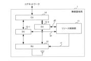
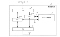
図2は、実施の形態1に係る無線基地局1の構成例を示すブロック図である。無線基地局1は、例えば、リソース制御部11と、RU12と、DU13-1及びDU13-2と、CU14とを含む。以下、DU13-1とDU13-2とが区別することが無い場合、DU13と記載される場合がある。また、DU13-1とDU13-2とは、それぞれ、「DU#1」と「DU#2」と記載される場合がある。
(Embodiment 1)
FIG. 2 is a block diagram showing a configuration example of the
CU14とDU13-1との間の接続、CU14とDU13-2との間の接続、リソース制御部11とDU13-1との間の接続、リソース制御部11とDU13-2との間の接続、RU12とDU13-1との間の接続、RU12とDU13-2との間の接続、及び、RU12とリソース制御部11との間の接続は、通信インターフェイスによって接続される。通信インターフェイスは、電気インターフェイスおよび光インターフェイスのいずれかであってよい。
Connection between
リソース制御部11は、例えば、Central Processing Unit(CPU)、Digital Signal Processor(DSP)、及びField Programmable Gate Array(FPGA)の少なくとも1つを搭載する装置である。リソース制御部11は、例えば、搭載されるCPU、DSP、及びFPGAの少なくとも1つにおいて動作する。リソース制御部11は、各DUに無線リソースを割り当てる。リソース制御部11によって割り当てられる無線リソースは、例えば、時間領域において規定されるリソース(時間リソース)、周波数領域において規定されるリソース(周波数リソース)、及び、時間リソースと周波数リソースとの組み合わせのいずれかである。
The
RU12は、例えば、CPU、DSP、及びFPGAの少なくとも1つを搭載する装置である。RU12は、例えば、搭載されるCPU、DSP、及びFPGAの少なくとも1つにおいて動作する。RU12は、radio frequency(RF)部及び物理レイヤ処理(PHY)機能の一部(Low-PHY)を有する。
The
DU13は、例えば、CPU、DSP、及びFPGAの少なくとも1つを搭載する装置である。DU13は、例えば、搭載されるCPU、DSP、及びFPGAの少なくとも1つにおいて動作する。DU13によって実行される動作は、RU12に含まれないPHY機能の一部(High-PHY)を含む。また、DU13によって実行される動作は、Medium Access Control(MAC)機能、及び、Radio Link Control(RLC)機能を含む。
The
CU14は、例えば、CPU、DSP、及びFPGAの少なくとも1つを搭載する装置である。CU14は、例えば、搭載されるCPU、DSP、及びFPGAの少なくとも1つにおいて動作する。CU14によって実行される動作は、Radio Resource Control(RRC)機能、Service Data Adaptation Protocol(SDAP)機能、及び、Packet Data Convergence Protocol(PDCP)機能を含む。 The CU 14 is, for example, a device equipped with at least one of a CPU, a DSP, and an FPGA. The CU 14 operates, for example, in at least one of a mounted CPU, DSP, and FPGA. Operations performed by the CU 14 include Radio Resource Control (RRC) functions, Service Data Adaptation Protocol (SDAP) functions, and Packet Data Convergence Protocol (PDCP) functions.
以下、リソース制御部11、RU12、DU13、及び、CU14のそれぞれについて説明する。なお、以下の例では、無線基地局1が端末(例えば、user equipment, UE)から上りリンク(UL)信号を受信する構成が示される。
Each of the
図3は、実施の形態1に係るリソース制御部11の構成例を示すブロック図である。リソース制御部11は、スケジューラ111と、第1割当結果通知部112と、割当結果生成部113と、第2割当結果通知部114と、を有する。
FIG. 3 is a block diagram showing a configuration example of the
スケジューラ111は、システムが使用可能な無線リソースを各DU13に割り当てるスケジューリングを行う。スケジューリング機能において使用するアルゴリズムは、Round Robinでもよいし、Proportional Fairnessでもよいし、その他のアルゴリズムでもよい。スケジューリングによって、DU13毎の無線リソース割当が決定される。なお、この無線リソース割当は、DU間の無線リソースの分配(又は比率)を制御すること、と理解されてもよい。
The
第1割当結果通知部112は、DU13-1と通信インターフェイスd1を通じて接続し、DU13-2と通信インターフェイスd2を通じて接続する。第1割当結果通知部112は、スケジューラ111によって決定された無線リソース割当の結果を取得し、通信インターフェイスd1を通じてDU13-1へ無線リソース割当の結果を通知し、通信インターフェイスd2を通じてDU13-2へ無線リソース割当の結果を通知する。
The first allocation
例えば、各DU(例えば、機能配置)が、それぞれ異なるサービス(例えば、異なるスライス)に対応する場合、サービスを利用する端末数、トラフィック、及び、サービスの種別の少なくとも1つに応じて、適応的に、DU間の無線リソース割当を変更してよい。そのため、スケジューラ111では、DU毎に無線リソース割当を定期的又は非定期的に更新してもよい。例えば、更新の頻度は、数100ms程度であってよい。この場合も、同様に、無線リソース割当を決定した後、第1割当結果通知部112は、例えば、各DUへ更新後の無線リソース割当を通知する。
For example, when each DU (e.g., functional arrangement) corresponds to a different service (e.g., different slice), the adaptive In addition, the radio resource allocation between DUs may be changed. Therefore, the
また、例えば、DUが、スライスによって実現され、スライスの数が適応的に変化する場合、DU間の無線リソース割当は、DUの数(スライスの数)によって変更されてもよい。 Further, for example, when a DU is realized by slices and the number of slices changes adaptively, radio resource allocation between DUs may be changed depending on the number of DUs (number of slices).
各DUに通知される情報には、無線リソースに関して、少なくとも当該DUにて使用可能な周波数帯域に関する情報および使用可能な時間情報が含まれてよい。例えば、DU13-1に通知される情報には、少なくともDU13-1にて使用可能な周波数帯域に関する情報および時間情報が含まれ、DU13-2に通知される情報には、少なくともDU13-2にて使用可能な周波数帯域に関する情報および時間情報が含まれてよい。 Regarding radio resources, the information notified to each DU may include at least information regarding a frequency band usable by the DU and information about available time. For example, the information notified to DU13-1 includes at least information regarding the frequency band usable by DU13-1 and time information, and the information notified to DU13-2 includes at least information regarding the frequency band usable by DU13-1. Information regarding available frequency bands and time information may be included.
割当結果生成部113は、RU12に通知する情報を生成する。割当結果生成部113は、スケジューラ111によって決定された無線リソース割当の結果を取得し、割当結果情報を生成する。割当結果情報には、各DUの識別子と、DU毎に使用可能な周波数帯域に関する情報および使用可能な時間情報とが含まれてよい。なお、割当結果情報の例については後述する。
The allocation
第2割当結果通知部114は、RU12と通信インターフェイスr1を通じて接続する。第2割当結果通知部114は、割当結果生成部113によって生成された割当結果情報をRU12へ通知する。割当結果情報は、制御情報の一例であり、どのDUがどの無線リソースを使うかを示す。
The second allocation
別言すると、リソース制御部11(例えば、「制御装置」と称されてもよい)は、複数のDU13に割り当てられるリソースに関する制御情報(例えば、割当結果情報)を決定する割当結果生成部113(例えば、「制御回路」と称されてもよい)を含む。また、リソース制御部11は、制御情報を、複数のDUのうち上りリンクの受信信号を転送するDUを決定する装置(例えば、RU)へ送信する第2割当結果通知部114(例えば、「送信回路」と称されてもよい)を含む。
In other words, the resource control unit 11 (for example, may be referred to as a “control device”) includes the allocation result generation unit 113 (for example, allocation result information) that determines control information (for example, allocation result information) regarding resources to be allocated to a plurality of
なお、DU13に通知する情報には、DUを識別するためのIDが含まれなくてよい。一方で、RU12に通知する情報には、DUを識別するためのIDが含まれてよい。
Note that the information notified to the
図4は、実施の形態1に係るRU12の構成例を示すブロック図である。RU12は、RF部121と、Analog/Digital(A/D)部122と、Fast Fourier transform(FFT)部123と、割当結果受信部124と、割当結果記憶部125と、出力先DU判定部126とを有する。なお、A/D部122と、FFT部123とは、纏めて、Low-PHY処理部127と称されてもよい。
FIG. 4 is a block diagram showing a configuration example of the
RF部121は、アンテナを介して受信した端末からのUL信号に対して、増幅処理、ダウンコンバート処理を施す。RF部121は、処理を施したUL信号をA/D部122へ出力する。
The
A/D部122は、RF部121から出力されたUL信号に対して、アナログ-デジタル変換(A/D変換)を施す。A/D部122は、A/D変換処理を施したUL信号をFFT部123へ出力する。
The A/
FFT部123は、A/D部122から出力されたUL信号に対して、FFT処理を施す。FFT部123は、FFT処理を施したUL信号を出力先DU判定部126へ出力する。
The
割当結果受信部124は、リソース制御部11と通信インターフェイスr1を通じて接続する。割当結果受信部124は、通信インターフェイスr1を通じてリソース制御部11から割当結果情報を受信する。割当結果受信部124は、割当結果情報を割当結果記憶部125へ記憶する。
The allocation
出力先DU判定部126は、割当結果記憶部125に記憶された割当結果情報に基づいて、FFT部123から出力されるUL信号の出力先のDU13を判定する。そして、出力先DU判定部126は、判定結果に基づいて、UL信号をDU13(DU13-1又はDU13-2)へ出力する。なお、「出力先」は、「送付先」、「宛先」、「転送先」等の他の呼称に置き換えられてよい。また、出力先DU判定部126における判定の例については後述する。
The output destination
別言すると、RU12(例えば、「制御装置」と称されてもよい)は、複数のDU13に割り当てるリソースに関する制御情報(例えば、割当結果情報)を受信する割当結果受信部124(例えば、「受信回路」と称されてもよい)を含む。また、RU12は、制御情報に基づいて、複数のDU13のうち上りリンクの受信信号を転送するDU13を決定する出力先DU判定部126(例えば、「制御回路」と称されてもよい)を含む。
In other words, the RU 12 (for example, may be referred to as a "control device") has an allocation result receiving unit 124 (for example, a "receiving circuit). The
図5は、実施の形態1に係るDU13及びCU14の構成例を示すブロック図である。DU13のそれぞれは、例えば、REデマッピング(RE demapping)部131と、チャネル推定(Channel Estimation)部132と、復調(Demodulation)部133と、デスクランブリング(Descrambling)部134と、復号(Decoding)部135と、MAC部136と、RLC部137と、割当結果受信部138と、割当結果記憶部139と、を有する。
FIG. 5 is a block diagram showing a configuration example of the
REデマッピング部131は、RU12から受信したUL信号において、端末が所定のリソースエレメント(RE)にマッピングした信号に対して、デマッピング処理を施す。例えば、UL信号に対するデマッピング処理によって、リファレンス信号(例えば、demodulation reference signal(DMRS))と、データ信号とが抽出される。
The
チャネル推定部132は、UL信号に含まれるリファレンス信号を用いて、チャネル推定を行う。
The
復調部133は、UL信号に含まれるデータ信号に対して、復調処理を行う。例えば、データ信号の変調に使用された変調方式(例えば、Quadrature Phase shift Keying(QPSK)、16Quadrature Amplitude Modulation(QAM)、64QAM、及び、256QAM等)に応じた復調処理が実行されてよい。
The
デスクランブリング部134は、復調処理が施されたデータ信号に対して、デスクランブリング処理を施す。
The
復号部135は、デスクランブリング処理が施されたデータ信号に対して、復号処理を施す。復号処理が施され、復号部135から出力される信号は、例えば、トランスポートブロックの形式を有する。
The
MAC部136は、割当結果に基づいて、端末から送信される信号の受信に用いるパラメータ(以下「受信パラメータ」と称することがある)を生成する。受信パラメータには、例えば、受信処理に関する周波数帯域および時間情報といった情報が含まれてよい。受信パラメータには、ORANの標準規格(ORAN-WG4.CUS.0-v02.00, P60)に記載される受信パラメータが含まれてよい。
Based on the assignment result, the
MAC部136は、受信パラメータ及び復号部135から取得するトランスポートブロックに含まれるヘッダに記載の情報(例えば、パケット情報)に基づいて、トランスポートブロックの分割を行い、分割後のブロックをRLC部137へ出力する。なお、RLC部137へ出力される信号のブロックは、MAC SDU(service data unit)と称されてよい。
The
RLC部137は、MAC部136から取得するMAC SDUに含まれるヘッダに記載の情報に基づいて、パケット分割及び再構成を行う。パケット分割及び再構成を行った後の信号のブロックは、RLC SDUと称されてよい。RLC部137は、RLC SDUをCU14へ出力する。
The
割当結果受信部138は、リソース制御部11と通信インターフェイスd1を通じて接続する。割当結果受信部138は、通信インターフェイスd1を通じてリソース制御部11から割当結果を受信する。割当結果受信部138は、割当結果を割当結果記憶部139に記憶する。
The allocation
CU14は、DU13-1とDU13-2とのそれぞれから信号(例えば、RLC SDU形式の信号のブロック)を受信する。CU14は、DU13-1と接続するPDCP部141及びRRC/SDAP部142と、DU13-2と接続するPDCP部141及びRRC/SDAP部142と、を有する。
PDCP部141は、暗号化されたデータの解読及び/又は圧縮されたデータの展開を行い、PDCP SDUをRRC/SDAP部142へ出力する。
The
RRC/SDAP部142は、PDCP部141から取得するデータ(PDCP SDU)に記載された情報に基づいて、例えば、無線基地局と接続する端末との設定変更、ハンドオーバー処理、及び、優先制御に従ったコアネットワークへのデータ転送などを行う。
Based on the information written in the data (PDCP SDU) acquired from the
次に、割当結果情報と割当結果情報に基づく出力先のDUの決定の例を説明する。 Next, an example of determining the output destination DU based on the allocation result information and the allocation result information will be described.
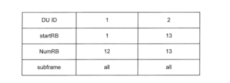
図6Aは、割当結果情報の第1の例を示す図である。図6Bは、図6Aに示した割当結果情報の第1の例に基づく出力先DUの決定の例を示す図である。 FIG. 6A is a diagram showing a first example of allocation result information. FIG. 6B is a diagram illustrating an example of determining an output destination DU based on the first example of the allocation result information illustrated in FIG. 6A.
図6Aに示す割当結果情報は、例えば、リソース制御部11からRU12へ通知される。図6Aに示す割当結果情報は、DU13を識別するための識別子(ID)(DU ID)と、各DU13において使用可能なリソースブロック(RB)の開始インデックスと、使用可能なRB数と、使用可能なサブフレームに関する情報とを含む。
The allocation result information shown in FIG. 6A is notified from the
例えば、RU12が、予めDU IDとDUの送り先情報(例えば、IPアドレス)との対応付けを記憶することによって、割当結果情報におけるDU IDとDU13とが紐付けられてもよい。あるいは、リソース制御部11にて生成される割当結果情報が、DU IDと併せて、該当するDUの送り先情報を含んでもよい。なお、図6Aでは、DU IDが、DU毎に設定された番号の例を示すが、DU IDは、Internet Protocol(IP)アドレスであってもよい。
For example, the DU ID and the
例えば、図6Aに示す割当結果情報は、DUのIDが「1」に該当するDU13(DU#1)に対しては、割当可能なRBのうち、インデックス1~12に対応するRBが割り当てられることを示す。また、図6Aに示す割当結果情報は、DUのIDが「2」に該当するDU13(DU#2)に対しては、割当可能なRBのうち、インデックス13~25に対応するRBが割り当てられることを示す。また、図6Aに示す割当結果情報は、DU#1及びDU#2に対して、全てのサブフレームが割り当てられる、つまり、全てのサブフレームにおいて受信が可能であることを示す。
For example, in the allocation result information shown in FIG. 6A, for DU13 (DU#1) whose DU ID corresponds to "1", RBs corresponding to
出力先DU判定部126は、割当結果情報に基づいて、出力先のDUを判定し、判定した出力先DUに信号を振り分けて出力する。
The output destination
図6Bには、出力先DU判定部126における出力先DUへの出力の例が示される。
FIG. 6B shows an example of output to the output destination DU by the output destination
出力先DU判定部126は、例えば、各サブフレームにおいて、インデックス1~12に対応する周波数帯域の信号を抽出して(切り出して)、DU#1へ出力し、インデックス13~25に対応する周波数帯域の信号を抽出して(切り出して)、DU#2へ出力する。
For example, the output destination
図7Aは、割当結果情報の第2の例を示す図である。図7Bは、図7Aに示した割当結果情報の第2の例に基づく出力先のDUの決定の例を示す図である。 FIG. 7A is a diagram showing a second example of allocation result information. FIG. 7B is a diagram illustrating an example of determining the output destination DU based on the second example of the allocation result information illustrated in FIG. 7A.
図7Aに示す割当結果情報は、図6Aの例と同様に、DU13のDU IDと、各DU13において使用可能なリソースブロック(RB)の開始インデックスと、使用可能なRB数と、使用可能なサブフレームに関する情報とを含む。
As in the example of FIG. 6A, the allocation result information shown in FIG. 7A includes the DU ID of
例えば、図7Aに示す割当結果情報は、DUのIDが「1」に該当するDU13(DU#1)に対しては、インデックス0~9に対応する10サブフレームのうち、インデックス0、2、4、6、8に対応するサブフレーム(偶数サブフレーム)が割り当てられることを示す。また、図7Aに示す割当結果情報は、DUのIDが「2」に該当するDU13(DU#2)に対しては、インデックス0~9に対応する10サブフレームのうち、インデックス1、3、5、7、9に対応するサブフレーム(奇数サブフレーム)が割り当てられることを示す。また、図7Aに示す割当結果情報は、DU#1及びDU#2に対して、割当可能なRBのうち、インデックス1~25に対応する周波数帯域が割り当てられることを示す。
For example, the allocation result information shown in FIG. 7A indicates that for DU13 (DU#1) whose DU ID corresponds to "1", among the 10 subframes corresponding to
出力先DU判定部126は、割当結果情報に基づいて、出力先のDUを判定し、判定した出力先のDUに信号を出力する。
The output destination
図7Bには、出力先DU判定部126による出力先DUへの出力例が示される。
FIG. 7B shows an example of output to the output destination DU by the output destination
出力先DU判定部126は、例えば、インデックス0及び2に対応するサブフレームの信号を抽出して(切り出して)、DU#1へ出力し、インデックス1に対応するサブフレームの信号を抽出して(切り出して)、DU#2へ出力する。なお、出力先DU判定部126から出力される信号は、それぞれ、インデックス1~25の周波数帯域の信号である。
For example, the output destination
なお、図6B及び図7Bでは、FFT部123からの出力結果(FFT出力)が、各DU13へ出力される例が示されるが、本開示はこれに限定されない。例えば、時間領域のUL信号が、割当結果情報に基づいて、各DUへ出力されてよい。
Note that although FIGS. 6B and 7B show an example in which the output result (FFT output) from the
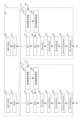
図8は、実施の形態1に係る無線基地局1と端末とのシーケンス図である。図8には、端末#1と、端末#2と、RU12と、リソース制御部11と、DU#1と、DU#2と、CU14とにおける処理及び情報の伝達の手順が示される。
FIG. 8 is a sequence diagram of the
例えば、リソース制御部11は、2つのDU#1及びDU#2に対する無線リソースの割り当て(別言すると、スケジューリング)を実行する(S100)。リソース制御部11は、スケジューリングの結果(無線リソース割当の結果)を、DU#1に通知する(S101)。また、リソース制御部11は、スケジューリングの結果(無線リソース割当の結果)をDU#2に通知する(S102)。また、リソース制御部11は、割当結果情報を生成する(S103)。そして、リソース制御部11は、割当結果情報をRU12へ通知する(S104)。S101、S102、及び、S104は、順序が入れ替えられもよいし、並行して実施されてもよい。
For example, the
DU#1は、リソース制御部11から無線リソース割当の結果を受信し、受信した結果(リソース割当情報)に基づいて、例えば端末#1に対する無線リソースのスケジューリングを行う(S105)。例えば、DU#1は、リソース制御部11によってDU#1に割り当てられた無線リソースにおいて端末#1に割り当てる無線リソースを決定する。
そして、DU#1は、端末#1への割り当てを決定した無線リソースを示すUL Grant情報を端末#1へ通知する(S106)。なお、端末#1への通知は、RU12を介して実施されてよい。
Then,
DU#2は、リソース制御部11から受信したリソース割当情報に基づいて、例えば端末#2に対する無線リソースのスケジューリングを行う(S107)。例えば、DU#2は、リソース制御部11によってDU#2に割り当てられた無線リソースにおいて端末#2に割り当てる無線リソースを決定する。
そして、DU#2は、端末#2への割り当てを決定した無線リソースを示すUL Grant情報を端末#2へ通知する(S108)。なお、端末#2への通知は、RU12を介して実施されてよい。端末#1及び端末#2に対する通知(S106及びS108)の順序はどちらが先でもよいし、並行して実施されてもよい。
Then,
端末#1は、DU#1から受信したUL Grant情報が示す無線リソースにおいて、データ信号を送信する(S109)。
端末#2は、DU#2から受信したUL Grant情報が示す無線リソースにおいて、データ信号を送信する(S110)。端末#1及び端末#2によるデータ送信(S109及びS110)の順序は、互いに入れ替わることもあるし同時の場合もあり得る。
RU12は、S109にて端末#1が送信したデータ信号と、S110にて端末#2が送信したデータ信号とを受信し、受信したデータ信号に対するRF処理及びLow-PHY処理を行う(S111)。
The
RU12は、リソース制御部11から受信した割当結果情報に基づいて、ULの受信データ信号の出力先DUを判定する(S112)。RU12は、判定結果に基づいて、受信したデータ信号のうち、DU#1に対するデータ信号(対象データ信号)をDU#1に出力し(S113)、DU#2に対するデータ信号をDU#2に出力する(S114)。例えば、図6A、図6Bのような周波数によるDUの割当が行われる場合において、RU12は、ULの受信データ信号をRBインデックス13で受信した場合には、図6Aの割当結果情報に基づき、DU#2を出力先DUと判定する。なお、S113の処理とS114の処理とは、順序が互いに入れ替わってもよいし並行して実施されてもよい(時間的に同時でもよいし一部が重複してもよい)。
The
DU#1は、RU12から受信したデータに対して、High-PHY処理、MAC処理、及び、RLC処理を施す(S115)。そして、DU#1は、これらの処理を施したデータをCU14に出力する(S116)。
DU#2は、RU12から受信したデータに対して、High-PHY処理、MAC処理、及び、RLC処理を施す(S117)。そして、DU#2は、これらの処理を施したデータをCU14に出力する(S118)。
なお、図7では、端末がRU12へ送信する信号(UL信号)が、データ信号である例を示したが、UL信号は、制御情報を含む制御信号であってもよい。
Note that although FIG. 7 shows an example in which the signal (UL signal) transmitted by the terminal to the
以上のように、本実施の形態1では、リソース制御部11が、割当結果情報をRU12へ出力し、RU12が、割当結果情報に基づいて、UL信号の出力先のDU13を判定する。そして、RU12が、判定結果に応じて、UL信号を適切なDU13へ出力する。この構成により、UL信号の不要な出力(転送)を抑制できるため、フロントホールの帯域が過剰に(不必要に)消費されることを回避でき、UL信号のフロントホールにおける伝送効率を向上できる。
As described above, in the first embodiment, the
また、DU間のリソース割当が変更された場合でも、リソース制御部11が、割当結果情報を更新し、RU12へ更新した割当結果情報を通知できるため、リソース割当の変更に追従して効率的なデータ転送を実現できる。
In addition, even when the resource allocation between DUs is changed, the
また、実施の形態1では、DUに機能が追加されないため、DUの機能を簡素化できる。例えば、DUに該当する機能を有する機器を外部のベンダーから購入した場合でも、当該DUを含む無線基地局1が実現できる。例えば、無線基地局1は複数のDUを有するため、DUの機能を簡素化することによって、低コストな無線基地局を実現できる。
Further, in the first embodiment, since no functions are added to the DU, the functions of the DU can be simplified. For example, even if a device having a function corresponding to a DU is purchased from an external vendor, a
また、実施の形態1の図6A、図6Bに示す例では、DU間のリソース割り当てにおいて、周波数リソースによる割り当てが行われる。例えば、DU間で周波数リソースによる割り当てが行われることによって、データ容量が相対的に小さいが、低遅延なサービスに対応するDUへ適切なリソース割り当てが実施できる。また、このような周波数リソースの割り当てに対しても、UL信号のフロントホールにおける伝送効率を向上できる。 Furthermore, in the example shown in FIGS. 6A and 6B of the first embodiment, frequency resource allocation is performed in resource allocation between DUs. For example, by performing frequency resource allocation between DUs, appropriate resource allocation can be performed to DUs that have relatively small data capacity but support low-delay services. Moreover, the transmission efficiency of the UL signal in the fronthaul can be improved also with respect to such frequency resource allocation.
また、実施の形態1の図7A、図7Bに示す例では、DU間のリソース割り当てにおいて、時間リソースによる割り当てが行われる。例えば、DU間で時間リソースによる割り当てが行われることによって、タイムクリティカル(時間的なスケジューリングが要求される)なサービスやバースト的な伝送に対応するDUへ適切なリソース割り当てが実施できる。また、このような時間リソースの割り当てに対しても、UL信号のフロントホールにおける伝送効率を向上できる。 Furthermore, in the example shown in FIGS. 7A and 7B of the first embodiment, resource allocation between DUs is performed using time resources. For example, by allocating time resources between DUs, it is possible to appropriately allocate resources to DUs that support time-critical services (requiring temporal scheduling) or burst transmissions. Moreover, the transmission efficiency of UL signals in the fronthaul can also be improved with respect to such time resource allocation.
なお、本実施の形態1では、リソース制御部11が、スケジューラ111、第1割当結果通知部112、割当結果生成部113、及び、第2割当結果通知部114を含み、CU14、DU13と別の要素(装置)である例を説明したが、本開示はこれに限定されない。例えば、リソース制御部11は、CU14又はDU13に含まれてもよい。また、リソース制御部11が、スケジューラ111と、第1割当結果通知部112とを含む第1のリソース制御部と、割当結果生成部113と、第2割当結果通知部114とを含む第2のリソース制御部とに分割されてもよい。第2のリソース制御部は、第1のリソース制御部から情報を受信する受信部を含んでもよい。
Note that in the first embodiment, the
また、各DU13の機能は、DU13ごとに異なるハードウェアに実装される例を示したが、例えば、同一のサーバのCPUで実行される複数のソフトウェアのように、同一のハードウェア内の異なるソフトウェアとして実行されてもよい。また、CU14の機能は、同一のハードウェアに実装されるとしたが、異なる別々のハードウェアにて実行されてもよい。
In addition, although an example has been shown in which the functions of each
なお、本実施の形態1に示した、CU14、DU13、RU12に搭載される機能は、一例であり、これらに限定されるものではない。例えば、ビームフォーミング及びMIMO(multiple-input and multiple-output)通信を行うための機能が含まれてもよい。
Note that the functions installed in the
また、本実施の形態1では、無線リソースが、時間リソース、周波数リソース、及び、時間リソースと周波数リソースとの組み合わせである例を示したが、本開示はこれに限定されない。例えば、ビームフォーミング及びMIMO通信の少なくとも1つにより、複数の信号が空間多重される場合、無線リソースは、空間リソース(例えば、空間的に直交するビーム、及び、空間ストリームの少なくとも1つ)が含まれてよい。
Furthermore, in
また、本実施の形態1において、割当結果情報に含まれる、時間リソースに関する情報(例えば、各DUに割り当てられるサブフレームに関する情報)と、周波数リソースに関する情報(各DUに割り当てられるRBに関する情報)とに基づいて、UL信号が振り分けられる例を示したが、本開示はこれに限定されない。例えば、DU間のスケジューリングが、時間リソースと周波数リソースとの組み合わせによって実行される場合、時間リソースに関する情報と周波数リソースに関する情報との少なくとも一方に基づいて、UL信号が振り分けられてもよい。 In addition, in the first embodiment, information regarding time resources (for example, information regarding subframes allocated to each DU) and information regarding frequency resources (information regarding RBs allocated to each DU) included in the allocation result information. Although an example has been shown in which UL signals are distributed based on the following, the present disclosure is not limited thereto. For example, when scheduling between DUs is performed using a combination of time resources and frequency resources, UL signals may be distributed based on at least one of information regarding time resources and information regarding frequency resources.
例えば、DUのIDが「1」に該当するDU13(DU#1)に対して、偶数サブフレームの中でインデックス1~12に対応するRBが割り当てられる場合、RU12の出力先DU判定部126は、偶数サブフレームそれぞれに含まれ、インデックス1~12に対応するRBのUL信号をDU#1に出力する。
For example, when RBs corresponding to
あるいは、DU#1に上述のリソースが割り当てられた場合に、RU12の出力先DU判定部126は、偶数サブフレームのUL信号をDU#1に出力してもよい。これにより、例えばRUにFFT処理が含まれず、周波数領域でのUL信号の振り分けが困難な場合であっても、時間領域でのUL信号の振り分けにより、UL信号の不要な出力(転送)を抑制でき、UL信号のフロントホールの伝送効率を向上できる。
Alternatively, when the above-mentioned resources are allocated to
あるいは、DU#1に上述のリソースが割り当てられた場合に、出力先DU判定部126は、各サブフレームのインデックス1~12に対応するRBのUL信号をDU#1に出力してもよい。これにより、例えば、サブフレーム毎に出力先のDUを切り替えることを回避できるため、UL信号の振り分けのための制御を簡易にできる。
Alternatively, when the above-described resources are allocated to
(実施の形態2)
図9は、実施の形態2に係る無線基地局2の構成例を示すブロック図である。なお、図9において、図2と同様の構成については同一の符番を付す。
(Embodiment 2)
FIG. 9 is a block diagram showing a configuration example of the
無線基地局2は、例えば、リソース制御部21と、RU22と、DU23-1及びDU23-2と、CU14とを含む。
The
図9に示す無線基地局2は、図2に示した無線基地局1に比して、RU22とリソース制御部21とが接続されない点が異なる。
The
CU14とDU23-1との間の接続、CU14とDU23-2との間の接続、リソース制御部21とDU23-1との間の接続、リソース制御部21とDU23-2との間の接続、RU22とDU23-1との間の接続、及び、RU22とDU23-2との間の接続は、通信インターフェイスによって接続される。通信インターフェイスは、電気インターフェイスおよび光インターフェイスのいずれかであってよい。
Connection between
リソース制御部21は、図2に示したリソース制御部11と同様に、装置に搭載されるCPU、DSP、及びFPGAの少なくとも1つにおいて動作する。
Similar to the
RU22及びDU23は、それぞれ、図2に示したRU12及びDU13と同様に、装置に搭載されるCPU、DSP、及びFPGAの少なくとも1つにおいて動作する。
The
以下、リソース制御部21、RU22、及び、DU23について説明する。なお、以下の例では、無線基地局2が端末から上りリンク(UL)信号を受信する構成が示される。
The
図10は、実施の形態2に係るリソース制御部21の構成例を示すブロック図である。
FIG. 10 is a block diagram showing a configuration example of the
リソース制御部21は、スケジューラ211と、第1割当結果通知部212と、を有する。
The
図10に示すリソース制御部21は、図3に示したリソース制御部11に比して、図3に示した割当結果生成部113と第2割当結果通知部114とを含まない点が異なる。
The
スケジューラ211は、スケジューラ111と同様に、システムが使用可能な無線リソースを各DU23に割り当てるスケジューリングを行う。スケジューリングの結果、DU23毎の無線リソース割当が決定される。
The
第1割当結果通知部212は、DU23-1と通信インターフェイスd1を通じて接続し、DU23-2と通信インターフェイスd2を通じて接続する。第1割当結果通知部212は、スケジューラ211によって決定された無線リソース割当の結果を受信し、通信インターフェイスd1を通じてDU23-1へ無線リソース割当の結果を通知し、通信インターフェイスd2を通じてDU23-2へ無線リソース割当の結果を通知する。
The first allocation
図11は、実施の形態2に係るDU23及びCU14の構成例を示すブロック図である。なお、図11において、図5と同様の構成については、同一の符番を付す。
FIG. 11 is a block diagram showing a configuration example of the DU 23 and
図11に示すDU23(23-1及び23-2)は、図5に示したDU13(13-1及び13-2)に比して、割当結果生成部213と第2割当結果通知部214とを追加的に含む点が異なる。 DU23 (23-1 and 23-2) shown in FIG. 11 differs from DU13 (13-1 and 13-2) shown in FIG. The difference is that it additionally includes
割当結果生成部213は、RU22に通知する情報を生成する。割当結果生成部213は、割当結果記憶部139から割当結果を取得し、割当結果情報を生成する。割当結果情報には、各DUの識別子と、DU毎に使用可能な周波数帯域に関する情報および使用可能な時間情報とが含まれてよい。なお、割当結果情報の例については後述する。
The allocation
第2割当結果通知部214は、RU22と接続する。第2割当結果通知部214は、割当結果生成部213によって生成される割当結果情報をRU22へ通知する。
The second allocation
図12は、実施の形態2に係るRUの構成例を示すブロック図である。なお、図12において、図4と同様の構成については、同一の符番を付す。 FIG. 12 is a block diagram showing a configuration example of an RU according to the second embodiment. Note that in FIG. 12, the same components as in FIG. 4 are given the same reference numerals.
図12に示すRU22は、図4に示したRU12に比して、割当結果受信部124が、リソース制御部11に代えてDU23から割当結果情報を受信する点が異なる。
The
例えば、割当結果受信部124は、DU23-1及びDU23-2からそれぞれ割当結果情報を受信する。
For example, the allocation
次に、本実施の形態2における、割当結果情報と割当結果情報に基づく出力先のDUの決定の例を説明する。 Next, an example of determining the output destination DU based on the allocation result information and the allocation result information in the second embodiment will be described.
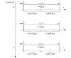
図13Aは、割当結果情報の第3の例を示す図である。図13Bは、図13Aに示した割当結果情報の第3の例に基づく出力先のDUの決定の例を示す図である。 FIG. 13A is a diagram showing a third example of allocation result information. FIG. 13B is a diagram illustrating an example of determining the output destination DU based on the third example of the allocation result information illustrated in FIG. 13A.
図13Aに示す割当結果情報は、割当結果情報#1と割当結果情報#2とを含む。割当結果情報#1は、DU#1からRU22へ通知される。割当結果情報#1は、DU#1のIDと、DU#1において使用可能なRBの開始インデックスと、使用可能なRB数と、使用可能なサブフレームに関する情報とを含む。割当結果情報#2は、DU#2からRU22へ通知される。割当結果情報#2は、DU#2のIDと、DU#2において使用可能なRBの開始インデックスと、使用可能なRB数と、使用可能なサブフレームに関する情報とを含む。
The allocation result information shown in FIG. 13A includes allocation
図6Aと図13Aとの関係について説明すると、図6Aに示した割当結果情報は、DU#1とDU#2とのそれぞれに対する割当結果に関する情報であり、リソース制御部11からRU12に通知される。一方で、図13Aに示した割当結果情報の中で、割当結果情報#1は、DU#1に対する割当結果に関する情報であり、DU#1からRU22に通知され、割当結果情報#2は、DU#2に対する割当結果に関する情報であり、DU#2からRU22に通知される。
To explain the relationship between FIG. 6A and FIG. 13A, the allocation result information shown in FIG. 6A is information regarding the allocation results for each of
図12において、出力先DU判定部126は、割当結果情報に基づいて、出力先DUを判定し、信号を出力する。
In FIG. 12, the output destination
図13Bには、出力先DU判定部126における出力先のDUへの出力の例が示される。
FIG. 13B shows an example of output to the output destination DU by the output destination
出力先DU判定部126は、例えば、3つのサブフレーム#0~#2のそれぞれにおいて、インデックス1~12に対応する周波数帯域の信号を、DU#1へ出力し、インデックス13~25に対応する周波数帯域の信号を、DU#2へ出力する。
For example, the output destination
図14は、実施の形態2に係る無線基地局と端末とのシーケンス図である。図14において、図8と同様の処理については、同一の符番を付す。 FIG. 14 is a sequence diagram of a wireless base station and a terminal according to the second embodiment. In FIG. 14, processes similar to those in FIG. 8 are given the same reference numerals.
図14に示すシーケンスでは、リソース制御部21が割当結果情報をRU22へ通知する代わりに(図8のS104参照)、DUが割当結果情報を通知する。
In the sequence shown in FIG. 14, instead of the
例えば、図14では、DU#1が、割当結果情報を生成し(S201)、割当結果情報をRU22へ通知する(S203)。また、DU#2が、割当結果情報を生成し(S202)、割当結果情報をRU22へ通知する(S204)。ここで、DU#1が通知する割当結果情報と、DU#2が通知する割当結果情報とは、図13Aに例示したように、互いに異なってよい。また、RU22への通知(S203及びS204)の順序はどちらが先でもよいし、並行して実施されてもよい。
For example, in FIG. 14,
以上のように、本実施の形態2では、DU23が、リソース制御部21から受信した情報に基づいて生成した割当結果情報をRU22へ出力し、RU22が、割当結果情報に基づいて、UL信号の出力先DUを判定する。そして、RU22が、判定結果に応じて、UL信号を適切なDUへ出力する。この構成により、UL信号の不要な出力(転送)を抑制できるため、フロントホールの帯域が過剰に(不必要に)消費されることを回避でき、UL信号のフロントホールにおける伝送効率を向上できる。
As described above, in the second embodiment, the DU 23 outputs the allocation result information generated based on the information received from the
また、DU間のリソース割当が変更された場合でも、RU22は、更新した割当結果情報を受信できるため、リソース割当の変更に追従して効率的なデータ転送を実現できる。
Further, even when the resource allocation between DUs is changed, the
また、本実施の形態2では、DUとRUとの間を接続する通信インターフェイスにおいて、RUへ割当結果情報を通知できるため、リソース制御部とRUとの間の通信インターフェイスを敷設することを回避できる。 Furthermore, in the second embodiment, the allocation result information can be notified to the RU in the communication interface that connects the DU and the RU, so it is possible to avoid installing a communication interface between the resource control unit and the RU. .
なお、本実施の形態2では、2つのDUが同様の構成である例を示したが、本開示はこれに限定されない。例えば、実施の形態1に示したDU(例えば、DU13)と、実施の形態2に示すDU(例えば、DU23)とが混在してもよい。この場合、実施の形態1に示したDUはRUへ割当結果情報を通知しないため、RUは、DUから割当結果情報を取得するのではなく、リソース制御部から割当結果情報を取得してよい。RUがリソース制御部から割当結果情報を取得する場合、DU23が有する割当結果生成部213及び第2割当結果通知部214の機能は、停止されてよい。
Note that although the second embodiment shows an example in which two DUs have the same configuration, the present disclosure is not limited to this. For example, the DU shown in Embodiment 1 (for example, DU13) and the DU shown in Embodiment 2 (for example, DU23) may coexist. In this case, since the DU shown in
(実施の形態3)
図15は、実施の形態3に係る無線基地局3の構成例を示すブロック図である。なお、図15において、図2又は図9と同様の構成については同一の符番を付す。
(Embodiment 3)
FIG. 15 is a block diagram showing a configuration example of the
無線基地局3は、例えば、リソース制御部31と、RU32と、DU13-1及びDU13-2と、CU14と、出力ユニット35とを含む。
The
リソース制御部31と出力ユニット35との間の接続、リソース制御部31とDU13-1との間の接続、リソース制御部31とDU13-2との間の接続、出力ユニット35とRU32との間の接続、出力ユニット35とDU13-1との間の接続、及び、出力ユニット35とDU13-2との間の接続は、通信インターフェイスによって接続される。通信インターフェイスは、電気インターフェイスおよび光インターフェイスのいずれかであってよい。
Connection between the
図16は、実施の形態3に係るリソース制御部31の構成例を示すブロック図である。なお、図16において、図3と同様の構成については、同一の符番を付す。
FIG. 16 is a block diagram showing a configuration example of the
図16に示すリソース制御部31は、図3に示したリソース制御部11に比して、図3に示した第2割当結果通知部114によって割当結果情報が出力ユニット35へ通知される点が異なる。
The
例えば、第2割当結果通知部114は、出力ユニット35と通信インターフェイスc1を通じて接続する。第2割当結果通知部114は、割当結果生成部113によって生成される割当結果情報を出力ユニット35へ通知する。
For example, the second allocation
図17は、実施の形態3に係るRU32の構成例を示すブロック図である。なお、図17において、図4と同様の構成については、同一の符番を付す。
FIG. 17 is a block diagram showing a configuration example of the
図17に示すRU32は、図4に示したRU12に比して、図4に示した割当結果受信部124、割当結果記憶部125、及び、出力先DU判定部126を含まず、また、FFT部123によってFFT処理を施されたUL信号が出力ユニット35へ出力される点が異なる。
The
図18は、実施の形態3に係る出力ユニット35の構成例を示すブロック図である。
FIG. 18 is a block diagram showing a configuration example of the
出力ユニット35は、割当結果受信部351と、割当結果記憶部352と、出力先DU判定部353と、を含む。
The
割当結果受信部351は、リソース制御部31と通信インターフェイスc1を通じて接続する。割当結果受信部351は、リソース制御部31から割当結果情報を受信する。割当結果受信部351は、割当結果情報を割当結果記憶部352へ記憶する。
The allocation
出力先DU判定部353は、割当結果記憶部352に記憶された割当結果情報に基づいて、RU32から出力されるUL信号の出力先のDU13を判定する。そして、出力先DU判定部353は、判定結果に基づいて、UL信号をDU13(DU13-1又はDU13-2)へ出力する。なお、出力先DU判定部353における判定の例については、実施の形態1の出力先DU判定部126における判定の例と同様でよい。
The output destination
図19は、実施の形態3に係るDU13及びCU14の構成例を示すブロック図である。
FIG. 19 is a block diagram showing a configuration example of the
図19に示すDU13及びCU14は、図5に示したDU13及びCU14に比して、REデマッピング部131が、RU12に代えて出力ユニット35からUL信号を受信する点が異なる。
The
図20は、実施の形態3に係る無線基地局3と端末とのシーケンス図である。図20において、図8と同様の処理については、同一の符番を付す。
FIG. 20 is a sequence diagram of the
図20に示すシーケンスでは、リソース制御部31が、割当結果情報を出力ユニット35へ通知する(S301)。
In the sequence shown in FIG. 20, the
RU32は、受信したデータを出力ユニット35へ出力する(S302)。
The
出力ユニット35は、受信したデータの出力先のDUを判定する(S303)。出力ユニット35は、判定結果に基づいて、受信したデータのうち、DU#1に対するデータ(対象データ)をDU#1に出力し(S304)、DU#2に対するデータをDU#2に出力する(S305)。なお、S304の処理とS305の処理とは、時間的に同時又は一部が重複してもよい。
The
以上のように、本実施の形態3では、リソース制御部31が、割当結果情報を、RU32とDU13との間に設けられた出力ユニット35へ出力し、出力ユニット35が、割当結果情報に基づいて、UL信号の出力先のDU13を判定する。そして、出力ユニット35が、判定結果に応じて、UL信号を適切なDU13へ出力する。この構成により、UL信号の不要な出力(転送)を抑制できるため、フロントホールの帯域が過剰に(不必要に)消費されることを回避でき、UL信号のフロントホールの伝送効率を向上できる。
As described above, in the third embodiment, the
また、DU間のリソース割当が変更された場合でも、リソース制御部31が、割当結果情報を更新し、出力ユニット35へ更新した割当結果情報を通知できるため、リソース割当の変更に追従して効率的なデータ転送を実現できる。
Furthermore, even when the resource allocation between DUs is changed, the
また、本実施の形態3では、出力ユニット35が、出力先のDU13を判定し、判定結果に応じて、UL信号を適切なDU13へ出力する構成を採る。そのため、RU32の機能を簡素化でき、例えば、RU32に該当する機能を有する機器を外部のベンダーから購入した場合など、RUに機能の実装が困難な場合でも、出力ユニット35を接続することによって、UL信号のフロントホールの伝送効率を向上できる。
Further, in the third embodiment, the
なお、本実施の形態3では、割当結果情報がリソース制御部から出力ユニットに通知される例を示したが、本開示はこれに限定されない。例えば、実施の形態2に示した例と同様に、割当結果情報がDUから出力ユニットに通知されてもよい。例えば、割当結果情報がDUから出力ユニットに通知される場合、通信インターフェイスc1は省略されてよい。
Note that although the third embodiment shows an example in which allocation result information is notified from the resource control unit to the output unit, the present disclosure is not limited to this. For example, similar to the example shown in
また、本実施の形態3では、リソース制御部と出力ユニットとが、互いに別の装置である例を示したが、本開示はこれに限定されない。例えば、リソース制御部が、RUとDUとの間に接続される出力ユニットに搭載されてもよい。この構成では、例えば、リソース制御部からDUへの割当結果の通知が、DUと出力ユニットとの間の通信インターフェイスを介して行われるため、通信インターフェイスd1及び通信インターフェイスd2が省略できる。また、リソース制御部からRUへの通知が、RUと出力ユニットとの間の通信インターフェイスを介して行われるため、通信インターフェイスc1が省略できる。 Further, in the third embodiment, an example was shown in which the resource control unit and the output unit are separate devices, but the present disclosure is not limited to this. For example, the resource control unit may be installed in an output unit connected between the RU and DU. In this configuration, for example, the resource control unit notifies the DU of the allocation result via the communication interface between the DU and the output unit, so the communication interface d1 and the communication interface d2 can be omitted. Furthermore, since notification from the resource control unit to the RU is performed via the communication interface between the RU and the output unit, the communication interface c1 can be omitted.
(実施の形態4)
図21は、実施の形態4に係る無線基地局4の構成例を示すブロック図である。なお、図21において、図9と同様の構成については、同一の符番を付す。
(Embodiment 4)
FIG. 21 is a block diagram showing a configuration example of the
無線基地局4は、例えば、リソース制御部21と、RU42と、DU43-1及びDU43-2と、CU14とを含む。
The
図21に示す無線基地局4は、図2に示した無線基地局1に比して、RU42とリソース制御部21とが接続されない点が異なる。別言すると、実施の形態4において、RU42は、リソース制御部21による制御を受けなくてよい。
The
CU14とDU43-1との間の接続、CU14とDU43-2との間の接続、リソース制御部21とDU43-1との間の接続、リソース制御部21とDU43-2との間の接続、RU42とDU43-1との間の接続、及び、RU42とDU43-2との間の接続は、通信インターフェイスによって接続される。通信インターフェイスは、電気インターフェイスおよび光インターフェイスのいずれかであってよい。
Connection between
図22は、実施の形態4に係るリソース制御部21の構成例を示すブロック図である。本実施の形態4に係るリソース制御部21は、例えば、図10に示したリソース制御部21と同様の構成であってよい。
FIG. 22 is a block diagram showing a configuration example of the
図23は、実施の形態4に係るDU43及びCU14の構成例を示すブロック図である。なお、図23において、図5と同様の構成については同一の符番を付す。
FIG. 23 is a block diagram showing a configuration example of the DU 43 and
図23に示すDU43は、図5に示したDU13に比して、MAC部436が、受信パラメータをRU42へ出力する点が異なる。
The DU 43 shown in FIG. 23 differs from the
例えば、MAC部436は、割当結果に基づいて、UL信号を受信するために必要な受信パラメータを生成する。受信パラメータには、例えば、受信処理に関する周波数帯域および時間情報などが含まれる。受信パラメータについては、ORANの標準規格(ORAN-WG4.CUS.0-v02.00, P60)に記載される受信パラメータであってよい。
For example, the
MAC部436は、受信パラメータ及び復号部135から取得するトランスポートブロックに含まれるヘッダに記載の情報(例えば、パケット情報)に基づいて、トランスポートブロックの分割を行い、分割後のブロックをRLC部137へ出力する。
The
また、MAC部436は、受信パラメータをRU42へ出力する。
Further, the
図24は、実施の形態4に係るRU42の構成例を示すブロック図である。なお、図24において、図4と同様の構成については、同一の符番を付す。
FIG. 24 is a block diagram showing a configuration example of the
図24に示すRU42は、図4に示したRU12に比して、図4の割当結果受信部124、及び、割当結果記憶部125が、それぞれ、パラメータ受信部421、パラメータ記憶部422、及び、割当結果抽出部423に置換される点が異なる。
The
パラメータ受信部421は、DU43-1及びDU43-2からそれぞれ、受信パラメータを示す情報を受信する。パラメータ受信部421は、受信したパラメータをパラメータ記憶部422に記憶する。
The
割当結果抽出部423は、パラメータ記憶部422に記憶されたパラメータから、送付先のDUを決定する情報を抽出し、割当結果情報を生成する。生成する割当結果情報は、例えば、図6A又は図7Aに示した割当結果情報であってよい。
The allocation
出力先DU判定部126は、割当結果抽出部423によって生成された割当結果情報に基づいて、FFT部123から出力されるUL信号の出力先のDU43を判定する。そして、出力先DU判定部126は、判定結果に基づいて、UL信号をDU43(DU43-1又はDU43-2)へ出力する。なお、出力先DU判定部126における判定の例については、実施の形態1と同様でよい。
The output destination
図25は、実施の形態4に係る無線基地局と端末とのシーケンス図である。なお、図25において、図8と同様の処理については、同一の符番を付す。
FIG. 25 is a sequence diagram of a wireless base station and a terminal according to
図25に示すシーケンスでは、DU#1がUL grant情報を端末#1に通知した後(S106の後)、DU#1は、受信パラメータ情報をRU42へ通知する(S401)。なお、S401の処理とS106の処理の順は、これに限定されず、例えば、S401の処理の後に、S106が実行されてもよい。
In the sequence shown in FIG. 25, after
また、DU#2がUL grant情報を端末#2に通知した後(S108の後)、DU#2は、受信パラメータ情報をRU42へ通知する(S402)。なお、S402の処理とS108の処理の順は、これに限定されず、例えば、S402の処理の後に、S108が実行されてもよい。また、S401の処理とS402の処理の順序はどちらが先でもよいし、並行して実施されてもよい。
Further, after
RU42は、受信したパラメータから割当結果を抽出する(S403)。
The
RU42は、S109にて端末#1が送信したデータと、S110にて端末#2が送信したデータとを受信し、受信したデータ信号に対するRF処理及びLow-PHY処理を行う(S111)。
The
RU42は、抽出した割当結果に基づき、受信したデータの出力先のDUを判定する(S404)。
The
以上のように、本実施の形態4では、DU43が、リソース制御部21から受信した情報に基づいて生成したパラメータをRU42へ出力し、RU42が、パラメータから割当結果情報を生成し、割当結果情報に基づいて、UL信号の出力先のDU43を判定する。そして、RU42が、判定結果に応じて、UL信号を適切なDUへ出力する。この構成により、UL信号の不要な出力(転送)を抑制できるため、フロントホールの帯域が過剰に(不必要に)消費されることを回避でき、UL信号のフロントホールにおける伝送効率を向上できる。
As described above, in the fourth embodiment, the DU 43 outputs parameters generated based on information received from the
また、DU間のリソース割当が変更された場合でも、RU42は、更新した割当結果情報を受信できるため、リソース割当の変更に追従して効率的なデータ転送を実現できる。
Further, even when the resource allocation between DUs is changed, the
また、本実施の形態4では、DU43とRU42との間を接続する通信インターフェイスにおいて、RUへパラメータを通知できるため、リソース制御部とRUとの間の通信インターフェイスを敷設することを回避でき、UL信号のフロントホールの伝送効率を向上できる。
Furthermore, in the fourth embodiment, parameters can be notified to the RU in the communication interface that connects the DU 43 and the
また、本実施の形態4では、端末との送受信に用いられるパラメータから出力先DUを判定するための情報を抽出するので、リソース制御部21及びDU43に、割当結果情報を生成する構成を具備しなくてよい。そのため、各機器の構成の簡易化、並びに、機器の開発及び保守にかかるコストを削減できる。また、割当結果情報を出力がないため、シグナリングの削減が可能となる。
Furthermore, in the fourth embodiment, since information for determining the output destination DU is extracted from the parameters used for transmission and reception with the terminal, the
なお、上述した実施の形態4では、DU43からRU42へ通知するパラメータが、UL受信に用いられる受信パラメータである例を示したが、本開示はこれに限定されない。例えば、DUの間のリソース共有において、周波数領域で分割して共有する場合、下り送信と上り受信の使用帯域が共通するシステムにおいては、RUにて下り送信のための送信パラメータに含まれるリソース割当情報を用いて、出力先DUを判定するための割当結果情報を生成してもよい。
Note that in the above-described fourth embodiment, an example was shown in which the parameters notified from the DU 43 to the
なお、上述した各実施の形態の何れか2つ以上は、組み合わされてもよい。 Note that any two or more of the embodiments described above may be combined.
また、上述した各実施の形態におけるCU、BU、及び、RUの少なくとも1つは、仮想化技術を用いた論理的な「スライス」によって実現されてもよい。例えば、CU、BU、及び、RUに含まれる機能ブロックのそれぞれが、スライスによって生成されてよい。 Furthermore, at least one of the CU, BU, and RU in each of the embodiments described above may be realized by a logical "slice" using virtualization technology. For example, each of the functional blocks included in the CU, BU, and RU may be generated by slicing.
また、上述した各実施の形態において、時間リソースの単位は、サブフレームに限らず、スロット及びシンボル等の他の時間リソース単位でもよい。また、上述した各実施の形態において、周波数リソースの単位は、bandwidthpart(BWP)又はphysical resource block(PRB)等の、他の周波数リソース単位でもよい。 Furthermore, in each of the embodiments described above, the unit of time resource is not limited to a subframe, but may be another unit of time resource such as a slot or a symbol. Furthermore, in each of the embodiments described above, the frequency resource unit may be another frequency resource unit such as a bandwidth part (BWP) or a physical resource block (PRB).
また、上述した各実施の形態に係る無線基地局の構成例は、一例であり、本開示はこれに限定されない。例えば、無線基地局は3つ以上のDUを有してよい。この場合、RUによって受信された信号は、3つ以上のDUのいずれかへ振り分けられてよい。また、無線基地局は、2つ以上のRUを有してもよいし、2つ以上のCUを有してもよい。また、上述した各実施の形態に係る無線基地局の一部の構成は、省略されてもよい。 Furthermore, the configuration examples of the wireless base stations according to the embodiments described above are merely examples, and the present disclosure is not limited thereto. For example, a wireless base station may have more than two DUs. In this case, the signal received by the RU may be distributed to any of three or more DUs. Further, a wireless base station may have two or more RUs or may have two or more CUs. Furthermore, some of the configurations of the wireless base stations according to the embodiments described above may be omitted.
また、上述した実施の形態における「・・・部」は、「・・・回路(circuitry)」、「・・・デバイス」、「・・・ユニット」、又は、「・・・モジュール」等に置換されてもよい。 In addition, in the embodiments described above, "... section" refers to "... circuit", "... device", "... unit", or "... module", etc. May be replaced.
本開示はソフトウェア、ハードウェア、又は、ハードウェアと連携したソフトウェアで実現することが可能である。上記実施の形態の説明に用いた各機能ブロックは、部分的に又は全体的に、集積回路であるLSIとして実現され、上記実施の形態で説明した各プロセスは、部分的に又は全体的に、一つのLSI又はLSIの組み合わせによって制御されてもよい。LSIは個々のチップから構成されてもよいし、機能ブロックの一部または全てを含むように一つのチップから構成されてもよい。LSIはデータの入力と出力を備えてもよい。LSIは、集積度の違いにより、IC、システムLSI、スーパーLSI、ウルトラLSIと呼称されることもある。 The present disclosure can be implemented with software, hardware, or software in conjunction with hardware. Each functional block used in the description of the above embodiment is partially or entirely realized as an LSI that is an integrated circuit, and each process explained in the above embodiment is partially or entirely realized as an LSI, which is an integrated circuit. It may be controlled by one LSI or a combination of LSIs. The LSI may be composed of individual chips, or may be composed of a single chip that includes some or all of the functional blocks. The LSI may include data input and output. LSIs are sometimes called ICs, system LSIs, super LSIs, and ultra LSIs depending on the degree of integration.
集積回路化の手法はLSIに限るものではなく、専用回路、汎用プロセッサ又は専用プロセッサで実現してもよい。また、LSI製造後に、プログラムすることが可能なFPGA(Field Programmable Gate Array)や、LSI内部の回路セルの接続や設定を再構成可能なリコンフィギュラブル・プロセッサを利用してもよい。本開示は、デジタル処理又はアナログ処理として実現されてもよい。 The method of circuit integration is not limited to LSI, but may be implemented using a dedicated circuit, a general-purpose processor, or a dedicated processor. Furthermore, an FPGA (Field Programmable Gate Array) that can be programmed after the LSI is manufactured or a reconfigurable processor that can reconfigure the connections and settings of circuit cells inside the LSI may be used. The present disclosure may be implemented as digital or analog processing.
さらには、半導体技術の進歩または派生する別技術によりLSIに置き換わる集積回路化の技術が登場すれば、当然、その技術を用いて機能ブロックの集積化を行ってもよい。バイオ技術の適用等が可能性としてありえる。 Furthermore, if an integrated circuit technology that replaces LSI emerges due to advancements in semiconductor technology or other derived technology, then of course the functional blocks may be integrated using that technology. Possibilities include the application of biotechnology.
本開示における基地局と通信する端末には、通信機能を持つあらゆる種類の装置、デバイス、システム(通信装置と総称)が含まれる。通信装置は無線送受信機(トランシーバー)と処理/制御回路を含んでもよい。無線送受信機は受信部と送信部、またはそれらを機能として、含んでもよい。無線送受信機(送信部、受信部)は、RF(Radio Frequency)モジュールと1または複数のアンテナを含んでもよい。RFモジュールは、増幅器、RF変調器/復調器、またはそれらに類するものを含んでもよい。通信装置の、非限定的な例としては、電話機(携帯電話、スマートフォン等)、タブレット、パーソナル・コンピューター(PC)(ラップトップ、デスクトップ、ノートブック等)、カメラ(デジタル・スチル/ビデオ・カメラ等)、デジタル・プレーヤー(デジタル・オーディオ/ビデオ・プレーヤー等)、着用可能なデバイス(ウェアラブル・カメラ、スマートウオッチ、トラッキングデバイス等)、ゲーム・コンソール、デジタル・ブック・リーダー、テレヘルス・テレメディシン(遠隔ヘルスケア・メディシン処方)デバイス、通信機能付きの乗り物又は移動輸送機関(自動車、飛行機、船等)、及び上述の各種装置の組み合わせがあげられる。 Terminals that communicate with a base station in the present disclosure include all types of devices, devices, and systems (collectively referred to as communication devices) that have a communication function. The communication device may include a wireless transceiver and processing/control circuitry. The wireless transceiver may include a receiving section and a transmitting section, or both as functions. The wireless transceiver (transmitter, receiver) may include an RF (Radio Frequency) module and one or more antennas. RF modules may include amplifiers, RF modulators/demodulators, or the like. Non-limiting examples of communication devices include telephones (mobile phones, smart phones, etc.), tablets, personal computers (PCs) (laptops, desktops, notebooks, etc.), cameras (digital still/video cameras, etc.) ), digital players (e.g. digital audio/video players), wearable devices (e.g. wearable cameras, smartwatches, tracking devices), game consoles, digital book readers, telehealth/telemedicine (e.g. These include care/medicine prescription) devices, communication-enabled vehicles or mobile transportation (cars, airplanes, ships, etc.), and combinations of the various devices described above.
通信装置は、持ち運び可能又は移動可能なものに限定されず、持ち運びできない又は固定されている、あらゆる種類の装置、デバイス、システム、例えば、スマート・ホーム・デバイス(家電機器、照明機器、スマートメーター又は計測機器、コントロール・パネル等)、自動販売機、その他IoT(Internet of Things)ネットワーク上に存在し得るあらゆる「モノ(Things)」をも含む。 Communication equipment is not limited to portable or movable, but also non-portable or fixed equipment, devices, systems, such as smart home devices (home appliances, lighting equipment, smart meters or It also includes measuring devices, control panels, etc.), vending machines, and any other "things" that can exist on an Internet of Things (IoT) network.
通信には、セルラーシステム、無線LANシステム、通信衛星システム等によるデータ通信に加え、これらの組み合わせによるデータ通信も含まれる。 Communication includes data communication using cellular systems, wireless LAN systems, communication satellite systems, etc., as well as data communication using a combination of these.
また、通信装置には、本開示に記載される通信機能を実行する通信デバイスに接続又は連結される、コントローラやセンサー等のデバイスも含まれる。例えば、通信装置の通信機能を実行する通信デバイスが使用する制御信号やデータ信号を生成するような、コントローラやセンサーが含まれる。 Communication apparatus also includes devices such as controllers and sensors that are connected or coupled to communication devices that perform the communication functions described in this disclosure. Examples include controllers and sensors that generate control and data signals used by communication devices to perform communication functions of a communication device.
また、本開示には、上記の非限定的な各種装置と通信を行う、あるいはこれら各種装置を制御する、インフラストラクチャ設備、例えば、基地局、アクセスポイント、その他あらゆる装置、デバイス、システムが含まれる。 This disclosure also includes infrastructure equipment, such as base stations, access points, and any other equipment, devices, or systems that communicate with or control the various devices described above, without limitation. .
本開示の一実施例に係る制御装置は、複数の分散ユニットに割り当てるリソースに関する制御情報を受信する受信回路と、前記制御情報に基づいて、前記複数の分散ユニットのうち上りリンクの受信信号を転送する分散ユニットを決定する制御回路と、を具備する。 A control device according to an embodiment of the present disclosure includes a receiving circuit that receives control information regarding resources to be allocated to a plurality of distributed units, and a receiving circuit that transfers uplink received signals among the plurality of distributed units based on the control information. and a control circuit that determines which distributed unit is to be distributed.
本開示の一実施例において、前記制御装置は、前記複数の分散ユニットに接続された無線ユニットに備えられ、前記無線ユニットは、前記受信信号を、アンテナを介して、受信する無線受信回路を含む。 In one embodiment of the present disclosure, the control device is included in a wireless unit connected to the plurality of distributed units, and the wireless unit includes a wireless receiving circuit that receives the received signal via an antenna. .
本開示の一実施例において、前記制御装置は、前記複数の分散ユニットと前記受信信号を受信する無線ユニットとの間に設けられ、前記制御回路は、前記受信信号を前記無線ユニットから受信する。 In one embodiment of the present disclosure, the control device is provided between the plurality of distributed units and a wireless unit that receives the received signal, and the control circuit receives the received signal from the wireless unit.
本開示の一実施例において、前記受信回路は、前記複数の分散ユニットの少なくとも1つから前記制御情報を受信する。 In one embodiment of the present disclosure, the receiving circuit receives the control information from at least one of the plurality of distributed units.
本開示の一実施例において、前記制御情報は、前記複数の分散ユニットのそれぞれに割り当てられる周波数リソースを示し、前記制御回路は、前記周波数リソースに対応する前記受信信号を前記分散ユニットに転送すると決定する。 In one embodiment of the present disclosure, the control information indicates a frequency resource allocated to each of the plurality of distribution units, and the control circuit determines to transfer the received signal corresponding to the frequency resource to the distribution unit. do.
本開示の一実施例において、前記制御情報は、前記複数の分散ユニットのそれぞれに割り当てられる時間リソースを示し、前記制御回路は、前記時間リソースに対応する前記受信信号を前記分散ユニットに転送すると決定する。 In one embodiment of the present disclosure, the control information indicates a time resource allocated to each of the plurality of distribution units, and the control circuit determines to transfer the received signal corresponding to the time resource to the distribution unit. do.
本開示の一実施例に係る制御装置は、複数の分散ユニットに割り当てられるリソースに関する制御情報を決定する制御回路と、前記制御情報を、前記複数の分散ユニットのうち上りリンクの受信信号を転送する分散ユニットを決定する装置へ送信する送信回路と、を具備する。 A control device according to an embodiment of the present disclosure includes a control circuit that determines control information regarding resources to be allocated to a plurality of distributed units, and a control circuit that transfers the control information to an uplink received signal among the plurality of distributed units. and a transmitting circuit for transmitting data to a device that determines a distributed unit.
本開示の一実施例において、前記制御装置は、前記複数の分散ユニットの少なくとも1つに備えられる。 In one embodiment of the present disclosure, the control device is provided in at least one of the plurality of distribution units.
本開示の一実施例に係る制御方法は、制御装置が、複数の分散ユニットに割り当てるリソースに関する制御情報を受信し、前記制御情報に基づいて、前記複数の分散ユニットのうち上りリンクの受信信号を転送する分散ユニットを決定する。 In a control method according to an embodiment of the present disclosure, a control device receives control information regarding resources to be allocated to a plurality of distributed units, and based on the control information, selects uplink received signals among the plurality of distributed units. Decide which distributed unit to transfer.
本開示の一実施例に係る制御方法は、制御装置が、複数の分散ユニットに割り当てられるリソースに関する制御情報を決定し、前記制御情報を、前記複数の分散ユニットのうち上りリンクの受信信号を転送する分散ユニットを決定する装置へ送信する。 In a control method according to an embodiment of the present disclosure, a control device determines control information regarding resources to be allocated to a plurality of distributed units, and transfers the control information to an uplink received signal among the plurality of distributed units. to the device that determines the distributed unit to be used.
本開示の一実施例は、無線通信システムに有用である。 One embodiment of the present disclosure is useful in wireless communication systems.
1、2、3、4 無線基地局
11、21、31 リソース制御部
12、22、32、42 RU
13、23、43 DU
14 CU
35 出力ユニット
111、211 スケジューラ
112、212 第1割当結果通知部
113、213 割当結果生成部
114、214 第2割当結果通知部
121 RF部
122 A/D部
123 FFT部
124、138、351 割当結果受信部
125、139、352 割当結果記憶部
126、353 出力先DU判定部
127 Low-PHY処理部
131 REデマッピング部
132 チャネル推定部
133 復調部
134 デスクランブリング部
135 復号部
136、436 MAC部
137 RLC部
141 PDCP部
142 RRC/SDAP部
421 パラメータ受信部
422 パラメータ記憶部
423 割当結果抽出部
1, 2, 3, 4
13, 23, 43 DU
14 cu.
35
Claims (8)
前記制御情報に基づいて、前記複数の分散ユニットのうち上りリンクの受信信号を転送する分散ユニットを決定する制御回路と、
を具備し、
前記制御情報は、前記複数の分散ユニットのそれぞれに割り当てられる周波数リソースを示し、
前記制御回路は、前記周波数リソースに対応する前記受信信号を前記分散ユニットに転送すると決定する、
制御装置。 a receiving circuit that receives control information regarding resources to be allocated to the plurality of distributed units;
a control circuit that determines a distribution unit to transfer an uplink received signal from among the plurality of distribution units based on the control information;
Equipped with
The control information indicates frequency resources allocated to each of the plurality of distributed units,
the control circuit determines to forward the received signal corresponding to the frequency resource to the distribution unit;
Control device.
前記無線ユニットは、前記受信信号を、アンテナを介して、受信する無線受信回路を含む、
請求項1に記載の制御装置。 The control device is included in a wireless unit connected to the plurality of distributed units,
The wireless unit includes a wireless receiving circuit that receives the received signal via an antenna.
The control device according to claim 1.
前記制御回路は、前記受信信号を前記無線ユニットから受信する、
請求項1に記載の制御装置。 The control device is provided between the plurality of distributed units and a wireless unit that receives the received signal,
the control circuit receives the received signal from the wireless unit;
The control device according to claim 1.
請求項1に記載の制御装置。 the receiving circuit receives the control information from at least one of the plurality of distributed units;
The control device according to claim 1.
前記制御情報を、前記複数の分散ユニットのうち上りリンクの受信信号を転送する分散ユニットを決定する装置へ送信する送信回路と、
を具備し、
前記制御情報は、前記複数の分散ユニットのそれぞれに割り当てられる周波数リソースを示し、
前記装置は、前記周波数リソースに対応する前記受信信号を前記分散ユニットに転送すると決定する、
制御装置。 a control circuit that determines control information regarding resources allocated to the plurality of distributed units;
a transmission circuit that transmits the control information to a device that determines a distribution unit to which an uplink received signal is to be transferred among the plurality of distribution units;
Equipped with
The control information indicates frequency resources allocated to each of the plurality of distributed units,
the apparatus determines to forward the received signal corresponding to the frequency resource to the distribution unit;
Control device.
請求項5に記載の制御装置。 The control device is provided in at least one of the plurality of distribution units,
The control device according to claim 5 .
複数の分散ユニットに割り当てるリソースに関する制御情報を受信し、
前記制御情報に基づいて、前記複数の分散ユニットのうち上りリンクの受信信号を転送する分散ユニットを決定し、
前記制御情報は、前記複数の分散ユニットのそれぞれに割り当てられる周波数リソースを示し、
前記決定は、前記周波数リソースに対応する前記受信信号を前記分散ユニットに転送すると決定することを含む、
制御方法。 The control device is
receiving control information regarding resources to allocate to the plurality of distributed units;
Based on the control information, determine a distribution unit to transfer the uplink received signal among the plurality of distribution units ,
The control information indicates frequency resources allocated to each of the plurality of distributed units,
The determining includes determining to forward the received signal corresponding to the frequency resource to the distribution unit.
Control method.
複数の分散ユニットに割り当てられるリソースに関する制御情報を決定し、
前記制御情報を、前記複数の分散ユニットのうち上りリンクの受信信号を転送する分散ユニットを決定する装置へ送信し、
前記制御情報は、前記複数の分散ユニットのそれぞれに割り当てられる周波数リソースを示し、
前記装置は、前記周波数リソースに対応する前記受信信号を前記分散ユニットに転送すると決定する、
制御方法。
The control device is
determining control information regarding resources allocated to multiple distributed units;
transmitting the control information to a device that determines a distribution unit to transfer an uplink received signal among the plurality of distribution units;
The control information indicates frequency resources allocated to each of the plurality of distributed units,
the apparatus determines to forward the received signal corresponding to the frequency resource to the distribution unit;
Control method.
Priority Applications (3)
| Application Number | Priority Date | Filing Date | Title |
|---|---|---|---|
| JP2020070986A JP7422598B2 (en) | 2020-04-10 | 2020-04-10 | Control device and control method |
| US17/220,517 US11497005B2 (en) | 2020-04-10 | 2021-04-01 | Control device and control method |
| CN202110366805.8A CN113543334A (en) | 2020-04-10 | 2021-04-06 | Control device and control method |
Applications Claiming Priority (1)
| Application Number | Priority Date | Filing Date | Title |
|---|---|---|---|
| JP2020070986A JP7422598B2 (en) | 2020-04-10 | 2020-04-10 | Control device and control method |
Publications (2)
| Publication Number | Publication Date |
|---|---|
| JP2021168445A JP2021168445A (en) | 2021-10-21 |
| JP7422598B2 true JP7422598B2 (en) | 2024-01-26 |
Family
ID=78006841
Family Applications (1)
| Application Number | Title | Priority Date | Filing Date |
|---|---|---|---|
| JP2020070986A Active JP7422598B2 (en) | 2020-04-10 | 2020-04-10 | Control device and control method |
Country Status (3)
| Country | Link |
|---|---|
| US (1) | US11497005B2 (en) |
| JP (1) | JP7422598B2 (en) |
| CN (1) | CN113543334A (en) |
Families Citing this family (10)
| Publication number | Priority date | Publication date | Assignee | Title |
|---|---|---|---|---|
| JP7493986B2 (en) * | 2020-04-10 | 2024-06-03 | パナソニックホールディングス株式会社 | Wireless unit and communication method |
| JP7643073B2 (en) * | 2021-02-19 | 2025-03-11 | 富士通株式会社 | COMMUNICATION CONTROL DEVICE AND COMMUNICATION CONTROL METHOD |
| KR20230055389A (en) * | 2021-10-18 | 2023-04-25 | 한국전자통신연구원 | Method and apparatus for communicating in a base station using a plurality of transmission and receiption points |
| US12389263B2 (en) * | 2021-12-22 | 2025-08-12 | Qualcomm Incorporated | Service level based operation modes of radio units |
| US12284062B2 (en) | 2021-12-24 | 2025-04-22 | Rakuten Mobile, Inc. | O-RU and management method |
| WO2024049485A1 (en) * | 2022-09-02 | 2024-03-07 | Altiostar Networks, Inc. | Determining peak connections in a distributed environment |
| JP7783799B2 (en) * | 2022-11-24 | 2025-12-10 | 株式会社Kddi総合研究所 | Processing device, control device, control method, and program for efficient communication |
| WO2024112342A1 (en) * | 2022-11-25 | 2024-05-30 | Altiostar Networks India Private Limited | Supporting multiple radio units on a single distributed unit |
| KR20250129756A (en) * | 2023-01-05 | 2025-08-29 | 후아웨이 테크놀러지 컴퍼니 리미티드 | Data processing method and communication device |
| WO2024181896A1 (en) * | 2023-02-27 | 2024-09-06 | Telefonaktiebolaget Lm Ericsson (Publ) | Configurable signal detection |
Citations (3)
| Publication number | Priority date | Publication date | Assignee | Title |
|---|---|---|---|---|
| US20140348074A1 (en) | 2013-05-22 | 2014-11-27 | Telefonaktiebolaget L M Ericsson (Publ) | Method and apparatus for controlling a signal path of a radio communication |
| US20180242167A1 (en) | 2015-08-20 | 2018-08-23 | Telefonaktiebolaget Lm Ericsson (Publ) | Radio Base Station |
| WO2018198963A1 (en) | 2017-04-27 | 2018-11-01 | 三菱電機株式会社 | Communication system |
Family Cites Families (4)
| Publication number | Priority date | Publication date | Assignee | Title |
|---|---|---|---|---|
| US10470159B2 (en) * | 2017-05-08 | 2019-11-05 | Kt Corporation | Method and apparatus for transmitting and receiving message based on fronthaul interface |
| US10469358B2 (en) * | 2017-05-18 | 2019-11-05 | Qualcomm Incorporated | Wireless multihop relay |
| US11012915B2 (en) * | 2018-03-26 | 2021-05-18 | Qualcomm Incorporated | Backpressure signaling for wireless communications |
| US11197200B2 (en) * | 2019-07-12 | 2021-12-07 | Verizon Patent And Licensing Inc. | Radio slice controller to support network slicing and quality of service |
-
2020
- 2020-04-10 JP JP2020070986A patent/JP7422598B2/en active Active
-
2021
- 2021-04-01 US US17/220,517 patent/US11497005B2/en active Active
- 2021-04-06 CN CN202110366805.8A patent/CN113543334A/en active Pending
Patent Citations (3)
| Publication number | Priority date | Publication date | Assignee | Title |
|---|---|---|---|---|
| US20140348074A1 (en) | 2013-05-22 | 2014-11-27 | Telefonaktiebolaget L M Ericsson (Publ) | Method and apparatus for controlling a signal path of a radio communication |
| US20180242167A1 (en) | 2015-08-20 | 2018-08-23 | Telefonaktiebolaget Lm Ericsson (Publ) | Radio Base Station |
| WO2018198963A1 (en) | 2017-04-27 | 2018-11-01 | 三菱電機株式会社 | Communication system |
Also Published As
| Publication number | Publication date |
|---|---|
| US11497005B2 (en) | 2022-11-08 |
| JP2021168445A (en) | 2021-10-21 |
| US20210321390A1 (en) | 2021-10-14 |
| CN113543334A (en) | 2021-10-22 |
Similar Documents
| Publication | Publication Date | Title |
|---|---|---|
| JP7422598B2 (en) | Control device and control method | |
| US12231357B2 (en) | Base station system, radio unit and wireless communication apparatus | |
| CA3113248C (en) | Interference coordination in communication systems with dynamic spectrum management | |
| CN103404197B (en) | The corporate management of radio and transfer resource | |
| US12156284B2 (en) | Network function discovery through network repository functions in a wireless communication network | |
| JP6956123B2 (en) | Base station system and wireless communication equipment | |
| JP2021168446A (en) | Wireless unit, distributed unit and communication method | |
| WO2024114418A1 (en) | Reference signal transmission method and apparatus | |
| US20240323128A1 (en) | Wireless-core converged user plane device in communication system, and operating method | |
| US11729136B2 (en) | Domain name system (DNS) translations for co-located gateway user planes in wireless communication networks | |
| CN117835438A (en) | Data transmission method and related products | |
| CN114448566A (en) | Data exchange method, exchange device and processing device | |
| US12418802B2 (en) | Wireless communication network optimization for user applications in wireless user equipment (UE) | |
| EP4052505A1 (en) | Wireless network access to wireless network slices over a common radio channel | |
| US20210409368A1 (en) | Wireless communication service delivery over co-located gateway user planes | |
| US20240292196A1 (en) | Metaverse service orchestration in wireless communication networks | |
| CN114938717B (en) | A resource allocation method and apparatus | |
| EP4694456A1 (en) | Communication control method and apparatus | |
| US20260113698A1 (en) | Efficient resource allocation for devices connected to a fixed wireless access device | |
| US10779282B1 (en) | Multiple user multiple input multiple output (MU-MIMO) optimization using user equipment (UE) power allocation | |
| WO2025167613A1 (en) | Communication method, apparatus and system, and readable storage medium and program product | |
| WO2026090072A1 (en) | Efficient resource allocation for devices connected to a fixed wireless access device | |
| WO2025167610A1 (en) | Communication method, apparatus and system, and storage medium and program product | |
| CN121510275A (en) | Communication methods and devices | |
| JP2017103545A (en) | Wireless communication system, base station apparatus, and wireless communication method |
Legal Events
| Date | Code | Title | Description |
|---|---|---|---|
| A621 | Written request for application examination |
Free format text: JAPANESE INTERMEDIATE CODE: A621 Effective date: 20230119 |
|
| A977 | Report on retrieval |
Free format text: JAPANESE INTERMEDIATE CODE: A971007 Effective date: 20231010 |
|
| A131 | Notification of reasons for refusal |
Free format text: JAPANESE INTERMEDIATE CODE: A131 Effective date: 20231017 |
|
| A521 | Request for written amendment filed |
Free format text: JAPANESE INTERMEDIATE CODE: A523 Effective date: 20231211 |
|
| TRDD | Decision of grant or rejection written | ||
| A01 | Written decision to grant a patent or to grant a registration (utility model) |
Free format text: JAPANESE INTERMEDIATE CODE: A01 Effective date: 20231226 |
|
| A61 | First payment of annual fees (during grant procedure) |
Free format text: JAPANESE INTERMEDIATE CODE: A61 Effective date: 20240116 |
|
| R151 | Written notification of patent or utility model registration |
Ref document number: 7422598 Country of ref document: JP Free format text: JAPANESE INTERMEDIATE CODE: R151 |