JP7421390B2 - Work supply and dispensing device - Google Patents

Work supply and dispensing device Download PDF

Info

Publication number
JP7421390B2
JP7421390B2 JP2020053546A JP2020053546A JP7421390B2 JP 7421390 B2 JP7421390 B2 JP 7421390B2 JP 2020053546 A JP2020053546 A JP 2020053546A JP 2020053546 A JP2020053546 A JP 2020053546A JP 7421390 B2 JP7421390 B2 JP 7421390B2
Authority
JP
Japan
Prior art keywords
gripping
workpiece
gear
rail
movable rail
Prior art date
Legal status (The legal status is an assumption and is not a legal conclusion. Google has not performed a legal analysis and makes no representation as to the accuracy of the status listed.)
Active
Application number
JP2020053546A
Other languages
Japanese (ja)
Other versions
JP2021151687A (en
Inventor
偉司 柴田
貴大 古賀
翔太 橋本
Current Assignee (The listed assignees may be inaccurate. Google has not performed a legal analysis and makes no representation or warranty as to the accuracy of the list.)
Honda Motor Co Ltd
Original Assignee
Honda Motor Co Ltd
Priority date (The priority date is an assumption and is not a legal conclusion. Google has not performed a legal analysis and makes no representation as to the accuracy of the date listed.)
Filing date
Publication date
Application filed by Honda Motor Co Ltd filed Critical Honda Motor Co Ltd
Priority to JP2020053546A priority Critical patent/JP7421390B2/en
Priority to US17/207,789 priority patent/US11813736B2/en
Priority to CN202110319363.1A priority patent/CN113443419B/en
Publication of JP2021151687A publication Critical patent/JP2021151687A/en
Application granted granted Critical
Publication of JP7421390B2 publication Critical patent/JP7421390B2/en
Active legal-status Critical Current
Anticipated expiration legal-status Critical

Links

Images

Classifications

    • BPERFORMING OPERATIONS; TRANSPORTING
    • B25HAND TOOLS; PORTABLE POWER-DRIVEN TOOLS; MANIPULATORS
    • B25JMANIPULATORS; CHAMBERS PROVIDED WITH MANIPULATION DEVICES
    • B25J15/00Gripping heads and other end effectors
    • B25J15/02Gripping heads and other end effectors servo-actuated
    • B25J15/0253Gripping heads and other end effectors servo-actuated comprising parallel grippers
    • B25J15/026Gripping heads and other end effectors servo-actuated comprising parallel grippers actuated by gears
    • BPERFORMING OPERATIONS; TRANSPORTING
    • B23MACHINE TOOLS; METAL-WORKING NOT OTHERWISE PROVIDED FOR
    • B23QDETAILS, COMPONENTS, OR ACCESSORIES FOR MACHINE TOOLS, e.g. ARRANGEMENTS FOR COPYING OR CONTROLLING; MACHINE TOOLS IN GENERAL CHARACTERISED BY THE CONSTRUCTION OF PARTICULAR DETAILS OR COMPONENTS; COMBINATIONS OR ASSOCIATIONS OF METAL-WORKING MACHINES, NOT DIRECTED TO A PARTICULAR RESULT
    • B23Q7/00Arrangements for handling work specially combined with or arranged in, or specially adapted for use in connection with, machine tools, e.g. for conveying, loading, positioning, discharging, sorting
    • B23Q7/04Arrangements for handling work specially combined with or arranged in, or specially adapted for use in connection with, machine tools, e.g. for conveying, loading, positioning, discharging, sorting by means of grippers
    • B23Q7/043Construction of the grippers
    • BPERFORMING OPERATIONS; TRANSPORTING
    • B65CONVEYING; PACKING; STORING; HANDLING THIN OR FILAMENTARY MATERIAL
    • B65GTRANSPORT OR STORAGE DEVICES, e.g. CONVEYORS FOR LOADING OR TIPPING, SHOP CONVEYOR SYSTEMS OR PNEUMATIC TUBE CONVEYORS
    • B65G47/00Article or material-handling devices associated with conveyors; Methods employing such devices
    • B65G47/74Feeding, transfer, or discharging devices of particular kinds or types
    • B65G47/90Devices for picking-up and depositing articles or materials
    • BPERFORMING OPERATIONS; TRANSPORTING
    • B25HAND TOOLS; PORTABLE POWER-DRIVEN TOOLS; MANIPULATORS
    • B25JMANIPULATORS; CHAMBERS PROVIDED WITH MANIPULATION DEVICES
    • B25J15/00Gripping heads and other end effectors
    • B25J15/08Gripping heads and other end effectors having finger members
    • B25J15/086Gripping heads and other end effectors having finger members with means for synchronizing the movements of the fingers
    • BPERFORMING OPERATIONS; TRANSPORTING
    • B65CONVEYING; PACKING; STORING; HANDLING THIN OR FILAMENTARY MATERIAL
    • B65GTRANSPORT OR STORAGE DEVICES, e.g. CONVEYORS FOR LOADING OR TIPPING, SHOP CONVEYOR SYSTEMS OR PNEUMATIC TUBE CONVEYORS
    • B65G47/00Article or material-handling devices associated with conveyors; Methods employing such devices
    • B65G47/74Feeding, transfer, or discharging devices of particular kinds or types
    • B65G47/90Devices for picking-up and depositing articles or materials
    • B65G47/905Control arrangements

Landscapes

  • Engineering & Computer Science (AREA)
  • Mechanical Engineering (AREA)
  • Robotics (AREA)
  • Gear Processing (AREA)
  • Feeding Of Workpieces (AREA)

Description

本発明は、加工前のワークを所定の加工装置に供給する一方で、加工後のワークを前記加工装置から払い出すことが可能なワーク供給払出装置に関する。 The present invention relates to a workpiece supplying and discharging device capable of supplying an unprocessed workpiece to a predetermined processing device while discharging a processed workpiece from the processing device.

ワークから歯車を作製するための歯車加工装置には、ワーク供給払出装置が付設される。例えば、特許文献1に開示されたワーク供給払出装置(特許文献1では「ワーク搬送装置」と称されている)は、旋回ローダに設けられた2個以上の把持部を備える。1個の把持部は、歯車加工装置の加工台に供給すべき新たなワークを把持するとともに、別の把持部は、ワークを解放して歯車加工装置の加工台に供給する。後者のワークに所定の加工が施された後、前記別の把持部がワークを再把持する。そして、前記別の把持部が加工台からワークが退避するように変位した後、旋回ローダが旋回する。 A gear processing device for producing gears from a workpiece is attached with a workpiece supply and delivery device. For example, a workpiece supply and payout device disclosed in Patent Document 1 (referred to as a "workpiece conveyance device" in Patent Document 1) includes two or more gripping sections provided on a swing loader. One gripping section grips a new workpiece to be supplied to the processing table of the gear processing apparatus, and another gripping section releases the workpiece and supplies it to the processing table of the gear processing apparatus. After a predetermined process is performed on the latter work, the another gripping section grips the work again. Then, after the another gripping section is displaced so that the workpiece is retracted from the processing table, the swing loader swings.

この旋回により、新たなワークが加工台に臨むとともに、加工済のワークが払出位置に臨む。以降は上記と同様の動作が繰り返され、ワークから歯車を得るための加工が連続的に実行される。 Due to this rotation, a new workpiece faces the processing table, and a processed workpiece faces the delivery position. Thereafter, operations similar to those described above are repeated, and machining to obtain gears from the workpiece is continuously executed.

特許第5712961号公報Patent No. 5712961

把持部が複数個設けられた旋回ローダは、かなりの重量物である。しかも、各把持部には、1組の把持爪を互いに接近又は離間させて両爪を開閉するための爪開閉機構が設けられている。加えて、旋回ローダが旋回するときには各把持部がワークを把持している。従って、旋回ローダと、該旋回ローダと一体的に旋回する物体との総重量が著しく大となる。このため、旋回ローダを旋回させる旋回用アクチュエータとして、負荷が大であっても旋回が可能であるものを選択せざるを得ない。 A swing loader provided with a plurality of gripping parts is quite heavy. Furthermore, each gripping portion is provided with a pawl opening/closing mechanism for opening and closing a pair of gripping pawls by moving the pair of gripping pawls toward or away from each other. In addition, when the swing loader swings, each gripping section grips a workpiece. Therefore, the total weight of the swing loader and the object that swings integrally with the swing loader becomes significantly large. For this reason, it is necessary to select a swing actuator for turning the swing loader that is capable of swinging even under a large load.

しかしながら、そのようなアクチュエータは概して大型であり大重量である。また、大型で大重量の旋回アクチュエータには、十分な旋回速度を得ることが容易ではないという不都合がある。すなわち、従来技術では、ワーク供給払出装置の小型化・軽量化を図ることや、旋回速度を向上させて未加工のワークを把持してから加工済のワークを払い出すまでのサイクルタイムを短縮することが困難である。さらに、この場合、旋回ローダが旋回した後に把持部が昇降し、次に把持爪が開閉するという作動順序となるが、このように作動が逐次的になされることも、サイクルタイムを短縮することを困難にしている。 However, such actuators are generally large and heavy. Furthermore, large and heavy swing actuators have the disadvantage that it is difficult to obtain a sufficient swing speed. In other words, in the conventional technology, it is necessary to make the work supply and delivery device smaller and lighter, and to improve the rotation speed to shorten the cycle time from gripping an unprocessed workpiece to discharging a processed workpiece. It is difficult to do so. Furthermore, in this case, the operation sequence is that after the swing loader turns, the gripping part moves up and down, and then the gripping claws open and close.Sequential operation in this way also shortens the cycle time. making it difficult.

本発明は上記した問題を解決するためになされたもので、小型化・軽量化を図り得るとともに、サイクルタイムの短縮を図り得るワーク供給払出装置を提供することを目的とする。 The present invention has been made to solve the above-mentioned problems, and an object of the present invention is to provide a workpiece supply and discharge device that can be made smaller and lighter, and can shorten cycle time.

前記の目的を達成するために、本発明の一実施形態によれば、加工前のワークを加工装置に供給する一方で、加工後のワークを前記加工装置から払い出すワーク供給払出装置であって、
テーブルと、
前記テーブルに設けられた固定部と、
旋回用アクチュエータによって付勢されることで、前記テーブル上で旋回する旋回部と、
前記固定部に設けられて円弧形状をなし、且つ互いに離間した複数個の固定レールと、
円弧形状の可動レールを前記固定レール同士の離間箇所に対して進入又は退避させる進退用アクチュエータと、
前記旋回部に設けられた案内部材と、
前記ワークを把持するための2個の把持部材を有するワーク把持部と、
を備え、
前記ワーク把持部は、前記固定レール又は前記可動レールに沿って滑動する滑動体と、前記案内部材に変位可能に係合された被係合部とを有し、
前記滑動体が前記可動レール上で停止しているときに前記可動レールが前記離間箇所に対して前記ワーク把持部と一体的に変位し、前記ワーク把持部が前記把持部材で前記ワークを把持又は解放する一方、
前記可動レールが前記離間箇所に進入することにより前記固定レールと前記可動レールとが円環状に連なっているときに前記旋回部と前記ワーク把持部が一体的に旋回して前記ワークを搬送し、
前記案内部材は、前記ワーク把持部が前記可動レールと一体的に前記固定レールに対して退避又は進入するときに前記被係合部を案内し、
且つ前記滑動体は、前記ワーク把持部が前記旋回部と一体的に旋回するときに、前記可動レールから前記固定レールに、又はその逆に乗り移るワーク供給払出装置が提供される。
In order to achieve the above object, an embodiment of the present invention provides a workpiece supplying and discharging device that supplies a workpiece before being processed to a processing device while discharging a processed workpiece from the processing device. ,
table and
a fixed part provided on the table;
a rotating part that rotates on the table by being biased by a rotating actuator;
a plurality of fixed rails provided on the fixed part and having an arc shape and spaced apart from each other;
an actuator for moving an arc-shaped movable rail into or out of a space between the fixed rails;
a guide member provided in the rotating section;
a work gripping section having two gripping members for gripping the work;
Equipped with
The work gripping portion includes a sliding body that slides along the fixed rail or the movable rail, and an engaged portion that is displaceably engaged with the guide member,
When the sliding body is stopped on the movable rail, the movable rail is displaced integrally with the workpiece gripping portion with respect to the separated portion, and the workpiece gripping portion grips the workpiece with the gripping member, or While releasing
When the movable rail enters the separated location and the fixed rail and movable rail are connected in an annular manner , the rotating section and the workpiece gripping section integrally rotate to convey the workpiece. ,
The guide member guides the engaged portion when the work gripping portion retreats or enters the fixed rail integrally with the movable rail,
Further, a work supply and payout device is provided in which the sliding body transfers from the movable rail to the fixed rail or vice versa when the work gripping section rotates integrally with the rotating section.

本発明によれば、旋回される部分が旋回部とワーク把持部のみであるので、旋回すべき部材や機構の総重量の低減を図ることができる。このため、旋回用アクチュエータの負荷が小となる。従って、旋回用アクチュエータとして、小型で小重量のものを選定することができる。このような旋回用アクチュエータでは旋回速度を大きくすることが可能であるので、ワークの供給(ないし把持)を開始してから加工後に払い出すまでのサイクルタイムの短縮を図ることができる。 According to the present invention, since the parts to be rotated are only the rotating part and the work gripping part, it is possible to reduce the total weight of the members and mechanisms to be rotated. Therefore, the load on the swing actuator is reduced. Therefore, it is possible to select a small and light actuator as the turning actuator. Since such a turning actuator can increase the turning speed, it is possible to shorten the cycle time from the start of supplying (or gripping) the workpiece to the time of discharging the workpiece after processing.

本発明の実施の形態に係るワーク供給払出装置が付設された歯車加工装置の要部概略斜視図である。BRIEF DESCRIPTION OF THE DRAWINGS FIG. 1 is a schematic perspective view of a main part of a gear processing device equipped with a workpiece supplying and discharging device according to an embodiment of the present invention. 図1に示すワーク供給払出装置の要部縦断面図である。FIG. 2 is a vertical cross-sectional view of a main part of the workpiece supplying and discharging device shown in FIG. 1. FIG. 図2中のIII-III線矢視断面図である。3 is a sectional view taken along the line III-III in FIG. 2. FIG. 前記ワーク供給払出装置を構成する把持部の概略全体斜視図である。It is a schematic whole perspective view of the grip part which comprises the said workpiece|work supply and payout apparatus. 図4に示す把持部の概略正面図である。5 is a schematic front view of the grip shown in FIG. 4. FIG. 図5中のVI-VI線矢視断面図である。6 is a sectional view taken along the line VI-VI in FIG. 5. FIG. 図5中のVII-VII線矢視断面図である。6 is a sectional view taken along the line VII-VII in FIG. 5. FIG. 図5中のVIII-VIII線矢視断面図である。6 is a sectional view taken along the line VIII-VIII in FIG. 5. FIG. 把持部の背面要部拡大図である。FIG. 3 is an enlarged view of the main part of the rear side of the gripping part. 図9からギヤ付勢部材(ピニオン駆動ピン)が第2ギヤを構成するピニオンギヤに向かって変位した状態を示す背面要部拡大図である。FIG. 10 is an enlarged view of the main part of the rear surface of FIG. 9 showing a state in which the gear biasing member (pinion drive pin) is displaced toward the pinion gear constituting the second gear. 図7から第1把持爪と第2把持爪が接近した状態を示す水平断面図である。FIG. 8 is a horizontal sectional view from FIG. 7 showing a state in which the first gripping claw and the second gripping claw are close to each other . 図8から第1把持爪と第2把持爪が接近した状態を示す水平断面図である。FIG. 9 is a horizontal sectional view from FIG. 8 showing a state in which the first gripping claw and the second gripping claw are close to each other .

以下、本発明に係るワーク供給払出装置につき好適な実施の形態を挙げ、添付の図面を参照して詳細に説明する。 DETAILED DESCRIPTION OF THE PREFERRED EMBODIMENTS Preferred embodiments of the workpiece supplying and discharging apparatus according to the present invention will be described below in detail with reference to the accompanying drawings.

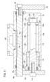
図1は、本実施の形態に係るワーク供給払出装置10が付設された歯車加工装置12の要部概略斜視図である。先ず、歯車加工装置12の主要な構成要素につき説明する。この歯車加工装置12は、テーブル14と、回転台16と、砥石18とを備える。回転台16は、テーブル14に対して回転可能に設けられており、円環形状をなすはすば歯車20がワークとして支持される。 FIG. 1 is a schematic perspective view of a main part of a gear processing device 12 to which a workpiece supplying and discharging device 10 according to the present embodiment is attached. First, the main components of the gear processing device 12 will be explained. This gear processing device 12 includes a table 14, a rotating table 16, and a grindstone 18. The rotary table 16 is rotatably provided with respect to the table 14, and supports a helical gear 20 having an annular shape as a workpiece.

砥石18は、回転台16に支持されたはすば歯車20の傾斜歯(はす歯)に対して研削を行うための研削具であり、矢印B方向に向かって回転可能となるように回転支持軸22に支持されている。また、砥石18は、矢印Y方向に沿ってシフトすることが可能であり、さらに、昇降盤24と一体的に矢印X方向に沿って前進又は後退すること、及び、矢印Z方向に沿って上昇又は下降することが可能である。このような歯車加工装置12は公知であることから、その他の構成要素に関する詳細な説明及び図示は省略する。 The grindstone 18 is a grinding tool for grinding the inclined teeth of the helical gear 20 supported on the rotary table 16, and rotates so that it can rotate in the direction of arrow B. It is supported by a support shaft 22. Further, the grindstone 18 can be shifted along the direction of the arrow Y, and furthermore, can be moved forward or backward along the direction of the arrow X integrally with the elevator plate 24, and can be raised along the direction of the arrow Z. Or it is possible to descend. Since such a gear processing device 12 is well known, detailed explanations and illustrations of other components will be omitted.

次に、本実施の形態に係るワーク供給払出装置10につき説明する。ワーク供給払出装置10は、歯車加工装置12とテーブル14を共有する。テーブル14の上面において、回転台16の近傍には中空台座26が突出形成される。すなわち、中空台座26はテーブル14の一部位である。ワーク供給払出装置10は、この中空台座26に設けられる。 Next, the workpiece supplying and discharging device 10 according to the present embodiment will be explained. The work supply and payout device 10 shares a table 14 with a gear processing device 12. A hollow pedestal 26 is formed protruding from the upper surface of the table 14 near the rotary table 16. That is, the hollow pedestal 26 is a part of the table 14. The work supply and payout device 10 is provided on this hollow pedestal 26.

ワーク供給払出装置10は、旋回部30と固定部32を備える。この中の旋回部30は、図2に示す旋回用モータ34(旋回用アクチュエータ)の作用下に、中空台座26上で旋回することが可能である。具体的には、前記旋回用モータ34はテーブル14に支持されるとともに、該旋回用モータ34を構成する回転軸36の先端が、中空台座26の内部に進入する。この回転軸36には、駆動ギヤ38が外嵌される。一方の旋回部30は、図2及び図3に示す内歯部材としての従動ギヤ40を含む。円環形状をなす従動ギヤ40の歯部は、その内周壁に内歯として刻設されている。勿論、駆動ギヤ38と従動ギヤ40の歯部同士は噛合しており、従って、回転軸36が回転すると、これに追従して、従動ギヤ40を含む旋回部30が旋回する。 The work supply and payout device 10 includes a rotating section 30 and a fixed section 32. The rotating part 30 in this can be rotated on the hollow pedestal 26 under the action of a rotating motor 34 (swing actuator) shown in FIG. Specifically, the turning motor 34 is supported by the table 14, and the tip of the rotating shaft 36 that constitutes the turning motor 34 enters the inside of the hollow pedestal 26. A drive gear 38 is fitted onto the rotating shaft 36 . One of the rotating parts 30 includes a driven gear 40 as an internal gear member shown in FIGS. 2 and 3. The teeth of the annular driven gear 40 are carved as internal teeth on the inner peripheral wall thereof. Of course, the teeth of the drive gear 38 and the driven gear 40 mesh with each other, so that when the rotating shaft 36 rotates, the rotating section 30 including the driven gear 40 rotates following the rotation of the rotating shaft 36.

旋回部30は、従動ギヤ40の上方に重畳された円環状プレート42をさらに含む。この円環状プレート42には、4本の案内用バー44a~44dが案内部材として立設される。案内用バー44a、44bは互いに近接し、同様に、案内用バー44c、44dも互いに近接して組をなしている。また、案内用バー44aと案内用バー44c、案内用バー44bと案内用バー44dは、互いに略180°で離間している。以下、離間角度を「位相差」と表記することもある。例えば、2個の部材の離間角度が180°である場合、該2個の部材の位相差は180°である。 The rotating portion 30 further includes an annular plate 42 superimposed above the driven gear 40 . Four guide bars 44a to 44d are erected on this annular plate 42 as guide members. The guide bars 44a and 44b are close to each other, and similarly the guide bars 44c and 44d are also close to each other and form a set. Further, the guide bar 44a and the guide bar 44c, and the guide bar 44b and the guide bar 44d are spaced apart from each other by approximately 180°. Hereinafter, the separation angle may also be referred to as "phase difference." For example, when the separation angle between two members is 180°, the phase difference between the two members is 180°.

中空台座26の内部には、該中空台座26の上面に支持されたスペーサ46が配設される。略柱状をなす固定部32の下端面は、スペーサ46の上端面に連結されている。固定部32は単一個の部材からなり、旋回部30が旋回した場合であってもこれに追従して旋回することはない。 A spacer 46 supported on the upper surface of the hollow pedestal 26 is disposed inside the hollow pedestal 26 . The lower end surface of the substantially columnar fixing portion 32 is connected to the upper end surface of the spacer 46 . The fixed part 32 is made of a single member, and even when the rotating part 30 turns, it does not turn to follow the turning part 30.

固定部32の下端の近傍には、第1固定レール50a、第2固定レール50bが位置決め固定される。第1固定レール50aと第2固定レール50bはいずれも、半円に満たない円弧形状をなす。このため、第1固定レール50aと第2固定レール50bの間には、第1離間箇所52a、第2離間箇所52bが形成される。第1離間箇所52aは、回転台16との位相差が略180°となる位置に形成され、一方、第2離間箇所52bは回転台16に対向する位置に形成される。 Near the lower end of the fixing portion 32, a first fixing rail 50a and a second fixing rail 50b are positioned and fixed. Both the first fixed rail 50a and the second fixed rail 50b have an arcuate shape that is less than a semicircle. For this reason, a first separated portion 52a and a second separated portion 52b are formed between the first fixed rail 50a and the second fixed rail 50b. The first separated portion 52a is formed at a position where the phase difference with the rotary table 16 is approximately 180°, while the second separated portion 52b is formed at a position facing the rotary table 16.

固定部32の、回転台16との位相差が略180°となる部位と、該部位に対して位相差が略180°であり回転台16に対向する部位には、湾曲した側周壁の一部が切り欠かれるようにして平坦面が形成されている。回転台16との位相差が略180°となる部位の平坦面には、第1進退用シリンダ54が設けられる。第1進退用シリンダ54を構成する第1進退用ロッド56の先端は、第1離間箇所52aに臨む。同様に、回転台16に対向する部位の平坦面には第2進退用シリンダ58が設けられ、この第2進退用シリンダ58を構成する第2進退用ロッド60の先端は、第2離間箇所52bに臨む。 A portion of the fixed portion 32 having a phase difference of approximately 180° with respect to the rotary table 16 and a portion having a phase difference of approximately 180° with respect to the portion and facing the rotary table 16 are provided with a portion of a curved side peripheral wall. A flat surface is formed by cutting out a portion. A first advancing/retracting cylinder 54 is provided on a flat surface at a portion where the phase difference with the rotary table 16 is approximately 180°. The tip of the first advancing/retracting rod 56 constituting the first advancing/retracting cylinder 54 faces the first separated portion 52a. Similarly, a second advancing/retracting cylinder 58 is provided on the flat surface of the portion facing the rotary table 16, and the tip of the second advancing/retracting rod 60 constituting the second advancing/retracting cylinder 58 is connected to a second spaced apart point 52b. I'm going to meet you.

図1に示すように、第1進退用ロッド56、第2進退用ロッド60の下端には、後述するカムフォロワ144に干渉しない部位に、略円弧形状の第1可動レール62a、第2可動レール62bがそれぞれ連結される。第1進退用ロッド56及び第2進退用ロッド60が下方に向かって伸張する(下降する)と、第1可動レール62aが第1離間箇所52aから退避するとともに、第2可動レール62bが第2離間箇所52bから退避する。 As shown in FIG. 1, at the lower ends of the first advancing/retracting rod 56 and the second advancing/retracting rod 60, a substantially arc-shaped first movable rail 62a and a second movable rail 62b are provided in a portion that does not interfere with a cam follower 144, which will be described later. are connected to each other. When the first advancing/retracting rod 56 and the second advancing/retracting rod 60 extend (descend) downward, the first movable rail 62a retreats from the first separated portion 52a, and the second movable rail 62b moves to the second Evacuate from the separation location 52b.

一方、第1進退用ロッド56及び第2進退用ロッド60が上方に向かって収縮する(上降する)と、第1可動レール62a、第2可動レール62bが第1離間箇所52a、第2離間箇所52bに進入する。すなわち、第1可動レール62a、第1固定レール50a、第2可動レール62b及び第2固定レール50bが円環状に連なる。このように、第1進退用シリンダ54及び第2進退用シリンダ58は、第1可動レール62a、第2可動レール62bを第1離間箇所52a、第2離間箇所52bに対して進入又は退避させる進退用アクチュエータである。 On the other hand, when the first advancing/retracting rod 56 and the second advancing/retracting rod 60 contract upward (move up and down), the first movable rail 62a and the second movable rail 62b are moved to the first separated part 52a and the second separated part 52a. Enter point 52b. That is, the first movable rail 62a, the first fixed rail 50a, the second movable rail 62b, and the second fixed rail 50b are connected in an annular shape. In this way, the first advancing/retracting cylinder 54 and the second advancing/retracting cylinder 58 move the first movable rail 62a and the second movable rail 62b into or out of the first separation point 52a and the second separation point 52b. It is an actuator for

ワーク供給払出装置10は、さらに、第1把持部64a、第2把持部64bを備える。これら第1把持部64a及び第2把持部64bは、はすば歯車20を第1把持爪66a、第2把持爪66b(いずれも把持部材)ではすば歯車20を把持するワーク把持部に相当する。図1では、第1把持部64aが図示しない供給台又は払出台に臨み、且つ第2把持部64bが回転台16に臨んでいる場合を示している。次に、これら第1把持部64a、第2把持部64bにつき説明する。 The work supply and payout device 10 further includes a first grip part 64a and a second grip part 64b. The first gripping part 64a and the second gripping part 64b correspond to a workpiece gripping part that grips the helical gear 20 with a first gripping claw 66a and a second gripping claw 66b (both are gripping members). do. FIG. 1 shows a case where the first gripping part 64a faces a supply table or a dispensing table (not shown), and the second gripping part 64b faces the rotating table 16. Next, the first gripping part 64a and the second gripping part 64b will be explained.

図4は、第1把持部64aの概略全体斜視図である。第1把持部64aは、ケーシング70と、該ケーシング70に対して接近又は離間するように変位する第1可動板72a、第2可動板72bと、ケーシング70に連結された第1ブッシュ保持板74a、第2ブッシュ保持板74bとを有する。第1把持爪66aは第1可動板72aに連結され、且つ第2把持爪66bは第2可動板72bに連結されている。以下、ケーシング70において、第1可動板72a及び第2可動板72bが設けられた側の端面を側面、第1把持爪66a、第2把持爪66bが延在する側を正面、第1ブッシュ保持板74a及び第2ブッシュ保持板74bが設けられた側を背面と指称する。また、第1可動板72aから第2可動板72bに向かう方向(又はその逆方向)を長手方向と表記することもある。 FIG. 4 is a schematic overall perspective view of the first grip part 64a. The first gripping portion 64a includes a casing 70, a first movable plate 72a that moves toward or away from the casing 70, a second movable plate 72b, and a first bush holding plate 74a that is connected to the casing 70. , and a second bush holding plate 74b. The first gripping claw 66a is connected to the first movable plate 72a, and the second gripping claw 66b is connected to the second movable plate 72b. Hereinafter, in the casing 70, the end surface on the side where the first movable plate 72a and the second movable plate 72b are provided is the side surface, the side where the first gripping claw 66a and the second gripping claw 66b extend is the front surface, and the first bush holding The side where the plate 74a and the second bush holding plate 74b are provided is referred to as the back side. Further, the direction from the first movable plate 72a to the second movable plate 72b (or the opposite direction) may be referred to as a longitudinal direction.

図5は第1把持部64aの概略正面図であり、図6は図5中のVI-VI線矢視断面図である。図6から諒解されるように、ケーシング70内には、長手方向に沿って延在する第1ラック収納孔76a、第2ラック収納孔76b、第1スプリング収納孔78a、第2スプリング収納孔78bが形成される。第1ラック収納孔76aと第2ラック収納孔76bは背面側で上下に並列し、第1スプリング収納孔78aと第2スプリング収納孔78bは正面側で上下に並列している。また、第1スプリング収納孔78a及び第2スプリング収納孔78bの内径は、第1ラック収納孔76a及び第2ラック収納孔76bに比して大である。 5 is a schematic front view of the first gripping portion 64a, and FIG. 6 is a sectional view taken along the line VI-VI in FIG. As understood from FIG. 6, inside the casing 70, there are a first rack storage hole 76a, a second rack storage hole 76b, a first spring storage hole 78a, and a second spring storage hole 78b that extend along the longitudinal direction. is formed. The first rack storage hole 76a and the second rack storage hole 76b are arranged vertically in parallel on the back side, and the first spring storage hole 78a and the second spring storage hole 78b are arranged vertically in parallel on the front side. Further, the inner diameters of the first spring storage hole 78a and the second spring storage hole 78b are larger than those of the first rack storage hole 76a and the second rack storage hole 76b.

第1ラック収納孔76a及び第2ラック収納孔76bは双方とも、両側面で開口している。また、ケーシング70には、背面から正面に向かって陥没するようにピニオン収納孔80が形成される。ピニオン収納孔80は、第1ラック収納孔76a及び第2ラック収納孔76bの長手方向略中間で、これら第1ラック収納孔76a及び第2ラック収納孔76bに個別に連なる。 Both the first rack storage hole 76a and the second rack storage hole 76b are open on both sides. Further, a pinion storage hole 80 is formed in the casing 70 so as to be recessed from the back side toward the front side. The pinion storage hole 80 is approximately midway in the longitudinal direction of the first rack storage hole 76a and the second rack storage hole 76b, and is connected to the first rack storage hole 76a and the second rack storage hole 76b individually.

第1ラック収納孔76a、第2ラック収納孔76bには、第1ラックギヤ82a、第2ラックギヤ82b(いずれも第1ギヤ)がそれぞれ収納される。図5に示すように、第1ラックギヤ82a、第2ラックギヤ82bはケーシング70に比して長尺であり、このため、各々の長手方向両端がケーシング70の両側面から露呈する。図5中のVII-VII線矢視断面図である図7に示すように、第1ラックギヤ82aの一端は、連結ボルト84を介して第2可動板72bに連結される。その一方で、第1ラックギヤ82aの他端は、第1可動板72aに形成された挿入孔86aに対して進入又は離間する。また、図5中のVIII-VIII線矢視断面図である図8に示すように、第2ラックギヤ82bの一端も同様に連結ボルト84を介して第1可動板72aに連結され、その他端は、第可動板72に形成された挿入孔86bに対して進入又は離間する。第1ラックギヤ82aないし第2ラックギヤ82bの側周壁と、挿入孔86a、86bの内周壁との間には遊びが形成される。
A first rack gear 82a and a second rack gear 82b (both are first gears) are housed in the first rack housing hole 76a and the second rack housing hole 76b, respectively. As shown in FIG. 5, the first rack gear 82a and the second rack gear 82b are longer than the casing 70, so that both longitudinal ends of each are exposed from both sides of the casing 70. As shown in FIG. 7, which is a sectional view taken along the line VII-VII in FIG. 5, one end of the first rack gear 82a is connected to the second movable plate 72b via a connecting bolt 84. On the other hand, the other end of the first rack gear 82a enters or separates from the insertion hole 86a formed in the first movable plate 72a. Furthermore, as shown in FIG. 8, which is a cross-sectional view taken along the line VIII-VIII in FIG. , enters or leaves the insertion hole 86b formed in the second movable plate 72b . Play is formed between the side peripheral walls of the first rack gear 82a to the second rack gear 82b and the inner peripheral walls of the insertion holes 86a and 86b.

図5~図7に示すように、第1ラックギヤ82aの歯部は第2ラックギヤ82bに臨む側に形成され、ピニオン収納孔80内に露呈する。一方、第2ラックギヤ82bの歯部は第1ラックギヤ82aに臨む側に形成され、上記と同様にピニオン収納孔80内に露呈する。 As shown in FIGS. 5 to 7, the teeth of the first rack gear 82a are formed on the side facing the second rack gear 82b and are exposed in the pinion storage hole 80. On the other hand, the teeth of the second rack gear 82b are formed on the side facing the first rack gear 82a, and are exposed in the pinion storage hole 80 in the same manner as described above.

ピニオン収納孔80には、ピニオンギヤ88(第2ギヤ)が収納される。該ピニオンギヤ88の歯部は、第1ラックギヤ82a、第2ラックギヤ82bの各歯部に噛合している。換言すれば、ピニオンギヤ88は、第1ラックギヤ82a、第2ラックギヤ82bに同時に噛合する。ピニオンギヤ88の、第1ラックギヤ82aに対する噛合箇所と第2ラックギヤ82bに対する噛合箇所との位相差は180°である。 A pinion gear 88 (second gear) is housed in the pinion housing hole 80 . The teeth of the pinion gear 88 mesh with the teeth of the first rack gear 82a and the second rack gear 82b. In other words, the pinion gear 88 meshes with the first rack gear 82a and the second rack gear 82b at the same time. The phase difference between the meshing location of the pinion gear 88 with the first rack gear 82a and the meshing location with the second rack gear 82b is 180°.

図6に示すように、ピニオンギヤ88には、被押圧部材である軸付回転板90が設けられる。具体的には、ピニオンギヤ88に形成された貫通孔91に対し、軸付回転板90の大径軸部92が通される。この軸付回転板90は、前記大径軸部92の他、円板部94と、該円板部94から大径軸部92と逆方向に向かって突出する小径軸部96とを有する。大径軸部92がベアリング98aを介してケーシング70に支持され、且つ小径軸部96がベアリング98bを介して閉塞カバー100に支持されることにより、軸付回転板90及びピニオンギヤ88が安定して回転可能となる。 As shown in FIG. 6, the pinion gear 88 is provided with a rotary plate 90 with a shaft, which is a pressed member. Specifically, the large-diameter shaft portion 92 of the shafted rotary plate 90 is passed through a through hole 91 formed in the pinion gear 88 . In addition to the large-diameter shaft portion 92, this shafted rotary plate 90 includes a disk portion 94 and a small-diameter shaft portion 96 that protrudes from the disk portion 94 in a direction opposite to the large-diameter shaft portion 92. The large-diameter shaft portion 92 is supported by the casing 70 via the bearing 98a, and the small-diameter shaft portion 96 is supported by the closing cover 100 via the bearing 98b, so that the shafted rotating plate 90 and the pinion gear 88 are stabilized. It becomes possible to rotate.

円板部94はピニオンギヤ88よりも大径であり、ピニオン収納孔80から露呈する。円板部94の、小径軸部96が設けられた面には、図9に示すように、係合ピン部102が小径軸部96と平行に突出する。この係合ピン部102は、ギヤ付勢部材としてのピニオン駆動ピン104に形成された長穴形状の挿通孔106に係合される。第1可動レール62aが第1離間箇所52aに進入し、その高さ位置が、第1固定レール50a及び第2固定レール50bの高さ位置と揃っているとき、ピニオン駆動ピン104の下端は、ケーシング70の下端から突出するように露呈する(図5参照)。後述するように、第1把持部64aないし第2把持部64bが下降したとき、ピニオン駆動ピン104は、旋回部30又は円環状プレート42から押圧を受け、ケーシング70に対して相対的に上昇する。この際、ピニオンギヤ88が回転する。 The disc portion 94 has a larger diameter than the pinion gear 88 and is exposed from the pinion storage hole 80. As shown in FIG. 9, on the surface of the disk portion 94 on which the small diameter shaft portion 96 is provided, an engagement pin portion 102 projects in parallel to the small diameter shaft portion 96. This engagement pin portion 102 is engaged with an elongated insertion hole 106 formed in a pinion drive pin 104 as a gear biasing member. When the first movable rail 62a enters the first separated portion 52a and its height is aligned with the height of the first fixed rail 50a and the second fixed rail 50b, the lower end of the pinion drive pin 104 is It is exposed so as to protrude from the lower end of the casing 70 (see FIG. 5). As will be described later, when the first gripping portion 64a to the second gripping portion 64b descend, the pinion drive pin 104 receives pressure from the rotating portion 30 or the annular plate 42 and rises relative to the casing 70. . At this time, pinion gear 88 rotates.

以上のピニオン駆動ピン104、ピニオンギヤ88、第1ラックギヤ82a、第2ラックギヤ82bにより、第1把持部64a及び第2把持部64bが昇降動作する運動が、第1把持爪66a及び第2把持爪66bが開閉動作する運動に変換される。すなわち、ピニオン駆動ピン104、ピニオンギヤ88、第1ラックギヤ82a、第2ラックギヤ82bは、運動方向を変換するカム部を構成する。 The above-mentioned pinion drive pin 104, pinion gear 88, first rack gear 82a, and second rack gear 82b move the first gripping part 64a and the second gripping part 64b up and down by the first gripping claw 66a and the second gripping claw 66b. is converted into an opening/closing motion. That is, the pinion drive pin 104, pinion gear 88, first rack gear 82a, and second rack gear 82b constitute a cam portion that changes the direction of movement.

図7に示すように、第1スプリング収納孔78aは第1可動板72a側の側面で開口し、第2可動板72b側の側面では閉塞されている。一方、第2スプリング収納孔78bは、図8に示すように、上記とは逆に第2可動板72b側の側面で開口し、第1可動板72a側の側面で閉塞されている。 As shown in FIG. 7, the first spring storage hole 78a is open on the side surface on the first movable plate 72a side, and is closed on the side surface on the second movable plate 72b side. On the other hand, as shown in FIG. 8, the second spring storage hole 78b is open on the side surface on the second movable plate 72b side, contrary to the above, and is closed on the side surface on the first movable plate 72a side.

第1スプリング収納孔78aには第1変位ロッド110aが収納される(図7参照)。第1変位ロッド110aは、取付ボルト112を介して第1可動板72aに取り付けられている。このため、第1変位ロッド110aは、第1可動板72aが変位することに伴って第1スプリング収納孔78a内を変位する。また、第1変位ロッド110aは、第1可動板72aから第2可動板72bに向かって大径部114、中径部116、小径部118をこの順序で有する。小径部118と中径部116の境界には、略C形状をなすクリップ型の第1ストッパ120が設けられる。この第1ストッパ120は、小径部118に螺合されたナット122によって押止されている。 The first displacement rod 110a is housed in the first spring housing hole 78a (see FIG. 7). The first displacement rod 110a is attached to the first movable plate 72a via attachment bolts 112. Therefore, the first displacement rod 110a is displaced within the first spring storage hole 78a as the first movable plate 72a is displaced. Further, the first displacement rod 110a has a large diameter portion 114, a medium diameter portion 116, and a small diameter portion 118 in this order from the first movable plate 72a to the second movable plate 72b. A clip-type first stopper 120 having a substantially C shape is provided at the boundary between the small diameter portion 118 and the medium diameter portion 116 . This first stopper 120 is held down by a nut 122 screwed onto the small diameter portion 118.

第1スプリング収納孔78aの内径は第1可動板72a側で大きく設定されており、第2可動板72b側に向かうにつれて段階的に小さくなる。このため、第1スプリング収納孔78aは大径孔124、中径孔126、小径孔128を含む。中径孔126と小径孔128の間には、両孔126、128の径差に基づいて環状段部130が形成される。また、大径孔124には、略円板形状をなす鍔型の第2ストッパ132が位置決め固定される。そして、第1ストッパ120と第2ストッパ132の間には、弾性部材としての第1リターンスプリング134aが介挿されている。すなわち、第1リターンスプリング134aの第1可動板72a側の端部は第2ストッパ132に着座し、且つ第2可動板72b側の端部は第1ストッパ120に着座する。 The inner diameter of the first spring storage hole 78a is set to be large on the first movable plate 72a side, and gradually decreases toward the second movable plate 72b side. Therefore, the first spring storage hole 78a includes a large diameter hole 124, a medium diameter hole 126, and a small diameter hole 128. An annular step portion 130 is formed between the medium diameter hole 126 and the small diameter hole 128 based on the diameter difference between the two holes 126 and 128. Further, a collar-shaped second stopper 132 having a substantially disk shape is positioned and fixed in the large diameter hole 124 . A first return spring 134a serving as an elastic member is inserted between the first stopper 120 and the second stopper 132. That is, the end of the first return spring 134a on the first movable plate 72a side is seated on the second stopper 132, and the end on the second movable plate 72b side is seated on the first stopper 120.

一方、第2スプリング収納孔78bには第2変位ロッド110bが収納される(図8参照)。第2変位ロッド110bの、ケーシング70から突出した一端は、取付ボルト112を介して第2可動板72bに取り付けられる。このため、第2変位ロッド110bは、第2可動板72bが変位することに伴って第2スプリング収納孔78b内を変位する。このことから諒解されるように、第2スプリング収納孔78b内は、第1スプリング収納孔78a内と左右が反転している程度であり、構成要素は同一である。従って、詳細な説明及び図示は省略する。なお、以下では、第2スプリング収納孔78b内のバネを第2リターンスプリングと指称し参照符号を134bとすることを除き、第1スプリング収納孔78a内の構成要素と対応する構成要素には同一の参照符号を付す。第2リターンスプリング134bが弾性部材であることは勿論である。 On the other hand, the second displacement rod 110b is housed in the second spring housing hole 78b (see FIG. 8). One end of the second displacement rod 110b protruding from the casing 70 is attached to the second movable plate 72b via a mounting bolt 112. Therefore, the second displacement rod 110b is displaced within the second spring storage hole 78b as the second movable plate 72b is displaced. As can be understood from this, the inside of the second spring storage hole 78b is just a left-right inversion of the inside of the first spring storage hole 78a, and the components are the same. Therefore, detailed explanation and illustration will be omitted. Note that, in the following, components corresponding to those in the first spring storage hole 78a are the same, except that the spring in the second spring storage hole 78b is referred to as a second return spring and the reference numeral is 134b. Attach the reference sign. It goes without saying that the second return spring 134b is an elastic member.

後述する図11及び図12では、第1可動板72a(及び第1把持爪66a)と第2可動板72b(及び第2把持爪66b)とが互いに接近した閉状態を示している。この場合、第2変位ロッド110b及び第ストッパ120が第1可動板72a側に相対的に接近し、第2リターンスプリング134bが伸張状態となる。この際、第1変位ロッド110a及び第1ストッパ120が第2可動板72b側に相対的に接近するので、第1リターンスプリング134aも伸張状態となっている。
11 and 12, which will be described later, show a closed state in which the first movable plate 72a (and first gripping claw 66a) and the second movable plate 72b (and second gripping claw 66b) are close to each other. In this case, the second displacement rod 110b and the first stopper 120 relatively approach the first movable plate 72a, and the second return spring 134b is in an expanded state. At this time, since the first displacement rod 110a and the first stopper 120 relatively approach the second movable plate 72b side, the first return spring 134a is also in an expanded state.

これに対し、図7及び図8では、第1可動板72a(及び第1把持爪66a)と第2可動板72b(及び第2把持爪66b)とが互いに離間した開状態を示している。この場合、第1変位ロッド110a及び第1ストッパ120が第可動板72に対して相対的に離間することから、第1リターンスプリング134aは圧縮状態にある。この際、第2変位ロッド110b及び第ストッパ120は第可動板72に対して相対的に離間している。すなわち、第2リターンスプリング134bもまた圧縮状態となっている。
On the other hand, FIGS. 7 and 8 show an open state in which the first movable plate 72a (and first gripping claw 66a) and the second movable plate 72b (and second gripping claw 66b) are spaced apart from each other. In this case, since the first displacement rod 110a and the first stopper 120 are spaced apart relative to the second movable plate 72b , the first return spring 134a is in a compressed state. At this time, the second displacement rod 110b and the first stopper 120 are spaced apart from the first movable plate 72a . That is, the second return spring 134b is also in a compressed state.

図4に示すように、第1ブッシュ保持板74a、第2ブッシュ保持板74bは幅狭の連結部位136と、連結部位136から拡開した若干幅広のブッシュ支持部138とをそれぞれ有する。ブッシュ支持部138には、公知の第1スライドブッシュ140a、第2スライドブッシュ140bが位置決め固定される。第1スライドブッシュ140aは案内用バー44aに摺動可能に通され、且つ第2スライドブッシュ140bは案内用バー44bに摺動可能に通されている。 As shown in FIG. 4, the first bush holding plate 74a and the second bush holding plate 74b each have a narrow connection portion 136 and a slightly wide bush support portion 138 that expands from the connection portion 136. A known first slide bush 140a and a second slide bush 140b are positioned and fixed to the bush support portion 138. The first slide bush 140a is slidably passed through the guide bar 44a, and the second slide bush 140b is slidably passed through the guide bar 44b.

さらに、ケーシング70の上面には支持盤142が設けられる。該支持盤142には、滑動部材としての2個のカムフォロワ144が回転可能に支持される。2個のカムフォロワ144は、第1可動レール62a、第2可動レール62b、第1固定レール50a及び第2固定レール50bの曲率半径に対応する曲率半径となるように、ケーシング70の正面から背面に向かう奥行き方向に対して若干傾斜している。第1可動レール62a、第2可動レール62b、第1固定レール50a及び第2固定レール50bは、ケーシング70の上面と、カムフォロワ144との間に通される。すなわち、カムフォロワ144は、第1可動レール62a、第2可動レール62b、第1固定レール50a又は第2固定レール50bに沿って滑動する。 Further, a support plate 142 is provided on the upper surface of the casing 70. Two cam followers 144 as sliding members are rotatably supported on the support plate 142. The two cam followers 144 extend from the front to the back of the casing 70 so that the radius of curvature corresponds to the radius of curvature of the first movable rail 62a, the second movable rail 62b, the first fixed rail 50a, and the second fixed rail 50b. It is slightly inclined in the depth direction. The first movable rail 62a, the second movable rail 62b, the first fixed rail 50a, and the second fixed rail 50b are passed between the upper surface of the casing 70 and the cam follower 144. That is, the cam follower 144 slides along the first movable rail 62a, the second movable rail 62b, the first fixed rail 50a, or the second fixed rail 50b.

残余の第2把持部64bは、第1把持部64aと同様に構成される。従って、第1把持部64aの構成要素と同一の構成要素には同一の参照符号を付し、その詳細な説明を省略する。なお、第2把持部64bの第1スライドブッシュ140aは案内用バー44cに摺動可能に通されており、第2スライドブッシュ140bは案内用バー44dに摺動可能に通されている。 The remaining second gripping portion 64b is configured similarly to the first gripping portion 64a. Therefore, the same reference numerals are given to the same components as those of the first gripping part 64a, and detailed explanation thereof will be omitted. Note that the first slide bush 140a of the second gripping portion 64b is slidably passed through the guide bar 44c, and the second slide bush 140b is slidably passed through the guide bar 44d.

本実施の形態に係るワーク供給払出装置10は、基本的には以上のように構成されるものであり、次にその作用効果につき、ワーク供給払出装置10の動作との関係で説明する。なお、説明の便宜上、回転台16に支持されたはすば歯車20に対して砥石18による歯部の研削を行い、その後、得られた製品歯車150を払い出すとともに新たなはすば歯車20を回転台16に供給する場合を例示する。また、以下の動作は、図示しない制御回路のシーケンス制御作用下に営まれる。 The workpiece supplying and dispensing device 10 according to the present embodiment is basically configured as described above, and its effects will be explained next in relation to the operation of the workpiece supplying and dispensing device 10. For convenience of explanation, the teeth of the helical gear 20 supported on the rotary table 16 are ground with the grindstone 18, and then the obtained product gear 150 is discharged and a new helical gear 20 is ground. An example of supplying the rotation table 16 to the turntable 16 will be described. Further, the following operations are carried out under the sequence control action of a control circuit (not shown).

このとき、第1把持部64aが図示しない前記供給台に臨み、且つ第2把持部64bが回転台16に臨む。また、第1把持部64a、第2把持部64bのいずれにおいても、第1把持爪66aと第2把持爪66bは、互いが接近した閉状態である。また、第1可動レール62a、第1固定レール50a、第2可動レール62b及び第2固定レール50bの高さ位置は一致しており、これら4個のレール50a、50b、62a、62bが円を描くように連なっている。さらに、第1把持部64aの2個のカムフォロワ144は第1可動レール62a上に位置し、且つ第2把持部64bの2個のカムフォロワ144は第2可動レール62b上に位置している。このため、第1把持部64aは第1可動レール62aに保持され、第2把持部64bは第2可動レール62bに保持されている。 At this time, the first gripping part 64a faces the supply table (not shown), and the second gripping part 64b faces the rotating table 16. Further, in both the first gripping part 64a and the second gripping part 64b, the first gripping claw 66a and the second gripping claw 66b are in a closed state in which they are close to each other. Further, the height positions of the first movable rail 62a, the first fixed rail 50a, the second movable rail 62b, and the second fixed rail 50b are the same, and these four rails 50a, 50b, 62a, and 62b form a circle. They are connected as if drawn. Furthermore, the two cam followers 144 of the first gripping part 64a are located on the first movable rail 62a, and the two cam followers 144 of the second gripping part 64b are located on the second movable rail 62b. Therefore, the first gripping part 64a is held by the first movable rail 62a, and the second gripping part 64b is held by the second movable rail 62b.

この状態で、第1進退用シリンダ54が付勢される。すなわち、第1進退用ロッド56が下降する。この下降に伴い、第1進退用ロッド56の先端に連結された第1可動レール62aが一体的に下降し、第1離間箇所52aから退避する。すなわち、図1(及び図2中の実線)に示すように、第1可動レール62aが第1固定レール50a及び第2固定レール50bよりも低位置となる。上記したように、この時点では第1把持部64aが第1可動レール62aに保持されているので、第1把持部64aも第1可動レール62aと一体的に下降し、下降前よりも低位置となる。なお、図2の実線は、最低位置となったときの第1把持部64aを示している。
In this state, the first advancing/retracting cylinder 54 is energized. That is, the first advancing/retracting rod 56 descends. Along with this lowering, the first movable rail 62a connected to the tip of the first advancing/retracting rod 56 lowers integrally and retreats from the first separation location 52a. That is, as shown in FIG. 1 (and the solid line in FIG. 2), the first movable rail 62a is at a lower position than the first fixed rail 50a and the second fixed rail 50b. As described above, at this point, the first gripping part 64a is held by the first movable rail 62a, so the first gripping part 64a also lowers integrally with the first movable rail 62a , and is lowered to a lower level than before the descent. position. Note that the solid line in FIG. 2 indicates the first grip portion 64a at the lowest position.

第1把持部64aが下降を開始してから最低位置となるまでの間、第1スライドブッシュ140a、第2スライドブッシュ140bは、案内用バー44a、44bにそれぞれ案内される。このため、第1把持部64aが位置ズレを起こすことが回避される。 The first slide bush 140a and the second slide bush 140b are guided by the guide bars 44a and 44b, respectively, from when the first grip part 64a starts descending until it reaches the lowest position. This prevents the first gripping portion 64a from being misaligned.

この下降に伴い、第1把持部64aのケーシング70の下端から露呈したピニオン駆動ピン104(図9参照)の下端が円環状プレート42に当接する。第1進退用ロッド56がさらに下降すると、ピニオン駆動ピン104に対して円環状プレート42が相対的に上昇するので、ピニオン駆動ピン104が該円環状プレート42から押圧を受ける。その結果、図10に示すように、ピニオン駆動ピン104の大部分がケーシング70の内部に押し込まれる。換言すれば、下降するケーシング70内をピニオン駆動ピン104が相対的に上昇し、ピニオンギヤ88に接近する。 With this lowering, the lower end of the pinion drive pin 104 (see FIG. 9) exposed from the lower end of the casing 70 of the first gripping part 64a comes into contact with the annular plate 42. When the first advancing/retracting rod 56 further descends, the annular plate 42 rises relative to the pinion drive pin 104, so the pinion drive pin 104 receives pressure from the annular plate 42. As a result, as shown in FIG. 10, most of the pinion drive pin 104 is pushed into the casing 70. In other words, the pinion drive pin 104 relatively rises inside the descending casing 70 and approaches the pinion gear 88.

ここで、ピニオン駆動ピン104に形成された挿通孔106には、軸付回転板90の円板部94に設けられた係合ピン部102が係合している。従って、ピニオン駆動ピン104がピニオンギヤ88に接近するように変位することに伴い、軸付回転板90がケーシング70の背面視で時計回り、正面視で反時計回りに回転する。ピニオンギヤ88の歯部が第1ラックギヤ82a、第2ラックギヤ82bの各歯部に噛合していることから、ピニオンギヤ88が上記のように回転することに追従し、第1ラックギヤ82aが第1可動板72aから離間するように変位し、且つ第2ラックギヤ82bが第2可動板72bから離間するように変位する。 Here, an engagement pin portion 102 provided on the disc portion 94 of the rotary plate 90 with a shaft is engaged with the insertion hole 106 formed in the pinion drive pin 104 . Therefore, as the pinion drive pin 104 moves closer to the pinion gear 88, the shafted rotary plate 90 rotates clockwise when viewed from the rear of the casing 70 and counterclockwise when viewed from the front. Since the teeth of the pinion gear 88 mesh with the teeth of the first rack gear 82a and the second rack gear 82b, the rotation of the pinion gear 88 as described above is followed, and the first rack gear 82a is connected to the first movable plate. 72a, and the second rack gear 82b is displaced away from the second movable plate 72b.

このため、第1ラックギヤ82aに保持された第2可動板72bと、第2ラックギヤ82bに保持された第1可動板72aとが互いに離間する。その結果として、図7及び図8に示すように、第1可動板72aに保持された第1把持爪66aと、第2可動板72bに保持された第2把持爪66bとが互いに離間し、開状態となる。この時点で、図1に示すように、第1把持爪66aと第2把持爪66bの間にはすば歯車20が位置する。すなわち、第1把持部64aが最低位置となったとき、第1把持爪66aと第2把持爪66bはワーク解放位置となる。 Therefore, the second movable plate 72b held by the first rack gear 82a and the first movable plate 72a held by the second rack gear 82b are separated from each other. As a result, as shown in FIGS. 7 and 8, the first gripping claw 66a held by the first movable plate 72a and the second gripping claw 66b held by the second movable plate 72b are separated from each other, It becomes open. At this point, as shown in FIG. 1, the helical gear 20 is positioned between the first gripping claw 66a and the second gripping claw 66b. That is, when the first gripping portion 64a is at the lowest position, the first gripping claw 66a and the second gripping claw 66b are at the work release position.

なお、第1可動板72aが第2可動板72bから離間するように変位する間、第1ラックギヤ82aの、第1可動板72a側に臨む端部は、第1可動板72aに形成された挿入孔86aから離脱する(図7参照)。同様に、第2可動板72bが第1可動板72aから離間するように変位する間、第2ラックギヤ82bの、第2可動板72b側に臨む端部は、第2可動板72bに形成された挿入孔86bから離脱する(図8参照)。 Note that while the first movable plate 72a is displaced away from the second movable plate 72b, the end portion of the first rack gear 82a facing the first movable plate 72a is inserted into the insertion hole formed on the first movable plate 72a. It separates from the hole 86a (see FIG. 7). Similarly, while the second movable plate 72b is displaced away from the first movable plate 72a, the end of the second rack gear 82b facing the second movable plate 72b is formed on the second movable plate 72b. It is removed from the insertion hole 86b (see FIG. 8).

さらに、以上のようにして第1把持爪66aと第2把持爪66bが開状態(ワーク解放位置)となることに伴い、第1変位ロッド110a及び第1ストッパ120が第2可動板72bから離間する方向に変位する(図7参照)とともに、第2変位ロッド110b及び第1ストッパ120が第1可動板72aから離間する方向に変位する(図8参照)。この変位により、環状段部130から離間した第1ストッパ120が、位置不変の第2ストッパ132に接近する。従って、第1ストッパ120と第2ストッパ132の間に介挿された第1リターンスプリング134a、第2リターンスプリング134bがそれぞれ圧縮される。 Further, as the first gripping claw 66a and the second gripping claw 66b are brought into the open state (work release position) as described above, the first displacement rod 110a and the first stopper 120 are separated from the second movable plate 72b. At the same time, the second displacement rod 110b and the first stopper 120 are displaced in the direction away from the first movable plate 72a (see FIG. 8). Due to this displacement, the first stopper 120 separated from the annular step 130 approaches the second stopper 132 whose position remains unchanged. Therefore, the first return spring 134a and the second return spring 134b inserted between the first stopper 120 and the second stopper 132 are compressed.

次に、第1進退用シリンダ54が付勢されて第1進退用ロッド56が上昇する。この上昇により第1可動レール62a及び第1把持部64aが一体的に上昇する。上昇の際にも第1スライドブッシュ140a、第2スライドブッシュ140bが案内用バー44a、44bにそれぞれ案内されるので、第1把持部64aが位置ズレを起こすことが回避される。 Next, the first advancing/retracting cylinder 54 is energized and the first advancing/retracting rod 56 is raised. Due to this rise, the first movable rail 62a and the first grip portion 64a rise integrally. Even during the ascent, the first slide bush 140a and the second slide bush 140b are guided by the guide bars 44a and 44b, respectively, so that the first grip part 64a is prevented from being displaced.

そして、このように第1把持部64aが上昇することにより、ピニオン駆動ピン104が円環状プレート42から受ける反力(ピニオン駆動ピン104に対する円環状プレート42の押圧力)が次第に小さくなる。最終的に、上記のようにして圧縮された第1リターンスプリング134a及び第2リターンスプリング134bの弾発付勢力が、円環状プレート42からの反力を上回るに至る。すなわち、図11及び図12に示すように、第1リターンスプリング134a及び第2リターンスプリング134bが伸張する。この伸張に伴って、第1変位ロッド110aに設けられた第1ストッパ120が第2可動板72b側に弾発付勢されるとともに、第2変位ロッド110bに設けられた第1ストッパ120が第1可動板72a側に弾発付勢される。
As the first gripping portion 64a rises in this manner, the reaction force that the pinion drive pin 104 receives from the annular plate 42 (the pressing force of the annular plate 42 against the pinion drive pin 104) gradually decreases. Eventually, the resilient urging force of the first return spring 134a and the second return spring 134b compressed as described above exceeds the reaction force from the annular plate 42 . That is, as shown in FIGS. 11 and 12, the first return spring 134a and the second return spring 134b are expanded. With this extension, the first stopper 120 provided on the first displacement rod 110a is resiliently biased toward the second movable plate 72b, and the first stopper 120 provided on the second displacement rod 110b is urged toward the second movable plate 72b. 1 movable plate 72a side.

従って、第1変位ロッド110a及び第1可動板72aが第2可動板72bに接近するように変位し、且つ第2変位ロッド110b及び第2可動板72bが第1可動板72aに接近するように変位する。これに追従し、第1可動板72aに保持された第1把持爪66aと、第2可動板72bに保持された第2把持爪66bとが互いに接近して閉状態となる。その結果、はすば歯車20が第1把持爪66aと第2把持爪66bに把持される。すなわち、第1把持部64aが上昇することに伴い、第1把持爪66aと第2把持爪66bがワーク把持位置に変化する。 Therefore, the first displacement rod 110a and the first movable plate 72a are displaced so as to approach the second movable plate 72b, and the second displacement rod 110b and the second movable plate 72b are displaced so as to approach the first movable plate 72a. Displace. Following this, the first gripping claw 66a held by the first movable plate 72a and the second gripping claw 66b held by the second movable plate 72b approach each other and enter the closed state. As a result, the helical gear 20 is gripped by the first gripping claw 66a and the second gripping claw 66b. That is, as the first gripping portion 64a rises, the first gripping claw 66a and the second gripping claw 66b change to the workpiece gripping position.

そして、第1把持爪66aと第2把持爪66bが互いに接近することにより、第1可動板72aを保持した第2ラックギヤ82bと、第2可動板72bを保持した第1ラックギヤ82aとが互いに接近するように変位する。このとき、第1ラックギヤ82a及び第2ラックギヤ82bの各歯部に噛合したピニオンギヤ88が、ケーシング70の背面視で反時計回り、正面視で時計回りに回転する。この回転により、ピニオン駆動ピン104が、上昇するケーシング70内で相対的に下降する。その結果、該ピニオン駆動ピン104の下端がケーシング70から徐々に突出し始める。なお、この間、第1ラックギヤ82aの、第1可動板72a側に臨む端部は、第1可動板72aに形成された挿入孔86aに進入する。同様に、第2ラックギヤ82bの、第2可動板72b側に臨む端部は、第2可動板72bに形成された挿入孔86bに進入する。 Then, as the first gripping claw 66a and the second gripping claw 66b approach each other, the second rack gear 82b holding the first movable plate 72a and the first rack gear 82a holding the second movable plate 72b approach each other. Displace as shown. At this time, the pinion gear 88 meshed with each tooth of the first rack gear 82a and the second rack gear 82b rotates counterclockwise when viewed from the rear of the casing 70 and clockwise when viewed from the front. This rotation causes the pinion drive pin 104 to move relatively downward within the rising casing 70. As a result, the lower end of the pinion drive pin 104 begins to gradually protrude from the casing 70. During this time, the end of the first rack gear 82a facing the first movable plate 72a enters the insertion hole 86a formed in the first movable plate 72a. Similarly, the end of the second rack gear 82b facing the second movable plate 72b enters an insertion hole 86b formed in the second movable plate 72b.

第1リターンスプリング134a及び第2リターンスプリング134bの伸張は、第1スプリング収納孔78a、第2スプリング収納孔78b内の環状段部130に第1ストッパ120が堰き止められることによって停止する。このときに第1把持部64aが図2に仮想線で示す位置に戻る。すなわち、第1可動レール62aが第1離間箇所52aに進入し、その高さ位置と、第1固定レール50a及び第2固定レール50bの高さ位置とが揃う。この際、第1把持爪66aと第2把持爪66bで把持されたはすば歯車20が供給台から十分に離間する。 The expansion of the first return spring 134a and the second return spring 134b is stopped by the first stopper 120 being dammed by the annular step portion 130 in the first spring storage hole 78a and the second spring storage hole 78b. At this time, the first grip portion 64a returns to the position shown by the imaginary line in FIG. That is, the first movable rail 62a enters the first separated portion 52a, and its height position is aligned with the height positions of the first fixed rail 50a and the second fixed rail 50b. At this time, the helical gear 20 held by the first gripping claw 66a and the second gripping claw 66b is sufficiently separated from the supply stage.

第2把持部64bにおいても同様の動作が営まれる。すなわち、第1進退用シリンダ54が付勢されることに同期して第2進退用シリンダ58が付勢され、第2進退用ロッド60が下降する。これにより第2可動レール62b及び第2把持部64bが一体的に下降し、第2離間箇所52bから退避して第1固定レール50a及び第2固定レール50bよりも低位置となる(図2中の実線参照)。 A similar operation is performed on the second gripping portion 64b as well. That is, in synchronization with the activation of the first advancing/retracting cylinder 54, the second advancing/retracting cylinder 58 is energized, and the second advancing/retracting rod 60 is lowered. As a result, the second movable rail 62b and the second gripping part 64b are lowered together, retreated from the second separated part 52b, and are at a lower position than the first fixed rail 50a and the second fixed rail 50b (in FIG. (see solid line).

そして、ピニオン駆動ピン104が下降するケーシング70内を相対的に上昇し、ピニオンギヤ88に接近する。その結果として開状態となった第1把持爪66aと第2把持爪66bの間に、製品歯車150が位置する。勿論、第1可動板72aと第2可動板72bの間に配設された第1リターンスプリング134a、第2リターンスプリング134bが圧縮される。 Then, the pinion drive pin 104 relatively rises inside the descending casing 70 and approaches the pinion gear 88. As a result, the product gear 150 is located between the first gripping claw 66a and the second gripping claw 66b, which are in the open state. Of course, the first return spring 134a and the second return spring 134b disposed between the first movable plate 72a and the second movable plate 72b are compressed.

その後、第2進退用シリンダ58が再付勢されて第2進退用ロッド60が上昇する。この上昇に伴い、第1可動板72a(及び第1把持爪66a)と第2可動板72b(及び第2把持爪66b)が互いに接近して第1把持爪66aと第2把持爪66bが閉状態となるので、製品歯車150が第2把持部64bにしっかりと把持される。また、第1リターンスプリング134a、第2リターンスプリング134bが次第に伸張し、最終的に元の長さに戻る。以上の下降及び上昇の間、第1スライドブッシュ140a、第2スライドブッシュ140bが案内用バー44c、44dに案内されることや、ピニオン駆動ピン104が第2把持部64bのケーシング70内を相対的に上昇及び下降することは勿論である。 Thereafter, the second advancing/retracting cylinder 58 is reenergized and the second advancing/retracting rod 60 is raised. As this rises, the first movable plate 72a (and first gripping claw 66a) and the second movable plate 72b (and second gripping claw 66b) approach each other, and the first gripping claw 66a and second gripping claw 66b close. In this state, the product gear 150 is firmly gripped by the second gripping portion 64b. Further, the first return spring 134a and the second return spring 134b gradually expand and eventually return to their original lengths. During the above-described descent and ascent, the first slide bush 140a and the second slide bush 140b are guided by the guide bars 44c and 44d, and the pinion drive pin 104 moves relatively inside the casing 70 of the second gripping portion 64b. Of course, it rises and falls as well.

第2把持部64bは、第2可動レール62bが第2離間箇所52bに進入し、その高さ位置と、第1固定レール50a及び第2固定レール50bの高さ位置とが揃うまで上昇する。この際、第1把持爪66aと第2把持爪66bで把持された製品歯車150が回転台16から十分に離間する。
The second gripping portion 64b rises until the second movable rail 62b enters the second separated portion 52b and its height is aligned with the height of the first fixed rail 50a and the second fixed rail 50b. At this time, the product gear 150 held by the first gripping claw 66a and the second gripping claw 66b is sufficiently separated from the rotating table 16.

次に、旋回用モータ34(図2及び図3参照)が付勢される。これにより回転軸36及び駆動ギヤ38が一体的に回転すると、その歯部が駆動ギヤ38の歯部に噛合した従動ギヤ40が約180°回転(旋回)する。この回転に追従し、該従動ギヤ40や円環状プレート42を含む旋回部30が約180°旋回する。ここで、案内用バー44a~44dはいずれも円環状プレート42に立設されているので、従動ギヤ40とともに旋回する。旋回方向は、例えば、時計回り方向である。この旋回の間、前記供給台が前記払出台に自動的に交代する。 Next, the turning motor 34 (see FIGS. 2 and 3) is energized. As a result, when the rotating shaft 36 and the driving gear 38 rotate together, the driven gear 40 whose teeth mesh with the teeth of the driving gear 38 rotates (swivels) about 180 degrees. Following this rotation, the rotating portion 30 including the driven gear 40 and the annular plate 42 rotates approximately 180 degrees. Here, since the guide bars 44a to 44d are all erected on the annular plate 42, they rotate together with the driven gear 40. The turning direction is, for example, clockwise. During this rotation, the supply table is automatically replaced by the dispensing table.

案内用バー44a、44bには、第1把持部64aの第1スライドブッシュ140a、第2スライドブッシュ140bがそれぞれ通されている。従って、第1把持部64aが案内用バー44a、44bに同伴されて約180°旋回する。この際、第1把持部64aのカムフォロワ144は、第1可動レール62a上を滑動して第1固定レール50aに乗り移り、さらに、第1固定レール50a上を滑動して第2可動レール62bに乗り移る。約180°の旋回により、第1把持部64aと、該第1把持部64aの第1把持爪66aと第2把持爪66bに把持されたはすば歯車20とが、回転台16に臨む。すなわち、旋回に伴ってはすば歯車20が回転台16側に搬送される。 A first slide bush 140a and a second slide bush 140b of the first grip portion 64a are passed through the guide bars 44a and 44b, respectively. Therefore, the first gripping part 64a rotates about 180 degrees accompanied by the guide bars 44a and 44b. At this time, the cam follower 144 of the first gripping part 64a slides on the first movable rail 62a and transfers to the first fixed rail 50a, and further slides on the first fixed rail 50a and transfers to the second movable rail 62b. . By turning about 180 degrees, the first gripping part 64a and the helical gear 20 gripped by the first gripping claw 66a and the second gripping claw 66b of the first gripping part 64a face the rotating table 16. That is, the helical gear 20 is conveyed to the rotary table 16 side as it turns.

また、案内用バー44c、44dには、第2把持部64bの第1スライドブッシュ140a、第2スライドブッシュ140bがそれぞれ通されている。従って、第1把持部64aが案内用バー44a、44bに同伴されて旋回すると同時に、第2把持部64bが案内用バー44c、44dに同伴されて旋回する。この際、第2把持部64bのカムフォロワ144は、第2可動レール62b上を滑動して第2固定レール50bに乗り移り、さらに、第2固定レール50b上を滑動して第1可動レール62aに乗り移る。約180°の旋回により、第2把持部64bと、該第2把持部64bの第1把持爪66aと第2把持爪66bに把持された製品歯車150とが、払出台に臨む。すなわち、旋回に伴って製品歯車150が回転台16から搬送される。 Further, the first slide bush 140a and the second slide bush 140b of the second gripping portion 64b are passed through the guide bars 44c and 44d, respectively. Therefore, the first gripping part 64a turns along with the guide bars 44a and 44b, and at the same time, the second gripping part 64b turns around along with the guide bars 44c and 44d. At this time, the cam follower 144 of the second gripping part 64b slides on the second movable rail 62b and transfers to the second fixed rail 50b, and further slides on the second fixed rail 50b and transfers to the first movable rail 62a. . By turning about 180 degrees, the second gripping part 64b and the product gear 150 gripped by the first gripping claw 66a and the second gripping claw 66b of the second gripping part 64b face the dispensing table. That is, the product gear 150 is conveyed from the rotary table 16 as it rotates.

以降は上記と同様である。すなわち、第1進退用シリンダ54が付勢されて第1進退用ロッド56、第1可動レール62a及び第2把持部64bが一体的に下降し、第1可動レール62aが第1離間箇所52aから退避する。この下降ないし退避に伴って第2把持部64bの第1把持爪66aと第2把持爪66bに把持された製品歯車150が払出台に載置される。 The rest is the same as above. That is, the first advancing/retracting cylinder 54 is energized, the first advancing/retracting rod 56, the first movable rail 62a, and the second grip part 64b are lowered together, and the first movable rail 62a is moved away from the first separated portion 52a. evacuate. With this lowering or retraction, the product gear 150 held by the first gripping claw 66a and the second gripping claw 66b of the second gripping part 64b is placed on the dispensing table.

これと同時に、第2進退用シリンダ58が付勢されて第2進退用ロッド60、第2可動レール62b及び第1把持部64aが一体的に下降し、第2可動レール62bが第2離間箇所52bから退避する。この下降ないし退避に伴って第1把持部64aの第1把持爪66aと第2把持爪66bに把持されたはすば歯車20が回転台16に支持される。さらに、砥石18によってはすば歯車20に加工が施される。すなわち、砥石18による傾斜歯に対する研削がなされる。加工の間、払出台から製品歯車150が払い出され、供給台に自動的に交代する。 At the same time, the second advancing/retracting cylinder 58 is energized, the second advancing/retracting rod 60, the second movable rail 62b, and the first grip part 64a are lowered together, and the second movable rail 62b is moved to the second separated position. Evacuate from 52b. With this lowering or retraction, the helical gear 20 held by the first gripping claw 66a and the second gripping claw 66b of the first gripping portion 64a is supported by the rotary table 16. Further, the helical gear 20 is processed by the grindstone 18 . That is, the inclined teeth are ground by the grindstone 18. During processing, the product gear 150 is delivered from the delivery table and automatically transferred to the supply table.

回転台16に支持されたはすば歯車20の傾斜歯に対する研削が施されて製品歯車150が得られた後、第1進退用ロッド56、第1可動レール62a及び第2把持部64bが一体的に上昇して第1可動レール62aが第1離間箇所52aに進入するとともに、新たなはすば歯車20が第1把持爪66aと第2把持爪66bで把持される。 After the inclined teeth of the helical gear 20 supported on the rotary table 16 are ground to obtain the product gear 150, the first advancing/retracting rod 56, the first movable rail 62a, and the second gripping part 64b are integrated. As the first movable rail 62a moves upward and enters the first separated portion 52a, the new helical gear 20 is gripped by the first gripping claw 66a and the second gripping claw 66b.

これに同期して第2進退用シリンダ58が付勢され、第2進退用ロッド60、第2可動レール62b及び第1把持部64aが一体的に上昇して第2可動レール62bが第2離間箇所52bに進入するとともに、製品歯車150が第1把持爪66aと第2把持爪66bで把持される。
In synchronization with this, the second advancing/retracting cylinder 58 is energized, the second advancing/retracting rod 60, the second movable rail 62b, and the first grip part 64a are raised integrally, and the second movable rail 62b is moved to a second distance. Upon entering the location 52b, the product gear 150 is gripped by the first gripping claw 66a and the second gripping claw 66b.

次に、旋回用モータ34が付勢されて旋回部30が約180°旋回する。この際、第1把持部64aが案内用バー44a、44bに同伴されて旋回すると同時に、第2把持部64bが案内用バー44c、44dに同伴されて旋回する。第1把持部64aのカムフォロワ144は、第2可動レール62b上を滑動して第2固定レール50bに乗り移り、さらに、第2固定レール50b上を滑動して第1可動レール62aに乗り移る。また、第2把持部64bのカムフォロワ144は、第1可動レール62a上を滑動して第1固定レール50aに乗り移り、さらに、第1固定レール50a上を滑動して第2可動レール62bに乗り移る。約180°の旋回により、第1把持部64aの第1把持爪66aと第2把持爪66bに把持された製品歯車150が払出台に臨むとともに、第2把持部64bの第1把持爪66aと第2把持爪66bに把持された新たなはすば歯車20が回転台16に臨む。 Next, the turning motor 34 is energized and the turning section 30 turns about 180 degrees. At this time, the first gripping part 64a turns along with the guide bars 44a and 44b, and at the same time, the second gripping part 64b turns around along with the guide bars 44c and 44d. The cam follower 144 of the first gripping part 64a slides on the second movable rail 62b and transfers to the second fixed rail 50b, and further slides on the second fixed rail 50b and transfers to the first movable rail 62a. Further, the cam follower 144 of the second gripping portion 64b slides on the first movable rail 62a and transfers to the first fixed rail 50a, and further slides on the first fixed rail 50a and transfers to the second movable rail 62b. By turning about 180 degrees, the product gear 150 held by the first gripping claw 66a and the second gripping claw 66b of the first gripping part 64a faces the dispensing table, and the first gripping claw 66a of the second gripping part 64b and The new helical gear 20 gripped by the second gripping claw 66b faces the rotary table 16.

このように、本実施の形態においては、第1把持部64a及び第2把持部64bが下降及び上昇する際、その運動方向をカム部によって変換し、第1把持爪66a及び第2把持爪66bを同時に開閉するようにしている。このため、第1把持部64a又は第2把持部64bを上下動させるための進退用アクチュエータを、第1把持爪66a及び第2把持爪66bを開閉させるための開閉用アクチュエータとして兼用することができる。換言すれば、進退用アクチュエータと開閉用アクチュエータを同時に設ける必要はない。この分、ワーク供給払出装置10の小型化及び軽量化を図ることができる。 As described above, in this embodiment, when the first gripping part 64a and the second gripping part 64b descend and rise, the movement direction is changed by the cam part, and the first gripping part 66a and the second gripping part 66b are opened and closed at the same time. Therefore, the forward/backward actuator for vertically moving the first gripping part 64a or the second gripping part 64b can also be used as an opening/closing actuator for opening/closing the first gripping claw 66a and the second gripping claw 66b. . In other words, it is not necessary to provide an actuator for advancing and retracting and an actuator for opening and closing at the same time. Accordingly, the workpiece supplying and discharging device 10 can be made smaller and lighter.

加えて、この場合、第1把持部64aと第2把持部64bが下降及び上昇すると同時に、第1把持爪66aと第2把持爪66bが開閉する。すなわち、第1把持部64aと第2把持部64bが下降及び上昇した後に第1把持爪66aと第2把持爪66bが開閉する等、作動が逐次的となることが回避される。この分、はすば歯車20を把持するべく第1把持部64a又は第2把持部64bの下降を開始してから、下降によって得られた製品歯車150を払出台に払い出すまでのサイクルタイムを短縮することが可能となる。 In addition, in this case, the first gripping claw 66a and the second gripping claw 66b open and close at the same time as the first gripping part 64a and the second gripping part 64b descend and rise. That is, it is possible to avoid sequential operations, such as opening and closing the first gripping claw 66a and the second gripping claw 66b after the first gripping part 64a and the second gripping part 64b are lowered and raised. By this amount, the cycle time from when the first gripping part 64a or the second gripping part 64b starts descending to grip the helical gear 20 until dispensing the product gear 150 obtained by the descent to the dispensing stand is reduced. It becomes possible to shorten the length.

また、本実施の形態によれば、旋回部30を第1把持部64a及び第2把持部64bごと旋回するのみで、はすば歯車20の回転台16(加工部)への供給や、製品歯車150の回転台16からの払い出しを同時に行うことができる。このため、旋回すべき部材や機構の総重量の低減を図ることができる。すなわち、旋回用モータ34の負荷が小となる。従って、旋回用モータ34として小型で小重量のものを選定することが可能である。この分、旋回速度を大きくしてサイクルタイムの一層短縮を図ることができる。 Further, according to the present embodiment, by simply rotating the turning portion 30 along with the first gripping portion 64a and the second gripping portion 64b, it is possible to supply the helical gear 20 to the rotary table 16 (processing portion), and to supply the product to the rotating table 16 (processing portion). The gears 150 can be taken out from the rotary table 16 at the same time. Therefore, the total weight of the members and mechanisms to be pivoted can be reduced. In other words, the load on the swing motor 34 is reduced. Therefore, it is possible to select a small and light-weight turning motor 34. By this amount, the rotation speed can be increased to further shorten the cycle time.

本発明は、上記した実施の形態に特に限定されるものではなく、本発明の主旨を逸脱しない範囲で種々の変更が可能である。 The present invention is not particularly limited to the embodiments described above, and various modifications can be made without departing from the spirit of the present invention.

例えば、離間箇所を第2離間箇所52bの1個のみとし、且つワーク把持部を第1把持部64aの1個のみとしてもよい。この場合、第1把持部64aではすば歯車20を把持して回転台16に搬送し、加工が終了した後、第1把持部64aで製品歯車150を把持して払出台まで搬送すればよい。 For example, there may be only one spaced apart location, the second spaced apart location 52b, and there may be only one workpiece grip, the first grip 64a. In this case, the first gripping portion 64a may grip the helical gear 20 and transport it to the rotary table 16, and after the processing is completed, the first gripping portion 64a may grip the product gear 150 and transport it to the payout table. .

また、ワークははすば歯車20に限定されるものではなく、加工も歯車の歯部の研削に特に限定されるものではない。 Further, the workpiece is not limited to the helical gear 20, and the processing is not particularly limited to grinding the teeth of the gear.

10…ワーク供給払出装置 12…歯車加工装置
14…テーブル 16…回転台
18…砥石 20…はすば歯車
30…旋回部 32…固定部
34…旋回用モータ 36…回転軸
38…駆動ギヤ 40…従動ギヤ
44a~44d…案内用バー 50a、50b…固定レール
52a、52b…離間箇所 54、58…進退用シリンダ
56、60…進退用ロッド 62a、62b…可動レール
64a、64b…把持部 66a、66b…把持爪
70…ケーシング 72a、72b…可動板
76a、76b…ラック収納孔 78a、78b…スプリング収納孔
80…ピニオン収納孔 82a、82b…ラックギヤ
88…ピニオンギヤ 90…軸付回転板
102…係合ピン部 104…ピニオン駆動ピン
110a、110b…変位ロッド 120…第1ストッパ
130…環状段部 132…第2ストッパ
134a、134b…リターンスプリング
140a、140b…スライドブッシュ
144…カムフォロワ 150…製品歯車
DESCRIPTION OF SYMBOLS 10...Workpiece supply/discharge device 12...Gear processing device 14...Table 16...Rotating table 18...Wheelstone 20...Helical gear 30...Swivel part 32...Fixed part 34...Swivel motor 36...Rotating shaft 38...Driving gear 40... Driven gears 44a to 44d...Guide bars 50a, 50b...Fixed rails 52a, 52b...Separated points 54, 58...Cylinders for advancing and retracting 56, 60...Rods for advancing and retreating 62a, 62b...Movable rails 64a, 64b...Gripping portions 66a, 66b ...Gripping claw 70...Casing 72a, 72b...Movable plate 76a, 76b...Rack storage hole 78a, 78b...Spring storage hole 80...Pinion storage hole 82a, 82b...Rack gear 88...Pinion gear 90...Rotating plate with shaft 102...Engagement pin Part 104...Pinion drive pin 110a, 110b...Displacement rod 120...First stopper 130...Annular stepped portion 132...Second stopper 134a, 134b...Return spring 140a, 140b...Slide bush 144...Cam follower 150...Product gear

Claims (8)

加工前のワークを加工装置に供給する一方で、加工後のワークを前記加工装置から払い出すワーク供給払出装置であって、
テーブルと、
前記テーブルに設けられた固定部と、
旋回用アクチュエータによって付勢されることで、前記テーブル上で旋回する旋回部と、
前記固定部に設けられて円弧形状をなし、且つ互いに離間した複数個の固定レールと、
円弧形状の可動レールを前記固定レール同士の離間箇所に対して進入又は退避させる進退用アクチュエータと、
前記旋回部に設けられた案内部材と、
前記ワークを把持するための2個の把持部材を有するワーク把持部と、
を備え、
前記ワーク把持部は、前記固定レール又は前記可動レールに沿って滑動する滑動体と、前記案内部材に変位可能に係合された被係合部とを有し、
前記滑動体が前記可動レール上で停止しているときに前記可動レールが前記離間箇所に対して前記ワーク把持部と一体的に変位し、前記ワーク把持部が前記把持部材で前記ワークを把持又は解放する一方、
前記可動レールが前記離間箇所に進入することにより前記固定レールと前記可動レールとが円環状に連なっているときに前記旋回部と前記ワーク把持部が一体的に旋回して前記ワークを搬送し、
前記案内部材は、前記ワーク把持部が前記可動レールと一体的に前記固定レールに対して退避又は進入するときに前記被係合部を案内し、
且つ前記滑動体は、前記ワーク把持部が前記旋回部と一体的に旋回するときに、前記可動レールから前記固定レールに、又はその逆に乗り移るワーク供給払出装置。
A workpiece supplying and discharging device that supplies a workpiece before processing to a processing device while discharging a workpiece after processing from the processing device,
table and
a fixed part provided on the table;
a rotating part that rotates on the table by being biased by a rotating actuator;
a plurality of fixed rails provided on the fixed part and having an arc shape and spaced apart from each other;
an actuator for moving an arc-shaped movable rail into or out of a space between the fixed rails;
a guide member provided in the rotating section;
a work gripping section having two gripping members for gripping the work;
Equipped with
The work gripping portion includes a sliding body that slides along the fixed rail or the movable rail, and an engaged portion that is displaceably engaged with the guide member,
When the sliding body is stopped on the movable rail, the movable rail is displaced integrally with the workpiece gripping portion with respect to the separated portion, and the workpiece gripping portion grips the workpiece with the gripping member, or While releasing
When the movable rail enters the separated location and the fixed rail and movable rail are connected in an annular manner , the rotating section and the workpiece gripping section integrally rotate to convey the workpiece. ,
The guide member guides the engaged portion when the work gripping portion retreats or enters the fixed rail integrally with the movable rail,
The sliding body is a workpiece supply and payout device in which the sliding body transfers from the movable rail to the fixed rail or vice versa when the workpiece gripping part rotates integrally with the rotating part.
請求項1記載の装置において、前記離間箇所が複数個であり、且つ前記可動レール及び前記ワーク把持部が前記複数個の離間箇所のそれぞれに個別に配置されたワーク供給払出装置。 2. The apparatus according to claim 1, wherein there are a plurality of said separated locations, and said movable rail and said workpiece gripping portion are individually arranged at each of said plurality of separated locations. 請求項2記載の装置において、前記進退用アクチュエータが前記可動レールと同一個数であり、且つ全ての前記進退用アクチュエータが前記固定部に位置決め固定されたワーク供給払出装置。 3. The workpiece supplying and discharging device according to claim 2, wherein the number of the advancing/retracting actuators is the same as the number of the movable rails, and all of the advancing/retracting actuators are positioned and fixed to the fixed part. 請求項1~3のいずれか1項に記載の装置において、前記ワーク把持部は、前記可動レールが前記離間箇所から退避するときに前記2個の把持部材を互いに離間させてワーク解放位置とするカム部を備えるワーク供給払出装置。 4. The apparatus according to claim 1, wherein the workpiece gripping section separates the two gripping members from each other to a workpiece release position when the movable rail retreats from the separation location. A work supply and payout device equipped with a cam part. 請求項4記載の装置において、前記カム部は、前記2個の把持部材の各々に設けられた2個の第1ギヤと、前記2個の第1ギヤに同時に噛合する1個の第2ギヤと、前記可動レールが前記離間箇所から退避するときに前記第2ギヤを旋回付勢するギヤ付勢部材とを有するワーク供給払出装置。 5. The device according to claim 4, wherein the cam portion includes two first gears provided on each of the two gripping members, and one second gear that meshes with the two first gears at the same time. and a gear biasing member that pivots and biases the second gear when the movable rail retreats from the separated location. 請求項5記載の装置において、前記2個の第1ギヤがラックギヤであり、且つ前記第2ギヤがピニオンギヤであるワーク供給払出装置。 6. The work supply and payout device according to claim 5, wherein the two first gears are rack gears, and the second gear is a pinion gear. 請求項4~6のいずれか1項に記載の装置において、前記ワーク把持部は、前記2個の把持部材が互いに離間するときに圧縮される弾性部材を有し、前記弾性部材は、前記可動レールが前記離間箇所に進入するときに前記2個の把持部材を互いに接近するように弾発付勢してワーク把持位置とするワーク供給払出装置。 7. The apparatus according to claim 4, wherein the workpiece gripping section includes an elastic member that is compressed when the two gripping members are separated from each other, and the elastic member is configured to The workpiece supply and payout device elastically urges the two gripping members to approach each other when the rail enters the separated location to set the workpiece gripping position. 請求項1~7のいずれか1項に記載の装置において、前記旋回用アクチュエータが回転軸を有し、前記回転軸に駆動ギヤが設けられるとともに、前記旋回部に従動ギヤが設けられたワーク供給払出装置。 8. The apparatus according to claim 1, wherein the swing actuator has a rotating shaft, the rotating shaft is provided with a drive gear, and the rotating portion is provided with a driven gear. Dispensing device.
JP2020053546A 2020-03-25 2020-03-25 Work supply and dispensing device Active JP7421390B2 (en)

Priority Applications (3)

Application Number Priority Date Filing Date Title
JP2020053546A JP7421390B2 (en) 2020-03-25 2020-03-25 Work supply and dispensing device
US17/207,789 US11813736B2 (en) 2020-03-25 2021-03-22 Workpiece supply-and-discharge device
CN202110319363.1A CN113443419B (en) 2020-03-25 2021-03-25 Workpiece supply and discharge device

Applications Claiming Priority (1)

Application Number Priority Date Filing Date Title
JP2020053546A JP7421390B2 (en) 2020-03-25 2020-03-25 Work supply and dispensing device

Publications (2)

Publication Number Publication Date
JP2021151687A JP2021151687A (en) 2021-09-30
JP7421390B2 true JP7421390B2 (en) 2024-01-24

Family

ID=77809315

Family Applications (1)

Application Number Title Priority Date Filing Date
JP2020053546A Active JP7421390B2 (en) 2020-03-25 2020-03-25 Work supply and dispensing device

Country Status (3)

Country Link
US (1) US11813736B2 (en)
JP (1) JP7421390B2 (en)
CN (1) CN113443419B (en)

Families Citing this family (2)

* Cited by examiner, † Cited by third party
Publication number Priority date Publication date Assignee Title
DE102017005756A1 (en) * 2017-06-19 2018-12-20 Gleason-Pfauter Maschinenfabrik Gmbh MOVEMENT SYSTEM AND TIMING MACHINE
CN119140921B (en) * 2024-11-19 2025-03-11 常州市林特机械有限公司 A machine tool for large-scale circular arc toothed rack cylindrical gear

Citations (5)

* Cited by examiner, † Cited by third party
Publication number Priority date Publication date Assignee Title
JP2002137136A (en) 2000-10-27 2002-05-14 Mori Seiki Co Ltd Machine tool pallet changer
JP2002337080A (en) 2001-05-14 2002-11-26 Takara Kikai Kogyo Kk Loading device for grinder of shaft-like workpiece
JP2007238121A (en) 2006-03-07 2007-09-20 Shintaku Kogyo Kk Filling machine
CN102861955A (en) 2012-08-26 2013-01-09 浙江陀曼精密机械有限公司 Feeding and discharging mechanical hand for novel numerically-controlled gear hobbing machine
JP5712961B2 (en) 2012-03-30 2015-05-07 アイシン・エィ・ダブリュ株式会社 Conveyor gripper

Family Cites Families (9)

* Cited by examiner, † Cited by third party
Publication number Priority date Publication date Assignee Title
US2919010A (en) * 1955-05-16 1959-12-29 Hautau Llewellyn Alwin Loading and unloading mechanism for production machines
US3874525A (en) * 1973-06-29 1975-04-01 Ibm Method and apparatus for handling workpieces
US3907124A (en) * 1974-08-02 1975-09-23 James B Legg Article handling apparatus
JPS5712961U (en) 1980-06-24 1982-01-22
JP4220944B2 (en) * 2004-07-15 2009-02-04 三菱重工業株式会社 Gear grinding machine
JP5733255B2 (en) * 2012-03-29 2015-06-10 アイシン・エィ・ダブリュ株式会社 Rotation support jig for processing machine
JP2018001281A (en) * 2016-06-27 2018-01-11 株式会社デンソーウェーブ Robot hand
CN108994396B (en) * 2018-08-10 2020-01-31 合肥工业大学 A Design of Automatic Loading and Unloading of CNC Gear Grinding Machine
CN209664478U (en) * 2019-04-17 2019-11-22 浙江劳伦斯机床有限公司 A kind of automatic loading and unloading device on gear shapping machine

Patent Citations (5)

* Cited by examiner, † Cited by third party
Publication number Priority date Publication date Assignee Title
JP2002137136A (en) 2000-10-27 2002-05-14 Mori Seiki Co Ltd Machine tool pallet changer
JP2002337080A (en) 2001-05-14 2002-11-26 Takara Kikai Kogyo Kk Loading device for grinder of shaft-like workpiece
JP2007238121A (en) 2006-03-07 2007-09-20 Shintaku Kogyo Kk Filling machine
JP5712961B2 (en) 2012-03-30 2015-05-07 アイシン・エィ・ダブリュ株式会社 Conveyor gripper
CN102861955A (en) 2012-08-26 2013-01-09 浙江陀曼精密机械有限公司 Feeding and discharging mechanical hand for novel numerically-controlled gear hobbing machine

Also Published As

Publication number Publication date
US11813736B2 (en) 2023-11-14
CN113443419A (en) 2021-09-28
JP2021151687A (en) 2021-09-30
CN113443419B (en) 2023-07-14
US20210299888A1 (en) 2021-09-30

Similar Documents

Publication Publication Date Title
JP7421390B2 (en) Work supply and dispensing device
KR100217948B1 (en) Tool change method of machining center and apparatus for performing the same
CN105750985A (en) Semi-automatic drilling machine
JPS5845836A (en) Tool interchange device for machine tool
CN105764648B (en) machine tool
CN109048379A (en) Chip manufacturing lathe and method of manufacturing technology
CN108857431A (en) The integrated manufacturing system of chip
CN113770730A (en) Combined type precise die frame for medical equipment with two-stage forming function
CN103232009A (en) Foldable flexible lifting mechanism of vehicle body correcting machine
CN108447636A (en) Assembly device and its pin for varistor install equipment
CA2513962A1 (en) Automatic rivet loading module
CN102613785B (en) Ornament forming machine
CN206672900U (en) The intelligent machining outfit of power chip
CN114918464A (en) Multifunctional hub machining equipment
CN106111749A (en) A kind of bonding jumper bar folder
JPH01295706A (en) Automatic pawl exchanger for chuck
CN117961104B (en) Processing lathe is used in production of stainless steel goods
KR100629211B1 (en) Feeding unit rotating device of multi-stage forging machine
EP1762318A2 (en) Bar feeding apparatus and method
JP6989885B1 (en) Gun drill machine
CN112297301B (en) Fixed die ejection device
CN121947997A (en) Material bin picking and feeding mechanism, picking and feeding system and storage device
JPS6210791B2 (en)
EP0027433B1 (en) Device for transferring pieces, in particular metal keys, from a first infeed station to a second operating and discharge station placed angularly with respect to the former, and vice versa
JPS6031887Y2 (en) Automatic tool changer for machine tools

Legal Events

Date Code Title Description
A621 Written request for application examination

Free format text: JAPANESE INTERMEDIATE CODE: A621

Effective date: 20221128

A131 Notification of reasons for refusal

Free format text: JAPANESE INTERMEDIATE CODE: A131

Effective date: 20230829

A977 Report on retrieval

Free format text: JAPANESE INTERMEDIATE CODE: A971007

Effective date: 20230830

A521 Request for written amendment filed

Free format text: JAPANESE INTERMEDIATE CODE: A523

Effective date: 20231027

TRDD Decision of grant or rejection written
A01 Written decision to grant a patent or to grant a registration (utility model)

Free format text: JAPANESE INTERMEDIATE CODE: A01

Effective date: 20240109

A61 First payment of annual fees (during grant procedure)

Free format text: JAPANESE INTERMEDIATE CODE: A61

Effective date: 20240112

R150 Certificate of patent or registration of utility model

Ref document number: 7421390

Country of ref document: JP

Free format text: JAPANESE INTERMEDIATE CODE: R150