JP7414829B2 - Scanning modules, ranging devices and mobile platforms - Google Patents

Scanning modules, ranging devices and mobile platforms Download PDF

Info

Publication number
JP7414829B2
JP7414829B2 JP2021538104A JP2021538104A JP7414829B2 JP 7414829 B2 JP7414829 B2 JP 7414829B2 JP 2021538104 A JP2021538104 A JP 2021538104A JP 2021538104 A JP2021538104 A JP 2021538104A JP 7414829 B2 JP7414829 B2 JP 7414829B2
Authority
JP
Japan
Prior art keywords
optical element
rotor
scanning module
boss
assembly
Prior art date
Legal status (The legal status is an assumption and is not a legal conclusion. Google has not performed a legal analysis and makes no representation as to the accuracy of the status listed.)
Active
Application number
JP2021538104A
Other languages
Japanese (ja)
Other versions
JP2022516128A (en
Inventor
ハオ ワン
フアイ フアン
Current Assignee (The listed assignees may be inaccurate. Google has not performed a legal analysis and makes no representation or warranty as to the accuracy of the list.)
SZ DJI Technology Co Ltd
Original Assignee
SZ DJI Technology Co Ltd
Priority date (The priority date is an assumption and is not a legal conclusion. Google has not performed a legal analysis and makes no representation as to the accuracy of the date listed.)
Filing date
Publication date
Application filed by SZ DJI Technology Co Ltd filed Critical SZ DJI Technology Co Ltd
Publication of JP2022516128A publication Critical patent/JP2022516128A/en
Application granted granted Critical
Publication of JP7414829B2 publication Critical patent/JP7414829B2/en
Active legal-status Critical Current
Anticipated expiration legal-status Critical

Links

Images

Classifications

    • GPHYSICS
    • G01MEASURING; TESTING
    • G01SRADIO DIRECTION-FINDING; RADIO NAVIGATION; DETERMINING DISTANCE OR VELOCITY BY USE OF RADIO WAVES; LOCATING OR PRESENCE-DETECTING BY USE OF THE REFLECTION OR RERADIATION OF RADIO WAVES; ANALOGOUS ARRANGEMENTS USING OTHER WAVES
    • G01S17/00Systems using the reflection or reradiation of electromagnetic waves other than radio waves, e.g. lidar systems
    • G01S17/02Systems using the reflection of electromagnetic waves other than radio waves
    • G01S17/06Systems determining position data of a target
    • G01S17/08Systems determining position data of a target for measuring distance only
    • GPHYSICS
    • G01MEASURING; TESTING
    • G01SRADIO DIRECTION-FINDING; RADIO NAVIGATION; DETERMINING DISTANCE OR VELOCITY BY USE OF RADIO WAVES; LOCATING OR PRESENCE-DETECTING BY USE OF THE REFLECTION OR RERADIATION OF RADIO WAVES; ANALOGOUS ARRANGEMENTS USING OTHER WAVES
    • G01S7/00Details of systems according to groups G01S13/00, G01S15/00, G01S17/00
    • G01S7/48Details of systems according to groups G01S13/00, G01S15/00, G01S17/00 of systems according to group G01S17/00
    • G01S7/481Constructional features, e.g. arrangements of optical elements
    • G01S7/4817Constructional features, e.g. arrangements of optical elements relating to scanning
    • GPHYSICS
    • G01MEASURING; TESTING
    • G01SRADIO DIRECTION-FINDING; RADIO NAVIGATION; DETERMINING DISTANCE OR VELOCITY BY USE OF RADIO WAVES; LOCATING OR PRESENCE-DETECTING BY USE OF THE REFLECTION OR RERADIATION OF RADIO WAVES; ANALOGOUS ARRANGEMENTS USING OTHER WAVES
    • G01S17/00Systems using the reflection or reradiation of electromagnetic waves other than radio waves, e.g. lidar systems
    • G01S17/02Systems using the reflection of electromagnetic waves other than radio waves
    • G01S17/06Systems determining position data of a target
    • G01S17/08Systems determining position data of a target for measuring distance only
    • G01S17/10Systems determining position data of a target for measuring distance only using transmission of interrupted, pulse-modulated waves
    • GPHYSICS
    • G01MEASURING; TESTING
    • G01SRADIO DIRECTION-FINDING; RADIO NAVIGATION; DETERMINING DISTANCE OR VELOCITY BY USE OF RADIO WAVES; LOCATING OR PRESENCE-DETECTING BY USE OF THE REFLECTION OR RERADIATION OF RADIO WAVES; ANALOGOUS ARRANGEMENTS USING OTHER WAVES
    • G01S7/00Details of systems according to groups G01S13/00, G01S15/00, G01S17/00
    • G01S7/48Details of systems according to groups G01S13/00, G01S15/00, G01S17/00 of systems according to group G01S17/00
    • G01S7/483Details of pulse systems
    • G01S7/484Transmitters
    • GPHYSICS
    • G02OPTICS
    • G02BOPTICAL ELEMENTS, SYSTEMS OR APPARATUS
    • G02B26/00Optical devices or arrangements for the control of light using movable or deformable optical elements
    • G02B26/08Optical devices or arrangements for the control of light using movable or deformable optical elements for controlling the direction of light
    • G02B26/0875Optical devices or arrangements for the control of light using movable or deformable optical elements for controlling the direction of light by means of one or more refracting elements
    • G02B26/0883Optical devices or arrangements for the control of light using movable or deformable optical elements for controlling the direction of light by means of one or more refracting elements the refracting element being a prism
    • G02B26/0891Optical devices or arrangements for the control of light using movable or deformable optical elements for controlling the direction of light by means of one or more refracting elements the refracting element being a prism forming an optical wedge
    • GPHYSICS
    • G02OPTICS
    • G02BOPTICAL ELEMENTS, SYSTEMS OR APPARATUS
    • G02B26/00Optical devices or arrangements for the control of light using movable or deformable optical elements
    • G02B26/08Optical devices or arrangements for the control of light using movable or deformable optical elements for controlling the direction of light
    • G02B26/10Scanning systems
    • G02B26/108Scanning systems having one or more prisms as scanning elements

Landscapes

  • Physics & Mathematics (AREA)
  • Engineering & Computer Science (AREA)
  • General Physics & Mathematics (AREA)
  • Computer Networks & Wireless Communication (AREA)
  • Radar, Positioning & Navigation (AREA)
  • Remote Sensing (AREA)
  • Electromagnetism (AREA)
  • Optics & Photonics (AREA)
  • Optical Radar Systems And Details Thereof (AREA)

Description

本願は、レーザー測量技術分野に関し、特に走査モジュール、測距装置および移動プラットフォームに関する。 TECHNICAL FIELD This application relates to the field of laser surveying technology, and in particular to scanning modules, ranging devices and mobile platforms.

機械測距装置は、レーザー発射・受光素子条件の利用効率を高め、高密度高解像度三次元空間走査測距を実現するために、高回転速度のモータによって光路に対して偏向走査を行う必要がある。高速回転するモータは、測距装置で生じる振動を大きくし、従って測距装置の測距精度を低下させる。 Mechanical ranging devices need to perform deflection scanning on the optical path using a high rotational speed motor in order to improve the utilization efficiency of laser emitting and light receiving element conditions and achieve high density, high resolution three-dimensional spatial scanning ranging. be. A motor that rotates at high speed increases vibrations generated in the range finder, thus reducing the range measurement accuracy of the range finder.

本願の実施形態は、走査モジュール、測距装置および移動プラットフォームを提供する。 Embodiments of the present application provide a scanning module, a ranging device, and a mobile platform.

本願の実施形態は、ロータアセンブリと、ステータアセンブリと、光学素子と、を含む走査モジュールを提供する。前記ロータアセンブリは、収納キャビティが形成されたロータと、前記ロータの内壁上に設けられ前記収納キャビティ内に位置するボスと、を含む。前記ステータアセンブリは、前記ロータアセンブリを駆動して前記ステータアセンブリに対して回転させるために用いられる。前記光学素子は、前記収納キャビティ内に取り付けられ、前記ロータアセンブリと同期回転する。前記光学素子と前記ロータアセンブリは同期回転し、前記光学素子は、第1の端と、第2の端と、を含み、前記第1の端と前記第2の端は、それぞれ前記光学素子の径方向における両端に位置し、前記第1の端の厚みは、前記第2の端の厚みよりも大きく、前記第2の端と前記ボスは、対向して前記ロータの回転軸の同じ側に位置し、前記第1の端と前記ボスは、前記回転軸の対向する両側に位置する。 Embodiments of the present application provide a scanning module that includes a rotor assembly, a stator assembly, and an optical element. The rotor assembly includes a rotor having a storage cavity formed therein, and a boss provided on an inner wall of the rotor and located within the storage cavity. The stator assembly is used to drive the rotor assembly into rotation relative to the stator assembly. The optical element is mounted within the storage cavity and rotates synchronously with the rotor assembly. The optical element and the rotor assembly rotate synchronously, and the optical element includes a first end and a second end, each of the first end and the second end of the optical element. located at both ends in the radial direction, the thickness of the first end is greater than the thickness of the second end, and the second end and the boss face each other and are on the same side of the rotation axis of the rotor. and the first end and the boss are located on opposite sides of the rotation axis.

本願の実施形態は、ロータアセンブリと、光学素子と、を含む走査モジュールを提供する。前記ロータアセンブリは、収納キャビティが形成されたロータを含む。前記光学素子は、前記収納キャビティ内に取り付けられ、前記ロータアセンブリと同期回転する。前記光学素子は、第1の端と、第2の端と、を含み、前記第1の端と前記第2の端は、それぞれ前記光学素子の径方向における両端に位置し、前記第1の端の厚みは、前記第2の端の厚みよりも大きく、前記ロータおよび前記光学素子のうちの少なくとも1つの前記第1の端に位置する側に切り欠きが形成されている。 Embodiments of the present application provide a scanning module that includes a rotor assembly and an optical element. The rotor assembly includes a rotor having a storage cavity formed therein. The optical element is mounted within the storage cavity and rotates synchronously with the rotor assembly. The optical element includes a first end and a second end, the first end and the second end are respectively located at both ends of the optical element in the radial direction, and the first end and the second end are located at both ends of the optical element in the radial direction. The thickness of the end is greater than the thickness of the second end, and a notch is formed on a side of at least one of the rotor and the optical element located at the first end.

本願の実施形態は、第1のロータアセンブリと、第1の光学素子と、第2のロータアセンブリと、第2の光学素子と、を含む走査モジュールを提供する。前記第1のロータアセンブリは、第1の収納キャビティが形成された第1のロータと、前記第1のロータの内壁上に設けられ前記第1の収納キャビティ内に位置する第1のボスと、を含む。前記第1の光学素子は、前記第1の収納キャビティ内に取り付けられる。前記第1の光学素子は、第1の端と、第2の端と、を含み、前記第1の光学素子の第1の端と前記第2の光学素子の第2の端は、それぞれ前記第1の光学素子の径方向における両端に位置し、前記第1の光学素子の第1の端の厚みは、前記第1の光学素子の第2の端の厚みよりも大きく、前記第1の光学素子の第2の端と前記第1のボスは、対向して前記第1のロータの第1の回転軸の同じ側に位置し、前記第1の光学素子の第1の端と前記第1のボスは、前記第1の回転軸の対向する両側に位置する。前記第2のロータアセンブリは、第2の収納キャビティが形成された第2のロータを含む。前記第2の光学素子は、前記第2の収納キャビティ内に取り付けられる。前記第2の光学素子は、第1の端と、第2の端と、を含み、前記第2の光学素子の第1の端と前記第2の光学素子の第2の端は、それぞれ前記第2の光学素子の径方向における両端に位置し、前記第2の光学素子の第1の端の厚みは、前記第2の光学素子の第2の端の厚みよりも大きく、前記第2のロータおよび前記第2の光学素子のうちの少なくとも1つの前記第2の光学素子の第1の端に位置する側に切り欠きが形成されている。 Embodiments of the present application provide a scanning module that includes a first rotor assembly, a first optical element, a second rotor assembly, and a second optical element. The first rotor assembly includes a first rotor having a first storage cavity formed therein, and a first boss provided on an inner wall of the first rotor and located within the first storage cavity. including. The first optical element is mounted within the first storage cavity. The first optical element includes a first end and a second end, and the first end of the first optical element and the second end of the second optical element are respectively connected to the located at both ends in the radial direction of a first optical element, the thickness of the first end of the first optical element is greater than the thickness of the second end of the first optical element, and The second end of the optical element and the first boss are oppositely located on the same side of the first rotation axis of the first rotor, and the first end of the first optical element and the first boss are located on the same side of the first rotation axis of the first rotor. The first boss is located on opposite sides of the first rotating shaft. The second rotor assembly includes a second rotor having a second storage cavity formed therein. The second optical element is mounted within the second storage cavity. The second optical element includes a first end and a second end, and the first end of the second optical element and the second end of the second optical element are respectively located at both ends in the radial direction of the second optical element, the thickness of the first end of the second optical element is greater than the thickness of the second end of the second optical element, and A notch is formed on a side of at least one of the rotor and the second optical element located at the first end of the second optical element.

本願の実施形態は、上述したいずれかの実施形態の走査モジュールと、測距モジュールと、を含む測距装置を提供する。前記測距モジュールは、前記走査モジュールにレーザーパルスを発射するために用いられ、前記走査モジュールは、前記レーザーパルスの伝送方向を変えた後に出射するために用いられ、測定物から反射して戻って来たレーザーパルスは、前記走査モジュールを経た後、前記測距モジュールに入射し、前記測距モジュールは、反射して戻って来たレーザーパルスに基づき、前記測定物と前記距離測定装置との間の距離を確定するために用いられる。 Embodiments of the present application provide a distance measuring device including the scanning module of any of the embodiments described above and a distance measuring module. The ranging module is used to emit a laser pulse to the scanning module, and the scanning module is used to emit the laser pulse after changing its transmission direction, and the laser pulse is reflected back from the object to be measured. The incoming laser pulse passes through the scanning module and then enters the distance measuring module, and the distance measuring module determines the distance between the object to be measured and the distance measuring device based on the reflected laser pulse. used to determine the distance between

本願の実施形態は、移動プラットフォーム本体と、上述した実施形態の測距装置と、を含む移動プラットフォームを提供し、前記測距装置は、前記移動プラットフォーム本体上に取り付けられる。 Embodiments of the present application provide a mobile platform including a mobile platform body and the ranging device of the embodiments described above, the ranging device being mounted on the mobile platform body.

本願の走査モジュール、測距装置および移動プラットフォームは、ウェッジプリズム自体の重量分布が不均等であるため、ウェッジプリズムを高速回転させるときに走査モジュール全体が揺動しやすく十分に安定しない可能性があるが、本願では、ロータ内にボスを設ける方式によってロータアセンブリの回転時に生じる揺動を低減することにより、ロータアセンブリ全体を回転時にさらに安定させることに有利であり、測距装置の測距精度を高める。 In the scanning module, ranging device, and moving platform of the present application, the weight distribution of the wedge prism itself is uneven, so when the wedge prism is rotated at high speed, the entire scanning module is likely to swing and may not be sufficiently stable. However, in the present application, by providing a boss inside the rotor, the vibration that occurs when the rotor assembly is rotated is reduced, which is advantageous in further stabilizing the entire rotor assembly during rotation, and improving the distance measurement accuracy of the distance measurement device. enhance

本願の実施形態の付加的な態様および利点は、以下の記述において一部を記載し、一部は以下の記述から自明であるか、または本願の実施形態の実施から理解することができる。 Additional aspects and advantages of embodiments of the present application are set forth in part in the description that follows, and in part are obvious from the description or can be learned from practice of the embodiments of the present application.

本願の上述した態様および利点ならびに付加的な態様および利点の少なくとも1つは、以下の図面を参照しながら実施形態の記述から明らかに容易に理解することができる。 The above-mentioned aspects and advantages of the present application as well as at least one of the additional aspects and advantages can be clearly and easily understood from the description of the embodiments with reference to the following drawings.

本願のいくつかの実施形態の測距装置の部分分解模式図である。1 is a partially exploded schematic diagram of a distance measuring device according to some embodiments of the present application; FIG. 図1に示す測距装置の部分立体構造模式図である。FIG. 2 is a schematic diagram of a partial three-dimensional structure of the distance measuring device shown in FIG. 1. FIG. 図2に示す測距装置の部分立体分解模式図である。3 is a partially exploded schematic diagram of the distance measuring device shown in FIG. 2. FIG. 図3に示す測距装置の支持フレームの立体模式図である。FIG. 4 is a three-dimensional schematic diagram of a support frame of the distance measuring device shown in FIG. 3; 図3に示す測距装置の走査モジュールの立体分解模式図である。FIG. 4 is a three-dimensional exploded schematic diagram of the scanning module of the distance measuring device shown in FIG. 3; 図3に示す測距装置の部分立体分解模式図である。4 is a partially exploded schematic diagram of the distance measuring device shown in FIG. 3. FIG. 図5に示す走査モジュールの3つの支持ベースの立体分解模式図である。6 is a three-dimensional exploded schematic diagram of three support bases of the scanning module shown in FIG. 5; FIG. 図5に示す走査モジュールの3つの支持ベースの別の視角の立体分解模式図である。6 is a three-dimensional exploded schematic diagram of another viewing angle of the three support bases of the scanning module shown in FIG. 5; FIG. 図4に示す走査モジュールの部分構造の断面模式図である。FIG. 5 is a schematic cross-sectional view of a partial structure of the scanning module shown in FIG. 4; 図4に示す走査モジュールの部分構造の断面模式図である。FIG. 5 is a schematic cross-sectional view of a partial structure of the scanning module shown in FIG. 4; 図10に示す走査モジュールのXI部分の拡大模式図である。11 is an enlarged schematic diagram of a portion XI of the scanning module shown in FIG. 10. FIG. 図10に示す走査モジュールのXII部分の拡大模式図である。11 is an enlarged schematic diagram of a portion XII of the scanning module shown in FIG. 10. FIG. いくつかの実施形態の走査モジュールの部分構造の断面模式図である。FIG. 3 is a cross-sectional schematic diagram of a partial structure of a scanning module of some embodiments. いくつかの実施形態の走査モジュールの部分構造の断面模式図である。FIG. 3 is a schematic cross-sectional view of a partial structure of a scanning module of some embodiments. 図9に示す走査モジュールのロータの立体模式図である。10 is a three-dimensional schematic diagram of a rotor of the scanning module shown in FIG. 9. FIG. 図9に示す走査モジュールのロータの別の視角の立体模式図である。10 is a three-dimensional schematic diagram of another viewing angle of the rotor of the scanning module shown in FIG. 9; FIG. いくつかの実施形態の走査モジュールの光路模式図である。FIG. 2 is a schematic optical path diagram of a scanning module of some embodiments. いくつかの実施形態の走査モジュールの光路模式図である。FIG. 3 is a schematic optical path diagram of a scanning module of some embodiments. いくつかの実施形態の走査モジュールの位相角度の模式図である。FIG. 2 is a schematic illustration of phase angles of a scanning module of some embodiments. いくつかの実施形態の走査モジュールの光路模式図である。FIG. 3 is a schematic optical path diagram of a scanning module of some embodiments. 図2に示す測距モジュールの平面図である。3 is a plan view of the ranging module shown in FIG. 2. FIG. 図21に示す測距モジュールのXXII-XXII線に沿った断面模式図である。FIG. 22 is a schematic cross-sectional view of the ranging module shown in FIG. 21 taken along line XXII-XXII. 図22に示す測距モジュールにおけるXXIII部分の拡大模式図である。23 is an enlarged schematic diagram of a portion XXIII in the ranging module shown in FIG. 22. FIG. 図22に示す測距モジュールにおけるXXIV部分の拡大模式図である。23 is an enlarged schematic diagram of a portion XXIV in the ranging module shown in FIG. 22. FIG. 本願のいくつかの実施形態の測距装置の測距原理模式図である。FIG. 2 is a schematic diagram of a distance measuring principle of a distance measuring device according to some embodiments of the present application. 本願のいくつかの実施形態の測距装置の測距モジュールの回路模式図である。FIG. 3 is a schematic circuit diagram of a ranging module of a ranging device according to some embodiments of the present application. 本願のいくつかの実施形態の測距装置の別の測距原理模式図である。It is another distance measuring principle schematic diagram of the distance measuring device of several embodiments of this application. 本願のいくつかの実施形態の移動プラットフォームの平面模式図である。1 is a schematic plan view of a mobile platform of some embodiments of the present application; FIG.

以下、本願の実施形態について詳細に記述する。前記実施形態の例は、図面において示し、始めから終わりまで同一または類似の符号で同一もしくは類似の要素または同一もしくは類似の機能を有する要素を表す。以下、図面を参照しながら記述する実施形態は例示的なものであり、本願について説明するために用いられているにすぎず、本願に対する限定であると理解することはできない。 Embodiments of the present application will be described in detail below. Examples of the embodiments are illustrated in the drawings, in which the same or similar reference symbols represent the same or similar elements or elements having the same or similar functions throughout. The embodiments described below with reference to the drawings are illustrative and are only used to explain the present application, and cannot be understood as limitations on the present application.

なお、本願の記述において、「中心」、「縦方向」、「横方向」、「長さ」、「幅」、「厚み」、「上」、「下」、「前」、「後ろ」、「左」、「右」、「垂直」、「水平」、「天」、「底」、「内」、「外」、「時計回り」、「反時計回り」などの用語が示す方位または位置関係は、図面で示す方位または位置関係に基づくものであり、本発明の説明に便利なようにし、記述を簡略化するためのものであるにすぎず、それが指す装置または要素が特定の方位、特定の方位構造および操作を有している必要があることを指示するものでも暗示するものでもないため、本発明に対する限定と理解することはできない。また、「第1の」、「第2の」などの用語は、記述の目的のために用いられているにすぎず、相対的な重要性を指示もしくは暗示するもの、または指示する技術的特徴の数を暗示もしくは明示するものと理解することはできない。そのため、「第1の」、「第2の」などと限定された特徴は、1つまたは複数の前記特徴を明示的または暗示的に含むことができる。本願の記述において、「複数の」の意味は、別段の明確で具体的な限定がある場合を除き、2つ以上である。 In addition, in the description of this application, "center", "vertical direction", "horizontal direction", "length", "width", "thickness", "top", "bottom", "front", "back", Directions or positions indicated by terms such as "left", "right", "vertical", "horizontal", "top", "bottom", "in", "out", "clockwise", "counterclockwise", etc. Relationships are based on the orientation or positional relationships shown in the drawings and are for convenience in explaining the invention and to simplify the description only, and it is important to note that the relationships are based on the orientation or positional relationships shown in the drawings and are only for convenience in explaining the invention and to simplify the description. , does not indicate or imply that it must have a particular orientation structure and operation, and cannot be construed as a limitation on the invention. Furthermore, terms such as "first", "second", etc. are used for descriptive purposes only, and do not indicate or imply relative importance, or indicate technical features. cannot be understood as implying or explicitly indicating the number of As such, a feature defined as "first", "second", etc. may explicitly or implicitly include one or more of the aforementioned features. In the description of this application, "plurality" means two or more, unless there is a clear and specific limitation to the contrary.

なお、本願の記述において、別段の明確な規定および限定がある場合を除き、「装着」、「つなぐ」、「接続」などの用語は、広義に理解すべきであり、例えば、固定接続であっても、着脱可能な接続であっても、一体化して接続しても、機械的な接続であっても、電気的な接続であっても、互いに通信可能であっても、直接つないでも、中間的な媒体を介して間接的につないでも、2つの要素内部の連通であっても、2つの要素の相互作用関係であってもよい。当業者は、具体的な状況に応じて上記用語の本願における具体的な意味を理解することができる。 In addition, in the description of this application, terms such as "installation," "connection," and "connection" should be understood in a broad sense, unless there are other clear provisions or limitations. whether it is a removable connection, an integral connection, a mechanical connection, an electrical connection, whether they can communicate with each other, or a direct connection. It may be an indirect connection via an intermediate medium, a communication between two elements, or an interaction relationship between two elements. Those skilled in the art can understand the specific meanings of the above terms in this application depending on the specific situation.

本願において、別段の明確な規定および限定がある場合を除き、第1の特徴が第2の特徴の「上」または「下」にあるとは、第1および第2の特徴が直接接触していることを含んでも、第2および第2の特徴が直接接触せずにこれらの間の別の特徴を介して接触していることを含んでもよい。さらに、第1の特徴が第2の特徴の「上」、「上方」および「上側」にあるとは、第1の特徴が第2の特徴の真上および斜め上にあることを含み、または、第1の特徴の水平高さが第2の特徴よりも高いことを表すにすぎない。第1の特徴が第2の特徴の「下」、「下方」および「下側」にあるとは、第1の特徴が第2の特徴の真下および斜め下にあることを含み、または、第1の特徴の水平高さが第2の特徴よりも低いことを表すにすぎない。 In this application, unless expressly provided and limited to the contrary, a first feature being "on" or "below" a second feature means that the first and second features are in direct contact. The first and second features may be in contact through another feature therebetween without being in direct contact. Further, the first feature being "on", "above" and "above" the second feature includes the first feature being directly above and diagonally above the second feature, or , only represents that the horizontal height of the first feature is higher than the second feature. The first feature being "below", "beneath" and "under" the second feature includes the first feature being directly below and diagonally below the second feature; It merely indicates that the horizontal height of one feature is lower than the second feature.

以下の開示は、多くの異なる実施形態または例を提供して、本願の異なる構造の実現に用いる。本願の開示を簡素化するため、以下では特定の例の部材および設置について説明する。当然ながら、これらは例にすぎず、本願を限定することが目的ではない。また、本願は、異なる例において参照数字および参考文字の少なくとも1つを繰り返すことができ、こうした繰り返しは、簡略化し明瞭にすることを目的としており、それ自体が、考察されている各種実施形態および設置の少なくとも1つの間の関係を示しているのではない。また、本願は、各種特定の工程および材料の例を提供しているが、当業者は、他の工程の適用および他の材料の使用のうち少なくとも1つを意識することができる。 The following disclosure provides many different embodiments or examples for implementing different structures of the present application. To simplify the present disclosure, specific example components and installations are described below. Of course, these are examples only and are not intended to limit this application. Additionally, this application may repeat at least one of the reference numerals and letters in different instances, and such repetition is for the purpose of brevity and clarity, and as such is consistent with the various embodiments and characters discussed. It does not indicate a relationship between at least one of the locations. Additionally, although this application provides examples of various specific steps and materials, those skilled in the art will be aware of the application of other steps and/or the use of other materials.

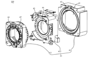
図9および図10に示すように、本願の実施形態は、ロータアセンブリ433と、ステータアセンブリ431と、光学素子46と、を含む走査モジュール40を提供する。ロータアセンブリ433は、収納キャビティ4336が形成されたロータ4331と、ロータ4331の内壁上に設けられ収納キャビティ4336内に位置するボス4332と、を含む。ステータアセンブリ431は、ロータアセンブリ433を駆動してステータアセンブリ431に対して回転させるために用いられる。光学素子46は、収納キャビティ4336内に取り付けられ、ロータアセンブリ433と同期回転する。光学素子46とロータアセンブリ433は同期回転し、光学素子46は、第1の端461と、第2の端462と、を含み、第1の端461と第2の端462は、それぞれ光学素子46の径方向における両端に位置し、第1の端461の厚みは、第2の端462の厚みよりも大きく、第2の端462とボス4332は、対向してロータ4331の回転軸4337の同じ側に位置し、第1の端461とボス4332は、回転軸4337の対向する両側に位置する。 As shown in FIGS. 9 and 10, embodiments herein provide a scanning module 40 that includes a rotor assembly 433, a stator assembly 431, and an optical element 46. As shown in FIGS. The rotor assembly 433 includes a rotor 4331 having a storage cavity 4336 formed therein, and a boss 4332 provided on an inner wall of the rotor 4331 and located within the storage cavity 4336. Stator assembly 431 is used to drive rotor assembly 433 to rotate relative to stator assembly 431 . Optical element 46 is mounted within storage cavity 4336 and rotates synchronously with rotor assembly 433. Optical element 46 and rotor assembly 433 rotate synchronously, optical element 46 includes a first end 461 and a second end 462, and first end 461 and second end 462 each include an optical element. 46, the thickness of the first end 461 is larger than the thickness of the second end 462, and the second end 462 and the boss 4332 are opposite to each other and are located at both ends of the rotor 4331 in the radial direction. Located on the same side, the first end 461 and the boss 4332 are located on opposite sides of the rotating shaft 4337.

図9および図10に示すように、本願の実施形態は、ロータアセンブリ423と、光学素子45と、を含む走査モジュール40を提供する。ロータアセンブリ423は、収納キャビティ4235が形成されたロータ4231を含む。光学素子45は、収納キャビティ4235内に取り付けられ、ロータアセンブリ423と同期回転する。光学素子45は、第1の端451と、第2の端452と、を含み、第1の端451と第2の端452は、それぞれ光学素子45の径方向における両端に位置し、第1の端451の厚みは、第2の端452の厚みよりも大きく、ロータ4231および光学素子45のうちの少なくとも1つの第1の端451に位置する側に切り欠きが形成されている。 As shown in FIGS. 9 and 10, embodiments herein provide a scanning module 40 that includes a rotor assembly 423 and an optical element 45. As shown in FIGS. Rotor assembly 423 includes a rotor 4231 having a storage cavity 4235 formed therein. Optical element 45 is mounted within storage cavity 4235 and rotates synchronously with rotor assembly 423. The optical element 45 includes a first end 451 and a second end 452, the first end 451 and the second end 452 are located at both ends of the optical element 45 in the radial direction, and The thickness of the end 451 is greater than the thickness of the second end 452, and a notch is formed on the side of at least one of the rotor 4231 and the optical element 45 located at the first end 451.

図9および図10に示すように、本願の実施形態は、第1のロータアセンブリ423と、第1の光学素子45と、第2のロータアセンブリ433と、第2の光学素子46と、を含む走査モジュール40を提供する。第1のロータアセンブリ423は、第1の収納キャビティ4235が形成された第1のロータ4231を含む。第1の光学素子45は、第1の収納キャビティ4235内に取り付けられ、第1の光学素子45は、第1の端451と、第2の端452と、を含み、第1の光学素子45の第1の端451と第1の光学素子45の第2の端452は、それぞれ第1の光学素子45の径方向における両端に位置し、第1の光学素子45の第1の端451の厚みは、第1の光学素子45の第2の端452の厚みよりも大きく、第1のロータ4231および第1の光学素子45のうちの少なくとも1つの第1の光学素子45の第1の端451に位置する側に切り欠きが形成されている。第2のロータアセンブリ433は、第2の収納キャビティ4336が形成された第2のロータ4331と、第2のロータ4331の内壁上に設けられ第2の収納キャビティ4336内に位置するボス4332と、を含む。第2の光学素子46は、第2の収納キャビティ4336内に取り付けられ、第2の光学素子46は、第1の端461と、第2の端462と、を含み、第2の光学素子46の第1の端461と第2の光学素子46の第2の端462は、それぞれ第2の光学素子46の径方向における両端に位置し、第2の光学素子46の第1の端461の厚みは、第2の光学素子46の第2の端462の厚みよりも大きく、第2の光学素子46の第2の端462とボス4332は、対向して第2のロータ4331の第2の回転軸4337の同じ側に位置し、第2の光学素子46の第1の端461とボス4332は、第2の回転軸4337の対向する両側に位置する。 As shown in FIGS. 9 and 10, embodiments of the present application include a first rotor assembly 423, a first optical element 45, a second rotor assembly 433, and a second optical element 46. A scanning module 40 is provided. First rotor assembly 423 includes a first rotor 4231 with a first storage cavity 4235 formed therein. A first optical element 45 is mounted within the first storage cavity 4235 , and the first optical element 45 includes a first end 451 and a second end 452, and the first optical element 45 includes a first end 451 and a second end 452. The first end 451 of the first optical element 45 and the second end 452 of the first optical element 45 are located at both ends of the first optical element 45 in the radial direction, respectively. The thickness is greater than the thickness of the second end 452 of the first optical element 45, and the thickness is greater than the thickness of the second end 452 of the first optical element 45 of at least one of the first rotor 4231 and the first optical element 45. A notch is formed on the side located at 451. The second rotor assembly 433 includes a second rotor 4331 in which a second storage cavity 4336 is formed, a boss 4332 provided on an inner wall of the second rotor 4331 and located within the second storage cavity 4336; including. A second optical element 46 is mounted within the second storage cavity 4336 , the second optical element 46 includes a first end 461 and a second end 462 , and the second optical element 46 includes a first end 461 and a second end 462 . The first end 461 of the second optical element 46 and the second end 462 of the second optical element 46 are located at both ends of the second optical element 46 in the radial direction, respectively. The thickness is greater than the thickness of the second end 462 of the second optical element 46, and the second end 462 of the second optical element 46 and the boss 4332 are opposite to each other and the second end 462 of the second rotor 4331 Located on the same side of the rotation axis 4337, the first end 461 of the second optical element 46 and the boss 4332 are located on opposite sides of the second rotation axis 4337.

図1および図9に示すように、本願の実施形態は、上述したいずれかの実施形態の走査モジュール40と、測距モジュール60と、を含む測距装置100を提供する。測距モジュール60は、走査モジュール40にレーザーパルスを発射するために用いられ、走査モジュール40は、レーザーパルスの伝送方向を変えた後に出射するために用いられ、測定物から反射して戻って来たレーザーパルスは、走査モジュール40を経た後、測距モジュール60に入射し、測距モジュール60は、反射して戻って来たレーザーパルスに基づき、測定物と測距装置100との間の距離を確定するために用いられる。 As shown in FIGS. 1 and 9, embodiments of the present application provide a ranging device 100 that includes the scanning module 40 of any of the embodiments described above and a ranging module 60. The ranging module 60 is used to emit a laser pulse to the scanning module 40, and the scanning module 40 is used to emit the laser pulse after changing its transmission direction, and the laser pulse is reflected back from the object to be measured. After passing through the scanning module 40, the laser pulse enters the distance measurement module 60, and the distance measurement module 60 calculates the distance between the object to be measured and the distance measurement device 100 based on the reflected laser pulse. It is used to determine the

本願の走査モジュール40および測距装置100は、ウェッジプリズム自体の重量分布が不均等であるため、ウェッジプリズムを高速回転させるとき走査モジュール40全体が揺動しやすく十分に安定しない可能性があるが、本願では、ロータ4331内にボス4332を設ける方式によってロータアセンブリ433の回転時に生じる揺動を低減することにより、ロータアセンブリ433全体を回転時にさらに安定させることに有利である。または、本願は、ロータ4231および光学素子45のうちの少なくとも1つの第1の端451に位置する側に切り欠きが形成されている方式によってロータアセンブリ423の回転時に生じる揺動を低減することにより、ロータアセンブリ423全体を回転時にさらに安定させることに有利であり、すなわち、測距装置100の振動を無視できるほど少なくし、測距装置100の測距精度を高める。 In the scanning module 40 and distance measuring device 100 of the present application, since the weight distribution of the wedge prism itself is uneven, when the wedge prism is rotated at high speed, the scanning module 40 as a whole tends to swing and may not be sufficiently stable. In the present application, by providing the boss 4332 in the rotor 4331, it is advantageous to reduce the shaking that occurs when the rotor assembly 433 rotates, thereby making the entire rotor assembly 433 more stable during rotation. Alternatively, the present application reduces the rocking that occurs when the rotor assembly 423 rotates by forming a notch on the side of at least one of the rotor 4231 and the optical element 45 located at the first end 451. , it is advantageous to further stabilize the entire rotor assembly 423 during rotation, that is, to reduce the vibration of the ranging device 100 to a negligible extent, and to increase the ranging accuracy of the ranging device 100.

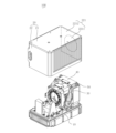
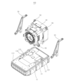
図1および図25に示すように、測距装置100は、台座10と、カバー20と、2つの支持フレーム30と、走査モジュール40と、複数のフレキシブル接続アセンブリ50と、測距モジュール60と、を含む。2つの支持フレーム30は、いずれも台座10上の背を向け合った両側に固定される。走査モジュール40と測距モジュール60は、間隔をあけて台座10上に設けられ、2つの支持フレーム30の間に位置し、支持フレーム30の各々は、少なくとも2つのフレキシブル接続アセンブリ50によって走査モジュール40に接続される。測距モジュール60は、走査モジュール40にレーザーパルスを発射するために用いられ、走査モジュール40は、レーザーパルスの伝送方向を変えた後に出射するために用いられ、測定物から反射して戻って来たレーザーパルスは、走査モジュール40を経た後、測距モジュール60に入射し、測距モジュール60は、反射して戻って来たレーザーパルスに基づき、測定物と測距装置100との間の距離を確定するために用いられる。測距装置100は、測距装置100と測定物との間で光が伝播する時間、すなわち光飛行時間(Time-of-Flight,TOF)を計測することにより、測定物から測距装置100までの距離を測定することができる。または、測距装置100は、例えば、位相シフト(phase shift)測定に基づく測距方法、または周波数シフト(frequency shift)測定に基づく測距方法などの他の技術によって測定物から測距装置100までの距離を測定することもできるが、ここでは限定しない。 As shown in FIGS. 1 and 25, the ranging device 100 includes a base 10, a cover 20, two support frames 30, a scanning module 40, a plurality of flexible connection assemblies 50, a ranging module 60, including. The two support frames 30 are both fixed to opposite sides of the pedestal 10. The scanning module 40 and the ranging module 60 are spaced apart on the pedestal 10 and are located between two support frames 30, each of which is connected to the scanning module 40 by at least two flexible connection assemblies 50. connected to. The ranging module 60 is used to emit a laser pulse to the scanning module 40, and the scanning module 40 is used to emit the laser pulse after changing its transmission direction, and the laser pulse is reflected back from the object to be measured. After passing through the scanning module 40, the laser pulse enters the distance measurement module 60, and the distance measurement module 60 calculates the distance between the object to be measured and the distance measurement device 100 based on the reflected laser pulse. It is used to determine the The distance measuring device 100 measures the time for light to propagate between the distance measuring device 100 and the measured object, that is, the time-of-flight (TOF), so that the distance from the measured object to the distance measuring device 100 is measured. distance can be measured. Alternatively, the ranging device 100 may be configured to use other techniques such as a ranging method based on a phase shift measurement or a ranging method based on a frequency shift measurement from the object to be measured. It is also possible to measure the distance, but this is not limited here.

図2および図3に示すように、台座10は、台座本体11と、第1の装着台12と、第2の装着台13と、を含み、台座本体11は、板状構造を呈する。第1の装着台12および第2の装着台13は、台座本体11の頂部111上に形成される。第1の装着台12は、台座本体11の頂部111から突出して形成された装着壁であってもよく、装着壁には、第1の台座装着穴121があけられており、第1の台座装着穴121の軸線方向は、台座本体11の頂部111に平行である。 As shown in FIGS. 2 and 3, the pedestal 10 includes a pedestal main body 11, a first mounting base 12, and a second mounting base 13, and the pedestal main body 11 has a plate-like structure. The first mounting base 12 and the second mounting base 13 are formed on the top portion 111 of the base body 11. The first mounting base 12 may be a mounting wall formed to protrude from the top 111 of the pedestal main body 11, and the mounting wall is provided with a first pedestal mounting hole 121. The axial direction of the mounting hole 121 is parallel to the top 111 of the base body 11.

図22から図24に示すように、第2の装着台13は、台座本体11の頂部111から突出して形成された台座ボスであってもよく、台座ボス上には、台座装着溝131が設けられており、台座装着溝131の底部には、第2の台座装着穴132があけられており、第2の台座装着穴132の軸線方向は、台座本体11の頂部111に垂直であり、第2の台座装着穴132の軸線方向は、第1の台座装着穴121の軸線方向に垂直である。本実施形態の台座本体11は、矩形板状構造を呈し、第1の装着台12および第2の装着台13の数は、いずれも2つであり、2つの第1の装着台12は、それぞれ台座本体11の対向する両側に位置し、台座本体11の対称面に関して対称であり、2つの第2の装着台13も、それぞれ台座本体11の対向する両側に位置し、台座本体11のこの対称面に関して対称である。同じ側の第1の装着台12および第2の装着台13は、台座本体11の長辺に沿って間隔をあけて設けられ、上述した対称面は、台座本体11の長辺に平行で、台座本体11の短辺に垂直な面である。 As shown in FIGS. 22 to 24, the second mounting base 13 may be a pedestal boss formed to protrude from the top 111 of the pedestal main body 11, and a pedestal mounting groove 131 is provided on the pedestal boss. A second pedestal mounting hole 132 is bored at the bottom of the pedestal mounting groove 131, and the axial direction of the second pedestal mounting hole 132 is perpendicular to the top 111 of the pedestal main body 11. The axial direction of the second pedestal mounting hole 132 is perpendicular to the axial direction of the first pedestal mounting hole 121. The pedestal main body 11 of the present embodiment has a rectangular plate-like structure, and the number of first mounts 12 and second mounts 13 is two, and the two first mounts 12 are The two second mounting bases 13 are also located on opposite sides of the pedestal body 11 and are symmetrical with respect to the plane of symmetry of the pedestal body 11. It is symmetrical about the plane of symmetry. The first mounting base 12 and the second mounting base 13 on the same side are provided at intervals along the long side of the base body 11, and the above-mentioned plane of symmetry is parallel to the long side of the base body 11, This is a surface perpendicular to the short side of the pedestal main body 11.

図1から図3に示すように、カバー20は、台座10上に設けられ、台座10と共同で収容スペースを形成し、カバー20は、カバー頂壁21と、環状のカバー側壁22と、を含む。具体的には、カバー頂壁21は、板状構造を呈し、カバー頂壁21の形状は、台座本体11の形状に合わせてある。本実施例では、カバー頂壁21の形状は、台座10に形状に合わせ、矩形板状構造を呈する。カバー側壁22は、カバー頂壁21の1つの面から延在して形成され、カバー側壁22は、カバー頂壁21の縁に設けられ、カバー頂壁21を囲む。カバー側壁22のカバー頂壁21とは反対の端は、ネジ接続、係合、接着、溶接などの任意の1種または複数種の方式で結合する方式によって台座10上に取り付け、台座本体11の中心を囲むことができる。本実施形態のカバー20は、締付部材14によって台座10上に固定され、さらに具体的には、締付部材14は、台座10の底部側から台座本体11を貫通してカバー側壁22と結合し、締付部材14は、ネジとすることができる。 As shown in FIGS. 1 to 3, the cover 20 is provided on the pedestal 10 and forms an accommodation space together with the pedestal 10, and the cover 20 includes a cover top wall 21 and an annular cover side wall 22. include. Specifically, the cover top wall 21 has a plate-like structure, and the shape of the cover top wall 21 matches the shape of the base body 11. In this embodiment, the cover top wall 21 has a rectangular plate-like structure in accordance with the shape of the pedestal 10. The cover side wall 22 is formed to extend from one surface of the cover top wall 21 , and the cover side wall 22 is provided at the edge of the cover top wall 21 and surrounds the cover top wall 21 . The end of the cover side wall 22 opposite to the cover top wall 21 is attached to the pedestal 10 by any one or more coupling methods such as screw connection, engagement, adhesion, welding, etc. You can surround the center. The cover 20 of this embodiment is fixed on the pedestal 10 by a tightening member 14, and more specifically, the tightening member 14 penetrates the pedestal main body 11 from the bottom side of the pedestal 10 and is coupled to the cover side wall 22. However, the tightening member 14 can be a screw.

カバー側壁22は、第1のカバー側壁221と、第2のカバー側壁222と、を含む。第1のカバー側壁221と第2のカバー側壁222は、カバー頂壁21の対向する両端に位置する。1つの例において、第1のカバー側壁221および第2のカバー側壁222は、それぞれカバー頂壁21の短辺上に設けられる。第1のカバー側壁221には、透光領域2211が形成され、第1のカバー側壁221の透光領域2211以外の領域は非透光領域2212であり、透光領域2211は、測距モジュール60が発する測距信号を通過させるために用いられる。透光領域2211は、プラスチック、樹脂、ガラスなどの光透過率が高い材料により製造することができ、非透光領域2212は、銅、アルミニウムなどの熱伝導性で光透過率が低い金属により製造することができる。好ましくは、透光領域2211は熱伝導性プラスチックを採用し、光透過の要求を満たすことができるだけでなく、放熱の要求を満たすことができる。1つの例において、この透光領域2211は略円形状を呈する。1つの例において、この透光領域2211は略矩形状、例えば方形状を呈する。 The cover side wall 22 includes a first cover side wall 221 and a second cover side wall 222. The first cover side wall 221 and the second cover side wall 222 are located at opposite ends of the cover top wall 21. In one example, the first cover side wall 221 and the second cover side wall 222 are each provided on a short side of the cover top wall 21. A light-transmitting region 2211 is formed on the first cover side wall 221, and a region other than the light-transmitting region 2211 on the first cover side wall 221 is a non-light-transmitting region 2212. It is used to pass the ranging signal emitted by the The light-transmitting region 2211 can be made of a material with high light transmittance, such as plastic, resin, or glass, and the non-light-transmitting region 2212 can be made of a metal with thermal conductivity and low light transmittance, such as copper or aluminum. can do. Preferably, the transparent region 2211 is made of thermally conductive plastic, which can not only meet the requirements of light transmission but also heat dissipation. In one example, the transparent region 2211 has a substantially circular shape. In one example, the transparent region 2211 has a substantially rectangular shape, for example, a square shape.

図3および図4に示すように、支持フレーム30は、台座10上に取り付けられる。本願の実施形態における支持フレーム30の数は2つであり、2つの支持フレーム30は、それぞれ台座10の対向する両側に取り付けられる。支持フレーム30の各々は、いずれも固定アーム31と、接続アーム33と、結合アーム32と、を含む。 As shown in FIGS. 3 and 4, the support frame 30 is mounted on the pedestal 10. The number of support frames 30 in the embodiment of the present application is two, and the two support frames 30 are attached to opposite sides of the base 10, respectively. Each of the support frames 30 includes a fixed arm 31, a connecting arm 33, and a coupling arm 32.

固定アーム31は、複数の固定部310と、第2の結合部313と、を含み、固定アーム31は、複数の固定部310によって台座10上に取り付けられる。本実施形態の固定部310の数は2つであり、2つの固定部310は、それぞれ第1の固定部311および第2の固定部312であり、第1の固定部311および第2の固定部312は、それぞれ固定アーム31の対向する両端に位置し、第1の固定部311および第2の固定部312は、いずれも台座10とリジット接続する。第1の固定部311および第2の固定部312は、固定部材36(例えば締付ネジ)によってそれぞれ台座10の同じ側の第1の装着台12および第2の装着台13上に固定される。具体的には、第1の固定部311は、台座本体11上に設けられ、装着壁側に位置し、固定部材36は、第1の台座装着穴121を貫通して第1の固定部311と結合し、第1の固定部311を第1の装着台12上に固定する。第2の固定部312は、台座装着溝131内に設けられ、固定部材36は、第2の固定部312を貫通して第2の台座装着穴132と結合し、第2の固定部312を第2の装着台13上に取り付ける。第2の結合部313は、第1の固定部311と第2の固定部312との間に位置し、第2の結合部313と台座本体11の頂部111は、間隔があけられ、第2の結合部313上には、支持フレーム装着穴が設けられ、第2の結合部313に設けられた支持フレーム装着穴は、第2の支持フレーム装着穴3131と定義される。 The fixed arm 31 includes a plurality of fixing parts 310 and a second coupling part 313, and the fixed arm 31 is attached onto the base 10 by the plurality of fixing parts 310. The number of fixing parts 310 in this embodiment is two, and the two fixing parts 310 are a first fixing part 311 and a second fixing part 312, respectively. The portions 312 are located at opposite ends of the fixed arm 31, and the first fixed portion 311 and the second fixed portion 312 are both rigidly connected to the base 10. The first fixing part 311 and the second fixing part 312 are fixed onto the first mounting base 12 and the second mounting base 13 on the same side of the base 10, respectively, by a fixing member 36 (for example, a tightening screw). . Specifically, the first fixing part 311 is provided on the pedestal main body 11 and is located on the mounting wall side, and the fixing member 36 penetrates the first pedestal mounting hole 121 and connects to the first fixing part 311. and fixes the first fixing part 311 on the first mounting base 12. The second fixing part 312 is provided in the pedestal mounting groove 131 , and the fixing member 36 penetrates the second fixing part 312 and combines with the second pedestal mounting hole 132 , and the second fixing part 312 is connected to the second fixing part 312 . It is mounted on the second mounting stand 13. The second coupling part 313 is located between the first fixing part 311 and the second fixing part 312, and the second coupling part 313 and the top part 111 of the pedestal main body 11 are spaced apart from each other. A support frame mounting hole is provided on the coupling portion 313 , and the support frame mounting hole provided on the second coupling portion 313 is defined as a second support frame mounting hole 3131 .

接続アーム33の一端は、第1の固定部311上に接続され、接続アーム33の他端は、台座本体11とは反対の方向に延在する。 One end of the connecting arm 33 is connected onto the first fixing part 311, and the other end of the connecting arm 33 extends in the opposite direction to the base body 11.

結合アーム32の一端は、接続アーム33の第1の固定部311とは反対の端に接続し、結合アーム32の他端は、固定アーム31とは反対側に延在する自由端であり、結合アーム32は、台座本体11の頂部111に平行である。結合アーム32の接続アーム33とは反対の端には、第1の結合部321が設けられ、第2の結合部313は、第1の結合部321よりも台座本体11側にある。第1の結合部321上には、支持フレーム装着穴が設けられ、第1の結合部321に設けられた支持フレーム装着穴は、第1の支持フレーム装着穴3211と定義される。1つの例において、第1の固定部311の中心、第2の固定部312の中心、第1の結合部321の中心および第2の結合部313の中心は、同一平面内に位置する。測距装置100が外部からの衝撃を受け振動が生じたときに、支持フレーム30および支持フレーム30に接続した走査モジュール40が受ける回転トルクは比較的小さく、このトルクの方向が固定部310の中心、第1の結合部321の中心および第2の結合部313の中心が所在する平面に垂直であることにより、測距装置100が外部からの衝撃を受けたことによって生じる反転を小さくし、回避することすらできる。 One end of the coupling arm 32 is connected to an end of the coupling arm 33 opposite to the first fixed part 311, and the other end of the coupling arm 32 is a free end extending on the opposite side to the fixed arm 31, The coupling arm 32 is parallel to the top 111 of the base body 11. A first coupling portion 321 is provided at the end of the coupling arm 32 opposite to the connection arm 33, and the second coupling portion 313 is located closer to the pedestal main body 11 than the first coupling portion 321. A support frame mounting hole is provided on the first coupling part 321 , and the support frame mounting hole provided in the first coupling part 321 is defined as a first support frame mounting hole 3211 . In one example, the center of the first fixing part 311, the center of the second fixing part 312, the center of the first coupling part 321, and the center of the second coupling part 313 are located in the same plane. When the ranging device 100 receives an external impact and vibrates, the rotational torque that the support frame 30 and the scanning module 40 connected to the support frame 30 receive is relatively small, and the direction of this torque is the center of the fixed part 310. , since the center of the first coupling part 321 and the center of the second coupling part 313 are perpendicular to the plane, it is possible to reduce and avoid inversion caused when the distance measuring device 100 receives an external impact. You can even do that.

図3、図5、図9および図25に示すように、走査モジュール40は、支持フレーム30によって台座10上に取り付けられ、収容スペース内に収容され、走査モジュール40と台座10は、間隔があけられている。走査モジュール40は、走査ハウジング41と、第1の駆動装置42と、第2の駆動装置43と、第3の駆動装置44と、第1の光学素子45と、第2の光学素子46と、第3の光学素子47と、コントローラ49aと、検出装置49bと、を含む。第1の駆動装置42は、第1の光学素子45を駆動して動かし、第1の光学素子45を経るレーザーパルスの伝送方向を変えるために用いられる。第2の駆動装置43は、第2の光学素子46を駆動して動かし、第2の光学素子46を経るレーザーパルスの伝送方向を変えるために用いられる。第3の駆動装置44は、第3の光学素子47を駆動して動かし、第3の光学素子47を経るレーザーパルスの伝送方向を変えるために用いられる。3つの光学素子(第1の光学素子45、第2の光学素子46および第3の光学素子47)は、互いに協同し合い、光路の伝播方向を変え、走査モジュール40により大きな視野をもたせるために用いることができる。 As shown in FIGS. 3, 5, 9 and 25, the scanning module 40 is mounted on the pedestal 10 by the support frame 30 and housed in the accommodation space, and the scanning module 40 and the pedestal 10 are spaced apart. It is being The scanning module 40 includes a scanning housing 41, a first drive device 42, a second drive device 43, a third drive device 44, a first optical element 45, a second optical element 46, It includes a third optical element 47, a controller 49a, and a detection device 49b. The first drive device 42 is used to drive and move the first optical element 45 and change the direction of transmission of the laser pulse through the first optical element 45 . The second drive device 43 is used to drive and move the second optical element 46 and change the direction of transmission of the laser pulse through the second optical element 46 . The third drive device 44 is used to drive and move the third optical element 47 and change the direction of transmission of the laser pulse through the third optical element 47 . The three optical elements (first optical element 45, second optical element 46 and third optical element 47) cooperate with each other to change the propagation direction of the optical path and provide the scanning module 40 with a larger field of view. Can be used.

1つの例において、第1の光学素子45、第2の光学素子46および第3の光学素子47は、レンズ、反射ミラー、プリズム、ガルバノミラー、回折格子、液晶、光フェーズドアレー(Optical Phased Array)または上述した光学素子の任意の組み合わせを含むことができる。1つの例において、第1の光学素子45、第2の光学素子46および第3の光学素子47のうち少なくとも1つの光学素子は、出光面と入光面が平行でない光屈折素子であり、この光屈折素子が回転するときに、光束を異なる方向に屈折させて出射することができる。1つの例において、この光屈折素子は、楔形プリズムである。 In one example, the first optical element 45, the second optical element 46, and the third optical element 47 are lenses, reflective mirrors, prisms, galvano mirrors, diffraction gratings, liquid crystals, and optical phased arrays. Or it can include any combination of the optical elements described above. In one example, at least one of the first optical element 45, the second optical element 46, and the third optical element 47 is a light refractive element whose light exit surface and light entrance surface are not parallel; When the light refraction element rotates, the light beam can be refracted in different directions and emitted. In one example, the light refractive element is a wedge prism.

1つの例において、少なくとも一部の光学素子(第1の光学素子45、第2の光学素子46および第3の光学素子47)は、動き、例えば、駆動装置(第1の駆動装置42、第2の駆動装置43および第3の駆動装置44)によりこの少なくとも一部の光学素子を駆動して動かし、この動く光学素子は、異なる時間に光束を異なる方向に反射、屈折または回折することができる。いくつかの実施例において、走査モジュール40の複数の光学素子は、共通の軸の周りを回転または振動することができ、回転または振動する光学素子の各々は、入射光束の伝播方向を絶えず変えるために用いられる。1つの実施例において、走査モジュール40の複数の光学素子は、異なる回転速度で回転するか、または異なる速度で振動することができる。別の実施例において、走査モジュール40の少なくとも一部の光学素子は、基本的に同じ回転速度で回転することができる。いくつかの実施例において、走査モジュールの複数の光学素子は、異なる軸の周りを回転してもよい。いくつかの実施例において、走査モジュール40の複数の光学素子は、同じ方向に回転しても、異なる方向に回転してもよく、同じ方向に振動しても、異なる方向に振動してもよく、ここでは限定しない。 In one example, at least some of the optical elements (first optical element 45, second optical element 46 and third optical element 47) move, e.g. a second driving device 43 and a third driving device 44) drive and move the at least some of the optical elements, and the moving optical elements can reflect, refract or diffract the light beam in different directions at different times. . In some embodiments, the plurality of optical elements of scanning module 40 can rotate or oscillate about a common axis, with each rotating or oscillating optical element constantly changing the direction of propagation of the incident light beam. used for. In one example, the multiple optical elements of scanning module 40 can rotate at different rotational speeds or oscillate at different speeds. In another example, at least some optical elements of scanning module 40 may rotate at essentially the same rotational speed. In some embodiments, multiple optical elements of a scanning module may rotate about different axes. In some embodiments, the plurality of optical elements of scanning module 40 may rotate in the same direction or in different directions, and may oscillate in the same direction or in different directions. , is not limited here.

第1の駆動装置42、第2の駆動装置43および第3の駆動装置44は、光学素子(第1の光学素子45、第2の光学素子46および第3の光学素子47)の回転、振動、所定の軌跡に沿った循環移動または所定の軌跡に沿った往復移動を駆動することができ、ここでは限定しない。以下、光学素子(第1の光学素子45、第2の光学素子46および第3の光学素子47)がプリズムを含む例によって、例を挙げて記述する。 The first drive device 42, the second drive device 43, and the third drive device 44 rotate and vibrate the optical elements (first optical element 45, second optical element 46, and third optical element 47). , a circular movement along a predetermined trajectory or a reciprocating movement along a predetermined trajectory can be driven, and is not limited here. Hereinafter, an example will be described based on an example in which the optical elements (first optical element 45, second optical element 46, and third optical element 47) include a prism.

走査ハウジング41は、走査モジュール40のケースとすることができ、走査ハウジング41内は、第1の駆動装置42、第2の駆動装置43、第3の駆動装置44、第1の光学素子45、第2の光学素子46、第3の光学素子47、コントローラ49aおよび検出装置49bなどの素子を取り付けるために用いることができる。走査ハウジング41は、一体の全体構造であってもよく、走査ハウジング41は、複数の分離構造を組み合わせてなってもよく、例えば、図6から図8に示すように、走査ハウジング41は、第1の支持ベース411、第2の支持ベース412および第3の支持ベース413のうち少なくとも任意の2つを含むとともに、さらに第1の取り付け部414と、第2の取り付け部415と、を含んでもよい。例えば、走査ハウジング41は、第1の取り付け部414と、第2の取り付け部415と、第1の支持ベース411と、第2の支持ベース412と、を含むか、または、走査ハウジング41は、第1の取り付け部414と、第2の取り付け部415と、第2の支持ベース412と、第3の支持ベース413と、を含むか、または、走査ハウジング41は、第1の取り付け部414と、第2の取り付け部415と、第1の支持ベース411と、第3の支持ベース413と、を含むか、または、走査ハウジング41は、第1の取り付け部414と、第2の取り付け部415と、第1の支持ベース411と、第2の支持ベース412と、第3の支持ベース413と、を含む。以下、走査ハウジング41が、第1の取り付け部414と、第2の取り付け部415と、第1の支持ベース411と、第2の支持ベース412と、第3の支持ベース413と、を含むもののみを例として記述する。 The scanning housing 41 can be a case for the scanning module 40, and inside the scanning housing 41 are a first drive device 42, a second drive device 43, a third drive device 44, a first optical element 45, It can be used to attach elements such as the second optical element 46, the third optical element 47, the controller 49a, and the detection device 49b. The scan housing 41 may be a unitary overall structure, or the scan housing 41 may be a combination of multiple separate structures; for example, as shown in FIGS. 6 to 8, the scan housing 41 may include a The first support base 411 , the second support base 412 , and the third support base 413 include at least any two of them, and may further include a first attachment part 414 and a second attachment part 415 . good. For example, the scan housing 41 includes a first attachment portion 414, a second attachment portion 415, a first support base 411, and a second support base 412, or the scan housing 41 includes: Alternatively, the scan housing 41 includes a first mounting portion 414 , a second mounting portion 415 , a second support base 412 , and a third support base 413 . , a second attachment portion 415 , a first support base 411 , and a third support base 413 , or the scan housing 41 includes a first attachment portion 414 and a second attachment portion 415 . , a first support base 411 , a second support base 412 , and a third support base 413 . Hereinafter, the scanning housing 41 includes a first attachment part 414, a second attachment part 415, a first support base 411, a second support base 412, and a third support base 413. This is only described as an example.

図5から図8に示すように、第1の支持ベース411は、第1の駆動装置42および第1の光学素子45を取り付けるために用いることができる。第1の支持ベース411は、走査ハウジング41上の測距モジュール60から最も遠い1つの支持ベースとすることができる。第1の支持ベース411は、第1の支持ベース本体4111を含む。第1の支持ベース本体4111は、中空の構造とし、中空の部分に第1の収容キャビティ4119を形成することができる。本願の実施例では、第1の支持ベース本体4111の外輪郭全体が矩形を呈し、中空部分の形状は円形とすることができ、第1の駆動装置42および第1の光学素子45は、第1の収容キャビティ4119内に取り付けることができる。本願の実施例では、第1の支持ベース本体4111は、第1の支持ベース頂面4115と、2つの第1の支持ベース側面4116と、を含み、2つの第1の支持ベース側面4116は、それぞれ第1の支持ベース本体4111の背を向け合った両側に位置し、第1の支持ベース頂面4115に接続される。第1の支持ベース頂面4115には、支持ベース装着溝4117が設けられ、支持ベース装着溝4117の底面には、ハウジング装着穴が設けられ、支持ベース装着溝4117の底面に設けられたハウジング装着穴は、第1のハウジング装着穴4118と定義される。 As shown in FIGS. 5-8, the first support base 411 can be used to mount the first drive device 42 and the first optical element 45. As shown in FIGS. The first support base 411 may be the one support base furthest from the ranging module 60 on the scanning housing 41 . The first support base 411 includes a first support base body 4111. The first support base body 4111 may have a hollow structure, and a first accommodation cavity 4119 may be formed in the hollow portion. In the embodiment of the present application, the entire outer contour of the first support base body 4111 may be rectangular, the shape of the hollow portion may be circular, and the first drive device 42 and the first optical element 45 may be 1 receiving cavity 4119. In the embodiment of the present application, the first support base body 4111 includes a first support base top surface 4115 and two first support base side surfaces 4116, and the two first support base side surfaces 4116 are: They are respectively located on opposite sides of the first support base main body 4111 and connected to the first support base top surface 4115. The first support base top surface 4115 is provided with a support base mounting groove 4117, the bottom surface of the support base mounting groove 4117 is provided with a housing mounting hole, and the bottom surface of the support base mounting groove 4117 is provided with a housing mounting hole. The hole is defined as first housing mounting hole 4118.

第2の支持ベース412は、第2の駆動装置43および第2の光学素子46を取り付けるために用いることができる。第2の支持ベース412は、第1の支持ベース411と互いに係合することができ、例えば第2の支持ベース412を第1の支持ベース411内に覆設し、第2の支持ベース412は、第1の支持ベース411と同じ軸に設けても、異なる軸に設けてもよい。ここで、第2の支持ベース412を第1の支持ベース411と同じ軸に設けるとは、第2の支持ベース412の中軸線と第1の支持ベース411の中軸線とが重なり合うことをいい、異なる軸に設けるとは、第2の支持ベース412の中軸線と第1の支持ベース411の中軸線とが重なり合わないことをいい、例えば平行に間隔をあけているか、または任意の角度で交わる。第2の支持ベース412は、第2の支持ベース本体4121および突出部4120を有する。1つの例において、突出部4120は、第2の支持ベース412を支持フレーム30上に取り付けるために用いることができる。第2の支持ベース本体4121は、中空の構造とし、中空の部分に第2の収容キャビティ4126を形成することができる。第2の駆動装置43および第2の光学素子46は、第2の収容キャビティ4126内に取り付けることができる。本願の実施例では、第2の支持ベース本体4121は、第2の支持ベース底面41211と、2つの第2の支持ベース側面41212と、を含み、2つの第2の支持ベース側面41212は、それぞれ第2の支持ベース本体4121の背を向け合った両側に位置し、第2の支持ベース底面41211に接続され、2つの第2の支持ベース側面41212は、それぞれ2つの第1の支持ベース側面4116に対応する。1つの例において、突出部4120は、第1の支持ベース本体4111の第2の支持ベース底面41211に近い位置に設けることができ、突出部4120は、第2の支持ベース側面41212の第2の支持ベース底面41211に近い位置から外に向かって延在して形成されると理解することができる。突出部4120には、ハウジング装着穴が設けられ、突出部4120に設けられたハウジング装着穴は、第2のハウジング装着穴41201と定義される。 A second support base 412 can be used to mount a second drive 43 and a second optical element 46. The second support base 412 is capable of interengaging with the first support base 411, e.g. , may be provided on the same axis as the first support base 411, or may be provided on a different axis. Here, providing the second support base 412 on the same axis as the first support base 411 means that the center axis of the second support base 412 and the center axis of the first support base 411 overlap, Providing on different axes means that the center axis of the second support base 412 and the center axis of the first support base 411 do not overlap; for example, they are parallel to each other at an interval, or they intersect at an arbitrary angle. . The second support base 412 has a second support base body 4121 and a protrusion 4120. In one example, protrusion 4120 can be used to attach second support base 412 onto support frame 30. The second support base body 4121 may have a hollow structure, and a second accommodation cavity 4126 may be formed in the hollow portion. The second drive device 43 and the second optical element 46 can be mounted within the second receiving cavity 4126. In the embodiment of the present application, the second support base main body 4121 includes a second support base bottom surface 41211 and two second support base side surfaces 41212, and each of the two second support base side surfaces 41212 is Located on opposite sides of the second support base main body 4121 and connected to the second support base bottom surface 41211, the two second support base side surfaces 41212 are respectively connected to the two first support base side surfaces 4116 corresponds to In one example, the protrusion 4120 may be provided at a position close to the second support base bottom surface 41211 of the first support base body 4111, and the protrusion 4120 may be provided at a position close to the second support base bottom surface 41211 of the first support base body 4111. It can be understood that it is formed extending outward from a position close to the bottom surface 41211 of the support base. The protrusion 4120 is provided with a housing attachment hole, and the housing attachment hole provided in the protrusion 4120 is defined as a second housing attachment hole 41201.

第3の支持ベース413は、第3の駆動装置44および第3の光学素子47を取り付けるために用いることができる。第3の支持ベース413は、第2の支持ベース412と互いに係合することができ、第3の支持ベース413は、第2の支持ベース412内に覆設することができ、第3の支持ベース413は、第2の支持ベース412と同じ軸に設けても、異なる軸に設けてもよい。第3の支持ベース413は、第3の支持ベース本体4130を含み、第3の支持ベース本体4130は、中空の構造とし、中空の部分に第3の収容キャビティ4134を形成することができる。第3の駆動装置44および第3の光学素子47は、第3の収容キャビティ4134内に取り付けることができる。第3の支持ベース413と第1の支持ベース411は、それぞれ第2の支持ベース412の背を向け合った両側に設けることができ、測距モジュール60から発射された光パルスは、順に第3の支持ベース413、第2の支持ベース412および第1の支持ベース411を通過した後、外部に出る。被測定物から反射した光パルスは、順に第1の支持ベース411、第2の支持ベース412および第3の支持ベース413を通過した後、測距モジュール60によって受光される。第3の支持ベース本体4130は、背を向け合った2つの第3の支持ベース側面4133を含む。このとき、第1の支持ベース411の背を向け合った両側は、第2の支持ベース412に対応する背を向け合った両側および第3の支持ベース413に対応する背を向け合った両側に対していずれも突出し、2つの装着スペース416を形成する。第3の支持ベース413の背を向け合った両側は、第2の支持ベース412に対応する背を向け合った両側を超えて出ていなくてもよく、本実施例では、第3の支持ベース413の背を向け合った両側は、それぞれ第2の支持ベース412に対応する背を向け合った両側と面一である。第3の支持ベース413の背を向け合った両側が第2の支持ベース412の対応する背を向け合った両側を超えて出ていないことにより、第2の装着台13を装着スペース416内に形成するのに便利である。他の実施形態では、第3の支持ベース413の背を向け合った両側が第2の支持ベース412の対応する背を向け合った両側を超えて出ていてもよく、これにより、第1の装着台12を装着スペース416内に形成するのに便利である。 A third support base 413 can be used to mount a third drive 44 and a third optical element 47. The third support base 413 can be interengaged with the second support base 412, and the third support base 413 can be overridden within the second support base 412, and the third support base 413 can be recessed within the second support base 412. The base 413 may be provided on the same axis as the second support base 412, or may be provided on a different axis. The third support base 413 includes a third support base body 4130, which may have a hollow structure and form a third accommodation cavity 4134 in the hollow portion. The third drive device 44 and the third optical element 47 can be mounted within the third receiving cavity 4134. The third support base 413 and the first support base 411 can be provided on opposite sides of the second support base 412, respectively, and the light pulse emitted from the ranging module 60 is transmitted to the third support base 411 in turn. After passing through the support base 413, the second support base 412, and the first support base 411, it exits to the outside. The light pulse reflected from the object to be measured passes through the first support base 411 , the second support base 412 , and the third support base 413 in this order, and then is received by the ranging module 60 . The third support base body 4130 includes two third support base sides 4133 facing each other. At this time, both sides of the first support base 411 whose backs are facing each other are opposite sides of the second support base 412 and both sides whose backs are facing each other correspond to the third support base 413. Both protrude to form two mounting spaces 416. The opposite sides of the third support base 413 do not need to protrude beyond the opposite sides of the second support base 412, and in this embodiment, the third support base The opposite sides of 413 are flush with the corresponding opposite sides of second support base 412, respectively. Since both sides of the third support base 413 whose backs are facing each other do not protrude beyond the corresponding sides of the second support base 412 whose backs are facing each other, the second mounting base 13 can be placed inside the mounting space 416. Convenient to form. In other embodiments, opposite sides of the third support base 413 may extend beyond corresponding opposite sides of the second support base 412, thereby It is convenient to form the mounting base 12 within the mounting space 416.

第1の取り付け部414は、第1の支持ベース411の台座10とは反対の端に位置していてもよく、具体的には、第1の取り付け部414は、第1の支持ベース本体4111の第1の支持ベース頂面4115に近い位置にある。第1の取り付け部414は、第1の支持ベース411を支持フレーム30上に取り付けるために用いられる。本願の第1の取り付け部414は、第1の支持ベース本体4111の一部であってもよく、具体的には、第1の取り付け部414は、第1の支持ベース本体4111上の支持ベース装着溝4117および第1のハウジング装着穴4118を形成する構造であると理解することができる。他の実施形態では、第1の取り付け部414は、第1の支持ベース本体4111上に設けられたフランジであってもよく、このフランジには、第1のハウジング装着穴4118が設けられる。 The first attachment part 414 may be located at the end of the first support base 411 opposite to the pedestal 10, and specifically, the first attachment part 414 is attached to the first support base body 4111. is located close to the first support base top surface 4115 of. The first attachment part 414 is used to attach the first support base 411 onto the support frame 30. The first attachment part 414 of the present application may be a part of the first support base body 4111, and specifically, the first attachment part 414 is attached to the support base on the first support base body 4111. It can be understood that this is a structure that forms a mounting groove 4117 and a first housing mounting hole 4118. In other embodiments, the first attachment portion 414 may be a flange provided on the first support base body 4111, and the flange is provided with a first housing mounting hole 4118.

第2の取り付け部415は、第2の支持ベース412の台座10に近い端に位置し、具体的には、第2の取り付け部415は、第2の支持ベース本体4121の第2の支持ベース底面41211に近い位置にある。第2の装着台13は、第2の支持ベース412を支持フレーム30上に取り付けるために用いられる。本願の第2の取り付け部415は、第2の支持ベース412の一部であってもよく、具体的には、第2の取り付け部415は、突出部4120とすることができる。走査ハウジング41は、第1の装着台12および第2の装着台13によって支持フレーム30上に取り付けられる。 The second attachment part 415 is located at the end of the second support base 412 near the pedestal 10, and specifically, the second attachment part 415 is located at the end of the second support base body 4121. It is located close to the bottom surface 41211. The second mounting base 13 is used to attach the second support base 412 onto the support frame 30. The second attachment portion 415 of the present application may be a part of the second support base 412, and specifically, the second attachment portion 415 may be a protrusion 4120. Scanning housing 41 is mounted on support frame 30 by first mount 12 and second mount 13 .

図5、図9および図10に示すように、第1の駆動装置42は、走査ハウジング41内に取り付けられ、具体的には、第1の駆動装置42は、第1の収容キャビティ4119内に取り付けることができる。第1の駆動装置42は、第1のステータアセンブリ421と、第1の位置決めアセンブリ422と、第1のロータアセンブリ423と、を含む。第1のステータアセンブリ421は、第1の支持ベース本体4111に相対的に固定することができ、第1のステータアセンブリ421は、第1のロータアセンブリ423を駆動して回転させるために用いることができ、第1のステータアセンブリ421は、第1の巻線本体と、第1の巻線本体上に取り付けられた第1の巻線と、を含む。ここで、第1の巻線本体は、ステータコアとすることができ、第1の巻線は、コイルとすることができる。第1の巻線は、電流の作用の下で特定の磁界を発生させることができ、電流の方向および強度を変えることにより、磁界の方向および強度を変えることができる。第1のステータアセンブリ421は、第1のロータアセンブリ423上に覆設される。 As shown in FIGS. 5, 9 and 10, the first drive device 42 is mounted within the scanning housing 41, and specifically the first drive device 42 is mounted within the first receiving cavity 4119. Can be installed. First drive device 42 includes a first stator assembly 421 , a first positioning assembly 422 , and a first rotor assembly 423 . The first stator assembly 421 can be fixed relative to the first support base body 4111, and the first stator assembly 421 can be used to drive the first rotor assembly 423 to rotate. The first stator assembly 421 includes a first winding body and a first winding mounted on the first winding body. Here, the first winding body can be a stator core, and the first winding can be a coil. The first winding can generate a certain magnetic field under the action of an electric current, and by changing the direction and intensity of the current, the direction and intensity of the magnetic field can be changed. First stator assembly 421 is overlaid on first rotor assembly 423 .

第1のロータアセンブリ423は、第1のステータアセンブリ421の駆動の下で回転することができる。具体的には、第1のロータアセンブリ423は、第1のロータ4231を含み、第1のロータ4231が第1のステータアセンブリ421に対して回転する軸線を第1の回転軸4236といい、第1の回転軸4236は、物理的な回転軸であっても、仮想的な回転軸であってもよいと理解することができる。第1のロータ4231は、第1のヨーク4233aと、第1の磁石4233bと、を含む。第1の磁石4233bは、第1のヨーク4233a上に覆設され、第1のヨーク4233aと第1の巻線との間に位置し、第1の磁石4233bが生じる磁界は、第1の巻線が生じる磁界と相互作用して作用力を生じ、第1の巻線は固定され動かないため、第1の磁石4233bは作用力の下で第1のヨーク4233aを動かし回転させる。第1のロータ4231は、中空の形状を呈し、第1のロータ4231の中空の部分には、第1の収納キャビティ4235が形成され、レーザーパルスは、第1の収納キャビティ4235を通って走査モジュール40の中を通ることができる。具体的には、第1の収納キャビティ4235は、第1のロータ4231の第1の側壁4234によって囲まれ、さらに具体的には、本願の実施形態では、第1のヨーク4233aは中空の筒状を呈し、第1のヨーク4233aの中空の部分が第1の収納キャビティ4235を形成していてもよく、第1のヨーク4233aの側壁は、第1の収納キャビティ4235を囲む側壁とすることができる。当然ながら、他の実施形態では、第1の収納キャビティ4235は、第1のヨーク4233a上に形成されていなくてもよく、第1の磁石4233bなどの構造上に形成されていてもよく、第1の側壁4234は、第1の磁石4233bなどの構造の側壁であってもよく、ここでは限定しない。第1の側壁4234は、環状構造を呈するか、または1つの環状構造の一部である。第1のステータアセンブリ421の第1の巻線は、環状を呈して第1の側壁4234の外面に巻かれていてもよい。 The first rotor assembly 423 can rotate under the drive of the first stator assembly 421. Specifically, the first rotor assembly 423 includes a first rotor 4231, an axis along which the first rotor 4231 rotates with respect to the first stator assembly 421 is referred to as a first rotation axis 4236, and a first rotor 4231 includes a first rotor 4231. It can be understood that the rotation axis 4236 of No. 1 may be a physical rotation axis or a virtual rotation axis. The first rotor 4231 includes a first yoke 4233a and a first magnet 4233b. The first magnet 4233b is placed over the first yoke 4233a and is located between the first yoke 4233a and the first winding, and the magnetic field generated by the first magnet 4233b is applied to the first winding. The wire interacts with the generated magnetic field to create an acting force, and since the first winding is fixed and unmovable, the first magnet 4233b moves and rotates the first yoke 4233a under the acting force. The first rotor 4231 has a hollow shape, and a first accommodation cavity 4235 is formed in the hollow part of the first rotor 4231, and the laser pulse passes through the first accommodation cavity 4235 to the scanning module. You can pass through 40. Specifically, the first storage cavity 4235 is surrounded by a first sidewall 4234 of the first rotor 4231, and more specifically, in the present embodiment, the first yoke 4233a is a hollow cylindrical The hollow portion of the first yoke 4233a may form a first storage cavity 4235, and the side wall of the first yoke 4233a may be a side wall surrounding the first storage cavity 4235. . Of course, in other embodiments, the first storage cavity 4235 may not be formed on the first yoke 4233a, but may be formed on a structure such as the first magnet 4233b, and the first storage cavity 4235 may be formed on a structure such as the first magnet 4233b. The first side wall 4234 may be a side wall of a structure such as the first magnet 4233b, and is not limited here. The first sidewall 4234 exhibits an annular structure or is part of an annular structure. The first winding of the first stator assembly 421 may have an annular shape and be wound around the outer surface of the first side wall 4234.

第1の位置決めアセンブリ422は、第1の側壁4234の外面に位置し、第1の位置決めアセンブリ422は、第1のロータアセンブリ423を制限して、固定された第1の回転軸4236を中心として回転させるために用いられる。第1のステータアセンブリ421および第1の位置決めアセンブリ422は、並列して第1の側壁4234の外面に巻かれる。第1の位置決めアセンブリ422は、環状の第1の軸受422を含み、第1の軸受422は、第1の側壁4234の外面に巻かれる。第1の軸受422は、第1の内周構造4221と、第1の外周構造4222と、第1の転がり体4223と、を含む。第1の内周構造4221と第1の側壁4234の外面は、互いに固定される。第1の外周構造4222と走査ハウジング41は互いに固定され、具体的には、第1の外周構造4222と第1の支持ベース411が互いに固定される。第1の転がり体4223は、第1の内周構造4221と第1の外周構造4222との間に位置し、第1の転がり体4223は、それぞれ第1の外周構造4222および第1の内周構造4221と転がり接続するために用いられる。 A first positioning assembly 422 is located on the outer surface of the first sidewall 4234, and the first positioning assembly 422 constrains the first rotor assembly 423 about a fixed first axis of rotation 4236. Used for rotation. The first stator assembly 421 and the first positioning assembly 422 are wrapped around the outer surface of the first sidewall 4234 in parallel. First positioning assembly 422 includes an annular first bearing 422 that is wrapped around an outer surface of first sidewall 4234 . The first bearing 422 includes a first inner circumferential structure 4221, a first outer circumferential structure 4222, and a first rolling body 4223. The outer surfaces of the first inner peripheral structure 4221 and the first side wall 4234 are fixed to each other. The first outer structure 4222 and the scanning housing 41 are fixed to each other, and specifically, the first outer structure 4222 and the first support base 411 are fixed to each other. The first rolling body 4223 is located between the first inner circumferential structure 4221 and the first outer circumferential structure 4222, and the first rolling body 4223 is located between the first outer circumferential structure 4222 and the first inner circumferential structure, respectively. Used for rolling connection with structure 4221.

第1の光学素子45は、第1の収納キャビティ4235内に取り付けられ、具体的には、第1の光学素子45は、第1の側壁4234と係合して取り付けられ、第1のロータ4231と固定接続され、第1の光学素子45は、レーザーパルスの出射および入射光路上に位置する。第1の光学素子45は、第1の回転軸4236の周りで第1のロータ4231と同期回転することができる。第1の光学素子45は、回転時に、第1の光学素子45を経るレーザーの伝送方向を変えることができる。 The first optical element 45 is mounted within the first storage cavity 4235, and specifically, the first optical element 45 is mounted in engagement with the first sidewall 4234 and the first optical element 45 is mounted in the first rotor 4231. , and the first optical element 45 is located on the output and input optical path of the laser pulse. The first optical element 45 can rotate synchronously with the first rotor 4231 around a first rotation axis 4236. The first optical element 45 can change the direction of laser transmission through the first optical element 45 when rotated.

第2の駆動装置43は、走査ハウジング41内に取り付けられ、具体的には、第2の駆動装置43は、第2の収容キャビティ4126内に取り付けることができ、第2の駆動装置43は、第2のステータアセンブリ431と、第2の位置決めアセンブリ432と、第2のロータアセンブリ433と、を含む。第2のステータアセンブリ431は、第2の支持ベース本体4121と相対的に固定することができ、第2のステータアセンブリ431は、第2のロータアセンブリ433を駆動して回転させるために用いることができ、第2のステータアセンブリ431は、第2の巻線本体と、第2の巻線本体上に取り付けられた第2の巻線と、を含む。ここで、第2の巻線本体は、ステータコアとすることができ、第2の巻線は、コイルとすることができる。第2の巻線は、電流の作用の下で特定の磁界を発生させることができ、電流の方向および強度を変えることにより、磁界の方向および強度を変えることができる。 The second drive device 43 is mounted within the scanning housing 41, specifically the second drive device 43 can be mounted within the second receiving cavity 4126, and the second drive device 43 is mounted within the scanning housing 41. It includes a second stator assembly 431, a second positioning assembly 432, and a second rotor assembly 433. The second stator assembly 431 can be fixed relative to the second support base body 4121, and the second stator assembly 431 can be used to drive the second rotor assembly 433 to rotate. The second stator assembly 431 includes a second winding body and a second winding mounted on the second winding body. Here, the second winding body can be a stator core, and the second winding can be a coil. The second winding can generate a certain magnetic field under the action of an electric current, and by changing the direction and intensity of the current, the direction and intensity of the magnetic field can be changed.

第2のロータアセンブリ433は、第2のステータアセンブリ431の駆動の下で回転することができる。具体的には、第2のロータアセンブリ433は、第2のロータ4331を含み、第2のロータ4331が第2のステータアセンブリ431に対して回転する軸線を第2の回転軸4337といい、第2の回転軸4337は、物理的な回転軸であっても、仮想的な回転軸であってもよいと理解することができる。第2のロータ4331は、第2のヨーク4333と、第2の磁石4334と、を含む。第2の磁石4334は、第2のヨーク4333上に覆設され、第2のヨーク4333と第2の巻線との間に位置し、第2の磁石4334が生じる磁界は、第2の巻線が生じる磁界と相互作用して作用力を生じ、第2の巻線は固定されて動かないため、第2の磁石4334は作用力の下で第2のヨーク4333を動かし回転させる。第2のロータ4331は、中空の形状を呈し、第2のロータ4331の中空の部分には、第2の収納キャビティ4336が形成され、レーザーパルスは、第2の収納キャビティ4336を通って走査モジュール40の中を通ることができる。具体的には、第2の収納キャビティ4336は、第2のロータ4331の第2の側壁4335によって囲まれ、さらに具体的には、本願の実施形態では、第2のヨーク4333は中空の筒状を呈し、第2のヨーク4333の中空の部分が第2の収納キャビティ4336を形成していてもよく、第2のヨーク4333の側壁は、第2の収納キャビティ4336を囲む側壁とすることができる。当然ながら、他の実施形態では、第2の収納キャビティ4336は、第2のヨーク4333上に形成されていなくてもよく、第2の磁石4334などの構造上に形成されていてもよく、第2の側壁4335は、第2の磁石4334などの構造の側壁であってもよく、ここでは限定しない。第2の側壁4335は、環状構造を呈するか、または1つの環状構造の一部である。第2のステータアセンブリ431の第2の巻線は、環状を呈して第2の側壁4335の外面に巻かれていてもよい。 The second rotor assembly 433 can rotate under the drive of the second stator assembly 431. Specifically, the second rotor assembly 433 includes a second rotor 4331, and the axis along which the second rotor 4331 rotates with respect to the second stator assembly 431 is referred to as a second rotation axis 4337. It can be understood that the rotation axis 4337 of No. 2 may be a physical rotation axis or a virtual rotation axis. The second rotor 4331 includes a second yoke 4333 and a second magnet 4334. The second magnet 4334 is placed over the second yoke 4333 and is located between the second yoke 4333 and the second winding, and the magnetic field generated by the second magnet 4334 is applied to the second winding. The wire interacts with the generated magnetic field to create an acting force, and since the second winding is fixed and does not move, the second magnet 4334 moves and rotates the second yoke 4333 under the acting force. The second rotor 4331 has a hollow shape, and a second accommodation cavity 4336 is formed in the hollow part of the second rotor 4331, and the laser pulse passes through the second accommodation cavity 4336 to the scanning module. You can pass through 40. Specifically, the second storage cavity 4336 is surrounded by a second sidewall 4335 of the second rotor 4331, and more specifically, in the present embodiment, the second yoke 4333 is a hollow cylindrical The hollow portion of the second yoke 4333 may form a second storage cavity 4336, and the side wall of the second yoke 4333 may be a side wall surrounding the second storage cavity 4336. . Of course, in other embodiments, the second storage cavity 4336 may not be formed on the second yoke 4333, but may be formed on a structure such as the second magnet 4334, The second side wall 4335 may be a side wall of a structure such as the second magnet 4334, and is not limited here. The second sidewall 4335 exhibits an annular structure or is part of an annular structure. The second winding of the second stator assembly 431 may have an annular shape and be wound around the outer surface of the second side wall 4335.

第2の位置決めアセンブリ432は、第2のロータ4331上に設けられ、第2のステータアセンブリ431の第1のロータアセンブリ423とは反対側に位置する。第2の位置決めアセンブリ432は、第2のロータアセンブリ433を制限して、固定された第2の回転軸4337を中心として回転させるために用いられる。第2のステータアセンブリ431および第2の位置決めアセンブリ432は、並列して第2の側壁4335の外面に巻かれる。第2の位置決めアセンブリ432は、環状の第2の軸受432を含み、第2の軸受432は、第2の側壁4335の外面に巻かれる。第2の軸受432は、第2の内周構造4321と、第2の外周構造4322と、第2の転がり体4323と、を含む。第2の内周構造4321と第2の側壁4335の外面は、互いに固定される。第2の外周構造4322と走査ハウジング41は互いに固定され、具体的には、第2の外周構造4322と第2の支持ベース412が互いに固定される。第2の転がり体4323は、第2の内周構造4321と第2の外周構造4322との間に位置し、第2の転がり体4323は、それぞれ第2の外周構造4322および第2の内周構造4321と転がり接続するために用いられる。 A second positioning assembly 432 is provided on the second rotor 4331 and is located on the opposite side of the second stator assembly 431 from the first rotor assembly 423 . The second positioning assembly 432 is used to constrain the second rotor assembly 433 to rotate about a fixed second axis of rotation 4337. A second stator assembly 431 and a second positioning assembly 432 are wrapped around the outer surface of the second sidewall 4335 in parallel. The second positioning assembly 432 includes an annular second bearing 432 that is wrapped around the outer surface of the second sidewall 4335. The second bearing 432 includes a second inner peripheral structure 4321, a second outer peripheral structure 4322, and a second rolling body 4323. The outer surfaces of the second inner peripheral structure 4321 and the second side wall 4335 are fixed to each other. The second outer structure 4322 and the scanning housing 41 are fixed to each other, and specifically, the second outer structure 4322 and the second support base 412 are fixed to each other. The second rolling body 4323 is located between the second inner circumferential structure 4321 and the second outer circumferential structure 4322, and the second rolling body 4323 is located between the second outer circumferential structure 4322 and the second inner circumferential structure, respectively. Used for rolling connection with structure 4321.

第2の光学素子46は、第2の収納キャビティ4336内に取り付けられ、具体的には、第2の光学素子46は、第2の側壁4335と係合して取り付けられ、第2のロータ4331と固定接続され、第2の光学素子46は、光源の出射光路上およびエコーの入射光路上に位置する。第2の光学素子46は、第2の回転軸の周りで第2のロータ4331と同期回転することができる。第2の光学素子46は、回転時に、第2の光学素子46を経るレーザーの伝送方向を変えることができる。 A second optical element 46 is mounted within a second storage cavity 4336, and specifically, the second optical element 46 is mounted in engagement with a second sidewall 4335 and is mounted within a second rotor 4331. , and the second optical element 46 is located on the outgoing optical path of the light source and on the incoming optical path of the echo. The second optical element 46 can rotate synchronously with the second rotor 4331 around the second rotation axis. The second optical element 46 can change the direction of laser transmission through the second optical element 46 when rotated.

第3の駆動装置44は、走査ハウジング41内に取り付けられ、具体的には、第3の駆動装置44は、第3の収容キャビティ4134内に取り付けることができる。第3の駆動装置44は、第3のステータアセンブリ441と、第3の位置決めアセンブリ442と、第3のロータアセンブリ443と、を含む。第3のステータアセンブリ441は、第3の支持ベース本体4130と相対的に固定することができ、第3のステータアセンブリ441は、第3のロータアセンブリ443を駆動して回転させるために用いることができ、第3のステータアセンブリ441は、第3の巻線本体と、第3の巻線本体上に取り付けられた第3の巻線と、を含む。ここで、第3の巻線本体は、ステータコアとすることができ、第3の巻線は、コイルとすることができる。第3の巻線は、電流の作用の下で特定の磁界を発生させることができ、電流の方向および強度を変えることにより、磁界の方向および強度を変えることができる。 The third drive device 44 may be mounted within the scanning housing 41, and specifically the third drive device 44 may be mounted within the third receiving cavity 4134. Third drive device 44 includes a third stator assembly 441 , a third positioning assembly 442 , and a third rotor assembly 443 . The third stator assembly 441 can be fixed relative to the third support base body 4130, and the third stator assembly 441 can be used to drive the third rotor assembly 443 to rotate. The third stator assembly 441 includes a third winding body and a third winding mounted on the third winding body. Here, the third winding body can be a stator core, and the third winding can be a coil. The third winding can generate a certain magnetic field under the action of an electric current, and by changing the direction and intensity of the current, the direction and intensity of the magnetic field can be changed.

第3のロータアセンブリ443は、第3のステータアセンブリ441の駆動の下で回転することができる。具体的には、第3のロータアセンブリ443は、第3のロータ4431を含み、第3のロータ4431が第3のステータアセンブリ441に対して回転する軸線を第3の回転軸4437といい、第3の回転軸4437は、物理的な回転軸であっても、仮想的な回転軸であってもよいと理解することができる。第3のロータ4431は、第3のヨーク4433と、第3の磁石4434と、を含む。第3の磁石4434は、第3のヨーク4433上に覆設され、第3のヨーク4433と第3の巻線との間に位置し、第3の磁石4434が生じる磁界は、第3の巻線が生じる磁界と相互作用して作用力を生じ、第3の巻線は固定されて動かないため、第3の磁石4434は作用力の下で第3のヨーク4433を動かし回転させる。第3のロータ4431は、中空の形状を呈し、第3のロータ4431の中空の部分には、第3の収納キャビティ4436が形成され、レーザーパルスは、第3の収納キャビティ4436を通って走査モジュール40の中を通ることができる。具体的には、第3の収納キャビティ4436は、第3のロータ4431の第3の側壁4435によって囲まれ、さらに具体的には、本願の実施形態では、第3のヨーク4433は中空の筒状を呈し、第3のヨーク4433の中空の部分が第3の収納キャビティ4436を形成していてもよく、第3のヨーク4433の側壁は、第3の収納キャビティ4436を囲む側壁とすることができる。当然ながら、他の実施形態では、第3の収納キャビティ4436は、第3のヨーク4433上に形成されていなくてもよく、第3の磁石4434などの構造上に形成されていてもよく、第3の側壁4435は、第3の磁石4434などの構造の側壁であってもよく、ここでは限定しない。第3の側壁4435は、環状構造を呈するか、または1つの環状構造の一部である。第3のステータアセンブリ441の第3の巻線は、環状を呈して第3の側壁4435の外面に巻かれていてもよい。 Third rotor assembly 443 can rotate under the drive of third stator assembly 441. Specifically, the third rotor assembly 443 includes a third rotor 4431, and the axis along which the third rotor 4431 rotates with respect to the third stator assembly 441 is referred to as a third rotation axis 4437. It can be understood that the rotation axis 4437 of No. 3 may be a physical rotation axis or a virtual rotation axis. The third rotor 4431 includes a third yoke 4433 and a third magnet 4434. The third magnet 4434 is placed over the third yoke 4433 and is located between the third yoke 4433 and the third winding, and the magnetic field generated by the third magnet 4434 is applied to the third winding. The wire interacts with the generated magnetic field to create an acting force, and since the third winding is fixed and does not move, the third magnet 4434 moves and rotates the third yoke 4433 under the acting force. The third rotor 4431 has a hollow shape, and a third storage cavity 4436 is formed in the hollow part of the third rotor 4431, and the laser pulse passes through the third storage cavity 4436 to the scanning module. You can pass through 40. Specifically, the third storage cavity 4436 is surrounded by a third sidewall 4435 of the third rotor 4431, and more specifically, in the present embodiment, the third yoke 4433 is a hollow cylindrical The hollow portion of the third yoke 4433 may form a third storage cavity 4436, and the side wall of the third yoke 4433 may be a side wall surrounding the third storage cavity 4436. . Of course, in other embodiments, the third storage cavity 4436 may not be formed on the third yoke 4433, but may be formed on a structure such as the third magnet 4434, The third side wall 4435 may be a side wall of a structure such as a third magnet 4434, and is not limited here. The third sidewall 4435 exhibits an annular structure or is part of an annular structure. The third winding of the third stator assembly 441 may have an annular shape and be wound around the outer surface of the third side wall 4435.

第3の位置決めアセンブリ442は、第3のロータ4431上に設けられ、第3の位置決めアセンブリ442は、第3のステータアセンブリ441の第2のロータアセンブリ433に近い側に位置するか、または、第3の位置決めアセンブリ442は、第3のステータアセンブリ441よりも第2のロータアセンブリ433側にある。第3の位置決めアセンブリ442は、第3のロータアセンブリ443を制限して、固定された第3の回転軸4437を中心として回転させるために用いられる。第3のステータアセンブリ441および第3の位置決めアセンブリ442は、並列して第3の側壁4435の外面に巻かれる。第3の位置決めアセンブリ442は、環状の第3の軸受442を含み、第3の軸受442は、第3の側壁4435の外面に巻かれる。第3の軸受442は、第3の内周構造4421と、第3の外周構造4422と、第3の転がり体4423と、を含む。第3の内周構造4421と第3の側壁4435の外面は、互いに固定される。第3の外周構造4422と走査ハウジング41は互いに固定され、具体的には、第3の外周構造4422と第3の支持ベース413が互いに固定される。第3の転がり体4423は、第3の内周構造4421と第3の外周構造4422との間に位置し、第3の転がり体4423は、それぞれ第3の外周構造4422および第3の内周構造4421と転がり接続するために用いられる。 A third positioning assembly 442 is provided on the third rotor 4431 and the third positioning assembly 442 is located on the side of the third stator assembly 441 proximate to the second rotor assembly 433 or The third positioning assembly 442 is located closer to the second rotor assembly 433 than the third stator assembly 441 . The third positioning assembly 442 is used to constrain the third rotor assembly 443 to rotate about a fixed third axis of rotation 4437. A third stator assembly 441 and a third positioning assembly 442 are wrapped around the outer surface of the third sidewall 4435 in parallel. Third positioning assembly 442 includes an annular third bearing 442 that is wrapped around the outer surface of third sidewall 4435. The third bearing 442 includes a third inner peripheral structure 4421, a third outer peripheral structure 4422, and a third rolling body 4423. The outer surfaces of the third inner peripheral structure 4421 and the third side wall 4435 are fixed to each other. The third outer structure 4422 and the scanning housing 41 are fixed to each other, and specifically, the third outer structure 4422 and the third support base 413 are fixed to each other. The third rolling body 4423 is located between the third inner circumferential structure 4421 and the third outer circumferential structure 4422, and the third rolling body 4423 is located between the third outer circumferential structure 4422 and the third inner circumferential structure, respectively. Used for rolling connection with structure 4421.

第3の光学素子47は、第3の収納キャビティ4436内に取り付けられ、具体的には、第3の光学素子47は、第3の側壁4435と係合して取り付けられ、第3のロータ4431と固定接続され、第3の光学素子47は、レーザーパルスの出射および入射光路上に位置する。第3の光学素子47は、第3の回転軸4437の周りで第3のロータ4431と同期回転することができる。第3の光学素子47は、回転時に、第3の光学素子47を経るレーザーの伝送方向を変えることができる。 A third optical element 47 is mounted within a third storage cavity 4436, and specifically, the third optical element 47 is mounted in engagement with a third sidewall 4435 and is mounted within a third rotor 4431. The third optical element 47 is fixedly connected to the laser pulse, and the third optical element 47 is located on the output and input optical path of the laser pulse. The third optical element 47 can rotate in synchronization with the third rotor 4431 around a third rotation axis 4437. The third optical element 47 can change the direction of laser transmission through the third optical element 47 when rotated.

図5および図25に示すように、コントローラ49aは駆動装置(第1の駆動装置42、第2の駆動装置43、第3の駆動装置44)に接続され、コントローラ49aは、制御コマンドにより駆動装置を制御して光学素子(第1の光学素子45、第2の光学素子46、第3の光学素子47)を駆動し回転させるために用いられる。具体的には、コントローラは、巻線(第1の巻線、第2の巻線、第3の巻線)と接続し、巻線上の電流の大きさおよび方向を制御し、ロータアセンブリ(第1のロータアセンブリ423、第2のロータアセンブリ433、第3のロータアセンブリ443)の回転パラメータ(回転方向、回転角度、回転持続時間など)を制御して、光学素子の回転パラメータを制御する目的を達成するために用いられる。1つの例では、コントローラ49aは、電子速度コントローラを含み、コントローラ49aは、ESC板上に設けることができる。 As shown in FIGS. 5 and 25, the controller 49a is connected to the drive devices (first drive device 42, second drive device 43, and third drive device 44), and the controller 49a is connected to the drive devices by control commands. It is used to drive and rotate the optical elements (first optical element 45, second optical element 46, and third optical element 47) by controlling the optical elements. Specifically, the controller connects with the windings (first winding, second winding, third winding), controls the magnitude and direction of the current on the windings, and controls the rotor assembly (first winding, second winding, third winding). The purpose of controlling the rotation parameters (rotation direction, rotation angle, rotation duration, etc.) of the first rotor assembly 423, the second rotor assembly 433, and the third rotor assembly 443 is to control the rotation parameters of the optical element. used to achieve. In one example, controller 49a includes an electronic speed controller, and controller 49a can be mounted on the ESC board.

図9に示すように、検出装置49bは、光学素子の回転パラメータを検出するために用いられ、光学素子の回転パラメータは、光学素子の回転方向、回転角度および回転速度などとすることができる。検出装置49bの数は、複数であってもよく、検出装置49bの各々は、格子円盤と、光電スイッチと、を含む。格子円盤は、1つのロータ(第1のロータ4231または第2のロータ4331または第3のロータ4431)に固定接続され、ロータアセンブリ(第1のロータアセンブリ423または第2のロータアセンブリ433または第3のロータアセンブリ443)と同期回転し、光学素子がロータと同期回転することにより、格子円盤が光学素子と同期回転し、格子円盤の回転パラメータを検出して、光学素子の回転パラメータを得ることができると理解することができる。具体的には、格子円盤と光電スイッチの組み合わせにより、格子円盤の回転パラメータを検出することができる。 As shown in FIG. 9, the detection device 49b is used to detect rotational parameters of the optical element, and the rotational parameters of the optical element can be the rotational direction, rotational angle, rotational speed, etc. of the optical element. The number of detection devices 49b may be plural, and each of the detection devices 49b includes a grating disk and a photoelectric switch. The lattice disk is fixedly connected to one rotor (first rotor 4231 or second rotor 4331 or third rotor 4431) and connected to a rotor assembly (first rotor assembly 423 or second rotor assembly 433 or third rotor The grating disk rotates synchronously with the rotor assembly 443), and the optical element rotates synchronously with the rotor, so that the grating disk rotates synchronously with the optical element, and the rotation parameter of the grating disk can be detected to obtain the rotation parameter of the optical element. I can understand that it is possible. Specifically, the rotation parameters of the grating disk can be detected by a combination of the grating disk and the photoelectric switch.

走査ハウジング41(走査モジュール40)を2つの支持フレーム30上に取り付けるとき、2つの支持フレーム30は、それぞれ2つの第2の支持ベース側面41212の外側に位置し、2つの支持フレーム30は、それぞれ2つの装着スペース416内に取り付けられる。具体的には、2つの支持フレーム30がいずれも台座10上に取り付けられ、走査ハウジング41が2つの支持フレーム30上に取り付けられているとき、第1の装着台12および第2の装着台13は、いずれも装着スペース416内に位置し、固定アーム31、接続アーム33、第1の補強アーム34および第2の補強アーム35は、いずれも装着スペース416内に収容され、結合アーム32は、支持ベース装着溝4117内に収容される。走査ハウジング41は、装着スペース416に形成されることにより、支持フレーム30を装着スペース416内に取り付け、測距装置100の体積を小さくするのに便利である。さらに、第1の支持ベース411には、支持ベース装着溝4117が設けられ、結合アーム32を支持ベース装着溝4117内に収容し、測距装置100の体積をさらに小さくすることができる。 When the scanning housing 41 (scanning module 40) is mounted on the two support frames 30, the two support frames 30 are respectively located on the outside of the two second support base sides 41212, and the two support frames 30 are Mounted in two mounting spaces 416. Specifically, when the two support frames 30 are both mounted on the base 10 and the scanning housing 41 is mounted on the two support frames 30, the first mounting base 12 and the second mounting base 13 are all located within the mounting space 416, the fixed arm 31, the connecting arm 33, the first reinforcing arm 34, and the second reinforcing arm 35 are all accommodated within the mounting space 416, and the coupling arm 32 is It is accommodated in the support base mounting groove 4117. The scanning housing 41 is formed in the mounting space 416, which is convenient for mounting the support frame 30 in the mounting space 416 and reducing the volume of the ranging device 100. Further, the first support base 411 is provided with a support base mounting groove 4117, and the coupling arm 32 is accommodated in the support base mounting groove 4117, thereby making it possible to further reduce the volume of the distance measuring device 100.

図21から図23に示すように、フレキシブル接続アセンブリ50は、走査ハウジング41を支持フレーム30上に接続するために用いられ、フレキシブル接続アセンブリ50で走査ハウジング41と台座10との間に間隙を有して走査モジュール40のために振動スペースを提供する。走査モジュール40は、フレキシブル接続アセンブリ50によって支持フレーム30上に取り付けられ、フレキシブル接続アセンブリ50は、走査モジュール40と台座10との間で直接接触しないようにし、これにより、走査モジュール40の振動が台座10上に伝わることを少なくし、回避することすらでき、走査モジュール40の振動が台座10によって測距モジュール60上に伝わることを少なくし、回避することすらできる。 As shown in FIGS. 21 to 23, a flexible connection assembly 50 is used to connect the scan housing 41 onto the support frame 30, with a gap between the scan housing 41 and the pedestal 10. to provide a vibration space for the scanning module 40. The scanning module 40 is mounted on the support frame 30 by a flexible connection assembly 50 that prevents direct contact between the scanning module 40 and the pedestal 10 so that vibrations of the scanning module 40 are transmitted to the pedestal. 10 can be reduced or even avoided, and transmission of vibrations of the scanning module 40 by the pedestal 10 onto the ranging module 60 can be reduced or even avoided.

具体的には、フレキシブル接続アセンブリ50は、フレキシブル接続部材51と、締結部材52と、を含み、走査ハウジング41および支持フレーム30は、フレキシブル接続部材51および締結部材52によって接続される。具体的には、フレキシブル接続アセンブリ50の各々は、いずれも、フレキシブルな第1の支持部511と、フレキシブルな接続部513と、フレキシブルな第2の支持部512と、を含む。第1の支持部511および第2の支持部512は、それぞれ接続部513の対向する両端に接続される。フレキシブル接続部材51には、第1の支持部511、接続部513および第2の支持部512を貫通する貫通穴514があけられている。 Specifically, the flexible connection assembly 50 includes a flexible connection member 51 and a fastening member 52, and the scanning housing 41 and the support frame 30 are connected by the flexible connection member 51 and the fastening member 52. Specifically, each of the flexible connection assemblies 50 includes a first flexible support 511 , a flexible connection 513 , and a second flexible support 512 . The first support section 511 and the second support section 512 are connected to opposite ends of the connection section 513, respectively. The flexible connection member 51 has a through hole 514 that passes through the first support portion 511 , the connection portion 513 , and the second support portion 512 .

支持フレーム30の各々は、少なくとも2つのフレキシブル接続アセンブリ50によって走査ハウジング41と接続し、少なくとも2つのフレキシブル接続アセンブリ50は、第1のフレキシブル接続アセンブリ53と、第2のフレキシブル接続アセンブリ54と、を含む。 Each of the support frames 30 connects with the scanning housing 41 by at least two flexible connection assemblies 50, the at least two flexible connection assemblies 50 including a first flexible connection assembly 53 and a second flexible connection assembly 54. include.

図23および図24に示すように、第1のフレキシブル接続アセンブリ53は、支持フレーム30(第1の結合部321)および第1の取り付け部414を接続し、具体的には、第1のフレキシブル接続アセンブリ53の接続部513は、第1の支持フレーム装着穴3211内に穿設され、第1のフレキシブル接続アセンブリ53の第1の支持部511および第2の支持部512は、それぞれ第1の結合部321の背を向け合った両側に位置し、第1のフレキシブル接続アセンブリ53の第2の支持部512は、第1の結合部321と支持ベース装着溝4117の底面との間に位置し、第1のフレキシブル接続アセンブリ53の締結部材52は、貫通穴514を貫通して第1のハウジング装着穴4118の内壁と結合し、第1のフレキシブル接続アセンブリ53は、支持ベース装着溝4117内に収容される。第1の支持部511の横断面寸法および第2の支持部512の横断面寸法は、いずれも第1の支持フレーム装着穴3211の横断面寸法よりも大きく、これにより、第2のフレキシブル接続アセンブリ54を第1の支持フレーム装着穴3211内に取り付けるときに、第1の支持部511が締結部材52の端部と第1の結合部321との間に位置し、第1の支持部511は、第1の支持ベース411で生じ締結部材52上に伝えられる振動を吸収することができる。第2の支持部512は、支持ベース装着溝4117の底面と第1の結合部321との間に位置することができ、第2の支持部512は、第1の支持ベース411で生じる振動を吸収し、支持フレーム30上に伝えられる振動を減少させることができる。接続部513の横断面寸法は、第1の支持フレーム装着穴3211の横断面寸法よりも大きくても、小さくても、等しくてもよい。 As shown in FIGS. 23 and 24, the first flexible connection assembly 53 connects the support frame 30 (first coupling portion 321) and the first attachment portion 414, and specifically connects the first flexible The connection portion 513 of the connection assembly 53 is drilled into the first support frame mounting hole 3211, and the first support portion 511 and the second support portion 512 of the first flexible connection assembly 53 are respectively connected to the first support frame mounting hole 3211. Located on opposite sides of the coupling part 321, the second support part 512 of the first flexible connection assembly 53 is located between the first coupling part 321 and the bottom surface of the support base mounting groove 4117. , the fastening member 52 of the first flexible connection assembly 53 passes through the through hole 514 and couples with the inner wall of the first housing mounting hole 4118, and the first flexible connection assembly 53 is inserted into the support base mounting groove 4117. be accommodated. The cross-sectional dimensions of the first support portion 511 and the cross-sectional dimensions of the second support portion 512 are both larger than the cross-sectional dimension of the first support frame mounting hole 3211, thereby allowing the second flexible connection assembly 54 into the first support frame mounting hole 3211, the first support part 511 is located between the end of the fastening member 52 and the first coupling part 321, and the first support part 511 is , vibrations generated at the first support base 411 and transmitted onto the fastening member 52 can be absorbed. The second support part 512 can be located between the bottom surface of the support base mounting groove 4117 and the first coupling part 321, and the second support part 512 suppresses vibrations generated in the first support base 411. The vibrations transmitted onto the support frame 30 can be reduced. The cross-sectional dimension of the connecting portion 513 may be greater than, smaller than, or equal to the cross-sectional dimension of the first support frame mounting hole 3211.

第2のフレキシブル接続アセンブリ54は、支持フレーム30(第2の結合部313)および第2の取り付け部415を接続し、具体的には、第2のフレキシブル接続アセンブリ54の接続部513は、第2のハウジング装着穴41201内に穿設され、第2のフレキシブル接続アセンブリ54の第1の支持部511および第2の支持部512は、それぞれ突出部4120の背を向け合った両側に位置し、第2のフレキシブル接続アセンブリ54の第1の支持部511は、突出部4120と第2の結合部313との間に位置し、第2のフレキシブル接続アセンブリ54の締結部材52は、貫通穴514を貫通して第2の支持フレーム装着穴3131の内壁と結合する。第1の支持部511の横断面寸法および第2の支持部512の横断面寸法は、いずれも第2のハウジング装着穴41201の横断面寸法よりも大きく、これにより、第1のフレキシブル接続アセンブリ53を第2の支持フレーム装着穴3131内に取り付けるときに、第1の支持部511が突出部4120と第2の結合部313との間に位置することができ、第1の支持部511は、第2の支持ベース412で生じる振動を吸収し、支持フレーム30上に伝えられる振動を減少させることができる。第2の支持部512は、締結部材52の端部と第2の結合部313との間に位置し、第2の支持部512は、第2の支持ベース412で生じ締結部材52上に伝えられる振動を吸収することができる。接続部513の横断面寸法は、第2のハウジング装着穴41201の横断面寸法よりも大きくても、小さくても、等しくてもよい。第1の結合部321が支持フレーム30の台座10とは反対側に位置し、第2の結合部313が支持フレーム30の台座10に近い側に位置し、走査ハウジング41はフレキシブル接続部材51によって第1の結合部321および第2の結合部313上に接続されるため、測距装置100が外部からの衝撃を受け振動が生じたときに、走査ハウジング41が受ける回転トルクは比較的小さく、このトルクの方向が、支持フレーム30が所在する平面に垂直であることにより、測距装置100が外部からの衝撃を受けたことによって生じる反転を小さくし、回避することすらできる。本願の測距装置100における支持フレーム30は、台座10上に固定され、走査モジュール40は、フレキシブル接続アセンブリ50によって支持フレーム30上に取り付けられ、フレキシブル接続アセンブリ50は、走査モジュール40と台座10との間で直接接触しないようにし、走査モジュール40の振動が台座10上に伝わることを少なくし、回避することすらできる。 The second flexible connection assembly 54 connects the support frame 30 (second coupling portion 313) and the second attachment portion 415; specifically, the connection portion 513 of the second flexible connection assembly 54 connects the The first support part 511 and the second support part 512 of the second flexible connection assembly 54 are respectively located on opposite sides of the protrusion part 4120; The first support part 511 of the second flexible connection assembly 54 is located between the protrusion part 4120 and the second coupling part 313, and the fastening member 52 of the second flexible connection assembly 54 has a through hole 514. It passes through and connects with the inner wall of the second support frame mounting hole 3131. The cross-sectional dimensions of the first support 511 and the second support 512 are both larger than the cross-sectional dimension of the second housing mounting hole 41201, thereby allowing the first flexible connection assembly 53 When the first support part 511 is installed in the second support frame mounting hole 3131, the first support part 511 can be located between the protrusion part 4120 and the second coupling part 313, and the first support part 511 Vibrations generated at the second support base 412 can be absorbed and vibrations transmitted onto the support frame 30 can be reduced. The second support portion 512 is located between the end of the fastening member 52 and the second coupling portion 313, and the second support portion 512 is formed on the second support base 412 and is transmitted onto the fastening member 52. can absorb vibrations caused by The cross-sectional dimension of the connecting portion 513 may be larger than, smaller than, or equal to the cross-sectional dimension of the second housing mounting hole 41201. The first coupling part 321 is located on the side of the support frame 30 opposite to the base 10 , the second coupling part 313 is located on the side of the support frame 30 closer to the base 10 , and the scanning housing 41 is connected by the flexible connecting member 51 . Since it is connected on the first coupling part 321 and the second coupling part 313, when the distance measuring device 100 receives an external shock and vibration occurs, the rotational torque that the scanning housing 41 receives is relatively small. Since the direction of this torque is perpendicular to the plane in which the support frame 30 is located, it is possible to reduce and even avoid reversal caused by the distance measuring device 100 receiving an external impact. The support frame 30 in the ranging device 100 of the present application is fixed on the pedestal 10, the scanning module 40 is mounted on the support frame 30 by a flexible connection assembly 50, and the flexible connection assembly 50 connects the scanning module 40 and the pedestal 10. By preventing direct contact between them, the transmission of vibrations of the scanning module 40 onto the pedestal 10 can be reduced or even avoided.

図23に示すように、本実施例では、フレキシブル接続部材51の貫通穴514の軸線を経る面で切られた断面は、エの字形を呈する。フレキシブル接続部材51は、ゴムガスケットとすることができる。 As shown in FIG. 23, in this embodiment, the cross section of the flexible connection member 51 taken along the axis of the through hole 514 has an E-shape. The flexible connecting member 51 can be a rubber gasket.

測距モジュール60は、台座10上に設けられ、走査モジュール40と間隔をあけて設けられ、具体的には、測距モジュール60は、台座10上にリジット固定され、いくつかの例では、台座10は一体構造であってもよく、走査モジュール40と測距モジュール60は同じ台座10上に取り付ける。いくつかの例では、台座10は分離構造であってもよく、測距モジュール60および走査モジュール40は台座10の2つの異なる分離構造上に取り付ける。走査モジュール40と測距モジュール60は間隔をあけて設けられるため、走査モジュール40の振動が測距モジュール60上に伝わることを少なくし、回避することすらでき、これにより測距装置100の検出精度を高める。測距モジュール60が台座10上にリジット固定されているため、測距モジュール60に対する走査モジュール40の振動の影響は小さく、これにより、測距モジュール60および測距装置100全体の取り付けの相対的位置の安定性を保証することができ、検出精度をさらに高める。 The ranging module 60 is provided on the pedestal 10 and spaced apart from the scanning module 40. Specifically, the ranging module 60 is rigidly fixed on the pedestal 10, and in some examples, 10 may have an integral structure, and the scanning module 40 and the ranging module 60 are mounted on the same pedestal 10. In some examples, pedestal 10 may be a separate structure, and ranging module 60 and scanning module 40 are mounted on two different separate structures of pedestal 10. Since the scanning module 40 and the ranging module 60 are provided with an interval, it is possible to reduce or even avoid vibrations of the scanning module 40 from being transmitted onto the ranging module 60, thereby improving the detection accuracy of the ranging device 100. Increase. Since the ranging module 60 is rigidly fixed on the pedestal 10, the influence of the vibration of the scanning module 40 on the ranging module 60 is small, and as a result, the relative mounting position of the ranging module 60 and the ranging device 100 as a whole can be adjusted. stability can be guaranteed, further increasing detection accuracy.

図25および図27に示すように、測距モジュール60は、光源61と、光路変更素子62と、コリメート素子63と、測定器64と、を含む。測距モジュール60において、同軸光路を採用してもよく、すなわち、測距モジュール60から出射するレーザー光束および反射して戻って来るレーザー光束は、測距モジュール60内で少なくとも一部の光路を共用する。または、測距モジュール60は、異軸光路を採用してもよく、すなわち、測距モジュール60から出射する光束および反射して戻って来る光束は、測距モジュール60内でそれぞれ異なる光路に沿って伝送される。 As shown in FIGS. 25 and 27, the ranging module 60 includes a light source 61, an optical path changing element 62, a collimating element 63, and a measuring device 64. The distance measurement module 60 may adopt a coaxial optical path, that is, the laser beam emitted from the distance measurement module 60 and the laser beam reflected back share at least a part of the optical path within the distance measurement module 60. do. Alternatively, the distance measurement module 60 may adopt different axis optical paths, that is, the light beam emitted from the distance measurement module 60 and the light beam reflected back are respectively guided along different optical paths within the distance measurement module 60. transmitted.

図25に示すように、以下、測距モジュール60が1種の同軸光路を採用するものにより光源61、光路変更素子62、コリメート素子63、および測定器64について説明する。 As shown in FIG. 25, the light source 61, the optical path changing element 62, the collimating element 63, and the measuring device 64 will be described below based on a distance measuring module 60 that employs one type of coaxial optical path.

光源61は、光パルス列を発射するために用いることができ、選択可能に、光源61から発射される光束は、波長が可視光範囲外にある狭帯域光束である。いくつかの実施例において、光源61は、レーザーダイオード(Laser diode)を含んでもよく、レーザーダイオードによってナノ秒レベルのレーザーを発射する。例えば、光源61から発射されるレーザーパルスは、10ns持続する。 The light source 61 can be used to emit a train of light pulses, and optionally the light beam emitted from the light source 61 is a narrow band light beam whose wavelength is outside the visible light range. In some embodiments, the light source 61 may include a laser diode, which emits laser light at a nanosecond level. For example, a laser pulse emitted from light source 61 lasts 10 ns.

コリメート素子63は、光源61の出光光路上に設けられ、光源61から発せられるレーザー光束をコリメートするために用いられ、すなわち、光源61が発するレーザー光束に対してコリメートを行い、光源61からの光パルスをコリメートした後に走査モジュール40に投射する。コリメート素子63は、光源61と走査モジュール40との間に位置する。コリメート素子63は、測定物によって反射され、走査モジュール40を経たエコーの少なくとも一部を測定器64に集めるためにさらに用いられる。コリメート素子63は、コリメートレンズまたは光束をコリメートすることができるその他の素子とすることができる。1つの実施例において、コリメート素子63上に増透膜がコーティングされ、透過光束の強度を増加することができる。 The collimating element 63 is provided on the light output path of the light source 61 and is used to collimate the laser beam emitted from the light source 61; The pulses are collimated and then projected onto the scanning module 40. Collimating element 63 is located between light source 61 and scanning module 40 . A collimating element 63 is further used to collect at least a portion of the echoes reflected by the object to be measured and passed through the scanning module 40 onto the measuring device 64 . The collimating element 63 can be a collimating lens or other element capable of collimating the light beam. In one embodiment, a transmission enhancing film can be coated on the collimating element 63 to increase the intensity of the transmitted light beam.

光路変更素子62は、光源61の出光光路上に設けられ、光源61の出射光路および測定器64の受光光路を合併するために用いられる。具体的には、光路変更素子62は、コリメート素子63の走査モジュール40と背を向け合った側に位置する。光路変更素子62は、反射ミラーまたはハーフミラーとすることができる。1つの例では、光路変更素子62は、小反射ミラーであり、光源61が発するレーザー光束の光路方向を90度またはその他の角度に変えることができる。 The optical path changing element 62 is provided on the light output path of the light source 61 and is used to merge the output optical path of the light source 61 and the light reception optical path of the measuring device 64. Specifically, the optical path changing element 62 is located on the side of the collimating element 63 facing away from the scanning module 40 . The optical path changing element 62 can be a reflective mirror or a half mirror. In one example, the optical path changing element 62 is a small reflective mirror, and can change the optical path direction of the laser beam emitted by the light source 61 to 90 degrees or other angles.

測定器64と光源61は、コリメート素子63の同じ側に置かれる。1つの例において、測定器64とコリメート素子63は、向き合っている。走査モジュール40は、光パルス列を異なる時間に異なる伝送方向に変えて出射することができ、測定物によって反射されて戻った光パルスは、走査モジュール40を経た後、測定器64に入射することができ、測定器64は、コリメート素子63を通った少なくとも一部のエコーを電気信号に変換するために用いられ、電気信号は、具体的には電気パルスとすることができ、測定器64は、さらに、電気パルスに基づき測定物と測距装置100との間の距離を確定することができると理解することができる。 Measuring device 64 and light source 61 are placed on the same side of collimating element 63. In one example, meter 64 and collimating element 63 are facing each other. The scanning module 40 can emit a train of optical pulses at different times and in different transmission directions, and the optical pulses reflected back by the object to be measured can enter the measuring device 64 after passing through the scanning module 40. The measuring device 64 is used to convert at least some of the echoes passing through the collimating element 63 into an electrical signal, the electrical signal can in particular be an electrical pulse, and the measuring device 64 Furthermore, it can be understood that the distance between the measuring object and the distance measuring device 100 can be determined based on the electrical pulses.

測距装置100が動作する際に、光源61がレーザーパルスを発し、このレーザーパルスは、光路変更素子62を経た後、コリメート素子63によってコリメートされ、コリメートされたレーザーパルスは、走査モジュール40によって伝送方向を変えられた後に出射され、測定物上に投射される。測定物によって反射されて戻って来たレーザーパルスは、走査モジュール40を経た後、少なくとも一部のエコーがコリメート素子63によって測定器64上に集められる。測定器64は、コリメート素子63を通った少なくとも一部のエコーを電気信号パルスに変換する。 When the distance measuring device 100 operates, the light source 61 emits a laser pulse, which passes through the optical path changing element 62 and is collimated by the collimating element 63, and the collimated laser pulse is transmitted by the scanning module 40. After changing its direction, it is emitted and projected onto the object to be measured. After the laser pulse reflected by the object to be measured passes through the scanning module 40, at least some echoes are collected onto the measuring device 64 by the collimating element 63. Measuring device 64 converts at least some of the echoes passed through collimating element 63 into electrical signal pulses.

図25および図26に示すように、本願の測距装置100は、発射回路611と、受光回路641と、サンプリング回路642と、演算回路643と、を含む。発射回路611は、光パルス列(例えばレーザーパルス列)を発射することができる。受光回路641は、被測定物によって反射された光パルス列を受光し、この光パルス列に対して光電変換を行い、電気信号を得てから、電気信号を処理した後、サンプリング回路642に出力する。サンプリング回路642は、電気信号に対してサンプリングを行い、サンプリング結果を得ることができる。演算回路643は、サンプリング回路642のサンプリング結果に基づき、測距装置100と被測定物との間の距離を確定することができる。本実施例では、発射回路611は、光源61を含み、測定器64は、受光回路641と、サンプリング回路642と、演算回路643と、を含む。 As shown in FIGS. 25 and 26, the distance measuring device 100 of the present application includes a firing circuit 611, a light receiving circuit 641, a sampling circuit 642, and an arithmetic circuit 643. The firing circuit 611 can fire a train of optical pulses (eg, a train of laser pulses). The light receiving circuit 641 receives the optical pulse train reflected by the object to be measured, performs photoelectric conversion on the optical pulse train, obtains an electrical signal, processes the electrical signal, and outputs it to the sampling circuit 642. The sampling circuit 642 can perform sampling on the electrical signal and obtain a sampling result. The calculation circuit 643 can determine the distance between the distance measuring device 100 and the object to be measured based on the sampling result of the sampling circuit 642. In this embodiment, the emitting circuit 611 includes a light source 61, and the measuring device 64 includes a light receiving circuit 641, a sampling circuit 642, and an arithmetic circuit 643.

選択可能に、この測距装置100は、制御回路644をさらに含んでもよく、この制御回路644は、他の回路に対する制御を実現することができ、例えば、各回路の動作時間を制御すること、および各回路に対してパラメータ設定などを行うことの少なくとも1つを行う。このとき、測定器64は、制御回路644をさらに含んでもよい。 Optionally, the ranging device 100 may further include a control circuit 644, which can provide control over other circuits, such as controlling the operating time of each circuit; and setting parameters for each circuit. At this time, the measuring device 64 may further include a control circuit 644.

図26で示した測距装置100には、1つの発射回路611と、1つの受光回路641と、1つのサンプリング回路642と、1つの演算回路643と、が含まれているが、本願の実施例はこれに限定されず、発射回路611、受光回路641、サンプリング回路642、演算回路643のうちのいずれかの回路の数は、少なくとも2つであってもよく、同じ方向に、またはそれぞれ異なる方向に少なくとも2つの光束を出射するために用いられる。この少なくとも2つの光路は、同時に出射しても、それぞれ異なる時間に出射してもよいと理解すべきである。1つの例において、この少なくとも2つの発射回路における発光チップは、同じモジュールの中にパッケージされる。例えば、発射回路の各々は、1つのレーザー発射チップを含み、この少なくとも2つの発射回路におけるレーザー発射チップの中のダイは1つにパッケージされ、同じパッケージスペースの中に収容される。 The distance measuring device 100 shown in FIG. 26 includes one emitting circuit 611, one light receiving circuit 641, one sampling circuit 642, and one arithmetic circuit 643. The example is not limited to this, and the number of any one of the emitting circuit 611, the light receiving circuit 641, the sampling circuit 642, and the arithmetic circuit 643 may be at least two, and they may be arranged in the same direction or in different directions. It is used to emit at least two beams of light in different directions. It should be understood that the at least two optical paths may be emitted simultaneously or at different times. In one example, the light emitting chips in the at least two firing circuits are packaged into the same module. For example, each of the firing circuits includes one laser firing chip, and the die in the laser firing chips in the at least two firing circuits are packaged together and housed within the same package space.

図27を参照しながら、以下、測距モジュール60が2種目の同軸光路を採用するものにより光源61、光路変更素子62、コリメート素子63、および測定器64について説明する。このとき、コリメート素子63の構造および位置は、1種目の同軸光路におけるコリメート素子63の構造および位置と同じであり、異なる箇所は、光路変更素子62が大反射ミラーであり、この大反射ミラーが反射面621を含み、この大反射ミラーの中央位置に通光穴があけられていることである。測定器64と光源61は、依然としてコリメート素子63の同じ側に置かれているが、前記1種目の同軸光路と比べ、測定器64と光源61の位置が入れ替わっており、すなわち、光源61とコリメート素子63が向き合っており、測定器64と反射面621が対向し、光路変更素子62は、光源61とコリメート素子63との間に位置する。 With reference to FIG. 27, the light source 61, optical path changing element 62, collimating element 63, and measuring device 64 will be described below based on the case where the distance measuring module 60 adopts the second type of coaxial optical path. At this time, the structure and position of the collimating element 63 are the same as the structure and position of the collimating element 63 in the first type of coaxial optical path, and the difference is that the optical path changing element 62 is a large reflecting mirror, and this large reflecting mirror is This large reflective mirror includes a reflective surface 621, and a light passing hole is provided at the center of the mirror. Although the measuring device 64 and the light source 61 are still placed on the same side of the collimating element 63, the positions of the measuring device 64 and the light source 61 have been swapped compared to the first type of coaxial optical path, that is, the positions of the measuring device 64 and the light source 61 are switched. The measuring device 64 and the reflecting surface 621 face each other, and the optical path changing element 62 is located between the light source 61 and the collimating element 63.

測距装置100が動作する際に、光源61がレーザーパルスを発し、このレーザーパルスは、光路変更素子62の通光穴を通った後、コリメート素子63によってコリメートされ、コリメートされたレーザーパルスは、走査モジュール40によって伝送方向を変えられた後に出射され、測定物上に投射される。測定物によって反射されて戻って来たレーザーパルスは、走査モジュール40を経た後、少なくとも一部のエコーがコリメート素子63によって光路変更素子62の反射面621上に集められる。反射面621は、この少なくとも一部のエコーを測定器64上に反射し、測定器64は、この反射された少なくとも一部のエコーを電気信号パルスに変換する。測距装置100は、この電気信号パルスの立ち上がりエッジ時間および立ち下がりエッジ時間の少なくとも1つによってレーザーパルス受光時間を確定する。このようにして、測距装置100がパルス受光時間情報およびパルス発出時間情報を用いて飛行時間を計算することにより、測定物から測距装置100までの距離を確定することができる。本実施形態では、光路変更素子62の寸法が比較的大きく、光源61の視野範囲全体を覆うことができ、エコーが光路変更素子62によって測定器64に直接反射されるため、光路変更素子62自体がエコー光路によって遮られることを回避でき、測定器64がエコーを測定可能な強度を増加させ、測距精度を高めることができる。 When the distance measuring device 100 operates, the light source 61 emits a laser pulse, and this laser pulse passes through the light passage hole of the optical path changing element 62 and is then collimated by the collimating element 63, and the collimated laser pulse is After the transmission direction is changed by the scanning module 40, the beam is emitted and projected onto the object to be measured. After the laser pulse reflected by the object to be measured passes through the scanning module 40 , at least a portion of the echo is collected by the collimating element 63 onto the reflective surface 621 of the optical path changing element 62 . Reflective surface 621 reflects at least some of the echoes onto measurement device 64, and measurement device 64 converts the reflected at least some of the echoes into electrical signal pulses. The distance measuring device 100 determines the laser pulse reception time based on at least one of the rising edge time and the falling edge time of this electric signal pulse. In this manner, the distance measuring device 100 calculates the flight time using the pulse light reception time information and the pulse emission time information, thereby making it possible to determine the distance from the measurement object to the distance measuring device 100. In this embodiment, the optical path changing element 62 has a relatively large size and can cover the entire viewing range of the light source 61, and since the echo is directly reflected by the optical path changing element 62 to the measuring instrument 64, the optical path changing element 62 itself can be avoided from being blocked by the echo optical path, increasing the intensity with which the measuring device 64 can measure echoes, and increasing the distance measurement accuracy.

図4および図22に示すように、いくつかの実施形態では、支持フレーム30は、第1の補強アーム34をさらに含み、第1の補強アーム34の一端は、第2の固定部312上に接続され、第1の補強アーム34の他端は、接続アーム33の第1の固定部311とは反対の端に接続され、固定アーム31、接続アーム33および第1の補強アーム34によって共同で囲まれ1つの三角形をなす。他の実施形態では、第1の補強アーム34の一端は、第2の固定部312上に接続され、第1の補強アーム34の他端は、接続アーム33の背を向け合った両端の間に接続され、このとき、固定部310、第1の補強アーム34および接続アーム33の一部によって共同で囲まれ1つの三角形をなす。本実施形態の固定アーム31、接続アーム33、結合アーム32および第1の補強アーム34は、同一平面内に位置する。本実施形態の支持フレーム30は、第1の補強アーム34を設けることによって、支持フレーム30の強度を増強し、測距装置100が外部からの衝撃を受けたときに、支持フレーム30に生じる揺動が比較的小さい。 As shown in FIGS. 4 and 22, in some embodiments, the support frame 30 further includes a first reinforcing arm 34, with one end of the first reinforcing arm 34 resting on the second fixed portion 312. The other end of the first reinforcing arm 34 is connected to the end of the connecting arm 33 opposite to the first fixing part 311, and the fixing arm 31, the connecting arm 33 and the first reinforcing arm 34 jointly surrounded to form a triangle. In other embodiments, one end of the first reinforcing arm 34 is connected on the second fixation part 312 and the other end of the first reinforcing arm 34 is connected between opposite ends of the connecting arm 33. , and at this time, it is jointly surrounded by the fixing part 310, the first reinforcing arm 34 and a part of the connecting arm 33 to form one triangle. The fixed arm 31, the connecting arm 33, the coupling arm 32 and the first reinforcing arm 34 of this embodiment are located in the same plane. The support frame 30 of this embodiment is provided with the first reinforcing arm 34 to increase the strength of the support frame 30, and when the distance measuring device 100 receives an external impact, the vibration that occurs in the support frame 30 is increased. The movement is relatively small.

図4および図22に示すように、いくつかの実施形態では、支持フレーム30は、第1の補強アーム34と、第2の補強アーム35と、をさらに含む。第1の補強アーム34の一端は、第2の固定部312上に接続され、第1の補強アーム34の他端は、接続アーム33に接続され、固定アーム31、接続アーム33および第1の補強アーム34によって共同で囲まれ1つの三角形をなす。第2の補強アーム35は、第1の補強アーム34および接続アーム33に接続され、第2の補強アーム35は、第1の補強アーム34、固定アーム31および接続アーム33によって囲まれた空間内に位置する。本実施形態の固定アーム31、接続アーム33、結合アーム32、第1の補強アーム34および第2の補強アーム35は、同一平面内に位置する。本実施形態の支持フレーム30は、第1の補強アーム34および第2の補強アーム35を設けることによって、支持フレーム30の強度を増強し、測距装置100が外部からの衝撃を受けたときに、支持フレーム30に生じる揺動が比較的小さい。 As shown in FIGS. 4 and 22, in some embodiments, support frame 30 further includes a first reinforcing arm 34 and a second reinforcing arm 35. As shown in FIGS. One end of the first reinforcing arm 34 is connected on the second fixed part 312, and the other end of the first reinforcing arm 34 is connected to the connecting arm 33, and They are jointly surrounded by reinforcing arms 34 to form a triangle. The second reinforcing arm 35 is connected to the first reinforcing arm 34 and the connecting arm 33, and the second reinforcing arm 35 is connected to the first reinforcing arm 34, the fixed arm 31, and the connecting arm 33. Located in The fixed arm 31, the connecting arm 33, the coupling arm 32, the first reinforcing arm 34, and the second reinforcing arm 35 of this embodiment are located in the same plane. The support frame 30 of the present embodiment is provided with the first reinforcing arm 34 and the second reinforcing arm 35 to increase the strength of the support frame 30, so that when the distance measuring device 100 receives an external impact, , the swinging that occurs in the support frame 30 is relatively small.

図4および図22に示すように、いくつかの実施形態では、走査ハウジング41は、互いに接続された第1の支持ベース411および第2の支持ベース412を含み、支持フレーム30は、順に接続された固定アーム31、接続アーム33および結合アーム32を含み、固定アーム31は、台座10上に固定され、第1の支持ベース411および第2の支持ベース412の同じ側に位置する。支持フレーム30の各々は、少なくとも2つのフレキシブル接続アセンブリ50によって走査ハウジング41と接続し、少なくとも2つのフレキシブル接続アセンブリ50は、第1のフレキシブル接続アセンブリ53と、第2のフレキシブル接続アセンブリ54と、を含み、第1のフレキシブル接続アセンブリ53は、結合アーム32と第1の支持ベース411を接続し、第2のフレキシブル接続アセンブリ54は、固定アーム31と第2の支持ベース412を接続する。このとき、走査ハウジング41には、装着スペース416が形成されていなくてもよい。本実施形態における結合アーム32の長さは、上述した実施形態における結合アーム32の長さよりも短くてもよく、これにより、上述した実施形態における支持フレーム30(支持フレーム30は、固定アーム31、接続アーム33および結合アーム32のみを含み、支持フレーム30は、装着スペース416内に取り付けられる)に比べ、本実施形態の支持フレーム30の強度がさらに大きく、これにより、走査モジュール40の振動に起因して支持フレーム30で生じる揺動を小さくすることができる。 As shown in FIGS. 4 and 22, in some embodiments, the scan housing 41 includes a first support base 411 and a second support base 412 connected to each other, and the support frame 30 is connected in turn. The fixed arm 31 is fixed on the pedestal 10 and is located on the same side of the first support base 411 and the second support base 412. Each of the support frames 30 connects to the scanning housing 41 by at least two flexible connection assemblies 50, the at least two flexible connection assemblies 50 including a first flexible connection assembly 53 and a second flexible connection assembly 54. A first flexible connection assembly 53 connects the coupling arm 32 and the first support base 411 , and a second flexible connection assembly 54 connects the fixed arm 31 and the second support base 412 . At this time, the mounting space 416 may not be formed in the scanning housing 41. The length of the coupling arm 32 in this embodiment may be shorter than the length of the coupling arm 32 in the embodiment described above. The strength of the support frame 30 of this embodiment is greater than that of the case where the support frame 30 includes only the connection arm 33 and the coupling arm 32, and the support frame 30 is mounted within the mounting space 416. Thus, the swinging that occurs in the support frame 30 can be reduced.

図4および図22に示すように、いくつかの実施形態では、固定アーム31は、第1の固定部311と、第2の固定部312と、第2の結合部313と、を含み、第1の固定部311および第2の固定部312は、固定アーム31の背を向け合った両端に位置し、いずれも台座10上に固定され、第1の固定部311は、第1の支持ベース411の側に位置し、第2の固定部312は第2の支持ベース412の側に位置し、第2の結合部313は第1の固定部311と第2の固定部312との間に位置し、第2のフレキシブル接続アセンブリ54は、第2の結合部313と第2の支持ベース412を接続する。本実施形態における結合アーム32の長さは、上述した実施形態における結合アーム32の長さよりも短くてもよく、これにより、上述した実施形態における支持フレーム30(支持フレーム30は、固定アーム31、接続アーム33および結合アーム32のみを含み、支持フレーム30は、装着スペース416内に取り付けられる)に比べ、本実施形態の支持フレーム30の強度がさらに大きく、これにより、走査モジュール40の振動に起因して支持フレーム30で生じる揺動を小さくすることができる。 As shown in FIGS. 4 and 22, in some embodiments, the fixed arm 31 includes a first fixed part 311, a second fixed part 312, a second coupling part 313, and The first fixed part 311 and the second fixed part 312 are located at opposite ends of the fixed arm 31, and both are fixed on the pedestal 10, and the first fixed part 311 is fixed on the first support base. 411 side, the second fixing part 312 is located on the second support base 412 side, and the second coupling part 313 is located between the first fixing part 311 and the second fixing part 312. The second flexible connection assembly 54 connects the second coupling portion 313 and the second support base 412 . The length of the coupling arm 32 in this embodiment may be shorter than the length of the coupling arm 32 in the embodiment described above. The strength of the support frame 30 of the present embodiment is greater than that of the support frame 30 (which includes only the connection arm 33 and the coupling arm 32 and the support frame 30 is mounted within the mounting space 416), which allows the support frame 30 of this embodiment to be Thus, the swinging that occurs in the support frame 30 can be reduced.

図4および図22に示すように、いくつかの実施形態では、走査ハウジング41は、互いに接続された第1の支持ベース411および第2の支持ベース412を含み、支持フレーム30は、固定アーム31と、接続アーム33と、結合アーム32と、第1の補強アーム34と、を含む。固定アーム31、接続アーム33および結合アーム32は、順に接続される。固定アーム31は、台座10上に固定され、第1の支持ベース411および第2の支持ベース412の同じ側に位置する。第1の補強アーム34の一端は、固定アーム31の接続アーム33とは反対の端に接続され、第1の補強アーム34の他端は、接続アーム33の固定アーム31とは反対の端に接続される。支持フレーム30の各々は、少なくとも2つのフレキシブル接続アセンブリ50によって走査ハウジング41と接続し、少なくとも2つのフレキシブル接続アセンブリ50は、第1のフレキシブル接続アセンブリ53と、第2のフレキシブル接続アセンブリ54と、を含み、第1のフレキシブル接続アセンブリ53は、結合アーム32と第1の支持ベース411を接続し、第2のフレキシブル接続アセンブリ54は、固定アーム31と第2の支持ベース412を接続する。他の実施形態では、第1の補強アーム34の一端は、固定アーム31の接続アーム33とは反対の端に接続され、第1の補強アーム34の他端は、接続アーム33の背を向け合った両端の間に接続される。本実施形態における結合アーム32の長さは、上述した実施形態における結合アーム32の長さよりも短くてもよく、これにより、上述した実施形態における支持フレーム30(支持フレーム30は、固定アーム31、接続アーム33、結合アーム32および第1の補強アーム34のみを含み、支持フレーム30は、装着スペース416内に取り付けられる)に比べ、本実施形態の支持フレーム30の強度がさらに大きく、これにより、走査モジュール40の振動に起因して支持フレーム30で生じる揺動を小さくすることができる。 As shown in FIGS. 4 and 22, in some embodiments, the scan housing 41 includes a first support base 411 and a second support base 412 connected to each other, and the support frame 30 includes a fixed arm 31 , a connecting arm 33 , a coupling arm 32 , and a first reinforcing arm 34 . Fixed arm 31, connecting arm 33 and coupling arm 32 are connected in sequence. The fixed arm 31 is fixed on the pedestal 10 and is located on the same side of the first support base 411 and the second support base 412. One end of the first reinforcing arm 34 is connected to an end of the fixed arm 31 opposite to the connecting arm 33, and the other end of the first reinforcing arm 34 is connected to an end of the connecting arm 33 opposite to the fixed arm 31. Connected. Each of the support frames 30 connects to the scanning housing 41 by at least two flexible connection assemblies 50, the at least two flexible connection assemblies 50 including a first flexible connection assembly 53 and a second flexible connection assembly 54. A first flexible connection assembly 53 connects the coupling arm 32 and the first support base 411 , and a second flexible connection assembly 54 connects the fixed arm 31 and the second support base 412 . In other embodiments, one end of the first reinforcing arm 34 is connected to the end of the fixed arm 31 opposite the connecting arm 33, and the other end of the first reinforcing arm 34 is connected to the opposite end of the connecting arm 33. Connected between matched ends. The length of the coupling arm 32 in this embodiment may be shorter than the length of the coupling arm 32 in the embodiment described above. The strength of the support frame 30 of this embodiment is greater than that of the support frame 30 (which includes only the connection arm 33, the coupling arm 32 , and the first reinforcing arm 34, and the support frame 30 is installed within the mounting space 416). Oscillations occurring in the support frame 30 due to vibrations of the scanning module 40 can be reduced.

図4および図22に示すように、いくつかの実施形態では、走査ハウジング41は、互いに接続された第1の支持ベース411および第2の支持ベース412を含み、支持フレーム30は、固定アーム31と、接続アーム33と、結合アーム32と、第1の補強アーム34と、第2の補強アーム35と、を含む。固定アーム31、接続アーム33および結合アーム32は、順に接続される。固定アーム31は、台座10上に固定され、第1の支持ベース411および第2の支持ベース412の同じ側に位置する。第1の補強アーム34の一端は、固定アーム31の接続アーム33とは反対の端に接続され、第1の補強アーム34の他端は、接続アーム33上に接続される。第2の補強アーム35は、第1の補強アーム34および接続アーム33を接続し、第2の補強アーム35は、第1の補強アーム34および接続アーム33によって囲まれた空間内に位置する。支持フレーム30の各々は、少なくとも2つのフレキシブル接続アセンブリ50によって走査ハウジング41と接続し、少なくとも2つのフレキシブル接続アセンブリ50は、第1のフレキシブル接続アセンブリ53と、第2のフレキシブル接続アセンブリ54と、を含み、第1のフレキシブル接続アセンブリ53は、結合アーム32と第1の支持ベース411を接続し、第2のフレキシブル接続アセンブリ54は、固定アーム31と第2の支持ベース412を接続する。他の実施形態では、第1の補強アーム34の一端は、固定アーム31の接続アーム33とは反対の端に接続され、第1の補強アーム34の他端は、接続アーム33の背を向け合った両端の間に接続される。本実施形態における結合アーム32の長さは、上述した実施形態における結合アーム32の長さよりも短くてもよく、これにより、上述した実施形態における支持フレーム30(支持フレーム30は、固定アーム31、接続アーム33、結合アーム32、第1の補強アーム34および第2の補強アーム35のみを含み、支持フレーム30は、装着スペース416内に取り付けられる)に比べ、本実施形態の支持フレーム30の強度がさらに大きく、これにより、走査モジュール40の振動に起因して支持フレーム30で生じる揺動を小さくすることができる。 As shown in FIGS. 4 and 22, in some embodiments, the scan housing 41 includes a first support base 411 and a second support base 412 connected to each other, and the support frame 30 includes a fixed arm 31 , a connecting arm 33 , a coupling arm 32 , a first reinforcing arm 34 , and a second reinforcing arm 35 . Fixed arm 31, connecting arm 33 and coupling arm 32 are connected in sequence. The fixed arm 31 is fixed on the pedestal 10 and is located on the same side of the first support base 411 and the second support base 412. One end of the first reinforcing arm 34 is connected to the end of the fixed arm 31 opposite to the connecting arm 33 , and the other end of the first reinforcing arm 34 is connected onto the connecting arm 33 . The second reinforcing arm 35 connects the first reinforcing arm 34 and the connecting arm 33, and the second reinforcing arm 35 is located in a space surrounded by the first reinforcing arm 34 and the connecting arm 33. Each of the support frames 30 connects to the scanning housing 41 by at least two flexible connection assemblies 50, the at least two flexible connection assemblies 50 including a first flexible connection assembly 53 and a second flexible connection assembly 54. A first flexible connection assembly 53 connects the coupling arm 32 and the first support base 411 , and a second flexible connection assembly 54 connects the fixed arm 31 and the second support base 412 . In other embodiments, one end of the first reinforcing arm 34 is connected to the end of the fixed arm 31 opposite the connecting arm 33, and the other end of the first reinforcing arm 34 is connected to the opposite end of the connecting arm 33. Connected between matched ends. The length of the coupling arm 32 in this embodiment may be shorter than the length of the coupling arm 32 in the embodiment described above. The strength of the support frame 30 of this embodiment is higher than that of the support frame 30 (which includes only the connection arm 33, the coupling arm 32, the first reinforcement arm 34, and the second reinforcement arm 35, and the support frame 30 is installed in the mounting space 416). is even larger, which makes it possible to reduce the rocking that occurs in the support frame 30 due to vibrations of the scanning module 40.

図21から図24に示すように、いくつかの実施形態では、フレキシブル接続部材51は、リミットバンプ515をさらに含み、リミットバンプ515は、第1の支持部511から突出する。フレキシブル接続部材51は、第2の支持部512の一端から支持フレーム装着穴(第1の支持フレーム装着穴3211)内またはハウジング装着穴(第2のハウジング装着穴41201)内に取り付けられ、具体的には、フレキシブル接続部材51を取り付ける際に、フレキシブルな第2の支持部512が、引張力の作用の下で弾性変形することができ、第1の支持フレーム装着穴3211または第2のハウジング装着穴41201を貫通することができる。フレキシブル接続部材51にリミットバンプ515を設けることにより、フレキシブル接続部材51を第1の支持フレーム装着穴3211内または第2のハウジング装着穴41201内に取り付ける際に、引張力が大きすぎることにより第1の支持部511も第1の支持フレーム装着穴3211または第2のハウジング装着穴41201を貫通することを回避することができる。 As shown in FIGS. 21 to 24 , in some embodiments, the flexible connecting member 51 further includes a limit bump 515 that protrudes from the first support 511. As shown in FIGS. The flexible connection member 51 is attached from one end of the second support portion 512 into the support frame attachment hole (first support frame attachment hole 3211) or the housing attachment hole (second housing attachment hole 41201), and is attached in a specific manner. In this case, when installing the flexible connecting member 51, the flexible second support part 512 can be elastically deformed under the action of tensile force, and the flexible second support part 512 can be elastically deformed under the action of the tensile force, and the first support frame mounting hole 3211 or the second housing mounting hole It can pass through the hole 41201. By providing the limit bump 515 on the flexible connecting member 51, when the flexible connecting member 51 is installed in the first support frame mounting hole 3211 or the second housing mounting hole 41201, the tensile force is too large and the first The support portion 511 of the housing can also be prevented from penetrating the first support frame mounting hole 3211 or the second housing mounting hole 41201.

本実施例では、フレキシブル接続アセンブリ50の数は少なくとも4つであり、支持フレーム30の各々が、少なくとも2つのフレキシブル接続アセンブリ50によって走査ハウジング41に接続され、複数の接続点を形成し、複数の接続点は、台座10上の投影において補助面P(図21に示す)を形成する。走査ハウジング41の重心(または走査モジュール40の重心)は、補助面Pの中心に位置し、走査ハウジング41の同じ側に位置する複数の接続点は、対角で設けられた2つの接続点を含み、対角で設けられた2つの接続点は接続線Lを形成し、接続線Lの中点から台座10までの距離は、重心から台座10までの距離と同じである。 In this embodiment, the number of flexible connection assemblies 50 is at least four, and each of the support frames 30 is connected to the scanning housing 41 by at least two flexible connection assemblies 50, forming a plurality of connection points and a plurality of The connection points form an auxiliary plane P (shown in FIG. 21) in projection on the pedestal 10. The center of gravity of the scanning housing 41 (or the center of gravity of the scanning module 40) is located at the center of the auxiliary surface P, and the connection points located on the same side of the scanning housing 41 are connected to two connection points provided diagonally. The two diagonally connected connection points form a connection line L, and the distance from the midpoint of the connection line L to the pedestal 10 is the same as the distance from the center of gravity to the pedestal 10.

図21から図24に示すように、いくつかの実施形態では、支持フレーム30の各々が、2つのフレキシブル接続アセンブリ50によって走査ハウジング41に接続され、2つの接続点を形成し、4つの接続点は、台座10上の投影において補助面P(図21に示す)を形成し、走査ハウジング41の同じ側に位置する2つの接続点は、対角で設けられ接続線Lを形成する。1つの支持フレーム30と走査ハウジング41の接続に用いられる2つのフレキシブル接続アセンブリ50は、第1のフレキシブル接続アセンブリ53と、第2のフレキシブル接続アセンブリ54と、を含み、第1のフレキシブル接続アセンブリ53は、第1の結合部321および第1の取り付け部414を接続し、第2のフレキシブル接続アセンブリ54は、第2の結合部313および第2の取り付け部415を接続する。第1のフレキシブル接続アセンブリ53と第2のフレキシブル接続アセンブリ54の中心を結ぶ線は、接続線Lを形成する。接続線Lの中点から台座10までの距離が、走査ハウジング41の重心(または走査モジュール40の重心)から台座10までの距離と同じであることにより、台座10上に伝わる走査モジュール40の振動をさらに小さくすることができ、測距装置100が外部からの衝撃を受け振動が生じたときに、走査ハウジング41が受ける回転トルクは比較的小さく、このトルクの方向が固定部310の中心、第1の結合部321の中心および第2の結合部313の中心が所在する平面に垂直であることにより、測距装置100が外部からの衝撃を受けたことによって生じる反転を小さくし、回避することすらできる。 As shown in FIGS. 21-24, in some embodiments, each of the support frames 30 is connected to the scan housing 41 by two flexible connection assemblies 50, forming two connection points, and four connection points. forms an auxiliary surface P (shown in FIG. 21) in projection on the pedestal 10, and the two connection points located on the same side of the scanning housing 41 are provided diagonally and form a connection line L. The two flexible connection assemblies 50 used to connect one support frame 30 and the scanning housing 41 include a first flexible connection assembly 53 and a second flexible connection assembly 54 , the first flexible connection assembly 53 connects the first coupling portion 321 and the first attachment portion 414, and the second flexible connection assembly 54 connects the second coupling portion 313 and the second attachment portion 415. A line connecting the centers of the first flexible connection assembly 53 and the second flexible connection assembly 54 forms a connection line L. Since the distance from the midpoint of the connection line L to the pedestal 10 is the same as the distance from the center of gravity of the scanning housing 41 (or the center of gravity of the scanning module 40) to the pedestal 10, the vibration of the scanning module 40 transmitted onto the pedestal 10 is reduced. can be made even smaller, and when the distance measuring device 100 receives an external impact and vibrates, the rotational torque that the scanning housing 41 receives is relatively small, and the direction of this torque is the center of the fixed part 310, By being perpendicular to the plane in which the center of the first joint 321 and the center of the second joint 313 are located, it is possible to reduce and avoid inversion caused by the distance measuring device 100 receiving an external impact. I can even do it.

図21から図24に示すように、いくつかの実施形態では、支持フレーム30の各々が、4つのフレキシブル接続アセンブリ50によって走査ハウジング41に接続され、4つの接続点を形成し、8つの接続点は、台座10上の投影において補助面を形成する。走査ハウジング41の同じ側に位置する4つの接続点は、2つずつ対向する角に設けられ、2つの対角で設けられる接続点が第1の接続線を形成し、他の2つの対角で設けられる接続点が第2の接続線を形成する。第1の接続線の中点から台座10までの距離は、重心から前記台座10までの距離と同じであり、第2の接続線の中点から台座10までの距離は、重心から台座10までの距離と同じである。このとき、そのうちの2つのフレキシブル接続アセンブリ50は、結合アーム32および第1の支持ベース411を接続することができ、他の2つのフレキシブル接続アセンブリ50は、固定アーム31および第2の支持ベース412を接続する。支持フレーム30の各々が、4つのフレキシブル接続アセンブリ50によって走査ハウジング41と接続されることにより、走査ハウジング41をより安定して支持フレーム30上に取り付けることができる。 As shown in FIGS. 21-24, in some embodiments, each of the support frames 30 is connected to the scan housing 41 by four flexible connection assemblies 50, forming four connection points, and eight connection points. forms an auxiliary surface in the projection onto the pedestal 10. The four connection points located on the same side of the scanning housing 41 are provided two at opposite corners, with the connection points provided on two diagonals forming a first connection line and the connection points on the other two diagonals forming a first connection line. The connection points provided at form the second connection line. The distance from the middle point of the first connection line to the pedestal 10 is the same as the distance from the center of gravity to the pedestal 10, and the distance from the middle point of the second connection line to the pedestal 10 is from the center of gravity to the pedestal 10. is the same as the distance of At this time, two of the flexible connection assemblies 50 can connect the coupling arm 32 and the first support base 411, and the other two flexible connection assemblies 50 can connect the fixed arm 31 and the second support base 412. Connect. Each of the support frames 30 is connected to the scan housing 41 by four flexible connection assemblies 50, so that the scan housing 41 can be more stably mounted on the support frame 30.

図21から図24に示すように、支持フレーム30の各々で形成される4つの接続点は、第1の接続点と、第2の接続点と、第3の接続点と、第4の接続点と、を含み、第1の接続点および第3の接続点は、支持フレーム30の台座10とは反対側に位置し、第2の接続点および第3の接続点は、支持フレーム30の台座10に近い側に位置し、第4の接続点は、第2の接続点よりも第1の接続点側にあり、第1の接続点、第3の接続点、第2の接続点、第4の接続点および第1の接続点の順に結んで形成される形状は、矩形または平行四辺形である。このとき、第1の接続点と第2の接続点を結ぶ線は、第1の接続線を形成し、第3の接続点と第4の接続点を結ぶ線は、第2の接続線を形成し、第1の接続線の中点と第2の接続線の中点は重なり合う。支持フレーム30の各々が、4つのフレキシブル接続アセンブリ50によって走査ハウジング41と接続されることにより、走査ハウジング41をより安定して支持フレーム30上に取り付けることができる。 As shown in FIGS. 21 to 24, the four connection points formed in each of the support frames 30 are a first connection point, a second connection point, a third connection point, and a fourth connection point. The first connection point and the third connection point are located on the opposite side of the support frame 30 from the pedestal 10, and the second connection point and the third connection point are located on the side of the support frame 30 opposite to the base 10. The fourth connection point is located closer to the pedestal 10, and the fourth connection point is closer to the first connection point than the second connection point, and the fourth connection point is located closer to the first connection point, the third connection point, the second connection point, The shape formed by connecting the fourth connection point and the first connection point in this order is a rectangle or a parallelogram. At this time, the line connecting the first connection point and the second connection point forms the first connection line, and the line connecting the third connection point and the fourth connection point forms the second connection line. The midpoint of the first connecting line and the midpoint of the second connecting line overlap. Each of the support frames 30 is connected to the scan housing 41 by four flexible connection assemblies 50, so that the scan housing 41 can be more stably mounted on the support frame 30.

図7および図8に示すように、いくつかの実施形態では、第1の支持ベース411上に第1の位置決め部材4112が形成される。第2の支持ベース412上には、第2の位置決め部材4122が形成される。第1の支持ベース411と第2の支持ベース412は、互いに接続され、第1の位置決め部材4112と第2の位置決め部材4122は係合し、第1の回転軸4236と第2の回転軸4337が所定の距離で平行に間隔をあけるようにする。第1の光学素子45は、第1の駆動装置42内に取り付けられ、第1の駆動装置42は、第1の支持ベース411上に取り付けられ、第2の光学素子46は、第2の駆動装置43内に取り付けられ、第2の駆動装置43は、第2の支持ベース412上に取り付けられ、第1の位置決め部材4112と第2の位置決め部材4122の位置決め作用により、第1の光学素子45と第2の光学素子46の回転軸の位置にずれが生じにくく、測距装置100の測距精度は比較的高い。 As shown in FIGS. 7 and 8, in some embodiments, a first positioning member 4112 is formed on the first support base 411. A second positioning member 4122 is formed on the second support base 412. The first support base 411 and the second support base 412 are connected to each other, the first positioning member 4112 and the second positioning member 4122 are engaged, and the first rotation shaft 4236 and the second rotation shaft 4337 are connected to each other. are spaced parallel to each other at a predetermined distance. The first optical element 45 is mounted within the first drive 42, the first drive 42 is mounted on the first support base 411, and the second optical element 46 is mounted within the first drive 42. The second drive device 43 is mounted within the device 43 and is mounted on the second support base 412 and moves the first optical element 45 by the positioning action of the first positioning member 4112 and the second positioning member 4122. The position of the rotation axis of the second optical element 46 is unlikely to be misaligned, and the distance measurement accuracy of the distance measurement device 100 is relatively high.

ここで、第1の回転軸4236と第2の回転軸4337の間隔の所定の距離は、走査モジュール40の実際の要求に応じて設定することができ、本願の実施例では、第1の回転軸4236と第2の回転軸4337が重なり合い、すなわち、第1の回転軸4236と第2の回転軸4337との間の所定の距離はゼロである。第1の位置決め部材4112は、第1の支持ベース本体4111の第2の支持ベース412に近い端に形成することができ、第2の位置決め部材4122は、第2の支持ベース本体4121の第1の支持ベース411に近い端に形成することができ、取り付ける際に、第1の位置決め部材4112と第2の位置決め部材4122によって第1の支持ベース411と第2の支持ベース412の取り付け角度を確定することができ、第1の回転軸4236と第2の回転軸4337が重なり合うときにのみ、第1の支持ベース411と第2の支持ベース412が正確に係合することができ、すなわち、第1の位置決め部材4112と第2の位置決め部材4122が正確に係合することができる。 Here, the predetermined distance between the first rotation axis 4236 and the second rotation axis 4337 can be set according to the actual requirements of the scanning module 40, and in the embodiment of the present application, the first rotation axis The axis 4236 and the second rotation axis 4337 overlap, that is, the predetermined distance between the first rotation axis 4236 and the second rotation axis 4337 is zero. The first positioning member 4112 can be formed at the end of the first support base body 4111 that is close to the second support base 412 , and the second positioning member 4122 can be formed at the end of the first support base body 4111 that is close to the second support base 412 . The mounting angle of the first support base 411 and the second support base 412 is determined by the first positioning member 4112 and the second positioning member 4122 during installation. The first support base 411 and the second support base 412 can be accurately engaged only when the first rotation axis 4236 and the second rotation axis 4337 overlap, that is, the first rotation axis 4236 and the second rotation axis 4337 can overlap each other. The first positioning member 4112 and the second positioning member 4122 can be accurately engaged.

第1の支持ベース411と第2の支持ベース412の形状、結合方式などの違いにより、第1の位置決め部材4112と第2の位置決め部材4122の具体的な形式は、適宜調整することができ、第1の位置決め部材4112と第2の位置決め部材4122は、それぞれスナップおよび係合溝であってもよく、第1の位置決め部材4112と第2の位置決め部材4122は、それぞれ内ネジおよび外ネジなどであってもよい。 Due to differences in the shape, coupling method, etc. of the first support base 411 and the second support base 412, the specific formats of the first positioning member 4112 and the second positioning member 4122 can be adjusted as appropriate. The first positioning member 4112 and the second positioning member 4122 may be snaps and engagement grooves, respectively, and the first positioning member 4112 and the second positioning member 4122 may be internally threaded, externally threaded, etc., respectively. There may be.

図8に示す例では、第1の位置決め部材4112は、位置決め溝4114を含み、第2の位置決め部材4122は、位置決め突出4127を含み、位置決め突出4127は、位置決め溝4114内に入り、互いに係合する。位置決め溝4114は、第1の収容キャビティ4119とつながっていてもよく、位置決め溝4114の深さ方向は、第1の回転軸4236の方向と同じであり、位置決め突出4127は、第2の支持ベース本体4121の一端から延在して形成され、位置決め突出4127の延在方向は、第2の回転軸4337の方向と同じである。 In the example shown in FIG. 8, the first positioning member 4112 includes a positioning groove 4114, the second positioning member 4122 includes a positioning protrusion 4127, and the positioning protrusion 4127 enters the positioning groove 4114 and engages with each other. do. The positioning groove 4114 may be connected to the first accommodation cavity 4119, the depth direction of the positioning groove 4114 is the same as the direction of the first rotation axis 4236, and the positioning protrusion 4127 is connected to the second support base. The positioning protrusion 4127 is formed to extend from one end of the main body 4121, and the direction in which the positioning protrusion 4127 extends is the same as the direction of the second rotating shaft 4337.

具体的には、図7および図8に示すように、位置決め溝4114の内壁は、環状または環状の一部を呈し、位置決め突出4127は、間隔をあけた複数の位置決めサブ突出4127aを含み、複数の位置決めサブ突出4127aの外壁は、環状または環状の一部をなし、複数の位置決めサブ突出4127aの外壁は、位置決め溝4114の内壁に当接する。位置決め溝4114の内壁の中軸線は、第1の回転軸4236と重なり合ってもよく、複数の位置決めサブ突出4127aの外壁の中軸線は、第2の回転軸4337と重なり合ってもよい。複数の位置決めサブ突出4127aは、第2の回転軸4337の周方向に等角度で間隔をあけて分布してもよい。第1の位置決め部材4112と第2の位置決め部材4122を係合した後に揺動が生じにくいよう、複数の位置決めサブ突出4127aの外壁は、位置決め溝4114の内壁と締り嵌めしてもよい。 Specifically, as shown in FIGS. 7 and 8, the inner wall of the positioning groove 4114 has an annular shape or a part of an annular shape, and the positioning protrusion 4127 includes a plurality of spaced positioning sub-protrusions 4127a. The outer wall of the positioning sub-protrusion 4127a forms an annular shape or a part of the annular shape, and the outer wall of the plurality of positioning sub-protrusions 4127a abuts on the inner wall of the positioning groove 4114. The center axis of the inner wall of the positioning groove 4114 may overlap the first rotating shaft 4236, and the center axis of the outer wall of the plurality of positioning sub-protrusions 4127a may overlap the second rotating shaft 4337. The plurality of positioning sub-protrusions 4127a may be distributed at equiangular intervals in the circumferential direction of the second rotating shaft 4337. The outer walls of the plurality of positioning sub-protrusions 4127a may be tightly fitted with the inner walls of the positioning grooves 4114 so that rocking is less likely to occur after the first positioning member 4112 and the second positioning member 4122 are engaged.

図7および図8に示すように、いくつかの実施形態では、第2の位置決め部材4122は第2の支持ベース412の一端に形成され、第2の支持ベース412の他端には、第3の位置決め部材4123が形成される。第3の支持ベース413上には、第4の位置決め部材4131が形成され、第3の位置決め部材4123と第4の位置決め部材4131は係合し、第2の回転軸4337と第3の回転軸4437が所定の距離で平行に間隔をあけるようにする。第2の光学素子46は、第2の駆動装置43内に取り付けられ、第2の駆動装置43は、第2の支持ベース412上に取り付けられ、第3の光学素子47は、第3の駆動装置44内に取り付けられ、第3の駆動装置44は、第3の支持ベース413上に取り付けられ、第3の位置決め部材4123と第4の位置決め部材4131の位置決め作用により、第2の光学素子46と第3の光学素子47の回転軸の位置にずれが生じにくく、測距装置の測距精度は比較的高い。 7 and 8, in some embodiments, a second positioning member 4122 is formed at one end of the second support base 412, and a third positioning member 4122 is formed at the other end of the second support base 412. A positioning member 4123 is formed. A fourth positioning member 4131 is formed on the third support base 413, the third positioning member 4123 and the fourth positioning member 4131 engage with each other, and the second rotation shaft 4337 and the third rotation shaft 4437 are spaced parallel to each other by a predetermined distance. The second optical element 46 is mounted within the second drive 43, the second drive 43 is mounted on the second support base 412, and the third optical element 47 is mounted within the second drive 43. The third drive device 44 is mounted within the device 44 and is mounted on the third support base 413 and moves the second optical element 46 by the positioning action of the third positioning member 4123 and the fourth positioning member 4131. The position of the rotation axis of the third optical element 47 is unlikely to be misaligned, and the distance measurement accuracy of the distance measurement device is relatively high.

ここで、第2の回転軸4337と第3の回転軸4437の間隔の所定の距離は、走査モジュール40の実際の要求に応じて設定することができ、本願の実施例では、第2の回転軸4337と第3の回転軸4437が重なり合い、すなわち、第2の回転軸4337と第3の回転軸4437との間の所定の距離はゼロである。また、第1の光学素子45、第2の光学素子46および第3の光学素子47からなる光路受光システムの受光効率が高くなるよう、第1の回転軸4236、第2の回転軸4337および第3の回転軸4437は、いずれも重なり合って設けてもよい。 Here, the predetermined distance between the second rotation axis 4337 and the third rotation axis 4437 can be set according to the actual requirements of the scanning module 40, and in the embodiment of the present application, the second rotation axis The axis 4337 and the third rotation axis 4437 overlap, that is, the predetermined distance between the second rotation axis 4337 and the third rotation axis 4437 is zero. In addition, in order to increase the light receiving efficiency of the optical path light receiving system consisting of the first optical element 45, the second optical element 46, and the third optical element 47, the first rotating shaft 4236, the second rotating shaft 4337, and the third The three rotating shafts 4437 may be provided overlapping each other.

第3の位置決め部材4123は、第2の支持ベース本体4121の第3の支持ベース413に近い端に形成することができ、第4の位置決め部材4131は、第3の支持ベース本体4130の第2の支持ベース412に近い端に形成することができ、取り付ける際に、第3の位置決め部材4123と第4の位置決め部材4131によって第1の支持ベース411と第2の支持ベース412の取り付け角度を確定することができ、第2の回転軸4337と第3の回転軸4437が重なり合うときにのみ、第2の支持ベース412と第3の支持ベース413が正確に係合することができ、すなわち、第3の位置決め部材4123と第4の位置決め部材4131が正確に係合することができる。 The third positioning member 4123 can be formed at the end of the second support base body 4121 near the third support base 413 , and the fourth positioning member 4131 can be formed at the end of the second support base body 4130 . The mounting angle between the first support base 411 and the second support base 412 is determined by the third positioning member 4123 and the fourth positioning member 4131 during installation. The second support base 412 and the third support base 413 can engage accurately only when the second rotation axis 4337 and the third rotation axis 4437 overlap, i.e., the second rotation axis 4337 and the third rotation axis 4437 overlap each other. The third positioning member 4123 and the fourth positioning member 4131 can be accurately engaged.

第2の支持ベース412と第3の支持ベース413の形状、結合方式などの違いにより、第3の位置決め部材4123と第4の位置決め部材4131の具体的な形式は、適宜調整することができ、第3の位置決め部材4123と第4の位置決め部材4131は、それぞれスナップおよび係合溝であってもよく、第3の位置決め部材4123と第4の位置決め部材4131は、それぞれ内ネジおよび外ネジなどであってもよい。 Due to differences in the shape, coupling method, etc. of the second support base 412 and the third support base 413, the specific formats of the third positioning member 4123 and the fourth positioning member 4131 can be adjusted as appropriate. The third positioning member 4123 and the fourth positioning member 4131 may be snaps and engagement grooves, respectively, and the third positioning member 4123 and the fourth positioning member 4131 may be internally threaded, externally threaded, etc., respectively. There may be.

図7および図8に示す例では、第3の位置決め部材4123は、位置決め溝4128を含み、第4の位置決め部材4131は、位置決め突起4132を含み、位置決め突起4132は、位置決め溝4128内に入り、互いに係合する。位置決め溝4128は、第2の収容キャビティ4126とつながっていてもよく、位置決め溝4128の深さ方向は、第2の回転軸4337の方向と同じであり、位置決め突起4132は、第3の支持ベース本体4130の一端から延在して形成され、位置決め突起4132の延在方向は、第3の回転軸4437の方向と同じである。 In the example shown in FIGS. 7 and 8, the third positioning member 4123 includes a positioning groove 4128, the fourth positioning member 4131 includes a positioning protrusion 4132, the positioning protrusion 4132 enters the positioning groove 4128, engage with each other. The positioning groove 4128 may be connected to the second accommodation cavity 4126, the depth direction of the positioning groove 4128 is the same as the direction of the second rotation axis 4337, and the positioning protrusion 4132 is connected to the third support base. The positioning projection 4132 is formed to extend from one end of the main body 4130, and the direction in which the positioning projection 4132 extends is the same as the direction of the third rotation shaft 4437.

具体的には、図7および図8に示すように、位置決め溝4128の内壁は、環状または環状の一部を呈し、位置決め突起4132は、間隔をあけた複数の位置決めサブ突起4132aを含み、複数の位置決めサブ突起4132aの外壁は、環状または環状の一部を呈し、複数の位置決めサブ突起4132aの外壁は、位置決め溝4128の内壁に当接する。位置決め溝4128の内壁の中軸線は、第1の回転軸4236と重なり合ってもよく、複数の位置決めサブ突起4132aの外壁の中軸線は、第3の回転軸4437と重なり合ってもよい。複数の位置決めサブ突起4132aは、第3の回転軸4437の周方向に等角度で間隔をあけて分布してもよい。第3の位置決め部材4123と第4の位置決め部材4131を係合した後に揺動が生じにくいよう、複数の位置決めサブ突起4132aの外壁は、位置決め溝4128の内壁と締り嵌めしてもよい。 Specifically, as shown in FIGS. 7 and 8, the inner wall of the positioning groove 4128 has an annular shape or a part of an annular shape, and the positioning protrusion 4132 includes a plurality of spaced apart positioning sub-protrusions 4132a. The outer wall of the positioning sub-protrusion 4132a has an annular shape or a part of an annular shape, and the outer wall of the plurality of positioning sub-protrusions 4132a abuts on the inner wall of the positioning groove 4128. The center axis of the inner wall of the positioning groove 4128 may overlap with the first rotating shaft 4236, and the center axis of the outer wall of the plurality of positioning sub-protrusions 4132a may overlap with the third rotating shaft 4437. The plurality of positioning sub-protrusions 4132a may be distributed at equal angular intervals in the circumferential direction of the third rotating shaft 4437. The outer walls of the plurality of sub-positioning protrusions 4132a may be tightly fitted with the inner walls of the positioning grooves 4128 so that rocking is less likely to occur after the third positioning member 4123 and the fourth positioning member 4131 are engaged.

図7に示すように、いくつかの実施形態では、第1の支持ベース411は、支持リング4113をさらに含み、第1の支持ベース本体4111は、第1の収容キャビティ4119を形成し、支持リング4113は、第1の支持ベース本体4111の内壁から収容キャビティに向けて延在する。上述したように、第1の支持ベース本体4111は、中空の構造であり、中空の部分に第1の収容キャビティ4119を形成する。第1の収容キャビティ4119の体積を増加させるため、通常、第1の支持ベース本体4111の内壁を比較的薄く設けるが、これによって、第1の支持ベース本体4111の強度が低下し、押圧や衝撃を受けたときに変形が生じやすくなる。支持リング4113は、第1の支持ベース本体4111の内壁から収容キャビティに向けて延在し、第1の支持ベース411全体の強度を増加することができ、第1の支持ベース411に変形が生じにくくなる。本願の実施例では、第1の収容キャビティ4119は円筒状を呈し、支持リング4113も円環状を呈し、支持リング4113は、第1の収容キャビティ4119の真円度を保証することができる。 As shown in FIG. 7, in some embodiments, the first support base 411 further includes a support ring 4113, the first support base body 4111 forms a first receiving cavity 4119, and the support ring 4113 extends from the inner wall of the first support base body 4111 toward the receiving cavity. As described above, the first support base body 4111 has a hollow structure and forms the first accommodation cavity 4119 in the hollow portion. In order to increase the volume of the first accommodation cavity 4119, the inner wall of the first support base body 4111 is usually made relatively thin, but this reduces the strength of the first support base body 4111 and prevents pressure and impact. deformation is more likely to occur when exposed to The support ring 4113 extends from the inner wall of the first support base body 4111 toward the accommodation cavity, and can increase the strength of the entire first support base 411 and prevent deformation of the first support base 411. It becomes difficult. In the embodiment of the present application, the first accommodation cavity 4119 has a cylindrical shape, the support ring 4113 also has an annular shape, and the support ring 4113 can ensure the roundness of the first accommodation cavity 4119.

図5および図7に示すように、いくつかの実施形態では、第1の駆動装置42は第1の収容キャビティ4119内に取り付けられ、第1のステータアセンブリ421と第1の位置決めアセンブリ422はそれぞれ支持リング4113の背を向け合った両側に取り付けられる。第1の駆動装置42を取り付ける際には、支持リング4113の一方の側から第1のステータアセンブリ421を第1の収容キャビティ4119内に取り付け、支持リング4113の他方の側から第1の位置決めアセンブリ422を第1の収容キャビティ4119内に取り付けることができ、両者を同時に取り付けることができ、支持リング4113の同じ側から第1の位置決めアセンブリ422および第1のステータアセンブリ421を取り付ける必要がなく、取り付け効率が向上する。 As shown in FIGS. 5 and 7, in some embodiments, the first drive device 42 is mounted within the first receiving cavity 4119, and the first stator assembly 421 and the first positioning assembly 422 are each It is attached to opposite sides of the support ring 4113. When installing the first drive device 42, the first stator assembly 421 is installed into the first receiving cavity 4119 from one side of the support ring 4113, and the first positioning assembly 421 is installed from the other side of the support ring 4113. 422 can be installed within the first receiving cavity 4119 and both can be installed at the same time, eliminating the need to install the first positioning assembly 422 and the first stator assembly 421 from the same side of the support ring 4113, and the installation Increased efficiency.

図6および図9に示すように、いくつかの実施形態では、走査モジュール40は、プレテンションアセンブリ48をさらに含む。プレテンションアセンブリ48は、第1のプレテンション部材481と、第2のプレテンション部材482と、を含む。第1のプレテンション部材481は、第1のロータ4231上に固定され、第2のプレテンション部材482は、第2の支持ベース412上に固定される。第1のプレテンション部材481と第2のプレテンション部材482は、対向して設けられ、第1のプレテンション部材481と第2のプレテンション部材482は、第1の軸受422の軸方向に沿った相互作用力を生じ、第1の内周構造4221と第1の外周構造4222が共同で第1の転がり体4223に当接するようにする。 As shown in FIGS. 6 and 9, in some embodiments, scanning module 40 further includes a pretension assembly 48. As shown in FIGS. Pretension assembly 48 includes a first pretension member 481 and a second pretension member 482. A first pretension member 481 is fixed on the first rotor 4231 and a second pretension member 482 is fixed on the second support base 412. The first pretension member 481 and the second pretension member 482 are provided facing each other, and the first pretension member 481 and the second pretension member 482 are arranged along the axial direction of the first bearing 422. This generates an interaction force such that the first inner circumferential structure 4221 and the first outer circumferential structure 4222 jointly abut against the first rolling body 4223.

第2の支持ベース412と第1の支持ベース411は相対的に固定され、第1の外周構造4222と第1の支持ベース411は相対的に固定され、すなわち、第1の外周構造4222と第2の支持ベース412は相対的に固定されると理解することができる。プレテンションアセンブリ48を設ける前に、第1の内周構造4221と第1の転がり体4223との間に遊びが存在する可能性があり、遊びによって、第1の内周構造4221が回転する際に、第1の内周構造4221が第1の軸受422の軸方向で跳ね動き、騒音が生じやすくなる。プレテンションアセンブリ48を設けた後、第1のプレテンション部材481と第2のプレテンション部材482に生じた相互作用力は、それぞれ第1の内周構造4221と第2の支持ベース412上に作用し、第1の内周構造4221は、相互作用力の作用の下で第1の転がり体4223に当接し、第1の軸受422の遊びを取り除き、第1の回転軸が安定して回転することを確実にする。 The second support base 412 and the first support base 411 are relatively fixed, and the first peripheral structure 4222 and the first support base 411 are relatively fixed, that is, the first peripheral structure 4222 and the first support base 411 are relatively fixed. It can be understood that the two support bases 412 are relatively fixed. Before providing the pretension assembly 48, play may exist between the first inner circumferential structure 4221 and the first rolling body 4223, and the play may cause the first inner circumferential structure 4221 to rotate. Moreover, the first inner circumferential structure 4221 bounces in the axial direction of the first bearing 422, which tends to cause noise. After providing the pretensioning assembly 48, the interaction force generated in the first pretensioning member 481 and the second pretensioning member 482 acts on the first inner peripheral structure 4221 and the second support base 412, respectively. However, the first inner circumferential structure 4221 comes into contact with the first rolling body 4223 under the action of the interaction force, removes the play of the first bearing 422, and the first rotating shaft rotates stably. make sure that.

具体的には、第1のプレテンション部材481と第2のプレテンション部材482との間の相互作用力は、相互引力であっても、相互斥力であってもよい。本願の実施例では、第1のプレテンション部材481と第2のプレテンション部材482は、いずれも強磁性により作製することができ、例えば、いずれも磁石である。磁石の同極を対向させることにより、上述した相互斥力を生成することができ、磁石の異極を対向させることにより、上述した相互引力を生成することができる。 Specifically, the interaction force between the first pretension member 481 and the second pretension member 482 may be mutual attraction or mutual repulsion. In the embodiment of the present application, both the first pretension member 481 and the second pretension member 482 can be made of ferromagnetism, and are both magnets, for example. By having the same poles of the magnets facing each other, the above-mentioned mutual repulsion can be generated, and by having the different poles of the magnets facing each other, the above-mentioned mutual attraction can be generated.

図6および図9に示すように、いくつかの実施形態では、第1のプレテンション部材481は環状を呈し、第1のプレテンション部材481は、第1のロータ4231上に覆設される。第1のプレテンション部材481は、相互作用力を受けた後、第1のロータ4231上に伝えられ、さらに第1の内周構造4221上に伝えられる。環状の第1のプレテンション部材481が受ける相互作用力は比較的均等であり、第1の内周構造4221に傾斜が生じることを回避する。別の例では、第1のプレテンション部材481は、複数の第1のサブプレテンション部材を含んでもよく、複数の第1のサブプレテンション部材は、第1のロータ4231の周方向に等角度で間隔をあけて設けられる。 As shown in FIGS. 6 and 9, in some embodiments, the first pretension member 481 has an annular shape, and the first pretension member 481 is overlaid on the first rotor 4231. After the first pretension member 481 receives the interaction force, it is transmitted onto the first rotor 4231 and further onto the first inner peripheral structure 4221. The interaction force experienced by the annular first pretension member 481 is relatively uniform, avoiding tilting of the first inner peripheral structure 4221. In another example, the first pretension member 481 may include a plurality of first sub-pretension members, and the plurality of first sub-pretension members are arranged at equal angles in the circumferential direction of the first rotor 4231. They are placed at intervals.

また、図6および図7に示すように、いくつかの実施形態では、第2のプレテンション部材482は、複数の第2のサブプレテンション部材482aを含み、複数の第2のサブプレテンション部材482aは、第2の支持ベース412の周方向に等角度で間隔をあけて設けられる。等角度で間隔をあけて設けられる第2のプレテンション部材482は、第1のプレテンション部材481のために比較的均等な相互作用力を提供することができる。別の例では、第2のプレテンション部材482は、環状を呈してもよい。図7に示す例では、第2の支持ベース412は、第1の駆動装置42を向いた第1の端面4124を含み、第1の端面4124には、収容溝4125があけられ、第2のプレテンション部材482は、少なくとも一部が収容溝4125内に収容される。第2のプレテンション部材482は、第2の支持ベース412上に固定しやすく、第2のプレテンション部材482は、第2の支持ベース412から多く突出しすぎて走査モジュール40の軸方向寸法を増加させることがない。 Also, as shown in FIGS. 6 and 7, in some embodiments, the second pretension member 482 includes a plurality of second sub-pretension members 482a, and a plurality of second sub-pretension members 482a. 482a are provided at equal angles in the circumferential direction of the second support base 412. The equiangularly spaced second pretension members 482 can provide relatively even interaction forces for the first pretension members 481. In another example, second pretension member 482 may have an annular shape. In the example shown in FIG. 7, the second support base 412 includes a first end surface 4124 facing the first drive device 42, a receiving groove 4125 is bored in the first end surface 4124, and a second Pretension member 482 is at least partially accommodated within accommodation groove 4125 . The second pretensioning member 482 is easy to secure onto the second support base 412 and the second pretensioning member 482 protrudes too much from the second support base 412 to increase the axial dimension of the scanning module 40. I have nothing to do.

図9に示すように、いくつかの実施形態では、プレテンションアセンブリ48は、第3のプレテンション部材483と、第4のプレテンション部材484と、をさらに含む。第3のプレテンション部材483は、第2のロータ4331上に固定され、第4のプレテンション部材484は、第4のロータ上に固定され、第3のプレテンション部材483と第4のプレテンション部材484は、対向して設けられる。第3のプレテンション部材483と第4のプレテンション部材484との間に、第2の軸受432と第3の軸受442の軸方向に沿った相互作用力を生じ、第2の内周構造4321と第2の外周構造4322が共同で第2の転がり体4323に当接し、第3の内周構造4421と第3の外周構造4422が共同で第3の転がり体4423に当接するようにする。 As shown in FIG. 9, in some embodiments, pretensioning assembly 48 further includes a third pretensioning member 483 and a fourth pretensioning member 484. The third pretension member 483 is fixed on the second rotor 4331, the fourth pretension member 484 is fixed on the fourth rotor, and the third pretension member 483 and the fourth pretension member 484 are fixed on the fourth rotor. The members 484 are provided facing each other. An interaction force is generated between the third pretension member 483 and the fourth pretension member 484 along the axial direction of the second bearing 432 and the third bearing 442, and the second inner peripheral structure 4321 and the second outer peripheral structure 4322 jointly contact the second rolling body 4323, and the third inner peripheral structure 4421 and the third outer peripheral structure 4422 jointly contact the third rolling member 4423.

第2の外周構造4322と第2の支持ベース412は互いに固定され、第3の外周構造4422と第3の支持ベース413は互いに固定され、第2の支持ベース412と第3の支持ベース413は互いに固定され、第2の外周構造4322と第3の外周構造4422は互いに固定される。第3のプレテンション部材483と第4のプレテンション部材484との間の相互作用力は、まずそれぞれ第2のロータ4331と第3のロータ4431上に作用してから、それぞれ第2の内周構造4321と第3の内周構造4421上に伝えられ、第2の内周構造4321が第2の転がり体4323に当接して第2の軸受432の遊びを取り除き、第3の内周構造4421が第3の転がり体4423に当接して第3の軸受442の遊びを取り除くようにし、第2の軸受432と第3の軸受442が安定して回転することを確実にする。 The second peripheral structure 4322 and the second support base 412 are fixed to each other, the third peripheral structure 4422 and the third support base 413 are fixed to each other, and the second support base 412 and the third support base 413 are fixed to each other. are fixed to each other, and the second outer circumferential structure 4322 and the third outer circumferential structure 4422 are fixed to each other. The interaction force between the third pretension member 483 and the fourth pretension member 484 first acts on the second rotor 4331 and the third rotor 4431, respectively, and then on the second inner periphery, respectively. structure 4321 and the third inner circumferential structure 4421, the second inner circumferential structure 4321 abuts on the second rolling body 4323 to remove the play of the second bearing 432, and the third inner circumferential structure 4421 contacts the third rolling body 4423 to remove play in the third bearing 442, ensuring stable rotation of the second bearing 432 and the third bearing 442.

具体的には、第3のプレテンション部材483と第4のプレテンション部材484との間の相互作用力は、相互引力であっても、相互斥力であってもよい。本願の実施例では、第3のプレテンション部材483と第4のプレテンション部材484は、いずれも強磁性により作製することができ、例えば、いずれも磁石である。磁石の同極を対向させることにより、相互斥力を生成することができ、磁石の異極を対向させることにより、相互引力を生成することができる。第3のプレテンション部材483は、環状を呈して第3のロータ4431上に覆設することができ、第4のプレテンション部材484は、環状を呈して第4のロータ上に覆設することができる。 Specifically, the interaction force between the third pretension member 483 and the fourth pretension member 484 may be mutual attraction or mutual repulsion. In the embodiment of the present application, both the third pretension member 483 and the fourth pretension member 484 can be made of ferromagnetism, and are both magnets, for example. By having the same poles of the magnets facing each other, mutual repulsion can be generated, and by having the different poles of the magnets facing each other, mutual attraction can be generated. The third pretension member 483 may have an annular shape and be placed over the third rotor 4431, and the fourth pretension member 484 may have an annular shape and be placed over the fourth rotor. Can be done.

本願の実施例では、第1の軸受422、第2の軸受432および第3の軸受442は、同軸に設けられる。すなわち、第1の回転軸4236、第2の回転軸4337および第3の回転軸4437は、同軸に設けられる。 In the embodiment of the present application, the first bearing 422, the second bearing 432, and the third bearing 442 are coaxially provided. That is, the first rotating shaft 4236, the second rotating shaft 4337, and the third rotating shaft 4437 are coaxially provided.

図9に示すように、いくつかの実施形態では、第1の光学素子45、第2の光学素子46および第3の光学素子47は、順に並列して設けられる。走査モジュール40は、光パルスを受光し、伝播方向を変えた後に光パルスを出射するために用いられ、物体から反射して戻った光パルスを受光するために用いられる。ここで、光パルスの伝播方向を変えた後に出射するプロセスにおいて、光パルスは、順に第3の光学素子47、第2の光学素子46および第1の光学素子45を通る。本願の実施例では、第1の光学素子45の口径は第3の光学素子47の口径よりも大きい。 As shown in FIG. 9, in some embodiments, the first optical element 45, the second optical element 46, and the third optical element 47 are provided in series in parallel. The scanning module 40 is used to receive a light pulse, emit the light pulse after changing its propagation direction, and is used to receive a light pulse reflected back from an object. Here, in the process of emitting the light pulse after changing its propagation direction, the light pulse passes through the third optical element 47, the second optical element 46, and the first optical element 45 in this order. In the embodiment of the present application, the aperture of the first optical element 45 is larger than the aperture of the third optical element 47.

3つの光学素子を設けることにより、3つの光学素子を組み合わせ可能な屈折角度が多くなり、第1の光学素子45の口径は第3の光学素子47の口径よりも大きく、第1の光学素子45は、物体から反射して戻った光パルスをさらに多く受光することができ、第2の光学素子46を通った光パルスは、第1の光学素子45によってさらに大きな角度に偏り、走査モジュール40の視野範囲を高めることができる。 By providing three optical elements, the number of refraction angles that can be combined with the three optical elements increases, and the aperture of the first optical element 45 is larger than the aperture of the third optical element 47. can receive more of the light pulses reflected back from the object, and the light pulses that have passed through the second optical element 46 are deflected to a larger angle by the first optical element 45 and deflected by the scanning module 40. The viewing range can be increased.

1つの例において、第1の光学素子45の口径は第2の光学素子46の口径よりも大きく、第2の光学素子46の口径は第3の光学素子47の口径と等しい。第2の光学素子46を取り付けた第2の駆動装置43、および第3の光学素子47を取り付けた第3の駆動装置44は、同様に設けることができ、第2の駆動装置43を取り付けた第2の支持ベース412、および第3の駆動装置44を取り付けた第3の支持ベース413の大きさも、似たように、または同じく設けることができる。 In one example, the aperture of the first optical element 45 is larger than the aperture of the second optical element 46, and the aperture of the second optical element 46 is equal to the aperture of the third optical element 47. The second drive device 43 with the second optical element 46 attached and the third drive device 44 with the third optical element 47 can be provided in the same way, and the second drive device 43 with the second drive device 43 attached can be similarly provided. The dimensions of the second support base 412 and the third support base 413 to which the third drive device 44 is attached can also be provided similarly or the same.

他の実施例では、第2の光学素子46の口径が第1の光学素子45の口径よりも大きく、第2の光学素子46の口径が第3の光学素子47の口径よりも大きくてもよい。光パルスは、出射のプロセスにおいて、順に第3の光学素子47、第2の光学素子46および第1の光学素子45を通り、光パルスが屈折可能な範囲は徐々に大きくなり、ロータ(第3のロータ4431、第2のロータ4331、第1のロータ4231)によって遮られない。当然ながら、第1の光学素子45の口径が第2の光学素子46の口径と等しく、第2の光学素子46の口径が第3の光学素子47の口径よりも大きくてもよい。 In other embodiments, the aperture of the second optical element 46 may be larger than the aperture of the first optical element 45, and the aperture of the second optical element 46 may be larger than the aperture of the third optical element 47. . In the process of emission, the light pulse passes through the third optical element 47, the second optical element 46, and the first optical element 45 in order, and the range in which the light pulse can be refracted gradually increases until it passes through the rotor (third rotor 4431, second rotor 4331, first rotor 4231). Naturally, the aperture of the first optical element 45 may be equal to the aperture of the second optical element 46, and the aperture of the second optical element 46 may be larger than the aperture of the third optical element 47.

図9に示すように、いくつかの実施形態では、第2のロータ4331は、第1の収納キャビティ4235内に入る。具体的には、第2のヨーク4333が第の収納キャビティ内に入り、第1の光学素子45が第1の収納キャビティ4235内に取り付けられ、第2のロータ4331が形成された第2の収納キャビティ4336内に第2の光学素子46が取り付けられ、第2のロータ4331は、第1の収納キャビティ4235内に入る。実際には、第2の光学素子46と第1の光学素子45を相対的に近づけ、第2の光学素子46と第1の光学素子45との間のレーザーの光学的距離を小さくすることができる。図9および図17に示すように、レーザーを出射するものを例とし、レーザーは、第2の光学素子46を経た後に屈折し、第2の光学素子46と第1の光学素子45は相対的に近いため、同じ屈折角度の下で、レーザーが第1の光学素子45上に照射される範囲が小さくなり、第1のロータ4231上に照射されるレーザーが遮られることが回避され、出光および受光の効率が高まるとともに、さらに、軸方向における走査モジュール40の寸法を小さくすることができる。1つの例では、第2の光学素子46は、少なくとも一部が第1の収納キャビティ4235内に入り、第2の光学素子46と第1の光学素子45を互いに近くし、出光および受光の効率をさらに高める。 As shown in FIG. 9, in some embodiments, the second rotor 4331 is within the first storage cavity 4235. Specifically, the second yoke 4333 enters the second storage cavity, the first optical element 45 is mounted within the first storage cavity 4235, and the second storage cavity 4331 is formed with the second rotor 4331. A second optical element 46 is mounted within the cavity 4336, and the second rotor 4331 enters the first storage cavity 4235. In reality, it is possible to bring the second optical element 46 and the first optical element 45 relatively close together to reduce the optical distance of the laser between the second optical element 46 and the first optical element 45. can. As shown in FIGS. 9 and 17, an example is taken that emits a laser. The laser is refracted after passing through the second optical element 46, and the second optical element 46 and the first optical element 45 are relative to each other. Therefore, under the same refraction angle, the range in which the laser is irradiated onto the first optical element 45 becomes smaller, and the laser irradiated onto the first rotor 4231 is prevented from being blocked, and the light output and In addition to increasing the efficiency of light reception, it is also possible to reduce the size of the scanning module 40 in the axial direction. In one example, the second optical element 46 is at least partially within the first storage cavity 4235, bringing the second optical element 46 and the first optical element 45 closer to each other and improving the efficiency of light output and reception. Further increase.

図9および図12に示すように、いくつかの実施形態では、第1のロータ4231の内壁に、第1の収納キャビティ4235が形成され、第1のロータ4231は、第2の駆動装置43から離れた外端4239を含み、外端4239と第1のロータ4231の内壁の交わる箇所に、回避面取り4230が形成される。回避面取り4230を形成することにより、軸方向における第1のロータ4231の長さが短くならず、第1のステータアセンブリ421を第1のヨーク4233aの外周面上に設けることができる一方、回避面取り4230を形成することは、光線が回避面取り4230の中を通ることに有利であり、第1のロータ4231の内壁に遮られず、走査モジュール40の出光および受光の効率を高めることができる。具体的には、回避面取り4230の角度αは、範囲を(0,40]度とすることができ、例えば、10度、12度、15.5度、23度、37度、40度などのこの範囲内の任意の度数であり、これにより、第1のロータ4231の強度を大きく弱めることがなく、第1のステータアセンブリ421に対して比較的良好な支持作用を有する。 As shown in FIGS. 9 and 12, in some embodiments, a first storage cavity 4235 is formed in the inner wall of the first rotor 4231, and the first rotor 4231 An avoidance chamfer 4230 is formed at the intersection of the outer end 4239 and the inner wall of the first rotor 4231, including the remote outer end 4239. By forming the avoidance chamfer 4230, the length of the first rotor 4231 in the axial direction is not shortened, and the first stator assembly 421 can be provided on the outer peripheral surface of the first yoke 4233a. 4230 is advantageous for the light beam to pass through the avoidance chamfer 4230 and not be blocked by the inner wall of the first rotor 4231, which can increase the efficiency of light output and light reception of the scanning module 40. Specifically, the angle α of the avoidance chamfer 4230 can be in the range (0,40] degrees, for example, 10 degrees, 12 degrees, 15.5 degrees, 23 degrees, 37 degrees, 40 degrees, etc. Any degree within this range, which does not significantly weaken the strength of the first rotor 4231 and has a relatively good supporting effect for the first stator assembly 421.

これに応じて、物体から反射されて戻ってきた光パルスを受光する過程において、光パルスは、まず第1の光学素子45を経た後、さらに第2の光学素子46および第3の光学素子47を経る。本願の実施例では、第1の光学素子45、第2の光学素子46および第3の光学素子47は、いずれも光屈折素子であり、すなわち、第1の光学素子45、第2の光学素子46および第3の光学は、いずれも単独で、通る光に対して屈折作用を生じ、光の元々の伝播方向を変える。 Accordingly, in the process of receiving a light pulse reflected and returned from an object, the light pulse first passes through the first optical element 45 and then passes through the second optical element 46 and the third optical element 47. go through. In the embodiment of the present application, the first optical element 45, the second optical element 46, and the third optical element 47 are all light refractive elements, that is, the first optical element 45, the second optical element 47 46 and the third optic each independently exert a refractive effect on the light passing therethrough, changing the original propagation direction of the light.

本願の実施例では、第1の光学素子45、第2の光学素子46および第3の光学素子47の光軸は、同軸に設けられ、レーザーパルスが屈折された後に第1のロータ4231、第2のロータ4331または第3のロータ4431によって遮られにくくし、走査モジュール40の出光および入光効率を高める。当然ながら、他の実施例では、第1の光学素子45、第2の光学素子46および第3の光学素子47の光軸は、同軸に設けられなくてもよく、また、さらに反射素子などのデバイスを増設してもよく、ここでは限定しない。 In the embodiment of the present application, the optical axes of the first optical element 45, the second optical element 46, and the third optical element 47 are provided coaxially, and after the laser pulse is refracted, the first rotor 4231, the This makes it less likely to be blocked by the second rotor 4331 or the third rotor 4431, thereby increasing light output and light input efficiency of the scanning module 40. Of course, in other embodiments, the optical axes of the first optical element 45, the second optical element 46, and the third optical element 47 may not be coaxial, and may further include reflective elements or the like. Devices may be added, and the number is not limited here.

1つの例において、第1の光学素子45と第2の光学素子46との間の距離は、第2の光学素子46と第3の光学素子47との間の距離よりも小さくてもよく、または、第1の光学素子45と第2の光学素子46との間の距離は、第2の光学素子46と第3の光学素子47との間の距離と等しいか、大きくてもよい。 In one example, the distance between the first optical element 45 and the second optical element 46 may be smaller than the distance between the second optical element 46 and the third optical element 47; Alternatively, the distance between the first optical element 45 and the second optical element 46 may be equal to or greater than the distance between the second optical element 46 and the third optical element 47.

いくつかの実施形態では、走査モジュール40は、水平方向での視野角が垂直方向での視野角よりも大きく、測距装置が周囲の被測定物の深さ情報を測定しやすいようにする。例えば、走査モジュール40の水平方向での視野角は[60度,80度]の間であり、例えば、60度、65度、70度、71度、75度、75.8度、78度、80度などの上記範囲内の任意の角度であり、走査モジュール40の垂直方向での視野角は、[25度,35度]の間にあり、例えば、25度、26度、26.5度、27.4度、28度、29度、32度、35度などの任意の上記範囲内の任意の角度である。1つの例では、走査モジュール40の視野範囲は、長尺状を呈し、例えば、矩形を呈し、矩形の長辺は、水平線または垂直線と平行であってもよく、または、楕円形であり、楕円の長軸は、水平線または垂直線と平行であってもよい。 In some embodiments, the scanning module 40 has a horizontal viewing angle that is greater than a vertical viewing angle to facilitate the ranging device measuring depth information of surrounding objects. For example, the horizontal viewing angle of the scanning module 40 is between [60 degrees, 80 degrees], for example, 60 degrees, 65 degrees, 70 degrees, 71 degrees, 75 degrees, 75.8 degrees, 78 degrees, Any angle within the above range, such as 80 degrees, and the vertical viewing angle of the scanning module 40 is between [25 degrees, 35 degrees], for example 25 degrees, 26 degrees, 26.5 degrees. , 27.4 degrees, 28 degrees, 29 degrees, 32 degrees, 35 degrees, etc., within any of the above ranges. In one example, the field of view of the scanning module 40 has an elongated shape, for example a rectangle, the long sides of which may be parallel to a horizontal or vertical line, or an ellipse, The long axis of the ellipse may be parallel to the horizontal or vertical line.

いくつかの実施形態では、第2の駆動装置43は、回転可能であり、第2の光学素子46を第2の回転軸4337の周りで回転させることができ、第3の駆動装置44は、回転可能であり、第3の光学素子47を第3の回転軸4437の周りで回転させることができる。第2の駆動装置43と第3の駆動装置44は、独立して制御され回転することができ、第2の光学素子46は第3の光学素子47と同時に回転し、回転の方向および速度が同じであっても異なっていてもよく、第2の光学素子46が回転し第3の光学素子47が回転しなくてもよく、第2の光学素子46が回転せず第3の光学素子47が回転してもよいと理解することができる。第2の光学素子46および第3の光学素子47の少なくとも1つは、回転中に、光パルスが第2の光学素子46および第3の光学素子47の少なくとも1つにより異なる方向に出射するよう変えられる。 In some embodiments, the second drive 43 is rotatable and can rotate the second optical element 46 about a second axis of rotation 4337, and the third drive 44 is It is rotatable, and the third optical element 47 can be rotated around the third rotation axis 4437. The second drive device 43 and the third drive device 44 can be independently controlled and rotated, and the second optical element 46 rotates simultaneously with the third optical element 47, with the direction and speed of rotation being controlled. They may be the same or different, and the second optical element 46 may rotate and the third optical element 47 may not rotate, or the second optical element 46 may not rotate and the third optical element 47 may rotate. It can be understood that it may rotate. At least one of the second optical element 46 and the third optical element 47 is configured such that, during rotation, light pulses are emitted by at least one of the second optical element 46 and the third optical element 47 in different directions. be changed.

さらに、第1の駆動装置42は、回転可能であり、第1の光学素子45を第1の回転軸4236の周りで回転させることができる。第1の駆動装置42、第2の駆動装置43および第3の駆動装置44は、いずれも独立して制御され回転することができ、第2の光学素子46と第3の光学素子47の回転速度および方向は、第1の光学素子45の回転速度および方向に影響を及ぼさない。 Furthermore, the first drive device 42 is rotatable and can rotate the first optical element 45 around the first rotation axis 4236. The first drive device 42, the second drive device 43, and the third drive device 44 can all be independently controlled and rotated, and the rotation of the second optical element 46 and the third optical element 47 The speed and direction do not affect the rotation speed and direction of the first optical element 45.

図17に示すように、いくつかの実施形態では、第1の光学素子45の出光面と第1の回転軸4236に垂直な平面の夾角は、10度未満である。また、第3の光学素子47の出光面と第3の回転軸4437に垂直な平面の夾角は、10度未満である。 As shown in FIG. 17, in some embodiments, the included angle between the light exit surface of the first optical element 45 and a plane perpendicular to the first rotation axis 4236 is less than 10 degrees. Furthermore, the included angle between the light exit surface of the third optical element 47 and a plane perpendicular to the third rotation axis 4437 is less than 10 degrees.

または、第1の光学素子45の出光面と第1の回転軸4236の夾角は、80度から90度の間にある。また、第3の光学素子47の出光面と第3の回転軸4437の夾角は、80度と90度の間にある。 Alternatively, the included angle between the light exit surface of the first optical element 45 and the first rotation axis 4236 is between 80 degrees and 90 degrees. Further, the included angle between the light exit surface of the third optical element 47 and the third rotation axis 4437 is between 80 degrees and 90 degrees.

図17に示す例では、第1の光学素子45の出光面は第1の回転軸4236と垂直である。第3の光学素子47の出光面は第3の回転軸4437と垂直である。ここで、出光面とは、測距装置がレーザーパルスを出射する際に、レーザーパルスが光学素子を通るときに最後に通る面をいい、例えば、第1の光学素子45の出光面とは、出射されたレーザーパルスが第1の光学素子45を通るときに最後に通る面をいう。第1の光学素子45の出光面は第3の回転軸4437と垂直であり、同じ出光面の面積と比べ、第1の光学素子45の有効受光面積が大きくなる。 In the example shown in FIG. 17, the light exit surface of the first optical element 45 is perpendicular to the first rotation axis 4236. The light exit surface of the third optical element 47 is perpendicular to the third rotation axis 4437. Here, the light emitting surface refers to the surface through which the laser pulse passes last when it passes through an optical element when the distance measuring device emits the laser pulse. For example, the light emitting surface of the first optical element 45 is This is the surface through which the emitted laser pulse passes last when passing through the first optical element 45. The light emitting surface of the first optical element 45 is perpendicular to the third rotation axis 4437, and the effective light receiving area of the first optical element 45 is larger than the area of the same light emitting surface.

第1の光学素子45、第2の光学素子46および第3の光学素子47が並列して設けられ、隣接する2つの光学素子の間に対向する面および背を向け合った面が存在すると理解することができる。図17に示す例では、第2の光学素子46と第3の光学素子47の対向する2つの面は平行である。第2の光学素子46と第3の光学素子47の対向する2つの面の距離は、[1.5mm,5mm]の間にあり、具体的には、1.5mm、2mm、2.7mm、3.4mm、4mm、4.9mm、5mmなどの上記範囲内の任意の値とすることができる。第1の光学素子45と第2の光学素子46の対向する2つの面の距離は、[10mm,25mm]の間にあり、具体的には、10mm、15mm、17.3mm、17.5mm、20mm、22.5mm、24mm、25mmなどの上記範囲内の任意の値とすることができる。第1の光学素子45と第3の光学素子47の対向する面は平行でなく、第1の光学素子45と第3の光学素子47の対向する面とは、第1の光学素子45と第3の光学素子47の互いに近い面をいう。ここで、対向する2つの面の距離とは、対向する2つの面の間、2つの面と各自の光軸の交点との間の距離をいうことができる。 It is understood that the first optical element 45, the second optical element 46 and the third optical element 47 are provided in parallel, and that there are opposing surfaces and back-to-back surfaces between two adjacent optical elements. can do. In the example shown in FIG. 17, the two opposing surfaces of the second optical element 46 and the third optical element 47 are parallel. The distance between the two opposing surfaces of the second optical element 46 and the third optical element 47 is between [1.5 mm and 5 mm], specifically, 1.5 mm, 2 mm, 2.7 mm, It can be set to any value within the above range, such as 3.4 mm, 4 mm, 4.9 mm, and 5 mm. The distance between the two opposing surfaces of the first optical element 45 and the second optical element 46 is between [10 mm and 25 mm], specifically, 10 mm, 15 mm, 17.3 mm, 17.5 mm, It can be set to any value within the above range, such as 20 mm, 22.5 mm, 24 mm, 25 mm, etc. The opposing surfaces of the first optical element 45 and the third optical element 47 are not parallel, and the opposing surfaces of the first optical element 45 and the third optical element 47 are This refers to the surfaces of the optical elements 47 of No. 3 that are close to each other. Here, the distance between two opposing surfaces can refer to the distance between the two opposing surfaces, or the distance between the two surfaces and the intersection of their respective optical axes.

第1の光学素子45、第2の光学素子46および第3の光学素子47がいずれも楔形プリズムである場合、第2の光学素子46と第3の光学素子47のウェッジ角は、[19度,21度]の間にあってもよく、例えば19度、19.5度、20度、20.5度、20.8度、21度などの上記範囲内の任意の値である。第2の光学素子46と第3の光学素子47のウェッジ角は等しくてもよく、例えば、いずれも20度であるか、またはいずれも21度であるなどであり、第2の光学素子46と第3の光学素子47のウェッジ角は、等しくなくてもよく、例えば、第2の光学素子46のウェッジ角が20度であり、第3の光学素子47のウェッジ角が21度である。第1の光学素子45のウェッジ角は、[17度,19度]の間にあり、例えば17度、17.7度、18度、18.3度、18.5度、19度などの上記範囲内の任意の値である。 When the first optical element 45, the second optical element 46, and the third optical element 47 are all wedge-shaped prisms, the wedge angle of the second optical element 46 and the third optical element 47 is [19 degrees]. , 21 degrees], for example, any value within the above range, such as 19 degrees, 19.5 degrees, 20 degrees, 20.5 degrees, 20.8 degrees, and 21 degrees. The wedge angles of the second optical element 46 and the third optical element 47 may be equal, for example, both are 20 degrees or both are 21 degrees. The wedge angles of the third optical element 47 may not be equal; for example, the wedge angle of the second optical element 46 is 20 degrees and the wedge angle of the third optical element 47 is 21 degrees. The wedge angle of the first optical element 45 is between [17 degrees, 19 degrees], for example, 17 degrees, 17.7 degrees, 18 degrees, 18.3 degrees, 18.5 degrees, 19 degrees, etc. Any value within the range.

図17および図20に示すように、第3の光学素子47における第1の光学素子45とは反対の面は、第3の光学素子47の光軸と垂直でない。ここで、垂直でないとは、傾斜していると理解することができ、第3の光学素子47の光軸は、第3の回転軸4437と重なり合っていてもよく、第3の光学素子47における第1の光学素子45とは反対の面を回避して測距モジュール60から出射される光を反射させて測定器64に戻し、測定器64が受光する光が干渉することを回避することができる。 As shown in FIGS. 17 and 20, the surface of the third optical element 47 opposite to the first optical element 45 is not perpendicular to the optical axis of the third optical element 47. Here, "not perpendicular" can be understood as "inclined", and the optical axis of the third optical element 47 may overlap with the third rotation axis 4437, and the optical axis of the third optical element 47 may be It is possible to avoid the surface opposite to the first optical element 45 and reflect the light emitted from the ranging module 60 and return it to the measuring device 64 to avoid interference with the light received by the measuring device 64. can.

図18に示すように、いくつかの実施形態では、第2の光学素子46と第3の光学素子47の光パルスに対する屈折力の差は10度未満であり、例えば、屈折力の差は0度、2度、5度、7度、8.3度、10度などの10度未満の任意の範囲である。1つの例では、第2の光学素子46と第3の光学素子47の光パルスに対する屈折力は同じであり、すなわち、第2の光学素子46と第3の光学素子47の光パルスに対する屈折力の差は0度である。ここで、光学素子の屈折力とは、入射光が入光面に垂直な場合に、入射光に対して出射光が屈折する角度をいう。屈折力の差が10度未満であるとは、入射光が入光面に垂直な場合に、入射光に対する屈折方向は同じであるが、屈折角度の差が10度未満である、または屈折方向は異なるが、屈折方向の夾角が10度未満であることをいう。 As shown in FIG. 18, in some embodiments, the difference in optical power of the second optical element 46 and the third optical element 47 for the light pulse is less than 10 degrees, e.g., the difference in optical power is 0. It is any range less than 10 degrees, such as 2 degrees, 5 degrees, 7 degrees, 8.3 degrees, and 10 degrees. In one example, the refractive powers of the second optical element 46 and the third optical element 47 for the optical pulse are the same, i.e., the refractive powers of the second optical element 46 and the third optical element 47 for the optical pulse are the same. The difference between them is 0 degrees. Here, the refractive power of an optical element refers to the angle at which outgoing light is refracted with respect to incident light when the incident light is perpendicular to the light incident surface. The difference in refractive power is less than 10 degrees means that when the incident light is perpendicular to the light incident surface, the refraction direction for the incident light is the same, but the difference in refraction angle is less than 10 degrees, or the refraction direction is different, but it means that the included angle of the refraction direction is less than 10 degrees.

第2の光学素子46と第3の光学素子47の材料は、同じであってもよく、第2の光学素子46と第3の光学素子47は、いずれも楔形プリズムであってもよく、両者のウェッジ角は同じであってもよい。第2の光学素子46と第3の光学素子47の背を向け合った2つの面は、互いに平行であってもよい。 The second optical element 46 and the third optical element 47 may be made of the same material, and the second optical element 46 and the third optical element 47 may both be wedge-shaped prisms, or both may be made of the same material. may have the same wedge angle. The two opposite surfaces of the second optical element 46 and the third optical element 47 may be parallel to each other.

第2の光学素子46と第3の光学素子47を回転させるとき、第2の光学素子46と第3の光学素子47は、等速で逆方向に回転することができ、例えば、第2の光学素子46が正転し、第3の光学素子47が同じ速度で逆転するか、または第2の光学素子46が逆転し、第3の光学素子47が同じ速度で正転する。 When rotating the second optical element 46 and the third optical element 47, the second optical element 46 and the third optical element 47 can rotate at the same speed and in opposite directions. The optical element 46 rotates normally and the third optical element 47 rotates reversely at the same speed, or the second optical element 46 rotates reversely and the third optical element 47 rotates normally at the same speed.

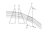
いくつかの実施形態では、第2の光学素子46と第3の光学素子47が回転する過程において、第2の光学素子46の位相角度と第3の光学素子47の位相角度の和が一定値付近で浮動し、浮動範囲は20度を超えない。ここで、位相角度とは、光屈折素子のゼロ位相と基準方向との間の夾角をいう。図18および図19に示すように、前記第2の光学素子46および第3の光学素子47の光軸の方向に沿って、基準方向は、方向Xによって表すことができ、第2の光学素子46のゼロ位相は、μ1によって表すことができ、第3の光学素子47のゼロ位相は、μ2によって表すことができ、第2の光学素子46の位相角度は、θ1によって表すことができ、第3の光学素子47の位相角度は、θ2によって表すことができ、第2の光学素子46の位相角度と第3の光学素子47の位相角度の和は、θ1+θ2によって表すことができる。ここで、位相角度の基準方向に形成される反時計回りの方向を正とし、時計回り方向を負とするか、または位相角度の基準方向に形成される時計回り方向を負とするか、反時計回り方向を正とする。 In some embodiments, in the process of rotation of the second optical element 46 and the third optical element 47, the sum of the phase angle of the second optical element 46 and the phase angle of the third optical element 47 is a constant value. It floats nearby, and the floating range does not exceed 20 degrees. Here, the phase angle refers to the included angle between the zero phase of the light refractive element and the reference direction. As shown in FIGS. 18 and 19, along the direction of the optical axis of the second optical element 46 and the third optical element 47, the reference direction can be represented by the direction The zero phase of 46 can be represented by μ1, the zero phase of the third optical element 47 can be represented by μ2, the phase angle of the second optical element 46 can be represented by θ1, and the zero phase of the third optical element 47 can be represented by θ1, The phase angle of the third optical element 47 can be expressed as θ2, and the sum of the phase angle of the second optical element 46 and the phase angle of the third optical element 47 can be expressed as θ1+θ2. Here, whether the counterclockwise direction formed in the reference direction of the phase angle is positive and the clockwise direction is negative, or the clockwise direction formed in the reference direction of the phase angle is negative, or vice versa. The clockwise direction is positive.

1つの例では、第2の光学素子46と第3の光学素子47が回転する過程において、第2の光学素子46の位相角度と第3の光学素子47の位相角度の和は一定値である。別の例では、上述した基準方向が水平方向であり、第2の光学素子46の位相角度と第3の光学素子47の位相角度の和は0度付近で浮動し、走査モジュール40で水平方向に延在する帯状の視野を走査することができ、測距装置がいくつかの場面にさらに適するようにすることができ、例えば、自動運転車の障害物回避にさらに適するようにすることができる。 In one example, in the process of rotation of the second optical element 46 and the third optical element 47, the sum of the phase angle of the second optical element 46 and the phase angle of the third optical element 47 is a constant value. . In another example, the reference direction mentioned above is the horizontal direction, the sum of the phase angle of the second optical element 46 and the phase angle of the third optical element 47 floats around 0 degrees, and the scanning module 40 moves horizontally. can scan a strip-shaped field of view extending over .

図9および図10に示すように、本実施例では、第2のロータ4331の径方向寸法が第1のロータ4231の径方向寸法よりも小さい。第2のロータ4331と第1のロータ4231は、同軸に設けられ、すなわち、第2の回転軸4337と第1の回転軸4236が重なり合う。第2のロータアセンブリ433と第1のロータアセンブリ423は、同じ回転軸の方向に沿って分布し、第2のロータアセンブリ433は、第1のロータアセンブリ423における第1の光学素子45の第1の面453を向いた位置にある。 As shown in FIGS. 9 and 10, in this embodiment, the radial dimension of the second rotor 4331 is smaller than the radial dimension of the first rotor 4231. The second rotor 4331 and the first rotor 4231 are provided coaxially, that is, the second rotation axis 4337 and the first rotation axis 4236 overlap. The second rotor assembly 433 and the first rotor assembly 423 are distributed along the direction of the same axis of rotation, and the second rotor assembly 433 is the first It is in a position facing the surface 453 of.

第3のロータ4431の径方向寸法は、第2のロータ4331の径方向寸法と等しく、第3のロータ4431の軸方向寸法は、第2のロータ4331の軸方向寸法よりも小さくても、等しくても、大きくてもよい。第3のロータ4431と第2のロータ4331は、同軸に設けられ、すなわち、第3の回転軸4437、第2の回転軸4337および第1の回転軸4236が重なり合う。第3のロータアセンブリ443と第2のロータアセンブリ433は、同じ回転軸の方向に沿って分布し、第3のロータアセンブリ443は、第2のロータアセンブリ433における第2の光学素子46の第2の面464を向いた位置にある。 The radial dimension of the third rotor 4431 is equal to the radial dimension of the second rotor 4331, and the axial dimension of the third rotor 4431 is equal to or smaller than the axial dimension of the second rotor 4331. It can also be large. The third rotor 4431 and the second rotor 4331 are provided coaxially, that is, the third rotary shaft 4437, the second rotary shaft 4337, and the first rotary shaft 4236 overlap. The third rotor assembly 443 and the second rotor assembly 433 are distributed along the direction of the same axis of rotation, and the third rotor assembly 443 is the second It is in a position facing the surface 464 of.

図9および図10に示すように、本願の実施形態では、第1の光学素子45に、背を向け合った第1の面453および第2の面454が形成される。第1の面453は、第1の回転軸4236に対して傾斜し、すなわち、第1の面453と第1の回転軸4236の夾角は0度または90度を呈さず、第2の面454は第1の回転軸4236と垂直であり、すなわち、第2の面454と第1の回転軸4236の夾角は90度を呈する。 As shown in FIGS. 9 and 10, in the embodiment of the present application, the first optical element 45 is formed with a first surface 453 and a second surface 454 facing away from each other. The first surface 453 is inclined with respect to the first rotation axis 4236, that is, the included angle between the first surface 453 and the first rotation axis 4236 is not 0 degrees or 90 degrees, and the second surface 454 is perpendicular to the first rotation axis 4236, that is, the included angle between the second surface 454 and the first rotation axis 4236 is 90 degrees.

第1の面453と第2の面454は平行でなく、第1の光学素子45の厚みは均等でなく、すなわち、第1の光学素子45の厚みはどこも同じではなく、厚みが大きい位置および厚みが小さい位置が存在すると理解することができる。1つの例では、第1の光学素子45は、第1の端451と、第2の端452と、を含み、第1の端451と第2の端452は、それぞれ第1の光学素子45の径方向における両端に位置する。第1の光学素子45の厚みは1つの方向に沿って徐々に大きくなり、第1の端451の厚みは、第2の端452の厚みよりも大きいか、または、第1の光学素子45は、ウェッジプリズム(楔形プリズム)であってもよい。 The first surface 453 and the second surface 454 are not parallel, and the thickness of the first optical element 45 is not uniform, that is, the thickness of the first optical element 45 is not the same everywhere, and there are It can be understood that there are positions where the thickness is small. In one example, the first optical element 45 includes a first end 451 and a second end 452, and the first end 451 and the second end 452 are each connected to the first optical element 45. located at both ends in the radial direction. The thickness of the first optical element 45 gradually increases along one direction, and the thickness of the first end 451 is greater than the thickness of the second end 452, or the first optical element 45 is , or a wedge prism.

各光学素子自体の重量分布が不均等であるため、高速回転時に揺動しやすくなり、十分に安定せず、回転の速度が制限される。この技術的課題を解決するため、本願の実施例のいくつかの実現形態では、走査モジュール40の重量を低下させる方式、および走査モジュール40の重量を増加させる方式により、走査モジュール40の動バランスを改善する。 Since the weight distribution of each optical element itself is uneven, it tends to swing during high-speed rotation, is not sufficiently stable, and limits the speed of rotation. To solve this technical problem, some implementations of the embodiments of the present application improve the dynamic balance of the scanning module 40 by reducing the weight of the scanning module 40 and increasing the weight of the scanning module 40. Improve.

例えば、走査モジュール40の重量を低下させる方式を採用して走査モジュール40の動バランスを改善する場合、以下のいくつかの実施例において、第1の光学素子45および第1のロータ4231のうちの少なくとも1つに切り欠きを形成する方式により、走査モジュール40の動バランスを改善する。 For example, when a method of reducing the weight of the scanning module 40 is adopted to improve the dynamic balance of the scanning module 40, in some embodiments below, the weight of the first optical element 45 and the first rotor 4231 may be reduced. The method of forming at least one notch improves the dynamic balance of the scanning module 40.

次に、第1の光学素子45と第1のロータ4231の切り欠きの位置について説明する。 Next, the positions of the first optical element 45 and the notches of the first rotor 4231 will be explained.

図9および図10に示すように、1つの例では、切り欠きは、第1の光学素子45上に設けられた隅切り455を含み、隅切り455は、第1の端451の縁に位置し、隅切り455と第1のロータ4231の第1の側壁4234の内面は、対向し、第1の光学素子45の第1の光学素子45の光路とは反対側の位置にあるか、または、隅切り455は、第1の光学素子45において光線が通らない位置にある。このようにして、隅切り455によって走査モジュール40の動バランスを改善した場合も、第1の光学素子45におけるレーザーの伝送に影響を及ぼさない。 As shown in FIGS. 9 and 10, in one example, the cutout includes a corner cutout 455 provided on the first optical element 45, with the corner cutout 455 located at the edge of the first end 451. However, the corner cutout 455 and the inner surface of the first side wall 4234 of the first rotor 4231 face each other and are located at a position opposite to the optical path of the first optical element 45 of the first optical element 45, or , the corner cut 455 is located at a position in the first optical element 45 through which the light rays do not pass. In this way, even if the dynamic balance of the scanning module 40 is improved by the corner cut 455, the transmission of the laser in the first optical element 45 is not affected.

図9および図10に示すように、1つの例では、第1の光学素子45は、第1の領域と、第2の領域と、を含む。第1の領域と第2の光学素子46は対向し、第2の領域は、第1の領域から第2の光学素子46の周縁の外まで延在する。切り欠きは、第1の光学素子45の第2の領域上に設けられた、第1の端に近い側の隅切り455を含む。 As shown in FIGS. 9 and 10, in one example, the first optical element 45 includes a first region and a second region. The first region and the second optical element 46 face each other, and the second region extends from the first region to outside the periphery of the second optical element 46 . The cutout includes a corner cutout 455 provided on the second region of the first optical element 45 near the first end.

図9および図10に示すように、1つの例では、第1のロータ4231は、第1のロータ4231の第1の回転軸4236方向に沿って分布する第3の端4237aおよび第4の端4237bを含み、第3の端4237aと第4の端4237bは、背を向け合って設けられ、第1のロータ4231の第3の端4237aは、第1の光学素子45の第2の面454に近く、第1のロータ4231の第4の端4237bは、第1の光学素子45の第1の面453に近い。切り欠きは、第1のロータ4231の第1の側壁4234の内面上に形成された内接溝4234aを含み、内接溝4234aは、第1の光学素子45の第1の端451側に近く、内接溝4234aは、第3の端4237aよりも第4の端4237b側にあるか、または、内接溝4234aは、第3の端4237aから第4の端4237bの方向に向けて延在する。別の例では、内接溝4234aと隅切り455は対向し、内接溝4234aの第1の回転軸4236における投影範囲は、隅切り455の第1の回転軸4236における投影範囲を覆う。別の例では、内接溝4234aの数は複数(2個以上)であってもよく、複数の内接溝4234aは、間隔をあけて設けられる。このようにして、面積が大きい単一の内接溝4234aが第1の側壁4234の強度に対して大きな影響を及ぼすことを回避することができる。 As shown in FIGS. 9 and 10, in one example, the first rotor 4231 has a third end 4237a and a fourth end distributed along the first rotation axis 4236 direction of the first rotor 4231. 4237b, the third end 4237a and the fourth end 4237b are provided facing each other, and the third end 4237a of the first rotor 4231 is connected to the second surface 454 of the first optical element 45. , and the fourth end 4237b of the first rotor 4231 is close to the first surface 453 of the first optical element 45. The notch includes an inscribed groove 4234a formed on the inner surface of the first side wall 4234 of the first rotor 4231, and the inscribed groove 4234a is located near the first end 451 side of the first optical element 45. , the inscribed groove 4234a is closer to the fourth end 4237b than the third end 4237a, or the inscribed groove 4234a extends from the third end 4237a toward the fourth end 4237b. do. In another example, the inscribed groove 4234a and the corner cut 455 face each other, and the projected range of the inscribed groove 4234a on the first rotation axis 4236 covers the projected range of the corner cut 455 on the first rotation axis 4236. In another example, the number of inscribed grooves 4234a may be plural (two or more), and the plurality of inscribed grooves 4234a are provided at intervals. In this way, it is possible to prevent the single inscribed groove 4234a having a large area from having a large effect on the strength of the first side wall 4234.

図9および図13に示すように、1つの例では、第1のロータ4231は、第1のロータ4231の第1の回転軸4236方向に沿って分布する第3の端4237aおよび第4の端4237bを含み、第3の端4237aと第4の端4237bは、背を向け合って設けられ、第1のロータ4231の第3の端4237aは、第1の光学素子45の第2の面454に近く、第1のロータ4231の第4の端4237bは、第1の光学素子45の第1の面453に近い。切り欠きは、第1のロータ4231の第1の側壁4234の中央(外面と内面との間)に形成された溝4234cを含み、すなわち、溝4234cは、第1の側壁4234の内面と外面を貫通しない。溝4234cは、第1の光学素子45の第1の端451側に近く、溝4234cは、第3の端4237aよりも第4の端4237b側にあるか、または、溝4234cは、第3の端4237aから第4の端4237bの方向に向けて延在する。別の例では、溝4234cの数は複数(2個以上)であってもよく、複数の溝4234cは、間隔をあけて設けられる。このようにして、面積が大きい単一の溝4234cが第1の側壁4234の強度に対して大きな影響を及ぼすことを回避することができる。 As shown in FIGS. 9 and 13, in one example, the first rotor 4231 has a third end 4237a and a fourth end distributed along the first rotation axis 4236 direction of the first rotor 4231. 4237b, the third end 4237a and the fourth end 4237b are provided facing each other, and the third end 4237a of the first rotor 4231 is connected to the second surface 454 of the first optical element 45. , and the fourth end 4237b of the first rotor 4231 is close to the first surface 453 of the first optical element 45. The cutout includes a groove 4234c formed in the center (between the outer surface and the inner surface) of the first side wall 4234 of the first rotor 4231. Does not penetrate. The groove 4234c is closer to the first end 451 side of the first optical element 45, and the groove 4234c is closer to the fourth end 4237b than the third end 4237a; It extends from the end 4237a toward the fourth end 4237b. In another example, the number of grooves 4234c may be plural (two or more), and the plurality of grooves 4234c are provided at intervals. In this way, it is possible to prevent the single groove 4234c having a large area from having a large effect on the strength of the first side wall 4234.

図9および図13に示すように、1つの例では、溝4234cの第1の回転軸4236における投影範囲は、隅切りの第1の回転軸4236における投影範囲を覆う。別の例では、溝4234cの第1の回転軸4236における投影範囲は、内接溝4234aの第1の回転軸4236における投影範囲を覆う。別の例では、溝4234cの第1の回転軸4236における投影範囲は、隅切りおよび内接溝4234aの第1の回転軸4236における投影範囲をいずれも覆う。 As shown in FIGS. 9 and 13, in one example, the projection range of the groove 4234c at the first rotation axis 4236 covers the projection range of the corner cut at the first rotation axis 4236. In another example, the projection range of the groove 4234c at the first rotation axis 4236 covers the projection range of the inscribed groove 4234a at the first rotation axis 4236. In another example, the projection range of the groove 4234c at the first rotation axis 4236 covers both the projection range of the corner cut and inscribed groove 4234a at the first rotation axis 4236.

1つの例では、第1のロータ4231は、第1のロータ4231の第1の回転軸4236方向に沿って分布する第3の端4237aおよび第4の端4237bを含み、第3の端4237aと第4の端4237bは、背を向け合って設けられ、第1のロータ4231の第3の端4237aは、第1の光学素子45の第2の面454に近く、第1のロータ4231の第4の端4237bは、第1の光学素子45の第1の面453に近い。切り欠きは、第1のロータ4231の第1の側壁4234の外面上に形成された外接溝4234bを含み、外接溝4234bは、第1の光学素子45の第1の端451側に近く、外接溝4234bは、第4の端4237bよりも第3の端4237a側にあるか、または、外接溝4234bは、第4の端4237bから第3の端4237aの方向に向けて延在する。別の例では、外接溝4234bの数は複数(2個以上)であってもよく、複数の外接溝4234bは、間隔をあけて設けられる。このようにして、面積が大きい単一の外接溝4234bが第1の側壁4234の強度に対して大きな影響を及ぼすことを回避することができる。 In one example, the first rotor 4231 includes a third end 4237a and a fourth end 4237b distributed along the first rotation axis 4236 direction of the first rotor 4231, and the third end 4237a and The fourth ends 4237b are provided facing each other, and the third end 4237a of the first rotor 4231 is close to the second surface 454 of the first optical element 45. 4 end 4237b is close to the first surface 453 of the first optical element 45. The notch includes a circumscribed groove 4234b formed on the outer surface of the first side wall 4234 of the first rotor 4231, and the circumscribed groove 4234b is close to the first end 451 side of the first optical element 45 and is not circumscribed. The groove 4234b is closer to the third end 4237a than the fourth end 4237b, or the circumscribed groove 4234b extends from the fourth end 4237b toward the third end 4237a. In another example, the number of circumscribed grooves 4234b may be plural (two or more), and the plurality of circumscribed grooves 4234b are provided at intervals. In this way, it is possible to prevent the single circumscribed groove 4234b having a large area from having a large effect on the strength of the first side wall 4234.

図10、図15および図16に示すように、1つの例では、第1のロータ4231は、第1のロータ4231の第1の回転軸4236方向に沿って分布する第3の端4237aおよび第4の端4237bを含み、第3の端4237aと第4の端4237bは、背を向け合って設けられ、第1のロータ4231の第3の端4237aは、第1の光学素子45の第2の面454に近く、第1のロータ4231の第4の端4237bは、第1の光学素子45の第1の面453に近い。第1のロータ4231の第1の側壁4234の外面上に、径方向に沿って外向きに延在してリブ4238が形成され、リブ4238は、第1のロータ4231の第1の側壁4234の周りに設けられ、リブ4238は、第3の端4237aよりも第4の端4237b側にある。切り欠きは、リブ4238上に設けられた開口4238aを含み、開口4238aは、第1の光学素子45の第1の端451側に近い。別の例では、開口4238aの数は複数(2個以上)であってもよく、複数の開口4238aは、間隔をあけて設けられる。このようにして、面積が大きい単一の開口4238aがリブ4238の強度に対して大きな影響を及ぼすことを回避することができる。 As shown in FIGS. 10, 15, and 16, in one example, the first rotor 4231 has a third end 4237a and a third end 4237a distributed along the first rotation axis 4236 direction of the first rotor 4231. The third end 4237a and the fourth end 4237b are provided facing each other, and the third end 4237a of the first rotor 4231 is connected to the second end 4237b of the first optical element 45. The fourth end 4237b of the first rotor 4231 is close to the first surface 453 of the first optical element 45. A rib 4238 is formed on the outer surface of the first side wall 4234 of the first rotor 4231 and extends radially outward. The rib 4238 is located closer to the fourth end 4237b than the third end 4237a. The cutout includes an opening 4238a provided on the rib 4238, and the opening 4238a is close to the first end 451 side of the first optical element 45. In another example, the number of openings 4238a may be plural (two or more), and the plurality of openings 4238a are provided at intervals. In this way, a single opening 4238a having a large area can be prevented from having a large effect on the strength of the rib 4238.

1つの例では、切り欠き(隅切り455、内接溝4234a、外接溝4234b、溝4234cおよび開口4238a)は、第3の補助面に関して対称であってもよく、第3の補助面は、第1の回転軸4236、第1の端および第2の端を通る平面である。 In one example, the cutouts (corner cut 455, inscribed groove 4234a, circumscribed groove 4234b, groove 4234c and opening 4238a) may be symmetrical with respect to the third auxiliary surface, and the third auxiliary surface may be symmetrical with respect to the third auxiliary surface. 1 rotation axis 4236, a plane passing through the first end and the second end.

このようにして、上記切り欠きの設置は、第1の光学素子45回転時に、厚みが不均等なために引き起こされる揺動を低下させるのに有利であり、第1のロータアセンブリ423全体を回転時にさらに安定させるのに有利である。 In this way, the installation of the notch is advantageous in reducing the rocking caused by the uneven thickness when the first optical element 45 is rotated, and the entire first rotor assembly 423 is rotated. This is sometimes advantageous for further stabilization.

図20に示すように、上記切り欠きの位置は、光路が通らない位置であり、光束の伝播に影響を及ぼさず、光学素子の出光および受光効率を低下させないと理解することができる。 As shown in FIG. 20, the position of the notch is a position through which the optical path does not pass, and it can be understood that it does not affect the propagation of the light beam and does not reduce the light output and light reception efficiency of the optical element.

走査モジュール40の重量を増加させる方式を採用して走査モジュール40の動バランスを改善する場合、以下のいくつかの実施例において、第1のロータ4231にバンプ4232を追加する方式により、走査モジュール40の動バランスを改善する。 When increasing the weight of the scanning module 40 to improve the dynamic balance of the scanning module 40, in some embodiments below, the scanning module 40 may be increased by adding a bump 4232 to the first rotor 4231. Improves dynamic balance.

図9および図10に示すように、次に、第1のロータ4231とバンプ4232の位置について説明する。 Next, as shown in FIGS. 9 and 10, the positions of the first rotor 4231 and the bumps 4232 will be described.

第1のロータアセンブリ423は、バンプ4232をさらに含み、バンプ4232は、第1のロータアセンブリ423回転時の動安定を高めるために用いられる。具体的には、バンプ4232は、第1のロータ4231の第1の側壁4234上に設けられ、第1の収納キャビティ4235内に位置し、バンプ4232は、第1の側壁4234から第1の収納キャビティ4235の中心に向けて延在し、バンプ4232が第1の収納キャビティ4235の中心に向けて延在する高さは、第1の収納キャビティ4235の径方向幅の所定の割合よりも低くてもよく、所定の割合は、0.1、0.22、0.3、0.33などであってもよく、バンプ4232が第1の収納キャビティ4235を多く遮りすぎレーザーパルスの伝送光路に影響を及ぼすことを回避する。 The first rotor assembly 423 further includes a bump 4232, and the bump 4232 is used to increase dynamic stability when the first rotor assembly 423 rotates. Specifically, the bump 4232 is provided on the first side wall 4234 of the first rotor 4231 and is located within the first storage cavity 4235, and the bump 4232 is connected from the first side wall 4234 to the first storage cavity 4235. The height at which the bump 4232 extends toward the center of the first storage cavity 4235 is less than a predetermined percentage of the radial width of the first storage cavity 4235. Alternatively, the predetermined ratio may be 0.1, 0.22, 0.3, 0.33, etc., such that the bump 4232 blocks too much of the first storage cavity 4235 and affects the transmission optical path of the laser pulse. avoid causing harm.

バンプ4232は、第1のロータ4231に固定接続されてもよく、これにより、バンプ4232が第1のロータ4231と同期回転することを実現する。バンプ4232は、第1のロータ4231と一体成形してもよく、例えば、射出成形などの工程によって一体成形する。バンプ4232は、第1のロータ4231と別々に成形してもよく、バンプ4232と第1のロータ4231をそれぞれ成形した後、接着剤でバンプ4232を第1の側壁4234上に粘着するなど、バンプ4232を第1のロータ4231の第1の側壁4234上に固定し、またはバンプ4232を例えばネジなどの締結部材で第1のロータ4231の第1の側壁4234上に固定する。ここで、バンプ4232の第1の側壁4234と貼着する面は、曲面である。本願の実施形態では、バンプ4232は第1のヨーク4233aと同期回転し、バンプ4232は第1のヨーク4233aに固定接続される。 The bumps 4232 may be fixedly connected to the first rotor 4231, thereby achieving synchronous rotation of the bumps 4232 with the first rotor 4231. The bumps 4232 may be integrally molded with the first rotor 4231, for example, by a process such as injection molding. The bump 4232 may be molded separately from the first rotor 4231, and after the bump 4232 and the first rotor 4231 are molded, the bump 4232 may be adhered onto the first side wall 4234 with an adhesive. 4232 is fixed on the first side wall 4234 of the first rotor 4231, or the bump 4232 is fixed on the first side wall 4234 of the first rotor 4231 with a fastening member such as a screw. Here, the surface of the bump 4232 that is attached to the first side wall 4234 is a curved surface. In embodiments of the present application, the bump 4232 rotates synchronously with the first yoke 4233a, and the bump 4232 is fixedly connected to the first yoke 4233a.

図10および図11に示すように、1つの例では、バンプ4232を第1の収納キャビティ4235内に取り付ける際に、バンプ4232と第1の光学素子45は、第1のロータ4231の径方向に沿って分布する。このとき、第1の光学素子45の第1の端451は、第1の側壁4234の内面と接触してもよく、第2の端452と第1の側壁4234は間隙を形成し、バンプ4232がこの間隙内に入る。このようにして、第2の端452とバンプ4232は、第1の回転軸4236の同じ側に位置し、第1の端451とバンプ4232は、第1の回転軸4236の対向する両側に位置し、第1の光学素子45と第1のロータアセンブリ423が共同で回転する際に、第1の光学素子45とバンプ4232が形成する全体的な回転が安定し、これにより、第1のロータアセンブリ423に揺動が生じることを回避し、第1のロータアセンブリ423全体が回転する際にさらに安定するのに有利である。別の例では、バンプ4232と第1の光学素子45は間隔をあけ、バンプ4232の第1の光学素子45を向いた面は平面である。別の例では、バンプ4232の第1の回転軸4236における投影範囲は、第1の光学素子45の第1の回転軸4236における投影範囲を覆う。 As shown in FIGS. 10 and 11, in one example, when bump 4232 is installed within first storage cavity 4235, bump 4232 and first optical element 45 are radially aligned with first rotor 4231. distributed along. At this time, the first end 451 of the first optical element 45 may contact the inner surface of the first side wall 4234, the second end 452 and the first side wall 4234 form a gap, and the bump 4232 enters this gap. In this way, the second end 452 and the bump 4232 are located on the same side of the first axis of rotation 4236, and the first end 451 and the bump 4232 are located on opposite sides of the first axis of rotation 4236. However, when the first optical element 45 and the first rotor assembly 423 jointly rotate, the overall rotation formed by the first optical element 45 and the bump 4232 is stabilized, so that the first rotor It is advantageous to avoid rocking in the assembly 423 and to make the entire first rotor assembly 423 more stable when rotating. In another example, bump 4232 and first optical element 45 are spaced apart, and the surface of bump 4232 facing first optical element 45 is flat. In another example, the projection range of the bump 4232 at the first rotation axis 4236 covers the projection range of the first optical element 45 at the first rotation axis 4236.

図14に示すように、1つの例では、バンプ4232を第1の収納キャビティ4235内に取り付ける際に、バンプ4232と第1の光学素子45は、第1のロータ4231の第1の回転軸4236方向に沿って並列に設けられる。このとき、第1の光学素子45の第1の端451および第2の端452は、いずれも第1の側壁4234の内面と接触してもよく、バンプ4232をできる限り第1の光学素子45に近づけるため、バンプ4232は、第1の光学素子45と接触してもよい。具体的には、バンプ4232は、第1の光学素子45の第1の面453が所在する側に位置し、バンプ4232は、第1の光学素子45の第1の面453に当接してもよい。第1の光学素子45を取り付ける際に、第1の面453がバンプ4232に当接すると、第1の光学素子45が第1の収納キャビティ4235の深さ方向にしっかり取り付けられたと考えることができる。さらに具体的には、バンプ4232は、バンプ側壁1232aを含み、バンプ側壁1232aは、第1の面453に当接する。別の例では、第1の光学素子45の第1の回転軸4236における投影範囲は、バンプ4232の第1の回転軸4236における投影範囲を覆う。 As shown in FIG. 14, in one example, when installing the bump 4232 into the first storage cavity 4235, the bump 4232 and the first optical element 45 are connected to the first axis of rotation 4236 of the first rotor 4231. are provided in parallel along the direction. At this time, both the first end 451 and the second end 452 of the first optical element 45 may be in contact with the inner surface of the first side wall 4234, and the bump 4232 is as close to the first optical element 45 as possible. The bump 4232 may be in contact with the first optical element 45 to bring it closer to the first optical element 45 . Specifically, the bump 4232 is located on the side where the first surface 453 of the first optical element 45 is located, and even if the bump 4232 comes into contact with the first surface 453 of the first optical element 45, good. When the first surface 453 comes into contact with the bump 4232 when attaching the first optical element 45, it can be considered that the first optical element 45 is firmly attached in the depth direction of the first storage cavity 4235. . More specifically, bump 4232 includes bump sidewall 1232a, and bump sidewall 1232a abuts first surface 453. In another example, the projection range of the first optical element 45 at the first rotation axis 4236 covers the projection range of the bump 4232 at the first rotation axis 4236.

1つの例では、バンプ4232を第1の収納キャビティ4235内に取り付ける際に、バンプ4232と第1の光学素子45は、第1のロータ4231の第1の回転軸4236方向に沿って並列に設けられる。このとき、第1の光学素子45の第1の端451および第2の端452は、いずれも第1の側壁4234の内面と接触してもよく、バンプ4232と第1のロータ4231を一体成形する際の工程の流れを簡素化するため、バンプ側壁1232aは、第1の回転軸4236に垂直な平板状を呈してもよく、バンプ側壁1232aは、階段状を呈してもよい。バンプ側壁1232aは、さらに、第1の回転軸4236に対して傾斜してもよく、すなわち、バンプ側壁1232aは第1の回転軸4236に垂直ではなく、別の例では、バンプ側壁1232aの傾斜方向は第1の面453の方向と同じであり、バンプ側壁1232aは第1の面453に貼着され、バンプ4232の釣り合い作用を最大限に発揮できるよう、バンプ側壁1232aと第1の面453をできる限り近づけ、バンプ4232の高さを小さくすることにより、バンプ4232による光路の遮りを小さくする。別の例では、第1の光学素子45の第1の回転軸4236における投影範囲は、バンプ4232の第1の回転軸4236における投影範囲を覆う。 In one example, when the bump 4232 is installed in the first storage cavity 4235, the bump 4232 and the first optical element 45 are provided in parallel along the direction of the first rotation axis 4236 of the first rotor 4231. It will be done. At this time, the first end 451 and the second end 452 of the first optical element 45 may both contact the inner surface of the first side wall 4234, and the bump 4232 and the first rotor 4231 may be integrally molded. In order to simplify the flow of the process, the bump side wall 1232a may have a flat plate shape perpendicular to the first rotation axis 4236, and the bump side wall 1232a may have a stepped shape. The bump sidewall 1232a may further be inclined with respect to the first axis of rotation 4236, i.e., the bump sidewall 1232a is not perpendicular to the first axis of rotation 4236, and in another example, the direction of inclination of the bump sidewall 1232a is the same as the direction of the first surface 453, the bump side wall 1232a is attached to the first surface 453, and the bump side wall 1232a and the first surface 453 are aligned to maximize the balancing effect of the bump 4232. By making the bumps 4232 as close as possible and reducing the height of the bumps 4232, the interruption of the optical path by the bumps 4232 is reduced. In another example, the projection range of the first optical element 45 at the first rotation axis 4236 covers the projection range of the bump 4232 at the first rotation axis 4236.

1つの例では、バンプ4232は、釣り合いの作用を奏することができ、バンプ4232は第1の光学素子45と同期回転し、バンプ4232が第2の端452と共同で回転する際の第1の回転軸4236に対するトルクは、第1の端451が回転する際の第1の回転軸4236に対するトルクと等しく、つまり、バンプ4232が第2の端452と共同で回転する際に生じるトルクは、いずれも第1の光学素子45の第1の端451が回転する際に生じるトルクと相殺され、第1のロータ4231の他の位置が回転する際の安定性に影響を及ぼさない。 In one example, the bump 4232 can act as a counterbalance, such that the bump 4232 rotates synchronously with the first optical element 45 such that the bump 4232 rotates synchronously with the first optical element 45 . The torque on the rotation axis 4236 is equal to the torque on the first rotation axis 4236 when the first end 451 rotates, that is, the torque produced when the bump 4232 jointly rotates with the second end 452 is This also cancels out the torque generated when the first end 451 of the first optical element 45 rotates, and does not affect the stability when other positions of the first rotor 4231 rotate.

1つの例では、バンプ4232は、第3の補助面に関して対称であり、第3の補助面は、第1の回転軸4236、第1の端451および第2の端452を通る平面である。別の例では、バンプ4232は、さらに、第1の補助面に関して対称であり、第1の補助面は、第1の回転軸4236に垂直で、第1の面453の中心を通る平面である。このようにして、バンプ4232は、さらに良好に第1の光学素子45と重量の調整を行うことができる。 In one example, bump 4232 is symmetrical about a third auxiliary surface, which is a plane passing through first axis of rotation 4236, first end 451, and second end 452. In another example, the bump 4232 is further symmetrical with respect to a first auxiliary surface, the first auxiliary surface being a plane perpendicular to the first axis of rotation 4236 and passing through the center of the first surface 453. . In this way, the bump 4232 can achieve better weight adjustment with the first optical element 45.

1つの例では、バンプ4232の密度は、第1のロータ4231の密度よりも大きく、バンプ4232を第1の収納キャビティ4235内に設ける際に、同じ質量を保証し、すなわち、同じ釣り合い作用の下で、バンプ4232の体積を小さく設けることができ、バンプ4232による第1の収納キャビティ4235を通るレーザーパルスに対する影響を少なくする。別の例では、バンプ4232の密度は、さらに、同じバンプ4232の体積でできる限り小さく設計することができるよう、第1の光学素子45の密度よりも大きくてもよい。 In one example, the density of the bumps 4232 is greater than the density of the first rotor 4231 to ensure the same mass when providing the bumps 4232 within the first storage cavity 4235, i.e. under the same counterbalancing action. In this case, the volume of the bump 4232 can be small, and the influence of the bump 4232 on the laser pulse passing through the first storage cavity 4235 is reduced. In another example, the density of the bumps 4232 may also be greater than the density of the first optical element 45 so that the same bump 4232 volume can be designed as small as possible.

このようにして、上記バンプ4232の設置は、第1の光学素子45回転時に、厚みが不均等なために引き起こされる揺動を低下させるのに有利であり、第1のロータアセンブリ423全体を回転時にさらに安定させるのに有利である。 In this way, the installation of the bump 4232 is advantageous in reducing the wobbling caused by the uneven thickness when the first optical element 45 rotates, and the entire first rotor assembly 423 rotates. This is sometimes advantageous for further stabilization.

図14に示すように、1つの例では、第1のロータ4231は、第1のロータ4231の第1の回転軸4236方向に沿って分布する第3の端4237aおよび第4の端4237bを含み、第3の端4237aと第4の端4237bは、背を向け合って設けられ、第1のロータ4231の第3の端4237aは、第1の光学素子45の第2の面454に近く、第1のロータ4231の第4の端4237bは、第1の光学素子45の第1の面453に近い。第1のロータ4231の第1の側壁4234の内面には、回避面取り4230が設けられ、回避面取り4230は、第3の端4237a側に近い。このようにして、回避面取り4230は、第1の光学素子45を第1の収納キャビティ4235内に取り付けやすくするのに有利なだけでなく、第1の光学素子45が受光して反射して戻って来るレーザーパルスの角度を増加するのにも有利である。 As shown in FIG. 14, in one example, the first rotor 4231 includes a third end 4237a and a fourth end 4237b distributed along the first rotation axis 4236 direction of the first rotor 4231. , the third end 4237a and the fourth end 4237b are provided with their backs facing each other, and the third end 4237a of the first rotor 4231 is close to the second surface 454 of the first optical element 45, The fourth end 4237b of the first rotor 4231 is close to the first surface 453 of the first optical element 45. An avoidance chamfer 4230 is provided on the inner surface of the first side wall 4234 of the first rotor 4231, and the avoidance chamfer 4230 is close to the third end 4237a side. In this way, the avoidance chamfer 4230 not only facilitates mounting the first optical element 45 within the first storage cavity 4235, but also allows the first optical element 45 to receive and reflect light back into the first optical element 45. It is also advantageous to increase the angle of the incoming laser pulse.

1つの例では、第1のロータ4231は、第1のロータ4231の第1の回転軸4236方向に沿って分布する第3の端4237aおよび第4の端4237bを含み、第3の端4237aと第4の端4237bは、背を向け合って設けられ、第1のロータ4231の第3の端4237aは、第1の光学素子45の第2の面454に近く、第1のロータ4231の第4の端4237bは、第1の光学素子45の第1の面453に近い。第1のロータ4231は、突起4234dをさらに含み、突起4234dは、第1のロータ4231の第1の側壁4234の内面上に設けられ、第3の端4237a側に近く、第1の端451は、突起4234d上に取り付けられる。 In one example, the first rotor 4231 includes a third end 4237a and a fourth end 4237b distributed along the first rotation axis 4236 direction of the first rotor 4231, and the third end 4237a and The fourth ends 4237b are provided facing each other, and the third end 4237a of the first rotor 4231 is close to the second surface 454 of the first optical element 45. 4 end 4237b is close to the first surface 453 of the first optical element 45. The first rotor 4231 further includes a protrusion 4234d, the protrusion 4234d is provided on the inner surface of the first side wall 4234 of the first rotor 4231, and is close to the third end 4237a side, and the first end 451 is , is attached on the protrusion 4234d.

1つの例では、第1の光学素子45上に増透膜がコーティングされ、増透膜の厚みは、光源から発射されるレーザーパルスの波長と等しく、レーザーパルスが第1の光学素子45を通るときの損失を低減することができる。 In one example, a transmission film is coated on the first optical element 45, the thickness of the transmission film is equal to the wavelength of the laser pulse emitted from the light source, and the laser pulse passes through the first optical element 45. It is possible to reduce the loss when

図10に示すように、本願の実施形態では、第2の光学素子46に、背を向け合った第1の面463および第2の面464が形成される。第2の光学素子46の第1の面463は、第1の光学素子45の第1の面453を向き、第2の光学素子46の第1の面463は、第2の回転軸4337に対して傾斜し、すなわち、第1の面463と第2の回転軸4337の夾角は、0度または90度を呈さない。第2の光学素子46の第2の面464と第1の光学素子45の第1の面453は、背を向け合い、第2の光学素子46の第2の面464は、第2の回転軸4337に垂直であり、すなわち、第2の面464と第2の回転軸4337の夾角は90度を呈するか、または、第2の光学素子46の第2の面464と第1の光学素子45の第2の面454は平行である。 As shown in FIG. 10, in the embodiment of the present application, the second optical element 46 is formed with a first surface 463 and a second surface 464 facing away from each other. The first surface 463 of the second optical element 46 faces the first surface 453 of the first optical element 45, and the first surface 463 of the second optical element 46 faces the second rotation axis 4337. In other words, the included angle between the first surface 463 and the second rotation axis 4337 is not 0 degrees or 90 degrees. The second surface 464 of the second optical element 46 and the first surface 453 of the first optical element 45 face each other, and the second surface 464 of the second optical element 46 perpendicular to the axis 4337, i.e. the included angle between the second surface 464 and the second axis of rotation 4337 presents 90 degrees, or the second surface 464 of the second optical element 46 and the first optical element The second faces 454 of 45 are parallel.

第2の光学素子46の第1の面463と第2の面464は平行でなく、第2の光学素子46の厚みは均等でなく、すなわち、第2の光学素子46の厚みはどこも同じではなく、厚みが大きい位置および厚みが小さい位置が存在すると理解することができる。1つの例では、第2の光学素子46は、第1の端461と、第2の端462と、を含み、第1の端461と第2の端462は、それぞれ第2の光学素子46の径方向における両端に位置する。第2の光学素子46の厚みは、1つの方向に沿って徐々に大きくなる。かつ、第1の端461の厚みは、第2の端462の厚みよりも大きいか、または、第2の光学素子46は、ウェッジプリズム(楔形プリズム)であってもよい。 The first surface 463 and the second surface 464 of the second optical element 46 are not parallel, and the thickness of the second optical element 46 is not equal, that is, the thickness of the second optical element 46 is not the same everywhere. It can be understood that there are locations where the thickness is large and locations where the thickness is small. In one example, the second optical element 46 includes a first end 461 and a second end 462, where the first end 461 and the second end 462 are each connected to the second optical element 46. located at both ends in the radial direction. The thickness of the second optical element 46 gradually increases along one direction. In addition, the thickness of the first end 461 may be greater than the thickness of the second end 462, or the second optical element 46 may be a wedge prism.

ウェッジプリズム自体の重量分布が不均等であるため、ウェッジプリズムを高速回転させるときに、走査モジュール40全体が揺動しやすくなり、十分に安定しない可能性がある。この技術的課題を解決するため、本願の実施例のいくつかの実現形態では、走査モジュール40の重量を増加する方式により、走査モジュール40の動バランスを改善する。例えば、第2のロータ4331内にボス4332を追加する方式によって、走査モジュール40の動バランスを改善することができる。 Since the weight distribution of the wedge prism itself is uneven, when the wedge prism is rotated at high speed, the entire scanning module 40 tends to swing and may not be sufficiently stable. To solve this technical problem, some implementations of the embodiments of the present application improve the dynamic balance of the scanning module 40 by increasing the weight of the scanning module 40. For example, the dynamic balance of the scanning module 40 can be improved by adding a boss 4332 within the second rotor 4331.

図10に示すように、1つの例では、第2のロータアセンブリ433は、ボス4332をさらに含み、ボス4332は、第2のロータ4331の第2の側壁4335上に設けられ、第2の収納キャビティ4336内に位置し、ボス4332は、第2のロータアセンブリ433回転時の動安定を高めるために用いられる。具体的には、ボス4332は、第2の側壁4335から第2の収納キャビティ4336の中心に向けて延在し、ボス4332が第2の収納キャビティ4336の中心に向けて延在する高さは、第2の収納キャビティ4336の径方向幅の所定の割合よりも低くてもよく、所定の割合は、0.1、0.22、0.3、0.33などであってもよく、ボス4332が第2の収納キャビティ4336を多く遮りすぎレーザーパルスの伝送光路に影響を及ぼすことを回避する。 As shown in FIG. 10, in one example, the second rotor assembly 433 further includes a boss 4332 that is provided on the second sidewall 4335 of the second rotor 4331 and that is disposed on the second side wall 4335 of the second rotor 4331. Located within cavity 4336, boss 4332 is used to increase dynamic stability during rotation of second rotor assembly 433. Specifically, the boss 4332 extends from the second sidewall 4335 toward the center of the second storage cavity 4336, and the height at which the boss 4332 extends toward the center of the second storage cavity 4336 is , may be less than a predetermined percentage of the radial width of the second storage cavity 4336, the predetermined percentage may be 0.1, 0.22, 0.3, 0.33, etc., and the boss 4332 to avoid blocking the second storage cavity 4336 too much and affecting the transmission optical path of the laser pulse.

ボス4332は、第2のロータ4331に固定接続されてもよく、これにより、ボス4332が第2のロータ4331と同期回転することを実現する。ボス4332は、第2のロータ4331と一体成形してもよく、例えば、射出成形などの工程によって一体成形する。ボス4332は、第2のロータ4331と別々に成形してもよく、ボス4332と第2のロータ4331をそれぞれ成形した後、接着剤でボス4332を第2の側壁4335上に粘着するなど、ボス4332を第2のロータ4331の第2の側壁4335上に固定し、またはボス4332を例えばネジなどの締結部材で第2のロータ4331の第2の側壁4335上に固定する。ここで、ボス4332の第2の側壁4335と貼着される面は、曲面である。本願の実施形態では、ボス4332は第2のヨーク4333と同期回転し、ボス4332は第2のヨーク4333に固定接続される。 The boss 4332 may be fixedly connected to the second rotor 4331, thereby enabling the boss 4332 to rotate synchronously with the second rotor 4331. The boss 4332 may be integrally molded with the second rotor 4331, for example, by a process such as injection molding. The boss 4332 may be molded separately from the second rotor 4331. After the boss 4332 and the second rotor 4331 are molded, the boss 4332 may be attached to the second side wall 4335 using an adhesive. 4332 is fixed on the second side wall 4335 of the second rotor 4331, or the boss 4332 is fixed on the second side wall 4335 of the second rotor 4331 with a fastening member such as a screw. Here, the surface of the boss 4332 that is attached to the second side wall 4335 is a curved surface. In embodiments of the present application, the boss 4332 rotates synchronously with the second yoke 4333, and the boss 4332 is fixedly connected to the second yoke 4333.

図10に示すように、1つの例では、ボス4332を第2の収納キャビティ4336内に取り付ける際に、ボス4332と第2の光学素子46は、第2のロータ4331の径方向に沿って分布する。このとき、第2の光学素子46の第1の端461は、第2の側壁4335の内面と接触してもよく、第2の端462と第2の側壁4335は間隙を形成し、ボス4332がこの間隙内に入る。このようにして、第2の端462とボス4332は、第2の回転軸4337の同じ側に位置し、第1の端461とボス4332は、第2の回転軸4337の対向する両側に位置し、第2の光学素子46と第2のロータアセンブリ433が共同で回転する際に、第2の光学素子46とボス4332が形成する全体的な回転が安定し、これにより、第2のロータアセンブリ433に揺動が生じることを回避し、第2のロータアセンブリ433全体が回転する際にさらに安定するのに有利である。別の例では、ボス4332と第2の光学素子46は間隔をあけ、ボス4332の第2の光学素子46を向いた面は平面である。別の例では、ボス4332の第2の回転軸4337における投影範囲は、第2の光学素子46の第2の回転軸4337における投影範囲を覆う。 As shown in FIG. 10, in one example, when installing the boss 4332 within the second storage cavity 4336, the boss 4332 and the second optical element 46 are distributed along the radial direction of the second rotor 4331. do. At this time, the first end 461 of the second optical element 46 may contact the inner surface of the second side wall 4335, the second end 462 and the second side wall 4335 form a gap, and the boss 4332 enters this gap. In this way, the second end 462 and the boss 4332 are located on the same side of the second axis of rotation 4337, and the first end 461 and the boss 4332 are located on opposite sides of the second axis of rotation 4337. However, when the second optical element 46 and the second rotor assembly 433 jointly rotate, the overall rotation formed by the second optical element 46 and the boss 4332 is stabilized, so that the second rotor It is advantageous to avoid rocking of the assembly 433 and to make the entire second rotor assembly 433 more stable when rotating. In another example, boss 4332 and second optical element 46 are spaced apart and the surface of boss 4332 facing second optical element 46 is flat. In another example, the projection range of the boss 4332 at the second rotation axis 4337 covers the projection range of the second optical element 46 at the second rotation axis 4337.

図14に示すように、1つの例では、ボス4332を第2の収納キャビティ4336内に取り付ける際に、ボス4332と第2の光学素子46は、第2のロータ4331の第2の回転軸4337方向に沿って並列に設けられる。このとき、第2の光学素子46の第1の端461および第2の端462は、いずれも第2の側壁4335の内面と接触してもよく、ボス4332をできる限り第2の光学素子46に近づけるため、ボス4332は、第2の光学素子46と接触してもよい。具体的には、ボス4332は、第2の光学素子46の第1の面463が所在する側に位置し、ボス4332は、第2の光学素子46の第1の面463に当接してもよい。第2の光学素子46を取り付ける際に、第1の面463がボス4332に当接すると、第2の光学素子46が第2の収納キャビティ4336の深さ方向にしっかり取り付けられたと考えることができる。さらに具体的には、ボス4332は、ボス側壁1332aを含み、ボス側壁1332aは、第1の面463に当接する。別の例では、第2の光学素子46の第2の回転軸4337における投影範囲は、ボス4332の第2の回転軸4337における投影範囲を覆う。 As shown in FIG. 14, in one example, when the boss 4332 is installed within the second storage cavity 4336, the boss 4332 and the second optical element 46 are connected to the second axis of rotation 4337 of the second rotor 4331. are provided in parallel along the direction. At this time, the first end 461 and the second end 462 of the second optical element 46 may both be in contact with the inner surface of the second side wall 4335, and the boss 4332 is as close to the second optical element 46 as possible. The boss 4332 may be in contact with the second optical element 46 to bring it closer to the second optical element 46 . Specifically, the boss 4332 is located on the side where the first surface 463 of the second optical element 46 is located, and even if the boss 4332 comes into contact with the first surface 463 of the second optical element 46, good. When the first surface 463 comes into contact with the boss 4332 when attaching the second optical element 46, it can be considered that the second optical element 46 is firmly attached in the depth direction of the second storage cavity 4336. . More specifically, the boss 4332 includes a boss side wall 1332a, and the boss side wall 1332a abuts the first surface 463. In another example, the projection range of the second optical element 46 at the second rotation axis 4337 covers the projection range of the boss 4332 at the second rotation axis 4337.

図14に示すように、1つの例では、ボス4332を第2の収納キャビティ4336内に取り付ける際に、ボス4332と第2の光学素子46は、第2のロータ4331の第2の回転軸4337方向に沿って並列に設けられる。このとき、第2の光学素子46の第1の端461および第2の端462は、いずれも第2の側壁4335の内面と接触してもよく、ボス4332と第2のロータ4331を一体成形する際の工程の流れを簡素化するため、ボス側壁1332aは、第2の回転軸4337と垂直な平板状を呈してもよく、ボス側壁1332aは、階段状を呈してもよい。ボス側壁1332aは、さらに、第2の回転軸4337に対して傾斜してもよく、すなわち、ボス側壁1332aは第2の回転軸4337に垂直ではなく、別の例では、ボス側壁1332aの傾斜方向は第1の面463の方向と同じであり、ボス側壁1332aは第1の面463に貼着され、ボス4332の釣り合い作用を最大限に発揮できるよう、ボス側壁1332aと第1の面463をできる限り近づけ、ボス4332の高さを小さくすることにより、ボス4332による光路の遮りを小さくする。別の例では、第2の光学素子46の第2の回転軸4337における投影範囲は、ボス4332の第2の回転軸4337における投影範囲を覆う。 As shown in FIG. 14, in one example, when the boss 4332 is installed within the second storage cavity 4336, the boss 4332 and the second optical element 46 are connected to the second axis of rotation 4337 of the second rotor 4331. are provided in parallel along the direction. At this time, the first end 461 and the second end 462 of the second optical element 46 may both contact the inner surface of the second side wall 4335, and the boss 4332 and the second rotor 4331 may be integrally molded. In order to simplify the flow of the process, the boss side wall 1332a may have a flat plate shape perpendicular to the second rotating shaft 4337, and the boss side wall 1332a may have a stepped shape. The boss sidewall 1332a may further be inclined with respect to the second axis of rotation 4337, i.e., the boss sidewall 1332a is not perpendicular to the second axis of rotation 4337, and in another example, the direction of inclination of the boss sidewall 1332a is the same as the direction of the first surface 463, the boss side wall 1332a is attached to the first surface 463, and the boss side wall 1332a and the first surface 463 are aligned to maximize the balancing effect of the boss 4332. By making the height of the boss 4332 as close as possible and reducing the height of the boss 4332, the obstruction of the optical path by the boss 4332 is reduced. In another example, the projection range of the second optical element 46 at the second rotation axis 4337 covers the projection range of the boss 4332 at the second rotation axis 4337.

1つの例では、ボス4332は、釣り合いの作用を奏することができ、ボス4332は第2の光学素子46と同期回転し、ボス4332が第2の端462と共同で回転する際の第2の回転軸4337に対するトルクは、第1の端461が回転する際の第2の回転軸4337に対するトルクと等しく、つまり、ボス4332が第2の端462と共同で回転する際に生じるトルクは、いずれも第2の光学素子46の第1の端461が回転する際に生じるトルクと相殺され、第2のロータ4331の他の位置が回転する際の安定性に影響を及ぼさない。 In one example, the boss 4332 can act as a counterbalance, such that the boss 4332 rotates synchronously with the second optical element 46 and the second The torque on the rotation axis 4337 is equal to the torque on the second rotation axis 4337 when the first end 461 rotates, that is, the torque produced when the boss 4332 rotates jointly with the second end 462 is This also cancels out the torque generated when the first end 461 of the second optical element 46 rotates, and does not affect the stability when other positions of the second rotor 4331 rotate.

1つの例では、ボス4332は、第3の補助面に関して対称であり、第3の補助面は、第2の回転軸4337、第1の端461および第2の端462を通る平面である。別の例では、ボス4332は、さらに、第1の補助面に関して対称であり、第1の補助面は、第2の回転軸4337に垂直で、第1の面463の中心を通る平面である。このようにして、ボス4332は、さらに良好に第2の光学素子46と重量の調整を行うことができる。 In one example, boss 4332 is symmetrical about a third auxiliary surface, which is a plane passing through second axis of rotation 4337, first end 461, and second end 462. In another example, the boss 4332 is further symmetrical with respect to a first auxiliary surface, the first auxiliary surface being a plane perpendicular to the second axis of rotation 4337 and passing through the center of the first surface 463. . In this way, the boss 4332 can achieve better weight adjustment with the second optical element 46.

1つの例では、ボス4332の密度は、第2のロータ4331の密度よりも大きく、ボス4332を第2の収納キャビティ4336内に設ける際に、同じ質量を保証し、すなわち、同じ釣り合い作用の下で、ボス4332の体積を小さく設けることができ、ボス4332による第2の収納キャビティ4336を通るレーザーパルスに対する影響を少なくする。別の例では、ボス4332の密度は、さらに、同じボス4332の体積でできる限り小さく設計することができるよう、第2の光学素子46の密度よりも大きくてもよい。 In one example, the density of the boss 4332 is greater than the density of the second rotor 4331 to ensure the same mass when providing the boss 4332 within the second storage cavity 4336, i.e., under the same counterbalancing action. In this case, the volume of the boss 4332 can be made small, which reduces the influence of the boss 4332 on the laser pulse passing through the second storage cavity 4336. In another example, the density of the boss 4332 may also be greater than the density of the second optical element 46 so that the same boss 4332 volume can be designed as small as possible.

このようにして、上記ボス4332の設置は、第2の光学素子46回転時に、厚みが不均等なために引き起こされる揺動を低下させるのに有利であり、第2のロータアセンブリ433全体を回転時にさらに安定させるのに有利である。 In this way, the installation of the boss 4332 is advantageous in reducing the rocking caused by the uneven thickness when the second optical element 46 rotates, and the entire second rotor assembly 433 rotates. This is sometimes advantageous for further stabilization.

図10に示すように、1つの例では、第2の光学素子46上に増透膜がコーティングされ、増透膜の厚みは、光源から発射されるレーザーパルスの波長と等しく、レーザーパルスが第2の光学素子46を通るときの損失を低減することができる。 As shown in FIG. 10, in one example, a transmission film is coated on the second optical element 46, and the thickness of the transmission film is equal to the wavelength of the laser pulse emitted from the light source, such that the laser pulse is The loss when passing through the second optical element 46 can be reduced.

1つの例では、第2の光学素子46の口径の大きさは、第1の光学素子45の口径の大きさの50%~70%である。例えば、2つの光学素子(第1の光学素子45および第2の光学素子46)の口径の大きさの差は、50%であってもよく、2つの光学素子(第1の光学素子45および第2の光学素子46)の口径の大きさの差は、60%であってもよい。このようにして、2つの光学素子(第1の光学素子45および第2の光学素子46)の口径寸法は、適切な範囲内において光線の伝播に有利である。 In one example, the aperture size of the second optical element 46 is between 50% and 70% of the aperture size of the first optical element 45. For example, the difference in aperture size between the two optical elements (the first optical element 45 and the second optical element 46) may be 50%. The difference in the aperture size of the second optical element 46) may be 60%. In this way, the aperture dimensions of the two optical elements (first optical element 45 and second optical element 46) are favorable for the propagation of the light rays within a suitable range.

図10に示すように、本願の実施形態では、第3の光学素子47に、背を向け合った第1の面473および第2の面474が形成される。第3の光学素子47の第1の面473と第2の光学素子46の第2の面464は、背を向け合い、第3の光学素子47の第1の面473は、第3の回転軸4437に対して傾斜し、すなわち、第1の面473と第3の回転軸4437の夾角は、0度または90度を呈さない。第3の光学素子47の第2の面474と第2の光学素子46の第2の面464は、対向し、第3の光学素子47の第2の面474は、第3の回転軸4437に垂直であり、すなわち、第2の面474と第3の回転軸4437の夾角は90度を呈するか、または、第3の光学素子47の第2の面474と第2の光学素子46の第2の面464は平行であるか、または、第3の光学素子47の第2の面474、第2の光学素子46の第2の面464および第1の光学素子45の第2の面454の三者は、互いに平行である。 As shown in FIG. 10, in the embodiment of the present application, the third optical element 47 is formed with a first surface 473 and a second surface 474 facing away from each other. The first surface 473 of the third optical element 47 and the second surface 464 of the second optical element 46 face each other, and the first surface 473 of the third optical element 47 It is inclined with respect to the axis 4437, that is, the included angle between the first surface 473 and the third rotation axis 4437 does not exhibit 0 degrees or 90 degrees. The second surface 474 of the third optical element 47 and the second surface 464 of the second optical element 46 face each other, and the second surface 474 of the third optical element 47 faces the third rotation axis 4437. , that is, the included angle between the second surface 474 and the third rotation axis 4437 is 90 degrees, or the angle between the second surface 474 of the third optical element 47 and the second optical element 46 is 90 degrees. The second surface 464 is parallel, or the second surface 474 of the third optical element 47 , the second surface 464 of the second optical element 46 and the second surface of the first optical element 45 454 are parallel to each other.

第3の光学素子47の第1の面473と第2の面474は平行でなく、第3の光学素子47の厚みは均等でなく、すなわち、第3の光学素子47の厚みはどこも同じではなく、厚みが大きい位置および厚みが小さい位置が存在すると理解することができる。1つの例では、第3の光学素子47は、第1の端471と、第2の端472と、を含み、第1の端471と第2の端472は、それぞれ第3の光学素子47の径方向における両端に位置する。第3の光学素子47の厚みは、1つの方向に沿って徐々に大きくなる。かつ、第1の端471の厚みは、第2の端472の厚みよりも大きいか、または、第3の光学素子47は、ウェッジプリズム(楔形プリズム)であってもよい。 The first surface 473 and the second surface 474 of the third optical element 47 are not parallel, and the thickness of the third optical element 47 is not equal, that is, the thickness of the third optical element 47 is not the same everywhere. It can be understood that there are locations where the thickness is large and locations where the thickness is small. In one example, the third optical element 47 includes a first end 471 and a second end 472, and the first end 471 and the second end 472 are each connected to the third optical element 47. located at both ends in the radial direction. The thickness of the third optical element 47 gradually increases along one direction. In addition, the thickness of the first end 471 may be greater than the thickness of the second end 472, or the third optical element 47 may be a wedge prism.

ウェッジプリズム自体の重量分布が不均等であるため、ウェッジプリズムを高速回転させるときに、走査モジュール40全体が揺動しやすくなり、十分に安定しない可能性がある。この技術的課題を解決するため、本願の実施例のいくつかの実現形態では、走査モジュール40の重量を増加する方式により、走査モジュール40の動バランスを改善する。例えば、第2のロータ4331内にボス4332を追加する方式によって、走査モジュール40の動バランスを改善することができる。 Since the weight distribution of the wedge prism itself is uneven, when the wedge prism is rotated at high speed, the entire scanning module 40 tends to swing and may not be sufficiently stable. To solve this technical problem, some implementations of the embodiments of the present application improve the dynamic balance of the scanning module 40 by increasing the weight of the scanning module 40. For example, the dynamic balance of the scanning module 40 can be improved by adding a boss 4332 within the second rotor 4331.

走査モジュール40の重量を増加させる方式を採用して走査モジュール40の動バランスを改善する場合、第3のロータ4431内にボス4432を追加する方式により、走査モジュール40の動バランスを改善する。 When the dynamic balance of the scanning module 40 is improved by increasing the weight of the scanning module 40, the dynamic balance of the scanning module 40 is improved by adding a boss 4432 within the third rotor 4431.

図10に示すように、1つの例では、第3のロータアセンブリ443は、ボス4432をさらに含み、ボス4432は、第3のロータ4431の第3の側壁4435上に設けられ、第3の収納キャビティ4436内に位置し、ボス4432は、第3のロータアセンブリ443回転時の動安定を高めるために用いられる。具体的には、ボス4432は、第3の側壁4435から第3の収納キャビティ4436の中心に向けて延在し、ボス4432が第3の収納キャビティ4436の中心に向けて延在する高さは、第3の収納キャビティ4436の径方向幅の所定の割合よりも低くてもよく、所定の割合は、0.1、0.22、0.3、0.33などであってもよく、ボス4432が第3の収納キャビティ4436を多く遮りすぎレーザーパルスの伝送光路に影響を及ぼすことを回避する。 As shown in FIG. 10, in one example, the third rotor assembly 443 further includes a boss 4432, which is provided on the third side wall 4435 of the third rotor 4431 and includes a third housing. Located within the cavity 4436, the boss 4432 is used to increase dynamic stability when the third rotor assembly 443 rotates. Specifically, the boss 4432 extends from the third sidewall 4435 toward the center of the third storage cavity 4436, and the height at which the boss 4432 extends toward the center of the third storage cavity 4436 is , may be less than a predetermined percentage of the radial width of the third storage cavity 4436, the predetermined percentage may be 0.1, 0.22, 0.3, 0.33, etc., and the boss 4432 to avoid blocking the third storage cavity 4436 too much and affecting the transmission optical path of the laser pulse.

ボス4432は、第3のロータ4431に固定接続されてもよく、これにより、ボス4432が第3のロータ4431と同期回転することを実現する。ボス4432は、第3のロータ4431と一体成形してもよく、例えば、射出成形などの工程によって一体成形する。ボス4432は、第3のロータ4431と別々に成形してもよく、ボス4432と第3のロータ4431をそれぞれ成形した後、接着剤でボス4432を第3の側壁4435上に粘着するなど、ボス4432を第3のロータ4431の第3の側壁4435上に固定し、またはボス4432を例えばネジなどの締結部材で第3のロータ4431の第3の側壁4435上に固定する。ここで、ボス4432の第3の側壁4435と貼着される面は、曲面である。本願の実施形態では、ボス4432は第3のヨーク4433と同期回転し、ボス4432は第3のヨーク4433に固定接続される。 The boss 4432 may be fixedly connected to the third rotor 4431, thereby enabling the boss 4432 to rotate synchronously with the third rotor 4431. The boss 4432 may be integrally molded with the third rotor 4431, for example, by a process such as injection molding. The boss 4432 may be molded separately from the third rotor 4431. After the boss 4432 and the third rotor 4431 are molded, the boss 4432 may be adhered onto the third side wall 4435 using an adhesive. 4432 is fixed on the third side wall 4435 of the third rotor 4431, or the boss 4432 is fixed on the third side wall 4435 of the third rotor 4431 with a fastening member such as a screw. Here, the surface of the boss 4432 that is attached to the third side wall 4435 is a curved surface. In embodiments of the present application, the boss 4432 rotates synchronously with the third yoke 4433, and the boss 4432 is fixedly connected to the third yoke 4433.

図10に示すように、1つの例では、ボス4432を第3の収納キャビティ4436内に取り付ける際に、ボス4432と第3の光学素子47は、第3のロータ4431の径方向に沿って分布する。このとき、第3の光学素子47の第1の端471は、第3の側壁4435の内面と接触してもよく、第2の端472と第3の側壁4435は間隙を形成し、ボス4432がこの間隙内に入る。このようにして、第2の端472とボス4432は、第3の回転軸4437の同じ側に位置し、第1の端471とボス4432は、第3の回転軸4437の対向する両側に位置し、第3の光学素子47と第3のロータアセンブリ443が共同で回転する際に、第3の光学素子47とボス4432が形成する全体的な回転が安定し、これにより、第3のロータアセンブリ443に揺動が生じることを回避し、第3のロータアセンブリ443全体が回転する際にさらに安定するのに有利である。別の例では、ボス4432と第3の光学素子47は間隔をあけ、ボス4432の第3の光学素子47を向いた面は平面である。別の例では、ボス4432の第3の回転軸4437における投影範囲は、第3の光学素子47の第3の回転軸4437における投影範囲を覆う。 As shown in FIG. 10, in one example, when installing the boss 4432 within the third storage cavity 4436, the boss 4432 and the third optical element 47 are distributed along the radial direction of the third rotor 4431. do. At this time, the first end 471 of the third optical element 47 may contact the inner surface of the third side wall 4435, the second end 472 and the third side wall 4435 form a gap, and the boss 4432 enters this gap. In this way, the second end 472 and the boss 4432 are located on the same side of the third axis of rotation 4437, and the first end 471 and the boss 4432 are located on opposite sides of the third axis of rotation 4437. However, when the third optical element 47 and the third rotor assembly 443 jointly rotate, the overall rotation formed by the third optical element 47 and the boss 4432 is stabilized, so that the third rotor It is advantageous to avoid rocking in the assembly 443 and to make the entire third rotor assembly 443 more stable when rotating. In another example, boss 4432 and third optical element 47 are spaced apart, and the surface of boss 4432 facing third optical element 47 is flat. In another example, the projection range of the boss 4432 at the third rotation axis 4437 covers the projection range of the third optical element 47 at the third rotation axis 4437.

図14に示すように、1つの例では、ボス4432を第3の収納キャビティ4436内に取り付ける際に、ボス4432と第3の光学素子47は、第3のロータ4431の第3の回転軸4437方向に沿って並列に設けられる。このとき、第3の光学素子47の第1の端471および第2の端472は、いずれも第3の側壁4435の内面と接触してもよく、ボス4432をできる限り第3の光学素子47に近づけるため、ボス4432は、第3の光学素子47と接触してもよい。具体的には、ボス4432は、第3の光学素子47の第1の面473が所在する側に位置し、ボス4432は、第3の光学素子47の第1の面473と当接してもよい。第3の光学素子47を取り付ける際に、第1の面473がボス4432と当接すると、第3の光学素子47が第3の収納キャビティ4436の深さ方向にしっかりと取り付けられたと考えることができる。さらに具体的には、ボス4432は、ボス側壁1432aを含み、ボス側壁1432aは、第1の面473に当接する。別の例では、第3の光学素子47の第3の回転軸4437における投影範囲は、ボス4432の第3の回転軸4437における投影範囲を覆う。 As shown in FIG. 14, in one example, when the boss 4432 is installed within the third storage cavity 4436, the boss 4432 and the third optical element 47 are connected to the third axis of rotation 4437 of the third rotor 4431. are provided in parallel along the direction. At this time, both the first end 471 and the second end 472 of the third optical element 47 may be in contact with the inner surface of the third side wall 4435, and the boss 4432 is as close to the third optical element 47 as possible. The boss 4432 may be in contact with the third optical element 47 in order to bring it closer to the third optical element 47 . Specifically, the boss 4432 is located on the side where the first surface 473 of the third optical element 47 is located, and even if the boss 4432 comes into contact with the first surface 473 of the third optical element 47, good. When the third optical element 47 is attached, if the first surface 473 comes into contact with the boss 4432, it can be considered that the third optical element 47 is firmly attached in the depth direction of the third storage cavity 4436. can. More specifically, the boss 4432 includes a boss side wall 1432a, and the boss side wall 1432a abuts the first surface 473. In another example, the projection range of the third optical element 47 at the third rotation axis 4437 covers the projection range of the boss 4432 at the third rotation axis 4437.

図14に示すように、1つの例では、ボス4432を第3の収納キャビティ4436内に取り付ける際に、ボス4432と第3の光学素子47は、第3のロータ4431の第3の回転軸4437方向に沿って並列に設けられる。このとき、第3の光学素子47の第1の端471および第2の端472は、いずれも第3の側壁4435の内面と接触してもよく、ボス4432と第3のロータ4431を一体成形する際の工程の流れを簡素化するため、ボス側壁1432aは、第3の回転軸4437と垂直な平板状を呈していてもよく、ボス側壁1432aは、階段状を呈してもよい。ボス側壁1432aは、さらに、第3の回転軸4437に対して傾斜してもよく、すなわち、ボス側壁1432aは第3の回転軸4437に垂直ではなく、別の例では、ボス側壁1432aの傾斜方向は第1の面473の方向と同じであり、ボス側壁1432aは第1の面473に貼着され、ボス4432の釣り合い作用を最大限に発揮できるよう、ボス側壁1432aと第1の面473をできる限り近づけ、ボス4432の高さを小さくすることにより、ボス4432による光路の遮りを小さくする。別の例では、第3の光学素子47の第3の回転軸4437における投影範囲は、ボス4432の第3の回転軸4437における投影範囲を覆う。 As shown in FIG. 14, in one example, when the boss 4432 is installed within the third storage cavity 4436, the boss 4432 and the third optical element 47 are connected to the third axis of rotation 4437 of the third rotor 4431. are provided in parallel along the direction. At this time, the first end 471 and the second end 472 of the third optical element 47 may both contact the inner surface of the third side wall 4435, and the boss 4432 and the third rotor 4431 are integrally molded. In order to simplify the flow of the process, the boss side wall 1432a may have a flat plate shape perpendicular to the third rotating shaft 4437, or the boss side wall 1432a may have a stepped shape. The boss sidewall 1432a may further be inclined with respect to the third axis of rotation 4437, i.e., the boss sidewall 1432a is not perpendicular to the third axis of rotation 4437, and in another example, the direction of inclination of the boss sidewall 1432a is the same as the direction of the first surface 473, the boss side wall 1432a is attached to the first surface 473, and the boss side wall 1432a and the first surface 473 are aligned to maximize the balancing effect of the boss 4432. By making the height of the boss 4432 as close as possible and reducing the height of the boss 4432, the obstruction of the optical path by the boss 4432 is reduced. In another example, the projection range of the third optical element 47 at the third rotation axis 4437 covers the projection range of the boss 4432 at the third rotation axis 4437.

図14に示すように、1つの例では、ボス4432は、釣り合いの作用を奏することができ、ボス4432は第3の光学素子47と同期回転し、ボス4432が第2の端472と共同で回転する際の第3の回転軸4437に対するトルクは、第1の端471が回転する際の第3の回転軸4437に対するトルクと等しく、つまり、ボス4432が第2の端472と共同で回転する際に生じるトルクは、いずれも第3の光学素子47の第1の端471が回転する際に生じるトルクと相殺され、第3のロータ4431の他の位置が回転する際の安定性に影響を及ぼさない。 As shown in FIG. 14, in one example, the boss 4432 can act as a counterbalance, such that the boss 4432 rotates synchronously with the third optical element 47 and the boss 4432 cooperates with the second end 472. The torque on the third axis of rotation 4437 as it rotates is equal to the torque on the third axis of rotation 4437 as the first end 471 rotates, i.e. the boss 4432 rotates jointly with the second end 472. The torque generated when the first end 471 of the third optical element 47 rotates is canceled out by the torque generated when the first end 471 of the third optical element 47 rotates, and affects the stability when other positions of the third rotor 4431 rotate. Not affected.

1つの例では、ボス4432は、第3の補助面に関して対称であり、第3の補助面は、第3の回転軸4437、第1の端471および第2の端472を通る平面である。別の例では、ボス4432は、さらに、第1の補助面に関して対称であり、第1の補助面は、第3の回転軸4437に垂直で、第1の面473の中心を通る平面である。このようにして、ボス4432は、さらに良好に第3の光学素子47と重量の調整を行うことができる。 In one example, boss 4432 is symmetrical about a third auxiliary surface, which is a plane passing through third axis of rotation 4437, first end 471, and second end 472. In another example, the boss 4432 is further symmetrical with respect to a first auxiliary surface, the first auxiliary surface being a plane perpendicular to the third axis of rotation 4437 and passing through the center of the first surface 473. . In this way, the boss 4432 can achieve even better weight adjustment with the third optical element 47.

図14に示すように、1つの例では、ボス4432の密度は、第3のロータ4431の密度よりも大きく、ボス4432を第3の収納キャビティ4436内に設ける際に、同じ質量を保証し、すなわち、同じ釣り合い作用の下で、ボス4432の体積を小さく設けることができ、ボス4432による第3の収納キャビティ4436を通るレーザーパルスに対する影響を少なくする。別の例では、ボス4432の密度は、さらに、同じボス4432の体積でできる限り小さく設計することができるよう、第3の光学素子47の密度よりも大きくてもよい。 As shown in FIG. 14, in one example, the density of the boss 4432 is greater than the density of the third rotor 4431 to ensure the same mass when providing the boss 4432 within the third storage cavity 4436; That is, under the same balancing effect, the volume of the boss 4432 can be provided smaller, reducing the influence of the boss 4432 on the laser pulse passing through the third storage cavity 4436. In another example, the density of the boss 4432 may also be greater than the density of the third optical element 47 so that the same boss 4432 volume can be designed as small as possible.

このようにして、上記ボス4432の設置は、第3の光学素子47回転時に、厚みが不均等なために引き起こされる揺動を低下させるのに有利であり、第3のロータアセンブリ443全体を回転時にさらに安定させるのに有利である。 In this way, the installation of the boss 4432 is advantageous in reducing the rocking caused by the uneven thickness when the third optical element 47 rotates, and the entire third rotor assembly 443 rotates. This is sometimes advantageous for further stabilization.

1つの例では、第3の光学素子47上に増透膜がコーティングされ、増透膜の厚みは、光源から発射されるレーザーパルスの波長と等しく、レーザーパルスが第3の光学素子47を通るときの損失を低減することができる。 In one example, a transmission film is coated on the third optical element 47, the thickness of the transmission film is equal to the wavelength of the laser pulse emitted from the light source, and the laser pulse passes through the third optical element 47. It is possible to reduce the loss when

1つの例では、2つの光学素子(第2の光学素子46および第3の光学素子47)の口径の大きさの差は、各口径の大きさの10%以下であってもよく、例えば、2つの光学素子(第2の光学素子46および第3の光学素子47)の口径の大きさは、同じであってもよく、2つの光学素子(第2の光学素子46および第3の光学素子47)の口径の大きさの差は、そのうちの1つの光学素子(第2の光学素子46または第3の光学素子47)の口径の大きさの10%に等しくてもよい。 In one example, the difference in aperture size of the two optical elements (second optical element 46 and third optical element 47) may be 10% or less of each aperture size, e.g. The two optical elements (the second optical element 46 and the third optical element 47) may have the same aperture size, and the two optical elements (the second optical element 46 and the third optical element 47) may have the same aperture size. 47) may be equal to 10% of the aperture size of one of the optical elements (second optical element 46 or third optical element 47).

図9および図10に示すように、1つの例では、走査モジュール40は、第3の駆動装置44および第3の光学素子47を含まないが、複数の第2のロータアセンブリ433と、複数の第2のステータアセンブリ431と、複数の第2の光学素子46と、を含む。第2の光学素子46の各々を、対応する1つの第2のロータアセンブリ433上に取り付け、第2のステータアセンブリ431の各々は、対応する1つの第2のロータアセンブリ433を駆動して第2の光学素子46を回転させるために用いられる。第2のロータアセンブリ433の各々、第2のステータアセンブリ431の各々、および第2の光学素子46の各々は、上述したいずれかの実施形態における第2のロータアセンブリ433、第2のステータアセンブリ431および第2の光学素子46とすることができ、ここでは具体的に記述しない。ここで、本文における「複数の」とは、いずれも、少なくとも2個、または2個以上であることをいう。レーザー光束は、1つの第2の光学素子46を経て方向を変えた後、さらに、別の第2の光学素子46により、再度方向を変え、走査モジュール40全体でレーザー伝播方向を変える能力を増加させ、比較的大きな空間範囲で走査できるようにし、かつ、異なる第2のロータアセンブリ433の回転方向および回転速度の少なくとも1つを設けることにより、レーザー光束で所定の走査形状を走査できるようにする。また、第2のロータアセンブリ433の各々が、いずれもボス(1332/1432)を含み、ボス(1332/1432)の各々は、対応する第2のロータアセンブリ433の第2の側壁4335上に固定され、第2のロータアセンブリ433回転時の動バランスを高めるために用いられる。 As shown in FIGS. 9 and 10, in one example, scanning module 40 does not include third drive 44 and third optical element 47, but includes a plurality of second rotor assemblies 433 and a plurality of second rotor assemblies 433. A second stator assembly 431 and a plurality of second optical elements 46 are included. Each of the second optical elements 46 is mounted on a corresponding one of the second rotor assemblies 433, and each of the second stator assemblies 431 drives the corresponding one of the second rotor assemblies 433 to is used to rotate the optical element 46 of. Each of the second rotor assemblies 433, each of the second stator assemblies 431, and each of the second optical elements 46 may be different from the second rotor assemblies 433, the second stator assemblies 431 in any of the embodiments described above. and a second optical element 46, which will not be specifically described here. Here, "a plurality of" in the main text means at least two or more than two. After the laser beam is redirected through one second optical element 46, it is further redirected through another second optical element 46, increasing the ability to change the direction of laser propagation throughout the scanning module 40. By making it possible to scan a relatively large spatial range, and by providing at least one of different rotational directions and rotational speeds of the second rotor assembly 433, it is possible to scan a predetermined scanning shape with a laser beam. . Further, each of the second rotor assemblies 433 includes a boss (1332/1432), and each of the bosses (1332/1432) is fixed on the second side wall 4335 of the corresponding second rotor assembly 433. This is used to improve the dynamic balance when the second rotor assembly 433 rotates.

複数の第2のロータアセンブリ433の第2の回転軸4337は、同じであってもよく、複数の第2の光学素子46は、いずれもこの同じ第2の回転軸4337の周りを回転する。複数の第2のロータアセンブリ433の第2の回転軸4337は、異なっていてもよく、複数の第2の光学素子46は、異なる第2の回転軸4337の周りを回転する。別の例では、複数の第2の光学素子46は、さらに、同じ方向に振動しても、異なる方向に振動してもよく、ここでは限定しない。 The second rotation axis 4337 of the plurality of second rotor assemblies 433 may be the same, and the plurality of second optical elements 46 all rotate around this same second rotation axis 4337. The second rotational axes 4337 of the plurality of second rotor assemblies 433 may be different, and the plurality of second optical elements 46 rotate about the different second rotational axes 4337. In another example, the plurality of second optical elements 46 may further vibrate in the same direction or in different directions, without limitation here.

複数の第2のロータアセンブリ433は、異なる回転速度で、対応する第2のステータアセンブリ431に対して回転することができ、複数の第2の光学素子46を異なる回転速度で回転させる。複数の第2のロータアセンブリ433は、異なる回転方向に、対応する第2のステータアセンブリ431に対して回転することもでき、複数の第2の光学素子46を異なる回転方向に回転させる。複数の第2のロータアセンブリ433は、大きさが同じで方向が逆の速度で回転する。例えば、少なくとも1つの第2のロータアセンブリ433が第2のステータアセンブリ431に対して正転し、少なくとも1つの第2のロータアセンブリ433が第2のステータアセンブリ431に対して逆転する。少なくとも1つの第2のロータアセンブリ433が、第1の速度で、第2のステータアセンブリ431に対して回転し、少なくとも1つの第2のロータアセンブリ433が、第2の速度で、第2のステータアセンブリ431に対して回転し、第1の速度と第2の速度は、同じでも異なっていてもよい。 The plurality of second rotor assemblies 433 can rotate with respect to the corresponding second stator assemblies 431 at different rotational speeds, causing the plurality of second optical elements 46 to rotate at different rotational speeds. The plurality of second rotor assemblies 433 may also rotate relative to the corresponding second stator assemblies 431 in different rotational directions, causing the plurality of second optical elements 46 to rotate in different rotational directions. The plurality of second rotor assemblies 433 are of the same size and rotate at opposite speeds. For example, at least one second rotor assembly 433 rotates forward relative to second stator assembly 431 and at least one second rotor assembly 433 rotates reversely relative to second stator assembly 431. At least one second rotor assembly 433 rotates relative to the second stator assembly 431 at a first speed, and at least one second rotor assembly 433 rotates relative to the second stator assembly 431 at a second speed. The first and second speeds of rotation relative to assembly 431 may be the same or different.

1つの例では、第2のロータアセンブリ433、第2のステータアセンブリ431および第2の光学素子46の数は、いずれも2つである。2つの第2のロータアセンブリ433は、同軸回転し、かつ2つの第2のロータアセンブリ433と第1のロータアセンブリ423は、いずれも同軸回転する。そのうちの1つの第2の光学素子46の第1の面463は、第1のロータ4231の第4の端4237bを向き、第1の光学素子45の第1の面453と対向し、この第2の光学素子46の第2の面454は、もう1つの光学素子の第2の面454を向く。 In one example, the number of second rotor assembly 433, second stator assembly 431, and second optical element 46 are all two. The two second rotor assemblies 433 rotate coaxially, and the two second rotor assemblies 433 and the first rotor assembly 423 both rotate coaxially. The first surface 463 of one of the second optical elements 46 faces the fourth end 4237b of the first rotor 4231 and faces the first surface 453 of the first optical element 45. The second surface 454 of the second optical element 46 faces the second surface 454 of the other optical element.

図28に示すように、本願の実施形態は、さらに、移動プラットフォーム本体200と、上述したいずれかの実施形態の測距装置100と、を含む移動プラットフォーム1000を提供する。移動プラットフォーム1000は、無人航空機、無人車、無人船などの移動プラットフォームとすることができる。1つの移動プラットフォーム1000に、1つまたは複数の測距装置100を配置することができる。測距装置100は、移動プラットフォーム1000周囲の環境を測定するために用いることができ、移動プラットフォーム1000がさらに周囲の環境に基づいて障害物回避、軌跡選択などの操作を行うのに便利である。 As shown in FIG. 28, the embodiment of the present application further provides a mobile platform 1000 that includes a mobile platform main body 200 and the ranging device 100 of any of the embodiments described above. Mobile platform 1000 may be a mobile platform such as an unmanned aircraft, an unmanned vehicle, an unmanned boat, or the like. One or more ranging devices 100 can be placed on one mobile platform 1000. The ranging device 100 can be used to measure the environment around the mobile platform 1000, and is useful for the mobile platform 1000 to further perform operations such as obstacle avoidance and trajectory selection based on the surrounding environment.

本明細書の記述において、「ある実施形態」「一実施形態」、「いくつかの実施形態」、「模式的な実施形態」、「例」、「具体例」または「いくつかの例」などの用語を参照した記述は、前記実施形態または例を組み合わせて記述された具体的な特徴、構造、材料または特性が、本願の少なくとも1つの実施形態または例に含まれていることをいう。本明細書において、上記用語の模式的な記述は、必ずしも同じ実施形態または例に対するものではない。さらに、記述された具体的な特徴、構造、材料または特性は、いずれか1つまたは複数の実施形態または例を適切な方式で組み合わせてもよい。 In the description of this specification, "an embodiment," "one embodiment," "some embodiments," "schematic embodiment," "example," "specific example," "some examples," etc. A statement with reference to the term refers to the fact that the specific feature, structure, material, or property described in combination with the embodiment or example is included in at least one embodiment or example of the present application. As used herein, the schematic descriptions of the terms above are not necessarily to the same embodiment or example. Moreover, the specific features, structures, materials or characteristics described may be combined in any suitable manner in any one or more embodiments or examples.

また、「第1の」、「第2の」などの用語は、記述の目的のために用いられているにすぎず、相対的な重要性を指示もしくは暗示するもの、または指示する技術的特徴の数を暗示もしくは明示するものと理解することはできない。そのため、「第1の」、「第2の」などと限定された特徴は、少なくとも1つの前記特徴を明示的または暗示的に含むことができる。本願の記述において、「複数の」の意味は、別段の明確で具体的な限定がある場合を除き、少なくとも2つであり、例えば2つ、3つなどである。 Furthermore, terms such as "first", "second", etc. are used for descriptive purposes only, and do not indicate or imply relative importance, or indicate technical features. cannot be understood as implying or explicitly indicating the number of As such, a feature defined as "first", "second", etc. may explicitly or implicitly include at least one of the aforementioned features. In the description of this application, "plurality" means at least two, such as two, three, etc., unless there is a clear and specific limitation to the contrary.

以上、本願の実施形態をすでに示し記述したが、上述した実施形態は例示的なものであり、本願に対する限定と理解することはできず、当業者は、本願の範囲内で上述した実施形態に対して変更、修正、入れ替えおよび変形を行うことができ、本願の範囲は、特許請求の範囲およびその均等物により限定されると理解することができる。
[項目1]
収納キャビティが形成されたロータと、前記ロータの内壁上に設けられ前記収納キャビティ内に位置するボスと、を含むロータアセンブリと、
前記ロータアセンブリを駆動してステータアセンブリに対して回転させるために用いられるステータアセンブリと、
前記収納キャビティ内に取り付けられた光学素子であって、前記ロータアセンブリと同期回転し、第1の端と、第2の端と、を含み、前記第1の端と前記第2の端は、それぞれ前記光学素子の径方向における両端に位置し、前記第1の端の厚みは、前記第2の端の厚みよりも大きく、前記第2の端と前記ボスは、対向して前記ロータの回転軸の同じ側に位置し、前記第1の端と前記ボスは、前記回転軸の対向する両側に位置する光学素子と、を含む、走査モジュール。
[項目2]
前記第2の端と前記ロータの内壁との間に間隙を形成し、前記ボスが前記間隙内に入る、項目1に記載の走査モジュール。
[項目3]
前記光学素子と前記ボスは間隔をあけて設けられる、項目1に記載の走査モジュール。
[項目4]
前記ボスの前記光学素子を向いた面は平面であり、前記ボスの前記ロータの内壁と貼着される面は曲面である、項目1に記載の走査モジュール。
[項目5]
前記ボスは前記光学素子と同期回転し、前記ボスが前記第2の端と共同で回転する際の前記回転軸に対するトルクは、前記第1の端が回転する際の前記回転軸に対するトルクと等しい、項目1に記載の走査モジュール。
[項目6]
前記ボスは、前記ロータと一体成形するか、または前記ボスは、前記ロータと別々に成形し、前記ボスが前記ロータの内壁上に固定される、項目1に記載の走査モジュール。
[項目7]
前記ボスの密度は、前記ロータおよび前記光学素子の少なくとも1つの密度よりも大きい、項目1に記載の走査モジュール。
[項目8]
前記光学素子には、前記回転軸に対して傾斜した第1の面、および前記第1の面と背を向け合った第2の面が形成され、前記第2の面は、前記回転軸に対して垂直である、項目1から項目7のいずれかに記載の走査モジュール。
[項目9]
前記ボスは、第1の補助面に関して対称であり、前記第1の補助面は、前記回転軸に垂直であり、前記第1の面の中心を通る、項目8に記載の走査モジュール。
[項目10]
前記ボスは、第2の補助面に関して対称であり、前記第2の補助面は、前記回転軸、前記第1の端および前記第2の端を通る、項目8に記載の走査モジュール。
[項目11]
前記ボスの前記回転軸における投影範囲は、前記光学素子の前記回転軸における投影範囲を覆う、項目1に記載の走査モジュール。
[項目12]
前記走査モジュールは、複数の前記ロータアセンブリと、複数の前記ステータアセンブリと、複数の前記光学素子と、を含み、前記光学素子の各々は、対応する1つの前記ロータアセンブリ上に取り付けられ、前記ステータアセンブリの各々は、対応する1つの前記ロータアセンブリを駆動して前記光学素子を回転させるために用いられる、項目1に記載の走査モジュール。
[項目13]
複数の前記ロータアセンブリの回転軸が同じである、項目12に記載の走査モジュール。
[項目14]
複数の前記ロータアセンブリは、異なる回転速度および回転方向の少なくとも1つで、対応する前記ステータアセンブリに対して回転することができる、項目12に記載の走査モジュール。
[項目15]
前記ロータの内壁は、環状構造を呈するか、または1つの環状構造の一部であり、
前記走査モジュールは、前記ロータの内壁外側に位置する位置決めアセンブリをさらに含み、前記位置決めアセンブリは、前記ロータアセンブリを制限して、固定された回転軸を中心として回転させるために用いられ、前記位置決めアセンブリは、前記ロータの内壁外側に巻かれた環状軸受を含むか、前記ステータアセンブリは、前記ロータの内壁外側に巻かれ、環状を呈する巻線を含むかのうちの少なくとも1つである、項目1に記載の走査モジュール。
[項目16]
前記ステータアセンブリおよび前記位置決めアセンブリは、並列して前記ロータの内壁外側に巻かれる、項目15に記載の走査モジュール。
[項目17]
前記走査モジュールは、走査ハウジングをさらに含み、前記ステータアセンブリ、前記ロータアセンブリおよび前記位置決めアセンブリは、前記走査ハウジング内に収容され、
前記位置決めアセンブリは、前記ロータの内壁外側と互いに固定された内周構造と、前記走査ハウジングと互いに固定された外周構造と、前記内周構造と前記外周構造との間に位置する転がり体と、を含み、前記転がり体は、それぞれ前記外周構造および前記内周構造と転がり接続するために用いられる、項目15または項目16に記載の走査モジュール。
[項目18]
前記光学素子は、プリズムを含む、項目1に記載の走査モジュール。
[項目19]
項目1から項目18のいずれかに記載の走査モジュールと、
前記走査モジュールにレーザーパルスを発射するために用いられる測距モジュールと、を含み、前記走査モジュールは、前記レーザーパルスの伝送方向を変えた後に出射するために用いられ、測定物から反射して戻って来たレーザーパルスは、前記走査モジュールを経た後、前記測距モジュールに入射し、前記測距モジュールは、反射して戻って来たレーザーパルスに基づき、前記測定物と距離測定装置との間の距離を確定するために用いられる、測距装置。
[項目20]
前記測距モジュールは、
レーザーパルス列を出射するための光源と、測定器と、を含み、
前記走査モジュールは、前記レーザーパルス列を異なる時間に異なる伝送方向に変えて出射するために用いられ、測定物によって反射されて戻って来たレーザーパルスは、前記走査モジュールを経た後、前記測定器に入射し、
前記測定器は、前記反射されて戻って来たレーザーパルスを電気パルスに変換し、前記電気パルスに基づき、前記測定物と前記距離測定装置との間の距離を確定する、項目19に記載の測距装置。
[項目21]
前記測距モジュールは、光路変更素子と、コリメート素子と、をさらに含み、
前記光路変更素子は、前記コリメート素子の前記走査モジュールと背を向けた側に位置し、前記光源の出射光路および前記測定器の受光光路を合併するために用いられ、
前記コリメート素子は、前記光源からのレーザーパルスをコリメートした後に、前記走査モジュールに投射するために用いられ、前記走査モジュールからの光束を前記測定器に集めるために用いられる、項目20に記載の測距装置。
[項目22]
前記光学素子は、前記光源がレーザーパルスを出射する出射光路上に位置し、前記ステータアセンブリは、前記光学素子を駆動して回転させ、前記光学素子を経る前記レーザーパルスの伝送方向を変える、項目20に記載の測距装置。
[項目23]
収納キャビティが形成されたロータを含むロータアセンブリと、
前記収納キャビティ内に取り付けられた光学素子であって、前記ロータアセンブリと同期回転し、第1の端と、第2の端と、を含み、前記第1の端と前記第2の端は、それぞれ前記光学素子の径方向における両端に位置し、前記第1の端の厚みは、前記第2の端の厚みよりも大きく、前記ロータおよび前記光学素子のうちの少なくとも1つの前記第1の端に位置する側に切り欠きが形成されている光学素子と、を含む、走査モジュール。
[項目24]
前記切り欠きは、前記第1の端の縁に設けられた隅切りを含み、
前記切り欠きは、前記ロータの側壁の内面上に形成された内接溝を含み、前記内接溝は、前記第1の端が所在する側に近く、
前記切り欠きは、前記ロータの側壁の外面上に形成された外接溝を含み、前記外接溝は、前記第1の端が所在する側に近く、
前記切り欠きは、前記ロータの側壁の中央に形成された溝を含み、前記溝は、前記第1の端が所在する側に近く、
前記ロータの側壁の外面上に、径方向に沿って外向きに延在してリブが形成され、前記リブは、前記ロータの側壁の周りに設けられ、前記切り欠きは、リブ上に設けられた開口を含むうちの少なくとも1つである、項目23に記載の走査モジュール。
[項目25]
前記切り欠きは、前記第1の端の縁に設けられた隅切りを含み、前記隅切りは、前記ロータの内壁と対向する、項目23に記載の走査モジュール。
[項目26]
前記ロータは、前記ロータの回転軸方向に沿って分布した第3の端および第4の端を含み、前記第3の端と前記第4の端は背を向け合って設けられ、前記切り欠きは、前記ロータの側壁の内面上に形成された内接溝を含み、前記内接溝は、前記第3の端よりも前記第4の端側に寄り、前記内接溝は、前記隅切りと対向する、項目25に記載の走査モジュール。
[項目27]
前記ロータは、前記ロータの回転軸方向に沿って分布した第3の端および第4の端を含み、前記第3の端と前記第4の端は背を向け合って設けられ、前記切り欠きは、前記ロータの側壁の外面上に形成された外接溝を含み、前記外接溝は、前記第4の端よりも前記第3の端側にある、項目25に記載の走査モジュール。
[項目28]
前記ロータは、前記ロータの回転軸方向に沿って分布した第3の端および第4の端を含み、前記第3の端と前記第4の端は背を向け合って設けられ、前記ロータの側壁の外面上に、径方向に沿って外向きに延在してリブが形成され、前記リブは、前記ロータの側壁の周りに設けられ、前記切り欠きは、リブ上に設けられた開口を含み、前記開口は、前記第3の端よりも前記第4の端側に寄る、項目25に記載の走査モジュール。
[項目29]
前記切り欠きは、補助面に関して対称であり、前記補助面は、前記ロータの回転軸、前記第1の端および前記第2の端を通る、項目23から項目28のいずれかに記載の走査モジュール。
[項目30]
前記ロータアセンブリは、バンプをさらに含み、前記バンプは、前記第2の端側に近く、前記第2の端と前記ロータの回転軸の同じ側に位置し、前記第1の端と前記バンプは、前記ロータの回転軸の対向する両側に位置する、項目23から項目28のいずれかに記載の走査モジュール。
[項目31]
前記第2の端と前記ロータの内壁との間に間隙を形成し、前記バンプが前記間隙内に入り、前記第2の端と対向するか、または
前記第1の端と前記第2の端は、それぞれ前記ロータの側壁の内面上に取り付けられ、前記光学素子には、前記回転軸に対して傾斜した第1の面が形成され、前記バンプは、前記第1の面に当接する、項目30に記載の走査モジュール。
[項目32]
前記ロータは、突起をさらに含み、前記突起は、前記ロータの側壁の内面上に設けられ、前記第1の端は、前記突起上に取り付けられる、項目23から項目28のいずれかに記載の走査モジュール。
[項目33]
前記光学素子には、前記ロータの回転軸に対して傾斜した第1の面および前記第1の面と背を向け合った第2の面が形成され、前記第2の面は、前記ロータの回転軸に対して垂直である、項目23から項目28のいずれかに記載の走査モジュール。
[項目34]
前記走査モジュールは、ステータアセンブリをさらに含み、前記ステータアセンブリは、前記ロータアセンブリを駆動して前記ステータアセンブリに対して回転させるために用いられ、前記ロータの内壁は、環状構造を呈するか、または1つの環状構造の一部であり、
前記走査モジュールは、前記ロータの内壁外側に位置する位置決めアセンブリをさらに含み、前記位置決めアセンブリは、前記ロータアセンブリを制限して、固定された回転軸を中心として回転させるために用いられ、前記位置決めアセンブリは、前記ロータの内壁外側に巻かれた環状軸受を含むか、前記ステータアセンブリは、前記ロータの内壁外側に巻かれ、環状を呈する巻線を含むかのうちの少なくとも1つである、項目23から項目28のいずれかに記載の走査モジュール。
[項目35]
前記ステータアセンブリおよび前記位置決めアセンブリは、並列して前記ロータの内壁外側に巻かれる、項目34に記載の走査モジュール。
[項目36]
前記走査モジュールは、走査ハウジングをさらに含み、前記ステータアセンブリ、前記ロータアセンブリおよび前記位置決めアセンブリは、前記走査ハウジング内に収容され、
前記位置決めアセンブリは、前記ロータの内壁外側と互いに固定された内周構造と、前記走査ハウジングと互いに固定された外周構造と、前記内周構造と前記外周構造との間に位置する転がり体と、を含み、前記転がり体は、それぞれ前記外周構造および前記内周構造と転がり接続するために用いられる、項目34に記載の走査モジュール。
[項目37]
前記光学素子は、プリズムを含む、項目23から項目28のいずれかに記載の走査モジュール。
[項目38]
項目23から項目37のいずれかに記載の走査モジュールと、
前記走査モジュールにレーザーパルスを発射するために用いられる測距モジュールと、を含み、前記走査モジュールは、前記レーザーパルスの伝送方向を変えた後に出射するために用いられ、測定物から反射して戻って来たレーザーパルスは、前記走査モジュールを経た後、前記測距モジュールに入射し、前記測距モジュールは、反射して戻って来たレーザーパルスに基づき、前記測定物と距離測定装置との間の距離を確定するために用いられる、測距装置。
[項目39]
前記測距モジュールは、
レーザーパルス列を出射するための光源と、測定器と、を含み、
前記走査モジュールは、前記レーザーパルス列を異なる時間に異なる伝送方向に変えて出射するために用いられ、測定物によって反射されて戻って来たレーザーパルスは、前記走査モジュールを経た後、前記測定器に入射し、
前記測定器は、前記反射されて戻って来たレーザーパルスを電気パルスに変換し、前記電気パルスに基づき、前記測定物と前記距離測定装置との間の距離を確定する、項目38に記載の測距装置。
[項目40]
前記測距モジュールは、光路変更素子と、コリメート素子と、をさらに含み、
前記光路変更素子は、前記コリメート素子の前記走査モジュールと背を向けた側に位置し、前記光源の出射光路および前記測定器の受光光路を合併するために用いられ、
前記コリメート素子は、前記光源からのレーザーパルスをコリメートした後に、前記走査モジュールに投射するために用いられ、前記走査モジュールからの光束を前記測定器に集めるために用いられる、項目39に記載の測距装置。
[項目41]
前記光学素子は、前記光源からレーザーパルスを出射する出射光路上に位置し、前記光学素子は、回転して前記光学素子を経る前記レーザーパルスの伝送方向を変えることができる、項目39に記載の測距装置。
[項目42]
第1の収納キャビティが形成された第1のロータを含む第1のロータアセンブリと、
前記第1の収納キャビティ内に取り付けられた第1の光学素子であって、第1の端と、第2の端と、を含み、前記第1の光学素子の第1の端と前記第1の光学素子の第2の端は、それぞれ前記第1の光学素子の径方向における両端に位置し、前記第1の光学素子の第1の端の厚みは、前記第1の光学素子の第2の端の厚みよりも大きく、前記第1のロータおよび前記第1の光学素子のうちの少なくとも1つの前記第1の端に位置する側に切り欠きが形成されている第1の光学素子と、
第2の収納キャビティが形成された第2のロータと、前記第2のロータの内壁上に設けられ前記第2の収納キャビティ内に位置するボスと、を含む第2のロータアセンブリと、
前記第2の収納キャビティ内に取り付けられた第2の光学素子であって、第1の端と、第2の端と、を含み、前記第2の光学素子の第1の端と前記第2の光学素子の第2の端は、それぞれ前記第2の光学素子の径方向における両端に位置し、前記第2の光学素子の第1の端の厚みは、前記第2の光学素子の第2の端の厚みよりも大きく、前記第2の光学素子の第2の端と前記ボスは、対向して前記第2のロータの第2の回転軸の同じ側に位置し、前記第2の光学素子の第1の端と前記ボスは、前記第2の回転軸の対向する両側に位置する第2の光学素子と、を含む、走査モジュール。
[項目43]
前記第2の光学素子の第2の端と前記第2のロータの内壁との間に間隙を形成し、前記ボスが前記間隙内に入る、項目42に記載の走査モジュール。
[項目44]
前記第2の光学素子と前記ボスは間隔をあけて設けられる、項目42に記載の走査モジュール。
[項目45]
前記ボスの前記第2の光学素子を向いた面は平面であり、前記ボスの前記第2のロータの内壁と貼着する面は曲面である、項目42に記載の走査モジュール。
[項目46]
前記ボスは前記第2の光学素子と同期回転し、前記ボスが前記第2の光学素子の第2の端と共同で回転する際の前記第2の回転軸に対するトルクは、前記第2の光学素子の第1の端が回転する際の前記第2の回転軸に対するトルクと等しい、項目42に記載の走査モジュール。
[項目47]
前記ボスは、前記第2のロータと一体成形するか、または前記ボスは、前記第2のロータと別々に成形し、前記ボスが前記第2のロータの内壁上に固定される、項目42に記載の走査モジュール。
[項目48]
前記ボスの密度は、前記第2のロータおよび前記第2の光学素子の少なくとも1つの密度よりも大きい、項目42に記載の走査モジュール。
[項目49]
前記第2の光学素子には、前記第2の回転軸に対して傾斜した第1の面および前記第2の光学素子の第1の面と背を向け合った第2の面が形成され、前記第2の光学素子の第2の面は、前記第2の回転軸に対して垂直である、項目42から項目48のいずれかに記載の走査モジュール。
[項目50]
前記ボスは、第1の補助面に関して対称であり、前記第1の補助面は、前記第2の回転軸に垂直で、前記第2の光学素子の第1の面の中心を通る、項目49に記載の走査モジュール。
[項目51]
前記ボスは、第2の補助面に関して対称であり、前記第2の補助面は、前記第2の回転軸、前記第2の光学素子の第1の端および前記第2の光学素子の第2の端を通る、項目49に記載の走査モジュール。
[項目52]
前記ボスの前記第2の回転軸における投影範囲は、前記第2の光学素子の前記第2の回転軸における投影範囲を覆う、項目42に記載の走査モジュール。
[項目53]
前記走査モジュールは、複数の前記第2のロータアセンブリと、複数の第2のステータアセンブリと、複数の前記第2の光学素子と、を含み、前記第2の光学素子の各々は、対応する1つの前記第2のロータアセンブリ上に取り付けられ、前記第2のステータアセンブリの各々は、対応する1つの前記第2のロータアセンブリを駆動して前記第2の光学素子を回転させるために用いられる、項目42に記載の走査モジュール。
[項目54]
前記第2のロータアセンブリと前記第2の光学素子の数がいずれも2つであり、2つの前記第2の光学素子の口径の大きさの差は、各口径の大きさの10%以下である、項目53に記載の走査モジュール。
[項目55]
2つの前記第2の光学素子の口径が同じである、項目54に記載の走査モジュール。
[項目56]
複数の前記第2のロータアセンブリの第2の回転軸が同じである、項目53に記載の走査モジュール。
[項目57]
複数の前記第2のロータアセンブリは、異なる回転速度および回転方向の少なくとも1つで、対応する前記第2のステータアセンブリに対して回転することができる、項目53に記載の走査モジュール。
[項目58]
前記走査モジュールは、第2のステータアセンブリをさらに含み、前記第2のロータの内壁は、環状構造を呈するか、または1つの環状構造の一部であり、
前記走査モジュールは、前記第2のロータの内壁外側に位置する第2の位置決めアセンブリをさらに含み、前記第2の位置決めアセンブリは、前記第2のロータアセンブリを制限して、固定された第2の回転軸を中心に回転させるために用いられ、前記第2の位置決めアセンブリは、前記第2のロータの内壁外側に巻かれた環状第2の軸受を含むか、前記第2のステータアセンブリは、前記第2のロータの内壁外側に巻かれ、環状を呈する巻線を含むかのうちの少なくとも1つである、項目42に記載の走査モジュール。
[項目59]
前記第2のステータアセンブリおよび第2の位置決めアセンブリは、並列して前記第2のロータの内壁外側に巻かれる、項目58に記載の走査モジュール。
[項目60]
前記走査モジュールは、走査ハウジングをさらに含み、前記第2のステータアセンブリ、前記第2のロータアセンブリおよび前記第2の位置決めアセンブリは、前記走査ハウジング内に収容され、
前記第2の位置決めアセンブリは、前記第2のロータの内壁外側と互いに固定された第2の内周構造と、前記走査ハウジングと互いに固定された第2の外周構造と、前記第2の内周構造と前記第2の外周構造との間に位置する第2の転がり体と、を含み、前記第2の転がり体は、それぞれ前記第2の外周構造および前記第2の内周構造と転がり接続するために用いられる、項目58または項目59に記載の走査モジュール。
[項目61]
前記第2の光学素子は、プリズムを含む、項目42に記載の走査モジュール。
[項目62]
前記切り欠きは、第1の光学素子の前記第1の端の縁に設けられた隅切りを含み、
前記切り欠きは、前記第1のロータの側壁の内面上に形成された内接溝を含み、前記内接溝は、前記第1の光学素子の第1の端が所在する側に近く、
前記切り欠きは、前記第1のロータの側壁の外面上に形成された外接溝を含み、前記外接溝は、前記第1の光学素子の第1の端が所在する側に近く、
前記切り欠きは、前記第1のロータの側壁の中央に形成された溝を含み、前記溝は、第1の光学素子の第1の端が所在する側に近く、
前記第1のロータの側壁の外面上に、径方向に沿って外向きに延在してリブが形成され、前記リブは、前記第1のロータの側壁の周りに設けられ、前記切り欠きは、リブ上に設けられた開口を含むうちの少なくとも1つである、項目42に記載の走査モジュール。
[項目63]
前記切り欠きは、前記第1の光学素子の第1の端の縁に設けられた隅切りを含み、前記隅切りは、前記第1のロータの内壁と対向する、項目42に記載の走査モジュール。
[項目64]
前記第1のロータは、前記第1のロータの第1の回転軸方向に沿って分布した第3の端および第4の端を含み、前記第3の端と前記第4の端は背を向け合って設けられ、前記切り欠きは、前記第1のロータの側壁の内面上に形成された内接溝を含み、前記内接溝は、前記第3の端よりも前記第4の端側に寄り、前記内接溝は、前記隅切りと対向する、項目63に記載の走査モジュール。
[項目65]
前記第1のロータは、前記第1のロータの第1の回転軸方向に沿って分布した第3の端および第4の端を含み、前記第3の端と前記第4の端は背を向け合って設けられ、前記切り欠きは、前記第1のロータの側壁の外面上に形成された外接溝を含み、前記外接溝は、前記第4の端よりも前記第3の端側にある、項目63に記載の走査モジュール。
[項目66]
前記第1のロータは、前記第1のロータの第1の回転軸方向に沿って分布した第3の端および第4の端を含み、前記第3の端と前記第4の端は背を向け合って設けられ、前記第1のロータの側壁の外面上に、径方向に沿って外向きに延在してリブが形成され、前記リブは、前記第1のロータの側壁の周りに設けられ、前記切り欠きは、リブ上に設けられた開口を含み、前記開口は、前記第3の端よりも前記第4の端側に寄る、項目63に記載の走査モジュール。
[項目67]
前記切り欠きは、前記第3の補助面に関して対称であり、前記第3の補助面は、前記第1の回転軸、前記第1の光学素子の第1の端および前記第1の光学素子の第2の端を通る、項目42、項目62から項目66のいずれかに記載の走査モジュール。
[項目68]
前記第1の光学素子の第2の端と前記第1のロータの内壁との間に間隙を形成し、前記バンプが前記間隙内に入り、前記第1の光学素子の第2の端と対向するか、または
前記第1の光学素子の第1の端と前記第1の光学素子の第2の端は、それぞれ前記第1のロータの側壁の内面上に取り付けられ、前記第1の光学素子には、前記第1の回転軸に対して傾斜した第1の面が形成され、前記ボスは、前記第1の光学素子の第1の面に当接する、項目67に記載の走査モジュール。
[項目69]
前記第1の光学素子は、前記第1の光学素子の第1の面と背を向け合った第2の面をさらに含み、前記第1の光学素子の第2の面は、前記第1の回転軸に対して垂直であり、前記第1の光学素子の第2の面は、光の受光面である、項目68に記載の走査モジュール。
[項目70]
前記第1のロータは、突起をさらに含み、前記突起は、前記第1のロータの側壁の内面上に設けられ、前記第1の光学素子の第1の端は、前記突起上に取り付けられる、項目42、項目62から項目66のいずれかに記載の走査モジュール。
[項目71]
前記第1の光学素子には、前記第1の回転軸に対して傾斜した第1の面および前記第1の光学素子の第1の面と背を向け合った第2の面が形成され、前記第1の光学素子の第2の面は、前記第1の回転軸に対して垂直である、項目42、項目62から項目66のいずれかに記載の走査モジュール。
[項目72]
前記第2の光学素子には、前記第2の回転軸に対して傾斜した第1の面および前記第2の光学素子の第1の面と背を向け合った第2の面が形成され、前記第2の光学素子の第1の面は、前記第1の光学素子の第1の面と対向する、項目71に記載の走査モジュール。
[項目73]
前記第1の光学素子の口径が、前記第2の光学素子の口径よりも大きい、項目42に記載の走査モジュール。
[項目74]
前記第2の光学素子の口径の大きさが、前記第1の光学素子の口径の大きさの50%~70%である、項目73に記載の走査モジュール。
[項目75]
前記切り欠きは、前記第1の光学素子の第1の端の縁に設けられた隅切りを含み、前記隅切りは、前記第1のロータの内壁と対向し、前記隅切りは、前記第1の光学素子の前記第1の光学素子の光路とは反対の位置にある、項目73に記載の走査モジュール。
[項目76]
前記第1の光学素子は、前記第2の光学素子と対向する第1の領域と、前記第2の光学素子の周縁の外まで延在した第2の領域と、を含み、
前記切り欠きは、前記第1の光学素子の第2の領域上に設けられた隅切りを含む、項目73に記載の走査モジュール。
[項目77]
前記走査モジュールは、第1のステータアセンブリをさらに含み、前記第1のステータアセンブリは、前記第1のロータアセンブリを駆動して前記第1のステータアセンブリに対して回転させるために用いられ、前記第1のロータの内壁は、環状構造を呈するか、または1つの環状構造の一部であり、
前記走査モジュールは、前記第1のロータの内壁外側に位置する第1の位置決めアセンブリをさらに含み、前記第1の位置決めアセンブリは、前記第1のロータアセンブリを制限して、固定された第1の回転軸を中心に回転させるために用いられ、前記第1の位置決めアセンブリは、前記第1のロータの内壁外側に巻かれた環状第1の軸受を含むか、前記第1のステータアセンブリは、前記第1のロータの内壁外側に巻かれ、環状を呈する巻線を含むかのうちの少なくとも1つである、項目42、項目62から項目66のいずれかに記載の走査モジュール。
[項目78]
前記第1のステータアセンブリおよび前記第1の位置決めアセンブリは、並列して前記第1のロータの内壁外側に巻かれる、項目77に記載の走査モジュール。
[項目79]
前記走査モジュールは、走査ハウジングをさらに含み、前記第1のステータアセンブリ、前記第1のロータアセンブリおよび前記第1の位置決めアセンブリは、前記走査ハウジング内に収容され、
前記第1の位置決めアセンブリは、前記第1のロータの内壁外側と互いに固定された第1の内周構造と、前記走査ハウジングと互いに固定された第1の外周構造と、前記第1の内周構造と前記第1の外周構造との間に位置する第1の転がり体と、を含み、前記第1の転がり体は、それぞれ前記第1の外周構造および前記第1の内周構造と転がり接続するために用いられる、項目77に記載の走査モジュール。
[項目80]
前記第1の光学素子は、第2のプリズムを含む、項目42、項目62から項目66のいずれかに記載の走査モジュール。
[項目81]
項目42から項目80のいずれかに記載の走査モジュールと、
前記走査モジュールにレーザーパルスを発射するために用いられる測距モジュールと、を含み、前記走査モジュールは、前記レーザーパルスの伝送方向を変えた後に出射するために用いられ、測定物から反射して戻って来たレーザーパルスは、前記走査モジュールを経た後、前記測距モジュールに入射し、前記測距モジュールは、反射して戻って来たレーザーパルスに基づき、前記測定物と距離測定装置との間の距離を確定するために用いられる、測距装置。
[項目82]
前記測距モジュールは、
レーザーパルス列を出射するための光源と、測定器と、を含み、
前記走査モジュールは、前記レーザーパルス列を異なる時間に異なる伝送方向に変えて出射するために用いられ、測定物によって反射されて戻って来たレーザーパルスは、前記走査モジュールを経た後、前記測定器に入射し、
前記測定器は、前記反射されて戻って来たレーザーパルスを電気パルスに変換し、前記電気パルスに基づき、前記測定物と前記距離測定装置との間の距離を確定する、項目81に記載の測距装置。
[項目83]
前記測距モジュールは、光路変更素子と、コリメート素子と、をさらに含み、
前記光路変更素子は、前記コリメート素子の前記走査モジュールと背を向けた側に位置し、前記光源の出射光路および前記測定器の受光光路を合併するために用いられ、
前記コリメート素子は、前記光源からのレーザーパルスをコリメートした後に、前記走査モジュールに投射するために用いられ、前記走査モジュールからの光束を前記測定器に集めるために用いられる、項目82に記載の測距装置。
[項目84]
前記第2の光学素子および第1の光学素子は、前記光源がレーザーパルスを出射する出射光路上に位置し、前記第2の光学素子および第1の光学素子は、いずれも回転して前記レーザーパルスの伝送方向を変えることができる、項目82に記載の測距装置。
[項目85]
移動プラットフォーム本体と、
前記移動プラットフォーム本体上に取り付けられた、項目19から項目22、項目38から項目41、項目81から項目84のいずれかに記載の測距装置と、を含む、移動プラットフォーム。
Although the embodiments of the present application have been shown and described above, the embodiments described above are merely illustrative and cannot be understood as limitations on the present application. It can be understood that changes, modifications, substitutions and variations can be made thereto, and that the scope of the present application is limited only by the claims and their equivalents.
[Item 1]
a rotor assembly including a rotor having a storage cavity formed therein; and a boss provided on an inner wall of the rotor and located within the storage cavity;
a stator assembly used to drive the rotor assembly to rotate relative to the stator assembly;
an optical element mounted within the storage cavity that rotates synchronously with the rotor assembly and includes a first end and a second end, the first end and the second end; They are respectively located at both ends in the radial direction of the optical element, the thickness of the first end is greater than the thickness of the second end, and the second end and the boss face each other to prevent rotation of the rotor. and an optical element located on the same side of the axis, the first end and the boss being located on opposite sides of the axis of rotation.
[Item 2]
2. The scanning module of item 1, wherein a gap is formed between the second end and an inner wall of the rotor, and the boss is within the gap.
[Item 3]
The scanning module of item 1, wherein the optical element and the boss are spaced apart.
[Item 4]
The scanning module according to item 1, wherein the surface of the boss facing the optical element is a flat surface, and the surface of the boss that is attached to the inner wall of the rotor is a curved surface.
[Item 5]
The boss rotates synchronously with the optical element, and the torque with respect to the axis of rotation when the boss rotates jointly with the second end is equal to the torque with respect to the axis of rotation when the first end rotates. , the scanning module according to item 1.
[Item 6]
The scanning module of item 1, wherein the boss is integrally molded with the rotor, or the boss is molded separately from the rotor, and the boss is fixed on an inner wall of the rotor.
[Item 7]
The scanning module of item 1, wherein the density of the bosses is greater than the density of at least one of the rotor and the optical element.
[Item 8]
The optical element is formed with a first surface inclined with respect to the rotation axis, and a second surface facing away from the first surface, the second surface being inclined with respect to the rotation axis. 8. The scanning module according to any one of items 1 to 7, being perpendicular to the scanning module.
[Item 9]
9. Scanning module according to item 8, wherein the boss is symmetrical with respect to a first auxiliary surface, the first auxiliary surface being perpendicular to the axis of rotation and passing through the center of the first surface.
[Item 10]
9. The scanning module of item 8, wherein the boss is symmetrical about a second auxiliary surface, the second auxiliary surface passing through the axis of rotation, the first end and the second end.
[Item 11]
The scanning module according to item 1, wherein a projection range of the boss at the rotation axis covers a projection range of the optical element at the rotation axis.
[Item 12]
The scanning module includes a plurality of the rotor assemblies, a plurality of the stator assemblies, and a plurality of the optical elements, each of the optical elements being mounted on a corresponding one of the rotor assemblies, and each of the optical elements being mounted on a corresponding one of the rotor assemblies. The scanning module of item 1, wherein each assembly is used to drive a corresponding one of the rotor assemblies to rotate the optical element.
[Item 13]
13. The scanning module of item 12, wherein a plurality of said rotor assemblies have the same axis of rotation.
[Item 14]
13. The scanning module of item 12, wherein a plurality of the rotor assemblies are capable of rotating with respect to the corresponding stator assembly at at least one of different rotational speeds and rotational directions.
[Item 15]
the inner wall of the rotor exhibits an annular structure or is part of an annular structure;
The scanning module further includes a positioning assembly located outside an inner wall of the rotor, the positioning assembly being used to constrain the rotor assembly to rotate about a fixed rotation axis, and the positioning assembly Item 1, wherein the stator assembly includes at least one of the following: an annular bearing wound outside the inner wall of the rotor; or the stator assembly includes a winding wound outside the inner wall of the rotor and having an annular shape. The scanning module described in .
[Item 16]
16. The scanning module of item 15, wherein the stator assembly and the positioning assembly are wound outside an inner wall of the rotor in parallel.
[Item 17]
The scanning module further includes a scanning housing, and the stator assembly, the rotor assembly, and the positioning assembly are housed within the scanning housing;
The positioning assembly includes: an inner circumferential structure fixed to an outer side of the inner wall of the rotor; an outer circumferential structure fixed to the scanning housing; and a rolling body located between the inner circumferential structure and the outer circumferential structure. 17. The scanning module according to item 15 or 16, wherein the rolling body is used for rolling connection with the outer circumferential structure and the inner circumferential structure, respectively.
[Item 18]
The scanning module of item 1, wherein the optical element includes a prism.
[Item 19]
a scanning module according to any one of items 1 to 18;
a ranging module used to emit a laser pulse to the scanning module, the scanning module is used to emit the laser pulse after changing its transmission direction, and to emit the laser pulse after being reflected from the object to be measured. The incoming laser pulse passes through the scanning module and then enters the distance measuring module, and the distance measuring module determines the distance between the object to be measured and the distance measuring device based on the reflected laser pulse. A distance measuring device used to determine the distance between
[Item 20]
The ranging module includes:
including a light source for emitting a laser pulse train and a measuring device,
The scanning module is used to emit the laser pulse train in different transmission directions at different times, and the laser pulses reflected by the object to be measured are transmitted to the measuring device after passing through the scanning module. incident,
Item 19, wherein the measuring device converts the reflected and returned laser pulse into an electric pulse, and determines the distance between the object to be measured and the distance measuring device based on the electric pulse. Ranging device.
[Item 21]
The ranging module further includes an optical path changing element and a collimating element,
The optical path changing element is located on the side of the collimating element facing away from the scanning module, and is used to merge the output optical path of the light source and the reception optical path of the measuring instrument,
The measuring device according to item 20, wherein the collimating element is used to collimate a laser pulse from the light source and then project it onto the scanning module, and is used to collect the light flux from the scanning module onto the measuring device. range device.
[Item 22]
The optical element is located on an output optical path through which the light source emits laser pulses, and the stator assembly drives the optical element to rotate and change the transmission direction of the laser pulse through the optical element. 21. The distance measuring device according to 20.
[Item 23]
a rotor assembly including a rotor having a storage cavity formed therein;
an optical element mounted within the storage cavity that rotates synchronously with the rotor assembly and includes a first end and a second end, the first end and the second end; located at both ends of the optical element in the radial direction, the thickness of the first end being greater than the thickness of the second end, and the first end of at least one of the rotor and the optical element. an optical element having a notch formed in a side thereof located at the scanning module.
[Item 24]
The notch includes a corner cut provided at the edge of the first end,
The notch includes an inscribed groove formed on the inner surface of the side wall of the rotor, the inscribed groove being close to the side where the first end is located,
The notch includes a circumscribed groove formed on the outer surface of the side wall of the rotor, the circumscribed groove being close to the side where the first end is located,
The notch includes a groove formed in the center of the side wall of the rotor, the groove being close to the side where the first end is located,
A rib is formed on an outer surface of the side wall of the rotor and extends outwardly along a radial direction, the rib is provided around the side wall of the rotor, and the notch is provided on the rib. 24. The scanning module of item 23, wherein the scanning module is at least one of a plurality of apertures.
[Item 25]
24. The scanning module of item 23, wherein the cutout includes a corner cutout on an edge of the first end, the corner cutout facing an inner wall of the rotor.
[Item 26]
The rotor includes a third end and a fourth end distributed along the rotation axis direction of the rotor, the third end and the fourth end are provided with their backs facing each other, and the notch includes an inscribed groove formed on the inner surface of the side wall of the rotor, the inscribed groove is closer to the fourth end than the third end, and the inscribed groove is closer to the corner cut. 26. A scanning module according to item 25, opposite the scanning module.
[Item 27]
The rotor includes a third end and a fourth end distributed along the rotation axis direction of the rotor, the third end and the fourth end are provided with their backs facing each other, and the notch 26. The scanning module of item 25, further comprising a circumscribing groove formed on an outer surface of a side wall of the rotor, the circumscribing groove being closer to the third end than the fourth end.
[Item 28]
The rotor includes a third end and a fourth end distributed along the rotational axis direction of the rotor, the third end and the fourth end are provided with their backs facing each other, and the rotor A rib is formed on the outer surface of the side wall and extends radially outwardly, the rib being provided around the side wall of the rotor, and the notch opening provided on the rib. 26. The scanning module of item 25, wherein the aperture is closer to the fourth end than the third end.
[Item 29]
The scanning module according to any of items 23 to 28, wherein the cutout is symmetrical with respect to an auxiliary surface, the auxiliary surface passing through the axis of rotation of the rotor, the first end and the second end. .
[Item 30]
The rotor assembly further includes a bump, the bump being close to the second end and on the same side of the rotation axis of the rotor as the second end, and the first end and the bump being , located on opposite sides of the axis of rotation of the rotor.
[Item 31]
a gap is formed between the second end and an inner wall of the rotor, and the bump is within the gap and faces the second end;
The first end and the second end are each attached to an inner surface of a side wall of the rotor, the optical element is formed with a first surface inclined with respect to the rotation axis, and the bump is , the scanning module of item 30, abutting the first surface.
[Item 32]
The scanning device according to any of items 23 to 28, wherein the rotor further includes a protrusion, the protrusion being provided on an inner surface of a side wall of the rotor, and the first end being mounted on the protrusion. module.
[Item 33]
The optical element is formed with a first surface inclined with respect to the rotation axis of the rotor and a second surface facing away from the first surface, and the second surface is formed on the rotor. 29. A scanning module according to any of items 23 to 28, which is perpendicular to the axis of rotation.
[Item 34]
The scanning module further includes a stator assembly, the stator assembly being used to drive the rotor assembly to rotate relative to the stator assembly, and an inner wall of the rotor exhibiting an annular structure; part of a ring structure,
The scanning module further includes a positioning assembly located outside an inner wall of the rotor, the positioning assembly being used to constrain the rotor assembly to rotate about a fixed rotation axis, and the positioning assembly Item 23, wherein the stator assembly includes at least one of an annular bearing wound outside an inner wall of the rotor, or the stator assembly includes a winding wound outside an inner wall of the rotor and having an annular shape. 29. The scanning module according to any of item 28.
[Item 35]
35. The scanning module of item 34, wherein the stator assembly and the positioning assembly are wound outside an inner wall of the rotor in parallel.
[Item 36]
The scanning module further includes a scanning housing, and the stator assembly, the rotor assembly, and the positioning assembly are housed within the scanning housing;
The positioning assembly includes an inner circumferential structure fixed to an outer side of the inner wall of the rotor, an outer circumferential structure fixed to the scanning housing, and a rolling body located between the inner circumferential structure and the outer circumferential structure. 35. The scanning module according to item 34, wherein the rolling body is used for rolling connection with the outer circumferential structure and the inner circumferential structure, respectively.
[Item 37]
29. The scanning module according to any of items 23 to 28, wherein the optical element includes a prism.
[Item 38]
the scanning module according to any one of items 23 to 37;
a ranging module used to emit a laser pulse to the scanning module, the scanning module is used to emit the laser pulse after changing its transmission direction, and to emit the laser pulse after being reflected from the object to be measured. The incoming laser pulse passes through the scanning module and then enters the distance measuring module, and the distance measuring module determines the distance between the object to be measured and the distance measuring device based on the reflected laser pulse. A distance measuring device used to determine the distance between
[Item 39]
The ranging module includes:
including a light source for emitting a laser pulse train and a measuring device,
The scanning module is used to emit the laser pulse train in different transmission directions at different times, and the laser pulses reflected by the object to be measured are transmitted to the measuring device after passing through the scanning module. incident,
According to item 38, the measuring device converts the reflected laser pulse into an electric pulse, and determines the distance between the object to be measured and the distance measuring device based on the electric pulse. Ranging device.
[Item 40]
The ranging module further includes an optical path changing element and a collimating element,
The optical path changing element is located on the side of the collimating element facing away from the scanning module, and is used to merge the output optical path of the light source and the reception optical path of the measuring instrument,
Measurement according to item 39, wherein the collimating element is used to collimate a laser pulse from the light source and then project it onto the scanning module, and is used to collect the light flux from the scanning module onto the measuring device. range device.
[Item 41]
Item 39, wherein the optical element is located on an output optical path for emitting laser pulses from the light source, and the optical element can be rotated to change the transmission direction of the laser pulse through the optical element. Ranging device.
[Item 42]
a first rotor assembly including a first rotor having a first storage cavity formed therein;
a first optical element mounted within the first storage cavity, the first optical element including a first end and a second end, the first end of the first optical element and the first optical element; The second ends of the optical elements are respectively located at both ends in the radial direction of the first optical element, and the thickness of the first end of the first optical element is the second end of the first optical element. a first optical element having a notch formed on a side of at least one of the first rotor and the first optical element located at the first end;
a second rotor assembly including a second rotor having a second storage cavity formed therein; and a boss provided on an inner wall of the second rotor and located within the second storage cavity;
a second optical element mounted within the second storage cavity, the second optical element including a first end and a second end; The second ends of the optical elements are located at both ends of the second optical element in the radial direction, and the thickness of the first end of the second optical element is equal to the second end of the second optical element. the second end of the second optical element and the boss are located opposite to each other on the same side of the second rotation axis of the second rotor, and a first end of the element and a second optical element located on opposite sides of the second axis of rotation.
[Item 43]
43. The scanning module of item 42, forming a gap between a second end of the second optical element and an inner wall of the second rotor, and wherein the boss is within the gap.
[Item 44]
43. The scanning module of item 42, wherein the second optical element and the boss are spaced apart.
[Item 45]
43. The scanning module according to item 42, wherein the surface of the boss facing the second optical element is a flat surface, and the surface of the boss that adheres to the inner wall of the second rotor is a curved surface.
[Item 46]
The boss rotates synchronously with the second optical element, and the torque with respect to the second axis of rotation when the boss rotates jointly with the second end of the second optical element is the same as that of the second optical element. 43. The scanning module of item 42, wherein the first end of the element rotates with a torque equal to the second axis of rotation.
[Item 47]
Item 42, wherein the boss is integrally molded with the second rotor, or the boss is molded separately from the second rotor, and the boss is fixed on an inner wall of the second rotor. Scanning module as described.
[Item 48]
43. The scanning module of item 42, wherein the density of the bosses is greater than the density of at least one of the second rotor and the second optical element.
[Item 49]
The second optical element is formed with a first surface inclined with respect to the second rotation axis and a second surface facing away from the first surface of the second optical element, 49. The scanning module of any of items 42 to 48, wherein the second surface of the second optical element is perpendicular to the second axis of rotation.
[Item 50]
Item 49, wherein the boss is symmetrical with respect to a first auxiliary surface, the first auxiliary surface being perpendicular to the second axis of rotation and passing through the center of the first surface of the second optical element. The scanning module described in .
[Item 51]
The boss is symmetrical with respect to a second auxiliary surface, the second auxiliary surface being symmetrical with respect to the second axis of rotation, the first end of the second optical element, and the second end of the second optical element. 50. The scanning module according to item 49, passing through an edge of.
[Item 52]
43. The scanning module according to item 42, wherein a projection range of the boss at the second rotation axis covers a projection range of the second optical element at the second rotation axis.
[Item 53]
The scanning module includes a plurality of the second rotor assemblies, a plurality of second stator assemblies, and a plurality of the second optical elements, each of the second optical elements having a corresponding one. each of the second stator assemblies is used to drive a corresponding one of the second rotor assemblies to rotate the second optical element; Scanning module according to item 42.
[Item 54]
The number of the second rotor assembly and the second optical element is two, and the difference in aperture size of the two second optical elements is 10% or less of the size of each aperture. 54. The scanning module of item 53.
[Item 55]
55. The scanning module according to item 54, wherein the two second optical elements have the same aperture.
[Item 56]
54. The scanning module of item 53, wherein the second axes of rotation of a plurality of said second rotor assemblies are the same.
[Item 57]
54. The scanning module of item 53, wherein a plurality of the second rotor assemblies are capable of rotating with respect to the corresponding second stator assembly at at least one of different rotational speeds and directions of rotation.
[Item 58]
The scanning module further includes a second stator assembly, the inner wall of the second rotor exhibiting an annular structure or being part of an annular structure;
The scanning module further includes a second positioning assembly located outside an inner wall of the second rotor, the second positioning assembly restricting the second rotor assembly to a fixed second position. the second positioning assembly includes an annular second bearing wrapped around an outer inner wall of the second rotor; 43. The scanning module according to item 42, comprising at least one winding wound outside the inner wall of the second rotor and having an annular shape.
[Item 59]
59. The scanning module of item 58, wherein the second stator assembly and second positioning assembly are wound outside an inner wall of the second rotor in parallel.
[Item 60]
The scanning module further includes a scanning housing, and the second stator assembly, the second rotor assembly, and the second positioning assembly are housed within the scanning housing;
The second positioning assembly includes a second inner circumferential structure fixed to an outer inner wall of the second rotor, a second outer circumferential structure fixed to each other to the scanning housing, and a second inner circumferential structure fixed to the outer inner wall of the second rotor. a second rolling body located between the structure and the second outer circumferential structure, the second rolling body having a rolling connection with the second outer circumferential structure and the second inner circumferential structure, respectively. 59. A scanning module according to item 58 or item 59, which is used to.
[Item 61]
43. The scanning module of item 42, wherein the second optical element includes a prism.
[Item 62]
The notch includes a corner cut provided at the edge of the first end of the first optical element,
The cutout includes an inscribed groove formed on the inner surface of the side wall of the first rotor, the inscribed groove being close to the side where the first end of the first optical element is located,
The cutout includes a circumscribed groove formed on the outer surface of the side wall of the first rotor, the circumscribed groove being close to the side where the first end of the first optical element is located,
The cutout includes a groove formed in the center of the side wall of the first rotor, the groove being close to the side where the first end of the first optical element is located,
A rib is formed on an outer surface of the side wall of the first rotor and extends radially outwardly, the rib being provided around the side wall of the first rotor, and the notch is , an aperture provided on the rib.
[Item 63]
43. The scanning module according to item 42, wherein the cutout includes a corner cutout provided at an edge of a first end of the first optical element, and the corner cutout faces an inner wall of the first rotor. .
[Item 64]
The first rotor includes a third end and a fourth end distributed along the first rotation axis direction of the first rotor, and the third end and the fourth end are opposite to each other. The cutouts are provided facing each other, and the cutouts include an inscribed groove formed on an inner surface of a side wall of the first rotor, and the inscribed groove is closer to the fourth end than the third end. 64. The scanning module of item 63, wherein the inscribed groove is opposite the corner cutout.
[Item 65]
The first rotor includes a third end and a fourth end distributed along the first rotation axis direction of the first rotor, and the third end and the fourth end are opposite to each other. The cutouts are provided facing each other, and the cutouts include a circumscribed groove formed on an outer surface of a side wall of the first rotor, and the circumscribed groove is closer to the third end than the fourth end. , the scanning module according to item 63.
[Item 66]
The first rotor includes a third end and a fourth end distributed along the first rotation axis direction of the first rotor, and the third end and the fourth end are opposite to each other. ribs are formed facing each other and extending radially outwardly on the outer surface of the sidewalls of the first rotor, the ribs being disposed around the sidewalls of the first rotor; 64. The scanning module of item 63, wherein the cutout includes an aperture provided on a rib, the aperture being closer to the fourth end than the third end.
[Item 67]
The cutout is symmetrical with respect to the third auxiliary surface, and the third auxiliary surface is symmetrical with respect to the first rotation axis, the first end of the first optical element, and the third auxiliary surface. A scanning module according to any of item 42, item 62 to item 66, passing through the second end.
[Item 68]
a gap is formed between a second end of the first optical element and an inner wall of the first rotor, and the bump enters the gap and faces the second end of the first optical element. or
A first end of the first optical element and a second end of the first optical element are each mounted on an inner surface of a side wall of the first rotor, and the first optical element includes the 68. Scanning module according to item 67, wherein a first surface is formed that is inclined with respect to a first axis of rotation, and the boss abuts the first surface of the first optical element.
[Item 69]
The first optical element further includes a second surface facing away from the first surface of the first optical element, and the second surface of the first optical element is opposite to the first surface of the first optical element. 69. Scanning module according to item 68, wherein the second surface of the first optical element, which is perpendicular to the axis of rotation, is a light receiving surface.
[Item 70]
The first rotor further includes a protrusion, the protrusion is provided on an inner surface of a side wall of the first rotor, and the first end of the first optical element is mounted on the protrusion. A scanning module according to any of items 42 and 62 to 66.
[Item 71]
The first optical element is formed with a first surface inclined with respect to the first rotation axis and a second surface facing away from the first surface of the first optical element, 67. The scanning module of any of items 42, 62 to 66, wherein the second surface of the first optical element is perpendicular to the first axis of rotation.
[Item 72]
The second optical element is formed with a first surface inclined with respect to the second rotation axis and a second surface facing away from the first surface of the second optical element, 72. The scanning module of item 71, wherein a first surface of the second optical element is opposite a first surface of the first optical element.
[Item 73]
43. The scanning module of item 42, wherein the aperture of the first optical element is larger than the aperture of the second optical element.
[Item 74]
74. The scanning module of item 73, wherein the aperture size of the second optical element is 50% to 70% of the aperture size of the first optical element.
[Item 75]
The notch includes a corner cut provided at the edge of the first end of the first optical element, the corner cut faces an inner wall of the first rotor, and the corner cut 74. The scanning module of item 73, wherein the scanning module of one optical element is located opposite the optical path of the first optical element.
[Item 76]
The first optical element includes a first region facing the second optical element, and a second region extending outside the periphery of the second optical element,
74. The scanning module of item 73, wherein the cutout comprises a corner cutout provided on the second region of the first optical element.
[Item 77]
The scanning module further includes a first stator assembly, the first stator assembly being used to drive the first rotor assembly into rotation relative to the first stator assembly; the inner wall of the rotor of 1 exhibits an annular structure or is part of an annular structure;
The scanning module further includes a first positioning assembly located outside an inner wall of the first rotor, the first positioning assembly restricting the first rotor assembly to a fixed first position. The first stator assembly is used for rotation about an axis of rotation, and the first positioning assembly includes an annular first bearing wrapped around an outer inner wall of the first rotor; The scanning module according to any one of items 42 and 62 to 66, comprising at least one winding wound outside the inner wall of the first rotor and having an annular shape.
[Item 78]
78. The scanning module of item 77, wherein the first stator assembly and the first positioning assembly are wound outside an inner wall of the first rotor in parallel.
[Item 79]
The scanning module further includes a scanning housing, and the first stator assembly, the first rotor assembly, and the first positioning assembly are housed within the scanning housing;
The first positioning assembly includes a first inner circumferential structure fixed to an outer inner wall of the first rotor, a first outer circumferential structure fixed to each other to the scanning housing, and the first inner circumferential structure. a first rolling body located between the structure and the first outer circumferential structure, the first rolling body having a rolling connection with the first outer circumferential structure and the first inner circumferential structure, respectively. 78. A scanning module according to item 77, which is used to.
[Item 80]
The scanning module according to any of items 42, 62 to 66, wherein the first optical element includes a second prism.
[Item 81]
a scanning module according to any of items 42 to 80;
a ranging module used to emit a laser pulse to the scanning module, the scanning module is used to emit the laser pulse after changing its transmission direction, and to emit the laser pulse after being reflected from the object to be measured. The incoming laser pulse passes through the scanning module and then enters the distance measuring module, and the distance measuring module determines the distance between the object to be measured and the distance measuring device based on the reflected laser pulse. A distance measuring device used to determine the distance between
[Item 82]
The ranging module includes:
including a light source for emitting a laser pulse train and a measuring device,
The scanning module is used to emit the laser pulse train in different transmission directions at different times, and the laser pulses reflected by the object to be measured are transmitted to the measuring device after passing through the scanning module. incident,
Item 81, wherein the measuring device converts the reflected laser pulse into an electrical pulse and determines the distance between the object to be measured and the distance measuring device based on the electrical pulse. Ranging device.
[Item 83]
The ranging module further includes an optical path changing element and a collimating element,
The optical path changing element is located on the side of the collimating element facing away from the scanning module, and is used to merge the output optical path of the light source and the reception optical path of the measuring instrument,
Measurement according to item 82, wherein the collimating element is used to collimate a laser pulse from the light source and then project it onto the scanning module, and is used to collect the light flux from the scanning module onto the measuring device. range device.
[Item 84]
The second optical element and the first optical element are located on the output optical path on which the light source emits the laser pulse, and both the second optical element and the first optical element rotate to emit the laser pulse. 83. The distance measuring device according to item 82, which is capable of changing the transmission direction of the pulse.
[Item 85]
a mobile platform body;
A mobile platform, comprising: a distance measuring device according to any one of items 19 to 22, 38 to 41, and 81 to 84, mounted on the mobile platform main body.

Claims (22)

収納キャビティが形成されたロータと、前記ロータの内壁上に設けられ前記収納キャビティ内に位置するボスと、を含むロータアセンブリと、
前記ロータアセンブリを駆動してステータアセンブリに対して回転させるために用いられるステータアセンブリと、
前記収納キャビティ内に取り付けられた光学素子であって、前記ロータアセンブリと同期回転し、第1の端と、第2の端と、を含み、前記第1の端と前記第2の端は、それぞれ前記光学素子の径方向における両端に位置し、前記第1の端の厚みは、前記第2の端の厚みよりも大きく、前記第2の端と前記ボスは、対向して前記ロータの回転軸の同じ側に位置し、前記第1の端と前記ボスは、前記回転軸の対向する両側に位置する光学素子と、を含み、
複数の前記ロータアセンブリと、複数の前記ステータアセンブリと、複数の前記光学素子と、を含み、
前記光学素子の各々は、対応する1つの前記ロータアセンブリ上に取り付けられ、前記ステータアセンブリの各々は、対応する1つの前記ロータアセンブリを駆動して前記光学素子を回転させるために用いられ、
前記複数の光学素子のうちの少なくとも1つの光学素子の第1の端に位置する側であって、かつ、光路が通らない位置に複数の切り欠きが形成され
前記複数の切り欠きは、前記少なくとも1つの光学素子における、前記複数の光学素子の他の光学素子と対向する第1の領域の外側の第2の領域上に設けられた1つの隅切りと、前記少なくとも1つの光学素子に対応する前記ロータアセンブリにおける、前記第2の領域上に設けられた1または複数の切り欠きから構成される、走査モジュール。
a rotor assembly including a rotor having a storage cavity formed therein; and a boss provided on an inner wall of the rotor and located within the storage cavity;
a stator assembly used to drive the rotor assembly to rotate relative to the stator assembly;
an optical element mounted within the storage cavity that rotates synchronously with the rotor assembly and includes a first end and a second end, the first end and the second end; They are respectively located at both ends in the radial direction of the optical element, the thickness of the first end is greater than the thickness of the second end, and the second end and the boss face each other to prevent rotation of the rotor. an optical element located on the same side of the axis, the first end and the boss being located on opposite sides of the axis of rotation;
a plurality of the rotor assemblies, a plurality of the stator assemblies, and a plurality of the optical elements;
each of the optical elements is mounted on a corresponding one of the rotor assemblies, and each of the stator assemblies is used to drive a corresponding one of the rotor assemblies to rotate the optical elements;
A plurality of cutouts are formed at a side located at the first end of at least one optical element among the plurality of optical elements and at a position through which the optical path does not pass ,
The plurality of cutouts include one corner cutout provided on a second region of the at least one optical element outside the first region facing another optical element of the plurality of optical elements; A scanning module comprising one or more cutouts provided on the second region of the rotor assembly corresponding to the at least one optical element .
前記第2の端と前記ロータの内壁との間に間隙を形成し、前記ボスが前記間隙内に入る、請求項1に記載の走査モジュール。 The scanning module of claim 1, forming a gap between the second end and an inner wall of the rotor, and wherein the boss is within the gap. 前記光学素子と前記ボスは間隔をあけて設けられる、請求項1に記載の走査モジュール。 The scanning module of claim 1, wherein the optical element and the boss are spaced apart. 前記ボスの前記光学素子を向いた面は平面であり、前記ボスの前記ロータの内壁と貼着される面は曲面である、請求項1に記載の走査モジュール。 The scanning module according to claim 1, wherein a surface of the boss facing the optical element is a flat surface, and a surface of the boss that is attached to an inner wall of the rotor is a curved surface. 前記ボスは前記光学素子と同期回転し、前記ボスが前記第2の端と共同で回転する際の前記回転軸に対するトルクは、前記第1の端が回転する際の前記回転軸に対するトルクと等しい、請求項1に記載の走査モジュール。 The boss rotates synchronously with the optical element, and the torque with respect to the axis of rotation when the boss rotates jointly with the second end is equal to the torque with respect to the axis of rotation when the first end rotates. , the scanning module of claim 1. 前記ボスは、前記ロータと一体成形するか、または前記ボスは、前記ロータと別々に成形し、前記ボスが前記ロータの内壁上に固定される、請求項1に記載の走査モジュール。 The scanning module of claim 1, wherein the boss is integrally molded with the rotor, or the boss is molded separately from the rotor, and the boss is fixed on an inner wall of the rotor. 前記ボスの密度は、前記ロータおよび前記光学素子の少なくとも1つの密度よりも大きい、請求項1に記載の走査モジュール。 The scanning module of claim 1, wherein the density of the bosses is greater than the density of at least one of the rotor and the optical element. 前記光学素子には、前記回転軸に対して傾斜した第1の面、および前記第1の面と背を向け合った第2の面が形成され、前記第2の面は、前記回転軸に対して垂直である、請求項1から請求項7のいずれか一項に記載の走査モジュール。 The optical element is formed with a first surface inclined with respect to the rotation axis, and a second surface facing away from the first surface, the second surface being inclined with respect to the rotation axis. 8. A scanning module according to any one of claims 1 to 7, perpendicular to the scanning module. 前記ボスは、第1の補助面に関して対称であり、前記第1の補助面は、前記回転軸に垂直であり、前記第1の面の中心を通る、請求項8に記載の走査モジュール。 9. The scanning module of claim 8, wherein the boss is symmetrical about a first auxiliary surface, the first auxiliary surface being perpendicular to the axis of rotation and passing through the center of the first surface. 前記ボスは、第3の補助面に関して対称であり、前記第3の補助面は、前記回転軸、前記第1の端および前記第2の端を通る、請求項8に記載の走査モジュール。 9. The scanning module of claim 8, wherein the boss is symmetrical about a third auxiliary surface, the third auxiliary surface passing through the axis of rotation, the first end and the second end. 前記ボスの前記回転軸における投影範囲は、前記光学素子の前記回転軸における投影範囲を覆う、請求項1に記載の走査モジュール。 The scanning module according to claim 1, wherein a projection range of the boss at the rotation axis covers a projection range of the optical element at the rotation axis. 複数の前記ロータアセンブリの回転軸が同じである、請求項1に記載の走査モジュール。 The scanning module of claim 1, wherein a plurality of the rotor assemblies have the same axis of rotation. 複数の前記ロータアセンブリは、異なる回転速度および回転方向の少なくとも1つで、対応する前記ステータアセンブリに対して回転することができる、請求項1に記載の走査モジュール。 The scanning module of claim 1 , wherein a plurality of the rotor assemblies are capable of rotating with respect to the corresponding stator assembly at at least one of different rotational speeds and rotational directions. 前記ロータの内壁は、環状構造を呈するか、または1つの環状構造の一部であり、
前記走査モジュールは、前記ロータの内壁外側に位置する位置決めアセンブリをさらに含み、前記位置決めアセンブリは、前記ロータアセンブリを制限して、固定された回転軸を中心として回転させるために用いられ、前記位置決めアセンブリは、前記ロータの内壁外側に巻かれた環状軸受を含むか、前記ステータアセンブリは、前記ロータの内壁外側に巻かれ、環状を呈する巻線を含むかのうちの少なくとも1つである、請求項1に記載の走査モジュール。
the inner wall of the rotor exhibits an annular structure or is part of an annular structure;
The scanning module further includes a positioning assembly located outside an inner wall of the rotor, the positioning assembly being used to constrain the rotor assembly to rotate about a fixed rotation axis, and the positioning assembly The stator assembly includes at least one of an annular bearing wound outside an inner wall of the rotor, or a winding wound around an outside inner wall of the rotor and having an annular shape. 1. The scanning module according to 1.
前記ステータアセンブリおよび前記位置決めアセンブリは、並列して前記ロータの内壁外側に巻かれる、請求項14に記載の走査モジュール。 15. The scanning module of claim 14, wherein the stator assembly and the positioning assembly are wound outside an inner wall of the rotor in parallel. 前記走査モジュールは、走査ハウジングをさらに含み、前記ステータアセンブリ、前記ロータアセンブリおよび前記位置決めアセンブリは、前記走査ハウジング内に収容され、
前記位置決めアセンブリは、前記ロータの内壁外側と互いに固定された内周構造と、前記走査ハウジングと互いに固定された外周構造と、前記内周構造と前記外周構造との間に位置する転がり体と、を含み、前記転がり体は、それぞれ前記外周構造および前記内周構造と転がり接続するために用いられる、請求項14または請求項15に記載の走査モジュール。
The scanning module further includes a scanning housing, and the stator assembly, the rotor assembly, and the positioning assembly are housed within the scanning housing;
The positioning assembly includes an inner circumferential structure fixed to an outer side of the inner wall of the rotor, an outer circumferential structure fixed to the scanning housing, and a rolling body located between the inner circumferential structure and the outer circumferential structure. 16. The scanning module according to claim 14 or claim 15, wherein the rolling body is used for rolling connection with the outer circumferential structure and the inner circumferential structure, respectively.
前記光学素子は、プリズムを含む、請求項1に記載の走査モジュール。 The scanning module of claim 1, wherein the optical element includes a prism. 請求項1から請求項17のいずれか一項に記載の走査モジュールと、
前記走査モジュールにレーザーパルスを発射するために用いられる測距モジュールと、を含み、前記走査モジュールは、前記レーザーパルスの伝送方向を変えた後に出射するために用いられ、測定物から反射して戻って来たレーザーパルスは、前記走査モジュールを経た後、前記測距モジュールに入射し、前記測距モジュールは、反射して戻って来たレーザーパルスに基づき、前記測定物と距離測定装置との間の距離を確定するために用いられる、測距装置。
A scanning module according to any one of claims 1 to 17;
a ranging module used to emit a laser pulse to the scanning module, the scanning module is used to emit the laser pulse after changing its transmission direction, and to emit the laser pulse after being reflected from the object to be measured. The incoming laser pulse passes through the scanning module and then enters the distance measuring module, and the distance measuring module determines the distance between the object to be measured and the distance measuring device based on the reflected laser pulse. A distance measuring device used to determine the distance between
前記測距モジュールは、
レーザーパルス列を出射するための光源と、測定器と、を含み、
前記走査モジュールは、前記レーザーパルス列を異なる時間に異なる伝送方向に変えて出射するために用いられ、測定物によって反射されて戻って来たレーザーパルスは、前記走査モジュールを経た後、前記測定器に入射し、
前記測定器は、前記反射されて戻って来たレーザーパルスを電気パルスに変換し、前記電気パルスに基づき、前記測定物と前記距離測定装置との間の距離を確定する、請求項18に記載の測距装置。
The ranging module includes:
including a light source for emitting a laser pulse train and a measuring device,
The scanning module is used to emit the laser pulse train in different transmission directions at different times, and the laser pulses reflected by the object to be measured are transmitted to the measuring device after passing through the scanning module. incident,
19. The measuring device converts the reflected laser pulse into an electrical pulse, and determines the distance between the object and the distance measuring device based on the electrical pulse. distance measuring device.
前記測距モジュールは、光路変更素子と、コリメート素子と、をさらに含み、
前記光路変更素子は、前記コリメート素子の前記走査モジュールと背を向けた側に位置し、前記光源の出射光路および前記測定器の受光光路を合併するために用いられ、
前記コリメート素子は、前記光源からのレーザーパルスをコリメートした後に、前記走査モジュールに投射するために用いられ、前記走査モジュールからの光束を前記測定器に集めるために用いられる、請求項19に記載の測距装置。
The ranging module further includes an optical path changing element and a collimating element,
The optical path changing element is located on the side of the collimating element facing away from the scanning module, and is used to merge the output optical path of the light source and the reception optical path of the measuring instrument,
20. The collimating element is used to collimate a laser pulse from the light source and then project it onto the scanning module, and is used to collect the light flux from the scanning module onto the measuring device. Ranging device.
前記光学素子は、前記光源がレーザーパルスを出射する出射光路上に位置し、前記ステータアセンブリは、前記光学素子を駆動して回転させ、前記光学素子を経る前記レーザーパルスの伝送方向を変える、請求項19に記載の測距装置。 The optical element is located on an output optical path through which the light source emits a laser pulse, and the stator assembly drives the optical element to rotate and change the transmission direction of the laser pulse through the optical element. 20. The distance measuring device according to item 19. 移動プラットフォーム本体と、
前記移動プラットフォーム本体上に取り付けられた、請求項18から請求項21のいずれか一項に記載の測距装置と、を含む、移動プラットフォーム。
a mobile platform body;
A mobile platform comprising: a ranging device according to any one of claims 18 to 21 mounted on the mobile platform body.
JP2021538104A 2019-01-09 2019-01-09 Scanning modules, ranging devices and mobile platforms Active JP7414829B2 (en)

Applications Claiming Priority (1)

Application Number Priority Date Filing Date Title
PCT/CN2019/071055 WO2020142967A1 (en) 2019-01-09 2019-01-09 Scanning module, distance measuring device and mobile platform

Publications (2)

Publication Number Publication Date
JP2022516128A JP2022516128A (en) 2022-02-24
JP7414829B2 true JP7414829B2 (en) 2024-01-16

Family

ID=71521882

Family Applications (1)

Application Number Title Priority Date Filing Date
JP2021538104A Active JP7414829B2 (en) 2019-01-09 2019-01-09 Scanning modules, ranging devices and mobile platforms

Country Status (5)

Country Link
US (1) US12298392B2 (en)
EP (1) EP3910371A4 (en)
JP (1) JP7414829B2 (en)
CN (1) CN111670372A (en)
WO (1) WO2020142967A1 (en)

Families Citing this family (4)

* Cited by examiner, † Cited by third party
Publication number Priority date Publication date Assignee Title
CN112119343B (en) * 2019-02-02 2023-04-21 深圳市大疆创新科技有限公司 Scanning module and ranging device
CN121028038A (en) * 2020-12-11 2025-11-28 上海禾赛科技有限公司 LiDAR
CN113534190B (en) * 2021-06-22 2024-07-09 深圳玩智商科技有限公司 Three-dimensional laser radar imaging system and method based on double optical wedges
CN119355692B (en) * 2024-12-23 2025-04-01 珠海光恒科技有限公司 Motor and laser radar lens structure with automatic scanning function

Citations (4)

* Cited by examiner, † Cited by third party
Publication number Priority date Publication date Assignee Title
JP2000168698A (en) 1998-11-30 2000-06-20 Nec Corp Non-reaction scanning device
JP2006162857A (en) 2004-12-06 2006-06-22 Olympus Corp Optical device and illumination device
WO2013183435A1 (en) 2012-06-08 2013-12-12 三菱電機株式会社 Galvano scanner and laser processing machine
JP2018066571A (en) 2016-10-17 2018-04-26 株式会社トプコン Laser scanner

Family Cites Families (69)

* Cited by examiner, † Cited by third party
Publication number Priority date Publication date Assignee Title
JP3180532B2 (en) * 1993-09-29 2001-06-25 株式会社安川電機 Distance measuring device
JP3875665B2 (en) 2003-07-31 2007-01-31 北陽電機株式会社 Scanning range sensor
JP3908226B2 (en) 2004-02-04 2007-04-25 日本電産株式会社 Scanning range sensor
CN1969218A (en) 2004-06-21 2007-05-23 日本电产三协株式会社 Light beam scanning device
CN100592127C (en) 2006-09-06 2010-02-24 鸿富锦精密工业(深圳)有限公司 camera module
US7663736B2 (en) 2007-04-10 2010-02-16 Sanyo Electric Co., Ltd. Laser radar driving apparatus
DE102009028068B4 (en) 2009-07-29 2023-05-25 Dr. Johannes Heidenhain Gmbh position measuring device
DE102009055989B4 (en) 2009-11-20 2017-02-16 Faro Technologies, Inc. Device for optically scanning and measuring an environment
ES2688233T3 (en) 2011-06-10 2018-10-31 Airbus Defence and Space GmbH Near Field Navigation System
CN202255357U (en) 2011-10-24 2012-05-30 陆建生 Laser range finder
CN102928978B (en) * 2012-11-02 2014-10-15 北京航空航天大学 Light beam scanning mechanism based on rotation double wedge lenses
PL224520B1 (en) 2014-01-27 2017-01-31 Politechnika Łódzka Device for deflecting light beam, preferably of laser narrow-angle spatial rangefinders
CN104132639B (en) 2014-08-15 2018-06-01 上海思岚科技有限公司 A kind of micro-optical scanning range unit and method
US9784838B1 (en) 2014-11-26 2017-10-10 Apple Inc. Compact scanner with gimbaled optics
CN105115474B (en) 2015-08-10 2017-12-29 金华市蓝海光电技术有限公司 A kind of rotation sweep rangefinder
US10473786B2 (en) * 2015-11-05 2019-11-12 Arete Associates Continuous wave laser detection and ranging
US9971148B2 (en) * 2015-12-02 2018-05-15 Texas Instruments Incorporated Compact wedge prism beam steering
CN105467398B (en) * 2015-12-31 2018-08-21 上海思岚科技有限公司 Scan distance-measuring equipment
CN105759253B (en) * 2016-03-02 2018-01-12 四川经曼光电科技有限公司 Laser scanning and ranging instrument
CN105807284B (en) 2016-04-29 2018-05-25 北醒(北京)光子科技有限公司 Optical scanner range unit
WO2017191665A1 (en) 2016-05-03 2017-11-09 Datalogic IP Tech S.r.I. Laser scanner
CN106019293A (en) * 2016-05-19 2016-10-12 上海思岚科技有限公司 Laser scanning range unit
CN205899006U (en) 2016-06-12 2017-01-18 北京飞思迈尔光电科技有限公司 Optical scan sensor
CN107490792A (en) 2016-06-12 2017-12-19 北京飞思迈尔光电科技有限公司 Optical scanner sensor
CN105954738B (en) 2016-06-28 2018-06-08 北醒(北京)光子科技有限公司 A kind of straight small rotary that drives scans range unit
CN106019296A (en) * 2016-07-26 2016-10-12 北醒(北京)光子科技有限公司 Hybrid solid-state multiline optical scanning and distance measuring device
CN106094889B (en) 2016-07-27 2023-07-14 中国电子科技集团公司第三十八研究所 Active self-adaptive adjustment device for laser reflective target ball
CN106291572A (en) 2016-07-29 2017-01-04 成都希德电子信息技术有限公司 A kind of for 2D Laser Radar Scanning devices and methods therefor
CN106066475B (en) 2016-08-16 2018-10-26 深圳市佶达德科技有限公司 A kind of three-dimensional laser radar range-measurement system
CN106338725A (en) 2016-08-31 2017-01-18 深圳市微觉未来科技有限公司 Optical module for low cost laser distance measurement
CN206073988U (en) 2016-08-31 2017-04-05 蒋海洋 The drop resistant structure of Laser Line Marker and Laser Line Marker
WO2018055513A2 (en) 2016-09-20 2018-03-29 Innoviz Technologies Ltd. Methods circuits devices assemblies systems and functionally associated machine executable code for light detection and ranging based scanning
KR102210101B1 (en) 2016-09-22 2021-02-02 한국전자기술연구원 Optical structure and scanning LiDAR having the same
EP3306344A1 (en) 2016-10-07 2018-04-11 Leica Geosystems AG Flying sensor
CN106249405B (en) * 2016-10-10 2018-10-26 同济大学 Axicon light-beam scanner
CN106405828B (en) * 2016-11-21 2018-12-04 同济大学 The compound coarse-fine coupling scanning means of light beam
CN108107442A (en) * 2016-11-24 2018-06-01 武汉万集信息技术有限公司 A kind of 360 ° of scanning laser range-measurement systems and distance measuring method
CN106772407A (en) 2016-12-02 2017-05-31 深圳市镭神智能系统有限公司 Laser radar system based on MEMS micromirror scanning
EP3371631B1 (en) * 2016-12-22 2021-08-18 Advanced Optical Technologies, Inc. Polarimeter with multiple independent tunable channels and method for material and object classification and recognition
US10845466B2 (en) 2016-12-23 2020-11-24 Cepton Technologies, Inc. Mounting apparatuses for optical components in a scanning lidar system
CN106767513A (en) 2016-12-30 2017-05-31 武汉海达数云技术有限公司 There-dimensional laser scanning device
CN206387904U (en) 2017-01-23 2017-08-08 邹冠华 A kind of mapping laser range finder
CN206627626U (en) 2017-02-22 2017-11-10 深圳乐行天下科技有限公司 Ranging module and range radar
CN111463934B (en) * 2017-03-29 2021-08-24 深圳市大疆创新科技有限公司 Drive device and method of operation, laser measuring device and mobile platform
WO2018176277A1 (en) 2017-03-29 2018-10-04 深圳市大疆创新科技有限公司 Laser measurement device and mobile platform
CN108496298B (en) 2017-04-28 2020-04-17 深圳市大疆创新科技有限公司 Driving device, laser measuring device and mobile platform
JP6876511B2 (en) * 2017-05-12 2021-05-26 株式会社トプコン Deflection device and surveying instrument
CN207067400U (en) 2017-06-12 2018-03-02 宁夏启迪高科新农技术有限公司 A kind of scanning means of unmanned equipment
CN107219532B (en) 2017-06-29 2019-05-21 西安知微传感技术有限公司 Three-dimensional laser radar and distance measuring method based on MEMS micro scanning mirror
CN107356930B (en) 2017-08-28 2024-05-17 广州市杜格科技有限公司 Vibrating mirror panoramic scanning device and scanning method thereof
CN207663045U (en) 2017-08-28 2018-07-27 北京海德瑞科技有限公司 A kind of laser scanning device
CN107462895A (en) 2017-09-20 2017-12-12 北醒(北京)光子科技有限公司 A kind of infrared distance measuring device
CN207191469U (en) 2017-09-21 2018-04-06 黄仁杰 A kind of UAS for ranging of taking photo by plane
CN207366745U (en) 2017-11-13 2018-05-15 杭州联和工具制造有限公司 A kind of laser ranging system
CN108007365B (en) 2017-11-21 2020-02-11 大族激光科技产业集团股份有限公司 Three-dimensional measurement system and use method
CN207502719U (en) * 2017-11-30 2018-06-15 金华市蓝海光电技术有限公司 A kind of laser scanning range-finding device
CN207516546U (en) 2017-12-18 2018-06-19 保定市天河电子技术有限公司 A kind of micromation laser pulse ranging scanning means
CN108061904B (en) 2017-12-29 2020-12-22 华为技术有限公司 Multi-line LiDAR
CN208125924U (en) 2018-02-06 2018-11-20 广州成至智能机器科技有限公司 A kind of dedicated laser range finder of unmanned plane
CN207820058U (en) 2018-02-07 2018-09-04 徐州艾特卡电子科技有限公司 A kind of quasi- raw electronic eyes including multi-line laser radar
CN108445467B (en) 2018-03-26 2021-08-03 宁波傲视智绘光电科技有限公司 Scanning laser radar system
CN108318874B (en) 2018-04-12 2024-03-19 北醒(北京)光子科技有限公司 Area array laser radar and mobile platform
CN108549085B (en) 2018-04-12 2024-03-19 北醒(北京)光子科技有限公司 Transmitting lens, area array laser radar and mobile platform
CN108508431B (en) 2018-06-08 2024-04-26 上海禾赛科技有限公司 A laser emission system
CN108490420B (en) 2018-06-12 2025-12-12 深圳市镭神智能系统有限公司 A micromirror scanning optical system
CN108983196A (en) 2018-07-12 2018-12-11 深圳市乐业科技有限公司 A kind of laser range finder with protective action
WO2020062110A1 (en) 2018-09-28 2020-04-02 深圳市大疆创新科技有限公司 Scanning module, distance measuring device, distance measuring module, distance detection device and mobile platform
CN209485276U (en) 2019-01-09 2019-10-11 深圳市大疆创新科技有限公司 Range unit and mobile platform
CN209878990U (en) * 2019-01-09 2019-12-31 深圳市大疆创新科技有限公司 Scanning module, distance measuring device and mobile platform

Patent Citations (4)

* Cited by examiner, † Cited by third party
Publication number Priority date Publication date Assignee Title
JP2000168698A (en) 1998-11-30 2000-06-20 Nec Corp Non-reaction scanning device
JP2006162857A (en) 2004-12-06 2006-06-22 Olympus Corp Optical device and illumination device
WO2013183435A1 (en) 2012-06-08 2013-12-12 三菱電機株式会社 Galvano scanner and laser processing machine
JP2018066571A (en) 2016-10-17 2018-04-26 株式会社トプコン Laser scanner

Also Published As

Publication number Publication date
JP2022516128A (en) 2022-02-24
US12298392B2 (en) 2025-05-13
EP3910371A1 (en) 2021-11-17
US20210333393A1 (en) 2021-10-28
WO2020142967A1 (en) 2020-07-16
EP3910371A4 (en) 2022-02-23
CN111670372A (en) 2020-09-15

Similar Documents

Publication Publication Date Title
JP7414829B2 (en) Scanning modules, ranging devices and mobile platforms
US20210311173A1 (en) Laser measuring device and unmanned aerial vehicle
US20210215803A1 (en) Scanning module, distance measuring device, distance measuring assembly, distance detection device, and mobile platform
CN114578381B (en) A lidar system
EP3722862B1 (en) Laser radar system and control method thereof, method of obtaining scanning angle, and vehicle
CN209485276U (en) Range unit and mobile platform
CN209878990U (en) Scanning module, distance measuring device and mobile platform
CN115754986A (en) Laser radar optical scanning system, laser radar and aircraft
CN111279219A (en) Scanning module, ranging device and mobile platform
CN211236241U (en) Distance detection equipment and mobile platform
CN209728159U (en) Scanning module, range unit and mobile platform
CN210894703U (en) Distance measuring device and mobile platform
US20210356736A1 (en) Scanning assembly and ranging device
CN211236239U (en) Distance detection equipment and mobile platform
TW201823674A (en) Laser distance measuring device
US20240004040A1 (en) Scanning module, distance measuring device, and movable platform
CN111670337B (en) Ranging device and mobile platform
CN211627823U (en) Distance measuring device, distance detection equipment and mobile platform
CN211206787U (en) Ranging components and mobile platforms
CN211206773U (en) Scanning module, ranging component and mobile platform
JP2019070625A (en) Distance measuring device
WO2022000164A1 (en) Distance detection device and mobile platform
WO2026051169A1 (en) Lidar transceiver device for achieving full vertical field of view, and usage method
WO2023065117A1 (en) Scanning module and ranging device

Legal Events

Date Code Title Description
A521 Request for written amendment filed

Free format text: JAPANESE INTERMEDIATE CODE: A523

Effective date: 20210628

A621 Written request for application examination

Free format text: JAPANESE INTERMEDIATE CODE: A621

Effective date: 20210628

A977 Report on retrieval

Free format text: JAPANESE INTERMEDIATE CODE: A971007

Effective date: 20220628

A131 Notification of reasons for refusal

Free format text: JAPANESE INTERMEDIATE CODE: A131

Effective date: 20220705

A521 Request for written amendment filed

Free format text: JAPANESE INTERMEDIATE CODE: A523

Effective date: 20221005

A131 Notification of reasons for refusal

Free format text: JAPANESE INTERMEDIATE CODE: A131

Effective date: 20230117

A521 Request for written amendment filed

Free format text: JAPANESE INTERMEDIATE CODE: A523

Effective date: 20230412

A02 Decision of refusal

Free format text: JAPANESE INTERMEDIATE CODE: A02

Effective date: 20230711

A521 Request for written amendment filed

Free format text: JAPANESE INTERMEDIATE CODE: A523

Effective date: 20231110

A911 Transfer to examiner for re-examination before appeal (zenchi)

Free format text: JAPANESE INTERMEDIATE CODE: A911

Effective date: 20231120

TRDD Decision of grant or rejection written
A01 Written decision to grant a patent or to grant a registration (utility model)

Free format text: JAPANESE INTERMEDIATE CODE: A01

Effective date: 20231219

A61 First payment of annual fees (during grant procedure)

Free format text: JAPANESE INTERMEDIATE CODE: A61

Effective date: 20231228

R150 Certificate of patent or registration of utility model

Ref document number: 7414829

Country of ref document: JP

Free format text: JAPANESE INTERMEDIATE CODE: R150