JP7414060B2 - Image processing device, image processing method, program - Google Patents
Image processing device, image processing method, program Download PDFInfo
- Publication number
- JP7414060B2 JP7414060B2 JP2021506222A JP2021506222A JP7414060B2 JP 7414060 B2 JP7414060 B2 JP 7414060B2 JP 2021506222 A JP2021506222 A JP 2021506222A JP 2021506222 A JP2021506222 A JP 2021506222A JP 7414060 B2 JP7414060 B2 JP 7414060B2
- Authority
- JP
- Japan
- Prior art keywords
- image
- area
- display
- screen
- cropping
- Prior art date
- Legal status (The legal status is an assumption and is not a legal conclusion. Google has not performed a legal analysis and makes no representation as to the accuracy of the status listed.)
- Active
Links
Images


Classifications
-
- G—PHYSICS
- G11—INFORMATION STORAGE
- G11B—INFORMATION STORAGE BASED ON RELATIVE MOVEMENT BETWEEN RECORD CARRIER AND TRANSDUCER
- G11B27/00—Editing; Indexing; Addressing; Timing or synchronising; Monitoring; Measuring tape travel
- G11B27/02—Editing, e.g. varying the order of information signals recorded on, or reproduced from, record carriers
- G11B27/06—Cutting and rejoining; Notching, or perforating record carriers otherwise than by recording styli
-
- H—ELECTRICITY
- H04—ELECTRIC COMMUNICATION TECHNIQUE
- H04N—PICTORIAL COMMUNICATION, e.g. TELEVISION
- H04N21/00—Selective content distribution, e.g. interactive television or video on demand [VOD]
- H04N21/80—Generation or processing of content or additional data by content creator independently of the distribution process; Content per se
- H04N21/85—Assembly of content; Generation of multimedia applications
- H04N21/854—Content authoring
-
- G—PHYSICS
- G06—COMPUTING OR CALCULATING; COUNTING
- G06T—IMAGE DATA PROCESSING OR GENERATION, IN GENERAL
- G06T11/00—Two-dimensional [2D] image generation
- G06T11/60—Creating or editing images; Combining images with text
-
- G—PHYSICS
- G06—COMPUTING OR CALCULATING; COUNTING
- G06V—IMAGE OR VIDEO RECOGNITION OR UNDERSTANDING
- G06V10/00—Arrangements for image or video recognition or understanding
- G06V10/20—Image preprocessing
- G06V10/22—Image preprocessing by selection of a specific region containing or referencing a pattern; Locating or processing of specific regions to guide the detection or recognition
- G06V10/235—Image preprocessing by selection of a specific region containing or referencing a pattern; Locating or processing of specific regions to guide the detection or recognition based on user input or interaction
-
- G—PHYSICS
- G11—INFORMATION STORAGE
- G11B—INFORMATION STORAGE BASED ON RELATIVE MOVEMENT BETWEEN RECORD CARRIER AND TRANSDUCER
- G11B27/00—Editing; Indexing; Addressing; Timing or synchronising; Monitoring; Measuring tape travel
- G11B27/02—Editing, e.g. varying the order of information signals recorded on, or reproduced from, record carriers
- G11B27/031—Electronic editing of digitised analogue information signals, e.g. audio or video signals
-
- G—PHYSICS
- G11—INFORMATION STORAGE
- G11B—INFORMATION STORAGE BASED ON RELATIVE MOVEMENT BETWEEN RECORD CARRIER AND TRANSDUCER
- G11B27/00—Editing; Indexing; Addressing; Timing or synchronising; Monitoring; Measuring tape travel
- G11B27/10—Indexing; Addressing; Timing or synchronising; Measuring tape travel
- G11B27/34—Indicating arrangements
-
- H—ELECTRICITY
- H04—ELECTRIC COMMUNICATION TECHNIQUE
- H04N—PICTORIAL COMMUNICATION, e.g. TELEVISION
- H04N21/00—Selective content distribution, e.g. interactive television or video on demand [VOD]
- H04N21/40—Client devices specifically adapted for the reception of or interaction with content, e.g. set-top-box [STB]; Operations thereof
- H04N21/47—End-user applications
- H04N21/472—End-user interface for requesting content, additional data or services; End-user interface for interacting with content, e.g. for content reservation or setting reminders, for requesting event notification, for manipulating displayed content
- H04N21/47205—End-user interface for requesting content, additional data or services; End-user interface for interacting with content, e.g. for content reservation or setting reminders, for requesting event notification, for manipulating displayed content for manipulating displayed content, e.g. interacting with MPEG-4 objects, editing locally
-
- H—ELECTRICITY
- H04—ELECTRIC COMMUNICATION TECHNIQUE
- H04N—PICTORIAL COMMUNICATION, e.g. TELEVISION
- H04N23/00—Cameras or camera modules comprising electronic image sensors; Control thereof
- H04N23/60—Control of cameras or camera modules
-
- H—ELECTRICITY
- H04—ELECTRIC COMMUNICATION TECHNIQUE
- H04N—PICTORIAL COMMUNICATION, e.g. TELEVISION
- H04N23/00—Cameras or camera modules comprising electronic image sensors; Control thereof
- H04N23/60—Control of cameras or camera modules
- H04N23/62—Control of parameters via user interfaces
-
- H—ELECTRICITY
- H04—ELECTRIC COMMUNICATION TECHNIQUE
- H04N—PICTORIAL COMMUNICATION, e.g. TELEVISION
- H04N23/00—Cameras or camera modules comprising electronic image sensors; Control thereof
- H04N23/60—Control of cameras or camera modules
- H04N23/69—Control of means for changing angle of the field of view, e.g. optical zoom objectives or electronic zooming
-
- H—ELECTRICITY
- H04—ELECTRIC COMMUNICATION TECHNIQUE
- H04N—PICTORIAL COMMUNICATION, e.g. TELEVISION
- H04N5/00—Details of television systems
- H04N5/222—Studio circuitry; Studio devices; Studio equipment
- H04N5/262—Studio circuits, e.g. for mixing, switching-over, change of character of image, other special effects ; Cameras specially adapted for the electronic generation of special effects
- H04N5/2628—Alteration of picture size, shape, position or orientation, e.g. zooming, rotation, rolling, perspective, translation
-
- H—ELECTRICITY
- H04—ELECTRIC COMMUNICATION TECHNIQUE
- H04N—PICTORIAL COMMUNICATION, e.g. TELEVISION
- H04N7/00—Television systems
- H04N7/18—Closed-circuit television [CCTV] systems, i.e. systems in which the video signal is not broadcast
Landscapes
- Engineering & Computer Science (AREA)
- Multimedia (AREA)
- Signal Processing (AREA)
- Physics & Mathematics (AREA)
- General Physics & Mathematics (AREA)
- Theoretical Computer Science (AREA)
- Human Computer Interaction (AREA)
- Databases & Information Systems (AREA)
- Computer Security & Cryptography (AREA)
- Studio Devices (AREA)
- Closed-Circuit Television Systems (AREA)
- Studio Circuits (AREA)
Description
本技術は画像処理装置、画像処理方法、プログラムに係り、特には画像の切り出しや切り出し画像を含むスイッチングについての技術分野に関する。 The present technology relates to an image processing device, an image processing method, and a program, and particularly relates to the technical field of image cropping and switching including cropped images.
放送や配信等のために作成する画像コンテンツでは、1又は複数のカメラによる撮像画像(ショット)を、撮像しているシーンの内容に応じて切り替えていくことが多い。これにより臨場感があり、また面白みのある画像コンテンツが制作できる。
特に撮像した画像から一部の範囲を切り出した画像を生成することも行われ、この切り出し画像も、1つのショットとして用いることができる。
下記特許文献1には、操作者が、追尾したい被写体を含んだ構図、画角を事前に設定できるとともに、追尾中に被写体を含んだ構図、画角を変更できるようにした追尾カメラの技術が開示されている。In image content created for broadcasting, distribution, etc., images (shots) captured by one or more cameras are often switched depending on the content of the scene being captured. This makes it possible to create image content that is both realistic and interesting.
In particular, an image is generated by cutting out a part of a captured image, and this cut-out image can also be used as one shot.
近年、動画等の画像配信のプラットフォームが拡がり、画像制作や画像配信の需要が増えている。特にスタッフが少人数であったり、専門知識がない人であったりしても、例えばライブ映像の制作や配信ができるようにすることが望ましい。
ところが撮像画像から特定の被写体を含む一部を切り出して、その切り出し画像を含めて複数のショットをスイッチングし、放送や配信の動画とすることは比較的難しい作業となる。In recent years, platforms for distributing images such as videos have expanded, and demand for image production and image distribution has increased. In particular, it is desirable to be able to produce and distribute live video, for example, even if the staff is small or lacks specialized knowledge.
However, it is a relatively difficult task to cut out a portion of a captured image that includes a specific subject, switch between multiple shots including that cut-out image, and create a video for broadcasting or distribution.
そこで本開示では、撮像画像からの一部の範囲の切り出しの操作を容易化しつつ、ユーザの意図に沿った切り出しができるようにする技術を提案する。 Therefore, the present disclosure proposes a technique that facilitates the operation of cutting out a partial range from a captured image and allows the cutting to be performed in accordance with the user's intention.
本技術に係る画像処理装置は、撮像画像の一部の領域を切り出す切り出し処理部と、前記撮像画像を表示する撮像画像表示領域と前記切り出し処理部で切り出された切り出し画像を表示する切り出し画像表示領域とを含む第1画面の表示制御処理と、表示を前記第1画面から前記撮像画像からの切り出し領域を設定する第2画面へ遷移させる表示制御処理と、前記第2画面において少なくとも1つの座標を指定する第1のユーザ操作及び被写体を指定する第2のユーザ操作を受け付ける処理と、前記第1のユーザ操作又は前記第2のユーザ操作に基づいて切り出し領域を設定する処理と、を行うユーザインタフェース制御部と、を備える。
例えば動画や静止画スライドショウなどとして時間軸方向の長さを有する画像コンテンツのリアルタイム放送、配信、記録、転送などの際において、スイッチング処理により画像を切り替えていくことを想定する。このとき、撮像画像そのものに加えて、撮像画像から切り出した画像(クロップ画像)を用いることもできる。本技術ではこのような切り出し画像の設定をユーザが行うことができるようにする。この場合に、第1画面は、撮像画像や切り出し画像を表示するようにする。第2画面では切り出し領域の指定が可能なユーザインタフェースを提供する。The image processing device according to the present technology includes a cropping processing section that crops out a partial area of a captured image, a captured image display area that displays the captured image, and a cropped image display that displays the cropped image cut out by the cropping processing section. display control processing for a first screen including a region; display control processing for transitioning the display from the first screen to a second screen for setting a cutout region from the captured image; and at least one coordinate on the second screen. a user who performs a process of accepting a first user operation that specifies a subject and a second user operation that specifies a subject; and a process of setting a cropping area based on the first user operation or the second user operation. An interface control unit.
For example, in the case of real-time broadcasting, distribution, recording, or transfer of image content having a length in the time axis direction, such as a moving image or a still image slide show, it is assumed that images are switched by a switching process. At this time, in addition to the captured image itself, an image cut out from the captured image (cropped image) can also be used. The present technology allows the user to set such cutout images. In this case, the first screen displays a captured image or a cutout image. The second screen provides a user interface that allows designation of the cutout area.
上記した本技術に係る画像処理装置においては、前記ユーザインタフェース制御部は、前記第2画面において切り出し元の画像を表示する制御とともに、切り出し元の画像上で前記第1のユーザ操作に応じて該第1のユーザ操作で指定される切り出し領域を表示する制御を行うことが考えられる。
切り出し元の画像が表示されることで、ユーザが画像上で切り出し枠を指定するような操作が可能となる。
切り出し領域を表示する(「切り出し領域の表示」ともいう)ということは、切り出し領域としての範囲を示す表示を実行させることを指し、切り出し領域を示す枠の表示や、切り出し領域をハイライトさせたり、色を変えた表示など、切り出し領域が視認できるようにする表示である。In the image processing device according to the present technology described above, the user interface control unit controls displaying the clipping source image on the second screen, and also controls displaying the clipping source image on the clipping source image according to the first user operation. It is conceivable to perform control to display the cutout area specified by the first user operation.
By displaying the clipping source image, the user can perform operations such as specifying a clipping frame on the image.
Displaying the cropping area (also referred to as "displaying the cropping area") refers to displaying the range of the cropping area, such as displaying a frame indicating the cropping area, highlighting the cropping area, etc. This is a display that allows the cutout area to be visually recognized, such as a display with a different color.
上記した本技術に係る画像処理装置においては、前記ユーザインタフェース制御部は、前記第1のユーザ操作に応じた切り出し領域が、切り出し画像の解像度条件を満たさないものとなる場合と、切り出し画像の解像度条件を満たすものとなる場合とで、前記切り出し領域の表示を異なる表示態様で表示する制御を行うことが考えられる。
切り出し元の画像上でマニュアル操作に応じて切り出し領域の表示を行うときに、切り出し領域が切り出し画像の解像度の条件を満たすか否かで切り出し領域の表示の表示態様を変化させる。In the image processing device according to the present technology described above, the user interface control unit controls the resolution of the cropped image when the cropped area corresponding to the first user operation does not satisfy the resolution condition of the cropped image. It is conceivable to perform control to display the cutout area in different display modes depending on the case where the condition is satisfied.
When displaying a clipping region on a clipping source image according to a manual operation, the display mode of displaying the clipping region is changed depending on whether the clipping region satisfies a resolution condition of the clipping image.
上記した本技術に係る画像処理装置においては、切り出し領域が解像度条件を満たさないときの切り出し領域の表示と、切り出し領域が解像度条件を満たすときの切り出し領域の表示との、異なる表示態様の表示とは、切り出し領域の表示の色又は輝度が異なる表示態様、切り出し領域の表示の種別が異なる表示態様、付加画像が異なる表示態様の、少なくとも1つに該当する表示であることが考えられる。
切り出し領域の表示の色又は輝度とは、切り出し領域の表示としての枠線や領域の色や輝度である。
切り出し領域の表示の種別は、例えば切り出し領域画像としての枠線についての太線、細線の種別や、実線、破線、点線、一点鎖線、二重線などの種別である。また例えば切り出し領域の表示としての領域についてのシャドー、ハッチング、モノクロ/カラー、点描などの画像種別などである。
付加画像とはテキストやアイコン、記号などであり、付加画像が異なる表示態様とは、解像度条件を満たしているか否かを示すテキスト内容やアイコン等の表示、もしくは解像度条件を満たす場合のみの表示、もしくは解像度条件を満たしていない場合の表示などである。In the image processing device according to the present technology described above, the display of the cutout region when the cutout region does not satisfy the resolution condition and the display of the cutout region when the cutout region satisfies the resolution condition are displayed in different display modes. is considered to be a display that corresponds to at least one of a display mode in which the color or brightness of the display of the cutout region is different, a display mode in which the type of display of the cutout region is different, and a display mode in which the additional image is different.
The color or brightness of the display of the cutout area is the color or brightness of the frame line or area as the display of the cutout area.
The display type of the cutout area includes, for example, a thick line, a thin line, a solid line, a broken line, a dotted line, a dashed line, a double line, etc. for the frame line as the cutout area image. Further, for example, the image type for the area as a display of the cutout area, such as shadow, hatching, monochrome/color, pointillist, etc.
Additional images are text, icons, symbols, etc., and the different display modes of additional images include displaying text content and icons that indicate whether or not the resolution conditions are met, or displaying only when the resolution conditions are met, Or it may be displayed when the resolution conditions are not met.
上記した本技術に係る画像処理装置においては、前記ユーザインタフェース制御部は、前記第2画面において切り出し元の画像を表示する制御とともに、切り出し元の画像上で前記第2のユーザ操作に応じて該第2のユーザ操作で指定された被写体を含む切り出し領域を設定することが考えられる。
切り出し元の画像が表示されることで、ユーザが画像上で被写体を選んで指定するような操作が可能となる。In the image processing device according to the present technology described above, the user interface control unit controls displaying the cut-out source image on the second screen, and also controls the display of the cut-out source image on the cut-out source image in response to the second user operation. It is conceivable to set a cutout area that includes the subject specified by the second user operation.
By displaying the image to be cut out, the user can perform operations such as selecting and specifying a subject on the image.
上記した本技術に係る画像処理装置においては、前記ユーザインタフェース制御部は、前記第2のユーザ操作に応じて、該第2のユーザ操作で指定された被写体を含む切り出し領域を示す切り出し領域を表示する制御を行うことが考えられる。
例えば切り出し元の画像上でユーザが選んだ被写体を含む切り出し枠などが表示されるようにする。
この場合も切り出し領域の表示とは、切り出し領域を示す表示を指し、切り出し領域を示す枠の表示や、切り出し領域をハイライトさせたり、色を変えた表示など、切り出し領域が視認できるようにする表示である。In the image processing device according to the present technology described above, the user interface control unit, in response to the second user operation, displays a cropping area indicating a cropping area including the subject specified by the second user operation. It is conceivable to perform control to
For example, a cropping frame that includes the subject selected by the user is displayed on the cropping source image.
In this case as well, the display of the cropping area refers to the display that shows the cropping area, and the cropping area is made visible by displaying a frame indicating the cropping area, highlighting the cropping area, displaying it in a different color, etc. It is a display.
上記した本技術に係る画像処理装置においては、前記ユーザインタフェース制御部は、前記第2のユーザ操作で指定された被写体を含む切り出し領域を設定する際に、構図情報の選択状態に応じて切り出し領域を計算することが考えられる。
構図情報とは、寄り/引きの状態であったり、前空け(スペーシング処理)を行うか否かなどの情報であったり、構図の種別の情報などである。構図の種別とは、例えばアップショット/バストショット/ウエストショット/ニーショット/全身ショットなどの種別であったり、日の丸構図、3分割構図などの種別を指す。In the image processing device according to the present technology described above, the user interface control unit, when setting the cropping area including the subject specified by the second user operation, adjusts the cropping area according to the selection state of the composition information. It is possible to calculate
The composition information includes information such as the state of closeness/pullback, information on whether to perform front spacing (spacing processing), information on the type of composition, and the like. The type of composition refers to, for example, a close-up shot/bust shot/waist shot/knee shot/full body shot, or a Japanese flag composition or a three-part composition.
上記した本技術に係る画像処理装置においては、前記ユーザインタフェース制御部は、前記第2画面において被写体について構図に関する情報を表示する制御を行うことが考えられる。
構図に関する情報とは、例えば構図情報であったり、構図情報に基づくクロップ領域の設定に関する情報などである。例えば構図として顔の向きに応じた前空けを行う場合の前空けの方向を示すような表示などが該当する。もちろん寄り/引きの情報であったり、寄り/引きの程度の情報であったり、前空けを行うか否かなどの情報であったり、各種の構図の種別の情報なども該当する。In the image processing device according to the present technology described above, the user interface control unit may perform control to display information regarding the composition of the subject on the second screen.
The information regarding the composition is, for example, composition information or information regarding the setting of a cropping area based on the composition information. For example, a display that indicates the direction of the front spacing when the front spacing is determined according to the direction of the face as a composition. Of course, this also applies to information on leaning/pulling, information on the degree of leaning/pulling, information on whether or not to space the front, information on various types of compositions, etc.
上記した本技術に係る画像処理装置においては、前記ユーザインタフェース制御部は、前記第2画面において切り出し画像の候補となる被写体毎に切り出しの候補であることを示す候補枠を表示する制御とともに、前記候補枠の指定操作を前記第2のユーザ操作として受け付けることが考えられる。
第2画面において切り出し画像の候補となる被写体に対応して、候補枠を表示させ、その候補枠に対する操作により、セミオート(半自動)で切り出し領域が設定される。In the image processing device according to the present technology described above, the user interface control unit performs control to display a candidate frame indicating that each subject is a candidate for cropping on the second screen and is a candidate for cropping. It is conceivable that an operation for specifying a candidate frame is accepted as the second user operation.
A candidate frame is displayed on the second screen corresponding to a subject that is a candidate for a cutout image, and a cutout area is set semi-automatically by operating the candidate frame.
上記した本技術に係る画像処理装置においては、前記ユーザインタフェース制御部は、前記候補枠を、構図毎に区分して表示する制御を行い、候補枠の区分に対する指定操作により、構図の指定も受け付けることが考えられる。
例えば候補枠を、アップショット/バストショット/ウエストショット/ニーショット/全身ショットで区分して表示し、第2操作としての指定位置により、構図指定も行われるようにする。In the image processing device according to the present technology described above, the user interface control unit performs control to display the candidate frames by dividing them into each composition, and also accepts the designation of the composition by a designation operation for the classification of the candidate frames. It is possible that
For example, the candidate frames are displayed divided into close-up shots, bust shots, waist shots, knee shots, and full-body shots, and the composition is also specified by the specified position as the second operation.
上記した本技術に係る画像処理装置においては、前記ユーザインタフェース制御部は、前記第2画面において、切り出し領域設定の対象となっている切り出し元の画像とともに、切り出し領域設定の対象となっていないが切り出し元となり得る撮像画像を表示する制御を行うことが考えられる。
例えば現在、切り出し領域設定を行っている撮像画像を大きく表示するだけでなく、切り出し元となる他の撮像画像も表示させる。In the above-described image processing device according to the present technology, the user interface control unit displays, on the second screen, both the clipping source image that is the target of the clipping area setting, and the clipping source image that is not the target of the clipping area setting. It is conceivable to perform control to display a captured image that can serve as a cutting source.
For example, not only the captured image for which the cropping area is currently set is displayed in a larger size, but also other captured images that are the source of the cropping are displayed.
上記した本技術に係る画像処理装置においては、前記ユーザインタフェース制御部は、前記第2画面において切り出し領域の自動設定モードを選択可能とする表示の制御、及び自動設定モード操作の受け付けを行うことが考えられる。
第2画面において第1の操作(マニュアル操作)による切り出し領域設定や第2の操作によるセミオートとしての切り出し領域設定を行っている場合に、自動設定の指示もできるようにする。In the image processing device according to the present technology described above, the user interface control unit may control a display that allows selection of an automatic setting mode of the cropping area on the second screen, and accept an operation of the automatic setting mode. Conceivable.
When setting a cropping area by the first operation (manual operation) or semi-automatically setting the cropping area by the second operation on the second screen, automatic setting can also be instructed.
上記した本技術に係る画像処理装置においては、主画像を、前記撮像画像及び前記切り出し画像を含む複数の画像のうちで選択された画像に切り替える切り替え制御部を備え、前記ユーザインタフェース制御部は、前記第1画面において、主画像と次に主画像とされる画像とを異なる表示態様で表示する制御を行うことが考えられる。
主画像とは、動画や静止画スライドショウなどとして時間軸方向の長さを有する画像コンテンツのリアルタイム放送、配信、記録、転送などのために、スイッチング処理により時間軸上で或る期間長で用いられる画像をいう。例えばスイッチング処理により、放送等のために出力される動画内容として使用される画像である。
そして例えば複数のカメラでイベントを撮像してリアルタイム放送等を行っている場合、各カメラの撮像画像が複数の画像となり、そのうちで、現在放送等において出力されている或るカメラによる撮像画像が、ここでいう主画像に該当する。
また1つのカメラでイベントを撮像してリアルタイム放送を行っている場合、そのカメラの撮像画像から一部を切り出した切り出し画像であって、現在放送等で出力されている画像も、ここでいう主画像に該当する。The image processing device according to the present technology described above includes a switching control unit that switches a main image to an image selected from a plurality of images including the captured image and the cutout image, and the user interface control unit includes: It is conceivable to perform control to display the main image and the next image to be the main image in different display modes on the first screen.
A main image is a main image that is used for a certain period length on the time axis by switching processing for real-time broadcasting, distribution, recording, transfer, etc. of image content that has a length on the time axis such as a moving image or a still image slide show. refers to the image that is displayed. For example, it is an image used as a moving image content output for broadcasting etc. by switching processing.
For example, when an event is imaged by multiple cameras and broadcasted in real time, the images captured by each camera become multiple images, and among them, the image captured by a certain camera that is currently being output for broadcasting, etc. This corresponds to the main image here.
In addition, when an event is imaged with a single camera and broadcasted in real time, the image that is cut out from the image captured by that camera and currently output for broadcasting etc. is also the main image here. Applies to images.
上記した本技術に係る画像処理装置においては、前記ユーザインタフェース制御部は、前記第1画面において表示する切り出し画像について、前記第1のユーザ操作により切り出し領域設定がされたものであるか、前記第2のユーザ操作により切り出し領域設定がされたものであるかを示す表示を制御することが考えられる。
即ち切り出し画像については、どのようなモードで切り出し領域設定がされているかを第1画面上で確認できるようにする。In the image processing device according to the present technology described above, the user interface control unit may determine whether the cropped image to be displayed on the first screen has a cropped area set by the first user operation, or whether the cropped image is displayed on the first screen. It is conceivable to control a display indicating whether or not the cutout area has been set by the user's operation in
That is, for the cutout image, the mode in which the cutout area is set can be confirmed on the first screen.
上記した本技術に係る画像処理装置においては、前記ユーザインタフェース制御部は、前記第1画面において表示する切り出し画像について、自動設定モードが選択されて切り出し領域設定がされたものであることの表示を制御することが考えられる。
即ち切り出し画像について自動設定モードで切り出し領域設定がされている場合、それを第1画面上で確認できるようにする。In the above-described image processing device according to the present technology, the user interface control unit displays an indication that the automatic setting mode has been selected and the cropping area has been set for the cropped image displayed on the first screen. It is possible to control it.
That is, if a cropping area has been set for a cropped image in the automatic setting mode, it can be confirmed on the first screen.
上記した本技術に係る画像処理装置においては、前記切り替え制御部は、自動スイッチングモードとされることで、切り替えタイミング判定に応じて自動的に主画像の切り替えを行うことが考えられる。
主画像のスイッチングも例えば手動だけでなく自動切り替え処理によっても実行されるようにする。In the image processing device according to the present technology described above, it is conceivable that the switching control section is placed in an automatic switching mode to automatically switch the main image according to the switching timing determination.
Switching of the main image is also performed, for example, not only manually but also by automatic switching processing.
上記した本技術に係る画像処理装置においては、前記切り替え制御部によって主画像の切り替えが行われることに応じて、次の主画像とされる画像の選択処理が行われるとともに、前記ユーザインタフェース制御部は、前記第1画面において、前記切り替えにより主画像とされた画像、前記選択処理により次の主画像とされた画像の表示を制御することが考えられる。
即ち主画像の切り替えに応じて、次の切り替えタイミングで主画像とされる画像が選択されると共に、第1画面において主画像及び次の主画像の表示が更新される。In the image processing device according to the present technology described above, in response to switching of main images by the switching control unit, selection processing of an image to be the next main image is performed, and the user interface control unit It is conceivable that the first screen controls the display of the image that is set as the main image through the switching and the image that is set as the next main image through the selection process.
That is, in response to switching of the main images, an image to be used as the main image is selected at the next switching timing, and the display of the main image and the next main image is updated on the first screen.
上記した本技術に係る画像処理装置においては、前記選択処理では、前記第2画面において切り出し領域設定がされた切り出し画像の選択の優先度を他の画像よりも高くした選択処理が行われるようにすることが考えられる。
例えば第2画面で切り出し領域に関する操作が行われた画像は、次に主画面として選択されやすくなるようにする。In the image processing device according to the present technology described above, in the selection process, a selection process is performed in which the selection priority of the cutout image for which the cutout area has been set on the second screen is higher than that of other images. It is possible to do so.
For example, an image on which an operation related to a cropping area has been performed on the second screen is likely to be selected as the next main screen.
本技術に係る画像処理方法は、画像処理装置による画像処理方法として、撮像画像の一部の領域を切り出す切り出し処理と、前記撮像画像を表示する撮像画像表示領域と、前記切り出し処理で切り出された切り出し画像を表示する切り出し画像表示領域とを含む第1画面の表示制御処理と、表示を前記第1画面から前記撮像画像からの切り出し領域を設定する第2画面へ遷移させる表示制御処理と、前記第2画面において少なくとも1つの座標を指定する第1のユーザ操作及び被写体を指定する第2のユーザ操作を受け付ける処理と、前記第1のユーザ操作又は前記第2のユーザ操作に基づいて切り出し領域を設定する処理と、が行われる画像処理方法である。
つまり撮像画像及び切り出し画像を第1画面で確認可能とし、さらに第2画面で切り出し領域の設定に関する操作を可能とする。
本技術に係るプログラムは、上記画像処理方法の処理を情報処理装置に実行させるプログラムである。例えば撮像装置、スイッチャー装置、汎用端末装置などにおける情報処理装置、プロセッサーにより、本開示の技術を実行できるようにする。An image processing method according to the present technology includes, as an image processing method using an image processing device, a cropping process for cropping out a part of a captured image, a captured image display area for displaying the captured image, and a captured image display area for displaying the captured image, and a captured image display area for displaying the captured image. a display control process for a first screen including a cutout image display area for displaying a cutout image; a display control process for transitioning the display from the first screen to a second screen for setting a cutout area from the captured image; A process of accepting a first user operation that specifies at least one coordinate and a second user operation that specifies a subject on a second screen, and determining a cropping area based on the first user operation or the second user operation. This is an image processing method in which setting processing is performed.
In other words, the captured image and the cutout image can be confirmed on the first screen, and further operations related to setting the cutout area can be performed on the second screen.
A program according to the present technology is a program that causes an information processing device to execute the processing of the image processing method described above. For example, the technology of the present disclosure can be executed by an information processing device or a processor in an imaging device, a switcher device, a general-purpose terminal device, or the like.
以下、実施の形態を次の順序で説明する。
<1.画像処理装置として適用できる機器の構成>
<2.画像処理装置の機能構成例>
<3.マルチビュー画面>
<4.クロップ設定画面>
<5.クロップ設定処理>
<6.切り替え処理>
<7.まとめ及び変形例>Hereinafter, embodiments will be described in the following order.
<1. Configuration of equipment that can be used as an image processing device>
<2. Functional configuration example of image processing device>
<3. Multi-view screen>
<4. Crop setting screen>
<5. Crop setting process>
<6. Switching process>
<7. Summary and modifications>
なお、実施の形態の説明で使用する用語について説明しておく。
「撮像画像」とは撮像装置で撮像された画像を指す。
「切り出し画像」(又は「クロップ画像」)は撮像画像から切り出した画像である。撮像画像の一部の領域を切り出した画像も撮像装置で撮像された画像であることには変わりないが、説明上の区別のため、「撮像画像」から切り出した画像を「切り出し画像」(又は「クロップ画像」)と呼ぶこととする。
厳密には、撮像装置から通常に出力される画像も、例えば有効画素領域のみを切り出した画像であり、或いは手ぶれ補正などのために一部が切り出された画像であるともいえるが、それらは「撮像画像」であるとする。あくまで1つの撮像装置から撮像した被写体の全体の画像として出力されるものを「撮像画像」、その「撮像画像」から切り出されて独立した系統の画像とされるものが「切り出し画像」(又は「クロップ画像」)であるとする。
なお「切り出し画像」の一部がさらに切り出されて「切り出し画像」が生成される場合もある。
「切り出し領域」(又は「クロップ領域」)とは、切り出し画像(クロップ画像)を撮像画像から切り出した領域をいう。
「切り出し枠」(又は「クロップ枠」)とは切り出し領域を表示上で示す枠であり、表示画面上で行う切り出し領域の表示の一態様である。Note that terms used in the description of the embodiments will be explained below.
A "captured image" refers to an image captured by an imaging device.
A "cropped image" (or "cropped image") is an image cut out from a captured image. An image cut out from a part of a captured image is still an image captured by an imaging device, but for the sake of distinction, an image cut out from a "captured image" is referred to as a "cut out image" (or This will be referred to as a "cropped image").
Strictly speaking, it can be said that the images normally output from the imaging device are, for example, images in which only the effective pixel area has been cropped, or images in which a portion has been cropped for image stabilization, etc.; It is assumed that the image is a captured image. A "captured image" is an image output as the entire image of a subject captured by a single imaging device, and a "cutout image" (or cropped image).
Note that a part of the "cutout image" may be further cut out to generate a "cutout image".
The term "crop area" (or "crop area") refers to an area where a crop image (crop image) is extracted from a captured image.
A "cropping frame" (or "cropping frame") is a frame that indicates a cropping area on the display, and is one mode of displaying the cropping area on the display screen.
「ショット」とは、スイッチングのために入力される画像を指すものとし、従って「撮像画像」及び「切り出し領域」(又は「クロップ領域」)のいずれをも含む用語とする。
「主画像」とは、動画や静止画スライドショウなどとして時間軸方向の長さを有する画像コンテンツのリアルタイム放送、配信、記録、転送などのために、スイッチング処理により時間軸上で或る期間長で用いられる画像(ショット)をいう。つまりスイッチング処理において選ばれることにより、放送等のために出力される動画内容として使用されるショットである。複数のショットのいずれかが逐次選択されて主画像となる。
The term "shot" refers to an image input for switching, and therefore includes both a "captured image" and a "cutout region" (or "crop region").
"Main image" is a video content that has a certain length on the time axis through switching processing for real-time broadcasting, distribution, recording, transfer, etc. of image content that has a length on the time axis such as a video or still image slide show. An image (shot) used in In other words, these are shots that are selected in the switching process and used as video content to be output for broadcasting or the like. One of the plurality of shots is sequentially selected to become the main image.
<1.画像処理装置として適用できる機器の構成>
本開示の実施の形態としての画像処理装置は、撮像画像の一部を切り出す画像切り出し(クロップ)を行うためのユーザインタフェースを備えるもので、このような画像処理装置は各種の機器において実現できる。まずは本開示の技術を適用できる機器について説明しておく。<1. Configuration of equipment that can be used as an image processing device>
An image processing device according to an embodiment of the present disclosure includes a user interface for cropping a portion of a captured image, and such an image processing device can be implemented in various devices. First, devices to which the technology of the present disclosure can be applied will be explained.
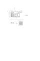
図1は携帯端末2が本技術の画像処理装置としての機能を備える例である。携帯端末2とは、スマートフォンやタブレット機器等の装置である。
携帯端末2には、1台の撮像装置1から、撮像している動画としてのショットVD1が送信されてくる。
撮像装置1と携帯端末2の通信は、例えば有線通信で行われたり、無線通信(例えば近距離無線通信など)で行われる。FIG. 1 is an example in which the
A shot VD1 as a moving image being imaged is transmitted from one
Communication between the
携帯端末2は撮像装置1から供給されるショットVD1について、クロップ処理(切り出し処理)を行って、ショットVD2,VD3,VD4を生成する。また携帯端末2は、ショットVD1,VD2,VD3,VD4を選択可能な画像とし、スイッチング処理で逐次主画像として選択して動画コンテンツCTを生成し、送信出力、表示出力、記録、アップロード等を行うことができる。
The
なお以下では、複数のショットを区別せずに総称する場合や、特に限定されない或る1つのショットを指す場合などには、「ショットVD」の用語を用いる。
また図1では、ショットVD1には添え字として「(CS)」を付加しているが、これは撮像した画角全体の画像であることを表すものとする。つまり上記の定義で言う「クロップ画像」ではなく「撮像画像」である。
一方で、ショットVD2,VD3,VD4には添え字として「(CR)」を付加しているが、これは撮像画像から切り出し(クロップ)された画像であることを表すものとする。
なお添え字「(CS)」「(CR)」については図2,図3,図4,図5,図12,図13,図14でも同様に付している。Note that hereinafter, the term "shot VD" will be used when referring to a plurality of shots generically without distinguishing them, or when referring to a certain shot that is not particularly limited.
Further, in FIG. 1, the subscript "(CS)" is added to the shot VD1, which indicates that the shot VD1 is an image taken at the entire angle of view. In other words, it is not a "cropped image" as defined above, but a "captured image."
On the other hand, "(CR)" is added as a subscript to the shots VD2, VD3, and VD4, which indicates that they are images cut out (cropped) from the captured image.
Note that the subscripts "(CS)" and "(CR)" are similarly attached in FIGS. 2, 3, 4, 5, 12, 13, and 14.
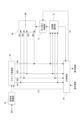
図2は複数の撮像装置1を使用するとともに、スイッチャー3が本技術の画像処理装置としての機能を備える例である。
スイッチャー3とは、複数系統の入力画像に対して出力画像(主画像)を選択するスイッチングを行う機器である。例えば通常はオペレータが手動でスイッチング操作を行うが、本実施の形態では手動スイッチングと自動スイッチングが選択できるようにすることが想定される。FIG. 2 is an example in which a plurality of
The
この例では、スイッチャー3に対しては、3台の撮像装置1からそれぞれショットVD1,VD2,VD3が送信されてくる。それぞれの撮像装置1は、イベント等を撮像した撮像画像を、1つのショットとして出力する。
各撮像装置1は、例えば有線通信や無線通信によりショットVDとしての動画をスイッチャー3に送信する。
スイッチャー3はショットVD1,VD2,VD3のそれぞれからクロップ画像を生成することができる。例えばショットVD1からクロップ画像としてのショットVD4,VD5を生成する。またショットVD3からクロップ画像としてのショットVD6を生成する。この場合、スイッチャー3は、ショットVD1,VD2,VD3,VD4,VD5,VD6を主画像として選択可能な画像とし、スイッチング処理で逐次主画像として選択して動画コンテンツCTを生成し、送信出力、表示出力、記録、アップロード等を行うことができる。
撮像画像としての1つのショットVDからいくつのクロップ画像を生成するかはユーザ操作等により任意に決めることができる。どの撮像画像を対象としてクロップ処理を行うかということも任意である。In this example, shots VD1, VD2, and VD3 are transmitted to the
Each
The
The number of cropped images to be generated from one shot VD as a captured image can be arbitrarily determined by a user operation or the like. It is also arbitrary which captured image is subjected to crop processing.
図3は複数の撮像装置を使用するとともに、コンピュータ装置5が本技術の画像処理装置としての機能を備える例である。コンピュータ装置5とは例えばパーソナルコンピュータ等である。但し上述の携帯端末2であってもよい。
この例でも図2と同様に、3台の撮像装置1からショットVD1,VD2,VD3が送信されてくるものとしている。コンピュータ装置5は、ショットVD1,VD2,VD3のそれぞれからクロップ画像を生成し、例えばショットVD1,VD2,VD3,VD4,VD5,VD6を選択可能な画像とする。そしてスイッチング処理で逐次主画像として選択して動画コンテンツCTを生成し、送信出力、表示出力、記録、アップロード等を行うことができる。
各撮像装置1とコンピュータ装置5の通信は、例えば有線通信で行われたり、無線通信(例えば近距離無線通信など)で行われる。FIG. 3 is an example in which a plurality of imaging devices are used and the
In this example as well, it is assumed that shots VD1, VD2, and VD3 are transmitted from three
Communication between each
図4は、撮像装置1とネットワーク6を介して通信するクラウドスイッチャー4が本技術の画像処理装置としての機能を備える例である。
ネットワーク6は、例えばインターネット、LAN(Local Area Network)、VPN(Virtual Private Network:仮想専用網)、イントラネット、エキストラネット、衛星通信網、CATV(Community Antenna TeleVision)通信網、電話回線網、移動体通信網等の各種の形態が想定される。FIG. 4 is an example in which the
The network 6 includes, for example, the Internet, LAN (Local Area Network), VPN (Virtual Private Network), intranet, extranet, satellite communication network, CATV (Community Antenna TeleVision) communication network, telephone line network, and mobile communication. Various forms such as a net are assumed.
この例では、撮像装置1が、撮像画像としてのショットVD1と、クロップ画像としてのショットVD2,VD3を、ネットワーク6を介してクラウドスイッチャー4に送信する例としている。
クラウドスイッチャー4は、ショットVD1からクロップ画像としてのショットVD4,VD5を生成する。そしてショットVD1,VD2,VD3,VD4,VD5をスイッチング処理で逐次切り替えて動画コンテンツCTを生成し、ネットワーク6を介して送信出力する。In this example, the
The
図5は、撮像装置1が本技術の画像処理装置としての機能を備える例である。
例えば撮像装置1では、撮像を行って撮像画像としてのショットVD1を生成するとともに、内部的なクロップ処理で例えば複数のショットVD2,VD3,VD4を生成する。そしてショットVD1,VD2,VD3,VD4を対象として自動的なスイッチング処理を行って、動画コンテンツCTを生成し、出力する。FIG. 5 is an example in which the
For example, the
以上、本実施の形態の画像処理装置となり得る具体的な機器の例を挙げたが、これらは一例であり、他にも具体的な機器の例は多様に想定される。
また、図1,図2,図3,図4の例では、撮像装置1から送信出力するショットVDの例と、本実施の形態の画像処理装置に該当する携帯端末2、スイッチャー3、コンピュータ装置5、クラウドスイッチャー4の組み合わせを示したが、この組み合わせに限定されるものではない。あくまでショット出力の例と、画像処理装置となる機器の例を挙げたものであるため、図示していない他の組み合わせも想定される。
また図1,図2,図3,図4,図5の携帯端末2、スイッチャー3、コンピュータ装置5、クラウドスイッチャー4、撮像装置1は、スイッチング処理を行って動画コンテンツCTを出力するとしたが、スイッチングを行わずに、クロップ画像を含む複数のショットを出力するものでもよい。Although examples of specific devices that can serve as the image processing apparatus of this embodiment have been given above, these are just examples, and various other examples of specific devices can be envisioned.
In addition, in the examples of FIGS. 1, 2, 3, and 4, an example of a shot VD transmitted and output from the
Furthermore, it is assumed that the
そして以上の例のような本開示の画像処理装置となる機器ではユーザインタフェース制御により、ユーザがクロップ設定を指示することが可能とされるものとなる。 In the device serving as the image processing apparatus of the present disclosure as in the above example, the user can instruct crop settings through user interface control.
以下では、例えば図1のような撮像装置1と携帯端末2のような例を想定して、実施の形態の構成及び動作の例を説明していく。
Below, an example of the configuration and operation of the embodiment will be described assuming an example such as the
まず撮像装置1の構成例を図6で説明する。
図6に示すように撮像装置1は、レンズ系11、撮像素子部12、カメラ信号処理部13、記録制御部14、表示部15、出力部16、操作部17、カメラ制御部18、メモリ部19、ドライバ部22を有する。First, a configuration example of the
As shown in FIG. 6, the
レンズ系11は、カバーレンズ、ズームレンズ、フォーカスレンズ等のレンズや絞り機構などを備える。このレンズ系11により、被写体からの光(入射光)が導かれ撮像素子部12に集光される。
The
撮像素子部12は、例えば、CMOS(Complementary Metal Oxide Semiconductor)型やCCD(Charge Coupled Device)型などのイメージセンサ12a(撮像素子)を有して構成される。
この撮像素子部12では、イメージセンサ12aで受光した光を光電変換して得た電気信号について、例えばCDS(Correlated Double Sampling)処理、AGC(Automatic Gain Control)処理などを実行し、さらにA/D(Analog/Digital)変換処理を行う。そしてデジタルデータとしての撮像信号を、後段のカメラ信号処理部13やカメラ制御部18に出力する。The
The
カメラ信号処理部13は、例えばDSP(Digital Signal Processor)等により画像処理プロセッサーとして構成される。このカメラ信号処理部13は、撮像素子部12からのデジタル信号(撮像画像信号)に対して、各種の信号処理を施す。例えばカメラプロセスとしてカメラ信号処理部13は、前処理、同時化処理、YC生成処理、解像度変換処理、コーデック処理等を行う。
The camera
前処理では、撮像素子部12からの撮像画像信号に対して、R,G,Bの黒レベルを所定のレベルにクランプするクランプ処理や、R,G,Bの色チャンネル間の補正処理等を行う。
同時化処理では、各画素についての画像データが、R,G,B全ての色成分を有するようにする色分離処理を施す。例えば、ベイヤー配列のカラーフィルタを用いた撮像素子の場合は、色分離処理としてデモザイク処理が行われる。
YC生成処理では、R,G,Bの画像データから、輝度(Y)信号および色(C)信号を生成(分離)する。
解像度変換処理では、各種の信号処理が施された画像データに対して、解像度変換処理を実行する。In the preprocessing, clamping processing for clamping the R, G, and B black levels to predetermined levels, and correction processing between the R, G, and B color channels are performed on the captured image signal from the
In the simultaneous processing, color separation processing is performed so that the image data for each pixel includes all R, G, and B color components. For example, in the case of an image sensor using a Bayer array color filter, demosaic processing is performed as color separation processing.
In the YC generation process, a luminance (Y) signal and a color (C) signal are generated (separated) from R, G, and B image data.
In the resolution conversion process, the resolution conversion process is performed on image data that has been subjected to various types of signal processing.
カメラ信号処理部13におけるコーデック処理では、以上の各種処理が施された画像データについて、例えば記録用や通信用の符号化処理やファイル生成を行う。
例えば1つのショットVDとなる動画として出力するストリーム画像データとしての処理や、動画記録のための画像ファイルの生成などを行う。
なおカメラ信号処理部13は、クロップ処理を行って1又は複数のショットとしてのストリーム画像データを生成することもできる。
また図6では音声処理系については図示を省略しているが、実際には音声収録系、音声処理系を有し、ストリーム画像データや記録用の画像ファイルには動画としての画像データとともに音声データも含まれるようにしてもよい。In the codec processing in the camera
For example, it performs processing as stream image data to be output as a moving image that becomes one shot VD, and generates an image file for recording a moving image.
Note that the camera
Although the audio processing system is not shown in Figure 6, it actually has an audio recording system and an audio processing system, and stream image data and recording image files contain audio data as well as image data as a moving image. may also be included.
記録制御部14は、例えば不揮発性メモリによる記録媒体に対して記録再生を行う。記録制御部14は例えば記録媒体に対し動画データや静止画データ等の画像ファイルやサムネイル画像等を記録する処理を行う。
記録制御部14の実際の形態は多様に考えられる。例えば記録制御部14は、撮像装置1に内蔵されるフラッシュメモリとその書込/読出回路として構成されてもよいし、撮像装置1に着脱できる記録媒体、例えばメモリカード(可搬型のフラッシュメモリ等)に対して記録再生アクセスを行うカード記録再生部による形態でもよい。また撮像装置1に内蔵されている形態としてHDD(Hard Disk Drive)などとして実現されることもある。The
The actual form of the
表示部15は撮像者に対して各種表示を行う表示部であり、例えば撮像装置1の筐体に配置される液晶パネル(LCD:Liquid Crystal Display)や有機EL(Electro-Luminescence)ディスプレイ等のディスプレイデバイスによる表示パネルやビューファインダーとされる。
表示部15は、カメラ制御部18の指示に基づいて表示画面上に各種表示を実行させる。
例えば表示部15は、記録制御部14において記録媒体から読み出された画像データの再生画像を表示させる。
また表示部15にはカメラ信号処理部13で表示用に解像度変換された撮像画像の画像データが供給され、表示部15はカメラ制御部18の指示に応じて、当該撮像画像の画像データに基づいて表示を行う場合がある。これにより構図確認中の撮像画像である、いわゆるスルー画(被写体のモニタリング画像)が表示される。
また表示部15はカメラ制御部18の指示に基づいて、各種操作メニュー、アイコン、メッセージ等、即ちGUI(Graphical User Interface)としての表示を画面上に実行させる。The
The
For example, the
Further, the
Further, the
出力部16は、外部機器との間のデータ通信やネットワーク通信等を有線又は無線で行う。 例えば外部の情報処理装置、表示装置、記録装置、再生装置等に対してカメラ信号合処理部13で処理された撮像画像データ(例えば動画としてのストリーム画像信号)の送信出力を行う。
特に本実施の形態の場合、出力部16は、画像処理装置の実現例として図1,図2,図3,図4に例示した携帯端末2、スイッチャー3、コンピュータ装置5、クラウドスイッチャー4等の機器に対して、現在撮像している撮像画像又はクロップ画像としてのショットVDを送信する処理を行うことになる。The
Particularly in the case of the present embodiment, the
操作部17は、ユーザが各種操作入力を行うための入力デバイスを総括して示している。具体的には操作部17は撮像装置1の筐体に設けられた各種の操作子(キー、ダイヤル、タッチパネル、タッチパッド等)を示している。
操作部17によりユーザの操作が検知され、入力された操作に応じた信号はカメラ制御部18へ送られる。The
The
カメラ制御部18はCPU(Central Processing Unit)を備えたマイクロコンピュータ(演算処理装置)により構成される。
メモリ部19は、カメラ制御部18が処理に用いる情報等を記憶する。図示するメモリ部19としては、例えばROM(Read Only Memory)、RAM(Random Access Memory)、フラッシュメモリなど包括的に示している。
メモリ部19はカメラ制御部18としてのマイクロコンピュータチップに内蔵されるメモリ領域であってもよいし、別体のメモリチップにより構成されてもよい。
カメラ制御部18はメモリ部19のROMやフラッシュメモリ等に記憶されたプログラムを実行することで、この撮像装置1の全体を制御する。
例えばカメラ制御部18は、撮像素子部12のシャッタースピードの制御、カメラ信号処理部13における各種信号処理の指示、ユーザの操作に応じた撮像動作や記録動作、記録した画像ファイルの再生動作、レンズ鏡筒におけるズーム、フォーカス、絞り調整等のレンズ系11の動作、ユーザインタフェース動作等について、必要各部の動作を制御する。The
The
The
The
For example, the
メモリ部19におけるRAMは、カメラ制御部18のCPUの各種データ処理の際の作業領域として、データやプログラム等の一時的な格納に用いられる。
メモリ部19におけるROMやフラッシュメモリ(不揮発性メモリ)は、CPUが各部を制御するためのOS(Operating System)や、画像ファイル等のコンテンツファイルの他、各種動作のためのアプリケーションプログラムや、ファームウエア等の記憶に用いられる。The RAM in the
The ROM and flash memory (non-volatile memory) in the
ドライバ部22には、例えばズームレンズ駆動モータに対するモータドライバ、フォーカスレンズ駆動モータに対するモータドライバ、絞り機構のモータに対するモータドライバ等が設けられている。
これらのモータドライバはカメラ制御部18からの指示に応じて駆動電流を対応するドライバに印加し、フォーカスレンズやズームレンズの移動、絞り機構の絞り羽根の開閉等を実行させることになる。The
These motor drivers apply drive currents to the corresponding drivers in response to instructions from the
次に本実施の形態の画像処理装置として機能する情報処理装置70の構成を図7に示す。
例えば携帯端末2やコンピュータ装置5は、この情報処理装置70として構成される。スイッチャー3、クラウドスイッチャー4等も、この情報処理装置70と同等の構成を有することで、本実施の形態の画像処理装置として機能できる。Next, FIG. 7 shows the configuration of an
For example, the
図7において、情報処理装置70のCPU71は、ROM72に記憶されているプログラム、または記憶部79からRAM73にロードされたプログラムに従って各種の処理を実行する。RAM73にはまた、CPU71が各種の処理を実行する上において必要なデータなども適宜記憶される。
CPU71、ROM72、およびRAM73は、バス74を介して相互に接続されている。このバス74にはまた、入出力インタフェース75も接続されている。In FIG. 7, a
The
入出力インタフェース75には、操作子や操作デバイスよりなる入力部76が接続される。
例えば入力部76としては、キーボード、マウス、キー、ダイヤル、タッチパネル、タッチパッド、リモートコントローラ等の各種の操作子や操作デバイスが想定される。
入力部76によりユーザの操作が検知され、入力された操作に応じた信号はCPU71によって解釈される。The input/
For example, as the
A user's operation is detected by the
また入出力インタフェース75には、LCD或いは有機ELパネルなどよりなる表示部77や、スピーカなどよりなる音声出力部78が一体又は別体として接続される。
表示部77は各種表示を行う表示部であり、例えば情報処理装置70の筐体に設けられるディスプレイデバイスであったり、情報処理装置70に接続される別体のディスプレイデバイス等により構成される。
表示部77は、CPU71の指示に基づいて表示画面上に各種の画像処理のための画像や処理対象の動画等の表示を実行する。また表示部77はCPU71の指示に基づいて、各種操作メニュー、アイコン、メッセージ等、即ちGUI(Graphical User Interface)としての表示を行う。Further, a
The
The
入出力インタフェース75には、ハードディスクや固体メモリなどより構成される記憶部79や、モデムなどより構成される通信部80が接続される場合もある。
通信部80は、インターネット等の伝送路を介しての通信処理を行ったり、各種機器との有線/無線通信、バス通信などによる通信を行う。The input/
The
入出力インタフェース75にはまた、必要に応じてドライブ82が接続され、磁気ディスク、光ディスク、光磁気ディスク、或いは半導体メモリなどのリムーバブル記録媒体81が適宜装着される。
ドライブ82により、リムーバブル記録媒体81からは画像ファイル等のデータファイルや、各種のコンピュータプログラムなどを読み出すことができる。読み出されたデータファイルは記憶部79に記憶されたり、データファイルに含まれる画像や音声が表示部77や音声出力部78で出力されたりする。またリムーバブル記録媒体81から読み出されたコンピュータプログラム等は必要に応じて記憶部79にインストールされる。A
The
この情報処理装置70では、例えば本開示の画像処理装置としての処理のためのソフトウエアを、通信部80によるネットワーク通信やリムーバブル記録媒体81を介してインストールすることができる。或いは当該ソフトウエアは予めROM72や記憶部79等に記憶されていてもよい。
In this
<2.画像処理装置の機能構成例>
本実施の形態の画像処理装置は、例えば情報処理装置70のCPU71に、ソフトウエア(アプリケーションプログラム)により、図8の機能構成が備えられることで実現される。<2. Functional configuration example of image processing device>
The image processing apparatus of this embodiment is realized by, for example, providing the
即ち情報処理装置70(又はCPU71)は、ユーザインタフェース制御部(UI制御部)30とクロップ処理部36を少なくとも備えることで、本実施の形態の画像処理装置として機能する。
また情報処理装置70(又はCPU71)は、さらに切り替え制御部33を有する場合もある。
さらに情報処理装置70(又はCPU71)は、主画像選択部31、被写体認識部34の一方或いは両方を備える場合もある。That is, the information processing device 70 (or CPU 71) functions as the image processing device of this embodiment by including at least the user interface control section (UI control section) 30 and the
Further, the information processing device 70 (or CPU 71) may further include a
Further, the information processing device 70 (or CPU 71) may include one or both of the main
例えば図1の携帯端末2や図3のコンピュータ装置5は、図7の情報処理装置70の構成とされ、CPU71が図8の機能構成を備えることで本実施の形態の画像処理装置として機能する。
また図2のスイッチャー3や図4のクラウドスイッチャー4は、図7に相当する構成(もしくは少なくともCPU71に相当する構成)を有し、CPU71が図8の機能構成を備えるようにすることで本実施の形態の画像処理装置として機能する。
また図5のように撮像装置1が画像処理装置として機能する場合は、例えば図6のカメラ信号処理部13又はカメラ制御部18が図8の機能構成を備えることで本実施の形態の画像処理装置として機能する。For example, the
In addition, the
Further, when the
例えばこのように実現される本実施の形態の画像処理装置は、動画制作におけるスイッチング(主画像の切り替え)に供される複数のショットとして、クロップ画像としてのショットを生成したり、ユーザ操作などに応じて、そのクロップ領域の設定等を行う装置である。特にクロップ領域設定に関しては、後述するオート、セミオート、マニュアルの各モードや、そのための画面を用意することで、操作性のよいクロップ設定環境を提供する。 For example, the image processing device of this embodiment realized in this manner can generate shots as cropped images as multiple shots used for switching (switching of main images) in video production, or can generate shots as cropped images in response to user operations. This device sets the crop area accordingly. In particular, with regard to crop area settings, an easy-to-operate crop setting environment is provided by providing automatic, semi-auto, and manual modes, which will be described later, as well as screens for these modes.
図8の各機能について説明する。
UI制御部30は、例えば表示部77等において、スイッチング動作のモニタ画面やクロップ設定のための画面の表示させる制御や、ユーザ操作を受け付ける制御を行う機能である。
具体的にはUI制御部30は、撮像画像を表示する撮像画像表示領域と、クロップ処理部36で切り出されたクロップ画像を表示するクロップ画像表示領域とを含むマルチビュー画面100(第1画面)の表示制御処理を行う。
またUI制御部30は、表示をマルチビュー画面100から、撮像画像からのクロップ領域を設定するクロップ設定画面200(第2画面)へ遷移させる表示制御処理を行う。
またUI制御部30は、クロップ設定画面200においてクロップ領域に関する少なくとも1つの座標を指定する第1のユーザ操作、及びクロップ領域に関する被写体を指定する第2のユーザ操作を受け付ける処理を行う。
またUI制御部30は、第1のユーザ操作又は第2のユーザ操作に基づいてクロップ領域を設定する処理を行う。Each function in FIG. 8 will be explained.
The
Specifically, the
The
The
The
主画像選択部31は、複数のショットVDのうちで主画像とする一の画像を選択する機能である。
つまり動画コンテンツにおいて使用する次のショットVDとして、適切なショットを選択する処理を行う。The main
In other words, processing is performed to select an appropriate shot as the next shot VD to be used in the video content.
切り替え制御部33は、主画像を切り替える機能である。例えば主画像とされたショットVDを、ある程度の期間(例えば3秒から7秒程度)、主画像として継続させた後、次のショットVDに切り替えるスイッチング動作の制御を行う。
この切り替え制御部33による主画像の切り替えタイミングについては各種の例が考えられる。例えば切り替え制御部33は、各ショットVDの内容(被写体認識)、継続期間長、クロップ設定の変化などに応じて切り替えタイミングの判定を行うことができる。
また切り替え制御部33は、ユーザ操作に応じて切り替えタイミングの判定を行う場合もある。The switching
Various examples can be considered regarding the switching timing of the main image by the switching
The switching
クロップ処理部36は、撮像画像の一部の領域を切り出す処理を行う機能である。
このクロップ処理部は、UI制御部30により取得したユーザの意向に沿ったクロップ領域の設定情報や、オート、セミオート、マニュアルの各モードの選択に基づいて、クロップ元の撮像画像から一部領域を切り出してクロップ画像を生成する。The
This crop processing unit selects a partial area from the source captured image based on the crop area setting information according to the user's intention acquired by the
クロップ画像の例を図9に示す。これは1台の撮像装置1でインタビューの場面の撮像を行い、放送等をすることを想定した画像例である。
クロップ処理部36は、例えばショットVD1として示した1つの撮像画像から一部の領域を切り出して、クロップ画像としてのショットVDを生成する。ここでは例えば4人の人物が写っている撮像画像から、各被写体人物を切り出して4つのクロップ画像としてのショットVD2,VD3,VD4,VD5を生成する例を示している。An example of a cropped image is shown in FIG. This is an image example assuming that an interview scene will be imaged with one
The
この場合、撮像画像であるショットVD1の画像において、例えばクロップ枠CRWで示される4つの領域が、それぞれ切り出されて、それぞれショットVD2,VD3,VD4,VD5とされるとする。図ではクロップ画像としてのショットVD2,VD3を例示している。
クロップ処理部36は、このように1つの画像の一部を切り出して1又は複数のクロップ画像を生成する処理を、例えばUI制御部30が認識したユーザ操作に基づく各種設定(クロップ領域設定やクロップモード設定など)に応じて実行する。In this case, assume that in the image of shot VD1, which is a captured image, four areas indicated by, for example, cropping frame CRW are respectively cut out and set as shots VD2, VD3, VD4, and VD5, respectively. The figure illustrates shots VD2 and VD3 as cropped images.
The
クロップモードがオートモードとされた場合は、クロップ処理部36は例えば動画のフレーム毎に自動的にクロップ領域(クロップ枠CRWの領域)を判定し、切り出しを行う。このオートモードでのクロップ処理のために被写体認識が行われる。
またセミオートモードの場合、ユーザが被写体(例えば被写体人物)を指定することで、その被写体を中心に切り出すような切り出し処理が行われる。When the crop mode is set to auto mode, the
In the case of semi-automatic mode, when the user specifies a subject (for example, a person), a cutting process is performed in which the subject is centered.
これらオートモードやセミオートモードの処理のために画面内の被写体の認識が必要になったり、画面内で切り出しの候補となる被写体の領域の判定などが必要となる。
このため図8のように画像処理装置には被写体認識部34としての機能が設けられる。
被写体認識部34は、供給されたショットVDの画像に対する画像解析等の処理を行い、ショットVD内の被写体を認識する機能である。
例えば顔検出、人検出、姿勢推定などで被写体を検出、追尾する処理を行うことがある。
また、顔識別(個人の識別)を行い、被写体が誰か(撮像しているイベントにおける主役などの重要被写体か否か)を認識する処理を行うことがある。
また、顔パーツ検出で検出した口の動きから、話者を検出する処理を行うことがある。For processing in these auto modes and semi-auto modes, it is necessary to recognize the subject within the screen, and it is necessary to determine the area of the subject that is a candidate for cropping within the screen.
For this reason, as shown in FIG. 8, the image processing device is provided with a function as a
The
For example, processing for detecting and tracking a subject may be performed using face detection, human detection, pose estimation, etc.
In addition, face recognition (individual identification) may be performed to recognize who the subject is (whether or not the subject is an important subject such as the main character in the event being imaged).
Additionally, processing may be performed to detect the speaker based on the mouth movements detected by facial part detection.
また被写体認識部34は、認識結果から、ショット情報を抽出する。
ショット情報とは、誰が写っているかという情報であったり、構図(配置)、カメラワークなどの情報が想定される。The
Shot information is assumed to be information about who is in the picture, composition (layout), camera work, etc.
誰が写っているかという被写体の情報は、例えば画像内で大きく映っている被写体を対象とする。
構図(配置)の情報とは、俯瞰ショット、引き(フルショット、ニーショット)、寄り(ウエストショット、バストショット、アップショット)などの種別であったり、ショットVDがいわゆる日の丸構図、三分割法、など、構図や被写体配置の類型のどれに該当するかの情報などである。またショットVDの画像内の被写体サイズなどの種別も構図の情報に含まれる。
カメラワークの情報とは、固定、フォロー、パン、ズーム、ドリー等のカメラワーク自体を示す情報である。
これらのショット情報に基づいて、次に主画像とするショットを選択したり、クロップ領域の候補を判定したりすることもできる。Information on the subject, such as who is photographed, is for example a subject that appears large in the image.
Composition (arrangement) information includes types such as bird's-eye shot, pull (full shot, knee shot), close-up shot (waist shot, bust shot, close-up shot), and shot VD includes so-called Hinomaru composition, rule of thirds, etc. This information includes information on which type of composition and subject placement the image falls under. Further, the composition information also includes the type such as the size of the subject in the image of the shot VD.
Camera work information is information indicating camera work itself such as fixation, following, panning, zooming, dolly, etc.
Based on this shot information, it is also possible to select a shot to be the next main image, or to determine candidates for a cropping area.
また被写体認識部34は、認識結果やショット情報に基づいて、当該ショットVDの画像分類を判定できる。
例えば、画像分類として、全てのショットVDを、主要被写体ショット(主役ショット/話者ショット)、脇役ショット、全体ショット(大人数或いは正面のショット)等に分類することもできる。
このようなショット情報に基づく画像分類の判定は機械学習に基づいて行われることが考えられる。
また全体ショットは、最も正面の画像、最も引きの画像、最も被写体人数が多い画像などの条件で判定してもよいし、ユーザの指定に基づいて特定されるものでもよい。例えば常に被写体の正面から引きで撮像を行う撮像装置1が配置されている場合、その撮像装置1によるショットVDは、常に全体ショットであるとして、ユーザが設定することも考えられる。Furthermore, the
For example, as image classification, all shots VD can be classified into main subject shots (main character shots/speaker shots), supporting character shots, whole shots (large group shots or front shots), and the like.
It is conceivable that image classification determination based on such shot information is performed based on machine learning.
Further, the overall shot may be determined based on conditions such as the most frontal image, the most distant image, or the image with the largest number of subjects, or may be specified based on a user's designation. For example, if an
例えば図9の場合、各ショットの画像分類は次のようになる。
ショットVD1はインタビュー場面の正面から全体を引きで撮っているショットであり、「全体ショット」に該当する。
ショットVD2は、インタビューを受けている人の一人を切り出した画像であるが、この時点では、この画像に写る人が話者でとなっている。例えば画像から検出される口の動きなどにより話者と判定された場合、このショットVD2が現時点の「話者ショット」又は「主要被写体ショット」と判定される。話者ショットと判定されるショットVDは、話者が変わるたびに変更されることになる。
ショットVD3は、話者以外の人のショットであるため、この時点では「脇役ショット」と判定されることになる。後にこの人物が話す場面となったら、このショットVD3が「話者ショット」又は「主要被写体ショット」と判定される。
このような画像分類によって、スイッチングを行うことも想定される。
なお被写体認識部34の処理は必ずしも画像処理装置内で行われなくても良い。For example, in the case of FIG. 9, the image classification of each shot is as follows.
Shot VD1 is a shot that captures the entire interview scene from the front, and corresponds to an "overall shot."
Shot VD2 is an image of one of the people being interviewed, but at this point, the person in this image is the speaker. For example, if it is determined that the person is the speaker based on mouth movements detected from the image, this shot VD2 is determined to be the current "speaker shot" or "main subject shot". The shot VD determined to be a speaker shot is changed every time the speaker changes.
Shot VD3 is a shot of a person other than the speaker, and therefore is determined to be a "supporting character shot" at this point. When a scene in which this person speaks later occurs, this shot VD3 is determined to be a "speaker shot" or a "main subject shot."
It is also assumed that switching will be performed based on such image classification.
Note that the processing of the
以上の図8の機能による画像処理装置の処理の流れの例を図10で説明する。
例えば1つの撮像装置1からショットVD1が画像処理装置に供給されるとする。
被写体認識部34は、ショットVD1について被写体認識処理を行う。被写体認識処理は、ショットVD1の画像解析による被写体認識に基づいて、クロップすべき被写体の判定や、クロップ領域の候補を判定する処理を行う。また例えば被写体人物の顔領域、身体全体の領域、バストアップの領域などを判定することも想定される。An example of the processing flow of the image processing apparatus based on the functions shown in FIG. 8 will be described with reference to FIG.
For example, assume that a shot VD1 is supplied from one
The
クロップ処理部36は、ショットVD1の各フレームから適切な領域の切り出し処理を行う。切り出された画像(クロップ画像)が、例えばそれぞれショットVD2・・・VDnとされる。
なおクロップ処理部36は、マニュアルモードの場合は、UI制御部30から指示される、ユーザの操作により指定される領域のクロップ処理を行う。
またクロップ処理部36は、セミオートモードの場合は、UI制御部30から指示される、ユーザの操作により指定される被写体について、被写体認識の結果に基づいてクロップ領域を自動設定し、クロップ処理を行う。
またクロップ処理部36は、オートモードの場合は、被写体認識の結果に基づいてクロップ対象の被写体を判定し、その被写体のクロップ領域を自動設定し、クロップ処理を行う。
これらの処理のため、クロップモード情報やユーザの操作情報に応じた指示情報を含むコントロール情報CTLがUI制御部30からクロップ処理部36に通知される。The
Note that in the manual mode, the
In addition, in the case of the semi-auto mode, the
In addition, in the auto mode, the
For these processes, control information CTL including crop mode information and instruction information according to user operation information is notified from the
クロップ元の撮像画像であるショットVD1及びクロップ画像であるショットVD2・・・VDnは、それぞれ切り替え部40に供給され、スイッチングされる。即ちショットVD1、VD2・・・VDnのいずれかが切り替え部40で選択されて、現時点の主画像MPとして出力される。
The shot VD1, which is the cropped image, and the shots VD2, . . ., VDn, which are the cropped images, are each supplied to the
切り替え部40によりショットVDのスイッチングが行われることで、出力される動画コンテンツは、主画像が逐次、切り替わり、視聴者を飽きさせにくいものとなる。
図11の第1例、第2例には、動画コンテンツCTとしての主画像の切り替えを模式的に示している。
図の横方向が時間軸を示し、1つの動画コンテンツとして、ショットVD1,VD2,VD3,VD4が時間軸上で逐次主画像MPとして切り替えられて出力される状態を示している。
例えば各ショットが3秒から7秒程度の期間長で出力されながら、切り替えられていく。特に、1つの撮像画像から複数のクロップ画像を生成する場合でも、それらがスイッチングされて動画コンテンツとされることで、視聴者によってはよりおもしろみや臨場感のある内容となりやすい。By switching the shot VD by the switching
The first and second examples in FIG. 11 schematically show switching of main images as video content CT.
The horizontal direction of the figure indicates the time axis, and shows a state in which shots VD1, VD2, VD3, and VD4 are sequentially switched and output as the main image MP on the time axis as one moving image content.
For example, each shot is output for a period of about 3 to 7 seconds while being switched. In particular, even when a plurality of cropped images are generated from one captured image, the content may be more interesting and realistic depending on the viewer by being switched to create video content.
このようなスイッチングのために、図10の切り替え制御部33は、切り替え判定処理により切り替えタイミングを判定し、切り替えタイミングにおいて、切り替え部40のスイッチング動作を制御する。
即ち切り替え制御部33は、ユーザの手動のスイッチング操作情報SSがUI制御部30から入力されることに応じて、ユーザが指示したショットVDを、主画像MPとして出力するように切り替え部40を制御することができる。For such switching, the switching
That is, the switching
またユーザ操作にかかわらずにスイッチング及び主画像の選択が自動的に行われるようにしてもよい。
例えば図示のようにショットVD1、VD2・・・VDn、もしくはそれらのショット情報や画像分類の情報等が、主画像選択部31に供給されて、主画像選択部31が、次の主画像を選択するということが考えられる。
主画像選択部31は、次の主画像を選択したら、それをUI制御部30に通知して表示させたり、切り替え制御部33に通知して所定のタイミングでスイッチングが行われるようにする。Furthermore, switching and selection of the main image may be performed automatically regardless of user operations.
For example, as shown in the figure, shots VD1, VD2...VDn, their shot information, image classification information, etc. are supplied to the main
When the main
主画像選択部31による次に主画像とするショットの選択処理の例は各種考えられる。
例えば各ショットVDが、規則的に順番に選択されるようにしてもよい。各ショットを主画像とする継続期間長は、固定時間であったり、可変時間であったりすることが考えられる。
このような動画コンテンツは、各種のアングルの画像や、各被写体人物のアップ画像等が切り替わることで、単に1つの全体画面を継続して写すよりはコンテンツとしての充実したものとすることができる。しかし、常に特定の順番で定期的に画像が切り替わるものであり、視聴者にとっては退屈な動画と感じられやすい。Various examples of the process of selecting the next shot to be the main image by the main
For example, each shot VD may be selected in regular order. The duration of each shot as the main image may be a fixed time or a variable time.
By switching between images from various angles, close-up images of each subject, etc., such video content can be more fulfilling than simply continuously capturing one entire screen. However, the images always change periodically in a specific order, and viewers tend to find the videos boring.
そこで各ショットVDの選択順序をランダムにすることも考えられる。視聴者が退屈さを感じることを若干解消できる。 Therefore, it is conceivable to randomize the selection order of each shot VD. This can alleviate some of the boredom that viewers feel.
より好適な例としては、各ショットの画像分類に応じて継続期間長を異なるようにすることが考えられる。
即ち継続期間長を、全体ショットは時間Ta、主役ショットは時間Tb、脇役ショットは時間Tcとする。そしてTb>Tc>Taとする。或いはTb>Ta>Tcとしてもよい。即ち主役ショットの継続期間長を最も長くする。脇役ショットと全体ショットは、いずれかの継続期間長が最も短くなるようにする。
一例として継続時間長は、主役ショットは8秒、脇役ショットは6秒、全体ショットは4秒などとする。A more preferable example is to set the duration length to be different depending on the image classification of each shot.
That is, the duration length is set to be time Ta for the overall shot, time Tb for the main shot, and time Tc for the supporting shot. Then, Tb>Tc>Ta. Alternatively, Tb>Ta>Tc may be satisfied. That is, the duration of the main shot is made the longest. The duration of either of the supporting character shots and the overall shot is set to be the shortest.
As an example, the duration length may be 8 seconds for the main character shot, 6 seconds for the supporting character shot, and 4 seconds for the entire shot.
そして、主画像選択部31で選択されたショットVDが、そのショットVDの画像分類PDに応じて設定された継続期間長ずつ、主画像MPとして出力されていく。
図11の第1例では、ショットVD1は全体ショット、ショットVD2は主役ショット、ショットVD3、VD4は脇役ショットとして、このような例を示している。
即ち最初にショットVD1が時間Taだけ継続され、次にショットVD2が時間Tbだけ継続され、次にショットVD4が時間Tcだけ継続される、というように順次切り替えられていく。この場合、主画像選択部31による選択は、順番でもなければ完全ランダムでもない。Then, the shot VD selected by the main
In the first example of FIG. 11, shot VD1 is the overall shot, shot VD2 is the main shot, and shots VD3 and VD4 are supporting shots.
That is, shot VD1 is first continued for time Ta, then shot VD2 is continued for time Tb, then shot VD4 is continued for time Tc, and so on. In this case, the selection by the main
このようにすることで、動画制作の意図に沿ったスイッチングであって、また固定的なスイッチングタイミングでないことにより視聴者を飽きさせにくくした動画コンテンツCTを自動スイッチングにより容易に実現できるようにしている。
特に主役ショットが主画像MPとして選ばれやすくしたり、継続時間長を長くすることで、主役被写体が十分にフィーチャーされ、しかも場面の切り替えにおいて視聴者に良い意味の緊張感を与えるような動画が実現される。By doing this, it is possible to easily realize video content CT by automatic switching, which is in accordance with the intention of the video production, and which makes it difficult for viewers to get bored because the switching timing is not fixed. .
In particular, by making the main shot more likely to be selected as the main image MP and by increasing the duration, you can create a video that fully features the main subject and gives the viewer a positive sense of tension during scene transitions. Realized.
図11の第2例は、さらに切り替えタイミング(換言すれば主画像MPとしての継続時間長)を変化させることで、よりダイナミクスのある動画コンテンツを実現する例である。
即ちこの第2例は、継続時間長としての全体ショットの時間Ta、主役ショットの時間Tb、脇役ショットの時間Tcについて、Tb>Tc>Ta、又はTb>Ta>Tcとすることは第1例と同様であるが、それぞれの画像分類の継続時間長に幅を持たせる例である。
例えば主役ショットの場合の継続時間長は、時間Tb1、Tb2、Tb3などでバリエーションを持たせる。同様に脇役ショットの継続時間長は、時間Tc1、Tc2、Tc3などとし、全体ショットの継続時間長は、時間Ta1、Ta2、Ta3などとする。
一例として継続時間長は、全体ショットは3.5秒から4秒の間、脇役ショットは4秒から6秒の間、主役ショットは6秒から8秒の間、などとする。
例えば主役ショットの継続時間長は、時間Tb1、Tb2、Tb3が6秒から8秒の間でランダムに設定されるなどとする。脇役ショット、全体ショットも同様である。
これにより、ショットVDの切り替えタイミングの周期性がより薄くなり、緊張感のある動画となりやすい。The second example in FIG. 11 is an example in which moving image content with more dynamics is realized by further changing the switching timing (in other words, the duration of the main image MP).
That is, in this second example, regarding the duration Ta of the entire shot, the time Tb of the main shot, and the time Tc of the supporting shot, setting Tb>Tc>Ta or Tb>Ta>Tc is the first example. This is an example in which the duration of each image classification is varied.
For example, the duration length in the case of the main shot is varied by times Tb1, Tb2, Tb3, etc. Similarly, the durations of supporting shots are times Tc1, Tc2, Tc3, etc., and the durations of all shots are times Ta1, Ta2, Ta3, etc.
As an example, the duration length may be 3.5 seconds to 4 seconds for the overall shot, 4 seconds to 6 seconds for the supporting shot, and 6 to 8 seconds for the main shot.
For example, it is assumed that the duration of the main shot is set randomly between times Tb1, Tb2, and Tb3 between 6 seconds and 8 seconds. The same goes for supporting character shots and overall shots.
As a result, the periodicity of the switching timing of the shot VD becomes less frequent, which tends to create a moving image with a sense of tension.
なお、必ずしも常にTb>Tc>Ta、又はTb>Ta>Tcの関係が守られなくてもよい。例えば多少オーバーラップして、全体ショットは3秒から5秒の間、脇役ショットは4秒から6秒の間、主役ショットは5秒から8秒の間などとしてもよい。 Note that the relationship Tb>Tc>Ta or Tb>Ta>Tc does not necessarily have to be maintained at all times. For example, with some overlap, the overall shot may be set for 3 seconds to 5 seconds, the supporting shot may be set for 4 seconds to 6 seconds, the main shot may be set for 5 seconds to 8 seconds, etc.
図10のUI制御部30は、スイッチング動作やクロップ処理に関したユーザに情報を提示するとともに、ユーザ操作を受け付ける。
具体的には、クロップ処理部36からの各ショットVDやスイッチングの状況についてマルチビュー画面で表示させたり、クロップ設定の画面を提供する。
以下、UI制御部30による表示やユーザの操作入力について詳しく説明する。
The
Specifically, each shot VD and switching status from the
The display by the
<3.マルチビュー画面>
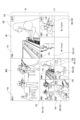
図12はUI制御部30の制御により表示部77(又は表示部15)に表示されるマルチビュー画面100の例を示している。
このマルチビュー画面100は、ユーザに、各ショットVDの画像をモニタリングさせるとともに、現在の主画像や、次の主画像を明示してスイッチングの状況を伝えるための画面である。<3. Multi-view screen>
FIG. 12 shows an example of a
This
図12のマルチビュー画面100は、大きく分けてアッパーサイド(画面上部)USとロワーサイド(画面下部)LSが設定される。
アッパーサイドUSではスイッチング状況を提示する。例えばアッパーサイドUSの右側に、現在、主画像MPとして出力されているショットVDが表示される。
このショット画像内に主画像提示部101が設けられ、現在の主画像であることを示す「PGM」という表示が行われている。例えばライブ中継放送であれば、この主画像が、現在視聴者に視聴されている画像となる。The
The upper side US presents a switching situation. For example, the shot VD currently being output as the main image MP is displayed on the right side of the upper side US.
A main
また画面のアッパーサイドUSの左側に、次に主画像MPとして出力される予定(ネクスト画像MPN)のショットVDが表示される。
例えばユーザ(オペレータ)が手動で次の主画面として予約したショットVDや、自動選択により次の主画像として選択されたショットが表示される。ショット画像内にネクスト提示部102が設けられ、次の主画像であることを示す「NEXT」という表示が行われる。Further, on the left side of the upper side US of the screen, the shot VD that is scheduled to be output next as the main image MP (next image MPN) is displayed.
For example, a shot VD manually reserved by the user (operator) as the next main screen, or a shot automatically selected as the next main image is displayed. A
画面のロワーサイドLSには、アッパーサイドUSの画像と比べて小さい領域で、スイッチング対象として入力されている複数のショットVD1,VD2,VD3・・・がそれぞれ表示される。
この例では、8個のショットVDを表示する領域が用意されており、現在6つのショットVD1,VD2,VD3,VD4,VD5,VD6がスイッチングの対象として入力されているものとしている。
なお、ショット画像が存在しない領域は「No Signal」と表示されている。On the lower side LS of the screen, a plurality of shots VD1, VD2, VD3, . . . that are input as switching targets are displayed in a smaller area than the image on the upper side US.
In this example, an area for displaying eight shots VD is prepared, and six shots VD1, VD2, VD3, VD4, VD5, and VD6 are currently input as switching targets.
Note that the area where no shot image exists is displayed as "No Signal".
このロワーサイドLSには、撮像画像表示領域とクロップ画像表示領域(切り出し画像表示領域)が、そのときの入力画像に応じて用意される。
上述したように、スイッチング対象のショットVDとしては、撮像装置1で撮像された元々の撮像画像や、クロップ画像がある。ここではショットVD1,VD2,VD3が撮像画像、ショットVD4,VD5,VD6がクロップ画像であるとしている。In this lower side LS, a captured image display area and a cropped image display area (cutout image display area) are prepared according to the input image at that time.
As described above, the shot VD to be switched includes the original image captured by the
この例において撮像画像である各ショットVD1,VD2,VD3が表示される領域には、画像種別提示部103が設けられ、その画像種別が表示される。ここでは各ショットVDがHDMI(High-Definition Multimedia Interface:高精細度マルチメディアインターフェース)(登録商標)で伝送された画像であることを示す「HDMI」との表示が行われている例としている。
また、クロップ画像である各ショットVD4,VD5,VD6が表示される領域にはクロップ提示部104が設けられ、「CROP」という表示が行われることで、それらの画像がクロップ画像であること表示される。In this example, an image
Further, a
この例では、ショットVD1,VD2,VD3の表示領域が撮像画像表示領域となり、ショットVD4,VD5,VD6の表示領域がクロップ画像表示領域となる。
なお、スイッチング対象として入力されている全てのショットVDが撮像画像である場合や、全てのショットがクロップ画像である場合もあり得る。そのためロワーサイドLSにおける撮像画像表示領域とクロップ画像表示領域は固定的なものでなく、また常に両方が設けられるものではない。撮像画像表示領域とクロップ画像表示領域は、そのときの入力されるショットVDの種別や数に応じて用意されるものとなる。In this example, the display area for shots VD1, VD2, and VD3 becomes the captured image display area, and the display area for shots VD4, VD5, and VD6 becomes the crop image display area.
Note that there may be cases in which all shots VD input as switching targets are captured images, or cases in which all shots are cropped images. Therefore, the captured image display area and the cropped image display area in the lower side LS are not fixed, and both are not always provided. The captured image display area and the cropped image display area are prepared according to the type and number of shot VDs input at that time.
またこれらの画像に加えて、スイッチングモード提示部105によるスイッチングモードの提示、及びクロップモード提示部106によるクロップモードの提示が行われる。
In addition to these images, the switching
スイッチングモード提示部105は、主画像とされているショットVDの画像に重畳して設けられ、これは主画像のスイッチングが自動で行われるか手動で行われるかを提示する。図の例では「AUTO」とされ、自動スイッチングが行われていることを示すものとなっている。
このスイッチングモード提示部105が例えば「MANUAL」と表示されることで、手動スイッチングが行われていることを示すようにしてもよい。A switching
The switching
なお、このスイッチングモード提示部105は、スイッチングモードを指定する操作子としてもよい。例えば「AUTO」の表示を操作ボタンとし、「AUTO」の表示がクリック等で操作されることでオートスイッチングが開始される。また再度操作されることで自動スイッチングが終了されるようにする。
その場合、自動スイッチングが行われている期間は、「AUTO」の表示が赤色になるなどして、自動スイッチングを行っていることを提示し、手動スイッチングが行われている期間は、「AUTO」の表示が薄くなったり、操作可能な状態を示すようなものとなることで、自動スイッチングを指示するボタンとして認識されるような表示とすることが考えられる。Note that this switching
In that case, during the period when automatic switching is being performed, the "AUTO" display will turn red to indicate that automatic switching is being performed, and during the period when manual switching is being performed, "AUTO" will be displayed. It is conceivable that the display could be dimmed or made to indicate an operable state so that it would be recognized as a button for instructing automatic switching.
クロップモード提示部106は、クロップ画像であるショットVDの画像に重畳して設けられる。
図ではクロップモード提示部106として、ショットVD4について「AUTO」、ショットVD5について「SEMI」、ショットVD6について「FIX」とした表示が行われている例を示している。
「AUTO」はオートモードで設定されたクロップ画像であることを示す。
「SEMI」はセミオートモードで設定されたクロップ画像であることを示す。
「FIX」はマニュアルモードで設定されたクロップ画像であることを示す。The crop
The figure shows an example in which the crop
"AUTO" indicates that the cropped image is set in auto mode.
"SEMI" indicates that the image is a cropped image set in semi-auto mode.
“FIX” indicates a cropped image set in manual mode.
ユーザ(オペレータ)は、このようなマルチビュー画面100によりスイッチング動作の状況や、スイッチングのために入力されている画像、さらにはクロップ画像の内容を確認できる。
The user (operator) can check the status of the switching operation, the image being input for switching, and the contents of the cropped image using such a
なお、図12の画面例はあくまでも一例であり、マルチビュー画面100の構成や表示内容はこれに限られない。他の画面例を図13,図14に示す。
図13は、アッパーサイドUS、ロワーサイドLSの画面構成は図12と同様としているが、各画像の状態や意味をより明確に区別して表示させる例である。Note that the screen example in FIG. 12 is just an example, and the configuration and display contents of the
FIG. 13 shows an example in which the screen configurations of the upper side US and lower side LS are the same as those shown in FIG. 12, but the states and meanings of each image are more clearly distinguished and displayed.
アッパーサイドUSの右側に表示される現在の主画像については、例えば赤色枠Wred(図では太線で示す)で囲むようにすることで、現在の主画像であることを明確にユーザに提示する。
アッパーサイドUSの左側に表示される次の主画像については、例えば青色枠Wblue(図では太破線で示す)で囲むようにすることで、次の主画像であることを明確にユーザに提示する。
即ち色によって現在の主画像と次の主画像を目立つようにさせる。単純に色の違いだけであると、正確に認識できないこともあり得るが、主画像提示部101,ネクスト提示部102と併用することで、色と主画像及び次の主画像戸の対応関係を、ユーザが感得しやすくなり、慣れることによって枠の色の違いで主画像、ネクスト画像が認識されやすいものとなる。
なお、現在の主画像は、なるべく目立つようにすることが望ましいため、例えば赤色枠Wredが適切となる。The current main image displayed on the right side of the upper side US is clearly presented to the user as the current main image by, for example, surrounding it with a red frame Wred (indicated by a thick line in the figure).
The next main image displayed on the left side of the upper side US is clearly presented to the user as the next main image by, for example, surrounding it with a blue frame Wblue (indicated by a thick broken line in the figure). .
That is, the current main image and the next main image are made to stand out by color. If there is only a simple difference in color, it may not be possible to accurately recognize the door, but by using it in conjunction with the main
Note that since it is desirable to make the current main image as conspicuous as possible, for example, a red frame Wred is appropriate.
ロワーサイドLSでは、画像種別を枠の色で表現するようにする。例えば撮像画像については緑色枠Wgrn(図では二重線で示す)、クロップ画像については黒色枠Wblk(図では斜線付き線で示す)とする。
この場合も単純に色の違いだけであると、正確に認識できないこともあり得るが、画像種別提示部103、クロップ提示部104と併用することで、色と撮像画像及びクロップ画像の対応関係が、ユーザが感得しやすくなり、慣れることによって枠の色の違いで撮像画像、クロップ画像が認識されやすいものとなる。In the lower side LS, the image type is expressed by the color of the frame. For example, a green frame Wgrn (indicated by a double line in the figure) is used for a captured image, and a black frame Wblk (indicated by a diagonal line in the figure) is used for a cropped image.
In this case as well, if there is only a simple difference in color, it may not be possible to accurately recognize the difference, but by using the image
なお、ここでは枠の色の違いで画像の意味や種別の違いを表すものとしたが、枠の色に限らず、後述する各種の異なる表示態様とすることで違いを示してもよい。例えば図示のとおりに枠線の種別が異なるような表示態様も考えられる。 Note that here, the difference in the meaning or type of the image is expressed by the difference in the color of the frame, but the difference may be indicated not only by the color of the frame but also by various different display modes described below. For example, a display mode in which the types of frame lines are different as shown in the figure is also conceivable.
図14は、マルチビュー画面100において、特にアッパーサイドUSに相当する領域、つまり主画像MP及びネクスト画像MPNとして出力する画像の領域を設けない例である。
図の例では、画面を9分割し、それぞれにスイッチング対象として入力されているショットVDを表示する。この例も、撮像装置1で撮像された元々の撮像画像としてのショットVD1,VD2,VD3や、クロップ画像としてのショットVD4,VD5,VD6が表示されているものとしている。
各画像に対しては、画像種別提示部103、クロップ提示部104により画像の種別が提示される。
またクロップ画像については、クロップモード提示部106によりオートモード、セミオートモード、マニュアルモードの別が提示されている。FIG. 14 is an example in which an area corresponding to the upper side US, that is, an area of images to be output as the main image MP and the next image MPN, is not provided on the
In the example shown in the figure, the screen is divided into nine parts, and shot VDs input as switching targets are displayed in each part. This example also assumes that shots VD1, VD2, and VD3 as original images captured by the
For each image, the image
Regarding the cropped image, the cropping
また、現在主画像とされているショットVD2については、主画像提示部101が設けられ、現在の主画像であることを示す「PGM」という表示が行われている。さらに例えば赤色枠Wred(図では太線で示す)で囲むようにすることで、他の画像より目立たせ、現在の主画像であることを明確にユーザに提示するようにしている。
Further, for the shot VD2 that is currently the main image, a main
次の主画像とされているショットVD4については、ネクスト提示部102が設けられ、次の主画像であることを示す「NEXT」という表示が行われている。さらに例えば青色枠Wbiue(図では太破線で示す)で囲むようにすることで、他の画像よりやや目立たせるようにしている。
Regarding shot VD4, which is the next main image, a
例えばこの例のように、スイッチング対象として入力されるショットを一覧表示させ、その中で主画像、次の主画像を明示するようなマルチビュー画面100の構成としてもよい。
なお、図12,図13,図14の画面例はあくまでも一例であり、マルチビュー画面100の構成や表示内容はこれに限られない。表示するショット数、画像の枠のサイズ、或いは操作子の表示など、各種の例が想定される。
For example, as in this example, the
Note that the screen examples shown in FIGS. 12, 13, and 14 are merely examples, and the configuration and display contents of the
<4.クロップ設定画面>
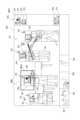
次にクロップ設定画面200について説明する。
図15はUI制御部30の制御により表示部77(又は表示部15)に表示されるクロップ設定画面200の例を示している。例えばユーザがマルチビュー画面100において或るクロップ画像の領域を操作(クリック等)することに応じて、UI制御部30はこのクロップ設定画面200を表示させる制御を行う。
このクロップ設定画面200は、ユーザに、クロップモードの操作や、マニュアルモード或いはセミオートモードの操作を実行させるための画面である。
なおマルチビュー画面100からクロップ設定画面200への遷移のトリガとなる操作は多様に考えられる。マルチビュー画面100においてクロップ設定画面200への遷移を指示するボタン表示があるようにしてもよいし、特定の態様の操作をクロップ設定画面200への遷移の指示としてもよい。<4. Crop setting screen>
Next, the
FIG. 15 shows an example of a
This
Note that various operations can be considered to trigger the transition from the
図12のクロップ設定画面200は、大きく分けて設定領域201、画像選択領域202、操作領域203が用意される。
The
設定領域201には、例えば或る1つの撮像画像としてのショットVDが表示される。仮に図12のマルチビュー画面100におけるショットVD4がショットVD1から切り出された画像であるとする。
このときにUI制御部30は、図12のショットVD4の領域がクリック等されることに応じて、もとの撮像画像であるショットVD1が、クロップ設定画面200の設定領域201に表示されるようにする。In the
At this time, the
図15のようなクロップ設定画面200において、設定領域201の画像には、画像解析による被写体認識結果に基づいて、候補枠EWが表示される。候補枠EWは、セミオートモードやオートモードでクロップ対象とされる被写体の候補を示している。
この例では、候補枠EWは、それぞれ画像内での被写体人物の領域を大まかに提示するものとされている。また候補枠EWでは、アップショット/バストショット/ウエストショット/ニーショット/全身ショットなどとしての対象となる領域を大まかに横線で区切って示している。
なお、この例では、候補枠EWは、クロップ領域自体を表すものではない。候補枠EWは、クロップ画像として切り取られる被写体人物等の候補を示すものとしている。但し、候補枠EWがクロップ領域自体を示すものとしてもよい。In the
In this example, each candidate frame EW is assumed to roughly represent the area of the subject person within the image. In the candidate frame EW, target areas for up-shots, bust shots, waist shots, knee shots, whole-body shots, etc. are roughly divided by horizontal lines.
Note that in this example, the candidate frame EW does not represent the crop area itself. The candidate frame EW is assumed to indicate a candidate for a subject person or the like to be cropped as a cropped image. However, the candidate frame EW may indicate the crop area itself.
候補枠EWは、画像解析による被写体認識結果に応じて動画のフレーム毎に設定される。従って設定領域201に動画が表示される場合、候補枠EWの位置も被写体の位置に応じてフレーム毎に変化することになる。
The candidate frame EW is set for each frame of the video according to the subject recognition result obtained by image analysis. Therefore, when a moving image is displayed in the
また設定領域201の画像には、顔認識枠240が表示される。画像解析による顔認識結果に基づいて、被写体人物の顔領域が、顔認識枠240により示される。
Further, a
また設定領域201の画像において、被写体認識の結果認識された被写体に対しては、被写体識別情報241が表示される。例えば被写体人物の近傍に「ID1」「ID2」・・・等の識別ナンバが表示される。
Further, in the image in the
また設定領域201の画像において、被写体認識の結果認識された被写体人物に対しては、その顔の向きを示す顔方向情報242が表示される。例えば被写体人物の顔の近傍に「R」「C」「L」のいずれかが表示される。「R」は右を向いていること、「C」は正面を向いていること、「L」は左を向いていることを示している。
この顔方向情報242は、いわゆる前空けモードがオンとされたときにスペースを空ける方向をユーザに提示するものとなる。Further, in the image in the
This
クロップ設定画面200における画像選択領域202には、クロップ設定可能な撮像画像が表示される。ここでは撮像画像であるショットVD1,VD2,VD3が表示されている状態としている。
ユーザは、この画像選択領域202で任意の画像を選択操作(クリック等)することで、クロップ設定の元とする撮像画像、即ち設定領域201に表示する画像を選択することができる。In the
By performing a selection operation (such as clicking) on an arbitrary image in the
クロップ設定画面200における操作領域203には、各種の操作ボタンが表示される。ここではOKボタン220、キャンセルボタン221、オートボタン222、終了ボタン223、アップ/ファーモードボタン230、前空けモードボタン231を例示している。
Various operation buttons are displayed in the
OKボタン220は、クロップ設定画面200上で行ったユーザ操作を反映させて終了する操作のための操作子である。
ユーザが各種の操作を行った後、OKボタン220を操作すると、UI制御部30は、それまでのユーザ操作による設定等が有効な状態とし必要な設定変更等を行ったうえで、マルチビュー画面100に戻るようにする。The
When the user operates the
キャンセルボタン221は、クロップ設定画面200上で行ったユーザ操作を反映させずに終了する操作のための操作子である。
ユーザが各種の操作を行った後、キャンセルボタン221を操作すると、UI制御部30は、それまでのユーザ操作による設定等を無効として、設定変更等を行わずにマルチビュー画面100に戻るようにする。The cancel
When the user operates the cancel
オートボタン222は、ユーザがクロップ処理についてオートモードを指示する操作子である。
ユーザがオートボタン222の操作を行った場合、UI制御部30は、現在の処理対象となっているクロップ画像としてのショットVDをオートモードに設定して、マルチビュー画面100に戻るようにする。現在の処理対象のクロップ画像としてのショットVDとは、例えばマルチビュー画面100においてクロップ設定画面200に移行させるためにユーザがクリック等の指定操作を行ったショットVDのこととなる。The
When the user operates the
終了ボタン223は、クロップ処理の終了を指示するための操作子である。
ユーザが終了ボタン223の操作を行った場合、UI制御部30は、現在の処理対象となっている撮像画像としてのショットVDからのクロップ画像生成を終了させてマルチビュー画面100に戻るようにする。現在の処理対象の撮像画像としてのショットVDとは、例えばマルチビュー画面100においてクロップ設定画面200に移行させるためにユーザがクリック等の指定操作を行ったショットVDを切り出している元の撮像画像のショットVD、つまり設定領域201に表示されているショットVDのこととなる。The
When the user operates the
アップ/ファーモードボタン230は、画像の寄り/引きのモードを指定する操作子である。
例えばユーザのアップ/ファーモードボタン230の操作に応じてUI制御部30は、クロップ設定対象としているクロップ画像のクロップ領域を、寄りの設定と引きの設定で切り替える。例えば顔のアップショット/全身ショットという切り替えを行う。
なお、アップショット/バストショット/ウエストショット/ニーショット/全身ショットが順次切り替えられるようにしてもよい。The up/
For example, in response to the user's operation of the up/
Note that the close-up shot/bust shot/waist shot/knee shot/full body shot may be sequentially switched.
前空けモードボタン231は、前空けモードのオン/オフを切り替えるための操作子である。
UI制御部30は前空けモードの操作に応じて、クロップ設定対象としているクロップ画像について前空けを行うか否かの設定を切り替える。
なお後に例示するが「前空け」とは、画像内で顔の前方に相当する領域を開けることである。例えば右向きの顔部分を切り取る場合、顔を画像内で左寄りにして右側を開けると、構図的に良いものとなる。ユーザは、このような前空けを行うか否かを前空けモードで選択できる。The front
The
As will be exemplified later, "opening the front" means opening an area corresponding to the front of the face in the image. For example, when cutting out a face facing to the right, the composition will be better if the face is moved to the left in the image and the right side is opened. The user can select whether or not to perform such a front opening in the front opening mode.
以上のクロップ設定画面200の例は一例であり、他に多様な表示例が想定されることはいうまでもない。
またクロップ画像のアスペクト比を選択できるようなインタフェースを用意するなど、上記以外の操作を可能としてもよい。
The above example of the
Further, operations other than those described above may be made possible, such as by providing an interface that allows selection of the aspect ratio of the cropped image.
<5.クロップ設定処理>
以下、クロップ設定画面200を用いたクロップ設定について説明していく。
まずマニュアルモードでのクロップ設定について説明する。マニュアルモードは、クロップ領域をユーザが設定領域201上で範囲指定すること設定するモードである。このマニュアルモードは、画像解析によっては被写体を認識できない場合、被写体が動かない場合、被写体の動きや移動が少ない場合などであって、特にユーザが任意にクロップ領域を設定したい場合に利用することが好適となる。マニュアルモードで設定されたクロップ領域は固定の領域となる(フレーム毎に変化しない)。<5. Crop setting process>
Crop settings using the
First, we will explain crop settings in manual mode. The manual mode is a mode in which the user specifies a range on the
ユーザは、マルチビュー画面100上で或るショットVDを選択する操作(クリック/タップ/ダブルクリック/ダブルタップ等)を行うことで、UI制御部30は表示をマルチビュー画面100からクロップ設定画面200に遷移させる。
ユーザは、クロップ設定画面200の設定領域201上において、切り出したい領域を選択する操作を行う。例えば長方形の左上、右上の座標を指定する操作を行う。When the user performs an operation (click/tap/double click/double tap, etc.) to select a certain shot VD on the
The user performs an operation to select an area to be cropped on the
図16に、例えばユーザが画面上のカーソルを、カーソルCUR1として示すように移動させてクリックするなどして位置PT1を指定する。続いてドラッグ操作によりカーソルを移動させる。このとき、ドラッグ操作に応じてクロップ枠CRWmが変化(長方形の範囲が拡大/縮小)される。ユーザが例えばドラッグ操作によりカーソルCUR2として示すように移動させ、位置PT2を指定した場合、図示するクロップ枠CRWmが、ユーザが指定するクロップ領域を示すものとなる。
その後ユーザがカーソルCUR3として示すように、OKボタンを操作した場合、UI制御部30は、以降、設定対象のショットVDについて、図示するクロップ枠CRWmに相当するクロップ領域でクロップ処理がされるように制御し、表示をマルチビュー画面100に戻す。In FIG. 16, for example, the user moves the cursor on the screen as shown as cursor CUR1 and clicks to specify position PT1. Next, move the cursor by dragging. At this time, the cropping frame CRWm is changed (the rectangular range is enlarged/reduced) in accordance with the drag operation. When the user moves the cursor CUR2 as shown by a drag operation and specifies the position PT2, the illustrated cropping frame CRWm indicates the cropping area specified by the user.
After that, when the user operates the OK button as shown by the cursor CUR3, the
なお、例えばこのようなマニュアル操作の場合、最初の位置PT1の指定は、候補枠EWに含まれない位置とされることで、UI制御部30は、それをマニュアル操作の開始のための位置指定操作と認識できる。候補枠EW内の指定は後述するセミオートモードの操作とする場合、最初の指定位置により、ユーザがマニュアル操作を行おうとしているのか、セミオートモードによる被写体指定を行ったのかを区別できる。
或いは、候補枠EWの内外位置にかかわらず、最初の座標指定からドラッグ操作が行われたことで、UI制御部30はマニュアル操作が行われていると認識し、後述のセミオートモードの被写体指定と区別するようにしてもよい。
UI制御部30がこれらの識別を行うことで、ユーザはクロップ設定画面200上で、特にマニュアルモード、セミオートモードの区別のための別途の操作を行う必要はなく、いきなりマニュアルモードの操作を行ったり、後述するセミオートモードの被写体指定操作を行うことができるようになる。For example, in the case of such a manual operation, the initial position PT1 is specified as a position not included in the candidate frame EW, and the
Alternatively, regardless of the position inside or outside of the candidate frame EW, the
Since the
なお、マニュアルモードの操作の場合に、ユーザに完全に自由にクロップ領域を設定させることは、適当ではない場合もある。
例えば、設定領域201上で非常に狭い範囲となる領域が指定された場合、クロップ画像は大幅な拡大画像となり、解像度が低下し、画像品質が落ちるものとなることがある。Note that in the case of manual mode operation, it may not be appropriate to allow the user to completely freely set the cropping area.
For example, if a very narrow area is specified on the
そこで、ユーザの操作に制限を加える。
図17は、図16と同じくユーザがドラッグ操作を行っている過程を示している。破線で示すクロップ枠CRWmYは黄色の枠表示、実線で示すクロップ枠CRWmRは赤色の枠表示であるとする。
例えばユーザがカーソルCUR5で示すように位置PT5を指定し、その後ドラッグ操作をしたとする。操作がカーソルCUR6まで進んだ状態では、クロップ枠CRWmYとして黄色の枠が表示され、これは、ユーザに、このサイズでのクロップ処理は禁止されていることを提示するものとする。
その後、指定される領域がある程度の面積以上となると、枠がクロップ枠CRWmRのように赤色になるようにする。これは、そのクロップ枠CRWmRの領域はクロップ領域として設定可能であることをユーザに提示する意味を持つ。Therefore, restrictions are placed on user operations.
Similar to FIG. 16, FIG. 17 shows a process in which the user is performing a drag operation. It is assumed that the cropping frame CRWmY indicated by a broken line is displayed as a yellow frame, and the cropping frame CRWmR indicated by a solid line is displayed as a red frame.
For example, assume that the user specifies position PT5 as indicated by cursor CUR5 and then performs a drag operation. When the operation has progressed to cursor CUR6, a yellow frame is displayed as cropping frame CRWmY, which indicates to the user that cropping at this size is prohibited.
Thereafter, when the specified area exceeds a certain area, the frame is made to turn red like the cropping frame CRWmR. This has the meaning of presenting to the user that the area of the cropping frame CRWmR can be set as a cropping area.
例えばこのように、最低限の解像度が担保されているか否かでクロップ枠CRWmの色を変え、ユーザ(オペレータ)に設定可能か否かを知らせるようにすることで、ユーザはマニュアルモードによっても適切な画質状態によるクロップ設定ができる。換言すればマニュアルモードの操作を可能としても、放送等に用いるクロップ画像の画像品質を落とさないようにすることができる。
なお、クロップ枠CRWmの色を変えることに限らない。例えば解像度条件が担保されない場合はテキスト表示で「設定不可」等が表示され、解像度条件が担保される状態となったら「OK」等の表示が行われるようにしてもよい。
もちろん、色や文字にかかわらず、他の表示態様により、設定ができない状態であるか許容される状態であるかが示されても良い。For example, by changing the color of the cropping frame CRWm depending on whether the minimum resolution is guaranteed or not, and informing the user (operator) whether the setting is possible or not, the user can also use manual mode to You can make crop settings depending on the image quality. In other words, even if manual mode operation is possible, the image quality of cropped images used for broadcasting etc. can be prevented from deteriorating.
Note that the present invention is not limited to changing the color of the cropping frame CRWm. For example, if the resolution condition is not guaranteed, a text message such as "Setting not possible" may be displayed, and when the resolution condition is guaranteed, a message such as "OK" may be displayed.
Of course, regardless of color or text, other display modes may be used to indicate whether settings are not allowed or allowed.
ところで図16や図17の例ではクロップ領域の指定として左上と右下の2点(2つの座標)をユーザが指定するものとしたが、指定のための操作手法は多様に考えられる。
例えば図18では、ユーザが画面上の1つの座標を指定する例を示している。
ユーザがカーソルCUR4で示す位置で位置PT4の指定操作を行ったとする。UI制御部30はこの操作に応じて、クロップ領域を計算し、クロップ枠CRWmを表示させる。例えばUI制御部30は、指定された座標を中心となるようにクロップ領域を計算する。或いは、例えば指定された座標が左上となるようにクロップ領域を計算することも考えられる。
このようにユーザの1つの座標点に応じてクロップ枠CRWmが表示された後に、ユーザがカーソルCUR3として示すようにOKボタン220を操作したら、UI制御部30は、以降、設定対象のショットVDについて、図示するクロップ枠CRWmに相当するクロップ領域でクロップ処理がされるように制御し、表示をマルチビュー画面100に戻す。Incidentally, in the examples shown in FIGS. 16 and 17, the user specifies two points (two coordinates) at the upper left and lower right to specify the cropping area, but there are various possible operation methods for specifying.
For example, FIG. 18 shows an example in which the user specifies one coordinate on the screen.
Assume that the user performs an operation to specify position PT4 at the position indicated by cursor CUR4. In response to this operation, the
After the cropping frame CRWm is displayed in accordance with one coordinate point of the user, if the user operates the
例えばこのように、最低限、1つの座標を指定することで、マニュアルモードの設定が可能となる。
もちろんさらに操作例は多様である。例えば図16のように2つの点を指定する場合に、ドラッグ操作ではなく、まず左上座標を指定し、その後右下座標を指定するものでもよい。もちろん右上座標と左下座標を指定してもよい。
クロップ領域の周囲をなぞるような操作(枠を描くような操作)によってクロップ領域が設定されるようにしてもよい。
いずれにしても、1以上の座標をユーザが指定することで、クロップ領域が設定されるようにすればよい。For example, by specifying at least one coordinate in this manner, manual mode can be set.
Of course, further examples of operation are diverse. For example, when specifying two points as shown in FIG. 16, instead of using a drag operation, the upper left coordinate may be specified first, and then the lower right coordinate may be specified. Of course, you may also specify the upper right and lower left coordinates.
The crop area may be set by an operation such as tracing around the crop area (an operation such as drawing a frame).
In any case, the cropping area may be set by the user specifying one or more coordinates.
続いてセミオートモードでのクロップ設定について説明する。セミオートモードは、クロップ領域をユーザが設定領域201上で被写体指定することに応じて設定するモードである。このセミオートモードは、例えば主要な被写体などとしての特定の人物等のクロップ画像の生成に好適で、被写体の動きがある(動きが大きい)場合にも自動的にクロップ領域が追従される。つまりフレーム毎に、指定された被写体にとって適切なクロップ領域となるように、クロップ領域が変動される。
Next, crop settings in semi-auto mode will be explained. The semi-auto mode is a mode in which a cropping area is set in response to the user specifying a subject on the
ユーザは、マルチビュー画面100上で或るショットVDを選択する操作(クリック/タップ/ダブルクリック/ダブルタップ等)を行うことで、UI制御部30は表示をマルチビュー画面100からクロップ設定画面200に遷移させる。
ユーザは、クロップ設定画面200の設定領域201上において、候補枠EWで示される被写体を選択する。
例えば図19には、或る被写体人物について表示されている候補枠EWの内側にカーソルCUR10を位置させ、クリック操作等を行うことで被写体を指定する例を示している。なお、この例では、候補枠EW内のどこを指定していしても、該当する被写体が選択されるものとする。即ち候補枠EW内の位置であれば、例えば被写体人物の顔の部分であってり、腰の付近などであったりしても、それらの操作の違いは無く、単純に当該被写体が指定されたものとして扱う例とする。When the user performs an operation (click/tap/double click/double tap, etc.) to select a certain shot VD on the
The user selects the subject indicated by the candidate frame EW on the
For example, FIG. 19 shows an example in which a cursor CUR10 is positioned inside a candidate frame EW displayed for a certain subject person, and the subject is specified by performing a click operation or the like. In this example, it is assumed that the corresponding subject is selected no matter where within the candidate frame EW is specified. In other words, if the position is within the candidate frame EW, there is no difference in the operation even if it is a part of the subject's face or near the waist, and the subject is simply specified. This is an example of treating it as an object.
ユーザがこのように被写体を指定する操作を行ったら、UI制御部30はこの操作に応じて、当該被写体を切り出すためのクロップ領域を計算し、クロップ枠CRWsを表示させる。例えばUI制御部30は、指定された被写体について、顔領域が中心となるようなクロップ領域を計算する。もちろんUI制御部30は、指定された被写体について、全身が入るようなクロップ領域を計算することもできる。
そしてUI制御部30は計算したクロップ領域をクロップ枠CRWsによりユーザに提示する。
ユーザの被写体指定に応じてクロップ枠CRWsが表示された後に、ユーザがカーソルCUR11して示すようにOKボタン220を操作したら、UI制御部30は、以降、設定対象のショットVDについて、指定された被写体を対象とするクロップ領域でクロップ処理がされるように制御し、表示をマルチビュー画面100に戻す。
この場合のクロップ処理は、指定された被写体の動きの追尾処理により、フレーム毎にクロップ領域が計算されることになる。従ってユーザが細かく指定しなくとも、例えば常に、指定した被写体の顔が画像の中心となるようなクロップ画像のショットVDが得られることになる。When the user performs an operation to designate a subject in this manner, the
Then, the
After the cropping frame CRWs are displayed in accordance with the user's subject specification, when the user operates the
In the cropping process in this case, a cropping area is calculated for each frame by tracking the movement of the designated subject. Therefore, even if the user does not specify details, for example, a shot VD of a cropped image in which the face of the specified subject is always at the center of the image can be obtained.
ところで、この被写体指定に応じたクロップ領域の計算は、前空けモードボタン231の操作による前空けモードのオン/オフや、アップ/ファーモードボタン230の操作に応じて行われるようにする。
By the way, calculation of the crop area according to the subject specification is performed in response to turning on/off the front opening mode by operating the front
図20Aは前空けモードのオフの場合のクロップ画像、図20Bは前空けモードのオンの場合のクロップ画像を示している。
上述のように「前空け」とは、画像内で顔の前方に相当する領域を開けることであり、顔が右向きの場合は右側を、顔が左向きの場合は左側を開けることで、バランス感のよい画像とすることができる。
前空けモードのオフのときは、例えば図20Aのように顔が中央となるようにする。即ちUI制御部30は、指定された被写体の顔領域が中心となるようにクロップ領域を計算する。
前空けモードのオンのときは、例えば図20Bのように顔が中央からずれた位置となるようにする。即ちUI制御部30は、指定された被写体の顔の向きに応じて、顔の位置をずらすようにクロップ領域を計算する。図のように顔が右向きの場合、顔が画像内で左寄りになることで、右側が開くようなクロップ領域を計算する。
図示しないが顔が左向きの場合、顔が画像内で右寄りになることで左側が開くようなクロップ領域を計算する。
顔が正面向きの場合は、UI制御部30は、前空けモードのオン/オフに限らず、顔が画像の中央に配置されるようにクロップ領域を計算する。FIG. 20A shows a cropped image when the front opening mode is off, and FIG. 20B shows a cropped image when the front opening mode is on.
As mentioned above, "opening the front" means opening up the area corresponding to the front of the face in the image.If the face is facing right, opening the right side, and if the face is facing left, opening the left side creates a sense of balance. The result can be a good image.
When the front space mode is off, the face should be centered, for example, as shown in FIG. 20A. That is, the
When the open-front mode is on, the face is positioned off-center, as shown in FIG. 20B, for example. That is, the
Although not shown, if the face is facing left, a cropping area is calculated that opens the left side by moving the face to the right in the image.
When the face is facing forward, the
このようにセミオートモードでは、クロップ画像において前空けを行うか否かをユーザが任意に選択できるようにしている。
なお、前空けモードのオン/オフは、オートモードにおいても適用されるようにすることが考えられる。つまりオートモードで被写体が自動的に特定され、クロップ領域が自動計算されるときも、このクロップ設定画面200の前空けモードのオン/オフ操作が反映されるようにする。In this way, in the semi-automatic mode, the user can arbitrarily select whether or not to perform front spacing in the cropped image.
Note that turning on/off the front space mode may also be applied in the auto mode. In other words, even when the subject is automatically specified in the auto mode and the crop area is automatically calculated, the on/off operation of the front opening mode on the
またUI制御部30は、アップ/ファーモードボタン230の操作に応じて、クロップ領域の計算は異なるようにする。
例えば初期状態ではアップが選択されているようにする。そしてアップ(寄せ)が選択されている場合は、UI制御部30は、顔を中央とし、しかも、画像内の顔が大きく写るようなクロップ領域の計算を行う。
クロップ画像を「寄り」の画像とするか「引き」の画像とするかはアップ/ファーモードボタン230の操作により切り替えられる。そしてファー(引き)が選択されている場合は、UI制御部30は、例えば被写体人物の全身が含まれるように、例えば被写体人物の腰のあたりなどを中央とし、しかも、画像内に全身が入るようなクロップ領域の計算を行う。Further, the
For example, in the initial state, up is selected. When close-up (close-up) is selected, the
Whether the cropped image is a "closer" image or a "lower" image can be switched by operating the up/
このようにセミオートモードでは、クロップ画像において寄り/引きの設定をユーザが任意に選択できるようにしている。
なお、上述のように例えばアップ/ファーモードボタン230などによりアップショット/バストショット/ウエストショット/ニーショット/全身ショットが選択できるようにし、それに応じてUI制御部30がクロップ領域の計算を行うことも当然想定される。
また寄り/引きの設定、或いはアップショット/バストショット/ウエストショット/ニーショット/全身ショットの設定は、オートモードにおいても適用されるようにすることも考えられる。つまりオートモードで被写体が自動的に特定され、クロップ領域が自動計算されるときも、このクロップ設定画面200のアップ/ファーモードボタン230の操作が反映されるようにする。
また日の丸構図、三分割構図などを選択できるようにしてもよい。In this way, in the semi-auto mode, the user can arbitrarily select the shift/pull settings for the cropped image.
Note that, as described above, for example, the up shot/bust shot/waist shot/knee shot/full body shot can be selected using the up/
It is also conceivable that the bias/pull settings or the close-up shot/bust shot/waist shot/knee shot/full body shot settings be applied in the auto mode as well. In other words, even when the subject is automatically specified and the crop area is automatically calculated in the auto mode, the operation of the up/
Furthermore, it may be possible to select a Japanese flag composition, a third division composition, or the like.
以上の前空けモードや、寄り/引きのモード(構図モードとも言える)は、より細かく設定できるようにしてもよい。
例えば図21は、クロップ設定画面200においてズームバー251、前空けバー252を表示させた例である。The above-mentioned front space mode and close/pull mode (also referred to as composition mode) may be set in more detail.
For example, FIG. 21 shows an example in which a
ズームバー251によっては、ユーザは寄り(アップ)と引き(ロング)の具合を連続的に変化させて指定することができる。例えばズームバー251のつまみ251aをスライド操作することで、ズーム位置を指定する。UI制御部30はこれのズームバー251の操作に応じて、セミオートモードやオートモードでのクロップ領域の計算を、指定されたズーム位置に相当するように行うようにする。
Depending on the
また前空けバー252によっては、ユーザは前空け量や開ける方向を連続的に変化させて指定することができる。例えば前空けバー252のつまみ252aをスライド操作することで、画像左側の前空け量、画像右側の前空け量を指定する。UI制御部30はこれの前空けバー252の操作に応じて、セミオートモードやオートモードでのクロップ領域の計算を、指定された前空け量や方向が反映されるように行う。
Further, depending on the
また、構図としてのアップショット/バストショット/ウエストショット/ニーショット/全身の選択を、候補枠EWに対する指定位置(例えばクリック位置)により行うようにする例も考えられる。
図22Aには、被写体人物に対する候補枠EWを示しているが、図示のように1つの候補枠EWは、アップショットに対応する候補枠EW1、バストショットに対応する候補枠EW2、ウエストショットに対応する候補枠EW3、ニーショットに対応する候補枠EW4、全身ショットに対応する候補枠EW5が重ねて表示されていると考えることができる。
図22Bには、これら候補枠EW1,EW2,EW3,EW4,EW5を重ねずに示している。Furthermore, an example may be considered in which the selection of a close-up shot, bust shot, waist shot, knee shot, or whole body as a composition is performed based on a specified position (for example, a click position) with respect to the candidate frame EW.
FIG. 22A shows candidate frames EW for the subject person, and as shown in the figure, one candidate frame EW corresponds to a close-up shot, a candidate frame EW1 corresponding to a bust shot, a candidate frame EW2 corresponding to a bust shot, and a waist shot. It can be considered that the candidate frame EW3 corresponding to the knee shot, the candidate frame EW4 corresponding to the knee shot, and the candidate frame EW5 corresponding to the whole body shot are displayed in an overlapping manner.
In FIG. 22B, these candidate frames EW1, EW2, EW3, EW4, and EW5 are shown without overlapping.
ここで、ユーザが候補枠EW1,EW2,EW3,EW4,EW5のいずれかを指定することで、被写体指定と寄り/引きの構図指定が同時に行われるようにする。
例えばユーザが候補枠EW1の部分を指定した場合、図23にEW1指定の画像として示すように、指定された被写体の顔のアップショットとなるようなクロップ領域の計算が行われるようにする。
同様に、ユーザが候補枠EW2の部分を指定した場合、図23にEW2指定の画像として示すように、指定された被写体のバストショットとなるようなクロップ領域の計算が行われるようにする。
ユーザが候補枠EW3の部分を指定した場合、EW3指定の画像として示すように、指定された被写体のウエストショットとなるようなクロップ領域の計算が行われるようにする。
ユーザが候補枠EW4の部分を指定した場合、EW4指定の画像として示すように、指定された被写体のニーショットとなるようなクロップ領域の計算が行われるようにする。
ユーザが候補枠EW5の部分を指定した場合、EW5指定の画像として示すように、指定された被写体の全身ショットとなるようなクロップ領域の計算が行われるようにする。
このようにすることで、アップ/ファーモードボタン230の操作を不要とし、被写体指定の操作のみで、同時に構図の設定が行えることになる。Here, by the user specifying any of the candidate frames EW1, EW2, EW3, EW4, and EW5, the subject specification and the close/close composition specification are performed at the same time.
For example, when the user specifies the candidate frame EW1, a cropping area is calculated to provide a close-up shot of the specified subject's face, as shown in FIG. 23 as an image specified by EW1.
Similarly, when the user specifies the candidate frame EW2, a cropping area is calculated to provide a bust shot of the specified subject, as shown in FIG. 23 as an image designated by EW2.
When the user specifies a portion of the candidate frame EW3, a cropping area that becomes a waist shot of the specified subject is calculated, as shown in the image specified by EW3.
When the user specifies a portion of the candidate frame EW4, a cropping area is calculated to provide a knee shot of the specified subject, as shown in the image specified by EW4.
When the user specifies a portion of the candidate frame EW5, a cropping area is calculated to provide a full body shot of the specified subject, as shown in the image specified by EW5.
By doing so, it is not necessary to operate the up/
なお、図22と図23からわかるように、候補枠EW1,EW2,EW3,EW4,EW5は、クロップ領域をそのまま示しているのではなく、例えば被写体におけるアップショット/バストショット/ウエストショット/ニーショット/全身ショットとして切り取られる縦方向の範囲を大まかに示し、幅方向は共通のサイズ(例えば被写体人物の肩幅のサイズ)としている。
これは、例えば図15のように複数の被写体について候補枠EWを示すときに、クロップ領域をそのまま表示すると、画面が煩雑になりすぎ、また各被写体の候補枠EWが重なってわかりにくくなるためである。横方向のサイズは無視した幅で候補枠EWを表示することで、クロップ設定画面200をわかりやすい画面とすることができる。Note that, as can be seen from FIGS. 22 and 23, candidate frames EW1, EW2, EW3, EW4, and EW5 do not directly indicate cropped areas, but, for example, close-up shots, bust shots, waist shots, and knee shots of the subject. /The vertical range to be cropped as a full-body shot is roughly shown, and the width direction is set to a common size (for example, the size of the subject's shoulder width).
This is because, for example, when showing candidate frames EW for multiple subjects as shown in Fig. 15, if the cropping area is displayed as is, the screen becomes too cluttered, and the candidate frames EW for each subject overlap, making it difficult to understand. be. By displaying the candidate frame EW with a width that ignores the horizontal size, the
例えば以上のようにセミオートモードでは、被写体指定の操作や、アップ/ファーモード、前空けモードの操作などが行われる。
もちろんさらに操作例は多様である。例えば以上では、候補枠EWにより被写体を指定するものとしたが、候補枠EWを表示しない例もある。
例えば図24はクロップ設定画面200において候補枠EWを表示しない例とした。ユーザは例えば被写体人物の部分を指定する(例えばカーソルCUR21)操作を行う。UI制御部30は、ユーザがクリック等した座標に被写体人物の画像が存在する場合、それを被写体指定の操作と認識し、被写体に応じたクロップ領域の計算を行い、計算されたクロップ領域を示すクロップ枠CRWsを表示させる。
このように、候補枠EWを用いなくとも被写体指定の操作を可能とすることはできる。但し、候補枠EWを表示することで、被写体指定の操作を行う位置をユーザが認識しやすく、またUI制御部30の操作認識の精度も高めることができる。For example, as described above, in the semi-auto mode, operations such as specifying a subject, up/far mode, and open front mode are performed.
Of course, further examples of operation are diverse. For example, in the above description, the subject is specified using the candidate frame EW, but there are also examples in which the candidate frame EW is not displayed.
For example, FIG. 24 is an example in which the candidate frame EW is not displayed on the
In this way, it is possible to perform a subject designation operation without using the candidate frame EW. However, by displaying the candidate frame EW, the user can easily recognize the position where the operation for specifying the subject is performed, and the accuracy of operation recognition by the
クロップ設定画面200では、図19のようにユーザが被写体(候補枠EW)を選択することに応じてクロップ枠CRWsが表示されるが、もう一度その被写体(候補枠EW)をクリック等することで、指定が解除されるようにすることが考えられる。
また事前に切り出す被写体を登録し、それを選択するという操作も可能である。例えば顔画像として選択可能な被写体を提示し、ユーザがその顔画像から被写体人物を指定する。UI制御部30は、指定された被写体を画像解析(顔識別)により画像内で特定し、その被写体を切り出すためのクロップ領域を計算するというものである。On the
It is also possible to register the subject to be cut out in advance and select it. For example, a selectable subject is presented as a face image, and the user specifies a person from the face image. The
指定された被写体が画枠の端などで、その被写体を中央等に配置するクロップ領域が生成できない場合もある。そのような場合には、被写体の色を変えるなどして、被写体選択が禁止されることをユーザに提示することも考えられる。 If the specified subject is at the edge of the image frame, it may not be possible to generate a cropping area that places the subject in the center. In such a case, it may be possible to present to the user that selection of the subject is prohibited, such as by changing the color of the subject.
また被写体選択操作は、アイコンの選択、操作時間(長押し等)に応じた操作内容の設定、タッチ操作、タップ操作等に応じた設定など、各種考えられる。
また音声による被写体指定が行われるようにしても良い。例えばユーザの支持をマイクロホンにより集音して認識し、指定された被写体を認識する。例えば「主役の女性をズームしながらバストショット」等の音声に応じて、当該指定に応じたクロップ領域の計算が行われるようにする。Various types of subject selection operations can be considered, such as selecting an icon, setting operation content according to operation time (long press, etc.), setting according to touch operation, tap operation, etc.
Alternatively, the subject may be designated by voice. For example, a user's support is collected and recognized using a microphone, and a designated subject is recognized. For example, in response to a voice such as "Zooming and bust shot of the leading lady," a cropping area is calculated in accordance with the specification.
続いてオートモードでのクロップ設定について説明する。オートモードは、ユーザの指定操作を介さずに、被写体認識及びクロップ領域設定が自動で行われるモードである。このオートモードは、被写体の重要度に差異がない場合や、重要度が動的に変わる場合に好適である。
オートモードの場合、画像解析により被写体が特定され、またその被写体のクロップ画像が得られるようにクロップ領域の計算が行われる。被写体の動きがある(動きが大きい)場合にも自動的にクロップ領域が追従される。Next, crop settings in auto mode will be explained. The auto mode is a mode in which object recognition and cropping area setting are automatically performed without the user's specified operation. This auto mode is suitable when there is no difference in the importance of subjects or when the importance changes dynamically.
In the case of auto mode, a subject is identified through image analysis, and a cropping area is calculated to obtain a cropped image of the subject. The cropping area is automatically tracked even when there is movement (a large amount of movement) of the subject.
オートモードを選択する場合、ユーザはマルチビュー画面100からクロップ設定画面200に遷移させた状態で、オートボタン222を操作する。これによりUI制御部30は、クロップ設定処理の対象としているショットVDをオートモードに設定し、以降、オートモードでクロップ画像が生成されるようにする。
When selecting the auto mode, the user operates the
このオートモードでは、クロップ領域は、マルチビュー画面100でユーザが選択可能な画像のバリエーションが増えるように生成することが望ましい。
例えば、
・重要被写体:脇役=3:1とする
・重要被写体はサイズ(寄り・引き)で別のクロップ画像を生成する
・画像内の被写体人数(1人、2人など)にバリエーションを持たせる
などが考えられる。In this auto mode, it is desirable that the cropping area be generated so that the variety of images that can be selected by the user on the
for example,
・Important subjects: Supporting characters = 3:1 ・Create different cropped images for important subjects depending on their size (closer/closer) ・Variation in the number of subjects in the image (1 person, 2 people, etc.) Conceivable.
以上、マニュアルモード、セミオートモード、オートモードに関する操作を説明したが、図25では各モードの遷移を示している。
これはマルチビュー画面100とクロップ設定画面200における操作に応じたモード遷移である。図中“FS”はクロップ設定画面200におけるマニュアル操作としてのクロップ領域指定操作を示し、“SS”はクロップ設定画面200における被写体指定操作を示すものとする。「OK」はOKボタン220の操作、「AUTO」はオートボタン222の操作、「NONE」は終了ボタン223の操作(クロップ終了指示)を示している。The operations related to manual mode, semi-auto mode, and auto mode have been described above, and FIG. 25 shows the transition of each mode.
This is a mode transition according to operations on the
或るクロップ画像が現在マニュアルモードであるときに、そのクロップ画像が対象とされたクロップ設定画面200に移行し、被写体指定操作SS及びOKボタン220の操作が行われると、該クロップ画像はセミオートモードでクロップ処理が行われることになる。
或るクロップ画像が現在マニュアルモードであるときに、そのクロップ画像が対象とされたクロップ設定画面200に移行し、オートボタン222の操作が行われると、該クロップ画像はオートモードでクロップ処理が行われることになる。
或るクロップ画像が現在マニュアルモードであるときに、そのクロップ画像が対象とされたクロップ設定画面200に移行し、終了ボタン223の操作が行われると、該クロップ画像に係るクロップ処理が終了される。When a certain cropped image is currently in manual mode, when the
When a certain cropped image is currently in the manual mode, when the
When a certain cropped image is currently in manual mode, when the
或るクロップ画像が現在セミオートモードであるときに、そのクロップ画像が対象とされたクロップ設定画面200に移行し、クロップ領域指定操作FS及びOKボタン220の操作が行われると、該クロップ画像はマニュアルモードでクロップ処理が行われることになる。
或るクロップ画像が現在セミオートモードであるときに、そのクロップ画像が対象とされたクロップ設定画面200に移行し、オートボタン222の操作が行われると、該クロップ画像はオートモードでクロップ処理が行われることになる。
或るクロップ画像が現在セミオートモードであるときに、そのクロップ画像が対象とされたクロップ設定画面200に移行し、終了ボタン223の操作が行われると、該クロップ画像に係るクロップ処理が終了される。When a certain cropped image is currently in semi-auto mode, if the
When a certain cropped image is currently in the semi-auto mode, if the
When a certain cropped image is currently in the semi-auto mode, when the screen moves to the
或るクロップ画像が現在オートモードであるときに、そのクロップ画像が対象とされたクロップ設定画面200に移行し、クロップ領域指定操作FS及びOKボタン220の操作が行われると、該クロップ画像はマニュアルモードでクロップ処理が行われることになる。
或るクロップ画像が現在オートモードであるときに、そのクロップ画像が対象とされたクロップ設定画面200に移行し、被写体指定操作SS及びOKボタン220の操作が行われると、該クロップ画像はセミオートモードでクロップ処理が行われることになる。
或るクロップ画像が現在オートモードであるときに、そのクロップ画像が対象とされたクロップ設定画面200に移行し、終了ボタン223の操作が行われると、該クロップ画像に係るクロップ処理が終了される。When a certain cropped image is currently in the auto mode, if the
When a certain cropped image is currently in the auto mode, if the
When a certain cropped image is currently in auto mode, when the
クロップ画像を指定していない状態、或いはクロップ処理が行われていない状態で、クロップ設定画面200において、クロップ領域指定操作FS及びOKボタン220の操作が行われると、そのクロップ領域についてマニュアルモードでクロップ処理が開始される。
クロップ画像を指定していない状態、或いはクロップ処理が行われていない状態で、クロップ設定画面200において、被写体指定操作SS及びOKボタン220の操作が行われると、その被写体指定に応じたセミオートモードのクロップ処理が開始される。
クロップ画像を指定していない状態、或いはクロップ処理が行われていない状態で、クロップ設定画面200において、オートボタン222の操作が行われると、オートモードのクロップ処理が開始される。If the crop area specification operation FS and the
If the subject specification operation SS and the
When the
ここまで説明したようなマルチビュー画面100、クロップ設定画面200を用い、以上のような動作遷移を伴うクロップ設定処理について具体例を説明する。
以下説明する処理例は、例えば図8の機能を備えた図7のCPU71において、主にUI制御部30の機能により行われるものとして説明する。即ち画像処理装置は、図1,図2,図3,図4のように、携帯端末2、コンピュータ装置5、スイッチャー3、クラウドスイッチャー4などにおいて実現される例とする。なお、図5のように撮像装置1に本実施の形態の画像処理装置が内蔵される場合、以下の処理は図6のカメラ信号合処理部13又はカメラ制御部18で行われるものと考えれば良い。Using the
The processing example described below will be described on the assumption that it is performed mainly by the function of the
図26、図27はCPU71(主にUI制御部30)によるクロップ設定処理を示している。なお、図26と図27のフローチャートは、「C1」「C2」の記号で示す部分で連続しているものとする。 26 and 27 show crop setting processing by the CPU 71 (mainly the UI control unit 30). It is assumed that the flowcharts in FIGS. 26 and 27 are continuous in the parts indicated by symbols "C1" and "C2."
ステップS101はCPU71がマルチビュー画面100の表示制御を行う処理を示している。
ステップS102でCPU71は、マルチビュー画面100においてユーザがクロップ設定トリガ操作を行ったか否かを監視する。ここでいうクロップ設定トリガ操作とは、或るクロップ画像をクリックしてクロップ設定画面200に遷移することを求める操作とする。
なお、この図26では、クロップ設定処理を説明するものとしており、マルチビュー画面100における他の操作については図示及び説明を省略している。Step S101 indicates a process in which the
In step S102, the
Note that in FIG. 26, crop setting processing is explained, and illustration and explanation of other operations on the
ユーザによるクロップ設定トリガ操作を検知したら、CPU71はステップS103に進み、クロップ設定画面200を表示させる制御を行う。
このクロップ設定画面200を表示させた状態でCPU71は、ステップS104でOK操作、ステップS105でキャンセル操作、ステップS106でオートモードの操作、ステップS107で終了操作を監視する。
またCPU71は、図27のステップS120でアップ/ファーモード操作、ステップS121で前空けモードの操作、ステップS122で画像選択操作、ステップS123でマニュアル指定(クロップ領域指定)操作、ステップS124で被写体指定操作を監視する。Upon detecting the crop setting trigger operation by the user, the
With this
In addition, the
ステップS104で監視するOK操作とはOKボタン220の操作である。
OKボタン220が操作された場合、CPU71はステップS104からS108に進み、それまでの操作(例えばマニュアル操作によるクロップ領域指定操作やセミオートモードのための被写体指定)を有効なものとして設定に反映する。これによりクロップモード変更やクロップ領域の変更等が行われる。そしてCPU71はステップS101に戻り、マルチビュー画面100を表示させる。The OK operation monitored in step S104 is the operation of the
If the
ステップS105で監視するキャンセル操作とはキャンセルボタン221の操作である。
キャンセルボタン221が操作された場合、CPU71はステップS105からS109に進み、それまでの操作(例えばマニュアル操作によるクロップ領域指定操作やセミオートモードにための被写体指定)を無効とし、設定変更しないものとする。そしてCPU71はステップS101に戻り、マルチビュー画面100を表示させる。The cancel operation monitored in step S105 is the operation of the cancel
If the cancel
ステップS106で監視するオートモード操作とはオートボタン222の操作である。
オートボタン222が操作された場合、CPU71はステップS106からS110に進み、クロップモードをオートモードに変更する。そしてCPU71はステップS101に戻り、マルチビュー画面100を表示させる。The auto mode operation monitored in step S106 is the operation of the
If the
ステップS107で監視する終了操作とは終了ボタン223の操作である。
終了ボタン223が操作された場合、CPU71はステップS107からS111に進み、それまでの操作に関わらず、処理対象のクロップ画像のクロップ処理を終了させる。そしてCPU71はステップS101に戻り、マルチビュー画面100を表示させる。The termination operation monitored in step S107 is the operation of the
When the
ステップS120で監視するアップ/ファーモード操作とは、アップ/ファーモードボタン230の操作である。
アップ/ファーモードボタン230が操作された場合、CPU71はステップS120からS130に進み、寄り/引きのモード設定を変更する。そしてCPU71はステップS103に戻り、クロップ設定画面200の表示を継続させる。The up/fur mode operation monitored in step S120 is the operation of the up/
When the up/
ステップS120で監視する前空けモードの操作とは、前空けモードボタン231の操作である。
前空けモードボタン231が操作された場合、CPU71はステップS121からS131に進み、前空けモード設定を変更する。そしてCPU71はステップS103に戻り、クロップ設定画面200の表示を継続させる。The front opening mode operation monitored in step S120 is the operation of the front
If the front
ステップS122で監視する画像選択操作とは、クロップ設定画面200の画像選択領域202での画像選択の操作である。ユーザは画像選択領域202でクロップ元とする画像を選択できる。画像選択操作があった場合、CPU71はステップS122からS132に進み、クロップ元とするショットVDを変更する。そしてCPU71はステップS103に戻り、クロップ設定画面200の表示を継続させる。この場合、クロップ元の変更に伴って、設定領域201の画像が今回選択されたショットVDに変更されることになる。
The image selection operation monitored in step S122 is an image selection operation in the
ステップS123で監視するマニュアル指定(クロップ領域指定)操作とは、マニュアルモードとしてのクロップ領域指定操作である。特には、例えば図16の最初の位置PT1としての座標の指定操作となる。
マニュアル操作の開始が検知されるとCPU71はステップS133に進んでマニュアル操作中の表示制御処理を行う。The manual designation (crop region designation) operation monitored in step S123 is a crop region designation operation in manual mode. In particular, this is an operation for specifying coordinates as the first position PT1 in FIG. 16, for example.
When the start of manual operation is detected, the
ステップS133の処理を図28に示す。なお、これは図16のように左上座標と右下座標を指定する操作に応じた処理例としている。 FIG. 28 shows the process of step S133. Note that this is an example of processing in response to the operation of specifying the upper left coordinate and lower right coordinate as shown in FIG.
CPU71はステップS151で、クロップ領域の左上の位置の座標を設定する。これはマニュアル操作が開始されたときの最初の指定位置PT1の座標である。
ステップS152でCPU71は、右下座標入力を監視する。例えばドラッグ操作を監視する。In step S151, the
In step S152, the
ドラッグ操作等により右下の位置が入力されることに応じて、CPU71はステップS153で、クロップ領域設定及び解像度判定を行う。
そしてステップS154では解像度条件がOKであるか否かで処理を分岐し、OKであればCPU71はステップS156において第1態様でクロップ枠CRWmを表示させる。解像度条件がOKでなければCPU71はステップS155において第2態様でクロップ枠CRWmを表示させる。
第1態様とは、例えば赤色のクロップ枠CRWmRとする。第2態様とは例えば黄色のクロップ枠CRWmYとする(図17参照)。
第1態様としては、設定可能を示すテキストやアイコン等が表示されるようにしてもよい。第2態様としては、設定不可を示すテキストやアイコン等が表示されるようにしてもよい。In response to input of the lower right position by a drag operation or the like, the
Then, in step S154, the process branches depending on whether the resolution condition is OK, and if OK, the
The first aspect is, for example, a red cropping frame CRWmR. The second aspect is, for example, a yellow cropping frame CRWmY (see FIG. 17).
As a first aspect, text, icons, etc. indicating that settings are possible may be displayed. As a second aspect, a text, an icon, or the like indicating that setting is not possible may be displayed.
このようなステップS152からS156までの処理を、右下の座標が確定されるまで繰り返す。
右下の座標が確定されるのは、例えばドラッグ操作の終了などとする。ドラッグを終了させた位置が、ユーザが指定した右下の座標とする。Such processing from steps S152 to S156 is repeated until the lower right coordinates are determined.
The lower right coordinates are determined, for example, at the end of a drag operation. The position where the drag ends is the lower right coordinate specified by the user.
従って、例えばユーザがドラッグ操作をしている間、ステップS152からS156までの処理が繰り返されることになり、図17で説明したように、解像度が十分とはならない範囲となっているときは、黄色のクロップ枠CRWmYとして、指定される範囲が明示され、一方、解像度が十分となる範囲となっているときは、赤色のクロップ枠CRWmRとして、指定される範囲が明示されることになる。 Therefore, for example, while the user is performing a drag operation, the processes from steps S152 to S156 will be repeated, and as explained in FIG. 17, if the resolution is not sufficient, the yellow The designated range is clearly shown as the cropping frame CRWmY, and if the resolution is sufficient, the designated range is clearly shown as the red cropping frame CRWmR.
入力される右下座標が確定したら、CPU71はステップS158で、左上座標と右下座標で指定された領域が、解像度条件を満たしているか否かを判定する。もし満たしていなければ、ステップS159で、今回の入力によるクロップ領域の指定は無効とする。この場合、第2態様で表示させているクロップ枠CRWmYの表示を終了させてもよい。
Once the lower right coordinates to be input are determined, the
以上の図28のように、図27のステップS133の処理を終えたら、CPU71はステップS134で、クロップ領域設定を行う。即ち上記ステップS159で入力が無効化されていなければ、マニュアル操作で指定されたクロップ領域(第1態様で表示させているクロップ枠CRWmRで示される領域)の指定操作を有効な操作とする。
そしてCPU71はステップS103に戻ってクロップ設定画面200を継続させる。As shown in FIG. 28 above, after completing the process in step S133 in FIG. 27, the
The
ここで、ステップS134でのクロップ領域設定とは、今回の操作入力を、その時点で有効操作として扱うというもので、マニュアル操作でのクロップ領域設定を最終的に確定させるものではない。
マニュアル操作で指定されたクロップ領域は、その後のOKボタン220の操作に応じて、ステップS108で設定に反映されることになる。
従って、ユーザが一旦マニュアル操作を行っても、OKボタン220の操作をする前に、何度でも設定をやり直すこともできるし、セミオートモードの被写体指定を行うこともできるし、さらにオートモードの指示に変更することもできる。Here, the cropping area setting in step S134 means that the current operation input is treated as a valid operation at that time, and does not finalize the cropping area setting by manual operation.
The cropping area specified by the manual operation will be reflected in the settings in step S108 in response to the subsequent operation of the
Therefore, even if the user performs manual operation once, before operating the
図27のステップS124で監視する被写体指定操作とは、セミオートモードのための被写体指定(例えば候補枠EWの指定)の操作である。
被写体指定操作が検知されるとCPU71はステップS136に進んでクロップ枠の表示及びクロップ領域設定の処理を行う。The subject specifying operation monitored in step S124 in FIG. 27 is an operation for specifying a subject (for example, specifying the candidate frame EW) for the semi-automatic mode.
When the subject designation operation is detected, the
このステップS136の処理を図29に示している。
CPU71はステップS141で、被写体指定の操作により指定された被写体を特定する。CPU71はステップS142で、その時点の構図情報(例えば構図設定の情報)に応じてクロップ領域の計算を行う。
ここでいう構図情報とは、アップ/ファーモードボタン230で設定されている寄り/引きの情報、或いはアップショット/バストショット/ウエストショット/ニーショット/全身ショットの別などである。また構図情報とは、前空けモードの操作による前空けのオン/オフの情報も含まれる。また他の構図情報も含まれる。
従って指定された被写体をその時点の構図に関する設定に応じて切り出すようなクロップ領域が計算される。The process of step S136 is shown in FIG.
In step S141, the
The composition information referred to here includes information on bias/pull set with the up/
Therefore, a cropping area is calculated in which the specified subject is cropped according to the composition settings at that time.
CPU71はステップS142で計算したクロップ領域を、ステップS143で、セミオートによるクリップ領域とする。
そしてCPU71はステップS144で当該クロップ領域を示すクロップ枠CRWsを画面上で表示させる。
以上の図29で示す処理のように図27のステップS136の処理を終えたら、CPU71は図26のステップS103に戻ってクロップ設定画面200を継続させる。The
Then, in step S144, the
After completing the process in step S136 in FIG. 27 as in the process shown in FIG. 29 above, the
ここで、ステップS144でのクロップ領域設定とは、今回のセミオートモードの被写体指定操作を、その時点では有効操作として扱うというもので、セミオートモードでのクロップ領域設定を最終的に確定させるものではない。この場合も、その後のOKボタン220の操作に応じて、ステップS108でセミオートモードの指定が設定に反映されることになる。
従って、ユーザが一旦セミオートモードの被写体指定操作を行っても、OKボタン220の操作をする前に、何度でも設定をやり直したり、マニュアル操作をし直したり、さらにオートモードの指示に変更することもできる。
Here, the cropping area setting in step S144 means that the current subject specification operation in semi-auto mode is treated as a valid operation at that time, and does not finalize the cropping area setting in semi-auto mode. . In this case as well, the designation of the semi-auto mode will be reflected in the settings in step S108 in response to the subsequent operation of the
Therefore, even if the user performs a subject specification operation in semi-auto mode, he or she may have to redo the settings as many times as necessary, perform manual operation again, or change the instructions to auto mode before operating the
<6.切り替え処理>
続いて主画像のスイッチングに関する画像処理装置の処理例を図30で説明する。ここでは図10のように1つのショットVDが入力され、そのショットVDから複数のクロップ画像としてのショットVDが生成される場合を想定している。<6. Switching process>
Next, a processing example of the image processing apparatus regarding main image switching will be described with reference to FIG. 30. Here, it is assumed that one shot VD is input as shown in FIG. 10, and shots VD as a plurality of cropped images are generated from the shot VD.
図30はショットVDとして供給される画像の1フレームタイミング(或いは間欠的なフレームタイミング)毎に行われる処理である。
CPU71は、ステップS201としてショットVDの1フレームの画像データを取得したら、ステップS202で被写体認識部34の機能による被写体認識処理を行う。FIG. 30 shows processing performed at each frame timing (or intermittent frame timing) of an image supplied as a shot VD.
After acquiring one frame of image data of the shot VD in step S201, the
ステップS202でCPU71はクロップ処理部36の機能によるクロップ処理を実行する。この場合、上述のように設定されたクロップモードに応じたクロップ処理を行うことになる。
In step S202, the
ステップS204でCPU71は、切り替え制御部33の機能による切り替えタイミング判定処理を行う。これは、現在、主画像MPの切り替えタイミングであるか否かを判定する処理である。
具体的には、切り替え判定は、現在の主画像MPの継続期間長や、現在選択可能なショットの内容などに応じて判定する。またユーザ操作により切り替え判定を行う場合もある。In step S204, the
Specifically, the switching determination is made according to the duration of the current main image MP, the contents of the currently selectable shots, and the like. Further, switching may be determined by user operation.
特にスイッチングモードとしては、図31に示すようにマニュアルスイッチングモードとオートスイッチングモードがある。これらのスイッチングモードはユーザ操作に応じて切り替えられる。例えばマルチビュー画面100上の操作(例えばスイッチングモード提示部の操作)により切り替えられる。
マニュアルスイッチングモードの場合、CPU71はユーザによる主画像MPの切り替えを指示する操作を監視して、ステップS205の判定を行うことになる。
オートスイッチングモードの場合、CPU71はステップS205で、画像解析結果、各ショットの画像分類、現在の主画像の継続期間長などに応じて、切り替えタイミングであるか否かを判定する。In particular, the switching modes include a manual switching mode and an auto switching mode, as shown in FIG. These switching modes can be switched according to user operations. For example, the mode can be switched by an operation on the multi-view screen 100 (for example, an operation on the switching mode presentation section).
In the case of manual switching mode, the
In the case of the auto switching mode, the
現在切り替えタイミングでなければ、CPU71はステップS205からS208に進み、現在の状態をマルチビュー画面100に反映させた状態として、1フレーム期間の処理を終える。
If it is not the current switching timing, the
或るフレームについての処理の際に、ステップS205で切り替えタイミングとなったと判定された場合、CPU71はステップS205からS206に進め、主画像MPの切り替え制御を行う。
つまりマルチビュー画面100においてそれまで次の主画像とされていたショットを主画像とするように切り替え部40を制御する。
またステップS207でCPU71は次の主画像(ネクスト画像MPN)とするショットVDを選択する。When processing a certain frame, if it is determined in step S205 that the switching timing has come, the
That is, the switching
Further, in step S207, the
そしてステップS208で、以上の切り替えの状況をマルチビュー画面100に反映させるようにする。
即ち、それまでネクスト画像MPNとして表示していたショットを、主画像MPとして表示させる。またステップS207で選択したショットを、ネクスト画像MPNとして表示させる。Then, in step S208, the above switching status is reflected on the
That is, the shot that has been displayed as the next image MPN is displayed as the main image MP. Further, the shot selected in step S207 is displayed as the next image MPN.
以上の処理をフレーム毎に継続することで、マルチビュー画面100においてスイッチングの状況が反映される。またクロップ設定画面200で設定されたクロップモードやクロップ領域が反映されたクロップ処理が行われることになる。
By continuing the above processing for each frame, the switching situation is reflected on the
ここで、ステップS207でのネクスト画像MPNの選択の手法には多様な例が考えられるが、例えば次のような選択ルールのいずれかをもしくは複数を用いると良い。 Here, various examples can be considered for the method of selecting the next image MPN in step S207, but for example, it is preferable to use one or more of the following selection rules.
・ユーザがマニュアルモード又はセミオートモードを指定したクロップ画像は、その操作直後の時点で優先的に選択する。例えば重み付けを与えたうえでの抽選などにより、当該ショットVDが選択されやすくする。
・ユーザがマニュアルモード又はセミオートモードを指定したクロップ画像は、その操作直後の時点で必ずネクスト画像MPNに選択する。
・ユーザがオートモードを指定したクロップ画像は、その操作直後の時点で優先的に選択する。例えば重み付けを与えたうえでの抽選などにより、当該ショットVDが選択されやすくする。
・ユーザがオートモードを指定したクロップ画像は、その操作直後の時点で必ずネクスト画像MPNに選択する。
以上の選択ルールによることで、ユーザがクロップ設定画面200で操作した場合には、その操作が反映されたクロップ画像が早い段階で主画像MPになりやすい(又は、主画像MPになる)ものとなる。設定を変えたショットVDは、ユーザが注目しているショットであることも多いため、操作の直後になるべく主画像MPとされることが好適となる。- A cropped image for which the user has specified manual mode or semi-automatic mode is preferentially selected immediately after the operation. For example, the shot VD is made more likely to be selected by a weighted lottery.
- A cropped image for which the user has specified manual mode or semi-automatic mode is always selected as the next image MPN immediately after the operation.
- A cropped image for which the user has specified auto mode is preferentially selected immediately after the operation. For example, the shot VD is made more likely to be selected by a weighted lottery.
- A cropped image for which the user has specified auto mode is always selected as the next image MPN immediately after the operation.
According to the above selection rules, when the user performs an operation on the
また、次のような選択ルールも考えられる。
・マニュアルモードで設定したショットVDにおいて被写体人物が写っていないときには、そのショットはネクスト画像MPNとして選択しない。
マニュアルモードの場合、クロップ領域が固定となるため、当該ショットVD内に目的の被写体が写っていない状態となることもある。そのような場合、当該ショットVDは主画像MPとしては好適でないため、他のショットがネクスト画像MPNとして選択されるようにする。Furthermore, the following selection rules may also be considered.
- If the subject person is not included in the shot VD set in manual mode, that shot is not selected as the next image MPN.
In the case of manual mode, since the cropping area is fixed, the target subject may not be included in the shot VD. In such a case, since the shot VD is not suitable as the main image MP, another shot is selected as the next image MPN.
さらに、クロップ設定には関係しないが、各ショットの画像分類によりネクスト画像MPNの選択を行うことも考えられる。この場合、次の選択ルールを用いる。
・「現在の主画像のショットと同一又は同等のショット」をネクスト画像MPNとして選択しない
・「現在の主画像が脇役ショットの場合、主画像のショットと同一被写体のショット」をネクスト画像MPNとして選択しない
・「現在の主画像が全体ショットで他に主役ショットがある場合の脇役ショット」をネクスト画像MPNとして選択しない
・「現在の主画像が脇役ショットで他に主役ショットがある場合の脇役ショット」をネクスト画像MPNとして選択しない
・「話者ショットがある場合の話者ショット以外のショット」をネクスト画像MPNとして選択しない
このような選択ルールを用いることで、撮像シーンの内容的に適切な自動スイッチングが行われる確率を高めることができる。Furthermore, although not related to crop settings, it is also conceivable to select the next image MPN based on image classification of each shot. In this case, the following selection rule is used.
- Do not select "a shot that is the same as or equivalent to the current main image shot" as the next image MPN - "If the current main image is a supporting character shot, select a shot of the same subject as the main image shot" as the next image MPN Do not select "Supporting shot when the current main image is a whole shot and there are other main shots" as the next image MPN. - "Supporting shot when the current main image is a supporting shot and there are other main shots" is not selected as the next image MPN. ・Do not select "shots other than the speaker shot when there is a speaker shot" as the next image MPN. By using such selection rules, automatic switching is performed that is appropriate for the content of the captured scene. can increase the probability that this will occur.
また選択ルールや画像分類は多様に考えられるし、判定可能な選択ルールや判定する画像分類のそれぞれをユーザがオン/オフできるようにしてもよい。
例えば話者ショットの検出をオフとしたり、話者ショットに関する選択ルールをオフにすることを可能にしてもよい。
また例えば主役ショットの検出をオフとしたり、主役ショットに関する選択ルールをオフにすることを可能にしてもよい。
また例えば主要被写体ショットの検出をオフとしたり、主要被写体ショットに関する選択ルールをオフにすることを可能にしてもよい。
また例えば脇役ショットの検出をオフとしたり、脇役ショットに関する選択ルールをオフにすることを可能にしてもよい。
ユーザがこれらの選択をできるようにすることで、そのときの動画コンテンツ制作意図に沿った自動スイッチングが行われるように調整できる。Further, various selection rules and image classifications can be considered, and the user may be able to turn on/off each of the selection rules that can be judged and the image classifications to be judged.
For example, it may be possible to turn off detection of speaker shots or to turn off selection rules regarding speaker shots.
Further, for example, it may be possible to turn off the detection of the main shot or to turn off the selection rule regarding the main shot.
Further, for example, it may be possible to turn off the detection of the main subject shot or to turn off the selection rule regarding the main subject shot.
Further, for example, it may be possible to turn off detection of supporting character shots or to turn off selection rules regarding supporting character shots.
By allowing the user to make these selections, adjustments can be made so that automatic switching is performed in accordance with the intention of creating video content at that time.
なお、以上では、ネクスト画像MPNの選択としたが、それまでのネクスト画像MPNを無視して、即時に主画像MPとするショットを選択して、切り替えるようにすることも考えられる。その場合にも、上記選択ルールのいずれかを適用することで、クロップ設定画面200で操作したクロップ画像が直後に主画像MPとなりやすい(或いは必ず主画像MPとなる)ようにすることができる。
Although the next image MPN has been selected in the above description, it is also possible to ignore the previous next image MPN and immediately select a shot to be the main image MP for switching. Even in that case, by applying any of the selection rules described above, it is possible to make it possible for the cropped image operated on the
またオートスイッチングモードの場合も、ユーザ操作のスイッチング指示を受け付けることも好適である。例えば突発的に見せたい場面が生じた場合に、ユーザが該当のショットVDを主画像にできるようにするとよい。
ユーザの操作はマルチビュー画面100上で行うことができるようにしたり、或いは音声入力による指示で行うことができるようにすることなどが考えられる。
Also in the auto switching mode, it is also preferable to accept switching instructions operated by the user. For example, when a scene that the user wants to see suddenly occurs, it is preferable to allow the user to set the relevant shot VD as the main image.
It is conceivable that the user's operations can be performed on the
<7.まとめ及び変形例>
以上の実施の形態によれば次の効果が得られる。
実施の形態の画像処理装置は、撮像画像の一部の領域を切り出すクロップ処理部36(切り出し処理部)と、UI制御部30を備えている。UI制御部30は撮像画像を表示する撮像画像表示領域と、クロップ処理部36で切り出されたクロップ画像を表示するクロップ画像表示領域とを含むマルチビュー画面100(第1画面)の表示制御処理を行う。またUI制御部30は、表示をマルチビュー画面100から、撮像画像からのクロップ領域を設定するクロップ設定画面200(第2画面)へ遷移させる表示制御処理を行う。またUI制御部30は、クロップ設定画面200においてクロップ領域に関する少なくとも1つの座標を指定するマニュアルモード操作(第1のユーザ操作)及びクロップ領域に関する被写体を指定するセミオートモードの被写体指定操作(第2のユーザ操作)を受け付ける処理を行う。そしてUI制御部30は、マニュアルモード操作又はセミオートモードの被写体指定操作に基づいてクロップ領域を設定する処理を行う。<7. Summary and modifications>
According to the above embodiment, the following effects can be obtained.
The image processing device according to the embodiment includes a crop processing unit 36 (crop processing unit) that cuts out a partial area of a captured image, and a
即ちマルチビュー画面100では、撮像画像やクロップ画像を表示するとともにスイッチング状況を提示し、クロップ設定画面200ではクロップ領域やクロップモードの指定が可能なユーザインタフェースを提供する。
ユーザ(オペレータ)はマルチビュー画面100(第1画面)により、スイッチング可能な入力画像として、撮像画像とクロップ画像をまとめて確認できる。
またユーザはクロップ設定画面200(第2画面)によりクロップ領域を設定することができる。これにより、状況にあわせて容易にスイッチングやクロップ領域設定を行うことができるようになる。That is, the
The user (operator) can check the captured image and the cropped image together as switchable input images using the multi-view screen 100 (first screen).
Further, the user can set a crop area using the crop setting screen 200 (second screen). This makes it possible to easily perform switching and crop area settings according to the situation.
特にクロップ領域設定は、同じクロップ設定画面200においてマニュアル操作でクロップ領域設定を行ったり、セミオートモードの被写体指定を行ったりすることを、任意に実行できる。つまりマニュアルモードの操作とセミオートモードの操作のうち、そのときにユーザにとって便利な操作を直感的に選ぶことができるため操作性が向上される。
これは、特に操作のためのモード切り替え操作を行う必要がないものとすることで、一層有効である。
例えばクロップ設定画面200では候補枠EWが表示される。候補枠EW内をクリック操作等で指定すれば、セミオートモードでクロップ領域(クロップ枠CRWsで示される範囲)が計算され、一方候補枠EWの外の指定は、マニュアル操作でのクロップ領域の左上座標の指定操作と認識するようにする。或いはクリックのみの操作をセミオートモードの被写体指定、ドラッグ操作をマニュアルモードの操作と認識してもよい。
これによりユーザはマニュアルモードとセミオートモードの操作の切り替えのための操作をする必要はない。従って常に、その時々で便利な設定手法を選択し、ワンタッチ操作でクロップ領域設定が可能となる。
特にライブ放送中などで迅速に操作しなければならない場合、このような操作性は極めて望ましいものとなる。
なお図24のように候補枠EWを表示させない場合でも、ユーザが指定した座標が例えば人物などとして認識される被写体内であればセミオートモード操作、被写体外であればマニュアル操作と認識することで、ユーザのモード切り替え操作は不要とすることができる。In particular, the crop area setting can be arbitrarily performed by manually operating the crop area setting on the same
This is even more effective because it eliminates the need to perform a mode switching operation for operation.
For example, on the
This eliminates the need for the user to perform any operation to switch between manual mode and semi-automatic mode operation. Therefore, you can always select a convenient setting method at any time and set the cropping area with a one-touch operation.
This kind of operability is extremely desirable, especially when quick operations are required, such as during live broadcasts.
Note that even when the candidate frame EW is not displayed as shown in FIG. 24, if the coordinates specified by the user are within a subject recognized as a person, it is recognized as a semi-auto mode operation, and if it is outside the subject, it is recognized as a manual operation. The user's mode switching operation can be made unnecessary.
実施の形態の画像処理装置のUI制御部30は、クロップ設定画面200においてクロップ元となる画像を表示させるとともに、クロップ元となる画像上でマニュアルモード操作を受け付けることに応じて、そのマニュアルモード操作で指定されるクロップ領域を示すクロップ枠CRWmの表示を実行させる
即ちユーザはクロップ設定画面200によりマニュアル操作でクロップ領域設定を行うことができるが、この場合、クロップ元の画像上で操作を行うことで図16,図18のようにクロップ枠CRWmを視認しながら指定できる。これにより、実際のクロップ元の画像上で被写体を確認しながら適切なクロップ領域を設定できる。
撮像画像の被写体内容は常に変化しているため、このような現時点の画像上でクロップ枠CRWmを視認できることは、クロップ画像を生成するためのクロップ領域設定に極めて好適となる。
図16の例の場合はドラッグ操作により、ユーザは範囲をフレキシブルに考えながらクロップ領域設定操作ができる。
図18の例の場合は、中心となる座標を指定するのみで良いため、クロップ領域設定操作が迅速かつ簡単に可能となる。
これ以外にもマニュアル操作手法は多様である。例えばタッチパネル上のピンチアウト、ピンチイン操作などにより、クロップ枠CRWmを拡大、縮小していくような操作も考えられる。
なおクロップ領域表示としてはクロップ領域を示す表示であればよく、クロップ枠CRWmに限らない。例えばクロップ領域をハイライトさせたり、色を変えた表示など、クロップ領域が視認できるようにする表示であればよい。The
Since the subject content of a captured image is constantly changing, being able to visually recognize the cropping frame CRWm on such a current image is extremely suitable for setting a cropping area for generating a cropped image.
In the example shown in FIG. 16, the user can set the crop area while flexibly considering the range by dragging.
In the case of the example shown in FIG. 18, it is only necessary to specify the center coordinates, so that the cropping area setting operation can be performed quickly and easily.
In addition to this, there are various manual operation methods. For example, an operation such as enlarging or reducing the cropping frame CRWm by pinch-out or pinch-in operations on the touch panel may be considered.
Note that the crop area display may be any display indicating the crop area, and is not limited to the crop frame CRWm. For example, any display that makes the cropped area visible may be used, such as highlighting the cropped area or changing the color.
実施の形態では、マニュアルモード操作に応じたクロップ領域が、クロップ画像の解像度条件を満たさないものとなる場合と、クロップ画像の解像度条件を満たすものとなる場合とで、クロップ領域表示を異なる表示態様で表示させる例を挙げた(図17参照)。
これによりユーザはクロップ設定画面200でのマニュアル操作でクロップ領域設定を行う際に、そのクロップ領域設定が適切な範囲であるか否かを認識することができる。
例えば図28の処理により、図17で説明したドラッグ操作の過程で、クロップ枠CRWが、解像度が不足する範囲となる時点では黄色表示(クロップ枠CRWy)、解像度が十分となる範囲となったら赤色表示(クロップ枠CRWr)などとする。この表示を見ながら操作できることで、マニュアル操作によっても画質を低下させないクロップ領域を設定できることになる。In the embodiment, the cropped area is displayed in different display modes depending on whether the cropped area corresponding to the manual mode operation does not satisfy the cropped image resolution condition or the cropped area which satisfies the cropped image resolution condition. An example of displaying the information is given (see FIG. 17).
Thereby, when the user manually sets the crop area on the
For example, in the process of the drag operation explained in FIG. 17, by the processing in FIG. 28, the cropping frame CRW is displayed in yellow (cropping frame CRWy) when the resolution is insufficient, and in red when the resolution is sufficient. display (cropping frame CRWr), etc. By being able to operate while viewing this display, it is possible to set a cropping area without degrading the image quality even by manual operation.
クロップ領域が解像度条件を満たさないときのクロップ領域表示とクロップ領域が解像度条件を満たすときのクロップ領域表示とでの異なる表示態様の表示とは、クロップ領域表示の色又は輝度が異なる表示態様、クロップ領域表示の種別が異なる表示態様、付加画像が異なる表示態様の、少なくとも1つに該当する表示とする。
クロップ領域表示の色又は輝度とは、クロップ領域表示としての枠線や領域の色や輝度である。
クロップ領域表示の種別は、例えばクロップ領域画像としての枠線についての太線、細線の種別や、実線、破線、点線、一点鎖線、二重線などの種別である。また例えばクロップ領域表示としての領域についてのシャドー、ハッチング、モノクロ/カラー、点描などの画像種別などである。
付加画像とはテキストやアイコン、記号などであり、付加画像が異なる表示態様とは、解像度条件を満たしているか否かを示すテキスト内容やアイコン等の表示、もしくは解像度条件を満たす場合のみの表示、もしくは解像度条件を満たしていない場合の表示などである。
例えばこれらの表示によりユーザは、マニュアル操作で設定しているクロップ領域(クロップ枠CRWm)が適切な範囲であるか否かを認識することができ、操作のガイドとすることができる。Displaying different display modes between the cropping area display when the cropping area does not satisfy the resolution condition and the cropping area display when the cropping area satisfies the resolution condition refers to display modes in which the color or brightness of the cropping area display is different, The display corresponds to at least one of a display mode in which the type of area display is different and a display mode in which additional images are different.
The color or brightness of the crop area display is the color or brightness of the frame line or area as the crop area display.
The types of crop area display include, for example, types of frame lines as crop area images, such as thick lines, thin lines, solid lines, broken lines, dotted lines, dashed lines, double lines, and the like. Also, for example, the image type such as shadow, hatching, monochrome/color, pointillist, etc. for the area to be displayed as a crop area is included.
Additional images are text, icons, symbols, etc., and the different display modes of additional images include displaying text content and icons that indicate whether or not the resolution conditions are met, or displaying only when the resolution conditions are met, Or it may be displayed when the resolution conditions are not met.
For example, these displays allow the user to recognize whether the cropping area (cropping frame CRWm) set manually is within an appropriate range, and can be used as a guide for the operation.
実施の形態では、UI制御部30は、クロップ設定画面200においてクロップ元の画像を表示させるとともに、クロップ元の画像上でセミオートモードの被写体指定操作を受け付けることに応じて、該ユーザ操作で指定された被写体を含むクロップ領域を設定するものとした。
ユーザはクロップ設定画面200によりセミオートモードでクロップ領域設定を行うことができる。この場合、クロップ元の画像上で被写体を指定する。これにより当該被写体を含むようなクロップ領域(クロップ枠CRWsの範囲)が自動的に計算される。
即ちユーザはクロップ領域を具体的に指定する操作を行う必要は無い。従ってユーザが特定の被写体のクロップ画像を欲した場合に、非常に容易な操作でクロップ領域設定が可能となる。In the embodiment, the
The user can set a crop area in semi-automatic mode using the
That is, the user does not need to perform an operation to specifically designate the cropping area. Therefore, when the user desires a cropped image of a specific subject, the cropping area can be set with a very easy operation.
実施の形態のUI制御部30は、セミオートモードの被写体指定操作を受け付けることに応じて、該ユーザ操作で指定された被写体を含むクロップ領域を示すクロップ領域表示(例えばクロップ枠CRWs)を実行させるものとした。
これによりユーザはクロップ設定画面200で、セミオートモードによるクロップ領域設定の指示を行った際に、設定されるクロップ領域をクロップ枠CRWsにより確認することができる(図19参照)。従って適切なクロップ枠CRWsであればそのクロップ領域の設定を有効とし、適切と思わなければ設定操作をし直せば良い。
この場合もクロップ領域表示とは、クロップ領域を示す表示を指し、クロップ領域を示す枠の表示や、クロップ領域をハイライトさせたり、色を変えた表示など、クロップ領域が視認できるようにする表示である。In response to receiving a subject specifying operation in semi-auto mode, the
As a result, when the user instructs to set a crop area in semi-auto mode on the
In this case as well, cropping area display refers to the display that shows the cropping area, and displays that make the cropping area visible, such as displaying a frame indicating the cropping area, highlighting the cropping area, or displaying it in a different color. It is.
実施の形態のUI制御部30は、セミオートモードの被写体指定操作で指定された被写体を含むクロップ領域を設定する際に、構図情報の選択状態に応じてクロップ領域を計算する例を挙げた。
即ち図29のステップS142において寄り/引きのモード、前空けモード等に応じてクロップ枠CRWsが計算されるとした。従ってユーザは構図情報を選択しておくことで、セミオートであってもユーザの望むクロップ領域が設定されやすくなる。つまり構図情報を適切に操作することで、セミオートモードでもユーザによって満足のいくクロップ領域設定が可能となる。
構図情報としては前空けモードと寄り/引きのモードを例に挙げたが、さらに多様な構図情報を操作可能としてもよい。
例えばアップショット/バストショット/ウエストショット/ニーショット/全身ショットなどの種別を選択できるようにしたり、日の丸構図、三分割構図などを選択できるようにしたり、ズーム状態を寄り細かく設定できるようにしたりすることが考えられる。ステップS142では、これらの構図情報を反映したクロップ領域計算が行われれば良い。An example has been given in which the
That is, in step S142 of FIG. 29, the cropping frame CRWs is calculated according to the shift/pull mode, front spacing mode, etc. Therefore, by selecting the composition information in advance, the user can easily set the desired cropping area even in semi-automatic mode. In other words, by appropriately manipulating the composition information, it is possible for the user to set a cropping area that satisfies the user even in semi-auto mode.
Although the front opening mode and the closer/pull mode have been cited as examples of composition information, a variety of other composition information may also be operable.
For example, it will be possible to select types such as close-up shots, bust shots, waist shots, knee shots, and full-body shots, it will be possible to select Hinomaru compositions, third-part compositions, etc., and the zoom state can be set in more detail. It is possible that In step S142, cropping area calculation that reflects this composition information may be performed.
実施の形態のUI制御部30は、クロップ設定画面200において被写体について構図に関する情報を表示させるものとした。
例えば図15などに示したようにクロップ設定画面200において各被写体人物に関して、顔方向情報242を表示している。これは前空けを行う方向として、左、右、正面(前空けを行わない)ことを示す情報である。これにより、ユーザはセミオートモードでクロップ領域が設定される場合の構図を予測することができる。これはセミオートモードを用いるか否かの判断にも有用となる。
構図に関する情報としては、各被写体に対応して、構図情報として寄り/引きモードの情報や、前空けモードのオン/オフの情報や、構図の種別の情報などを表示させてもよい。また、寄り/引きの程度の情報、前空け量の情報などを表示させてもよい。アップ/バストショット/ウエストショット/ニーショット/全身などの情報を表示させてもよい。つまりセミオートモードでクロップ領域を設定する場合に、どのような構図となるかをユーザが予測できるような情報であればよく、表示させる「構図に関する情報」としては各種考えられる。The
For example, as shown in FIG. 15,
As the information regarding the composition, information on the close/pull mode, information on the on/off of the open front mode, information on the type of composition, etc. may be displayed for each subject. Further, information on the degree of shift/pull, information on the amount of space in front, etc. may be displayed. Information such as close-up/bust shot/waist shot/knee shot/full body may also be displayed. In other words, any information that allows the user to predict what kind of composition will be obtained when setting a cropping area in semi-auto mode is sufficient, and various types of "composition-related information" can be considered to be displayed.
実施の形態のUI制御部30は、クロップ設定画面200においてクロップ画像の候補となる被写体毎にクロップの候補であることを示す候補枠EWを表示させるとともに、候補枠EWの指定操作をセミオートモードの被写体指定操作として受け付けるものとした。
ユーザはクロップ設定画面200によりセミオートモードでクロップ領域設定を行うことができるが、この場合、クロップ元の画像上で被写体に対して候補枠EWが表示される。この候補枠EWにより、ユーザは、セミオートモードでクロップ領域を設定できる被写体を認識することができる。つまりユーザは、候補枠EWを指定する操作を行うことでセミオートモードでの操作を行うことができ、わかりやすい操作となる。
換言すれば、候補枠EWが表示されていない被写体は、被写体認識で認識された対象、例えば人物等には該当しない被写体である。つまりセミオートモードによるクロップ領域設定の対象外の被写体でもある。そのため候補枠EWは、それが表示されていない被写体をユーザが無駄に指定操作をしてしまわないような表示としても機能する。The
The user can set the crop area in semi-automatic mode using the
In other words, a subject for which the candidate frame EW is not displayed is a subject that does not correspond to an object recognized by subject recognition, such as a person. In other words, it is also a subject that is not subject to cropping area settings in semi-auto mode. Therefore, the candidate frame EW also functions as a display that prevents the user from wastefully specifying an object for which the candidate frame EW is not displayed.
実施の形態では、UI制御部30が候補枠EWを構図毎に区分して表示させ、候補枠EWの区分に対する指定操作により、構図の指定も受け付ける例を挙げた。
例えば候補枠EWを、アップショット/バストショット/ウエストショット/ニーショット/全身ショットで区分して表示し(候補枠EW1,EW2,EW3,EW4,EW5)、指定位置により、構図指定も行われるようにした(図21、図22参照)。
これにより被写体指定と構図指定が1つの指定操作で実行できる。従ってユーザが被写体とともに構図を選択したい場合にも1回の指定操作で可能となり、非常に便利な操作となる。In the embodiment, an example has been given in which the
For example, candidate frames EW are displayed divided into up-shots, bust shots, waist shots, knee shots, and full-body shots (candidate frames EW1, EW2, EW3, EW4, EW5), and the composition can also be specified based on the specified position. (See Figures 21 and 22).
This makes it possible to designate the subject and the composition with a single designation operation. Therefore, even if the user wants to select the composition along with the subject, this can be done with a single designation operation, which is a very convenient operation.
実施の形態のUI制御部30は、クロップ設定画面200において、クロップ領域設定の対象となっているクロップ元の画像とともに、クロップ領域設定の対象となっていないがクロップ元となり得る撮像画像を表示させるものとした。
例えば図15等で説明したように、画像選択領域202で撮像画像であるショットVD1,VD2,VD3が表示される。撮像画像VD2,VD3は、現在はクロップ領域設定の対象(クロップ元)となっていないがクロップ元となり得る撮像画像である。
これらも表示することで、ユーザは他の撮像画像も確認できる。そしてクロップ元の撮像画像を任意に変更することも可能とすることで、より迅速に望むクロップ領域設定が可能となる。The
For example, as described with reference to FIG. 15 and the like, shots VD1, VD2, and VD3, which are captured images, are displayed in the
By displaying these as well, the user can also check other captured images. Furthermore, by making it possible to arbitrarily change the captured image that is the source of cropping, it becomes possible to more quickly set the desired cropping area.
実施の形態のUI制御部30は、クロップ設定画面200においてクロップ領域のオートモードを選択可能とする表示、及び自オートモード操作の受け付けを行うものとした。
例えば図15等で説明したように、オートボタン222を操作することで、クロップ領域設定がオートモードとなる(図25参照)。これにより、ユーザはマニュアル操作、セミオートモードでの操作に加え、オートモードの指定を、状況に応じて容易に使い分けることができる。
オートモードにおいては、クロップ処理部36は、他のショットVD(クロップ画像や撮像画像)を解析して、重複がないように適時クロップ領域を変更していくことが行われるようにすることで、有効なクロップ画像が生成される。The
For example, as described in FIG. 15 and the like, by operating the
In the auto mode, the
実施の形態の画像処理装置は、主画像MPを、撮像画像及びクロップ画像を含む複数のショットVDのうちで選択されたショットVDに切り替える切り替え制御部33を備え、UI制御部30はマルチビュー画面100において、主画像MPと次に主画像とされるネクスト画像MPNとが異なる表示態様で表示されるようにする例を挙げた。
例えば図13,図14で説明したように、マルチビュー画面100では、主画像提示部101とネクスト提示部102の表示態様を異なるものとする。例えば枠の色や種別を異なるものとする。
これによりユーザは主画像及び次の主画像を容易に認識できる。
なお異なる表示態様としては、主画像提示部101とネクスト提示部102の領域の色、背景色、輝度、画像種別(モノクロ/カラーなど)、領域のサイズなどを異なるものとしてもよい。つまり区別できる表示態様であればよい。The image processing device of the embodiment includes a switching
For example, as described with reference to FIGS. 13 and 14, in the
This allows the user to easily recognize the main image and the next main image.
Note that as different display modes, the color, background color, brightness, image type (monochrome/color, etc.) of the area of the main
実施の形態のUI制御部30は、マルチビュー画面100において表示するクロップ画像について、マニュアルモード操作によりクロップ領域設定がされたものであるか、セミオートモードの被写体指定操作によりクロップ領域設定がされたものであるかを示す表示を実行させるものとした。
例えば図12で説明したように、クロップモード提示部106により、各クロップ画像としてのショットVDについては、クロップ領域設定がセミオートモードで行われたかマニュアルモードで行われたかが提示される。ユーザはこれを確認し、状況に応じてクロップ領域設定モードの適否を判断し、必要に応じてモード変更を行うことができる。The
For example, as described with reference to FIG. 12, the crop
実施の形態のUI制御部30は、マルチビュー画面100において表示するクロップ画像について、オートモードが選択されてクロップ領域設定がされたものであることの表示を実行させるものとした。
例えば図12で説明したように、クロップモード提示部106により、クロップ領域設定がオートモードで行われたショットVDについてはオートモードであることが提示される。ユーザはこれを確認し、状況に応じてオートモードであることの適否を判断し、必要に応じてモード変更を行うことができる。
なお、マニュアルモード、セミオートモード、オートモードにより、各クロップ画像の枠や領域の表示態様を異なるものとしてもよい。例えば色、輝度、枠種別などを異なるものとする。The
For example, as described with reference to FIG. 12, the crop
Note that the display mode of the frame and area of each cropped image may be different depending on the manual mode, semi-auto mode, and auto mode. For example, the colors, brightness, frame types, etc. may be different.
実施の形態の切り替え制御部33は、自動スイッチングモードとされることで、切り替えタイミング判定に応じて自動的に主画像の切り替えを行う例を挙げた。
主画像MPのスイッチングも例えば手動だけでなく自動切り替え処理によっても実行されるようにする。
例えば図30の処理で切り替えタイミングが判定される。例えば主要な被写体の認識や現在の主画像の経過時間などに応じて切り替えタイミングが判定される。そしてそれに応じて主画像の切り替えが行われることで、ユーザ(オペレータ)の操作負担を生じさせずに、内容的に自然であり高品質で面白みのある放送、配信、記録等のためのコンテンツ制作を行うことができる。An example has been given in which the
Switching of the main image MP is also performed, for example, not only manually but also by automatic switching processing.
For example, the switching timing is determined in the process shown in FIG. For example, the switching timing is determined based on the recognition of the main subject, the elapsed time of the current main image, and the like. By switching the main image accordingly, you can create natural, high-quality, and interesting content for broadcasting, distribution, recording, etc. without putting any operational burden on the user (operator). It can be performed.
実施の形態では、切り替え制御部33によって主画像MPの切り替えが行われることに応じて、次の主画像とされるネクスト画像MPNの選択処理が行われるとともに、UI制御部30は、マルチビュー画面100において、切り替えにより主画像MPとされた画像及び選択処理により次の主画像とされた画像の表示を実行させるものとした。
例えば図31で説明したように、切り替え処理において、主画像が切り替えられるとともに、次の主画像であるネクスト画像MPNの選択が行われる(S206,S207)。
これに応じてマルチビュー画面100でも表示が更新される(S208)。これにより、ユーザは主画像の切り替えを認識できるとともに、次のタイミングで切り替えられる予定の画像を確認できる。In the embodiment, in response to the main image MP being switched by the switching
For example, as described with reference to FIG. 31, in the switching process, the main image is switched and the next image MPN, which is the next main image, is selected (S206, S207).
Accordingly, the display on the
実施の形態では、ネクスト画像MPN(又は主画像MP)の選択処理では、クロップ設定画面200においてクロップ領域設定がされたクロップ画像が、他の画像よりも優先度を高くした選択処理が行われることを述べた。
例えばクロップ設定画面200でクロップ領域に関する操作が行われた画像は、次に主画面として選択されやすくなるようにする。
図30で説明したように主画像が切り替えられるとともにネクスト画像MPNの選択が行われるが(S206,S207)、このとき、選択はランダムではなく重み付けがされるようにする。即ち直前にクロップ設定画面200でクロップ領域に関する操作(モード変更やクロップ領域設定など)がなされた画像が、次の主画像とされるように、重み付けをして選択処理を行う。或いは、そのような画像を必ず選択するものとする。
ユーザがクロップ設定画面200で操作した画像は、現在、ユーザが重要と考えるショットで或る可能性が高い。そこで、なるべく早く主画像として反映されるようにする。これにより放送等として、より望ましいスイッチングがなされる。In the embodiment, in the next image MPN (or main image MP) selection process, a selection process is performed in which a cropped image for which a crop area has been set on the
For example, an image for which an operation related to a crop area has been performed on the
As described with reference to FIG. 30, the main image is switched and the next image MPN is selected (S206, S207), but at this time, the selection is not random but weighted. That is, the selection processing is weighted so that the image on which an operation regarding the crop area (mode change, crop area setting, etc.) has been performed on the
The image operated by the user on the
実施の形態の処理の変形例はさらに多様に考えられる。
本開示の画像処理装置は、クロップ処理を行う機器とは別体の機器として、マルチビュー画面100やクロップ設定画面200を表示してクロップやスイッチングの状況を示したり、ユーザ操作に応じたクロップ領域設定を行うUI制御部を備えるものでもよい。Further various variations of the processing of the embodiment can be considered.
The image processing device of the present disclosure is a device that is separate from a device that performs cropping processing, and displays a
主画像MPのスイッチングに関しては、画面分割して複数のショットVDを主画像MPとする場合を加えても良いし、その場合に主画像MPとして選択する複数のショットVD(ネクスト画像MPNとするショット)を実施の形態の選択ルールに沿って選択することも考えられる。 Regarding switching of the main image MP, it is also possible to split the screen and use multiple shots VD as the main image MP, or in that case, multiple shots VD selected as the main image MP (shots selected as the next image MPN) ) may be selected according to the selection rules of the embodiment.
実施の形態のプログラムは、図26,図27,図28,図29のクロップ設定処理や、図30の切り替え処理、或いはこれらの変形例に相当する処理を、例えばCPU、DSP等、或いはこれらを含むデバイスに実行させるプログラムである。 The program of the embodiment performs the crop setting processing shown in FIGS. 26, 27, 28, and 29, the switching processing shown in FIG. This is a program that is executed by the device that contains it.
即ち実施の形態のプログラムは、撮像画像の一部の領域を切り出すクロップ処理(画像クロップ処理)と、撮像画像を表示する撮像画像表示領域とクロップ処理で切り出されたクロップ画像を表示するクロップ画像表示領域とを含むマルチビュー画面100(第1画面)の表示制御処理と、表示をマルチビュー画面100から、撮像画像からのクロップ領域を設定するクロップ設定画面200(第2画面)へ遷移させる表示制御処理と、クロップ設定画面200においてクロップ領域に関する少なくとも1つの座標を指定する第1のユーザ操作及びクロップ領域に関する被写体を指定する第2のユーザ操作を受け付ける処理と、第1のユーザ操作又は第2のユーザ操作に基づいてクロップ領域を設定する処理と、を情報処理装置に実行させるプログラムである。
このようなプログラムにより、上述した画像処理装置を、例えば携帯端末2、スイッチャー3、クラウドスイッチャー4、コンピュータ装置5、撮像装置1などの機器において実現できる。That is, the program of the embodiment includes cropping processing (image cropping processing) that cuts out a part of a captured image, a captured image display area that displays the captured image, and a cropped image display that displays the cropped image cut out by the cropping processing. display control processing of the multi-view screen 100 (first screen) including the area, and display control for transitioning the display from the
With such a program, the above-described image processing device can be realized in devices such as the
このようなプログラムはコンピュータ装置等の機器に内蔵されている記録媒体としてのHDDや、CPUを有するマイクロコンピュータ内のROM等に予め記録しておくことができる。
あるいはまた、フレキシブルディスク、CD-ROM(Compact Disc Read Only Memory)、MO(Magnet optical)ディスク、DVD(Digital Versatile Disc)、ブルーレイディスク(Blu-ray Disc(登録商標))、磁気ディスク、半導体メモリ、メモリカードなどのリムーバブル記録媒体に、一時的あるいは永続的に格納(記録)しておくことができる。このようなリムーバブル記録媒体は、いわゆるパッケージソフトウェアとして提供することができる。
また、このようなプログラムは、リムーバブル記録媒体からパーソナルコンピュータ等にインストールする他、ダウンロードサイトから、LAN(Local Area Network)、インターネットなどのネットワークを介してダウンロードすることもできる。Such a program can be recorded in advance in an HDD as a recording medium built into equipment such as a computer device, or in a ROM in a microcomputer having a CPU.
Alternatively, a flexible disk, a CD-ROM (Compact Disc Read Only Memory), an MO (Magnet optical) disk, a DVD (Digital Versatile Disc), a Blu-ray Disc (registered trademark), a magnetic disk, a semiconductor memory, It can be stored (recorded) temporarily or permanently in a removable recording medium such as a memory card. Such a removable recording medium can be provided as so-called package software.
In addition to installing such a program into a personal computer or the like from a removable recording medium, it can also be downloaded from a download site via a network such as a LAN (Local Area Network) or the Internet.
またこのようなプログラムによれば、実施の形態の画像処理装置の広範な提供に適している。例えばパーソナルコンピュータ、携帯型情報処理装置、携帯電話機、ゲーム機器、ビデオ機器、PDA(Personal Digital Assistant)等にプログラムをダウンロードすることで、当該パーソナルコンピュータ等を、本開示の画像処理装置として機能させることができる。 Further, such a program is suitable for widely providing the image processing apparatus of the embodiment. For example, by downloading a program to a personal computer, portable information processing device, mobile phone, game device, video device, PDA (Personal Digital Assistant), etc., the personal computer, etc. can function as the image processing device of the present disclosure. Can be done.
なお、本明細書に記載された効果はあくまでも例示であって限定されるものではなく、また他の効果があってもよい。 Note that the effects described in this specification are merely examples and are not limiting, and other effects may also exist.
なお本技術は以下のような構成も採ることができる。
(1)
撮像画像の一部の領域を切り出す切り出し処理部と、
前記撮像画像を表示する撮像画像表示領域と前記切り出し処理部で切り出された切り出し画像を表示する切り出し画像表示領域とを含む第1画面の表示制御処理と、表示を前記第1画面から前記撮像画像からの切り出し領域を設定する第2画面へ遷移させる表示制御処理と、前記第2画面において少なくとも1つの座標を指定する第1のユーザ操作及び被写体を指定する第2のユーザ操作を受け付ける処理と、前記第1のユーザ操作又は前記第2のユーザ操作に基づいて切り出し領域を設定する処理と、を行うユーザインタフェース制御部と、を備えた
画像処理装置。
(2)
前記ユーザインタフェース制御部は、
前記第2画面において切り出し元の画像を表示する制御とともに、
切り出し元の画像上で前記第1のユーザ操作に応じて該第1のユーザ操作で指定される切り出し領域を表示する制御を行う
上記(1)に記載の画像処理装置。
(3)
前記ユーザインタフェース制御部は、
前記第1のユーザ操作に応じた切り出し領域が、切り出し画像の解像度条件を満たさないものとなる場合と、切り出し画像の解像度条件を満たすものとなる場合とで、前記切り出し領域の表示を異なる表示態様で表示する制御を行う
上記(2)に記載の画像処理装置。
(4)
切り出し領域が解像度条件を満たさないときの切り出し領域の表示と、切り出し領域が解像度条件を満たすときの切り出し領域の表示との、異なる表示態様の表示とは、切り出し領域の表示の色又は輝度が異なる表示態様、切り出し領域の表示の種別が異なる表示態様、付加画像が異なる表示態様の、少なくとも1つに該当する表示である
上記(3)に記載の画像処理装置。
(5)
前記ユーザインタフェース制御部は、
前記第2画面において切り出し元の画像を表示する制御とともに、
切り出し元の画像上で前記第2のユーザ操作に応じて該第2のユーザ操作で指定された被写体を含む切り出し領域を設定する
上記(1)から(4)のいずれかに記載の画像処理装置。
(6)
前記ユーザインタフェース制御部は、
前記第2のユーザ操作に応じて、該第2のユーザ操作で指定された被写体を含む切り出し領域を示す切り出し領域を表示する制御を行う
上記(5)に記載の画像処理装置。
(7)
前記ユーザインタフェース制御部は、
前記第2のユーザ操作で指定された被写体を含む切り出し領域を設定する際に、構図情報の選択状態に応じて切り出し領域を計算する
上記(5)又は(6)に記載の画像処理装置。
(8)
前記ユーザインタフェース制御部は、
前記第2画面において被写体について構図に関する情報を表示する制御を行う
上記(7)に記載の画像処理装置。
(9)
前記ユーザインタフェース制御部は、
前記第2画面において切り出し画像の候補となる被写体毎に切り出しの候補であることを示す候補枠を表示する制御とともに、
前記候補枠の指定操作を前記第2のユーザ操作として受け付ける
上記(5)から(8)のいずれかに記載の画像処理装置。
(10)
前記ユーザインタフェース制御部は、
前記候補枠を、構図毎に区分して表示する制御を行い、
候補枠の区分に対する指定操作により、構図の指定も受け付ける
上記(9)に記載の画像処理装置。
(11)
前記ユーザインタフェース制御部は、
前記第2画面において、切り出し領域設定の対象となっている切り出し元の画像とともに、切り出し領域設定の対象となっていないが切り出し元となり得る撮像画像を表示する制御を行う
上記(1)から(10)のいずれかに記載の画像処理装置。
(12)
前記ユーザインタフェース制御部は、
前記第2画面において切り出し領域の自動設定モードを選択可能とする表示の制御、及び自動設定モード操作の受け付けを行う
上記(1)から(11)のいずれかに記載の画像処理装置。
(13)
主画像を、前記撮像画像及び前記切り出し画像を含む複数の画像のうちで選択された画像に切り替える切り替え制御部を備え、
前記ユーザインタフェース制御部は、
前記第1画面において、主画像と次に主画像とされる画像とを異なる表示態様で表示する制御を行う
上記(1)から(13)のいずれかに記載の画像処理装置。
(14)
前記ユーザインタフェース制御部は、
前記第1画面において表示する切り出し画像について、前記第1のユーザ操作により切り出し領域設定がされたものであるか、前記第2のユーザ操作により切り出し領域設定がされたものであるかを示す表示を制御する
上記(1)から(13)のいずれかに記載の画像処理装置。
(15)
前記ユーザインタフェース制御部は、
前記第1画面において表示する切り出し画像について、自動設定モードが選択されて切り出し領域設定がされたものであることの表示を制御する
上記(12)に記載の画像処理装置。
(16)
前記切り替え制御部は、自動スイッチングモードとされることで、切り替えタイミング判定に応じて自動的に主画像の切り替えを行う
上記(13)に記載の画像処理装置。
(17)
前記切り替え制御部によって主画像の切り替えが行われることに応じて、次の主画像とされる画像の選択処理が行われるとともに、
前記ユーザインタフェース制御部は、前記第1画面において、前記切り替えにより主画像とされた画像、前記選択処理により次の主画像とされた画像の表示を制御する
上記(13)又は(16)に記載の画像処理装置。
(18)
前記選択処理では、前記第2画面において切り出し領域設定がされた切り出し画像の選択の優先度を他の画像よりも高くした選択処理が行われる
上記(17)に記載の画像処理装置。
(19)
画像処理装置による画像処理方法として、
撮像画像の一部の領域を切り出す切り出し処理と、
前記撮像画像を表示する撮像画像表示領域と、前記切り出し処理で切り出された切り出し画像を表示する切り出し画像表示領域とを含む第1画面の表示制御処理と、
表示を前記第1画面から前記撮像画像からの切り出し領域を設定する第2画面へ遷移させる表示制御処理と、
前記第2画面において少なくとも1つの座標を指定する第1のユーザ操作及び被写体を指定する第2のユーザ操作を受け付ける処理と、
前記第1のユーザ操作又は前記第2のユーザ操作に基づいて切り出し領域を設定する処理と、
が行われる画像処理方法。
(20)
撮像画像の一部の領域を切り出す切り出し処理と、
前記撮像画像を表示する撮像画像表示領域と、前記切り出し処理で切り出された切り出し画像を表示する切り出し画像表示領域とを含む第1画面の表示制御処理と、
表示を前記第1画面から前記撮像画像からの切り出し領域を設定する第2画面へ遷移させる表示制御処理と、
前記第2画面において少なくとも1つの座標を指定する第1のユーザ操作及び被写体を指定する第2のユーザ操作を受け付ける処理と、
前記第1のユーザ操作又は前記第2のユーザ操作に基づいて切り出し領域を設定する処理と、
を情報処理装置に実行させるプログラム。Note that the present technology can also adopt the following configuration.
(1)
a cutout processing unit that cuts out a part of the captured image;
Display control processing of a first screen including a captured image display area that displays the captured image and a cut-out image display area that displays the cut-out image cut out by the cut-out processing unit; and display control processing of the captured image from the first screen. a display control process for transitioning to a second screen for setting a cropping area from the image; and a process for accepting a first user operation for specifying at least one coordinate and a second user operation for specifying a subject on the second screen; An image processing apparatus, comprising: a user interface control unit that performs a process of setting a cutout area based on the first user operation or the second user operation.
(2)
The user interface control unit includes:
Along with control for displaying the original image to be cut out on the second screen,
The image processing device according to (1) above, performs control to display a cropping area specified by the first user operation on the cropping source image in response to the first user operation.
(3)
The user interface control unit includes:
The clipping region is displayed in different display modes depending on whether the clipping region corresponding to the first user operation does not satisfy the resolution condition of the clipping image or the clipping region that satisfies the resolution condition of the clipping image. The image processing device according to (2) above, which performs display control.
(4)
The display of the cutout area when the cutout area does not satisfy the resolution condition and the display of the cutout area when the cutout area satisfies the resolution condition are different display modes, and the color or brightness of the display of the cutout area is different. The image processing device according to (3) above, wherein the display corresponds to at least one of a display mode, a display mode in which the type of display of the cutout area is different, and a display mode in which the additional images are different.
(5)
The user interface control unit includes:
Along with control for displaying the original image to be cut out on the second screen,
The image processing device according to any one of (1) to (4) above, which sets a cropping area including the subject specified by the second user operation on the cropping source image according to the second user operation. .
(6)
The user interface control unit includes:
The image processing device according to (5) above, wherein, in response to the second user operation, control is performed to display a cutout area that indicates a cutout area that includes the subject specified by the second user operation.
(7)
The user interface control unit includes:
The image processing device according to (5) or (6) above, wherein when setting a cropping area including the subject specified by the second user operation, the cropping area is calculated according to a selection state of composition information.
(8)
The user interface control unit includes:
The image processing device according to (7) above, which performs control to display information regarding a composition of a subject on the second screen.
(9)
The user interface control unit includes:
Control for displaying a candidate frame indicating that each subject is a candidate for cropping on the second screen, and indicating that the subject is a candidate for cropping;
The image processing device according to any one of (5) to (8) above, wherein an operation for specifying the candidate frame is accepted as the second user operation.
(10)
The user interface control unit includes:
controlling to display the candidate frames in a divided manner for each composition;
The image processing device according to (9) above, wherein a designation of a composition is also accepted by a designation operation for a classification of candidate frames.
(11)
The user interface control unit includes:
On the second screen, control is performed to display a captured image that is not a target of the cropping area setting but can be a cropping source, along with the cropping source image that is the target of the cropping area setting. (1) to (10) ).
(12)
The user interface control unit includes:
The image processing apparatus according to any one of (1) to (11), wherein the image processing apparatus controls a display that allows selection of an automatic setting mode for a cropping area on the second screen, and receives an automatic setting mode operation.
(13)
comprising a switching control unit that switches a main image to an image selected from among a plurality of images including the captured image and the cutout image;
The user interface control unit includes:
The image processing device according to any one of (1) to (13) above, wherein control is performed to display the main image and the next image to be the main image in different display modes on the first screen.
(14)
The user interface control unit includes:
Regarding the cropped image displayed on the first screen, a display indicating whether the cropping area is set by the first user operation or the cropping area is set by the second user operation. The image processing device according to any one of (1) to (13) above.
(15)
The user interface control unit includes:
The image processing device according to (12) above, controls displaying that the cutout image displayed on the first screen is one in which an automatic setting mode has been selected and a cutout area has been set.
(16)
The image processing device according to (13) above, wherein the switching control unit automatically switches the main image according to the switching timing determination by setting the automatic switching mode.
(17)
In response to switching of the main images by the switching control unit, a process of selecting an image to be the next main image is performed, and
As described in (13) or (16) above, the user interface control unit controls display of an image that is set as a main image by the switching and an image that is set as a next main image by the selection process on the first screen. image processing device.
(18)
The image processing apparatus according to (17), wherein the selection process is performed in which a cutout image with a cutout area set on the second screen is selected with a higher priority than other images.
(19)
As an image processing method using an image processing device,
A cutting process that cuts out a part of the captured image,
Display control processing for a first screen including a captured image display area that displays the captured image and a cut-out image display area that displays the cut-out image cut out in the cut-out process;
Display control processing for transitioning the display from the first screen to a second screen for setting a cropping area from the captured image;
a process of accepting a first user operation for specifying at least one coordinate and a second user operation for specifying a subject on the second screen;
a process of setting a cutout area based on the first user operation or the second user operation;
An image processing method in which
(20)
A cutting process that cuts out a part of the captured image,
Display control processing for a first screen including a captured image display area that displays the captured image and a cut-out image display area that displays the cut-out image cut out in the cut-out process;
Display control processing for transitioning the display from the first screen to a second screen for setting a cropping area from the captured image;
a process of accepting a first user operation for specifying at least one coordinate and a second user operation for specifying a subject on the second screen;
a process of setting a cutout area based on the first user operation or the second user operation;
A program that causes an information processing device to execute.
1 撮像装置、2 携帯端末、3 スイッチャー、4 クラウドスイッチャー、5 コンピュータ装置、6 ネットワーク、11 レンズ系、12 撮像素子部、13 カメラ信号処理部、14 記録制御部、15 表示部、16 出力部、17 操作部、18 カメラ制御部、19 メモリ部、22 ドライバ部、30 UI制御部、31 主画像選択部、33 切り替え制御部、34 被写体認識部、36 クロップ処理部、40 切り替え部、70 情報処理装置、71 CPU、72 ROM、73 RAM、74 バス、75 入出力インタフェース、76 入力部、77 表示部、78 音声出力部、79 記憶部、80 通信部、81 リムーバブル記録媒体、82 ドライブ、100 マルチビュー画面、101 主画像提示部、102 ネクスト提示部、103 画像種別提示部、104 クロップ提示部、105 スイッチングモード提示部、106 クロップモード提示部、US アッパーサイド、LS ロワーサイド、200 クロップ設定画面、201 設定領域、202 画像選択領域、203 操作領域、220 OKボタン、221 キャンセルボタン、222 オートボタン、223 終了ボタン、230 アップ/ファーモードボタン、231 前空けモードボタン、240 顔認識枠、241 被写体識別情報、242 顔方向情報、251 ズームバー、252 前空けバー、EW 候補枠、CRW クロップ枠 1 Imaging device, 2 Mobile terminal, 3 Switcher, 4 Cloud switcher, 5 Computer device, 6 Network, 11 Lens system, 12 Imaging element section, 13 Camera signal processing section, 14 Recording control section, 15 Display section, 16 Output section, 17 operation unit, 18 camera control unit, 19 memory unit, 22 driver unit, 30 UI control unit, 31 main image selection unit, 33 switching control unit, 34 subject recognition unit, 36 crop processing unit, 40 switching unit, 70 information processing device, 71 CPU, 72 ROM, 73 RAM, 74 bus, 75 input/output interface, 76 input section, 77 display section, 78 audio output section, 79 storage section, 80 communication section, 81 removable recording medium, 82 drive, 100 multi View screen, 101 Main image presentation section, 102 Next presentation section, 103 Image type presentation section, 104 Crop presentation section, 105 Switching mode presentation section, 106 Crop mode presentation section, US upper side, LS lower side, 200 Crop setting screen, 201 Setting area, 202 Image selection area, 203 Operation area, 220 OK button, 221 Cancel button, 222 Auto button, 223 Exit button, 230 Up/Fur mode button, 231 Front space mode button, 240 Face recognition frame, 241 Subject identification information , 242 face direction information, 251 zoom bar, 252 front space bar, EW candidate frame, CRW cropping frame
Claims (20)
前記撮像画像を表示する撮像画像表示領域と前記切り出し処理部で切り出された切り出し画像を表示する切り出し画像表示領域とを含む第1画面の表示制御処理と、表示を前記第1画面から前記撮像画像からの切り出し領域を設定する第2画面へ遷移させる表示制御処理と、前記第2画面において少なくとも1つの座標を指定する第1のユーザ操作及び被写体を指定する第2のユーザ操作を受け付ける処理と、前記第1のユーザ操作又は前記第2のユーザ操作に基づいて切り出し領域を設定する処理と、を行うユーザインタフェース制御部と、を備えた
画像処理装置。a cutout processing unit that cuts out a part of the captured image;
Display control processing of a first screen including a captured image display area that displays the captured image and a cut-out image display area that displays the cut-out image cut out by the cut-out processing unit; and display control processing of the captured image from the first screen. a display control process for transitioning to a second screen for setting a cropping area from the image; and a process for accepting a first user operation for specifying at least one coordinate and a second user operation for specifying a subject on the second screen; An image processing apparatus, comprising: a user interface control unit that performs a process of setting a cutout area based on the first user operation or the second user operation.
前記第2画面において切り出し元の画像を表示する制御とともに、
切り出し元の画像上で前記第1のユーザ操作に応じて該第1のユーザ操作で指定される切り出し領域を表示する制御を行う
請求項1に記載の画像処理装置。The user interface control unit includes:
Along with control for displaying the original image to be cut out on the second screen,
The image processing device according to claim 1 , wherein the image processing device performs control to display a cropping area specified by the first user operation on the cropping source image in response to the first user operation.
前記第1のユーザ操作に応じた切り出し領域が、切り出し画像の解像度条件を満たさないものとなる場合と、切り出し画像の解像度条件を満たすものとなる場合とで、前記切り出し領域の表示を異なる表示態様で表示する制御を行う
請求項2に記載の画像処理装置。The user interface control unit includes:
The clipping region is displayed in different display modes depending on whether the clipping region corresponding to the first user operation does not satisfy the resolution condition of the clipping image or the clipping region that satisfies the resolution condition of the clipping image. The image processing device according to claim 2, wherein the image processing device performs display control.
請求項3に記載の画像処理装置。The display of the cutout area when the cutout area does not satisfy the resolution condition and the display of the cutout area when the cutout area satisfies the resolution condition are different display modes, and the color or brightness of the display of the cutout area is different. The image processing device according to claim 3, wherein the display corresponds to at least one of a display mode, a display mode in which the type of display of the cutout area is different, and a display mode in which the additional images are different.
前記第2画面において切り出し元の画像を表示する制御とともに、
切り出し元の画像上で前記第2のユーザ操作に応じて該第2のユーザ操作で指定された被写体を含む切り出し領域を設定する
請求項1に記載の画像処理装置。The user interface control unit includes:
Along with control for displaying the original image to be cut out on the second screen,
The image processing apparatus according to claim 1 , wherein a cropping area including the subject specified by the second user operation is set on the cropping source image in response to the second user operation.
前記第2のユーザ操作に応じて、該第2のユーザ操作で指定された被写体を含む切り出し領域を示す切り出し領域を表示する制御を行う
請求項5に記載の画像処理装置。The user interface control unit includes:
The image processing apparatus according to claim 5 , wherein, in response to the second user operation, control is performed to display a cutout area that indicates a cutout area that includes the subject specified by the second user operation.
前記第2のユーザ操作で指定された被写体を含む切り出し領域を設定する際に、構図情報の選択状態に応じて切り出し領域を計算する
請求項5に記載の画像処理装置。The user interface control unit includes:
The image processing device according to claim 5, wherein when setting a cropping area including the subject specified by the second user operation, the cropping area is calculated according to a selection state of composition information.
前記第2画面において被写体について構図に関する情報を表示する制御を行う
請求項7に記載の画像処理装置。The user interface control unit includes:
The image processing device according to claim 7, further comprising control for displaying information regarding a composition of a subject on the second screen.
前記第2画面において切り出し画像の候補となる被写体毎に切り出しの候補であることを示す候補枠を表示する制御とともに、
前記候補枠の指定操作を前記第2のユーザ操作として受け付ける
請求項5に記載の画像処理装置。The user interface control unit includes:
Control for displaying a candidate frame indicating that each subject is a candidate for cropping on the second screen, and indicating that the subject is a candidate for cropping;
The image processing apparatus according to claim 5, wherein an operation for specifying the candidate frame is accepted as the second user operation.
前記候補枠を、構図毎に区分して表示する制御を行い、
候補枠の区分に対する指定操作により、構図の指定も受け付ける
請求項9に記載の画像処理装置。The user interface control unit includes:
controlling to display the candidate frames in a divided manner for each composition;
The image processing device according to claim 9, further comprising designating a composition through a designating operation for a classification of candidate frames.
前記第2画面において、切り出し領域設定の対象となっている切り出し元の画像とともに、切り出し領域設定の対象となっていないが切り出し元となり得る撮像画像を表示する制御を行う
請求項1に記載の画像処理装置。The user interface control unit includes:
The image according to claim 1 , wherein control is performed to display, on the second screen, a captured image that is not a target of the cropping area setting but can be a cropping source, along with the cropping source image that is the target of the cropping area setting. Processing equipment.
前記第2画面において切り出し領域の自動設定モードを選択可能とする表示の制御、及び自動設定モード操作の受け付けを行う
請求項1に記載の画像処理装置。The user interface control unit includes:
The image processing apparatus according to claim 1 , wherein the second screen controls a display that allows selection of an automatic setting mode for a cutout area, and receives an automatic setting mode operation.
前記ユーザインタフェース制御部は、
前記第1画面において、主画像と次に主画像とされる画像とを異なる表示態様で表示する制御を行う
請求項1に記載の画像処理装置。comprising a switching control unit that switches a main image to an image selected from among a plurality of images including the captured image and the cutout image;
The user interface control unit includes:
The image processing device according to claim 1, wherein the first screen performs control to display a main image and an image to be the next main image in different display modes.
前記第1画面において表示する切り出し画像について、前記第1のユーザ操作により切り出し領域設定がされたものであるか、前記第2のユーザ操作により切り出し領域設定がされたものであるかを示す表示を制御する
請求項1に記載の画像処理装置。The user interface control unit includes:
Regarding the cropped image displayed on the first screen, a display indicating whether the cropping area is set by the first user operation or the cropping area is set by the second user operation. The image processing device according to claim 1.
前記第1画面において表示する切り出し画像について、自動設定モードが選択されて切り出し領域設定がされたものであることの表示を制御する
請求項12に記載の画像処理装置。The user interface control unit includes:
The image processing apparatus according to claim 12, further comprising controlling a display indicating that the cutout image displayed on the first screen is one in which an automatic setting mode has been selected and a cutout area has been set.
請求項13に記載の画像処理装置。The image processing device according to claim 13, wherein the switching control unit automatically switches the main image according to the switching timing determination by setting the automatic switching mode.
前記ユーザインタフェース制御部は、前記第1画面において、前記切り替えにより主画像とされた画像、前記選択処理により次の主画像とされた画像の表示を制御する
請求項13に記載の画像処理装置。In response to switching of the main images by the switching control unit, a process of selecting an image to be the next main image is performed, and
The image processing device according to claim 13, wherein the user interface control unit controls display of an image that is set as the main image by the switching and an image that is set as the next main image by the selection process on the first screen.
請求項17に記載の画像処理装置。18. The image processing apparatus according to claim 17, wherein in the selection process, a selection process is performed in which a cutout image for which a cutout area has been set on the second screen is selected with a higher priority than other images.
撮像画像の一部の領域を切り出す切り出し処理と、
前記撮像画像を表示する撮像画像表示領域と、前記切り出し処理で切り出された切り出し画像を表示する切り出し画像表示領域とを含む第1画面の表示制御処理と、
表示を前記第1画面から前記撮像画像からの切り出し領域を設定する第2画面へ遷移させる表示制御処理と、
前記第2画面において少なくとも1つの座標を指定する第1のユーザ操作及び被写体を指定する第2のユーザ操作を受け付ける処理と、
前記第1のユーザ操作又は前記第2のユーザ操作に基づいて切り出し領域を設定する処理と、
が行われる画像処理方法。As an image processing method using an image processing device,
A cutting process that cuts out a part of the captured image,
Display control processing for a first screen including a captured image display area that displays the captured image and a cut-out image display area that displays the cut-out image cut out in the cut-out process;
Display control processing for transitioning the display from the first screen to a second screen for setting a cropping area from the captured image;
a process of accepting a first user operation for specifying at least one coordinate and a second user operation for specifying a subject on the second screen;
a process of setting a cutout area based on the first user operation or the second user operation;
An image processing method in which
前記撮像画像を表示する撮像画像表示領域と、前記切り出し処理で切り出された切り出し画像を表示する切り出し画像表示領域とを含む第1画面の表示制御処理と、
表示を前記第1画面から前記撮像画像からの切り出し領域を設定する第2画面へ遷移させる表示制御処理と、
前記第2画面において少なくとも1つの座標を指定する第1のユーザ操作及び被写体を指定する第2のユーザ操作を受け付ける処理と、
前記第1のユーザ操作又は前記第2のユーザ操作に基づいて切り出し領域を設定する処理と、
を情報処理装置に実行させるプログラム。A cutting process that cuts out a part of the captured image,
Display control processing for a first screen including a captured image display area that displays the captured image and a cut-out image display area that displays the cut-out image cut out in the cut-out process;
Display control processing for transitioning the display from the first screen to a second screen for setting a cropping area from the captured image;
a process of accepting a first user operation for specifying at least one coordinate and a second user operation for specifying a subject on the second screen;
a process of setting a cutout area based on the first user operation or the second user operation;
A program that causes an information processing device to execute.
Applications Claiming Priority (3)
| Application Number | Priority Date | Filing Date | Title |
|---|---|---|---|
| JP2019052849 | 2019-03-20 | ||
| JP2019052849 | 2019-03-20 | ||
| PCT/JP2020/004031 WO2020189058A1 (en) | 2019-03-20 | 2020-02-04 | Image processing device, image processing method, and program |
Publications (2)
| Publication Number | Publication Date |
|---|---|
| JPWO2020189058A1 JPWO2020189058A1 (en) | 2020-09-24 |
| JP7414060B2 true JP7414060B2 (en) | 2024-01-16 |
Family
ID=72520627
Family Applications (1)
| Application Number | Title | Priority Date | Filing Date |
|---|---|---|---|
| JP2021506222A Active JP7414060B2 (en) | 2019-03-20 | 2020-02-04 | Image processing device, image processing method, program |
Country Status (4)
| Country | Link |
|---|---|
| US (1) | US11823715B2 (en) |
| EP (1) | EP3923570B1 (en) |
| JP (1) | JP7414060B2 (en) |
| WO (1) | WO2020189058A1 (en) |
Families Citing this family (7)
| Publication number | Priority date | Publication date | Assignee | Title |
|---|---|---|---|---|
| KR102605070B1 (en) * | 2020-07-06 | 2023-11-24 | 한국전자통신연구원 | Apparatus for Learning Recognition Model, Apparatus for Analyzing Video and Apparatus for Providing Video Searching Service |
| JP7468391B2 (en) * | 2021-02-09 | 2024-04-16 | 株式会社Jvcケンウッド | Image capture device and image capture processing method |
| JPWO2023074355A1 (en) * | 2021-10-25 | 2023-05-04 | ||
| JP7844910B2 (en) * | 2022-02-14 | 2026-04-14 | 大日本印刷株式会社 | Program, model generation method, image processing method, image processing device, and image processing system |
| WO2024116733A1 (en) * | 2022-12-02 | 2024-06-06 | ソニーグループ株式会社 | Information processing device, information processing method, and recording medium |
| JP2024085066A (en) * | 2022-12-14 | 2024-06-26 | キヤノン株式会社 | Electronics |
| JP7769671B2 (en) * | 2023-09-27 | 2025-11-13 | キヤノン株式会社 | Display control device, display control method, and imaging system |
Citations (4)
| Publication number | Priority date | Publication date | Assignee | Title |
|---|---|---|---|---|
| JP2005175684A (en) | 2003-12-09 | 2005-06-30 | Nikon Corp | Digital camera and digital camera image acquisition method |
| JP2008072702A (en) | 2006-08-18 | 2008-03-27 | Nippon Hoso Kyokai <Nhk> | Shooting shot control device and shooting shot control program |
| JP2008160550A (en) | 2006-12-25 | 2008-07-10 | Nippon Hoso Kyokai <Nhk> | Shooting shot candidate setting device and shooting shot candidate setting program |
| JP2016197818A (en) | 2015-04-03 | 2016-11-24 | キヤノン株式会社 | Display control device and control method for the same |
Family Cites Families (11)
| Publication number | Priority date | Publication date | Assignee | Title |
|---|---|---|---|---|
| US20060115185A1 (en) * | 2004-11-17 | 2006-06-01 | Fuji Photo Film Co., Ltd. | Editing condition setting device and program for photo movie |
| US8780139B2 (en) | 2006-03-27 | 2014-07-15 | Adobe Systems Incorporated | Resolution monitoring when using visual manipulation tools |
| JP4959535B2 (en) | 2007-12-13 | 2012-06-27 | 株式会社日立製作所 | Imaging device |
| KR101527037B1 (en) | 2009-06-23 | 2015-06-16 | 엘지전자 주식회사 | Mobile terminal and control method thereof |
| US20110102829A1 (en) * | 2009-10-30 | 2011-05-05 | Jourdan Arlene T | Image size warning |
| JP2013247508A (en) | 2012-05-25 | 2013-12-09 | Canon Inc | Control device for automatic-tracking camera and automatic-tracking camera with the control device |
| US9224248B2 (en) * | 2012-07-12 | 2015-12-29 | Ulsee Inc. | Method of virtual makeup achieved by facial tracking |
| US9898868B2 (en) * | 2014-11-06 | 2018-02-20 | Seiko Epson Corporation | Display device, method of controlling the same, and program |
| US10491828B2 (en) | 2015-04-03 | 2019-11-26 | Canon Kabushiki Kaisha | Display control apparatus and control method of the same |
| EP3285477B1 (en) | 2015-04-14 | 2023-06-28 | Sony Group Corporation | Image processing device, image processing method, and image processing system |
| JP6817602B2 (en) * | 2016-10-07 | 2021-01-20 | パナソニックIpマネジメント株式会社 | Surveillance video analysis system, surveillance video analysis method and surveillance video analysis program |
-
2020
- 2020-02-04 JP JP2021506222A patent/JP7414060B2/en active Active
- 2020-02-04 WO PCT/JP2020/004031 patent/WO2020189058A1/en not_active Ceased
- 2020-02-04 US US17/437,235 patent/US11823715B2/en active Active
- 2020-02-04 EP EP20774686.8A patent/EP3923570B1/en active Active
Patent Citations (4)
| Publication number | Priority date | Publication date | Assignee | Title |
|---|---|---|---|---|
| JP2005175684A (en) | 2003-12-09 | 2005-06-30 | Nikon Corp | Digital camera and digital camera image acquisition method |
| JP2008072702A (en) | 2006-08-18 | 2008-03-27 | Nippon Hoso Kyokai <Nhk> | Shooting shot control device and shooting shot control program |
| JP2008160550A (en) | 2006-12-25 | 2008-07-10 | Nippon Hoso Kyokai <Nhk> | Shooting shot candidate setting device and shooting shot candidate setting program |
| JP2016197818A (en) | 2015-04-03 | 2016-11-24 | キヤノン株式会社 | Display control device and control method for the same |
Also Published As
| Publication number | Publication date |
|---|---|
| EP3923570A1 (en) | 2021-12-15 |
| EP3923570A4 (en) | 2022-04-13 |
| US20220172746A1 (en) | 2022-06-02 |
| JPWO2020189058A1 (en) | 2020-09-24 |
| WO2020189058A1 (en) | 2020-09-24 |
| EP3923570B1 (en) | 2025-10-15 |
| US11823715B2 (en) | 2023-11-21 |
Similar Documents
| Publication | Publication Date | Title |
|---|---|---|
| JP7414060B2 (en) | Image processing device, image processing method, program | |
| US9838609B2 (en) | Image capturing apparatus, control apparatus and control method for controlling zooming function | |
| CN101552874B (en) | Image processing apparatus, display control method, program, and storage medium | |
| US20170220228A1 (en) | Display apparatus and method | |
| CN103248815B (en) | Imaging device, imaging method | |
| CN105075237A (en) | Image processing apparatus, image processing method, and program | |
| CN102111542B (en) | Image processing apparatus, imaging apparatus and image processing method | |
| US8773567B2 (en) | Image capturing apparatus having display control of information and frames on displayed images and display control method | |
| WO2016017138A1 (en) | Imaging device | |
| US11849216B2 (en) | Imaging apparatus detecting a pupil in moving and still images | |
| EP3945490B1 (en) | Method and device for processing video, and storage medium | |
| JP5313043B2 (en) | Shooting condition control device, camera, program | |
| JP5849389B2 (en) | Imaging apparatus and imaging method | |
| WO2020195073A1 (en) | Image processing device, image processing method, program, and imaging device | |
| US7106376B1 (en) | Method and system for improving image quality of portrait images using a focus zone shift | |
| US20120105660A1 (en) | Image producing apparatus | |
| US11800047B2 (en) | Image processing device, image processing method, and program | |
| JP2017163191A (en) | Image processing apparatus, imaging apparatus, image processing method, and program | |
| US20140375871A1 (en) | Imaging apparatus, method of displaying information, and information processing unit | |
| US20050083350A1 (en) | Digital camera image editor | |
| US11302362B2 (en) | Information processing apparatus | |
| JP6777141B2 (en) | Display control device, display control method, and program | |
| JP2008060866A (en) | IMAGING DEVICE, IMAGING DEVICE CONTROL METHOD, AND IMAGING DEVICE CONTROL METHOD PROGRAM | |
| JP2010273166A (en) | Shooting condition control device, camera, program | |
| WO2020195198A1 (en) | Image processing device, image processing method, program, and imaging device |
Legal Events
| Date | Code | Title | Description |
|---|---|---|---|
| A621 | Written request for application examination |
Free format text: JAPANESE INTERMEDIATE CODE: A621 Effective date: 20221209 |
|
| RD02 | Notification of acceptance of power of attorney |
Free format text: JAPANESE INTERMEDIATE CODE: A7422 Effective date: 20221209 |
|
| TRDD | Decision of grant or rejection written | ||
| A01 | Written decision to grant a patent or to grant a registration (utility model) |
Free format text: JAPANESE INTERMEDIATE CODE: A01 Effective date: 20231128 |
|
| A61 | First payment of annual fees (during grant procedure) |
Free format text: JAPANESE INTERMEDIATE CODE: A61 Effective date: 20231211 |
|
| R151 | Written notification of patent or utility model registration |
Ref document number: 7414060 Country of ref document: JP Free format text: JAPANESE INTERMEDIATE CODE: R151 |