JP7356972B2 - Filter medium and filter unit equipped with the same - Google Patents
Filter medium and filter unit equipped with the same Download PDFInfo
- Publication number
- JP7356972B2 JP7356972B2 JP2020522648A JP2020522648A JP7356972B2 JP 7356972 B2 JP7356972 B2 JP 7356972B2 JP 2020522648 A JP2020522648 A JP 2020522648A JP 2020522648 A JP2020522648 A JP 2020522648A JP 7356972 B2 JP7356972 B2 JP 7356972B2
- Authority
- JP
- Japan
- Prior art keywords
- filter medium
- modified surface
- modified
- base layer
- filter
- Prior art date
- Legal status (The legal status is an assumption and is not a legal conclusion. Google has not performed a legal analysis and makes no representation as to the accuracy of the status listed.)
- Active
Links
Images


Classifications
-
- B—PERFORMING OPERATIONS; TRANSPORTING
- B01—PHYSICAL OR CHEMICAL PROCESSES OR APPARATUS IN GENERAL
- B01D—SEPARATION
- B01D71/00—Semi-permeable membranes for separation processes or apparatus characterised by the material; Manufacturing processes specially adapted therefor
- B01D71/06—Organic material
- B01D71/30—Polyalkenyl halides
- B01D71/32—Polyalkenyl halides containing fluorine atoms
- B01D71/36—Polytetrafluoroethylene
-
- B—PERFORMING OPERATIONS; TRANSPORTING
- B01—PHYSICAL OR CHEMICAL PROCESSES OR APPARATUS IN GENERAL
- B01D—SEPARATION
- B01D39/00—Filtering material for liquid or gaseous fluids
- B01D39/14—Other self-supporting filtering material ; Other filtering material
- B01D39/16—Other self-supporting filtering material ; Other filtering material of organic material, e.g. synthetic fibres
- B01D39/1607—Other self-supporting filtering material ; Other filtering material of organic material, e.g. synthetic fibres the material being fibrous
- B01D39/1623—Other self-supporting filtering material ; Other filtering material of organic material, e.g. synthetic fibres the material being fibrous of synthetic origin
- B01D39/163—Other self-supporting filtering material ; Other filtering material of organic material, e.g. synthetic fibres the material being fibrous of synthetic origin sintered or bonded
-
- B—PERFORMING OPERATIONS; TRANSPORTING
- B01—PHYSICAL OR CHEMICAL PROCESSES OR APPARATUS IN GENERAL
- B01D—SEPARATION
- B01D39/00—Filtering material for liquid or gaseous fluids
- B01D39/08—Filter cloth, i.e. woven, knitted or interlaced material
- B01D39/083—Filter cloth, i.e. woven, knitted or interlaced material of organic material
-
- B—PERFORMING OPERATIONS; TRANSPORTING
- B01—PHYSICAL OR CHEMICAL PROCESSES OR APPARATUS IN GENERAL
- B01D—SEPARATION
- B01D46/00—Filters or filtering processes specially modified for separating dispersed particles from gases or vapours
- B01D46/52—Particle separators, e.g. dust precipitators, using filters embodying folded corrugated or wound sheet material
- B01D46/521—Particle separators, e.g. dust precipitators, using filters embodying folded corrugated or wound sheet material using folded, pleated material
-
- B—PERFORMING OPERATIONS; TRANSPORTING
- B01—PHYSICAL OR CHEMICAL PROCESSES OR APPARATUS IN GENERAL
- B01D—SEPARATION
- B01D69/00—Semi-permeable membranes for separation processes or apparatus characterised by their form, structure or properties; Manufacturing processes specially adapted therefor
- B01D69/02—Semi-permeable membranes for separation processes or apparatus characterised by their form, structure or properties; Manufacturing processes specially adapted therefor characterised by their properties
-
- B—PERFORMING OPERATIONS; TRANSPORTING
- B01—PHYSICAL OR CHEMICAL PROCESSES OR APPARATUS IN GENERAL
- B01D—SEPARATION
- B01D69/00—Semi-permeable membranes for separation processes or apparatus characterised by their form, structure or properties; Manufacturing processes specially adapted therefor
- B01D69/10—Supported membranes; Membrane supports
- B01D69/107—Organic support material
- B01D69/1071—Woven, non-woven or net mesh
-
- B—PERFORMING OPERATIONS; TRANSPORTING
- B01—PHYSICAL OR CHEMICAL PROCESSES OR APPARATUS IN GENERAL
- B01D—SEPARATION
- B01D69/00—Semi-permeable membranes for separation processes or apparatus characterised by their form, structure or properties; Manufacturing processes specially adapted therefor
- B01D69/12—Composite membranes; Ultra-thin membranes
- B01D69/1213—Laminated layers
-
- B—PERFORMING OPERATIONS; TRANSPORTING
- B01—PHYSICAL OR CHEMICAL PROCESSES OR APPARATUS IN GENERAL
- B01D—SEPARATION
- B01D71/00—Semi-permeable membranes for separation processes or apparatus characterised by the material; Manufacturing processes specially adapted therefor
- B01D71/06—Organic material
- B01D71/26—Polyalkenes
-
- B—PERFORMING OPERATIONS; TRANSPORTING
- B01—PHYSICAL OR CHEMICAL PROCESSES OR APPARATUS IN GENERAL
- B01D—SEPARATION
- B01D71/00—Semi-permeable membranes for separation processes or apparatus characterised by the material; Manufacturing processes specially adapted therefor
- B01D71/06—Organic material
- B01D71/48—Polyesters
-
- B—PERFORMING OPERATIONS; TRANSPORTING
- B01—PHYSICAL OR CHEMICAL PROCESSES OR APPARATUS IN GENERAL
- B01D—SEPARATION
- B01D2239/00—Aspects relating to filtering material for liquid or gaseous fluids
- B01D2239/02—Types of fibres, filaments or particles, self-supporting or supported materials
- B01D2239/0216—Bicomponent or multicomponent fibres
- B01D2239/0233—Island-in-sea
-
- B—PERFORMING OPERATIONS; TRANSPORTING
- B01—PHYSICAL OR CHEMICAL PROCESSES OR APPARATUS IN GENERAL
- B01D—SEPARATION
- B01D2239/00—Aspects relating to filtering material for liquid or gaseous fluids
- B01D2239/04—Additives and treatments of the filtering material
- B01D2239/0414—Surface modifiers, e.g. comprising ion exchange groups
- B01D2239/0428—Rendering the filter material hydrophobic
-
- B—PERFORMING OPERATIONS; TRANSPORTING
- B01—PHYSICAL OR CHEMICAL PROCESSES OR APPARATUS IN GENERAL
- B01D—SEPARATION
- B01D2239/00—Aspects relating to filtering material for liquid or gaseous fluids
- B01D2239/06—Filter cloth, e.g. knitted, woven non-woven; self-supported material
- B01D2239/065—More than one layer present in the filtering material
- B01D2239/0654—Support layers
-
- B—PERFORMING OPERATIONS; TRANSPORTING
- B01—PHYSICAL OR CHEMICAL PROCESSES OR APPARATUS IN GENERAL
- B01D—SEPARATION
- B01D2239/00—Aspects relating to filtering material for liquid or gaseous fluids
- B01D2239/06—Filter cloth, e.g. knitted, woven non-woven; self-supported material
- B01D2239/065—More than one layer present in the filtering material
- B01D2239/0668—The layers being joined by heat or melt-bonding
-
- B—PERFORMING OPERATIONS; TRANSPORTING
- B01—PHYSICAL OR CHEMICAL PROCESSES OR APPARATUS IN GENERAL
- B01D—SEPARATION
- B01D2239/00—Aspects relating to filtering material for liquid or gaseous fluids
- B01D2239/12—Special parameters characterising the filtering material
- B01D2239/1233—Fibre diameter
-
- B—PERFORMING OPERATIONS; TRANSPORTING
- B01—PHYSICAL OR CHEMICAL PROCESSES OR APPARATUS IN GENERAL
- B01D—SEPARATION
- B01D2239/00—Aspects relating to filtering material for liquid or gaseous fluids
- B01D2239/12—Special parameters characterising the filtering material
- B01D2239/1258—Permeability
Landscapes
- Chemical & Material Sciences (AREA)
- Chemical Kinetics & Catalysis (AREA)
- Engineering & Computer Science (AREA)
- Textile Engineering (AREA)
- Filtering Materials (AREA)
- Nonwoven Fabrics (AREA)
Description
本発明は、フィルタ濾材とこれを備えるフィルタユニットとに関する。 The present invention relates to a filter medium and a filter unit including the same.
空気中に含まれる塵芥等を除去するためのフィルタ濾材として、ポリオレフィン樹脂やポリエステル樹脂等の合成繊維の不織布が広く使用されている。フィルタ濾材の使用時には、雨等による水がフィルタ濾材に付着することがある。これを考慮し、従来、撥水性材料を用いた撥水処理によって、フィルタ濾材の表面に撥水性を付与することが行われている(特許文献1参照)。 BACKGROUND ART Nonwoven fabrics made of synthetic fibers such as polyolefin resins and polyester resins are widely used as filter media for removing dust and the like contained in the air. When using a filter medium, water from rain or the like may adhere to the filter medium. In consideration of this, conventionally, water repellency has been imparted to the surface of a filter medium by water repellent treatment using a water repellent material (see Patent Document 1).
付着した水が内部に浸透するとフィルタ濾材の性能が損なわれることから、フィルタ濾材の内部への水の浸透を抑えることが望まれる。しかし、本発明者らの検討によれば、撥水処理によるフィルタ濾材の表面への撥水性の付与では、フィルタ濾材の内部への水の浸透を抑えることが難しい。 If the adhering water permeates inside, the performance of the filter medium will be impaired, so it is desirable to suppress the permeation of water into the inside of the filter medium. However, according to studies by the present inventors, it is difficult to prevent water from penetrating into the interior of the filter medium by imparting water repellency to the surface of the filter medium through water repellent treatment.
本発明は、フィルタ濾材の内部への水の浸透を抑制できる新規なフィルタ濾材の提供を目的とする。 An object of the present invention is to provide a novel filter medium that can suppress water penetration into the inside of the filter medium.
本発明は、
通気性を有する基材層を備え、
前記基材層が、ポリテトラフルオロエチレン(以下、「PTFE」と記載する)のフィブリルによる修飾面を有するフィルタ濾材、
を提供する。The present invention
Equipped with a breathable base material layer,
A filter medium in which the base layer has a surface modified with polytetrafluoroethylene (hereinafter referred to as "PTFE") fibrils,
I will provide a.
別の側面から、本発明は、
上記本発明のフィルタ濾材を備えるフィルタユニット、
を提供する。From another aspect, the present invention includes:
A filter unit comprising the filter medium of the present invention,
I will provide a.
本発明によるフィルタ濾材では、基材層の表面に対するPTFEのフィブリル(以下、「PTFEフィブリル」と記載する)の修飾によって、濾材の内部への水の浸透を抑制できる。 In the filter medium according to the present invention, penetration of water into the inside of the filter medium can be suppressed by modifying the surface of the base layer with PTFE fibrils (hereinafter referred to as "PTFE fibrils").
以下、本発明の実施形態について、図面を参照しながら説明する。本発明は、以下の実施形態に限定されない。 Embodiments of the present invention will be described below with reference to the drawings. The present invention is not limited to the following embodiments.
図1に、本開示のフィルタ濾材の一例を示す。図1に示すフィルタ濾材1は、通気性を有する基材層2を備える。基材層2は、多数のPTFEフィブリルによる修飾面3を有している。フィルタ濾材1において、基材層2の修飾面3は露出している。
FIG. 1 shows an example of the filter medium of the present disclosure. A
修飾面3を修飾するフィブリルは、撥水性を有する素材であるPTFEにより構成される。また、多数のPTFEフィブリルによる修飾に基づいて、修飾面3には表面効果(大きな比表面積に基づく効果)が生じる。このため、修飾面3を介したフィルタ濾材1の内部への水の浸透が抑制される。フィルタ濾材1における水の浸透が抑制される効果は、修飾面3を有さない以外は基材層2と同一の構成を有し、かつ撥水処理により表面に撥水性が付与されたフィルタ濾材に比べて、大きくなる。
The fibrils that modify the modified
フィルタ濾材1では、修飾面3に垂直な方向から修飾面3を見たときに、修飾面3における基材層2の通気領域4を横断するように複数のPTFEフィブリル5が延びていてもよい(図2参照)。この場合、複数のPTFEフィブリル5により通気領域4が分割されることで、修飾面3における水の浸透が可能な経路の面積を低減できる。このため、フィルタ濾材1の内部への水の浸透を抑制する効果を高めることができる。なお、図2に示す例において、基材層2は繊維6により構成される。通気領域4は、隣接する繊維6間の空隙部分である。基材層2が繊維6により構成される場合、繊維(PTFEフィブリル5)によって繊維6が修飾されていることになる。
In the
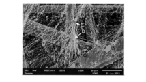
また、図2に示す修飾面3では、PTFEフィブリル5間に空隙部分が存在し、基材層2(の繊維6)は空隙部分において露出している。PTFEは、接合性の低い素材である。しかし、当該空隙部分において基材層2が露出したフィルタ濾材1では、修飾面3に対する更なる層及び/又は部材の接合性を向上できる。また、フィルタ濾材1では、修飾面3に垂直な方向から倍率500倍で修飾面3を見たときに、基材層2を構成する材料(例えば図2に示す繊維6)が露出したPTFEフィブリル5間の空隙部分が存在し、上記空隙部分において露出した上記材料の領域(上記空隙部分における上記材料の露出領域)が、修飾面上の直径5μmの仮想円を内包する形状を有していてもよい。仮想円の直径は、7μmであってもよく、10μmであってもよい。例えば図5Aは、実施例1で作製したフィルタ濾材の修飾面3に対するSEMによる観察像(倍率500倍)であるが、図5Bに示すように当該修飾面3には、修飾面3上の直径5μmの仮想の円を内包する形状を有する領域A,B及びCが存在している。また、領域A及びBは、修飾面3上の直径10μmの仮想の円を内包する形状を有している。
Furthermore, in the modified
修飾面3におけるPTFEフィブリルの修飾量は、例えば0.5g/m2未満であり、0.4g/m2以下、0.3g/m2以下、更には0.2g/m2以下であってもよい。修飾量の下限は、例えば0.1g/m2以上である。The amount of modification of the PTFE fibrils on the modified
PTFEフィブリルを構成するPTFEは、テトラフルオロエチレン単量体に由来する構成単位(TFE単位)以外の構成単位を有する変性PTFEであってもよい。ただし、変性PTFEにおけるTFE単位の含有率は、好ましくは50モル%以上であり、より好ましくは80モル%以上、更に好ましくは90モル%以上、特に好ましくは95モル%以上である。 The PTFE constituting the PTFE fibril may be a modified PTFE having a structural unit other than the structural unit (TFE unit) derived from a tetrafluoroethylene monomer. However, the content of TFE units in the modified PTFE is preferably 50 mol% or more, more preferably 80 mol% or more, still more preferably 90 mol% or more, particularly preferably 95 mol% or more.
基材層2は、厚さ方向に通気性を有する。基材層2は、例えば、繊維により構成される。基材層2を構成しうる繊維は、長繊維、短繊維及びこれらの混合繊維のいずれであってもよい。基材層2は、例えば、不織布、織布、メッシュである。通気性、強度及び柔軟性に優れることから、基材層2は不織布であることが好ましい。不織布の種類は、例えば、エアレイド不織布、メルトブローン不織布、スパンボンド不織布、サーマルボンド不織布である。2以上の異なる種類の不織布が接合された基材層2(例えば、特開2014-30825号公報に記載の通気性支持材)であってもよい。ただし、基材層2は、これらの例に限定されない。
The
基材層2を構成する材料は、例えば、ポリエチレン(PE)、ポリプロピレン(PP)等のポリオレフィン樹脂;ポリエチレンテレフタレート(PET)等のポリエステル樹脂;芳香族ポリアミドを含むポリアミド樹脂;及びこれらの複合材料である。PTFEフィブリルとの接合性に優れており、PTFEフィブリルによる基材層2の表面の修飾を比較的容易に実施できることから、当該材料は、好ましくはポリオレフィン樹脂であり、より好ましくはPEである。
Materials constituting the
基材層2を構成する複合材料の一例は、芯部と、芯部を被覆する鞘部との芯鞘構造を有する複合繊維である。複合繊維の芯部と鞘部とでは、各々の部分を構成する材料が異なっている。芯部を構成する材料の融点に比べて、鞘部を構成する材料の融点が低いことが好ましい。芯部を構成する材料は、例えば、PET等のポリエステル樹脂である。鞘部を構成する材料は、例えば、PE等のポリオレフィン樹脂である。鞘部を構成する材料がポリオレフィン樹脂である場合、PTFEフィブリルとの接合性に優れるポリオレフィン樹脂を、修飾面3である基材層2の表面に露出させることができる。
An example of the composite material constituting the
基材層2のより具体的な一例は、ポリエステル樹脂から構成される芯部と、ポリオレフィン樹脂から構成され、前記芯部を被覆する鞘部との芯鞘構造を有する複合繊維を含む不織布である。
A more specific example of the
基材層2を構成しうる繊維の平均繊維径は、例えば1~50μmであり、1~30μm、10~30μmであってもよい。
The average fiber diameter of the fibers that can constitute the
基材層2の厚さは、例えば50~1000μmであり、100~500μm、200~400μmであってもよい。
The thickness of the
基材層2の目付の上限は、例えば1000g/m2以下であり、500g/m2以下、200g/m2以下、更には100g/m2以下であってもよい。基材層2の目付の下限は、例えば10g/m2以上であり、50g/m2以上であってもよい。The upper limit of the basis weight of the
基材層2は、撥水処理及び/又は撥油処理されていてもよい。基材層に対する撥水処理及び撥油処理は、公知の手法、例えば、撥水性材料及び/又は撥油性材料を含む処理液の塗布及び乾燥、により実施できる。撥水性材料及び撥油性材料として、例えば、フッ素原子を含む各種の化合物が知られている。
The
フィルタ濾材1の修飾面3における水の接触角の上限は、例えば150°以下、130°以下、更には120°以下であってもよい。接触角の下限は、50°以上、70°以上、90°以上、更には100°以上であってもよい。本明細書において、修飾面3における水の接触角は、JIS R3257に規定する静滴法により評価した値とする。なお、JIS R3257は基板ガラス表面の接触角を評価する方法に関する規格である。しかし、当該規格で定められた試験条件により、修飾面3における水の接触角を評価可能である。
The upper limit of the contact angle of water on the modified
水中への2時間の浸漬によるフィルタ濾材1の含水率は、例えば150%以下である。フィルタ濾材1の含水率は、100%以下、更には70%以下であってもよい。フィルタ濾材1の含水率の下限は、例えば10%以上である。含水率が小さいほど、フィルタ濾材1の内部への水の浸透を抑制できる。
The water content of the
フィルタ濾材1は、修飾面3の水洗いが可能な濾材でありうる。なお、本明細書において「水洗いが可能」とは、直径47mmの円形のフィルタ濾材1とし、JIS Z8901に記載の試験用粉体である「11種 関東ローム」0.2gを修飾面3に載せて線速度20cm/秒で反対側から60秒吸引した後、約10mLの水で修飾面3を洗い流したときに、フィルタ濾材1の捕集効率CEの低下が実質的にみられないことを意味する。捕集効率CEの低下が実質的にみられないとは、捕集効率CEの低下が、例えば30%未満、好ましくは25%以下、より好ましくは20%以下であることを意味する。
The
PTFEフィブリルによる基材層2の表面の修飾により、フィルタ濾材1の捕集効率を高めることができる。被濾過気体の線速度を5.3cm/秒とし、捕集対象粒子の粒径を0.3~0.5μmの範囲としたときのフィルタ濾材1の捕集効率CEは、例えば65%以上である。捕集効率CEは、70%以上、75%以上、80%以上、85%以上、更には90%以上であってもよい。捕集効率CEは、修飾面3に垂直な方向から修飾面3を見たときに、修飾面3における基材層2の通気領域4を横断するように複数のPTFEフィブリル5が延びる場合に、特に高めることができる。
By modifying the surface of the
捕集効率CEは、次のように評価できる。同一形状を有する2つのプレートから構成される測定ホルダーを準備する。各プレートには、貫通孔(円形の断面形状及び100cm2の有効通気面積を有する)が形成されている。次に、評価対象のフィルタ濾材を双方のプレートにより挟持する。フィルタ濾材の挟持は、プレートの主面に垂直な方向から見て双方のプレートの貫通孔が一致するように、かつ、各プレートの貫通孔の開口をフィルタ濾材が覆うように実施する。また、フィルタ濾材の挟持は、各プレートとフィルタ濾材との間に隙間が生じないように行う。隙間を生じないようにするために、о-リングや両面粘着テープ等の固定部材を使用してもよい。固定部材を使用する場合、貫通孔を通過する空気の流れが固定部材によって阻害されないようにする。次に、貫通孔及び貫通孔内に位置するフィルタ濾材のみを空気が通過するように、流量計及び圧力計(マノメータ)が接続されたチャンバーにホルダーをセットする。次に、ホルダーの一方の面と他方の面との間に圧力差を発生させ、貫通孔及びフィルタ濾材に空気を流し始める。次に、貫通孔及び濾材を通過する空気の線速度が流量計の測定値にして5.3cm/秒を維持するように、圧力差を調整する。次に、粒子径0.30~0.50μm(平均粒子径0.40μm)のポリアルファオレフィン粒子を、4×108個/L以上の濃度で、濾材を通過する空気に含ませる。その後、測定ホルダーの下流に配置したパーティクルカウンタを用いて、濾材を通過した空気に含まれるポリアルファオレフィン粒子の濃度を測定し、以下の式(1)により、評価対象物の捕集効率CEを求める。
式(1):捕集効率CE=[1-(下流側の粒子濃度)/(上流側の粒子濃度)]×100(%)The collection efficiency CE can be evaluated as follows. A measurement holder consisting of two plates having the same shape is prepared. A through hole (having a circular cross-sectional shape and an effective ventilation area of 100 cm 2 ) is formed in each plate. Next, the filter medium to be evaluated is sandwiched between both plates. The filter medium is held in such a way that the through holes of both plates coincide when viewed from a direction perpendicular to the main surfaces of the plates, and so that the filter medium covers the openings of the through holes of each plate. Further, the filter media are held in such a way that no gaps are created between each plate and the filter media. In order to prevent gaps from forming, a fixing member such as an о-ring or double-sided adhesive tape may be used. When using a fixing member, ensure that the fixing member does not obstruct the flow of air passing through the through hole. Next, the holder is set in a chamber to which a flow meter and a pressure gauge (manometer) are connected so that air passes only through the through hole and the filter medium located inside the through hole. A pressure difference is then created between one side and the other side of the holder to begin flowing air through the through holes and the filter media. Next, the pressure difference is adjusted so that the linear velocity of the air passing through the through holes and the filter medium is maintained at 5.3 cm/sec as measured by the flow meter. Next, polyalphaolefin particles having a particle size of 0.30 to 0.50 μm (average particle size 0.40 μm) are included in the air passing through the filter medium at a concentration of 4×10 8 particles/L or more. After that, the concentration of polyalphaolefin particles contained in the air that has passed through the filter medium is measured using a particle counter placed downstream of the measurement holder, and the collection efficiency CE of the evaluation target is calculated using the following formula (1). demand.
Formula (1): Collection efficiency CE = [1-(downstream particle concentration)/(upstream particle concentration)] x 100 (%)
PTFEフィブリルによる基材層2の表面の修飾では、フィルタ濾材1の圧力損失の増大を抑制しながら、捕集効率CEを高めることができる。
By modifying the surface of the
5.3cm/秒の線速度で空気を透過させたときのフィルタ濾材1の圧力損失PLは、例えば40Pa未満である。圧力損失PLは、35Pa以下、30Pa以下、25Pa以下、更には20Pa以下であってもよい。
The pressure loss PL of the
圧力損失PLは、次のように評価できる。同一形状を有する2つのプレートから構成される測定ホルダーを準備する。各プレートには、貫通孔(円形の断面形状及び100cm2の有効通気面積を有する)が形成されている。次に、評価対象のフィルタ濾材を双方のプレートにより挟持する。フィルタ濾材の挟持は、プレートの主面に垂直な方向から見て双方のプレートの貫通孔が一致するように、かつ、各プレートの貫通孔の開口をフィルタ濾材が覆うように実施する。また、フィルタ濾材の挟持は、各プレートとフィルタ濾材との間に隙間が生じないように行う。隙間を生じないようにするために、о-リングや両面粘着テープ等の固定部材を使用してもよい。固定部材を使用する場合、貫通孔を通過する空気の流れが固定部材によって阻害されないようにする。次に、貫通孔及び貫通孔内に位置するフィルタ濾材のみを空気が通過するように、流量計及び圧力計(マノメータ)が接続されたチャンバーにホルダーをセットする。次に、ホルダーの一方の面と他方の面との間に圧力差を発生させ、貫通孔及びフィルタ濾材に空気を流し始める。貫通孔及びフィルタ濾材を通過する空気の線速度が流量計の測定値にして5.3cm/秒となったときの上記圧力差(静圧差)を、圧力計により測定する。1つの濾材に対して上記圧力差を8回測定し、その平均値を、評価対象であるフィルタ濾材の圧力損失PLとする。Pressure loss PL can be evaluated as follows. A measurement holder consisting of two plates having the same shape is prepared. A through hole (having a circular cross-sectional shape and an effective ventilation area of 100 cm 2 ) is formed in each plate. Next, the filter medium to be evaluated is sandwiched between both plates. The filter medium is held in such a way that the through holes of both plates coincide when viewed from a direction perpendicular to the main surfaces of the plates, and so that the filter medium covers the openings of the through holes of each plate. Further, the filter media are held in such a way that no gaps are created between each plate and the filter media. In order to prevent gaps from forming, a fixing member such as an о-ring or double-sided adhesive tape may be used. When using a fixing member, ensure that the fixing member does not obstruct the flow of air passing through the through hole. Next, the holder is set in a chamber to which a flow meter and a pressure gauge (manometer) are connected so that air passes only through the through hole and the filter material located inside the through hole. A pressure difference is then created between one side and the other side of the holder to begin flowing air through the through holes and the filter media. The pressure difference (static pressure difference) is measured using a pressure gauge when the linear velocity of the air passing through the through holes and the filter medium becomes 5.3 cm/sec as measured by the flowmeter. The pressure difference is measured eight times for one filter medium, and the average value is taken as the pressure loss PL of the filter medium to be evaluated.
フィルタ濾材1における捕集効率と圧力損失とのバランスを示すPF(Performance Factor)値は、例えば30以上であり、32以上、33以上、更には34以上であってもよい。フィルタ濾材1のPF値は、フィルタ濾材1の圧力損失PL及び捕集効率CEから、以下の式(2)により求められる。
式(2):PF値={-lоg[(100-CE)/100]/(PL/9.8)}×100The PF (Performance Factor) value indicating the balance between collection efficiency and pressure loss in the
Formula (2): PF value = {-log[(100-CE)/100]/(PL/9.8)}×100
フィルタ濾材1の各特性は、例えば、基材層2の構成及び/又はPTFEフィブリルによる修飾面3の修飾の状態により制御できる。修飾面3の修飾の状態は、例えば、後述する「PTFE修飾体」の構成により制御できる。
Each characteristic of the
フィルタ濾材1は、通気性を有する基材層を2以上備えていてもよい。ただし、この場合、2以上の基材層の少なくとも1層が、修飾面3を有する基材層2である。フィルタ濾材1を構成する2以上の基材層の全てが修飾面3を有していてもよい。フィルタ濾材1は、例えば、2つの基材層から構成されると共に、当該2つの基材層の間に修飾面3を有していてもよい。2つの基材層の間に修飾面3を有するフィルタ濾材1では、修飾面3におけるPTFEフィブリル間の空隙部分において、一方の基材層と他方の基材層とが直接接合していてもよい。また、2つの基材層の間に修飾面3を有するフィルタ濾材1では、フィルタ濾材1の使用時に気流の上流側に位置する一方の基材層を、気流に含まれる比較的大きなサイズの粒子を捕集するプレフィルタとして使用することもできる。
The
修飾面3を有さない基材層は、修飾面3を有さない以外は、基材層2の説明において上述した構成を有することができる。
The base material layer that does not have the modified
フィルタ濾材1の目付は、例えば10~1000g/m2であり、30~500g/m2、50~100g/m2であってもよい。フィルタ濾材1の目付は、フィルタ濾材1の重量を主面の面積で除して求めることができる。The basis weight of the
フィルタ濾材1の厚さは、例えば50~1000μmであり、100~500μm、200~400μmであってもよい。
The thickness of the
修飾面3を有する基材層2を備える限り、フィルタ濾材1は、任意の層及び/又は部材を備えていてもよい。
As long as the
フィルタ濾材1は、例えば、被修飾体である原基材層と、PTFEにより構成される修飾体(以下、「PTFE修飾体」と記載する)とを熱ラミネートして形成できる。ただし、フィルタ濾材1を形成する方法は、原基材層とPTFE修飾体とを熱ラミネートする方法に限定されない。
The
熱ラミネートによりフィルタ濾材1を形成する場合、原基材層におけるPTFE修飾体の接合面が修飾面3となる。なお、一般的な積層ラミネート体とは異なり、PTFE修飾体の接合により形成された基材層2の修飾面3は露出面であってもよい。原基材層は、修飾面3を有さない以外は、基材層2の説明において上述した構成を有することができる。
When the
PTFE修飾体は、典型的には、微細な繊維状構造体である無数のPTFEフィブリルにより構成される。PTFE修飾体は、複数のフィブリルに接続されたPTFEのノードを有していてもよい。この場合、形成されたフィルタ濾材1の修飾面3にノードが存在することがある。ノードは、典型的には、修飾面3の拡大像において、2μm2以上の面積を有するPTFEの結節部として観察される。面積は、3μm2以上、5μm2以上、7μm2以上、更には10μm2以上であってもよい。面積の上限は、例えば450μm2以下である。ノードの短軸方向の長さに対する長軸方向の長さの比は、例えば10以下であり、7以下、5以下、3以下、更には2以下であってもよい。拡大像は、例えば、SEM及び光学顕微鏡等の拡大観察手法により、得ることができる。A PTFE modified product is typically composed of numerous PTFE fibrils, which are fine fibrous structures. The PTFE modification may have nodes of PTFE connected to multiple fibrils. In this case, nodes may exist on the modified
PTFE修飾体は、例えば、未焼成のPTFE粉末(ファインパウダー)と液状潤滑剤との混和物を押出及び/又は圧延等の手法によりフィルムに成形し、得られた未焼成のフィルムから液状潤滑剤を除去した後、延伸することにより形成できる。液状潤滑剤は、例えば、ナフサ、ホワイトオイル、ドデカン、流動パラフィン等の炭化水素油である。ただし、液状潤滑剤は、PTFE粉末の表面を濡らすことができると共に、乾燥等の手法によって後に除去できるものであれば限定されない。延伸は、例えば、フィルムのMD方向(長手方向)に対する延伸倍率5~100倍、延伸温度100~380℃の縦延伸と、当該フィルムのTD方向(幅方向)に対する延伸倍率10~300倍、延伸温度100~380℃の横延伸とを組み合わせた二軸延伸である。縦延伸の延伸倍率の下限は、5倍超であってもよく、20倍以上であってもよい。横延伸の延伸倍率の下限は、10倍超であってもよく、30倍以上であってもよい。縦延伸及び横延伸は、いずれの延伸を先に実施してもよい。また、縦延伸と横延伸との間で、延伸条件(延伸倍率及び延伸温度)が上記とは逆であってもよい。縦延伸の延伸倍率と横延伸の延伸倍率との積である総延伸倍率は、例えば10000倍以上であり、12000倍以上、13000倍以上、14000倍以上、更には15000倍以上であってもよい。未焼成フィルムの形成後、任意のタイミングにおいて、PTFEの融点以上の温度にフィルムを加熱する焼成を実施してもよい。ただし、PTFEの融点以上の延伸温度での延伸を実施する場合は、延伸により形成されたPTFEフィブリルが互いに融着することを防ぐために、焼成の実施を省略することが好ましい。 The PTFE modified product can be produced by, for example, forming a mixture of unfired PTFE powder (fine powder) and a liquid lubricant into a film by extrusion and/or rolling, and then forming the liquid lubricant from the resulting unfired film. It can be formed by removing and then stretching. Liquid lubricants are, for example, hydrocarbon oils such as naphtha, white oil, dodecane, and liquid paraffin. However, the liquid lubricant is not limited as long as it can wet the surface of the PTFE powder and can be removed later by a method such as drying. Stretching includes, for example, longitudinal stretching at a stretching ratio of 5 to 100 times in the MD direction (longitudinal direction) of the film and a stretching temperature of 100 to 380°C, and stretching at a stretching ratio of 10 to 300 times in the TD direction (width direction) of the film. This is biaxial stretching combined with transverse stretching at a temperature of 100 to 380°C. The lower limit of the stretching ratio for longitudinal stretching may be more than 5 times, or may be 20 times or more. The lower limit of the stretching ratio for transverse stretching may be more than 10 times, or may be 30 times or more. Either longitudinal stretching or transverse stretching may be performed first. Furthermore, the stretching conditions (stretching ratio and stretching temperature) may be reversed between the longitudinal stretching and the lateral stretching. The total stretching ratio, which is the product of the stretching ratio of longitudinal stretching and the stretching ratio of horizontal stretching, is, for example, 10,000 times or more, and may be 12,000 times or more, 13,000 times or more, 14,000 times or more, or even 15,000 times or more. . After the unfired film is formed, firing may be performed at any timing to heat the film to a temperature equal to or higher than the melting point of PTFE. However, when stretching is performed at a stretching temperature equal to or higher than the melting point of PTFE, it is preferable to omit the firing in order to prevent the PTFE fibrils formed by the stretching from fusing together.
PTFE修飾体の厚さは、例えば3.0μm未満であり、2.5μm以下、2.0μm以下、更には1.8μm以下であってもよい。PTFE修飾体の厚さの下限は、例えば0.1μm以上である。 The thickness of the PTFE modified body is, for example, less than 3.0 μm, and may be 2.5 μm or less, 2.0 μm or less, or even 1.8 μm or less. The lower limit of the thickness of the modified PTFE body is, for example, 0.1 μm or more.
PTFE修飾体の目付は、例えば0.5g/m2未満であり、0.4g/m2以下、0.3g/m2以下、更には0.2g/m2以下であってもよい。PTFE修飾体の目付の下限は、例えば0.1g/m2以上である。PTFE修飾体の目付によって、修飾面3におけるPTFEフィブリルの修飾量を制御できる。The basis weight of the PTFE modified product is, for example, less than 0.5 g/m 2 , and may be 0.4 g/m 2 or less, 0.3 g/m 2 or less, or even 0.2 g/m 2 or less. The lower limit of the basis weight of the modified PTFE is, for example, 0.1 g/m 2 or more. The amount of modification of the PTFE fibrils on the modified
フィルタ濾材1は、例えば、空気等の気体を透過させて当該気体に含まれる塵芥等の異物を除去するために使用できる。フィルタ濾材1は、典型的には、空気を透過させるエアフィルタ濾材である。
The
基材層2の修飾面3が露出しているフィルタ濾材1は、修飾面3が気流の最上流側に位置するように使用してもよい。
The
フィルタ濾材1は、例えば、空気清浄機、空調機及び掃除機等の各種の製品に使用できる。空調機及び空気清浄機には、室内での使用を主に想定した小型の製品以外にも、建物の空調システム等の大型の製品、及び自動車や鉄道車両等の輸送機器が備える製品が含まれる。ただし、フィルタ濾材1の用途は、これらの例に限定されない。
The
フィルタ濾材1は、以下に示すフィルタユニットとして使用してもよい。
The
[フィルタユニット]
図3に、本開示のフィルタユニットの一例を示す。図3に示すフィルタユニット11は、フィルタ濾材1がプリーツ加工されてなるフィルタプリーツパック12と、プリーツパック12を支持する枠体13と、を備える。枠体13は、フィルタプリーツパック12の周端部を全周にわたって支持している。ただし、本開示のフィルタユニットの構成は、図3に示す例に限定されない。[Filter unit]
FIG. 3 shows an example of a filter unit of the present disclosure. The
図4に示すように、フィルタプリーツパック12は、シート状のフィルタ濾材1がプリーツ形状に折り畳まれた構造を有する。また、フィルタプリーツパック12はビード14を有している。ビード14は、樹脂から構成される紐状体であり、フィルタ濾材1のプリーツ形状を維持するスペーサーの一種である。ビード14は、フィルタ濾材1のプリーツ線15(折り線)と交差する方向に沿って進む連続線又は断続線を描くように、折り畳まれたフィルタ濾材1の表面に配置されている。
As shown in FIG. 4, the
フィルタプリーツパック12においてビード14は、フィルタ濾材1の一方の表面に配置されていても、双方の表面に配置されていてもよい。基材層2の修飾面3が露出しているフィルタ濾材1では、修飾面3にビード14が配置されていてもよい。ビード14は、例えば、フィルタ濾材1の表面に溶融樹脂を紐状に塗布して形成できる。ビード14を構成する樹脂は限定されず、例えば、ポリアミド、ポリオレフィン、エチレン-酢酸ビニル共重合体である。
In the
フィルタ濾材1のプリーツ加工には公知の方法を適用できる。フィルタ濾材1のプリーツ加工は、例えば、レシプロ式又はロータリー式のプリーツ加工機を用いて実施できる。
A known method can be applied to pleat the
枠体13は、例えば、金属、樹脂又はこれらの複合材料から構成される。枠体13が樹脂から構成される場合、枠体13の成形と同時にフィルタプリーツパック12を枠体13に固定することも可能である。枠体13の構成は、従来のフィルタユニットが備える枠体の構成と同じであってもよい。
The
フィルタユニット11は、上述した部材以外の任意の部材を備えていてもよい。
The
フィルタユニット11は、例えば、空気等の気体を透過させて当該気体に含まれる塵芥等の異物を除去するために使用できる。フィルタユニット11は、典型的には、空気を透過させるエアフィルタユニットである。
The
フィルタユニット11は、例えば、空気清浄機、空調機及び掃除機等の各種の製品に使用できる。空調機及び空気清浄機には、室内での使用を主に想定した小型の製品以外にも、建物の空調システム等の大型の製品、及び自動車や鉄道車両等の輸送機器が備える製品が含まれる。ただし、フィルタユニット11の用途は、これらの例に限定されない。
The
以下、実施例により、本発明をさらに具体的に説明する。本発明は、以下に示す実施例に限定されない。 EXAMPLES Hereinafter, the present invention will be explained in more detail with reference to Examples. The invention is not limited to the examples shown below.
本実施例において作製したフィルタ濾材の評価方法を以下に示す。 A method for evaluating the filter material produced in this example is shown below.
[厚さ]
基材層及びフィルタ濾材の厚さは、デジタルダイヤルゲージにより評価した。また、PTFE修飾体の厚さは、以下のように評価した。最初に、評価対象物であるPTFE修飾体をエポキシ樹脂に包埋した後、PTFE修飾体を含む断面を露出させて研磨及び整面し、更にイオンポリッシング加工した。次に、電解放出型SEM(FE-SEM;日本電子製JSM-7500F、加速電圧5kV、反射電子像)を用いて得た当該断面の拡大観察像(倍率500倍程度)を画像解析することで、PTFE修飾体の厚さを求めた。ただし、画像解析の際には、場所を変えながら少なくとも10の測定ポイントにおける厚さを評価し、その平均値をPTFE修飾体の厚さとした。なお、FE-SEMを用いた上記方法は、フィルタ濾材に含まれる基材層及びPTFE修飾体の厚さの評価にも適用できる。[thickness]
The thickness of the base layer and the filter medium was evaluated using a digital dial gauge. Moreover, the thickness of the PTFE modified body was evaluated as follows. First, the PTFE modified body to be evaluated was embedded in an epoxy resin, and then the cross section containing the PTFE modified body was exposed, polished and smoothed, and further subjected to ion polishing. Next, an enlarged observation image (about 500x magnification) of the cross section obtained using a field emission SEM (FE-SEM; JEOL JSM-7500F, accelerating
[目付]
PTFE修飾体の目付は、PTFE修飾体の重量を主面の面積で除して求めた。[Weight]
The basis weight of the modified PTFE product was determined by dividing the weight of the modified PTFE product by the area of the main surface.
[圧力損失PL及び捕集効率CE]
フィルタ濾材の圧力損失PL及び捕集効率CEは、上述の方法により評価した。[Pressure loss PL and collection efficiency CE]
The pressure loss PL and collection efficiency CE of the filter medium were evaluated by the above-mentioned method.
[接触角]
フィルタ濾材の修飾面(実施例1)又は上流側(捕集効率を評価する際の上流側)の主面(比較例1,2)における水との接触角は、JIS R3257(基板ガラス表面のぬれ性試験方法、静滴法)に従い、接触角測定装置(Contact Angle System OCA 30、DataPhysics Instruments GmbH製)を用いて測定した。[Contact angle]
The contact angle with water on the modified surface (Example 1) or the main surface (Comparative Examples 1 and 2) on the upstream side (upstream side when evaluating the collection efficiency) of the filter medium is determined according to JIS R3257 (on the substrate glass surface). It was measured using a contact angle measuring device (Contact Angle System OCA 30, manufactured by DataPhysics Instruments GmbH) according to the wettability test method (sessile drop method).
[含水率]
フィルタ濾材の含水率は、以下のように評価した。最初に、評価対象のフィルタ濾材を150mm×125mmの長方形に切り出して試験片を得た。次に、25℃及び65%RHの雰囲気に少なくとも12時間、試験片を放置した後、試験片の重量(乾燥時重量W1)を測定した。次に、試験片の全体を水中に浸漬して2時間放置した。次に、水中から試験片を取り出して表面に付着している水滴をふき取った後、その重量(湿潤時重量W2)を測定した。測定した重量W1及びW2から、以下の式により、フィルタ濾材の含水率を求めた。
式:含水率=(W2-W1)/W1×100(%)[Moisture content]
The water content of the filter medium was evaluated as follows. First, the filter medium to be evaluated was cut into a rectangle of 150 mm x 125 mm to obtain a test piece. Next, after leaving the test piece in an atmosphere of 25° C. and 65% RH for at least 12 hours, the weight of the test piece (dry weight W1) was measured. Next, the entire test piece was immersed in water and left for 2 hours. Next, the test piece was taken out of the water, water droplets adhering to the surface were wiped off, and its weight (wet weight W2) was measured. From the measured weights W1 and W2, the water content of the filter medium was determined using the following formula.
Formula: Moisture content = (W2-W1)/W1 x 100 (%)
[水洗い性]
フィルタ濾材の水洗い性は、以下のように評価した。最初に、評価対象のフィルタ濾材を直径47mmの円形に切り出して試験片を得た。次に、試験片の修飾面(実施例1)又は上流側の主面(比較例1,2)に、JIS Z8901に記載の試験用粉体である「11種 関東ローム」0.2gを満遍なく載せ、試験片の反対側から線速度20cm/秒で60秒吸引した。次に、粉体の戴置面を垂直に保持し、約10mLの水を洗瓶を用いて戴置面の全体に流しかけることで、粉体を洗い流した。次に、フィルタ濾材の捕集効率CEを評価し、粉体を戴置する前の捕集効率CEとの差が30%未満である場合を「水洗い性/良(○)」、30%以上である場合を「水洗い性/不可(×)」とした。[Washability]
The water washability of the filter medium was evaluated as follows. First, a test piece was obtained by cutting the filter medium to be evaluated into a circular shape with a diameter of 47 mm. Next, 0.2 g of "
[フィルタ濾材の作製]
(実施例1)
PTFEファインパウダー(ダイキン工業製、F-104)100重量部と、液状潤滑剤であるドデカン19重量部とを均一に混合し、得られた混合物を予備成形した。次に、予備成形物をシート状にペースト押出成形し、得られた成形体をロール圧延して、厚さ200μmの帯状のシートを得た。次に、得られたシートから液状潤滑剤を乾燥除去した後、シートのMD方向に延伸温度280℃、延伸倍率85倍で延伸し、続いてTD方向に延伸温度150℃、延伸倍率200倍でテンター法により延伸して、PTFEのフィブリルから構成される修飾体Aを得た。得られた修飾体Aの厚さは1.5μm、目付は0.2g/m2であった。[Preparation of filter media]
(Example 1)
100 parts by weight of PTFE fine powder (manufactured by Daikin Industries, Ltd., F-104) and 19 parts by weight of dodecane as a liquid lubricant were uniformly mixed, and the resulting mixture was preformed. Next, the preform was paste-extruded into a sheet shape, and the obtained molded product was roll-rolled to obtain a belt-shaped sheet with a thickness of 200 μm. Next, after drying and removing the liquid lubricant from the obtained sheet, the sheet was stretched in the MD direction at a stretching temperature of 280°C and a stretching ratio of 85 times, and then in the TD direction at a stretching temperature of 150°C and a stretching ratio of 200 times. A modified product A composed of PTFE fibrils was obtained by stretching by a tenter method. The thickness of the obtained modified product A was 1.5 μm, and the basis weight was 0.2 g/m 2 .
次に、基材層であるエアレイド不織布/PET不織布接合体(厚さ320μm、目付100g/m2、PETの芯部及びPEの鞘部の芯鞘構造を有する複合繊維からエアレイド不織布が構成、特開2014-30825号公報の段落0071~0073に記載の方法により作製)と、修飾体Aとを積層し、積層体を熱ラミネートして、修飾体Aによる修飾面を有する基材層からなるフィルタ濾材Aを得た。熱ラミネートは、エアレイド不織布と修飾体Aとが接するように実施した。得られたフィルタ濾材Aの圧力損失PLは20Pa、捕集効率CEは80%であった。また、修飾体Aによる修飾量は0.2g/m2であった。フィルタ濾材Aの修飾面に対するSEMによる観察像(倍率500倍)を図5Aに示す。Next, the airlaid nonwoven fabric/PET nonwoven fabric bonded body (thickness 320 μm, basis weight 100 g/m 2 , airlaid nonwoven fabric made of composite fibers having a core-sheath structure of a PET core and a PE sheath), which is a base material layer, 2014-30825 Publication No. 2014-30825) and modified body A, the laminate is thermally laminated, and the filter consists of a base material layer having a surface modified by modified body A. Filter medium A was obtained. Thermal lamination was carried out so that the air-laid nonwoven fabric and modified body A were in contact with each other. The pressure loss PL of the obtained filter medium A was 20 Pa, and the collection efficiency CE was 80%. Further, the amount of modification by Modifier A was 0.2 g/m 2 . An SEM observation image (magnification: 500 times) of the modified surface of filter medium A is shown in FIG. 5A.
図5Aに示すように、フィルタ濾材Aにおける修飾面には、PTFEフィブリル間の空隙部分であって、基材層を構成する繊維が露出した空隙部分が多数存在していた。また、上記空隙部分において露出した上記繊維の領域の中に、修飾面上の直径5μmの仮想の円を内包する形状を有する領域A,B及びCが存在していた(図5Bを参照)。なかでも領域A及びBは大きく、修飾面上の直径10μmの仮想の円を内包する形状を有していた。更に、フィルタ濾材Aにおける修飾面では、基材層の通気領域を横断するように複数のPTFEフィブリルが延びていた。また、修飾面には、ノードD及びEを含む複数のPTFEのノードが観察された。なお、図5Aには、PTFEフィブリル間の空隙部分に露出した基材層の繊維が、熱ラミネートの際の圧力によって平板状に変形している状態が示されている。 As shown in FIG. 5A, on the modified surface of filter medium A, there were many voids between the PTFE fibrils, in which the fibers constituting the base layer were exposed. Further, in the region of the fibers exposed in the void portion, there were regions A, B, and C having a shape that included a virtual circle with a diameter of 5 μm on the modified surface (see FIG. 5B). Among them, regions A and B were large and had a shape that included an imaginary circle with a diameter of 10 μm on the modified surface. Furthermore, on the modified surface of filter medium A, a plurality of PTFE fibrils extended across the ventilation area of the base layer. Moreover, a plurality of PTFE nodes including nodes D and E were observed on the modified surface. Note that FIG. 5A shows a state in which the fibers of the base layer exposed in the gaps between the PTFE fibrils are deformed into a flat plate shape by the pressure during thermal lamination.
フィルタ濾材Aの評価結果を以下の表1に示す。 The evaluation results for filter medium A are shown in Table 1 below.
(比較例1)
実施例1で準備した不織布接合体を比較例1のフィルタ濾材Bとした。フィルタ濾材Bは、エアレイド不織布を上流側に配置して用いた。フィルタ濾材Bの評価結果を以下の表1に、上流側の主面に対するSEMによる観察像を図6に示す。(Comparative example 1)
The nonwoven fabric bonded body prepared in Example 1 was used as filter medium B of Comparative Example 1. Filter medium B was used by arranging air-laid nonwoven fabric on the upstream side. The evaluation results of filter medium B are shown in Table 1 below, and an SEM observation image of the main surface on the upstream side is shown in FIG.
(比較例2)
実施例1で準備した不織布接合体を比較例2のフィルタ濾材Cとした。フィルタ濾材Cは、PET不織布を上流側に配置して用いた。フィルタ濾材Cの評価結果を以下の表1に、上流側の主面に対するSEMによる観察像を図7に示す。図7に示すように、PET不織布を構成する繊維の表面には撥水剤が付着していた。(Comparative example 2)
The nonwoven fabric bonded body prepared in Example 1 was used as filter medium C of Comparative Example 2. The filter medium C was a PET nonwoven fabric placed on the upstream side. The evaluation results of the filter medium C are shown in Table 1 below, and the SEM observation image of the main surface on the upstream side is shown in FIG. As shown in FIG. 7, the water repellent agent was attached to the surface of the fibers constituting the PET nonwoven fabric.
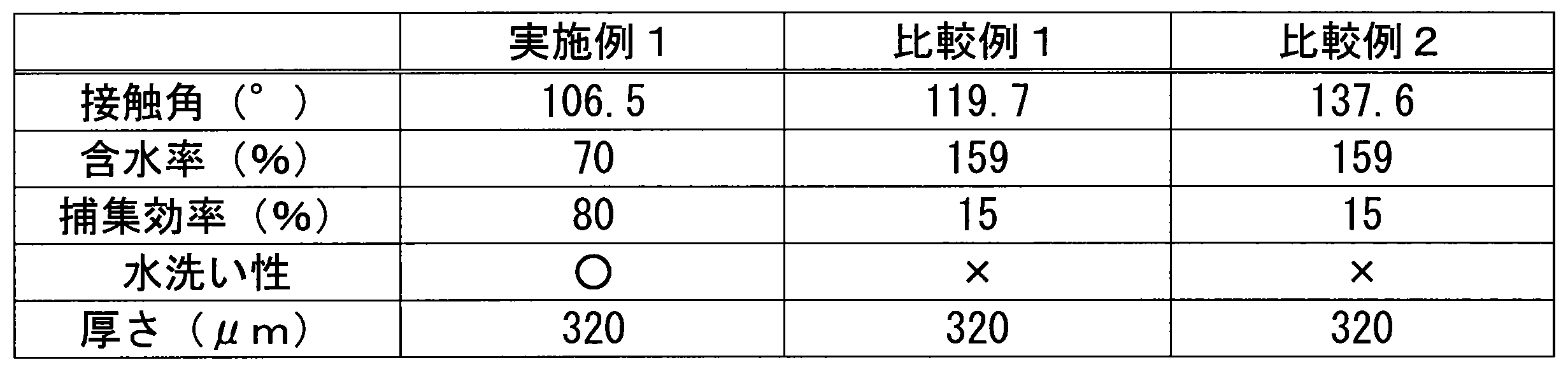
表1に示すように、実施例のフィルタ濾材では、比較例のフィルタ濾材に比べて含水率が大きく低下した。また、捕集効率の著しい上昇が確認された。 As shown in Table 1, the water content of the filter media of Examples was significantly lower than that of the filter media of Comparative Examples. In addition, a significant increase in collection efficiency was confirmed.
本発明のフィルタ濾材は、従来のフィルタ濾材が使用されている用途に使用できる。 The filter media of the present invention can be used in applications where conventional filter media are used.
Claims (8)
前記基材層は、前記修飾体に含まれるポリテトラフルオロエチレンのフィブリルによる修飾面を有し、
前記修飾面において前記基材層に接合した前記修飾体の目付が0.3g/m2以下であり、
前記修飾面に垂直な方向から前記修飾面を見たときに、前記ポリテトラフルオロエチレンの前記フィブリルの間に空隙部分が存在し、前記基材層は前記空隙部分において露出しているフィルタ濾材。 comprising a base layer having air permeability and a modified polytetrafluoroethylene bonded to the base layer,
The base layer has a modified surface with polytetrafluoroethylene fibrils included in the modified product ,
The basis weight of the modified body bonded to the base material layer on the modified surface is 0.3 g/m 2 or less,
When the modified surface is viewed from a direction perpendicular to the modified surface, a void portion exists between the fibrils of the polytetrafluoroethylene, and the base layer is exposed in the void portion.
前記基材層を構成する材料が露出した前記フィブリル間の空隙部分が存在し、
前記材料における前記空隙部分において露出した領域が、前記修飾面上の直径5μmの仮想の円を内包する形状を有する、請求項1又は2に記載のフィルタ濾材。 When the modified surface is viewed at a magnification of 500 times from a direction perpendicular to the modified surface,
There is a gap between the fibrils in which the material constituting the base layer is exposed,
The filter medium according to claim 1 or 2, wherein the region exposed in the void portion of the material has a shape that includes an imaginary circle with a diameter of 5 μm on the modified surface.
Applications Claiming Priority (3)
| Application Number | Priority Date | Filing Date | Title |
|---|---|---|---|
| JP2018106513 | 2018-06-01 | ||
| JP2018106513 | 2018-06-01 | ||
| PCT/JP2019/021892 WO2019230984A1 (en) | 2018-06-01 | 2019-05-31 | Filter medium and filter unit provided with same |
Publications (2)
| Publication Number | Publication Date |
|---|---|
| JPWO2019230984A1 JPWO2019230984A1 (en) | 2021-07-01 |
| JP7356972B2 true JP7356972B2 (en) | 2023-10-05 |
Family
ID=68698223
Family Applications (1)
| Application Number | Title | Priority Date | Filing Date |
|---|---|---|---|
| JP2020522648A Active JP7356972B2 (en) | 2018-06-01 | 2019-05-31 | Filter medium and filter unit equipped with the same |
Country Status (7)
| Country | Link |
|---|---|
| US (1) | US20210162354A1 (en) |
| EP (1) | EP3812026A4 (en) |
| JP (1) | JP7356972B2 (en) |
| KR (1) | KR20210014137A (en) |
| CN (1) | CN112218696B (en) |
| TW (1) | TW202012033A (en) |
| WO (1) | WO2019230984A1 (en) |
Citations (4)
| Publication number | Priority date | Publication date | Assignee | Title |
|---|---|---|---|---|
| JP2000140587A (en) | 1998-11-16 | 2000-05-23 | Tonen Tapirusu Kk | Filter unit and dust mask using the same |
| JP2009101254A (en) | 2007-10-19 | 2009-05-14 | Japan Gore Tex Inc | Air filter and air filter for vacuum cleaner using this air filter |
| JP2013032514A (en) | 2011-07-05 | 2013-02-14 | Nitto Denko Corp | Polytetrafluoroethylene porous membrane and air filter medium |
| JP2013173078A (en) | 2012-02-23 | 2013-09-05 | Nitto Denko Corp | Blended nonwoven fabric, filter medium, and filter unit |
Family Cites Families (16)
| Publication number | Priority date | Publication date | Assignee | Title |
|---|---|---|---|---|
| JP3273735B2 (en) * | 1996-05-17 | 2002-04-15 | 日東電工株式会社 | Polytetrafluoroethylene porous membrane and method for producing the same, sheet-like polytetrafluoroethylene molded article, and filter medium for air filter |
| JP2000176262A (en) * | 1998-12-11 | 2000-06-27 | Daikin Ind Ltd | Porous materials, air filter media, air filter units and support materials for air filter media |
| JP3584855B2 (en) * | 1999-10-07 | 2004-11-04 | ダイキン工業株式会社 | Air filter media |
| JP3500406B2 (en) * | 2000-03-30 | 2004-02-23 | 日本フエルト株式会社 | Felt filter material |
| JP4329559B2 (en) | 2003-05-02 | 2009-09-09 | ダイキン工業株式会社 | Surface treatment agent comprising fluorine-containing polymer |
| JP2007083163A (en) * | 2005-09-22 | 2007-04-05 | Yoshikazu Saito | Molded filter for incineration system and method for manufacturing the same |
| JP4963185B2 (en) * | 2006-03-28 | 2012-06-27 | 日東電工株式会社 | Polytetrafluoroethylene porous membrane production method, filter medium and filter unit |
| EP2221096B1 (en) | 2007-11-14 | 2017-03-22 | Nitto Denko Corporation | Filter filtration material, method for producing the same and filter unit |
| JP5133039B2 (en) * | 2007-12-07 | 2013-01-30 | 日東電工株式会社 | Polytetrafluoroethylene porous membrane, method for producing the same, and waterproof air-permeable filter |
| CN101507889A (en) * | 2009-02-17 | 2009-08-19 | 江苏阜升环保设备制造有限责任公司 | Multifunctional high-temperature composite filter material and preparation method thereof |
| JP5784458B2 (en) * | 2011-10-31 | 2015-09-24 | 日東電工株式会社 | Air filter media |
| CN203564873U (en) * | 2013-10-25 | 2014-04-30 | 河南省安克林滤业有限公司 | Flame-retardant water-washable film-coated filter material |
| CN103861482A (en) * | 2014-03-25 | 2014-06-18 | 湖州森诺氟材料科技有限公司 | Polytetrafluoroethylene air-cleaning filtering membrane |
| CN103961937A (en) * | 2014-04-30 | 2014-08-06 | 桐乡市健民过滤材料有限公司 | Membrane filter material with high temperature resistance and high flame retardancy and preparation method thereof |
| CN105080364A (en) * | 2014-05-20 | 2015-11-25 | 江苏东邦科技有限公司 | Teflon composite membrane co-stretching preparation method |
| US10220353B2 (en) * | 2014-08-28 | 2019-03-05 | Bha Altair, Llc | Filter water management using hydrophilic material |
-
2019
- 2019-05-31 JP JP2020522648A patent/JP7356972B2/en active Active
- 2019-05-31 US US17/059,309 patent/US20210162354A1/en not_active Abandoned
- 2019-05-31 EP EP19810027.3A patent/EP3812026A4/en not_active Withdrawn
- 2019-05-31 WO PCT/JP2019/021892 patent/WO2019230984A1/en not_active Ceased
- 2019-05-31 CN CN201980036922.9A patent/CN112218696B/en active Active
- 2019-05-31 KR KR1020207037118A patent/KR20210014137A/en not_active Ceased
- 2019-06-03 TW TW108119187A patent/TW202012033A/en unknown
Patent Citations (4)
| Publication number | Priority date | Publication date | Assignee | Title |
|---|---|---|---|---|
| JP2000140587A (en) | 1998-11-16 | 2000-05-23 | Tonen Tapirusu Kk | Filter unit and dust mask using the same |
| JP2009101254A (en) | 2007-10-19 | 2009-05-14 | Japan Gore Tex Inc | Air filter and air filter for vacuum cleaner using this air filter |
| JP2013032514A (en) | 2011-07-05 | 2013-02-14 | Nitto Denko Corp | Polytetrafluoroethylene porous membrane and air filter medium |
| JP2013173078A (en) | 2012-02-23 | 2013-09-05 | Nitto Denko Corp | Blended nonwoven fabric, filter medium, and filter unit |
Also Published As
| Publication number | Publication date |
|---|---|
| EP3812026A4 (en) | 2022-03-16 |
| TW202012033A (en) | 2020-04-01 |
| EP3812026A1 (en) | 2021-04-28 |
| CN112218696A (en) | 2021-01-12 |
| WO2019230984A1 (en) | 2019-12-05 |
| KR20210014137A (en) | 2021-02-08 |
| US20210162354A1 (en) | 2021-06-03 |
| JPWO2019230984A1 (en) | 2021-07-01 |
| CN112218696B (en) | 2022-12-30 |
Similar Documents
| Publication | Publication Date | Title |
|---|---|---|
| CN110430932B (en) | Filter media comprising a wave filter layer with a gradient | |
| US20180236385A1 (en) | Electret-containing filter media | |
| CN102015080A (en) | Polyethylene membrane and method of its production | |
| JP6861493B2 (en) | Air filter filter media, air filter pack and air filter unit | |
| TW201813704A (en) | Air filter media, air filter unit and air filter unit | |
| JP2014124578A (en) | Filtration material for filter and production method of the same | |
| JP7356971B2 (en) | Filter medium and filter unit equipped with the same | |
| WO2022092161A1 (en) | Filter pleat pack, and air filter unit | |
| JP7356972B2 (en) | Filter medium and filter unit equipped with the same | |
| JP2007160275A (en) | Filter unit and manufacturing method thereof | |
| WO2022065516A1 (en) | Air filter filtering medium, filter pritz pack, and air filter unit | |
| WO2022065517A1 (en) | Air filter filtering medium, filter pleat pack, and air filter unit | |
| JP7527781B2 (en) | Filter pleat packs and air filter units | |
| JP7527780B2 (en) | Filter pleat packs and air filter units | |
| JP7405837B2 (en) | Filter media and filter unit | |
| WO2024111445A1 (en) | Filter medium for air filters, filter pleat pack and air filter unit | |
| WO2022065515A1 (en) | Air filter filtration member, filter pleat pack, and air filter unit |
Legal Events
| Date | Code | Title | Description |
|---|---|---|---|
| A621 | Written request for application examination |
Free format text: JAPANESE INTERMEDIATE CODE: A621 Effective date: 20220224 |
|
| A131 | Notification of reasons for refusal |
Free format text: JAPANESE INTERMEDIATE CODE: A131 Effective date: 20221227 |
|
| A601 | Written request for extension of time |
Free format text: JAPANESE INTERMEDIATE CODE: A601 Effective date: 20230224 |
|
| A521 | Request for written amendment filed |
Free format text: JAPANESE INTERMEDIATE CODE: A523 Effective date: 20230425 |
|
| A131 | Notification of reasons for refusal |
Free format text: JAPANESE INTERMEDIATE CODE: A131 Effective date: 20230606 |
|
| A521 | Request for written amendment filed |
Free format text: JAPANESE INTERMEDIATE CODE: A523 Effective date: 20230804 |
|
| TRDD | Decision of grant or rejection written | ||
| A01 | Written decision to grant a patent or to grant a registration (utility model) |
Free format text: JAPANESE INTERMEDIATE CODE: A01 Effective date: 20230905 |
|
| A61 | First payment of annual fees (during grant procedure) |
Free format text: JAPANESE INTERMEDIATE CODE: A61 Effective date: 20230925 |
|
| R150 | Certificate of patent or registration of utility model |
Ref document number: 7356972 Country of ref document: JP Free format text: JAPANESE INTERMEDIATE CODE: R150 |