JP7349133B2 - Pressure regulating valve and carbon dioxide supply system - Google Patents
Pressure regulating valve and carbon dioxide supply system Download PDFInfo
- Publication number
- JP7349133B2 JP7349133B2 JP2019176736A JP2019176736A JP7349133B2 JP 7349133 B2 JP7349133 B2 JP 7349133B2 JP 2019176736 A JP2019176736 A JP 2019176736A JP 2019176736 A JP2019176736 A JP 2019176736A JP 7349133 B2 JP7349133 B2 JP 7349133B2
- Authority
- JP
- Japan
- Prior art keywords
- carbon dioxide
- pressure
- dioxide gas
- reducing valve
- valve
- Prior art date
- Legal status (The legal status is an assumption and is not a legal conclusion. Google has not performed a legal analysis and makes no representation as to the accuracy of the status listed.)
- Active
Links
- CURLTUGMZLYLDI-UHFFFAOYSA-N Carbon dioxide Chemical compound O=C=O CURLTUGMZLYLDI-UHFFFAOYSA-N 0.000 title claims description 252
- 229910002092 carbon dioxide Inorganic materials 0.000 title claims description 126
- 239000001569 carbon dioxide Substances 0.000 title claims description 126
- 230000001105 regulatory effect Effects 0.000 title claims description 53
- 235000013361 beverage Nutrition 0.000 claims description 50
- 239000011800 void material Substances 0.000 claims 1
- 239000007789 gas Substances 0.000 description 79
- 235000013405 beer Nutrition 0.000 description 37
- 238000009434 installation Methods 0.000 description 8
- 238000010586 diagram Methods 0.000 description 4
- 235000014171 carbonated beverage Nutrition 0.000 description 1
- 230000007423 decrease Effects 0.000 description 1
- 235000011389 fruit/vegetable juice Nutrition 0.000 description 1
- 239000011521 glass Substances 0.000 description 1
- 239000006188 syrup Substances 0.000 description 1
- 235000020357 syrup Nutrition 0.000 description 1
Images


Landscapes
- Devices For Dispensing Beverages (AREA)
Description
本発明は、飲料容器に炭酸ガスを供給してビール等の発泡性飲料やジュースなどの飲料をディスペンサやサーバ等に供給する際に使用する圧力調整弁及び炭酸ガス供給システムに関する。 The present invention relates to a pressure regulating valve and a carbon dioxide gas supply system used when supplying carbon dioxide gas to a beverage container to supply a sparkling beverage such as beer or a beverage such as juice to a dispenser, server, or the like.
ビールサーバにビール等の発泡性飲料を供給する場合、炭酸ガスボンベから減圧弁を介してビール樽等の飲料容器に炭酸ガスを供給し、その炭酸ガス圧力を利用してビールサーバに接続されたビール流路に押し出している。この場合、一般的にビールの種類や温度により適正な炭酸ガス圧力は異なっている。このため、複数種類のビールを供給するためにはそれらに応じて、複数種類の炭酸ガス圧力を備える必要がある。このような目的に対応するため、複数の炭酸ガスボンベを備えた飲料供給装置の一例が特許文献1に記載されている。 When supplying sparkling beverages such as beer to a beer server, carbon dioxide gas is supplied from a carbon dioxide gas cylinder through a pressure reducing valve to a beverage container such as a beer barrel, and the pressure of the carbon dioxide gas is used to generate beer connected to the beer server. It is being pushed out into the flow path. In this case, the appropriate carbon dioxide pressure generally differs depending on the type of beer and temperature. Therefore, in order to supply multiple types of beer, it is necessary to provide multiple types of carbon dioxide gas pressures accordingly. In order to meet such a purpose, an example of a beverage supply device equipped with a plurality of carbon dioxide gas cylinders is described in Patent Document 1.
また、炭酸飲料等のディスペンサやサーバ等においては、カーボネータやシロップ容器への炭酸ガス供給が行われ、それらの炭酸ガス圧力も異なっている。飲料ディスペンサの一例が特許文献2に記載されている。さらに複数の飲料を供給する場合にはそれぞれに対応した炭酸ガス圧力を供給する必要がある。 Furthermore, in dispensers and servers for carbonated beverages, etc., carbon dioxide gas is supplied to carbonators and syrup containers, and the pressures of carbon dioxide gas therein are also different. An example of a beverage dispenser is described in US Pat. Furthermore, when supplying a plurality of beverages, it is necessary to supply carbon dioxide gas pressure corresponding to each beverage.
炭酸ガスボンベに接続可能な通常の減圧弁は1種類の圧力を調整して出力するものであり、特殊なW型減圧弁でも2種類の圧力しか出力できない。そこで、従来、上記のような複数種類の飲料を供給するようなディスペンサやサーバでは、複数の炭酸ガスボンベを必要としていたため、大きな設置スペースが必要となり、設置コストも高くなることが問題であった。 A normal pressure reducing valve that can be connected to a carbon dioxide cylinder adjusts and outputs one type of pressure, and even a special W-type pressure reducing valve can only output two types of pressure. Therefore, conventionally, dispensers and servers that dispense multiple types of beverages as described above required multiple carbon dioxide gas cylinders, which resulted in the problem of requiring a large installation space and increasing installation costs. .
そこで、本発明は、係る問題を解決するためになされたものであり、飲料供給装置に炭酸ガスを供給する場合、従来に比べ設置スペースや設置コストの削減を可能とする圧力調整弁及び炭酸ガス供給システムを提供することを目的とする。 Therefore, the present invention was made to solve this problem, and provides a pressure regulating valve and carbon dioxide gas that can reduce the installation space and installation cost compared to conventional ones when supplying carbon dioxide gas to a beverage supply device. The purpose is to provide a supply system.
第1の観点では、本発明は、飲料を炭酸ガスの圧力で供給する飲料供給装置の飲料を収容した飲料容器に炭酸ガスボンベに接続された減圧弁を介して炭酸ガスを供給する炭酸ガス供給システムにおいて、前記減圧弁の出力側に接続可能に構成された圧力調整弁であって、前記減圧弁から入力する炭酸ガスが通過する空隙の幅を調整可能なバルブと、前記バルブに前記空隙を閉じるような力を加えるコイルばねとを有し、前記減圧弁から入力された炭酸ガスの圧力を任意の圧力に減圧して前記飲料容器に出力できるように構成されていることを特徴とする圧力調整弁を提供する。 In a first aspect, the present invention provides a carbon dioxide gas supply system that supplies carbon dioxide gas to a beverage container containing a beverage in a beverage supply device that supplies beverages under the pressure of carbon dioxide gas through a pressure reducing valve connected to a carbon dioxide gas cylinder. , a pressure regulating valve configured to be connectable to the output side of the pressure reducing valve, the valve capable of adjusting the width of a gap through which carbon dioxide gas input from the pressure reducing valve passes, and closing the gap in the valve. and a coil spring that applies such force, and is configured to reduce the pressure of carbon dioxide gas input from the pressure reducing valve to an arbitrary pressure and output it to the beverage container. Provide valve.
本観点の発明の圧力調整弁は、飲料供給装置への炭酸ガスの供給という目的に合わせて、炭酸ガスが通過する空隙の幅を調整可能なバルブと、その空隙を閉じるような力を加えるコイルばねとから構成され、減圧弁に比べて簡易な構造を備えている。減圧弁から入力された炭酸ガスの圧力を任意の圧力に減圧して飲料供給装置へ出力することができるので、例えば減圧弁の出力を分岐して一方に本発明の圧力調整弁を備えれば、1つの減圧弁で2つの炭酸ガス圧力を出力でき、従来のW型減圧弁を用いるよりも低コスト化が可能である。また、減圧弁の出力を3分岐以上して、その出力側の2つ以上に本発明の圧力調整弁を備えれば、1つの炭酸ガスボンベのみを用いても3種以上の炭酸ガス圧力を供給することが可能となる。 The pressure regulating valve of the present aspect of the invention has a valve that can adjust the width of a gap through which carbon dioxide gas passes, and a coil that applies a force to close the gap, in accordance with the purpose of supplying carbon dioxide gas to a beverage supply device. It consists of a spring and has a simpler structure than a pressure reducing valve. Since the pressure of carbon dioxide input from the pressure reducing valve can be reduced to an arbitrary pressure and output to the beverage supply device, for example, if the output of the pressure reducing valve is branched and one side is equipped with the pressure regulating valve of the present invention, , one pressure reducing valve can output two carbon dioxide gas pressures, and the cost can be lower than using a conventional W-type pressure reducing valve. Furthermore, if the output of the pressure reducing valve is branched into three or more branches and two or more of the output sides are equipped with the pressure regulating valve of the present invention, three or more types of carbon dioxide gas pressure can be supplied even if only one carbon dioxide gas cylinder is used. It becomes possible to do so.
第2の観点では、本発明は、前記第1の観点の圧力調整弁において、前記コイルばねの力を調整する手段を有することを特徴とする。例えば、コイルばねの力を調整する手段としては、コイルばねを押すように配置された調整ねじ等を用いることができる。コイルばねの力を調整する手段を設けないでも、バルブの構造やコイルばねの強度を選択することにより初期設定で出力する圧力を設定可能であるが、調整ねじ等の手段を設ける方が詳細な圧力調整が可能となり、設定の自由度も大きくなる。 In a second aspect, the present invention is characterized in that the pressure regulating valve according to the first aspect includes means for adjusting the force of the coil spring. For example, as a means for adjusting the force of the coil spring, an adjustment screw or the like arranged to push the coil spring can be used. Even without providing a means to adjust the force of the coil spring, it is possible to set the output pressure in the initial settings by selecting the structure of the valve and the strength of the coil spring, but it is better to provide a means such as an adjustment screw for detailed control. Pressure adjustment becomes possible, and the degree of freedom in setting increases.
第3の観点では、本発明は、前記第1又は第2の観点の圧力調整弁において、出力側から逆流する炭酸ガスが通過する空隙の幅を調整可能なバルブと、該バルブに前記空隙を閉じるような力を加えるコイルばねと、を有する逆流圧調整弁を備えたことを特徴とする。本観点の発明は、例えば、ビール樽の温度低下時のように飲料容器の炭酸ガス圧力を下げたいときにも対応できるようにするため、第1又は第2の観点の圧力調整弁と類似の構成の逆流圧調整弁を備えるものである。 In a third aspect, the present invention provides, in the pressure regulating valve according to the first or second aspect, a valve capable of adjusting the width of a gap through which carbon dioxide gas flowing back from the output side passes; The present invention is characterized by comprising a backflow pressure regulating valve having a coil spring that applies a closing force. The invention according to this aspect uses a pressure regulating valve similar to the pressure regulating valve according to the first or second aspect in order to be able to cope with the case where it is desired to lower the carbon dioxide pressure in the beverage container, for example, when the temperature of a beer barrel decreases. It is equipped with a backflow pressure regulating valve of the configuration.
第4の観点では、本発明は、飲料を炭酸ガスの圧力で供給する飲料供給装置の飲料を収容した飲料容器に炭酸ガスを供給する炭酸ガス供給システムであって、炭酸ガスボンベと、前記炭酸ガスボンベに接続された減圧弁と、前記減圧弁の出力側に接続された少なくとも1つの圧力調整弁とを有し、前記圧力調整弁は、炭酸ガスが通過する空隙の幅を調整可能なバルブと、前記バルブに前記空隙を閉じるような力を加えるコイルばねとを有し、前記減圧弁から入力された炭酸ガスの圧力を任意の圧力に減圧して出力するように構成され、前記圧力調整弁から出力された炭酸ガスの圧力が前記飲料容器に供給されることを特徴とする炭酸ガス供給システムを提供する。
本観点の発明は、第1の観点の圧力調整弁を用いた飲料供給装置用の炭酸ガス供給システムを提供するものである。
In a fourth aspect, the present invention provides a carbon dioxide gas supply system that supplies carbon dioxide gas to a beverage container containing a beverage of a beverage supply device that supplies beverages under the pressure of carbon dioxide gas, the system comprising: a carbon dioxide gas cylinder; a pressure reducing valve connected to the pressure reducing valve; and at least one pressure regulating valve connected to the output side of the pressure reducing valve, the pressure regulating valve being able to adjust the width of the gap through which carbon dioxide gas passes; a coil spring that applies a force to the valve to close the gap, and is configured to reduce the pressure of carbon dioxide input from the pressure reducing valve to an arbitrary pressure and output it, and from the pressure regulating valve A carbon dioxide gas supply system is provided, characterized in that the pressure of the output carbon dioxide gas is supplied to the beverage container.
The present invention provides a carbon dioxide gas supply system for a beverage supply device using the pressure regulating valve according to the first aspect.
第5の観点では、本発明は、前記第4の観点の炭酸ガス供給システムにおいて、前記圧力調整弁は、前記コイルばねの力を調整する手段を有することを特徴とする。本観点の発明は、前記第2の観点の圧力調整弁を使用した飲料供給装置用の炭酸ガス供給システムを提供するものである。 According to a fifth aspect, the present invention is the carbon dioxide gas supply system according to the fourth aspect, wherein the pressure regulating valve has means for adjusting the force of the coil spring. The present invention provides a carbon dioxide gas supply system for a beverage supply device using the pressure regulating valve according to the second aspect.
第6の観点では、本発明は、前記第4又は第5の観点の炭酸ガス供給システムにおいて、前記減圧弁の出力側から分岐されて接続された少なくとも3個の出力管を有し、該出力管の少なくとも2個以上に前記圧力調整弁が接続されていることを特徴とする。本観点の発明では、減圧弁の出力を3分岐以上し、その出力側の2つ以上に本発明の圧力調整弁を備えることにより、1つの炭酸ガスボンベのみを用いても3種以上の炭酸ガス圧力を出力する炭酸ガス供給システムが得られる。 In a sixth aspect, the present invention provides the carbon dioxide gas supply system according to the fourth or fifth aspect, comprising at least three output pipes branched from and connected to the output side of the pressure reducing valve, the output It is characterized in that the pressure regulating valve is connected to at least two or more of the pipes. In the invention of this aspect, the output of the pressure reducing valve is branched into three or more branches, and two or more of the output sides thereof are provided with the pressure regulating valve of the present invention, so that three or more types of carbon dioxide can be produced even if only one carbon dioxide gas cylinder is used. A carbon dioxide supply system that outputs pressure is obtained.
第7の観点では、本発明は、前記第4乃至第6の観点の炭酸ガス供給システムにおいて、前記圧力調整弁は、出力側から逆流する炭酸ガスが通過する空隙の幅を調整可能なバルブと、該バルブに前記空隙を閉じるような力を加えるコイルばねと、を有する逆流圧調整弁を備えたことを特徴とする。例えば、ビール樽の温度低下時のように飲料容器の炭酸ガス圧力を下げたいときにも対応できるようにするため、第1又は第2の観点の圧力調整弁と類似の構成の逆流圧調整弁を備えるものである。 In a seventh aspect, the present invention provides the carbon dioxide gas supply system according to the fourth to sixth aspects, wherein the pressure regulating valve is a valve capable of adjusting the width of the gap through which the carbon dioxide gas flowing back from the output side passes. , a backflow pressure regulating valve having a coil spring that applies a force to the valve to close the gap. For example, a backflow pressure regulating valve with a similar configuration to the pressure regulating valve of the first or second aspect can be used to cope with situations where the carbon dioxide pressure in the beverage container needs to be lowered, such as when the temperature of a beer barrel drops. It is equipped with the following.
上記のように、本発明により、飲料供給装置に炭酸ガスを供給する場合、従来に比べ設置スペースや設置コストの削減を可能とする圧力調整弁及び炭酸ガス供給システムが得られる。 As described above, the present invention provides a pressure regulating valve and a carbon dioxide gas supply system that can reduce the installation space and installation cost compared to conventional systems when supplying carbon dioxide gas to a beverage supply device.
以下、図面を参照して本発明の圧力調整弁及び炭酸ガス供給システムを実施例により詳細に説明する。なお、図面の説明において同一の要素には同一符号を付し、その重複した説明を省略する。 EMBODIMENT OF THE INVENTION Hereinafter, the pressure regulating valve and carbon dioxide gas supply system of the present invention will be explained in detail by way of examples with reference to the drawings. In addition, in the description of the drawings, the same elements are given the same reference numerals, and duplicate description thereof will be omitted.
図1は、本発明による圧力調整弁の実施例を示す断面図である。図1において、本実施例の圧力調整弁10では、減圧弁から基準の圧力で入力する基準圧炭酸ガス1は入力通路2を通過して、基台部3とその上から覆う蓋部4とからなるバルブ5に入力する。バルブ5では中央に炭酸ガス通路を有する基台部3の炭酸ガス通路を蓋部4が封止し、その蓋部4が入力された炭酸ガスの圧力で浮くことにより基台部3と蓋部4との間に空隙がずる。蓋部4にはコイルばね6により空隙を閉じるような力が加えられ、コイルばね6の力と入力された炭酸ガスの圧力により空隙の幅が決定される。さらに、本実施例においては、コイルばね6の力を調整する手段として、コイルばね6を押すように配置された調整ねじ7を設けている。バルブ5を通過した炭酸ガスは内部空間8を通過して出力通路9を通過し、設定された圧力の設定圧炭酸ガス11として出力する。調整ねじ7により設定圧炭酸ガス11の圧力を詳細に調整できる。
FIG. 1 is a sectional view showing an embodiment of a pressure regulating valve according to the present invention. In FIG. 1, in the
さらに、本実施例においては、出力側から逆流する炭酸ガスの圧力を調整することが可能な逆流圧調整弁12を備えている。図1において、入力通路2に入力する炭酸ガスはバルブ5への入力と分岐して逆流圧調整弁12の内部空間18に入力される。出力通路9から逆流する炭酸ガスは逆流圧調整弁12のバルブ15とコイルばね16により逆流圧が調整される。逆流圧調整弁12において、バルブ15及びコイルばね16はそれぞれバルブ5及びコイルばね6と同じ形状であり、調整ねじ7と同様な調整ねじ17を備えている。調整ねじ17により逆流圧を詳細に調整できる。
Furthermore, this embodiment includes a backflow
図2は、本発明による炭酸ガス供給システムの実施例を示す構成図である。図2において、本実施例の炭酸ガス供給システム20は、炭酸ガスボンベ21と、炭酸ガスボンベ21に接続された減圧弁22と、減圧弁22の出力側に接続された2つの圧力調整弁23及び24とを備えている。本実施例においては、減圧弁22の出力側から分岐されて接続された3個の出力管25、26、27を有し、出力管26及び27にそれぞれ圧力調整弁23及び24が接続されている。圧力調整弁23及び24は、実施例1に記載の圧力調整弁10と同一の構成であり、それぞれ逆流圧調整弁を備えている。
FIG. 2 is a configuration diagram showing an embodiment of the carbon dioxide gas supply system according to the present invention. In FIG. 2, the carbon dioxide
本実施例においては、出力管25からは減圧弁22により設定された圧力の設定圧炭酸ガス28が出力し、出力管26と圧力調整弁23を通して圧力調整弁23により設定された圧力の設定圧炭酸ガス29が出力し、出力管27と圧力調整弁24を通して圧力調整弁24により設定された圧力の設定圧炭酸ガス30が出力する。これらの出力された炭酸ガスの圧力がそれぞれ異なる飲料容器に供給される。
In this embodiment,
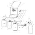
図3は、本実施例の炭酸ガス供給システム20を用いたビールサーバの一例を示す模式的な構成図である。図3において、炭酸ガス供給システム20から出力する設定圧炭酸ガス28、29、30はそれぞれ、ビールAを収容したビール樽31、ビールBを収容したビール樽32、ビールCを収容したビール樽33のそれぞれのディスペンスヘッド31a、32a、33aの炭酸ガス導入部31b、32b、33bに接続される。それらの炭酸ガスの圧力は、ビール樽31、32、33のそれぞれの適正圧力に調整することができる。例えば、設定圧炭酸ガス28の圧力をビール樽31に適正な基準圧力とする場合、圧力調整弁23の調整により設定圧炭酸ガス29の圧力は基準圧力-0.02MPaに、圧力調整弁24の調整により設定圧炭酸ガス30の圧力は基準圧力-0.04MPaと設定することができる。
FIG. 3 is a schematic configuration diagram showing an example of a beer server using the carbon dioxide
ビール樽31、32、33に加えられた炭酸ガス圧力により、それぞれのディスペンスヘッド31a、32a、33aのビール出力管31c、32c、33cからビールA、ビールB、ビールCが送出される。送出されたビールは、ビールサーバ34のそれぞれのビール入力口35、36、37からビールサーバ34の内部に導入され、ビールサーバ34内で冷却される。その後、ビールA、ビールB、ビールCのそれぞれのドラフトコック38、39、40のレバー操作により、それらの注出口に置かれたグラス内に抽出される。
なお、提供するビールの種類が4つ以上の場合は、減圧弁の出力側に接続する出力管の分岐数を増加し、増加した出力管に本発明の圧力調整弁を設置すればよい。
The carbon dioxide pressure applied to the beer barrels 31, 32, 33 causes beer A, beer B, and beer C to be delivered from the
In addition, when the number of types of beer to be provided is four or more, the number of branches of the output pipe connected to the output side of the pressure reducing valve may be increased, and the pressure regulating valve of the present invention may be installed in the increased output pipe.
以上のように、本実施例の炭酸ガス供給システムを用いれば、1つの炭酸ガスボンベを用いて多くの種類のビール樽に適切な圧力の炭酸ガスを供給することが可能となり、従来に比べ設置スペースや設置コストの削減が可能となる。 As described above, by using the carbon dioxide gas supply system of this embodiment, it is possible to supply carbon dioxide gas at an appropriate pressure to many types of beer kegs using one carbon dioxide gas cylinder, and it takes up less installation space than before. This makes it possible to reduce installation costs.
また、本発明の圧力調整弁及び炭酸ガス供給システムは、ビールサーバのみでなく、炭酸ガスの圧力を利用して飲料を供給する飲料供給装置において、1つの炭酸ガスボンベを用いてそれぞれの飲料容器に適した多種の炭酸ガス圧力を同時に供給することが可能となる Moreover, the pressure regulating valve and carbon dioxide gas supply system of the present invention can be applied not only to beer servers but also to beverage containers that use one carbon dioxide gas cylinder to supply beverages using the pressure of carbon dioxide gas. It becomes possible to simultaneously supply various types of suitable carbon dioxide gas pressures.
なお、本発明は上記の実施例に限定されるものではないことは言うまでもなく、目的や用途に応じて設計変更可能である。例えば、実施例に示した圧力調整弁のバルブ、調整ねじなどの構造や形状、炭酸ガス供給システムの形態等は一例にすぎず、目的に合わせて設計可能である。 It goes without saying that the present invention is not limited to the above embodiments, and the design can be changed depending on the purpose and use. For example, the structure and shape of the pressure regulating valve, the regulating screw, etc., the form of the carbon dioxide gas supply system, etc. shown in the embodiments are merely examples, and can be designed according to the purpose.
1 基準圧炭酸ガス
2 入力通路
3 基台部
4 蓋部
5、15 バルブ
6、16 コイルばね
7、17 調整ねじ
8、18 内部空間
9 出力通路
10、23、24 圧力調整弁
11、28、29、30 設定圧炭酸ガス
12 逆流圧調整弁
20 炭酸ガス供給システム
21 炭酸ガスボンベ
22 減圧弁
25、26、27 出力管
31、32、33 ビール樽
31a、32a、33a ディスペンスヘッド
31b、32b、33b 炭酸ガス導入部
31c、32c、33c ビール出力管
34 ビールサーバ
35、36、37 ビール入力口
38、39、40 ドラフトコック
1 Standard
Claims (4)
前記減圧弁側から前記飲料容器側へ向かう炭酸ガスの通路に設置された第1の圧力調整部と、
前記飲料容器側から前記減圧弁側へ向かう炭酸ガスの通路に設置された第2の圧力調整部と、を有し、
前記第1の圧力調整部と前記第2の圧力調整部は一体化された構造物として形成され、
前記第1及び第2の圧力調整部は、それぞれ、入力する炭酸ガスが通過する空隙の幅を調整可能なバルブと、前記バルブに前記空隙を閉じるような力を加えるコイルばねと、前記コイルばねを押す力を調整可能な調整機構と、を有し、
前記減圧弁側から入力された炭酸ガスの圧力を前記第1の圧力調整部により任意の圧力に減圧して前記飲料容器側に出力し、
前記飲料容器側から逆流する炭酸ガスを前記第2の圧力調整部を介して前記減圧弁側に導くことにより、前記飲料容器から逆流する炭酸ガスの圧力を調整可能に構成されている
ことを特徴とする圧力調整弁。 In a carbon dioxide gas supply system that supplies carbon dioxide gas to a beverage container containing a beverage in a beverage supply device that supplies beverages under the pressure of carbon dioxide gas via a pressure reducing valve connected to a carbon dioxide gas cylinder, the carbon dioxide gas supply system is connected to the output side of the pressure reducing valve. A pressure regulating valve configured to allow
a first pressure adjustment section installed in a carbon dioxide gas passage from the pressure reducing valve side to the beverage container side;
a second pressure adjustment part installed in a passage of carbon dioxide gas from the beverage container side to the pressure reducing valve side,
The first pressure adjustment section and the second pressure adjustment section are formed as an integrated structure,
The first and second pressure adjustment parts each include a valve that can adjust the width of a gap through which input carbon dioxide gas passes, a coil spring that applies a force to the valve to close the gap, and the coil spring. It has an adjustment mechanism that allows you to adjust the pressing force ,
The pressure of carbon dioxide gas input from the pressure reducing valve side is reduced to an arbitrary pressure by the first pressure regulator and output to the beverage container side;
The pressure of the carbon dioxide gas flowing back from the beverage container can be adjusted by guiding the carbon dioxide gas flowing back from the beverage container side to the pressure reducing valve side via the second pressure adjustment section.
A pressure regulating valve characterized by:
前記減圧弁側の炭酸ガスの通路は前記第1の圧力調整部の前記基台部の炭酸ガスの通路、及び前記第2の圧力調整部の前記空隙に導通し、
前記飲料容器側の炭酸ガスの通路は前記第1の圧力調整部の前記空隙、及び前記第2の圧力調整部の前記基台部の炭酸ガスの通路に導通していることを特徴とする請求項1に記載の圧力調整弁。 The first and second pressure adjustment parts each have a base part having a carbon dioxide gas passage in the center, and a lid part facing the base part and covering an outlet of the carbon dioxide gas passage, The coil spring applies a force to push the lid in the direction of the base, and the adjustment mechanism adjusts the width of the gap created between the base and the lid. configured to output carbon dioxide gas input into the carbon dioxide gas passage of the base portion,
The carbon dioxide gas passage on the pressure reducing valve side is connected to the carbon dioxide gas passage in the base part of the first pressure adjustment part and the gap of the second pressure adjustment part,
A claim characterized in that the carbon dioxide gas passage on the beverage container side communicates with the void of the first pressure adjustment part and the carbon dioxide gas passage of the base part of the second pressure adjustment part. The pressure regulating valve according to item 1 .
炭酸ガスボンベと、
前記炭酸ガスボンベに接続された減圧弁と、
前記減圧弁の出力側に接続された少なくとも1つの圧力調整弁と、を有し、
前記圧力調整弁は、
前記減圧弁側から前記飲料容器側へ向かう炭酸ガスの通路に設置された第1の圧力調整部と、
前記飲料容器側から前記減圧弁側へ向かう炭酸ガスの通路に設置された第2の圧力調整部と、を有し、
前記第1の圧力調整部と前記第2の圧力調整部は一体化された構造物として形成され、
前記第1及び第2の圧力調整部は、それぞれ、入力する炭酸ガスが通過する空隙の幅を調整可能なバルブと、前記バルブに前記空隙を閉じるような力を加えるコイルばねと、前記コイルばねを押す力を調整可能な調整機構と、を有し、
前記減圧弁側から入力された炭酸ガスの圧力を前記第1の圧力調整部により任意の圧力に減圧して前記飲料容器側に出力し、
前記飲料容器側から逆流する炭酸ガスを前記第2の圧力調整部を介して前記減圧弁側に導くことにより、前記飲料容器から逆流する炭酸ガスの圧力を調整することを特徴とする炭酸ガス供給システム。 A carbon dioxide gas supply system that supplies carbon dioxide gas to a beverage container containing a beverage of a beverage supply device that supplies beverages under the pressure of carbon dioxide gas,
carbon dioxide cylinder and
a pressure reducing valve connected to the carbon dioxide cylinder;
at least one pressure regulating valve connected to the output side of the pressure reducing valve;
The pressure regulating valve is
a first pressure adjustment section installed in a carbon dioxide gas passage from the pressure reducing valve side to the beverage container side;
a second pressure adjustment part installed in a passage of carbon dioxide gas from the beverage container side to the pressure reducing valve side,
The first pressure adjustment section and the second pressure adjustment section are formed as an integrated structure,
The first and second pressure adjustment parts each include a valve that can adjust the width of a gap through which input carbon dioxide gas passes, a coil spring that applies a force to the valve to close the gap, and the coil spring. It has an adjustment mechanism that allows you to adjust the pressing force ,
The pressure of carbon dioxide gas input from the pressure reducing valve side is reduced to an arbitrary pressure by the first pressure regulator and output to the beverage container side;
The carbon dioxide gas supply is characterized in that the pressure of the carbon dioxide gas flowing back from the beverage container is adjusted by guiding the carbon dioxide gas flowing back from the beverage container side to the pressure reducing valve side via the second pressure adjustment section. system.
According to claim 3, the pressure reducing valve has at least two output pipes branched and connected from the output side of the pressure reducing valve, and the pressure regulating valve is connected to at least one of the output pipes. The carbon dioxide supply system described .
Priority Applications (1)
| Application Number | Priority Date | Filing Date | Title |
|---|---|---|---|
| JP2019176736A JP7349133B2 (en) | 2019-09-27 | 2019-09-27 | Pressure regulating valve and carbon dioxide supply system |
Applications Claiming Priority (1)
| Application Number | Priority Date | Filing Date | Title |
|---|---|---|---|
| JP2019176736A JP7349133B2 (en) | 2019-09-27 | 2019-09-27 | Pressure regulating valve and carbon dioxide supply system |
Publications (2)
| Publication Number | Publication Date |
|---|---|
| JP2021054433A JP2021054433A (en) | 2021-04-08 |
| JP7349133B2 true JP7349133B2 (en) | 2023-09-22 |
Family
ID=75272082
Family Applications (1)
| Application Number | Title | Priority Date | Filing Date |
|---|---|---|---|
| JP2019176736A Active JP7349133B2 (en) | 2019-09-27 | 2019-09-27 | Pressure regulating valve and carbon dioxide supply system |
Country Status (1)
| Country | Link |
|---|---|
| JP (1) | JP7349133B2 (en) |
Families Citing this family (1)
| Publication number | Priority date | Publication date | Assignee | Title |
|---|---|---|---|---|
| JP2023096943A (en) * | 2021-12-27 | 2023-07-07 | アサヒビール株式会社 | Carbon dioxide supply device |
Citations (5)
| Publication number | Priority date | Publication date | Assignee | Title |
|---|---|---|---|---|
| JP2002068382A (en) | 2000-09-06 | 2002-03-08 | Bokuson Uesuto:Kk | In-barrel pressure regulating valve of beer dispenser |
| JP2002173196A (en) | 2000-12-05 | 2002-06-18 | Hoshizaki Electric Co Ltd | Soda water pouring machine and control method therefor |
| JP2003128193A (en) | 2001-10-29 | 2003-05-08 | Kyosan Denki Co Ltd | Sparkling beverage feeder |
| JP2005178853A (en) | 2003-12-22 | 2005-07-07 | Shinya Ofu | Carbon dioxide gas discharger and carbonated drink server |
| JP2016022969A (en) | 2014-07-18 | 2016-02-08 | 株式会社リード | Pressure regulator for beer barrel |
Family Cites Families (2)
| Publication number | Priority date | Publication date | Assignee | Title |
|---|---|---|---|---|
| JPS63111496U (en) * | 1987-01-09 | 1988-07-18 | ||
| JPH01182700A (en) * | 1988-01-09 | 1989-07-20 | Hamai Seisakusho:Kk | Pressure regulating on-off valve |
-
2019
- 2019-09-27 JP JP2019176736A patent/JP7349133B2/en active Active
Patent Citations (5)
| Publication number | Priority date | Publication date | Assignee | Title |
|---|---|---|---|---|
| JP2002068382A (en) | 2000-09-06 | 2002-03-08 | Bokuson Uesuto:Kk | In-barrel pressure regulating valve of beer dispenser |
| JP2002173196A (en) | 2000-12-05 | 2002-06-18 | Hoshizaki Electric Co Ltd | Soda water pouring machine and control method therefor |
| JP2003128193A (en) | 2001-10-29 | 2003-05-08 | Kyosan Denki Co Ltd | Sparkling beverage feeder |
| JP2005178853A (en) | 2003-12-22 | 2005-07-07 | Shinya Ofu | Carbon dioxide gas discharger and carbonated drink server |
| JP2016022969A (en) | 2014-07-18 | 2016-02-08 | 株式会社リード | Pressure regulator for beer barrel |
Also Published As
| Publication number | Publication date |
|---|---|
| JP2021054433A (en) | 2021-04-08 |
Similar Documents
| Publication | Publication Date | Title |
|---|---|---|
| EP3978424B1 (en) | Cooled beverage dispensing nozzle with in-nozzle mixing | |
| US20220297999A1 (en) | Beverage dispensing system, beverage container and pressurizing system for use in a beverage dispensing system or container | |
| US5303733A (en) | Pressure regulating unit for beverage dispensing system | |
| EP1261545B1 (en) | Enhanced flow controller for a beverage dispenser | |
| US20200300379A1 (en) | Gas valve | |
| US20110316175A1 (en) | Carbonation apparatus and method for forming a carbonated beverage | |
| AU2005211876A1 (en) | Method and device for gasifying water | |
| EP2897894B1 (en) | System for dispensing beverage | |
| US20040217131A1 (en) | Bar gun | |
| JP7349133B2 (en) | Pressure regulating valve and carbon dioxide supply system | |
| US20010032672A1 (en) | Enhanced flow controller for a beverage dispenser | |
| US8087428B1 (en) | High pressure inlet regulator | |
| US2389667A (en) | Fluid valve control | |
| US10654702B2 (en) | Valve assemblies and manually operable handle assemblies for beverage dispensing machines | |
| US20100264160A1 (en) | Multi-Stream Draught Beer Dispensing System | |
| US20120160330A1 (en) | System and method for continuously producing a liquid mixture | |
| US6401974B1 (en) | Versatile system for fountain beverage mixing | |
| JP2014201333A (en) | Automatic pressure adjusting device in beverage server system | |
| US20110061742A1 (en) | Cryogenic liquid cylinder manifold | |
| US8347780B2 (en) | Beverage air management dispensing system | |
| US20150240463A1 (en) | Arrangement for handling a liquid medium | |
| JP2022136028A (en) | Combination pressure regulator for cryogenic tanks | |
| JP4193722B2 (en) | Beverage supply equipment | |
| US20250353726A1 (en) | Beverage mixing and dispensing system and tap for use therein | |
| US167212A (en) | Improvement in air and gas or fluid regulators |
Legal Events
| Date | Code | Title | Description |
|---|---|---|---|
| A621 | Written request for application examination |
Free format text: JAPANESE INTERMEDIATE CODE: A621 Effective date: 20220728 |
|
| A977 | Report on retrieval |
Free format text: JAPANESE INTERMEDIATE CODE: A971007 Effective date: 20230322 |
|
| A131 | Notification of reasons for refusal |
Free format text: JAPANESE INTERMEDIATE CODE: A131 Effective date: 20230329 |
|
| A521 | Request for written amendment filed |
Free format text: JAPANESE INTERMEDIATE CODE: A523 Effective date: 20230526 |
|
| A521 | Request for written amendment filed |
Free format text: JAPANESE INTERMEDIATE CODE: A523 Effective date: 20230615 |
|
| TRDD | Decision of grant or rejection written | ||
| A01 | Written decision to grant a patent or to grant a registration (utility model) |
Free format text: JAPANESE INTERMEDIATE CODE: A01 Effective date: 20230830 |
|
| A61 | First payment of annual fees (during grant procedure) |
Free format text: JAPANESE INTERMEDIATE CODE: A61 Effective date: 20230904 |
|
| R150 | Certificate of patent or registration of utility model |
Ref document number: 7349133 Country of ref document: JP Free format text: JAPANESE INTERMEDIATE CODE: R150 |