JP7336658B2 - Presentation system, presentation system control method, program, and relay terminal - Google Patents

Presentation system, presentation system control method, program, and relay terminal Download PDF

Info

Publication number
JP7336658B2
JP7336658B2 JP2018226078A JP2018226078A JP7336658B2 JP 7336658 B2 JP7336658 B2 JP 7336658B2 JP 2018226078 A JP2018226078 A JP 2018226078A JP 2018226078 A JP2018226078 A JP 2018226078A JP 7336658 B2 JP7336658 B2 JP 7336658B2
Authority
JP
Japan
Prior art keywords
presentation
outdoor
unit
signal
facility
Prior art date
Legal status (The legal status is an assumption and is not a legal conclusion. Google has not performed a legal analysis and makes no representation as to the accuracy of the status listed.)
Active
Application number
JP2018226078A
Other languages
Japanese (ja)
Other versions
JP2020087369A (en
Inventor
秀晃 高橋
舞 珍坂
敬一 田中
Current Assignee (The listed assignees may be inaccurate. Google has not performed a legal analysis and makes no representation or warranty as to the accuracy of the list.)
Panasonic Intellectual Property Management Co Ltd
Original Assignee
Panasonic Intellectual Property Management Co Ltd
Priority date (The priority date is an assumption and is not a legal conclusion. Google has not performed a legal analysis and makes no representation as to the accuracy of the date listed.)
Filing date
Publication date
Application filed by Panasonic Intellectual Property Management Co Ltd filed Critical Panasonic Intellectual Property Management Co Ltd
Priority to JP2018226078A priority Critical patent/JP7336658B2/en
Priority to PCT/JP2019/042454 priority patent/WO2020110569A1/en
Publication of JP2020087369A publication Critical patent/JP2020087369A/en
Application granted granted Critical
Publication of JP7336658B2 publication Critical patent/JP7336658B2/en
Active legal-status Critical Current
Anticipated expiration legal-status Critical

Links

Images

Classifications

    • GPHYSICS
    • G08SIGNALLING
    • G08BSIGNALLING SYSTEMS, e.g. PERSONAL CALLING SYSTEMS; ORDER TELEGRAPHS; ALARM SYSTEMS
    • G08B17/00Fire alarms; Alarms responsive to explosion
    • GPHYSICS
    • G08SIGNALLING
    • G08BSIGNALLING SYSTEMS, e.g. PERSONAL CALLING SYSTEMS; ORDER TELEGRAPHS; ALARM SYSTEMS
    • G08B23/00Alarms responsive to unspecified undesired or abnormal conditions
    • GPHYSICS
    • G08SIGNALLING
    • G08BSIGNALLING SYSTEMS, e.g. PERSONAL CALLING SYSTEMS; ORDER TELEGRAPHS; ALARM SYSTEMS
    • G08B27/00Alarm systems in which the alarm condition is signalled from a central station to a plurality of substations

Landscapes

  • Business, Economics & Management (AREA)
  • Emergency Management (AREA)
  • Physics & Mathematics (AREA)
  • General Physics & Mathematics (AREA)
  • Alarm Systems (AREA)
  • Fire Alarms (AREA)

Description

本開示は、提示システム、提示システムの制御方法、プログラム、及び中継端末に関する。より詳細には、本開示は、施設で発生した異常を提示する提示システム、提示システムの制御方法、プログラム、及び中継端末に関する。 The present disclosure relates to a presentation system, a presentation system control method, a program, and a relay terminal. More specifically, the present disclosure relates to a presentation system that presents anomalies that have occurred in a facility, a presentation system control method, a program, and a relay terminal.

特許文献1には、例えば二階建ての住宅に設置される、無線式の屋外表示装置を備えた無線監視システムが記載されている。特許文献1に記載の無線監視システムでは、例えば、無線監視装置が無線火災センサからの火災検出電文を受信すると、この火災検出電文に対する発光制御電文を、無線中継器を経由して屋外表示装置に送信する。屋外表示装置は、無線監視装置からの発光制御電文に従って警告灯を点灯させる。 Patent Literature 1 describes a wireless monitoring system equipped with a wireless outdoor display device, which is installed, for example, in a two-story house. In the wireless monitoring system described in Patent Document 1, for example, when a wireless monitoring device receives a fire detection message from a wireless fire sensor, a light emission control message corresponding to the fire detection message is sent to an outdoor display device via a wireless repeater. Send. The outdoor display device lights the warning light according to the light emission control message from the wireless monitoring device.

特開2006-106995号公報JP 2006-106995 A

ところで、特許文献1に記載の無線監視システム(提示システム)では、住宅(施設)で発生した火災(異常)を近隣の住宅(他の施設)に通知することができなかった。 By the way, in the wireless monitoring system (presentation system) described in Patent Document 1, it was not possible to notify nearby houses (other facilities) of a fire (abnormality) that occurred in a house (facility).

本開示の目的は、施設で発生した異常を他の施設に通知することができる提示システム、提示システムの制御方法、プログラム、及び中継端末を提供することにある。 An object of the present disclosure is to provide a presentation system, a presentation system control method, a program, and a relay terminal capable of notifying other facilities of an abnormality that has occurred in a facility.

本開示の一態様に係る提示システムは、センサ端末で検知した異常を、戸外提示部にて提示する提示システムである。前記センサ端末は、特定領域に含まれる施設に設けられている。前記戸外提示部は、前記施設の戸外に設けられている。前記提示システムは、出力部を備える。前記出力部は、他の戸外提示部にて前記異常を提示するための連動提示信号を、前記他の戸外提示部に向けて出力する。前記他の戸外提示部は、前記特定領域に含まれる他の施設の戸外に設けられている。 A presentation system according to an aspect of the present disclosure is a presentation system that presents an abnormality detected by a sensor terminal using an outdoor presentation unit. The sensor terminal is provided in a facility included in the specific area. The outdoor presentation unit is provided outside the facility. The presentation system comprises an output unit. The output section outputs an interlocking presentation signal for presenting the abnormality in another outdoor presentation section toward the other outdoor presentation section. The other outdoor presentation unit is provided outdoors in another facility included in the specific area.

本開示の一態様に係る提示システムの制御方法は、センサ端末で検知した異常を、戸外提示部にて提示する提示システムの制御方法である。前記センサ端末は、特定領域に含まれる施設に設けられている。前記戸外提示部は、前記施設の戸外に設けられている。前記提示システムの制御方法は、他の戸外提示部にて前記異常を提示するための連動提示信号を、前記他の戸外提示部に向けて出力する処理を含む。前記他の戸外提示部は、前記特定領域に含まれる他の施設の戸外に設けられている。 A control method of a presentation system according to an aspect of the present disclosure is a control method of a presentation system that presents an abnormality detected by a sensor terminal in an outdoor presentation unit. The sensor terminal is provided in a facility included in the specific area. The outdoor presentation unit is provided outside the facility. The control method of the presentation system includes a process of outputting an interlocking presentation signal for presenting the abnormality in another outdoor presentation section to the other outdoor presentation section. The other outdoor presentation unit is provided outdoors in another facility included in the specific area.

本開示の一態様に係るプログラムは、コンピュータシステムに、上述の提示システムの制御方法を実行させるためのプログラムである。 A program according to an aspect of the present disclosure is a program for causing a computer system to execute the control method of the presentation system described above.

本開示の一態様に係る中継端末は、センサ端末で検知した異常を、戸外提示部にて提示する提示システムに用いられる中継端末である。前記センサ端末は、特定領域に含まれる施設に設けられている。前記戸外提示部は、前記施設の戸外に設けられている。前記中継端末は、他の戸外提示部にて前記異常を提示するための連動提示信号を中継する。前記他の戸外提示部は、前記特定領域に含まれる他の施設の戸外に設けられている。 A relay terminal according to an aspect of the present disclosure is a relay terminal used in a presentation system that presents an abnormality detected by a sensor terminal using an outdoor presentation unit. The sensor terminal is provided in a facility included in the specific area. The outdoor presentation unit is provided outside the facility. The relay terminal relays an interlocking presentation signal for presenting the abnormality in another outdoor presentation unit. The other outdoor presentation unit is provided outdoors in another facility included in the specific area.

本開示によれば、施設で発生した異常を他の施設に通知することができる、という利点がある。 According to the present disclosure, there is an advantage that it is possible to notify other facilities of an abnormality that has occurred in a facility.

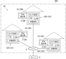
図1は、本開示の一実施形態に係る提示システムの適用例を説明する図である。FIG. 1 is a diagram illustrating an application example of a presentation system according to an embodiment of the present disclosure. 図2は、同上の提示システムに用いられるセンサ端末のブロック図である。FIG. 2 is a block diagram of a sensor terminal used in the same presentation system. 図3は、同上の提示システムに用いられる中継端末のブロック図である。FIG. 3 is a block diagram of a relay terminal used in the above presentation system. 図4は、同上の提示システムの動作を説明するシーケンス図である。FIG. 4 is a sequence diagram illustrating the operation of the presentation system; 図5は、本開示の一実施形態の変形例1に係る提示システムの動作を説明するシーケンス図である。FIG. 5 is a sequence diagram illustrating the operation of the presentation system according to Modification 1 of the embodiment of the present disclosure. 図6は、本開示の一実施形態の変形例2に係る提示システムの動作を説明するシーケンス図である。FIG. 6 is a sequence diagram illustrating operations of the presentation system according to Modification 2 of the embodiment of the present disclosure. 図7は、本開示の一実施形態の変形例3に係る提示システムの動作を説明するシーケンス図である。FIG. 7 is a sequence diagram illustrating the operation of the presentation system according to Modification 3 of the embodiment of the present disclosure. 図8は、本開示の一実施形態の変形例4に係る提示システムの動作を説明するシーケンス図である。FIG. 8 is a sequence diagram explaining the operation of the presentation system according to Modification 4 of the embodiment of the present disclosure. 図9は、本開示の一実施形態の変形例5に係る提示システムの模式図である。FIG. 9 is a schematic diagram of a presentation system according to Modification 5 of an embodiment of the present disclosure.

(実施形態)
(1)概要
以下、実施形態に係る提示システム10の概要について、図1を参照して説明する。
(embodiment)
(1) Overview An overview of the presentation system 10 according to the embodiment will be described below with reference to FIG.

実施形態に係る提示システム10は、例えば、図1に示すように、複数の提示システム10の各々を連動させる連動提示システム20に用いられる。連動提示システム20は、複数(実施形態では3つ)の提示システム10と、サーバ4と、を備えている。ただし、サーバ4については、連動提示システム20に含まれていてもよいし、含まれていなくてもよい。つまり、連動提示システム20は、少なくとも複数の提示システム10を備えていればよい。さらに、提示システム10の個数も3つに限らず、2つであってもよいし、4つ以上であってもよい。 The presentation system 10 according to the embodiment is used, for example, in an interlocking presentation system 20 that interlocks a plurality of presentation systems 10, as shown in FIG. The linked presentation system 20 includes a plurality of (three in the embodiment) presentation systems 10 and a server 4 . However, the server 4 may or may not be included in the linked presentation system 20 . In other words, the linked presentation system 20 may include at least a plurality of presentation systems 10 . Furthermore, the number of presentation systems 10 is not limited to three, and may be two or four or more.

提示システム10は、図1に示すように、センサ端末1と、戸外提示部2と、中継端末3と、を備えている。 The presentation system 10 includes a sensor terminal 1, an outdoor presentation unit 2, and a relay terminal 3, as shown in FIG.

センサ端末1は、例えば、施設100に設けられた警報器(住警器)である。施設100は、例えば、戸建て住宅である。施設100は、特定領域200に含まれている。特定領域200は、例えば、市区町村等の行政区画である。センサ端末1は、施設100内の空間の天井、又は壁等に取り付けられる。センサ端末1は、施設100で発生した異常を検知する検知機能と、検知機能にて異常を検知した場合に報知する報知機能と、を有し、異常に関する報知動作を行う。センサ端末1は、上記異常として、例えば施設100で発生した火災を検知し、火災に関する報知動作を行う。すなわち、センサ端末1は、火災発生時において警報音等を出力する。なお、センサ端末1の検知対象は、火災に限らず、例えば、ガス漏れ、又は不完全燃焼によるCO(一酸化炭素)の発生等であってもよい。 The sensor terminal 1 is, for example, an alarm (residential alarm) provided in the facility 100 . Facility 100 is, for example, a detached house. Facility 100 is included in specific area 200 . The specific area 200 is, for example, an administrative division such as a municipality. The sensor terminal 1 is attached to the ceiling, wall, or the like of the space within the facility 100 . The sensor terminal 1 has a detection function for detecting an abnormality that has occurred in the facility 100 and a notification function for notifying when an abnormality is detected by the detection function, and performs an abnormality notification operation. The sensor terminal 1 detects, for example, a fire that has broken out in the facility 100 as the abnormality, and performs a notification operation regarding the fire. That is, the sensor terminal 1 outputs an alarm sound or the like when a fire occurs. The object to be detected by the sensor terminal 1 is not limited to fire, and may be, for example, CO (carbon monoxide) generated due to gas leakage or incomplete combustion.

戸外提示部2は、例えば、施設100の戸外(屋外)に設けられた表示灯である。戸外提示部2は、例えば、施設100の玄関の外壁に取り付けられている。戸外提示部2は、センサ端末1の検知結果に応じて、センサ端末1又は中継端末3から出力される提示信号に従って点灯する。したがって、戸外提示部2は、センサ端末1及び中継端末3の少なくとも一方と通信可能であることが好ましい。 The outdoor presentation unit 2 is, for example, a display lamp provided outside the facility 100 (outdoors). The outdoor presentation unit 2 is attached to the outer wall of the entrance of the facility 100, for example. The outdoor presentation unit 2 lights according to a presentation signal output from the sensor terminal 1 or the relay terminal 3 according to the detection result of the sensor terminal 1 . Therefore, it is preferable that the outdoor presentation unit 2 can communicate with at least one of the sensor terminal 1 and the relay terminal 3 .

中継端末3は、例えば、HEMS(Home Energy Management System)のコントローラである。中継端末3は、施設100に設けられた複数の機器と通信可能である。複数の機器は、例えば、照明器具、空調機器等を含む。中継端末3は、更に、センサ端末1及び戸外提示部2とも通信可能である。また、中継端末3は、インターネット等のネットワーク5を介してサーバ4と通信可能である。中継端末3は、サーバ4を介して、他の施設100に設けられた他の中継端末3とも通信可能である。 The relay terminal 3 is, for example, a controller of HEMS (Home Energy Management System). The relay terminal 3 can communicate with a plurality of devices provided in the facility 100 . The plurality of devices includes, for example, lighting fixtures, air conditioners, and the like. The relay terminal 3 can also communicate with the sensor terminal 1 and the outdoor presentation unit 2 . Also, the relay terminal 3 can communicate with the server 4 via a network 5 such as the Internet. The relay terminal 3 can also communicate with other relay terminals 3 provided in other facilities 100 via the server 4 .

実施形態に係る提示システム10は、センサ端末1で検知した異常(ここでは火災)を、戸外提示部2にて提示する提示システム10である。センサ端末1は、特定領域200に含まれる施設100に設けられている。戸外提示部2は、施設100の戸外に設けられている。提示システム10は、出力部(例えばセンサ端末1の通信部12)を備える。出力部は、他の戸外提示部2にて異常を提示するための連動提示信号を、他の戸外提示部2に向けて出力する。他の戸外提示部2は、特定領域200に含まれる他の施設100の戸外に設けられている。 The presentation system 10 according to the embodiment is a presentation system 10 that presents an abnormality (here, fire) detected by the sensor terminal 1 using the outdoor presentation unit 2 . A sensor terminal 1 is provided in a facility 100 included in a specific area 200 . The outdoor presentation unit 2 is provided outside the facility 100 . The presentation system 10 includes an output unit (for example, the communication unit 12 of the sensor terminal 1). The output unit outputs an interlocking presentation signal for presenting an abnormality in another outdoor presentation unit 2 toward the other outdoor presentation unit 2 . Another outdoor presentation unit 2 is provided outside of another facility 100 included in the specific area 200 .

実施形態に係る中継端末3は、センサ端末1で検知した異常を、戸外提示部2にて提示する提示システム10に用いられる中継端末3である。センサ端末1は、特定領域200に含まれる施設100に設けられている。戸外提示部2は、施設100の戸外に設けられている。中継端末3は、他の戸外提示部2にて異常を提示するための連動提示信号を中継する。他の戸外提示部2は、特定領域200に含まれる他の施設100の戸外に設けられている。 The relay terminal 3 according to the embodiment is a relay terminal 3 used in a presentation system 10 that presents an abnormality detected by the sensor terminal 1 using the outdoor presentation unit 2 . A sensor terminal 1 is provided in a facility 100 included in a specific area 200 . The outdoor presentation unit 2 is provided outside the facility 100 . The relay terminal 3 relays an interlocking presentation signal for presenting an abnormality in another outdoor presentation unit 2 . Another outdoor presentation unit 2 is provided outside of another facility 100 included in the specific area 200 .

実施形態に係る提示システム10及び中継端末3では、センサ端末1が施設100で発生した異常を検知した場合に、他の戸外提示部2にて異常を提示するための連動提示信号を直接的に、又は間接的に、他の戸外提示部2に出力している。そのため、連動提示信号に従って他の戸外提示部2が異常を提示することにより、施設100で発生した異常を他の施設100に通知することができる。 In the presentation system 10 and the relay terminal 3 according to the embodiment, when the sensor terminal 1 detects an abnormality that has occurred in the facility 100, the interlocking presentation signal for presenting the abnormality in the other outdoor presentation unit 2 is directly generated. , or indirectly, output to another outdoor presentation unit 2 . Therefore, by the other outdoor presentation unit 2 presenting the abnormality according to the interlocking presentation signal, the other facility 100 can be notified of the abnormality that has occurred in the facility 100 .

(2)構成
以下、実施形態に係る提示システム10を用いた連動提示システム20の構成について、図1~図3を参照して説明する。実施形態に係る連動提示システム20は、図1に示すように、複数(実施形態では3つ)の提示システム10と、サーバ4と、を備えている。また、複数の提示システム10の各々は、図1に示すように、センサ端末1と、戸外提示部2と、中継端末3と、を備えている。
(2) Configuration The configuration of an interlocked presentation system 20 using the presentation system 10 according to the embodiment will be described below with reference to FIGS. 1 to 3. FIG. A linked presentation system 20 according to the embodiment includes, as shown in FIG. 1 , a plurality of (three in the embodiment) presentation systems 10 and a server 4 . Each of the plurality of presentation systems 10 includes a sensor terminal 1, an outdoor presentation unit 2, and a relay terminal 3, as shown in FIG.

以下の説明において、複数の提示システム10を区別する場合には、複数の提示システム10の各々を、「提示システム10A,10B,10C」ともいう。さらに、複数のセンサ端末1を区別する場合には、複数のセンサ端末1の各々を、「センサ端末1A,1B,1C」ともいう。また、複数の戸外提示部2を区別する場合には、複数の戸外提示部2の各々を、「戸外提示部2A,2B,2C」ともいう。また、複数の中継端末3を区別する場合には、複数の中継端末3の各々を、「中継端末3A,3B,3C」ともいう。さらに、複数の提示システム10が設けられた複数の施設100を区別する場合には、複数の施設100の各々を、「施設101,102,103」ともいう。 In the following description, when distinguishing the plurality of presentation systems 10, each of the plurality of presentation systems 10 is also referred to as "presentation systems 10A, 10B, and 10C." Furthermore, when distinguishing between a plurality of sensor terminals 1, each of the plurality of sensor terminals 1 is also referred to as "sensor terminals 1A, 1B, and 1C." Moreover, when distinguishing the several outdoor presentation part 2, each of the several outdoor presentation part 2 is also called "outdoor presentation part 2A, 2B, 2C." Moreover, when distinguishing between a plurality of relay terminals 3, each of the plurality of relay terminals 3 is also referred to as "relay terminals 3A, 3B, and 3C." Furthermore, when distinguishing between a plurality of facilities 100 provided with a plurality of presentation systems 10, each of the plurality of facilities 100 is also referred to as "facility 101, 102, 103."

(2.1)センサ端末
センサ端末1は、例えば、施設100に設けられた警報器(住警器)である。センサ端末1は、施設100で発生した異常(ここでは火災)を検知する検知機能と、検知機能によって異常を検知した場合に報知する報知機能と、を有している。センサ端末1は、図2に示すように、制御部11と、通信部12と、検知部13と、報知部14と、記憶部15と、バッテリと、を備えている。バッテリは、例えば、リチウム電池である。センサ端末1は、バッテリから供給される電力によって動作する。
(2.1) Sensor Terminal The sensor terminal 1 is, for example, an alarm (house alarm) provided in the facility 100 . The sensor terminal 1 has a detection function of detecting an abnormality (here, a fire) occurring in the facility 100 and a notification function of notifying when an abnormality is detected by the detection function. The sensor terminal 1 includes, as shown in FIG. 2, a control unit 11, a communication unit 12, a detection unit 13, a notification unit 14, a storage unit 15, and a battery. The battery is, for example, a lithium battery. The sensor terminal 1 operates with power supplied from a battery.

制御部11は、例えば、1以上のプロセッサ及び1以上のメモリを有するコンピュータシステムを主構成とする。そして、コンピュータシステムのメモリに記録されたプログラムを、コンピュータシステムのプロセッサが実行することにより、制御部11の機能が実現される。プログラムは、メモリに予め記録されていてもよいし、インターネット等の電気通信回線を通じて、又はメモリカード等の非一時的な記録媒体に記録されて提供されてもよい。 The control unit 11 is mainly composed of, for example, a computer system having one or more processors and one or more memories. The functions of the control unit 11 are realized by the processor of the computer system executing the program recorded in the memory of the computer system. The program may be prerecorded in a memory, or may be provided by being recorded in a non-temporary recording medium such as a memory card or through an electric communication line such as the Internet.

制御部11は、検知部13からの検知信号(後述する)に基づいて、火災の発生の有無を判断する。例えば、制御部11は、検知信号が示す電圧レベルが予め定められた閾値以上である場合に、火災が発生したと判断する。制御部11は、火災が発生したと判断した場合、報知部14から警報音を出力させる。警報音が音声メッセージである場合には、制御部11は、記憶部15に記憶されているメッセージデータに基づいて、音声メッセージに対応した音声信号を生成する。そして、報知部14は、制御部11が生成した音声信号に基づいた音声メッセージを出力する。 The control unit 11 determines whether or not a fire has occurred based on a detection signal (described later) from the detection unit 13 . For example, the control unit 11 determines that a fire has occurred when the voltage level indicated by the detection signal is equal to or higher than a predetermined threshold. When determining that a fire has occurred, the control unit 11 causes the notification unit 14 to output an alarm sound. If the alarm sound is a voice message, the control section 11 generates a voice signal corresponding to the voice message based on the message data stored in the storage section 15 . Then, the notification unit 14 outputs a voice message based on the voice signal generated by the control unit 11 .

通信部12は、例えば、戸外提示部2及び中継端末3と通信を行うための通信インターフェースを含む。通信部12は、戸外提示部2及び中継端末3との間で、例えば920MHz帯の電波を利用した無線通信を行う。通信部12は、戸外提示部2(2A)との無線通信により、少なくとも戸外提示部2に対して提示信号を送信(出力)する。提示信号は、施設100において異常(ここでは火災)が発生したことを戸外提示部2にて提示するための信号である。通信部12は、更に、他の戸外提示部としての戸外提示部2B,2Cとも通信可能である。通信部12は、少なくとも戸外提示部2B,2Cに対して連動提示信号を送信(出力)する。連動提示信号は、施設100において発生した異常(ここでは火災)を、施設100とは別の他の施設100(102,102)に設けられた戸外提示部2B,2Cにて提示するための信号である。さらに、通信部12は、中継端末3との無線通信により、少なくとも中継端末3に対して検知部13の検知信号を送信する。ここで、通信部12から送信される無線信号には、戸外提示部2及び中継端末3の各々を識別するための識別情報が含まれている。識別情報は、例えば、戸外提示部2及び中継端末3の各々に割り当てられたIPアドレス、MACアドレス、又は名称等である。 The communication unit 12 includes, for example, a communication interface for communicating with the outdoor presentation unit 2 and the relay terminal 3 . The communication unit 12 performs wireless communication with the outdoor presentation unit 2 and the relay terminal 3 using radio waves in the 920 MHz band, for example. The communication unit 12 transmits (outputs) a presentation signal to at least the outdoor presentation unit 2 through wireless communication with the outdoor presentation unit 2 (2A). The presentation signal is a signal for presenting by the outdoor presentation unit 2 that an abnormality (here, a fire) has occurred in the facility 100 . The communication unit 12 can also communicate with the outdoor presentation units 2B and 2C as other outdoor presentation units. The communication unit 12 transmits (outputs) the linked presentation signal to at least the outdoor presentation units 2B and 2C. The interlocking presentation signal is a signal for presenting an abnormality (fire in this case) that has occurred in the facility 100 by the outdoor presentation units 2B and 2C provided in the facilities 100 (102, 102) different from the facility 100. is. Furthermore, the communication unit 12 transmits the detection signal of the detection unit 13 to at least the relay terminal 3 through wireless communication with the relay terminal 3 . Here, the wireless signal transmitted from the communication unit 12 includes identification information for identifying each of the outdoor presentation unit 2 and the relay terminal 3 . The identification information is, for example, an IP address, a MAC address, a name, or the like assigned to each of the outdoor presentation unit 2 and the relay terminal 3 .

検知部13は、警報音の発報対象となる火災に関する情報を検知する機能(検知機能)を有している。検知部13は、例えば、煙を検知する光電式のセンサを含む。したがって、検知部13が検知する情報は、煙に関する情報である。検知部13は、発光部及び受光部を有している。発光部は、例えば発光ダイオード(LED)を含む。受光部は、例えばフォトダイオードを含む。ここで、検知部13の筐体内部は、ラビリンス構造になっている。そして、発光部及び受光部は、筐体のラビリンス内において、受光部の受光面が発光部の光軸上から外れるように配置されている。火災の発生時には、筐体に設けられた孔を通じて、煙がラビリンス内に導入され得る。 The detection unit 13 has a function (detection function) of detecting information about a fire to be notified by an alarm sound. The detection unit 13 includes, for example, a photoelectric sensor that detects smoke. Therefore, the information detected by the detection unit 13 is information about smoke. The detector 13 has a light emitter and a light receiver. The light emitter includes, for example, a light emitting diode (LED). The light receiving section includes, for example, a photodiode. Here, the inside of the housing of the detection unit 13 has a labyrinth structure. The light emitting unit and the light receiving unit are arranged in the labyrinth of the housing such that the light receiving surface of the light receiving unit is off the optical axis of the light emitting unit. In the event of a fire, smoke can be introduced into the labyrinth through holes provided in the housing.

筐体のラビリンス内に煙が存在しない場合、発光部の照射光は、受光部の受光面にほとんど到達しない。一方、筐体のラビリンス内に煙が存在する場合、発光部の照射光が煙によって散乱し、散乱した光の一部が受光部の受光面に到達する。つまり、検知部13は、煙によって散乱された発光部の照射光を受光部で受光する。検知部13は、受光部で受光した光量に応じた電圧レベルを示す電気信号(検知信号)を制御部11に出力する。 If there is no smoke in the labyrinth of the housing, the light emitted from the light emitter hardly reaches the light receiving surface of the light receiver. On the other hand, when smoke exists in the labyrinth of the housing, the light emitted from the light emitting unit is scattered by the smoke, and part of the scattered light reaches the light receiving surface of the light receiving unit. In other words, the detection unit 13 receives the irradiation light from the light emitting unit scattered by the smoke at the light receiving unit. The detection unit 13 outputs to the control unit 11 an electric signal (detection signal) indicating a voltage level corresponding to the amount of light received by the light receiving unit.

報知部14は、施設100で発生した異常を検知部13が検知した場合に、異常の発生を報知する機能(報知機能)を有している。報知部14は、例えば、スピーカ及び発光部を含む。発光部は、例えば、赤色LEDを含む。報知部14は、制御部11にて火災が発生していると判断した場合に、スピーカを介して、例えば「ビュービュー火事です」等の警報音の発報を行う。さらに、報知部14は、制御部11にて火災が発生していると判断した場合に、赤色LEDを点滅(又は点灯)させる。 The notification unit 14 has a function (notification function) to notify the occurrence of an abnormality when the detection unit 13 detects an abnormality that has occurred in the facility 100 . The notification unit 14 includes, for example, a speaker and a light emitting unit. The light emitting unit includes, for example, a red LED. When the control unit 11 determines that a fire has occurred, the notification unit 14 issues an alarm sound such as "View-view fire" through the speaker. Furthermore, when the control unit 11 determines that a fire has occurred, the notification unit 14 causes the red LED to flash (or light up).

記憶部15は、ROM(Read Only Memory)、RAM(Random Access Memory)、又はEEPROM(Electrically Erasable Programmable Read Only Memory)等から選択されるデバイスで構成される。記憶部15は、警報音として出力する音声メッセージに係るメッセージデータを記憶している。さらに、記憶部15は、各戸外提示部2(2A,2B,2C)、及び各中継端末3(3A,3B,3C)にそれぞれ割り当てられた識別情報を記憶している。 The storage unit 15 is configured by a device selected from ROM (Read Only Memory), RAM (Random Access Memory), EEPROM (Electrically Erasable Programmable Read Only Memory), or the like. The storage unit 15 stores message data relating to voice messages to be output as alarm sounds. Further, the storage unit 15 stores identification information assigned to each outdoor presentation unit 2 (2A, 2B, 2C) and each relay terminal 3 (3A, 3B, 3C).

(2.2)中継端末
中継端末3は、例えば、HEMSのコントローラである。中継端末3は、施設100に設けられた複数の機器と通信可能である。中継端末3は、更に、センサ端末1、及び他の中継端末3(3B,3C)とも通信可能である。中継端末3は、図3に示すように、制御部31と、第1通信部32と、第2通信部33と、記憶部34と、表示部35と、を備えている。
(2.2) Relay Terminal The relay terminal 3 is, for example, a HEMS controller. The relay terminal 3 can communicate with a plurality of devices provided in the facility 100 . The relay terminal 3 can also communicate with the sensor terminal 1 and other relay terminals 3 (3B, 3C). The relay terminal 3 includes a control unit 31, a first communication unit 32, a second communication unit 33, a storage unit 34, and a display unit 35, as shown in FIG.

制御部31は、例えば、1以上のプロセッサ及び1以上のメモリを有するコンピュータシステムを主構成とする。そして、コンピュータシステムのメモリに記録されたプログラムを、コンピュータシステムのプロセッサが実行することにより、制御部31の機能が実現される。プログラムは、メモリに予め記録されていてもよいし、インターネット等の電気通信回線を通じて、又はメモリカード等の非一時的な記録媒体に記録されて提供されてもよい。 The control unit 31 is mainly composed of, for example, a computer system having one or more processors and one or more memories. The functions of the control unit 31 are realized by the processor of the computer system executing the program recorded in the memory of the computer system. The program may be prerecorded in a memory, or may be provided by being recorded in a non-temporary recording medium such as a memory card or through an electric communication line such as the Internet.

第1通信部32は、センサ端末1と通信を行うための通信インターフェースを含む。第1通信部32は、センサ端末1の通信部12との間で、例えば920MHz帯の電波を利用した無線通信を行う。第1通信部32は、通信部12との無線通信により、少なくとも検知部13の検知信号を受信する。 The first communication unit 32 includes a communication interface for communicating with the sensor terminal 1 . The first communication unit 32 performs wireless communication with the communication unit 12 of the sensor terminal 1 using radio waves in the 920 MHz band, for example. The first communication unit 32 receives at least the detection signal of the detection unit 13 through wireless communication with the communication unit 12 .

第2通信部33は、インターネット等のネットワーク5を介してサーバ4と通信を行うための通信インターフェースを含む。さらに、第2通信部33は、サーバ4を介して他の中継端末3(3B,3C)の第2通信部33とも通信可能である。この構成によれば、中継端末3がセンサ端末1から取得した検知部13の検知信号を、サーバ4又は他の中継端末3に送信することもできる。 The second communication unit 33 includes a communication interface for communicating with the server 4 via the network 5 such as the Internet. Furthermore, the second communication unit 33 can communicate with the second communication units 33 of the other relay terminals 3 (3B, 3C) via the server 4 as well. According to this configuration, the relay terminal 3 can transmit the detection signal of the detection unit 13 acquired from the sensor terminal 1 to the server 4 or another relay terminal 3 .

記憶部34は、ROM、RAM、又はEEPROM等から選択されるデバイスで構成される。記憶部34は、各センサ端末1(1A,1B,1C)、及び他の中継端末3(3B,3C)にそれぞれ割り当てられた識別情報を記憶している。 The storage unit 34 is configured by a device selected from ROM, RAM, EEPROM, or the like. The storage unit 34 stores identification information assigned to each sensor terminal 1 (1A, 1B, 1C) and other relay terminals 3 (3B, 3C).

表示部35は、例えば液晶ディスプレイ、及び有機EL(Electro Luminescence)ディスプレイのような薄型のディスプレイ装置である。表示部35は、例えば、センサ端末1から取得した検知部13の検知結果(火災の発生)を表示する。 The display unit 35 is a thin display device such as a liquid crystal display and an organic EL (Electro Luminescence) display. The display unit 35 displays, for example, the detection result (occurrence of fire) of the detection unit 13 acquired from the sensor terminal 1 .

(2.3)戸外提示部
戸外提示部2は、例えば、施設100の玄関に設けられた玄関表示灯である。戸外提示部2は、例えば、センサ端末1と通信を行うための通信インターフェースを含む。戸外提示部2は、センサ端末1との間で、例えば920MHz帯の電波を利用した無線通信を行う。戸外提示部2は、センサ端末1との無線通信により、センサ端末1から提示信号を受信する。そして、戸外提示部2は、受信した提示信号に従って点灯し、火災の発生を提示する。
(2.3) Outdoor Presentation Unit The outdoor presentation unit 2 is, for example, an entrance indicator light provided at the entrance of the facility 100 . The outdoor presentation unit 2 includes, for example, a communication interface for communicating with the sensor terminal 1 . The outdoor presentation unit 2 performs wireless communication with the sensor terminal 1 using radio waves in the 920 MHz band, for example. The outdoor presentation unit 2 receives the presentation signal from the sensor terminal 1 through wireless communication with the sensor terminal 1 . Then, the outdoor presentation unit 2 lights up in accordance with the received presentation signal to present the occurrence of fire.

(3)動作
次に、実施形態に係る提示システム10を用いた連動提示システム20の動作について、図4を参照して説明する。以下では、特定領域200に含まれる複数の施設101~103のうち施設101において異常(火災)が発生した場合を例示するが、施設102又は施設103において異常が発生した場合も同様である。そのため、施設102又は施設103において異常が発生した場合については説明を省略する。
(3) Operation Next, operation of the linked presentation system 20 using the presentation system 10 according to the embodiment will be described with reference to FIG. In the following, the case where an abnormality (fire) occurs in the facility 101 among the plurality of facilities 101 to 103 included in the specific area 200 will be exemplified. Therefore, a description of the case where an abnormality occurs in the facility 102 or the facility 103 will be omitted.

以下の説明では、施設100において異常が発生しているため、施設102,103が「他の施設」、センサ端末1B,1Cが「他のセンサ端末」、戸外提示部2B,2Cが「他の戸外提示部」、中継端末3B,3Cが「他の中継端末」となる。 In the following description, since an abnormality has occurred in the facility 100, the facilities 102 and 103 are "other facilities", the sensor terminals 1B and 1C are "other sensor terminals", and the outdoor presentation units 2B and 2C are "other "outdoor presentation unit" and relay terminals 3B and 3C are "other relay terminals".

施設101において火災が発生すると、センサ端末1Aが火災の発生を検知する(ステップS11)。センサ端末1Aは、火災の発生を検知すると、施設101の戸外に設けられた戸外提示部2Aに対して提示信号を送信(出力)する(ステップS12)。さらに、センサ端末1Aは、施設102の戸外に設けられた戸外提示部2B、及び施設103の戸外に設けられた戸外提示部2Cに対して連動提示信号を送信(出力)する(ステップS13)。 When a fire breaks out in the facility 101, the sensor terminal 1A detects the fire breakout (step S11). When detecting the occurrence of a fire, the sensor terminal 1A transmits (outputs) a presentation signal to the outdoor presentation unit 2A provided outside the facility 101 (step S12). Further, the sensor terminal 1A transmits (outputs) an interlocking presentation signal to the outdoor presentation unit 2B provided outside the facility 102 and the outdoor presentation unit 2C provided outside the facility 103 (step S13).

施設101の戸外に設けられた戸外提示部2Aは、センサ端末1Aからの提示信号に従って点灯し、施設101での異常の発生を提示する(ステップS14)。さらに、施設102,103の戸外に設けられた戸外提示部2B,2Cは、センサ端末1Aからの連動提示信号に従って点灯し、施設101での異常の発生を提示する(ステップS15,S16)。 The outdoor presentation unit 2A provided outside the facility 101 lights up in accordance with the presentation signal from the sensor terminal 1A, and presents the occurrence of an abnormality in the facility 101 (step S14). Furthermore, the outdoor display units 2B and 2C provided outside the facilities 102 and 103 light up in accordance with the interlocking presentation signal from the sensor terminal 1A to present the occurrence of abnormality in the facility 101 (steps S15 and S16).

実施形態に係る提示システム10Aでは、施設101に設けられたセンサ端末1Aが施設101で発生した異常を検知すると、施設102,103の戸外に設けられた戸外提示部2B,2Cにて異常を提示している。したがって、施設101で発生した異常を、施設102,103(の住人)に通知することができる。 In the presentation system 10A according to the embodiment, when the sensor terminal 1A provided in the facility 101 detects an abnormality that has occurred in the facility 101, the outdoor presentation units 2B and 2C provided outside the facilities 102 and 103 present the abnormality. are doing. Therefore, it is possible to notify (the residents of) facilities 102 and 103 of an abnormality that has occurred in facility 101 .

さらに、実施形態に係る提示システム10Aでは、センサ端末1Aが、戸外提示部2B,2Cに対して直接的に、連動提示信号を送信(出力)している。つまり、実施形態に係る提示システム10Aでは、センサ端末1Aの通信部12が出力部である。これにより、連動提示信号を戸外提示部2B,2Cに伝達するための中継端末が不要であり、提示システム10Aの簡略化を図ることができる。 Furthermore, in the presentation system 10A according to the embodiment, the sensor terminal 1A directly transmits (outputs) the interlocked presentation signal to the outdoor presentation units 2B and 2C. That is, in the presentation system 10A according to the embodiment, the communication unit 12 of the sensor terminal 1A is the output unit. This eliminates the need for a relay terminal for transmitting the interlocking presentation signal to the outdoor presentation units 2B and 2C, thereby simplifying the presentation system 10A.

なお、図4に示すシーケンス図において、センサ端末1Aは、戸外提示部2Aに対して提示信号を送信した後に、戸外提示部2B,2Cに対して連動提示信号を送信している。これに対して、センサ端末1Aは、戸外提示部2B,2Cに対して連動提示信号を送信した後に、戸外提示部2Aに対して提示信号を送信してもよいし、同時に送信してもよい。さらに、実施形態では、提示信号と連動提示信号とが別々であるが、1つの信号で兼用してもよい。 In the sequence diagram shown in FIG. 4, the sensor terminal 1A transmits the interlocking presentation signal to the outdoor presentation units 2B and 2C after transmitting the presentation signal to the outdoor presentation unit 2A. On the other hand, the sensor terminal 1A may transmit the presentation signal to the outdoor presentation unit 2A after transmitting the linked presentation signal to the outdoor presentation units 2B and 2C, or may transmit the presentation signal at the same time. . Furthermore, in the embodiment, the presentation signal and the linked presentation signal are separate, but one signal may be used for both.

(4)変形例
上述の実施形態は、本開示の様々な実施形態の一つに過ぎない。上述の実施形態は、本開示の目的を達成できれば、設計等に応じて種々の変更が可能である。また、提示システム10Aと同様の機能は、提示システム10Aの制御方法、コンピュータプログラム、又はコンピュータプログラムを記録した非一時的な記録媒体等で具現化されてもよい。
(4) Modifications The above-described embodiment is just one of various embodiments of the present disclosure. The above-described embodiments can be modified in various ways according to design and the like as long as the object of the present disclosure can be achieved. Also, functions similar to those of the presentation system 10A may be embodied by a control method of the presentation system 10A, a computer program, or a non-temporary recording medium recording the computer program.

一態様に係る提示システム10Aの制御方法は、センサ端末1Aで検知した異常を、戸外提示部2Aにて提示する提示システム10Aの制御方法である。センサ端末1Aは、特定領域200に含まれる施設101に設けられている。戸外提示部2Aは、施設101の戸外に設けられている。提示システム10Aの制御方法は、戸外提示部2B,2C(他の戸外提示部)にて異常を提示するための連動提示信号を、戸外提示部2B,2Cに向けて出力する処理を含む。戸外提示部2B,2Cは、特定領域200に含まれる施設102,103(他の施設)の戸外に設けられている。 A control method of the presentation system 10A according to one aspect is a control method of the presentation system 10A in which the outdoor presentation unit 2A presents an abnormality detected by the sensor terminal 1A. The sensor terminal 1A is provided in the facility 101 included in the specific area 200. As shown in FIG. The outdoor presentation unit 2A is provided outside the facility 101 . The control method of the presentation system 10A includes a process of outputting an interlocking presentation signal for presenting an abnormality in the outdoor presentation units 2B and 2C (other outdoor presentation units) to the outdoor presentation units 2B and 2C. Outdoor presentation units 2B and 2C are provided outdoors of facilities 102 and 103 (other facilities) included in specific area 200 .

一態様に係るプログラムは、コンピュータシステムに、上述の提示システム10Aの制御方法を実行させるためのプログラムである。 A program according to one aspect is a program for causing a computer system to execute the control method of the presentation system 10A described above.

以下、上述の実施形態の変形例を列挙する。以下に説明する変形例は、適宜組み合わせて適用可能である。 Modifications of the above-described embodiment are listed below. Modifications described below can be applied in combination as appropriate.

本開示における提示システム10(10A,10B,10C)は、コンピュータシステムを含んでいる。コンピュータシステムは、ハードウェアとしてのプロセッサ及びメモリを主構成とする。コンピュータシステムのメモリに記録されたプログラムをプロセッサが実行することによって、本開示における提示システム10としての機能が実現される。プログラムは、コンピュータシステムのメモリに予め記録されてもよく、電気通信回線を通じて提供されてもよく、コンピュータシステムで読み取り可能なメモリカード、光学ディスク、ハードディスクドライブ等の非一時的記録媒体に記録されて提供されてもよい。コンピュータシステムのプロセッサは、半導体集積回路(IC)又は大規模集積回路(LSI)を含む1ないし複数の電子回路で構成される。ここでいうIC又はLSI等の集積回路は、集積の度合いによって呼び方が異なっており、システムLSI、VLSI(Very Large Scale Integration)、又はULSI(Ultra Large Scale Integration)と呼ばれる集積回路を含む。さらに、LSIの製造後にプログラムされる、FPGA(Field-Programmable Gate Array)、又はLSI内部の接合関係の再構成若しくはLSI内部の回路区画の再構成が可能な論理デバイスについても、プロセッサとして採用することができる。複数の電子回路は、1つのチップに集約されていてもよいし、複数のチップに分散して設けられていてもよい。複数のチップは、1つの装置に集約されていてもよいし、複数の装置に分散して設けられていてもよい。ここでいうコンピュータシステムは、1以上のプロセッサ及び1以上のメモリを有するマイクロコントローラを含む。したがって、マイクロコントローラについても、半導体集積回路又は大規模集積回路を含む1ないし複数の電子回路で構成される。 The presentation system 10 (10A, 10B, 10C) in the present disclosure includes a computer system. A computer system is mainly composed of a processor and a memory as hardware. The functions of the presentation system 10 in the present disclosure are realized by the processor executing a program recorded in the memory of the computer system. The program may be recorded in advance in the memory of the computer system, may be provided through an electric communication line, or may be recorded in a non-temporary recording medium such as a computer system-readable memory card, optical disk, or hard disk drive. may be provided. A processor in a computer system consists of one or more electronic circuits, including semiconductor integrated circuits (ICs) or large scale integrated circuits (LSIs). The integrated circuit such as IC or LSI referred to here is called differently depending on the degree of integration, and includes integrated circuits called system LSI, VLSI (Very Large Scale Integration), or ULSI (Ultra Large Scale Integration). In addition, a field-programmable gate array (FPGA) that is programmed after the LSI is manufactured, or a logic device capable of reconfiguring the bonding relationship inside the LSI or reconfiguring the circuit partitions inside the LSI may also be adopted as the processor. can be done. A plurality of electronic circuits may be integrated into one chip, or may be distributed over a plurality of chips. A plurality of chips may be integrated in one device, or may be distributed in a plurality of devices. A computer system, as used herein, includes a microcontroller having one or more processors and one or more memories. Accordingly, the microcontroller also consists of one or more electronic circuits including semiconductor integrated circuits or large scale integrated circuits.

複数の装置に分散されている提示システム10の少なくとも一部の機能が、1つの筐体内に集約されていてもよい。例えば、センサ端末1と戸外提示部2と中継端末3とに分散されている提示システム10の一部の機能が、1つの筐体内に集約されていてもよい。さらに、提示システム10の少なくとも一部の機能、例えば、中継端末3の一部の機能がクラウド(クラウドコンピューティング)等によって実現されてもよい。 At least some of the functionality of presentation system 10 that is distributed across multiple devices may be consolidated within a single housing. For example, some functions of the presentation system 10 distributed among the sensor terminal 1, the outdoor presentation unit 2, and the relay terminal 3 may be integrated in one housing. Furthermore, at least part of the functions of the presentation system 10, for example, part of the functions of the relay terminal 3 may be realized by the cloud (cloud computing) or the like.

(4.1)変形例1
上述の実施形態では、センサ端末1Aが、連動提示信号を戸外提示部2B,2Cに直接的に送信(出力)しているが、例えば、戸外提示部2Aが、連動提示信号を戸外提示部2B,2Cに送信(出力)してもよい。言い換えると、出力部(センサ端末1の通信部12)は、戸外提示部2Aを介して間接的に、連動提示信号を戸外提示部2B,2C(他の戸外提示部)に出力してもよい。さらに言い換えると、出力部は、提示信号及び連動提示信号を戸外提示部2Aに出力してもよい。変形例1では、戸外提示部2Aが中継端末である。
(4.1) Modification 1
In the above-described embodiment, the sensor terminal 1A directly transmits (outputs) the interlocked presentation signal to the outdoor presentation units 2B and 2C. , 2C. In other words, the output unit (the communication unit 12 of the sensor terminal 1) may indirectly output the linked presentation signal to the outdoor presentation units 2B and 2C (other outdoor presentation units) via the outdoor presentation unit 2A. . In other words, the output section may output the presentation signal and the linked presentation signal to the outdoor presentation section 2A. In Modification 1, the outdoor presentation unit 2A is a relay terminal.

以下、変形例1に係る提示システム10及び連動提示システム20について、図5を参照して説明する。変形例1に係る提示システム10及び連動提示システム20は、複数の戸外提示部2A~2C間で通信可能である点を除いて、上述の実施形態に係る提示システム10及び連動提示システム20と同様であり、同一の構成要素には同一の符号を付して説明を省略する。 The presentation system 10 and the linked presentation system 20 according to Modification 1 will be described below with reference to FIG. The presentation system 10 and the interlocked presentation system 20 according to Modification 1 are the same as the presentation system 10 and the interlocked presentation system 20 according to the above-described embodiment, except that communication is possible between the plurality of outdoor presentation units 2A to 2C. , and the same components are denoted by the same reference numerals, and the description thereof is omitted.

変形例1に係る提示システム10及び連動提示システム20では、複数(ここでは3つ)の戸外提示部2A~2C間で通信可能である。複数の戸外提示部2A~2C間における通信は、例えば920MHz帯の電波を利用した無線通信である。 In the presentation system 10 and the linked presentation system 20 according to Modification 1, communication is possible between the plurality (here, three) of the outdoor presentation units 2A to 2C. Communication among the plurality of outdoor display units 2A to 2C is wireless communication using radio waves in the 920 MHz band, for example.

変形例1に係る連動提示システム20では、戸外提示部2Aは、連携先となる他の戸外提示部2B,2Cの識別情報を記憶しており、この識別情報に対応して連動提示信号を出力する。具体的には、戸外提示部2Aは、異常発生時において、他の戸外提示部2B,2Cの識別情報と連動提示信号とを含む無線信号を出力する。 In the interlocking presentation system 20 according to Modification 1, the outdoor presentation unit 2A stores the identification information of the other outdoor presentation units 2B and 2C to be linked, and outputs the interlocking presentation signal corresponding to this identification information. do. Specifically, when an abnormality occurs, the outdoor presentation unit 2A outputs a radio signal including the identification information of the other outdoor presentation units 2B and 2C and the interlocking presentation signal.

次に、変形例1に係る提示システム10を用いた連動提示システム20の動作について、図5を参照して説明する。以下では、特定領域200に含まれる複数の施設101~103のうち施設101において異常(火災)が発生した場合を例示するが、施設102又は施設103において異常が発生した場合も同様である。そのため、施設102又は施設103において異常が発生した場合については説明を省略する。 Next, the operation of the linked presentation system 20 using the presentation system 10 according to Modification 1 will be described with reference to FIG. In the following, the case where an abnormality (fire) occurs in the facility 101 among the plurality of facilities 101 to 103 included in the specific area 200 will be exemplified. Therefore, a description of the case where an abnormality occurs in the facility 102 or the facility 103 will be omitted.

施設101において火災が発生すると、センサ端末1Aが火災の発生を検知する(ステップS21)。センサ端末1Aは、火災の発生を検知すると、施設101の戸外に設けられた戸外提示部2Aに対して提示信号及び連動提示信号を送信(出力)する(ステップS22)。戸外提示部2Aは、センサ端末1Aから受信した連動提示信号を、施設102,103の戸外に設けられた戸外提示部2B,2Cに送信(出力)する(ステップS23)。 When a fire breaks out in the facility 101, the sensor terminal 1A detects the fire breakout (step S21). When detecting the occurrence of a fire, the sensor terminal 1A transmits (outputs) a presentation signal and an interlocked presentation signal to the outdoor presentation unit 2A provided outside the facility 101 (step S22). The outdoor presentation unit 2A transmits (outputs) the interlocked presentation signal received from the sensor terminal 1A to the outdoor presentation units 2B and 2C provided outside the facilities 102 and 103 (step S23).

施設101の戸外に設けられた戸外提示部2Aは、センサ端末1Aから受信した提示信号に従って点灯し、施設101での異常の発生を提示する(ステップS24)。さらに、施設102,103の戸外に設けられた戸外提示部2B,2Cは、戸外提示部2Aから受信した連動提示信号に従って点灯し、施設101での異常の発生を提示する(ステップS25,S26)。 The outdoor presentation unit 2A provided outside the facility 101 lights up in accordance with the presentation signal received from the sensor terminal 1A, and presents the occurrence of an abnormality in the facility 101 (step S24). Further, the outdoor presentation units 2B and 2C provided outdoors in the facilities 102 and 103 light up in accordance with the interlocking presentation signal received from the outdoor presentation unit 2A to present the occurrence of an abnormality in the facility 101 (steps S25 and S26). .

変形例1に係る提示システム10Aでは、施設101に設けられたセンサ端末1Aが施設101で発生した異常を検知すると、施設102,103の戸外に設けられた戸外提示部2B,2Cにて異常を提示している。したがって、施設101で発生した異常を、施設102,103(の住人)に通知することができる。 In the presentation system 10A according to Modification 1, when the sensor terminal 1A provided in the facility 101 detects an abnormality that has occurred in the facility 101, the outdoor presentation units 2B and 2C provided outside the facilities 102 and 103 indicate the abnormality. are presenting. Therefore, it is possible to notify (the residents of) facilities 102 and 103 of an abnormality that has occurred in facility 101 .

さらに、変形例1に係る提示システム10Aでは、センサ端末1Aから送信された連動提示信号を戸外提示部2Aが中継している。そのため、例えば、センサ端末1Aと戸外提示部2B,2Cとの距離が離れている場合でも、戸外提示部2Aを介して連動提示信号を戸外提示部2B,2Cに伝達することができる。 Furthermore, in the presentation system 10A according to Modification 1, the outdoor presentation unit 2A relays the interlocked presentation signal transmitted from the sensor terminal 1A. Therefore, for example, even when the sensor terminal 1A and the outdoor presentation units 2B and 2C are far apart, the interlocking presentation signal can be transmitted to the outdoor presentation units 2B and 2C via the outdoor presentation unit 2A.

各施設100において複数のセンサ端末1が設けられていてもよい。この構成において、センサ端末1が住警器である場合には、提示信号及び連動提示信号を出力するセンサ端末1は、火災を検知した住警器であってもよいし、親機となる住警器であってもよい。この場合、火災を検知した住警器又は親機となる住警器は、戸外提示部2Aに割り当てられた識別情報を記憶しており、この識別情報に対応して提示信号及び連動提示信号を出力する。 A plurality of sensor terminals 1 may be provided in each facility 100 . In this configuration, when the sensor terminal 1 is a residential alarm, the sensor terminal 1 that outputs the presentation signal and the interlocking presentation signal may be a residential alarm that has detected a fire, or may be a residential alarm serving as a master unit. It can be an alarm. In this case, the residential alarm that has detected the fire or the residential alarm serving as the master unit stores the identification information assigned to the outdoor presentation unit 2A, and outputs the presentation signal and the interlocking presentation signal corresponding to this identification information. Output.

(4.2)変形例2
上述の実施形態では、センサ端末1Aが、連動提示信号を戸外提示部2B,2Cに直接的に送信(出力)しているが、例えば、施設102,103に設けられたセンサ端末1B,1Cが、連動提示信号を戸外提示部2B,2Cに送信(出力)してもよい。言い換えると、出力部(センサ端末1の通信部12)は、センサ端末1B,1C(他のセンサ端末)を介して間接的に、連動提示信号を戸外提示部2B,2C(他の戸外提示部)に出力してもよい。さらに言い換えると、出力部(センサ端末1Aの通信部12)は、連動提示信号をセンサ端末1B,1C(他のセンサ端末)に出力し、センサ端末1B,1Cは、連動提示信号を戸外提示部2B,2Cに出力してもよい。変形例2では、センサ端末1B,1Cが中継端末である。
(4.2) Modification 2
In the above-described embodiment, the sensor terminal 1A directly transmits (outputs) the interlocked presentation signal to the outdoor presentation units 2B and 2C. , the interlocking presentation signal may be transmitted (output) to the outdoor presentation units 2B and 2C. In other words, the output unit (the communication unit 12 of the sensor terminal 1) indirectly sends the interlocking presentation signal to the outdoor presentation units 2B and 2C (other outdoor presentation units) via the sensor terminals 1B and 1C (other outdoor presentation units). ). In other words, the output unit (communication unit 12 of sensor terminal 1A) outputs the interlocked presentation signal to sensor terminals 1B and 1C (other sensor terminals), and sensor terminals 1B and 1C output the interlocked presentation signal to the outdoor presentation unit. You may output to 2B and 2C. In modification 2, sensor terminals 1B and 1C are relay terminals.

以下、変形例2に係る提示システム10について、図6を参照して説明する。変形例2に係る提示システム10及び連動提示システム20は、複数のセンサ端末1A~1C間で通信可能である点を除いて、上述の実施形態に係る提示システム10及び連動提示システム20と同様であり、同一の構成要素には同一の符号を付して説明を省略する。 The presentation system 10 according to Modification 2 will be described below with reference to FIG. The presentation system 10 and the interlocked presentation system 20 according to Modification 2 are similar to the presentation system 10 and the interlocked presentation system 20 according to the above-described embodiment, except that communication is possible between the plurality of sensor terminals 1A to 1C. Identical components are denoted by the same reference numerals, and descriptions thereof are omitted.

変形例2に係る提示システム10及び連動提示システム20では、複数(ここでは3つ)のセンサ端末1A~1C間で通信可能である。複数のセンサ端末1A~1C間における通信は、例えば420MHz帯の電波を利用した無線通信である。 In the presentation system 10 and the linked presentation system 20 according to Modification 2, communication is possible between a plurality of (here, three) sensor terminals 1A to 1C. Communication among the plurality of sensor terminals 1A to 1C is wireless communication using radio waves in the 420 MHz band, for example.

変形例2に係る連動提示システム20では、センサ端末1Aは、連携先となる他のセンサ端末1B,1Cの識別情報を記憶しており、この識別情報に対応して連動提示信号を出力する。具体的には、センサ端末1Aは、異常発生時において、他のセンサ端末1B,1Cの識別情報と連動提示信号とを含む無線信号を出力する。 In the interlocking presentation system 20 according to Modification 2, the sensor terminal 1A stores the identification information of the other sensor terminals 1B and 1C to be the cooperation destinations, and outputs the interlocking presentation signal corresponding to this identification information. Specifically, when an abnormality occurs, the sensor terminal 1A outputs a radio signal including identification information of the other sensor terminals 1B and 1C and an interlocking presentation signal.

次に、変形例2に係る提示システム10を用いた連動提示システム20の動作について、図6を参照して説明する。以下では、特定領域200に含まれる複数の施設101~103のうち施設101において異常(火災)が発生した場合を例示するが、施設102又は施設103において異常が発生した場合も同様である。そのため、施設102又は施設103において異常が発生した場合については説明を省略する。 Next, the operation of the linked presentation system 20 using the presentation system 10 according to Modification 2 will be described with reference to FIG. In the following, the case where an abnormality (fire) occurs in the facility 101 among the plurality of facilities 101 to 103 included in the specific area 200 will be exemplified. Therefore, a description of the case where an abnormality occurs in the facility 102 or the facility 103 will be omitted.

施設101において火災が発生すると、センサ端末1Aが火災の発生を検知する(ステップS31)。センサ端末1Aは、火災の発生を検知すると、施設102,103に設けられたセンサ端末1B,1Cに対して連動提示信号を送信(出力)する(ステップS32)。さらに、センサ端末1Aは、施設101の戸外に設けられた戸外提示部2Aに対して提示信号を送信(出力)する(ステップS33)。センサ端末1B,1Cは、センサ端末1Aから受信した連動提示信号を、施設102,103の戸外に設けられた戸外提示部2B,2Cに送信する(ステップS34,S35)。 When a fire breaks out in the facility 101, the sensor terminal 1A detects the fire breakout (step S31). When detecting the occurrence of fire, the sensor terminal 1A transmits (outputs) an interlocking presentation signal to the sensor terminals 1B and 1C provided in the facilities 102 and 103 (step S32). Furthermore, the sensor terminal 1A transmits (outputs) a presentation signal to the outdoor presentation unit 2A provided outside the facility 101 (step S33). The sensor terminals 1B and 1C transmit the linked presentation signal received from the sensor terminal 1A to the outdoor presentation units 2B and 2C provided outside the facilities 102 and 103 (steps S34 and S35).

施設101の戸外に設けられた戸外提示部2Aは、センサ端末1Aから受信した提示信号に従って点灯し、施設101での異常の発生を提示する(ステップS36)。さらに、施設102,103の戸外に設けられた戸外提示部2B,2Cは、センサ端末1B,1Cから受信した連動提示信号に従って点灯し、施設101での異常の発生を提示する(ステップS37,S38)。 The outdoor presentation unit 2A provided outside the facility 101 lights according to the presentation signal received from the sensor terminal 1A, and presents the occurrence of an abnormality in the facility 101 (step S36). Furthermore, the outdoor presentation units 2B and 2C provided outdoors in the facilities 102 and 103 light up in accordance with the interlocking presentation signals received from the sensor terminals 1B and 1C to present the occurrence of an abnormality in the facility 101 (steps S37 and S38). ).

変形例2に係る提示システム10Aでは、施設101に設けられたセンサ端末1Aが施設101で発生した異常を検知すると、施設102,103の戸外に設けられた戸外提示部2B,2Cにて異常を提示している。したがって、施設101で発生した異常を、施設102,103(の住人)に通知することができる。 In the presentation system 10A according to Modification 2, when the sensor terminal 1A provided in the facility 101 detects an abnormality that has occurred in the facility 101, the outdoor presentation units 2B and 2C provided outside the facilities 102 and 103 indicate the abnormality. are presenting. Therefore, it is possible to notify (the residents of) facilities 102 and 103 of an abnormality that has occurred in facility 101 .

さらに、変形例2に係る提示システム10Aでは、センサ端末1Aから送信された連動提示信号をセンサ端末1B,1Cが中継している。そのため、例えば、センサ端末1Aと戸外提示部2B,2Cとの距離が離れている場合でも、センサ端末1B,1Cを介して連動提示信号を戸外提示部2B,2Cに伝達することができる。 Furthermore, in the presentation system 10A according to Modification 2, the sensor terminals 1B and 1C relay the linked presentation signal transmitted from the sensor terminal 1A. Therefore, for example, even when the sensor terminal 1A and the outdoor presentation units 2B and 2C are far apart, the interlocking presentation signal can be transmitted to the outdoor presentation units 2B and 2C via the sensor terminals 1B and 1C.

なお、図6に示すシーケンス図において、センサ端末1Aは、センサ端末1B,1Cに対して連動提示信号を送信した後に、戸外提示部2Aに対して提示信号を送信している。これに対して、センサ端末1Aは、戸外提示部2Aに対して提示信号を送信した後に、センサ端末1B,1Cに対して連動提示信号を送信してもよいし、同時に送信してもよい。さらに、図6に示すシーケンス図において、センサ端末1Bが戸外提示部2Bに対して連動提示信号を送信した後に、センサ端末1Cが戸外提示部2Cに対して連動提示信号を送信している。これに対して、センサ端末1Cが戸外提示部2Cに対して連動提示信号を送信した後に、センサ端末1Bが戸外提示部2Bに対して連動提示信号を送信してもよいし、同時に送信してもよい。 In the sequence diagram shown in FIG. 6, the sensor terminal 1A transmits the presentation signal to the outdoor presentation unit 2A after transmitting the linked presentation signal to the sensor terminals 1B and 1C. On the other hand, the sensor terminal 1A may transmit the interlocking presentation signal to the sensor terminals 1B and 1C after transmitting the presentation signal to the outdoor presentation unit 2A, or may transmit them at the same time. Further, in the sequence diagram shown in FIG. 6, after sensor terminal 1B transmits the interlocked presentation signal to outdoor presentation unit 2B, sensor terminal 1C transmits the interlocked presentation signal to outdoor presentation unit 2C. On the other hand, sensor terminal 1B may transmit the interlocked presentation signal to outdoor presentation unit 2B after sensor terminal 1C transmits the interlocked presentation signal to outdoor presentation unit 2C, or may transmit the interlocked presentation signal to outdoor presentation unit 2B at the same time. good too.

各施設100において複数のセンサ端末1が設けられていてもよい。この構成において、センサ端末1が住警器である場合には、提示信号及び連動提示信号を出力するセンサ端末1は、火災を検知した住警器であってもよいし、親機となる住警器であってもよい。この場合、火災を検知した住警器又は親機となる住警器は、戸外提示部2Aに割り当てられた識別情報を記憶しており、この識別情報に対応して提示信号を出力する。さらに、火災を検知した住警器又は親機となる住警器は、他のセンサ端末1(住警器)に割り当てられた識別情報を記憶しており、この識別情報に対応して連動提示信号を出力する。 A plurality of sensor terminals 1 may be provided in each facility 100 . In this configuration, when the sensor terminal 1 is a residential alarm, the sensor terminal 1 that outputs the presentation signal and the interlocking presentation signal may be a residential alarm that has detected a fire, or may be a residential alarm serving as a master unit. It can be an alarm. In this case, the residential alarm that has detected the fire or the residential alarm serving as the master unit stores the identification information assigned to the outdoor presentation unit 2A, and outputs the presentation signal corresponding to this identification information. In addition, the residential alarm that has detected the fire or the residential alarm serving as the master unit stores identification information assigned to another sensor terminal 1 (residential alarm). Output a signal.

(4.3)変形例3
上述の実施形態では、センサ端末1Aが、連動提示信号を戸外提示部2B,2Cに直接的に送信(出力)しているが、例えば、施設101に設けられた中継端末3Aが、連動提示信号を戸外提示部2B,2Cに送信(出力)してもよい。言い換えると、中継端末3Aが出力部(第1通信部32)を含み、出力部は、連動提示信号を戸外提示部2B,2C(他の戸外提示部)に出力してもよい。以下、変形例3に係る提示システム10及び連動提示システム20について、図7を参照して説明する。変形例3に係る提示システム10及び連動提示システム20は、中継端末3が戸外提示部2と通信可能である点を除いて、上述の実施形態に係る提示システム10及び連動提示システム20と同様であり、同一の構成要素には同一の符号を付して説明を省略する。
(4.3) Modification 3
In the above embodiment, the sensor terminal 1A directly transmits (outputs) the interlocked presentation signal to the outdoor presentation units 2B and 2C. may be transmitted (output) to the outdoor presentation units 2B and 2C. In other words, relay terminal 3A may include an output unit (first communication unit 32), and the output unit may output the linked presentation signal to outdoor presentation units 2B and 2C (other outdoor presentation units). The presentation system 10 and the linked presentation system 20 according to Modification 3 will be described below with reference to FIG. The presentation system 10 and the interlocked presentation system 20 according to Modification 3 are the same as the presentation system 10 and the interlocked presentation system 20 according to the above-described embodiment, except that the relay terminal 3 can communicate with the outdoor presentation unit 2. Identical components are denoted by the same reference numerals, and descriptions thereof are omitted.

変形例3に係る提示システム10及び連動提示システム20では、中継端末3が戸外提示部2(2A,2B,2C)とも通信可能である。中継端末3の第1通信部32は、戸外提示部2との間で、例えば920MHz帯の電波を利用した無線通信を行う。 In the presentation system 10 and the linked presentation system 20 according to Modification 3, the relay terminal 3 can also communicate with the outdoor presentation units 2 (2A, 2B, 2C). The first communication unit 32 of the relay terminal 3 performs wireless communication with the outdoor presentation unit 2 using radio waves in the 920 MHz band, for example.

変形例3に係る連動提示システム20では、中継端末3Aは、連携先となる他の戸外提示部2B,2Cの識別情報を記憶しており、この識別情報に対応して連動提示信号を出力する。具体的には、中継端末3Aは、異常発生時において、他の戸外提示部2B,2Cの識別情報と連動提示信号とを含む無線信号を出力する。 In the interlocking presentation system 20 according to Modification 3, the relay terminal 3A stores the identification information of the other outdoor presentation units 2B and 2C to be linked, and outputs the interlocking presentation signal corresponding to this identification information. . Specifically, the relay terminal 3A outputs a radio signal including the identification information of the other outdoor presentation units 2B and 2C and the linked presentation signal when an abnormality occurs.

次に、変形例3に係る提示システム10を用いた連動提示システム20の動作について、図7を参照して説明する。以下では、特定領域200に含まれる複数の施設101~103のうち施設101において異常(火災)が発生した場合を例示するが、施設102又は施設103において異常が発生した場合も同様である。そのため、施設102又は施設103において異常が発生した場合については説明を省略する。 Next, the operation of the linked presentation system 20 using the presentation system 10 according to Modification 3 will be described with reference to FIG. In the following, the case where an abnormality (fire) occurs in the facility 101 among the plurality of facilities 101 to 103 included in the specific area 200 will be exemplified. Therefore, a description of the case where an abnormality occurs in the facility 102 or the facility 103 will be omitted.

施設101において火災が発生すると、センサ端末1Aが火災の発生を検知する(ステップS41)。センサ端末1Aは、火災の発生を検知すると、中継端末3Aに対して異常信号(検知部13の検知信号)を送信する(ステップS42)。中継端末3Aは、センサ端末1Aから異常信号を受信すると、提示信号及び連動提示信号を生成する。そして、中継端末3Aは、施設101の戸外に設けられた戸外提示部2Aに提示信号を送信すると共に、施設102,103の戸外に設けられた戸外提示部2B,2Cに連動提示信号を送信する(ステップS43,44)。つまり、変形例3に係る提示システム10Aでは、中継端末3Aの第1通信部32が出力部である。 When a fire breaks out in the facility 101, the sensor terminal 1A detects the fire breakout (step S41). When the sensor terminal 1A detects the occurrence of fire, it transmits an abnormality signal (detection signal of the detection unit 13) to the relay terminal 3A (step S42). Upon receiving the abnormal signal from the sensor terminal 1A, the relay terminal 3A generates a presentation signal and an interlocked presentation signal. The relay terminal 3A transmits the presentation signal to the outdoor presentation unit 2A provided outside the facility 101, and also transmits the linked presentation signal to the outdoor presentation units 2B and 2C provided outside the facilities 102 and 103. (Steps S43, 44). That is, in the presentation system 10A according to Modification 3, the first communication unit 32 of the relay terminal 3A is the output unit.

施設101の戸外に設けられた戸外提示部2Aは、中継端末3Aから受信した提示信号に従って点灯し、施設101での異常の発生を提示する(ステップS45)。さらに、施設102,103の戸外に設けられた戸外提示部2B,2Cは、中継端末3Aから受信した連動提示信号に従って点灯し、施設101での異常の発生を提示する(ステップS46,S47)。 The outdoor presentation unit 2A provided outside the facility 101 lights according to the presentation signal received from the relay terminal 3A, and presents the occurrence of an abnormality in the facility 101 (step S45). Further, the outdoor presentation units 2B and 2C provided outside the facilities 102 and 103 light up in accordance with the interlocking presentation signal received from the relay terminal 3A to present the occurrence of abnormality in the facility 101 (steps S46 and S47).

変形例3に係る提示システム10Aでは、施設101に設けられたセンサ端末1Aが施設101で発生した異常を検知すると、施設102,103の戸外に設けられた戸外提示部2B,2Cにて異常を提示している。したがって、施設101で発生した異常を、施設102,103(の住人)に通知することができる。 In the presentation system 10A according to Modification 3, when the sensor terminal 1A provided in the facility 101 detects an abnormality that has occurred in the facility 101, the outdoor presentation units 2B and 2C provided outside the facilities 102 and 103 indicate the abnormality. are presenting. Therefore, it is possible to notify (the residents of) facilities 102 and 103 of an abnormality that has occurred in facility 101 .

また、変形例3に係る提示システム10Aでは、センサ端末1Aから送信された連動提示信号を中継端末3Aが中継している。これにより、センサ端末1Aが連動提示信号を戸外提示部2B,2Cに出力する場合に比べて、センサ端末1Aの処理負担を軽減することができる。 Further, in the presentation system 10A according to Modification 3, the relay terminal 3A relays the linked presentation signal transmitted from the sensor terminal 1A. As a result, the processing load on the sensor terminal 1A can be reduced compared to when the sensor terminal 1A outputs the interlocked presentation signal to the outdoor presentation units 2B and 2C.

なお、図7に示すシーケンス図において、中継端末3Aは、戸外提示部2Aに対して提示信号を送信した後に、戸外提示部2B,2Cに対して連動提示信号を送信している。これに対して、中継端末3Aは、戸外提示部2B,2Cに対して連動提示信号を送信した後に、戸外提示部2Aに対して提示信号を送信してもよいし、同時に送信してもよい。さらに、変形例3では、提示信号と連動提示信号とが別々であるが、1つの信号で兼用してもよい。 In the sequence diagram shown in FIG. 7, the relay terminal 3A transmits the interlocking presentation signal to the outdoor presentation units 2B and 2C after transmitting the presentation signal to the outdoor presentation unit 2A. On the other hand, the relay terminal 3A may transmit the presentation signal to the outdoor presentation unit 2A after transmitting the linked presentation signal to the outdoor presentation units 2B and 2C, or may transmit the presentation signal at the same time. . Furthermore, although the presentation signal and the interlocking presentation signal are separate in Modification 3, one signal may be used for both.

各施設100において複数のセンサ端末1が設けられていてもよい。この構成において、センサ端末1が住警器である場合には、異常信号を出力するセンサ端末1は、火災を検知した住警器であってもよいし、親機となる住警器であってもよい。この場合、火災を検知した住警器又は親機となる住警器は、中継端末3Aに割り当てられた識別情報を記憶しており、この識別情報に対応して異常信号を出力する。 A plurality of sensor terminals 1 may be provided in each facility 100 . In this configuration, when the sensor terminal 1 is a home alarm, the sensor terminal 1 that outputs an abnormal signal may be a home alarm that detects a fire, or a home alarm that serves as a master unit. may In this case, the fire alarm that has detected the fire or the home alarm serving as the master unit stores the identification information assigned to the relay terminal 3A, and outputs an abnormal signal corresponding to this identification information.

(4.4)変形例4
上述の実施形態では、センサ端末1Aが、連動提示信号を戸外提示部2B,2Cに直接的に送信(出力)しているが、例えば、施設102,103に設けられた中継端末3B,3Cが、連動提示信号を戸外提示部2B,2Cに送信(出力)してもよい。言い換えると、中継端末3Aが出力部(第2通信部33)を含み、出力部は、連動提示信号を中継端末3B,3C(他の中継端末)に出力し、中継端末3B,3Cは、連動提示信号を戸外提示部2B,2C(他の戸外提示部)に出力してもよい。
(4.4) Modification 4
In the above-described embodiment, the sensor terminal 1A directly transmits (outputs) the interlocked presentation signal to the outdoor presentation units 2B and 2C. , the interlocking presentation signal may be transmitted (output) to the outdoor presentation units 2B and 2C. In other words, the relay terminal 3A includes an output unit (second communication unit 33), the output unit outputs the interlocking presentation signal to the relay terminals 3B and 3C (other relay terminals), and the relay terminals 3B and 3C The presentation signal may be output to the outdoor presentation units 2B and 2C (other outdoor presentation units).

以下、変形例4に係る提示システム10及び連動提示システム20について、図8を参照して説明する。変形例4に係る提示システム10及び連動提示システム20は、中継端末3が戸外提示部2と通信可能である点を除いて、上述の実施形態に係る提示システム10及び連動提示システム20と同様であり、同一の構成要素には同一の符号を付して説明を省略する。 The presentation system 10 and the linked presentation system 20 according to Modification 4 will be described below with reference to FIG. 8 . The presentation system 10 and the interlocked presentation system 20 according to Modification 4 are the same as the presentation system 10 and the interlocked presentation system 20 according to the above-described embodiment, except that the relay terminal 3 can communicate with the outdoor presentation unit 2. Identical components are denoted by the same reference numerals, and descriptions thereof are omitted.

変形例4に係る提示システム10及び連動提示システム20では、上述したように、中継端末3Aは、サーバ4を介して中継端末3B,3C(他の中継端末)と通信可能である。つまり、中継端末3Aでは、第2通信部33が、サーバ4を介して中継端末3B,3Cの第2通信部33と通信可能である。 In the presentation system 10 and the linked presentation system 20 according to Modification 4, the relay terminal 3A can communicate with the relay terminals 3B and 3C (other relay terminals) via the server 4 as described above. That is, the second communication unit 33 of the relay terminal 3A can communicate with the second communication units 33 of the relay terminals 3B and 3C via the server 4 .

変形例4に係る連動提示システム20では、中継端末3Aは、異常発生時において、自己に割り当てられた識別情報と連動提示信号とを含む無線信号をサーバ4に対して出力する。サーバ4は、中継端末3Aの連携先となる他の中継端末3B,3Cの識別情報を、中継端末3Aの識別情報に対応付けて記憶している。そして、サーバ4は、受信した無線信号に含まれる識別情報が中継端末3Aの識別情報であれば、他の中継端末3B,3Cの識別情報に対応して連動提示信号を出力する。具体的には、サーバ4は、異常発生時において、他の中継端末3B,3Cの識別情報と連動提示信号とを含む無線信号を出力する。 In the linked presentation system 20 according to Modification 4, the relay terminal 3A outputs a radio signal including the identification information assigned to itself and the linked presentation signal to the server 4 when an abnormality occurs. The server 4 stores the identification information of the other relay terminals 3B and 3C, which are the cooperation destinations of the relay terminal 3A, in association with the identification information of the relay terminal 3A. Then, if the identification information included in the received radio signal is the identification information of relay terminal 3A, server 4 outputs an interlocking presentation signal corresponding to the identification information of other relay terminals 3B and 3C. Specifically, when an abnormality occurs, server 4 outputs a radio signal including identification information of other relay terminals 3B and 3C and an interlocking presentation signal.

次に、変形例4に係る提示システム10を用いた連動提示システム20の動作について、図8を参照して説明する。以下では、特定領域200に含まれる複数の施設101~103のうち施設101において異常(火災)が発生した場合を例示するが、施設102又は施設103において異常が発生した場合も同様である。そのため、施設102又は施設103において異常が発生した場合については説明を省略する。 Next, the operation of the linked presentation system 20 using the presentation system 10 according to Modification 4 will be described with reference to FIG. In the following, the case where an abnormality (fire) occurs in the facility 101 among the plurality of facilities 101 to 103 included in the specific area 200 will be exemplified. Therefore, a description of the case where an abnormality occurs in the facility 102 or the facility 103 will be omitted.

施設101において火災が発生すると、センサ端末1Aが火災の発生を検知する(ステップS51)。センサ端末1Aは、火災の発生を検知すると、中継端末3Aに対して異常信号(検知部13の検知信号)を送信する(ステップS52)。中継端末3Aは、センサ端末1Aから異常信号を受信すると、提示信号及び連動提示信号を生成する。そして、中継端末3Aは、サーバ4に対して連動提示信号を送信(出力)する(ステップS53)。さらに、中継端末3Aは、施設101の戸外に設けられた戸外提示部2Aに対して提示信号を送信(出力)する(ステップS54)。 When a fire breaks out in the facility 101, the sensor terminal 1A detects the fire breakout (step S51). When the sensor terminal 1A detects the occurrence of fire, it transmits an abnormality signal (detection signal of the detection unit 13) to the relay terminal 3A (step S52). Upon receiving the abnormal signal from the sensor terminal 1A, the relay terminal 3A generates a presentation signal and an interlocked presentation signal. Then, the relay terminal 3A transmits (outputs) an interlocking presentation signal to the server 4 (step S53). Furthermore, the relay terminal 3A transmits (outputs) the presentation signal to the outdoor presentation unit 2A provided outside the facility 101 (step S54).

サーバ4は、中継端末3Aから受信した連動提示信号を、施設102,103に設けられた中継端末3B,3Cに送信する(ステップS55)。中継端末3Bは、戸外提示部2Bに対して連動提示信号を送信(出力)し、中継端末3Cは、戸外提示部2Cに対して連動提示信号を送信(出力)する(ステップS56,S57)。つまり、変形例4に係る提示システム10Aでは、中継端末3Aの第2通信部33が出力部である。 Server 4 transmits the linked presentation signal received from relay terminal 3A to relay terminals 3B and 3C provided at facilities 102 and 103 (step S55). Relay terminal 3B transmits (outputs) an interlocked presentation signal to outdoor presentation unit 2B, and relay terminal 3C transmits (outputs) an interlocked presentation signal to outdoor presentation unit 2C (steps S56 and S57). That is, in the presentation system 10A according to Modification 4, the second communication unit 33 of the relay terminal 3A is the output unit.

施設101の戸外に設けられた戸外提示部2Aは、中継端末3Aから受信した提示信号に従って点灯し、施設101での異常の発生を提示する(ステップS58)。さらに、施設102,103の戸外に設けられた戸外提示部2B,2Cは、中継端末3B,3Cから受信した連動提示信号に従って点灯し、施設101での異常の発生を提示する(ステップS59,S60)。 The outdoor presentation unit 2A provided outside the facility 101 lights according to the presentation signal received from the relay terminal 3A, and presents the occurrence of an abnormality in the facility 101 (step S58). Furthermore, the outdoor presentation units 2B and 2C provided outdoors in the facilities 102 and 103 light up in accordance with the interlocking presentation signals received from the relay terminals 3B and 3C to present the occurrence of abnormality in the facility 101 (steps S59 and S60). ).

変形例4に係る提示システム10Aでは、施設101に設けられたセンサ端末1Aが施設101で発生した異常を検知すると、施設102,103の戸外に設けられた戸外提示部2B,2Cにて異常を提示している。したがって、施設101で発生した異常を、施設102,103(の住人)に通知することができる。 In the presentation system 10A according to Modification 4, when the sensor terminal 1A provided in the facility 101 detects an abnormality that has occurred in the facility 101, the outdoor presentation units 2B and 2C provided outside the facilities 102 and 103 notify the abnormality. are presenting. Therefore, it is possible to notify (the residents of) facilities 102 and 103 of an abnormality that has occurred in facility 101 .

さらに、変形例4に係る提示システム10Aでは、センサ端末1Aから送信された連動提示信号を中継端末3B,3Cが中継している。これにより、中継端末3Aの処理負担を軽減することができる。 Furthermore, in the presentation system 10A according to Modification 4, the relay terminals 3B and 3C relay the linked presentation signal transmitted from the sensor terminal 1A. As a result, the processing load on the relay terminal 3A can be reduced.

なお、図8に示すシーケンス図において、中継端末3Aは、サーバ4に対して連動提示信号を送信した後に、戸外提示部2Aに対して提示信号を送信している。これに対して、中継端末3Aは、戸外提示部2Aに対して提示信号を送信した後に、サーバ4に対して連動提示信号を送信してもよいし、同時に送信してもよい。さらに、図8に示すシーケンス図において、中継端末3Bが戸外提示部2Bに対して連動提示信号を送信した後に、中継端末3Cが戸外提示部2Cに対して連動提示信号を送信している。これに対して、中継端末3Cが戸外提示部2Cに対して連動提示信号を送信した後に、中継端末3Bが戸外提示部2Bに対して連動提示信号を送信してもよいし、同時に送信してもよい。 In the sequence diagram shown in FIG. 8, the relay terminal 3A transmits the presentation signal to the outdoor presentation unit 2A after transmitting the interlocking presentation signal to the server 4. FIG. On the other hand, the relay terminal 3A may transmit the linked presentation signal to the server 4 after transmitting the presentation signal to the outdoor presentation unit 2A, or may transmit the linked presentation signal at the same time. Furthermore, in the sequence diagram shown in FIG. 8, after relay terminal 3B transmits the interlocked presentation signal to outdoor presentation unit 2B, relay terminal 3C transmits the interlocked presentation signal to outdoor presentation unit 2C. On the other hand, after relay terminal 3C transmits the interlocked presentation signal to outdoor presentation unit 2C, relay terminal 3B may transmit the interlocked presentation signal to outdoor presentation unit 2B. good too.

また、変形例4に係る連動提示システム20では、中継端末3同士の通信を、サーバ4を介して行っているが、サーバ4を介さずに行ってもよい。この場合、各中継端末3が連携先となる他の中継端末3の識別情報を記憶しており、この識別情報に対応して連動提示信号を出力する。 Also, in the interlocked presentation system 20 according to Modification 4, communication between the relay terminals 3 is performed via the server 4 , but the communication may be performed without the server 4 . In this case, each relay terminal 3 stores identification information of another relay terminal 3 to be a cooperation destination, and outputs an interlocking presentation signal corresponding to this identification information.

各施設100において複数のセンサ端末1が設けられていてもよい。この構成において、センサ端末1が住警器である場合には、異常信号を出力するセンサ端末1は、火災を検知した住警器であってもよいし、親機となる住警器であってもよい。この場合、火災を検知した住警器又は親機となる住警器は、中継端末3Aに割り当てられた識別情報を記憶しており、この識別情報に対応して異常信号を出力する。 A plurality of sensor terminals 1 may be provided in each facility 100 . In this configuration, when the sensor terminal 1 is a home alarm, the sensor terminal 1 that outputs an abnormal signal may be a home alarm that detects a fire, or a home alarm that serves as a master unit. may In this case, the fire alarm that has detected the fire or the home alarm serving as the master unit stores the identification information assigned to the relay terminal 3A, and outputs an abnormal signal corresponding to this identification information.

(4.5)変形例5
変形例5に係る提示システム10のように、戸内提示部6を更に備えていてもよい。以下、変形例5に係る提示システム10について、図9を参照して説明する。変形例5に係る提示システム10は、戸内提示部6以外の構成については、上述の実施形態に係る提示システム10と同様であり、同一の構成要素には同一の符号を付して説明を省略する。
(4.5) Modification 5
As in the presentation system 10 according to Modification 5, the indoor presentation unit 6 may be further provided. The presentation system 10 according to Modification 5 will be described below with reference to FIG. 9 . The presentation system 10 according to Modification 5 has the same configuration as the presentation system 10 according to the above-described embodiment except for the in-door presentation unit 6, and the same components are denoted by the same reference numerals. omitted.

変形例5に係る提示システム10は、センサ端末1、戸外提示部2、中継端末3の他、戸内提示部6を更に備えている。戸内提示部6は、例えば、施設101内の空間の天井、又は壁等に取り付けられた屋内表示灯である。戸内提示部6は、センサ端末1と通信可能である。戸内提示部6は、センサ端末1との間で、例えば920MHz帯の電波を利用した無線通信を行う。 The presentation system 10 according to Modification 5 further includes an indoor presentation section 6 in addition to the sensor terminal 1 , the outdoor presentation section 2 and the relay terminal 3 . The indoor presentation unit 6 is, for example, an indoor indicator light attached to the ceiling or wall of the space within the facility 101 . The indoor presentation unit 6 can communicate with the sensor terminal 1 . The indoor presentation unit 6 performs wireless communication with the sensor terminal 1 using radio waves in the 920 MHz band, for example.

変形例5に係る提示システム10では、センサ端末1は、連携先となる戸内提示部6の識別情報を更に記憶しており、この識別情報に対応して連動提示信号を出力する。具体的には、センサ端末1は、異常発生時において、戸内提示部6の識別情報と連動提示信号とを含む無線信号を出力する。 In the presentation system 10 according to Modification 5, the sensor terminal 1 further stores the identification information of the in-door presentation unit 6 as a cooperation destination, and outputs the interlocked presentation signal corresponding to this identification information. Specifically, the sensor terminal 1 outputs a wireless signal including the identification information of the indoor presentation unit 6 and the interlocked presentation signal when an abnormality occurs.

戸内提示部6は、センサ端末1Aが施設100で発生した異常を検知すると、センサ端末1Aからの提示信号に従って点灯し、施設100での異常の発生を提示する。これにより、施設100の戸内(にいる住人)に対しても施設100の異常を提示することができる。 When the sensor terminal 1A detects an abnormality that has occurred in the facility 100, the in-door presentation unit 6 lights up in accordance with the presentation signal from the sensor terminal 1A to present the occurrence of the abnormality in the facility 100. FIG. As a result, it is possible to present an abnormality of the facility 100 to the inside of the facility 100 (inhabitants) as well.

なお、変形例5では、戸内提示部6は、センサ端末1から連動提示信号を受信しているが、例えば、中継端末3から連動提示信号を受信してもよい。 Although the indoor presentation unit 6 receives the interlocking presentation signal from the sensor terminal 1 in the fifth modification, the interlocking presentation signal may be received from the relay terminal 3, for example.

各施設100において複数のセンサ端末1が設けられていてもよい。この構成において、センサ端末1が住警器である場合には、提示信号及び連動提示信号を出力するセンサ端末1は、火災を検知した住警器であってもよいし、親機となる住警器であってもよい。この場合、火災を検知した住警器又は親機となる住警器は、戸外提示部2Aに割り当てられた識別情報を記憶しており、この識別情報に対応して提示信号及び連動提示信号を出力する。さらに、火災を検知した住警器又は親機となる住警器は、戸内提示部6に割り当てられた識別情報を記憶しており、この識別情報と連動提示信号とを含む無線信号を出力する。 A plurality of sensor terminals 1 may be provided in each facility 100 . In this configuration, when the sensor terminal 1 is a residential alarm, the sensor terminal 1 that outputs the presentation signal and the interlocking presentation signal may be a residential alarm that has detected a fire, or may be a residential alarm serving as a master unit. It can be an alarm. In this case, the residential alarm that has detected the fire or the residential alarm serving as the master unit stores the identification information assigned to the outdoor presentation unit 2A, and outputs the presentation signal and the interlocking presentation signal corresponding to this identification information. Output. In addition, the residential alarm that detects the fire or the residential alarm serving as the master unit stores the identification information assigned to the indoor presentation unit 6, and outputs a wireless signal including this identification information and the interlocking presentation signal. do.

(4.6)その他の変形例
上述の実施形態では、センサ端末1が施設100で発生した火災を検知する住警器であるが、センサ端末1は、例えば、防犯センサであってもよい。例えば、施設100の住人が留守の状態で、センサ端末1が人の存在を検知したり、玄関ドア、窓等が開かれたことを検知した場合に、施設102,103(他の施設)に設けられた戸外提示部2B,2C(他の戸外提示部)にて異常(不審者の侵入)を提示する。これにより、施設100内に不審者がいることを施設102,103の住人に通知することができる。
(4.6) Other Modifications In the above-described embodiment, the sensor terminal 1 is a residential alarm that detects a fire in the facility 100, but the sensor terminal 1 may be, for example, a security sensor. For example, when the resident of the facility 100 is absent and the sensor terminal 1 detects the presence of a person or detects that the front door or window is opened, the facilities 102 and 103 (other facilities) An abnormality (intrusion of a suspicious person) is presented by the provided outdoor presentation units 2B and 2C (other outdoor presentation units). Thereby, the residents of the facilities 102 and 103 can be notified that there is a suspicious person in the facility 100 .

上述の実施形態では、戸外提示部2が表示灯であるが、戸外提示部2は表示灯に限らず、施設100で発生した異常を提示できるようになっていればよく、例えば、文字等によって施設100で発生した異常を表示する表示部を有していてもよい。この場合、例えば、戸外提示部2において、「施設100で火災が発生しています」等のメッセージを表示部に表示させればよい。 In the above-described embodiment, the outdoor presentation unit 2 is an indicator light, but the outdoor presentation unit 2 is not limited to being an indicator light, as long as it can present an abnormality that has occurred in the facility 100. It may have a display unit that displays an abnormality that has occurred in the facility 100 . In this case, for example, the outdoor presentation unit 2 may display a message such as "There is a fire in the facility 100" on the display unit.

上述の実施形態では、施設100が戸建て住宅であり、特定領域200が行政区画であるが、例えば、特定領域がマンション等の集合住宅であり、施設が集合住宅の各住戸であってもよい。 In the above-described embodiment, the facility 100 is a detached house and the specific area 200 is an administrative district.

上述の実施形態では、マルチキャスト又はユニキャストにて無線信号を送信しているが、例えば、ブロードキャストにて無線信号を送信してもよい。さらに、提示信号及び連動提示信号の送信方法は、例えば、電力線搬送通信(PLC:Power Line Communication)であってもよい。この場合、施設101~103が同一バンク(同じ変圧器)に含まれていることが好ましい。 Although the wireless signal is transmitted by multicast or unicast in the above-described embodiments, the wireless signal may be transmitted by broadcast, for example. Furthermore, the method of transmitting the presentation signal and the interlocking presentation signal may be, for example, power line communication (PLC). In this case, facilities 101-103 are preferably included in the same bank (same transformer).

上述の実施形態では、施設102,103の各々に対して連動提示信号を送信しているが、例えば、施設102で受信した連動提示信号を、施設102から施設103に送信するようにしてもよい。つまり、施設101からの無線信号(連動提示信号)を、マルチホップにて施設102,103に送信してもよい。この構成によれば、施設101からの無線信号が直接届かない範囲にある施設100に対しても、施設101からの無線信号を送信することが可能になる、という利点がある。 Although the interlocking presentation signal is transmitted to each of the facilities 102 and 103 in the above embodiment, for example, the interlocking presentation signal received at the facility 102 may be transmitted from the facility 102 to the facility 103. . That is, a radio signal (interlocking presentation signal) from the facility 101 may be transmitted to the facilities 102 and 103 by multi-hop. According to this configuration, there is an advantage that the radio signal from the facility 101 can be transmitted even to the facility 100 which is in a range where the radio signal from the facility 101 does not directly reach.

各施設100において複数のセンサ端末1が設けられていてもよい。この構成において、センサ端末1が住警器である場合には、提示信号及び連動提示信号を出力するセンサ端末1は、火災を検知した住警器であってもよいし、親機となる住警器であってもよい。この場合、火災を検知した住警器又は親機となる住警器は、戸外提示部2Aに割り当てられた識別情報を記憶しており、この識別情報に対応して提示信号を出力する。さらに、火災を検知した住警器又は親機となる住警器は、他の戸外提示部2B,2Cに割り当てられた識別情報を記憶しており、この識別情報に対応して連動提示信号を出力する。 A plurality of sensor terminals 1 may be provided in each facility 100 . In this configuration, when the sensor terminal 1 is a residential alarm, the sensor terminal 1 that outputs the presentation signal and the interlocking presentation signal may be a residential alarm that has detected a fire, or may be a residential alarm serving as a master unit. It can be an alarm. In this case, the residential alarm that has detected the fire or the residential alarm serving as the master unit stores the identification information assigned to the outdoor presentation unit 2A, and outputs the presentation signal corresponding to this identification information. In addition, the residential alarm that has detected the fire or the residential alarm serving as the master unit stores the identification information assigned to the other outdoor presentation units 2B and 2C, and outputs the interlocking presentation signal in accordance with this identification information. Output.

(まとめ)
以上説明したように、第1の態様に係る提示システム(10A)は、センサ端末(1A)で検知した異常を、戸外提示部(2A)にて提示する提示システム(10A)である。センサ端末(1A)は、特定領域(200)に含まれる施設(101)に設けられている。戸外提示部(2A)は、施設(101)の戸外に設けられている。提示システム(10A)は、出力部(例えば通信部12)を備える。出力部は、他の戸外提示部(2B,2C)にて異常を提示するための連動提示信号を、他の戸外提示部(2B,2C)に向けて出力する。他の戸外提示部(2B,2C)は、特定領域(200)に含まれる他の施設(102,103)の戸外に設けられている。
(summary)
As described above, the presentation system (10A) according to the first aspect is a presentation system (10A) that presents an abnormality detected by the sensor terminal (1A) using the outdoor presentation section (2A). A sensor terminal (1A) is provided in a facility (101) included in a specific area (200). The outdoor presentation unit (2A) is provided outside the facility (101). The presentation system (10A) includes an output unit (eg, communication unit 12). The output unit outputs, to the other outdoor presentation units (2B, 2C), an interlocking presentation signal for presenting the abnormality in the other outdoor presentation units (2B, 2C). Other outdoor presentation units (2B, 2C) are provided outdoors in other facilities (102, 103) included in the specific area (200).

この態様によれば、他の施設(102,103)に設けられた他の戸外提示部(2B,2C)によって、施設(101)で発生した異常を他の施設(102,103)に通知することができる。 According to this aspect, the other outdoor presentation units (2B, 2C) provided in the other facilities (102, 103) notify the other facilities (102, 103) of the abnormality occurring in the facility (101). be able to.

第2の態様に係る提示システム(10A)では、第1の態様において、センサ端末(1A)が出力部(通信部12)を含む。出力部は、直接的に、又は他のセンサ端末(1B,1C)、若しくは戸外提示部(2A)を介して間接的に、連動提示信号を他の戸外提示部(2B,2C)に出力する。他のセンサ端末(1B,1C)は、他の施設(102,103)に設けられている。 In the presentation system (10A) according to the second aspect, in the first aspect, the sensor terminal (1A) includes an output unit (communication unit 12). The output unit outputs the interlocking presentation signal to the other outdoor presentation units (2B, 2C) directly or indirectly via the other sensor terminals (1B, 1C) or the outdoor presentation unit (2A). . Other sensor terminals (1B, 1C) are provided in other facilities (102, 103).

この態様によれば、他の施設(102,103)に設けられた他の戸外提示部(2B,2C)によって、施設(101)で発生した異常を他の施設(102,103)に通知することができる。 According to this aspect, the other outdoor presentation units (2B, 2C) provided in the other facilities (102, 103) notify the other facilities (102, 103) of the abnormality occurring in the facility (101). be able to.

第3の態様に係る提示システム(10A)では、第2の態様において、出力部(通信部12)は、戸外提示部(2A)にて異常を提示するための提示信号、及び連動提示信号を戸外提示部(2A)に出力する。戸外提示部(2A)は、提示信号に従って異常を提示し、かつ連動提示信号を他の戸外提示部(2B,2C)に出力する。 In the presentation system (10A) according to the third aspect, in the second aspect, the output unit (communication unit 12) outputs a presentation signal for presenting an abnormality in the outdoor presentation unit (2A) and an interlocking presentation signal. Output to the outdoor presentation unit (2A). The outdoor presentation section (2A) presents the abnormality according to the presentation signal and outputs the interlocking presentation signal to the other outdoor presentation sections (2B, 2C).

この態様によれば、連動提示信号を戸外提示部(2A)で中継することにより、センサ端末(1A)と他の戸外提示部(2B,2C)との距離が離れている場合でも、連動提示信号を他の戸外提示部(2B,2C)に伝達することができる。 According to this aspect, by relaying the interlocking presentation signal by the outdoor presentation unit (2A), even when the sensor terminal (1A) is far from the other outdoor presentation units (2B, 2C), the interlocking presentation can be performed. Signals can be transmitted to other outdoor presentation units (2B, 2C).

第4の態様に係る提示システム(10A)では、第2の態様において、出力部(通信部12)は、戸外提示部(2A)にて異常を提示するための提示信号を戸外提示部(2A)に出力し、かつ連動提示信号を他の戸外提示部(2B,2C)に直接的に出力する。 In the presentation system (10A) according to the fourth aspect, in the second aspect, the output unit (communication unit 12) outputs a presentation signal for presenting an abnormality in the outdoor presentation unit (2A) to the outdoor presentation unit (2A). ), and directly outputs the interlocking presentation signal to the other outdoor presentation units (2B, 2C).

この態様によれば、連動提示信号を他の戸外提示部(2B,2C)に伝達するための中継端末が不要であり、提示システム(10A)の簡略化を図ることができる。 According to this aspect, a relay terminal for transmitting the linked presentation signal to the other outdoor presentation units (2B, 2C) is not required, and the presentation system (10A) can be simplified.

第5の態様に係る提示システム(10A)では、第2の態様において、出力部(通信部12)は、戸外提示部(2A)にて異常を提示するための提示信号を戸外提示部(2A)に出力し、かつ連動提示信号を他のセンサ端末(1B,1C)に出力する。他のセンサ端末(1B,1C)は、連動提示信号を他の戸外提示部(2B,2C)に出力する。 In the presentation system (10A) according to the fifth aspect, in the second aspect, the output unit (communication unit 12) outputs a presentation signal for presenting an abnormality in the outdoor presentation unit (2A) to the outdoor presentation unit (2A). ) and outputs the interlocking presentation signal to the other sensor terminals (1B, 1C). Other sensor terminals (1B, 1C) output linked presentation signals to other outdoor presentation units (2B, 2C).

この態様によれば、連動提示信号を他のセンサ端末(1B,1C)で中継することにより、センサ端末(1A)と他の戸外提示部(2B,2C)との距離が離れている場合でも、連動提示信号を他の戸外提示部(2B,2C)に伝達することができる。 According to this aspect, by relaying the linked presentation signal by the other sensor terminals (1B, 1C), even when the sensor terminal (1A) and the other outdoor presentation units (2B, 2C) are far apart, , the interlocking presentation signal can be transmitted to other outdoor presentation units (2B, 2C).

第6の態様に係る提示システム(10A)は、第1の態様において、中継端末(3A)を更に備える。中継端末(3A)は、センサ端末(1A)からの異常信号を受信すると、戸外提示部(2A)にて異常を提示するための提示信号を戸外提示部(2A)に出力する。中継端末(3A)が出力部(第1通信部32)を含む。出力部は、連動提示信号を他の戸外提示部(2B,2C)に出力する。 The presentation system (10A) according to the sixth aspect, in the first aspect, further includes a relay terminal (3A). Upon receiving the abnormality signal from the sensor terminal (1A), the relay terminal (3A) outputs a presentation signal for presenting the abnormality in the outdoor presentation section (2A) to the outdoor presentation section (2A). A relay terminal (3A) includes an output unit (first communication unit 32). The output unit outputs the linked presentation signal to other outdoor presentation units (2B, 2C).

この態様によれば、センサ端末(1A)の処理負担を軽減することができる。 According to this aspect, the processing load on the sensor terminal (1A) can be reduced.

第7の態様に係る提示システム(10A)は、第1の態様において、中継端末(3A)を更に備える。中継端末(3A)は、センサ端末(1A)からの異常信号を受信すると、戸外提示部(2A)にて異常を提示するための提示信号を戸外提示部(2A)に出力する。中継端末(3A)が出力部(第2通信部33)を含む。出力部は、連動提示信号を他の中継端末(3B,3C)に出力する。他の中継端末(3B,3C)は、他の施設(102,103)に設けられている。他の中継端末(3B,3C)は、連動提示信号を他の戸外提示部(2B,2C)に出力する。 A presentation system (10A) according to a seventh aspect, in the first aspect, further includes a relay terminal (3A). Upon receiving the abnormality signal from the sensor terminal (1A), the relay terminal (3A) outputs a presentation signal for presenting the abnormality in the outdoor presentation section (2A) to the outdoor presentation section (2A). A relay terminal (3A) includes an output unit (second communication unit 33). The output unit outputs the linked presentation signal to the other relay terminals (3B, 3C). Other relay terminals (3B, 3C) are provided in other facilities (102, 103). Other relay terminals (3B, 3C) output linked presentation signals to other outdoor presentation units (2B, 2C).

この態様によれば、中継端末(3A)の処理負担を軽減することができる。 According to this aspect, the processing load on the relay terminal (3A) can be reduced.

第8の態様に係る提示システム(10)は、第1~7のいずれかの態様において、戸内提示部(6)を更に備える。戸内提示部(6)は、施設(100)の戸内に設けられ、連動提示信号に従って異常を提示する。 A presentation system (10) according to an eighth aspect, in any one of the first to seventh aspects, further comprises an in-door presentation section (6). The in-door presentation unit (6) is provided in the inside of the facility (100) and presents an abnormality according to the interlocked presentation signal.

この態様によれば、施設(100)の戸内に対しても施設(100)の異常を提示することができる。 According to this aspect, an abnormality in the facility (100) can also be presented to the inside of the facility (100).

第9の態様に係る提示システム(10A)の制御方法は、センサ端末(1A)で検知した異常を、戸外提示部(2A)にて提示する提示システム(10A)の制御方法である。センサ端末(1A)は、特定領域(200)に含まれる施設(101)に設けられている。戸外提示部(2A)は、施設(101)の戸外に設けられている。提示システム(10A)の制御方法は、他の戸外提示部(2B,2C)にて異常を提示するための連動提示信号を、他の戸外提示部(2B,2C)に向けて出力する処理を含む。他の戸外提示部(2B,2C)は、特定領域(200)に含まれる他の施設(102,103)の戸外に設けられている。 A control method for a presentation system (10A) according to a ninth aspect is a control method for a presentation system (10A) that presents an abnormality detected by a sensor terminal (1A) by an outdoor presentation unit (2A). A sensor terminal (1A) is provided in a facility (101) included in a specific area (200). The outdoor presentation unit (2A) is provided outside the facility (101). The control method of the presentation system (10A) includes processing for outputting an interlocking presentation signal for presenting an abnormality in the other outdoor presentation units (2B, 2C) to the other outdoor presentation units (2B, 2C). include. Other outdoor presentation units (2B, 2C) are provided outdoors in other facilities (102, 103) included in the specific area (200).

この態様によれば、他の施設(102,103)に設けられた他の戸外提示部(2B,2C)によって、施設(101)で発生した異常を他の施設(102,103)に通知することができる。 According to this aspect, the other outdoor presentation units (2B, 2C) provided in the other facilities (102, 103) notify the other facilities (102, 103) of the abnormality occurring in the facility (101). be able to.

第10の態様に係るプログラムは、コンピュータシステムに、第9の態様に係る提示システム(10A)の制御方法を実行させるためのプログラムである。 A program according to a tenth aspect is a program for causing a computer system to execute the control method of the presentation system (10A) according to the ninth aspect.

この態様によれば、他の施設(102,103)に設けられた他の戸外提示部(2B,2C)によって、施設(101)で発生した異常を他の施設(102,103)に通知することができる。 According to this aspect, the other outdoor presentation units (2B, 2C) provided in the other facilities (102, 103) notify the other facilities (102, 103) of the abnormality occurring in the facility (101). be able to.

第11の態様に係る中継端末(3A)は、センサ端末(1A)で検知した異常を、戸外提示部(2A)にて提示する提示システム(10A)に用いられる中継端末(3A)である。センサ端末(1A)は、特定領域(200)に含まれる施設(101)に設けられている。戸外提示部(2A)は、施設(101)の戸外に設けられている。中継端末(3A)は、他の戸外提示部(2B,2C)にて異常を提示するための連動提示信号を中継する。他の戸外提示部(2B,2C)は、特定領域(200)に含まれる他の施設(102,103)の戸外に設けられている。 A relay terminal (3A) according to an eleventh aspect is a relay terminal (3A) used in a presentation system (10A) that presents an abnormality detected by a sensor terminal (1A) with an outdoor presentation section (2A). A sensor terminal (1A) is provided in a facility (101) included in a specific area (200). The outdoor presentation unit (2A) is provided outside the facility (101). A relay terminal (3A) relays an interlocking presentation signal for presenting anomalies in other outdoor presentation units (2B, 2C). Other outdoor presentation units (2B, 2C) are provided outdoors in other facilities (102, 103) included in the specific area (200).

この態様によれば、他の施設(102,103)に設けられた他の戸外提示部(2B,2C)によって、施設(101)で発生した異常を他の施設(102,103)に通知することができる。 According to this aspect, the other outdoor presentation units (2B, 2C) provided in the other facilities (102, 103) notify the other facilities (102, 103) of the abnormality occurring in the facility (101). be able to.

第2~8の態様に係る構成については、提示システム(10;10A)に必須の構成ではなく、適宜省略可能である。 The configurations according to the second to eighth aspects are not essential to the presentation system (10; 10A), and can be omitted as appropriate.

1A センサ端末
1B,1C センサ端末(他のセンサ端末)
2A 戸外提示部
2B,2C 戸外提示部(他の戸外提示部)
3A 中継端末
3B,3C 中継端末(他の中継端末)
6 戸内提示部
10,10A 提示システム
12 通信部(出力部)
32 第1通信部(出力部)
33 第2通信部(出力部)
100,101 施設
102,103 施設(他の施設)
200 特定領域
1A sensor terminal 1B, 1C sensor terminal (other sensor terminal)
2A outdoor presentation unit 2B, 2C outdoor presentation unit (another outdoor presentation unit)
3A Relay terminals 3B, 3C Relay terminals (other relay terminals)
6 indoor presentation unit 10, 10A presentation system 12 communication unit (output unit)
32 first communication unit (output unit)
33 second communication unit (output unit)
100, 101 facilities 102, 103 facilities (other facilities)
200 specific area

Claims (11)

特定領域に含まれる施設に設けられたセンサ端末で検知した異常を、前記施設の戸外に設けられた戸外提示部にて提示する提示システムであって、
前記特定領域に含まれる他の施設の戸外に設けられた他の戸外提示部にて前記異常を提示するための連動提示信号を、前記他の戸外提示部に向けて出力する出力部を備える、
提示システム。
A presentation system for presenting an abnormality detected by a sensor terminal provided in a facility included in a specific area by an outdoor presentation unit provided outside the facility,
An output unit that outputs an interlocking presentation signal for presenting the abnormality in another outdoor presentation unit provided outdoors in another facility included in the specific area to the other outdoor presentation unit,
presentation system.
前記センサ端末が前記出力部を含み、
前記出力部は、直接的に、又は前記他の施設に設けられた他のセンサ端末、若しくは前記戸外提示部を介して間接的に、前記連動提示信号を前記他の戸外提示部に出力する、
請求項1に記載の提示システム。
the sensor terminal includes the output unit;
The output unit outputs the interlocked presentation signal to the other outdoor presentation unit directly or indirectly via another sensor terminal provided in the other facility or the outdoor presentation unit.
The presentation system of Claim 1.
前記出力部は、前記戸外提示部にて前記異常を提示するための提示信号、及び前記連動提示信号を前記戸外提示部に出力し、
前記戸外提示部は、前記提示信号に従って前記異常を提示し、かつ前記連動提示信号を前記他の戸外提示部に出力する、
請求項2に記載の提示システム。
The output unit outputs a presentation signal for presenting the abnormality in the outdoor presentation unit and the interlocked presentation signal to the outdoor presentation unit;
The outdoor presentation unit presents the abnormality according to the presentation signal, and outputs the interlocked presentation signal to the other outdoor presentation unit.
3. A presentation system according to claim 2.
前記出力部は、前記戸外提示部にて前記異常を提示するための提示信号を前記戸外提示部に出力し、かつ前記連動提示信号を前記他の戸外提示部に直接的に出力する、
請求項2に記載の提示システム。
The output unit outputs a presentation signal for presenting the abnormality in the outdoor presentation unit to the outdoor presentation unit, and outputs the interlocked presentation signal directly to the other outdoor presentation unit.
3. A presentation system according to claim 2.
前記出力部は、前記戸外提示部にて前記異常を提示するための提示信号を前記戸外提示部に出力し、かつ前記連動提示信号を前記他のセンサ端末に出力し、
前記他のセンサ端末は、前記連動提示信号を前記他の戸外提示部に出力する、
請求項2に記載の提示システム。
The output unit outputs a presentation signal for presenting the abnormality in the outdoor presentation unit to the outdoor presentation unit, and outputs the interlocking presentation signal to the other sensor terminal;
the other sensor terminal outputs the linked presentation signal to the other outdoor presentation unit;
3. A presentation system according to claim 2.
前記センサ端末からの異常信号を受信すると、前記戸外提示部にて前記異常を提示するための提示信号を前記戸外提示部に出力する中継端末を更に備え、
前記中継端末が前記出力部を含み、
前記出力部は、前記連動提示信号を前記他の戸外提示部に出力する、
請求項1に記載の提示システム。
further comprising a relay terminal that outputs a presentation signal for presenting the abnormality in the outdoor presentation unit to the outdoor presentation unit when an abnormality signal is received from the sensor terminal;
The relay terminal includes the output unit,
The output unit outputs the interlocked presentation signal to the other outdoor presentation unit.
The presentation system of Claim 1.
前記センサ端末からの異常信号を受信すると、前記戸外提示部にて前記異常を提示するための提示信号を前記戸外提示部に出力する中継端末を更に備え、
前記中継端末が前記出力部を含み、
前記出力部は、前記連動提示信号を前記他の施設に設けられた他の中継端末に出力し、
前記他の中継端末は、前記連動提示信号を前記他の戸外提示部に出力する、
請求項1に記載の提示システム。
further comprising a relay terminal that outputs a presentation signal for presenting the abnormality in the outdoor presentation unit to the outdoor presentation unit when an abnormality signal is received from the sensor terminal;
The relay terminal includes the output unit,
The output unit outputs the linked presentation signal to another relay terminal provided in the other facility,
the other relay terminal outputs the linked presentation signal to the other outdoor presentation unit;
The presentation system of Claim 1.
前記施設の戸内に設けられ、前記連動提示信号に従って前記異常を提示する戸内提示部を更に備える、
請求項1~7のいずれか1項に記載の提示システム。
Further comprising an in-door presentation unit that is provided inside the facility and presents the abnormality according to the interlocked presentation signal,
A presentation system according to any one of claims 1-7.
特定領域に含まれる施設に設けられたセンサ端末で検知した異常を、前記施設の戸外に設けられた戸外提示部にて提示する提示システムの制御方法であって、
前記特定領域に含まれる他の施設の戸外に設けられた他の戸外提示部にて前記異常を提示するための連動提示信号を、前記他の戸外提示部に向けて出力する処理を含む、
提示システムの制御方法。
A control method for a presentation system for presenting an abnormality detected by a sensor terminal provided in a facility included in a specific area by an outdoor presentation unit provided outside the facility,
A process of outputting an interlocking presentation signal for presenting the abnormality in another outdoor presentation unit provided outdoors in another facility included in the specific area to the other outdoor presentation unit,
How to control the presentation system.
コンピュータシステムに、
請求項9に記載の提示システムの制御方法を実行させるための
プログラム。
to the computer system,
A program for executing the presentation system control method according to claim 9 .
特定領域に含まれる施設に設けられたセンサ端末で検知した異常を、前記施設の戸外に設けられた戸外提示部にて提示する提示システムに用いられる中継端末であって、
前記特定領域に含まれる他の施設の戸外に設けられた他の戸外提示部にて前記異常を提示するための連動提示信号を中継する、
中継端末。
A relay terminal used in a presentation system for presenting an abnormality detected by a sensor terminal provided in a facility included in a specific area in an outdoor presentation unit provided outside the facility,
Relaying the interlocking presentation signal for presenting the abnormality in another outdoor presentation unit provided outdoors in another facility included in the specific area;
relay terminal.
JP2018226078A 2018-11-30 2018-11-30 Presentation system, presentation system control method, program, and relay terminal Active JP7336658B2 (en)

Priority Applications (2)

Application Number Priority Date Filing Date Title
JP2018226078A JP7336658B2 (en) 2018-11-30 2018-11-30 Presentation system, presentation system control method, program, and relay terminal
PCT/JP2019/042454 WO2020110569A1 (en) 2018-11-30 2019-10-30 Presentation system, presentation system control method, program, and relay terminal

Applications Claiming Priority (1)

Application Number Priority Date Filing Date Title
JP2018226078A JP7336658B2 (en) 2018-11-30 2018-11-30 Presentation system, presentation system control method, program, and relay terminal

Publications (2)

Publication Number Publication Date
JP2020087369A JP2020087369A (en) 2020-06-04
JP7336658B2 true JP7336658B2 (en) 2023-09-01

Family

ID=70854317

Family Applications (1)

Application Number Title Priority Date Filing Date
JP2018226078A Active JP7336658B2 (en) 2018-11-30 2018-11-30 Presentation system, presentation system control method, program, and relay terminal

Country Status (2)

Country Link
JP (1) JP7336658B2 (en)
WO (1) WO2020110569A1 (en)

Families Citing this family (1)

* Cited by examiner, † Cited by third party
Publication number Priority date Publication date Assignee Title
JP7777753B2 (en) * 2021-12-23 2025-12-01 パナソニックIpマネジメント株式会社 Alarm system, alarm linkage system, linkage method, and program

Citations (5)

* Cited by examiner, † Cited by third party
Publication number Priority date Publication date Assignee Title
JP2006106995A (en) 2004-10-04 2006-04-20 Hochiki Corp Wireless monitoring system and control method
US20090289787A1 (en) 2008-05-21 2009-11-26 International Business Machines Corporation Residential security cluster with associated alarm interconnects
JP2010033518A (en) 2008-07-31 2010-02-12 Hochiki Corp Alarm
JP2013041509A (en) 2011-08-18 2013-02-28 Nohmi Bosai Ltd Alarm system and alarms
JP2015133070A (en) 2014-01-15 2015-07-23 能美防災株式会社 Regional disaster prevention information system, warning system

Family Cites Families (1)

* Cited by examiner, † Cited by third party
Publication number Priority date Publication date Assignee Title
JPH1069588A (en) * 1996-08-29 1998-03-10 Matsushita Electric Works Ltd Outdoor display provided with test terminal

Patent Citations (5)

* Cited by examiner, † Cited by third party
Publication number Priority date Publication date Assignee Title
JP2006106995A (en) 2004-10-04 2006-04-20 Hochiki Corp Wireless monitoring system and control method
US20090289787A1 (en) 2008-05-21 2009-11-26 International Business Machines Corporation Residential security cluster with associated alarm interconnects
JP2010033518A (en) 2008-07-31 2010-02-12 Hochiki Corp Alarm
JP2013041509A (en) 2011-08-18 2013-02-28 Nohmi Bosai Ltd Alarm system and alarms
JP2015133070A (en) 2014-01-15 2015-07-23 能美防災株式会社 Regional disaster prevention information system, warning system

Also Published As

Publication number Publication date
WO2020110569A1 (en) 2020-06-04
JP2020087369A (en) 2020-06-04

Similar Documents

Publication Publication Date Title
JP7142698B2 (en) Integrated device based on the Internet of Things (IoT) for monitoring and controlling events in the environment
JP5491381B2 (en) Alarm
CN102844798A (en) Fire detectors to monitor rooms by combining measurements of smoke concentration and temperature
JP2024032763A (en) Detection system, processing method, and program
JP7285497B2 (en) EQUIPMENT MANAGEMENT SYSTEM, CONTROL METHOD, AND PROGRAM
JP7336658B2 (en) Presentation system, presentation system control method, program, and relay terminal
JP7220377B2 (en) Control system, program and control method
CN102598076B (en) Alarm device for detecting and communicating environment- and system-specific states
CN111784991A (en) Intelligent alarm system
JP7270205B2 (en) Control system, alarm system, program and control method
JP2019185197A (en) Radio communication device for fire and fire alarm system
JP7511176B2 (en) CONTROL SYSTEM, CONTROL METHOD, AND PROGRAM
US20170196069A1 (en) Combination of Led Lamp and Wireless mesh Environmental Sensors Network
WO2023120025A1 (en) Alarm system, alarm cooperation system, cooperation method, and program
JP2014095982A (en) Fire alarm facility
JP7486066B2 (en) DETECTION SYSTEM, REPEATER, PROCESSING METHOD, AND PROGRAM
KR20110108038A (en) Fire monitoring system using P-type receiver with on-site setting management
JP7336718B2 (en) Control system, program and control method
WO2021095616A1 (en) Facility information transmission device, remote information collection system, and state related information transmission method
JP7634242B2 (en) CONTROL SYSTEM, DETECTOR MANAGEMENT SYSTEM, CONTROL METHOD, AND PROGRAM
JP2013196578A (en) Alarm system and system interlocked therewith
WO2020110567A1 (en) Control system, alarm system, program, and control method
JP2023184625A (en) Alarm system, program and control method
JP2016212892A (en) Temperature measurement chip
JP2026035101A (en) communication systems

Legal Events

Date Code Title Description
A621 Written request for application examination

Free format text: JAPANESE INTERMEDIATE CODE: A621

Effective date: 20210607

A131 Notification of reasons for refusal

Free format text: JAPANESE INTERMEDIATE CODE: A131

Effective date: 20220809

A131 Notification of reasons for refusal

Free format text: JAPANESE INTERMEDIATE CODE: A131

Effective date: 20230131

TRDD Decision of grant or rejection written
A01 Written decision to grant a patent or to grant a registration (utility model)

Free format text: JAPANESE INTERMEDIATE CODE: A01

Effective date: 20230704

A61 First payment of annual fees (during grant procedure)

Free format text: JAPANESE INTERMEDIATE CODE: A61

Effective date: 20230728

R151 Written notification of patent or utility model registration

Ref document number: 7336658

Country of ref document: JP

Free format text: JAPANESE INTERMEDIATE CODE: R151