JP7330213B2 - Method and Apparatus for Monitoring the Drive Mechanism of an Automated Inspection System for Inducing Motion in a Partially Liquid Filled Container - Google Patents
Method and Apparatus for Monitoring the Drive Mechanism of an Automated Inspection System for Inducing Motion in a Partially Liquid Filled Container Download PDFInfo
- Publication number
- JP7330213B2 JP7330213B2 JP2020567802A JP2020567802A JP7330213B2 JP 7330213 B2 JP7330213 B2 JP 7330213B2 JP 2020567802 A JP2020567802 A JP 2020567802A JP 2020567802 A JP2020567802 A JP 2020567802A JP 7330213 B2 JP7330213 B2 JP 7330213B2
- Authority
- JP
- Japan
- Prior art keywords
- container
- liquid
- lighting
- determining
- motion
- Prior art date
- Legal status (The legal status is an assumption and is not a legal conclusion. Google has not performed a legal analysis and makes no representation as to the accuracy of the status listed.)
- Active
Links
Images




Classifications
-
- G—PHYSICS
- G01—MEASURING; TESTING
- G01N—INVESTIGATING OR ANALYSING MATERIALS BY DETERMINING THEIR CHEMICAL OR PHYSICAL PROPERTIES
- G01N21/00—Investigating or analysing materials by the use of optical means, i.e. using sub-millimetre waves, infrared, visible or ultraviolet light
- G01N21/84—Systems specially adapted for particular applications
- G01N21/88—Investigating the presence of flaws or contamination
- G01N21/90—Investigating the presence of flaws or contamination in a container or its contents
- G01N21/9009—Non-optical constructional details affecting optical inspection, e.g. cleaning mechanisms for optical parts, vibration reduction
-
- B—PERFORMING OPERATIONS; TRANSPORTING
- B01—PHYSICAL OR CHEMICAL PROCESSES OR APPARATUS IN GENERAL
- B01F—MIXING, e.g. DISSOLVING, EMULSIFYING OR DISPERSING
- B01F35/00—Accessories for mixers; Auxiliary operations or auxiliary devices; Parts or details of general application
- B01F35/20—Measuring; Control or regulation
- B01F35/21—Measuring
- B01F35/2134—Density or solids or particle number
-
- B—PERFORMING OPERATIONS; TRANSPORTING
- B01—PHYSICAL OR CHEMICAL PROCESSES OR APPARATUS IN GENERAL
- B01F—MIXING, e.g. DISSOLVING, EMULSIFYING OR DISPERSING
- B01F35/00—Accessories for mixers; Auxiliary operations or auxiliary devices; Parts or details of general application
- B01F35/20—Measuring; Control or regulation
- B01F35/21—Measuring
- B01F35/213—Measuring of the properties of the mixtures, e.g. temperature, density or colour
-
- B—PERFORMING OPERATIONS; TRANSPORTING
- B01—PHYSICAL OR CHEMICAL PROCESSES OR APPARATUS IN GENERAL
- B01F—MIXING, e.g. DISSOLVING, EMULSIFYING OR DISPERSING
- B01F29/00—Mixers with rotating receptacles
-
- B—PERFORMING OPERATIONS; TRANSPORTING
- B01—PHYSICAL OR CHEMICAL PROCESSES OR APPARATUS IN GENERAL
- B01F—MIXING, e.g. DISSOLVING, EMULSIFYING OR DISPERSING
- B01F29/00—Mixers with rotating receptacles
- B01F29/30—Mixing the contents of individual packages or containers, e.g. by rotating tins or bottles
-
- B—PERFORMING OPERATIONS; TRANSPORTING
- B01—PHYSICAL OR CHEMICAL PROCESSES OR APPARATUS IN GENERAL
- B01F—MIXING, e.g. DISSOLVING, EMULSIFYING OR DISPERSING
- B01F31/00—Mixers with shaking, oscillating, or vibrating mechanisms
-
- B—PERFORMING OPERATIONS; TRANSPORTING
- B01—PHYSICAL OR CHEMICAL PROCESSES OR APPARATUS IN GENERAL
- B01F—MIXING, e.g. DISSOLVING, EMULSIFYING OR DISPERSING
- B01F31/00—Mixers with shaking, oscillating, or vibrating mechanisms
- B01F31/20—Mixing the contents of independent containers, e.g. test tubes
-
- G—PHYSICS
- G01—MEASURING; TESTING
- G01F—MEASURING VOLUME, VOLUME FLOW, MASS FLOW OR LIQUID LEVEL; METERING BY VOLUME
- G01F23/00—Indicating or measuring liquid level or level of fluent solid material, e.g. indicating in terms of volume or indicating by means of an alarm
- G01F23/22—Indicating or measuring liquid level or level of fluent solid material, e.g. indicating in terms of volume or indicating by means of an alarm by measuring physical variables, other than linear dimensions, pressure or weight, dependent on the level to be measured, e.g. by difference of heat transfer of steam or water
- G01F23/28—Indicating or measuring liquid level or level of fluent solid material, e.g. indicating in terms of volume or indicating by means of an alarm by measuring physical variables, other than linear dimensions, pressure or weight, dependent on the level to be measured, e.g. by difference of heat transfer of steam or water by measuring the variations of parameters of electromagnetic or acoustic waves applied directly to the liquid or fluent solid material
- G01F23/284—Electromagnetic waves
- G01F23/288—X-rays; Gamma rays or other forms of ionising radiation
-
- G—PHYSICS
- G01—MEASURING; TESTING
- G01F—MEASURING VOLUME, VOLUME FLOW, MASS FLOW OR LIQUID LEVEL; METERING BY VOLUME
- G01F23/00—Indicating or measuring liquid level or level of fluent solid material, e.g. indicating in terms of volume or indicating by means of an alarm
- G01F23/22—Indicating or measuring liquid level or level of fluent solid material, e.g. indicating in terms of volume or indicating by means of an alarm by measuring physical variables, other than linear dimensions, pressure or weight, dependent on the level to be measured, e.g. by difference of heat transfer of steam or water
- G01F23/28—Indicating or measuring liquid level or level of fluent solid material, e.g. indicating in terms of volume or indicating by means of an alarm by measuring physical variables, other than linear dimensions, pressure or weight, dependent on the level to be measured, e.g. by difference of heat transfer of steam or water by measuring the variations of parameters of electromagnetic or acoustic waves applied directly to the liquid or fluent solid material
- G01F23/284—Electromagnetic waves
- G01F23/292—Light, e.g. infrared or ultraviolet
-
- G—PHYSICS
- G01—MEASURING; TESTING
- G01F—MEASURING VOLUME, VOLUME FLOW, MASS FLOW OR LIQUID LEVEL; METERING BY VOLUME
- G01F23/00—Indicating or measuring liquid level or level of fluent solid material, e.g. indicating in terms of volume or indicating by means of an alarm
- G01F23/22—Indicating or measuring liquid level or level of fluent solid material, e.g. indicating in terms of volume or indicating by means of an alarm by measuring physical variables, other than linear dimensions, pressure or weight, dependent on the level to be measured, e.g. by difference of heat transfer of steam or water
- G01F23/28—Indicating or measuring liquid level or level of fluent solid material, e.g. indicating in terms of volume or indicating by means of an alarm by measuring physical variables, other than linear dimensions, pressure or weight, dependent on the level to be measured, e.g. by difference of heat transfer of steam or water by measuring the variations of parameters of electromagnetic or acoustic waves applied directly to the liquid or fluent solid material
- G01F23/296—Acoustic waves
-
- G—PHYSICS
- G01—MEASURING; TESTING
- G01N—INVESTIGATING OR ANALYSING MATERIALS BY DETERMINING THEIR CHEMICAL OR PHYSICAL PROPERTIES
- G01N21/00—Investigating or analysing materials by the use of optical means, i.e. using sub-millimetre waves, infrared, visible or ultraviolet light
- G01N21/84—Systems specially adapted for particular applications
- G01N21/88—Investigating the presence of flaws or contamination
- G01N21/90—Investigating the presence of flaws or contamination in a container or its contents
- G01N21/9018—Dirt detection in containers
- G01N21/9027—Dirt detection in containers in containers after filling
-
- G—PHYSICS
- G06—COMPUTING OR CALCULATING; COUNTING
- G06T—IMAGE DATA PROCESSING OR GENERATION, IN GENERAL
- G06T7/00—Image analysis
-
- G—PHYSICS
- G06—COMPUTING OR CALCULATING; COUNTING
- G06T—IMAGE DATA PROCESSING OR GENERATION, IN GENERAL
- G06T7/00—Image analysis
- G06T7/0002—Inspection of images, e.g. flaw detection
- G06T7/0004—Industrial image inspection
- G06T7/001—Industrial image inspection using an image reference approach
-
- H—ELECTRICITY
- H04—ELECTRIC COMMUNICATION TECHNIQUE
- H04N—PICTORIAL COMMUNICATION, e.g. TELEVISION
- H04N7/00—Television systems
- H04N7/18—Closed-circuit television [CCTV] systems, i.e. systems in which the video signal is not broadcast
Landscapes
- Physics & Mathematics (AREA)
- General Physics & Mathematics (AREA)
- Chemical & Material Sciences (AREA)
- Electromagnetism (AREA)
- Chemical Kinetics & Catalysis (AREA)
- Engineering & Computer Science (AREA)
- Thermal Sciences (AREA)
- Fluid Mechanics (AREA)
- Immunology (AREA)
- Analytical Chemistry (AREA)
- Biochemistry (AREA)
- General Health & Medical Sciences (AREA)
- Life Sciences & Earth Sciences (AREA)
- Pathology (AREA)
- Health & Medical Sciences (AREA)
- Computer Vision & Pattern Recognition (AREA)
- Theoretical Computer Science (AREA)
- Multimedia (AREA)
- Signal Processing (AREA)
- Acoustics & Sound (AREA)
- Quality & Reliability (AREA)
- Analysing Materials By The Use Of Radiation (AREA)
- Investigating Materials By The Use Of Optical Means Adapted For Particular Applications (AREA)
- Investigating Or Analyzing Materials By The Use Of Ultrasonic Waves (AREA)
Description
本発明は、自動検査システムに関するものであり、特に、部分的に液体で満たされた容器に動きを誘発するための自動検査システムの駆動機構を監視するための方法及び対応する装置に関する。 The present invention relates to automated inspection systems, and more particularly to a method and corresponding apparatus for monitoring a drive mechanism of an automated inspection system for inducing motion in a partially filled container.
自動検査機は通常、容器に液体を充填した後、充填レベルをチェックし、容器が正しく密閉されているか、つまり漏れがないことを確認し、容器の内容物が、液体内の固体粒子として現れることがよくある不純物で汚染されているかどうかを調べるために、使用される。さらに、容器に引っかき傷、ひび、変形などの欠陥があるかどうかが通常チェックされる。一般的な液体容器は、例えば飲料用のボトル及び缶、化粧品または化学薬品、並びに、製薬/医薬品用のバイアル、アンプル、カープル、注射器である。検査プロセスの一環として、容器は通常、すべての側面から見られ得るように回転させられる。多くの場合、容器はまた、渦を巻くように容器の垂直軸の周りで急速に回転させられ、これにより、液体内に存在する望ましくない固体粒子をはっきりと見えるようにする。さらに、容器に含まれる異なる液体成分を混合するために、容器を回転させる必要があることもよくある。この目的のために、取り扱われる、特に試験される容器、すなわち試験中のユニット/装置は、例えば、サーボドライブまたはステッピングなどの電気モーターによって推進される回転板上に配置されるなど回転機構に配置される、または、モーターまたは自走プレス部材と作動回転ディスクとの間にクランプされる。或いは、容器は、回転する以外の方法で攪拌され、例えば、容器内の液体を攪拌するために、容器は、振動、振とう、ガタガタ揺らされる、または、揺れ動かされ得る。 Automatic inspection machines usually check the fill level after filling the container with liquid, to ensure that the container is properly sealed, i.e. no leaks, and the contents of the container appear as solid particles in the liquid. It is used to see if something is contaminated with common impurities. In addition, the container is usually checked for defects such as scratches, cracks and deformations. Common liquid containers are, for example, bottles and cans for beverages, cosmetics or chemicals, and vials, ampoules, carpules, syringes for pharmaceuticals/pharmaceuticals. As part of the inspection process, the container is typically rotated so that it can be viewed from all sides. In many cases, the container is also rapidly rotated about its vertical axis in a vortex manner, thereby making undesired solid particles present within the liquid clearly visible. Furthermore, it is often necessary to rotate the container in order to mix the different liquid ingredients contained in the container. For this purpose, the container to be handled, in particular tested, i.e. the unit/device under test, is placed in a rotating mechanism, for example placed on a rotating plate propelled by an electric motor such as a servo drive or stepper. or clamped between a motor or self-propelled press member and a working rotating disc. Alternatively, the container may be agitated in a manner other than rotating, for example, the container may be vibrated, shaken, rattled, or rocked to agitate the liquid within the container.
正しい取り扱いと検査のために、容器が実際に回転していることを確認する必要がある。例えば、プレート/ディスクが正しく、できれば正しい速度/回転速度で駆動されていることを確認する必要がある。従って、容器に動きを誘発することを目的とした駆動機構が正しく動作しているかどうか、つまり、容器を回転、振動、左右に揺れるなどの動きを引き起こしているかを確認する必要がある。これは通常、駆動機構自体を監視することによって実現される。例えば、容器を回転させるために、容器は、例えば、駆動される回転プレートと、容器と共に回転可能なプレス部材と、の間にクランプされる。回転の監視は、回転板の回転速度を測定し、測定した回転速度を回転板の目標回転速度と比較することで実行できる。これにより、容器の回転を効果的に監視することができる。ただし、必要な監視装置には非常にコストがかかり得、検査機に設置するために余分なスペースが必要になる。 For proper handling and inspection, it is necessary to ensure that the container is actually rotating. For example, it is necessary to make sure that the plate/disk is being driven at the correct and preferably correct speed/rotational speed. It is therefore necessary to check whether the drive mechanism intended to induce movement in the container is working correctly, i.e. causing the container to rotate, vibrate, rock from side to side, etc. This is usually accomplished by monitoring the drive mechanism itself. For example, to rotate the container, the container is clamped, for example, between a driven rotating plate and a press member rotatable with the container. Rotation monitoring can be performed by measuring the rotational speed of the rotating plate and comparing the measured rotational speed to a target rotational speed of the rotating plate. This allows effective monitoring of the rotation of the container. However, the necessary monitoring equipment can be very costly and requires extra space to be installed on the inspection machine.
従って、特定の用途によっては、代替案が必要である。 Therefore, alternatives are necessary depending on the particular application.
本発明の目的は、液体で部分的に満たされた容器に運動を誘発するための自動検査システムの駆動機構を監視するための代替手段、特に代替の運動監視方法ならびに代替の運動監視装置を提供することである。この目的は、請求項1に記載の方法ならびに請求項9に記載の装置によって達成される。本発明による方法及び装置の特定の実施形態は、従属請求項に記載されている。
It is an object of the present invention to provide an alternative means, in particular an alternative motion monitoring method as well as an alternative motion monitoring device, for monitoring the drive mechanism of an automated inspection system for inducing motion in a container partially filled with liquid. It is to be. This object is achieved by a method according to
本発明は、液体で部分的に満たされた容器に動きを誘発するための自動検査システムの駆動機構を監視するための方法であって:
- 容器内の液体の表面の測定データ、特に画像データをキャプチャするステップと;
- 測定データ、特に画像データから、液体の表面の形状に関する形状データを抽出するステップと;
- 形状データに基づいて、容器が動いているかどうかを検出するステップと;
を備える方法を提供する。
The present invention is a method for monitoring a drive mechanism of an automated inspection system for inducing motion in a container partially filled with liquid, comprising:
- capturing measurement data, in particular image data, of the surface of the liquid in the container;
- extracting shape data about the shape of the surface of the liquid from the measurement data, in particular the image data;
- based on the shape data, detecting whether the container is in motion;
provides a method of providing
従って、本発明は、自動視覚検査がすでに他の目的に使用されており、画像システム(光学、音響、またはX線/高エネルギー放射線ベースのいずれか)などの必要なハードウェアリソースが利用可能であり、さらに、特にこのタスクを実行できる追加のソフトウェアモジュールを含めるだけで、動きの検出/監視を実行するために使用できる。 Thus, the present invention is useful when automated visual inspection is already being used for other purposes and the necessary hardware resources such as imaging systems (either optical, acoustic, or X-ray/high energy radiation based) are available. Yes, and can be used to perform motion detection/monitoring simply by including an additional software module specifically capable of performing this task.
本発明は、駆動機構自体を監視する従来技術の解決策に勝る利点を有し、容器内の液体の動き、及び、液体を含む容器の動きが検出される。このようにして、駆動機構によって容器及び/または容器内の液体に誘発されることを意図した動きが現実して効果的である、すなわち、容器及び/または液体が実際に動いていることが保証される。 The present invention has advantages over prior art solutions that monitor the drive mechanism itself, the movement of the liquid in the container and the movement of the container containing the liquid being detected. In this way it is ensured that the movement intended to be induced in the container and/or the liquid in the container by the drive mechanism is real and effective, i.e. the container and/or the liquid is actually in motion. be done.
測定データ、特に画像データをキャプチャする方法の一実施形態では:
- 光学センサ(5)、より具体的にはカメラ;
- 音響センサ(6)、特に超音波センサまたはレーザーベースの音響センサ;
- X線検出器(7);
の手段のうちの1つによって実行される。
In one embodiment of the method of capturing measurement data, in particular image data:
- an optical sensor (5), more specifically a camera;
- an acoustic sensor (6), in particular an ultrasonic sensor or a laser-based acoustic sensor;
- an X-ray detector (7);
by one of the means of
さらなる実施形態では、本方法は、前記測定データ、特に前記画像データをキャプチャするステップが、前記光学センサ(5)によって実行される際:
- 前記容器(2)の下部照明、及び/または、上部照明、及び/または、背面照明、及び/または、側面照明、及び/または、前面照明、特に、斜め下部照明、斜め上部照明、斜め背面照明または斜め前面照明を適用するステップ、
をさらに備える。
In a further embodiment, the method is characterized in that, when the step of capturing said measurement data, in particular said image data, is performed by said optical sensor (5):
- bottom lighting and/or top lighting and/or back lighting and/or side lighting and/or front lighting of the container (2), in particular oblique bottom lighting, oblique top lighting, oblique rear applying lighting or oblique front lighting;
further provide.
さらなる実施形態では、本方法は、光学フィルタリング、特に偏光または色フィルタリングを適用するステップを備える。 In a further embodiment, the method comprises applying optical filtering, in particular polarization or color filtering.
さらなる実施形態では、本方法は、10Hz~20kHzの周波数範囲の音響/音信号、及び/或いは、空気中で20kHz~1mL、または、液体中で最大25MHzの周波数範囲の音響/音信号を生成するステップを備える。 In a further embodiment, the method produces an acoustic/sound signal in the frequency range of 10 Hz to 20 kHz and/or in the frequency range of 20 kHz to 1 mL in air or up to 25 MHz in liquids. Have a step.
この方法のさらなる実施形態では、キャプチャするステップは、
- 液体の表面の少なくとも一部が配置されている容器のセクションを含む関心領域を判断するステップ、
を備える。
In a further embodiment of the method, the step of capturing comprises:
- determining a region of interest comprising the section of the container in which at least part of the surface of the liquid is located;
Prepare.
本方法のさらなる実施形態では、形状データを抽出するステップは:
- 表面の形状を判断するステップ;
- 表面の構造を判断するステップ;
- 表面の輪郭を判断するステップ;
- 表面の曲率または傾斜を判断するステップ;
- 特に、容器の縦軸、より具体的には、容器の垂直軸において容器の壁での表面の高さと、容器の中央領域内の表面の高さと、の高さの差を判断するステップ;
- 液体内の渦または乱流の存在を判断するステップ;
のうちの少なくとも1つを備える。
In a further embodiment of the method, extracting shape data includes:
- determining the shape of the surface;
- determining the structure of the surface;
- determining the contour of the surface;
- determining the curvature or slope of the surface;
- in particular, determining the height difference between the height of the surface at the wall of the container and the height of the surface in the central region of the container in the longitudinal axis of the container, more particularly in the vertical axis of the container;
- determining the presence of eddies or turbulence in the liquid;
at least one of
本方法のさらなる実施形態では、検出するステップは:
- 表面(4)の形状が、事前定義された許容範囲内で事前定義されたテンプレートと一致するかどうかを判断するステップ;
- 曲率半径が事前定義された値を超えているかどうかを判断するステップ;
- 高低差が事前定義された値を超えているかどうかを判断するステップ;
の少なくとも1つを備える。
In a further embodiment of the method, the step of detecting:
- determining if the shape of the surface (4) matches a predefined template within a predefined tolerance;
- determining if the radius of curvature exceeds a predefined value;
- determining if the height difference exceeds a predefined value;
at least one of
本方法のさらなる実施形態では、キャプチャするステップ及び/または抽出するステップは、自動化されたエッジ検出及び/または特徴認識を適用するステップを備える。 In a further embodiment of the method, capturing and/or extracting comprises applying automated edge detection and/or feature recognition.
本方法のさらなる実施形態では、抽出するステップは、ピクセルカウントするステップ、特に、特定の事前定義されたグレーレベル間隔内または特定の事前定義されたグレーレベル値を超える強度を有する対象領域内のピクセルの数を判断し、かつ、事前定義された閾値とその数とを比較するステップを備える。 In a further embodiment of the method, the step of extracting comprises the step of counting pixels, in particular pixels within a region of interest having an intensity within a certain predefined gray level interval or above a certain predefined gray level value. and comparing that number to a predefined threshold.
本方法のさらなる実施形態では、判断するステップは、
- 形状データに基づいて容器の動きの強さ/速さを判断するステップ、
を備える。
In a further embodiment of the method, the step of determining
- determining the strength/speed of movement of the container based on the shape data;
Prepare.
本方法のさらなる実施形態では、
キャプチャするステップ及び抽出するステップは、複数回、特に少なくとも1回繰り返され、判断するステップは、
- 異なる時間に判断された形状データに基づいて、容器の動きの変化、特に動きの強さ/速さの変化を判断するステップ、
を備える。
In a further embodiment of the method,
The steps of capturing and extracting are repeated multiple times, in particular at least once, and the step of determining
- determining changes in movement of the container, in particular changes in strength/speed of movement, on the basis of shape data determined at different times;
Prepare.
本発明のさらなる態様として、容器内の液体を検査するための方法、特に液体中に存在する(固体)粒子を識別するための方法が提案され、例えば、容器を回転、振動、振とう、ガタガタ揺らす、または、揺り動かすといった容器の動き誘発し、上記で指定された実施形態のいずれか1つまたはこれらの実施形態の組み合わせによる提案された動き監視/検出方法をさらに備える。 As a further aspect of the invention a method is proposed for examining a liquid in a container, in particular for identifying (solid) particles present in the liquid, for example rotating, vibrating, shaking, rattling the container. Inducing container motion, such as rocking or rocking, further comprising the proposed motion monitoring/detection method according to any one of the above specified embodiments or a combination of these embodiments.
本発明のさらなる態様として、物質及び液体を混合するための、または容器内の液体物質を遠心分離するための方法が提案され、例えば、容器を回転、振動、振とう、ガタガタ揺らす、または、揺り動かすといった容器の動きを誘発するステップを備え、上記で指定された実施形態のいずれか1つまたはこれらの実施形態の組み合わせによる提案された動き監視/検出方法をさらに備える。 As a further aspect of the invention a method is proposed for mixing substances and liquids or for centrifuging liquid substances in containers, e.g. and further comprising the proposed motion monitoring/detection method according to any one of the above specified embodiments or a combination of these embodiments.
さらに、本発明は、部分的に液体で満たされた容器に運動を誘発するための自動検査システムの駆動機構を監視するための装置に関し、装置は:
- 測定装置、特に、画像センサを備える画像装置と;
- プロセッサ、特に、測定装置、特に画像装置に動作可能に接続された画像分析プロセッサと;
を備え、
- 測定装置、特に画像装置は、測定データ、特に、容器内の液体の表面画像データをキャプチャするように適合されており、
- プロセッサプロセッサ、特に画像分析プロセッサは、測定データから、特に画像データから表面の形状に関する形状データを抽出して、形状データに基づいて容器が動いているかを検出するように適合されている。
Furthermore, the present invention relates to a device for monitoring a drive mechanism of an automated inspection system for inducing motion in a partially liquid-filled container, the device comprising:
- a measuring device, in particular an imaging device with an image sensor;
- a processor, in particular an image analysis processor operatively connected to the measurement device, in particular the imaging device;
with
- the measuring device, in particular the imaging device, is adapted to capture measurement data, in particular surface image data of the liquid in the container,
- The processor The processor, in particular the image analysis processor, is adapted to extract shape data relating to the shape of the surface from the measurement data, in particular from the image data, and to detect if the container is moving on the basis of the shape data.
次いで、容器の動きの状態に関する動きデータを、プロセッサ、特に画像分析プロセッサによって出力することができる。 Motion data relating to the state of motion of the container can then be output by a processor, in particular an image analysis processor.
一実施形態では、装置は、プロセッサ、特に画像分析プロセッサに動作可能に接続されたモーションインジケータをさらに備え、モーションインジケータは、モーションデータに基づいて容器の動きの状態に関する情報を表示するように適合されている。 In one embodiment, the apparatus further comprises a motion indicator operatively connected to the processor, in particular the image analysis processor, the motion indicator adapted to display information about the state of movement of the container based on the motion data. ing.
装置のさらなる実施形態では、測定装置(10)、特に画像装置は:
- 光学センサ(5)、より具体的にはカメラ。
- 容器の下部照明、及び/または、上部照明、及び/または、背面照明、及び/または、側面照明、及び/または、前面照明、特に、斜め下部照明、斜め上部照明、斜め背面照明または斜め前面照明を提供するように適合された照明ユニット;
- 音響(音)源(12)、特に超音波源;
- 音響(音)センサ(6)、特に超音波センサ、より具体的には超音波トランスデューサー、またはレーザーベースの音響センサ;
- X線源;
- X線検出器;
のうちの少なくとも1つを備える。
In a further embodiment of the device, the measuring device (10), in particular the imaging device:
- An optical sensor (5), more specifically a camera.
- bottom lighting and/or top lighting and/or back lighting and/or side lighting and/or front lighting of the container, in particular oblique bottom lighting, oblique top lighting, oblique back lighting or oblique front lighting; a lighting unit adapted to provide illumination;
- an acoustic (sound) source (12), in particular an ultrasound source;
- an acoustic (sound) sensor (6), in particular an ultrasonic sensor, more particularly an ultrasonic transducer, or a laser-based acoustic sensor;
- an X-ray source;
- an X-ray detector;
at least one of
さらなる実施形態では、装置は、レンズ、特に光学広角レンズまたは望遠レンズまたはズームレンズまたはマクロレンズを備える。或いは、例えば、磁石または電磁石構成を使用して、例えば、X線源によって放射された放射線を方向付けまたは集束させることができる電磁レンズが採用され得る。 In a further embodiment the device comprises a lens, in particular an optical wide-angle lens or a telephoto lens or a zoom lens or a macro lens. Alternatively, an electromagnetic lens can be employed, which can, for example, direct or focus radiation emitted by, for example, an X-ray source using a magnet or electromagnet arrangement.
さらなる実施形態では、装置は、光学フィルター、特に偏光フィルターまたはカラーフィルターを備える。 In a further embodiment the device comprises an optical filter, in particular a polarizing filter or a color filter.
装置のさらなる実施形態では、音響/音源は、10Hz~20kHzの周波数範囲における音響/音信号、及び/或いは、空気中で20kHzから1mLの音響/音信号、または、液体中で最大25MHzの周波数範囲における超音波信号を生成するように適合されている。 In a further embodiment of the device, the acoustic/sound source is an acoustic/sound signal in the frequency range of 10 Hz to 20 kHz and/or an acoustic/sound signal from 20 kHz to 1 mL in air or a frequency range up to 25 MHz in liquid. adapted to generate an ultrasound signal in the
さらなる実施形態では、装置は、特定の事前定義されたグレーレベル間隔内または特定の事前定義されたグレーレベル値を超える強度を有する対象領域内のピクセルの数を判断するピクセルカウンタを備える。次いで、この数は、コンパレータによって事前定義された閾値と比較される。 In a further embodiment, the apparatus comprises a pixel counter that determines the number of pixels in the region of interest that have an intensity within a particular predefined gray level interval or above a particular predefined gray level value. This number is then compared to a predefined threshold by a comparator.
本発明のさらなる態様として、容器内の液体を検査するための、特に液体中に存在する(固体)粒子を識別するための自動検査システムが提案され、例えば、容器を回転、振動、振とう、ガタガタ揺らす、または、揺り動かすといった容器の動きを誘発するように適合された駆動機構を備え、さらに、上記で指定された実施形態のいずれか1つまたはこれらの実施形態の組み合わせによる提案された動き監視/検出装置を備える。 As a further aspect of the invention an automated inspection system is proposed for inspecting a liquid in a container, in particular for identifying (solid) particles present in the liquid, e.g. A drive mechanism adapted to induce movement of the container, such as rattling or rocking, and further proposed motion monitoring according to any one of the above-specified embodiments or a combination of these embodiments. / detector.
本発明のさらなる態様として、物質及び液体を混合するための、または容器内の液体物質を遠心分離するための自動化されたシステムが提案され、例えば、容器を回転、振動、振とう、ガタガタ揺らす、または、揺り動かすといった容器の動きを誘発するように適合された駆動機構を備え、かつ、上記で指定された実施形態のいずれか1つまたはこれらの実施形態の組み合わせによる提案された動き監視/検出装置をさらに備える。 As a further aspect of the invention an automated system is proposed for mixing substances and liquids or for centrifuging liquid substances in containers, e.g. rotating, vibrating, shaking, rattling the container, Or the proposed motion monitoring/detection device comprising a drive mechanism adapted to induce movement of the container, such as rocking, and according to any one or combination of the above-specified embodiments further provide.
上記の実施形態の組み合わせは、さらにさらに、より具体的な実施形態をもたらすことができることが具体的に指摘されている。 It is specifically pointed out that combinations of the above embodiments can lead to even further more specific embodiments.
本発明は、非限定的な特定の実施形態によって、及び以下を示す添付の図面を参照して、以下でさらに説明される。 The invention will be further described below by means of specific non-limiting embodiments and with reference to the accompanying drawings showing: FIG.
図1は、本発明による装置の第1の実施形態の概念図を示している。試験される容器2は、モーター17によって推進されるプレートまたはディスク16などの回転機構1に取り付けられ、その結果、容器2は、その長手方向/垂直軸aを中心に回転する。容器が予想通りに回転している場合、容器2が回転して静止していない場合のように、容器2内の液体3の表面4は平坦で水平ではない。代わりに、液体3は、回転によって引き起こされる遠心力のために、中心軸aから離れて容器2の壁9に向かって押しやられるであろう。従って、壁9の表面4と軸aとの間に高さの差Δhが存在する。強い回転が加えられると、漏斗のような形状の渦巻きvまたは渦、或いはより全体的に強い乱流が液体3の表面4に形成される。
FIG. 1 shows a schematic diagram of a first embodiment of the device according to the invention. The
本発明の方法によれば、容器2の回転が検出された上で、表面4の形状を分析するため、または表面4の特定の特徴、例えばその曲率などを抽出するために、表面4の画像データがキャプチャされる。図1に示される実施形態では、カメラ、すなわち光学センサ5が、画像データをキャプチャするための画像装置10として使用される。カメラは、液体3の表面4の鮮明で詳細な画像を最適にキャプチャするために、広角レンズまたは望遠レンズまたはズームレンズまたはマクロレンズなどのレンズ15を備え得る。コントラストを改善するために、容器2の下部、上部、背面、側面、及び/または前面の照明をもたらすように適合された照明ユニット8を使用し得る。照明は、例えば、照明ユニット8を、容器2が配置/取り付けられているプレートまたはディスク16に統合することによって、容器2に直接結合され得る。容器2が作られる材料、例えばガラスまたはプラスチック、及び、容器2内の液体3は、照明ユニット8によって放射される光の導波路として機能し得る。照明ユニット8は、可視光、赤外線(IR)光または紫外線(UV)光を放射し得る。さらに、偏光フィルターまたはカラーフィルターなどの光学フィルターを、照明ユニット8及び/またはカメラ5に配置し得、例えば、レンズ15に取り付けることができる。
According to the method of the invention, the rotation of the
次に、キャプチャされた画像データは、画像分析プロセッサ11によって処理され、画像分析プロセッサ11は、例えば、エッジ検出及び/または特徴認識を実行し、表面4の形状に関する抽出された形状データに基づいて、容器2が回転しているかどうかを検出する。次に、検出された回転データは、回転インジケータ14に提供され得、回転インジケータ14は、例えば、モーター17に接続された制御ユニット(図示せず)に信号を送信する。
The captured image data is then processed by
図2は、本発明による装置の第2の実施形態の概念図を示している。この実施形態では、音響変換器、すなわち、音響/音センサ6と共に音響/音源12が、測定データをキャプチャするための測定装置10として使用される。音は、10Hz~20kHzの可聴周波数範囲、及び/或いは、空気中で20kHz~1MHz、または液体で最大25MHzの周波数範囲の超音波信号であり得る。音響センサ6は、レーザーベースの音響センサであり得る。音響センサ6によって提供される測定データは、プロセッサ11によって処理される。測定データは、適切な画像分析プロセッサによって処理することができる画像データ(例えば、ソナーまたは超音波画像のような)の形態をとり得る。この実施形態は、不透明な容器、すなわち、光が容器2の壁9または液体3を通過することできない容器に特に適している。
FIG. 2 shows a schematic diagram of a second embodiment of the device according to the invention. In this embodiment, a sound/sound
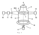
図3は、本発明による装置の第3の実施形態の概念図を示している。この実施形態では、X線源13(または他の高エネルギー放射線源)が、測定データをキャプチャするための画像装置10としてX線検出器7(または他の高エネルギー放射線検出器)と共に使用される。この実施形態もまた、光学的に不透明な容器及び/または液体に特に適している。
FIG. 3 shows a schematic diagram of a third embodiment of the device according to the invention. In this embodiment, an X-ray source 13 (or other high energy radiation source) is used together with an X-ray detector 7 (or other high energy radiation detector) as the
図4は、試験中の容器2の断面図を示しており、関心領域ROIは、容器2に含まれる液体3の表面4を包含している。最初は、関心領域ROIがわからない可能性があり、装置の操作者によって手動で、または例えば画像分析プロセッサ11の助けを借りて自動的に調整される必要がある。図4では、液体3が、容器2の回転によって容器2の壁9にどのように押し付けられるかがはっきりと見え、これにより、液体3の表面4が壁9でΔhの高さが増加した湾曲した形状を有する。また、容器2が左右に揺れる場合、(容器2の断面図に見られるように)2つの対向する壁9の間の液体3の表面4の顕著な高さの差Δhがあるだろう。
FIG. 4 shows a cross-sectional view of the
上記の例では、回転運動が容器2に誘導される。しかしながら、容器2は、例えば、容器を振動、振とう、ガタガタ揺らす、または、振り動かすなどの他の方法で容器2を攪拌するプレート/ディスク16上に配置/取り付けられ得、例えば、特定のアプリケーションでは並進運動を含む。
In the example above, a rotational movement is induced in the
図5は、関心領域のROIが長方形としてマークされた、試験中の容器2の断面図の写真を示している。見てわかるように、液体3の表面4は、攪拌による液体3の乱流表面上に反射するため、照明ユニット8(この場合は容器2の下方にある)からの光の反射により、写真では暗い領域として表示される。関心領域ROIは、例えば、グリッドによって複数のフィールドに分割され得、グリッドの各フィールド内の暗い(例えば、黒)ピクセルの数は、ピクセルカウンタを使用して判断され得る。続いて、事前定義された閾値を超える多数の暗いピクセルを含むそれらのフィールドの位置が決定され得、これに基づいて、表面4の形または形状に関する情報が確立される。この情報から、容器2が回転、振動、振とう、ガタガタ揺れる、または、揺り動かされている(例えば、動きの特定の状態または種類)のかを検出し得る。容器の動きの強さ、例えば容器の回転速度ですら判断することも可能である。さらに、一連の画像をキャプチャすることにより、動きの強さ、例えば回転速度が変化しているかどうか、つまり増加、減少、または安定しているかどうかを判断することが可能である。
FIG. 5 shows a photograph of a cross-sectional view of the
ピクセルカウンタを使用する本発明の特に単純な実施例では、特定の事前定義されたグレーレベル値を超える強度を有する関心領域全体内のピクセルの数は、ピクセルカウンタで判断される(例えば、「暗い」ピクセルを数える)。この数が事前定義された閾値を超える場合、液体3及び容器2は動いていると見なされる。ピクセルカウンタで決定される数が多いほど、液体3及び容器2の動きが強くなる。従って、動きの強さは、ピクセルカウンタで判断される暗いピクセルの数からも判断され得る。従って、時間の経過に伴うこの数の増加は、液体3及びその容器2の動きが強くなることを示し、時間の経過に伴うこの数の減少は、液体3及びその容器2の動きが弱くなることを示す。
In a particularly simple embodiment of the invention using a pixel counter, the number of pixels within the entire region of interest that have an intensity exceeding a certain predefined gray level value is determined by the pixel counter (e.g., "dark ” counting pixels). If this number exceeds a predefined threshold,
1 駆動機構
2 容器
3 液体
4 表面
5 光学センサ、カメラ
6 音響/音センサ
7 X線検出器
8 照明ユニット
9 容器壁
10 測定/画像装置
11 (画像解析)プロセッサ
12 音響/音源
13 X線源
14 モーション/回転インジケータ
15 レンズ
16 回転/可動プレート/ディスク
17 モーター
1
Claims (23)
- 前記容器(2)内の前記液体(3)の表面(4)の画像データをキャプチャするステップと;
- 前記画像データから、前記液体(3)の前記表面(4)の形状に関する形状データを抽出するステップと;
- 前記形状データに基づいて、前記容器(2)が動いているかどうかを検出するステップと;
を備えることを特徴とする方法。 A method for monitoring a drive mechanism (1) of an automatic inspection system for inducing movement in a container (2) partially filled with liquid (3), comprising:
- capturing image data of the surface (4) of the liquid (3) in the container (2);
- extracting from the image data shape data relating to the shape of the surface (4) of the liquid (3);
- based on the shape data, detecting whether the container (2) is in motion;
A method comprising:
- 光学センサ(5);
- 超音波センサまたはレーザーベースの音響センサ(6);
- X線検出器(7);
の手段のうちの1つによって実行されることを特徴とする請求項1に記載の方法。 The step of capturing the image data is:
- an optical sensor (5);
- ultrasonic sensors or laser-based acoustic sensors (6);
- an X-ray detector (7);
A method according to claim 1, characterized in that it is performed by one of the means of
- 前記容器(2)の下部照明、及び/または、上部照明、及び/または、背面照明、及び/または、側面照明、及び/または、前面照明、斜め下部照明、斜め上部照明、斜め背面照明または斜め前面照明を適用するステップ、
をさらに備えることを特徴とする請求項2に記載の方法。 When said step of capturing image data is performed by said optical sensor (5):
- bottom lighting and/or top lighting and/or back lighting and/or side lighting and/or front lighting, oblique bottom lighting, oblique top lighting, oblique back lighting or applying oblique front lighting;
3. The method of claim 2, further comprising:
- 前記液体(3)の前記表面(4)の少なくとも一部が配置されている前記容器(2)のセクションを含む関心領域(ROI)を判断するステップ、
を備えることを特徴とする請求項1~5のいずれか一項に記載の方法。 The capturing step includes:
- determining a region of interest (ROI) comprising a section of said container (2) in which at least part of said surface (4) of said liquid (3) is located;
A method according to any one of claims 1 to 5, characterized in that it comprises
- 前記表面(4)の曲率または傾斜を判断するステップ;
- 前記容器(2)の壁(9)での前記表面(4)の高さと、前記容器(2)の中央領域内での前記表面(4)の高さと、の差(Δh)を判断するステップ;
- 前記液体(3)内の渦(v)または乱流の存在を判断するステップ;
のうちの少なくとも1つを備えることを特徴とする請求項1~6のいずれか一項に記載の方法。 The step of extracting shape data includes :
- determining the curvature or slope of said surface (4);
- determining the difference (Δh) between the height of the surface (4) at the wall (9) of the container (2) and the height of the surface (4) within the central region of the container (2); step;
- determining the presence of eddies (v) or turbulence in said liquid (3);
A method according to any one of claims 1 to 6, characterized in that it comprises at least one of
- 前記表面(4)の形状が、事前定義された許容範囲内で事前定義されたテンプレートと一致するかどうかを判断するステップ;
- 曲率半径が事前定義された値を超えているかどうかを判断するステップ;
- 前記高さの差(Δh)が事前定義された値を超えているかどうかを判断するステップ;
のうちの少なくとも1つを備えることを特徴とする請求項7に記載の方法。 The detection steps are:
- determining whether the shape of said surface (4) matches a predefined template within a predefined tolerance;
- determining if the radius of curvature exceeds a predefined value;
- determining whether said height difference (Δh) exceeds a predefined value;
8. The method of claim 7, comprising at least one of:
- 前記形状データに基づいて前記容器(2)の動きの強さを判断するステップ、
を備えることを特徴とする請求項1~10のいずれか一項に記載の方法。 The step of determining
- determining the strength of movement of said container (2) on the basis of said shape data;
A method according to any one of claims 1 to 10, characterized in that it comprises
- 異なる時間に判断された前記形状データに基づいて、前記容器(2)の動きの強さの変化を判断するステップ、
を備えることを特徴とする請求項1~11のいずれか一項に記載の方法。 The capturing step and the extracting step are repeated multiple times, and the determining step comprises:
- determining changes in the intensity of movement of said container (2) based on said shape data determined at different times;
A method according to any one of claims 1 to 11, characterized in that it comprises
- 画像センサを備える画像装置(10)と;
- 前記画像装置(10)に動作可能に接続された画像分析プロセッサ(11)と;
を備え、
- 前記画像装置(10)は、前記容器(2)内の前記液体(3)の表面(4)の画像データをキャプチャするように適合されており、
- 前記画像分析プロセッサ(11)は、前記画像データから前記表面(4)の形状に関する形状データを抽出して、前記形状データに基づいて前記容器(2)が動いているかを検出するように適合されていることを特徴とする装置。 A device for monitoring a drive mechanism (1) of an automatic inspection system for inducing movement in a container (2) partially filled with liquid (3), comprising:
- an imaging device (10) comprising an image sensor;
- an image analysis processor (11) operatively connected to said imaging device (10);
with
- said imaging device (10) is adapted to capture image data of a surface (4) of said liquid (3) in said container (2);
- said image analysis processor (11) is adapted to extract shape data relating to the shape of said surface (4) from said image data and to detect if said container (2) is in motion based on said shape data; A device characterized by:
- 光学センサ(5)と、前記容器(2)の下部照明、上部照明、背面照明、側面照明、及び、前面照明のいずれかまたは任意の組み合わせを提供するように適合された照明ユニット(8);
- 超音波源(12)と、超音波トランスデューサーまたはレーザーベースの音響センサ(6);並びに、
- X線源(13)とX線検出器(7);
のうちの少なくとも1つを備えることを特徴とする請求項15または16に記載の装置。 Said imaging device (10):
- an optical sensor (5) and lighting adapted to provide any or any combination of bottom lighting , top lighting , back lighting , side lighting and front lighting of said container (2); unit (8);
- an ultrasound source (12) and an ultrasound transducer or laser-based acoustic sensor (6);
- an X-ray source (13) and an X-ray detector (7);
17. Apparatus according to claim 15 or 16, characterized in that it comprises at least one of:
Applications Claiming Priority (3)
| Application Number | Priority Date | Filing Date | Title |
|---|---|---|---|
| CH00737/18 | 2018-06-07 | ||
| CH7372018 | 2018-06-07 | ||
| PCT/EP2019/064746 WO2019234138A1 (en) | 2018-06-07 | 2019-06-06 | Method and apparatus for monitoring a drive mechanism of an automated inspection system for inducing motion to a container partially filled with a liquid |
Publications (2)
| Publication Number | Publication Date |
|---|---|
| JP2021525884A JP2021525884A (en) | 2021-09-27 |
| JP7330213B2 true JP7330213B2 (en) | 2023-08-21 |
Family
ID=66810806
Family Applications (1)
| Application Number | Title | Priority Date | Filing Date |
|---|---|---|---|
| JP2020567802A Active JP7330213B2 (en) | 2018-06-07 | 2019-06-06 | Method and Apparatus for Monitoring the Drive Mechanism of an Automated Inspection System for Inducing Motion in a Partially Liquid Filled Container |
Country Status (8)
| Country | Link |
|---|---|
| US (1) | US20210245121A1 (en) |
| EP (1) | EP3801861B1 (en) |
| JP (1) | JP7330213B2 (en) |
| KR (1) | KR102659641B1 (en) |
| CN (1) | CN112203756A (en) |
| CA (1) | CA3100117A1 (en) |
| DK (1) | DK3801861T3 (en) |
| WO (1) | WO2019234138A1 (en) |
Families Citing this family (6)
| Publication number | Priority date | Publication date | Assignee | Title |
|---|---|---|---|---|
| CN113936376A (en) * | 2021-09-07 | 2022-01-14 | 陶朗环保技术(厦门)有限公司 | Beverage bottle recovery machine and beverage bottle movement monitoring method |
| WO2023105724A1 (en) * | 2021-12-09 | 2023-06-15 | 日本電気株式会社 | Foreign matter inspecting device |
| JP7845867B2 (en) * | 2022-01-26 | 2026-04-14 | 本田技研工業株式会社 | Apparatus and method for manufacturing battery slurry |
| CN116550195A (en) * | 2022-01-28 | 2023-08-08 | 深圳晶泰科技有限公司 | Oscillating device and experimental equipment |
| CN114570248B (en) * | 2022-03-14 | 2023-02-24 | 河南省肿瘤医院 | Vein medicine configuration detecting system based on deep learning |
| KR102858226B1 (en) * | 2022-09-01 | 2025-09-11 | 중앙대학교 산학협력단 | Anti-spilling system for liquid delivery robot |
Citations (4)
| Publication number | Priority date | Publication date | Assignee | Title |
|---|---|---|---|---|
| US20050248765A1 (en) | 2004-03-09 | 2005-11-10 | Budd Gerald W | Small container fluid dynamics to produce optimized inspection conditions |
| JP2009014705A (en) | 2007-06-29 | 2009-01-22 | Qinghua Univ | Method and apparatus for inspecting drugs hidden in liquid articles |
| JP2016080609A (en) | 2014-10-21 | 2016-05-16 | 日立Geニュークリア・エナジー株式会社 | Ultrasonic leak detection device and leak detection method using the same |
| JP2017201335A (en) | 2011-08-29 | 2017-11-09 | アムジェン インコーポレイテッド | Methods and apparatus for nondestructive detection of undissolved particles in fluid |
Family Cites Families (19)
| Publication number | Priority date | Publication date | Assignee | Title |
|---|---|---|---|---|
| US3966332A (en) * | 1974-09-12 | 1976-06-29 | Schering Corporation | Method and apparatus for inspecting liquids in transparent containers |
| IT1048490B (en) * | 1974-09-12 | 1980-11-20 | Scherico Ltd | METHOD AND APPARATUS TO CONTROL LIQUIDS WITHIN TRANSPARENT CONTAINERS |
| GB1524042A (en) * | 1975-08-19 | 1978-09-06 | Scherico Ltd | Method and apparatus for inspecting liquids in transparent containers |
| DE19860901A1 (en) * | 1998-12-30 | 2000-07-06 | Bosch Gmbh Robert | Device for determining situation and/or movement of surface of liquid situated in container in vehicle has A/D converter, processor, and memory to calculate rotation of liquid surface determined from recorded distance values |
| US6782122B1 (en) * | 2000-04-27 | 2004-08-24 | Simmonds Precision Products, Inc. | Apparatus for measuring height of a liquid in a container using area image pattern recognition techniques |
| EP1235059A1 (en) * | 2001-02-14 | 2002-08-28 | Endress + Hauser GmbH + Co. KG | Microwave level detector |
| JP4743816B2 (en) * | 2001-09-21 | 2011-08-10 | キリンテクノシステム株式会社 | Container inspection device |
| JP2005017004A (en) * | 2003-06-24 | 2005-01-20 | Sukiyan Technol:Kk | System for inspecting foreign matter in glass bottle |
| US7310143B2 (en) * | 2003-11-09 | 2007-12-18 | Gerald Walter Budd | NIST traceable automated visual inspection system for an inspection of particles in solution |
| EP1630550A1 (en) * | 2004-08-27 | 2006-03-01 | Moller & Devicon A/S | Methods and apparatuses of detecting foreign particles or faults in a plurality of filled containers |
| US20070115467A1 (en) * | 2005-11-23 | 2007-05-24 | Owens-Brockway Glass Container | Apparatus and method for ensuring rotation of a container during inspection |
| CN101573618A (en) * | 2006-09-15 | 2009-11-04 | 赫摩耐提克斯公司 | Surface mapping by optical manipulation of particles in relation to a functionalized surface |
| US8774487B2 (en) * | 2010-02-17 | 2014-07-08 | Joshua D. Levine | Method and apparatus for remotely performing hematologic analysis utilizing a transmitted image of a centrifuged analysis tube |
| CN103025859A (en) * | 2010-05-25 | 2013-04-03 | 阿尔利克斯公司 | Methods and apparatuses for detection of positional freedom of particles in biological and chemical analyses and applications in immunodiagnostics |
| DE102010053771A1 (en) * | 2010-12-08 | 2012-06-14 | Khs Gmbh | Inspection device for foreign matter inspection |
| GB201103642D0 (en) * | 2011-03-03 | 2011-04-13 | Univ Bradford | Methods and systems for detection of liquid surface fluctuations |
| EP3252476B1 (en) * | 2015-01-28 | 2024-10-30 | Hitachi High-Tech Corporation | Liquid surface inspection device, automated analysis device, and processing device |
| DE202015001463U1 (en) * | 2015-02-25 | 2016-05-30 | Seidenader Maschinenbau Gmbh | rotation monitoring |
| CN106896122B (en) * | 2015-12-18 | 2019-07-30 | 清华大学 | Liquid detection method and system |
-
2019
- 2019-06-06 JP JP2020567802A patent/JP7330213B2/en active Active
- 2019-06-06 WO PCT/EP2019/064746 patent/WO2019234138A1/en not_active Ceased
- 2019-06-06 DK DK19729514.0T patent/DK3801861T3/en active
- 2019-06-06 US US16/972,910 patent/US20210245121A1/en active Pending
- 2019-06-06 CN CN201980038154.0A patent/CN112203756A/en active Pending
- 2019-06-06 KR KR1020207033425A patent/KR102659641B1/en active Active
- 2019-06-06 CA CA3100117A patent/CA3100117A1/en active Pending
- 2019-06-06 EP EP19729514.0A patent/EP3801861B1/en active Active
Patent Citations (4)
| Publication number | Priority date | Publication date | Assignee | Title |
|---|---|---|---|---|
| US20050248765A1 (en) | 2004-03-09 | 2005-11-10 | Budd Gerald W | Small container fluid dynamics to produce optimized inspection conditions |
| JP2009014705A (en) | 2007-06-29 | 2009-01-22 | Qinghua Univ | Method and apparatus for inspecting drugs hidden in liquid articles |
| JP2017201335A (en) | 2011-08-29 | 2017-11-09 | アムジェン インコーポレイテッド | Methods and apparatus for nondestructive detection of undissolved particles in fluid |
| JP2016080609A (en) | 2014-10-21 | 2016-05-16 | 日立Geニュークリア・エナジー株式会社 | Ultrasonic leak detection device and leak detection method using the same |
Also Published As
| Publication number | Publication date |
|---|---|
| KR20210018804A (en) | 2021-02-18 |
| KR102659641B1 (en) | 2024-04-22 |
| WO2019234138A1 (en) | 2019-12-12 |
| EP3801861B1 (en) | 2025-09-17 |
| CA3100117A1 (en) | 2019-12-12 |
| EP3801861A1 (en) | 2021-04-14 |
| US20210245121A1 (en) | 2021-08-12 |
| JP2021525884A (en) | 2021-09-27 |
| DK3801861T3 (en) | 2025-12-15 |
| CN112203756A (en) | 2021-01-08 |
Similar Documents
| Publication | Publication Date | Title |
|---|---|---|
| JP7330213B2 (en) | Method and Apparatus for Monitoring the Drive Mechanism of an Automated Inspection System for Inducing Motion in a Partially Liquid Filled Container | |
| JP7216146B2 (en) | Method and apparatus for nondestructive detection of undissolved particles in fluids | |
| JP7797568B2 (en) | Sheet illumination for particle detection in pharmaceutical containers | |
| JP3193377B2 (en) | Method and apparatus for inspecting liquid-filled containers | |
| JP5918508B2 (en) | Apparatus and method for detecting solids in liquid phase | |
| JP6333584B2 (en) | Clinical laboratory equipment | |
| JP2012112938A5 (en) | ||
| JP5508106B2 (en) | Foreign matter detection method, foreign matter detection device and foreign matter detection program in fluid | |
| JP7470587B2 (en) | Specimen characteristic determination device and specimen characteristic determination method | |
| JP2007309889A (en) | Foreign matter detector and foreign matter detecting method | |
| JP2002257707A (en) | Image analysis cell | |
| JPH08254505A (en) | Detection method of minute flaw in transparent object | |
| KR102232502B1 (en) | Photothermal reagent measurement apparatus with agitator | |
| US3874800A (en) | Apparatus for detecting liquid pollution in a transparent container | |
| KR102697656B1 (en) | Optical Apparatus and method for detecting foreign substances mixed in solution | |
| JP7238964B2 (en) | Inspection device, inspection method, and program | |
| CN108254379A (en) | A kind of defect detecting device and method | |
| JP2026013493A (en) | Aggregate detection device and aggregate detection method | |
| JPH04130254A (en) | Method and apparatus for detecting bubble in liquid sealed container | |
| CN103323961A (en) | Detection device and method for electric energy meter liquid crystal display | |
| JPS63229348A (en) | Method for detecting small-size foreign matter in container | |
| APRAHAMIAN et al. | Nondestructive testing using TRW acousto-optical imaging system(Evaluating applicability of acousto-optical imaging for nondestructive testing)[Interim Report, 1 Jul. 1971- 1 Jan. 1972] |
Legal Events
| Date | Code | Title | Description |
|---|---|---|---|
| A621 | Written request for application examination |
Free format text: JAPANESE INTERMEDIATE CODE: A621 Effective date: 20220525 |
|
| A977 | Report on retrieval |
Free format text: JAPANESE INTERMEDIATE CODE: A971007 Effective date: 20230118 |
|
| A131 | Notification of reasons for refusal |
Free format text: JAPANESE INTERMEDIATE CODE: A131 Effective date: 20230123 |
|
| A521 | Request for written amendment filed |
Free format text: JAPANESE INTERMEDIATE CODE: A523 Effective date: 20230413 |
|
| A131 | Notification of reasons for refusal |
Free format text: JAPANESE INTERMEDIATE CODE: A131 Effective date: 20230605 |
|
| A521 | Request for written amendment filed |
Free format text: JAPANESE INTERMEDIATE CODE: A523 Effective date: 20230622 |
|
| TRDD | Decision of grant or rejection written | ||
| A01 | Written decision to grant a patent or to grant a registration (utility model) |
Free format text: JAPANESE INTERMEDIATE CODE: A01 Effective date: 20230710 |
|
| A61 | First payment of annual fees (during grant procedure) |
Free format text: JAPANESE INTERMEDIATE CODE: A61 Effective date: 20230808 |
|
| R150 | Certificate of patent or registration of utility model |
Ref document number: 7330213 Country of ref document: JP Free format text: JAPANESE INTERMEDIATE CODE: R150 |