JP7308744B2 - Method and apparatus for measuring absorbance of substance in solution - Google Patents
Method and apparatus for measuring absorbance of substance in solution Download PDFInfo
- Publication number
- JP7308744B2 JP7308744B2 JP2019500830A JP2019500830A JP7308744B2 JP 7308744 B2 JP7308744 B2 JP 7308744B2 JP 2019500830 A JP2019500830 A JP 2019500830A JP 2019500830 A JP2019500830 A JP 2019500830A JP 7308744 B2 JP7308744 B2 JP 7308744B2
- Authority
- JP
- Japan
- Prior art keywords
- signal
- reference beam
- detector
- modulating
- measuring
- Prior art date
- Legal status (The legal status is an assumption and is not a legal conclusion. Google has not performed a legal analysis and makes no representation as to the accuracy of the status listed.)
- Active
Links
Images


Classifications
-
- G—PHYSICS
- G01—MEASURING; TESTING
- G01N—INVESTIGATING OR ANALYSING MATERIALS BY DETERMINING THEIR CHEMICAL OR PHYSICAL PROPERTIES
- G01N21/00—Investigating or analysing materials by the use of optical means, i.e. using sub-millimetre waves, infrared, visible or ultraviolet light
- G01N21/17—Systems in which incident light is modified in accordance with the properties of the material investigated
- G01N21/25—Colour; Spectral properties, i.e. comparison of effect of material on the light at two or more different wavelengths or wavelength bands
- G01N21/31—Investigating relative effect of material at wavelengths characteristic of specific elements or molecules, e.g. atomic absorption spectrometry
- G01N21/33—Investigating relative effect of material at wavelengths characteristic of specific elements or molecules, e.g. atomic absorption spectrometry using ultraviolet light
-
- G—PHYSICS
- G01—MEASURING; TESTING
- G01N—INVESTIGATING OR ANALYSING MATERIALS BY DETERMINING THEIR CHEMICAL OR PHYSICAL PROPERTIES
- G01N21/00—Investigating or analysing materials by the use of optical means, i.e. using sub-millimetre waves, infrared, visible or ultraviolet light
- G01N21/01—Arrangements or apparatus for facilitating the optical investigation
- G01N21/03—Cuvette constructions
- G01N21/05—Flow-through cuvettes
-
- G—PHYSICS
- G01—MEASURING; TESTING
- G01N—INVESTIGATING OR ANALYSING MATERIALS BY DETERMINING THEIR CHEMICAL OR PHYSICAL PROPERTIES
- G01N21/00—Investigating or analysing materials by the use of optical means, i.e. using sub-millimetre waves, infrared, visible or ultraviolet light
- G01N21/84—Systems specially adapted for particular applications
- G01N21/85—Investigating moving fluids or granular solids
- G01N21/8507—Probe photometers, i.e. with optical measuring part dipped into fluid sample
-
- G—PHYSICS
- G01—MEASURING; TESTING
- G01N—INVESTIGATING OR ANALYSING MATERIALS BY DETERMINING THEIR CHEMICAL OR PHYSICAL PROPERTIES
- G01N30/00—Investigating or analysing materials by separation into components using adsorption, absorption or similar phenomena or using ion-exchange, e.g. chromatography or field flow fractionation
- G01N30/02—Column chromatography
- G01N30/62—Detectors specially adapted therefor
- G01N30/74—Optical detectors
-
- G—PHYSICS
- G01—MEASURING; TESTING
- G01N—INVESTIGATING OR ANALYSING MATERIALS BY DETERMINING THEIR CHEMICAL OR PHYSICAL PROPERTIES
- G01N21/00—Investigating or analysing materials by the use of optical means, i.e. using sub-millimetre waves, infrared, visible or ultraviolet light
- G01N21/17—Systems in which incident light is modified in accordance with the properties of the material investigated
- G01N21/25—Colour; Spectral properties, i.e. comparison of effect of material on the light at two or more different wavelengths or wavelength bands
- G01N21/31—Investigating relative effect of material at wavelengths characteristic of specific elements or molecules, e.g. atomic absorption spectrometry
- G01N2021/3125—Measuring the absorption by excited molecules
-
- G—PHYSICS
- G01—MEASURING; TESTING
- G01N—INVESTIGATING OR ANALYSING MATERIALS BY DETERMINING THEIR CHEMICAL OR PHYSICAL PROPERTIES
- G01N30/00—Investigating or analysing materials by separation into components using adsorption, absorption or similar phenomena or using ion-exchange, e.g. chromatography or field flow fractionation
- G01N30/02—Column chromatography
- G01N2030/022—Column chromatography characterised by the kind of separation mechanism
- G01N2030/027—Liquid chromatography
-
- G—PHYSICS
- G01—MEASURING; TESTING
- G01N—INVESTIGATING OR ANALYSING MATERIALS BY DETERMINING THEIR CHEMICAL OR PHYSICAL PROPERTIES
- G01N2201/00—Features of devices classified in G01N21/00
- G01N2201/06—Illumination; Optics
- G01N2201/062—LED's
- G01N2201/0624—Compensating variation in output of LED source
-
- G—PHYSICS
- G01—MEASURING; TESTING
- G01N—INVESTIGATING OR ANALYSING MATERIALS BY DETERMINING THEIR CHEMICAL OR PHYSICAL PROPERTIES
- G01N2201/00—Features of devices classified in G01N21/00
- G01N2201/06—Illumination; Optics
- G01N2201/062—LED's
- G01N2201/0625—Modulated LED
-
- G—PHYSICS
- G01—MEASURING; TESTING
- G01N—INVESTIGATING OR ANALYSING MATERIALS BY DETERMINING THEIR CHEMICAL OR PHYSICAL PROPERTIES
- G01N2201/00—Features of devices classified in G01N21/00
- G01N2201/06—Illumination; Optics
- G01N2201/069—Supply of sources
- G01N2201/0691—Modulated (not pulsed supply)
-
- G—PHYSICS
- G01—MEASURING; TESTING
- G01N—INVESTIGATING OR ANALYSING MATERIALS BY DETERMINING THEIR CHEMICAL OR PHYSICAL PROPERTIES
- G01N2201/00—Features of devices classified in G01N21/00
- G01N2201/12—Circuits of general importance; Signal processing
- G01N2201/127—Calibration; base line adjustment; drift compensation
Landscapes
- Physics & Mathematics (AREA)
- Biochemistry (AREA)
- Health & Medical Sciences (AREA)
- Life Sciences & Earth Sciences (AREA)
- Chemical & Material Sciences (AREA)
- Analytical Chemistry (AREA)
- General Health & Medical Sciences (AREA)
- General Physics & Mathematics (AREA)
- Immunology (AREA)
- Pathology (AREA)
- Spectroscopy & Molecular Physics (AREA)
- Investigating Or Analysing Materials By Optical Means (AREA)
- Spectrometry And Color Measurement (AREA)
Description
本発明は、溶液中の物質の吸光度を測定するための方法および測定装置に関する。 The present invention relates to a method and measuring device for measuring the absorbance of substances in solution.
多くの物質は、その化学組成のために紫外線または可視光線を吸収している。物質による光線の吸収は、かかる物質の存在を検出し、その濃度を測定するための基準として、長年にわたり使用されてきた。物質の濃度は、ランベルト・ベールの法則(Beer Lambert Law)を用いて、以下のように求めることができる。 Many substances absorb ultraviolet or visible light because of their chemical composition. The absorption of light by substances has been used for many years as a criterion for detecting the presence of such substances and for determining their concentrations. The concentration of a substance can be obtained as follows using the Beer Lambert Law.
A=Ebcここで、
Aは吸光度であり、
EはL mol-1cm-1を単位とするモル吸光係数であり、
bはcmで定義されるサンプルの光路長であり、
cは溶液中の化合物の濃度であり、mol-1で表される。
A=Ebc where
A is the absorbance,
E is the molar extinction coefficient in units of L mol −1 cm −1 ;
b is the optical path length of the sample defined in cm;
c is the concentration of the compound in solution, expressed in mol −1 .
UV領域は、約10nm~400nmの波長光からなるとみなすことができ、180nm~300nmの波長光は「深UV」として知られている。深紫外線(UV)領域で吸光する物質を検出する分析機器のほとんどは、光源として水銀ランプ、重水素ランプまたはキセノンフラッシュランプを使用している。かかる機器の1つの例がフローセルであり、ここでは1または複数のUV吸収物質を含む溶液が、UV光源(たとえば、水銀ランプ)とUV検出器(たとえば、光電子増倍管、光ダイオードまたは光トランジスタ)との間に配置され、検出器に到達する紫外線の強度の変化が、溶液中のUV吸収物質の濃度と関連している。 The UV region can be considered to consist of wavelengths of light between about 10 nm and 400 nm, with wavelengths between 180 nm and 300 nm being known as "deep UV". Most analytical instruments that detect substances that absorb in the deep ultraviolet (UV) region use mercury lamps, deuterium lamps or xenon flash lamps as light sources. One example of such an instrument is a flow cell, in which a solution containing one or more UV absorbing substances is combined with a UV light source (e.g. mercury lamp) and a UV detector (e.g. photomultiplier tube, photodiode or phototransistor). ) and the change in the intensity of the UV light reaching the detector is related to the concentration of the UV-absorbing substance in solution.
タンパク質、核酸、およびペプチドの検出は、環境科学、生物科学、および化学を含む多くの分野において非常に重要となっている。タンパク質は深UV領域において主に2つの吸光ピークを有し、1つはペプチド結合が吸光する最大約190nmの、強度が非常に高い吸光帯であり、もう1つのピークは、芳香族アミノ酸(たとえば、チロシン、トリプトファン、およびフェニルアラニン)による吸光に起因して、約280nmと強度が低くなっている。 The detection of proteins, nucleic acids, and peptides has become of great importance in many fields, including environmental sciences, biological sciences, and chemistry. Proteins have mainly two absorption peaks in the deep UV region, one is a very intense absorption band up to about 190 nm where peptide bonds absorb, and the other peak is for aromatic amino acids (e.g. , tyrosine, tryptophan, and phenylalanine), resulting in a lower intensity at about 280 nm.
国際公開第2007/062800号パンフレットおよび国際公開第2013/178770号パンフレットには、液体サンプル中の物質の濃度を分析するための光源として、紫外線LED(UV LED)を使用することについて記載されている。 WO2007/062800 and WO2013/178770 describe the use of ultraviolet LEDs (UV LEDs) as light sources for analyzing the concentration of substances in liquid samples. .
UV LEDから測定装置への入射光は、検出器に直接供給される参照光線と、サンプルを通過してから検出器に供給される信号光線とに分割される。検出した信号光線は大幅に増幅され、かつ検出した参照光線を増幅したバージョンと比較される。この種の装置にはドリフトに関連する問題が生じる可能性があり、これはなぜなら、検出器の増幅度が高いということは、たとえば温度変化または湿度変化に起因して、チャネル内にわずかに不均等な何らかの性能変化が生じると、測定された吸光信号にドリフトが発生することを意味するからである。流動性サンプル中の経時的な吸光度変化を測定する装置は、静的サンプルに対して短期測定を行う装置と比較して、当然ながら装置内のドリフトに対してはるかに敏感になる。 Incident light from the UV LED to the measurement device is split into a reference beam that is delivered directly to the detector and a signal beam that passes through the sample and is delivered to the detector. The detected signal beam is greatly amplified and compared to an amplified version of the detected reference beam. Drift-related problems can arise in this type of device, because the high amplification of the detector can result in small disturbances in the channel, e.g. due to temperature or humidity changes. This is because any equivalent performance change would imply drift in the measured absorbance signal. Devices that measure absorbance changes over time in flowable samples are naturally much more sensitive to drift in the device than devices that make short-term measurements on static samples.
本発明の目的は、測定セル内溶液中の物質の吸光度を測定するための、改良された方法および測定装置を提供することである。 SUMMARY OF THE INVENTION It is an object of the present invention to provide an improved method and apparatus for measuring the absorbance of substances in solutions within a measuring cell.
本発明のさらに別の目的は、測定セル内溶液中の物質の吸光度を測定するための、強健かつ信頼性の高い方法および測定装置を提供することである。 Yet another object of the present invention is to provide a robust and reliable method and measurement device for measuring the absorbance of substances in solutions in measuring cells.
これは、独立請求項による方法および測定装置において達成される。 This is achieved in the method and measuring device according to the independent claims.
ここでは、1つの検出器のみを使用して参照光線と信号光線との両方を同時に測定しているが、これは、2つの別個の検出器を使用することによって発生し得るいかなるドリフトも排除されることを意味する。 Here, only one detector is used to simultaneously measure both the reference and signal beams, which eliminates any drift that can occur with the use of two separate detectors. means that
本発明によれば、測定セル内溶液中の物質の吸光度を測定するための方法であって、前記方法は、
-光源からの第1の光線をビームスプリッタに向けて伝送するステップと、
-前記ビームスプリッタによって、前記第1の光線を信号光線および参照光線に分割するステップと、
-前記信号光線を変調するステップと、
-前記参照光線を変調するステップと、
-前記信号光線が前記測定セルを通過するように、前記測定セルを設けるステップと、
-検出器で信号を検出するステップであって、前記信号は、前記検出器によって検出された前記信号光線および前記参照光線の合成信号強度である、ステップと、
-前記検出器によって検出された合成信号から、前記信号光線および前記参照光線の強度を再現するために、前記検出信号の同期検波を行うステップであって、前記同期検波は、前記信号光線および前記参照光線に対して行われた前記変調に基づいている、ステップと
を含む、方法を提供する。
According to the present invention, a method for measuring the absorbance of a substance in a solution in a measuring cell, said method comprising:
- transmitting a first ray from a light source towards a beam splitter;
- splitting the first beam into a signal beam and a reference beam by means of the beam splitter;
- modulating said signal beam;
- modulating said reference beam;
- providing said measuring cell such that said signal beam passes through said measuring cell;
- detecting a signal with a detector, said signal being the combined signal intensity of said signal beam and said reference beam detected by said detector;
- from the combined signal detected by the detector, synchronous detection of the detected signal in order to reconstruct the intensities of the signal beam and the reference beam, the synchronous detection comprising the signal beam and the is based on said modulation performed on a reference beam, comprising the steps of:
また、本発明によれば、内部の測定セル内溶液中の物質の吸光度を測定するための測定装置であって、前記測定装置は、
-第1の光線を伝送する光源と、
-前記第1の光線が、自身によって信号光線および参照光線に分割されるように設けられたビームスプリッタと、
-前記信号光線が、自身を通過するように配置された前記測定セルと、
-前記信号光線を変調するように構成された第1の信号変調装置と、
-前記参照光線を変調するように構成された第2の信号変調装置と、
-前記信号光線が変調されて前記測定セルを通過したときに、前記信号光線を検出し、また前記参照光線が変調されたときに、前記参照光線も検出するように構成された検出器であって、前記検出器は、前記検出器によって検出された合成信号から、前記信号光線および前記参照光線の強度を再現するために、前記検出信号の同期検波を行うように構成された処理装置を備えるか、またはこれに接続されており、前記同期検波は、前記信号光線および前記参照光線に対して行われた前記変調に基づいている、検出器と
を備える、測定装置を提供する。
Further, according to the present invention, there is provided a measuring device for measuring the absorbance of a substance in a solution in an internal measuring cell, the measuring device comprising:
- a light source that transmits the first light beam;
- a beam splitter provided by itself to split said first beam into a signal beam and a reference beam;
- the measuring cell arranged such that the signal beam passes through it;
- a first signal modulator arranged to modulate said signal beam;
- a second signal modulator arranged to modulate said reference beam;
- a detector adapted to detect said signal beam when said signal beam has been modulated and passed through said measuring cell, and also to detect said reference beam when said reference beam has been modulated; and said detector comprises a processing unit configured to perform coherent detection of said detected signal in order to reconstruct the intensities of said signal beam and said reference beam from a combined signal detected by said detector. a detector connected to or connected to said signal beam and said synchronous detection being based on said modulation performed on said signal beam and said reference beam.
前記信号光線と前記参照光線とを、同じ検出器で同時に検出することができる。 The signal beam and the reference beam can be detected simultaneously with the same detector.
これは、前記信号を変調することから可能であり、ここでは流動性サンプル中の経時的な吸光度変化を測定することができる。 This is possible from modulating the signal, where the change in absorbance over time in a flowable sample can be measured.
本発明の一実施形態では、前記信号光線を変調するステップは、前記信号光線を第1の周波数で変調するステップを含み、前記参照光線を変調するステップは、前記第1の周波数とは異なる第2の周波数で前記参照光線を変調するステップを含む。これにより、2つの信号を検出器内で区別することができる。 In one embodiment of the invention, modulating the signal beam comprises modulating the signal beam at a first frequency, and modulating the reference beam comprises modulating a second frequency different from the first frequency. modulating the reference beam at two frequencies. This allows the two signals to be distinguished in the detector.
本発明の一実施形態では、前記信号光線と前記参照光線とを変調するステップは、前記信号光線および前記参照光線の両方に、正弦波変調または矩形波変調を施すステップを含む。 In one embodiment of the invention, modulating the signal beam and the reference beam comprises subjecting both the signal beam and the reference beam to sinusoidal or square wave modulation.
本発明の一実施形態では、前記測定セルはフローセルである。 In one embodiment of the invention, said measuring cell is a flow cell.
本発明の一実施形態では、本方法は、前記信号光線および前記参照光線の両方を同じ検出器によって検出できるように、少なくとも1つの光線方向転換装置を使用して、前記信号光線および前記参照光線の一方または両方の方向を転換させるステップをさらに含む。 In one embodiment of the invention, the method comprises using at least one beam redirecting device to detect said signal beam and said reference beam so that both said signal beam and said reference beam can be detected by the same detector. and reversing the direction of one or both of the .
本発明の一実施形態では、前記信号光線または前記参照光線の一方を変調するステップは、光源を制御するステップを含む。 In one embodiment of the invention, modulating one of the signal beam or the reference beam comprises controlling a light source.
本発明の一実施形態では、前記測定装置は、前記参照光線および前記信号光線を同じ検出器によって検出できるように、前記参照光線または前記信号光線の方向を転換させるように構成された、少なくとも1つの光線方向転換装置をさらに備える。 In an embodiment of the invention, said measuring device comprises at least one detector adapted to redirect said reference beam or said signal beam such that said reference beam and said signal beam can be detected by the same detector. It further comprises two beam redirecting devices.
本発明の一実施形態では、前記第1の信号変調装置および前記第2の信号変調装置は、異なる周波数で信号を変調するように構成されている。 In an embodiment of the invention, said first signal modulating device and said second signal modulating device are arranged to modulate signals at different frequencies.
本発明の一実施形態では、前記第1の信号変調装置は、前記信号光線の光路のいずれかに設けられるチョッパ、シャッタ、可動ミラー、音叉、または調整可能な灰色フィルタである。 In one embodiment of the invention, the first signal modulator is a chopper, shutter, movable mirror, tuning fork, or adjustable gray filter provided in any of the optical paths of the signal beam.
本発明の一実施形態では、前記第2の信号変調装置は、前記参照光線の光路のいずれかに設けられるチョッパ、シャッタ、可動ミラー、音叉、または調整可能な灰色フィルタである。 In one embodiment of the invention, said second signal modulator is a chopper, shutter, movable mirror, tuning fork or adjustable gray filter provided in any of the optical paths of said reference beam.
本発明の一実施形態では、前記第1または第2の信号変調装置のうちの一方は、光源を制御する装置である。 In one embodiment of the invention, one of said first or second signal modulating devices is a device for controlling a light source.
本発明の一実施形態では、前記ビームスプリッタは、前記第1の光線を信号光線および参照光線に分割する非対称ビームスプリッタであり、前記第1の光線の大部分を、前記参照光線よりも前記信号光線に指向させている。 In an embodiment of the invention, said beam splitter is an asymmetric beam splitter for splitting said first beam into a signal beam and a reference beam, wherein a greater proportion of said first beam is directed to said signal beam than said reference beam. Aiming for light rays.
図1は、測定セル3内に供給された溶液中の物質の吸光度を測定するための、従来技術の測定装置1を概略的に示した図である。測定装置1は、第1の光線7を伝送する光源5を備える。本測定装置は、第1の光線7が、自身によって信号光線11および参照光線13に分割されるように、本測定装置内に設けられたビームスプリッタ9をさらに備える。測定装置1は、信号光線11が、自身に供給された溶液を通過するように配置された測定セル3をさらに備える。測定装置1は、信号光線11が測定セル3を通過したときに、前記信号光線11を検出するように構成された第1の検出器15と、参照光線13を検出するように構成された第2の検出器17とをさらに備える。検出した基準値および信号値から、サンプルの吸光度を式A=log10(基準値/信号値)によって計算することができる。上述したように、この種の装置で、とりわけ液体クロマトグラフィーのように長く連続的な測定を行う場合には、ドリフトが問題となる。たとえばわずかな温度変化は、2つの異なる検出器のチャネルに不均等に影響を及ぼし、これによってドリフトおよび不正確な測定をもたらす可能性がある。
FIG. 1 shows schematically a prior art measuring
図2aは、本発明の一実施形態による測定装置21を概略的に示した図である。測定装置21は、前記測定装置の測定セル23内に供給された、溶液中の物質の吸光度を測定するように構成されている。測定装置21は、第1の光線27を伝送する光源25を備える。前記光源を、たとえばLEDまたは他の任意の種類の適切なランプとすることができる。本測定装置は、第1の光線27が、自身によって信号光線31および参照光線33に分割されるように設けられたビームスプリッタ29をさらに備える。ビームスプリッタ29を、たとえば半透鏡、または2つの光ファイバを並べて配置したものとすることができる。測定装置21は、信号光線31が、自身に供給された溶液を通過するように配置された測定セル23をさらに備える。測定セル23を、測定されるサンプルを含む静的測定セルとすることができるが、連続測定中にサンプルが流れるフローセルとすることもできる。
Figure 2a is a schematic illustration of a measuring
測定装置21は、信号光線31を変調するように構成された第1の信号変調装置35と、参照光線33を変調するように構成された第2の信号変調装置37とをさらに備える。本実施形態では、第1の信号変調装置35をビームスプリッタ29と測定セル23との間に配置している。しかしながら、これをまた、測定セル23の後方であるが、測定装置21内に設けられた検出器39の前方に配置することもできる。本発明によれば、検出器39は、信号光線31が変調されて測定セル23を通過したときに、前記信号光線31を検出し、また参照光線33が変調されたときに、前記参照光線33を検出するように構成されている。ここに示す実施形態では、検出器39は、それ以上方向転換することなく、信号光線31が自身によって検出されるように設けられている。本実施形態では、代わりに参照光線33を光線方向転換装置41によって方向転換させており、これによって光線方向転換装置41による方向転換と、第2の信号変調装置37による変調とを経た後に、検出器39によって参照光線33が検出されるようにしている。前記光線方向転換装置を鏡とすることができる。
The measuring
ここでは、第2の信号変調装置37を光線方向転換装置41の後方に設けてあるように示しているが、これをビームスプリッタ29と光線方向転換装置41との間に設けることも可能である。当然ながら、代わりに光線方向転換装置41を信号光線の経路内に設けることができ、検出器39を参照光線の経路内、すなわちビームスプリッタ29の直接後方に、参照光線33の方向に設けることもできる。適切な方法で、信号光線と参照光線とを同じ検出器に指向させるために、複数の光線方向転換装置を本測定装置に設けることもできる。光線方向転換装置を全く必要としない別の代替例としては、光源からのわずかに異なる2つの光線を、これら両方を受光するのに十分な大きさを有する検出器に入射させるか、または光ファイバに光線を誘導する例が挙げられる。光ファイバによる代替例を図2bに示している。以下の詳細な説明を参照されたい。
Although the
本発明による測定装置では、信号光線31および参照光線33の両方を同じ検出器39によって検出している。検出器39は、前記検出器39によって検出された合成信号から、信号光線31および参照光線33の強度を再現するために、前記検出信号の同期検波を行うように構成された処理装置43を備えるか、またはこれに接続されている。これは、検出器信号に変調信号をそれぞれ乗算し、次いでその結果をローパスフィルタリングすることによって達成される。このようにして、2つの異なる信号を再現し、これらから吸光度を計算することができる。処理装置43を完全にハードウェアから作製するか、完全にソフトウェアから作製するか、またはその2つの組み合わせとすることができる。本測定装置では、信号光線31と参照光線33とを同じ検出器39によって同時に検出することができる。
In the measuring device according to the invention both the
検出器39は、通常光ダイオードと、増幅器と、AD変換器(図示せず)とをさらに備える。また、通常、光源25とビームスプリッタ29との間に光学装置が設けられている。しかしながら、これは図に示していない。この光学装置は、コリメートレンズ、アパーチャ、そして場合によってはフィルタも備えることができる。
第1の信号変調装置35および第2の信号変調装置37を、たとえばチョッパ、シャッタ、可動ミラー、音叉、または調整可能な灰色フィルタとすることができる。これらを別々の装置とするか、または本測定装置の設計と、信号光線および参照光線間の距離とが許容するのであれば、これらを同じ装置に設けてもよい。第1の信号変調装置35と第2の信号変調装置37とは、異なる周波数で信号を変調して、これらを検出器において区別できるようにすべきである。これらの光線を変調することにより、設定周波数で振幅変調が生じる。1つの実施例では、参照光線を100Hzから数kHzの範囲内のいずれかの周波数で変調することができ、信号光線を第1の周波数と少なくとも30%異なる周波数で変調している。この周波数を、本装置内の他の周波数やそれらの調波と干渉を起こさせないように選択する必要がある。
The
この振幅変調を、正弦波変調、矩形波変調、または適切な他の任意の波形とすることができる。 This amplitude modulation can be sinusoidal, square wave, or any other suitable waveform.
本発明の別の実施形態では、第1または第2の信号変調装置35、37のうちの一方は、代わりに光源25を制御している装置である。たとえば、特定の周波数で光源25をオンオフするように制御することは、当然ながら信号光線および参照光線の両方に影響を及ぼすが、信号光線または参照光線のいずれかにおいて1つの信号変調装置と連携して行うと、「光線オン」/「変調装置オン」の値と「光線オン」/「変調装置オフ」の値との差を当該信号の「光線オフ」/「変調装置オン」部分にそれぞれ加算する場合には、ここでも検出器内で、これら2つの信号を互いから正しく区別することができる。
In another embodiment of the invention, one of the first or second
本発明の一実施形態では、ビームスプリッタ29を、第1の光線27の大部分を参照光線33よりも信号光線31に指向させている非対称ビームスプリッタとすることができる。これは、検出器のダイナミックレンジの大部分をその後信号光線に使用するために、有用となり得る。
In one embodiment of the present invention,
図2bは、本発明の別の実施形態による測定装置21’を概略的に示した図である。本実施形態では、ビームスプリッタ29’を2つの光ファイバとして設けている。光源25’からの光線である第1の光線27’は、第1の光ファイバ内に伝送される信号光線31’と、第2の光ファイバ内に伝送される参照光線33’とに分割される。信号光線31’は、第1の信号変調装置35’において変調される。信号光線31’は、検出器39’で検出される前に、測定セル23’内の溶液を通過する。参照光線33’は、同じ検出器39’で検出される前に、第2の信号変調装置37’で変調される。本実施形態の詳細の大部分は、上述の実施形態と同じであるため、ここではこれ以上説明しないものとする。 Figure 2b is a schematic illustration of a measuring device 21' according to another embodiment of the invention. In this embodiment, the beam splitter 29' is provided as two optical fibers. A first ray 27', which is a ray from a light source 25', is split into a signal ray 31' transmitted in a first optical fiber and a reference ray 33' transmitted in a second optical fiber. be. The signal beam 31' is modulated in a first signal modulator 35'. Signal beam 31' passes through the solution in measuring cell 23' before being detected by detector 39'. The reference beam 33' is modulated with a second signal modulator 37' before being detected with the same detector 39'. Most of the details of this embodiment are the same as the previous embodiment and will not be further described here.
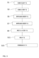
図3は、本発明の一実施形態による、測定セル23内溶液中の物質の吸光度を測定するための方法のフローチャートを示した図である。本方法は、ここでも図2を参照しながら以下に記載するステップを含む。
FIG. 3 shows a flow chart of a method for measuring the absorbance of a substance in solution in measuring
S1:光源25からの第1の光線27をビームスプリッタ29に向けて伝送する。
S1: Transmit the
S3:ビームスプリッタ29によって、第1の光線27を信号光線31および参照光線33に分割する。
S3: Split the
S5:信号光線31を第1の信号変調装置35で変調する。
S5: Modulate the
S7:参照光線33を第2の信号変調装置37で変調する。しかしながら、当該構造と、信号光線および参照光線間の距離とが許容するのであれば、第1および第2の信号変調装置35、37を同じ装置に組み込むことができる。
S7: Modulate the
本発明の一実施形態では、前記信号光線を変調するステップは、前記信号光線を第1の周波数で変調するステップを含み、前記参照光線を変調するステップは、前記第1の周波数とは異なる第2の周波数で前記参照光線を変調するステップを含む。また、信号光線および参照光線を変調するときに、前記信号光線および前記参照光線の両方に振幅変調を施す可能性がある。この振幅変調波形を、正弦波、矩形波、または任意の適切な波形とすることができる。 In one embodiment of the invention, modulating the signal beam comprises modulating the signal beam at a first frequency, and modulating the reference beam comprises modulating a second frequency different from the first frequency. modulating the reference beam at two frequencies. Also, when modulating the signal and reference beams, there is the possibility of subjecting both the signal and reference beams to amplitude modulation. This amplitude modulated waveform can be a sine wave, a square wave, or any suitable waveform.
S9:信号光線31が自身を通過するように、測定セル23を設ける。
S9: Place the measuring
S11:検出器39で信号を検出し、前記信号は、検出器39によって検出された信号光線31および参照光線33の合成信号強度である。
S11: Detect a signal at the
S15:検出器39によって検出された合成信号から、信号光線31および参照光線33の強度を再現するために、信号光線31および参照光線33に対して行われた前記変調に基づいて、前記検出信号の同期検波を行う。
S15: Based on the modulation performed on the
検出器39における信号光線31の検出と、同じ検出器39における参照光線33の検出とを、本方法を用いて同時に行うことができる。
Detection of the
一実施形態では、本方法は、信号光線31および参照光線33の両方を同じ検出器39によって検出できるように、少なくとも1つの光線方向転換装置41を使用して、前記信号光線および前記参照光線の一方または両方の方向を転換させるステップをさらに含む。別の代替例としては、上述のように光ファイバを使用する例が挙げられる。
In one embodiment, the method uses at least one
サンプルが測定セルを通って流れる用途では、前記測定セルをフローセルと呼んでいる。これは、たとえば流動中の物質の濃度を連続的に測定する必要がある、クロマトグラフィーシステム内に設けられている場合がある。このクロマトグラフィーシステムの例では、タンパク質の濃度をクロマトグラフィーカラムからの容出において測定することができる。このクロマトグラフィーカラムからの溶出物は、本発明による測定装置のフローセルを通って供給される。流動性サンプルで長く連続的な測定を行う状況にあっては、静的サンプルで測定を行う場合と比較して、装置内のドリフトに対してはるかに敏感になる。このため、本発明による方法および測定装置は、フローセル内に供給された溶液中の物質の吸光度を測定するのにとりわけ適している。 In applications in which the sample flows through a measuring cell, said measuring cell is called a flow cell. This may be provided, for example, in chromatography systems where the concentration of a substance in a stream needs to be measured continuously. In this chromatographic system example, protein concentration can be measured in the output from a chromatographic column. The eluate from this chromatography column is fed through the flow cell of the measuring device according to the invention. In situations where long continuous measurements are made on flowable samples, they are much more sensitive to drift in the instrument than when measurements are made on static samples. For this reason, the method and measuring device according to the invention are particularly suitable for measuring the absorbance of substances in solutions supplied in a flow cell.
1 測定装置
3 測定セル
5 光源
7 第1の光線
9 ビームスプリッタ
11 信号光線
13 参照光線
15 第1の検出器
17 第2の検出器
21、21’ 測定装置
23、23’ 測定セル
25、25’ 光源
27、27’ 第1の光線
29、29’ ビームスプリッタ
31、31’ 信号光線
33、33’ 参照光線
35、35’ 第1の信号変調装置
37、37’ 第2の信号変調装置
39、39’ 検出器
41 光線方向転換装置
43、43’ 処理装置
S1 ステップ
S3 ステップ
S5 ステップ
S7 ステップ
S9 ステップ
S11 ステップ
S15 ステップ
1 measuring
Claims (8)
‐光源(5、25、25’)からの第1の光線(7、27、27’)をビームスプリッタ(9、29、29’)に向けて伝送するステップ(S1)と、
‐前記ビームスプリッタ(9、29、29’)によって、前記第1の光線(7、27、27’)を信号光線(11、31、31’)および参照光線(13、33、33’)に分割するステップ(S3)と、
‐前記信号光線(11、31、31’)を第1の周波数で変調するステップ(S5)と、
‐前記参照光線(13、33、33’)を前記第1の周波数とは異なる第2の周波数で変調するステップ(S7)と、
‐前記信号光線(11、31、31’)が前記測定セル(3、23、23’)を通過するように、前記測定セル(3、23、23’)を設けるステップ(S9)と、
‐検出器(39、39’)で信号を検出するステップ(S11)であって、前記信号は、前記検出器(39、39’)によって検出された前記信号光線(11、31、31’)および前記参照光線(13、33、33’)の合成信号である、ステップ(S11)と、
‐前記検出器(39、39’)によって検出された前記合成信号から、前記信号光線(11、31、31’)および前記参照光線(13、33、33’)の強度を再現するために、前記検出器(39、39’)で検出された信号の同期検波を行うステップ(S15)であって、前記同期検波は、前記信号光線(11、31、31’)および前記参照光線(13、33、33’)に対して行われた前記変調に基づいている、ステップ(S15)と
を含み、
前記信号光線(11、31、31’)を変調するステップ(S5)と前記参照光線(13、33、33’)を変調するステップ(S7)の一方は、前記光源(5、25、25’)のオンオフを制御するステップを含み、前記信号光線(11、31、31’)を変調するステップ(S5)と前記参照光線(13、33、33’)を変調するステップ(S7)の他方は、光路のいずれかに設けられるシャッタ、可動ミラー、音叉、または灰色フィルタを用いて変調を行うステップを含み、
前記ビームスプリッタ(9、29、29’)は、前記第1の光線(7、27、27’)を信号光線(11、31、31’)および参照光線(13、33、33’)に分割する非対称ビームスプリッタ(9、29、29’)であり、前記第1の光線(7、27、27’)の大部分を、前記参照光線(13、33、33’)よりも前記信号光線(11、31、31’)に指向させ、
前記光源(5、25、25’)がオンであり且つ前記シャッタ、可動ミラー、音叉、または灰色フィルタがオンである際の前記合成信号の強度と前記光源(5、25、25’)がオンであり且つ前記シャッタ、可動ミラー、音叉、または灰色フィルタがオフである際の前記合成信号の強度との差を、前記光源(5、25、25’)がオフであり且つ前記シャッタ、可動ミラー、音叉、または灰色フィルタがオンである際の前記合成信号の強度に加算することによって、前記検出器(39、39’)において前記信号光線(11、31、31’)と前記参照光線(13、33、33’)が互いに区別される、方法。 A method for measuring the absorbance of a substance in a solution in a measuring cell (3, 23, 23'), said method comprising:
- transmitting (S1) a first light beam (7, 27, 27') from a light source (5, 25, 25') towards a beam splitter (9, 29, 29');
- by means of said beam splitter (9, 29, 29') said first beam (7, 27, 27') into a signal beam (11, 31, 31') and a reference beam (13, 33, 33'); a step of dividing (S3);
- modulating (S5) said signal beam (11, 31, 31') at a first frequency;
- modulating (S7) said reference beam (13, 33, 33') with a second frequency different from said first frequency;
- providing (S9) said measuring cell (3, 23, 23') such that said signal beam (11, 31, 31') passes through said measuring cell (3, 23, 23');
- detecting (S11) a signal with a detector (39, 39'), said signal being said signal beam (11, 31, 31') detected by said detector (39, 39'); and a composite signal of the reference beam (13, 33, 33'), step (S11);
- from the combined signal detected by the detector (39, 39'), to reconstruct the intensity of the signal beam (11, 31, 31') and the reference beam (13, 33, 33'), A step (S15) of performing synchronous detection of the signals detected by the detectors (39, 39'), wherein the synchronous detection includes the signal beams (11, 31, 31') and the reference beams (13, 13, 33, 33') based on said modulation performed on the step (S15);
One of the step (S5) of modulating the signal beam (11, 31, 31′) and the step (S7) of modulating the reference beam (13, 33, 33′) comprises: ), the other of the step (S5) of modulating the signal beam (11, 31, 31′) and the step (S7) of modulating the reference beam (13, 33, 33′) is , modulating with a shutter, a movable mirror, a tuning fork, or a gray filter provided in any of the optical paths;
The beam splitter (9, 29, 29') splits the first beam (7, 27, 27') into a signal beam (11, 31, 31') and a reference beam (13, 33, 33'). an asymmetric beamsplitter (9, 29, 29'), which directs a greater part of said first beam (7, 27, 27') than said reference beam (13, 33, 33') to said signal beam ( 11, 31, 31′) ,
intensity of said combined signal and said light source (5, 25, 25') when said light source (5, 25, 25') is on and said shutter, movable mirror, tuning fork, or gray filter is on and the difference from the intensity of the synthesized signal when the shutter, movable mirror, tuning fork, or gray filter is off, when the light source (5, 25, 25') is off and the shutter, movable mirror , tuning fork or gray filter is on, the signal beam (11, 31, 31′) and the reference beam (13 , 33, 33′) are distinguished from each other .
‐第1の光線(7、27、27’)を伝送する光源(5、25、25’)と、
‐前記第1の光線(7、27、27’)が、自身によって信号光線(11、31、31’)および参照光線(13、33、33’)に分割されるように設けられたビームスプリッタ(9、29、29’)と、
‐前記信号光線(11、31、31’)が、自身を通過するように配置された前記測定セル(3、23、23’)と、
‐前記信号光線(11、31、31’)を第1の周波数で変調するように構成された第1の信号変調装置(35、35’)と、
‐前記参照光線(13、33、33’)を前記第1の周波数とは異なる第2の周波数で変調するように構成された第2の信号変調装置(37、37’)と、
‐前記信号光線(11、31、31’)が変調されて前記測定セル(3、23、23’)を通過したときに、前記信号光線(11、31、31’)を検出し、また前記参照光線(13、33、33’)が変調されたときに、前記参照光線(13、33、33’)も検出するように構成された検出器(39、39’)であって、前記検出器(39、39’)は、前記検出器(39、39’)によって検出された合成信号から、前記信号光線(11、31、31’)および前記参照光線(13、33、33’)の強度を再現するために、前記信号光線(11、31、31’)および前記参照光線(13、33、33’)の合成信号の同期検波を行うように構成された処理装置(43、43’)を備えるか、またはこれに接続されており、前記同期検波は、前記信号光線(11、31、31’)および前記参照光線(13、33、33’)に対して行われた前記変調に基づいている、検出器(39、39’)と
を備え、
前記第1の信号変調装置(35、35’)と前記第2の信号変調装置(37、37’)の一方は、前記光源(5、25、25’)のオンオフを制御するように構成されていて、前記第1の信号変調装置(35、35’)と前記第2の信号変調装置(37、37’)の他方は、光路のいずれかに設けられるシャッタ、可動ミラー、音叉、または灰色フィルタであり、
前記ビームスプリッタ(9、29、29’)は、前記第1の光線(7、27、27’)を信号光線(11、31、31’)および参照光線(13、33、33’)に分割する非対称ビームスプリッタ(9、29、29’)であり、前記第1の光線(7、27、27’)の大部分を、前記参照光線(13、33、33’)よりも前記信号光線(11、31、31’)に指向させ、
前記光源(5、25、25’)がオンであり且つ前記シャッタ、可動ミラー、音叉、または灰色フィルタがオンである際の前記合成信号の強度と前記光源(5、25、25’)がオンであり且つ前記シャッタ、可動ミラー、音叉、または灰色フィルタがオフである際の前記合成信号の強度との差を、前記光源(5、25、25’)がオフであり且つ前記シャッタ、可動ミラー、音叉、または灰色フィルタがオンである際の前記合成信号の強度に加算することによって、前記検出器(39、39’)において前記信号光線(11、31、31’)と前記参照光線(13、33、33’)が互いに区別される、測定装置(1、21、21’)。 A measuring device (1, 21, 21') for measuring the absorbance of a substance in a solution in an internal measuring cell (3, 23, 23'), said measuring device (1, 21, 21') comprising ,
- a light source (5, 25, 25') transmitting the first light beam (7, 27, 27');
- a beam splitter arranged by itself to split said first beam (7, 27, 27') into a signal beam (11, 31, 31') and a reference beam (13, 33, 33'); (9, 29, 29′) and
- said measuring cell (3, 23, 23') arranged such that said signal beam (11, 31, 31') passes through it;
- a first signal modulator (35, 35') configured to modulate said signal beam (11, 31, 31') at a first frequency;
- a second signal modulator (37, 37') arranged to modulate said reference beam (13, 33, 33') at a second frequency different from said first frequency;
- detecting said signal beam (11, 31, 31') when it has been modulated and passed through said measuring cell (3, 23, 23'); a detector (39, 39') configured to also detect said reference beam (13, 33, 33') when said reference beam (13, 33, 33') is modulated, said detecting A detector (39, 39') selects from the combined signal detected by said detector (39, 39') the signal beam (11, 31, 31') and the reference beam (13, 33, 33'). a processing unit (43, 43') adapted to perform coherent detection of the combined signal of said signal beam (11, 31, 31') and said reference beam (13, 33, 33') in order to reproduce the intensity; ), wherein the synchronous detection is applied to the modulation performed on the signal beam (11, 31, 31′) and the reference beam (13, 33, 33′). a detector (39, 39') based on
One of said first signal modulating device (35, 35') and said second signal modulating device (37, 37') is configured to control on/off of said light source (5, 25, 25'). and the other of said first signal modulating device (35, 35') and said second signal modulating device (37, 37') is a shutter, a movable mirror, a tuning fork, or a gray is a filter,
The beam splitter (9, 29, 29') splits the first beam (7, 27, 27') into a signal beam (11, 31, 31') and a reference beam (13, 33, 33'). an asymmetric beamsplitter (9, 29, 29'), which directs a greater part of said first beam (7, 27, 27') than said reference beam (13, 33, 33') to said signal beam ( 11, 31, 31′) ,
intensity of said combined signal and said light source (5, 25, 25') when said light source (5, 25, 25') is on and said shutter, movable mirror, tuning fork, or gray filter is on and the difference from the intensity of the synthesized signal when the shutter, movable mirror, tuning fork, or gray filter is off, when the light source (5, 25, 25') is off and the shutter, movable mirror , tuning fork or gray filter is on, the signal beam (11, 31, 31′) and the reference beam (13 , 33, 33') are distinguished from each other .
Applications Claiming Priority (3)
| Application Number | Priority Date | Filing Date | Title |
|---|---|---|---|
| GBGB1612010.7A GB201612010D0 (en) | 2016-07-11 | 2016-07-11 | A method and a measuring device for measuring the absorbance of a substance in a solution |
| GB1612010.7 | 2016-07-11 | ||
| PCT/EP2017/065912 WO2018010956A1 (en) | 2016-07-11 | 2017-06-27 | A method for measuring the absorbance of a substance in a solution and a measuring device therefor |
Publications (2)
| Publication Number | Publication Date |
|---|---|
| JP2019522202A JP2019522202A (en) | 2019-08-08 |
| JP7308744B2 true JP7308744B2 (en) | 2023-07-14 |
Family
ID=56890840
Family Applications (1)
| Application Number | Title | Priority Date | Filing Date |
|---|---|---|---|
| JP2019500830A Active JP7308744B2 (en) | 2016-07-11 | 2017-06-27 | Method and apparatus for measuring absorbance of substance in solution |
Country Status (6)
| Country | Link |
|---|---|
| US (2) | US11815451B2 (en) |
| EP (2) | EP4563997A3 (en) |
| JP (1) | JP7308744B2 (en) |
| CN (2) | CN109477792A (en) |
| GB (1) | GB201612010D0 (en) |
| WO (1) | WO2018010956A1 (en) |
Families Citing this family (4)
| Publication number | Priority date | Publication date | Assignee | Title |
|---|---|---|---|---|
| CN112902835A (en) * | 2019-12-04 | 2021-06-04 | 阳程科技股份有限公司 | Optical alignment detection device and detection method thereof |
| DE102020209268B3 (en) * | 2020-07-22 | 2021-10-14 | Hochschule Emden/Leer | Optical system |
| CN116106230B (en) * | 2022-12-29 | 2026-01-30 | 南京港能环境科技有限公司 | A dual-channel environmental detection signal processing circuit and a medium concentration detection system |
| CN119757205A (en) * | 2024-12-24 | 2025-04-04 | 中国科学院西安光学精密机械研究所 | Compact UV Dual-Path Optical System for Seawater Nitrate Concentration Measurement |
Citations (2)
| Publication number | Priority date | Publication date | Assignee | Title |
|---|---|---|---|---|
| JP2007093410A (en) | 2005-09-29 | 2007-04-12 | Shimadzu Corp | Spectrophotometer |
| US20080087078A1 (en) | 2005-11-14 | 2008-04-17 | Schlumberger Technology Corporation | Logging System and Method for In-Situ Fluids Sensing Through Optical Fiber With Attenuation Compensation |
Family Cites Families (27)
| Publication number | Priority date | Publication date | Assignee | Title |
|---|---|---|---|---|
| US3834821A (en) | 1971-01-12 | 1974-09-10 | Damon Corp | Multiple photometer assembly |
| US4008394A (en) | 1973-06-28 | 1977-02-15 | Sensors, Inc. | Gas analyzing |
| JPS5348055B2 (en) | 1973-12-07 | 1978-12-26 | ||
| JPS51136472A (en) * | 1975-05-20 | 1976-11-25 | Sanyo Electric Co Ltd | Absorbing type gas density measuring |
| JPS56150332A (en) | 1980-04-24 | 1981-11-20 | Fujitsu Ltd | Infrared spectroscopic analysis method |
| SU1114150A1 (en) | 1982-10-25 | 1991-06-30 | Институт физики АН БССР | Double-channel gas analyzer |
| JPS59107221A (en) * | 1982-12-11 | 1984-06-21 | Japan Spectroscopic Co | Spectrophotometer |
| JPS6093945A (en) * | 1983-10-28 | 1985-05-25 | Shimadzu Corp | Transmission loss compensation method for optical transmission measuring equipment |
| SU1356703A1 (en) | 1985-07-01 | 1991-06-30 | Институт физики АН БССР | Optical gas analyzer |
| SU1398589A1 (en) | 1986-03-18 | 1991-06-30 | Институт физики АН БССР | Gas analyzer |
| SU1462986A1 (en) | 1986-04-07 | 1991-03-23 | Институт физики АН БССР | Gas analiser |
| DE69121633T2 (en) * | 1990-05-22 | 1997-01-16 | Tsutomu Ichimura | Method and apparatus for measuring spectral absorption in opaque material and method and apparatus for measuring a distribution of microscopic absorption |
| US5504337A (en) * | 1990-10-10 | 1996-04-02 | Joseph R. Lakowicz | Method and apparatus for performing phase fluorescence lifetime measurements in flow cytometry |
| JP2973639B2 (en) | 1991-09-30 | 1999-11-08 | 横河電機株式会社 | Equipment for measuring characteristics of sheet-like objects |
| JP2000019108A (en) * | 1998-07-06 | 2000-01-21 | Horiba Ltd | Infrared gas analyzer |
| JP2005301202A (en) * | 2004-03-19 | 2005-10-27 | Fuji Xerox Co Ltd | Holographic recording medium and holographic recording method using the same |
| US7468788B2 (en) * | 2005-06-21 | 2008-12-23 | Stheno Corporation | Systems and methods for chiral detection and analysis |
| GB0524225D0 (en) | 2005-11-29 | 2006-01-04 | Amersham Biosciences Ab | Methods and apparatus for detecting and measuring the concentration of a substance in a solution |
| CN101561391A (en) * | 2009-06-04 | 2009-10-21 | 中国航空工业集团公司西安飞机设计研究所 | Gas concentration measuring device and measuring method thereof |
| EP2449354B1 (en) * | 2009-07-30 | 2020-06-03 | Halliburton Energy Services Inc. | Energy intensity transformation |
| WO2011093775A1 (en) * | 2010-01-28 | 2011-08-04 | Ge Healthcare Bio-Sciences Ab | Optical flow cell detector |
| GB201209738D0 (en) | 2012-05-31 | 2012-07-18 | Ge Healthcare Bio Sciences Ab | Methods and apparatus for measuring the concentration of a substance in a solution |
| US9164032B2 (en) * | 2012-12-31 | 2015-10-20 | Omni Medsci, Inc. | Short-wave infrared super-continuum lasers for detecting counterfeit or illicit drugs and pharmaceutical process control |
| US20140361172A1 (en) * | 2013-06-11 | 2014-12-11 | Jp3 Measurement, Llc | Detection of h2s in natural gas and hydrocarbon streams using a dual-path near-ir spectroscopy system |
| JP2016530546A (en) * | 2013-09-24 | 2016-09-29 | ジーイー・ヘルスケア・バイオサイエンス・アクチボラグ | Light absorption monitor system |
| CN103698295B (en) * | 2013-12-20 | 2016-03-02 | 中国科学技术大学 | A kind of miniature far infrared gas concentration inspect method and device |
| US9772287B2 (en) * | 2014-04-16 | 2017-09-26 | Saudi Arabian Oil Company | Sensor for monitoring for the presence and measurement of aqueous aldehyde biocides |
-
2016
- 2016-07-11 GB GBGB1612010.7A patent/GB201612010D0/en not_active Ceased
-
2017
- 2017-06-27 US US16/316,276 patent/US11815451B2/en active Active
- 2017-06-27 JP JP2019500830A patent/JP7308744B2/en active Active
- 2017-06-27 WO PCT/EP2017/065912 patent/WO2018010956A1/en not_active Ceased
- 2017-06-27 CN CN201780043398.9A patent/CN109477792A/en active Pending
- 2017-06-27 EP EP25162158.7A patent/EP4563997A3/en active Pending
- 2017-06-27 CN CN202510602453.XA patent/CN120385639A/en active Pending
- 2017-06-27 EP EP17735452.9A patent/EP3482190B1/en active Active
-
2023
- 2023-10-04 US US18/481,117 patent/US12276601B2/en active Active
Patent Citations (2)
| Publication number | Priority date | Publication date | Assignee | Title |
|---|---|---|---|---|
| JP2007093410A (en) | 2005-09-29 | 2007-04-12 | Shimadzu Corp | Spectrophotometer |
| US20080087078A1 (en) | 2005-11-14 | 2008-04-17 | Schlumberger Technology Corporation | Logging System and Method for In-Situ Fluids Sensing Through Optical Fiber With Attenuation Compensation |
Also Published As
| Publication number | Publication date |
|---|---|
| CN120385639A (en) | 2025-07-29 |
| CN109477792A (en) | 2019-03-15 |
| EP4563997A3 (en) | 2025-08-06 |
| EP3482190A1 (en) | 2019-05-15 |
| EP4563997A2 (en) | 2025-06-04 |
| GB201612010D0 (en) | 2016-08-24 |
| WO2018010956A1 (en) | 2018-01-18 |
| US20190323953A1 (en) | 2019-10-24 |
| JP2019522202A (en) | 2019-08-08 |
| US11815451B2 (en) | 2023-11-14 |
| US20240027337A1 (en) | 2024-01-25 |
| EP3482190B1 (en) | 2025-05-14 |
| US12276601B2 (en) | 2025-04-15 |
Similar Documents
| Publication | Publication Date | Title |
|---|---|---|
| US12276601B2 (en) | Method for measuring the absorbance of a substance in a solution and a measuring device therefor | |
| US12352685B2 (en) | Apparatus and method for measuring the light absorbance of a substance in a solution | |
| JP2016033484A (en) | Optical system for branching reference light | |
| JP6062837B2 (en) | Detector for liquid chromatography | |
| JPS6337339B2 (en) | ||
| CN104198385A (en) | Eight-channel device for detecting switchable light source absorption spectrum | |
| US11982620B2 (en) | Multi-capillary optical detection system | |
| CN102753949B (en) | Spectrophotometer and its performance measurement method | |
| CN102288580A (en) | Protein turbidity comparator with double light sources and four passages | |
| US11499913B2 (en) | Method and device for measuring absorbance of a substance in solution with multiple light rays | |
| JP2004340833A (en) | Optical measuring device | |
| US20180231511A1 (en) | Detector for liquid chromatography | |
| JPH11101739A (en) | Ellipsometry apparatus | |
| KR20170002840A (en) | Photo detector for measuring a multi-wavelength | |
| CN219957308U (en) | Multi-channel capillary electrophoresis detection system | |
| CN111693460A (en) | Detection apparatus based on polarized light beam saturated absorption spectrum | |
| RU2012868C1 (en) | Single-beam multichannel analyzer | |
| KR20220114111A (en) | Apparatus for measuring concentration of target material using multi-port oprical fiber coupler based optical interferometer | |
| JP2000074820A (en) | Liquid chromatograph | |
| KR20240043447A (en) | Spectormeter apparatus for multi-signal measurement | |
| JPH0210372B2 (en) | ||
| WO2018003045A1 (en) | Beam splitter with aperture function, and detector provided with said beam splitter | |
| RU2021104150A (en) | DEVICE FOR MEASURING THE FLOW OF A SUBSTANCE BY LIGHT ABSORPTION AND THE CORRESPONDING MEASUREMENT METHOD | |
| JPH05307001A (en) | Absorbed / scattered light measuring device | |
| Hall | Rotoreflected double-beam thermal lens spectrometry and simultaneous thermal lens and fluorescence detection for high performance microbore liquid chromatography |
Legal Events
| Date | Code | Title | Description |
|---|---|---|---|
| RD03 | Notification of appointment of power of attorney |
Free format text: JAPANESE INTERMEDIATE CODE: A7423 Effective date: 20190521 |
|
| A521 | Request for written amendment filed |
Free format text: JAPANESE INTERMEDIATE CODE: A523 Effective date: 20190527 |
|
| RD04 | Notification of resignation of power of attorney |
Free format text: JAPANESE INTERMEDIATE CODE: A7424 Effective date: 20190527 |
|
| A621 | Written request for application examination |
Free format text: JAPANESE INTERMEDIATE CODE: A621 Effective date: 20200610 |
|
| A977 | Report on retrieval |
Free format text: JAPANESE INTERMEDIATE CODE: A971007 Effective date: 20210430 |
|
| A131 | Notification of reasons for refusal |
Free format text: JAPANESE INTERMEDIATE CODE: A131 Effective date: 20210510 |
|
| A521 | Request for written amendment filed |
Free format text: JAPANESE INTERMEDIATE CODE: A523 Effective date: 20210714 |
|
| A131 | Notification of reasons for refusal |
Free format text: JAPANESE INTERMEDIATE CODE: A131 Effective date: 20220104 |
|
| A521 | Request for written amendment filed |
Free format text: JAPANESE INTERMEDIATE CODE: A523 Effective date: 20220311 |
|
| A02 | Decision of refusal |
Free format text: JAPANESE INTERMEDIATE CODE: A02 Effective date: 20220801 |
|
| A521 | Request for written amendment filed |
Free format text: JAPANESE INTERMEDIATE CODE: A523 Effective date: 20220914 |
|
| C60 | Trial request (containing other claim documents, opposition documents) |
Free format text: JAPANESE INTERMEDIATE CODE: C60 Effective date: 20220914 |
|
| A911 | Transfer to examiner for re-examination before appeal (zenchi) |
Free format text: JAPANESE INTERMEDIATE CODE: A911 Effective date: 20221005 |
|
| C21 | Notice of transfer of a case for reconsideration by examiners before appeal proceedings |
Free format text: JAPANESE INTERMEDIATE CODE: C21 Effective date: 20221011 |
|
| A131 | Notification of reasons for refusal |
Free format text: JAPANESE INTERMEDIATE CODE: A131 Effective date: 20230104 |
|
| A521 | Request for written amendment filed |
Free format text: JAPANESE INTERMEDIATE CODE: A523 Effective date: 20230317 |
|
| TRDD | Decision of grant or rejection written | ||
| A01 | Written decision to grant a patent or to grant a registration (utility model) |
Free format text: JAPANESE INTERMEDIATE CODE: A01 Effective date: 20230605 |
|
| A61 | First payment of annual fees (during grant procedure) |
Free format text: JAPANESE INTERMEDIATE CODE: A61 Effective date: 20230704 |
|
| R150 | Certificate of patent or registration of utility model |
Ref document number: 7308744 Country of ref document: JP Free format text: JAPANESE INTERMEDIATE CODE: R150 |