JP7274401B2 - honeycomb structure - Google Patents
honeycomb structure Download PDFInfo
- Publication number
- JP7274401B2 JP7274401B2 JP2019220598A JP2019220598A JP7274401B2 JP 7274401 B2 JP7274401 B2 JP 7274401B2 JP 2019220598 A JP2019220598 A JP 2019220598A JP 2019220598 A JP2019220598 A JP 2019220598A JP 7274401 B2 JP7274401 B2 JP 7274401B2
- Authority
- JP
- Japan
- Prior art keywords
- honeycomb
- recess
- segment
- length
- honeycomb segment
- Prior art date
- Legal status (The legal status is an assumption and is not a legal conclusion. Google has not performed a legal analysis and makes no representation as to the accuracy of the status listed.)
- Active
Links
- 238000005192 partition Methods 0.000 claims description 14
- 239000012530 fluid Substances 0.000 claims description 6
- 238000004519 manufacturing process Methods 0.000 description 29
- 239000000463 material Substances 0.000 description 18
- 238000000034 method Methods 0.000 description 15
- 230000004323 axial length Effects 0.000 description 13
- 230000002093 peripheral effect Effects 0.000 description 10
- 238000011161 development Methods 0.000 description 9
- 230000018109 developmental process Effects 0.000 description 9
- 238000011156 evaluation Methods 0.000 description 9
- 230000000052 comparative effect Effects 0.000 description 7
- 239000004927 clay Substances 0.000 description 6
- 229910010271 silicon carbide Inorganic materials 0.000 description 6
- 239000002131 composite material Substances 0.000 description 5
- 238000001035 drying Methods 0.000 description 5
- 239000013618 particulate matter Substances 0.000 description 5
- HBMJWWWQQXIZIP-UHFFFAOYSA-N silicon carbide Chemical compound [Si+]#[C-] HBMJWWWQQXIZIP-UHFFFAOYSA-N 0.000 description 5
- 239000003054 catalyst Substances 0.000 description 4
- 238000010438 heat treatment Methods 0.000 description 4
- 238000000746 purification Methods 0.000 description 4
- 239000002994 raw material Substances 0.000 description 4
- 238000000926 separation method Methods 0.000 description 4
- 238000012360 testing method Methods 0.000 description 4
- XUIMIQQOPSSXEZ-UHFFFAOYSA-N Silicon Chemical compound [Si] XUIMIQQOPSSXEZ-UHFFFAOYSA-N 0.000 description 3
- 238000005520 cutting process Methods 0.000 description 3
- 238000000227 grinding Methods 0.000 description 3
- 239000000843 powder Substances 0.000 description 3
- SBEQWOXEGHQIMW-UHFFFAOYSA-N silicon Chemical compound [Si].[Si] SBEQWOXEGHQIMW-UHFFFAOYSA-N 0.000 description 3
- 239000010703 silicon Substances 0.000 description 3
- 229910052710 silicon Inorganic materials 0.000 description 3
- 230000008646 thermal stress Effects 0.000 description 3
- 239000011230 binding agent Substances 0.000 description 2
- 230000033228 biological regulation Effects 0.000 description 2
- 229910052878 cordierite Inorganic materials 0.000 description 2
- 230000003247 decreasing effect Effects 0.000 description 2
- 238000010304 firing Methods 0.000 description 2
- 229910052751 metal Inorganic materials 0.000 description 2
- 239000002184 metal Substances 0.000 description 2
- 229910000505 Al2TiO5 Inorganic materials 0.000 description 1
- OKTJSMMVPCPJKN-UHFFFAOYSA-N Carbon Chemical compound [C] OKTJSMMVPCPJKN-UHFFFAOYSA-N 0.000 description 1
- 229910052581 Si3N4 Inorganic materials 0.000 description 1
- JFBZPFYRPYOZCQ-UHFFFAOYSA-N [Li].[Al] Chemical compound [Li].[Al] JFBZPFYRPYOZCQ-UHFFFAOYSA-N 0.000 description 1
- 230000001133 acceleration Effects 0.000 description 1
- 239000000853 adhesive Substances 0.000 description 1
- 230000001070 adhesive effect Effects 0.000 description 1
- PNEYBMLMFCGWSK-UHFFFAOYSA-N aluminium oxide Inorganic materials [O-2].[O-2].[O-2].[Al+3].[Al+3] PNEYBMLMFCGWSK-UHFFFAOYSA-N 0.000 description 1
- 229910052799 carbon Inorganic materials 0.000 description 1
- 238000002485 combustion reaction Methods 0.000 description 1
- 238000012790 confirmation Methods 0.000 description 1
- 238000007604 dielectric heating drying Methods 0.000 description 1
- JSKIRARMQDRGJZ-UHFFFAOYSA-N dimagnesium dioxido-bis[(1-oxido-3-oxo-2,4,6,8,9-pentaoxa-1,3-disila-5,7-dialuminabicyclo[3.3.1]nonan-7-yl)oxy]silane Chemical compound [Mg++].[Mg++].[O-][Si]([O-])(O[Al]1O[Al]2O[Si](=O)O[Si]([O-])(O1)O2)O[Al]1O[Al]2O[Si](=O)O[Si]([O-])(O1)O2 JSKIRARMQDRGJZ-UHFFFAOYSA-N 0.000 description 1
- KZHJGOXRZJKJNY-UHFFFAOYSA-N dioxosilane;oxo(oxoalumanyloxy)alumane Chemical compound O=[Si]=O.O=[Si]=O.O=[Al]O[Al]=O.O=[Al]O[Al]=O.O=[Al]O[Al]=O KZHJGOXRZJKJNY-UHFFFAOYSA-N 0.000 description 1
- 230000000694 effects Effects 0.000 description 1
- 238000005516 engineering process Methods 0.000 description 1
- 238000001125 extrusion Methods 0.000 description 1
- 238000007602 hot air drying Methods 0.000 description 1
- QSHDDOUJBYECFT-UHFFFAOYSA-N mercury Chemical compound [Hg] QSHDDOUJBYECFT-UHFFFAOYSA-N 0.000 description 1
- 229910052753 mercury Inorganic materials 0.000 description 1
- 150000002739 metals Chemical class 0.000 description 1
- 238000002156 mixing Methods 0.000 description 1
- 239000000203 mixture Substances 0.000 description 1
- 238000012986 modification Methods 0.000 description 1
- 230000004048 modification Effects 0.000 description 1
- 239000004570 mortar (masonry) Substances 0.000 description 1
- 229910052863 mullite Inorganic materials 0.000 description 1
- 239000002245 particle Substances 0.000 description 1
- 238000002459 porosimetry Methods 0.000 description 1
- 230000000644 propagated effect Effects 0.000 description 1
- AABBHSMFGKYLKE-SNAWJCMRSA-N propan-2-yl (e)-but-2-enoate Chemical compound C\C=C\C(=O)OC(C)C AABBHSMFGKYLKE-SNAWJCMRSA-N 0.000 description 1
- 230000035939 shock Effects 0.000 description 1
- HQVNEWCFYHHQES-UHFFFAOYSA-N silicon nitride Chemical compound N12[Si]34N5[Si]62N3[Si]51N64 HQVNEWCFYHHQES-UHFFFAOYSA-N 0.000 description 1
- 238000007711 solidification Methods 0.000 description 1
- 230000008023 solidification Effects 0.000 description 1
- 239000004071 soot Substances 0.000 description 1
- 229910052596 spinel Inorganic materials 0.000 description 1
- 239000011029 spinel Substances 0.000 description 1
- XLYOFNOQVPJJNP-UHFFFAOYSA-N water Substances O XLYOFNOQVPJJNP-UHFFFAOYSA-N 0.000 description 1
Images


Landscapes
- Ceramic Products (AREA)
- Catalysts (AREA)
- Exhaust Gas After Treatment (AREA)
- Processes For Solid Components From Exhaust (AREA)
- Filtering Of Dispersed Particles In Gases (AREA)
Description
本発明は、ハニカム構造体に関する。更に詳しくは、排ガス中に含まれる粒子状物質を捕集するためのフィルタや触媒を担持して排ガスを浄化するための触媒担体等に使用されるハニカム構造体に関する。 The present invention relates to a honeycomb structure. More specifically, the present invention relates to a honeycomb structure used as a filter for collecting particulate matter contained in exhaust gas, a catalyst carrier for carrying a catalyst to purify exhaust gas, and the like.
ディーゼル車やトラックから排出される排ガス中には、粒子状物質が含まれている。以下、粒子状物質を、「PM」ということがある。PMは、「Particulate Matter」の略である。このPMは、主にスート(煤)等のカーボン微粒子からなるもので、大気中に放出されるのを防止する必要があり、厳しい排出規制が課せられている。 Exhaust gas emitted from diesel vehicles and trucks contains particulate matter. Hereinafter, particulate matter may be referred to as "PM". PM is an abbreviation for "Particulate Matter". This PM mainly consists of fine carbon particles such as soot, and must be prevented from being released into the atmosphere, and strict emission regulations are imposed.
このような厳しい排出規制に対応すべく、PM排出量を低減するための多くの研究が行われているが、PM排出量を燃焼技術の改善によって低減するには限界があり、排気系にフィルタを設置することが、有効なPM排出量の低減手段となっている。 Many studies have been conducted to reduce PM emissions in order to comply with such strict emission regulations, but there is a limit to how much PM emissions can be reduced by improving combustion technology. is an effective means of reducing PM emissions.
PMを捕集するためのフィルタとしては、圧力損失を許容範囲に抑えつつ、高いPM捕集効率を得られることから、ハニカム構造体を用いたウォールフロー型のものが、広く使用されている。ウォールフロー型フィルタに使用されるハニカム構造体は、排ガスの入口側となる流入端面から排ガスの出口側となる流出端面まで延びる複数のセルを区画形成する多孔質の隔壁を有している。このハニカム構造体に、所定のセルの流出端面側の開口端部及び残余のセルの流入端面側の開口端部を目封止する目封止部を設けることにより、高いPM捕集効率を持ったフィルタが得られる。 As a filter for trapping PM, a wall-flow type filter using a honeycomb structure is widely used because it can obtain high PM trapping efficiency while suppressing pressure loss within an allowable range. A honeycomb structure used in a wall-flow filter has porous partition walls defining and forming a plurality of cells extending from an inflow end face on the exhaust gas inlet side to an outflow end face on the exhaust gas outlet side. By providing the honeycomb structure with plugging portions for plugging the open ends of predetermined cells on the outflow end face side and the open ends of the remaining cells on the inflow end face side, the honeycomb structure has a high PM trapping efficiency. A good filter is obtained.
PMを捕集するためのフィルタに用いられるハニカム構造体は、近年、PMの捕集量を増大するため、高熱容量が見込まれる材料によって作製されることがある。但し、このような高熱容量が見込まれる材料は、概して熱膨張が高い特性であるが故に、高温の排ガスによる熱衝撃によって高い熱応力が発生し、ハニカム構造体が破損することがある。このようなことから、近年、フィルタを1つのハニカム構造体として製造するのではなく、複数個のハニカム形状のセグメント(ハニカムセグメント)を接合してハニカム構造体とすることが提案されている(例えば、特許文献1参照)。以下、このようなハニカム構造体を「セグメント構造のハニカム構造体」ということがある。セグメント構造のハニカム構造体は、1つのハニカム構造体が、複数個のハニカムセグメントによって分割された構造を有しているため、ハニカム構造体に生じる熱応力を分散させることができる。また、セグメント構造のハニカム構造体では、複数個のハニカムセグメントを接合する接合層が、熱応力を緩和する緩衝部材の役割を果すこともある。 In recent years, a honeycomb structure used for a filter for trapping PM is sometimes made of a material expected to have a high heat capacity in order to increase the trapping amount of PM. However, such a material expected to have a high heat capacity generally has a property of high thermal expansion, so that a high thermal stress may be generated by a thermal shock caused by high-temperature exhaust gas, and the honeycomb structure may be damaged. For this reason, in recent years, instead of manufacturing a filter as one honeycomb structure, it has been proposed to join a plurality of honeycomb-shaped segments (honeycomb segments) to form a honeycomb structure (for example, , see Patent Document 1). Hereinafter, such a honeycomb structure may be referred to as a "segment structure honeycomb structure". A honeycomb structure having a segment structure has a structure in which one honeycomb structure is divided by a plurality of honeycomb segments, so that thermal stress generated in the honeycomb structure can be dispersed. Moreover, in a honeycomb structure having a segment structure, a bonding layer that bonds a plurality of honeycomb segments may serve as a cushioning member that relaxes thermal stress.
セグメント構造のハニカム構造体は、ハニカムセグメント同士を接合層によって接合しているが、使用中において、ハニカムセグメント内の応力緩和のため、また、過大な熱応力が負荷されるなどの理由により、接合層自体にクラックが発生することがある。このような接合層のクラックが広範囲に及ぶと、クラックが流路方向全域まで貫通してしまい、ハニカムセグメント同士を保持できず、一部のハニカムセグメントが分離してしまうことがある。そして、分離したハニカムセグメントは、排ガスの風圧などによって下流側に押し出されて、ハニカム構造体から抜け落ちてしまうこともある。このような事象が発生すると、ハニカム構造体よりも下流側に設けられた排ガス浄化装置の後処理システムを物理的に損傷するなどの問題が発生する懸念がある。 In a honeycomb structure with a segmented structure, the honeycomb segments are joined together by a joining layer. Cracks may occur in the layer itself. If such cracks in the bonding layer extend over a wide range, the cracks penetrate all the way in the direction of the flow path, making it impossible to hold the honeycomb segments together and possibly causing separation of some of the honeycomb segments. Then, the separated honeycomb segment may be pushed downstream by the wind pressure of the exhaust gas or the like and drop out of the honeycomb structure. If such an event occurs, there is a concern that problems such as physical damage to the post-treatment system of the exhaust gas purifying device provided downstream of the honeycomb structure may occur.
本発明は、このような従来技術の有する問題点に鑑みてなされたものである。本発明は、接合層にクラックが発生した際に、そのクラックがハニカム構造体の全域に貫通し難く、クラックによるハニカムセグメントの分離を有効に抑制することが可能なハニカム構造体を提供する。 The present invention has been made in view of such problems of the prior art. The present invention provides a honeycomb structure in which, when a crack occurs in a bonding layer, the crack hardly penetrates the entire area of the honeycomb structure and can effectively suppress the separation of the honeycomb segments due to the crack.
本発明によれば、以下に示す、ハニカム構造体が提供される。 According to the present invention, a honeycomb structure described below is provided.
[1] 複数個の角柱状のハニカムセグメントと、複数個の前記ハニカムセグメントの側面同士を互いに接合する接合層と、を有するハニカムセグメント接合体を備え、
前記ハニカムセグメントは、流体の入口側となる第一端面から流体の出口側となる第二端面まで延びる複数のセルを取り囲むように配置された多孔質の隔壁と、前記ハニカムセグメントの側面を構成するセグメント外壁と、を有し、
複数個の前記ハニカムセグメントのうちの少なくとも2つの前記ハニカムセグメントは、前記ハニカムセグメントの一の側面に、内方に向けて窪んだ溝状の凹部を有し、
前記凹部は、前記ハニカムセグメントの前記第一端面又は前記第二端面のいずれか一方を起点とし、前記第一端面から前記第二端面に向かう軸方向に延びるように形成され、
前記ハニカムセグメント接合体において、前記凹部を有する2つの前記ハニカムセグメントは、互いの前記一の側面における前記凹部同士が対向するように隣り合って配置され、且つ、前記ハニカムセグメント接合体は、対向配置された2つの前記凹部の内部を架け渡すように2つの前記凹部に跨って配設された棒状の連結部材を更に有し、
前記連結部材の2つの前記凹部の内部に跨って延びる方向の長さを、前記連結部材の架け渡し方向長さH1とし、
対向配置された2つの前記凹部のうちの前記凹部の窪み方向の深さが最大となる部位における窪み深さを、前記凹部の窪み深さH2とし、
前記凹部の前記セルの延びる方向の両端位置における前記接合層の厚さのうちのより大きい方の前記接合層の厚さを、前記接合層の厚さH3とし、
前記連結部材の差し渡し方向長さH1が、前記凹部の窪み深さH2と前記接合層の厚さH3とを足し合わせた合計長さH4よりも大きく、
前記凹部の、前記第一端面から前記第二端面に向かう軸方向及び前記凹部の窪み方向のそれぞれに直交する横幅方向の長さW2が、前記ハニカムセグメントの前記一の側面の横幅方向の長さW1より小さく、
前記ハニカムセグメントの前記一の側面の平坦部と、溝状の前記凹部の側壁面とのなす角θ1が、60°以上である、ハニカム構造体。
[1] A bonded honeycomb segment body having a plurality of prismatic honeycomb segments and a bonding layer for bonding side surfaces of the plurality of honeycomb segments to each other,
The honeycomb segment comprises porous partition walls arranged so as to surround a plurality of cells extending from a first end face on a fluid inlet side to a second end face on a fluid outlet side, and side surfaces of the honeycomb segment. a segment outer wall;
at least two of the plurality of honeycomb segments have groove-like recesses that are recessed inward on one side surface of the honeycomb segment;
The concave portion is formed so as to extend in an axial direction from the first end surface toward the second end surface with either the first end surface or the second end surface of the honeycomb segment as a starting point,
In the honeycomb segment bonded body, two of the honeycomb segments having the recesses are arranged adjacent to each other such that the recesses on the one side faces of each other are opposed to each other, and the honeycomb segment bonded body is arranged to face each other. further comprising a rod-shaped connecting member disposed across the two recesses so as to bridge the interiors of the two recesses,
The length of the connecting member in the direction extending across the interior of the two recesses is defined as the bridging direction length H1 of the connecting member,
The recess depth at a portion of the two opposing recesses where the depth in the recess direction of the recess is maximum is defined as the recess depth H2 of the recess,
A thickness H3 of the bonding layer is defined as a larger thickness of the bonding layer among the thicknesses of the bonding layers at both end positions of the recess in the cell extending direction,
the length H1 in the spanning direction of the connecting member is greater than the total length H4 obtained by adding the depth H2 of the recess and the thickness H3 of the bonding layer;
The length W2 of the recess in the lateral width direction perpendicular to each of the axial direction from the first end face to the second end face and the depression direction of the recess is the lateral width direction length of the one side surface of the honeycomb segment. smaller than W1,
A honeycomb structure, wherein an angle θ1 formed between the flat portion of the one side surface of the honeycomb segment and the side wall surface of the groove-shaped concave portion is 60° or more.
[2] 前記ハニカムセグメントの前記凹部の窪み深さH2が、前記ハニカムセグメントの側面を構成する前記セグメント外壁の厚さより小さく、前記凹部が前記セグメント外壁を貫通していない、前記[1]に記載のハニカム構造体。 [2] The above [1], wherein the recess depth H2 of the recess of the honeycomb segment is smaller than the thickness of the segment outer wall forming the side surface of the honeycomb segment, and the recess does not penetrate the segment outer wall. honeycomb structure.
[3] 前記凹部の前記横幅方向の長さW2が、前記ハニカムセグメントの前記横幅方向の長さW1の20~70%である、前記[1]又は[2]に記載のハニカム構造体。 [3] The honeycomb structure according to [1] or [2], wherein the widthwise length W2 of the concave portion is 20 to 70% of the widthwise length W1 of the honeycomb segment.
[4] 前記凹部の前記軸方向の長さL2が、前記ハニカムセグメントの前記軸方向の長さL1の5~35%の長さである、前記[1]~[3]のいずれかに記載のハニカム構造体。 [4] According to any one of [1] to [3], wherein the axial length L2 of the concave portion is 5 to 35% of the axial length L1 of the honeycomb segment. honeycomb structure.
本発明のハニカム構造体は、従来のセグメント構造のハニカム構造体に比して、接合層にクラックが発生した際に、そのクラックがハニカム構造体の全域に貫通し難くもなるため、クラックによるハニカムセグメントの分離を有効に抑制することができる。このため、本発明のハニカム構造体は、ハニカムセグメントがクラックにより分離して、分離したハニカムセグメントが下流側に抜け落ちてしまうようなことが極めて生じにくい。 In the honeycomb structure of the present invention, when a crack occurs in the bonding layer, it is more difficult for the crack to penetrate the entire honeycomb structure than in a conventional honeycomb structure having a segment structure. Separation of segments can be effectively suppressed. Therefore, in the honeycomb structure of the present invention, it is extremely difficult for the honeycomb segments to separate due to cracks and the separated honeycomb segments to fall off downstream.
以下、本発明の実施の形態について説明するが、本発明は以下の実施の形態に限定されるものではない。したがって、本発明の趣旨を逸脱しない範囲で、当業者の通常の知識に基づいて、以下の実施の形態に対し適宜変更、改良等が加えられたものも本発明の範囲に入ることが理解されるべきである。 Embodiments of the present invention will be described below, but the present invention is not limited to the following embodiments. Therefore, it is understood that the following modifications, improvements, etc., to the following embodiments are also included in the scope of the present invention without departing from the spirit of the present invention, based on the ordinary knowledge of those skilled in the art. should.
(1)ハニカム構造体:
本発明のハニカム構造体の第一実施形態は、図1~図5に示すようなハニカム構造体100である。ここで、図1は、本発明のハニカム構造体の第一実施形態を模式的に示す斜視図である。図2は、図1に示すハニカム構造体の第一端面側を示す平面図である。図3は、図1に示すハニカム構造体の第二端面側を示す平面図である。図4は、図3のA-A’断面を模式的に示す断面図である。図5は、図3のB-B’断面を模式的に示す断面図である。
(1) Honeycomb structure:
A first embodiment of the honeycomb structure of the present invention is a
図1~図5に示すハニカム構造体100は、ハニカムセグメント接合体10、及びハニカムセグメント接合体10の外周を囲繞するように配置された外周壁13を備えた、セグメント構造のハニカム構造体100である。
The
ハニカムセグメント接合体10は、複数個の柱状のハニカムセグメント4と、複数個のハニカムセグメント4の側面同士を格子状に接合する接合層14と、を有している。ハニカムセグメント4は、流体の入口側となる第一端面11から流体の出口側となる第二端面12まで延びる複数のセル2を取り囲むように配置された多孔質の隔壁1と、ハニカムセグメント4の側面を構成するセグメント外壁3と、を有している。ハニカムセグメント4は、第一端面11及び第二端面12が四角形の四角柱状のものである。
The joined
複数個のハニカムセグメント4のうちの少なくとも2つのハニカムセグメント4は、図6に示すように、ハニカムセグメント4の一の側面に、内方に向けて窪んだ溝状の凹部8を有している。図6は、本発明のハニカム構造体の第一実施形態に用いられるハニカムセグメントを模式的に示す斜視図である。
At least two
図6に示すように、ハニカムセグメント4の凹部8は、ハニカムセグメント4の第一端面11又は第二端面12のいずれか一方を起点とし、第一端面11から第二端面12に向かう軸方向に延びるように形成されている。以下、本明細書において、特に断りのない限り、「軸方向」とは、ハニカムセグメント4の第一端面11から第二端面12に向かう方向を意味する。
As shown in FIG. 6, the recessed
図1~図5に示すハニカムセグメント接合体10において、凹部8を有する2つのハニカムセグメント4は、互いの一の側面における凹部8同士が対向するように隣り合って配置されている。そして、ハニカムセグメント接合体10は、対向配置された2つの凹部8の内部を架け渡すように2つの凹部8に跨って配設された棒状の連結部材7を更に有している。
In the honeycomb segment bonded
本実施形態のハニカム構造体100においては、ハニカムセグメント4の凹部8、及び2つの凹部8に跨って配設される連結部材7の構成について特に主要な特徴を有している。以下、凹部8及び連結部材7の構成についてより詳細に説明する。
The
まず、凹部8、連結部材7及び接合層14の寸法について、以下のように規定する。連結部材7の2つの凹部8の内部に跨って延びる方向の長さを、連結部材7の架け渡し方向長さH1とする。対向配置された2つの凹部8のうちの凹部8の窪み方向の深さが最大となる部位における窪み深さを、凹部8の窪み深さH2とする。凹部8のセル2の延びる方向の両端位置における接合層14の厚さのうちのより大きい方の前記接合層の厚さを、前記接合層の厚さH3とする。
First, the dimensions of the
連結部材7の差し渡し方向長さH1が、凹部8の窪み深さH2と接合層14の厚さH3とを足し合わせた合計長さH4よりも大きい。即ち、凹部8、連結部材7及び接合層14の各寸法は、下記式(1)の関係を満たす。
H1>H4=H2+H3 (1)
The spanwise length H1 of the connecting
H1>H4=H2+H3 (1)
また、凹部8の横幅方向の長さW2が、ハニカムセグメント4の一の側面の横幅方向の長さW1より小さい。ここで、凹部8の「横幅方向」とは、第一端面11から第二端面12に向かう軸方向及び凹部8の窪み方向のそれぞれに直交する方向のことを意味する。
Moreover, the widthwise length W2 of the
更に、ハニカムセグメント4の凹部8は、図7に示すように、ハニカムセグメント4の一の側面の平坦部17と、溝状の凹部8の側壁面15とのなす角θ1が、60°以上であるものとする。ここで、図7は、図3の一部を拡大した拡大平面図である。凹部8の「側壁面15」とは、ハニカムセグメント4の一の側面の平坦部17から内側に向かって屈曲した面である。具体的には、セグメント外壁3の一部が軸方向に切り欠かれることによって凹部8が形成されている場合、凹部8の「側壁面15」は、セグメント外壁3の切り欠き面となる。なお、凹部8がセグメント外壁3を貫通するように形成されている場合にも、上記なす角θ1を算出する際にも、セグメント外壁3の切り欠き面を「側壁面15」とする。
Further, as shown in FIG. 7, the
ハニカムセグメント4の凹部8の横幅方向の長さW2は、凹部8の窪み方向において一定でなくともよい。例えば、図6に示すハニカムセグメント4の凹部8は、軸方向に直交する面において、その形状が略長方形となり、その窪み方向において、横幅方向の長さW2が一定となっている。しかしながら、ハニカムセグメント4の凹部8は、軸方向に直交する面において、例えば、三角形や台形などの多角形、又は、半円状や半楕円などの形状であってよい。なお、連結部材7の形状については、ハニカムセグメント4の凹部8の形状に応じて適宜決定することができる。
The width W2 of the
図1~図5に示すようなハニカム構造体100は、従来のセグメント構造のハニカム構造体に比して、接合層14にクラックが発生した際に、そのクラックがハニカム構造体100の流路方向全域に貫通し難くもなる。このため、クラックによるハニカムセグメント4の分離を有効に抑制することができる。例えば、ハニカム構造体100は、ハニカムセグメント4がクラックにより分離して、分離したハニカムセグメント4が下流側に抜け落ちてしまうようなことが極めて生じにくい。また、例えば、連結部材7を配設した側の端面を下流側に向けて配置した場合には、仮に接合層14にクラックが発生して一部のハニカムセグメント4が分離したとしても、分離したハニカムセグメント4が下流側に抜け落ちてしまうことを防止することができる。
In the
凹部8の横幅方向の長さW2が、ハニカムセグメント4の横幅方向の長さW1の20~70%であることが好ましく、20~50%であることが更に好ましい。このように構成することによって、ハニカム構造体100の軸方向に直交する面におけるセル2の流路面積の減少を有効に抑制することができ、ハニカム構造体100の圧力損失の上昇を抑制することができる。
The widthwise length W2 of the
凹部8の軸方向の長さL2については特に制限はない。例えば、凹部8の軸方向の長さL2が、ハニカムセグメント4の軸方向の長さL1の5~35%の長さであると、流路面積減少を有効に抑制する点で好ましい。また、連結部材7の軸方向の長さは、凹部8の軸方向の長さL2と略同じであることが好ましい。
The length L2 of the
ハニカムセグメント4の一の側面の平坦部17と、凹部8の側壁面15とのなす角θ1は、60°以上であるが、60~120°であることが好ましく、90~110°であることが更に好ましい。なす角θ1が60°未満であると、凹部8内に、連結部材7が配置されずに、接合層14を形成する接合材によって占められる部位が増加するため圧損上昇の点で好ましくない。一方で、なす角θ1が120°を超えると、連結部材を配置できる深さが浅くなってしまう懸念がある点で好ましくない。
The angle θ1 formed by the
凹部8の窪み深さH2は、その内部に配設された連結部材7の差し渡し方向長さH1に対応し、この連結部材7が挿入され得る窪み深さを有していれば特に制限はない。凹部8の窪み深さH2としては、例えば、0.5~2.0mmであることが好ましく、0.5~1.5mmであることが更に好ましい。したがって、連結部材7の差し渡し方向長さH1は、接合層14の厚さH3に、上記した凹部8の窪み深さH2を足し合わせた合計長さH4よりも大きい長さであることが好ましい。
The recess depth H2 of the
凹部8は、例えば、ハニカムセグメント4の軸方向に沿って、凹部8の窪み深さH2が連続的又は段階的に変化していてもよい。例えば、ハニカムセグメント4の第二端面12を起点として軸方向に沿って形成された凹部8の場合、第二端面12側の窪み深さH2を相対的に浅くし、第一端面側に向かって、窪み深さH2が相対的に深くなっていてもよい。そして、連結部材7についても、凹部8の窪み深さH2に対応して、軸方向に沿って、連結部材7の架け渡し方向長さH1が変化するように構成されていてもよい。このように構成することによって、凹部8の内部に配設された連結部材7の脱落についても有効に抑制することができる。但し、例えば、凹部8の窪み深さH2が軸方向に沿って漸増する場合において、窪み深さH2の漸増量が大きすぎると、凹部8の窪み深さH2の最大値も大きく増加してしまうことがある。このため、例えば、第二端面12を起点として形成された凹部8において、軸方向に沿って窪み深さH2が漸増する場合には、第二端面12から見た漸増部位の仰角(別言すれば、末広がりの角度)が2°以下であることが好ましい。なお、第一端面11を起点として軸方向に沿って形成された凹部8も同様に、第一端面11から見た漸増部位の仰角(別言すれば、末広がりの角度)が2°以下であることが好ましい。また、連結部材7も同様に、軸方向に沿って連結部材7の架け渡し方向長さH1が漸増する場合には、漸増部位の仰角が2°以下であることが好ましい。
In the
凹部8の窪み深さH2は、ハニカムセグメント4のセグメント外壁3の厚さよりも小さくてもよいし、セグメント外壁3の厚さよりも大きくてもよい。ハニカム構造体100において、凹部8の窪み深さH2は、ハニカムセグメント4のセグメント外壁3の厚さよりも小さく、凹部8がセグメント外壁3を貫通しないように形成されていることが好ましい。例えば、凹部8の窪み深さH2が、セグメント外壁3の厚さよりも大きくなる形態としては、図9に示すようなハニカムセグメント44を挙げることができる。図9に示すハニカムセグメント44の詳細については後述するが、図9に示すハニカムセグメント44においては、凹部48が、ハニカムセグメント44のセグメント外壁43を貫通するように形成され、凹部48の一部が、ハニカムセグメント44内に形成された一部のセル2内まで到達している。
The recess depth H2 of the
ハニカムセグメント4に形成されているセル2の形状については特に制限はない。例えば、セル2の延びる方向に直交する断面における、セル2の形状としては、多角形、円形、楕円形等を挙げることができる。多角形としては、三角形、四角形、五角形、六角形、八角形等を挙げることができる。なお、セル2の形状は、三角形、四角形、五角形、六角形、八角形であることが好ましい。また、セル2の形状については、全てのセル2の形状が同一形状であってもよいし、異なる形状であってもよい。例えば、図示は省略するが、四角形のセルと、八角形のセルと混在したものであってもよい。また、セル2の大きさについては、全てのセル2の大きさが同じであってもよいし、異なっていてもよい。例えば、図示は省略するが、複数のセルのうち、一部のセルの大きさを大きくし、他のセルの大きさを相対的に小さくしてもよい。
The shape of the
隔壁1によって区画されるセル2のセル密度が、15~62個/cm2であることが好ましく、31~54個/cm2であることが更に好ましい。このように構成することによって、本実施形態のハニカム構造体100を、自動車のエンジンから排出される排ガスを浄化するための浄化部材(例えば、フィルタや触媒担体)として好適に利用することができる。
The cell density of the
隔壁1の気孔率が、30~75%であることが好ましく、35~70%であることが更に好ましく、40~65%であることが特に好ましい。隔壁1の気孔率は、水銀圧入法によって測定された値である。隔壁1の気孔率の測定は、例えば、Micromeritics社製のオートポア9500(商品名)を用いて行うことができる。気孔率の測定は、各ハニカムセグメント4の隔壁1の一部を切り出して試験片とし、その試験片を用いて行うことができる。隔壁1の気孔率が、30%未満であると、ハニカム構造体100自体の圧力損失が増大することや、触媒の担持後における圧力損失のばらつきが大きくなることがある。隔壁1の気孔率が、75%を超えると、ハニカム構造体100の強度が低下してしまうことがある。
The porosity of the
ハニカムセグメント4を構成する材料に特に制限はないが、強度、耐熱性、耐久性等の観点から、下記材料群から選択される少なくとも1種の材質が好ましい。材料群とは、炭化珪素、珪素-炭化珪素系複合材料、窒化珪素、コージェライト、ムライト、アルミナ、スピネル、炭化珪素-コージェライト系複合材料、リチウムアルミニウムシリケート、チタン酸アルミニウム、及びFe-Cr-Al系金属の材料群である。これらの中でも、炭化珪素、又は珪素-炭化珪素系複合材料が更に好ましい。珪素-炭化珪素系複合材料は、炭化珪素(SiC)を骨材とし、且つ珪素(Si)を結合材とする複合材料である。
Although there is no particular limitation on the material that constitutes the
ハニカムセグメント4の形状については、特に制限はない。なお、ハニカムセグメント4のうち、最外周に配置されたハニカムセグメント4は、ハニカム構造体100の全体形状に応じて、その一部が研削等により加工されていることが好ましい。また、最外周に配置されたハニカムセグメント4以外のハニカムセグメント4は、例えば、軸方向に直交する断面形状が四角形の角柱状であることが好ましい。
The shape of the
接合層14の材料については、特に制限はなく、従来公知のセグメント構造のハニカム構造体における接合層の材料を用いることができる。接合層14の最大厚さH1については特に制限はないが、例えば、0.5~3.0mmであることが好ましく、0.5~2.0mmであることが更に好ましく、0.5~1.5mmであることが特に好ましい。
The material of the
ハニカム構造体100の全体形状については、特に制限はない。例えば、図1に示すハニカム構造体100の全体形状は、第一端面11及び第二端面12が円形の円柱状である。その他、図示は省略するが、ハニカム構造体の全体形状としては、第一端面及び第二端面が、楕円形やレーストラック(Racetrack)形や長円形等の略円形の柱状であってもよい。また、ハニカム構造体の全体形状としては、第一端面及び第二端面が、四角形や六角形等の多角形の角柱状であってもよい。
The overall shape of the
ハニカム構造体100の大きさ、例えば、第一端面から第二端面までの長さや、ハニカム構造体100のセル2の延びる方向に直交する断面の大きさについては、特に制限はない。ハニカム構造体100を、排ガス浄化用のフィルタとして用いた際に、最適な浄化性能を得るように、各大きさを適宜選択すればよい。例えば、ハニカム構造体100の第一端面から第二端面までの長さは、100~300mmであることが好ましく、100~200mmであることが特に好ましい。また、ハニカム構造体100のセル2の延びる方向に直交する断面の面積は、15000~90000mm2であることが好ましく、20000~70000mm2であることが特に好ましい。
The size of the
ハニカム構造体100は、それぞれのハニカムセグメント4におけるセル2の第一端面11側又は第二端面12側のいずれか一方の端部が、目封止部5によって目封止されていてもよい。このように構成することによって、ハニカム構造体100を、排ガス中に含まれる粒子状物質を捕集除去するためにフィルタとして良好に利用することができる。目封止部5の材料については特に制限はない。目封止部5の材料は、例えば、ハニカムセグメント4を構成する材料として例示した材料と同様な材料が好ましい。
In the
次に、本発明のハニカム構造体の第二実施形態について、図8を参照しつつ説明する。図8は、本発明のハニカム構造体の第二実施形態に用いられるハニカムセグメントを模式的に示す斜視図である。図8において、図6に示すハニカムセグメント4と同様の構成要素については、同一の符号を付し、その説明を省略することがある。
Next, a second embodiment of the honeycomb structure of the present invention will be described with reference to FIG. FIG. 8 is a perspective view schematically showing honeycomb segments used in the second embodiment of the honeycomb structure of the present invention. In FIG. 8, the same components as those of the
第二実施形態のハニカム構造体(図示せず)においては、図8に示されるハニカムセグメント24によってハニカムセグメント接合体(図示せず)が形成されている。図8に示すハニカムセグメント24は、四角柱状の各側面を構成するセグメント外壁23に、軸方向に延びるような溝状の凹部28を有している。この凹部28は、第一端面11を起点とし、第二端面12を終点とし、ハニカムセグメント24の軸方向全域に亘って形成されている。
In the honeycomb structure (not shown) of the second embodiment, a honeycomb segment joined body (not shown) is formed by the
第二実施形態のハニカム構造体は、図8に示すようなハニカムセグメント24を用いてハニカムセグメント接合体が形成されている。具体的には、ハニカムセグメント接合体において、凹部28を有する2つのハニカムセグメント24は、互いの一の側面における凹部28同士が対向するように隣り合って配置されている。対向配置された2つの凹部28に跨って配設される棒状の連結部材(図示せず)は、例えば、ハニカムセグメント24の軸方向の長さL1と同じ軸方向長さのものとすることができる。
In the honeycomb structure of the second embodiment, a honeycomb segment joined body is formed using
図8に示すハニカムセグメント24に形成された凹部28は、例えば、軸方向に沿って、凹部28の窪み深さH2が連続的又は段階的に変化していてもよい。例えば、第一端面11側の窪み深さH2を深くし、第二端面12側の窪み深さH2を浅くしてもよい。また、第一端面11から第二端面12に向かう中間付近の窪み深さH2を最も深くし、第一端面11及び第二端面12に向かうにつれて窪み深さH2が浅くなってもよい。そして、連結部材(図示せず)についても、凹部28の窪み深さH2に対応して、軸方向に沿って、連結部材(図示せず)の架け渡し方向長さH1(図3参照)が変化するように構成されていてもよい。
In the
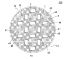
次に、第三実施形態のハニカム構造体について、図9及び図10を参照して説明する。図10に示すように、第三実施形態のハニカム構造体200は、図9に示されるハニカムセグメント44によってハニカムセグメント接合体50が形成されている。
Next, a honeycomb structure of a third embodiment will be described with reference to FIGS. 9 and 10. FIG. As shown in FIG. 10, in the
図9に示すハニカムセグメント44は、四角柱状の各側面を構成するセグメント外壁43に、内方に向けて窪んだ凹部48と、を有している。ハニカムセグメント44の凹部48は、第二端面12を起点とし、ハニカムセグメント44の軸方向に延びるように設けられている。ハニカムセグメント44の凹部48は、ハニカムセグメント44のセグメント外壁43を貫通し、ハニカムセグメント44の最外周のセル2まで到達するような窪み深さを有している。図10に示すように、凹部48の内部に配設された連結部材47の差し渡し方向長さは、上記した凹部48の窪み深さに対応したものとなっている。このように構成されたハニカム構造体200も、これまでに説明した第一実施形態のハニカム構造体100(図1~図5参照)と同様の効果を奏するものとなる。特に、本実施形態のハニカム構造体200は、ハニカムセグメントの抜け落ちをより有効に抑制することができる。
A
図9に示すハニカムセグメント44は、凹部48の窪み深さが異なること以外は、図6に示すハニカムセグメント4と同様に構成されていることが好ましい。図10に示すハニカム構造体200についても、図9に示されるようなハニカムセグメント44と、その凹部48の窪み深さに対応した連結部材47とが用いられていること以外は、これまでに説明した第一実施形態のハニカム構造体1000(図1~図5参照)と同様に構成されていることが好ましい。また、ハニカムセグメント44の凹部48については、ハニカムセグメント44の最外周のセル2を区画する外周側の隔壁1よりも内側まで窪んでいてもよい。
A
(2)ハニカム構造体の製造方法:
次に、本発明のハニカム構造体の製造方法について説明する。ハニカム構造体の製造方法としては、「ハニカムセグメント作製工程」と、「連結部材作製工程」と、「組立体作製工程」と、「接合体作製工程」と、を備えた方法を挙げることができる。
(2) Manufacturing method of honeycomb structure:
Next, a method for manufacturing a honeycomb structure of the present invention will be described. As a method for manufacturing a honeycomb structure, a method including a "honeycomb segment manufacturing process", a "connecting member manufacturing process", an "assembly manufacturing process", and a "bonded body manufacturing process" can be mentioned. .
ハニカムセグメント作製工程は、図6に示すような、複数のセル2を取り囲むように配置された多孔質の隔壁1、及び隔壁1を囲繞するように配置されたセグメント外壁3を有する角柱状のハニカムセグメント4を複数個作製する工程である。ハニカムセグメント作製工程は、従来公知のセグメント構造のハニカム構造体を製造する際における、ハニカムセグメントの作製方法に準じて行うことができる。
In the honeycomb segment manufacturing process, as shown in FIG. This is the step of producing a plurality of
また、ハニカムセグメント作製工程において、図6に示すような凹部8を有するハニカムセグメント4を作製する場合には、以下の方法によって、セグメント外壁3の表面に、所望の窪み深さH2の凹部8を形成する。具体的には、押出成形等の従来公知の方法でハニカムセグメントを作製し、作製したハニカムセグメントの側面を切削加工により研削して、所望の凹部8を形成する。
In the honeycomb segment manufacturing step, when manufacturing a
連結部材作製工程は、対向配置された2つの凹部の内部を架け渡すように配設される棒状の連結部材を作製する工程である。連結部材は、以下のようにして作製することができる。具体的には、連結部材の材質は、ハニカムセグメントと同一のものを用いることができる。作製方法としては、ハニカムセグメントと同じように坏土を所定の金型へ押し出すことにより成形し、得られた成形体を焼成することにより作製する方法を挙げることができる。 The connecting member manufacturing step is a step of manufacturing a rod-shaped connecting member that is disposed so as to bridge the insides of the two concave portions that are arranged opposite to each other. The connecting member can be produced as follows. Specifically, the same material as the honeycomb segment can be used for the connecting member. As a manufacturing method, there is a method of manufacturing by extruding clay into a predetermined mold and firing the obtained molded body in the same manner as the honeycomb segment.
組立体作製工程は、複数個のハニカムセグメントを格子状に組み合わせて、ハニカムセグメントの組立体を作製する工程である。より具体的には、組立体作製工程では、まず、ハニカムセグメントの側面(別言すれば、「セグメント外壁」)に接合用ペーストを塗工する。次に、複数個のハニカムセグメントを、互いの側面相互間に接合用ペーストを介在させた状態で格子状に組み合わせて、ハニカムセグメントの組立体を作製する。この際、凹部を有する2つのハニカムセグメントは、互いの凹部同士が対向するように、隣り合わせとなる位置に配置する。そして、2つのハニカムセグメントの対向配置された2つの凹部の内部には、2つの凹部の相互間を架け渡すように、棒状の連結部材を配設する。このようにして、複数個のハニカムセグメントを、格子状に順次組み合わせる。 The assembly production step is a step of producing an assembly of honeycomb segments by combining a plurality of honeycomb segments in a lattice. More specifically, in the assembly manufacturing process, first, a bonding paste is applied to the side surface of the honeycomb segment (in other words, the “outer wall of the segment”). Next, a plurality of honeycomb segments are combined in a grid pattern with bonding paste interposed between the side surfaces of the segments to produce a honeycomb segment assembly. At this time, the two honeycomb segments having the recesses are arranged at adjacent positions so that the recesses face each other. A rod-shaped connecting member is disposed inside the two recessed portions of the two honeycomb segments so as to bridge between the two recessed portions. In this manner, a plurality of honeycomb segments are sequentially combined in a grid pattern.
接合体作製工程は、ハニカムセグメントの組立体を乾燥させて、複数個のハニカムセグメントの側面同士を接合用ペーストによって接合して、ハニカムセグメントの接合体を作製する工程である。接合体作製工程は、主に、ハニカムセグメントの側面同士を接合する接合用ペーストを乾燥・固化させるための工程であり、乾燥・固化した接合用ペーストは、ハニカム構造体における接合層となり、この乾燥・固化により、接合層に所望の接合力が発現する。 The bonded body manufacturing step is a step of drying the honeycomb segment assembly and bonding the side surfaces of a plurality of honeycomb segments with a bonding paste to manufacture a bonded honeycomb segment body. The bonded body manufacturing process is mainly a process for drying and solidifying the bonding paste for bonding the side surfaces of the honeycomb segments.・The desired bonding strength is developed in the bonding layer by solidification.
乾燥の方法は特に制限はなく、例えば、マイクロ波加熱乾燥、高周波誘電加熱乾燥等の電磁波加熱方式と、熱風乾燥、過熱水蒸気乾燥等の外部加熱方式とを挙げることができる。これらの中でも、成形体全体を迅速かつ均一に、クラックが生じないように乾燥することができる点で、電磁波加熱方式で一定量の水分を乾燥させた後、残りの水分を外部加熱方式により乾燥させることが好ましい。 The drying method is not particularly limited, and examples thereof include electromagnetic heating methods such as microwave heating drying and high frequency dielectric heating drying, and external heating methods such as hot air drying and superheated steam drying. Among these, the entire molded body can be dried quickly and uniformly without cracks. It is preferable to let
接合体作製工程によって、ハニカムセグメントの接合体を作製した後、得られた接合体の外周部分を所望の形状となるように研削加工してもよい。例えば、このような研削加工を行うことにより、図1~図5に示すような、円柱状のハニカムセグメント接合体10を作製することができる。また、接合体の外周部分を研削加工した後、その外周面に外周コート層を配設して、ハニカム構造体100(図1参照)の外周壁13(図1参照)を作製してもよい。このような接合体作製工程以降の各製造工程については、例えば、従来公知のセグメント構造のハニカム構造体を製造する方法に準じて行うことができる。
After a joined body of honeycomb segments is produced by the joined body producing step, the peripheral portion of the joined body thus obtained may be ground so as to have a desired shape. For example, by performing such a grinding process, a cylindrical honeycomb segment joined
以下、本発明を実施例によって更に具体的に説明するが、本発明はこれらの実施例によって何ら限定されるものではない。 EXAMPLES Hereinafter, the present invention will be described in more detail with reference to Examples, but the present invention is not limited to these Examples.
(実施例1)
まず、ハニカムセグメントを作製するための坏土を調製するための原料粉末として、炭化珪素(SiC)粉末と金属珪素(Si)粉末とを混合した混合原料を準備した。そして、準備した混合原料に、バインダ、造孔材、及び水を適量加えて、可塑性の坏土を調製した。
(Example 1)
First, as raw material powder for preparing clay for manufacturing honeycomb segments, a mixed raw material was prepared by mixing silicon carbide (SiC) powder and metal silicon (Si) powder. Appropriate amounts of a binder, a pore-forming material, and water were added to the prepared mixed raw material to prepare a plastic clay.
次に、得られた坏土を、押出成形機を用いて成形し、四角柱状のハニカム成形体を49個作製した。 Next, the obtained clay was molded using an extruder to produce 49 rectangular prism-shaped honeycomb molded bodies.
次に、得られたハニカム成形体を高周波誘電加熱乾燥した後、熱風乾燥機を用いて更に乾燥した。次に、乾燥後のハニカムセグメント成形体のセルの端部に、セルの開口部が第一端面側と第二端面側とで交互に目封止されるように目封止部を配設した。 Next, the obtained honeycomb formed body was dried by high-frequency dielectric heating, and then further dried by using a hot air dryer. Next, plugging portions were provided at the end portions of the cells of the dried honeycomb segment formed body so that the opening portions of the cells were alternately plugged on the first end face side and the second end face side. .
次に、ハニカム成形体の各側面に形成した凹部の内部に配設するための棒状の連結部材を、以下の方法で作製した。連結部材の材質は、ハニカムセグメントと同一のものとした。ハニカムセグメントと同じように、連結部材を作製するための原料を用いて坏土を調製し、調製した坏土を所定の金型へ押出すことにより成形して、棒状の連結部材の成形体を作製した。その後、得られた成形体を焼成することにより、棒状の連結部材を作製した。連結部材は、架け渡し方向長さH1を2.1mmとし、その他は、凹部の軸方向の長さL2及び横幅方向の長さW2に対応した大きさのものとした。 Next, a rod-shaped connecting member to be arranged inside the concave portion formed on each side surface of the formed honeycomb body was produced by the following method. The material of the connecting member was the same as that of the honeycomb segment. In the same manner as in the honeycomb segment, a clay is prepared using raw materials for producing the connecting member, and the prepared clay is extruded into a predetermined mold to form a rod-shaped connecting member molded body. made. After that, a rod-shaped connecting member was produced by firing the obtained compact. The connecting member had a length H1 in the bridging direction of 2.1 mm, and other dimensions corresponding to the length L2 in the axial direction and the length W2 in the lateral width direction of the recess.
次に、各ハニカムセグメント成形体を、脱脂し、焼成して、ハニカムセグメントを作製した。その後、得られたハニカムセグメントの各側面に凹部を形成した。凹部は、ハニカム成形体の第二端面側を起点とし、軸方向の長さL2を60mm、横幅方向の長さW2を20mm、窪み深さH2を1.0mmとした。各ハニカムセグメントの端面の大きさは、1辺が39.4mmの正方形であった。ハニカムセグメントの端面の大きさは、ハニカムセグメントの横幅方向の長さW1に対応する。また、各ハニカムセグメントの第一端面から第二端面までの軸方向の長さL1は、304.8mmであった。ハニカムセグメントのセグメント外壁の厚さは1.5mmであった。表1に、ハニカムセグメントの構成を示す。 Next, each honeycomb segment formed body was degreased and fired to produce a honeycomb segment. After that, recesses were formed on each side surface of the obtained honeycomb segment. Starting from the second end face of the formed honeycomb body, the concave portion has an axial length L2 of 60 mm, a widthwise length W2 of 20 mm, and a depth H2 of 1.0 mm. The size of the end face of each honeycomb segment was a square with a side of 39.4 mm. The size of the end face of the honeycomb segment corresponds to the width W1 of the honeycomb segment. The axial length L1 from the first end face to the second end face of each honeycomb segment was 304.8 mm. The thickness of the segment outer wall of the honeycomb segment was 1.5 mm. Table 1 shows the composition of the honeycomb segment.
ハニカムセグメントは、四角柱状のハニカムセグメントの4つの側面に、第二端面を起点として、軸方向に延びるように凹部が設けられていた。凹部の軸方向の長さL2は60mmで、窪み深さH2は1.0mmで、横幅方向の長さW2は20mmであった。表2に、ハニカムセグメントの凹部の構成を示す。また、ハニカムセグメントの一の側面の平坦部と、溝状の凹部の側壁面とのなす角θ1は、90°であった。 The honeycomb segment had recesses extending in the axial direction from the second end face on four side surfaces of the honeycomb segment in the shape of a quadrangular prism. The recess had an axial length L2 of 60 mm, a recess depth H2 of 1.0 mm, and a lateral length W2 of 20 mm. Table 2 shows the configuration of the concave portions of the honeycomb segment. The angle θ1 between the flat portion of one side surface of the honeycomb segment and the side wall surface of the groove-shaped recess was 90°.
次に、ハニカムセグメントの側面に、SiC系モルタル接着材である接合用ペーストを塗工した。そして、側面に接合用ペーストを塗工したハニカムセグメントを、それぞれの側面に形成された凹部同士が対向するように格子状に配置した。なお、ハニカムセグメントを格子状に配置する際には、隣接する2つのハニカムセグメントにおける対向配置された2つの凹部の内部には、互いの凹部を架け渡すように連結部材を配設した。そして、49個のハニカムセグメントを接合用ペーストを介して格子状に組み合わせて、ハニカムセグメントの組立体を作製した。ハニカムセグメントの組立体を作製する際のハニカムセグメントの配置及び個数を、表1の「ハニカムセグメント」における「配置」及び「総数(個)」の欄に示す。なお、「配置」の欄には、例えば、上述したように、縦方向及び横方向にそれぞれ7個ずつハニカムセグメントが配置される場合には、「7×7」と示す。 Next, a bonding paste, which is a SiC-based mortar adhesive, was applied to the side surfaces of the honeycomb segments. Then, the honeycomb segments having their side surfaces coated with the bonding paste were arranged in a grid such that the concave portions formed on the respective side surfaces faced each other. When arranging the honeycomb segments in a grid pattern, a connecting member was arranged inside two recessed portions of two adjacent honeycomb segments so as to bridge the recesses. Then, the 49 honeycomb segments were combined in a grid pattern via the bonding paste to produce a honeycomb segment assembly. The arrangement and the number of honeycomb segments in manufacturing a honeycomb segment assembly are shown in the columns of "arrangement" and "total number (pieces)" in "honeycomb segment" in Table 1. For example, when seven honeycomb segments are arranged in each of the vertical and horizontal directions as described above, "7×7" is indicated in the "arrangement" column.
次に、ハニカムセグメントの組立体を、100℃の大気雰囲気で、1時間乾燥して、ハニカムセグメントの接合体を作製した。次に、作製したハニカムセグメントの接合体の外周を円柱状に研削加工し、その外周面に外周コート層を配設して、ハニカム構造体を製造した。実施例1のハニカム構造体において、ハニカムセグメントの互いの側面相互間の接合層の厚さH3は1.0mmであった。結果を表1に示す。 Next, the assembly of honeycomb segments was dried in an air atmosphere at 100° C. for 1 hour to produce a joined body of honeycomb segments. Next, the outer periphery of the manufactured joined body of honeycomb segments was ground into a columnar shape, and an outer peripheral coat layer was provided on the outer peripheral surface to manufacture a honeycomb structure. In the honeycomb structure of Example 1, the thickness H3 of the bonding layer between the side surfaces of the honeycomb segments was 1.0 mm. Table 1 shows the results.
ハニカムセグメントの軸方向の長さL1に対する、凹部の軸方向の長さL2の比の百分率を、表3の「L2/L1(%)」の欄に示す。ハニカムセグメントの横幅方向の長さW1に対する、凹部の横幅方向の長さW2の比の百分率を、表3の「W2/W1(%)」の欄に示す。連結部材は、架け渡し方向長さH1に対する、凹部の窪み深さH2と接合層の厚さH3とを足し合わせた合計長さH4の比の百分率を、表3の「H4/H1(%)」の欄に示す。 The percentage of the ratio of the axial length L2 of the concave portion to the axial length L1 of the honeycomb segment is shown in the column of "L2/L1 (%)" in Table 3. The percentage of the ratio of the widthwise length W2 of the concave portion to the length W1 of the honeycomb segment in the widthwise direction is shown in the column of "W2/W1 (%)" in Table 3. For the connecting member, the ratio of the total length H4, which is the sum of the depth H2 of the recess and the thickness H3 of the bonding layer, to the length H1 in the bridging direction is expressed as "H4/H1 (%)" in Table 3. ” column.


実施例1にて製造したハニカム構造体について、以下の方法で、「接合部のクラック進展有無評価」を行った。結果を表3に示す。 The honeycomb structure manufactured in Example 1 was subjected to "evaluation of presence/absence of crack development at the joint" by the following method. Table 3 shows the results.
[接合部のクラック進展有無評価]
ハニカム構造体に150℃~850℃の冷熱ガスを繰り返し負荷した。加えて同時に振動負荷装置により物理的な振動を付与して、試験後に、ハニカム構造体の接合層についてのクラックの進展の有無を確認した。振動負荷装置による振動条件は、加速度30G、振動数100Hzとした。クラックの進展の有無の確認は、以下の方法で行った。まず、本評価においては、各実施例及び比較例についてハニカム構造体を10個作製し、10個のハニカム構造体について、上記試験を行った。その後、10個のハニカム構造体について、第一端面からセルの延びる方向の10mmまでの範囲、及び第二端面からセルの延びる方向の10mmの各接合層について、クラックの発生及び進展を目視及びCT観察にて確認した。いずれか一方の端面(即ち、第一端面又は第二端面)から10mmまでの範囲の接合層において、クラックの発生及び進展が確認されなかった場合を、クラックの進展が見られないと判断した。
評価「優」:10個のハニカム構造体の全てにおいて、クラックの進展が見られない。
評価「良」:10個のハニカム構造体のうちの7個以上において、クラックの進展が見られない。
評価「不可」:10個のハニカム構造体のうちの4個以上において、クラックの進展が見られる。
[Evaluation of presence/absence of crack development in joints]
A cold gas of 150° C. to 850° C. was repeatedly applied to the honeycomb structure. In addition, at the same time, physical vibration was applied by a vibration load device, and after the test, the presence or absence of crack development in the bonding layer of the honeycomb structure was confirmed. The vibration conditions for the vibration load device were acceleration of 30 G and frequency of 100 Hz. Confirmation of the presence or absence of crack development was performed by the following method. First, in this evaluation, 10 honeycomb structures were produced for each example and comparative example, and the above test was performed on the 10 honeycomb structures. After that, for 10 honeycomb structures, the occurrence and propagation of cracks were observed visually and by CT for each bonding layer of 10 mm in the cell extending direction from the first end face and 10 mm in the cell extending direction from the second end face. Confirmed by observation. If no crack was observed to occur or propagate in the bonding layer within a range of 10 mm from either end face (that is, the first end face or the second end face), it was determined that the crack had not propagated.
Evaluation "Excellent": No crack development was observed in all of the 10 honeycomb structures.
Evaluation "Good": In 7 or more out of 10 honeycomb structures, crack development was not observed.
Evaluation "Failure": Progression of cracks is observed in 4 or more out of 10 honeycomb structures.
(実施例2~12)
実施例2~12については、ハニカムセグメントの構成及び配置を表1のようなものとし、且つ、ハニカムセグメントの凹部、及び連結部材の構成を表2のようなものとして、ハニカム構造体を作製した。表1及び表2に示す以外の構成については、実施例1と同様のものとした。実施例2~12のハニカム構造体についても、実施例1と同様の方法で、接合部のクラック進展有無評価を行った。結果を表3に示す。
(Examples 2 to 12)
For Examples 2 to 12, honeycomb structures were manufactured with the configuration and arrangement of the honeycomb segments as shown in Table 1, and the configurations of the concave portions of the honeycomb segments and the connecting members as shown in Table 2. . Configurations other than those shown in Tables 1 and 2 were the same as in Example 1. For the honeycomb structures of Examples 2 to 12, the same method as in Example 1 was used to evaluate the presence or absence of crack growth in the joints. Table 3 shows the results.
(比較例1~4)
比較例1~4については、ハニカムセグメントの構成及び配置を表1のようなものとしてハニカム構造体を作製した。比較例1においては、ハニカムセグメントの側面に凹部を設けずに、四角柱状の各側面が平坦なハニカムセグメントを49個作製した。そして、この45個のハニカムセグメントを、接合用ペーストを介して格子状に組み合わせてハニカムセグメントの組立体を作製し、それ以降は、実施例1と同様の方法でハニカム構造体を作製した。比較例2及び3については、ハニカムセグメントの凹部を、軸方向の起点が、第二端面から20mm又は50mmとなるようにしてハニカムセグメントを49個作製した。そして、この49個のハニカムセグメントを、接合用ペーストを介して格子状に組み合わせてハニカムセグメントの組立体を作製し、それ以降は、実施例1と同様の方法でハニカム構造体を作製した。比較例1~4のハニカム構造体についても、実施例1と同様の方法で、接合部のクラック進展有無評価を行った。結果を表3に示す。
(Comparative Examples 1 to 4)
For Comparative Examples 1 to 4, honeycomb structures were produced with the configuration and arrangement of the honeycomb segments as shown in Table 1. In Comparative Example 1, 49 square prism-shaped honeycomb segments each having flat side surfaces were produced without forming recesses on the side surfaces of the honeycomb segments. Then, the 45 honeycomb segments were combined in a grid pattern via a bonding paste to produce a honeycomb segment assembly. For Comparative Examples 2 and 3, 49 honeycomb segments were produced such that the starting point in the axial direction of the concave portion of the honeycomb segment was 20 mm or 50 mm from the second end face. Then, the 49 honeycomb segments were combined in a grid pattern via a bonding paste to produce a honeycomb segment assembly. For the honeycomb structures of Comparative Examples 1 to 4, the same method as in Example 1 was used to evaluate the presence or absence of crack growth in the joints. Table 3 shows the results.
(結果)
実施例1~12のハニカム構造体は、接合部のクラック進展有無評価において、良好な結果を示すものであることが分かった。特に、実施例1~4,6,8~12のハニカム構造体は、10個のハニカム構造体の全てにおいて、クラックの進展が見られなかった。なお、接合部のクラック進展有無評価にて、クラックの進展が見られなかったのは、ハニカム構造体の第一端面及び第二端面のうち、凹部の起点となる端面側であった。一方、比較例1~4のハニカム構造体は、接合部のクラック進展有無評価において、実施例1~12のハニカム構造体よりも評価結果が劣るものであった。
(result)
It was found that the honeycomb structures of Examples 1 to 12 showed good results in the evaluation of the presence or absence of crack development in the joints. In particular, in all ten honeycomb structures of Examples 1 to 4, 6, and 8 to 12, crack development was not observed. In addition, in the evaluation of the presence or absence of crack propagation in the joint portion, crack propagation was not observed on the end face side serving as the starting point of the recess, out of the first end face and the second end face of the honeycomb structure. On the other hand, the honeycomb structures of Comparative Examples 1 to 4 were inferior to the honeycomb structures of Examples 1 to 12 in the evaluation of the presence or absence of crack development in the joints.
本発明のハニカム構造体は、排気ガスを浄化するための浄化部材として利用することができる。 The honeycomb structure of the present invention can be used as a purification member for purifying exhaust gas.
1:隔壁、2:セル、3,23,43:セグメント外壁、4,24,44:ハニカムセグメント、5:目封止部、7,47:連結部材、8,28,48:凹部、11:第一端面、12:第二端面、13:外周壁、14:接合層、15:側壁面、17:平坦部(ハニカムセグメントの一の側面の平坦部)、100,200,300:ハニカム構造体、H1:連結部材の架け渡し方向長さ、H2:凹部の窪み深さ、H3:接合層の厚さ、L1:ハニカムセグメントの軸方向の長さ、L2:凹部の軸方向の長さ、W1:ハニカムセグメントの横幅方向の長さ、W2:凹部の横幅方向の長さ、θ1:なす角(ハニカムセグメントの一の側面の平坦部と、凹部の側壁面とのなす角)。 1: partition wall, 2: cell, 3, 23, 43: segment outer wall, 4, 24, 44: honeycomb segment, 5: plugging portion, 7, 47: connecting member, 8, 28, 48: recessed portion, 11: First end surface 12: Second end surface 13: Peripheral wall 14: Bonding layer 15: Side wall surface 17: Flat portion (flat portion on one side surface of honeycomb segment) 100, 200, 300: Honeycomb structure , H1: length of the connecting member in the bridging direction, H2: depth of the recess, H3: thickness of the bonding layer, L1: length of the honeycomb segment in the axial direction, L2: length of the recess in the axial direction, W1. W2: widthwise length of the honeycomb segment; θ1: angle formed by a flat portion of one side surface of the honeycomb segment and the side wall surface of the concave portion.
Claims (4)
前記ハニカムセグメントは、流体の入口側となる第一端面から流体の出口側となる第二端面まで延びる複数のセルを取り囲むように配置された多孔質の隔壁と、前記ハニカムセグメントの側面を構成するセグメント外壁と、を有し、
複数個の前記ハニカムセグメントのうちの少なくとも2つの前記ハニカムセグメントは、前記ハニカムセグメントの一の側面に、内方に向けて窪んだ溝状の凹部を有し、
前記凹部は、前記ハニカムセグメントの前記第一端面又は前記第二端面のいずれか一方を起点とし、前記第一端面から前記第二端面に向かう軸方向に延びるように形成され、
前記ハニカムセグメント接合体において、前記凹部を有する2つの前記ハニカムセグメントは、互いの前記一の側面における前記凹部同士が対向するように隣り合って配置され、且つ、前記ハニカムセグメント接合体は、対向配置された2つの前記凹部の内部を架け渡すように2つの前記凹部に跨って配設された棒状の連結部材を更に有し、
前記連結部材の2つの前記凹部の内部に跨って延びる方向の長さを、前記連結部材の架け渡し方向長さH1とし、
対向配置された2つの前記凹部のうちの前記凹部の窪み方向の深さが最大となる部位における窪み深さを、前記凹部の窪み深さH2とし、
前記凹部の前記セルの延びる方向の両端位置における前記接合層の厚さのうちのより大きい方の前記接合層の厚さを、前記接合層の厚さH3とし、
前記連結部材の差し渡し方向長さH1が、前記凹部の窪み深さH2と前記接合層の厚さH3とを足し合わせた合計長さH4よりも大きく、
前記凹部の、前記第一端面から前記第二端面に向かう軸方向及び前記凹部の窪み方向のそれぞれに直交する横幅方向の長さW2が、前記ハニカムセグメントの前記一の側面の横幅方向の長さW1より小さく、
前記ハニカムセグメントの前記一の側面の平坦部と、溝状の前記凹部の側壁面とのなす角θ1が、60°以上である、ハニカム構造体。 A bonded honeycomb segment body having a plurality of prismatic honeycomb segments and a bonding layer for bonding side surfaces of the plurality of honeycomb segments to each other,
The honeycomb segment comprises porous partition walls arranged so as to surround a plurality of cells extending from a first end face on a fluid inlet side to a second end face on a fluid outlet side, and side surfaces of the honeycomb segment. a segment outer wall;
at least two of the plurality of honeycomb segments have groove-like recesses that are recessed inward on one side surface of the honeycomb segment;
The concave portion is formed so as to extend in an axial direction from the first end surface toward the second end surface with either the first end surface or the second end surface of the honeycomb segment as a starting point,
In the honeycomb segment bonded body, two of the honeycomb segments having the recesses are arranged adjacent to each other such that the recesses on the one side faces of each other are opposed to each other, and the honeycomb segment bonded body is arranged to face each other. further comprising a rod-shaped connecting member disposed across the two recesses so as to bridge the interiors of the two recesses,
The length of the connecting member in the direction extending across the interior of the two recesses is defined as the bridging direction length H1 of the connecting member,
The depth of the recess at the portion where the depth in the recess direction of the recess is the largest among the two recesses arranged oppositely is defined as the recess depth H2 of the recess,
A thickness H3 of the bonding layer is defined as a larger thickness of the bonding layer among the thicknesses of the bonding layers at both end positions of the recess in the cell extending direction,
the length H1 in the spanning direction of the connecting member is greater than the total length H4 obtained by adding the depth H2 of the recess and the thickness H3 of the bonding layer;
The length W2 of the recess in the lateral width direction perpendicular to each of the axial direction from the first end face to the second end face and the depression direction of the recess is the lateral width direction length of the one side surface of the honeycomb segment. smaller than W1,
A honeycomb structure, wherein an angle θ1 formed by the flat portion of the one side surface of the honeycomb segment and the side wall surface of the groove-shaped concave portion is 60° or more.
Priority Applications (1)
| Application Number | Priority Date | Filing Date | Title |
|---|---|---|---|
| JP2019220598A JP7274401B2 (en) | 2019-12-05 | 2019-12-05 | honeycomb structure |
Applications Claiming Priority (1)
| Application Number | Priority Date | Filing Date | Title |
|---|---|---|---|
| JP2019220598A JP7274401B2 (en) | 2019-12-05 | 2019-12-05 | honeycomb structure |
Publications (2)
| Publication Number | Publication Date |
|---|---|
| JP2021088491A JP2021088491A (en) | 2021-06-10 |
| JP7274401B2 true JP7274401B2 (en) | 2023-05-16 |
Family
ID=76219315
Family Applications (1)
| Application Number | Title | Priority Date | Filing Date |
|---|---|---|---|
| JP2019220598A Active JP7274401B2 (en) | 2019-12-05 | 2019-12-05 | honeycomb structure |
Country Status (1)
| Country | Link |
|---|---|
| JP (1) | JP7274401B2 (en) |
Citations (6)
| Publication number | Priority date | Publication date | Assignee | Title |
|---|---|---|---|---|
| JP2004262669A (en) | 2003-01-14 | 2004-09-24 | Ngk Insulators Ltd | Ceramic honeycomb structure and its manufacturing method |
| JP2013202528A (en) | 2012-03-28 | 2013-10-07 | Kubota Corp | Honeycomb filter |
| JP2015182020A (en) | 2014-03-25 | 2015-10-22 | 日本碍子株式会社 | Honeycomb segment, honeycomb connected body, and honeycomb structure |
| JP2016069234A (en) | 2014-09-30 | 2016-05-09 | 日本碍子株式会社 | Honeycomb structure |
| JP2019162577A (en) | 2018-03-19 | 2019-09-26 | 日本碍子株式会社 | Honeycomb structure |
| JP2019171238A (en) | 2018-03-27 | 2019-10-10 | 日本碍子株式会社 | Honeycomb structure |
-
2019
- 2019-12-05 JP JP2019220598A patent/JP7274401B2/en active Active
Patent Citations (6)
| Publication number | Priority date | Publication date | Assignee | Title |
|---|---|---|---|---|
| JP2004262669A (en) | 2003-01-14 | 2004-09-24 | Ngk Insulators Ltd | Ceramic honeycomb structure and its manufacturing method |
| JP2013202528A (en) | 2012-03-28 | 2013-10-07 | Kubota Corp | Honeycomb filter |
| JP2015182020A (en) | 2014-03-25 | 2015-10-22 | 日本碍子株式会社 | Honeycomb segment, honeycomb connected body, and honeycomb structure |
| JP2016069234A (en) | 2014-09-30 | 2016-05-09 | 日本碍子株式会社 | Honeycomb structure |
| JP2019162577A (en) | 2018-03-19 | 2019-09-26 | 日本碍子株式会社 | Honeycomb structure |
| JP2019171238A (en) | 2018-03-27 | 2019-10-10 | 日本碍子株式会社 | Honeycomb structure |
Also Published As
| Publication number | Publication date |
|---|---|
| JP2021088491A (en) | 2021-06-10 |
Similar Documents
| Publication | Publication Date | Title |
|---|---|---|
| JP6548528B2 (en) | Plugged honeycomb structure and plugged honeycomb segment | |
| JP5188433B2 (en) | Honeycomb filter | |
| JP6059936B2 (en) | Honeycomb filter | |
| US9168478B2 (en) | Fine particle collecting filter | |
| WO2014061320A1 (en) | Dust-collecting honeycomb filter | |
| KR20130135929A (en) | Sealed honeycomb structure | |
| JP5378994B2 (en) | Die for forming honeycomb segment, and method for manufacturing honeycomb structure | |
| CN110307060B (en) | Honeycomb structure | |
| JP6847724B2 (en) | Sealed honeycomb structure | |
| JP6110750B2 (en) | Plugged honeycomb structure | |
| CN110284944B (en) | honeycomb structure | |
| US10918988B2 (en) | Honeycomb filter | |
| JP7232103B2 (en) | honeycomb filter | |
| JP6521683B2 (en) | Honeycomb structure | |
| JP2011056463A (en) | Honeycomb structure | |
| JP7274401B2 (en) | honeycomb structure | |
| CN112922704B (en) | Honeycomb structure | |
| JP7057691B2 (en) | Honeycomb structure | |
| JP7385450B2 (en) | honeycomb structure | |
| JP7304179B2 (en) | honeycomb structure | |
| JP5261526B2 (en) | Plugged honeycomb structure | |
| JP6068219B2 (en) | Honeycomb filter | |
| JP7160741B2 (en) | honeycomb structure | |
| JP5261527B2 (en) | Plugged honeycomb structure | |
| JP2019177368A (en) | Plugged honeycomb segment and plugged honeycomb structure |
Legal Events
| Date | Code | Title | Description |
|---|---|---|---|
| A621 | Written request for application examination |
Free format text: JAPANESE INTERMEDIATE CODE: A621 Effective date: 20220722 |
|
| A977 | Report on retrieval |
Free format text: JAPANESE INTERMEDIATE CODE: A971007 Effective date: 20230417 |
|
| TRDD | Decision of grant or rejection written | ||
| A01 | Written decision to grant a patent or to grant a registration (utility model) |
Free format text: JAPANESE INTERMEDIATE CODE: A01 Effective date: 20230425 |
|
| A61 | First payment of annual fees (during grant procedure) |
Free format text: JAPANESE INTERMEDIATE CODE: A61 Effective date: 20230501 |
|
| R150 | Certificate of patent or registration of utility model |
Ref document number: 7274401 Country of ref document: JP Free format text: JAPANESE INTERMEDIATE CODE: R150 |