JP7215790B1 - dispenser - Google Patents
dispenser Download PDFInfo
- Publication number
- JP7215790B1 JP7215790B1 JP2022109948A JP2022109948A JP7215790B1 JP 7215790 B1 JP7215790 B1 JP 7215790B1 JP 2022109948 A JP2022109948 A JP 2022109948A JP 2022109948 A JP2022109948 A JP 2022109948A JP 7215790 B1 JP7215790 B1 JP 7215790B1
- Authority
- JP
- Japan
- Prior art keywords
- piston
- measuring chamber
- chamber
- peripheral surface
- valve
- Prior art date
- Legal status (The legal status is an assumption and is not a legal conclusion. Google has not performed a legal analysis and makes no representation as to the accuracy of the status listed.)
- Active
Links
Images


Landscapes
- Coating Apparatus (AREA)
Abstract
【課題】部品の摩耗を低減する新たなディスペンサーを提供する。【解決手段】ディスペンサー20は、ピストン22と、粒子を含む液状の材料が充填される柱状の計量室24と、計量室24に突き出すピストン22が往復動するピストン室26と、を有する筐体28と、ピストン室26の内周面26aとピストン22との間を封止する封止部材30と、を備える。ピストン22は、計量室24の内部を往復動し、計量室24は、突き出したピストン22の外周面22aと計量室24の内周面24aとの間に隙間Gが形成されている。【選択図】図3A new dispenser is provided that reduces wear on parts. A dispenser (20) has a housing (28) having a piston (22), a columnar measuring chamber (24) filled with a liquid material containing particles, and a piston chamber (26) in which the piston (22) projecting into the measuring chamber (24) reciprocates. and a sealing member 30 that seals between the inner peripheral surface 26 a of the piston chamber 26 and the piston 22 . The piston 22 reciprocates inside a measuring chamber 24, and the measuring chamber 24 has a gap G formed between an outer peripheral surface 22a of the protruding piston 22 and an inner peripheral surface 24a of the measuring chamber 24. As shown in FIG. [Selection drawing] Fig. 3
Description
本発明は、ディスペンサーに関し、例えば、液状の材料を吐出するディスペンサーに関する。 TECHNICAL FIELD The present invention relates to a dispenser, and for example, to a dispenser that ejects liquid material.
従来、接着剤や金属ペーストのような粘性の高い液状の材料を、安定して一定量吐出する吐出装置として、いわゆる一軸偏心ねじポンプが考案されている。このポンプは、雄ねじに当たるローターと雌ねじに当たるステーターからなり、ステーターとローターとの隙間に形成されたキャビティーと呼ばれる密閉空間が吐出側へ移動することで、キャビティー内に吸い込まれた一定量の液体を吐出することができる(特許文献1参照)。 BACKGROUND ART Conventionally, a so-called uniaxial eccentric screw pump has been devised as a discharge device for stably discharging a fixed amount of a highly viscous liquid material such as an adhesive or a metal paste. This pump consists of a rotor with a male thread and a stator with a female thread. A closed space called a cavity formed between the stator and rotor moves to the discharge side, and a certain amount of liquid is sucked into the cavity. can be discharged (see Patent Document 1).
しかしながら、前述の吐出装置において、粒子が分散された液状の材料を吐出させようとすると、ステーターとローターとに挟まれた粒子によって各部品が摩耗するため、定期的なメンテナンスや部品の交換によるダウンタイムの増大、装置稼動コストの増大を招くことになる。そのため、ダウンタイムを抑えた新たなディスペンサーの開発が求められている。 However, in the above-mentioned ejection device, if you try to eject a liquid material in which particles are dispersed, the particles caught between the stator and the rotor will wear out each part, so regular maintenance and replacement of parts will cause downtime. This leads to an increase in time and an increase in equipment operating costs. Therefore, development of a new dispenser that suppresses downtime is required.
本発明はこうした状況に鑑みてなされたものであり、その例示的な目的のひとつは、液状の材料に含まれる粒子による部品の摩耗を低減する新たなディスペンサーを提供することにある。 SUMMARY OF THE INVENTION It is in view of this situation that one of the exemplary objects of the present invention is to provide a new dispenser that reduces wear of parts due to particles contained in liquid materials.
上記課題を解決するために、本発明のある態様のディスペンサーは、ピストンと、粒子を含む液状の材料が充填される柱状の計量室と、計量室に突き出すピストンが往復動するピストン室と、を有する筐体と、ピストン室の内周面とピストンとの間を封止する封止部材と、を備える。ピストンは、計量室の内部を往復動し、計量室は、突き出したピストンの外周面と該計量室の内周面との間に隙間が形成されている。 In order to solve the above problems, the dispenser of one aspect of the present invention includes a piston, a columnar measuring chamber filled with a liquid material containing particles, and a piston chamber in which the piston projecting into the measuring chamber reciprocates. and a sealing member that seals between the inner peripheral surface of the piston chamber and the piston. The piston reciprocates inside the measuring chamber, and the measuring chamber has a gap formed between the outer peripheral surface of the projecting piston and the inner peripheral surface of the measuring chamber.
この態様によると、突き出したピストンの外周面と計量室の内周面との間に隙間が形成されており、計量室に押し出されたピストンの先端面に加わる圧力よりも、隙間に加わる圧力を低減できる。そのため、隙間の先にあるピストン室に設けられている封止部材に加わる圧力も低くなり、封止部材と、ピストン室の内周面やピストンとの間に粒子が入りにくくなる。その結果、粒子による封止部材やピストンの摩耗(損耗)が低減され、部品交換や装置停止に伴うコスト上昇を抑制できる。 According to this aspect, a gap is formed between the outer peripheral surface of the projecting piston and the inner peripheral surface of the measuring chamber, and the pressure applied to the gap is less than the pressure applied to the tip surface of the piston pushed out into the measuring chamber. can be reduced. Therefore, the pressure applied to the sealing member provided in the piston chamber at the tip of the gap is also reduced, and particles are less likely to enter between the sealing member and the inner peripheral surface of the piston chamber or the piston. As a result, abrasion (wear) of the sealing member and the piston due to particles is reduced, and an increase in cost due to replacement of parts and stoppage of the apparatus can be suppressed.
筐体は、計量室とピストン室とがつながる開口部を有してもよい。開口部の内径は、計量室の内径よりも小さい。これにより、ピストンと計量室の内周面との間の隙間を大きくできる。 The housing may have an opening connecting the metering chamber and the piston chamber. The inner diameter of the opening is smaller than the inner diameter of the metering chamber. Thereby, the gap between the piston and the inner peripheral surface of the measuring chamber can be increased.
ピストン室は、内周面に形成された環状の凹溝を有してもよい。封止部材は、凹溝に装着されていてもよい。 The piston chamber may have an annular groove formed on the inner peripheral surface. The sealing member may be mounted in the groove.
筐体は、材料を計量室に充填するための充填口と、ピストンの動きに応じて計量室に充填されている材料が吐出される吐出口と、を有してもよい。充填口は、計量室の内周面に形成されていてもよい。吐出口は、充填口よりもピストン室から離れた領域に形成されていてもよい。これにより、計量室のピストン室側の領域に材料の一部が滞留しにくくなる。 The housing may have a filling port for filling the measuring chamber with the material, and a discharge port for discharging the material filled in the measuring chamber according to the movement of the piston. The filling port may be formed on the inner peripheral surface of the weighing chamber. The discharge port may be formed in a region farther from the piston chamber than the filling port. As a result, part of the material is less likely to stay in the region of the measuring chamber on the piston chamber side.
計量室は、材料の移動に変化をつける凹凸が内周面に形成されていてもよい。これにより、ピストンの往復動による計量室内での材料の移動の際に、材料を撹拌する効果が得られ、材料に含まれる粒子の分散が良好な状態を維持しやすくなる。 The measuring chamber may have irregularities formed on the inner peripheral surface thereof to change the movement of the material. As a result, when the material is moved within the measuring chamber by the reciprocating motion of the piston, an effect of stirring the material can be obtained, and the particles contained in the material can be easily maintained in a well-dispersed state.
充填口の開閉を行う第1のバルブと、吐出口の開閉を行う第2のバルブと、ピストンを往復動する駆動源と、第1のバルブ及び第2のバルブの開閉タイミング、並びに、駆動源の駆動を制御する制御部と、更に備えてもよい。制御部は、第1のバルブを開き第2のバルブを閉じたタイミングで、計量室からピストンが退避する方向に駆動源を駆動し、第1のバルブを閉じ第2のバルブを開いたタイミングで、計量室へピストンが進行する方向に駆動源を駆動してもよい。これにより、一定の体積の材料を繰り返し吐出することができる。 A first valve that opens and closes the filling port, a second valve that opens and closes the discharge port, a drive source that reciprocates the piston, opening and closing timings of the first valve and the second valve, and a drive source. A control unit for controlling the driving of the may further be provided. The control unit drives the drive source in the direction in which the piston is retracted from the measurement chamber at the timing when the first valve is opened and the second valve is closed, and at the timing when the first valve is closed and the second valve is opened. , the driving source may be driven in the direction in which the piston advances into the measuring chamber. Thereby, a constant volume of material can be repeatedly discharged.
ピストンは、直径が1~30mmであり、隙間は、2~5mmであってもよい。 The piston may have a diameter of 1-30 mm and a gap of 2-5 mm.
計量室は、容積が0.1~200mlであり、ピストンのストロークが1~300mmであってもよい。 The metering chamber may have a volume of 0.1-200 ml and a piston stroke of 1-300 mm.
材料は、平均粒径が1~100μmの粒子を含み、粘度が5000~500000CPSであってもよい。 The material may comprise particles with an average particle size of 1-100 μm and a viscosity of 5000-500000 CPS.
なお、以上の構成要素の任意の組合せ、本発明の表現を方法、装置、システム、などの間で変換したものもまた、本発明の態様として有効である。 It should be noted that any combination of the above-described components, and conversion of the expressions of the present invention between methods, devices, systems, etc. are also effective as aspects of the present invention.
本発明によれば、部品の摩耗を低減する新たなディスペンサーを提供することができる。 ADVANTAGE OF THE INVENTION According to this invention, the new dispenser which reduces wear of components can be provided.
以下、本発明を実施の形態をもとに図面を参照しながら説明する。各図面に示される同一又は同等の構成要素、部材、処理には、同一の符号を付するものとし、適宜重複した説明は省略する。また、実施の形態は、発明を限定するものではなく例示であって、実施の形態に記述される全ての特徴やその組合せは、必ずしも発明の本質的なものであるとは限らない。本実施の形態に係るディスペンサーは、分散された粉体粒子を含む流動性のある液体を、計量室変化型の容積計量(プランジャーポンプ)方式に基づいて一定量繰り返し移送する装置である。 BEST MODE FOR CARRYING OUT THE INVENTION Hereinafter, the present invention will be described based on embodiments with reference to the drawings. The same or equivalent constituent elements, members, and processes shown in each drawing are denoted by the same reference numerals, and duplication of description will be omitted as appropriate. Moreover, the embodiments are illustrative rather than limiting the invention, and not all features and combinations thereof described in the embodiments are necessarily essential to the invention. The dispenser according to the present embodiment is a device that repeatedly transfers a constant amount of fluid liquid containing dispersed powder particles based on a metering chamber change type volume metering (plunger pump) method.
はじめに、プランジャーポンプについて概略を説明する。プランジャーポンプは、円筒形のピストン(プランジャー)が、ポンプ筐体内のコンパートメント(小部屋)内部でシール(封止部品)を介して直線往復運動をするときに生じる容積変化を利用して液体を移動する装置である。この装置の利点は、所定の量の材料を精度良く繰り返し吐出できることである。 First, the outline of the plunger pump will be explained. A plunger pump utilizes the volume change that occurs when a cylindrical piston (plunger) makes linear reciprocating motion through a seal (sealing part) inside a compartment (small room) in the pump housing. It is a device that moves the An advantage of this device is the ability to accurately and repeatedly dispense a given amount of material.
しかしながら、計量する材料が、半田/銅/銀ペーストやシリカ(珪素)等の粒子分散液の場合、プランジャーポンプを構成する要素同士の接触部での摩耗によって、部品やシールの損傷及び破損が発生し易いことが明らかとなってきた。そこで、その理由について本願発明者が鋭意検討し以下の考察に想到した。 However, when the material to be metered is a particle dispersion such as solder/copper/silver paste or silica (silicon), wear at the contact points between the elements that make up the plunger pump can damage or break parts and seals. It has become clear that this is likely to occur. Therefore, the inventors of the present application have earnestly studied the reasons for this and arrived at the following considerations.
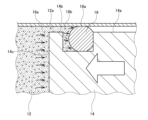
図1は、参考例に係るディスペンサーの概略構成を示す模式図である。図2は、図1のA領域の拡大図である。図1に示すプランジャーポンプ10は、筒状のコンパートメント12の内部にて、ピストン14を直線的に往復動させる。ピストン14の外周面14aに環状に形成された溝14bには、ピストン14の外周面14aとコンパートメント12の内周面12aとの間を封止するOリング16が装着されている。
FIG. 1 is a schematic diagram showing a schematic configuration of a dispenser according to a reference example. FIG. 2 is an enlarged view of area A in FIG. The
このような状態で、ピストン駆動源の駆動力によってコンパートメント12側に押し出されたピストン先端面14cやシール面16aには、ピストン駆動源によって生じる応力と同程度の圧力が働く。そのため、粒子分散液18(固形物を含む流体)をコンパートメント12に充填して計量を行う場合、液状のバインダー18aに分散された固形物の粒子18bがシール面16aに侵入し、Oリング16が損傷すると考えられる。Oリング16の損傷は、封止性能の低下を招くため、Oリング16を頻繁に交換することが必要となり、作業効率の低下を招くことになる。
In this state, the
そこで、本願発明者は、上述のOリングの損傷を招く現象を鑑み、以下の新たなディスペンサーを考案した。図3は、本実施の形態に係るディスペンサーの概略構成を示す模式図である。図4は、図3のB領域の拡大図である。 Therefore, the inventors of the present application devised the following new dispenser in view of the phenomenon that causes damage to the O-ring. FIG. 3 is a schematic diagram showing a schematic configuration of a dispenser according to this embodiment. FIG. 4 is an enlarged view of area B in FIG.
図3に示すディスペンサー20は、円柱状のピストン22と、粒子を含む液状の材料が充填される円柱状の計量室24と、計量室24に突き出すピストン22が往復動する円柱状のピストン室26と、を有する筐体28と、ピストン室26の内周面26aとピストン22との間を封止する封止部材30と、を備える。ピストン22は、計量室24の内部を往復動する。また、計量室24は、突き出したピストン22の外周面22aと計量室24の内周面24aとの間に隙間Gが形成されている。本実施の形態に係るピストン22の直径L1は、例えば1~30mmであり、好ましくは2~8mmであり、更に好ましくは3~6mmである。また、隙間Gは、2~5mmであるとよい。封止部材30は、例えば、Oリングやパッキンである。
The
このように、本実施の形態に係るディスペンサー20は、突き出したピストン22の外周面22aと計量室24の内周面24aとの間に隙間Gが形成されており、計量室24に押し出されたピストン22の先端面22bに加わる圧力P1よりも、隙間Gに加わる圧力P2を低減できる。そのため、隙間Gの先にあるピストン室26に設けられている封止部材30に加わる圧力も低くなり、封止部材30と、ピストン室26の内周面26aやピストン22との間に粒子が入りにくくなる。その結果、粒子による封止部材30やピストン22の摩耗(損耗)が低減され、部品交換や装置停止に伴うコスト上昇を抑制できる。
Thus, in the
筐体28は、計量室24とピストン室26とがつながる開口部32を有している。開口部32の内径L2は、筐体28の内径L3よりも小さい。これにより、ピストン22と計量室24の内周面24aとの間の隙間Gを大きくできる。
The
ピストン室26は、内周面26aに形成された環状の凹溝26bを有している。封止部材30は、凹溝26bに装着されたOリングである。
The
筐体28は、材料を計量室24に充填するための充填口34と、ピストン22の動きに応じて計量室24に充填されている材料が吐出される吐出口36と、を有している。充填口34は、計量室24の内周面24aに形成されている。吐出口36は、充填口34よりもピストン室26から離れた領域に形成されている。これにより、計量室24のピストン室26側の領域に材料の一部が滞留しにくくなる。
The
また、ディスペンサー20は、充填口34の開閉を行う第1のバルブ38と、吐出口36の開閉を行う第2のバルブ40と、ピストン22を往復動する駆動源42と、第1のバルブ38及び第1のバルブ38の開閉タイミング、並びに、駆動源42の駆動を制御する制御部44と、更に備えている。
The
駆動源42は、機械式、空気圧式、電磁式等の各種アクチュエータを用いることができる。アクチュエータは、ピストン22を繰り返し往復動できる機構であればよく、好ましくは、ストロークやストロークスピードを変更できる機構を備えているとよい。より具体的には、計量可変の場合はモータ駆動によるボールネジ機構が挙げられる。また、計量固定の場合はエアーシリンダー等が挙げられる。いずれの方式も、ストローク作動距離の繰り返し精度を高めることで、液剤定量吐出の吐出精度が向上します。なお、本実施の形態に係るピストン22のストロークは、例えば1~300mmである。また、ストローク回数は5回/s以下、より実用的には2回/s以下であってもよい。
Various types of actuators such as mechanical, pneumatic, and electromagnetic actuators can be used as the
図5は、計量室に材料を充填する際のディスペンサー各部の動きを説明するための模式図である。図6は、計量室から材料を吐出する際のディスペンサー各部の動きを説明するための模式図である。 FIG. 5 is a schematic diagram for explaining the movement of each part of the dispenser when filling the weighing chamber with the material. FIG. 6 is a schematic diagram for explaining the movement of each part of the dispenser when the material is discharged from the weighing chamber.
図5に示すように、制御部44は、第1のバルブ38を開き第2のバルブ40を閉じたタイミングで、計量室24からピストン22ピストンが退避する方向に駆動源42を駆動する。これにより、計量室24からピストン22が退避した部分の体積に相当する材料が計量室24に流入する。例えば、円柱状のピストン22の直径が6mm、ピストン22の退避の際のストロークが10mmの場合、π×3×3×10[mm3]=0.28mlの材料が充填口34より計量室24に流入する。
As shown in FIG. 5, the
その後、図6に示すように、第1のバルブ38を閉じ第2のバルブ40を開いたタイミングで、計量室24へピストン22が進行する方向に駆動源42を駆動する。これにより、計量室24へピストン22が進行した部分の体積に相当する材料が計量室24から流出する。例えば、円柱状のピストン22の直径が6mm、ピストン22の進行の際のストロークが10mmの場合、π×3×3×10[mm3]=0.28mlの材料が吐出口36より外部へ吐出される。このように、第1のバルブ38及び第2のバルブ40の開閉タイミングと、ピストン22の進退のタイミングとを制御することで、一定の体積の材料を繰り返し吐出することができる。計量室24の容積は、ディスペンサー20の用途や材料の種類によって適宜選択できるが、例えば、0.1~200mlの範囲であり、1.0~100mlの範囲であってもよい。
After that, as shown in FIG. 6, at the timing when the
本実施の形態に係る粒子分散液等の材料は、平均粒径が1~100μmの粒子を含み、粘度が5000~500000CPSである。例えば、半田、金ペースト、銀ペースト、銅ペースト、封止材といった電子基板製作の際に用いられるものや、食品(香辛料含有ドレッシング)、建築材セメントといった様々な粒子分散液が本実施の形態に係る材料になり得る。粒子を分散する分散溶媒(バインダー)としては、有機溶媒や生理食塩水、水等である。 A material such as a particle dispersion liquid according to the present embodiment contains particles with an average particle size of 1 to 100 μm, and has a viscosity of 5000 to 500000 CPS. For example, various particle dispersions such as solder, gold paste, silver paste, copper paste, and sealing material used in the manufacture of electronic substrates, foods (dressings containing spices), and building material cement can be used in this embodiment. It can be such a material. Dispersion solvents (binders) for dispersing the particles include organic solvents, physiological saline, water, and the like.
計量室24は、図6に示すように、材料の移動に変化をつける凹凸46が内周面24aに形成されていてもよい。これにより、ピストン22の往復動による計量室24内での材料の移動の際に、材料を撹拌する効果が得られ、材料に含まれる粒子の分散が良好な状態を維持しやすくなる。凹凸46は、例えば、環状の突起、螺旋状の突起、ランダムに配置された突起があり得る。あるいは、内周面24aが波打った形状の凹凸46であってもよい。このような凹凸46を設けられるのは、ピストン22と計量室24の内周面24aとの間に隙間Gが設けられているからである。
As shown in FIG. 6, the weighing
また、計量室24とピストン22との間に隙間Gがあることで、粒子分散液による計量室24の内周面24aやピストン22の摩耗が低減される。そのため、筐体28やピストン22を、比較的硬度の高くない材質(例えば、比較的安価なステンレス)から選択できる。また、硬度や耐摩耗性を高くするための表面コート、焼き入れ等の加工を省略することが可能となり、低コストの材料の選択肢が広がる。また、計量室24の内周面24aとピストン22との接触を考慮する必要がなくなるため、それぞれの部材に求められる加工精度が低くてもよくなり、加工コストの低減に繋がる。
In addition, since there is a gap G between the measuring
以上、本発明を上述の実施の形態を参照して説明したが、本発明は上述の実施の形態に限定されるものではなく、実施の形態の構成を適宜組み合わせたものや置換したものについても本発明に含まれるものである。また、当業者の知識に基づいて実施の形態における組合せや処理の順番を適宜組み替えることや各種の設計変更等の変形を実施の形態に対して加えることも可能であり、そのような変形が加えられた実施の形態も本発明の範囲に含まれうる。 Although the present invention has been described with reference to the above-described embodiments, the present invention is not limited to the above-described embodiments, and can be applied to any suitable combination or replacement of the configurations of the embodiments. It is included in the present invention. Further, it is also possible to appropriately rearrange the combinations and the order of processing in the embodiments based on the knowledge of a person skilled in the art, and to add modifications such as various design changes to the embodiments. Embodiments described may also fall within the scope of the present invention.
20 ディスペンサー、 22 ピストン、 22a 外周面、 22b 先端面、 24 計量室、 24a 内周面、 26 ピストン室、 26a 内周面、 26b 凹溝、 28 筐体、 30 封止部材、 32 開口部、 34 充填口、 36 吐出口、 38 第1のバルブ、 40 第2のバルブ、 42 駆動源、 44 制御部、 46 凹凸、 L1 直径、 L2 内径、 L3 内径。
20
Claims (5)
平均粒径が1~100μmの粒子を含む液状の材料が充填される柱状の計量室と、前記計量室に突き出す前記ピストンが往復動するピストン室と、を有する筐体と、
前記ピストン室の内周面と前記ピストンとの間を封止する封止部材と、を備え、
前記ピストンは、前記計量室の内部を往復動し、
前記計量室は、突き出した前記ピストンの外周面と該計量室の内周面との間に第1の隙間が形成されており、
前記筐体は、前記計量室と前記ピストン室とがつながる開口部と、前記材料を前記計量室に充填するための充填口と、前記ピストンの動きに応じて前記計量室に充填されている材料が吐出される吐出口と、を有し、
前記ピストン室は、内周面に形成された環状の凹溝を有し、かつ、前記ピストンの外周面と前記ピストン室の内周面との間に前記粒子が入り込む第2の隙間が形成されており、
前記封止部材は、前記凹溝に装着されており、
前記充填口は、前記ピストンがストロークする範囲の前記計量室の内周面に形成されており、
前記吐出口は、前記充填口よりもピストン室から離れた領域に形成されており、
前記開口部の内径は、前記計量室の内径よりも小さく、
前記ピストンは、直径が1~30mmであり、
前記第1の隙間は、2~5mmであり、
前記粒子は、金属またはセラミックスであることを特徴とするディスペンサー。 a piston;
a housing having a columnar measuring chamber filled with a liquid material containing particles with an average particle diameter of 1 to 100 μm, and a piston chamber in which the piston protruding into the measuring chamber reciprocates;
A sealing member that seals between the inner peripheral surface of the piston chamber and the piston,
The piston reciprocates inside the measuring chamber,
a first gap is formed between the protruding outer peripheral surface of the piston and the inner peripheral surface of the measuring chamber ;
The housing includes an opening connecting the measuring chamber and the piston chamber, a filling port for filling the measuring chamber with the material, and a material filled in the measuring chamber according to the movement of the piston. and an ejection port through which is ejected,
The piston chamber has an annular groove formed on its inner peripheral surface, and a second gap into which the particles enter is formed between the outer peripheral surface of the piston and the inner peripheral surface of the piston chamber. and
The sealing member is mounted in the concave groove,
The filling port is formed on the inner peripheral surface of the measuring chamber within a stroke range of the piston,
The discharge port is formed in a region farther from the piston chamber than the filling port,
The inner diameter of the opening is smaller than the inner diameter of the measuring chamber,
The piston has a diameter of 1 to 30 mm,
The first gap is 2 to 5 mm,
A dispenser , wherein the particles are metal or ceramics .
前記吐出口の開閉を行う第2のバルブと、
前記ピストンを往復動する駆動源と、
前記第1のバルブ及び前記第2のバルブの開閉タイミング、並びに、前記駆動源の駆動を制御する制御部と、更に備え、
前記制御部は、
前記第1のバルブを開き前記第2のバルブを閉じたタイミングで、前記計量室からピストンが退避する方向に駆動源を駆動し、
前記第1のバルブを閉じ前記第2のバルブを開いたタイミングで、前記計量室へピストンが進行する方向に駆動源を駆動することを特徴とする請求項1又は2に記載のディスペンサー。 a first valve that opens and closes the filling port;
a second valve that opens and closes the discharge port;
a drive source for reciprocating the piston;
a control unit that controls opening/closing timings of the first valve and the second valve, and driving of the drive source;
The control unit
driving a drive source in a direction in which the piston is retracted from the measuring chamber at the timing when the first valve is opened and the second valve is closed;
3. The dispenser according to claim 1 , wherein the driving source is driven in the direction in which the piston advances to the measuring chamber at the timing when the first valve is closed and the second valve is opened.
前記ピストンのストロークが1~300mmであることを特徴とする請求項1又は2に記載のディスペンサー。 The measuring chamber has a volume of 0.1 to 200 ml,
A dispenser according to claim 1 or 2, characterized in that the stroke of said piston is 1-300 mm.
Priority Applications (1)
| Application Number | Priority Date | Filing Date | Title |
|---|---|---|---|
| JP2022109948A JP7215790B1 (en) | 2022-07-07 | 2022-07-07 | dispenser |
Applications Claiming Priority (1)
| Application Number | Priority Date | Filing Date | Title |
|---|---|---|---|
| JP2022109948A JP7215790B1 (en) | 2022-07-07 | 2022-07-07 | dispenser |
Publications (2)
| Publication Number | Publication Date |
|---|---|
| JP7215790B1 true JP7215790B1 (en) | 2023-01-31 |
| JP2024008242A JP2024008242A (en) | 2024-01-19 |
Family
ID=85111705
Family Applications (1)
| Application Number | Title | Priority Date | Filing Date |
|---|---|---|---|
| JP2022109948A Active JP7215790B1 (en) | 2022-07-07 | 2022-07-07 | dispenser |
Country Status (1)
| Country | Link |
|---|---|
| JP (1) | JP7215790B1 (en) |
Citations (4)
| Publication number | Priority date | Publication date | Assignee | Title |
|---|---|---|---|---|
| JP2008520908A (en) | 2004-11-23 | 2008-06-19 | エンテグリース,インコーポレイテッド | System and method for a variable home position dispensing system |
| WO2008129591A1 (en) | 2007-04-10 | 2008-10-30 | Kikuo Tamura | Biliquid circulation agitation apparatus |
| JP2016044574A (en) | 2014-08-20 | 2016-04-04 | 麻生フオームクリート株式会社 | Force feeding pump |
| JP2022092208A (en) | 2020-12-10 | 2022-06-22 | 株式会社ニコン | Pipe member, mixing and stirring device and modeling device |
Family Cites Families (1)
| Publication number | Priority date | Publication date | Assignee | Title |
|---|---|---|---|---|
| JPS5692417A (en) * | 1979-12-26 | 1981-07-27 | Toshiba Corp | Measuring and discharging device |
-
2022
- 2022-07-07 JP JP2022109948A patent/JP7215790B1/en active Active
Patent Citations (4)
| Publication number | Priority date | Publication date | Assignee | Title |
|---|---|---|---|---|
| JP2008520908A (en) | 2004-11-23 | 2008-06-19 | エンテグリース,インコーポレイテッド | System and method for a variable home position dispensing system |
| WO2008129591A1 (en) | 2007-04-10 | 2008-10-30 | Kikuo Tamura | Biliquid circulation agitation apparatus |
| JP2016044574A (en) | 2014-08-20 | 2016-04-04 | 麻生フオームクリート株式会社 | Force feeding pump |
| JP2022092208A (en) | 2020-12-10 | 2022-06-22 | 株式会社ニコン | Pipe member, mixing and stirring device and modeling device |
Also Published As
| Publication number | Publication date |
|---|---|
| JP2024008242A (en) | 2024-01-19 |
Similar Documents
| Publication | Publication Date | Title |
|---|---|---|
| US6565333B2 (en) | Fluid discharge apparatus and fluid discharge method | |
| US9440781B2 (en) | Droplet discharge device and method | |
| CN102935416B (en) | Based on the glue dispensing valve of Piezoelectric Ceramic and flexible magnifying arm | |
| US8757511B2 (en) | Viscous non-contact jetting method and apparatus | |
| JP5925311B2 (en) | Dosing system and dosing method | |
| KR102012303B1 (en) | Liquid material discharge apparatus and method | |
| KR102559677B1 (en) | Piezoelectric jetting system and method | |
| JP6127114B2 (en) | Piezoelectric pneumatic valve driven dispensing pump and solution dispensing method using the same | |
| JP3648882B2 (en) | Fluid supply apparatus and method | |
| JP7215790B1 (en) | dispenser | |
| JP2001246298A (en) | Fluid ejection device and fluid ejection method | |
| KR102467695B1 (en) | Application nozzle head and liquid application apparatus having it | |
| US5024587A (en) | Valveless pump | |
| CN102580889A (en) | Dispensing device and dispensing system | |
| JP2004084592A (en) | Fluid control device and fluid control method | |
| US6398081B2 (en) | Volumetric pump | |
| JP4065450B2 (en) | Fluid ejection device | |
| JP4077624B2 (en) | Fluid ejection device and fluid ejection method | |
| JP3747764B2 (en) | Fluid supply apparatus and fluid supply method | |
| JP3685009B2 (en) | Fluid supply apparatus and fluid supply method | |
| JP3858585B2 (en) | Fluid supply method | |
| CN219711737U (en) | Electric plunger pump and spraying machine for granular materials | |
| JP6031018B2 (en) | Reciprocating motion switching device and reciprocating actuator | |
| CN217029194U (en) | Cam driving mechanism for four-plunger metering pump | |
| CN214600083U (en) | Accurate glue spraying device |
Legal Events
| Date | Code | Title | Description |
|---|---|---|---|
| A621 | Written request for application examination |
Free format text: JAPANESE INTERMEDIATE CODE: A621 Effective date: 20220719 |
|
| A871 | Explanation of circumstances concerning accelerated examination |
Free format text: JAPANESE INTERMEDIATE CODE: A871 Effective date: 20220719 |
|
| A131 | Notification of reasons for refusal |
Free format text: JAPANESE INTERMEDIATE CODE: A131 Effective date: 20220913 |
|
| A521 | Request for written amendment filed |
Free format text: JAPANESE INTERMEDIATE CODE: A523 Effective date: 20221107 |
|
| TRDD | Decision of grant or rejection written | ||
| A01 | Written decision to grant a patent or to grant a registration (utility model) |
Free format text: JAPANESE INTERMEDIATE CODE: A01 Effective date: 20230110 |
|
| A61 | First payment of annual fees (during grant procedure) |
Free format text: JAPANESE INTERMEDIATE CODE: A61 Effective date: 20230112 |
|
| R150 | Certificate of patent or registration of utility model |
Ref document number: 7215790 Country of ref document: JP Free format text: JAPANESE INTERMEDIATE CODE: R150 |
|
| R250 | Receipt of annual fees |
Free format text: JAPANESE INTERMEDIATE CODE: R250 |