JP7207006B2 - Network management device, method and program - Google Patents
Network management device, method and program Download PDFInfo
- Publication number
- JP7207006B2 JP7207006B2 JP2019031788A JP2019031788A JP7207006B2 JP 7207006 B2 JP7207006 B2 JP 7207006B2 JP 2019031788 A JP2019031788 A JP 2019031788A JP 2019031788 A JP2019031788 A JP 2019031788A JP 7207006 B2 JP7207006 B2 JP 7207006B2
- Authority
- JP
- Japan
- Prior art keywords
- entity
- layer
- tpe
- spec
- logical
- Prior art date
- Legal status (The legal status is an assumption and is not a legal conclusion. Google has not performed a legal analysis and makes no representation as to the accuracy of the status listed.)
- Active
Links
Images


Classifications
-
- H—ELECTRICITY
- H04—ELECTRIC COMMUNICATION TECHNIQUE
- H04L—TRANSMISSION OF DIGITAL INFORMATION, e.g. TELEGRAPHIC COMMUNICATION
- H04L41/00—Arrangements for maintenance, administration or management of data switching networks, e.g. of packet switching networks
- H04L41/08—Configuration management of networks or network elements
- H04L41/0889—Techniques to speed-up the configuration process
-
- H—ELECTRICITY
- H04—ELECTRIC COMMUNICATION TECHNIQUE
- H04L—TRANSMISSION OF DIGITAL INFORMATION, e.g. TELEGRAPHIC COMMUNICATION
- H04L45/00—Routing or path finding of packets in data switching networks
- H04L45/24—Multipath
Landscapes
- Engineering & Computer Science (AREA)
- Computer Networks & Wireless Communication (AREA)
- Signal Processing (AREA)
- Data Exchanges In Wide-Area Networks (AREA)
Description
本発明の実施形態は、ネットワーク管理装置、方法及びプログラムに関する。 The embodiments of the present invention relate to a network management device, method and program.
ネットワーク(NW)を構成するネットワーク装置を管理し、ユーザからのオーダに応じて装置への設定作業を実施するネットワークオペレーション業務において、複数の装置への煩雑な設定作業を自動化するためのネットワーク管理システムが用いられている。ネットワーク管理システムは管理対象のネットワーク/装置に合わせて管理情報を保持するための、ネットワーク情報管理機能を有している。 A network management system for automating complicated setting tasks for multiple devices in network operation tasks that manage network devices that make up a network (NW) and perform device setting work according to orders from users. is used. The network management system has a network information management function for holding management information according to the networks/devices to be managed.
しかし、従来のネットワーク管理システムは、ネットワーク/装置に特化した管理機能を持つため、ネットワーク装置の機種、ネットワーク方式の変更を行なうたびに、ネットワーク管理システムを開発することが必要であった。 However, since conventional network management systems have management functions specialized for networks/equipment, it was necessary to develop a new network management system each time a change was made to the type of network equipment or network method.
そこで、管理対象ネットワークの機種を変更したり、通信方式を変更したりする場合に、管理対象ネットワーク毎にネットワーク管理システムを開発し直す必要がないシステムアーキテクチャがある(例えば非特許文献1を参照)。 Therefore, there is a system architecture that eliminates the need to redevelop a network management system for each managed network when changing the model of the managed network or changing the communication method (see, for example, Non-Patent Document 1). .
非特許文献1に記載されたアーキテクチャは、管理対象ネットワークに依存しない汎用的なデータの保持を可能とする仕組みを持っており、管理対象に合わせて複数のネットワーク管理情報(エンティティ(実体))を生成する。しかし、異なるネットワーク方式(通信プロトコル)を使ったネットワークを管理する場合、又は多数の装置を管理する場合は、エンティティの生成量が多くなり、ネットワークオペレータ(以下、単にオペレータと称することがある)の作業負荷が大きくなってしまう。 The architecture described in Non-Patent Document 1 has a mechanism that enables storage of general-purpose data that does not depend on the network to be managed. Generate. However, when managing networks using different network methods (communication protocols) or when managing a large number of devices, the number of entities generated increases, and network operators (hereinafter sometimes simply referred to as operators) Work load increases.
また、管理対象ネットワーク上に、ネットワーク利用ユーザの利用要望を満たす多数の経路が存在する場合、どの経路を使用するのかをオペレータが選択する必要があり、その結果作業負荷がさらに大きくなる。 In addition, if there are many routes on the network to be managed that meet the needs of network users, the operator must select which route to use, resulting in an even greater workload.
この発明は、上記事情に着目してなされたもので、その目的とするところは、ネットワークの設定に要する作業負荷を軽減することができるようにしたネットワーク管理装置、方法およびプログラムを提供することにある。 SUMMARY OF THE INVENTION The present invention has been made in view of the above circumstances, and its object is to provide a network management apparatus, method, and program capable of reducing the work load required for setting up a network. be.
上記目的を達成するために、この発明のネットワーク管理装置の一態様は、プロセッサと、ネットワークの情報オブジェクトの実体を表す第1のエンティティを記憶する第1の記憶部と、前記情報オブジェクトの仕様を記憶する第2の記憶部とを有し、前記プロセッサは、前記第1の記憶部に記憶された第1のエンティティに基づいて、前記ネットワークの所定の始点と終点との間の物理レイヤの経路を選択する経路選択処理を行ない、前記第2の記憶部に記憶された仕様に基づいて、前記経路選択処理により選択された物理レイヤの経路に対応する、論理レイヤの第2のエンティティを生成するエンティティ生成処理を行なうように構成され、前記第2の記憶部は、前記物理レイヤおよび最下層の論理レイヤとの間の関係性、および前記最下層を含む複数の層の論理レイヤ間の関係性を定義する情報を、前記情報オブジェクトの仕様として記憶し、前記プロセッサは、前記エンティティ生成処理として、前記経路選択処理により選択された経路における物理レイヤの上位レイヤとして定義される、最下層の論理レイヤの仕様を前記第2の記憶部から取得し、前記最下層の論理レイヤの上位レイヤとして定義される各層の論理レイヤの仕様を前記第2の記憶部から取得し、前記経路選択処理より選択された物理レイヤの経路に対応する論理レイヤの第2のエンティティを生成するときに、前記取得された仕様に基づいて、同じ層又は1つ下位の層のレイヤにおける第3のエンティティとの関係性を保持し、前記保持される関係性に基づいて、前記経路選択処理より選択された物理レイヤの経路に対応する、各層の論理レイヤの第2のエンティティを生成する、ようにしたものである。 In order to achieve the above object, one aspect of the network management apparatus of the present invention provides a processor, a first storage section storing a first entity representing the substance of an information object of a network, and a specification of the information object. and a second storage unit for storing physical layer paths between predetermined start points and end points of the network based on the first entity stored in the first storage unit. and generating a second entity of the logical layer corresponding to the path of the physical layer selected by the route selection process based on the specifications stored in the second storage unit configured to perform entity generation processing, wherein the second storage unit stores the relationship between the physical layer and the lowest logical layer, and the relationship between a plurality of logical layers including the lowest layer; is stored as the specification of the information object, and the processor, as the entity generation process, is the lowest logical layer defined as the upper layer of the physical layer in the route selected by the route selection process from the second storage unit, acquires from the second storage unit the specifications of each logical layer defined as an upper layer of the lowest logical layer, and selects from the route selection process When generating the second entity of the logical layer corresponding to the path of the physical layer obtained, based on the acquired specification, the relationship with the third entity in the same layer or one lower layer and generating a second entity of the logical layer of each layer corresponding to the physical layer route selected by the route selection process based on the held relationship .
本発明のネットワーク管理方法の一態様は、プロセッサと、ネットワークの情報オブジェクトの実体を表す第1のエンティティを記憶する第1の記憶装置と、前記情報オブジェクトの仕様を記憶する第2の記憶装置とを具備するネットワーク管理装置が行なうネットワーク管理方法であって、前記プロセッサは、前記第1の記憶装置に記憶された第1のエンティティに基づいて、前記ネットワークの所定の始点と終点との間の物理レイヤの経路を選択する経路選択処理を行ない、前記プロセッサは、前記第2の記憶装置に記憶された仕様に基づいて、前記経路選択処理により選択された物理レイヤの経路に対応する、論理レイヤの第2のエンティティを生成するエンティティ生成処理を行ない、前記第2の記憶装置は、前記物理レイヤおよび最下層の論理レイヤとの間の関係性、および前記最下層を含む複数の層の論理レイヤ間の関係性を定義する情報を、前記情報オブジェクトの仕様として記憶し、前記プロセッサは、前記エンティティ生成処理として、前記経路選択処理により選択された経路における物理レイヤの上位レイヤとして定義される、最下層の論理レイヤの仕様を前記第2の記憶装置から取得し、前記最下層の論理レイヤの上位レイヤとして定義される各層の論理レイヤの仕様を前記第2の記憶装置から取得し、前記経路選択処理より選択された物理レイヤの経路に対応する論理レイヤの第2のエンティティを生成するときに、前記取得された仕様に基づいて、同じ層又は1つ下位の層のレイヤにおける第3のエンティティとの関係性を保持し、前記保持される関係性に基づいて、前記経路選択処理より選択された物理レイヤの経路に対応する、各層の論理レイヤの第2のエンティティを生成する、ようにしたものである。 One aspect of the network management method of the present invention includes a processor, a first storage device storing a first entity representing the substance of an information object of a network, and a second storage device storing specifications of the information object. , wherein the processor performs physical management between a predetermined start point and end point of the network based on a first entity stored in the first storage device. A route selection process for selecting a layer route is performed, and the processor selects a logical layer route corresponding to the physical layer route selected by the route selection process based on the specifications stored in the second storage device. An entity generation process for generating a second entity is performed , and the second storage device stores the relationship between the physical layer and the lowest logical layer, and the logical layers of a plurality of layers including the lowest layer. Information defining relationships between layers is stored as the specification of the information object, and the processor is defined as a layer above the physical layer in the route selected by the route selection process as the entity generation process. Acquiring specifications of the lowest logical layer from the second storage device, acquiring specifications of the logical layers of each layer defined as upper layers of the lowest logical layer from the second storage device, and acquiring the path When generating a second entity of the logical layer corresponding to the path of the physical layer selected by the selection process, based on the obtained specifications, a third entity in the same layer or a layer one layer below. and generating a second entity of the logical layer of each layer corresponding to the route of the physical layer selected by the route selection process based on the held relationship It is.
本発明のネットワーク管理処理プログラムの一態様は、一態様におけるネットワーク管理装置の前記各処理として前記プロセッサを機能させるものである。 One aspect of the network management processing program of the present invention causes the processor to function as each of the processes of the network management device in one aspect.
この発明のネットワーク管理装置の一態様によれば、エンティティに基づいて、ネットワークの所定の始点と終点との間の物理レイヤの経路を選択する経路選択処理を行ない、情報オブジェクトの仕様に基づいて、選択された物理レイヤの経路に対応する、論理レイヤのエンティティを生成するので、論理レイヤのエンティティの設定にかかる負荷を軽減することができる。 According to one aspect of the network management device of the present invention, route selection processing is performed to select a physical layer route between a predetermined start point and end point of the network based on the entity, and based on the specification of the information object, Since the logical layer entity corresponding to the selected physical layer path is generated, the load for setting the logical layer entity can be reduced.
この発明のネットワーク管理装置の一態様によれば、物理レイヤおよび最下層の論理レイヤとの間の関係性、および最下層を含む複数の層の論理レイヤの間の関係性がそれぞれ定義され、この関係性に基づいて、経路における物理レイヤに対応する各層の論理レイヤ仕様を取得するので、エンティティの生成対象である各層の論理レイヤの仕様を適切に取得することができる。 According to one aspect of the network management device of the present invention, the relationship between the physical layer and the lowest logical layer, and the relationship between a plurality of logical layers including the lowest layer are defined, Since the logical layer specifications of each layer corresponding to the physical layer in the path are acquired based on the relationship, the logical layer specifications of each layer for which entities are to be generated can be appropriately acquired.
この発明のネットワーク管理装置の一態様によれば、物理レイヤの経路に対応する論理レイヤのエンティティを生成するときに、同じ層又は1つ下位の層のレイヤにおけるエンティティとの関係性を保持し、この関係性に基づいて、物理レイヤの経路に対応する、各層の論理レイヤのエンティティを生成するので、物理レイヤに対応する、各層の論理レイヤのエンティティを適切に生成することができる。 According to one aspect of the network management apparatus of the present invention, when generating a logical layer entity corresponding to a physical layer path, a relationship with an entity in the same layer or a layer one layer below is maintained, Based on this relationship, the logical layer entity of each layer corresponding to the path of the physical layer is generated, so the logical layer entity of each layer corresponding to the physical layer can be generated appropriately.
すなわち、本発明の各態様によれば、ネットワークの設定に要する作業負荷を軽減することが可能になる。 That is, according to each aspect of the present invention, it is possible to reduce the work load required for setting the network.
以下、図面を参照しながら、この発明に係わる一実施形態を説明する。
図1は、ネットワーク管理システムの一例を示す図である。
ここで、従来技術における課題について説明する。
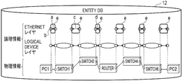
図1に示すように、ネットワーク管理システム(ネットワーク管理装置)による管理対象ネットワークが、6台のEthernet(登録商標) Switch(以下、単にSwitchと称することがある)であるSwitch1、Switch2、Switch3、Switch4、Switch5、Switch6と、1台のIP(インターネットプロトコル) Router(以下、単にRouterと称することがある)であるRouterで構成されているものとする。
An embodiment according to the present invention will be described below with reference to the drawings.
FIG. 1 is a diagram showing an example of a network management system.
Here, problems in the conventional technology will be described.
As shown in FIG. 1, the networks managed by the network management system (network management device) are six Ethernet (registered trademark) Switches (hereinafter sometimes simply referred to as Switches) Switch1, Switch2, Switch3, and Switch4. , Switch5, Switch6, and one IP (Internet Protocol) Router (hereinafter sometimes simply referred to as Router).
この管理対象ネットワークでは、2台のパーソナルコンピュータ(PC)であるPC1とPC2のうちPC1に対してSwitch2、Switch3の一端が通信可能に並列接続され、Switch2、Switch3の他端に対してRouterの一端が通信可能に接続され、Routerの他端に対しSwitch4、Switch5の一端が通信可能に並列接続され、Switch4、Switch5の他端に対してSwitch6の一端が通信可能に接続され、Switch6の他端にPC2が通信可能に接続される。 In this managed network, PC1 and PC2, which are two personal computers (PCs), are connected in parallel to one end of Switch2 and Switch3 for communication, and one end of Router is connected to the other end of Switch2 and Switch3. are communicably connected, one end of Switch4 and Switch5 are connected in parallel to the other end of Router, one end of Switch6 is communicably connected to the other end of Switch4 and Switch5, and the other end of Switch6 is PC2 is communicably connected.
このネットワーク上にPC1とPC2とを通信可能に接続して利用したいユーザからの要望に対して、オペレータは、図1で示される機器で形成可能な下記の4通りの通信経路の中から1つの経路を選択して、この選択した経路に対応するネットワーク管理情報(エンティティ)をネットワーク管理システムに対して生成する作業を実施する。 In response to a request from a user who wants to connect and use PC1 and PC2 communicably on this network, the operator selects one of the following four communication paths that can be formed by the equipment shown in FIG. Performs the task of selecting a route and generating network management information (entities) corresponding to the selected route to the network management system.
経路(1):PC1→Switch1→Switch2→Router→Switch4→Switch6→PC2
経路(2):PC1→Switch1→Switch3→Router→Switch4→Switch6→PC2
経路(3):PC1→Switch1→Switch2→Router→Switch5→Switch6→PC2
経路(4):PC1→Switch1→Switch3→Router→Switch5→Switch6→PC2
上記のオペレータによる経路の選択、およびエンティティの生成の作業に、オペレータに負荷がかかることが課題である。
Route (1): PC1→Switch1→Switch2→Router→Switch4→Switch6→PC2
Route (2): PC1→Switch1→Switch3→Router→Switch4→Switch6→PC2
Route (3): PC1→Switch1→Switch2→Router→Switch5→Switch6→PC2
Route (4): PC1→Switch1→Switch3→Router→Switch5→Switch6→PC2
The problem is that the operator is burdened with the route selection and entity creation work described above.
ネットワーク管理システムで管理するエンティティとして、以下の種類が存在する。
物理レイヤの構成は、PD(Physical Device), PP(Physical Port), PL(Physical Link)を含むEntity(情報オブジェクト)を適用し、論理レイヤの構成はTL(Topological Link), NFD(Network Forwarding Domain),TPE(Termination Point Encapsulation), FRE(Forwarding Relationship Encapsulation)でなるEntityを適用する。FRE は、NC(Network Connection),LC(Link Connect), XC(Cross(X) Connect)を含む。このような適用により、物理レイヤおよび論理レイヤの構成を統一した形式で保持することができる。
The following types of entities are managed by the network management system.
The configuration of the physical layer applies entities (information objects) including PD (Physical Device), PP (Physical Port), PL (Physical Link), and the configuration of the logical layer is TL (Topological Link), NFD (Network Forwarding Domain). ), TPE (Termination Point Encapsulation), and FRE (Forwarding Relationship Encapsulation). FRE includes NC (Network Connection), LC (Link Connect), and XC (Cross(X) Connect). Such adaptation allows the configuration of the physical and logical layers to be kept in a uniform format.
ここで、NW構成(物理、論理レイヤ)のモデリングについて説明する。図2は、ネットワーク管理装置に適用されるネットワーク構成のモデリングの一例を表形式で示す図である。
図2に示すように、物理レイヤにおけるEntity名は、PD, PP, PLに区分される。それぞれのEntity名における「Entity名:意味」の対応は下記のとおりである。
・PD(Physical Device):装置
・PP(Physical Port):装置が持つ通信ポート
・PL(Physical Link):装置間の接続ケーブル
Here, modeling of NW configuration (physical and logical layers) will be described. FIG. 2 is a table showing an example of network configuration modeling applied to a network management device.
As shown in FIG. 2, Entity names in the physical layer are classified into PD, PP, and PL. The correspondence of "Entity name: Meaning" for each Entity name is as follows.
- PD (Physical Device): Device - PP (Physical Port): Communication port of the device - PL (Physical Link): Connection cable between devices
図2に示すように、論理レイヤにおけるEntity名は、TL, NFD, TPE, FRE(NC, LC, XC)に区分される。それぞれのEntity名における「Entity名:意味」の対応は下記のとおりである。
・TL(Topological Link):装置間の接続性
・NFD(Network Forwarding Domain):装置内の転送可能な範囲
・TPE(Termination Point Encapsulation):通信の終端点
・FRE(Forwarding Relationship Encapsulation)のNC(Network Connection):TPE間のLC、XCによって形成されるEnd-Endの接続性
・FREのLC(Link Connect):TPEで終端される装置間の接続性
・FREのXC(Cross Connect):TPEで終端される装置内の接続性
As shown in FIG. 2, entity names in the logical layer are classified into TL, NFD, TPE, and FRE (NC, LC, XC). The correspondence of "Entity name: Meaning" for each Entity name is as follows.
・TL (Topological Link): Connectivity between devices ・NFD (Network Forwarding Domain): Transferable range within the device ・TPE (Termination Point Encapsulation): Termination point of communication ・NC (Network of FRE (Forwarding Relationship Encapsulation) Connection): End-End connectivity formed by LC and XC between TPEs ・FRE LC (Link Connect): Connectivity between devices terminated by TPE ・FRE XC (Cross Connect): Termination at TPE connectivity within the device
図3は、ネットワーク管理システムに対する対象ネットワークの情報の生成の一例を示す図である。
図3に示すように、オペレータによる選択により(図3中のa)管理対象ネットワークに上記の経路(1)「PC1→Switch1→Switch2→Router→Switch4→Switch6→PC2」を割り当てた(図3中のb)ネットワーク管理情報をネットワーク管理システムで保持する場合、下記のようにエンティティの総数は90個であるので、この数に応じた合計90回の生成指示(図3中のc)をオペレータが実施する必要がある。
(物理情報:物理レイヤ)PD:9個、PP:20個、PL:5個
(論理情報のIPレイヤ、Ethernetレイヤ、およびLogical Deviceレイヤ(LDレイヤと呼ぶこともある):論理レイヤ)TL:6個、NFD:6個、TPE:28個、FRE(NC):3個、FRE(LC):8個、FRE(XC):5個
このように経路選択とエンティティ作成のための負荷が膨大になることがある。論理レイヤは、IPレイヤ、Ethernetレイヤ、Logical Deviceレイヤの順で連なる複数の層でなり、IPレイヤは論理レイヤ最上層に対応し、Logical Deviceレイヤは論理レイヤ最下層に対応する。論理レイヤ最下層は、物理レイヤの上位レイヤとして定義される。
FIG. 3 is a diagram illustrating an example of generation of target network information for the network management system.
As shown in FIG. 3, the above route (1) "PC1→Switch1→Switch2→Router→Switch4→Switch6→PC2" was assigned to the network to be managed (a in FIG. 3) by selection by the operator (in FIG. 3). b) When the network management information is held in the network management system, the total number of entities is 90 as shown below. Need to implement.
(Physical information: physical layer) PD: 9, PP: 20, PL: 5 (Logical information IP layer, Ethernet layer, and Logical Device layer (also called LD layer): Logical layer) TL: 6, NFD: 6, TPE: 28, FRE(NC): 3, FRE(LC): 8, FRE(XC): 5 In this way, the load for route selection and entity creation is enormous. can be The logical layer is composed of a plurality of layers in sequence of IP layer, Ethernet layer, and Logical Device layer. The IP layer corresponds to the top layer of the logical layer, and the Logical Device layer corresponds to the bottom layer of the logical layer. The bottom layer of the logical layer is defined as the layer above the physical layer.
図4は、本発明の一実施形態に係るネットワーク管理システムの適用例を示す図である。
図4に示した例では、本発明の一実施形態では、ネットワーク管理システム10は、経路選択部11、Entity DB(データベース)12、エンティティ補完部13、Spec(Specification(仕様)) DB14を有する。これらに係る処理の詳細は後述する。
FIG. 4 is a diagram showing an application example of the network management system according to one embodiment of the present invention.
In the example shown in FIG. 4, the
経路選択部11は、管理対象ネットワークにおける経路を選択する。Entity DB12は、情報オブジェクトであるエンティティに係る情報を格納する。エンティティ補完部13は、Entity DB12に格納されるエンティティを補完して生成する。Spec DB14は、情報オブジェクトの仕様に情報を格納する。
ネットワーク管理システム10の経路選択部11、Entity DB12、エンティティ補完部13、Spec DB14の機能は、プログラムを実行するCPU(Central Processing Unit)等のプロセッサ、キーボードなどの入力装置、ディスプレイなどの出力装置、およびRAM(Random Access Memory)、ROM(Read Only Memory)等の記憶媒体を含むコンピュータなどを用いて実現される。各部の動作については後述する。
The
The functions of the
なお、ネットワーク管理システム10はハードウェアで構成することもできるが、後述するフローチャートに示された手順を備えるプログラムを、媒体もしくは通信回線を介して周知のコンピュータにインストールして、このコンピュータとEntity DB12、Spec DB14との組み合わせ、又はEntity DB12、Spec DB14を有するコンピュータなどによっても実現可能である。
The
ネットワーク管理システム10は、管理対象ネットワークに係るオペレータの作業を軽減し、少ない作業で経路選択後のエンティティの生成・保持を可能とする。
オペレータは、(1)「物理ネットワークに対応する物理エンティティの生成指示」と、(2)「ユーザ要望に基づき開通させるネットワークの始点と終点の指定」のための操作をそれぞれ行なうこととする。経路の選択と、不足するエンティティの補完とは、経路選択部11、エンティティ補完部13により自動的にそれぞれ実行される。
本発明の一実施形態により、オペレータによる、エンティティ生成に係る作業を減らすことが可能となる。
The
The operator performs operations for (1) "instructing generation of a physical entity corresponding to a physical network" and (2) "designating the start point and end point of the network to be opened based on the user's request". Selection of a route and supplementation of missing entities are automatically performed by the
An embodiment of the present invention makes it possible to reduce the operator's work related to entity generation.
図5は、本発明の一実施形態に係るネットワーク管理システムにより生成されるエンティティの一例を説明する図である。
例えば、図3に示した例では、計90個のエンティティの生成に係る作業が必要である。これに対し、図5に示した例では、本発明の一実施形態により、同じ条件のネットワークにおいて、論理情報のIPレイヤ、Ethernetレイヤ、およびLogical Deviceレイヤの上記計56個のエンティティはエンティティ補完部13によって生成される。よって、オペレータによる、これらのエンティティの生成作業が不要となるため、オペレータは、は物理情報における上記34個のエンティティの生成に係る操作を行えばよい。
FIG. 5 is a diagram illustrating an example of entities generated by the network management system according to one embodiment of the present invention.
For example, in the example shown in FIG. 3, work related to generation of a total of 90 entities is required. On the other hand, in the example shown in FIG. 5, according to an embodiment of the present invention, in a network under the same conditions, the above 56 entities in the IP layer, Ethernet layer, and Logical Device layer of logical information are replaced by the entity complementing unit. 13. Therefore, since the operator does not need to generate these entities, the operator only has to perform operations related to the generation of the above 34 entities in the physical information.
次に、本発明の一実施形態による実施手順の全体の例を説明する。
(事前準備)
図6および図7は、本発明の一実施形態に係るネットワーク管理システムの実施手順の一例を示す図である。
(1) オペレータは、入力操作により、ネットワーク管理システム10のSpec DB14に対して、ネットワークを規定する仕様(Specification)を登録することができる。
An example of an overall implementation procedure according to one embodiment of the present invention will now be described.
(Advance preparation)
6 and 7 are diagrams showing an example of a procedure for implementing a network management system according to one embodiment of the present invention.
(1) The operator can register the specifications that define the network in the
(2) オペレータは、入力操作により、ネットワーク管理システム10において、物理レイヤのエンティティ(物理エンティティと称することもある)を生成してEntity DB12に格納することができる。
(2) The operator can generate a physical layer entity (also referred to as a physical entity) in the
(ネットワーク経路選択・ネットワークエンティティ生成)
(1) オペレータは、ユーザからのリクエストに基づき、開通するネットワークの始点・終点情報(Physical Port/PP)を経路選択部11に入力する。図7に示した例では、始点をPC1として、終点をPC2とすることができる。
(Network route selection/network entity generation)
(1) The operator inputs the start point/end point information (Physical Port/PP) of the network to be opened to the
(2) 経路選択部11は、始点情報のPPから物理情報上のPhysical Link(PL)、Physical Device(PD)の接続関係をたどり、終点情報のPPに至るまでの経路を選択する。
(3) 経路選択部11は、選択した経路に対応するPP/PL/PDをエンティティ補完部13に入力する。
(4) エンティティ補完部13は、Spec DB14からSpecを取得する。
(5) エンティティ補完部13は、取得したSpecを用いて、上記入力されたPP/PL/PDに対応する論理レイヤのエンティティ(論理エンティティと称することもある)を生成する。
(2) The
(3) The
(4) The
(5) The
次に、本発明の一実施形態による実施手順の詳細の例を説明する。
(経路選択部)
図8は、本発明の一実施形態に係るネットワーク管理システムの経路選択部による処理手順の一例を示す図である。
経路選択部11は、物理エンティティ同士の接続関係を辿り、始点から終点まで、ひと筆書きで辿り着ける経路を選択し、選択結果として物理エンティティ(PP/PL/PD)をEntity DB12から取得する。
An example of details of an implementation procedure according to one embodiment of the present invention will now be described.
(Route selection part)
FIG. 8 is a diagram showing an example of a processing procedure by the route selection unit of the network management system according to one embodiment of the present invention.
The
また、経路選択のポリシーは、最少ホップ数、帯域、遅延量などを考慮した経路探索アルゴリズムを適用できるものとする。アルゴリズム自体は既知のアルゴリズムを用いることができる。 In addition, it is assumed that the route selection policy can apply a route search algorithm that considers the minimum number of hops, bandwidth, amount of delay, and the like. A known algorithm can be used as the algorithm itself.
次に、エンティティ補完部13によるSpec取得に係る処理手順の詳細について説明する。図9は、本発明の一実施形態に係るネットワーク管理システムのエンティティ補完部によるSpec取得に係る処理手順の一例を示すフローチャートである。
(概要)
エンティティ補完部13は、経路選択部11から入力されたPP/PL/PDに対応する論理レイヤのSpecをSpec DB14から取得する。エンティティ補完部13は、取得したSpecの上位・下位の関係性も合わせて内部メモリに保持する。
Next, the details of the processing procedure related to Spec acquisition by the
(overview)
The
(詳細)
(1) エンティティ補完部13は、PPのSpecの上位レイヤとして定義されているTPEのSpecをSpec DB14から取得する(S11)。
(2) エンティティ補完部13は、(1)で取得したTPE Specのさらに上位レイヤとして定義されているTPE Specがある場合、そのTPE SpecもSpec DB14から繰り返し取得する(S12)。
(detail)
(1) The
(2) If there is a TPE Spec defined as a higher layer than the TPE Spec acquired in (1), the
(3) エンティティ補完部13は、PLのSpecの上位レイヤとして定義されているTLのSpecをSpec DB14から取得する(S13)。
(4) エンティティ補完部13は、(3)で取得したTL Specの上位レイヤとして定義されているFRE(LC)のSpecをSpec DB14から取得する(S14)。
(3) The
(4) The
(5) エンティティ補完部13は、PDのSpecの上位レイヤとして定義されているNFDのSpecをSpec DB14から取得する(S15)。
(6) エンティティ補完部13は、(5)で取得したNFD Specの上位レイヤとして定義されているFRE(XC)のSpecをSpec DB14から取得する(S16)。
(5) The
(6) The
(7) エンティティ補完部13は、(4)で取得したFRE(LC)のSpecと(6)で取得したFRE(XC)のSpecの上位に定義されているFRE(NC)のSpecをSpec DB14から取得する(S17)。
(7) The
(8) エンティティ補完部13は、(7)で取得したFRE(NC)のさらに上位レイヤとして定義されているFRE(LC)がある場合、そのFRE(LC)SpecをSpec DB14から取得し、さらに上記(7)を実行する(S18)。(7)で取得したFRE(NC)のさらに上位レイヤとして定義されているFRE(LC)が無くなったらエンティティ補完部13は、Spec取得に係る処理を終了する。
(8) If there is an FRE (LC) defined as a higher layer than the FRE (NC) acquired in (7), the
次に、エンティティ補完部13による論理エンティティ生成に係る処理手順の詳細について説明する。図10は、本発明の一実施形態に係るネットワーク管理システムのエンティティ補完部によるSpec取得に係る処理の概要を示す図である。
(概要)
エンティティ補完部13は、上記取得したSpecに対応するエンティティ(TPE/TL/NFD/FRE(LC)/FRE(XC)/FRE(NC))を生成する。
エンティティ補完部13は、生成するエンティティが関連する下位のエンティティに対する関連性(関係性)を内部メモリに保持する。
Next, the details of the processing procedure related to logical entity generation by the
(overview)
The
The
図11は、本発明の一実施形態に係るネットワーク管理システムのエンティティ補完部による論理エンティティ生成に係る処理手順の一例を示すフローチャートである。
(詳細)
(1) エンティティ補完部13は、Logical DeviceレイヤのTPEエンティティを生成する。以下、TPEと単に称することがある。生成する際には、エンティティ補完部13は、物理エンティティPPへの関連性を保持する(S21)。
FIG. 11 is a flow chart showing an example of a processing procedure relating to logical entity generation by the entity complementing unit of the network management system according to one embodiment of the present invention.
(detail)
(1) The
(2) エンティティ補完部13は、Logical DeviceレイヤのTLエンティティを生成する。以下、TLと単に称することがある。生成する際には、エンティティ補完部13は、Logical DeviceレイヤのTPEへの関連性を保持する(S22)。
(2) The
(3) エンティティ補完部13は、Logical DeviceレイヤのNFDエンティティを生成する。以下、NFDと単に称することがある。生成する際には、エンティティ補完部13は、Logical DeviceレイヤのTPEへの関連性を保持する(S23)。
(3) The
エンティティ補完部13は、下記の(4)、(5)、(6)、(7)について、下位のレイヤから順に実施する。全てのレイヤについて実施したら、エンティティ補完部13は、(4)、(5)、(6)、(7)を終了する。
The
(4) エンティティ補完部13は、論理レイヤのTPEを生成する。生成する際には、エンティティ補完部13は、下位の論理レイヤのTPEへの関連性を保持する(S24)。
(5) エンティティ補完部13は、論理レイヤのFRE(LC)エンティティを生成する。以下、FRE(LC)と単に称することがある。生成する際には、エンティティ補完部13は、該当レイヤのTPEへの関連性を保持する(S25)。
(4) The
(5) The
(6) エンティティ補完部13は、論理レイヤのFRE(XC)エンティティを生成する。以下、FRE(XC)と単に称することがある。生成する際には、エンティティ補完部13は、該当レイヤのTPEへの関連性を保持する(S26)。
(7) エンティティ補完部13は、論理レイヤのFRE(NC)エンティティを生成する。以下、FRE(NC)と単に称することがある。生成する際には、エンティティ補完部13は、該当レイヤのTPEへの関連性を保持する(S27)。
(6) The
(7) The
以下、図3に示したネットワークと同じネットワークを管理対象ネットワークとする業務に本発明の一実施形態を適用した例を示す。
事前準備として、オペレータにより下記のSpecがSpec DB14に登録される。図12、図13は、登録されるSpecの表記、意味の一例を表形式で示す図である。
登録されるSpecの種類であるPP、PL、PD、TPE、TL、NFD、FRE(LC)、FRE(XC)、FRE(NC)について、「登録するSpecの表記:意味」の対応は下記の通りである。
An example in which an embodiment of the present invention is applied to a business whose managed network is the same network as the network shown in FIG. 3 will be described below.
As a preparation, the following Spec is registered in the
Regarding the registered Spec types PP, PL, PD, TPE, TL, NFD, FRE(LC), FRE(XC), FRE(NC), the correspondence of "Notation of Spec to be registered: Meaning" is as follows. Street.
(PP)
PP_PC:PCのPP
PP_SW:SwitchのPP
PP_R:RouterのPP
(PL)
PL_PC-SW:PC~Switch間のPL
PL_SW-SW:Switch~Switch間のPL
PL_SW-R:Switch~Router間のPL
(PD)
PD_PC:PCのPD
PD_SW:SwitchのPD
PD_R:RouterのPD
(PP)
PP_PC: PC PP
PP_SW: Switch's PP
PP_R: Router's PP
(PL)
PL_PC-SW: PL between PC and Switch
PL_SW-SW: PL between Switch and Switch
PL_SW-R: PL between Switch and Router
(PD)
PD_PC: PC PD
PD_SW: Switch PD
PD_R: Router's PD
(TPE)
TPE_PC_LD:PCのLogical DeviceレイヤのTPE
TPE_PC_E:PCのEthernetレイヤのTPE
TPE_PC_IP:PCのIPレイヤのTPE
TPE_SW_LD:SwitchのLogical DeviceレイヤのTPE
TPE_SW_E:SwitchのEthernetレイヤのTPE
TPE_R_LD:RouterのLogical DeviceレイヤのTPE
TPE_R_E:RouterのEthernetレイヤのTPE
TPE_R_IP:RouterのIPレイヤのTPE
(TL)
TL_PC-SW:PC~Switch間のTL
TL_SW-SW:Switch~Switch間のTL
TL_SW-R:Switch~Router間のTL
(NFD)
NFD_SW:SwitchのNFD
NFD_R:RouterのNFD
(TPE)
TPE_PC_LD: TPE of Logical Device layer of PC
TPE_PC_E: TPE for Ethernet layer of PC
TPE_PC_IP: PC IP layer TPE
TPE_SW_LD: Switch Logical Device layer TPE
TPE_SW_E: Switch Ethernet layer TPE
TPE_R_LD: Router's Logical Device layer TPE
TPE_R_E: Router's Ethernet layer TPE
TPE_R_IP: Router's IP layer TPE
(TL)
TL_PC-SW: TL between PC and Switch
TL_SW-SW: TL between Switch and Switch
TL_SW-R: TL between Switch and Router
(NFD)
NFD_SW: Switch's NFD
NFD_R: Router's NFD
(FRE(LC))
FRELC_PC-SW_E:PC~Switch間のEthernetレイヤのFRE(LC)
FRELC_SW-SW_E:Switch~Switch間のEthernetレイヤのFRE(LC)
FRELC_SW-R_E:Switch~Router間のEthernetレイヤのFRE(LC)
FRELC_PC-R_IP:PC~Router間のIPレイヤのFRE(LC)
(FRE(XC))
FREXC_SW_E:SwitchのEthernetレイヤのFRE(XC)
FREXC_R_IP:RouterのIPレイヤのFRE(XC)
(FRE(NC))
FRENC_PC-R_E:PC~Router間のEthernetレイヤのFRE(NC)
FRENC_PC-PC_IP:PC~PC間のIPレイヤのFRE(NC)
(FRE(LC))
FRELC_PC-SW_E: Ethernet layer FRE (LC) between PC and Switch
FRELC_SW-SW_E: Ethernet layer FRE (LC) between Switches
FRELC_SW-R_E: Ethernet layer FRE (LC) between Switch and Router
FRELC_PC-R_IP: IP layer FRE (LC) between PC and Router
(FRE(XC))
FREXC_SW_E: Switch Ethernet layer FRE (XC)
FREXC_R_IP: Router's IP layer FRE (XC)
(FRE(NC))
FRENC_PC-R_E: Ethernet layer FRE (NC) between PC and Router
FRENC_PC-PC_IP: IP layer FRE (NC) between PC and PC
図14は、登録されたSpecにおける関係性の一例を表形式で示す図である。
登録されたSpecは、図14に示す上下レイヤの関係性を持つものとする。
IPレイヤ、Ethernetレイヤ、Logical Deviceレイヤ、物理レイヤにおけるSpecの関係性は下記の(1)~(13)の通りである。下記(1)~(13)のうち、(1)は経路の始点に、(13)は経路の終点にそれぞれ対応する。
FIG. 14 is a diagram showing an example of relationships in registered Specs in tabular form.
It is assumed that the registered Spec has the upper and lower layer relationships shown in FIG. 14 .
The relationships of Specs in the IP layer, Ethernet layer, Logical Device layer, and physical layer are as shown in (1) to (13) below. Of the following (1) to (13), (1) corresponds to the starting point of the route, and (13) corresponds to the ending point of the route.
(1)
(IPレイヤ)、(Ethernetレイヤ)、(Logical Deviceレイヤ):なし
(物理レイヤ)PD_PC
(1)
(IP layer), (Ethernet layer), (Logical Device layer): None (Physical layer) PD_PC
(2)
(IPレイヤ)TPE_PC_IP
(Ethernetレイヤ)TPE_PC_E
(Logical Deviceレイヤ)TPE_PC_LD
(物理レイヤ)PP_PC
(2)
(IP layer) TPE_PC_IP
(Ethernet layer) TPE_PC_E
(Logical Device Layer) TPE_PC_LD
(physical layer) PP_PC
(3)
(IPレイヤ(上位))FRENC_PC-PC_IP
(IPレイヤ(下位))FRELC_PC-R_IP
(Ethernetレイヤ(上位))FRENC_PC-R_E
(Ethernetレイヤ(下位))FRELC_PC-SW_E
(Logical Deviceレイヤ)TL_PC-SW
(物理レイヤ)PL_PC-SW
(3)
(IP layer (upper)) FRENC_PC-PC_IP
(IP layer (lower)) FRELC_PC-R_IP
(Ethernet layer (upper)) FRENC_PC-R_E
(Ethernet layer (lower)) FRELC_PC-SW_E
(Logical Device Layer) TL_PC-SW
(Physical layer) PL_PC-SW
(4)
(IPレイヤ(上位、下位))(Ethernetレイヤ(上位)):上記(3)と同じ
(Ethernetレイヤ(下位))TPE_SW_E
(Logical Deviceレイヤ)TPE_SW_LD
(物理レイヤ)PP_SW
(4)
(IP layer (upper, lower)) (Ethernet layer (upper)): Same as (3) above (Ethernet layer (lower)) TPE_SW_E
(Logical Device Layer) TPE_SW_LD
(physical layer) PP_SW
(5)
(IPレイヤ(上位、下位))(Ethernetレイヤ(上位)):上記(3)と同じ
(Ethernetレイヤ(下位))FREXC_SW_E
(Logical Deviceレイヤ)NFD_SW
(物理レイヤ)PD_SW
(6)
上記(4)と同じ
(5)
(IP layer (upper, lower)) (Ethernet layer (upper)): Same as (3) above (Ethernet layer (lower)) FREXC_SW_E
(Logical Device Layer) NFD_SW
(physical layer) PD_SW
(6)
Same as (4) above
(7)
(IPレイヤ(上位、下位))(Ethernetレイヤ(上位)):上記(3)と同じ
(Ethernetレイヤ(下位))FRELC_SW-SW_E
(Logical Deviceレイヤ)TL_SW-SW
(物理レイヤ)PL_SW-SW
(7)
(IP layer (upper, lower)) (Ethernet layer (upper)): Same as (3) above (Ethernet layer (lower)) FRELC_SW-SW_E
(Logical Device Layer) TL_SW-SW
(physical layer) PL_SW-SW
(8)
上記(4)と同じ
(9)
上記(5)と同じ
(10)
上記(4)と同じ
(8)
Same as (4) above (9)
Same as (5) above (10)
Same as (4) above
(11)
(IPレイヤ(上位、下位))(Ethernetレイヤ(上位)):上記(3)と同じ
(Ethernetレイヤ(下位))FRELC_SW-R_E
(Logical Deviceレイヤ)TL_SW-R
(物理レイヤ)PL_SW-R
(11)
(IP layer (upper, lower)) (Ethernet layer (upper)): Same as (3) above (Ethernet layer (lower)) FRELC_SW-R_E
(Logical Device Layer) TL_SW-R
(physical layer) PL_SW-R
(12)
(IPレイヤ(上位))FRENC_PC-PC_IP(上記(3)と同じ)
(IPレイヤ(下位))TPE_R_IP
(Ethernetレイヤ)TPE_R_E
(Logical Deviceレイヤ)TPE_R_LD
(物理レイヤ)PP_R
(12)
(IP layer (upper)) FRENC_PC-PC_IP (same as (3) above)
(IP layer (lower)) TPE_R_IP
(Ethernet layer) TPE_R_E
(Logical Device Layer) TPE_R_LD
(physical layer) PP_R
(13)
(IPレイヤ(上位))FRENC_PC-PC_IP(上記(3)と同じ)
(IPレイヤ(下位))FREXC_R_IP
(Ethernetレイヤ):なし
(Logical Deviceレイヤ)NFD_R
(物理レイヤ)PD_R
(13)
(IP layer (upper)) FRENC_PC-PC_IP (same as (3) above)
(IP layer (lower)) FREXC_R_IP
(Ethernet layer): None (Logical Device layer) NFD_R
(physical layer) PD_R
図15、図16、図17は、物理エンティティの登録の一例を示す図である。
上記登録された物理レイヤのSpecを用いて、オペレータにより物理エンティティがEntity DB12に登録される。
15, 16, and 17 are diagrams showing an example of physical entity registration.
The physical entity is registered in the
図15では、物理レイヤのSpecを用いて登録される物理エンティティ情報の対応関係を示す。
図15に示した物理エンティティは図16に示した形式で表記されるものとする。また、それぞれのエンティティ間の接続関係を相互に持つものとする。
図17に示すように物理エンティティが事前準備としてEntity DB12に登録されたものとする。Specとの対応関係は図15にならうものとする。
FIG. 15 shows the correspondence relationship of physical entity information registered using Spec of the physical layer.
Assume that the physical entities shown in FIG. 15 are represented in the format shown in FIG. It is also assumed that each entity has a mutual connection relationship.
Assume that the physical entity is registered in the
図15に示す、利用するSpecと登録される物理エンティティとの関係、および図16で対応する表記を下記の(a)~(e)に示す。
(a)
(利用するSpec)PD_PC
(登録される物理エンティティ)PC1
(物理エンティティの表記)「PD_PC」Specを用いた「PC1」エンティティ
The relationship between Specs to be used and physical entities to be registered, shown in FIG. 15, and corresponding notations in FIG. 16 are shown in (a) to (e) below.
(a)
(Spec to use) PD_PC
(Registered Physical Entity) PC1
(physical entity notation) "PC1" entity using "PD_PC" Spec
(b)
(利用するSpec)PP_PC
(登録される物理エンティティ)PC1_P1
(物理エンティティの表記)「PP_PC」Specを用いた「PC1_P1」エンティティ
(b)
(Spec to use) PP_PC
(Registered physical entity) PC1_P1
(Physical entity notation) "PC1_P1" entity using "PP_PC" Spec
(c)
(利用するSpec)PL_PC-SW
(登録される物理エンティティ)PC1-SW1_PL
(物理エンティティの表記)「PL_PC-SW」Specを用いた「PC1-SW1_PL」エンティティ
(c)
(Spec to use) PL_PC-SW
(Registered Physical Entity) PC1-SW1_PL
(Physical entity notation) "PC1-SW1_PL" entity using "PL_PC-SW" Spec
(d)
(利用するSpec)PP_SW
(登録される物理エンティティ)Switch1_P1
(物理エンティティの表記)「PP_SW」Specを用いた「Switch1_P1」エンティティ
(d)
(Spec to use) PP_SW
(Registered Physical Entity) Switch1_P1
(Physical entity notation) "Switch1_P1" entity using "PP_SW" Spec
(e)
(利用するSpec)PD_SW
(登録される物理エンティティ)Switch1
(物理エンティティの表記)「PD_SW」Specを用いた「Switch1」エンティティ
(e)
(Spec to use) PD_SW
(Registered Physical Entity) Switch1
(Physical Entity Notation) 'Switch1' Entity with 'PD_SW' Spec
次に始点・終点情報の指定について説明する。図18は、始点・終点情報の指定の一例を説明する図である。
オペレータが、管理対象ネットワークについてEntity DB12に格納される物理エンティティの「PC1」を経路の始点と指定し、物理エンティティの「PC2」を経路の終点と指定し、経路選択部11は、それぞれのエンティティを始点・終点と記録する。
Next, the designation of start point/end point information will be described. FIG. 18 is a diagram illustrating an example of designation of start point/end point information.
The operator designates the physical entity "PC1" stored in the
次に経路選択について説明する。
経路選択部11は、物理エンティティ同士の接続関係をたどり、始点から終点までひと筆書きでたどり着ける経路を選択し、選択結果として物理エンティティ(PP/PL/PD)をEntity DB12から取得する。
ここでは、上記の経路「PC1→Switch1→Switch2→Router→Switch4→Switch6→PC2」の順番の経路が選択されたものとする。ここでPP、PLの記載は省略する。
Next, route selection will be explained.
The
Here, it is assumed that the above route "PC1->Switch1->Switch2->Router->Switch4->Switch6->PC2" is selected in this order. Description of PP and PL is omitted here.
次に経路入力について説明する。図19は、経路入力の一例を示す図である。
経路選択部11は、取得した経路に対応する物理エンティティ(PP/PL/PD)をエンティティ補完部13に入力する。
Next, route input will be described. FIG. 19 is a diagram showing an example of route input.
The
次にSpec取得について説明する。
エンティティ補完部13は、入力された物理エンティティを元に、Spec DB14から論理エンティティのSpecを下記の(1)~(8)のように取得する。
(1) エンティティ補完部13は、PPのSpecの上位レイヤとして定義されているTPEのSpecをSpec DB14から取得する。
具体的には、物理エンティティ「PC1_P1」はSpec「PP_PC」に基づいているため、エンティティ補完部13は、このSpec「PP_PC」の上位に定義された「TPE_PC_LD」をSpec DB14から取得する。同様に、エンティティ補完部13は、Switch1/2/4/6の各PPのSpec「PP_SW」の上位である「TPE_SW_LD」と、RouterのPPのSpec「PP_R」の上位であるSpec「TPE_R_LD」とをSpec DB14からそれぞれ取得する。
Next, Spec acquisition will be explained.
Based on the input physical entity, the
(1) The
Specifically, since the physical entity “PC1_P1” is based on the Spec “PP_PC”, the
(2) エンティティ補完部13は、(1)で取得したTPE Specのさらに上位レイヤとして定義されているTPE Specがある場合、このTPE SpecもSpec DB14から繰り返し取得する。
具体的には、エンティティ補完部13は、(1)で取得した、Logical Deviceレイヤの上位の全てのSpecをSpec DB14に繰り返しアクセスすることで取得する。
取得対象は「TPE_PC_E」「TPE_PC_IP」「TPE_SW_E」「TPE_R_E」「TPE_R_IP」である。
(2) If there is a TPE Spec defined as a higher layer than the TPE Spec acquired in (1), the
Specifically, the
The acquisition targets are "TPE_PC_E", "TPE_PC_IP", "TPE_SW_E", "TPE_R_E", and "TPE_R_IP".
(3) エンティティ補完部13は、PLのSpecの上位レイヤとして定義されているTLのSpecをSpec DB14から取得する。
具体的には、物理エンティティ「PC1-SW1_PL」はSpec「PL_PC-SW」に基づいているため、エンティティ補完部13は、この「PL_PC-SW」Specの上位に定義された「TL_PC-SW」をSpec DB14から取得する。同様に、エンティティ補完部13は、Switch~Switch間、Switch~Router間の物理エンティティPLのSpecの上位に定義された「TL_SW-SW」「TL_SW-R」をSpec DB14から取得する。
(3) The
Specifically, since the physical entity "PC1-SW1_PL" is based on the Spec "PL_PC-SW", the
(4) エンティティ補完部13は、(3)で取得したTL Specの上位レイヤとして定義されているFRE(LC)のSpecをSpec DB14から取得する。
具体的には、エンティティ補完部13は、(3)で取得した、Logical Deviceレイヤの上位の全てのSpecをSpec DB14に繰り返しアクセスすることで取得する。
取得対象は「FRELC_PC-SW_E」「FRELC_SW-SW_E」「FRELC_SW-R_E」である。
(4) The
Specifically, the
The acquisition targets are "FRELC_PC-SW_E", "FRELC_SW-SW_E", and "FRELC_SW-R_E".
(5) エンティティ補完部13は、PDのSpecの上位レイヤとして定義されているNFDのSpecをSpec DB14から取得する。
具体的には、物理エンティティ「Switch1」はSpec「PD_SW」に基づいているため、エンティティ補完部13は、このSpec「PD_SW」の上位に定義された「NFD_SW」をSpec DB14から取得する。同様に、エンティティ補完部13は、RouterのSpec「PD_R」の上位であるSpec「NFD_R」をSpec DB14から取得する。
(6) エンティティ補完部13は、(5)で取得したNFD Specの上位レイヤとして定義されているFRE(XC)のSpecをSpec DB14から取得する。
具体的には、エンティティ補完部13は、(5)で取得したLogical Deviceレイヤの上位の全てのSpecをSpec DB14から繰り返しアクセスすることで取得する。
取得対象は「FREXC_SW_E」「FREXC_R_IP」である。
(5) The
Specifically, since the physical entity “Switch1” is based on the Spec “PD_SW”, the
(6) The
Specifically, the
The acquisition targets are "FREXC_SW_E" and "FREXC_R_IP".
(7) エンティティ補完部13は、(4で)取得したFRE(LC)と(6)で取得したFRE(XC)のSpecの上位に定義されているFRE(NC)のSpecをSpec DB14から取得する。
具体的には、エンティティ補完部13は、取得したSpecのうち、EthernetレイヤのSpecである「FRELC_PC-SW_E」「FRELC_SW-SW_E」「FREXC_SW_E」を組み合わせた「FRENC_PC-R_E」をSpec DB14から取得する。
(8) エンティティ補完部13は、(7)で取得したFRE(NC)のさらに上位レイヤとして定義されているFRE(LC)がある場合、このFRE(LC) SpecをSpec DB14から取得し、さらに上記(4)を実行する。FRE(NC)の上位に定義されているFRE(LC)がなくなったら終了する。
(7) The
Specifically, the
(8) If there is an FRE (LC) defined as a higher layer than the FRE (NC) obtained in (7), the
具体的には、エンティティ補完部13は、(7)で取得したSpec「FRENC_PC-R_E」の上位に定義された「FRELC_PC-R_IP」をSpec DB14から取得する。
さらに、エンティティ補完部13は、取得した「FRELC_PC-R_IP」と(6)で取得した「FREXC_R_IP」とを組み合わせて「FRENC_PC-PC_IP」をSpec DB14から取得する。
以上により、上位に定義されたSpecが存在しないため、Spec取得にかかる処理が終了する。
Specifically, the
Furthermore, the
As described above, since there is no Spec defined at a higher level, the process for obtaining Spec ends.
次に、エンティティ生成について説明する。
エンティティ補完部13は、上記取得したSpec群に対して、論理レイヤのエンティティを下位のレイヤから順に下記の(1)~(7)のように生成してEntity DB12へ格納する。
(1) エンティティ補完部13は、Logical DeviceレイヤのTPEを生成する。この生成の際には、エンティティ補完部13は、物理エンティティPPへの関連性を保持する。
Next, entity generation will be described.
The
(1) The
図20、図21は、Logical DeviceレイヤのTPEの生成の一例を示す図である。具体的には、エンティティ補完部13は、取得した、Logical DeviceレイヤのSpecに対し、図20に示すようにTPEエンティティを生成する。生成の一部は図示を省略する。各TPEエンティティは、図20の最下行に示すPPエンティティへの関連性を持つ。最終的に、エンティティ補完部13は、図21に示す12個のTPEエンティティを生成する。
20 and 21 are diagrams showing an example of generation of TPE of the Logical Device layer. Specifically, the
図20に示す、「利用するSpec」、「生成するLogical DeviceレイヤのTPEエンティティ」、「関連性を持つ物理エンティティ」の対応の例は下記の(a)~(d)のとおりである。
(a)
(利用するSpec)TPE_PC_LD
(生成するLogical DeviceレイヤのTPEエンティティ)PC1_P1_LD_TPE
(関連性を持つ物理エンティティ)PC1_P1
Examples of the correspondence between "Spec to be used", "TPE entity of Logical Device layer to be generated", and "Related physical entity" shown in FIG. 20 are as follows (a) to (d).
(a)
(Spec to use) TPE_PC_LD
(TPE entity of Logical Device layer to be generated) PC1_P1_LD_TPE
(physical entity with association) PC1_P1
(b)
(利用するSpec)TPE_SW_LD
(生成するLogical DeviceレイヤのTPEエンティティ)Switch1_P1_LD_TPE
(関連性を持つ物理エンティティ)Switch1_P1
(b)
(Spec to use) TPE_SW_LD
(TPE entity of Logical Device layer to be generated) Switch1_P1_LD_TPE
(Physical entity with association) Switch1_P1
(c)
(利用するSpec)TPE_SW_LD
(生成するLogical DeviceレイヤのTPEエンティティ)Switch1_P2_LD_TPE
(関連性を持つ物理エンティティ)Switch1_P2
(c)
(Spec to use) TPE_SW_LD
(TPE entity of Logical Device layer to be generated) Switch1_P2_LD_TPE
(physical entity with association) Switch1_P2
(d)
(利用するSpec)TPE_R_LD
(生成するLogical DeviceレイヤのTPEエンティティ)Router_P1_LD_TPE
(関連性を持つ物理エンティティ)Router_P1
(d)
(Spec to use) TPE_R_LD
(TPE entity of Logical Device layer to be generated) Router_P1_LD_TPE
(Physical entity with association) Router_P1
図21中のa、b、c、d、e、fの意味は下記のとおりである。
(a)「TPE_PC_LD」Specを用いた「PC1_P1_LD_TPE」エンティティ
(b)「PC1_P1_LD_TPE」エンティティは「PC1_P1」エンティティへの関連性を持つ
(c)「TPE_SW_LD」Specを用いた「Swtich1_P1_LD_TPE」エンティティ
(d)「TPE_SW_LD」Specを用いた「Swtich1_P2_LD_TPE」エンティティ
(e)「TPE_R_LD」Specを用いた「Router_P1_LD_TPE」エンティティ
(f)本処理プロセスにより生成されるTPEエンティティを示す
The meanings of a, b, c, d, e, and f in FIG. 21 are as follows.
(a) "PC1_P1_LD_TPE" entity using "TPE_PC_LD" Spec (b) "PC1_P1_LD_TPE" entity has a relationship to "PC1_P1" entity (c) "Swtich1_P1_LD_TPE" entity using "TPE_SW_LD" Spec (d) ""Swtich1_P2_LD_TPE" entity using TPE_SW_LD" Spec (e) "Router_P1_LD_TPE" entity using "TPE_R_LD" Spec (f) Indicates the TPE entity generated by this processing process
(2) エンティティ補完部13は、Logical DeviceレイヤのTLを生成する。この生成の際には、エンティティ補完部13は、Logical DeviceレイヤのTPEへの関連性を保持する。
図22、図23は、Logical DeviceレイヤのTLの生成の一例を示す図である。具体的には、エンティティ補完部13は、取得したLogical DeviceレイヤのSpecに対し、図22に示すようにTLエンティティを生成する。生成の一部は図示を省略する。各TLエンティティは、図22の最下行に示す、Logical DeviceレイヤのTPEエンティティへの関連性を持つ。最終的に、エンティティ補完部13は、図23に示す6個のTLエンティティを生成する。
(2) The
22 and 23 are diagrams showing an example of generation of TL of the Logical Device layer. Specifically, the
図23に示す、「利用するSpec」、「生成するLogical DeviceレイヤのTLエンティティ」、「関連性を持つLogical DeviceレイヤのTPEエンティティ」の対応の例は下記の(a)~(c)のとおりである。
(a)
(利用するSpec)TL_PC-SW
(生成するLogical DeviceレイヤのTLエンティティ)PC1-Switch1_TL
(関連性を持つLogical DeviceレイヤのTPEエンティティ)PC1_P1_LD_TPE、Switch1_P1_LD_TPE
Correspondence examples of "Spec to be used", "TL entity of Logical Device layer to be generated", and "TPE entity of Logical Device layer having relationship" shown in Fig. 23 are shown in (a) to (c) below. is.
(a)
(Spec to use) TL_PC-SW
(TL entity of Logical Device layer to be generated) PC1-Switch1_TL
(Logical Device layer TPE entities with associations) PC1_P1_LD_TPE, Switch1_P1_LD_TPE
(b)
(利用するSpec)TL_SW-SW
(生成するLogical DeviceレイヤのTLエンティティ)Switch1-Switch2_TL
(関連性を持つLogical DeviceレイヤのTPEエンティティ)Switch1_P2_LD_TPE、Switch2_P1_LD_TPE
(b)
(Spec to use) TL_SW-SW
(TL entity of Logical Device layer to generate) Switch1-Switch2_TL
(Logical Device layer TPE entities with association) Switch1_P2_LD_TPE, Switch2_P1_LD_TPE
(c)
(利用するSpec)TL_SW-R
(生成するLogical DeviceレイヤのTLエンティティ)Switch2-Router_TL
(関連性を持つLogical DeviceレイヤのTPEエンティティ)Switch2_P2_LD_TPE、Router_P1_LD_TPE
(c)
(Spec to use) TL_SW-R
(TL entity of Logical Device layer to generate) Switch2-Router_TL
(Logical Device layer TPE entities with associations) Switch2_P2_LD_TPE, Router_P1_LD_TPE
図23中のa、b、c、d、eの意味は下記のとおりである。
(a)「TPE_PC-SW」Specを用いた「PC1-Switch1_TL」エンティティ
(b)「PC1-Switch1_TL」エンティティは「PC1_P1_LD_TPE」「Switch1_P1_LD_TPE」エンティティへの関連性を持つ
(c)「TL_SW-SW」Specを用いた「Switch1-Switch2_TL」エンティティ
(d)「TL_SW-R」Specを用いた「Switch2-Router_TL」エンティティ
(e)本処理プロセスにより生成されるTLエンティティを示す
The meanings of a, b, c, d, and e in FIG. 23 are as follows.
(a) 'PC1-Switch1_TL' entity using 'TPE_PC-SW' Spec (b) 'PC1-Switch1_TL' entity has relationships to 'PC1_P1_LD_TPE' and 'Switch1_P1_LD_TPE' entities (c) 'TL_SW-SW' Spec (d) "Switch2-Router_TL" entity using "TL_SW-R" Spec (e) Indicates the TL entity generated by this processing process
(3) エンティティ補完部13は、Logical DeviceレイヤのNFDを生成する。この生成の際には、エンティティ補完部13は、Logical DeviceレイヤのTPEへの関連性を保持する。
図24、図25は、Logical DeviceレイヤのNFDの生成の一例を示す図である。具体的には、エンティティ補完部13は、取得したLogical DeviceレイヤのSpecに対し、図24に示すようにNFDエンティティを生成する。生成の一部は図示を省略する。各NFDエンティティは、図24の最下行に示す、Logical DeviceレイヤのTPEエンティティへの関連性を持つ。最終的に、エンティティ補完部13は、図25に示す5個のNFDエンティティを生成する。
(3) The
24 and 25 are diagrams showing an example of NFD generation of the Logical Device layer. Specifically, the
図24に示す、「利用するSpec」、「生成するLogical DeviceレイヤのNFDエンティティ」、「関連性を持つLogical DeviceレイヤのTPEエンティティ」の対応の例は下記の(a)、(b)、(c)のとおりである。
(a)
(利用するSpec)NFD_SW
(生成するLogical DeviceレイヤのNFDエンティティ)Switch1_NFD
(関連性を持つLogical DeviceレイヤのTPEエンティティ)Switch1_P1_LD_TPE、Switch1_P2_LD_TPE
Correspondence examples of "Spec to be used", "NFD entity of Logical Device layer to be generated", and "TPE entity of Logical Device layer having relationship" shown in FIG. c).
(a)
(Spec to use) NFD_SW
(NFD entity of Logical Device layer to generate) Switch1_NFD
(Logical Device layer TPE entities with association) Switch1_P1_LD_TPE, Switch1_P2_LD_TPE
(b)
(利用するSpec)NFD_SW
(生成するLogical DeviceレイヤのNFDエンティティ)Switch2_NFD
(関連性を持つLogical DeviceレイヤのTPEエンティティ)Switch2_P1_LD_TPE、Switch2_P2_LD_TPE
(b)
(Spec to use) NFD_SW
(NFD entity of Logical Device layer to generate) Switch2_NFD
(Logical Device layer TPE entities with association) Switch2_P1_LD_TPE, Switch2_P2_LD_TPE
(c)
(利用するSpec)NFD_R
(生成するLogical DeviceレイヤのNFDエンティティ)Router_NFD
(関連性を持つLogical DeviceレイヤのTPEエンティティ)Router_P1_LD_TPE、Router_P2_LD_TPE
(c)
(Spec to use) NFD_R
(NFD entity of Logical Device layer to generate) Router_NFD
(Logical Device layer TPE entities with association) Router_P1_LD_TPE, Router_P2_LD_TPE
図25中のa、b、c、d、eの意味は下記のとおりである。
(a)「NFD_SW」Specを用いた「Switch1_NFD」エンティティ
(b)「Switch1_NFD」エンティティは「Switch1_P1_LD_TPE」「Switch1_P2_LD_TPE」エンティティへの関連性を持つ
(c)「NFD_SW」Specを用いた「Switch2_NFD」エンティティ
(d)「NFD_R」Specを用いた「Router_NFD」エンティティ
(e)本処理プロセスにより生成されるNFDエンティティを示す
The meanings of a, b, c, d, and e in FIG. 25 are as follows.
(a) 'Switch1_NFD' entity using 'NFD_SW' Spec (b) 'Switch1_NFD' entity has relationships to 'Switch1_P1_LD_TPE' and 'Switch1_P2_LD_TPE' entities (c) 'Switch2_NFD' entity using 'NFD_SW' Spec ( d) 'Router_NFD' entity using 'NFD_R' Spec (e) Indicates the NFD entity generated by this processing process
(4) エンティティ補完部13は、論理レイヤのTPEを生成する。この生成の際には、下位の論理レイヤのTPEへの関連性を保持する。
図26、図27は、論理レイヤのTPEの生成の一例を示す図である。具体的には、エンティティ補完部13は、Logical Deviceレイヤの上位のEthernetレイヤのSpecに対し、図26に示すTPEエンティティを生成する。生成の一部は図示を省略する。各TPEエンティティは、図26の最下行に示す、下位のLogical DeviceレイヤのTPEエンティティへの関連性を持つ。最終的に、エンティティ補完部13は、図27に示す12個のTPEエンティティを生成する。
(4) The
26 and 27 are diagrams showing an example of generation of the TPE of the logical layer. Specifically, the
図26に示す、「利用するSpec」、「生成するEthernetレイヤのTPEエンティティ」、「関連性を持つLogical DeviceレイヤのTPEエンティティ」の対応の例は下記の(a)、(b)、(c)、(d)のとおりである。
(a)
(利用するSpec)PC1_P1_E_TPE
(生成するEthernetレイヤのTPEエンティティ)PC1_P1_E_TPE
(関連性を持つLogical DeviceレイヤのTPEエンティティ)PC1_P1_LD_TPE
Examples of the correspondence between "Spec to be used", "TPE entity of Ethernet layer to be generated", and "TPE entity of Logical Device layer having relationship" shown in FIG. ) and (d).
(a)
(Spec to use) PC1_P1_E_TPE
(Generating Ethernet layer TPE entity) PC1_P1_E_TPE
(Logical Device layer TPE entity with association) PC1_P1_LD_TPE
(b)
(利用するSpec)TPE_SW_E
(生成するEthernetレイヤのTPEエンティティ)Switch1_P1_E_TPE
(関連性を持つLogical DeviceレイヤのTPEエンティティ)Switch1_P1_LD_TPE
(b)
(Spec to use) TPE_SW_E
(Generating Ethernet layer TPE entity) Switch1_P1_E_TPE
(Logical Device layer TPE entity with association) Switch1_P1_LD_TPE
(c)
(利用するSpec)TPE_SW_E
(生成するEthernetレイヤのTPEエンティティ)Switch1_P2_E_TPE
(関連性を持つLogical DeviceレイヤのTPEエンティティ)Switch1_P2_LD_TPE
(c)
(Spec to use) TPE_SW_E
(Generating Ethernet layer TPE entity) Switch1_P2_E_TPE
(Logical Device layer TPE entity with association) Switch1_P2_LD_TPE
(d)
(利用するSpec)TPE_R_E
(生成するEthernetレイヤのTPEエンティティ)Router_P1_E_TPE
(関連性を持つLogical DeviceレイヤのTPEエンティティ)Router_P1_LD_TPE
(d)
(Spec to use) TPE_R_E
(Generating Ethernet layer TPE entity) Router_P1_E_TPE
(Logical Device layer TPE entity with association) Router_P1_LD_TPE
図27中のa、b、c、d、e、fの意味は下記のとおりである。
(a)「TPE_PC_E」Specを用いた「PC1_P1_E_TPE」エンティティ
(b)「PC1_P1_E_TPE」エンティティは「PC1_P1_LD_TPE」エンティティへの関連性を持つ
(c)「TPE_SW_E」Specを用いた「Swtich1_P1_E_TPE」エンティティ
(d)「TPE_SW_E」Specを用いた「Swtich1_P2_E_TPE」エンティティ
(e)「TPE_R_E」Specを用いた「Router_P1_E_TPE」エンティティ
(f)本処理プロセスにより生成されるTPEエンティティを示す
The meanings of a, b, c, d, e, and f in FIG. 27 are as follows.
(a) "PC1_P1_E_TPE" entity using "TPE_PC_E" Spec (b) "PC1_P1_E_TPE" entity has a relationship to "PC1_P1_LD_TPE" entity (c) "Swtich1_P1_E_TPE" entity using "TPE_SW_E" Spec (d) ""Swtich1_P2_E_TPE" entity using TPE_SW_E" Spec (e) "Router_P1_E_TPE" entity using "TPE_R_E" Spec (f) Indicates the TPE entity generated by this processing process
(5) エンティティ補完部13は、論理レイヤのFRE(LC)を生成する。この生成の際には、エンティティ補完部13は、該当レイヤのTPEへの関連性を保持する。
図28、図29は、論理レイヤのFRE(LC)の生成の一例を示す図である。具体的には、エンティティ補完部13は、Logical Deviceレイヤの上位のEthernetレイヤのSpecに対し、図28に示すFRE(LC)エンティティを生成する。生成の一部の図示は省略する。各FRE(LC)エンティティは、図28の最下行に示すEthernetレイヤのTPEエンティティへの関連性を持つ。最終的に、エンティティ補完部13は、図29に示す6個のFRE(LC)エンティティを生成する。
(5) The
28 and 29 are diagrams showing an example of generation of FRE (LC) of the logical layer. Specifically, the
図28に示す、「利用するSpec」、「生成するEthernetレイヤのFRE(LC)エンティティ」、「関連性を持つEthernetレイヤのTPEエンティティ」の対応の例は下記の(a)、(b)、(c)のとおりである。
(a)
(利用するSpec)FRELC_PC-SW_E
(生成するEthernetレイヤのFRE(LC)エンティティ)PC1-Switch1_E_FRELC
(関連性を持つEthernetレイヤのTPEエンティティ)PC1_P1_E_TPE、Switch1_P1_E_TPE
Shown in FIG. 28, examples of the correspondence between "Spec to be used", "FRE (LC) entity of Ethernet layer to be generated", and "TPE entity of Ethernet layer having relationship" are shown in the following (a), (b), (c).
(a)
(Spec to use) FRELC_PC-SW_E
(Generating Ethernet layer FRE (LC) entity) PC1-Switch1_E_FRELC
(Ethernet layer TPE entities with association) PC1_P1_E_TPE, Switch1_P1_E_TPE
(b)
(利用するSpec)FRELC_SW-SW_E
(生成するEthernetレイヤのFRE(LC)エンティティ)Switch1-Switch2_E_FRELC
(関連性を持つEthernetレイヤのTPEエンティティ)Switch1_P2_E_TPE、Switch2_P1_E_TPE
(b)
(Spec to use) FRELC_SW-SW_E
(Generating Ethernet layer FRE (LC) entity) Switch1-Switch2_E_FRELC
(Ethernet layer TPE entities with association) Switch1_P2_E_TPE, Switch2_P1_E_TPE
(c)
(利用するSpec)FRELC_SW-R_E
(生成するEthernetレイヤのFRE(LC)エンティティ)Switch2-Router_E_FRELC
(関連性を持つEthernetレイヤのTPEエンティティ)Switch2_P2_E_TPE、Router_P1_E_TPE
(c)
(Spec to use) FRELC_SW-R_E
(Generating Ethernet layer FRE (LC) entity) Switch2-Router_E_FRELC
(Ethernet layer TPE entities with association) Switch2_P2_E_TPE, Router_P1_E_TPE
図29中のa、b、c、d、eの意味は下記のとおりである。
(a)「FRELC_PC-SW_E」Specを用いた「PC1-Switch1_E_FRELC」エンティティ
(b)「PC1-Switch1_E_FRELC」エンティティは「PC1_P1_E_TPE」「Switch1_P1_E_TPE」エンティティへの関連性を持つ
(c)「FRELC_SW-SW_E」Specを用いた「Switch1-Switch2_E_FRELC」エンティティ
(d)「FRELC_SW-R_E」Specを用いた「Switch2-Router_E_FRELC」エンティティ
(e)本処理プロセスにより生成されるFRE(LC)エンティティを示す
The meanings of a, b, c, d, and e in FIG. 29 are as follows.
(a) 'PC1-Switch1_E_FRELC' entity using 'FRELC_PC-SW_E' Spec (b) 'PC1-Switch1_E_FRELC' entity has relationships to 'PC1_P1_E_TPE' and 'Switch1_P1_E_TPE' entities (c) 'FRELC_SW-SW_E' Spec (d) "Switch2-Router_E_FRELC" entity using "FRELC_SW-R_E" Spec (e) Indicates the FRE (LC) entity generated by this processing process
(6) エンティティ補完部13は、論理レイヤのFRE(XC)を生成する。この生成の際には、エンティティ補完部13は、該当レイヤのTPEへの関連性を保持する。
図30、図31は、論理レイヤのFRE(XC)の生成の一例を示す図である。具体的には、エンティティ補完部13は、Logical Deviceレイヤの上位のEthernetレイヤのSpecに対し、図30に示すFRE(XC)エンティティを生成する。生成の一部の図示は省略する。各FRE(XC)エンティティは、図30の最下行に示すEthernetレイヤのTPEエンティティへの関連性を持つ。最終的に、エンティティ補完部13は、図31に示す4個のFRE(XC)エンティティを生成する。
(6) The
30 and 31 are diagrams showing an example of generation of FRE(XC) of the logical layer. Specifically, the
図30に示す、「利用するSpec」、「生成するEthernetレイヤのFRE(XC)エンティティ」「関連性を持つEthernetレイヤのTPEエンティティ」の対応の例は下記の(a)、(b)、(c)のとおりである。
(a)
(利用するSpec)FREXC_SW_E
(生成するEthernetレイヤのFRE(XC)エンティティ)Switch1_E_FREXC
(関連性を持つEthernetレイヤのTPEエンティティ)Switch1_P1_E_TPE、Switch1_P2_E_TPE
Shown in FIG. 30, examples of correspondence between "spec to be used", "FRE (XC) entity of generated Ethernet layer" and "TPE entity of related Ethernet layer" are shown in the following (a), (b), ( c).
(a)
(Spec to use) FREXC_SW_E
(Generating Ethernet layer FRE(XC) entity) Switch1_E_FREXC
(Ethernet layer TPE entities with association) Switch1_P1_E_TPE, Switch1_P2_E_TPE
(b)
(利用するSpec)FREXC_SW_E
(生成するEthernetレイヤのFRE(XC)エンティティ)Switch2_E_FREXC
(関連性を持つEthernetレイヤのTPEエンティティ)Switch2_P1_E_TPE、Switch2_P2_E_TPE
(b)
(Spec to use) FREXC_SW_E
(Generating Ethernet layer FRE(XC) entity) Switch2_E_FREXC
(Ethernet layer TPE entities with association) Switch2_P1_E_TPE, Switch2_P2_E_TPE
(c)
(利用するSpec)FREXC_SW_E
(生成するEthernetレイヤのFRE(XC)エンティティ)Switch6_E_FREXC
(関連性を持つEthernetレイヤのTPEエンティティ)Switch6_P1_E_TPE、Switch6_P2_E_TPE
(c)
(Spec to use) FREXC_SW_E
(Generating Ethernet layer FRE(XC) entity) Switch6_E_FREXC
(Ethernet layer TPE entities with association) Switch6_P1_E_TPE, Switch6_P2_E_TPE
図31中のa、b、c、d、eの意味は下記のとおりである。
(a)「FREXC_SW_E」Specを用いた「Switch1_E_FREXC」エンティティ
(b)「Switch1_E_FREXC」エンティティは「Switch1_P1_E_TPE」「Switch1_P2_E_TPE」エンティティへの関連性を持つ
(c)「FREXC_SW_E」Specを用いた「Switch2_E_FREXC」エンティティ
(d)「FREXC_SW_E」Specを用いた「Switch6_E_FREXC」エンティティ
(e)本処理プロセスにより生成されるFRE(XC)エンティティを示す
The meanings of a, b, c, d, and e in FIG. 31 are as follows.
(a) 'Switch1_E_FREXC' entity using 'FREXC_SW_E' Spec ( b ) 'Switch1_E_FREXC' entity has relationship to 'Switch1_P1_E_TPE' and 'Switch1_P2_E_TPE' entities (c) 'Switch2_E_FREXC' entity using 'FREXC_SW_E' Spec ( d) "Switch6_E_FREXC" entity using "FREXC_SW_E" Spec (e) Indicates FRE(XC) entity generated by this processing process
(7) エンティティ補完部13は、論理レイヤのFRE(NC)を生成する。この生成の際には、エンティティ補完部13は、該当レイヤのTPEへの関連性を保持する。
図32、図33は、論理レイヤのFRE(NC)の生成の一例を示す図である。具体的には、エンティティ補完部13は、Logical Deviceレイヤの上位のEthernetレイヤのSpecに対し、図32に示すFRE(NC)エンティティを生成する。各FRE(NC)エンティティは、図32の最下行に示すEthernetレイヤのTPEエンティティへの関連性を持つ。最終的に、エンティティ補完部13は、図33に示す2個のFRE(NC)エンティティを生成する。
(7) The
32 and 33 are diagrams showing an example of generation of FRE(NC) of the logical layer. Specifically, the
図32に示す、「利用するSpec」、「生成するEthernetレイヤのFRE(NC)エンティティ」、「関連性を持つEthernetレイヤのTPEエンティティ」の対応の例は下記の(a)、(b)のとおりである。
(a)
(利用するSpec)FRENC_PC-R_E
(生成するEthernetレイヤのFRE(NC)エンティティ)PC1-Router_E_FRENC
(関連性を持つEthernetレイヤのTPEエンティティ)PC1_P1_E_TPE、Router_P1_E_TPE
Shown in FIG. 32, an example of the correspondence between "spec to be used", "FRE (NC) entity of generated Ethernet layer", and "TPE entity of related Ethernet layer" is shown in (a) and (b) below. That's right.
(a)
(Spec to use) FRENC_PC-R_E
(Generating Ethernet layer FRE (NC) entity) PC1-Router_E_FRENC
(Ethernet layer TPE entities with association) PC1_P1_E_TPE, Router_P1_E_TPE
(b)
(利用するSpec)FRENC_PC-R_E
(生成するEthernetレイヤのFRE(NC)エンティティ)Router-PC2_E_FRENC
(関連性を持つEthernetレイヤのTPEエンティティ)Router_P2_E_TPE、PC2_P1_E_TPE
(b)
(Spec to use) FRENC_PC-R_E
(Generating Ethernet layer FRE (NC) entity) Router-PC2_E_FRENC
(Ethernet layer TPE entities with association) Router_P2_E_TPE, PC2_P1_E_TPE
図33中のa、b、c、dの意味は下記のとおりである。
(a)「FRENC_PC-R_E」Specを用いた「PC1-Router_E_FRENC」エンティティ
(b)「PC1-Router_E_FRENC」エンティティは「PC1_P1_E_TPE」「Router_P1_E_TPE」エンティティへの関連性を持つ
(c)「FRENC_PC-R_E」Specを用いた「Router-PC2_E_FRENC」エンティティ
(d)本処理プロセスにより生成されるFRE(NC)エンティティを示す
The meanings of a, b, c, and d in FIG. 33 are as follows.
(a) 'PC1-Router_E_FRENC' entity using 'FRENC_PC-R_E' Spec (b) 'PC1-Router_E_FRENC' entity has relationships to 'PC1_P1_E_TPE' and 'Router_P1_E_TPE' entities (c) 'FRENC_PC-R_E' Spec (d) Indicates the FRE (NC) entity generated by this processing process
次に、上記(4)の2回目について説明する。ここではエンティティ補完部13は、論理レイヤのTPEを生成する。この生成の際には、エンティティ補完部13は、下位の論理レイヤのTPEへの関連性を保持する。
図34、図35は、論理レイヤのTPEの生成の一例を示す図である。具体的には、エンティティ補完部13は、Ethernetレイヤの上位のIPレイヤのSpecに対し、図34に示すTPEエンティティを生成する。各TPEエンティティは、図34の最下行に示すEthernetレイヤのTPEエンティティへの関連性を持つ。最終的に、エンティティ補完部13は、図35に示す4個のTPEエンティティを生成する。
Next, the second time of (4) above will be described. Here, the
34 and 35 are diagrams showing an example of generation of TPE of the logical layer. Specifically, the
図34に示す、「利用するSpec」、「生成するIPレイヤのTPEエンティティ」、「関連性を持つEthernetレイヤのTPEエンティティ」の対応の例は下記の(a)、(b)、(c)、(d)のとおりである。
(a)
(利用するSpec)TPE_PC_IP
(生成するIPレイヤのTPEエンティティ)PC1_P1_IP_TPE
(関連性を持つEthernetレイヤのTPEエンティティ)PC1_P1_E_TPE
Correspondence examples of "Spec to be used", "TPE entity of IP layer to be generated", and "TPE entity of Ethernet layer having relationship" shown in FIG. , (d).
(a)
(Spec to use) TPE_PC_IP
(generating IP layer TPE entity) PC1_P1_IP_TPE
(Ethernet layer TPE entity with association) PC1_P1_E_TPE
(b)
(利用するSpec)TPE_R_IP
(生成するIPレイヤのTPEエンティティ)Router_P1_IP_TPE
(関連性を持つEthernetレイヤのTPEエンティティ)Router_P1_E_TPE
(b)
(Spec to use) TPE_R_IP
(Generating IP layer TPE entity) Router_P1_IP_TPE
(Ethernet layer TPE entity with association) Router_P1_E_TPE
(c)
(利用するSpec)TPE_R_IP
(生成するIPレイヤのTPEエンティティ)Router_P2_IP_TPE
(関連性を持つEthernetレイヤのTPEエンティティ)Router_P2_E_TPE
(c)
(Spec to use) TPE_R_IP
(Generating IP layer TPE entity) Router_P2_IP_TPE
(Ethernet layer TPE entity with association) Router_P2_E_TPE
(d)
(利用するSpec)TPE_PC_IP
(生成するIPレイヤのTPEエンティティ)PC2_P1_IP_TPE
(関連性を持つEthernetレイヤのTPEエンティティ)PC2_P1_E_TPE
(d)
(Spec to use) TPE_PC_IP
(generating IP layer TPE entity) PC2_P1_IP_TPE
(Ethernet layer TPE entity with association) PC2_P1_E_TPE
図35中のa、b、c、dの意味は下記のとおりである。
(a)「TPE_PC_IP」Specを用いた「PC1_P1_IP_TPE」エンティティ
(b)「PC1_P1_IP_TPE」エンティティは「PC1_P1_E_TPE」エンティティへの関連性を持つ
(c)「TPE_R_IP」Specを用いた「Router_P1_IP_TPE」エンティティ
(d)本処理プロセスにより生成されるTPEエンティティを示す
The meanings of a, b, c, and d in FIG. 35 are as follows.
(a) "PC1_P1_IP_TPE" entity using "TPE_PC_IP" Spec (b) "PC1_P1_IP_TPE" entity has a relationship to "PC1_P1_E_TPE" entity (c) "Router_P1_IP_TPE" entity using "TPE_R_IP" Spec (d) This Indicates the TPE entity produced by the treatment process
次に、上記(5)の2回目について説明する。ここではエンティティ補完部13は、論理レイヤのFRE(LC)を生成する。この生成の際には、エンティティ補完部13は、該当レイヤのTPEへの関連性を保持する。
図36、図37は、論理レイヤのFRE(LC)の生成の一例を示す図である。具体的には、エンティティ補完部13は、Ethernetレイヤの上位のIPレイヤのSpecに対し、図36に示すFRE(LC)エンティティを生成する。各TPEエンティティは、図36の最下行に示すIPレイヤのTPEエンティティへの関連性を持つ。最終的に、エンティティ補完部13は、図37に示す2個のFRE(LC)エンティティを生成する。
Next, the second time of (5) above will be described. Here, the
36 and 37 are diagrams showing an example of generation of FRE(LC) of the logical layer. Specifically, the
図36に示す、「利用するSpec」、「生成するIPレイヤのFRE(LC)エンティティ」、「関連性を持つIPレイヤのTPEエンティティ」の対応の例は下記の(a)、(b)のとおりである。
(a)
(利用するSpec)FRELC_PC-R_IP
(生成するIPレイヤのFRE(LC)エンティティ)PC1-Router_IP_FRELC
(関連性を持つIPレイヤのTPEエンティティ)PC1_P1_IP_TPE、Router_P1_IP_TPE
An example of correspondence between "Spec to be used", "FRE (LC) entity of IP layer to be generated", and "TPE entity of related IP layer" shown in FIG. That's right.
(a)
(Spec to use) FRELC_PC-R_IP
(Generating IP layer FRE(LC) entity) PC1-Router_IP_FRELC
(IP layer TPE entities with associations) PC1_P1_IP_TPE, Router_P1_IP_TPE
(b)
(利用するSpec)FRELC_PC-R_IP
(生成するIPレイヤのFRE(LC)エンティティ)Router-PC2_IP_FRELC
(関連性を持つIPレイヤのTPEエンティティ)Router_P2_IP_TPE、PC2_P1_IP_TPE
(b)
(Spec to use) FRELC_PC-R_IP
(Generating IP layer FRE (LC) entity) Router-PC2_IP_FRELC
(IP layer TPE entities with association) Router_P2_IP_TPE, PC2_P1_IP_TPE
図37中のa、b、c、dの意味は下記のとおりである。
(a)「FRELC_PC-R_IP」Specを用いた「PC1-Router_IP_FRELC」エンティティ
(b)「PC1-Router_IP_FRELC」エンティティは「PC1_P1_IP_TPE」「Router_P1_IP_TPE」エンティティへの関連性を持つ
(c)「FRELC_PC-R_IP」Specを用いた「Router-PC2_IP_FRELC」エンティティ
(d)本処理プロセスにより生成されるFRE(LC)エンティティを示す
The meanings of a, b, c, and d in FIG. 37 are as follows.
(a) 'PC1-Router_IP_FRELC' entity using 'FRELC_PC-R_IP' Spec (b) 'PC1-Router_IP_FRELC' entity has relationship to 'PC1_P1_IP_TPE' and 'Router_P1_IP_TPE' entities (c) 'FRELC_PC-R_IP' Spec (d) Indicates the FRE (LC) entity generated by this processing process
次に、上記(6)の2回目について説明する。ここではエンティティ補完部13は、論理レイヤのFRE(XC)を生成する。この生成の際には、エンティティ補完部13は、該当レイヤのTPEへの関連性を保持する。
図38、図39は、論理レイヤのFRE(XC)の生成の一例を示す図である。具体的には、エンティティ補完部13は、Ethernetレイヤの上位のIPレイヤのSpecに対し、図38に示すFRE(XC)エンティティを生成する。各TPEエンティティは、図38の最下行に示すIPレイヤのTPEエンティティへの関連性を持つ。最終的に、エンティティ補完部13は、図39に示す1個のFRE(XC)エンティティを生成する。
Next, the second time of (6) above will be described. Here, the
38 and 39 are diagrams showing an example of generation of FRE(XC) of the logical layer. Specifically, the
図38に示す、「利用するSpec」、「生成するIPレイヤのFRE(XC)エンティティ」、「関連性を持つIPレイヤのTPEエンティティ」の対応の例は下記の(a)のとおりである。
(a)
(利用するSpec)FREXC_R_IP
(生成するIPレイヤのFRE(XC)エンティティ)Router_IP_FREXC
(関連性を持つIPレイヤのTPEエンティティ)Router_P1_IP_TPE、Router_P2_IP_TPE
An example of the correspondence between "spec to be used", "FRE(XC) entity of IP layer to be generated", and "TPE entity of IP layer having relationship" shown in FIG. 38 is as shown in (a) below.
(a)
(Spec to use) FREXC_R_IP
(Generating IP layer FRE(XC) entity) Router_IP_FREXC
(IP layer TPE entities with association) Router_P1_IP_TPE, Router_P2_IP_TPE
図39中のa、b、cの意味は下記のとおりである。
(a)「FREXC_R_IP」Specを用いた「Router_IP_FREXC」エンティティ
(b)「Router_IP_FREXC」エンティティは「Router_P1_IP_TPE」「Router_P2_IP_TPE」エンティティへの関連性を持つ
(c)本処理プロセスにより生成されるFRE(XC)エンティティを示す
The meanings of a, b, and c in FIG. 39 are as follows.
(a) 'Router_IP_FREXC' entity using 'FREXC_R_IP' Spec (b) 'Router_IP_FREXC' entity has relationship to 'Router_P1_IP_TPE' and 'Router_P2_IP_TPE' entities (c) FRE(XC) entity generated by this processing process indicates
次に、上記(7)の2回目について説明する。ここではエンティティ補完部13は、論理レイヤのFRE(NC)を生成する。この生成の際には、エンティティ補完部13は、該当レイヤのTPEへの関連性を保持する。
図40、図41は、論理レイヤのFRE(NC)の生成の一例を示す図である。具体的には、エンティティ補完部13は、Ethernetレイヤの上位のIPレイヤのSpecに対し、図40に示すFRE(NC)エンティティを生成する。各TPEエンティティは、図40の最下行に示すIPレイヤのTPEエンティティへの関連性を持つ。最終的に、エンティティ補完部13は、図41に示す1個のFRE(NC)エンティティを生成する。
Next, the second time of (7) above will be described. Here, the
40 and 41 are diagrams showing an example of generation of FRE(NC) of the logical layer. Specifically, the
図40に示す、「利用するSpec」、「生成するIPレイヤのFRE(NC)エンティティ」、「関連性を持つIPレイヤのTPEエンティティ」の対応の例は下記の(a)のとおりである。
(a)
(利用するSpec)FRENC_PC-PC_IP
(生成するIPレイヤのFRE(NC)エンティティ)PC1-PC2_IP_FRENC
(関連性を持つIPレイヤのTPEエンティティ)PC1_P1_IP_TPE、PC2_P1_IP_TPE
An example of the correspondence between "spec to be used", "FRE (NC) entity of generated IP layer", and "TPE entity of related IP layer" shown in FIG. 40 is as shown in (a) below.
(a)
(Spec to use) FRENC_PC-PC_IP
(Generating IP layer FRE(NC) entity) PC1-PC2_IP_FRENC
(IP layer TPE entities with association) PC1_P1_IP_TPE, PC2_P1_IP_TPE
図41中のa、b、cの意味は下記のとおりである。
(a)「FRENC_PC-PC_IP」Specを用いた「PC1-PC2_IP_FRENC」エンティティ
(b)「PC1-PC2_IP_FRENC」エンティティは「PC1_P1_IP_TPE」「PC2_P1_IP_TPE」エンティティへの関連性を持つ
(c)本処理プロセスにより生成されるFRE(NC)エンティティを示す
上記(7)の2回目を実施後、IPレイヤのさらに上位のレイヤが存在しないことから、エンティティ補完部13は、エンティティ補完(生成)処理を終了する。
The meanings of a, b, and c in FIG. 41 are as follows.
(a) 'PC1-PC2_IP_FRENC' entity using 'FRENC_PC-PC_IP' Spec (b) 'PC1-PC2_IP_FRENC' entity has relationship to 'PC1_P1_IP_TPE' and 'PC2_P1_IP_TPE' entities After the second execution of (7) above, there is no higher layer than the IP layer, so the
次に、エンティティ補完処理を含む、ネットワーク管理システム10による各種処理の実施後のネットワークの状態について説明する。
図42は、ネットワーク管理システムによる各種処理の実施後のネットワークの状態の一例を示す図である。
図42に示すように、ネットワーク管理システムによる各種処理の実施後、Entity DB12内に登録されたエンティティは、合計90個のエンティティである。
Next, the state of the network after execution of various processes by the
FIG. 42 is a diagram showing an example of the state of the network after execution of various processes by the network management system.
As shown in FIG. 42, a total of 90 entities are registered in the
そのうち、図42中のaに示す、物理情報としてEntity DB12内に登録された「PD:9個、PP:20個、PL:5個」でなる合計34個のエンティティはオペレータにより生成され、図42中のbに示す「TL:6個、NFD:6個、TPE:28個、FRE(NC):3個、FRE(LC):8個、FRE(XC):5個」でなる合計56個のエンティティはエンティティ補完部13によって生成される。
Of these, a total of 34 entities consisting of "PD: 9, PP: 20, PL: 5" registered in the
以上説明したように、本発明の一実施形態に係るネットワーク管理システムでは、エンティティに基づいて、ネットワークの所定の始点と終点との間の物理レイヤの経路を選択する経路選択処理を行ない、情報オブジェクトの仕様に基づいて、選択された物理レイヤの経路に対応する、論理レイヤのエンティティを生成するので、論理レイヤのエンティティの設定にかかる負荷を軽減することができる。 As described above, in the network management system according to the embodiment of the present invention, route selection processing is performed to select a physical layer route between a predetermined start point and end point of the network based on the entity, and information object Since the logical layer entity corresponding to the selected physical layer path is generated based on the specification of , the load for setting the logical layer entity can be reduced.
また、物理レイヤおよび最下層の論理レイヤとの間の関係性、および前記最下層を含む複数の層の論理レイヤの間の関係性がそれぞれ定義され、この関係性に基づいて、経路における物理レイヤに対応する各層の論理レイヤ仕様を取得するので、エンティティの生成対象である各層の論理レイヤの仕様を適切に取得することができる。 In addition, the relationship between the physical layer and the lowest logical layer and the relationship between the plurality of logical layers including the lowest layer are defined respectively, and based on this relationship, the physical layer in the route Since the logical layer specification of each layer corresponding to is acquired, the logical layer specification of each layer for which an entity is to be generated can be appropriately acquired.
また、物理レイヤの経路に対応する論理レイヤのエンティティを生成するときに、同じ層又は1つ下位の層のレイヤにおけるエンティティとの関係性を保持し、この関係性に基づいて、物理レイヤの経路に対応する、各層の論理レイヤのエンティティを生成するので、物理レイヤに対応する、各層の論理レイヤのエンティティを適切に生成することができる。 In addition, when generating a logical layer entity corresponding to a physical layer path, a relationship with an entity in the same layer or one layer below is maintained, and based on this relationship, a physical layer path Since the logical layer entity of each layer corresponding to is generated, the logical layer entity of each layer corresponding to the physical layer can be appropriately generated.
なお、本願発明は、上記実施形態に限定されるものではなく、実施段階ではその要旨を逸脱しない範囲で種々に変形することが可能である。また、各実施形態は可能な限り適宜組み合わせて実施してもよく、その場合組み合わせた効果が得られる。更に、上記実施形態には種々の段階の発明が含まれており、開示される複数の構成要件における適当な組み合わせにより種々の発明が抽出され得る。 It should be noted that the present invention is not limited to the above-described embodiments, and can be variously modified in the implementation stage without departing from the gist of the invention. Moreover, each embodiment may be implemented in combination as much as possible, and in that case, the combined effect can be obtained. Furthermore, the above-described embodiments include inventions at various stages, and various inventions can be extracted by appropriately combining a plurality of disclosed constituent elements.
また、各実施形態に記載した手法は、計算機(コンピュータ)に実行させることができるプログラム(ソフトウエア手段)として、例えば磁気ディスク(フロッピー(登録商標)ディスク、ハードディスク等)、光ディスク(CD-ROM、DVD、MO等)、半導体メモリ(ROM、RAM、フラッシュメモリ等)等の記録媒体に格納し、また通信媒体により伝送して頒布することもできる。なお、媒体側に格納されるプログラムには、計算機に実行させるソフトウエア手段(実行プログラムのみならずテーブル、データ構造も含む)を計算機内に構成させる設定プログラムをも含む。本装置を実現する計算機は、記録媒体に記録されたプログラムを読み込み、また場合により設定プログラムによりソフトウエア手段を構築し、このソフトウエア手段によって動作が制御されることにより上述した処理を実行する。なお、本明細書でいう記録媒体は、頒布用に限らず、計算機内部あるいはネットワークを介して接続される機器に設けられた磁気ディスク、半導体メモリ等の記憶媒体を含むものである。 Further, the method described in each embodiment can be executed by a computer (computer) as a program (software means), such as a magnetic disk (floppy (registered trademark) disk, hard disk, etc.), an optical disk (CD-ROM, DVD, MO, etc.), semiconductor memory (ROM, RAM, flash memory, etc.), or the like, or may be transmitted and distributed via a communication medium. The programs stored on the medium also include a setting program for configuring software means (including not only execution programs but also tables and data structures) to be executed by the computer. A computer that realizes this device reads a program recorded on a recording medium, and optionally constructs software means by a setting program, and executes the above-described processing by controlling the operation by this software means. The term "recording medium" as used herein is not limited to those for distribution, and includes storage media such as magnetic disks, semiconductor memories, etc. provided in computers or devices connected via a network.
10…ネットワーク管理システム、11…経路選択部、12…Entity DB、13…エンティティ補完部、14…Spec DB)。 10... Network management system, 11... Route selection part, 12... Entity DB, 13... Entity complement part, 14... Spec DB).
Claims (3)
前記プロセッサは、
前記第1の記憶部に記憶された第1のエンティティに基づいて、前記ネットワークの所定の始点と終点との間の物理レイヤの経路を選択する経路選択処理を行ない、
前記第2の記憶部に記憶された仕様に基づいて、前記経路選択処理により選択された物理レイヤの経路に対応する、論理レイヤの第2のエンティティを生成するエンティティ生成処理を行なう、ように構成され、
前記第2の記憶部は、
前記物理レイヤおよび最下層の論理レイヤとの間の関係性、および前記最下層を含む複数の層の論理レイヤ間の関係性を定義する情報を、前記情報オブジェクトの仕様として記憶し、
前記プロセッサは、
前記エンティティ生成処理として、
前記経路選択処理により選択された経路における物理レイヤの上位レイヤとして定義される、最下層の論理レイヤの仕様を前記第2の記憶部から取得し、
前記最下層の論理レイヤの上位レイヤとして定義される各層の論理レイヤの仕様を前記第2の記憶部から取得し、
前記経路選択処理より選択された物理レイヤの経路に対応する論理レイヤの第2のエンティティを生成するときに、前記取得された仕様に基づいて、同じ層又は1つ下位の層のレイヤにおける第3のエンティティとの関係性を保持し、
前記保持される関係性に基づいて、前記経路選択処理より選択された物理レイヤの経路に対応する、各層の論理レイヤの第2のエンティティを生成する、ように構成される、
ネットワーク管理装置。 a processor, a first storage unit that stores a first entity representing an entity of an information object of a network, and a second storage unit that stores specifications of the information object;
The processor
performing route selection processing for selecting a physical layer route between a predetermined start point and end point of the network based on the first entity stored in the first storage unit;
performing entity generation processing for generating a second entity of the logical layer corresponding to the route of the physical layer selected by the route selection processing, based on the specifications stored in the second storage unit is ,
The second storage unit
storing information defining relationships between the physical layer and the lowest logical layer and relationships between logical layers of a plurality of layers including the lowest layer as specifications of the information object;
The processor
As the entity generation process,
Acquiring from the second storage unit the specification of the lowest logical layer defined as the upper layer of the physical layer in the route selected by the route selection process,
Acquiring from the second storage unit the specification of the logical layer of each layer defined as the upper layer of the lowermost logical layer;
When generating the second entity of the logical layer corresponding to the route of the physical layer selected by the route selection process, based on the acquired specification, the third entity of the same layer or one lower layer holds relationships with entities in
generating a logical layer second entity for each layer corresponding to the physical layer path selected by the path selection process based on the maintained relationship;
Network management device.
前記プロセッサは、前記第1の記憶装置に記憶された第1のエンティティに基づいて、前記ネットワークの所定の始点と終点との間の物理レイヤの経路を選択する経路選択処理を行ない、
前記プロセッサは、前記第2の記憶装置に記憶された仕様に基づいて、前記経路選択処理により選択された物理レイヤの経路に対応する、論理レイヤの第2のエンティティを生成するエンティティ生成処理を行ない、
前記第2の記憶装置は、
前記物理レイヤおよび最下層の論理レイヤとの間の関係性、および前記最下層を含む複数の層の論理レイヤ間の関係性を定義する情報を、前記情報オブジェクトの仕様として記憶し、
前記プロセッサは、
前記エンティティ生成処理として、
前記経路選択処理により選択された経路における物理レイヤの上位レイヤとして定義される、最下層の論理レイヤの仕様を前記第2の記憶装置から取得し、
前記最下層の論理レイヤの上位レイヤとして定義される各層の論理レイヤの仕様を前記第2の記憶装置から取得し、
前記経路選択処理より選択された物理レイヤの経路に対応する論理レイヤの第2のエンティティを生成するときに、前記取得された仕様に基づいて、同じ層又は1つ下位の層のレイヤにおける第3のエンティティとの関係性を保持し、
前記保持される関係性に基づいて、前記経路選択処理より選択された物理レイヤの経路に対応する、各層の論理レイヤの第2のエンティティを生成する、
ネットワーク管理方法。 A network management method performed by a network management device comprising a processor, a first storage device storing a first entity representing an entity of a network information object, and a second storage device storing specifications of the information object and
The processor performs route selection processing for selecting a physical layer route between a predetermined start point and end point of the network based on the first entity stored in the first storage device,
The processor performs entity generation processing for generating a second entity of the logical layer corresponding to the path of the physical layer selected by the path selection processing, based on the specifications stored in the second storage device. no ,
The second storage device is
storing information defining relationships between the physical layer and the lowest logical layer and relationships between logical layers of a plurality of layers including the lowest layer as specifications of the information object;
The processor
As the entity generation process,
Acquiring from the second storage device the specification of the lowest logical layer defined as the upper layer of the physical layer in the route selected by the route selection process,
Acquiring from the second storage device the specification of the logical layer of each layer defined as the upper layer of the lowest logical layer;
When generating the second entity of the logical layer corresponding to the route of the physical layer selected by the route selection process, based on the acquired specification, the third entity of the same layer or one lower layer holds relationships with entities in
generating a logical layer second entity for each layer corresponding to the physical layer path selected by the path selection process based on the retained relationship;
Network management method.
Priority Applications (3)
| Application Number | Priority Date | Filing Date | Title |
|---|---|---|---|
| JP2019031788A JP7207006B2 (en) | 2019-02-25 | 2019-02-25 | Network management device, method and program |
| PCT/JP2020/007501 WO2020175478A1 (en) | 2019-02-25 | 2020-02-25 | Network management device, method, and program |
| US17/433,111 US12119995B2 (en) | 2019-02-25 | 2020-02-25 | Network management apparatus, method, and program |
Applications Claiming Priority (1)
| Application Number | Priority Date | Filing Date | Title |
|---|---|---|---|
| JP2019031788A JP7207006B2 (en) | 2019-02-25 | 2019-02-25 | Network management device, method and program |
Publications (2)
| Publication Number | Publication Date |
|---|---|
| JP2020137059A JP2020137059A (en) | 2020-08-31 |
| JP7207006B2 true JP7207006B2 (en) | 2023-01-18 |
Family
ID=72238382
Family Applications (1)
| Application Number | Title | Priority Date | Filing Date |
|---|---|---|---|
| JP2019031788A Active JP7207006B2 (en) | 2019-02-25 | 2019-02-25 | Network management device, method and program |
Country Status (3)
| Country | Link |
|---|---|
| US (1) | US12119995B2 (en) |
| JP (1) | JP7207006B2 (en) |
| WO (1) | WO2020175478A1 (en) |
Citations (1)
| Publication number | Priority date | Publication date | Assignee | Title |
|---|---|---|---|---|
| JP2017017681A (en) | 2015-07-02 | 2017-01-19 | 富士通株式会社 | Scalable provisioning of virtual optical network demands |
Family Cites Families (7)
| Publication number | Priority date | Publication date | Assignee | Title |
|---|---|---|---|---|
| US6154464A (en) * | 1997-05-09 | 2000-11-28 | Level One Communications, Inc. | Physical layer device having a media independent interface for connecting to either media access control entitices or other physical layer devices |
| WO2003017571A2 (en) * | 2001-08-15 | 2003-02-27 | Sheer Networks, Inc. | Service provisioning in a distributed network management architecture |
| JP2005266933A (en) * | 2004-03-16 | 2005-09-29 | Fujitsu Ltd | Storage management system and storage management method |
| US10374972B2 (en) * | 2014-05-13 | 2019-08-06 | Telefonaktiebolaget Lm Ericsson (Publ) | Virtual flow network in a cloud environment |
| US9787605B2 (en) * | 2015-01-30 | 2017-10-10 | Nicira, Inc. | Logical router with multiple routing components |
| US20170070582A1 (en) * | 2015-09-03 | 2017-03-09 | Alcatel Lucent | Network entity discovery and service stitching |
| US20220345372A1 (en) * | 2019-09-12 | 2022-10-27 | Nippon Telegraph And Telephone Corporation | Network management apparatus, method, and program |
-
2019
- 2019-02-25 JP JP2019031788A patent/JP7207006B2/en active Active
-
2020
- 2020-02-25 WO PCT/JP2020/007501 patent/WO2020175478A1/en not_active Ceased
- 2020-02-25 US US17/433,111 patent/US12119995B2/en active Active
Patent Citations (1)
| Publication number | Priority date | Publication date | Assignee | Title |
|---|---|---|---|---|
| JP2017017681A (en) | 2015-07-02 | 2017-01-19 | 富士通株式会社 | Scalable provisioning of virtual optical network demands |
Also Published As
| Publication number | Publication date |
|---|---|
| JP2020137059A (en) | 2020-08-31 |
| US12119995B2 (en) | 2024-10-15 |
| WO2020175478A1 (en) | 2020-09-03 |
| US20220200864A1 (en) | 2022-06-23 |
Similar Documents
| Publication | Publication Date | Title |
|---|---|---|
| US11171845B2 (en) | QoS-optimized selection of a cloud microservices provider | |
| US7490265B2 (en) | Recovery segment identification in a computing infrastructure | |
| JP7678173B2 (en) | Method and apparatus for configuring a cloud storage software appliance - Patents.com | |
| TWI249119B (en) | Semiconductor wafer manufacturing execution system with recipe distribution management database | |
| CN106464532A (en) | Network-state management service | |
| US9535949B2 (en) | Dynamic rules to optimize common information model queries | |
| JP2018147301A (en) | Computer system and process allocation method | |
| WO2020179173A1 (en) | System configuration derivation device and system configuration derivation method | |
| JP2020013539A (en) | Information management device, information management method and information management program | |
| US8127269B2 (en) | Transforming a flow graph model to a structured flow language model | |
| JP7207006B2 (en) | Network management device, method and program | |
| JP7310900B2 (en) | Network management device, method and program | |
| JP7264261B2 (en) | Network management device, method and program | |
| US11979312B2 (en) | Network path selection for communication devices | |
| US7818713B2 (en) | Method, system and program product for generating requirement relationships for designing a solution | |
| US20160218959A1 (en) | Method for managing domain routing table in router on network structure based on hierarchical domain | |
| JP4331045B2 (en) | Database system and program | |
| JP2025030424A (en) | Computer system and service construction support method | |
| JP6489978B2 (en) | Computer system and data distribution method | |
| JPWO2013145512A1 (en) | Management apparatus and distributed processing management method | |
| JP2019205080A (en) | Conversion device, and conversion program | |
| US11188389B2 (en) | Distributed system that promotes task-machine affinity | |
| JP2004532438A5 (en) | ||
| CN115408062B (en) | Instruction distribution method, device, equipment, storage medium and program product | |
| JP7609263B2 (en) | Management device, management method, and management program |
Legal Events
| Date | Code | Title | Description |
|---|---|---|---|
| A621 | Written request for application examination |
Free format text: JAPANESE INTERMEDIATE CODE: A621 Effective date: 20210603 |
|
| RD04 | Notification of resignation of power of attorney |
Free format text: JAPANESE INTERMEDIATE CODE: A7424 Effective date: 20220121 |
|
| A131 | Notification of reasons for refusal |
Free format text: JAPANESE INTERMEDIATE CODE: A131 Effective date: 20220614 |
|
| A521 | Request for written amendment filed |
Free format text: JAPANESE INTERMEDIATE CODE: A523 Effective date: 20220812 |
|
| TRDD | Decision of grant or rejection written | ||
| A01 | Written decision to grant a patent or to grant a registration (utility model) |
Free format text: JAPANESE INTERMEDIATE CODE: A01 Effective date: 20221206 |
|
| A61 | First payment of annual fees (during grant procedure) |
Free format text: JAPANESE INTERMEDIATE CODE: A61 Effective date: 20221219 |
|
| R150 | Certificate of patent or registration of utility model |
Ref document number: 7207006 Country of ref document: JP Free format text: JAPANESE INTERMEDIATE CODE: R150 |
|
| S533 | Written request for registration of change of name |
Free format text: JAPANESE INTERMEDIATE CODE: R313533 |
|
| R350 | Written notification of registration of transfer |
Free format text: JAPANESE INTERMEDIATE CODE: R350 |