JP7190005B2 - Medical device for sensing and/or stimulation - Google Patents
Medical device for sensing and/or stimulation Download PDFInfo
- Publication number
- JP7190005B2 JP7190005B2 JP2021121729A JP2021121729A JP7190005B2 JP 7190005 B2 JP7190005 B2 JP 7190005B2 JP 2021121729 A JP2021121729 A JP 2021121729A JP 2021121729 A JP2021121729 A JP 2021121729A JP 7190005 B2 JP7190005 B2 JP 7190005B2
- Authority
- JP
- Japan
- Prior art keywords
- medical device
- strut
- stent
- electrodes
- electrode
- Prior art date
- Legal status (The legal status is an assumption and is not a legal conclusion. Google has not performed a legal analysis and makes no representation as to the accuracy of the status listed.)
- Active
Links
Images






Classifications
-
- A—HUMAN NECESSITIES
- A61—MEDICAL OR VETERINARY SCIENCE; HYGIENE
- A61F—FILTERS IMPLANTABLE INTO BLOOD VESSELS; PROSTHESES; DEVICES PROVIDING PATENCY TO, OR PREVENTING COLLAPSING OF, TUBULAR STRUCTURES OF THE BODY, e.g. STENTS; ORTHOPAEDIC, NURSING OR CONTRACEPTIVE DEVICES; FOMENTATION; TREATMENT OR PROTECTION OF EYES OR EARS; BANDAGES, DRESSINGS OR ABSORBENT PADS; FIRST-AID KITS
- A61F2/00—Filters implantable into blood vessels; Prostheses, i.e. artificial substitutes or replacements for parts of the body; Appliances for connecting them with the body; Devices providing patency to, or preventing collapsing of, tubular structures of the body, e.g. stents
- A61F2/82—Devices providing patency to, or preventing collapsing of, tubular structures of the body, e.g. stents
- A61F2/86—Stents in a form characterised by the wire-like elements; Stents in the form characterised by a net-like or mesh-like structure
- A61F2/90—Stents in a form characterised by the wire-like elements; Stents in the form characterised by a net-like or mesh-like structure characterised by a net-like or mesh-like structure
-
- A—HUMAN NECESSITIES
- A61—MEDICAL OR VETERINARY SCIENCE; HYGIENE
- A61F—FILTERS IMPLANTABLE INTO BLOOD VESSELS; PROSTHESES; DEVICES PROVIDING PATENCY TO, OR PREVENTING COLLAPSING OF, TUBULAR STRUCTURES OF THE BODY, e.g. STENTS; ORTHOPAEDIC, NURSING OR CONTRACEPTIVE DEVICES; FOMENTATION; TREATMENT OR PROTECTION OF EYES OR EARS; BANDAGES, DRESSINGS OR ABSORBENT PADS; FIRST-AID KITS
- A61F2/00—Filters implantable into blood vessels; Prostheses, i.e. artificial substitutes or replacements for parts of the body; Appliances for connecting them with the body; Devices providing patency to, or preventing collapsing of, tubular structures of the body, e.g. stents
- A61F2/02—Prostheses implantable into the body
- A61F2/04—Hollow or tubular parts of organs, e.g. bladders, tracheae, bronchi or bile ducts
- A61F2/06—Blood vessels
-
- A—HUMAN NECESSITIES
- A61—MEDICAL OR VETERINARY SCIENCE; HYGIENE
- A61B—DIAGNOSIS; SURGERY; IDENTIFICATION
- A61B5/00—Measuring for diagnostic purposes; Identification of persons
- A61B5/24—Detecting, measuring or recording bioelectric or biomagnetic signals of the body or parts thereof
- A61B5/25—Bioelectric electrodes therefor
- A61B5/279—Bioelectric electrodes therefor specially adapted for particular uses
- A61B5/291—Bioelectric electrodes therefor specially adapted for particular uses for electroencephalography [EEG]
- A61B5/293—Invasive
-
- A—HUMAN NECESSITIES
- A61—MEDICAL OR VETERINARY SCIENCE; HYGIENE
- A61F—FILTERS IMPLANTABLE INTO BLOOD VESSELS; PROSTHESES; DEVICES PROVIDING PATENCY TO, OR PREVENTING COLLAPSING OF, TUBULAR STRUCTURES OF THE BODY, e.g. STENTS; ORTHOPAEDIC, NURSING OR CONTRACEPTIVE DEVICES; FOMENTATION; TREATMENT OR PROTECTION OF EYES OR EARS; BANDAGES, DRESSINGS OR ABSORBENT PADS; FIRST-AID KITS
- A61F2/00—Filters implantable into blood vessels; Prostheses, i.e. artificial substitutes or replacements for parts of the body; Appliances for connecting them with the body; Devices providing patency to, or preventing collapsing of, tubular structures of the body, e.g. stents
- A61F2/82—Devices providing patency to, or preventing collapsing of, tubular structures of the body, e.g. stents
- A61F2/86—Stents in a form characterised by the wire-like elements; Stents in the form characterised by a net-like or mesh-like structure
- A61F2/88—Stents in a form characterised by the wire-like elements; Stents in the form characterised by a net-like or mesh-like structure the wire-like elements formed as helical or spiral coils
-
- A—HUMAN NECESSITIES
- A61—MEDICAL OR VETERINARY SCIENCE; HYGIENE
- A61F—FILTERS IMPLANTABLE INTO BLOOD VESSELS; PROSTHESES; DEVICES PROVIDING PATENCY TO, OR PREVENTING COLLAPSING OF, TUBULAR STRUCTURES OF THE BODY, e.g. STENTS; ORTHOPAEDIC, NURSING OR CONTRACEPTIVE DEVICES; FOMENTATION; TREATMENT OR PROTECTION OF EYES OR EARS; BANDAGES, DRESSINGS OR ABSORBENT PADS; FIRST-AID KITS
- A61F2/00—Filters implantable into blood vessels; Prostheses, i.e. artificial substitutes or replacements for parts of the body; Appliances for connecting them with the body; Devices providing patency to, or preventing collapsing of, tubular structures of the body, e.g. stents
- A61F2/82—Devices providing patency to, or preventing collapsing of, tubular structures of the body, e.g. stents
- A61F2/86—Stents in a form characterised by the wire-like elements; Stents in the form characterised by a net-like or mesh-like structure
- A61F2/90—Stents in a form characterised by the wire-like elements; Stents in the form characterised by a net-like or mesh-like structure characterised by a net-like or mesh-like structure
- A61F2/91—Stents in a form characterised by the wire-like elements; Stents in the form characterised by a net-like or mesh-like structure characterised by a net-like or mesh-like structure made from perforated sheets or tubes, e.g. perforated by laser cuts or etched holes
-
- A—HUMAN NECESSITIES
- A61—MEDICAL OR VETERINARY SCIENCE; HYGIENE
- A61F—FILTERS IMPLANTABLE INTO BLOOD VESSELS; PROSTHESES; DEVICES PROVIDING PATENCY TO, OR PREVENTING COLLAPSING OF, TUBULAR STRUCTURES OF THE BODY, e.g. STENTS; ORTHOPAEDIC, NURSING OR CONTRACEPTIVE DEVICES; FOMENTATION; TREATMENT OR PROTECTION OF EYES OR EARS; BANDAGES, DRESSINGS OR ABSORBENT PADS; FIRST-AID KITS
- A61F2/00—Filters implantable into blood vessels; Prostheses, i.e. artificial substitutes or replacements for parts of the body; Appliances for connecting them with the body; Devices providing patency to, or preventing collapsing of, tubular structures of the body, e.g. stents
- A61F2/82—Devices providing patency to, or preventing collapsing of, tubular structures of the body, e.g. stents
- A61F2/92—Stents in the form of a rolled-up sheet expanding after insertion into the vessel, e.g. with a spiral shape in cross-section
-
- A—HUMAN NECESSITIES
- A61—MEDICAL OR VETERINARY SCIENCE; HYGIENE
- A61N—ELECTROTHERAPY; MAGNETOTHERAPY; RADIATION THERAPY; ULTRASOUND THERAPY
- A61N1/00—Electrotherapy; Circuits therefor
- A61N1/02—Details
- A61N1/04—Electrodes
- A61N1/05—Electrodes for implantation or insertion into the body, e.g. heart electrode
- A61N1/0526—Head electrodes
- A61N1/0529—Electrodes for brain stimulation
- A61N1/0531—Brain cortex electrodes
-
- A—HUMAN NECESSITIES
- A61—MEDICAL OR VETERINARY SCIENCE; HYGIENE
- A61B—DIAGNOSIS; SURGERY; IDENTIFICATION
- A61B18/00—Surgical instruments, devices or methods for transferring non-mechanical forms of energy to or from the body
- A61B2018/00053—Mechanical features of the instrument of device
- A61B2018/00214—Expandable means emitting energy, e.g. by elements carried thereon
-
- A—HUMAN NECESSITIES
- A61—MEDICAL OR VETERINARY SCIENCE; HYGIENE
- A61B—DIAGNOSIS; SURGERY; IDENTIFICATION
- A61B18/00—Surgical instruments, devices or methods for transferring non-mechanical forms of energy to or from the body
- A61B2018/00053—Mechanical features of the instrument of device
- A61B2018/00214—Expandable means emitting energy, e.g. by elements carried thereon
- A61B2018/00267—Expandable means emitting energy, e.g. by elements carried thereon having a basket shaped structure
-
- A—HUMAN NECESSITIES
- A61—MEDICAL OR VETERINARY SCIENCE; HYGIENE
- A61B—DIAGNOSIS; SURGERY; IDENTIFICATION
- A61B5/00—Measuring for diagnostic purposes; Identification of persons
- A61B5/68—Arrangements of detecting, measuring or recording means, e.g. sensors, in relation to patient
- A61B5/6801—Arrangements of detecting, measuring or recording means, e.g. sensors, in relation to patient specially adapted to be attached to or worn on the body surface
- A61B5/6802—Sensor mounted on worn items
- A61B5/6803—Head-worn items, e.g. helmets, masks, headphones or goggles
-
- A—HUMAN NECESSITIES
- A61—MEDICAL OR VETERINARY SCIENCE; HYGIENE
- A61F—FILTERS IMPLANTABLE INTO BLOOD VESSELS; PROSTHESES; DEVICES PROVIDING PATENCY TO, OR PREVENTING COLLAPSING OF, TUBULAR STRUCTURES OF THE BODY, e.g. STENTS; ORTHOPAEDIC, NURSING OR CONTRACEPTIVE DEVICES; FOMENTATION; TREATMENT OR PROTECTION OF EYES OR EARS; BANDAGES, DRESSINGS OR ABSORBENT PADS; FIRST-AID KITS
- A61F2/00—Filters implantable into blood vessels; Prostheses, i.e. artificial substitutes or replacements for parts of the body; Appliances for connecting them with the body; Devices providing patency to, or preventing collapsing of, tubular structures of the body, e.g. stents
- A61F2/95—Instruments specially adapted for placement or removal of stents or stent-grafts
-
- A—HUMAN NECESSITIES
- A61—MEDICAL OR VETERINARY SCIENCE; HYGIENE
- A61F—FILTERS IMPLANTABLE INTO BLOOD VESSELS; PROSTHESES; DEVICES PROVIDING PATENCY TO, OR PREVENTING COLLAPSING OF, TUBULAR STRUCTURES OF THE BODY, e.g. STENTS; ORTHOPAEDIC, NURSING OR CONTRACEPTIVE DEVICES; FOMENTATION; TREATMENT OR PROTECTION OF EYES OR EARS; BANDAGES, DRESSINGS OR ABSORBENT PADS; FIRST-AID KITS
- A61F2/00—Filters implantable into blood vessels; Prostheses, i.e. artificial substitutes or replacements for parts of the body; Appliances for connecting them with the body; Devices providing patency to, or preventing collapsing of, tubular structures of the body, e.g. stents
- A61F2/95—Instruments specially adapted for placement or removal of stents or stent-grafts
- A61F2002/9505—Instruments specially adapted for placement or removal of stents or stent-grafts having retaining means other than an outer sleeve, e.g. male-female connector between stent and instrument
-
- A—HUMAN NECESSITIES
- A61—MEDICAL OR VETERINARY SCIENCE; HYGIENE
- A61F—FILTERS IMPLANTABLE INTO BLOOD VESSELS; PROSTHESES; DEVICES PROVIDING PATENCY TO, OR PREVENTING COLLAPSING OF, TUBULAR STRUCTURES OF THE BODY, e.g. STENTS; ORTHOPAEDIC, NURSING OR CONTRACEPTIVE DEVICES; FOMENTATION; TREATMENT OR PROTECTION OF EYES OR EARS; BANDAGES, DRESSINGS OR ABSORBENT PADS; FIRST-AID KITS
- A61F2250/00—Special features of prostheses classified in groups A61F2/00 - A61F2/26 or A61F2/82 or A61F9/00 or A61F11/00 or subgroups thereof
- A61F2250/0001—Means for transferring electromagnetic energy to implants
-
- A—HUMAN NECESSITIES
- A61—MEDICAL OR VETERINARY SCIENCE; HYGIENE
- A61F—FILTERS IMPLANTABLE INTO BLOOD VESSELS; PROSTHESES; DEVICES PROVIDING PATENCY TO, OR PREVENTING COLLAPSING OF, TUBULAR STRUCTURES OF THE BODY, e.g. STENTS; ORTHOPAEDIC, NURSING OR CONTRACEPTIVE DEVICES; FOMENTATION; TREATMENT OR PROTECTION OF EYES OR EARS; BANDAGES, DRESSINGS OR ABSORBENT PADS; FIRST-AID KITS
- A61F2250/00—Special features of prostheses classified in groups A61F2/00 - A61F2/26 or A61F2/82 or A61F9/00 or A61F11/00 or subgroups thereof
- A61F2250/0001—Means for transferring electromagnetic energy to implants
- A61F2250/0002—Means for transferring electromagnetic energy to implants for data transfer
-
- A—HUMAN NECESSITIES
- A61—MEDICAL OR VETERINARY SCIENCE; HYGIENE
- A61N—ELECTROTHERAPY; MAGNETOTHERAPY; RADIATION THERAPY; ULTRASOUND THERAPY
- A61N1/00—Electrotherapy; Circuits therefor
- A61N1/02—Details
- A61N1/04—Electrodes
- A61N1/05—Electrodes for implantation or insertion into the body, e.g. heart electrode
- A61N1/0526—Head electrodes
- A61N1/0529—Electrodes for brain stimulation
- A61N1/0534—Electrodes for deep brain stimulation
-
- A—HUMAN NECESSITIES
- A61—MEDICAL OR VETERINARY SCIENCE; HYGIENE
- A61N—ELECTROTHERAPY; MAGNETOTHERAPY; RADIATION THERAPY; ULTRASOUND THERAPY
- A61N1/00—Electrotherapy; Circuits therefor
- A61N1/02—Details
- A61N1/04—Electrodes
- A61N1/05—Electrodes for implantation or insertion into the body, e.g. heart electrode
- A61N1/0526—Head electrodes
- A61N1/0529—Electrodes for brain stimulation
- A61N1/0539—Anchoring of brain electrode systems, e.g. within burr hole
Landscapes
- Health & Medical Sciences (AREA)
- Engineering & Computer Science (AREA)
- Biomedical Technology (AREA)
- Life Sciences & Earth Sciences (AREA)
- General Health & Medical Sciences (AREA)
- Veterinary Medicine (AREA)
- Heart & Thoracic Surgery (AREA)
- Public Health (AREA)
- Animal Behavior & Ethology (AREA)
- Cardiology (AREA)
- Transplantation (AREA)
- Vascular Medicine (AREA)
- Oral & Maxillofacial Surgery (AREA)
- Physics & Mathematics (AREA)
- Neurology (AREA)
- Neurosurgery (AREA)
- Biophysics (AREA)
- Surgery (AREA)
- Molecular Biology (AREA)
- Medical Informatics (AREA)
- Pathology (AREA)
- Optics & Photonics (AREA)
- Radiology & Medical Imaging (AREA)
- Nuclear Medicine, Radiotherapy & Molecular Imaging (AREA)
- Psychology (AREA)
- Pulmonology (AREA)
- Gastroenterology & Hepatology (AREA)
- Electrotherapy Devices (AREA)
- Media Introduction/Drainage Providing Device (AREA)
- Measurement And Recording Of Electrical Phenomena And Electrical Characteristics Of The Living Body (AREA)
- Prostheses (AREA)
Description
本発明は、動物の血管に埋め込むための医療デバイスに関する。 The present invention relates to medical devices for implantation in blood vessels of animals.
本明細書における文書、デバイス、動作、または知識の議論は、本発明の文脈を説明するために含まれる。当該資料のいずれも、本明細書の開示および広範なコンセンサスステートメントの優先日以前のオーストラリアまたは外国における先行技術基盤あるいは関連技術の一般的な技術常識の一部を構成するものであると認めるものと見なすべきではない。 Any discussion of documents, devices, acts, or knowledge herein is included to explain the context of the invention. It is acknowledged that any such material constitutes part of the prior art base or general general knowledge of the relevant art in Australia or abroad prior to the priority date of the disclosure and broader consensus statement herein. should not be considered.
米国だけでも、手足の制御が著しく損なわれている様々な神経筋障害に苦しんでいる人が200万人近くいる。しかしながら、これらの患者の多くは、運動に関与する脳の部分が無傷のままであり、移動、機能、および自立を制限するのは、脊髄、神経、および筋肉に対する病気および外傷である。これらの人々のために、たとえ初歩的なレベルであっても、失われた制御を回復する能力は生活の質を大幅に向上させる可能性があり得る。 In the United States alone, nearly two million people suffer from various neuromuscular disorders that severely impair control of their limbs. However, in many of these patients the parts of the brain involved in movement remain intact, and it is disease and trauma to the spinal cord, nerves, and muscles that limit mobility, function, and independence. For these people, the ability to regain lost control, even at a rudimentary level, could greatly improve their quality of life.
現時点では、機能を回復するための2つの主な選択肢がある。1つの選択肢は、残りの経路の能力を高め、麻痺した筋肉または切断された筋肉を自発的制御下の筋肉で置き換えることにある。この方法は、生体工学の腕を制御する腹部の筋肉に前腕の神経を再誘導することによって身体を切断した人にとって非常に成功しているが、復元される機能は、損傷または状態の部位に大きく依存し、脳幹または頚部の損傷によって麻痺した人は軽微な機能改善が得られるのみである。第2の選択肢は、外部の世界にメッセージを伝達するための新しい通信および制御チャネルを脳に提供することにある。現在、これらの脳制御インターフェース(BCI)は、外科的に移植された硬膜外、硬膜下および大脳皮質の電極を介して、脳波または他の電気生理学的活動を測定する。頭皮上に配置される電極で行われる皮質測定により、非侵襲的な神経測定が可能であるが、この測定には毎日の適用が要求され、ノイズおよび運動関連のアーティファクトになりやすい。皮質領域の表面上に直接的に開頭術の後に移植された、貫通および非貫通の頭蓋内電極は、(頭皮電極と比較して)より良い信号対雑音比を有し、初歩的な人工手操作が可能となることが示されている。しかしながら、これらの方法は、侵襲的手術を必要とし、感染および出血を伴い得る比較的高い合併症リスクを有する。さらに、頭蓋切開は、中枢神経系へのアクセスが制限されており、多くの運動および感覚皮質領域が皮質ひだの中に隠され、アクセス不能である。これらのアプローチは、位置が制限され、一旦移植されると再配置することができず、貫通電極を囲むグリア性瘢痕形成による信号劣化の影響を受ける。 At present, there are two main options for restoring function. One option consists in enhancing the capacity of the remaining pathways and replacing paralyzed or severed muscles with muscles under voluntary control. While this method has been very successful for amputees by redirecting the forearm nerves to the abdominal muscles that control the bionic arms, the function restored depends on the site of injury or condition. It is highly dependent, and people paralyzed by brainstem or neck injuries have only minor functional improvements. A second option consists in providing the brain with new communication and control channels to convey messages to the outside world. Currently, these brain control interfaces (BCIs) measure electroencephalograms or other electrophysiological activity via surgically implanted epidural, subdural and cortical electrodes. Cortical measurements made with electrodes placed on the scalp allow for non-invasive neurometric measurements, but these measurements require daily application and are prone to noise and motion-related artifacts. Penetrating and non-penetrating intracranial electrodes implanted after craniotomy directly on the surface of cortical regions have better signal-to-noise ratios (compared with scalp electrodes) and are useful for rudimentary prosthetic hands. It is shown that the operation is possible. However, these methods require invasive surgery and have a relatively high complication risk that can involve infection and bleeding. Additionally, craniotomy has limited access to the central nervous system, with many motor and sensory cortical regions hidden within cortical folds and inaccessible. These approaches are location-limited, cannot be repositioned once implanted, and suffer from signal degradation due to glial scarring surrounding the penetrating electrodes.
したがって、記録され誘発される信号の寿命および有効性を保証しつつ、侵襲性が最小限に抑えられた方法で皮質組織を記録するとともに皮質組織から刺激する必要性が依然として存在する。 Therefore, there remains a need to record and stimulate cortical tissue in a minimally invasive manner while ensuring the longevity and efficacy of the recorded and evoked signals.
脳への導管として血管を使用することにより、頭蓋切開に関連付けられるリスクおよび患者の頭蓋骨の穿頭孔の侵襲的な形成が不要となる一方で、非侵襲性頭皮電極で観察される現在のノイズおよび運動関連のアーティファクトも不要となる。これらのタイプの処置によってもたらされる侵襲性を最小限に抑えられる利益にかかわらず、血管を通る血流の閉塞によって引き起こされる血栓形成が防止されることが好ましい。また、電極に供給される電気エネルギーはできるだけ効率的であることが好ましく、これにより、電気回路に課される負担が軽減される。身体を通して埋め込み型デバイスに電源とデータとを直接送ることを目的とした無線遠隔測定を最適化することにより、デバイスの機能性が向上し、リード線を介して引き起こされる感染のリスクが低減され、血管と外部環境との間に直接的な通路が形成される。血管内にコイルを埋め込む能力により、同様に、脈管構造の穿孔に関連付けられる外科的リスクが低減される。 The use of blood vessels as conduits to the brain obviates the risks associated with craniotomy and the invasive formation of burr holes in the patient's skull, while eliminating the current noise observed with non-invasive scalp electrodes. and motion-related artifacts are eliminated. Despite the minimally invasive benefits conferred by these types of procedures, it is preferable to prevent thrombus formation caused by occlusion of blood flow through the vessel. Also, the electrical energy supplied to the electrodes should preferably be as efficient as possible, thereby reducing the burden placed on the electrical circuit. Optimizing wireless telemetry to send power and data directly through the body to an implantable device improves device functionality and reduces the risk of infection induced via leads; A direct passageway is formed between the blood vessel and the external environment. The ability to implant the coil intravascularly also reduces the surgical risks associated with perforation of the vasculature.
したがって、血流の閉塞を最小にしながら、血管と外部回路との間で電気エネルギーをより効率的に送受信することができる改善された血管内電極、遠隔測定回路、および移植位置を提供する必要がある。上記の課題の1つ以上を克服または改善するか、あるいは少なくとも有用な代替物を提供することが通常望ましい。 Accordingly, there is a need to provide improved intravascular electrodes, telemetry circuits, and implantation locations that can more efficiently transmit and receive electrical energy between blood vessels and external circuitry while minimizing blood flow obstruction. be. It is generally desirable to overcome or ameliorate one or more of the above problems, or at least provide a useful alternative.
本発明によると、動物の血管内に移植するための医療デバイスが設けられ、同医療デバイスは、(a)血管への挿入のための折り畳まれた使用状態と、血管の壁に対して弾性的に支持される拡張された使用状態との間で移動可能なステントと、(b)同ステントに連結される1つ以上の電極とを含み、同電極は、デバイスの近位の媒体の活動を刺激および検知のうちの少なくともいずれか一方をするように構成され、媒体は、組織および流体のうちの少なくともいずれか一方を含む。用語「ステント」は、組織および/または流体内に1つまたは複数の電極を維持、運搬、支持または組み込む任意の支持構造体を含むことを意味する。用語「ステント」は、従来構成された医療用ステントを含むことができ、用語「ステント」は、血管などの体内管腔内に電極要素を配置するとともに1つ以上の電極要素をリード線または他の導電性構造体に対して電気的に結合させることを促進する任意の機械的フレームワークまたは足場を含む。特定の変形例では、支持構造体自体の部分が電極として機能することができる。 According to the present invention, there is provided a medical device for implantation within a blood vessel of an animal, the medical device comprising: (a) a collapsed state of use for insertion into the blood vessel and an elastic force against the wall of the blood vessel; and (b) one or more electrodes coupled to the stent, the electrodes directing media activity proximal to the device. The medium is configured to stimulate and/or sense, and the medium includes tissue and/or fluid. The term "stent" is meant to include any support structure that maintains, carries, supports or incorporates one or more electrodes within tissue and/or fluid. The term "stent" can include conventionally configured medical stents, where the term "stent" includes electrode elements positioned within a body lumen such as a blood vessel and one or more electrode elements attached to a lead or other device. including any mechanical framework or scaffolding that facilitates electrical coupling to the conductive structure of the In certain variations, portions of the support structure itself can function as electrodes.
本発明によれば、上記のデバイスを用いて、患者の上矢状洞または分枝皮質静脈から神経情報を記録する方法または神経細胞を刺激する方法が提供され、この方法は、(a)上矢状洞または分枝皮質静脈のいずれかにデバイスを埋め込む工程と、(b)活動を受信する工程と、(c)活動を表すデータを生成する工程と、(d)データを制御部に送信する工程とを含む。 According to the present invention, there is provided a method of recording neural information or stimulating neurons from a patient's superior sagittal sinus or branch cortical vein using the device described above, the method comprising (a) above (b) receiving activity; (c) generating data representing the activity; and (d) transmitting the data to a controller. and the step of
本発明によれば、上記のデバイスを用いて、患者の視覚皮質から神経情報を記録する方法または神経細胞を刺激する方法がさらに提供され、この方法は、(a)患者の視覚皮質の血管内にデバイスを移植する工程と、(b)受信された刺激データに従って、血管または刺激する神経細胞に関連付けられる神経情報を記録する工程とを含む。 According to the present invention, there is further provided a method of recording neural information or stimulating neurons from a patient's visual cortex using the device described above, the method comprising the steps of: (a) intravascularly and (b) recording neural information associated with the vessel or stimulated nerve cells according to the received stimulation data.
本発明によれば、動物またはヒトに連結された装置の使用を制御するためのシステムは、(a)動物またはヒトの血管内に配置され、デバイスの近位の媒体の活動を刺激および検知のうちの少なくともいずれか一方をするように構成される上記デバイスと、(b)デバイスと通信するように構成される制御部と、(c)動物またはヒトに連結可能な装置であって、制御部と通信するように構成された装置とを備え、制御部は、(i)デバイスの近位の媒体の活動を示すデータをデバイスから受信する工程と、(ii)装置のための制御信号を生成する工程と、(iii)制御信号を装置に送信する工程とを実施するように構成される。 According to the present invention, a system for controlling the use of a device coupled to an animal or human comprises: (a) placed within the animal's or human's blood vessels to stimulate and sense activity in a medium proximal to the device; (b) a controller configured to communicate with the device; and (c) a device connectable to an animal or human, the controller comprising: a device configured to communicate with a controller, wherein the controller (i) receives data from the device indicative of media activity proximal to the device; and (ii) generates a control signal for the device. and (iii) sending a control signal to the device.
本発明によれば、動物またはヒトに連結された装置の動作を制御するための制御部がさらに提供され、制御部は、(a)装置が内部に配置された血管の近位の媒体の活動を表すデータを上記デバイスから受信する工程と、(b)装置の動作を制御するための制御信号を生成する工程と、(c)制御信号を装置に送信する工程とを実施するように構成される。 According to the present invention, there is further provided a control for controlling the operation of the device coupled to an animal or human, the control comprising: (a) the activity of the medium proximal to the vessel in which the device is placed; (b) generating a control signal for controlling the operation of the apparatus; and (c) transmitting the control signal to the apparatus. be.
本開示は、内腔を有する管状本体内で使用するための医療デバイスをさらに含み、医療デバイスは、複数のストラットを形成するフレーム構造であって、同フレーム構造は、低減されたプロファイルとフレーム構造の直径が増大する拡張されたプロファイルとの間で移動可能である、フレーム構造と、同フレーム構造を形成する複数のストラットのうちの少なくとも1つが、支持材料上に導電性材料を含み、同導電性材料がストラットの少なくとも一部分に沿って延びるとともに非導電性材料で覆われており、ストラットの部分上の非導電性材料の開口部によって形成される少なくとも1つの電極と、フレーム構造の端部に位置し、導電性部分と電気的に通信するように構成されたリード線であって、同リード線は、フレーム構造から延びる、リード線とを備える。 The present disclosure further includes a medical device for use within a tubular body having a lumen, the medical device being a frame structure forming a plurality of struts, the frame structure having a reduced profile and a frame structure The frame structure and at least one of the plurality of struts forming the frame structure moveable between an expanded profile of increasing diameter of the frame structure, comprising a conductive material on a support material, the conductive a conductive material extending along at least a portion of the strut and covered with a non-conductive material, at least one electrode formed by an opening in the non-conductive material on the portion of the strut; A lead located and configured to be in electrical communication with the conductive portion, the lead extending from the frame structure.
医療デバイスは、医療デバイスを外部デバイスに電気的に連結するように構成されたコネクタブロックをさらに備え、リード線は、フレーム構造からコネクタブロックまで延びる。 The medical device further comprises a connector block configured to electrically couple the medical device to an external device, with leads extending from the frame structure to the connector block.
別の変形例では、本開示は、患者の神経情報の記録または神経細胞の刺激の方法を含み、該方法は、患者の血管に配置されたデバイスから神経活動を表す信号を受信する工程と、信号を使用して活動を表すデータを生成する工程と、データを制御部に送信する工程と、制御部から制御信号を生成する工程と、患者に連結された装置に制御信号を送信する工程とを含む。 In another variation, the present disclosure includes a method of recording neural information or stimulating nerve cells in a patient, the method comprising the steps of receiving a signal representative of neural activity from a device placed in a blood vessel of the patient; using the signal to generate data representing the activity; transmitting the data to a controller; generating a control signal from the controller; and transmitting the control signal to a device coupled to the patient. including.
本開示は、動物またはヒトに連結される装置を制御するためのシステムをさらに含む。一例において、システムは、前記動物またはヒトの血管内に配置され、その近位の媒体の活動を刺激および検知のうちの少なくともいずれか一方をするように構成されるデバイスと、前記デバイスと通信するように構成される制御部とを備え、同制御部は、(i)前記デバイスの近位の媒体の活動を表すデータを前記デバイスから受信し、(ii)制御信号を生成し、(iii)同制御信号を前記装置に送信するように構成される。 The present disclosure further includes systems for controlling devices coupled to animals or humans. In one example, the system is in communication with a device positioned within the animal's or human's blood vessel and configured to stimulate and/or sense activity in a medium proximal thereto, and with the device. a controller configured to: (i) receive data from the device representing media activity proximal to the device; (ii) generate a control signal; and (iii) It is configured to transmit the same control signal to the device.
システムは、外骨格と、義足と、車いすと、コンピュータと、電気的または電気機械的デバイスとのうちの1つ以上から選択される装置を含み得る。 The system may include a device selected from one or more of an exoskeleton, a prosthetic leg, a wheelchair, a computer, and an electrical or electromechanical device.
本発明の好ましい実施形態は、上記添付の図面を参照して、非限定的な例としてのみ以下に説明される。 Preferred embodiments of the invention are described below, by way of non-limiting example only, with reference to the accompanying drawings, in which: FIG.
図1乃至図4に示すシステム10は、1)動物またはヒト110の血管103内に配置され、血管103の内外を問わず、デバイス100の近位側(近接または接触)の媒体(組織および流体)の活動を刺激および/または検知するように構成された医療デバイス100と、2)デバイスと通信するように構成された制御部12(コネクタブロックおよび遠隔測定システムとも呼ぶ)と、3)デバイス100と制御部12との間の通信を促進する通信導管14と、4)動物またはヒト110に連結可能であるとともに制御部と通信するように構成される装置16とを備える。
The
制御部12は、(a)デバイス100の近位側の媒体の活動を表すデータをデバイス100から受信する工程と、(b)装置16の制御信号を生成する工程と、(c)制御信号を装置16に送信する工程とを実施するように構成可能である。いくつかの変形例では、システムは、コネクタとして機能するとともに通信導管の延長部として機能するコネクタブロック(要素12によって図示)を備える。システムの変形例では、制御部/コネクタブロックは、気密封止されるとともにデバイスから制御部へのリードを絶縁し、挿入のために過大な力を必要としないアタッチメントすなわちゼロ接触力アタッチメント(すなわち、バルシール(登録商標)スプリングコンタクトを使用する)を使用して挿入することができ、コネクタへの取り扱いおよび挿入のために、より剛性の高いシリコーンまたは同様の材料で形成されるリードの部分を有する。デバイスのバリエーションは、扱うことができないリードと区別するために、より剛性の高い(取り扱うことができる)リードの部分を識別するためのマーカーを含むことができる。そのようなマーカーは、領域を明確に示すために、ラインスタイルのマーカー、異なる色、または他のインジケーターを含み得る。コネクタブロックのバリエーションは、複数のコネクタを挿入することができるように(すなわち、16の電極ステントロード(登録商標)線のために2つのコンタクトコネクタ(それぞれ8つのコンタクトを有する))、フィッティング(例えば、留め金)を有することができる。フィッティングにより、接点の固定、整列、水の浸入の防止を確実に行うことができる。
The controller 12 (a) receives data from the
医療デバイス100が、図2A、図2B、および図3に示す態様で運動皮質に隣接するように挿入されると、システム10が、例えば、図1に示す態様で外骨格および/または人工手足の動作を制御するために使用され得る。
When the
このデバイス100は、血管103に埋め込まれ、そこから、自己拡張部材101上に取り付けられた電極を利用して、隣接する組織を記録または刺激する。情報は、血管103の内部の通信導管14を通って電極から、または電極に、遠隔測定システム12に渡される。遠隔測定システム12は、(有線または無線を用いて)外部装置16と情報を送受信する。外部装置16は、(a)外骨格;(b)車椅子;(c)コンピュータ;および/または(d)他の電気的または電気機械的デバイのうちの1つまたは複数を含む(ただしこれらに限定されるものではない)。
The
このように、1つの具体的な用途では、移植される医療デバイス100は、麻痺患者110が自分の思考を直接使用して外骨格またはロボット脚16などの歩行補助を指令および制御できるようにする能力を有する。
Thus, in one specific application, the implanted
移植可能な医療デバイス100の他の用途としては(これらに限定されるものではないが):(a)発作の検知および防止;(b)(例えば、(i)多発性硬化症、(ii)筋ジストロフィー、(iii)脳性麻痺、(iv)麻痺および(v)パーキンソン症候群に関連付けられる症状を緩和するための、)不随意筋または神経制御の検知および予防;(c)例えば(i)心的外傷後ストレス障害;(ii)強迫神経症;(iii)うつ病;および(iv)肥満などの神経学的症状の検知および治療的緩和;(d)(i)車両、(ii)車椅子、(iii)歩行補助具、ロボットの四肢などのコンピュータ機器の脳による直接的な制御;(e)(i)失明(カメラへの接続)、(ii)難聴(マイクへの接続)、および(iiii)固有受容(タッチセンシティブロボットおよびコンピュータシステムへの接続)のための感覚刺激の直接入力;(f)(i)心拍数、(ii)呼吸数、(iii)温度、(iv)環境条件、(v)血糖値、並びに(vi)他の生化学的および神経学的マーカーの、個人の健康の内部評価;(g)(例えば、被移植者が視聴するもののリアルタイム通信などの、)情報伝達、聴覚的、視覚的および自己受容的フィードバックのためにデバイスを利用する被移植者のグループ間の内部通信(テレパシー);並びに(h)(パフォーマンスの向上またはリハビリのための)筋骨格の制御および操作の向上および最適化が含まれる。
Other uses for the implantable
図2Bは、2ーステント101システムを示す。図示のために、ステントは一本の血管内に配置されている。しかしながら、複数のステントを個別の血管に配置することができるように構成することができる。ステント101は、非導電性材料によって接合され、電力受信器および送信アンテナを形成する。これに代えて、ステントは、1本以上のワイヤまたは導電性要素によって結合されてもよい。さらに、システムは、ステント101の間に能動的な電子機器を含むことができる。
FIG. 2B shows a two-
本明細書に開示されるデバイスは、所望の結果に応じて、脳構造の任意の数の領域に配置することができる。例えば、Teplitzky, Benjamin A., et al.「脳深部刺激に対する血管内アプローチの計算モデリング」Journal of Neural Engineering 11.2(2014):026011.に開示されるように、ステントは、うつ病および強迫神経症(OCD)における内部カプセル;てんかん(E)、パーキンソン病、本態性振戦、トゥレット症候群、意識障害、慢性疼痛、強迫神経症行動における視床;アルツハイマー病における脳弓;ジストニア、うつ病、トゥレット症候群における淡蒼球淡蒼球内部;てんかんにおける海馬;肥満、精神性食欲不振における視床下部;うつ病および強迫神経症における下腿視床下骨折;うつ病、肥満、食欲不振における側方蜂巣炎;うつ病、強迫神経症、中毒、肥満、食欲不振における側坐核;慢性疼痛における坐骨神経/脳室周囲;うつ病における下位帯状白質;パーキンソン病、ジストニア、うつ病、強迫神経症、てんかんにおける視床下部核;並びに強迫神経症における腹部カプセルに配置可能である。 The devices disclosed herein can be placed in any number of regions of brain structures depending on the desired result. See, for example, Teplitzky, Benjamin A.; , et al. "Computational modeling of an endovascular approach to deep brain stimulation." Journal of Neural Engineering 11.2 (2014): 026011. Stents have been used in depression and obsessive-compulsive disorder (OCD) as internal capsules; thalamus; cerebral arch in Alzheimer's disease; intraglobus pallidus in dystonia, depression, Tourette's syndrome; hippocampus in epilepsy; hypothalamus in obesity, anorexia; Lateral cellulitis in depression, obesity, anorexia; nucleus accumbens in depression, obsessive-compulsive disorder, addiction, obesity, anorexia; sciatic/periventricular nerve in chronic pain; inferior cingulate white matter in depression; Parkinson's disease , the hypothalamic nucleus in dystonia, depression, obsessive-compulsive disorder, epilepsy; and the abdominal capsule in obsessive-compulsive disorder.
1.医療デバイス 1. medical device
図5A、図5B、図5D、および図6に示すように、医療デバイス100は、デバイス100を展開するために、概してa.折り畳み可能かつ拡張可能なステント101と、b.ステント101に連結された複数の電極131と、c.電極131に電気的に接続された電極リード線141と、d.移植中に血管の穿孔を防止するためにオリーブワイヤ114によってステント101に連結されたオリーブ112と、e.移植されたチップと、f.リード線141に接続され、デバイス100と制御部12との間の通信を可能にする接点151と、g.ステント軸体121とが使用される。
As shown in FIGS. 5A, 5B, 5D, and 6,
電極リード線141は、少なくとも1つの電極に電気的に接続することができ、機械的な圧縮および延伸が妨げられないようにステントストラット格子108の周囲に巻かれる。電極線141は、ステント軸体121の周囲に巻かれてもよく、スタイレット軸体を貫通してもよく、ステント軸体の一部を直接形成してもよい。リード線141は、ステントに対するステント軸体の反対側の端部に電極接点151との接続部を形成し、これにより、電気的接触によりコネクタブロック機構12は、コンピュータ、車椅子、外骨格、ロボット人工補綴物、カメラ、車両、並びに他の電気刺激、診断および測定ハードウェアおよびソフトウェアを含むがこれらに限定されない外部機器16との接続路をなす。
Electrode leads 141 can be electrically connected to at least one electrode and are wrapped around the
電極131という用語は、本明細書において、血管103内および/または血管103の周囲の媒体と接触するために使用される任意の電気導体を示すことに使用される。
The
これらの各構成要素の動作の詳細な説明を以下に示す。 A detailed description of the operation of each of these components follows.
ステント stent
ステント101は、ストラットクロスリンク109により連結された複数のストラット108を含む。
図7Aに示す構成では、デバイス100は、線状パターンでステント101に連結された9つの電極を含む。図示のように、ステント101は平坦な外観を有する。ステント101の頂部は、ステント101の底部に直接接合されてもよく、またはステント101の底部に(恒久的な取り付け部なしで)合わせるように湾曲してもよい。
In the configuration shown in Figure 7A,
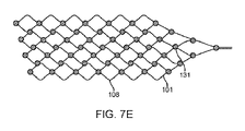
これに代えて、デバイス100は、任意の適切な構成で配置された任意の適切な数の電極131を有するステントを含む。例えば、電極は、以下のように構成することができる。図7Bに示す電極131の正弦曲線配置;図7Cに示す電極131のらせん状配置、これにより、いったん展開されると電極を血管壁に360度接触させることができる;図7Dに示す電極131の幅の低減された正弦曲線配置、これにより、カバーする範囲が広くなるが、なお縦の区域の各々に1つのステントのみ確実に配置する;図7Eに示す電極の高密度配置、これにより、カバーする範囲が広くなる。ステント101は、電極の取り付けおよび電極位置の一様性を支援するために、電極131が配置される箇所に追加の材料またはマーカーが設けられるように、レーザー切断されるか、あるいは織り込まれる。例えば、ステント101を、円筒状のチューブ(原形のステント)からレーザー切断して切り離すことによって形成し、例えば、電極を5mm間隔で1本の軸上に配置する場合には、電極取り付けプラットフォーム107,108は、これらの領域をチューブから切り離すことなく形成することができる。同様に、ステントがワイヤラッピングによって製造される場合、追加の材料107,108をステントワイヤに溶接または取り付けることにより、電極を取り付けるプラットフォームを設けることができる。これに代えて、ステントは、薄膜技術を用いて製造することができ、ステント構造体および/または電極アレイを成長または構築するために材料(ニチノールおよび/または白金および/または他の材料またはこれらの組み合わせ)を特定の位置に堆積させる。
Alternatively,
電極 electrode
図8Aに特に示すように、デバイス100は、ストラットクロスリンク109に連結された電極配置部107を含む。配置部107は、電極131をステントに連結するために使用される。図8Bに配置部106の別例を示す。本実施形態では、配置部は円形である。
As particularly shown in FIG. 8A,
図示のように、電極131は、ステントクロスリンク109の上またはステントクロスリンク109上に配置されている。これらの位置に電極を配置することにより、電極の完全性に大きな影響を与えることなく、ステント101の形状を変化(すなわち、膨張および収縮)させることができる。これに代えて、電極はステントストラットクロスリンクの間(図示せず)に配置されてもよい。
As shown,
図9は、平坦なディスク161;円筒部またはリング162;半円筒またはリング163;球、ドームまたは半球164;双曲線パラボロイド165;並びに一本の軸に沿って優先的に長い二重電極または電極166を含む異なる電極形状を示すがこれらに限定されるものではない。
a cylinder or
図10に示すように、電極131は形状記憶材料を含むことが好ましく、したがって電極131はデバイス100の絶縁されていない部分であってもよい。図示のように、患者の体内の電極131および血管104は妨げられない。形状記憶の活性化の後、電極131は、血管壁103によく適合するように整合する。
As shown in FIG. 10,
デバイス100の接触および機能性を高めるために、電極131は、ステント101へのはんだ付け、溶接、化学蒸着および他の取り付け方法による追加の材料(形状記憶合金または他の導電性材料)の取り付け部を含む。取り付け部は、ステントストラット108の上または間に直接的に;電極131から無線遠隔測定リンクまたは回路に通じるリード線14に;およびデバイス100の遠位面に配置されたオリーブ112に直接的にまたはステント軸体に直接的に設けられるが、これらに限定されない。
デバイス100の性能をさらに向上させるために、1本のワイヤストランド141当たり1つ以上の電極131を設け、1つのデバイス100当たりに利用される1本以上のストランド141を設けてもよい。これらのストランド141は、図11に示す態様でステントストラット108の周囲の交互の正弦曲線経路で織り込まれた束144を形成するようにグループ化することができる。同様に、各電極131に指定された1本または複数の電線141が設けられ、これにより、デバイス100当たりに1つまたは複数の電極131が設けられてもよい。したがって、複数の電極131を同時に使用することができる。
To further improve
電極131が媒体(神経組織、血管組織、血液、骨、筋肉、脳脊髄液を含むが、これらに限定されるものではない)を刺激または記録する能力を最適化するために、電極131は、電極131の各々が同じ配向において血管103と接触可能となるように標的血管103の直径に基づき予め定められた間隔で位置される(すなわち、すべての電極が配置時に左の血管壁に面し、接触する)。電極131は、記録または刺激が血管の360度全体に同時に向けられるように取り付けられてもよい。同様に、電極131の記録および刺激パラメータを高めるために、電極の寸法を変更してもよく、より大型の電極131を使用して近くの媒体のより大きな領域を評価し、より小型の電極131を使用して特定の局地を評価してもよい。
To optimize the ability of
これに代えて、電極131は、導電性材料で形成されるとともに1つ以上のステントに取り付けられ、これによりデバイス100を形成するとともに複数の位置を可能にする。本実施形態では、電極131は、白金、白金-イリジウム合金、ニッケル-コバルト合金、または金などの一般的な電気的に活性な材料から形成され、はんだ付け、溶接、化学蒸着および他の取り付け方法によって電線141に取り付けられ、これらは1本以上の形状記憶軸体に直接取り付けられてもよい。電極131は、好ましくは、絶縁リード線141上の1つ以上の露出部分であり、電極リード線は、1つ以上の形状記憶バックボーンの周囲に巻かれてもよい。1つの形状記憶バックボーンの周囲に巻かれた1つ以上の電極およびリード線が設けられ、複数の形状記憶バックボーンが1つのデバイスで使用され、バックボーンが異なる初期挿入位置および2次的配置位置を有してもよい。以上のように、これらは、複数の血管を同時に標的とするために使用することができる。
Alternatively,
図12に示すように、電極131は、物質134と、抗血栓性物質を含むがこれに限定されない治療薬などの溶液と、材料との担体となるように構成可能である。本実施形態では、電極131は、拡散により受動的に、または埋め込まれた電気クロックによる制御を通じて、あるいは手動で電極131の電気刺激によって薬物を放出するように構成される。本実施形態では、電極131は、導電性ではない電極131の部分を有する材料から形成される。
As shown in FIG. 12,
薬物134は、好ましくは、タイミングがとられた、自然な、電気的な、または他の方法で活性化される際に血管104内に放出されるか、血管壁103内に放出される。
電極線 electrode wire
電極線141は、図13aに示すように、各電極に電気的に連結されている。図示のように、電極の背面、および電気取り付け部135は、非導電性物質136で覆われている。
An
リード線141は、好ましくは、ステント101の周囲に軸体121に沿って巻かれている。
図5A、図5B、および図13bに示すように、電極リード線141は絶縁材122で覆われる軸体121の周囲に巻き付けられ、電線束またはケーブルを形成する。スリーブ153が接点151の位置で電線束を包囲し、これによって少なくとも1本の電線141がスリーブ153の周囲に巻き付けられるとともに接点溶接点152で接点151に接続される。オーバーモールド154により、接点間で一様な直径をなすことができる。
As shown in Figures 5A, 5B and 13b, the
スリーブ153は、ワイヤ141の露出部分が溶接点152で接点151に取り付けられた状態で電線束142を覆う。
ワイヤ141を介してステント101に取り付けられた遠位電極および/またはマーカーおよび/または緩衝器(112)もまた図示される。軸体121は、ステントの着脱領域115の端部に取り付けられ、スリーブ142および電極接点151を通ってコネクタ固定点155を越えて後に出るように示されている。
Distal electrodes and/or markers and/or buffers (112) attached to
リード線141は、スリーブ142の内部に位置し、軸体121の周りに巻き付けられており、接点溶接部152で電極接点151と電気的に接触している。接点間でデバイスが確実に一様な直径をなすためのオーバーコート154が示されている。軸体121は、離脱領域115で取り外されるが、血管内に配置された後に取り外されてもよい。
The
図13bに示すように、リード線141は電極接点151に接続されている。電極リード線141は、まず、絶縁体122に覆われた軸体121の周囲に巻き付けられ、電線束またはケーブルを形成する。スリーブ153が接点の位置で電線束の周囲に配置され、これによって少なくとも1本の電線141がスリーブの周囲に巻き付けられるとともに接点溶接点152で接点151に接続される。接点間で確実に一様な直径をなすためにオーバーモールド154が使用されてもよい。
図5Bに特に示すように、ステント軸体121は、絶縁層122でコーティングされ、143で絶縁されるとともにその周囲に巻き付けられた絶縁束142内にグループ化されている複数の電線141を有する。スリーブ153は、電線141の露出部分が溶接点152で接点151に取り付けられた状態で電線束142を覆う。
As particularly shown in FIG. 5B,
電線141は、白金、白金/タングステン、ステンレス鋼、ニチノール、白金/イリジウム合金、ニッケル-コバルト合金を含むがこれらに限定されない導電性材料、または他の導電性材料および生体適合性材料から形成される。
電線141は、10um乃至100umの径(直径)で、ストランドケーブルまたはモノフィラメントであり、電極131を接点151に接続する。これに代えて、電線141は、電極131をステントまたは軸体上に保持される無線回路に接続する。
The
電線141は、非導電性材料(すなわち、テフロン(登録商標)またはポリイミド)で絶縁されている。電線141は、図11に示すように、正弦曲線パターンでステントストラットの周囲に巻き付けられる。これに代えて、電線141は、直径が300μm乃至2mm(厚み)の電線または束を有するらせん管また電線束またはケーブルで包囲される。
電線141は、ワイヤラッピング、導電性エポキシ、溶接、または他の導電性接着または接続手段を使用して接点151に接続される。
オリーブ olive
図5Aに示す実施形態では、デバイス100は、穿孔の危険性を低減するとともに移植および配置段階中のデバイス100の安全性を高めるために先端に取り付けられたオリーブ112を含む。この構成では、オリーブ112はデバイス100の前方に直接接続され、展開中に展開カテーテルまたは血管と接触するデバイスの第1の態様である緩衝器として機能する。オリーブ112は、放射線不透過性遠位マーカーとしてさらに使用することができる。オリーブ112は、限定するものではないが、以下を含む多くの異なる形態で構成され、ステント101に取り付けられ得る:
In the embodiment shown in FIG. 5A,
i.可撓性を備えたコード i. Flexible cord
図5Aに示すように、オリーブ112は、ステント101の前方から距離をおいて配置され、可撓性を備えたコード114を介してステント101に接続されている。
As shown in FIG. 5A, the olive 112 is spaced from the front of the
ii.スプリングオリーブ ii. spring olives
図14は、ステント101の遠位端に配置されたオリーブを示し、オリーブは、電気的に活性であってもなくてもよく、可撓性を備えたバネあるいはらせん状に巻かれた電線111によってステント101に接続された電極112として機能する緩衝器からなる。
FIG. 14 shows an olive placed at the distal end of
iii.複数のオリーブ iii. multiple olives
図15は、ステント101の遠位端に配置された複数のオリーブを示し、オリーブは、電気的に活性であってもなくてもよく、電極113として機能する複数の緩衝器からなる。
FIG. 15 shows a plurality of olives positioned at the distal end of
iv.ショートオリーブ iv. short olive
図16は、ステント101の遠位端に配置されたオリーブを示し、オリーブは、ステントの端部に直接接続され、電気的に活性であってもなくてもよく、電極112として機能する。
FIG. 16 shows olives placed at the distal end of
v.形状を形成されたワイヤーオリーブ v. shape formed wire olive
図17は、ステント101の遠位端に配置されたオリーブを示し、オリーブは、電気的に活性であってもなくてもよく、電極として機能し、牧杖部114として形成されてもされなくてもよい可撓性ワイヤである。
FIG. 17 shows an olive positioned at the distal end of
vi.ワイヤーオリーブ vi. wire olive
図18は、ステント101の遠位端に配置されたオリーブを示し、オリーブは、電気的に活性であってもなくてもよく、可撓性ワイヤ114によってステント101に接続された電極112として機能する。
FIG. 18 shows an olive positioned at the distal end of
vii.離脱領域付きオリーブ vii. Olive with breakaway area
図19は、ステント101の遠位端に配置されたオリーブを示し、オリーブは、電気的に活性であってもなくてもよく、可撓性ワイヤ114によってステント101に接続された電極112として機能する。この図は、着脱領域115を介してステント101に接続された軸体121をさらに示す。
FIG. 19 shows an olive placed at the distal end of
図20は、着脱領域115を介してステント101から取り外された軸体121をさらに示す。
FIG. 20
可撓性ワイヤ114は、緩衝器を前面に有する導電性かつ電気絶縁性のワイヤ、バネ、らせん状リード、およびチューブを含むが、これらに限定されるものではない。これに代えて、緩衝器は導電性であり、ステント装着電極の全ての特徴を含む電極として機能する。
植え込みチップ implant tip
電極131の刺激および測定を制御するために、植え込み電気回路(チップ)を使用することが好ましい。チップは、チップが信号を伝達する能力を有する電極の位置(またはステント上に取り付けられた他の場所)に移植することができる。このチップは、(a)信号増幅、(b)信号多重化、並びに(c)電力およびデータの送信のための回路を含む。
An implanted electrical circuit (chip) is preferably used to control stimulation and measurement of
電極131は、1つまたは複数の電気チップに取り付けられる(これにより、チップは、電気回路並びにチップが構築される基板として定義される)。小型化されたチップは、ステント101上に電極131と同様に取り付けられる。
The
これに代えて、これらのチップは、頸部または胸部領域のような神経記録または刺激部位から離れて取り付けられてもよく、あるいはチップは、電流源、記録機器またはプロテーゼのような外部ハードウェアに直接接続されてもよい。 Alternatively, these chips may be mounted away from the nerve recording or stimulation site, such as the neck or thoracic region, or the chips may be attached to external hardware such as current sources, recording equipment, or prostheses. May be directly connected.
チップは、好ましくは、神経組織の刺激のための回路(電流および/または電圧源、電池および/またはコンデンサまたは充電/エネルギー保存コンポーネントおよびスイッチマトリックスなど)および神経活動の記録用回路(増幅器、電力、およびスイッチマトリックスなど)および血液組成(例えば、pHメーター、塩類および生理食塩水組成、グルコースなど)を含む。 The chip preferably includes circuits for stimulation of neural tissue (current and/or voltage sources, batteries and/or capacitors or charge/energy storage components and switch matrices, etc.) and circuits for recording neural activity (amplifiers, power, and switch matrices, etc.) and blood composition (eg, pH meter, salt and saline composition, glucose, etc.).
さらに、チップは、熱センサなどの遠隔測定コイルおよび自己監視ハードウェアを介して電力およびデータを送信するために必要な回路を有してもよい。 Additionally, the chip may have the necessary circuitry to transmit power and data through telemetry coils and self-monitoring hardware such as thermal sensors.
図5Cに無線チップ195を示す。マイクロプロセッサ191ならびに他の構成要素193(例えば、コンデンサ、マルチプレクサ、クロック、無線送信機、受信機など)が示されている。この図は、大型のコイル192および小型のコイル194として示されている、電力とデータの両方の送受信に使用できる2つのコイルを有する。
A
チップ自体は、送信および受信の電力およびデータ用の遠隔測定コイルを含んでもよく、隣接するチップおよび遠隔測定コイルとの位置合わせを可能にする磁石を含んでもよく、あるいは遠隔測定コイルを構成する形状記憶合金または他の材料に取り付けられてもよい。 The chip itself may contain telemetry coils for transmit and receive power and data, may contain magnets to allow alignment with adjacent chips and telemetry coils, or may be shaped to make up the telemetry coils. It may be attached to a memory alloy or other material.
チップは、好ましくは可撓性を備え、血管内にチップを配置するために、血管の直径部分に対してあらかじめ湾曲させてもよい。これにより、チップは、配置段階の間にチップを血管の湾曲に適合させるための形状記憶合金またはポリマーを含んでもよい。チップはまた、血管内での統合を可能にするために、生体吸収性または生体分解性を備える基板上に搭載されてもよい。複数のチップを同時に使用してもよい。 The tip is preferably flexible and may be pre-curved with respect to the diameter of the vessel for placement of the tip within the vessel. Thereby, the tip may include a shape memory alloy or polymer to adapt the tip to the curvature of the vessel during the deployment phase. The chip may also be mounted on a bioabsorbable or biodegradable substrate to allow for intravascular integration. Multiple chips may be used simultaneously.
f.接点 f. contact
図5Aおよび図5Bに特に示すように、無線回路が使用されていない状況では、デバイス100を外部機器に接続できるように、電極接点151が必要とされる。電極接点151は、好ましくは、電極によって使用されるものと同様の材料から形成され、同様の直径である。接点151は、互いに電気的に絶縁されており、導電性エポキシ、レーザーまたは抵抗溶接、はんだ付け、圧着および/またはワイヤラッピングによって(ただしこれらに限定されるものではない)電極リード線141に接続される。
As particularly shown in FIGS. 5A and 5B,
接点151は、白金リングまたは他の導電性、生体適合性材料のリングである。接点は、磁性材料(すなわち、ネオジム)から形成可能であり、またはそれを含むことができる。 Contact 151 is a platinum ring or ring of other conductive, biocompatible material. The contacts can be formed from or include a magnetic material (ie, neodymium).
接点151は、(a)直径が500μm乃至2mm、(b)長さが500μm乃至5mm、および(c)厚みが10um乃至100umにあることが好ましい。
The
接点151は、ディスク、チューブ、パラボロイド、または電極131に使用されるものと同様の他の形状として形成される。
Contact 151 is formed as a disc, tube, paraboloid, or other shape similar to that used for
接点は、他のリード線および電極およびステントワイヤの電気的絶縁を補助するために、非導電性スリーブ(シリコーンチューブ、熱収縮、ポリマーコーティングを含むが、これらに限定されるものではない)を覆うように配置されるが、いくらか可撓性を備える。 The contacts cover a non-conductive sleeve (including but not limited to silicone tubing, heat shrink, polymer coating) to aid in electrical insulation of other leads and electrodes and stent wires , but with some flexibility.
好ましくは、接点151は、100μm乃至10mmの接触部間分離部を有する。
Preferably, the
接点151は、電線141のワイヤラッピングによって形成されている。
The
好ましくは、少なくとも1つの接点151は、(金属リング、磁気リング、プラスチックチューブを含むが、これらに限定されるものではない)ダミーコネクタである。この場合のダミーコネクタは、電極と電気的に接触していないコネクタであり、これに代えてその目的は、所望の位置でデバイスへの接続点または固定点(すなわち、ねじ端子を介して)を可能にすることであり、(電極に接続された)接点は損傷を受けない。
Preferably, at least one
接点151は、電気的ノイズを低減するとともに表面リード線141間の接触を防止するために、非導電性スリーブ(シリコーンチューブ、熱収縮、ポリマーコーティングを含むが、これらに限定されるものではない)によって分離される。
g.軸体 g. shaft
図21aに示すように、展開を可能にするために、可撓性を備える軸体121がデバイス100に接続される。図21aに示す例では、軸体121は、デバイス100の遠位端に接続され、これによりデバイス100を前方から張引するように作用する。
As shown in Figure 21a, a
図21bに示す代替の実施形態では、軸体121がデバイス100の近位端に取り付けられ、これにより軸体121がステント101の背面からデバイス100を押圧する。本実施形態では、医療デバイス100は、ステント101に取り付けられた複数の電極131を含み、電極リード線141がステント101および軸体121の周囲に巻き付けられるとともにスリーブ142で覆われている。遠位電極および/またはマーカーおよび/または緩衝器113も、ステント着脱領域105と同様に示されている。
In an alternative embodiment shown in FIG. 21b, a
図21cに示すさらなる実施形態は、二重の先端ほど細くなるステント101を含み、これは、取り付けられた電極131と、ステント着脱領域105においてステント101に取り付けられるステント軸体121とを含む。ステント101の前面の別の着脱領域115は、ステント101をオリーブワイヤ114およびスタイレットスリーブ124に接続し、スタイレットスリーブ124を通して着脱自在なスタイレット123が配置される。電極電線141は、スタイレットスリーブ123の外側に巻き付けられているか、または中心を通って供給されるように示されている。
A further embodiment shown in FIG. 21 c includes a double tipped
プッシュとプルの両方の能力を有する複数のワイヤが設けられてもよい。ステント軸体121は、恒久的に移植されてもよく、または取り外されるように構成されてもよい。本実施形態では、着脱領域は、ステント軸体121とステント101との接合部に配置される。分離方法には、電気化学的分離、機械的分離、および熱電分離が含まれるが、これらに限定されるものではない。
Multiple wires may be provided that have both push and pull capabilities.
ステント軸体121は、電極リード線141のバックボーンとして使用することができ、これにより、電極リード線141が電極131から電極接点を横断する際の安定性を支援する。本実施形態では、電極電線141は、付加的に機械的に支持するとともに水分の保持を支援し、ワイヤが存在するステント軸体上にコーティングを堆積させるためのポリマー142(シュリンクラップ、熱収縮、パリレン、シリコーン、テフロン(登録商標)などを含むが、これらに限定されるものではない)に設けられる。
The
ステント軸体121は、デバイス100の植え込みおよび配置後に取り払われるスタイレットであってもよい。本実施形態において、ステント軸体121は、スタイレット123がチューブ121の中心を通して供給され得るような円筒状のチューブであってもよい。
電線141は、好ましくは、スタイレットスリーブの中央を通るスレッドである。
好ましくは、電線141は、ステント軸体またはスタイレットスリーブの周囲に巻き付けられる。
Preferably, the
さらなる実施形態では、電極131を接点152に接続する電極電線141は、ワイヤ束144に包囲され、内部ルーメン147が設けられるように内部ルーメンチューブ145の周囲に巻き付けられ、内部ルーメン147に取外し可能なスタイレット148が挿入中に通され、展開後に取り外され得る。本実施形態により、スタイレット148の取り外し可能性と、外部チューブ146に覆われたワイヤ束144の可撓性とが実現される。
In a further embodiment, the
図21dおよび図21eは、らせん状リード線114に関する追加の情報を示す。図示のように、らせん状リード線114は、内部ルーメンチューブ145の周囲に巻かれたワイヤ束144を含む。内部ルーメン147を通して、取外し可能なスタイレット148が、送達中に通され、デバイスの配置に続いて取り払われ得る。
21d and 21e show additional information regarding the
制御部 control unit
図2に示す制御部12は無線コントローラであり、皮膚を介して無線で情報および電力を中継する。
The
図22、図23、および図24のコネクタブロック12は、受動デバイス(すなわち、回路なし)である。実質的に、コネクタブロック12は、デバイス100と外部機器との間の中間接続として機能する。デバイス100はコネクタブロック12に挿入され、これにより、デバイス100はコネクタブロック12内に収容された内部接点と電気的に接触する。コネクタブロック12のこれらの内部接点は、皮膚を貫通するより厚みのあるワイヤ束を続いて形成し(コネクタブロックの残りの部分が植え込まれる)、外部機器に接続することができる。
The connector blocks 12 of Figures 22, 23 and 24 are passive devices (ie, no circuitry). In effect,
実質的に、空間が限られているため(デバイス全体がカテーテルを通過しなければならないため、カテーテルを植え込み後にデバイス上から取り払う必要がある)、コネクタブロックにより、より大型の要素を薄型デバイス100に取り付けることができる。
In effect, due to space limitations (the entire device must pass through the catheter, and the catheter must be removed from the device after implantation), the connector block allows larger elements to be integrated into the
図22、図23および図24に示す実施形態は同じであるが、図24のみが皮膚を通過するワイヤを示している。 The embodiments shown in Figures 22, 23 and 24 are the same, but only Figure 24 shows the wires passing through the skin.
図22に示す制御部12は、リード線14を受承するとともにリード線14と電気的に接続するような形状に形成される。制御部は、内側に取り付けられた接触リングを含む。ここで、コネクタブロック12は、溝付き端部にシリコーンおよび/または縫合糸を取り付けることによって固定され、水密性が確保される。
The
ステントに直接植え込まれる無線システムは、図2の無線システム12と本質的に(小型化されたバージョンでも)同じである。
A wireless system implanted directly into a stent is essentially the same (even in a miniaturized version) as
図23に示すように、電極リード線14を挿入し、シリコーンガスケットを使用して水密シールを行う。 As shown in FIG. 23, the electrode leads 14 are inserted and a watertight seal is made using a silicone gasket.
図24は、電極リード線14が接続開口部172を通され、これにより、コネクタブロック本体173内の導電性コネクタ175と接触するコネクタブロックを示す。分離および電気絶縁および水密性は、シリコーン(またはその他の)セパレータ174を介して高められる。接点175は、無線または直接的な電気接続ポート183で終端するためにシリコーンまたは他のもので包囲された束181を形成するコネクタブロックワイヤ179に溶接(または別の方法で接続)される。
FIG. 24 shows the connector block with electrode leads 14 threaded through
システムを使用する方法 How to use the system
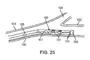
デバイス100は、図25に示す挿入位置と図26に示す配置または足場位置との間で移動可能である。
挿入位置では、デバイス100は、収縮し、これにより、カテーテル内から進入点(すなわち、頸静脈)から配置点(例えば、運動皮質)までの脈管系経路を通るように、十分に肉薄となる。
In the insertion position, the
配置または足場の位置に配置されると、デバイス100は、足場電極が血管壁に対して押し付けられた状態でステント101の外側に取り付けられた拡張状態にある。この拡張された位置は、デバイス100を血管103内のその位置にアンカー固定する。さらに、この配置位置は、デバイス100が配置される血管103を通る血流の完全性に最小限の効果を有するように構成される。足場位置は、バネ、コイル、あるいはらせん状のストランドと同義であってもよく、これにより、デバイス100は血管壁にのみ接触し、血流への影響を低減する。電極131はまた、ステント101の内部に取り付けられてもよく、これにより、拡張ステント101を流れる流体からの情報を測定することができる。ステント101を取り払いまたは再配置するためには、追加の軸体(初期展開に使用されるもの以外)が必要である。これらは、本発明の文脈で説明されており、単一の先端ほど細くなる構成および二重の先端ほど細くなる構成の両者が用いられる。
When placed in a deployment or scaffolding position,
デバイス100を複数の位置に配置できるように、使用される材料は、複数の状態が可能なものである。これらの材料には、ニチノールおよび他の形状記憶合金およびポリマーが含まれるが、これらに限定されるものではない。さらに、デバイス100の長期間の生体適合性を高めるために、ポリマーは、生体吸収性または生体分解性を備えるものであり、線維化がデバイス100上で生じる時間と同様の分解時間を伴い得る。したがって、電極131(好ましくは劣化するように構成されておらず、ニチノール、形状記憶合金、導電性ポリマー、他の非形状記憶合金、並びに白金、イリジウム、ステンレス鋼および金のような不活性かつ生体適合性を備える金属から形成される)は、初期デバイス100に残っているすべてであり、血管103の内部に埋め込まれ、これにより、配置位置におけるデバイス100の安定性がさらに高められる。
The materials used are capable of multiple states so that the
血管内におけるデバイス(展開後) Intravascular device (after deployment)
図6は、拡張または配置または足場の位置にある医療デバイス100を示す。デバイス100は、ステント101、遠位オリーブおよび/または近接マーカー112、ステント101をオリーブ112に取り付けるワイヤ114、複数の電極131、および軸体が、血管104内に展開されているステント101に接続される着脱領域115を含む。ステント101に取り付けられた電極131は、血管壁103と直接並んでおり、任意の血管(デバイスが展開されている血管と他の接続された血管の両者)への血流を妨害しないものとして示されている。ここでは、オリーブ112を使用して、医療器具を所望の血管104内に配向可能である。
FIG. 6 shows the
血管の前展開におけるデバイス Devices in predeployment of blood vessels
図25は、カテーテル102内で血管104を通される際の移植中(外科的展開段階)の医療デバイス100を示す図である。血管壁103と同様に、ステント101、電極131、ステント離脱領域105、およびステント遠位マーカー/電極/緩衝器113が示されている。ここでは、カテーテル102を使用して、デバイスを選択するとともに所望の血管104内に配向する。
FIG. 25 illustrates
展開後の血管内のデバイス Intravascular device after deployment
図26は、配置カテーテル102を通して血管104内に展開されているステント101、遠位オリーブおよび/または近接マーカー113、複数の電極131、リード線141およびステント離脱領域105を含む、拡張または配置または足場位置における医療デバイス100を示す。ステント101に取り付けられた電極131は、血管壁103と直接並んでおり、任意の血管(デバイスが展開されている血管と他の接続された血管の両者)への血流を妨害しないものとして示されている。
FIG. 26 shows an expansion or deployment or
接地電極 ground electrode
システムは、好ましくは、図27に示すように構成された接地電極167を含み、これは、記録された信号の品質を補助するとともに改善し、あるいは刺激用途のための電気戻り経路を提供するために使用される。ここで、接地電極は、それが移植されるならば、コネクタブロック上に配置される。接地電極167は、好ましくは、無線コントローラ12の外部に直接取り付けられる。
The system preferably includes a
図28に別の実施形態による接地電極167を示す。接地電極167はコントローラ12の外側に設けられる。
A
図37に示す白金のC字状の接地電極167は、標準の電気端子169に取り付けられた赤色のらせん状のリード線141とともにシリコーン181に埋め込まれている。ダクロンメッシュは、電極およびワイヤを組織に固定するのを支援することに使用される。
A platinum C-shaped
図29は、異なる領域にアクセスするために異なる血管104に挿入された複数のデバイス100を有する血管を示す。
FIG. 29 shows a vessel with
図30は、より大きな領域を覆うように植え込まれた複数のデバイス100を有する1本の血管104を示す。
FIG. 30 shows a
図31は、神経情報をピックアップするとともにこの情報をステント101上に配置された無線送信機1002に中継する、ヒトの運動皮質の上にある血管104内のステント101に取り付けられた電極を示す無線電極システム1000である。ステント101が展開され、スタイレットが取り払われている(すなわち、ステント101、電極、電極ワイヤ、および無線システム1002のみが残っている)ことに留意されたい。情報は、頭蓋骨を介して頭部に配置された無線受信部1004に無線で送信され、次に、取得された神経情報は復号されるとともに義足16に送信される。
FIG. 31 shows wireless electrodes attached to a
図32に示すように、デバイス100は、デバイス100を使用して患者の上矢状洞(SSS)または分枝皮質静脈から神経情報を記録または神経細胞を刺激するために使用され、(a)上矢状洞または分枝皮質静脈のいずれかにデバイスを植え込む工程と、(b)活動を受信する工程と、(c)前記活動を表すデータを生成する工程と、(d)前記データを制御部に送信する工程とを含む。ステント101は、ワイヤを介して外部機器12に供給される信号を取得する(すなわち受信する)、運動皮質を覆うSSSに植え込まれる。
As shown in FIG. 32,
図33は、運動皮質(赤色)および感覚皮質(黄色)付近の上矢状洞および分枝皮質静脈を示すヒトの脳(眼が左に面した)の画像再構成を示す。 FIG. 33 shows an image reconstruction of the human brain (eye facing left) showing the superior sagittal sinus and branch cortical veins near the motor cortex (red) and sensory cortex (yellow).
図34は、デバイス100を使用して神経細胞を刺激するとともに患者の視覚皮質から神経情報を記録する方法を示しており、(a)患者の視覚皮質の血管内にデバイスを移植する工程と、(b)血管に関連付けられた神経情報を記録するとともに受信した刺激データに従って神経細胞を刺激する工程とを含む。
FIG. 34 illustrates a method of using
図35に特に示すように、デバイス100は、筋肉を直接的に刺激または記録するために配置される血管104を通して送達される。
As particularly shown in FIG. 35, the
デバイス100は、刺激または記録のために末梢神経に隣接する血管を通して送達され得る(図35に示されるような)。
デバイスは、刺激または切除のために、交感神経または副交感神経に隣接する血管を通して送達される。 Devices are delivered through vessels adjacent to the sympathetic or parasympathetic nerves for stimulation or ablation.
図36は、神経刺激または測定ができるような可能な位置を示す末梢神経(この例では正中神経)の一例を示す。 FIG. 36 shows an example of a peripheral nerve (the median nerve in this example) showing possible locations where nerve stimulation or measurements can be made.
図38Aは、ステント101本体の周囲に配置された複数の電極131を有するステントまたは足場101の別の例を示す。図示のために、ステント101は、上述のようにリード線、あるいは電極と制御部との間の電気的通信を可能にする他の構造体に対して電極を電気的に結合するいかなる接続構造体も伴わないものとして示されている。図示の変形例では、電極131は、ステント101の本体の周囲に分散されるとともに接合ストラット108の接合部または頂点に配置される。このような構造体では、ダイヤモンドのような形状のセルを有する代わりに、セルは「V」字状の形状に形成される。この構造体により、電極131と組織または血管壁との間の並置を強化することができる。
FIG. 38A shows another example of a stent or
図38Aはまた、ステント構造体が、ステントストラット108の一部またはそれ以上を貫通して延在する一体化された導電層を含み、電極131が、一体化された導電層の露出部を通して形成されるように形成可能なステント101の変形例を示す。このようなステント構造体により、以下に詳述するように、ステント101および電極131のアセンブリが形成可能となり、電極および導電性電極トラックがステント格子またはストラット自体に埋め込まれる。このような構成により、電極をステントの本体に取り付けるための固定方法(すなわち、接着剤、のり、固定具、溶接など)を使用する必要性が低減または排除される。このような構成により、電極をワイヤにさらに溶接または電気的に接続する必要性がさらに低減または排除される。別の効果は、従来のワイヤ接続電極は、ステントストラットの周囲およびステントの本体を通るワイヤの収容を必要とすることにある。
FIG. 38A also shows that the stent structure includes an integrated conductive layer extending through some or more of the stent struts 108, with
図38Bは、一体化された電極131を有するステント構造体101を示しており、ステント構造体は、遠位端146で軸体121に連結されている。軸体は、本明細書に開示されるように、電極131を後述のように1つ以上の制御部(図示しない)に電気的に連結することができる。一例では、軸体121は、ガイドワイヤ、プッシュワイヤ、並びにワイヤまたは導電性部材が内部を延びるとともに遠位端146でステントの導電層に連結されるその他の管状構造体を備えることができる。これに代えて、図38Cおよび図38Dは、軸体121がステント構造体の一部または一体であり、導電層がステントの一部または全部を通って軸体121まで延在するように形成することができるステント101のバリエーションを示す。このような構造体により、ステントの作業端で軸体をステント構造体に接合する必要性がさらに排除される。これに代えて、ステント構造体(軸体を形成する)を個別の軸体に接合することにより、デバイスに沿って近位側に移動させることができる。このような構造体により、ステントおよび軸体の作業端は可撓性を備えた状態に保持される。図38Cおよび図38Dに示すステント構造体はまた、上述のような任意の補強部分62を含むことができる。図38Cは、スタイレット123を挿入してデバイスの位置決めを補助することができるか、ワイヤまたは他の導電性部材をその内部に通してこれらと連結することができる中空軸体121をさらに示す。さらに、軸体121は、脈管構造を通る軸体の可撓性または押し込み性を向上させる任意の数の要素119を含むことができる。
FIG. 38B shows
1つ以上の接続パッド(以下に説明する電極と同様の構造)の構成によって、デバイスを通って延在するリード線に対して電極131を電気的に接続することができ、パッドの寸法によりワイヤまたはリード線に十分に確実に接触し、パッドのタイプにより波形にするとともに取り付ける際の堅牢性が保証されるとともにトラックの疲労が低減される。パッドを含む区分は、ケーブル121が挿入できるように、例えば遠位部146でチューブに圧縮することができる。
The configuration of one or more connection pads (structures similar to the electrodes described below) allows the
特定の変形例では、接続パッドはカテーテルを通って供給可能でなければならない。さらに、接続パッド132は、パッドがリード線上の接点に整列していることが視覚的に確認可能となる1つまたは複数の穴または開口部を含むことができる。これらの穴/開口部により、接触リード(チューブ121の内側)と接触パッド(穴を通して外側に延在するチューブの内側の)との直接/レーザー溶接または接着がさらに可能となる。 In certain variations, the connection pads must be deliverable through the catheter. Additionally, the connection pads 132 may include one or more holes or openings that allow visual confirmation that the pads are aligned with the contacts on the leads. These holes/openings further allow direct/laser welding or gluing of the contact leads (inside the tube 121) and the contact pads (inside the tube extending outward through the holes).
一実施例では、同軸オクトファイラケーブル(すなわち、8本のワイヤを有する外側ケーブルの内側に配置される8本のワイヤを有する内側ケーブル)を使用して、耐疲労性を強化し、ワイヤを制約内に確実に収めることができる(すなわち、十分に小型のカテーテルを通し、必要に応じて内側スタイレットを有することができる)。 In one example, a coaxial octofilar cable (i.e., an inner cable with 8 wires placed inside an outer cable with 8 wires) is used to enhance fatigue resistance and constrain the wires. (ie, a small enough catheter can be passed through and have an internal stylet if desired).
図39A乃至49Cは、埋め込み電極および導電路で構成されたステント構造体101の一例を示す。図39Aは、例示のみの目的のために、線状配置の電極138を有する平面構成のステント構造体101の例を示す。明らかに、電極の任意の構成は、本開示の範囲内である。具体的には、神経用途に有用なステント構造体の変形形態では、ステント構造体は、既存の神経ステントよりも伝統的に大きい直径を含むことができる。そのような増大した直径は、ステント構造体が恒久的に埋め込まれ、血管/組織壁に対する電極の並置を必要とするために有用であり得る。さらに、いくつかの変形例では、そのようなステント構造体の長さは、人間の運動皮質に沿った所望の配置を収容するために、20mmまでの長さおよび20mmよりも大きい長さを含むことができる。例えば、デバイスのバリエーションは、運動皮質および周辺皮質領域を覆うのに十分な長さのステント構造体を必要とする。このような長さは、流れの回復、あるいは動脈瘤や他の医学的状態への対処を目的とした既存の介入デバイスには通常必要とされない。加えて、特定の変形形態では、特定の電極間の電気経路を絶縁することができる。そのような場合に、導電性材料50は、電極が接触パッドまたは他の導電性要素への電気伝導経路を有することを可能にするパターンを形成するために、所定のステントストラットから省略することができるが、電気伝導経路は、第2の電気伝導経路を有する第2の電極から電気的に絶縁される。
Figures 39A-49C show an example of a
特定のパターン(例えば、コルクスクリュー構成または互いに対して120度の方向に配向される3つの線形(またはコルクスクリュー配向)線の構成)に電極を配置することにより、確実に電極を脳に配向する、展開した電極配向が可能となる。移植されると、外科的に配向は可能ではなくなる(すなわち、デバイスが移植されて、回転することが不可能でない場合には困難となる)。したがって、デバイスの変形は、送達の際に脳の所望の領域に向かう電極パターンを有することが望ましい。 Orienting the electrodes reliably to the brain by placing the electrodes in a specific pattern (e.g., a corkscrew configuration or a configuration of three linear (or corkscrew-oriented) lines oriented at 120 degrees to each other) , allowing for expanded electrode orientation. Once implanted, surgical orientation is not possible (ie, difficult if the device is implanted and rotation is not possible). Therefore, it is desirable for device variations to have electrode patterns directed to desired regions of the brain upon delivery.
電極寸法決めは、確実に十分高品質な記録ができるように、かつ充分大きな電荷注入限界(組織に損傷を与える可能性のある電極を損傷することなく刺激中に電極を通過できる電流の量)を与えるのに十分な大きさでなければならない。寸法はまた、カテーテルシステムによる送達を可能にするのに十分な大きさでなければならない。 Electrode sizing should be used to ensure sufficiently high quality recordings and sufficiently large charge injection limits (the amount of current that can pass through the electrodes during stimulation without damaging the electrodes which can damage tissue). must be large enough to give The dimensions must also be large enough to allow delivery by a catheter system.
図39Bおよび図39Cは、図39Aのステント構造体の線39B-39Bに沿った断面図を示し、MEMS(マイクロ電気機械システム)技術を用いて薄膜デバイスを堆積および構造化して、薄膜デバイスを製造し、ステント格子または複数のストラットに埋め込まれた電極と導電路とを有するステントを構造するための製造技術の一変形例をさらに示す。図39Bおよび図39Cのストラットの間隔は、説明のためにのみ圧縮されている。
Figures 39B and 39C show cross-sectional views along
上述したように、電極および導電路を埋め込むことにより、デバイスの機械的性能に効果が得られる。さらに、電極を埋め込むことにより、構造体上に取り付けられた電極の数を増やすことができ、導電路(30乃至50μm×200乃至500nm)を従来の電極ワイヤー(50乃至100μm)よりも小さくすることができる。 As mentioned above, embedding electrodes and conductive paths has an effect on the mechanical performance of the device. Furthermore, by embedding the electrodes, the number of electrodes attached on the structure can be increased and the conductive paths (30-50 μm×200-500 nm) can be made smaller than conventional electrode wires (50-100 μm). can be done.
薄膜ステントの製造は、犠牲層(58)を予備支持構造体として使用して、ニチノールまたは他の超弾性形状記憶材料(または金、白金、酸化イリジウムを含むがこれらに限定されない、電極および接点の堆積のための他の材料)をマグネトロンスパッタリングによって特定のパターン(56)で堆積させることによって行うことができる。支持構造体(58)を取り払うことにより、UVリソグラフィを用いて薄膜をさらに構造化することができ、構造体は、電極を血管壁に対して固定するのに必要な半径方向の力に対応する厚みにより構成可能である。 Fabrication of the thin film stent uses the sacrificial layer (58) as a preliminary support structure to form Nitinol or other superelastic shape memory materials (or electrodes and contacts, including but not limited to gold, platinum, iridium oxide). Other materials for deposition) can be done by depositing in a specific pattern (56) by magnetron sputtering. By removing the support structure (58), the thin film can be further structured using UV lithography, the structure accommodating the radial force required to anchor the electrode against the vessel wall. It can be configured by thickness.
電極の電気的絶縁は、薄膜構造(54)上への非導電層(52)(例えば、SiO)のRFスパッタリングおよび堆積によって達成される。電極および電極トラック(50)は、(金、Pt、Ti、NiTi、PtIrを含む導電性および生物医学的に許容可能な材料を使用して)非導電層上にスパッタ堆積され、追加の非導電層が、さらなる電気的絶縁のために導電性トラックを覆うように堆積される。図示のように、導電路50は露出されたままであり、電極138を形成する(同様に、接触パッド領域は露出したままであり得る)。最後に、犠牲層58および基板が取り払われ、図39Cに示すようにステント構造体101が残される。
Electrical isolation of the electrodes is achieved by RF sputtering and deposition of a non-conductive layer (52) (eg SiO) onto the thin film structure (54). Electrodes and electrode tracks (50) are sputter-deposited (using conductive and biomedically acceptable materials including gold, Pt, Ti, NiTi, PtIr) onto the non-conducting layer and additional non-conducting A layer is deposited over the conductive tracks for further electrical isolation. As shown,
基部構造体54が超弾性形状記憶材料(すなわち、ニチノール)を含むいくつかの変形例では、ステント構造体101を高真空チャンバ内でアニール処理して、アニール処理中における酸化を回避することができる。熱処理の間、非晶質ニチノール構造体54は結晶化して超弾性を獲得し、所望に応じて円筒形または他の形状に同時に形状設定することができる。構造体101を続いて熱処理することができる。
In some variations in which the
図40Aは、図40Bの線40A-40Aに沿った部分断面図であり、MEMS技術によって形成されるステント構造体101の追加の変形を示し、1つまたは複数のステントストラット108の寸法を変更することにより、ステント構造体101を所望の構造または他の態様にすることができる。例えば、図示の変形例では、特定のステントストラット108は、支持材料60が隣接するステント構造体108よりも大きな厚みを有するように寸法が変更される。しかし、このような寸法変化は、厚みに限定されず、幅、形状などを含むこともできる。
FIG. 40A is a partial cross-sectional view taken along
図40Bは、寸法が変更されたストラットから得られるステント構造体101を示しており、ステント構造体101の正弦曲線部分62はより大きな剛性(増加した厚みにより生じる)を含む。このような構成により、(シースがステントの上で引き戻される)従来の必要条件とは異なり、カテーテルを通してステントデバイスを押し出すことができる。従来のステントは、ニチノールダイヤモンドまたはセルの肉薄な格子から形成される。この正弦曲線部分62は、バックボーンのように機能することができ、超弾性並びにステントが圧縮および拡張する能力を制限することなく、デバイスに前方への押し込み強度を付与する。明らかに、寸法的に変更されたストラット部の任意の数のバリエーションが、本開示の範囲内にある。
FIG. 40B shows a
本発明の範囲から逸脱することなく、多くの改変が当業者には明らかであろう。 Many modifications will be apparent to those skilled in the art without departing from the scope of the invention.
本明細書中の任意の先行技術への言及は、先行技術がオーストラリアにおける技術常識の一部を形成するという承認または任意の形式の示唆であると捉えられるべきではない。 Reference to any prior art herein should not be taken as an acknowledgment or any form of suggestion that the prior art forms part of the common general knowledge in Australia.
本明細書および添付の特許請求の範囲においては、特に断らない限り、「comprise」という単語並びに「comprises」および「comprising」のようなその変形は、記載された完全体、工程、または完全体や工程の群を含むことを意味するが、任意の他の完全体または工程、あるいは完全体や工程の群を排除するものではない。 In this specification and the appended claims, unless otherwise specified, the word "comprise" and variations thereof such as "comprises" and "comprising" refer to the stated entity, step or It is meant to include groups of steps, but not to exclude any other integer or step or group of steps.
本明細書中の任意の先行文献、前記先行文献から得られた情報、または任意の既知の事項に対する参照は、前記先行文献の承認、自認、若しくは示唆と捉えられるべきではなく、あるいはこの先行文献若しくは既知の事項から得られた任意の情報は、本明細書が関係する試みの分野における技術常識の一部をなす。 Reference herein to any prior document, information derived from said prior document, or to any known matter should not be taken as an acknowledgment, admission, or suggestion of said prior document, or that said prior document Or any information obtained from known matter constitutes part of the common general knowledge in the field of attempts to which this specification relates.
Claims (19)
複数のストラットを形成するフレーム構造であって、同フレーム構造は、低減されたプロファイルと前記フレーム構造の直径が増大する拡張されたプロファイルとの間で移動可能である、フレーム構造と、
同フレーム構造を形成する前記複数のストラットのうちの少なくとも1つが、支持材料上に導電性材料を含み、同導電性材料が前記ストラットの少なくとも一部分に沿って延びるとともに非導電性材料で覆われており、
前記ストラットの前記部分上の前記非導電性材料の開口部によって形成される少なくとも1つの電極であって、前記少なくとも1つの電極は、電気生理学的活動を測定しまたは電気刺激を行うように構成された、少なくとも1つの電極と、
前記フレーム構造に結合され、前記フレーム構造の前記内腔内での位置決めを補助するように構成されたステント軸体と、
前記ステント軸体内で前記フレーム構造から離れて延びるリード線であって、前記導電性材料が前記ストラットに沿って延びて前記リード線と電気的に結合し、前記リード線の近位端が移植可能な制御部に電気的に結合可能であるリード線と、を備えることを特徴とする医療デバイス。 A medical device for monitoring electrophysiological activity for use within a blood vessel that is a tubular body having a lumen, comprising:
a frame structure forming a plurality of struts, the frame structure being movable between a reduced profile and an expanded profile that increases the diameter of the frame structure;
At least one of the plurality of struts forming the frame structure includes a conductive material on a support material, the conductive material extending along at least a portion of the strut and covered with a non-conductive material. cage,
at least one electrode formed by openings in said non-conductive material on said portion of said strut, said at least one electrode configured to measure electrophysiological activity or to provide electrical stimulation; at least one electrode ;
a stent shaft coupled to the framework and configured to assist in positioning the framework within the lumen;
A lead extending away from the framework within the stent shaft, the conductive material extending along the strut and electrically coupling the lead, the proximal end of the lead being implantable. a lead that is electrically couplable to a controller.
前記医療デバイスが前記第2のストラットの前記部分上の前記非導電性材料の開口部によって形成される少なくとも1つの第2の電極を備えることを特徴とする請求項1に記載の医療デバイス。 said at least one strut comprising a first strut and further comprising a second strut forming said framework, said second strut comprising a conductive material on a support material, said conductive material comprising: extending along at least a portion of the second strut and covered with a non-conductive material, the conductive material of the first strut being electrically insulated from the conductive material of the second strut; wherein said conductive material of said second strut extends along said strut and is electrically coupled to said lead;
2. The medical device of claim 1, wherein said medical device comprises at least one second electrode formed by an opening in said non-conductive material on said portion of said second strut.
前記神経組織刺激回路は前記少なくとも1つの電極に結合された回路であって、
(i)電流および電圧のうちの少なくともいずれか一方の源と、
(ii)バッテリーおよびコンデンサのうちの少なくともいずれか一方、または充電およびエネルギー貯蔵のうちの少なくともいずれか一方の要素と、
(iii)スイッチマトリクスとのうちの1つ以上を含み、
前記神経活動記録回路は前記少なくとも1つの電極に結合された回路であって、
(i)増幅器と、
(ii)電源と、
(iii)スイッチマトリックスとのうちの1つ以上を含むことを特徴とする請求項10に記載の医療デバイス。 the electronics assembly includes at least one of (a) neural tissue stimulation circuitry and (b) neural activity recording circuitry;
said neural tissue stimulation circuit being a circuit coupled to said at least one electrode ,
(i) a source of current and/or voltage;
(ii) a battery and/or capacitor or charging and/or energy storage element;
(iii) a switch matrix;
said neural recording circuitry being circuitry coupled to said at least one electrode ,
(i) an amplifier;
(ii) a power source;
(iii) a switch matrix;
(i)前記医療デバイスの近位の媒体の活動を表すデータを前記医療デバイスから受信し、
(ii)制御信号を生成し、
(iii)同制御信号を装置に送信する
ように構成されることを特徴とする請求項1に記載の医療デバイス。 a controller configured to communicate with the medical device of claim 1, the controller comprising:
(i) receiving data from the medical device representing media activity proximal to the medical device;
(ii) generating a control signal;
3. The medical device of claim 1, wherein (iii) the medical device is configured to transmit the same control signal to the device.
外骨格と、
義足と、
車いすと、
コンピュータと、
電気的または電気機械的デバイスとのうち少なくとも1つ以上を含むことを特徴とする請求項13に記載の医療デバイス。 The device comprises:
an exoskeleton;
a prosthetic leg;
wheelchair and
a computer;
14. The medical device of claim 13, comprising at least one or more of an electrical or electromechanical device.
複数のストラットを形成するフレーム構造であって、同フレーム構造は、低減されたプロファイルと前記フレーム構造の直径が増大する拡張されたプロファイルとの間で移動可能である、フレーム構造と、
フレーム構造を形成する複数のストラットのうちの少なくとも1つのストラットが支持材料の上に導電性材料を配置して構成され、同導電性材料が前記ストラットの少なくとも一部分に沿って延びるとともに非導電性材料で覆われており、前記複数のストラットは複数のストラットの対を含み前記複数のストラットの対のそれぞれは隣接するストラットに接続しないV字状の頂点を形成し、
前記ストラットのV字状の頂点部分に設けられ非導電性材料の開口部によって形成される少なくとも1つの電極であって、前記少なくとも1つの電極は、前記少なくとも1つの電極と前記フレーム構造の壁との間の対向性を高め、電気生理学的活動を測定しまたは電気刺激を行うように構成された、少なくとも1つの電極と、
前記フレーム構造の端部に位置し、前記導電性材料が延びる前記ストラットの前記部分と電気的に通信するように構成されたリード線であって、同リード線は、前記フレーム構造から延びる、リード線とを備えることを特徴とする医療デバイス。 A medical device for monitoring electrophysiological activity for use within a blood vessel that is a tubular body having a lumen, comprising:
a frame structure forming a plurality of struts, the frame structure being movable between a reduced profile and an expanded profile that increases the diameter of the frame structure;
At least one strut of a plurality of struts forming a frame structure is constructed with a conductive material disposed over a support material, the conductive material extending along at least a portion of the strut and a non-conductive material. and wherein said plurality of struts includes a plurality of strut pairs, each of said plurality of strut pairs forming a V-shaped vertex that is not connected to an adjacent strut;
at least one electrode formed by an opening in a non-conductive material provided at the V-shaped apex portion of said strut, said at least one electrode being connected to said at least one electrode and a wall of said frame structure ; at least one electrode configured to increase opposition between and measure electrophysiological activity or provide electrical stimulation ;
A lead located at an end of the frame structure and configured to be in electrical communication with the portion of the strut from which the conductive material extends, the lead extending from the frame structure. A medical device comprising: a wire;
19. The medical device of claim 18, wherein the lead is coupled to the distal end of the framework and extends through the proximal end of the framework to the distal end of the framework.
Applications Claiming Priority (7)
| Application Number | Priority Date | Filing Date | Title |
|---|---|---|---|
| AU2015904302A AU2015904302A0 (en) | 2015-10-20 | A medical device for implantation into a blood vessel of an animal | |
| AU2015904302 | 2015-10-20 | ||
| AU2015905045 | 2015-12-04 | ||
| AU2015905045A AU2015905045A0 (en) | 2015-12-04 | A medical device for implantation into a blood vessel of an animal | |
| US201662379625P | 2016-08-25 | 2016-08-25 | |
| US62/379,625 | 2016-08-25 | ||
| JP2018520621A JP7096764B2 (en) | 2015-10-20 | 2016-10-19 | Medical device for at least one of detection and stimulation |
Related Parent Applications (1)
| Application Number | Title | Priority Date | Filing Date |
|---|---|---|---|
| JP2018520621A Division JP7096764B2 (en) | 2015-10-20 | 2016-10-19 | Medical device for at least one of detection and stimulation |
Publications (2)
| Publication Number | Publication Date |
|---|---|
| JP2021168966A JP2021168966A (en) | 2021-10-28 |
| JP7190005B2 true JP7190005B2 (en) | 2022-12-14 |
Family
ID=66329155
Family Applications (2)
| Application Number | Title | Priority Date | Filing Date |
|---|---|---|---|
| JP2018520621A Active JP7096764B2 (en) | 2015-10-20 | 2016-10-19 | Medical device for at least one of detection and stimulation |
| JP2021121729A Active JP7190005B2 (en) | 2015-10-20 | 2021-07-26 | Medical device for sensing and/or stimulation |
Family Applications Before (1)
| Application Number | Title | Priority Date | Filing Date |
|---|---|---|---|
| JP2018520621A Active JP7096764B2 (en) | 2015-10-20 | 2016-10-19 | Medical device for at least one of detection and stimulation |
Country Status (6)
| Country | Link |
|---|---|
| US (2) | US12397153B2 (en) |
| JP (2) | JP7096764B2 (en) |
| CA (1) | CA3040934C (en) |
| DK (1) | DK3364915T3 (en) |
| ES (1) | ES2842186T3 (en) |
| IL (1) | IL258835B (en) |
Families Citing this family (9)
| Publication number | Priority date | Publication date | Assignee | Title |
|---|---|---|---|---|
| US20240099825A1 (en) | 2015-10-20 | 2024-03-28 | The University Of Melbourne | Endovascular device for sensing and or stimulating tissue |
| DK3364915T3 (en) | 2015-10-20 | 2020-10-26 | Univ Melbourne | Medical device for registration and / or stimulation of tissues |
| CN111132726B (en) * | 2017-04-18 | 2023-10-31 | 墨尔本大学 | Intravascular devices for sensing and/or stimulating tissue |
| WO2020131889A1 (en) * | 2018-12-18 | 2020-06-25 | Boston Scientific Scimed, Inc. | Devices and methods for inducing ablation in or around occluded implants |
| EP4287947A4 (en) | 2021-02-03 | 2025-01-15 | Synchron Australia Pty Ltd | NEUROMONITORING DIAGNOSTIC SYSTEMS |
| KR200496510Y1 (en) * | 2021-07-26 | 2023-02-14 | 도로교통공단 | Mobile type vehicle gaze guidance and entry prevention device |
| US11630517B1 (en) | 2022-01-25 | 2023-04-18 | Synchron Australia Pty Limited | Systems and methods for increasing control using a neural signal |
| CN114887220A (en) * | 2022-04-29 | 2022-08-12 | 应脉医疗科技(上海)有限公司 | Intravascular stent electrode array, preparation method thereof and electrical stimulation system |
| CN119548145A (en) * | 2024-11-15 | 2025-03-04 | 武汉衷华脑机融合科技发展有限公司 | A composite microneedle structure and preparation method and use method |
Citations (3)
| Publication number | Priority date | Publication date | Assignee | Title |
|---|---|---|---|---|
| JP2009531157A (en) | 2006-03-24 | 2009-09-03 | ボストン サイエンティフィック リミテッド | Method and apparatus having an electrically actuable surface |
| US20140142570A1 (en) | 2012-11-20 | 2014-05-22 | Biotronik Ag | High-frequency application device for vascular use, in particular for application of high-frequency energy to the renal arterial wall |
| US20150105772A1 (en) | 2013-10-14 | 2015-04-16 | Boston Scientific Scimed, Inc. | Devices and methods for nerve modulation |
Family Cites Families (78)
| Publication number | Priority date | Publication date | Assignee | Title |
|---|---|---|---|---|
| JPH10340747A (en) | 1997-06-04 | 1998-12-22 | Kyoshin Kogyo Kk | Surface-mounted jumper |
| US6018682A (en) | 1998-04-30 | 2000-01-25 | Medtronic, Inc. | Implantable seizure warning system |
| US6171239B1 (en) | 1998-08-17 | 2001-01-09 | Emory University | Systems, methods, and devices for controlling external devices by signals derived directly from the nervous system |
| US7736687B2 (en) | 2006-01-31 | 2010-06-15 | Advance Bio Prosthetic Surfaces, Ltd. | Methods of making medical devices |
| US6537310B1 (en) | 1999-11-19 | 2003-03-25 | Advanced Bio Prosthetic Surfaces, Ltd. | Endoluminal implantable devices and method of making same |
| US6379383B1 (en) | 1999-11-19 | 2002-04-30 | Advanced Bio Prosthetic Surfaces, Ltd. | Endoluminal device exhibiting improved endothelialization and method of manufacture thereof |
| US7497844B2 (en) | 2000-03-31 | 2009-03-03 | Medtronic, Inc. | System and method for positioning implantable medical devices within coronary veins |
| JP4311904B2 (en) | 2000-05-08 | 2009-08-12 | ブレインスゲート リミテッド | Method and apparatus for stimulating wing-palate ganglia to improve blood brain barrier and cerebral blood flow properties |
| US6442413B1 (en) | 2000-05-15 | 2002-08-27 | James H. Silver | Implantable sensor |
| WO2003101532A2 (en) | 2002-06-04 | 2003-12-11 | Cyberkinetics, Inc. | Optically-connected implants and related systems and methods of use |
| JP2006516335A (en) | 2002-08-21 | 2006-06-29 | ニューヨーク・ユニバーシティ | Brain-machine interface system and method |
| US6936003B2 (en) | 2002-10-29 | 2005-08-30 | Given Imaging Ltd | In-vivo extendable element device and system, and method of use |
| US20040249302A1 (en) | 2003-06-09 | 2004-12-09 | Cyberkinetics, Inc. | Methods and systems for processing of brain signals |
| US7242987B2 (en) | 2003-06-19 | 2007-07-10 | Medtronic, Inc. | Medical lead adaptor |
| US7630747B2 (en) | 2003-09-09 | 2009-12-08 | Keimar, Inc. | Apparatus for ascertaining blood characteristics and probe for use therewith |
| US20050143589A1 (en) | 2003-11-09 | 2005-06-30 | Donoghue John P. | Calibration systems and methods for neural interface devices |
| US20050113744A1 (en) | 2003-11-21 | 2005-05-26 | Cyberkinetics, Inc. | Agent delivery systems and related methods under control of biological electrical signals |
| US7751877B2 (en) | 2003-11-25 | 2010-07-06 | Braingate Co., Llc | Neural interface system with embedded id |
| US20050137646A1 (en) | 2003-12-22 | 2005-06-23 | Scimed Life Systems, Inc. | Method of intravascularly delivering stimulation leads into brain |
| US8060207B2 (en) | 2003-12-22 | 2011-11-15 | Boston Scientific Scimed, Inc. | Method of intravascularly delivering stimulation leads into direct contact with tissue |
| US7647097B2 (en) | 2003-12-29 | 2010-01-12 | Braingate Co., Llc | Transcutaneous implant |
| US20050203366A1 (en) | 2004-03-12 | 2005-09-15 | Donoghue John P. | Neurological event monitoring and therapy systems and related methods |
| US8938300B2 (en) | 2004-05-04 | 2015-01-20 | University Of Rochester | Leadless implantable intravascular electrophysiologic device for neurologic/cardiovascular sensing and stimulation |
| US7231260B2 (en) | 2004-05-06 | 2007-06-12 | Boston Scientific Scimed, Inc. | Intravascular self-anchoring electrode body with arcuate springs, spring loops, or arms |
| WO2006015002A1 (en) | 2004-07-29 | 2006-02-09 | Cyberkinetics Neurotechnology Systems, Inc. | Biological interface system with clinician confirmation of parameter changes |
| US20060058627A1 (en) | 2004-08-13 | 2006-03-16 | Flaherty J C | Biological interface systems with wireless connection and related methods |
| US9713730B2 (en) | 2004-09-10 | 2017-07-25 | Boston Scientific Scimed, Inc. | Apparatus and method for treatment of in-stent restenosis |
| US20060058854A1 (en) | 2004-09-14 | 2006-03-16 | Scimed Life Systems, Inc. | Method for stimulating neural tissue in response to a sensed physiological event |
| WO2006041738A2 (en) | 2004-10-04 | 2006-04-20 | Cyberkinetics Neurotechnology Systems, Inc. | Biological interface system |
| US20060089709A1 (en) | 2004-10-21 | 2006-04-27 | Helmus Michael N | Medical implant with average surface charge density |
| WO2006074029A2 (en) | 2005-01-06 | 2006-07-13 | Cyberkinetics Neurotechnology Systems, Inc. | Neurally controlled and multi-device patient ambulation systems and related methods |
| US8095209B2 (en) | 2005-01-06 | 2012-01-10 | Braingate Co., Llc | Biological interface system with gated control signal |
| US20070032738A1 (en) | 2005-01-06 | 2007-02-08 | Flaherty J C | Adaptive patient training routine for biological interface system |
| WO2006076175A2 (en) | 2005-01-10 | 2006-07-20 | Cyberkinetics Neurotechnology Systems, Inc. | Biological interface system with patient training apparatus |
| US20060189899A1 (en) | 2005-01-10 | 2006-08-24 | Flaherty J Christopher | Joint movement apparatus |
| WO2006078432A2 (en) | 2005-01-18 | 2006-07-27 | Cyberkinetics Neurotechnology Systems, Inc. | Biological interface system with automated configuration |
| CN101137977A (en) | 2005-01-20 | 2008-03-05 | 麦德斯科恩索尼科公司 | Acoustic Diagnosis Device for Coronary Artery Abnormalities |
| US7818065B2 (en) | 2005-03-31 | 2010-10-19 | New York University | Conducting polymer nanowire brain-machine interface systems and methods |
| US7617003B2 (en) | 2005-05-16 | 2009-11-10 | Cardiac Pacemakers, Inc. | System for selective activation of a nerve trunk using a transvascular reshaping lead |
| US20070106143A1 (en) | 2005-11-08 | 2007-05-10 | Flaherty J C | Electrode arrays and related methods |
| WO2007058950A2 (en) | 2005-11-10 | 2007-05-24 | Cyberkinetics Neurotechnology Systems, Inc. | Biological interface system with neural signal classification systems and methods |
| US7570999B2 (en) | 2005-12-20 | 2009-08-04 | Cardiac Pacemakers, Inc. | Implantable device for treating epilepsy and cardiac rhythm disorders |
| US20100023021A1 (en) | 2005-12-27 | 2010-01-28 | Flaherty J Christopher | Biological Interface and Insertion |
| US20070156126A1 (en) | 2005-12-29 | 2007-07-05 | Flaherty J C | Medical device insertion system and related methods |
| DE102006008501B3 (en) | 2006-02-23 | 2007-10-25 | Albert-Ludwigs-Universität Freiburg | Probe and method for data transfer between a brain and a data processing device |
| US20070239256A1 (en) | 2006-03-22 | 2007-10-11 | Jan Weber | Medical devices having electrical circuits with multilayer regions |
| US20080027346A1 (en) | 2006-05-22 | 2008-01-31 | The Trustees Of The University Of Pennsylvania | Method and device for the recording, localization and stimulation-based mapping of epileptic seizures and brain function utilizing the intracranial and extracranial cerebral vasculature and/or central and/or peripheral nervous system |
| WO2007146060A2 (en) | 2006-06-07 | 2007-12-21 | Cherik Bulkes | Self-anchoring electrical lead with multiple electrodes |
| WO2008002917A2 (en) | 2006-06-27 | 2008-01-03 | Cyberkinetics Neurotechnology Systems, Inc. | Systems and methods for promoting nerve regeneration |
| US8160710B2 (en) | 2006-07-10 | 2012-04-17 | Ams Research Corporation | Systems and methods for implanting tissue stimulation electrodes in the pelvic region |
| US7846361B2 (en) | 2006-07-20 | 2010-12-07 | Orbusneich Medical, Inc. | Bioabsorbable polymeric composition for a medical device |
| US20080039904A1 (en) | 2006-08-08 | 2008-02-14 | Cherik Bulkes | Intravascular implant system |
| WO2008089282A2 (en) | 2007-01-16 | 2008-07-24 | Silver James H | Sensors for detecting subtances indicative of stroke, ischemia, infection or inflammation |
| US7917230B2 (en) | 2007-01-30 | 2011-03-29 | Cardiac Pacemakers, Inc. | Neurostimulating lead having a stent-like anchor |
| US7949409B2 (en) | 2007-01-30 | 2011-05-24 | Cardiac Pacemakers, Inc. | Dual spiral lead configurations |
| WO2009009724A1 (en) | 2007-07-11 | 2009-01-15 | Mayo Foundation For Medical Education And Research | Seizure forecasting, microseizure precursor events, and related therapeutic methods and devices |
| US8155744B2 (en) | 2007-12-13 | 2012-04-10 | The Cleveland Clinic Foundation | Neuromodulatory methods for treating pulmonary disorders |
| EP2192947A1 (en) | 2008-04-30 | 2010-06-09 | Medtronic, Inc. | Techniques for placing medical leads for electrical stimulation of nerve tissue |
| US20100114195A1 (en) | 2008-10-31 | 2010-05-06 | Medtronic, Inc. | Implantable medical device including extravascular cardiac stimulation and neurostimulation capabilities |
| US20100168739A1 (en) | 2008-12-31 | 2010-07-01 | Ardian, Inc. | Apparatus, systems, and methods for achieving intravascular, thermally-induced renal neuromodulation |
| IES20090420A2 (en) | 2009-05-28 | 2010-12-08 | Ulbrich Prec Metals Ltd | Guidewire sensor device and system |
| AU2010337309B2 (en) | 2009-12-30 | 2014-01-23 | Cardiac Pacemakers, Inc. | MRI-conditionally safe medical device lead |
| WO2011140303A1 (en) | 2010-05-05 | 2011-11-10 | University Of Maryland, College Park | Time domain-based methods for noninvasive brain-machine interfaces |
| WO2012025245A1 (en) | 2010-08-26 | 2012-03-01 | Acandis Gmbh & Co. Kg | Electrode for medical applications, system having such an electrode, and method for producing such an electrode |
| DE102011053021B4 (en) | 2010-08-26 | 2013-12-19 | Acandis Gmbh & Co. Kg | Electrode for medical applications, system with an electrode and method of making an electrode |
| US9526637B2 (en) | 2011-09-09 | 2016-12-27 | Enopace Biomedical Ltd. | Wireless endovascular stent-based electrodes |
| CN104023787B (en) | 2011-10-04 | 2017-07-11 | T·J·奥克斯利 | Induction or stimulation of tissue activity |
| WO2013055815A1 (en) | 2011-10-11 | 2013-04-18 | Boston Scientific Scimed, Inc. | Off -wall electrode device for nerve modulation |
| US9446252B2 (en) | 2011-10-18 | 2016-09-20 | Advanced Neuromodulation Systems, Inc. | System and method for resetting an implantable medical device |
| JP2013157275A (en) | 2012-01-31 | 2013-08-15 | Chugoku Electric Power Co Inc:The | Wiring board, and wiring method for the same |
| US20130231658A1 (en) | 2012-03-01 | 2013-09-05 | Boston Scientific Scimed, Inc. | Expandable ablation device and methods for nerve modulation |
| WO2014015065A1 (en) * | 2012-07-17 | 2014-01-23 | Boston Scientific Scimed, Inc. | Renal nerve modulation catheter design |
| EP2992925B1 (en) | 2014-09-04 | 2022-09-07 | BIOTRONIK SE & Co. KG | Intravascular electrode lead and intravascular stimulation device including the same |
| JP6557507B6 (en) | 2015-04-28 | 2019-09-18 | アドリアカイム株式会社 | Medical stimulation electrode |
| US20240099825A1 (en) | 2015-10-20 | 2024-03-28 | The University Of Melbourne | Endovascular device for sensing and or stimulating tissue |
| DK3364915T3 (en) | 2015-10-20 | 2020-10-26 | Univ Melbourne | Medical device for registration and / or stimulation of tissues |
| WO2017070252A1 (en) | 2015-10-20 | 2017-04-27 | The University Of Melbourne | Medical device for sensing and or stimulating tissue |
| CN111132726B (en) | 2017-04-18 | 2023-10-31 | 墨尔本大学 | Intravascular devices for sensing and/or stimulating tissue |
-
2016
- 2016-10-19 DK DK16858159.3T patent/DK3364915T3/en active
- 2016-10-19 ES ES16858159T patent/ES2842186T3/en active Active
- 2016-10-19 CA CA3040934A patent/CA3040934C/en active Active
- 2016-10-19 JP JP2018520621A patent/JP7096764B2/en active Active
-
2018
- 2018-04-22 IL IL258835A patent/IL258835B/en active IP Right Grant
-
2021
- 2021-07-26 JP JP2021121729A patent/JP7190005B2/en active Active
- 2021-09-08 US US17/447,110 patent/US12397153B2/en active Active
-
2025
- 2025-07-28 US US19/282,947 patent/US20250352785A1/en active Pending
Patent Citations (3)
| Publication number | Priority date | Publication date | Assignee | Title |
|---|---|---|---|---|
| JP2009531157A (en) | 2006-03-24 | 2009-09-03 | ボストン サイエンティフィック リミテッド | Method and apparatus having an electrically actuable surface |
| US20140142570A1 (en) | 2012-11-20 | 2014-05-22 | Biotronik Ag | High-frequency application device for vascular use, in particular for application of high-frequency energy to the renal arterial wall |
| US20150105772A1 (en) | 2013-10-14 | 2015-04-16 | Boston Scientific Scimed, Inc. | Devices and methods for nerve modulation |
Also Published As
| Publication number | Publication date |
|---|---|
| ES2842186T3 (en) | 2021-07-13 |
| IL258835B (en) | 2020-04-30 |
| US20210393948A1 (en) | 2021-12-23 |
| CA3040934A1 (en) | 2017-04-27 |
| US20250352785A1 (en) | 2025-11-20 |
| CA3040934C (en) | 2022-05-10 |
| JP2021168966A (en) | 2021-10-28 |
| JP7096764B2 (en) | 2022-07-06 |
| DK3364915T3 (en) | 2020-10-26 |
| JP2019514444A (en) | 2019-06-06 |
| IL258835A (en) | 2018-06-28 |
| US12397153B2 (en) | 2025-08-26 |
Similar Documents
| Publication | Publication Date | Title |
|---|---|---|
| AU2020202597B2 (en) | Medical device for sensing and or stimulating tissue | |
| US11938016B2 (en) | Endovascular device for sensing and or stimulating tissue | |
| JP7190005B2 (en) | Medical device for sensing and/or stimulation | |
| US12396838B2 (en) | Methods of transmitting neural activity | |
| AU2013205434A1 (en) | An implantable medical device for minimally invasive cortical measurement and stimulation |
Legal Events
| Date | Code | Title | Description |
|---|---|---|---|
| A521 | Request for written amendment filed |
Free format text: JAPANESE INTERMEDIATE CODE: A523 Effective date: 20210824 |
|
| A621 | Written request for application examination |
Free format text: JAPANESE INTERMEDIATE CODE: A621 Effective date: 20210824 |
|
| A977 | Report on retrieval |
Free format text: JAPANESE INTERMEDIATE CODE: A971007 Effective date: 20220729 |
|
| A131 | Notification of reasons for refusal |
Free format text: JAPANESE INTERMEDIATE CODE: A131 Effective date: 20220816 |
|
| A521 | Request for written amendment filed |
Free format text: JAPANESE INTERMEDIATE CODE: A523 Effective date: 20220928 |
|
| TRDD | Decision of grant or rejection written | ||
| A01 | Written decision to grant a patent or to grant a registration (utility model) |
Free format text: JAPANESE INTERMEDIATE CODE: A01 Effective date: 20221108 |
|
| A61 | First payment of annual fees (during grant procedure) |
Free format text: JAPANESE INTERMEDIATE CODE: A61 Effective date: 20221202 |
|
| R150 | Certificate of patent or registration of utility model |
Ref document number: 7190005 Country of ref document: JP Free format text: JAPANESE INTERMEDIATE CODE: R150 |
|
| R250 | Receipt of annual fees |
Free format text: JAPANESE INTERMEDIATE CODE: R250 |