JP7177239B1 - Marker detection device and robot teaching system - Google Patents
Marker detection device and robot teaching system Download PDFInfo
- Publication number
- JP7177239B1 JP7177239B1 JP2021181014A JP2021181014A JP7177239B1 JP 7177239 B1 JP7177239 B1 JP 7177239B1 JP 2021181014 A JP2021181014 A JP 2021181014A JP 2021181014 A JP2021181014 A JP 2021181014A JP 7177239 B1 JP7177239 B1 JP 7177239B1
- Authority
- JP
- Japan
- Prior art keywords
- marker
- dimensional
- dimensional plane
- plane
- unit
- Prior art date
- Legal status (The legal status is an assumption and is not a legal conclusion. Google has not performed a legal analysis and makes no representation as to the accuracy of the status listed.)
- Active
Links
Images



Classifications
-
- B—PERFORMING OPERATIONS; TRANSPORTING
- B25—HAND TOOLS; PORTABLE POWER-DRIVEN TOOLS; MANIPULATORS
- B25J—MANIPULATORS; CHAMBERS PROVIDED WITH MANIPULATION DEVICES
- B25J9/00—Program-controlled manipulators
- B25J9/16—Program controls
- B25J9/1628—Program controls characterised by the control loop
- B25J9/163—Program controls characterised by the control loop learning, adaptive, model based, rule based expert control
-
- G—PHYSICS
- G06—COMPUTING OR CALCULATING; COUNTING
- G06T—IMAGE DATA PROCESSING OR GENERATION, IN GENERAL
- G06T7/00—Image analysis
- G06T7/70—Determining position or orientation of objects or cameras
- G06T7/73—Determining position or orientation of objects or cameras using feature-based methods
- G06T7/74—Determining position or orientation of objects or cameras using feature-based methods involving reference images or patches
-
- G—PHYSICS
- G01—MEASURING; TESTING
- G01B—MEASURING LENGTH, THICKNESS OR SIMILAR LINEAR DIMENSIONS; MEASURING ANGLES; MEASURING AREAS; MEASURING IRREGULARITIES OF SURFACES OR CONTOURS
- G01B11/00—Measuring arrangements characterised by the use of optical techniques
-
- B—PERFORMING OPERATIONS; TRANSPORTING
- B25—HAND TOOLS; PORTABLE POWER-DRIVEN TOOLS; MANIPULATORS
- B25J—MANIPULATORS; CHAMBERS PROVIDED WITH MANIPULATION DEVICES
- B25J9/00—Program-controlled manipulators
- B25J9/16—Program controls
- B25J9/1694—Program controls characterised by use of sensors other than normal servo-feedback from position, speed or acceleration sensors, perception control, multi-sensor controlled systems, sensor fusion
- B25J9/1697—Vision controlled systems
-
- B—PERFORMING OPERATIONS; TRANSPORTING
- B25—HAND TOOLS; PORTABLE POWER-DRIVEN TOOLS; MANIPULATORS
- B25J—MANIPULATORS; CHAMBERS PROVIDED WITH MANIPULATION DEVICES
- B25J19/00—Accessories fitted to manipulators, e.g. for monitoring, for viewing; Safety devices combined with or specially adapted for use in connection with manipulators
- B25J19/02—Sensing devices
- B25J19/021—Optical sensing devices
- B25J19/023—Optical sensing devices including video camera means
-
- B—PERFORMING OPERATIONS; TRANSPORTING
- B25—HAND TOOLS; PORTABLE POWER-DRIVEN TOOLS; MANIPULATORS
- B25J—MANIPULATORS; CHAMBERS PROVIDED WITH MANIPULATION DEVICES
- B25J9/00—Program-controlled manipulators
- B25J9/0081—Program-controlled manipulators with leader teach-in means
-
- B—PERFORMING OPERATIONS; TRANSPORTING
- B25—HAND TOOLS; PORTABLE POWER-DRIVEN TOOLS; MANIPULATORS
- B25J—MANIPULATORS; CHAMBERS PROVIDED WITH MANIPULATION DEVICES
- B25J9/00—Program-controlled manipulators
- B25J9/16—Program controls
- B25J9/1656—Program controls characterised by programming, planning systems for manipulators
-
- G—PHYSICS
- G06—COMPUTING OR CALCULATING; COUNTING
- G06T—IMAGE DATA PROCESSING OR GENERATION, IN GENERAL
- G06T15/00—Three-dimensional [3D] image rendering
-
- G—PHYSICS
- G06—COMPUTING OR CALCULATING; COUNTING
- G06T—IMAGE DATA PROCESSING OR GENERATION, IN GENERAL
- G06T17/00—Three-dimensional [3D] modelling for computer graphics
- G06T17/05—Geographic models
-
- G—PHYSICS
- G06—COMPUTING OR CALCULATING; COUNTING
- G06T—IMAGE DATA PROCESSING OR GENERATION, IN GENERAL
- G06T3/00—Geometric image transformations in the plane of the image
- G06T3/06—Topological mapping of higher dimensional structures onto lower dimensional surfaces
-
- G—PHYSICS
- G06—COMPUTING OR CALCULATING; COUNTING
- G06T—IMAGE DATA PROCESSING OR GENERATION, IN GENERAL
- G06T7/00—Image analysis
- G06T7/10—Segmentation; Edge detection
- G06T7/11—Region-based segmentation
-
- G—PHYSICS
- G06—COMPUTING OR CALCULATING; COUNTING
- G06T—IMAGE DATA PROCESSING OR GENERATION, IN GENERAL
- G06T7/00—Image analysis
- G06T7/70—Determining position or orientation of objects or cameras
-
- G—PHYSICS
- G09—EDUCATION; CRYPTOGRAPHY; DISPLAY; ADVERTISING; SEALS
- G09B—EDUCATIONAL OR DEMONSTRATION APPLIANCES; APPLIANCES FOR TEACHING, OR COMMUNICATING WITH, THE BLIND, DEAF OR MUTE; MODELS; PLANETARIA; GLOBES; MAPS; DIAGRAMS
- G09B25/00—Models for purposes not provided for in G09B23/00, e.g. full-sized devices for demonstration purposes
- G09B25/02—Models for purposes not provided for in G09B23/00, e.g. full-sized devices for demonstration purposes of industrial processes; of machinery
-
- H—ELECTRICITY
- H04—ELECTRIC COMMUNICATION TECHNIQUE
- H04N—PICTORIAL COMMUNICATION, e.g. TELEVISION
- H04N13/00—Stereoscopic video systems; Multi-view video systems; Details thereof
- H04N13/20—Image signal generators
- H04N13/204—Image signal generators using stereoscopic image cameras
- H04N13/207—Image signal generators using stereoscopic image cameras using a single two-dimensional [2D] image sensor
-
- G—PHYSICS
- G06—COMPUTING OR CALCULATING; COUNTING
- G06T—IMAGE DATA PROCESSING OR GENERATION, IN GENERAL
- G06T2200/00—Indexing scheme for image data processing or generation, in general
- G06T2200/04—Indexing scheme for image data processing or generation, in general involving 3D image data
-
- G—PHYSICS
- G06—COMPUTING OR CALCULATING; COUNTING
- G06T—IMAGE DATA PROCESSING OR GENERATION, IN GENERAL
- G06T2207/00—Indexing scheme for image analysis or image enhancement
- G06T2207/10—Image acquisition modality
- G06T2207/10028—Range image; Depth image; 3D point clouds
-
- G—PHYSICS
- G06—COMPUTING OR CALCULATING; COUNTING
- G06T—IMAGE DATA PROCESSING OR GENERATION, IN GENERAL
- G06T2207/00—Indexing scheme for image analysis or image enhancement
- G06T2207/30—Subject of image; Context of image processing
- G06T2207/30204—Marker
-
- G—PHYSICS
- G06—COMPUTING OR CALCULATING; COUNTING
- G06T—IMAGE DATA PROCESSING OR GENERATION, IN GENERAL
- G06T2207/00—Indexing scheme for image analysis or image enhancement
- G06T2207/30—Subject of image; Context of image processing
- G06T2207/30204—Marker
- G06T2207/30208—Marker matrix
-
- G—PHYSICS
- G06—COMPUTING OR CALCULATING; COUNTING
- G06T—IMAGE DATA PROCESSING OR GENERATION, IN GENERAL
- G06T2207/00—Indexing scheme for image analysis or image enhancement
- G06T2207/30—Subject of image; Context of image processing
- G06T2207/30244—Camera pose
Landscapes
- Engineering & Computer Science (AREA)
- Physics & Mathematics (AREA)
- General Physics & Mathematics (AREA)
- Theoretical Computer Science (AREA)
- Robotics (AREA)
- Mechanical Engineering (AREA)
- Computer Vision & Pattern Recognition (AREA)
- Computer Graphics (AREA)
- Multimedia (AREA)
- Software Systems (AREA)
- Geometry (AREA)
- Signal Processing (AREA)
- Remote Sensing (AREA)
- Business, Economics & Management (AREA)
- Educational Administration (AREA)
- Educational Technology (AREA)
- Manipulator (AREA)
- Numerical Control (AREA)
- Length Measuring Devices By Optical Means (AREA)
Abstract
【課題】マーカの位置を簡易に検出可能なマーカ検出装置及びそれを用いたロボット教示システムを提供することである。
【解決手段】マーカ検出装置220は、3Dカメラによって取得された点群データに基づいて、3次元空間における平面である3次元平面を検出する3次元平面検出部221と、検出された3次元平面を構成する点群データを、当該3次元平面を基準とする垂直方向に射影することにより2次元平面画像を生成する2次元平面画像生成部222と、生成された2次元平面画像からマーカを検出するマーカ検出部223と、検出された2次元平面画像に含まれるマーカについて、3次元平面における3次元座標を算出するマーカ位置算出部224と、を備える。
【選択図】図2
An object of the present invention is to provide a marker detection device capable of easily detecting the position of a marker and a robot teaching system using the same.
A marker detection device (220) includes a three-dimensional plane detection unit (221) for detecting a three-dimensional plane, which is a plane in a three-dimensional space, based on point cloud data acquired by a three-dimensional camera, and a A two-dimensional plane image generation unit 222 that generates a two-dimensional plane image by projecting the point cloud data constituting and a marker position calculator 224 that calculates the three-dimensional coordinates on the three-dimensional plane for the markers included in the detected two-dimensional plane image.
[Selection drawing] Fig. 2
Description
本発明は、マーカ検出装置及びロボット教示システムに関する。 The present invention relates to a marker detection device and a robot teaching system.
近年、産業界において、多くのロボットが普及している。当該ロボットは、例えば、電子部品及び機械部品の組み立て、溶接及び搬送等に用いられ、工場の生産ラインの効率化及び自動化が図られている。 In recent years, many robots have spread in the industrial world. The robots are used, for example, for assembling, welding, and transporting electronic parts and mechanical parts, thereby improving the efficiency and automating the production lines of factories.
例えば、溶接ロボットでは、所望の動作をさせるためのプログラムを作成して、所謂教示データとして予め記憶させておく必要がある。当該教示データは、操作者がティーチングペンダントを用いて、ロボット制御装置と連携し、実際のロボットを操作することによって、その動作を記録させて生成される。 For example, in a welding robot, it is necessary to create a program for performing a desired operation and store it in advance as so-called teaching data. The teaching data is generated by an operator operating an actual robot using a teaching pendant in cooperation with a robot control device, and recording the motion of the robot.
操作者がティーチングペンダントを用いて実際にロボットを動作させながら教示データを作成するには、操作者のスキルへの依存度が大きく、長時間を要する場合があるため、操作者への負担を軽減するために、ARデバイス及びマーカを用いてロボットの位置を認識するロボットシステムが開示されている(例えば、特許文献1)。 To reduce the burden on the operator, because creating teaching data while actually operating the robot using the teaching pendant depends heavily on the skill of the operator and may take a long time. To do so, a robot system that recognizes the position of the robot using an AR device and markers has been disclosed (for example, Patent Document 1).
特許文献1に開示された技術では、ARデバイスによって2つの基準用マーカを同時に検出し、さらにロボット座標系特定用マーカとの位置関係を認識することによって、ARグラフィックの表示位置ずれを抑えつつロボットの位置や向きを認識している。このようなロボットシステムでは、ワーク及びロボットの位置や向きを精度良く認識するために、基準となるマーカを適切に検出する必要がある。
In the technique disclosed in
しかしながら、特許文献1に開示された技術では、マーカの検出において、例えば、2次元カメラを用いた場合、2次元画像から3次元位置を算出するには事前に当該2次元画像の各画素に対応する3次元座標を決定するカメラパラメータの設定が必要になるため、煩雑な事前の準備が必要であった。
However, in the technique disclosed in
そこで、本発明は、マーカの位置を簡易に検出可能なマーカ検出装置及びそれを用いたロボット教示システムを提供することを目的とする。 SUMMARY OF THE INVENTION Accordingly, it is an object of the present invention to provide a marker detection device capable of easily detecting the position of a marker and a robot teaching system using the same.
本発明の一態様に係るマーカ検出装置は、3Dカメラによって取得された点群データに基づいて、3次元空間における平面である3次元平面を検出する3次元平面検出部と、検出された3次元平面を構成する点群データを、当該3次元平面を基準とする垂直方向に射影することにより2次元平面画像を生成する2次元平面画像生成部と、生成された2次元平面画像からマーカを検出するマーカ検出部と、検出された2次元平面画像に含まれるマーカについて、3次元平面における3次元座標を算出するマーカ位置算出部と、を備える。 A marker detection device according to an aspect of the present invention includes a three-dimensional plane detection unit that detects a three-dimensional plane, which is a plane in a three-dimensional space, based on point cloud data acquired by a 3D camera; A two-dimensional plane image generation unit that generates a two-dimensional plane image by projecting point cloud data that constitutes a plane in a vertical direction with respect to the three-dimensional plane, and detects markers from the generated two-dimensional plane image. and a marker position calculator that calculates three-dimensional coordinates on a three-dimensional plane for the markers included in the detected two-dimensional plane image.
この態様によれば、3次元平面検出部は、3Dカメラによって取得された点群データに基づいて3次元平面を検出し、2次元平面画像生成部は、3次元平面を構成する点群データを当該3次元平面を基準とする垂直方向に射影することにより2次元平面画像を生成する。そして、マーカ検出部は、2次元平面画像からマーカを検出し、マーカ位置算出部は、2次元平面画像に含まれるマーカについて、3次元平面における3次元座標値(X,Y,Z)を算出する。これにより、平面に設定されたマーカの位置を適切に検出することができる。そして、煩雑なカメラパラメータの設定をしなくても、平面に設定されたマーカの位置を簡易に検出することができるため、製品コストの軽減にも繋がる。 According to this aspect, the three-dimensional plane detection unit detects the three-dimensional plane based on the point cloud data acquired by the 3D camera, and the two-dimensional plane image generation unit detects the point cloud data forming the three-dimensional plane. A two-dimensional plane image is generated by projecting the three-dimensional plane in the vertical direction. The marker detection unit detects markers from the two-dimensional plane image, and the marker position calculation unit calculates three-dimensional coordinate values (X, Y, Z) on the three-dimensional plane for the markers included in the two-dimensional plane image. do. Thereby, the positions of the markers set on the plane can be detected appropriately. In addition, since the position of the marker set on the plane can be easily detected without setting complicated camera parameters, the product cost can be reduced.
上記態様において、マーカ検出部は、3次元平面検出部によって複数の3次元平面が検出された場合、1平面毎にマーカを検出してもよい。 In the above aspect, when the three-dimensional plane detection section detects a plurality of three-dimensional planes, the marker detection section may detect a marker for each plane.
この態様によれば、マーカ検出部は、複数の3次元平面が検出された場合、1平面毎にマーカを検出するため、効率よく、着実に、マーカを検出することができる。 According to this aspect, when a plurality of three-dimensional planes are detected, the marker detection section detects the marker for each plane, so that the marker can be detected efficiently and steadily.
上記態様において、マーカ検出部は、複数の3次元平面のうち面積の大きい順にマーカを検出してもよい。 In the above aspect, the marker detection unit may detect the markers in order of area from the plurality of three-dimensional planes.
この態様によれば、マーカ検出部は、複数の3次元平面のうち面積の大きい順にマーカを検出するため、マーカが設定されている可能性が高いと考えられる順で処理し、早い段階でマーカを検出することが期待できる。これにより、演算処理の軽減及び処理時間の短縮に繋がる。 According to this aspect, since the marker detection unit detects the markers in order of the area from the plurality of three-dimensional planes, the processing is performed in the order in which the possibility that the markers are set is high, and the markers are detected at an early stage. can be expected to detect This leads to reduction in arithmetic processing and shortening of processing time.
上記態様において、マーカ検出部は、複数の3次元平面のうち視野中心順にマーカを検出してもよい。 In the above aspect, the marker detection unit may detect the markers in order of the center of the field of view among the plurality of three-dimensional planes.
この態様によれば、マーカ検出部は、複数の3次元平面のうち視野中心順にマーカを検出するため、マーカが設定されている可能性が高いと考えられる順で処理し、早い段階でマーカを検出することが期待できる。これにより、演算処理の軽減及び処理時間の短縮に繋がる。 According to this aspect, since the marker detection unit detects the markers in the order of the center of the field of view among the plurality of three-dimensional planes, the processing is performed in the order in which the possibility that the markers are set is high, and the markers are detected at an early stage. can be expected to detect This leads to reduction in arithmetic processing and shortening of processing time.
本発明の一態様に係るロボット教示システムは、ワークとマーカとを含む画像を撮影する3Dカメラを有する撮影部と、3Dカメラによって取得された点群データに基づいて、3次元空間における平面である3次元平面を検出する3次元平面検出部と、検出された3次元平面を構成する点群データを、当該3次元平面を基準とする垂直方向に射影することにより2次元平面画像を生成する2次元平面画像生成部と、生成された2次元平面画像からマーカを検出するマーカ検出部と、検出された2次元平面画像に含まれるマーカについて、3次元平面における3次元座標を算出するマーカ位置算出部と、算出されたマーカの3次元座標に基づいてカメラ座標系を設定するカメラ座標系設定部と、カメラ座標系におけるマニピュレータの動作経路をロボット制御装置に設定されているロボット座標系に変換しつつ、当該マニピュレータを動作させるための作業プログラムを生成するプログラム生成部と、を備える。 A robot teaching system according to an aspect of the present invention is a plane in a three-dimensional space based on a photographing unit having a 3D camera for photographing an image including a workpiece and a marker, and point cloud data obtained by the 3D camera. A three-dimensional plane detection unit that detects a three-dimensional plane, and a two-dimensional plane image is generated by projecting the point cloud data constituting the detected three-dimensional plane in the vertical direction based on the three-dimensional plane. A dimensional plane image generation unit, a marker detection unit that detects markers from the generated 2D plane image, and a marker position calculation unit that calculates 3D coordinates on a 3D plane for the markers included in the detected 2D plane image. a camera coordinate system setting unit for setting a camera coordinate system based on the calculated three-dimensional coordinates of the marker; and a program generator that generates a work program for operating the manipulator.
この態様によれば、3次元平面検出部は、3Dカメラによって取得された点群データに基づいて3次元平面を検出し、2次元平面画像生成部は、当該3次元平面を構成する点群データを当該3次元平面を基準とする垂直方向に射影することにより2次元平面画像を生成する。そして、マーカ検出部は、2次元平面画像からマーカを検出し、マーカ位置算出部は、2次元平面画像に含まれるマーカについて、3次元平面における3次元座標値(X,Y,Z)を算出する。カメラ座標系設定部は、マーカ位置算出部によって算出されたマーカの3次元座標に基づいてカメラ座標系を設定し、プログラム生成部は、カメラ座標系におけるマニピュレータの動作経路をロボット制御装置に設定されているロボット座標系に変換しつつ、当該マニピュレータを動作させるための作業プログラムを生成する。その結果、適切に検出されたマーカの3次元座標に基づいてカメラ座標系が設定され、作業プログラムが生成されるため、より簡易に、適切にマニピュレータを動作させることができる。 According to this aspect, the three-dimensional plane detection unit detects the three-dimensional plane based on the point cloud data acquired by the 3D camera, and the two-dimensional plane image generation unit detects the point cloud data forming the three-dimensional plane. is projected in the vertical direction with respect to the three-dimensional plane to generate a two-dimensional plane image. The marker detection unit detects markers from the two-dimensional plane image, and the marker position calculation unit calculates three-dimensional coordinate values (X, Y, Z) on the three-dimensional plane for the markers included in the two-dimensional plane image. do. The camera coordinate system setting unit sets the camera coordinate system based on the three-dimensional coordinates of the marker calculated by the marker position calculation unit, and the program generation unit sets the motion path of the manipulator in the camera coordinate system to the robot control device. A work program for operating the manipulator is generated while transforming the robot coordinate system into the robot coordinate system. As a result, the camera coordinate system is set based on the appropriately detected three-dimensional coordinates of the marker, and the work program is generated, so that the manipulator can be operated more easily and appropriately.
本発明によれば、マーカの位置を簡易に検出可能なマーカ検出装置及びそれを用いたロボット教示システムを提供することができる。 ADVANTAGE OF THE INVENTION According to this invention, the marker detection apparatus which can detect the position of a marker easily, and a robot teaching system using the same can be provided.
以下、本発明の実施形態について、図面を参照しながら具体的に説明する。なお、以下で説明する実施形態は、あくまで、本発明を実施するための具体的な一例を挙げるものであって、本発明を限定的に解釈させるものではない。また、説明の理解を容易にするため、各図面において同一の構成要素に対しては可能な限り同一の符号を付して、重複する説明は省略する場合がある。 Hereinafter, embodiments of the present invention will be specifically described with reference to the drawings. It should be noted that the embodiments described below are merely specific examples for carrying out the present invention, and are not intended to limit the interpretation of the present invention. Also, in order to facilitate understanding of the description, the same reference numerals are given to the same constituent elements in each drawing as much as possible, and redundant description may be omitted.
<一実施形態>
[溶接ロボットシステムの基本構成]
図1は、本発明の一実施形態に係るロボット教示システムを含む溶接ロボットシステム100の構成を例示する図である。図1に示されるように、溶接ロボットシステム100は、例えば、撮影端末1と、ロボット制御装置2と、マニピュレータ3とを備える。撮影端末1とロボット制御装置2とは、例えばネットワークNを介して接続され、ロボット制御装置2とマニピュレータ3とは、例えば通信ケーブルCを介して接続される。ネットワークNは、有線(通信ケーブルを含む)であっても無線であってもよい。なお、溶接ロボットシステム100に、ティーチングペンダントを含めてもよい。ティーチングペンダントは、作業者がマニピュレータ3の動作を教示する操作装置である。
<One embodiment>
[Basic Configuration of Welding Robot System]
FIG. 1 is a diagram illustrating the configuration of a
マニピュレータ3は、ロボット制御装置2において設定される施工条件に従ってアーク溶接を行う溶接ロボット(産業用ロボット)である。マニピュレータ3は、例えば、工場の床面等に固定されるベース部材上に設けられる多関節アーム31と、多関節アーム31の先端に連結される溶接トーチ32(エンドエフェクタ)とを有する。
The
ロボット制御装置2は、マニピュレータ3の動作を制御する制御ユニットであり、例えば、制御部21、記憶部22、通信部23及び溶接電源部24を含む。
The
制御部21は、例えば、記憶部22に記憶されている作業プログラムをプロセッサが実行することで、マニピュレータ3及び溶接電源部24を制御する。
The
通信部23は、ネットワークNを介して接続される撮影端末1との通信を制御することや、通信ケーブルCを介して接続されるマニピュレータ3との通信を制御する。
The
溶接電源部24は、例えば、溶接ワイヤの先端とワークとの間にアークを発生させるために、予め定められた溶接の施工条件に従って、溶接電流及び溶接電圧等をマニピュレータ3に供給する。溶接の施工条件には、例えば、溶接条件、溶接開始位置、溶接終了位置、アーク放電の時間、溶接距離、溶接トーチの姿勢及び溶接トーチの移動速度等のデータ項目が含まれる。溶接電源部24は、ロボット制御装置2と別個に備えることとしてもよい。
The welding
撮影端末1は、3Dカメラであって、撮影対象に対応する座標データを取得して、点群データを用いて当該撮影対象の形状を把握するものである。例えば、撮影対象に対応する座標データを、撮影対象を異なる複数の位置から撮影した複数の画像に基づいて算定することで取得してもよい。この場合、公知のステレオ法による三次元計測手法を用いることができる。また、LiDAR(Light Detection and Ranging)センサ、ミリ波センサ、超音波センサ等の距離計測センサを用いてもよく、撮影対象に対してレーザ光を照射し、その反射光に基づいて点群データを取得することによって当該撮影対象の形状を把握してもよい。
The photographing
なお、3Dカメラは、3Dカメラ付きの可搬型端末であってもよい。可搬型端末には、例えば、タブレット端末、スマートフォン、携帯情報端末(PDA)、ノートPC(パーソナルコンピュータ)等の持ち運び可能な端末が含まれる。撮影端末1は、例えば、制御部11、撮影部12、通信部13、表示部14を含む。
Note that the 3D camera may be a portable terminal with a 3D camera. Portable terminals include, for example, portable terminals such as tablet terminals, smart phones, personal digital assistants (PDAs), and notebook PCs (personal computers). The
制御部11は、メモリに格納された所定のプログラムをプロセッサが実行することにより、撮影端末1の各部を制御する。
The
撮影部12は、上述したように、例えば、公知のステレオ法による三次元計測手法を用いて取得した座標データ、又は距離計測センサ等により3Dスキャンして取得した座標データを、点群データとして取得する。なお、点群データには、例えば、3次元座標値(X,Y,Z)で示される位置(距離)情報、及び(R,G,B)で示される色情報が含まれてもよい。
As described above, the
通信部13は、ネットワークNを介して接続されるロボット制御装置2との通信を制御する。
The
表示部14は、例えば、タッチパネルを有するディスプレイであり、撮影部12によって取得した点群データに基づいて被写体の形状を表示するとともに、作業者による操作指示等の入力を受け付ける。表示部14は、例えばタッチパネルを有するディスプレイ装置として、撮影端末1とは別個に備えることとしてもよい。
The
[ロボット教示システムの構成]
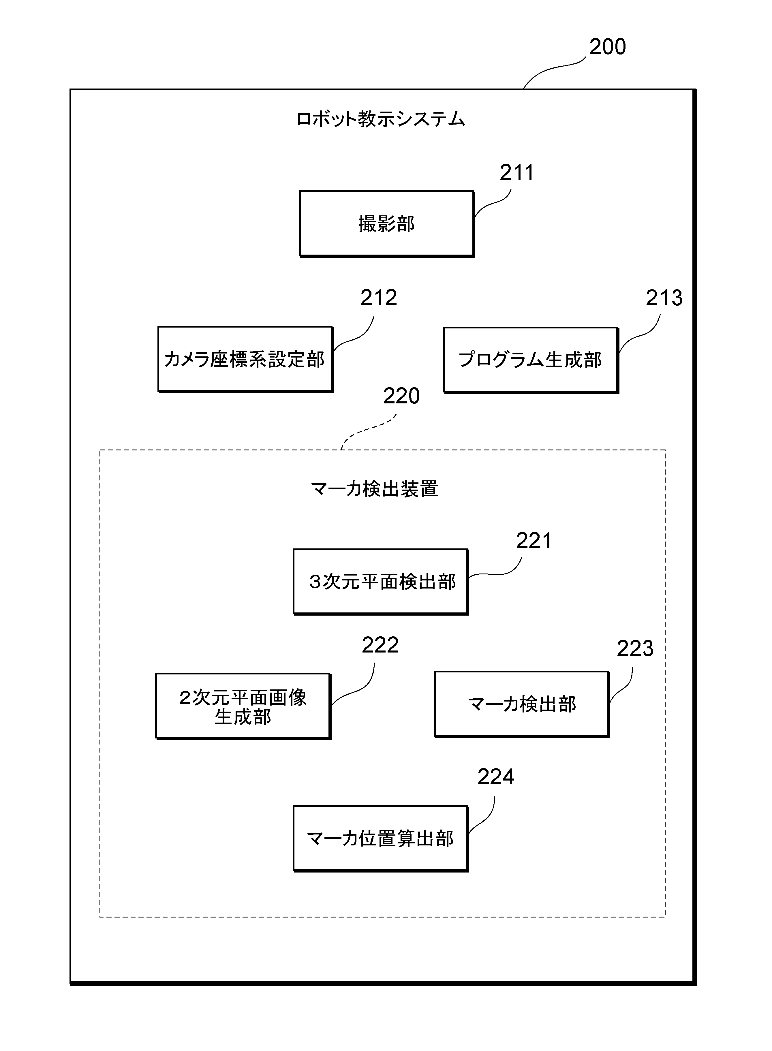
図2は、本発明の一実施形態に係るロボット教示システム200の機能的な構成を例示する図である。図2に示されるように、ロボット教示システム200は、機能的な構成として、例えば、撮影部211と、カメラ座標系設定部212と、プログラム生成部213とを有し、さらに、カメラ座標系を設定するための基準となるマーカを検出するためのマーカ検出装置220を含む。なお、マーカ検出装置220は、3次元平面検出部221と、2次元平面画像生成部222と、マーカ検出部223と、マーカ位置算出部224とを含む。
[Configuration of robot teaching system]
FIG. 2 is a diagram illustrating the functional configuration of a
これらの機能のうち、撮影部211は、撮影端末1が有する機能である。他方、カメラ座標系設定部212、プログラム生成部213、及びマーカ検出装置220における各部は、撮影端末1及びロボット制御装置2のどちらかが全てを備えてもよいし、撮影端末1及びロボット制御装置2に各機能を分散して備えてもよい。また、撮影端末1及びロボット制御装置2以外の他の装置が、上記機能の一部又は全部を備えてもよい。
Among these functions, the
撮影部211は、撮影端末1の撮影部12と同じであり、3Dカメラの機能として、点群データを取得する。なお、撮影部211は、少なくともマーカ及び溶接対象となるワークが含まれる点群データを取得する。
The
カメラ座標系設定部212は、撮影部211によって取得された点群データにより認識されるマーカに基づいてカメラ座標系を設定する。例えば、カメラ座標系設定部212は、撮影部211によって取得された点群データにより認識されるマーカの位置を原点として、当該原点で互いに直交するX軸、Y軸及びZ軸による三次元の直交座標系をカメラ座標系として設定する。
A camera coordinate
図3は、マーカMが溶接対象であるワークWに設定されており、当該マーカMの位置を原点Oとしてカメラ座標系が設定される様子を示す図である。図3に示されるように、マーカMは、ワークWの底板に設定されており、カメラ座標系設定部212は、撮影部211によって取得された点群データにより認識されるマーカMの位置を原点Oとして、当該原点Oで互いに直交するX軸、Y軸及びZ軸による三次元の直交座標系をカメラ座標系として設定している。なお、原点Oは、マーカMのうち任意の点を設定する。例えば、原点Oとして、マーカMのうち、予め決められた一点、中心点、又は選択された一点等が設定されればよい。
FIG. 3 is a diagram showing how a marker M is set on a workpiece W to be welded, and a camera coordinate system is set with the position of the marker M as an origin O. As shown in FIG. As shown in FIG. 3, the marker M is set on the bottom plate of the workpiece W, and the camera coordinate
マーカMは、空間内に置かれていることを撮影部211に認識させることができる識別子であればよい。マーカとして、例えばARマーカを用いることが好ましい。ARマーカを用いることで、空間内に置かれたARマーカを認識したときに、そのARマーカを原点とするカメラ座標系を、実際に取得された点群データに表示させることが簡易に実現できるようになる。なお、マーカMを検出するマーカ検出装置220の処理についての詳細は後述する。
The marker M may be an identifier that allows the
カメラ座標系設定部212によって設定されたカメラ座標系において、撮影部211によって取得された点群データから認識されるワークWの溶接位置L1,L2,L3に基づいてマニピュレータ3の動作経路を設定する。例えば、撮影部211によって取得された点群データから溶接位置L1,L2,L3が認識され、マニピュレータ3の先端に取り付けられた溶接トーチ32がワークWの溶接位置L1,L2,L3に沿って動作するように、マニピュレータ3(溶接トーチ32)の動作経路をユーザが手動で選択したり、当該溶接位置L1,L2,L3と溶接トーチ32との距離を算出して自動的に設定したりする。
In the camera coordinate system set by the camera coordinate
一方、ロボット制御装置2は、当該ロボット制御装置2が制御するマニピュレータ3の各軸の角度に関する情報等から当該マニピュレータ3の位置姿勢を把握する(ロボット座標系)。そして、マーカMの設置位置と、当該マーカMの設置位置に対するマニピュレータ3の位置姿勢(設置位置)とに基づいて、カメラ座標系とロボット座標系とを一致させるためのキャリブレーションを行うことができる。当該キャリブレーションは、例えば、マーカMの設置位置にマニピュレータ3(溶接トーチ32)の先端を合わせることにより行えばよい。
On the other hand, the
プログラム生成部213は、カメラ座標系において設定されたマニピュレータ3の動作経路を、カメラ座標系からロボット制御装置2に設定されているロボット座標系に変換しつつ、マニピュレータ3を動作させるための作業プログラムを生成する。
The
このように、ロボット教示システム200では、撮影部211で取得した点群データから認識されるマーカMを基準にカメラ座標系を設定し、当該カメラ座標系における溶接位置L1,L2,L3及びマニピュレータ3の動作経路をロボット座標系に変換しつつ、マニピュレータ3が適切に溶接位置L1,L2,L3に溶接する作業プログラムを生成している。そして、当該作業プログラムは、ロボット制御装置2における記憶部に記憶され、当該ロボット制御装置2は、作業プログラムに基づいてマニピュレータ3の動作を制御し、これにより、溶接ロボットシステム100として、ワークWの溶接位置L1,L2,L3に適切に溶接することができる。
As described above, in the
[マーカ検出装置220における処理の詳細]
上述したように、マーカMの位置を原点Oとしてカメラ座標系が設定されることから、当該マーカMの位置を適切に検出することが重要となる。以下、マーカMの位置を検出するマーカ検出装置220の処理について詳しく説明する。
[Details of Processing in Marker Detection Device 220]
As described above, since the camera coordinate system is set with the position of the marker M as the origin O, it is important to detect the position of the marker M appropriately. The processing of the
図4は、ワークWに設定されたマーカMの位置を検出するマーカ検出装置220における具体的な処理の様子を模式的に示す図である。図4に示されるように、マーカ検出装置220は、3Dカメラによって取得された点群データに基づいて、マーカMの位置を検出している。
FIG. 4 is a diagram schematically showing specific processing in the
図4(a)に示されるように、3Dカメラによって取得された点群データが描画されている。例えば、撮影部211は、公知のステレオ法による三次元計測手法を用いて取得した座標データ、又は距離計測センサ等により3Dスキャンして取得した座標データを、点群データとして取得する。
As shown in FIG. 4(a), the point cloud data acquired by the 3D camera is drawn. For example, the
3次元平面検出部221は、3Dカメラによって取得された点群データに基づいて、3次元空間における平面である3次元平面を検出する(図4(b))。例えば、3次元平面検出部221は、撮影部211によって取得された点群データに基づいて、所定の面積以上の平面を3次元平面として、ワークWを構成する底板である平面Wa及び背板である平面Wbを検出している。
The 3D
2次元平面画像生成部222は、3次元平面検出部221によって検出された3次元平面を構成する点群データを、2次元平面に射影することにより2次元平面画像を生成する(図4(c)(d))。例えば、3次元平面検出部221によって検出された平面Waについて、2次元平面に射影するとは、3次元座標値(X,Y,Z)の位置で示される各点群データを、当該平面Waを基準とする垂直方向に、当該平面Waと交差する位置に移動させて、2次元平面画像を生成することを含む。各点群データの3次元座標値(X,Y,Z)及び(R,G,B)で示される色情報は、平面Waの平面の方程式に基づいて2次元平面画像のピクセル情報(XY座標値及び色情報)として対応付けられて変換されることになる。これにより、図4(d)に示されるように、2次元平面画像生成部222は、2次元平面画像Wa2を生成する。この時、点群データの粒度が粗い場合には、2次元平面画像生成部222は、所定の画像処理(例えば、ガウスぼかし等の平滑化処理や画素補間処理等)を行うことにより2次元平面画像Wa2を生成してもよい。
The two-dimensional plane
マーカ検出部223は、2次元平面画像生成部222によって生成された2次元平面画像Wa2からマーカMを検出する(図4(e))。例えば、マーカ検出部223は、予め記憶されたマーカの画像とパターンマッチングを行うことにより、2次元平面画像生成部222によって生成された2次元平面画像Wa2からマーカMを検出する。
The
マーカ位置算出部224は、マーカ検出部223によって検出された2次元平面画像Wa2に含まれるマーカMについて、3次元平面検出部221によって3次元平面として検出された平面Waにおける3次元座標を算出する(図4(f))。図4(c)及び(d)を用いて説明したように、平面Waを構成する点群データの3次元座標値(X,Y,Z)を、当該平面Waを基準とする垂直方向に、当該平面Waと交差する位置に移動させて、2次元平面画像Wa2を生成したが、その逆の処理を行う。すなわち、2次元平面画像Wa2に含まれるマーカMの位置情報を、3次元平面である平面Wa上における3次元座標値(X,Y,Z)に変換する。
The
このように、マーカ検出装置220は、平面Wa上に設定されているマーカMの位置を適切に検出している。
Thus, the
[マーカ検出方法]
次に、本発明の一実施形態に係るマーカ検出装置220がマーカを検出する方法について、具体的に詳しく説明する。
[Marker detection method]
Next, a method for detecting markers by the
図5は、本発明の一実施形態に係るマーカ検出装置220が実行するマーカ検出方法M100の処理の流れを示すフローチャートである。図5に示されるように、マーカ検出方法M100は、ステップS110~S140を含み、各ステップは、マーカ検出装置220に含まれるプロセッサによって実行される。
FIG. 5 is a flow chart showing the flow of processing of the marker detection method M100 executed by the
ステップS110では、マーカ検出装置220は、3Dカメラによって取得された点群データに基づいて、3次元空間における平面である3次元平面を検出する(3次元平面検出ステップ)。具体例としては、マーカ検出装置220における3次元平面検出部221は、所定の面積以上の平面として、ワークWを構成する平面Wa及びWb等を検出する。
In step S110, the
ステップS120では、マーカ検出装置220は、ステップS110で検出された3次元平面を構成する点群データを、2次元平面に射影することにより2次元平面画像を生成する(2次元平面画像生成ステップ)。具体例としては、マーカ検出装置220における2次元平面画像生成部222は、ステップS110で検出された3次元平面Waについて、3次元座標値(X,Y,Z)の位置で示される各点群データを、当該平面Waを基準とする垂直方向に、当該平面Waと交差する位置に移動させて、2次元平面画像Wa2を生成する。
In step S120, the
ステップS130では、マーカ検出装置220は、ステップS120で生成された2次元平面画像からマーカMを検出する(マーカ検出ステップ)。具体例としては、マーカ検出装置220におけるマーカ検出部223は、予め記憶されたマーカの画像とパターンマッチングを行うことにより、2次元平面画像Wa2からマーカMを検出する。
At step S130, the
ステップS140では、マーカ検出装置220は、ステップS130で検出された2次元平面画像に含まれるマーカMについて、ステップS110で3次元平面として検出された平面における3次元座標を算出する(3次元座標算出ステップ)。具体例としては、マーカ検出装置220におけるマーカ位置算出部224は、2次元平面画像Wa2に含まれるマーカMの位置情報を、3次元平面である平面Wa上における3次元座標値(X,Y,Z)に変換する。
In step S140, the
以上のように、本発明の一実施形態に係るマーカ検出装置220及びマーカ検出方法M100によれば、3次元平面検出部221は、3Dカメラによって取得された点群データに基づいて、3次元空間における平面Wa及びWbを検出し、2次元平面画像生成部222は、当該平面Waを構成する点群データを当該平面Waを基準とする垂直方向に射影することにより2次元平面画像Wa2を生成する。そして、マーカ検出部223は、2次元平面画像Wa2からマーカMを検出し、マーカ位置算出部224は、2次元平面画像Wa2に含まれるマーカMについて、3次元平面Waにおける3次元座標値(X,Y,Z)を算出する。これにより、平面に設定されたマーカMの位置を適切に検出することができ、煩雑なカメラパラメータの設定をしなくても、平面に設定されたマーカMの位置を簡易に検出することができる。
As described above, according to the
さらに、本発明の一実施形態に係るマーカ検出装置220を用いたロボット教示システム200によれば、当該マーカ検出装置220によって適切に検出されたマーカMの位置に基づいて、カメラ座標系設定部212は、当該マーカMの位置を原点Oとしてカメラ座標系を設定する。プログラム生成部213は、マーカMの設置位置に基づいて、カメラ座標系において設定されたマニピュレータ3の動作経路を、カメラ座標系からロボット制御装置2に設定されているロボット座標系に変換しつつ、マニピュレータ3を動作させるための作業プログラムを生成する。これにより、適切な溶接位置に、より簡易に溶接することができる。
Furthermore, according to the
なお、本実施形態では、マーカ検出部223は、3次元平面検出部221によって検出された3次元平面Wa及びWbのうち、平面WaついてマーカMを検出した。複数の平面のうち、どの平面にマーカが含まれているか、例えば、ユーザが選択するようにしても構わないし、複数の平面のうち、1平面毎にマーカを検出するようにしても構わない。
Note that, in the present embodiment, the
実際に、ユーザが、マーカMが設定されている平面を把握していれば、当該平面を選択することにより、マーカ検出部223は、効率よく、マーカMを検出することができる。
Actually, if the user knows the plane on which the marker M is set, the
一方で、例えば、複数の平面のうち、1平面毎にマーカを検出するようにすれば、着実に処理を進めることにより、自動的にマーカMを検出することができる。ここで、複数の平面について、どのような順番でマーカを検出するかについては、例えば、面積の大きい順や視野中心から近い順、又はそれらの組み合わせ順で、処理するようにしても構わない。 On the other hand, for example, if the marker is detected for each plane among a plurality of planes, the marker M can be automatically detected by steadily advancing the process. Here, regarding the order in which markers are detected for a plurality of planes, for example, processing may be performed in descending order of area, in order of proximity from the center of the field of view, or in order of a combination thereof.
3次元平面検出部221によって検出された複数の平面のうち、面積の大きい平面や視野中心から近い平面に、マーカMが設定されている可能性が高いと考えられ、複数の平面のうち、1平面毎にマーカを検出する中で、早い段階でマーカを検出することが期待できる。これにより、演算処理の軽減及び処理時間の短縮に繋がる。
Among the plurality of planes detected by the three-dimensional
さらに、複数の平面について、どのような順番でマーカを検出するかについては、効率よくマーカを検出できる順であれば、これらの順に限定されるものではない。 Further, the order in which the markers are detected on the plurality of planes is not limited to the order as long as the markers can be detected efficiently.
具体例としては、所定の色(例えば、赤色等)で構成されたマーカ、又は所定の色を多く含むように構成されたマーカを用いる。そして、3次元平面検出部221によって複数の平面が検出された際に、当該複数の平面について、当該所定の色を多く含む順で処理するようにすればよい。複数の平面について、各平面を構成する点群データには、(R,G,B)で示される色情報が含まれており、当該色情報に基づいて、各平面に含まれる所定の色情報の割合を判定することができる。
As a specific example, a marker configured with a predetermined color (for example, red) or a marker configured to include many predetermined colors is used. Then, when a plurality of planes are detected by the three-dimensional
このように、マーカを所定の色を用いて構成させることにより、3次元平面検出部221によって複数の平面が検出された場合、マーカが含まれている平面を効率よく検出することができる。これにより、演算処理の軽減及び処理時間の短縮に繋がる。
In this way, by configuring the markers using predetermined colors, when a plurality of planes are detected by the three-dimensional
また、本実施形態では、溶接ロボットシステム100のロボット教示システム200に用いられるマーカ検出装置220を一例に挙げて説明したが、マーカ検出装置220が用いられる産業用ロボットは、溶接ロボットシステム100に限定されるものではない。例えば、電子部品及び機械部品の組み立てや搬送等を行う組み立てロボットシステムや搬送ロボットシステム等に、マーカ検出装置220を適用することもできる。
Further, in the present embodiment, the
以上説明した実施形態は、本発明の理解を容易にするためのものであり、本発明を限定して解釈するためのものではない。実施形態が備える各要素並びにその配置、材料、条件、形状及びサイズ等は、例示したものに限定されるわけではなく適宜変更することができる。また、異なる実施形態で示した構成同士を部分的に置換し又は組み合わせることが可能である。 The embodiments described above are for facilitating understanding of the present invention, and are not intended to limit and interpret the present invention. Each element included in the embodiment and its arrangement, materials, conditions, shape, size, etc. are not limited to those illustrated and can be changed as appropriate. Also, it is possible to partially replace or combine the configurations shown in different embodiments.
1…撮影端末、2…ロボット制御装置、3…マニピュレータ、11…制御部、12…撮影部、13…通信部、14…表示部、21…制御部、22…記憶部、23…通信部、24…溶接電源部、31…多関節アーム、32…溶接トーチ、100…溶接ロボットシステム、200…ロボット教示システム、211…撮影部、212…カメラ座標系設定部、213…プログラム生成部、220…マーカ検出装置、221…3次元平面検出部、222…2次元平面画像生成部、223…マーカ検出部、224…マーカ位置算出部、C…通信ケーブル、N…ネットワーク、M…マーカ、W…ワーク、L1~L3…溶接位置、Wa,Wb…平面、Wa2…平面画像、M100…マーカ検出方法、S110~S140…マーカ検出方法M100の各ステップ
DESCRIPTION OF
Claims (5)
前記検出された3次元平面を構成する点群データを、当該3次元平面を基準とする垂直方向に射影することにより2次元平面画像を生成する2次元平面画像生成部と、
前記生成された2次元平面画像からマーカを検出するマーカ検出部と、
前記検出された2次元平面画像に含まれるマーカについて、前記3次元平面における3次元座標を算出するマーカ位置算出部と、を備える、
マーカ検出装置。 a three-dimensional plane detection unit that detects a three-dimensional plane, which is a plane in a three-dimensional space, based on the point cloud data acquired by the 3D camera;
a two-dimensional plane image generating unit for generating a two-dimensional plane image by projecting the point cloud data constituting the detected three-dimensional plane in a vertical direction with respect to the three-dimensional plane;
a marker detection unit that detects a marker from the generated two-dimensional plane image;
a marker position calculator that calculates three-dimensional coordinates on the three-dimensional plane for markers included in the detected two-dimensional plane image;
Marker detector.
請求項1に記載のマーカ検出装置。 When the three-dimensional plane detection unit detects a plurality of three-dimensional planes, the marker detection unit detects a marker for each plane.
The marker detection device according to claim 1.
請求項2に記載のマーカ検出装置。 The marker detection unit detects the markers in order of area from the plurality of three-dimensional planes,
The marker detection device according to claim 2.
請求項2に記載のマーカ検出装置。 The marker detection unit detects the markers in order of center of field of view among the plurality of three-dimensional planes.
The marker detection device according to claim 2.
前記3Dカメラによって取得された点群データに基づいて、3次元空間における平面である3次元平面を検出する3次元平面検出部と、
前記検出された3次元平面を構成する点群データを、当該3次元平面を基準とする垂直方向に射影することにより2次元平面画像を生成する2次元平面画像生成部と、
前記生成された2次元平面画像からマーカを検出するマーカ検出部と、
前記検出された2次元平面画像に含まれるマーカについて、前記3次元平面における3次元座標を算出するマーカ位置算出部と、
前記算出されたマーカの3次元座標に基づいてカメラ座標系を設定するカメラ座標系設定部と、
前記カメラ座標系におけるマニピュレータの動作経路をロボット制御装置に設定されているロボット座標系に変換しつつ、当該マニピュレータを動作させるための作業プログラムを生成するプログラム生成部と、を備える、
ロボット教示システム。 a photographing unit having a 3D camera for photographing an image including the workpiece and the marker;
a three-dimensional plane detection unit that detects a three-dimensional plane that is a plane in a three-dimensional space based on the point cloud data acquired by the 3D camera;
a two-dimensional plane image generating unit for generating a two-dimensional plane image by projecting the point cloud data constituting the detected three-dimensional plane in a vertical direction with respect to the three-dimensional plane;
a marker detection unit that detects a marker from the generated two-dimensional plane image;
a marker position calculator that calculates three-dimensional coordinates on the three-dimensional plane for markers included in the detected two-dimensional plane image;
a camera coordinate system setting unit that sets a camera coordinate system based on the calculated three-dimensional coordinates of the marker;
a program generation unit that generates a work program for operating the manipulator while converting the motion path of the manipulator in the camera coordinate system to the robot coordinate system set in the robot control device;
robot teaching system.
Priority Applications (6)
| Application Number | Priority Date | Filing Date | Title |
|---|---|---|---|
| JP2021181014A JP7177239B1 (en) | 2021-11-05 | 2021-11-05 | Marker detection device and robot teaching system |
| KR1020220107502A KR20230065879A (en) | 2021-11-05 | 2022-08-26 | Marker detecting device and robot teaching system |
| EP22192377.4A EP4177838B1 (en) | 2021-11-05 | 2022-08-26 | Marker detection apparatus and robot teaching system |
| US17/897,420 US12508704B2 (en) | 2021-11-05 | 2022-08-29 | Marker detection apparatus and robot teaching system |
| CN202211075940.8A CN116086311B (en) | 2021-11-05 | 2022-09-02 | Mark detection device and robot teaching system |
| TW111133907A TWI806762B (en) | 2021-11-05 | 2022-09-07 | Mark detection device and robot teaching system |
Applications Claiming Priority (1)
| Application Number | Priority Date | Filing Date | Title |
|---|---|---|---|
| JP2021181014A JP7177239B1 (en) | 2021-11-05 | 2021-11-05 | Marker detection device and robot teaching system |
Publications (2)
| Publication Number | Publication Date |
|---|---|
| JP7177239B1 true JP7177239B1 (en) | 2022-11-22 |
| JP2023069265A JP2023069265A (en) | 2023-05-18 |
Family
ID=83081915
Family Applications (1)
| Application Number | Title | Priority Date | Filing Date |
|---|---|---|---|
| JP2021181014A Active JP7177239B1 (en) | 2021-11-05 | 2021-11-05 | Marker detection device and robot teaching system |
Country Status (6)
| Country | Link |
|---|---|
| US (1) | US12508704B2 (en) |
| EP (1) | EP4177838B1 (en) |
| JP (1) | JP7177239B1 (en) |
| KR (1) | KR20230065879A (en) |
| CN (1) | CN116086311B (en) |
| TW (1) | TWI806762B (en) |
Cited By (1)
| Publication number | Priority date | Publication date | Assignee | Title |
|---|---|---|---|---|
| CN115900828A (en) * | 2022-12-19 | 2023-04-04 | 中国工程物理研究院材料研究所 | Method and system for finely detecting surface state of revolving body component |
Families Citing this family (2)
| Publication number | Priority date | Publication date | Assignee | Title |
|---|---|---|---|---|
| JP7423851B1 (en) * | 2023-10-31 | 2024-01-29 | 株式会社ダイヘン | terminal device |
| JP7835824B1 (en) * | 2024-11-01 | 2026-03-25 | 株式会社ダイヘン | robot systems |
Citations (2)
| Publication number | Priority date | Publication date | Assignee | Title |
|---|---|---|---|---|
| JP2013131171A (en) | 2011-12-22 | 2013-07-04 | Univ Of Tokyo | Model generation device, model generation method, and model generation program |
| JP2016176816A (en) | 2015-03-20 | 2016-10-06 | キヤノン株式会社 | Image processing apparatus, image processing method, and program |
Family Cites Families (16)
| Publication number | Priority date | Publication date | Assignee | Title |
|---|---|---|---|---|
| CN101339654A (en) * | 2007-07-04 | 2009-01-07 | 北京威亚视讯科技有限公司 | Reinforced real environment three-dimensional registering method and system based on mark point |
| JP4762369B2 (en) * | 2009-12-08 | 2011-08-31 | パナソニック株式会社 | Image processing device |
| US20130329068A1 (en) * | 2012-06-08 | 2013-12-12 | Canon Kabushiki Kaisha | Image processing apparatus and image processing method |
| WO2013187204A1 (en) * | 2012-06-13 | 2013-12-19 | 株式会社島精機製作所 | Synthesis-parameter generation device for three-dimensional measurement apparatus |
| JP2015056057A (en) * | 2013-09-12 | 2015-03-23 | トヨタ自動車株式会社 | Method of estimating posture and robot |
| JP6415190B2 (en) * | 2014-09-03 | 2018-10-31 | キヤノン株式会社 | ROBOT DEVICE, ROBOT CONTROL PROGRAM, RECORDING MEDIUM, AND ROBOT DEVICE CONTROL METHOD |
| JP2016110215A (en) * | 2014-12-02 | 2016-06-20 | トヨタ自動車株式会社 | Marker recognition device, marker recognition method and recognition program |
| US11042146B2 (en) * | 2017-11-17 | 2021-06-22 | Kodak Alaris Inc. | Automated 360-degree dense point object inspection |
| CN109509143A (en) * | 2018-10-31 | 2019-03-22 | 太原理工大学 | A kind of method of three-dimensional point cloud conversion two dimensional image |
| US12036663B2 (en) * | 2019-03-25 | 2024-07-16 | Abb Schweiz Ag | Method and control arrangement for determining a relation between a robot coordinate system and a movable apparatus coordinate system |
| JP7281662B2 (en) * | 2019-10-11 | 2023-05-26 | パナソニックIpマネジメント株式会社 | Welding method, identification code assigning device and welded product |
| JP7359633B2 (en) * | 2019-10-17 | 2023-10-11 | ファナック株式会社 | robot system |
| CN110749290B (en) * | 2019-10-30 | 2021-06-01 | 易思维(杭州)科技有限公司 | Three-dimensional projection-based characteristic information rapid positioning method |
| JP2021085751A (en) * | 2019-11-27 | 2021-06-03 | 倉敷紡績株式会社 | Method for determining work position, method for controlling robot, work position determination device, and robot control system |
| EP4203477A4 (en) * | 2020-09-03 | 2024-02-28 | Sony Group Corporation | IMAGE PROCESSING APPARATUS AND METHOD |
| US12026897B2 (en) * | 2020-12-31 | 2024-07-02 | Imec Vzw | Augmented reality system, an augmented reality HMD, an augmented reality method and a computer program |
-
2021
- 2021-11-05 JP JP2021181014A patent/JP7177239B1/en active Active
-
2022
- 2022-08-26 KR KR1020220107502A patent/KR20230065879A/en active Pending
- 2022-08-26 EP EP22192377.4A patent/EP4177838B1/en active Active
- 2022-08-29 US US17/897,420 patent/US12508704B2/en active Active
- 2022-09-02 CN CN202211075940.8A patent/CN116086311B/en active Active
- 2022-09-07 TW TW111133907A patent/TWI806762B/en active
Patent Citations (2)
| Publication number | Priority date | Publication date | Assignee | Title |
|---|---|---|---|---|
| JP2013131171A (en) | 2011-12-22 | 2013-07-04 | Univ Of Tokyo | Model generation device, model generation method, and model generation program |
| JP2016176816A (en) | 2015-03-20 | 2016-10-06 | キヤノン株式会社 | Image processing apparatus, image processing method, and program |
Cited By (1)
| Publication number | Priority date | Publication date | Assignee | Title |
|---|---|---|---|---|
| CN115900828A (en) * | 2022-12-19 | 2023-04-04 | 中国工程物理研究院材料研究所 | Method and system for finely detecting surface state of revolving body component |
Also Published As
| Publication number | Publication date |
|---|---|
| EP4177838B1 (en) | 2025-08-06 |
| US12508704B2 (en) | 2025-12-30 |
| TWI806762B (en) | 2023-06-21 |
| US20230143710A1 (en) | 2023-05-11 |
| JP2023069265A (en) | 2023-05-18 |
| EP4177838A1 (en) | 2023-05-10 |
| KR20230065879A (en) | 2023-05-12 |
| CN116086311A (en) | 2023-05-09 |
| CN116086311B (en) | 2026-04-28 |
| TW202319196A (en) | 2023-05-16 |
Similar Documents
| Publication | Publication Date | Title |
|---|---|---|
| JP7190552B1 (en) | Robot teaching system | |
| JP7177239B1 (en) | Marker detection device and robot teaching system | |
| JP7183372B1 (en) | Marker detection device and robot teaching system | |
| US12600040B2 (en) | Simulation device using three-dimensional position information obtained from output from vision sensor | |
| JP7176148B1 (en) | Weld line detection system | |
| JP7250489B2 (en) | Image processing device, its control method, and program | |
| TWI889281B (en) | Terminal device | |
| US20230398687A1 (en) | Method for generating movement route of robot, movement route generation apparatus, robot system, and program | |
| JP7774421B2 (en) | Coordinate system transformation system and coordinate system transformation method | |
| EP4166267B1 (en) | Welding line detection system | |
| JP7195476B1 (en) | WORK PROGRAM CREATION SYSTEM AND WORK PROGRAM CREATION METHOD | |
| JP7835824B1 (en) | robot systems | |
| US20260124745A1 (en) | Robot system | |
| JP2026061689A (en) | Robot system | |
| CN121989222A (en) | Robotic systems | |
| JP2024013243A (en) | Point cloud data synthesis device, point cloud data synthesis program, point cloud data synthesis method, and point cloud data synthesis system |
Legal Events
| Date | Code | Title | Description |
|---|---|---|---|
| A621 | Written request for application examination |
Free format text: JAPANESE INTERMEDIATE CODE: A621 Effective date: 20221017 |
|
| A871 | Explanation of circumstances concerning accelerated examination |
Free format text: JAPANESE INTERMEDIATE CODE: A871 Effective date: 20221017 |
|
| TRDD | Decision of grant or rejection written | ||
| A01 | Written decision to grant a patent or to grant a registration (utility model) |
Free format text: JAPANESE INTERMEDIATE CODE: A01 Effective date: 20221028 |
|
| A61 | First payment of annual fees (during grant procedure) |
Free format text: JAPANESE INTERMEDIATE CODE: A61 Effective date: 20221110 |
|
| R150 | Certificate of patent or registration of utility model |
Ref document number: 7177239 Country of ref document: JP Free format text: JAPANESE INTERMEDIATE CODE: R150 |
|
| R250 | Receipt of annual fees |
Free format text: JAPANESE INTERMEDIATE CODE: R250 |