JP7163595B2 - 3D object manufacturing method and 3D object modeling apparatus - Google Patents
3D object manufacturing method and 3D object modeling apparatus Download PDFInfo
- Publication number
- JP7163595B2 JP7163595B2 JP2018045414A JP2018045414A JP7163595B2 JP 7163595 B2 JP7163595 B2 JP 7163595B2 JP 2018045414 A JP2018045414 A JP 2018045414A JP 2018045414 A JP2018045414 A JP 2018045414A JP 7163595 B2 JP7163595 B2 JP 7163595B2
- Authority
- JP
- Japan
- Prior art keywords
- modeling
- nozzle
- molding
- recess
- modeling table
- Prior art date
- Legal status (The legal status is an assumption and is not a legal conclusion. Google has not performed a legal analysis and makes no representation as to the accuracy of the status listed.)
- Active
Links
Images


Classifications
-
- B—PERFORMING OPERATIONS; TRANSPORTING
- B29—WORKING OF PLASTICS; WORKING OF SUBSTANCES IN A PLASTIC STATE IN GENERAL
- B29C—SHAPING OR JOINING OF PLASTICS; SHAPING OF MATERIAL IN A PLASTIC STATE, NOT OTHERWISE PROVIDED FOR; AFTER-TREATMENT OF THE SHAPED PRODUCTS, e.g. REPAIRING
- B29C64/00—Additive manufacturing, i.e. manufacturing of three-dimensional [3D] objects by additive deposition, additive agglomeration or additive layering, e.g. by 3D printing, stereolithography or selective laser sintering
- B29C64/20—Apparatus for additive manufacturing; Details thereof or accessories therefor
- B29C64/227—Driving means
- B29C64/241—Driving means for rotary motion
-
- B—PERFORMING OPERATIONS; TRANSPORTING
- B22—CASTING; POWDER METALLURGY
- B22F—WORKING METALLIC POWDER; MANUFACTURE OF ARTICLES FROM METALLIC POWDER; MAKING METALLIC POWDER; APPARATUS OR DEVICES SPECIALLY ADAPTED FOR METALLIC POWDER
- B22F10/00—Additive manufacturing of workpieces or articles from metallic powder
- B22F10/10—Formation of a green body
- B22F10/18—Formation of a green body by mixing binder with metal in filament form, e.g. fused filament fabrication [FFF]
-
- B—PERFORMING OPERATIONS; TRANSPORTING
- B22—CASTING; POWDER METALLURGY
- B22F—WORKING METALLIC POWDER; MANUFACTURE OF ARTICLES FROM METALLIC POWDER; MAKING METALLIC POWDER; APPARATUS OR DEVICES SPECIALLY ADAPTED FOR METALLIC POWDER
- B22F10/00—Additive manufacturing of workpieces or articles from metallic powder
- B22F10/20—Direct sintering or melting
- B22F10/22—Direct deposition of molten metal
-
- B—PERFORMING OPERATIONS; TRANSPORTING
- B22—CASTING; POWDER METALLURGY
- B22F—WORKING METALLIC POWDER; MANUFACTURE OF ARTICLES FROM METALLIC POWDER; MAKING METALLIC POWDER; APPARATUS OR DEVICES SPECIALLY ADAPTED FOR METALLIC POWDER
- B22F12/00—Apparatus or devices specially adapted for additive manufacturing; Auxiliary means for additive manufacturing; Combinations of additive manufacturing apparatus or devices with other processing apparatus or devices
- B22F12/50—Means for feeding of material, e.g. heads
- B22F12/53—Nozzles
-
- B—PERFORMING OPERATIONS; TRANSPORTING
- B22—CASTING; POWDER METALLURGY
- B22F—WORKING METALLIC POWDER; MANUFACTURE OF ARTICLES FROM METALLIC POWDER; MAKING METALLIC POWDER; APPARATUS OR DEVICES SPECIALLY ADAPTED FOR METALLIC POWDER
- B22F12/00—Apparatus or devices specially adapted for additive manufacturing; Auxiliary means for additive manufacturing; Combinations of additive manufacturing apparatus or devices with other processing apparatus or devices
- B22F12/50—Means for feeding of material, e.g. heads
- B22F12/55—Two or more means for feeding material
-
- B—PERFORMING OPERATIONS; TRANSPORTING
- B29—WORKING OF PLASTICS; WORKING OF SUBSTANCES IN A PLASTIC STATE IN GENERAL
- B29C—SHAPING OR JOINING OF PLASTICS; SHAPING OF MATERIAL IN A PLASTIC STATE, NOT OTHERWISE PROVIDED FOR; AFTER-TREATMENT OF THE SHAPED PRODUCTS, e.g. REPAIRING
- B29C64/00—Additive manufacturing, i.e. manufacturing of three-dimensional [3D] objects by additive deposition, additive agglomeration or additive layering, e.g. by 3D printing, stereolithography or selective laser sintering
- B29C64/10—Processes of additive manufacturing
- B29C64/106—Processes of additive manufacturing using only liquids or viscous materials, e.g. depositing a continuous bead of viscous material
- B29C64/112—Processes of additive manufacturing using only liquids or viscous materials, e.g. depositing a continuous bead of viscous material using individual droplets, e.g. from jetting heads
-
- B—PERFORMING OPERATIONS; TRANSPORTING
- B29—WORKING OF PLASTICS; WORKING OF SUBSTANCES IN A PLASTIC STATE IN GENERAL
- B29C—SHAPING OR JOINING OF PLASTICS; SHAPING OF MATERIAL IN A PLASTIC STATE, NOT OTHERWISE PROVIDED FOR; AFTER-TREATMENT OF THE SHAPED PRODUCTS, e.g. REPAIRING
- B29C64/00—Additive manufacturing, i.e. manufacturing of three-dimensional [3D] objects by additive deposition, additive agglomeration or additive layering, e.g. by 3D printing, stereolithography or selective laser sintering
- B29C64/10—Processes of additive manufacturing
- B29C64/106—Processes of additive manufacturing using only liquids or viscous materials, e.g. depositing a continuous bead of viscous material
- B29C64/118—Processes of additive manufacturing using only liquids or viscous materials, e.g. depositing a continuous bead of viscous material using filamentary material being melted, e.g. fused deposition modelling [FDM]
-
- B—PERFORMING OPERATIONS; TRANSPORTING
- B29—WORKING OF PLASTICS; WORKING OF SUBSTANCES IN A PLASTIC STATE IN GENERAL
- B29C—SHAPING OR JOINING OF PLASTICS; SHAPING OF MATERIAL IN A PLASTIC STATE, NOT OTHERWISE PROVIDED FOR; AFTER-TREATMENT OF THE SHAPED PRODUCTS, e.g. REPAIRING
- B29C64/00—Additive manufacturing, i.e. manufacturing of three-dimensional [3D] objects by additive deposition, additive agglomeration or additive layering, e.g. by 3D printing, stereolithography or selective laser sintering
- B29C64/20—Apparatus for additive manufacturing; Details thereof or accessories therefor
- B29C64/205—Means for applying layers
- B29C64/209—Heads; Nozzles
-
- B—PERFORMING OPERATIONS; TRANSPORTING
- B29—WORKING OF PLASTICS; WORKING OF SUBSTANCES IN A PLASTIC STATE IN GENERAL
- B29C—SHAPING OR JOINING OF PLASTICS; SHAPING OF MATERIAL IN A PLASTIC STATE, NOT OTHERWISE PROVIDED FOR; AFTER-TREATMENT OF THE SHAPED PRODUCTS, e.g. REPAIRING
- B29C64/00—Additive manufacturing, i.e. manufacturing of three-dimensional [3D] objects by additive deposition, additive agglomeration or additive layering, e.g. by 3D printing, stereolithography or selective laser sintering
- B29C64/30—Auxiliary operations or equipment
- B29C64/386—Data acquisition or data processing for additive manufacturing
- B29C64/393—Data acquisition or data processing for additive manufacturing for controlling or regulating additive manufacturing processes
-
- B—PERFORMING OPERATIONS; TRANSPORTING
- B33—ADDITIVE MANUFACTURING TECHNOLOGY
- B33Y—ADDITIVE MANUFACTURING, i.e. MANUFACTURING OF THREE-DIMENSIONAL [3D] OBJECTS BY ADDITIVE DEPOSITION, ADDITIVE AGGLOMERATION OR ADDITIVE LAYERING, e.g. BY 3D PRINTING, STEREOLITHOGRAPHY OR SELECTIVE LASER SINTERING
- B33Y10/00—Processes of additive manufacturing
-
- B—PERFORMING OPERATIONS; TRANSPORTING
- B33—ADDITIVE MANUFACTURING TECHNOLOGY
- B33Y—ADDITIVE MANUFACTURING, i.e. MANUFACTURING OF THREE-DIMENSIONAL [3D] OBJECTS BY ADDITIVE DEPOSITION, ADDITIVE AGGLOMERATION OR ADDITIVE LAYERING, e.g. BY 3D PRINTING, STEREOLITHOGRAPHY OR SELECTIVE LASER SINTERING
- B33Y30/00—Apparatus for additive manufacturing; Details thereof or accessories therefor
-
- B—PERFORMING OPERATIONS; TRANSPORTING
- B33—ADDITIVE MANUFACTURING TECHNOLOGY
- B33Y—ADDITIVE MANUFACTURING, i.e. MANUFACTURING OF THREE-DIMENSIONAL [3D] OBJECTS BY ADDITIVE DEPOSITION, ADDITIVE AGGLOMERATION OR ADDITIVE LAYERING, e.g. BY 3D PRINTING, STEREOLITHOGRAPHY OR SELECTIVE LASER SINTERING
- B33Y40/00—Auxiliary operations or equipment, e.g. for material handling
-
- B—PERFORMING OPERATIONS; TRANSPORTING
- B33—ADDITIVE MANUFACTURING TECHNOLOGY
- B33Y—ADDITIVE MANUFACTURING, i.e. MANUFACTURING OF THREE-DIMENSIONAL [3D] OBJECTS BY ADDITIVE DEPOSITION, ADDITIVE AGGLOMERATION OR ADDITIVE LAYERING, e.g. BY 3D PRINTING, STEREOLITHOGRAPHY OR SELECTIVE LASER SINTERING
- B33Y50/00—Data acquisition or data processing for additive manufacturing
- B33Y50/02—Data acquisition or data processing for additive manufacturing for controlling or regulating additive manufacturing processes
-
- C—CHEMISTRY; METALLURGY
- C04—CEMENTS; CONCRETE; ARTIFICIAL STONE; CERAMICS; REFRACTORIES
- C04B—LIME, MAGNESIA; SLAG; CEMENTS; COMPOSITIONS THEREOF, e.g. MORTARS, CONCRETE OR LIKE BUILDING MATERIALS; ARTIFICIAL STONE; CERAMICS; REFRACTORIES; TREATMENT OF NATURAL STONE
- C04B35/00—Shaped ceramic products characterised by their composition; Ceramics compositions; Processing powders of inorganic compounds preparatory to the manufacturing of ceramic products
- C04B35/01—Shaped ceramic products characterised by their composition; Ceramics compositions; Processing powders of inorganic compounds preparatory to the manufacturing of ceramic products based on oxide ceramics
- C04B35/10—Shaped ceramic products characterised by their composition; Ceramics compositions; Processing powders of inorganic compounds preparatory to the manufacturing of ceramic products based on oxide ceramics based on aluminium oxide
- C04B35/111—Fine ceramics
-
- C—CHEMISTRY; METALLURGY
- C04—CEMENTS; CONCRETE; ARTIFICIAL STONE; CERAMICS; REFRACTORIES
- C04B—LIME, MAGNESIA; SLAG; CEMENTS; COMPOSITIONS THEREOF, e.g. MORTARS, CONCRETE OR LIKE BUILDING MATERIALS; ARTIFICIAL STONE; CERAMICS; REFRACTORIES; TREATMENT OF NATURAL STONE
- C04B35/00—Shaped ceramic products characterised by their composition; Ceramics compositions; Processing powders of inorganic compounds preparatory to the manufacturing of ceramic products
- C04B35/01—Shaped ceramic products characterised by their composition; Ceramics compositions; Processing powders of inorganic compounds preparatory to the manufacturing of ceramic products based on oxide ceramics
- C04B35/14—Shaped ceramic products characterised by their composition; Ceramics compositions; Processing powders of inorganic compounds preparatory to the manufacturing of ceramic products based on oxide ceramics based on silica
-
- C—CHEMISTRY; METALLURGY
- C04—CEMENTS; CONCRETE; ARTIFICIAL STONE; CERAMICS; REFRACTORIES
- C04B—LIME, MAGNESIA; SLAG; CEMENTS; COMPOSITIONS THEREOF, e.g. MORTARS, CONCRETE OR LIKE BUILDING MATERIALS; ARTIFICIAL STONE; CERAMICS; REFRACTORIES; TREATMENT OF NATURAL STONE
- C04B35/00—Shaped ceramic products characterised by their composition; Ceramics compositions; Processing powders of inorganic compounds preparatory to the manufacturing of ceramic products
- C04B35/01—Shaped ceramic products characterised by their composition; Ceramics compositions; Processing powders of inorganic compounds preparatory to the manufacturing of ceramic products based on oxide ceramics
- C04B35/46—Shaped ceramic products characterised by their composition; Ceramics compositions; Processing powders of inorganic compounds preparatory to the manufacturing of ceramic products based on oxide ceramics based on titanium oxides or titanates
-
- C—CHEMISTRY; METALLURGY
- C04—CEMENTS; CONCRETE; ARTIFICIAL STONE; CERAMICS; REFRACTORIES
- C04B—LIME, MAGNESIA; SLAG; CEMENTS; COMPOSITIONS THEREOF, e.g. MORTARS, CONCRETE OR LIKE BUILDING MATERIALS; ARTIFICIAL STONE; CERAMICS; REFRACTORIES; TREATMENT OF NATURAL STONE
- C04B35/00—Shaped ceramic products characterised by their composition; Ceramics compositions; Processing powders of inorganic compounds preparatory to the manufacturing of ceramic products
- C04B35/01—Shaped ceramic products characterised by their composition; Ceramics compositions; Processing powders of inorganic compounds preparatory to the manufacturing of ceramic products based on oxide ceramics
- C04B35/48—Shaped ceramic products characterised by their composition; Ceramics compositions; Processing powders of inorganic compounds preparatory to the manufacturing of ceramic products based on oxide ceramics based on zirconium or hafnium oxides, zirconates, zircon or hafnates
- C04B35/486—Fine ceramics
-
- C—CHEMISTRY; METALLURGY
- C04—CEMENTS; CONCRETE; ARTIFICIAL STONE; CERAMICS; REFRACTORIES
- C04B—LIME, MAGNESIA; SLAG; CEMENTS; COMPOSITIONS THEREOF, e.g. MORTARS, CONCRETE OR LIKE BUILDING MATERIALS; ARTIFICIAL STONE; CERAMICS; REFRACTORIES; TREATMENT OF NATURAL STONE
- C04B35/00—Shaped ceramic products characterised by their composition; Ceramics compositions; Processing powders of inorganic compounds preparatory to the manufacturing of ceramic products
- C04B35/515—Shaped ceramic products characterised by their composition; Ceramics compositions; Processing powders of inorganic compounds preparatory to the manufacturing of ceramic products based on non-oxide ceramics
- C04B35/58—Shaped ceramic products characterised by their composition; Ceramics compositions; Processing powders of inorganic compounds preparatory to the manufacturing of ceramic products based on non-oxide ceramics based on borides, nitrides, i.e. nitrides, oxynitrides, carbonitrides or oxycarbonitrides or silicides
- C04B35/581—Shaped ceramic products characterised by their composition; Ceramics compositions; Processing powders of inorganic compounds preparatory to the manufacturing of ceramic products based on non-oxide ceramics based on borides, nitrides, i.e. nitrides, oxynitrides, carbonitrides or oxycarbonitrides or silicides based on aluminium nitride
-
- C—CHEMISTRY; METALLURGY
- C04—CEMENTS; CONCRETE; ARTIFICIAL STONE; CERAMICS; REFRACTORIES
- C04B—LIME, MAGNESIA; SLAG; CEMENTS; COMPOSITIONS THEREOF, e.g. MORTARS, CONCRETE OR LIKE BUILDING MATERIALS; ARTIFICIAL STONE; CERAMICS; REFRACTORIES; TREATMENT OF NATURAL STONE
- C04B35/00—Shaped ceramic products characterised by their composition; Ceramics compositions; Processing powders of inorganic compounds preparatory to the manufacturing of ceramic products
- C04B35/622—Forming processes; Processing powders of inorganic compounds preparatory to the manufacturing of ceramic products
- C04B35/626—Preparing or treating the powders individually or as batches ; preparing or treating macroscopic reinforcing agents for ceramic products, e.g. fibres; mechanical aspects section B
- C04B35/63—Preparing or treating the powders individually or as batches ; preparing or treating macroscopic reinforcing agents for ceramic products, e.g. fibres; mechanical aspects section B using additives specially adapted for forming the products, e.g.. binder binders
- C04B35/632—Organic additives
- C04B35/634—Polymers
-
- B—PERFORMING OPERATIONS; TRANSPORTING
- B22—CASTING; POWDER METALLURGY
- B22F—WORKING METALLIC POWDER; MANUFACTURE OF ARTICLES FROM METALLIC POWDER; MAKING METALLIC POWDER; APPARATUS OR DEVICES SPECIALLY ADAPTED FOR METALLIC POWDER
- B22F1/00—Metallic powder; Treatment of metallic powder, e.g. to facilitate working or to improve properties
- B22F1/10—Metallic powder containing lubricating or binding agents; Metallic powder containing organic material
- B22F1/102—Metallic powder coated with organic material
-
- B—PERFORMING OPERATIONS; TRANSPORTING
- B22—CASTING; POWDER METALLURGY
- B22F—WORKING METALLIC POWDER; MANUFACTURE OF ARTICLES FROM METALLIC POWDER; MAKING METALLIC POWDER; APPARATUS OR DEVICES SPECIALLY ADAPTED FOR METALLIC POWDER
- B22F12/00—Apparatus or devices specially adapted for additive manufacturing; Auxiliary means for additive manufacturing; Combinations of additive manufacturing apparatus or devices with other processing apparatus or devices
- B22F12/10—Auxiliary heating means
-
- B—PERFORMING OPERATIONS; TRANSPORTING
- B22—CASTING; POWDER METALLURGY
- B22F—WORKING METALLIC POWDER; MANUFACTURE OF ARTICLES FROM METALLIC POWDER; MAKING METALLIC POWDER; APPARATUS OR DEVICES SPECIALLY ADAPTED FOR METALLIC POWDER
- B22F2999/00—Aspects linked to processes or compositions used in powder metallurgy
-
- C—CHEMISTRY; METALLURGY
- C04—CEMENTS; CONCRETE; ARTIFICIAL STONE; CERAMICS; REFRACTORIES
- C04B—LIME, MAGNESIA; SLAG; CEMENTS; COMPOSITIONS THEREOF, e.g. MORTARS, CONCRETE OR LIKE BUILDING MATERIALS; ARTIFICIAL STONE; CERAMICS; REFRACTORIES; TREATMENT OF NATURAL STONE
- C04B2235/00—Aspects relating to ceramic starting mixtures or sintered ceramic products
- C04B2235/60—Aspects relating to the preparation, properties or mechanical treatment of green bodies or pre-forms
- C04B2235/602—Making the green bodies or pre-forms by moulding
- C04B2235/6026—Computer aided shaping, e.g. rapid prototyping
-
- Y—GENERAL TAGGING OF NEW TECHNOLOGICAL DEVELOPMENTS; GENERAL TAGGING OF CROSS-SECTIONAL TECHNOLOGIES SPANNING OVER SEVERAL SECTIONS OF THE IPC; TECHNICAL SUBJECTS COVERED BY FORMER USPC CROSS-REFERENCE ART COLLECTIONS [XRACs] AND DIGESTS
- Y02—TECHNOLOGIES OR APPLICATIONS FOR MITIGATION OR ADAPTATION AGAINST CLIMATE CHANGE
- Y02P—CLIMATE CHANGE MITIGATION TECHNOLOGIES IN THE PRODUCTION OR PROCESSING OF GOODS
- Y02P10/00—Technologies related to metal processing
- Y02P10/25—Process efficiency
Landscapes
- Engineering & Computer Science (AREA)
- Chemical & Material Sciences (AREA)
- Materials Engineering (AREA)
- Manufacturing & Machinery (AREA)
- Ceramic Engineering (AREA)
- Mechanical Engineering (AREA)
- Physics & Mathematics (AREA)
- Optics & Photonics (AREA)
- Organic Chemistry (AREA)
- Structural Engineering (AREA)
- Composite Materials (AREA)
- Inorganic Chemistry (AREA)
- Producing Shaped Articles From Materials (AREA)
- Powder Metallurgy (AREA)
Description
本発明は、三次元造形物の製造技術に関する。 The present invention relates to technology for manufacturing three-dimensional structures.
例えば、下記の特許文献1には、インクジェット方式のヘッドから材料を吐出して硬化させることによって三次元造形物を造形する製造方法が開示されている。特許文献1の技術では、造形精度を高めつつ、迅速に三次元造形物を造形するために、三次元造形物の輪郭を決定する支持層を高い精度で造形し、精度を要しない構成層を支持層によって支持された状態で迅速に造形している。
For example,
上記の特許文献1では、流動性を有している状態で準備された材料をインクジェット方式で吐出する技術が開示されているにすぎない。特許文献1の技術では、固体の状態で準備された材料を用いて、より簡素な工程や構成により、高い造形精度で、迅速に三次元造形物を造形することについては考慮されていない。
本発明の第1の形態は、三次元造形物の製造方法であって;材料生成部によって材料の少なくとも一部を溶融させて造形材料を生成する可塑化工程と;造形テーブルとノズルとの相対位置を変えながら、前記造形テーブルに向かって、前記ノズルから前記造形材料を吐出する吐出処理によって、前記造形テーブルから前記ノズルに向かう方向に開口する凹部を有する第1造形部位を造形する第1工程と;前記吐出処理によって前記造形材料を前記凹部内に堆積させ、前記凹部内に固定される第2造形部位を、前記第1造形部位の単位体積あたりの造形時間よりも短い単位体積あたりの造形時間で造形する第2工程と;を備え、前記材料生成部は、溝が形成された溝形成面を有し、回転可能なフラットスクリューと、前記溝形成面に対向し、前記ノズルに連通する連通孔が形成されたスクリュー対面部と、を備え、前記フラットスクリューは、回転軸に沿った方向の長さが、前記回転軸に垂直な方向の長さよりも短く、前記第2工程では、前記吐出処理における前記造形テーブルに対する前記ノズルの移動速度を前記第1工程のときよりも低下させることによって、前記ノズルの下に前記造形材料が堆積される範囲を前記第1工程のときより増大させる、製造方法として提供される。
本発明の第2の形態は、三次元造形物の製造方法であって;材料生成部によって材料の少なくとも一部を溶融させて造形材料を生成する可塑化工程と;造形テーブルとノズルとの相対位置を変えながら、前記造形テーブルに向かって、前記ノズルから前記造形材料を吐出する吐出処理によって、前記造形テーブルから前記ノズルに向かう方向に開口する凹部を有する第1造形部位を造形する第1工程と;前記吐出処理によって前記造形材料を前記凹部内に堆積させ、前記凹部内に固定される第2造形部位を、前記第1造形部位の単位体積あたりの造形時間よりも短い単位体積あたりの造形時間で造形する第2工程と;を備え、前記材料生成部は、溝が形成された溝形成面を有し、回転可能なフラットスクリューと、前記溝形成面に対向し、前記ノズルに連通する連通孔が形成されたスクリュー対面部と、を備え、前記フラットスクリューは、回転軸に沿った方向の長さが、前記回転軸に垂直な方向の長さよりも短く、前記第1工程の前記吐出処理では、前記造形テーブルに対する前記ノズルの移動方向を変更するときに、前記ノズルからの前記造形材料の吐出量を低下させ、前記第2工程の前記吐出処理では、前記造形テーブルに対する前記ノズルの移動方向を変更するときに、前記ノズルからの前記造形材料の吐出量を前記第1工程のときよりも低下させない、製造方法として提供される。
本発明の第3の形態は、三次元造形物の製造方法であって;材料生成部によって材料の少なくとも一部を溶融させて造形材料を生成する可塑化工程と;造形テーブルとノズルとの相対位置を変えながら、前記造形テーブルに向かって、前記ノズルから前記造形材料を吐出する吐出処理によって、前記造形テーブルから前記ノズルに向かう方向に開口する凹部を有する第1造形部位を造形する第1工程と;前記吐出処理によって前記造形材料を前記凹部内に堆積させ、前記凹部内に固定される第2造形部位を、前記第1造形部位の単位体積あたりの造形時間よりも短い単位体積あたりの造形時間で造形する第2工程と;を備え、前記材料生成部は、溝が形成された溝形成面を有し、回転可能なフラットスクリューと、前記溝形成面に対向し、前記ノズルに連通する連通孔が形成されたスクリュー対面部と、を備え、前記フラットスクリューは、回転軸に沿った方向の長さが、前記回転軸に垂直な方向の長さよりも短く、前記第1工程の前記吐出処理では、前記ノズルとして第1ノズルを使用し、前記第2工程の前記吐出処理では、前記ノズルとして、前記第1ノズルよりも吐出口の孔径が大きい第2ノズルを使用する、製造方法として提供される。
A first aspect of the present invention is a method for manufacturing a three-dimensional structure, comprising; a plasticizing step of melting at least a portion of a material by a material generating unit to generate a modeling material; A first modeling part having a recess opening in a direction from the modeling table toward the nozzle is modeled by a discharge process of discharging the modeling material from the nozzle toward the modeling table while changing the position. depositing the modeling material in the recess by the dispensing process, and forming a second modeling portion fixed in the recess in a molding time per unit volume that is shorter than the modeling time per unit volume of the first modeling portion; and a second step of molding in a molding time of , wherein the material generation unit has a grooved surface on which grooves are formed, a rotatable flat screw, and a rotatable flat screw facing the grooved surface and facing the nozzle a screw-facing portion in which a communicating hole is formed, wherein the length of the flat screw in the direction along the rotation axis is shorter than the length in the direction perpendicular to the rotation axis, and in the second step and increasing the range in which the modeling material is deposited under the nozzle from that in the first step by lowering the moving speed of the nozzle relative to the modeling table in the discharge process than in the first step. provided as a manufacturing method.
A second aspect of the present invention is a method for manufacturing a three-dimensional structure, comprising; a plasticizing step of melting at least a portion of a material by a material generating section to generate a modeling material; A first step of modeling a first modeling portion having a recess opening in a direction from the modeling table toward the nozzle by an ejection process of ejecting the modeling material from the nozzle toward the modeling table while changing the position. and; depositing the modeling material in the recess by the dispensing process, and forming a second modeling portion fixed in the recess in a molding time per unit volume that is shorter than the modeling time per unit volume of the first modeling portion. a second step of shaping in time, wherein the material generator has a grooved surface in which grooves are formed, a rotatable flat screw and a rotatable flat screw facing the grooved surface and communicating with the nozzle; a screw facing portion having a communication hole formed therein, wherein the flat screw has a length in a direction along the rotation axis shorter than a length in a direction perpendicular to the rotation axis, and the discharge in the first step In the process, when changing the moving direction of the nozzle with respect to the modeling table, the discharge amount of the modeling material from the nozzle is reduced, and in the discharge process of the second step, the nozzle is moved with respect to the modeling table. A manufacturing method is provided in which, when the direction is changed, the discharge amount of the modeling material from the nozzle does not decrease as compared with that in the first step.
A third aspect of the present invention is a method for manufacturing a three-dimensional structure, comprising; a plasticizing step of melting at least a portion of a material by a material generating section to generate a modeling material; A first step of modeling a first modeling portion having a recess opening in a direction from the modeling table toward the nozzle by an ejection process of ejecting the modeling material from the nozzle toward the modeling table while changing the position. and; depositing the modeling material in the recess by the dispensing process, and forming a second modeling portion fixed in the recess in a molding time per unit volume that is shorter than the modeling time per unit volume of the first modeling portion. a second step of shaping in time, wherein the material generator has a grooved surface in which grooves are formed, a rotatable flat screw and a rotatable flat screw facing the grooved surface and communicating with the nozzle; a screw facing portion having a communication hole formed therein, wherein the flat screw has a length in a direction along the rotation axis shorter than a length in a direction perpendicular to the rotation axis, and the discharge in the first step In the process, a first nozzle is used as the nozzle, and in the ejection process of the second step, a second nozzle having an ejection port hole diameter larger than that of the first nozzle is used as the nozzle. be done.
1.第1実施形態:
図1は、第1実施形態における三次元造形物の製造方法を実行する三次元造形装置100の構成を示す概略図である。図1には、互いに直交するX,Y,Z方向を示す矢印が示されている。第1実施形態では、X方向およびY方向は、水平面に平行な方向であり、Z方向は、重力方向(鉛直方向)とは反対の方向である。X,Y,Z方向を示す矢印は、他の参照図においても、図示の方向が図1と対応するように適宜、図示してある。
1. First embodiment:
FIG. 1 is a schematic diagram showing the configuration of a three-
三次元造形装置100は、造形材料を堆積させることによって三次元造形物を造形する。以下では、「三次元造形装置」を単に「造形装置」とも呼び、三次元造形物を単に「造形物」とも呼ぶ。「造形材料」については後述する。造形装置100は、制御部101と、造形部110と、造形テーブル210と、移動機構230と、を備える。
The
制御部101は、造形装置100全体の動作を制御して、造形物を造形する造形工程を実行する。第1実施形態では、制御部101は、1つ、または、複数のプロセッサーと、主記憶装置と、を備えるコンピューターによって構成される。制御部101は、主記憶装置上に読み込んだプログラムや命令をプロセッサーが実行することによって、種々の機能を発揮する。なお、制御部101は、そうしたコンピューターによって構成される代わりに、各機能を実現するための複数の回路を組み合わせた構成により実現されてもよい。
The
造形部110は、固体状態の材料の少なくとも一部を溶融させてペースト状にした造形材料を造形テーブル210上に配置する。造形部110は、材料供給部20と、造形材料生成部30と、吐出部60と、を備える。
The
材料供給部20は、造形材料生成部30に材料を供給する。材料供給部20は、例えば、材料を収容するホッパーによって構成される。材料供給部20は、下方に排出口を有している。当該排出口は、連通路22を介して、造形材料生成部30に接続されている。材料は、ペレットや粉末等の形態で材料供給部20に投入される。材料供給部20に投入される材料については後述する。
The
造形材料生成部30は、材料供給部20から供給された材料の少なくとも一部を溶融させた流動性を有するペースト状の造形材料を生成し、吐出部60へと導く。造形材料生成部30は、スクリューケース31と、駆動モーター32と、フラットスクリュー40と、スクリュー対面部50と、を有する。
The modeling
フラットスクリュー40は、その中心軸に沿った方向である軸線方向における高さが直径よりも小さい略円柱状を有する。フラットスクリュー40は、その軸線方向がZ方向に平行になるように配置され、円周方向に沿って回転する。第1実施形態では、フラットスクリュー40の中心軸は、その回転軸RXと一致する。図1には、フラットスクリュー40の回転軸RXを一点鎖線で図示してある。
The
フラットスクリュー40は、スクリューケース31内に収納されている。フラットスクリュー40の上面47側は駆動モーター32に連結されており、フラットスクリュー40は、駆動モーター32が発生させる回転駆動力によって、スクリューケース31内において回転する。駆動モーター32は、制御部101の制御下において駆動する。
The
フラットスクリュー40は、回転軸RXと交差する面である下面48に、溝部42が形成されている。上述した材料供給部20の連通路22は、フラットスクリュー40の側面から、当該溝部42に接続されている。
The
フラットスクリュー40の下面48は、スクリュー対面部50の上面52に面しており、フラットスクリュー40の下面48の溝部42と、スクリュー対面部50の上面52との間には空間が形成される。造形部110では、フラットスクリュー40とスクリュー対面部50との間のこの空間に、材料供給部20から材料が供給される。フラットスクリュー40およびその溝部42の具体的な構成については後述する。
The
スクリュー対面部50には、材料を加熱するためのヒーター58が埋め込まれている。回転しているフラットスクリュー40の溝部42内に供給された材料は、フラットスクリュー40の回転によって、少なくとも一部が溶融されつつ、溝部42に沿って流動し、フラットスクリュー40の中央部46へと導かれる。中央部46に流入したペースト状の材料は、スクリュー対面部50の中心に設けられた連通孔56を介して、造形材料として吐出部60に供給される。
A
吐出部60は、ノズル61と、流路65と、開閉機構70と、を有する。ノズル61は、流路65を通じて、スクリュー対面部50の連通孔56に接続されている。流路65は、フラットスクリュー40とノズル61との間の造形材料の流路である。ノズル61は、造形材料生成部30において生成された造形材料を、先端の吐出口62から造形テーブル210に向かって吐出する。
The
第1実施形態では、ノズル61の吐出口62は、孔径Dnを有する。ノズル61の孔径Dnは、ノズル61の走査方向における吐出口62の開口幅の最大値である。なお、「ノズル61の走査方向」とは、ノズル61が造形材料を吐出しながら造形テーブル210に対してノズル61の位置が相対的に移動する方向である。吐出口62が正円状の形状を有している場合には、孔径Dnは吐出口62の直径に相当する。吐出口62が正円状以外の形状を有している場合には、孔径Dnは走査方向において最も離れた位置にある吐出口62の端部同士の間の距離に相当する。吐出口62が複数の微小な開口が配列された構成を有している場合には、孔径Dnは走査方向において最も外側に配列されている2つの微小開口における外側の端部同士の間の距離に相当する。
In the first embodiment, the
開閉機構70は、流路65を開閉して、ノズル61からの造形材料の流出を制御する。第1実施形態では、開閉機構70は、バタフライバルブによって構成されている。開閉機構70は、駆動軸72と、弁体73と、バルブ駆動部74と、を備える。
The opening/
駆動軸72は、一方向に延びる軸状部材である。駆動軸72は、流路65の出口において、造形材料の流れ方向に交差するように取り付けられている。第1実施形態では、駆動軸72は流路65に対して垂直に取り付けられている。図1では、駆動軸72は、Y方向に平行に配置されている構成が図示されている。駆動軸72は、その中心軸を中心に回転可能に取り付けられている。
The
弁体73は、流路65内において回転する板状部材である。第1実施形態では、弁体73は、駆動軸72の流路65内に配置されている部位を板状に加工することによって形成されている。弁体73を、その板面に垂直な方向に見たときの形状は、弁体73が配置されている部位における流路65の開口形状とほぼ一致する。
The
バルブ駆動部74は、制御部101の制御下において、駆動軸72を回転させる回転駆動力を発生する。バルブ駆動部74は、例えば、ステッピングモーターによって構成される。駆動軸72の回転によって弁体73が流路65内において回転する。
The
弁体73の板面が、図1に示されているように、流路65における造形材料の流れ方向に沿っている状態が、流路65が開かれている状態である。この状態では、流路65からノズル61への造形材料の流入が許容され、吐出口62から造形材料が流出する。弁体73の板面が、流路65における造形材料の流れ方向に対して垂直にされた状態が、流路65が閉じられた状態である。この状態では、流路65からノズル61への造形材料の流入が遮断され、吐出口62からの造形材料の流出が停止される。
A state in which the plate surface of the
造形テーブル210は、ノズル61の吐出口62に対向する位置に配置されている。造形テーブル210は、X,Y方向に平行に配置される上面211を有している。後述するように、造形装置100では、造形テーブル210の上面211に造形材料を堆積させることによって造形物が造形される。
The modeling table 210 is arranged at a position facing the
以下の説明においては、造形テーブル210の上面211に沿った任意の方向を「第1方向」とも呼び、第1方向に垂直な方向を「第2方向」とも呼ぶ。第1実施形態では、造形テーブル210の上面211は水平に配置されているため、第1方向は、水平方向に平行であり、X方向およびY方向に平行である。また、第2方向は、鉛直方向に平行であり、Z方向に平行である。
In the following description, an arbitrary direction along the
移動機構230は、造形テーブル210とノズル61との相対位置を変化させる。第1実施形態では、移動機構230は、造形テーブル210をノズル61に対して移動させる。移動機構230は、3つのモーターMの駆動力によって、造形テーブル210をX,Y,Z方向の3軸方向に移動させる3軸ポジショナーによって構成される。移動機構230は、制御部101の制御下において、ノズル61と造形テーブル210との相対的な位置関係を変更する。
A moving
なお、造形装置100では、移動機構230によって造形テーブル210を移動させる構成の代わりに、造形テーブル210の位置が固定された状態で、移動機構230が造形テーブル210に対してノズル61を移動させる構成が採用されてもよい。こうした構成であっても、ノズル61と造形テーブル210との相対的な位置関係が変更可能である。以下の説明において、「ノズル61の移動速度」というときは、造形テーブル210に対するノズル61の相対的な速度を意味する。また、「ノズル61の移動距離」というときは、造形テーブル210に対してノズル61が相対的に移動する距離を意味する。
In the
図2は、フラットスクリュー40の下面48側の構成を示す概略斜視図である。図2には、造形材料生成部30において回転するときのフラットスクリュー40の回転軸RXの位置が一点鎖線で図示されている。図1を参照して説明したように、スクリュー対面部50に対向するフラットスクリュー40の下面48には、溝部42が設けられている。以下、下面48を、「溝形成面48」とも呼ぶ。
FIG. 2 is a schematic perspective view showing the configuration of the
フラットスクリュー40の溝形成面48の中央部46は、溝部42の一端が接続されている凹部として構成されている。中央部46は、図1に図示されているスクリュー対面部50の連通孔56に対向する。第1実施形態では、中央部46は、回転軸RXと交差する。
A
フラットスクリュー40の溝部42は、いわゆるスクロール溝を構成する。溝部42は、中央部46から、フラットスクリュー40の外周に向かって弧を描くように渦状に延びている。溝部42は、螺旋状に延びるように構成されているとしてもよい。溝形成面48には、溝部42の側壁部を構成し、各溝部42に沿って延びている凸条部43が設けられている。
The
溝部42は、フラットスクリュー40の側面に形成された材料流入口44まで連続している。この材料流入口44は、材料供給部20の連通路22を介して供給された材料を受け入れる部分である。
The
フラットスクリュー40が回転すると、材料流入口44から供給された材料の少なくとも一部が、溝部42内において加熱されながら溶融し、流動性が高まっていく。そして、その材料は、溝部42を通じて中央部46へと流動し、中央部46に集まり、そこで生じる内圧により、ノズル61へと導かれ、吐出口62から吐出される。
When the
図2には、3つの溝部42と、3つの凸条部43を有するフラットスクリュー40の例が図示されている。フラットスクリュー40に設けられる溝部42や凸条部43の数は、3つには限定されない。フラットスクリュー40には、1つの溝部42のみが設けられていてもよいし、2以上の複数の溝部42が設けられていてもよい。また、溝部42の数に合わせて任意の数の凸条部43が設けられてもよい。
FIG. 2 shows an example of a
図2には、材料流入口44が3箇所に形成されているフラットスクリュー40の例が図示されている。フラットスクリュー40に設けられる材料流入口44の数は、3箇所に限定されない。フラットスクリュー40には、材料流入口44が1箇所にのみ設けられていてもよいし、2箇所以上の複数の箇所に設けられていてもよい。
FIG. 2 shows an example of a
図3は、スクリュー対面部50の上面52側を示す概略平面図である。スクリュー対面部50の上面52は、上述したように、フラットスクリュー40の溝形成面48に対向する。以下、この上面52を、「スクリュー対向面52」とも呼ぶ。スクリュー対向面52の中心には、造形材料をノズル61に供給するための上述した連通孔56が形成されている。
FIG. 3 is a schematic plan view showing the
スクリュー対向面52には、連通孔56に接続され、連通孔56から外周に向かって渦状に延びている複数の案内溝54が形成されている。複数の案内溝54は、造形材料を連通孔56に導く機能を有する。図1を参照して説明したように、スクリュー対面部50には、材料を加熱するためのヒーター58が埋め込まれている。造形材料生成部30における材料の溶融は、ヒーター58による加熱と、フラットスクリュー40の回転と、によって実現される。
The
図1を参照する。造形部110では、Z方向に小型なサイズを有するフラットスクリュー40を利用していることによって、材料の少なくとも一部を溶融してノズル61まで導くための経路がZ方向において占める範囲が小さくなっている。このように、造形装置100では、フラットスクリュー40を利用していることによって、造形材料の生成機構が小型化されている。
Please refer to FIG. By using the
造形装置100では、フラットスクリュー40を利用していることによって、流動性を有する状態にされた造形材料をノズル61へと圧送する構成が簡易に実現されている。この構成により、ノズル61からの造形材料の吐出量の制御がフラットスクリュー40の回転数の制御によって可能であり、ノズル61からの造形材料の吐出制御が容易化されている。「ノズル61からの造形材料の吐出量」とは、ノズル61の吐出口62から流出する造形材料の流量を意味する。
In the
造形装置100では、フラットスクリュー40を利用した造形材料の生成機構を有していることによって、流動性が発現された造形材料が、流路65を通じてノズル61へと導かれる。そのため、流路65の下流に設けられた簡易な構成の開閉機構70による造形材料の吐出制御が可能になっている。
The
図4を参照して、造形装置100が実行する吐出処理による造形を説明する。図4は、造形装置100が吐出処理によって造形物を造形していく様子を模式的に示す概略図である。造形装置100では、造形物の造形の際には、制御部101の制御下において以下の吐出処理が実行される。
Modeling by the ejection process executed by the
吐出処理では、上述したように、造形材料生成部30において、回転しているフラットスクリュー40に供給された固体状態の材料の少なくとも一部が溶融されて造形材料MMが生成される。そして、移動機構230によって、造形テーブル210の上面211に沿った第1方向に、造形テーブル210に対してノズル61の位置を相対的に変えながら、造形テーブル210の上面211に向かって、ノズル61から造形材料MMが吐出される。吐出処理では、ノズル61から吐出された造形材料MMは、ノズル61の走査方向である第1方向に連続して堆積されていく。
In the discharge process, as described above, in the modeling
制御部101は、ノズル61の位置を、造形テーブル210に対してZ方向に相対的に移動させ、これまでの吐出処理で形成された造形層MLの上に、次の吐出処理によって、さらに造形材料MMを積み重ねることによって、造形物を造形していく。以下では、造形テーブル210の上面211に対してノズル61が同一の高さ位置にあるときの吐出処理によって堆積された造形材料MMによって構成される層を「造形層ML」とも呼ぶ。つまり、造形装置100では、造形物は、造形層MLの積層によって造形される。
The
ところで、造形層MLを形成する際には、ノズル61の先端の吐出口62と、ノズル61の直下の位置の近傍においてノズル61から吐出された造形材料MMが堆積される予定部位MLtとの間に、下記のギャップGが保持されていることが望ましい。造形材料MMが造形層MLの上に堆積される場合には、造形材料MMが堆積される予定部位MLtは、ノズル61の下に位置する造形層MLの上面である。
By the way, when forming the modeling layer ML, there is a gap between the
ギャップGの大きさは、ノズル61の吐出口62における孔径Dn(図1に図示)以上とすることが望ましく、孔径Dnの1.1倍以上とすることがより好ましい。こうすれば、ノズル61の吐出口62から吐出される造形材料MMが、予定部位MLtに押しつけられない自由な状態で堆積される。この結果、ノズル61から吐出された造形材料MMの横断面形状が潰れてしまうことを抑制でき、造形物の面粗さを低減することが可能である。また、ノズル61の周囲にヒーターが設けられた構成においては、ギャップGを形成することにより、当該ヒーターによる造形材料MMの過熱を防止でき、堆積後の造形材料MMの過熱による変色や劣化が抑制される。一方、ギャップGの大きさは、孔径Dnの1.5倍以下とすることが好ましく、1.3倍以下とすることが特に好ましい。これによって、予定部位MLtに対する造形材料MMの堆積位置の位置ずれや、造形層ML同士の密着性の低下が抑制される。
The size of the gap G is desirably equal to or larger than the hole diameter Dn (shown in FIG. 1) of the
制御部101は、吐出処理を中断させて、造形テーブル210に対するノズル61の位置を変更する場合には、開閉機構70の弁体73によって流路65を閉塞させて、吐出口62からの造形材料MMの吐出を停止させる。制御部101は、ノズル61の位置を変更した後、開閉機構70の弁体73によって流路65を開くことによって、変更後のノズル61の位置から造形材料MMの堆積を再開させる。造形装置100によれば、開閉機構70を有することによって、ノズル61による造形材料MMの堆積位置を簡易に制御することができる。
When the
造形装置100において用いられる材料について説明する。造形装置100では、例えば、熱可塑性を有する材料や、金属材料、セラミック材料等の種々の材料を主材料として造形物を造形することができる。ここで、「主材料」とは、造形物の形状を形作っている中心となる材料を意味し、造形物において50重量%以上の含有率を占める材料を意味する。上述した造形材料MMには、それらの主材料を単体で溶融したものや、主材料とともに含有される一部の成分が溶融してペースト状にされたものが含まれる。
Materials used in the
主材料として熱可塑性を有する材料を用いる場合には、造形材料生成部30において、当該材料が可塑化することによって造形材料MMが生成される。「可塑化」とは、熱可塑性を有する材料に熱が加わり溶融することを意味する。
When a material having thermoplasticity is used as the main material, the modeling material MM is generated by plasticizing the material in the
熱可塑性を有する材料としては、例えば、下記の熱可塑性樹脂材料を用いることができる。
<熱可塑性樹脂材料の例>
ポリプロピレン樹脂(PP)、ポリエチレン樹脂(PE)、ポリアセタール樹脂(POM)、ポリ塩化ビニル樹脂(PVC)、ポリアミド樹脂(PA)、アクリロニトリル・ブタジエン・スチレン樹脂(ABS)、ポリ乳酸樹脂(PLA)、ポリフェニレンサルファイド樹脂(PPS)、ポリエーテルエーテルケトン(PEEK)、ポリカーボネート(PC)、変性ポリフェニレンエーテル、ポリブチレンテレフタレート、ポリエチレンテレフタレートなどの汎用エンジニアリングプラスチック、ポリサルフォン、ポリエーテルサルフォン、ポリフェニレンサルファイド、ポリアリレート、ポリイミド、ポリアミドイミド、ポリエーテルイミド、ポリエーテルエーテルケトンなどのエンジニアリングプラスチック
As the material having thermoplasticity, for example, the following thermoplastic resin materials can be used.
<Example of thermoplastic resin material>
Polypropylene resin (PP), polyethylene resin (PE), polyacetal resin (POM), polyvinyl chloride resin (PVC), polyamide resin (PA), acrylonitrile-butadiene-styrene resin (ABS), polylactic acid resin (PLA), polyphenylene General-purpose engineering plastics such as sulfide resin (PPS), polyetheretherketone (PEEK), polycarbonate (PC), modified polyphenylene ether, polybutylene terephthalate, polyethylene terephthalate, polysulfone, polyethersulfone, polyphenylene sulfide, polyarylate, polyimide, Engineering plastics such as polyamideimide, polyetherimide, and polyetheretherketone
熱可塑性を有する材料には、顔料や、金属、セラミック、その他に、ワックス、難燃剤、酸化防止剤、熱安定剤などの添加剤等が混入されていてもよい。熱可塑性を有する材料は、造形材料生成部30において、フラットスクリュー40の回転とヒーター58の加熱によって可塑化されて溶融した状態に転化される。また、そのように生成された造形材料MMは、ノズル61から吐出された後、温度の低下によって硬化する。
Materials having thermoplasticity may be mixed with additives such as pigments, metals, ceramics, waxes, flame retardants, antioxidants, and heat stabilizers. The thermoplastic material is plasticized and converted into a molten state by the rotation of the
熱可塑性を有する材料は、そのガラス転移点以上に加熱されて完全に溶融した状態でノズル61から射出されることが望ましい。例えば、ABS樹脂は、ガラス転移点が約120℃であり、ノズル61からの射出時には約200℃であることが望ましい。このように高温の状態で造形材料MMを射出するために、ノズル61の周囲にはヒーターが設けられてもよい。
It is desirable that the thermoplastic material is heated to a glass transition point or higher and injected from the
造形装置100では、上述した熱可塑性を有する材料の代わりに、例えば、以下の金属材料が主材料として用いられてもよい。この場合には、下記の金属材料を粉末状にした粉末材料に、造形材料MMの生成の際に溶融する成分が混合されて、造形材料生成部30に投入されることが望ましい。
<金属材料の例>
マグネシウム(Mg)、鉄(Fe)、コバルト(Co)やクロム(Cr)、アルミニウム(Al)、チタン(Ti)、銅(Cu)、ニッケル(Ni)の単一の金属、もしくはこれらの金属を1つ以上含む合金
<前記合金の例>
マルエージング鋼、ステンレス、コバルトクロムモリブデン、チタニウム合金、ニッケル合金、アルミニウム合金、コバルト合金、コバルトクロム合金
In the
<Example of metal material>
Magnesium (Mg), iron (Fe), cobalt (Co) or chromium (Cr), aluminum (Al), titanium (Ti), copper (Cu), nickel (Ni) single metals, or these metals Alloy containing one or more <examples of the above alloys>
Maraging steel, stainless steel, cobalt chromium molybdenum, titanium alloy, nickel alloy, aluminum alloy, cobalt alloy, cobalt chromium alloy
造形装置100においては、上記の金属材料の代わりに、セラミック材料を主材料として用いることが可能である。セラミック材料としては、例えば、二酸化ケイ素、二酸化チタン、酸化アルミニウム、酸化ジルコニウムなどの酸化物セラミックスや、窒化アルミニウムなどの非酸化物セラミックスなどが使用可能である。主材料として、上述したような金属材料やセラミック材料を用いる場合には、造形テーブル210に配置された造形材料MMは焼結によって硬化されてもよい。
In the
材料供給部20に投入される金属材料やセラミック材料の粉末材料は、単一の金属の粉末や合金の粉末、セラミック材料の粉末を、複数種類、混合した混合材料であってもよい。また、金属材料やセラミック材料の粉末材料は、例えば、上で例示したような熱可塑性樹脂、あるいは、それ以外の熱可塑性樹脂によってコーティングされていてもよい。この場合には、造形材料生成部30において、その熱可塑性樹脂が溶融して流動性が発現されるものとしてもよい。
The powder material of the metal material or the ceramic material that is put into the
材料供給部20に投入される金属材料やセラミック材料の粉末材料には、例えば、以下のような溶剤を添加することもできる。溶剤は、下記の中から選択される1種または2種以上を組み合わせて用いることができる。
<溶剤の例>
水;エチレングリコールモノメチルエーテル、エチレングリコールモノエチルエーテル、プロピレングリコールモノメチルエーテル、プロピレングリコールモノエチルエーテル等の(ポリ)アルキレングリコールモノアルキルエーテル類;酢酸エチル、酢酸n-プロピル、酢酸iso-プロピル、酢酸n-ブチル、酢酸iso-ブチル等の酢酸エステル類;ベンゼン、トルエン、キシレン等の芳香族炭化水素類;メチルエチルケトン、アセトン、メチルイソブチルケトン、エチル-n-ブチルケトン、ジイソプロピルケトン、アセチルアセトン等のケトン類;エタノール、プロパノール、ブタノール等のアルコール類;テトラアルキルアンモニウムアセテート類;ジメチルスルホキシド、ジエチルスルホキシド等のスルホキシド系溶剤;ピリジン、γ-ピコリン、2,6-ルチジン等のピリジン系溶剤;テトラアルキルアンモニウムアセテート(例えば、テトラブチルアンモニウムアセテート等);ブチルカルビトールアセテート等のイオン液体等
For example, the following solvent can be added to the powder material of the metal material or the ceramic material that is put into the
<Example of solvent>
Water; (poly)alkylene glycol monoalkyl ethers such as ethylene glycol monomethyl ether, ethylene glycol monoethyl ether, propylene glycol monomethyl ether, propylene glycol monoethyl ether; ethyl acetate, n-propyl acetate, iso-propyl acetate, n-acetic acid acetic esters such as -butyl and iso-butyl acetate; aromatic hydrocarbons such as benzene, toluene and xylene; ketones such as methyl ethyl ketone, acetone, methyl isobutyl ketone, ethyl-n-butyl ketone, diisopropyl ketone and acetylacetone; ethanol , propanol, butanol; tetraalkylammonium acetates; dimethylsulfoxide, diethylsulfoxide and other sulfoxide solvents; pyridine, γ-picoline, 2,6-lutidine and other pyridine solvents; tetraalkylammonium acetates (e.g., tetrabutylammonium acetate, etc.); ionic liquids such as butyl carbitol acetate, etc.
その他に、材料供給部20に投入される金属材料やセラミック材料の粉末材料には、例えば、以下のようなバインダーを添加することもできる。
<バインダーの例>
アクリル樹脂、エポキシ樹脂、シリコーン樹脂、セルロース系樹脂或いはその他の合成樹脂又はPLA(ポリ乳酸)、PA(ポリアミド)、PPS(ポリフェニレンサルファイド)、PEEK(ポリエーテルエーテルケトン)或いはその他の熱可塑性樹脂。
In addition, for example, the following binders can be added to the powder materials of metal materials and ceramic materials that are supplied to the
<Binder example>
Acrylic resin, epoxy resin, silicone resin, cellulose resin or other synthetic resin or PLA (polylactic acid), PA (polyamide), PPS (polyphenylene sulfide), PEEK (polyetheretherketone) or other thermoplastic resin.
図5は、第1実施形態における造形物の製造方法による造形工程のフローを示す説明図である。制御部101は、造形装置100に、以下に説明する第1工程から第3工程を実行させて、高い造形精度で、迅速に造形物を造形する。
FIG. 5 is an explanatory diagram showing the flow of the modeling process in the method for manufacturing a modeled object according to the first embodiment. The
図6Aを参照して第1工程を説明する。図6Aには、第1工程において造形される第1造形部位MPaの一例が模式的に図示されている。第1工程では、制御部101は、図4を参照して説明した吐出処理によって、造形テーブル210に造形材料MMを堆積させて、第1造形部位MPaを造形する。第1造形部位MPaは、造形テーブル210からノズル61に向かう方向である第2方向に開口する凹部RCを有する。
The first step will be described with reference to FIG. 6A. FIG. 6A schematically shows an example of the first modeled part MPa modeled in the first step. In the first step, the
第1造形部位MPaは、造形物の外殻を構成する部位である。制御部101は、造形物を造形するための造形データに従って、吐出処理を実行して、第1造形部位MPaを造形する。制御部101は、実線矢印で示されているように、造形物の第1方向に沿った切断面における外周輪郭形状に沿って、ノズル61を造形テーブル210に対して移動させながら、ノズル61から造形材料MMを吐出させて、第1造形部位MPaを造形する。第1造形部位MPaは、1層以上の造形層MLが積み重ねられて形成される。
The first modeling portion MPa is a portion forming the outer shell of the modeled object. The
凹部RCの形状は特に限定されない。凹部RCは、第1造形部位MPaをZ方向に貫通する貫通孔によって構成されてもよいし、造形材料MMで構成される底部を有する有底の窪み部として構成さてもよい。第1造形部位MPaが、造形物の最下層を構成している場合には、凹部RCの底部の下面が、造形物の底面を構成する。第1造形部位MPaには、複数の凹部RCが形成されていてもよい。凹部RCの形成位置や形状は、制御部101が造形データに基づいて第1工程の実行前に予め決定する。
The shape of the recess RC is not particularly limited. The recess RC may be configured by a through-hole passing through the first modeling site MPa in the Z direction, or may be configured as a bottomed recess having a bottom made of the modeling material MM. When the first modeling portion MPa constitutes the bottom layer of the modeled object, the lower surface of the bottom of the concave portion RC constitutes the bottom surface of the modeled object. A plurality of recesses RC may be formed in the first modeling portion MPa. The formation position and shape of the recess RC are determined in advance by the
前記のように、第1造形部位MPaは造形物の外殻を構成する部位であるため、第1造形部位MPaは、緻密な構造を有するように造形されることが望ましい。そのため、第1工程の吐出処理では、ノズル61の走査によって形成される造形材料MMの列を第1方向に配列させて壁状の部位を形成する場合、その隣り合う列同士がより緊密に接触するように、ノズル61の走査経路の間隔をより狭くすることが望ましい。
As described above, since the first modeling portion MPa is a portion that forms the outer shell of the modeled object, it is desirable that the first modeling portion MPa be modeled so as to have a dense structure. Therefore, in the ejection process of the first step, when the columns of the modeling material MM formed by the scanning of the
また、第1造形部位MPaは、高い造形精度で、きめ細かく造形されることが望ましい。そのために、第1工程の吐出処理では、例えば、制御部101は、45度以上の急角度でノズル61の走査方向を変更する際に、ノズル61からの造形材料MMの吐出量を低下させる制御を実行してもよい。この制御によって、ノズル61の移動方向を急角度で変化させる際のノズル61の移動速度の低下に伴って、造形材料MMの堆積量が設計された値より多くなってしまうことを抑制できる。
Moreover, it is desirable that the first modeling portion MPa be finely modeled with high modeling accuracy. For this reason, in the ejection process of the first step, for example, the
図6B,図7A~図7C,図8を順に参照して第2工程を説明する。図6Bには、第2工程において造形される第2造形部位MPbの一例が模式的に図示されている。図6Bでは、便宜上、第2造形部位MPbには、第1造形部位MPaとは異なる濃度のハッチングを付してある。 The second step will be described with reference to FIGS. 6B, 7A to 7C, and 8 in order. FIG. 6B schematically shows an example of the second modeled portion MPb that is modeled in the second step. In FIG. 6B, for convenience, the second modeling portion MPb is hatched with a density different from that of the first modeling portion MPa.
第2工程では、制御部101は、吐出処理によって、造形材料MMを、第1造形部位MPaの凹部RC内に堆積させて、第2造形部位MPbを造形する。第2造形部位MPbは、造形物の内部に埋設される。第2造形部位MPbは、第1造形部位MPaの凹部RCの内壁面に接触し、凹部RC内に固定されるように造形される。第2造形部位MPbは、第1造形部位MPaと同じ高さを有するように、1以上の造形層MLを積層して造形される。以下では、第1造形部位MPaの凹部RCに第2造形部位MPbが造形された層を「部分層PL」とも呼ぶ。
In the second step, the
第2工程では、吐出処理によって、凹部RC内を埋めるように、造形材料MMが堆積される。ただし、造形材料MMは、凹部RCの内部空間を隙間なく完全に満たすように緻密に堆積されなくてもよい。第2造形部位MPbは、内部に微小な隙間空間が適度に形成されるように造形されてよく、第1造形部位MPaよりも密度が低い構造で造形されてよい。こうした隙間空間は、ノズル61が走査する経路間の間隔を増大させて、第1方向に隣り合って堆積される造形材料MM間に隙間を設けることによって形成することができる。なお、第2造形部位MPbの上に造形される部位の造形精度を高めるため、あるいは、造形物の強度を高めるためには、第2造形部位MPbの内部の隙間空間は小さいほど望ましく、より疎に分布していることが望ましい。また、三次元的に均一に分布していることが望ましい。
In the second step, the modeling material MM is deposited by the ejection process so as to fill the recesses RC. However, the modeling material MM does not have to be densely deposited so as to completely fill the internal space of the recess RC without gaps. The second modeling portion MPb may be shaped such that a minute gap space is appropriately formed inside, and may be shaped with a structure having a lower density than the first shaping portion MPa. Such interstitial spaces may be formed by increasing the spacing between the paths scanned by the
図7A~図7Cにはそれぞれ、第2工程において、第2造形部位MPbを造形する際のノズル61の移動パターンの例が模式的に図示されている。
FIGS. 7A to 7C schematically show examples of movement patterns of the
図7Aの第1の例では、造形材料MMを吐出しながらの凹部RCの端部から端部までの間におけるノズル61のY方向への直線的な移動と、造形材料MMの吐出を停止させた状態でノズル61の位置をX方向へオフセットさせる移動と、が交互に繰り返される。図7Aでは、造形材料MMを吐出しながらのノズル61の移動経路を実線矢印で示し、造形材料MMの吐出を停止させた状態でのノズル61の移動経路を破線矢印で示してある。第1の例のノズル61の移動パターンによれば、凹部RC内に、造形材料MMが一方向に直線的に堆積された複数の列が配列された造形層MLが造形される。
In the first example of FIG. 7A, the
図7Bの第2の例では、制御部101は、造形材料MMの吐出を停止させることなく、ノズル61を凹部RCの上において蛇行させる。より具体的には、制御部101は、凹部RCの端部から端部までのY方向に沿ったノズル61の直線的な往復移動を、ノズル61の位置をX方向にずらしながら繰り返す。第2の例のノズル61の移動パターンによれば、凹部RC内に、造形材料MMが一方向に直線的に堆積された複数の列がつづら折りにつながった状態で第1方向に沿って配列された造形層MLが造形される。
In the second example of FIG. 7B, the
図7Cの第3の例では、制御部101は、造形材料MMの吐出を停止させることなく、ノズル61を凹部RCの上において渦巻き状に周回走査させる。より具体的には、制御部101は、ノズル61を、第1造形部位MPaに対して、凹部RCの内壁面に沿って、外側から内側に向かって螺旋状に渦をまくように周回させながら、ノズル61から造形材料MMを吐出させる。第3の例のノズル61の移動パターンによれば、凹部RC内に、造形材料MMの列が第1方向に沿って渦巻き状に配列された造形層MLが造形される。
In the third example of FIG. 7C, the
なお、第2工程の吐出処理でのノズル61の移動パターンは、上記の3つの例に限定されることはない。例えば、上記の3つの移動パターンを組み合わせて、第2造形部位MPbが造形されてもよい。
Note that the movement pattern of the
第2工程では、制御部101は、第2造形部位MPbを、第1工程での第1造形部位MPaの単位体積あたりの造形時間よりも短い単位体積あたりの造形時間で造形する。「第1造形部位MPaの単位体積あたりの造形時間」とは、第1造形部位MPaの凹部RCを除く部位の体積を、第1工程において第1造形部位MPaを造形するのにかかった造形時間で除算した値を意味する。つまり、第1造形部位MPaの部位ごとにかかった造形時間を第1造形部位MPa全体で均した平均造形時間に相当する。これに対して、「第2造形部位MPbの単位体積あたりの造形時間」とは、第2造形部位MPbによって埋められる凹部RC内の空間の体積を、第2工程において第2造形部位MPbを造形するのにかかった造形時間で除算した値を意味する。つまり、凹部RCを埋めるのにかかった凹部RCの部位ごとの造形時間を、凹部RC全体で均した平均造形時間に相当する。
In the second step, the
図8を参照して、第2造形部位MPbの単位体積あたりの造形時間を第1造形部位MPaの単位体積あたりの造形時間よりも短縮する方法を説明する。図8には、第2工程においてノズル61から造形材料MMが予定部位MLtに吐出されるときの様子が模式的に図示されている。図8には、図8の紙面に垂直なノズル61の走査方向MDが、紙面に垂直な矢印を意味するドットによって示されている。
A method for shortening the modeling time per unit volume of the second modeling portion MPb as compared with the modeling time per unit volume of the first modeling portion MPa will be described with reference to FIG. FIG. 8 schematically shows how the modeling material MM is discharged from the
第1実施形態の第2工程では、制御部101は、吐出処理における造形テーブル210に対するノズル61の移動速度を第1工程のときよりも低下させることによって、ノズル61の下に堆積される造形材料MMの範囲を第1工程のときより増大させる。第2工程では、ノズル61の移動速度を、第1工程のときよりも、例えば50%程度に低減させる。
In the second step of the first embodiment, the
ノズル61からの造形材料MMの吐出量が一定のままでノズル61の移動速度を低下させると、ノズル61の下に堆積される造形材料MMの量を増大させることができる。そのため、ノズル61の下において造形材料MMが予定部位MLtに堆積される幅が、造形材料MMの流動によって、第1工程のときのW1からW2に拡大される。ここでの「幅」は、ノズル61の走査方向MDに直交する方向における造形材料MMの堆積範囲の寸法を意味する。
If the movement speed of the
ノズル61の移動速度を低下させたとしても、ノズル61の下に堆積される造形材料MMの範囲が増大されれば、吐出処理におけるノズル61の移動距離に対する造形材料MMが堆積される面積の割合が増大する。そのため、第2工程における凹部RCを埋めるためのノズル61の移動距離の総計を低減させることができる。また、吐出処理においてノズル61の下に堆積される造形材料MMの幅が拡大されれば、その幅が拡大された分だけ、第2造形部位MPbの内部に存在する隙間空間が分布する間隔を増大させることができる。よって、第1実施形態での第2工程における吐出制御によれば、第2造形部位MPbの密度を高めつつ、第2造形部位MPbの単位体積あたりの造形時間を短縮することができる。
Even if the movement speed of the
図5を参照する。制御部101は、上述した第1工程と第2工程とを繰り返して、図6Bに例示されたような第1造形部位MPaと第2造形部位MPbとで構成された部分層PLを、Z方向に積層していく。第3工程では、制御部101は、第2造形部位MPbの露出している上面を覆うように、造形物の最上層を形成して、造形工程を完了する。なお、部分層PLが1層のみの造形物を造形する場合には、第1工程と第2工程とは繰り返されることなく、第3工程が実行されてよい。また、例えば、第2造形部位MPbが外部に露出してもよいのであれば、第3工程は省略されもよい。
Please refer to FIG. The
以上のように、第1実施形態の造形物の製造方法および造形装置100によれば、フラットスクリュー40の利用によって、小型な装置構成で、流動性を有する造形材料MMを簡易に生成することができる。そして、ノズル61からの造形材料MMの吐出を精度良く制御することができる。よって、固体状態で準備された材料を用いる場合でも、より簡素な工程や構成によって、造形物を、高い精度で、迅速に造形することができる。また、造形物の外殻を構成する第1造形部位MPaに較べて高い造形精度が求められていない第2造形部位MPbの造形時間を短縮するため、造形物の造形精度の低下を抑制しつつ、その造形時間を短縮することができる。特に、第1実施形態の構成によれば、第2造形部位MPbを造形するときのノズル61の移動速度を低下させる簡易な制御によって、第2造形部位MPbの密度を高めつつ、第2造形部位MPbの単位体積あたりの造形時間を短縮することができる。その他に、第1実施形態の造形物の製造方法および造形装置100によれば、第1実施形態中で説明した種々の作用効果を奏することができる。
As described above, according to the method for manufacturing a modeled object and the
2.第2実施形態:
図9は、第2実施形態における造形物の製造方法による造形工程のフローを示す説明図である。第2実施形態における造形工程のフローは、以下に説明する点以外は、第1実施形態において図5を参照して説明したフローとほぼ同じである。第2実施形態の造形装置の構成は、制御部101が、この造形工程のフローを実行する点以外は、図1~図3に示した第1実施形態の造形装置100の構成とほぼ同じである。
2. Second embodiment:
FIG. 9 is an explanatory diagram showing the flow of the modeling process in the method for manufacturing a modeled object according to the second embodiment. The flow of the modeling process in the second embodiment is substantially the same as the flow described with reference to FIG. 5 in the first embodiment, except for the points described below. The configuration of the modeling apparatus of the second embodiment is almost the same as the configuration of the
第1工程の吐出処理では、制御部101は、第1造形部位MPaの角部を形成するためにノズル61の移動方向を急角度で変更する際に、ノズル61からの造形材料MMの吐出量を低下させる制御を実行する。制御部101は、例えば45度以上の急角度でノズル61の移動方向を変更する際に、そうした制御を実行する。ノズル61の移動方向を急角度で変更する際には、ノズル61の移動速度が一旦低下する。そのときに、ノズル61からの造形材料MMの吐出量を低下させれば、そのノズル61の移動速度の低下に伴って、造形材料MMの堆積量が設計された値より多くなってしまうことを抑制できる。よって、そうした制御をおこなわない場合よりも、第1造形部位MPaの造形精度を高めることができる。
In the ejection process of the first step, the
第2工程の吐出処理では、制御部101は、ノズル61の移動方向を上記のような急角度で変更する際のノズル61からの造形材料MMの吐出量を、第1工程のときよりも低下させない。つまり、ノズル61からの造形材料MMの吐出量の低下量を、第1工程のときよりも低減させる。第2実施形態では、ノズル61からの造形材料MMの吐出量をほぼ低下させない。これによって、ノズル61からの造形材料MMの吐出量を低下させるのに要する時間を短くすることができ、第2造形部位MPbの単位体積あたりの造形時間を短縮することができる。なお、第2工程の吐出処理では、ノズル61の移動方向を急角度で変更する際に、ノズル61の移動速度を第1工程のときよりも短時間で低下させるものとしてもよい。このようにすれば、第2造形部位MPbの単位体積あたりの造形時間を、さらに短縮することができる。
In the ejection process of the second step, the
第2実施形態の造形物の製造方法および造形装置によれば、ノズル61の移動速度や造形材料MMの吐出量の簡易な制御によって、第2造形部位MPbの単位体積あたりの造形時間を短縮することができる。その他に、第2実施形態の製造方法および造形装置によれば、第2実施形態中で説明した種々の作用効果に加えて、上記の第1実施形態で説明したのと同様な種々の作用効果を奏することができる。
According to the method for manufacturing a modeled object and the modeling apparatus of the second embodiment, the modeling time per unit volume of the second modeling portion MPb is shortened by simply controlling the moving speed of the
3.第3実施形態:
図10は、第3実施形態における造形物の製造方法による造形工程のフローを示す説明図である。第3実施形態における造形工程のフローは、第2工程の吐出処理での制御内容が以下に説明するように異なっている点以外は、第1実施形態において図5を参照して説明したフローとほぼ同じである。第3実施形態の造形装置の構成は、制御部101が、この造形工程のフローを実行する点以外は、図1~図3に示した第1実施形態の造形装置100の構成とほぼ同じである。
3. Third embodiment:
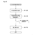
FIG. 10 is an explanatory diagram showing the flow of the modeling process in the method for manufacturing a modeled object according to the third embodiment. The flow of the modeling process in the third embodiment differs from the flow described with reference to FIG. are almost the same. The configuration of the modeling apparatus of the third embodiment is almost the same as the configuration of the
第2工程の吐出処理では、制御部101は、フラットスクリュー40の回転数を第1工程のときより増大させて、ノズル61からの造形材料MMの吐出量を増大させる。これによって、ノズル61の走査によって造形材料MMを堆積することができる面積を増大させることができる。そのため、第2工程でのノズル61の移動距離の総計を低減させることができ、第2造形部位MPbの単位時間あたりの造形時間を短縮することができる。なお、制御部101は、第2工程の吐出処理において、フラットスクリュー40の回転数を第1工程のときよりも増大させるとともに、ノズル61の移動速度を第1工程のときよりも増大させてもよい。
In the ejection process of the second step, the
第3実施形態の造形物の製造方法および造形装置によれば、フラットスクリュー40の回転数の簡易な制御によって、第2造形部位MPbの単位体積あたりの造形時間を短縮することができる。その他に、第3実施形態の製造方法および造形装置によれば、第3実施形態中で説明した種々の作用効果に加えて、上記の第1実施形態で説明したのと同様な種々の作用効果を奏することができる。
According to the manufacturing method and the modeling apparatus of the third embodiment, it is possible to shorten the modeling time per unit volume of the second modeling portion MPb by simply controlling the rotational speed of the
4.第4実施形態:
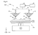
図11は、第4実施形態における造形装置100Aの構成を示す概略図である。第4実施形態の造形装置100Aの構成は、造形部110Aが2つの吐出部60を備えている点以外は、第1実施形態の造形装置100の構成とほぼ同じである。
4. Fourth embodiment:
FIG. 11 is a schematic diagram showing the configuration of a
造形部110Aは、2つの吐出部60はそれぞれ、第1ノズル61aと、第2ノズル61bと、を備える。第1ノズル61aと第2ノズル61bとはそれぞれ、流路65を介して、造形材料生成部30の連通孔56に並列に接続されている。第2ノズル61bの吐出口62bの孔径Dnは、第1ノズル61aの吐出口62aの孔径Dnよりも大きい。2つの吐出部60はそれぞれ、第1ノズル61aと第2ノズル61bに対応する開閉機構70を有している。制御部101は、以下に説明する造形工程において、2つのノズル61a,61bのうちの一方から造形材料MMを吐出させる吐出処理を実行する。
110 A of shaping|molding parts are provided with the
図12は、第4実施形態における造形物の製造方法による造形工程のフローを示す説明図である。第4実施形態の造形工程のフローは、第1工程と第2工程の内容が異なっている点以外は、第1実施形態で説明したフローと同じである。第4実施形態の造形工程では、第1工程と第2工程とにおいて、吐出処理において使用されるノズル61a,61bが交換され、第1造形部位MPaおよび第2造形部位MPbが造形される。
FIG. 12 is an explanatory diagram showing the flow of the modeling process by the method for manufacturing a modeled object according to the fourth embodiment. The flow of the modeling process of the fourth embodiment is the same as the flow described in the first embodiment, except that the contents of the first process and the second process are different. In the modeling process of the fourth embodiment, the
制御部101は、第1工程の吐出処理では、第1ノズル61aを使用して、第1造形部位MPaを造形する。また、制御部101は、第2工程の吐出処理では、第2ノズル61bを使用して、第2造形部位MPbを造形する。第2ノズル61bの吐出口62bの孔径Dnは、第1ノズル61aの吐出口62aの孔径Dnより大きいため、走査中のノズル61bの下に堆積される造形材料MMの幅はノズル61aよりも大きくなる。よって、第2ノズル61bを使用する吐出処理によって、第2造形部位MPbの単位体積あたりの造形時間を、第1造形部位MPaの単位体積あたりの造形時間より短縮することができる。
In the ejection process of the first step, the
第4実施形態の造形物の製造方法および造形装置100Aによれば、第2造形部位MPbを造形する際に、孔径Dnが大きい第2ノズル61bへ交換することによって、第2造形部位MPbの単位体積あたりの造形時間を簡易に短縮することができる。その他に、第4実施形態の製造方法および造形装置100Aによれば、上記の第1実施形態で説明したのと同様な種々の作用効果を奏することができる。
According to the manufacturing method of the modeled object and the
5.第5実施形態:
図13は、第5実施形態における造形装置100Bの構成を示す概略図である。第5実施形態の造形装置100Bの構成は、搬送部80を備えている点以外は、第1実施形態の造形装置100の構成とほぼ同じである。搬送部80は、例えば、ロボットアームによって構成される。搬送部80は、制御部101の制御下において、造形テーブル210の上に、以下に説明する造形工程の第2工程において用いられる予め準備された構造物STを搬送して配置する。
5. Fifth embodiment:
FIG. 13 is a schematic diagram showing the configuration of a
図14は、第5実施形態における造形物の製造方法による造形工程のフローを示す説明図である。第5実施形態の造形工程は、第2工程が工程a,bを含んでいる点以外は、第1実施形態で説明した造形工程とほぼ同じである。制御部101は、第1実施形態で説明したように、第1工程において、吐出処理によって、凹部RCを有する第1造形部位MPaを造形する。
FIG. 14 is an explanatory diagram showing the flow of the modeling process in the method for manufacturing a modeled object according to the fifth embodiment. The modeling process of the fifth embodiment is substantially the same as the modeling process described in the first embodiment, except that the second process includes steps a and b. As described in the first embodiment, in the first step, the
図15は、第2造形部位MPbを造形する第2工程を説明するための模式図である。第2工程の工程aでは、制御部101は、まず、搬送部80を制御して、第1造形部位MPaの凹部RC内に、構造物STを配置する。構造物STは、凹部RC内に全体が収まるように予め構成されている。構造物STは、造形装置100Bの吐出処理によって予め造形材料MMによって造形されたものであってもよいし、造形材料MMとは異なる材料で、造形装置100Bとは異なる装置によって製造されたものでもよい。構造物STの形状は特に限定されない。なお、搬送部80によって構造物STの配置に要する時間が構造物STに相当する体積の造形物を吐出処理によって造形するのに要する時間より短くなるように、構造物STの体積や、搬送部80による搬送速度、搬送距離が調整されていることが望ましい。
FIG. 15 is a schematic diagram for explaining the second step of modeling the second modeling portion MPb. In step a of the second step, the
第2工程の工程bでは、制御部101は、凹部RC内における構造物STが配置されていない空間に、吐出処理によって造形材料MMを堆積させて凹部RCを埋めることによって、第2造形部位MPbを造形する。構造物STは第2造形部位MPbの一部を構成する。
In the process b of the second process, the
第5実施形態の第2工程であれば、構造物STが予め凹部RC内に配置されていることによって、吐出処理によって造形材料MMを堆積させる空間が低減されているため、第2造形部位MPbの単位体積あたりの造形時間が短縮される。ここでの「第2造形部位MPbの単位体積あたりの造形時間」は、構造物STを一部に含む第2造形部位MPbによって埋められる凹部RC内の空間の体積を、構造物STを配置する工程aを含む第2工程に要した時間で除算した値を意味する。 In the second step of the fifth embodiment, since the structure ST is previously arranged in the recess RC, the space for depositing the modeling material MM is reduced by the ejection process. The molding time per unit volume of is shortened. Here, the "modeling time per unit volume of the second modeling site MPb" is the volume of the space in the recess RC filled by the second modeling site MPb partially including the structure ST. It means a value divided by the time required for the second step including step a.
第5実施形態の造形物の製造方法および造形装置100Bによれば、予め準備された構造物STの利用によって、第2造形部位MPbの単位体積あたりの造形時間を簡易に短縮することができる。その他に、第5実施形態の造形物の製造方法および造形装置100Bによれば、上記の第1実施形態で説明したのと同様な種々の作用効果を奏することができる。
According to the method for manufacturing a modeled object and the
6.他の実施形態:
上記の各実施形態で説明した種々の構成は、例えば、以下のように改変することが可能である。以下に説明する他の実施形態はいずれも、上記の各実施形態と同様に、発明を実施するための形態の一例として位置づけられる。
6. Other embodiments:
Various configurations described in the above embodiments can be modified, for example, as follows. All of the other embodiments described below are positioned as examples of modes for carrying out the invention, like each of the above-described embodiments.
6-1.他の実施形態1:
第2造形部位MPbの単位体積あたりの造形時間を短縮する方法は、上記の各実施形態で説明した方法に限定されることはない。例えば、上記の各実施形態で説明した方法を組み合わせて、第2造形部位MPbの単位体積あたりの造形時間を短縮してもよい。例えば、第1実施形態におけるノズル61の移動速度を低下させる制御と、第2実施形態におけるノズル61の移動方向を変更するときの造形材料MMの吐出量の低下量を低減させる制御と、第3実施形態におけるフラットスクリュー40の回転数を増大させる制御と、第4実施形態における第2ノズル61bに交換して使用する制御と、のうちの少なくとも2つを合わせて実行してもよい。また、第5実施形態の第2工程の工程bでの吐出制御において、第1実施形態、第2実施形態、第3実施形態、第4実施形態で説明した制御の少なくとも1つの制御を実行してもよい。
6-1. Alternative Embodiment 1:
The method for shortening the modeling time per unit volume of the second modeling portion MPb is not limited to the methods described in each of the above embodiments. For example, the methods described in the above embodiments may be combined to shorten the modeling time per unit volume of the second modeling portion MPb. For example, the control for reducing the moving speed of the
6-2.他の実施形態2:
造形装置100,100A,100Bの開閉機構70は、ピストンが流路65内に突出して流路65を閉塞するプランジャーを用いた機構や、流路65に交差する方向に移動して流路65を閉塞するシャッターを用いた機構によって構成されてもよい。開閉機構70は、上記実施形態のバタフライバルブや、上述のシャッター機構、プランジャー機構のうちの2つ以上を組み合わせて構成されてもよい。造形装置100,100A,100Bにおいて、開閉機構70は省略されてもよい。
6-2. Alternative Embodiment 2:
The opening/
6-3.他の実施形態3:
上記の第5実施形態において、第1ノズル61aと第2ノズル61bとは共通の造形材料生成部30から同じ種類の造形材料MMの供給を受けて吐出している。これに対して、上記の第5実施形態では、第1ノズル61aと第2ノズル61bとは別々の造形材料生成部30に接続されて、異なる種類の造形材料MMの供給を受けて吐出してもよい。
6-3. Alternative Embodiment 3:
In the above-described fifth embodiment, the
6-4.他の実施形態4:
上記の各実施形態において、材料供給部20は、複数のホッパーを備える構成を有していてもよい。この場合には、各ホッパーからフラットスクリュー40へと異なる材料が供給され、フラットスクリュー40の溝部42内において混合されて、造形材料が生成されてもよい。例えば、上記実施形態で説明した主材料となる粉末材料と、それに添加される溶媒やバインダーなどが別々のホッパーから並行してフラットスクリュー40に供給されてもよい。
6-4. Alternative Embodiment 4:
In each of the embodiments described above, the
6-5.他の実施形態5:
上記実施形態において、ソフトウェアによって実現された機能及び処理の一部又は全部は、ハードウェアによって実現されてもよい。また、ハードウェアによって実現された機能及び処理の一部又は全部は、ソフトウェアによって実現されてもよい。ハードウェアとしては、例えば、集積回路、ディスクリート回路、または、それらの回路を組み合わせた回路モジュールなど、各種回路を用いることができる。
6-5. Alternative Embodiment 5:
Some or all of the functions and processes implemented by software in the above embodiments may be implemented by hardware. Also, part or all of the functions and processes implemented by hardware may be implemented by software. As the hardware, various circuits such as integrated circuits, discrete circuits, or circuit modules combining these circuits can be used.
7.他の形態:
本発明は、上述の各実施形態や実施例に限られるものではなく、その趣旨を逸脱しない範囲において種々の形態(aspect)によって実現することができる。例えば、本発明は以下の形態として実現可能である。以下に記載する各形態中の技術的特徴に対応する上記の各実施形態中の技術的特徴は、本発明の課題の一部又は全部を解決するために、あるいは、本発明の効果の一部又は全部を達成するために、適宜、差し替えや、組み合わせを行うことが可能である。また、その技術的特徴が本明細書中において必須であると説明されていなければ、適宜、削除することが可能である。
7. Other forms:
The present invention is not limited to the above-described embodiments and examples, and can be implemented in various aspects without departing from the scope of the invention. For example, the present invention can be implemented as the following modes. The technical features in each of the above embodiments corresponding to the technical features in each of the embodiments described below are used to solve some or all of the problems of the present invention, or to achieve some of the effects of the present invention. Alternatively, replacements and combinations can be made as appropriate to achieve all. Also, if the technical feature is not described as essential in this specification, it can be deleted as appropriate.
(1)第1の形態は、三次元造形物の製造方法として提供される。この形態の製造方法は、回転しているフラットスクリューに材料を供給することによって、前記材料の少なくとも一部を溶融させた造形材料を生成し、造形テーブルとノズルとの相対位置を変えながら、前記造形テーブルに向かって、前記ノズルから前記造形材料を吐出する吐出処理によって、前記造形テーブルに前記造形材料を堆積させて、前記造形テーブルから前記ノズルに向かう方向に開口する凹部を有する第1造形部位を造形する第1工程と;前記吐出処理によって前記造形材料を前記凹部内に堆積させる工程を含み、前記凹部内に固定される第2造形部位を、前記第1造形部位の単位体積あたりの造形時間よりも短い単位体積あたりの造形時間で造形する第2工程と;を備える。
この形態の製造方法によれば、フラットスクリューを利用していることによって、小型な装置構成で、流動性を有する造形材料を簡易に生成しながら、造形材料の吐出を高い精度で制御することができる。よって、固体状態で準備された材料を用いる場合でも、より簡素な工程や構成によって、三次元造形物を、高い精度で、迅速に造形することができる。また、三次元造形物の内部構造を構成し、第1造形部位よりも高い造形精度が求められていない第2造形部位の造形時間を短縮できるため、迅速に三次元造形物を造形することができる。
(1) A first form is provided as a method for manufacturing a three-dimensional structure. In this mode of production, a material is supplied to a rotating flat screw to produce a modeling material in which at least a portion of the material is melted. A first modeling portion having a recess opening in a direction from the modeling table toward the nozzle by depositing the modeling material on the modeling table by a discharge process of discharging the modeling material from the nozzle toward the modeling table. and depositing the molding material in the recess by the dispensing process, wherein the second molding portion fixed in the recess is shaped per unit volume of the first molding portion. and a second step of modeling in a modeling time per unit volume shorter than the time.
According to the manufacturing method of this aspect, by using a flat screw, it is possible to easily generate a fluid modeling material with a small device configuration and to control the ejection of the modeling material with high accuracy. can. Therefore, even if a material prepared in a solid state is used, a three-dimensional modeled object can be quickly formed with high accuracy through simpler processes and configurations. In addition, it is possible to reduce the modeling time of the second modeling part, which constitutes the internal structure of the three-dimensional model and does not require higher modeling accuracy than the first modeling part, so that the three-dimensional model can be quickly modeled. can.
(2)上記形態の製造方法において、前記第2工程では、前記吐出処理における前記造形テーブルに対する前記ノズルの移動速度を前記第1工程のときよりも低下させることによって、前記ノズルの下に前記造形材料が堆積される範囲を前記第1工程のときより増大させてよい。
この形態の製造方法によれば、第2工程の吐出処理において、ノズルの移動速度を低下させた分だけ、ノズルの直下に堆積される造形材料の範囲が拡大される。そのため、第2工程において凹部内に造形材料を堆積させるためのノズルの移動距離を低減することができ、より密度の高い構造の第2造形部位を造形することができる。よって、三次元造形物の造形時間を短縮しつつ、その造形精度を高めることができる。
(2) In the manufacturing method of the above aspect, in the second step, the moving speed of the nozzle with respect to the modeling table in the ejection process is lower than that in the first step, so that the modeling is performed under the nozzle. The area over which material is deposited may be increased from that in the first step.
According to the manufacturing method of this aspect, in the ejection process of the second step, the range of the modeling material deposited directly under the nozzle is expanded by the amount corresponding to the reduction in the moving speed of the nozzle. Therefore, it is possible to reduce the moving distance of the nozzle for depositing the modeling material in the recess in the second step, and to form the second modeling portion with a higher density structure. Therefore, it is possible to improve the modeling accuracy while shortening the modeling time of the three-dimensional modeled object.
(3)上記形態の製造方法において、前記第1工程の前記吐出処理では、前記造形テーブルに対する前記ノズルの移動方向を変更するときに、前記ノズルからの前記造形材料の吐出量を低下させ;前記第2工程の前記吐出処理では、前記造形テーブルに対する前記ノズルの移動方向を変更するときに、前記ノズルからの前記造形材料の吐出量を前記第1工程のときよりも低下させてよい。
この形態の製造方法によれば、第2造形部位を造形する第2工程において、第1造形部位を造形する第1工程のときより、造形材料の吐出量の制御が簡略化されるため、第2造形部位の造形時間を短縮することができる。よって、三次元造形物を、より迅速に造形することができる。
(3) In the manufacturing method of the above aspect, in the ejection process of the first step, when changing the moving direction of the nozzle with respect to the modeling table, the amount of the modeling material ejected from the nozzle is reduced; In the ejection process of the second step, when changing the moving direction of the nozzle with respect to the modeling table, the amount of the modeling material ejected from the nozzle may be reduced from that in the first step.
According to the manufacturing method of this aspect, in the second step of modeling the second modeling portion, control of the discharge amount of the modeling material is simpler than in the first step of modeling the first modeling portion. 2. It is possible to shorten the molding time of the molding part. Therefore, a three-dimensional model can be modeled more quickly.
(4)上記形態の製造方法において、前記第2工程の前記吐出処理では、前記第1工程のときより、前記フラットスクリューの回転数を増大させてよい。
この形態の製造方法によれば、フラットスクリューの回転数の簡易な制御によって、第2造形部位の造形時間を、第1造形部位の造形時間より短縮することができる。
(4) In the manufacturing method of the above aspect, in the discharge process of the second step, the number of revolutions of the flat screw may be increased from that of the first step.
According to the manufacturing method of this aspect, the molding time of the second molding portion can be shortened more than the molding time of the first molding portion by simply controlling the rotational speed of the flat screw.
(5)上記形態の製造方法は、前記第1工程の前記吐出処理では、前記ノズルとして第1ノズルを使用し、前記第2工程の前記吐出処理では、前記ノズルとして、前記第1ノズルよりも吐出口の孔径が大きい第2ノズルを使用してよい。
この形態の製造方法によれば、孔径の異なるノズルの交換によって、第2造形部位の造形時間を、第1造形部位の造形時間より短縮することができる。
(5) In the manufacturing method of the above aspect, in the ejection process of the first step, the first nozzle is used as the nozzle, and in the ejection process of the second step, the nozzle has a higher density than the first nozzle. A second nozzle having a larger outlet hole diameter may be used.
According to the manufacturing method of this aspect, by exchanging nozzles with different hole diameters, the modeling time of the second modeling portion can be shortened more than the modeling time of the first modeling portion.
(6)上記形態の製造方法は、前記第2工程は、前記凹部内に前記第2造形部位の一部を構成する構造物を配置する工程と;前記凹部内における前記構造物が配置されていない空間に、前記吐出処理によって前記造形材料を堆積させる工程と;を含んでよい。
この形態の製造方法によれば、構造物によって、第2工程の吐出処理で造形される部位の体積を低減することができ、第2造形部位の単位体積あたりの造形時間を、第1造形部位の単位体積あたりの造形時間よりも簡易に短縮することができる。
(6) In the manufacturing method of the above aspect, the second step includes placing a structure forming part of the second modeling portion in the recess; and placing the structure in the recess. and depositing the build material by the dispensing process in an empty space.
According to the manufacturing method of this aspect, the structure can reduce the volume of the part to be formed in the discharge process of the second step, and the modeling time per unit volume of the second forming part can be reduced to the first forming part. The molding time per unit volume can be easily shortened.
(7)第2の形態は、三次元造形物を造形する造形装置として提供される。この形態の造形装置は、フラットスクリューを有し、回転している前記フラットスクリューに供給された材料の少なくとも一部を溶融させて造形材料を生成する材料生成部と;造形テーブルの上面に向かって前記造形材料を吐出するノズルと;前記造形テーブルと前記ノズルとの相対位置を変更する移動機構と;前記移動機構を制御して、前記造形テーブルと前記ノズルとの相対位置を変えながら、前記ノズルから前記造形テーブルの上面に前記造形材料を吐出させる吐出処理を実行する制御部と;を備える。前記制御部は、(i)前記吐出処理によって前記造形テーブルに前記造形材料を堆積させて、前記造形テーブルから前記ノズルに向かう方向に開口する凹部を有する第1造形部位を造形し、(ii)少なくとも、前記吐出処理によって前記造形材料を前記凹部内に堆積させる処理を実行し、前記凹部内に固定される第2造形部位を、前記第1造形部位の単位体積あたりの造形時間よりも短い単位体積あたりの造形時間で造形する。
この形態の造形装置によれば、フラットスクリューを利用していることによって、小型な装置構成で、流動性を有する造形材料を簡易に生成しつつ、造形材料の吐出を高い精度で制御することができる。よって、固体状態で準備された材料を用いる場合でも、より簡素な工程や構成によって、三次元造形物を、高い精度で、迅速に造形することができる。また、三次元造形物の内部構造を構成し、第1造形部位に較べて高い造形精度が求められていない第2造形部位の造形時間を短縮できるため、迅速に三次元造形物を造形することができる。
(7) A second form is provided as a modeling apparatus that models a three-dimensional modeled object. A modeling apparatus of this form has a flat screw, and a material producing section that melts at least a portion of a material supplied to the rotating flat screw to produce a modeling material; a nozzle for discharging the modeling material; a moving mechanism for changing the relative position between the modeling table and the nozzle; and the nozzle while controlling the moving mechanism to change the relative position between the modeling table and the nozzle. a control unit that executes a discharge process for discharging the modeling material from the upper surface of the modeling table; The control unit (i) deposits the modeling material on the modeling table by the ejection process to model a first modeling portion having a recess opening in a direction from the modeling table toward the nozzle, and (ii) At least, a process of depositing the modeling material in the recess by the discharge process is performed, and the second modeling portion fixed in the recess is formed by a unit shorter than the modeling time per unit volume of the first modeling portion. It is modeled in the modeling time per volume.
According to the modeling apparatus of this aspect, by using a flat screw, it is possible to easily generate a fluid modeling material with a small device configuration and to control the ejection of the modeling material with high accuracy. can. Therefore, even if a material prepared in a solid state is used, a three-dimensional modeled object can be quickly formed with high accuracy through simpler processes and configurations. In addition, it is possible to shorten the modeling time of the second modeling part, which constitutes the internal structure of the three-dimensional model and does not require high modeling accuracy compared to the first modeling part, so that the three-dimensional model can be quickly modeled. can be done.
本発明は、三次元造形物の製造方法や造形装置以外の種々の形態で実現することも可能である。例えば、前記の製造方法や造形装置によって造形された三次元造形物や、造形装置の制御方法、造形装置の制御装置、三次元造形物を構成する造形材料の堆積方法などの形態で実現することができる。また、前述の方法や制御方法を実現するためのコンピュータープログラム、そのコンピュータープログラムを記録した一時的でない記録媒体(non-transitory storage medium)等の形態で実現することができる。 The present invention can also be realized in various forms other than the method for manufacturing a three-dimensional model and the modeling apparatus. For example, it can be realized in the form of a three-dimensional modeled object modeled by the above-described manufacturing method or modeling apparatus, a control method for the modeling apparatus, a control apparatus for the modeling apparatus, a method for depositing modeling materials that constitute the three-dimensional modeled article, and the like. can be done. Moreover, it can be realized in the form of a computer program for realizing the above-described method and control method, a non-transitory storage medium in which the computer program is recorded, or the like.
20…材料供給部、22…連通路、30…造形材料生成部、31…スクリューケース、32…駆動モーター、40…フラットスクリュー、42…溝部、43…凸条部、44…材料流入口、46…中央部、48…溝形成面、50…スクリュー対面部、52…スクリュー対向面、54…案内溝、56…連通孔、58…ヒーター、60…吐出部、61…ノズル、61a…第1ノズル、61b…第2ノズル、62…吐出口、62a…吐出口、62b…吐出口、65…流路、70…開閉機構、72…駆動軸、73…弁体、74…バルブ駆動部、80…搬送部、100…三次元造形装置、100A…三次元造形装置、100B…三次元造形装置、101…制御部、110…造形部、110A…造形部、210…造形テーブル、211…上面、230…移動機構、Dn…孔径、G…ギャップ、M…モーター、MD…走査方向、ML…造形層、MLt…予定部位、MM…造形材料、MPa…第1造形部位、MPb…第2造形部位、PL…部分層、RC…凹部、RX…回転軸、ST…構造物
DESCRIPTION OF
Claims (6)
材料生成部によって材料の少なくとも一部を溶融させて造形材料を生成する可塑化工程と、
造形テーブルとノズルとの相対位置を変えながら、前記造形テーブルに向かって、前記ノズルから前記造形材料を吐出する吐出処理によって、前記造形テーブルから前記ノズルに向かう方向に開口する凹部を有する第1造形部位を造形する第1工程と、
前記吐出処理によって前記造形材料を前記凹部内に堆積させ、前記凹部内に固定される第2造形部位を、前記第1造形部位の単位体積あたりの造形時間よりも短い単位体積あたりの造形時間で造形する第2工程と、
を備え、
前記材料生成部は、溝が形成された溝形成面を有し、回転可能なフラットスクリューと、前記溝形成面に対向し、前記ノズルに連通する連通孔が形成されたスクリュー対面部と、を備え、
前記フラットスクリューは、回転軸に沿った方向の長さが、前記回転軸に垂直な方向の長さよりも短く、
前記第2工程では、前記吐出処理における前記造形テーブルに対する前記ノズルの移動速度を前記第1工程のときよりも低下させることによって、前記ノズルの下に前記造形材料が堆積される範囲を前記第1工程のときより増大させる、製造方法。 A method for manufacturing a three-dimensional model,
a plasticizing step of melting at least a portion of the material by the material generating unit to generate a modeling material;
A first modeling having a recess opening in a direction from the modeling table toward the nozzle by an ejection process of ejecting the modeling material from the nozzle toward the modeling table while changing the relative position between the modeling table and the nozzle. A first step of shaping a part;
The molding material is deposited in the recess by the discharge process, and the second molding portion fixed in the recess is formed in a molding time per unit volume that is shorter than the molding time per unit volume of the first molding portion. a second step of molding;
with
The material generating unit has a grooved surface on which grooves are formed, and includes a rotatable flat screw and a screw facing portion facing the grooved surface and formed with a communication hole communicating with the nozzle. prepared,
The flat screw has a length in a direction along the rotation axis shorter than a length in a direction perpendicular to the rotation axis,
In the second step, the moving speed of the nozzle with respect to the modeling table in the ejection process is made lower than that in the first step, so that the range in which the modeling material is deposited under the nozzle is reduced to the first range. A manufacturing method that increases during the process.
材料生成部によって材料の少なくとも一部を溶融させて造形材料を生成する可塑化工程と、
造形テーブルとノズルとの相対位置を変えながら、前記造形テーブルに向かって、前記ノズルから前記造形材料を吐出する吐出処理によって、前記造形テーブルから前記ノズルに向かう方向に開口する凹部を有する第1造形部位を造形する第1工程と、
前記吐出処理によって前記造形材料を前記凹部内に堆積させ、前記凹部内に固定される第2造形部位を、前記第1造形部位の単位体積あたりの造形時間よりも短い単位体積あたりの造形時間で造形する第2工程と、
を備え、
前記材料生成部は、溝が形成された溝形成面を有し、回転可能なフラットスクリューと、前記溝形成面に対向し、前記ノズルに連通する連通孔が形成されたスクリュー対面部と、を備え、
前記フラットスクリューは、回転軸に沿った方向の長さが、前記回転軸に垂直な方向の長さよりも短く、
前記第1工程の前記吐出処理では、前記造形テーブルに対する前記ノズルの移動方向を変更するときに、前記ノズルからの前記造形材料の吐出量を低下させ、
前記第2工程の前記吐出処理では、前記造形テーブルに対する前記ノズルの移動方向を変更するときに、前記ノズルからの前記造形材料の吐出量を前記第1工程のときよりも低下させない、製造方法。 A method for manufacturing a three-dimensional model,
a plasticizing step of melting at least a portion of the material by the material generating unit to generate a modeling material;
A first modeling having a recess opening in a direction from the modeling table toward the nozzle by an ejection process of ejecting the modeling material from the nozzle toward the modeling table while changing the relative position between the modeling table and the nozzle. A first step of shaping a part;
The molding material is deposited in the recess by the discharge process, and the second molding portion fixed in the recess is formed in a molding time per unit volume that is shorter than the molding time per unit volume of the first molding portion. a second step of molding;
with
The material generating unit has a grooved surface on which grooves are formed, and includes a rotatable flat screw and a screw facing portion facing the grooved surface and formed with a communication hole communicating with the nozzle. prepared,
The flat screw has a length in a direction along the rotation axis shorter than a length in a direction perpendicular to the rotation axis,
In the ejection process of the first step, when changing the moving direction of the nozzle with respect to the modeling table, reducing the ejection amount of the modeling material from the nozzle,
The manufacturing method, wherein in the ejection process of the second step, when changing the moving direction of the nozzle with respect to the modeling table, the amount of the modeling material ejected from the nozzle is not reduced more than that in the first step.
前記第2工程の前記吐出処理では、前記第1工程のときより、前記フラットスクリューの回転数を増大させる、製造方法。 The manufacturing method according to claim 1 or claim 2 ,
The manufacturing method, wherein in the discharge process of the second step, the number of rotations of the flat screw is increased more than in the first step.
前記第2工程は、
前記凹部内に前記第2造形部位の一部を構成する構造物を配置する工程と、
前記凹部内における前記構造物が配置されていない空間に、前記吐出処理によって前記造形材料を堆積させる工程と、
を含む、製造方法。 The manufacturing method according to any one of claims 1 to 3 ,
The second step is
arranging a structure forming part of the second modeling portion in the recess;
a step of depositing the modeling material by the ejection process in a space in the recess where the structure is not arranged;
A manufacturing method, including:
材料の少なくとも一部を溶融させて造形材料を生成する材料生成部と、
造形テーブルの上面に向かって前記造形材料を吐出するノズルと、
前記造形テーブルと前記ノズルとの相対位置を変更する移動機構と、
前記移動機構を制御して、前記造形テーブルと前記ノズルとの相対位置を変えながら、前記ノズルから前記造形テーブルの上面に前記造形材料を吐出させる吐出処理を実行する制御部と、
を備え、
前記材料生成部は、溝が形成された溝形成面を有し、回転可能なフラットスクリューと、前記溝形成面に対向し、前記ノズルに連通する連通孔が形成されたスクリュー対面部と、を備え、
前記フラットスクリューは、回転軸に沿った方向の長さが、前記回転軸に垂直な方向の長さよりも短く、
前記制御部は、前記移動機構を制御することで、前記造形テーブルと前記ノズルとの相対移動速度を制御し、
前記制御部は、
前記吐出処理によって前記造形テーブルに前記造形材料を堆積させて、前記造形テーブルから前記ノズルに向かう方向に開口する凹部を有する第1造形部位を造形する第1処理と、
前記吐出処理によって前記造形材料を前記凹部内に堆積させ、前記凹部内に固定される第2造形部位を、前記第1造形部位の単位体積あたりの造形時間よりも短い単位体積あたりの造形時間で造形する第2処理と、を実行し、
前記第2処理では、前記吐出処理における前記相対移動速度を前記第1処理のときよりも低下させることによって、前記ノズルの下に前記造形材料が堆積される範囲を前記第1処理のときより増大させる、
造形装置。 A molding apparatus for molding a three-dimensional object,
a material generation unit that melts at least a portion of the material to generate the modeling material;
a nozzle for discharging the modeling material toward the upper surface of the modeling table;
a moving mechanism for changing the relative position between the modeling table and the nozzle;
a control unit that controls the moving mechanism to execute a discharge process of discharging the modeling material from the nozzle onto the upper surface of the modeling table while changing the relative position between the modeling table and the nozzle;
with
The material generating unit has a grooved surface on which grooves are formed, and includes a rotatable flat screw and a screw facing portion facing the grooved surface and formed with a communication hole communicating with the nozzle. prepared,
The flat screw has a length in a direction along the rotation axis shorter than a length in a direction perpendicular to the rotation axis,
The control unit controls the relative movement speed between the modeling table and the nozzle by controlling the moving mechanism,
The control unit
a first process of depositing the modeling material on the modeling table by the discharging process to model a first modeling portion having a recess opening in a direction from the modeling table toward the nozzle;
The molding material is deposited in the recess by the discharge process, and the second molding portion fixed in the recess is formed in a molding time per unit volume that is shorter than the molding time per unit volume of the first molding portion. a second process of modeling, and
In the second process, the relative movement speed in the discharge process is made lower than in the first process, thereby increasing the range in which the modeling material is deposited under the nozzle as compared to the first process. let
molding device.
材料の少なくとも一部を溶融させて造形材料を生成する材料生成部と、
造形テーブルの上面に向かって前記造形材料を吐出するノズルと、
前記造形テーブルと前記ノズルとの相対位置を変更する移動機構と、
前記移動機構を制御して、前記造形テーブルと前記ノズルとの相対位置を変えながら、前記ノズルから前記造形テーブルの上面に前記造形材料を吐出させる吐出処理を実行する制御部と、
を備え、
前記材料生成部は、溝が形成された溝形成面を有し、回転可能なフラットスクリューと、前記溝形成面に対向し、前記ノズルに連通する連通孔が形成されたスクリュー対面部と、を備え、
前記フラットスクリューは、回転軸に沿った方向の長さが、前記回転軸に垂直な方向の長さよりも短く、
前記制御部は、前記フラットスクリューの回転数を制御することによって前記ノズルからの前記造形材料の吐出量を制御し、
前記制御部は、
前記吐出処理によって前記造形テーブルに前記造形材料を堆積させて、前記造形テーブルから前記ノズルに向かう方向に開口する凹部を有する第1造形部位を造形する第1処理と、
前記吐出処理によって前記造形材料を前記凹部内に堆積させ、前記凹部内に固定される第2造形部位を、前記第1造形部位の単位体積あたりの造形時間よりも短い単位体積あたりの造形時間で造形する第2処理と、を実行し、
前記第1処理の前記吐出処理では、前記造形テーブルに対する前記ノズルの相対的な移動方向を変更するときに、前記ノズルからの前記造形材料の吐出量を低下させ、
前記第2処理の前記吐出処理では、前記造形テーブルに対する前記ノズルの相対的な移動方向を変更するときに、前記ノズルからの前記造形材料の吐出量を前記第1処理のときよりも低下させない、
造形装置。 A molding apparatus for molding a three-dimensional object,
a material generation unit that melts at least a portion of the material to generate the modeling material;
a nozzle for discharging the modeling material toward the upper surface of the modeling table;
a moving mechanism for changing the relative position between the modeling table and the nozzle;
a control unit that controls the moving mechanism to execute a discharge process of discharging the modeling material from the nozzle onto the upper surface of the modeling table while changing the relative position between the modeling table and the nozzle;
with
The material generating unit has a grooved surface on which grooves are formed, and includes a rotatable flat screw and a screw facing portion facing the grooved surface and formed with a communication hole communicating with the nozzle. prepared,
The flat screw has a length in a direction along the rotation axis shorter than a length in a direction perpendicular to the rotation axis,
The control unit controls the discharge amount of the modeling material from the nozzle by controlling the rotation speed of the flat screw,
The control unit
a first process of depositing the modeling material on the modeling table by the discharging process to model a first modeling portion having a recess opening in a direction from the modeling table toward the nozzle;
The molding material is deposited in the recess by the discharge process, and the second molding portion fixed in the recess is formed in a molding time per unit volume that is shorter than the molding time per unit volume of the first molding portion. a second process of modeling, and
In the ejection process of the first process, when changing the relative movement direction of the nozzle with respect to the modeling table, reducing the ejection amount of the modeling material from the nozzle,
In the ejection process of the second process, when changing the relative movement direction of the nozzle with respect to the modeling table, the amount of the modeling material ejected from the nozzle is not reduced more than in the first process.
molding device.
Priority Applications (3)
| Application Number | Priority Date | Filing Date | Title |
|---|---|---|---|
| JP2018045414A JP7163595B2 (en) | 2018-03-13 | 2018-03-13 | 3D object manufacturing method and 3D object modeling apparatus |
| US16/299,574 US20190283321A1 (en) | 2018-03-13 | 2019-03-12 | Manufacturing Method Of Three-Dimensional Formed Object And Forming Apparatus Of Three-Dimensional Formed Object |
| CN201910183147.1A CN110271179B (en) | 2018-03-13 | 2019-03-12 | Manufacturing method of three-dimensional molded object and molding device of three-dimensional molded object |
Applications Claiming Priority (1)
| Application Number | Priority Date | Filing Date | Title |
|---|---|---|---|
| JP2018045414A JP7163595B2 (en) | 2018-03-13 | 2018-03-13 | 3D object manufacturing method and 3D object modeling apparatus |
Publications (2)
| Publication Number | Publication Date |
|---|---|
| JP2019155724A JP2019155724A (en) | 2019-09-19 |
| JP7163595B2 true JP7163595B2 (en) | 2022-11-01 |
Family
ID=67905101
Family Applications (1)
| Application Number | Title | Priority Date | Filing Date |
|---|---|---|---|
| JP2018045414A Active JP7163595B2 (en) | 2018-03-13 | 2018-03-13 | 3D object manufacturing method and 3D object modeling apparatus |
Country Status (3)
| Country | Link |
|---|---|
| US (1) | US20190283321A1 (en) |
| JP (1) | JP7163595B2 (en) |
| CN (1) | CN110271179B (en) |
Families Citing this family (14)
| Publication number | Priority date | Publication date | Assignee | Title |
|---|---|---|---|---|
| JP7024599B2 (en) | 2018-05-23 | 2022-02-24 | セイコーエプソン株式会社 | Thermoplastic equipment, injection molding machine and modeling equipment |
| JP7131248B2 (en) * | 2018-09-25 | 2022-09-06 | セイコーエプソン株式会社 | Plasticizing device and three-dimensional modeling device |
| JP7163692B2 (en) * | 2018-09-25 | 2022-11-01 | セイコーエプソン株式会社 | Plasticizing device and three-dimensional modeling device |
| JP7180244B2 (en) | 2018-09-27 | 2022-11-30 | セイコーエプソン株式会社 | Plasticizing device |
| JP7272047B2 (en) | 2019-03-27 | 2023-05-12 | セイコーエプソン株式会社 | Plasticizing device and three-dimensional modeling device |
| JP7400327B2 (en) * | 2019-10-16 | 2023-12-19 | セイコーエプソン株式会社 | Three-dimensional object manufacturing method and data processing device |
| JP7512599B2 (en) * | 2020-01-30 | 2024-07-09 | セイコーエプソン株式会社 | Method for manufacturing three-dimensional object and information processing device |
| JP7459546B2 (en) * | 2020-02-12 | 2024-04-02 | セイコーエプソン株式会社 | A method for manufacturing a three-dimensional object, and a three-dimensional printing device |
| JP7428621B2 (en) * | 2020-09-25 | 2024-02-06 | 株式会社神戸製鋼所 | How to set printing conditions, additive manufacturing method, additive manufacturing system, and program |
| FR3114767B1 (en) * | 2020-10-02 | 2023-03-31 | Univ Bretagne Sud | Use of a composition comprising a high content of inorganic material(s) and a thermoplastic elastomer in an additive manufacturing process |
| JP7567350B2 (en) * | 2020-10-20 | 2024-10-16 | セイコーエプソン株式会社 | Three-dimensional modeling device and method for manufacturing three-dimensional object |
| JP7547936B2 (en) * | 2020-10-30 | 2024-09-10 | セイコーエプソン株式会社 | 3D modeling equipment |
| JP7639513B2 (en) * | 2021-04-14 | 2025-03-05 | セイコーエプソン株式会社 | Method and apparatus for manufacturing three-dimensional objects |
| JP7619143B2 (en) * | 2021-04-22 | 2025-01-22 | セイコーエプソン株式会社 | Method for manufacturing three-dimensional object and information processing device |
Citations (9)
| Publication number | Priority date | Publication date | Assignee | Title |
|---|---|---|---|---|
| US20140048970A1 (en) | 2012-08-16 | 2014-02-20 | Stratasys, Inc. | Draw control for extrusion-based additive manufacturing systems |
| US20140048969A1 (en) | 2012-08-16 | 2014-02-20 | Stratasys, Inc. | Print head nozzle for use with additive manufacturing system |
| JP2016531770A (en) | 2013-06-24 | 2016-10-13 | プレジデント アンド フェローズ オブ ハーバード カレッジ | Printed three-dimensional (3D) functional component and manufacturing method |
| WO2017038985A1 (en) | 2015-09-04 | 2017-03-09 | Jsr株式会社 | Method for manufacturing three-dimensional modeled object and nozzle movement path data creation method used in same, and device for manufacturing three-dimensional modeled object and nozzle movement path data creation program used in same |
| JP2017105177A (en) | 2015-12-08 | 2017-06-15 | ゼロックス コーポレイションXerox Corporation | System and method for operation of multi-nozzle extrusion printhead in three-dimensional object printer |
| JP2017523934A (en) | 2014-08-05 | 2017-08-24 | スターフォート デス ストゥベンルッス モリッツ | Granule / liquid flow control device for 3D printer head supplied with granules and / or liquid |
| WO2017152133A1 (en) | 2016-03-03 | 2017-09-08 | Desktop Metal, Inc. | Magnetohydrodynamic deposition of metal in manufacturing |
| JP2017165041A (en) | 2016-03-17 | 2017-09-21 | 株式会社リコー | Information processing apparatus, molding system, program, and information processing method |
| JP2021505432A (en) | 2017-12-06 | 2021-02-18 | マッシビット スリーディー プリンティング テクノロジーズ リミテッド | Manufacture of 3D objects with complex shapes |
Family Cites Families (9)
| Publication number | Priority date | Publication date | Assignee | Title |
|---|---|---|---|---|
| JPH04366617A (en) * | 1991-06-13 | 1992-12-18 | Mitsui Eng & Shipbuild Co Ltd | Optical shaping method |
| EP2837444A1 (en) * | 2013-08-14 | 2015-02-18 | BAE Systems PLC | Object production |
| TWI491496B (en) * | 2014-05-08 | 2015-07-11 | 三緯國際立體列印科技股份有限公司 | Three dimensional printing apparatus, printing calibration board and three dimensional printing calibration method thereof |
| CN104044271B (en) * | 2014-06-17 | 2017-01-11 | 苏州汉印精密机械科技有限公司 | Dual-printing head mechanism for 3D printer, 3D printer and printing method |
| JP6669985B2 (en) * | 2015-11-12 | 2020-03-18 | セイコーエプソン株式会社 | Manufacturing method of three-dimensional objects |
| JP6843968B2 (en) * | 2016-08-22 | 2021-03-17 | ストラタシス,インコーポレイテッド | How to print 3D parts using a multi-axis robot build system and how to print parts outside the oven 3D |
| CN206124217U (en) * | 2016-09-14 | 2017-04-26 | 深圳新域中科科技股份有限公司 | 3D printer melt extruding means of speed adjusting temperature soon |
| CN107584115B (en) * | 2017-08-10 | 2019-02-19 | 大连海博瑞思科技有限公司 | Five-axis linkage printing method for impeller blades with spatially twisted surfaces |
| CN107403469B (en) * | 2017-08-10 | 2020-09-22 | 河海大学常州校区 | An Adaptive Scanning Speed Method for Improving the Quality of Chamfering |
-
2018
- 2018-03-13 JP JP2018045414A patent/JP7163595B2/en active Active
-
2019
- 2019-03-12 CN CN201910183147.1A patent/CN110271179B/en active Active
- 2019-03-12 US US16/299,574 patent/US20190283321A1/en not_active Abandoned
Patent Citations (9)
| Publication number | Priority date | Publication date | Assignee | Title |
|---|---|---|---|---|
| US20140048970A1 (en) | 2012-08-16 | 2014-02-20 | Stratasys, Inc. | Draw control for extrusion-based additive manufacturing systems |
| US20140048969A1 (en) | 2012-08-16 | 2014-02-20 | Stratasys, Inc. | Print head nozzle for use with additive manufacturing system |
| JP2016531770A (en) | 2013-06-24 | 2016-10-13 | プレジデント アンド フェローズ オブ ハーバード カレッジ | Printed three-dimensional (3D) functional component and manufacturing method |
| JP2017523934A (en) | 2014-08-05 | 2017-08-24 | スターフォート デス ストゥベンルッス モリッツ | Granule / liquid flow control device for 3D printer head supplied with granules and / or liquid |
| WO2017038985A1 (en) | 2015-09-04 | 2017-03-09 | Jsr株式会社 | Method for manufacturing three-dimensional modeled object and nozzle movement path data creation method used in same, and device for manufacturing three-dimensional modeled object and nozzle movement path data creation program used in same |
| JP2017105177A (en) | 2015-12-08 | 2017-06-15 | ゼロックス コーポレイションXerox Corporation | System and method for operation of multi-nozzle extrusion printhead in three-dimensional object printer |
| WO2017152133A1 (en) | 2016-03-03 | 2017-09-08 | Desktop Metal, Inc. | Magnetohydrodynamic deposition of metal in manufacturing |
| JP2017165041A (en) | 2016-03-17 | 2017-09-21 | 株式会社リコー | Information processing apparatus, molding system, program, and information processing method |
| JP2021505432A (en) | 2017-12-06 | 2021-02-18 | マッシビット スリーディー プリンティング テクノロジーズ リミテッド | Manufacture of 3D objects with complex shapes |
Also Published As
| Publication number | Publication date |
|---|---|
| US20190283321A1 (en) | 2019-09-19 |
| CN110271179B (en) | 2022-02-11 |
| JP2019155724A (en) | 2019-09-19 |
| CN110271179A (en) | 2019-09-24 |
Similar Documents
| Publication | Publication Date | Title |
|---|---|---|
| JP7163595B2 (en) | 3D object manufacturing method and 3D object modeling apparatus | |
| JP7180078B2 (en) | Three-dimensional object manufacturing method and modeling apparatus | |
| JP7147324B2 (en) | material plasticizer | |
| JP7347610B2 (en) | 3D printing device and method for manufacturing 3D objects | |
| EP3628469B1 (en) | Plasticizing device and three-dimensional shaping device | |
| US11370167B2 (en) | Shaping stage, three-dimensional shaping apparatus, and control method of three-dimensional shaping apparatus | |
| JP7172075B2 (en) | Three-dimensional modeling system, data generation device, method for generating data, and program | |
| JP7043876B2 (en) | Manufacturing method and modeling equipment for 3D objects | |
| JP7172368B2 (en) | Three-dimensional modeling apparatus and method for manufacturing three-dimensional model | |
| JP7139864B2 (en) | Three-dimensional modeling system and data generation device | |
| CN110524821A (en) | Plasticizing apparatus, injection (mo(u)lding) machine and styling apparatus | |
| JP7172566B2 (en) | Three-dimensional modeling apparatus and method for manufacturing three-dimensional model | |
| JP7180244B2 (en) | Plasticizing device | |
| JP7131248B2 (en) | Plasticizing device and three-dimensional modeling device | |
| JP7183677B2 (en) | Plasticizing device and three-dimensional modeling device | |
| JP2020032564A (en) | Method for manufacturing three-dimensional object and three-dimensional object | |
| JP2020032623A (en) | Three-dimensional printing apparatus and method for manufacturing three-dimensional printing object | |
| JP7400327B2 (en) | Three-dimensional object manufacturing method and data processing device | |
| JP7342477B2 (en) | Three-dimensional object manufacturing method and three-dimensional printing device | |
| JP2020006519A (en) | Method for manufacturing three-dimensional object and three-dimensional object | |
| JP7619143B2 (en) | Method for manufacturing three-dimensional object and information processing device | |
| JP7354691B2 (en) | Plasticizing equipment, three-dimensional modeling equipment and injection molding equipment | |
| JP2023033888A (en) | Three-dimensional molding device | |
| JP7547900B2 (en) | Method for manufacturing three-dimensional object, information processing device, and three-dimensional modeling device | |
| JP2021066046A (en) | Manufacturing method of three-dimensional molded product and data processing device |
Legal Events
| Date | Code | Title | Description |
|---|---|---|---|
| A621 | Written request for application examination |
Free format text: JAPANESE INTERMEDIATE CODE: A621 Effective date: 20210105 |
|
| A977 | Report on retrieval |
Free format text: JAPANESE INTERMEDIATE CODE: A971007 Effective date: 20211207 |
|
| A131 | Notification of reasons for refusal |
Free format text: JAPANESE INTERMEDIATE CODE: A131 Effective date: 20211221 |
|
| A521 | Request for written amendment filed |
Free format text: JAPANESE INTERMEDIATE CODE: A523 Effective date: 20220216 |
|
| A131 | Notification of reasons for refusal |
Free format text: JAPANESE INTERMEDIATE CODE: A131 Effective date: 20220719 |
|
| A521 | Request for written amendment filed |
Free format text: JAPANESE INTERMEDIATE CODE: A523 Effective date: 20220909 |
|
| TRDD | Decision of grant or rejection written | ||
| A01 | Written decision to grant a patent or to grant a registration (utility model) |
Free format text: JAPANESE INTERMEDIATE CODE: A01 Effective date: 20220920 |
|
| A61 | First payment of annual fees (during grant procedure) |
Free format text: JAPANESE INTERMEDIATE CODE: A61 Effective date: 20221003 |
|
| R150 | Certificate of patent or registration of utility model |
Ref document number: 7163595 Country of ref document: JP Free format text: JAPANESE INTERMEDIATE CODE: R150 |