JP7151873B2 - inspection equipment - Google Patents
inspection equipment Download PDFInfo
- Publication number
- JP7151873B2 JP7151873B2 JP2021508497A JP2021508497A JP7151873B2 JP 7151873 B2 JP7151873 B2 JP 7151873B2 JP 2021508497 A JP2021508497 A JP 2021508497A JP 2021508497 A JP2021508497 A JP 2021508497A JP 7151873 B2 JP7151873 B2 JP 7151873B2
- Authority
- JP
- Japan
- Prior art keywords
- imaging
- image
- angle
- partial area
- photographing
- Prior art date
- Legal status (The legal status is an assumption and is not a legal conclusion. Google has not performed a legal analysis and makes no representation as to the accuracy of the status listed.)
- Active
Links
Images




Classifications
-
- G—PHYSICS
- G01—MEASURING; TESTING
- G01N—INVESTIGATING OR ANALYSING MATERIALS BY DETERMINING THEIR CHEMICAL OR PHYSICAL PROPERTIES
- G01N21/00—Investigating or analysing materials by the use of optical means, i.e. using sub-millimetre waves, infrared, visible or ultraviolet light
- G01N21/84—Systems specially adapted for particular applications
- G01N21/88—Investigating the presence of flaws or contamination
- G01N21/8806—Specially adapted optical and illumination features
-
- G—PHYSICS
- G01—MEASURING; TESTING
- G01N—INVESTIGATING OR ANALYSING MATERIALS BY DETERMINING THEIR CHEMICAL OR PHYSICAL PROPERTIES
- G01N21/00—Investigating or analysing materials by the use of optical means, i.e. using sub-millimetre waves, infrared, visible or ultraviolet light
- G01N21/84—Systems specially adapted for particular applications
- G01N21/88—Investigating the presence of flaws or contamination
- G01N21/8851—Scan or image signal processing specially adapted therefor, e.g. for scan signal adjustment, for detecting different kinds of defects, for compensating for structures, markings, edges
-
- H—ELECTRICITY
- H04—ELECTRIC COMMUNICATION TECHNIQUE
- H04N—PICTORIAL COMMUNICATION, e.g. TELEVISION
- H04N23/00—Cameras or camera modules comprising electronic image sensors; Control thereof
- H04N23/60—Control of cameras or camera modules
- H04N23/64—Computer-aided capture of images, e.g. transfer from script file into camera, check of taken image quality, advice or proposal for image composition or decision on when to take image
-
- H—ELECTRICITY
- H04—ELECTRIC COMMUNICATION TECHNIQUE
- H04N—PICTORIAL COMMUNICATION, e.g. TELEVISION
- H04N23/00—Cameras or camera modules comprising electronic image sensors; Control thereof
- H04N23/60—Control of cameras or camera modules
- H04N23/667—Camera operation mode switching, e.g. between still and video, sport and normal or high- and low-resolution modes
-
- H—ELECTRICITY
- H04—ELECTRIC COMMUNICATION TECHNIQUE
- H04N—PICTORIAL COMMUNICATION, e.g. TELEVISION
- H04N23/00—Cameras or camera modules comprising electronic image sensors; Control thereof
- H04N23/90—Arrangement of cameras or camera modules, e.g. multiple cameras in TV studios or sports stadiums
-
- G—PHYSICS
- G01—MEASURING; TESTING
- G01N—INVESTIGATING OR ANALYSING MATERIALS BY DETERMINING THEIR CHEMICAL OR PHYSICAL PROPERTIES
- G01N21/00—Investigating or analysing materials by the use of optical means, i.e. using sub-millimetre waves, infrared, visible or ultraviolet light
- G01N21/84—Systems specially adapted for particular applications
- G01N21/88—Investigating the presence of flaws or contamination
- G01N21/8806—Specially adapted optical and illumination features
- G01N2021/8809—Adjustment for highlighting flaws
-
- G—PHYSICS
- G01—MEASURING; TESTING
- G01N—INVESTIGATING OR ANALYSING MATERIALS BY DETERMINING THEIR CHEMICAL OR PHYSICAL PROPERTIES
- G01N21/00—Investigating or analysing materials by the use of optical means, i.e. using sub-millimetre waves, infrared, visible or ultraviolet light
- G01N21/84—Systems specially adapted for particular applications
- G01N21/88—Investigating the presence of flaws or contamination
- G01N21/8851—Scan or image signal processing specially adapted therefor, e.g. for scan signal adjustment, for detecting different kinds of defects, for compensating for structures, markings, edges
- G01N2021/8854—Grading and classifying of flaws
Landscapes
- Signal Processing (AREA)
- Engineering & Computer Science (AREA)
- Biochemistry (AREA)
- General Health & Medical Sciences (AREA)
- Health & Medical Sciences (AREA)
- Life Sciences & Earth Sciences (AREA)
- Chemical & Material Sciences (AREA)
- Analytical Chemistry (AREA)
- Pathology (AREA)
- Physics & Mathematics (AREA)
- General Physics & Mathematics (AREA)
- Immunology (AREA)
- Multimedia (AREA)
- Computer Vision & Pattern Recognition (AREA)
- Investigating Materials By The Use Of Optical Means Adapted For Particular Applications (AREA)
- Image Analysis (AREA)
Description
本発明は、検査装置、検査方法、および記録媒体に関する。 The present invention relates to an inspection apparatus, an inspection method, and a recording medium.
通常、工場などで製造された製品については、製品の表面に疵などの異常がないかどうかの検査が実施される。このような検査を自動化したシステムとして、対象物を撮影した画像を解析した結果に基づいて対象物の異常を検出する技術が各種提案ないし実用化されている。 Generally, products manufactured in a factory or the like are inspected for defects such as flaws on the surface of the product. As systems for automating such inspections, various techniques have been proposed or put into practical use to detect abnormalities in an object based on the results of analysis of an image of the object.
例えば、特許文献1には、対象物の表面を異なる撮影方向から撮影した複数の画像を取得し、これら複数の画像を分析することにより、様々な疵を検出するようにした技術が記載されている。また、特許文献1には、対象物の表面を異なる方向から照明し、その照明の方向を前後左右に変更させることで複数の方向からの画像を取得して検査精度を向上させた装置についても記載されている。 For example, Patent Document 1 describes a technique for detecting various flaws by acquiring a plurality of images of the surface of an object photographed from different photographing directions and analyzing the plurality of images. there is Patent document 1 also describes an apparatus that illuminates the surface of an object from different directions and changes the direction of the illumination from front to back, left to right, and acquires images from a plurality of directions to improve inspection accuracy. Have been described.
対象物を照明する方向や撮影する方向などの違う様々な撮影条件の下で対象物を撮影することによって、検査の精度を高めることはできる。しかしながら、撮影条件の種類が増えれば、1対象物当たりの平均検査時間が長くなる。この平均検査時間を短縮するために撮影条件の数を減らせば、検査精度が低下する。また、様々な撮影条件の中から適する撮影条件を事前調整によって決定するならば、検査の高精度化と平均検査時間の短縮はできるけれども事前調整コストがかかる。そのため、検査の高精度化、平均検査時間の短縮、事前調整コストの削減をすべて満足させるのは困難であった。 The accuracy of inspection can be improved by photographing the object under various photographing conditions such as the direction in which the object is illuminated and the direction in which the object is photographed. However, as the types of imaging conditions increase, the average inspection time per object increases. If the number of imaging conditions is reduced in order to shorten the average inspection time, the inspection accuracy will be lowered. Further, if suitable imaging conditions are determined by preadjustment from various imaging conditions, the accuracy of inspection can be improved and the average inspection time can be shortened, but preadjustment costs are incurred. Therefore, it has been difficult to satisfy all of the requirements of higher inspection accuracy, shorter average inspection time, and lower pre-adjustment costs.
本発明の目的は、上述した課題を解決する検査装置を提供することにある。 An object of the present invention is to provide an inspection apparatus that solves the above problems.
本発明の一形態に係る検査装置は、
対象物を撮影する条件を様々な撮影条件に変更する変更手段と、
所定の条件が成立するまでに実施する対象物の検査では、前記様々な撮影条件の全てを選択し、前記所定の条件が成立した後に実施する対象物の検査では、前記撮影条件毎の有効度に基づいて前記様々な撮影条件から1または複数の撮影条件を選択する撮影条件選択手段と、
前記変更手段を制御することによって、前記選択された撮影条件のそれぞれの下で前記対象物の画像を取得する画像取得手段と、
前記取得された画像に基づいて前記対象物の異常を検出する異常検出手段と、
前記取得された画像に基づいて前記有効度を更新する有効度更新手段と、
を備える。An inspection apparatus according to one aspect of the present invention includes:
changing means for changing conditions for photographing an object to various photographing conditions;
All of the various imaging conditions are selected in the inspection of the object to be performed until a predetermined condition is satisfied, and the effectiveness of each of the imaging conditions is selected in the inspection of the object to be performed after the predetermined condition is satisfied. an imaging condition selection means for selecting one or more imaging conditions from the various imaging conditions based on
an image acquiring means for acquiring an image of the object under each of the selected imaging conditions by controlling the changing means;
Abnormality detection means for detecting an abnormality of the object based on the acquired image;
validity updating means for updating the validity based on the acquired image;
Prepare.
また本発明の他の形態に係る検査方法は、
所定の条件が成立するまでに実施する対象物の検査では、様々な撮影条件の全てを選択し、前記所定の条件が成立した後に実施する対象物の検査では、前記撮影条件毎の有効度に基づいて前記様々な撮影条件から1または複数の撮影条件を選択し、
前記選択された撮影条件のそれぞれの下で前記対象物の画像を取得し、
前記取得された画像に基づいて前記対象物の異常を検出し、
前記取得された画像に基づいて前記有効度を更新する、
検査方法。An inspection method according to another aspect of the present invention includes:
In the inspection of the object to be performed until a predetermined condition is satisfied, all of various imaging conditions are selected, and in the inspection of the object to be performed after the predetermined condition is satisfied, the effectiveness of each of the imaging conditions is selected. selecting one or more imaging conditions from the various imaging conditions based on
acquiring an image of the object under each of the selected imaging conditions;
detecting an abnormality of the object based on the acquired image;
updating the validity based on the acquired image;
Inspection methods.
また本発明の他の形態に係るコンピュータ読み取り可能な記録媒体は、
コンピュータに、
所定の条件が成立するまでに実施する対象物の検査では、様々な撮影条件の全てを選択し、前記所定の条件が成立した後に実施する対象物の検査では、前記撮影条件毎の有効度に基づいて前記様々な撮影条件から1または複数の撮影条件を選択する処理と、
前記選択された撮影条件のそれぞれの下で前記対象物の画像を取得する処理と、
前記取得された画像に基づいて前記対象物の異常を検出する処理と、
前記取得された画像に基づいて前記有効度を更新する処理と、
を行わせるためのプログラムを記録する。A computer-readable recording medium according to another aspect of the present invention includes:
to the computer,
In the inspection of the object to be performed until a predetermined condition is satisfied, all of various imaging conditions are selected, and in the inspection of the object to be performed after the predetermined condition is satisfied, the effectiveness of each of the imaging conditions is selected. selecting one or more imaging conditions from the various imaging conditions based on;
acquiring an image of the object under each of the selected imaging conditions;
A process of detecting an abnormality of the object based on the acquired image;
a process of updating the effectiveness based on the acquired image;
Record a program to make the
本発明は上述した構成を有することにより、検査の高精度化、平均検査時間の短縮、および、事前調整コストの削減が行える。 By having the configuration described above, the present invention can improve the accuracy of inspection, shorten the average inspection time, and reduce the preliminary adjustment cost.
次に本発明の実施の形態について図面を参照して詳細に説明する。 Embodiments of the present invention will now be described in detail with reference to the drawings.
[第1の実施形態]
図1は、本発明の第1の実施形態に係る検査装置100の構成例を示す図である。図1を参照すると、検査装置100は、コンピュータ110と、広角カメラ120と、高速カメラ121と、照明器122と、ロボットアーム130~132と、ベルトコンベア140とから構成されている。[First Embodiment]
FIG. 1 is a diagram showing a configuration example of an inspection apparatus 100 according to the first embodiment of the present invention. Referring to FIG. 1, the inspection apparatus 100 comprises a
広角カメラ120は、検査対象である製品150の上面全体を所定の画像解像度で広角に撮影する撮像装置である。製品150は、同一の製造工程によって大量生産されるパーソナルコンピュータ、携帯端末などの工業製品あるいはその部品である。検査装置100は、製品150の上面に疵などの異常がないかどうかを検査する。製品150の上面は、例えば一辺が数十センチメートル程度の矩形形状である。広角カメラ120は、例えば、数百万画素程度の画素容量を有するCCD(Charge-Coupled Device)イメージセンサやCMOS(Complementary MOS)イメージセンサを備えたデジタルカメラであってよい。また広角カメラ120は、可視光かつ白黒カメラであってもよいし、カラーカメラであってもよい。広角カメラ120は、ロボットアーム130に支持されている。また広角カメラ120は、ケーブル160を通じてコンピュータ110に接続されている。但し、広角カメラ120は、無線によってコンピュータ110に接続されていてもよい。
The wide-
高速カメラ121は、製品150の上面に設定される部分領域151を狭い画角且つ高い画像解像度で撮影する撮像装置である。部分領域151は、広角カメラ120で撮影した製品150の上面画像を複数のブロックに分割したときの1つのブロックに相当する。部分領域151は、例えば一辺が数センチメートル程度の矩形形状である。高速カメラ121は、例えば、数百万画素程度の画素容量を有するCCDイメージセンサやCMOSイメージセンサを備えたハイスピードカメラであってよい。また高速カメラ121は、可視光かつ白黒カメラであってもよいし、カラーカメラであってもよい。高速カメラ121は、ロボットアーム131に支持されている。また高速カメラ121は、ケーブル161を通じてコンピュータ110に接続されている。但し、高速カメラ121は、無線によってコンピュータ110に接続されていてもよい。
The high-
照明器122は、製品150の部分領域151に照明光を照射する照明装置である。照明器122は、例えば、点光源で構成されている。但し、照明器122は、点光源に限定されず、面光源、リング状光源、線状光源であってもよい。照明器122は、ロボットアーム132に支持されている。また照明器122は、ケーブル162を通じてコンピュータ110に接続されている。
The
ロボットアーム130~132は、複数の関節130a~132a(図1ではそれぞれ1個のみ図示)により連結された複数のアーム130b~132bを有している。ロボットアーム130~132は、ケーブル164~166を通じてコンピュータ110に接続されている。ロボットアーム130~132は、コンピュータ110からの指令に従って複数の関節130a~132aを支点としてアーム角度を調整することによって、広角カメラ120、高速カメラ121、および、照明器122の位置および姿勢を調整する。
The robot arms 130-132 have a plurality of
ベルトコンベア140は、検査対象である製品150を検査場所へ搬送する輸送手段である。ベルトコンベア140は、ケーブル163を通じてコンピュータ110に接続されている。ベルトコンベア140には、複数の製品150が一定の間隔で載置されており、1つの製品150の検査が終了すると、次の製品150を所定の検査場所まで搬送されるように構成されている。
The
コンピュータ110は、ロボットアーム130~132、広角カメラ120、高速カメラ121、照明器122、ベルトコンベア140を制御するように構成されている。コンピュータ110は、ベルトコンベア140を制御することによって、検査対象の製品150の位置決めを行うように構成されている。またコンピュータ110は、ロボットアーム130を制御することによって、広角カメラ120の位置および撮影方向を調整する。またコンピュータ110は、ロボットアーム131を制御することによって、高速カメラ121の位置および撮影方向を調整する。またコンピュータ110は、ロボットアーム132を制御することによって、照明器122の位置および照射方向を調整する。またコンピュータ110は、広角カメラ120で撮影された製品150の画像を取得するように構成されている。またコンピュータ110は、高速カメラ121で撮影された製品150の画像を取得するように構成されている。またコンピュータ110は、高速カメラ121から取得した製品150の画像に基づいて製品150の検査面の異常を検出するように構成されている。またコンピュータ110は、異常検出の結果をオペレータに提示するように構成されている。またコンピュータ110は、高速カメラ121から取得した製品150の画像に基づいて、撮影条件毎の有効度を更新するように構成されている。またコンピュータ110は、所定の条件が成立すると、上記有効度に基づいて、検査に使用する撮影条件を絞り込むように構成されている。
図2は、コンピュータ110の構成の一例を示すブロック図である。図2を参照すると、コンピュータ110は、ベルトコンベアI/F(インターフェース)部111と、ロボットアームI/F部112-1~112-3と、カメラI/F部113-1~113-2と、照明I/F部113-2と、通信I/F部114と、操作入力部115と、画面表示部116と、記憶部117と、演算処理部118とから構成されている。
FIG. 2 is a block diagram showing an example of the configuration of the
ベルトコンベアI/F部111は、ケーブル163を通じてベルトコンベア140と演算処理部118との間でデータの送受信を行うように構成されている。ロボットアームI/F部112-1~112-3は、ケーブル164~166を通じてロボットアーム130~132と演算処理部118との間でデータの送受信を行うように構成されている。カメラI/F部113-1~113-2は、ケーブル160~161を通じて広角カメラ120および高速カメラ121に接続され、広角カメラ120および高速カメラ121と演算処理部118との間でデータの送受信を行うように構成されている。照明I/F部113-3は、ケーブル162を通じて照明器122に接続され、照明器122と演算処理部118との間で制御信号の送受信を行うように構成されている。通信I/F部114は、データ通信回路から構成され、有線または無線によって図示しない外部装置との間でデータ通信を行うように構成されている。操作入力部115は、キーボードやマウスなどの操作入力装置から構成され、オペレータの操作を検出して演算処理部118に出力するように構成されている。画面表示部116は、LCD(Liquid Crystal Display)などの画面表示装置から構成され、演算処理部118からの指示に応じて、検査結果画面などの各種情報を画面表示するように構成されている。
The belt conveyor I/
記憶部117は、ハードディスクやメモリなどの記憶装置から構成され、演算処理部118における各種処理に必要な処理情報およびプログラム1171を記憶するように構成されている。プログラム1171は、演算処理部118に読み込まれて実行されることにより各種処理部を実現するプログラムであり、通信I/F部114などのデータ入出力機能を介して図示しない外部装置や記録媒体から予め読み込まれて記憶部117に保存される。記憶部117に記憶される主な処理情報には、広角カメラ画像1172、学習前撮影条件テーブル1173、有効度テーブル1174、学習後撮影条件テーブル1175、高速カメラ画像1176、検査画像1177、検査結果1178がある。
The
広角カメラ画像1172は、広角カメラ120で撮影された画像を含んで構成されている。図3は、広角カメラ画像1172のフォーマットの例を示す。この例の広角カメラ画像1172は、製品150のID(製品ID)と広角カメラ120で撮影された製品150上面の画像と複数の部分領域データとから構成されている。また、1つの部分領域データは、部分領域の画像と部分領域のID(部分領域ID)と部分領域の位置を特定する座標値とから構成されている。部分領域の画像は、製品150上面の画像を複数に分割して得られた部分領域の画像である。部分領域の座標値は、例えば、部分領域を構成する矩形の各頂点のXYZ座標値で与えられる。ここで、XYZ座標値は、実空間に事前に設定された三次元座標のX座標値、Y座標値、Z座標値から構成される。
A wide-
学習前撮影条件テーブル1173は、高速カメラ121によって製品150を撮影する際に使用するものとして事前に設定された様々な撮影条件を定義するテーブルである。図4は、学習前撮影条件テーブル1173を構成するエントリ(1つの行)のフォーマットの例を示す。この例では、学習前撮影条件テーブル1173の1つのエントリは、当該撮影条件のID(撮影条件ID)と、高速カメラ121の位置および方向を定めるカメラ条件と、照明器122の位置および方向(照射方向)を定める照明条件とから構成されている。
The pre-learning photographing condition table 1173 is a table that defines various photographing conditions set in advance to be used when photographing the
図5は、学習前撮影条件テーブル1173で定義される様々な撮影条件を説明するための模式図である。図5に示すように、製品150の現に検査する部分領域151を中心とし、製品150の上面に平行な赤道面を有する仮想的な半球体を考える。また、半球体の0度から360度までの経度を所定幅(例えば1度)で分割する経度線、および、0度から90度までの緯度を所定幅(例えば1度)で分割する緯度線を描画する。照明器122の様々な位置の例としては、上記の経度線と緯度線との交点の全てとすることができる。また、各位置における照明器122の照射方向は、何れも半球体の中心方向とすることができる。但し、0度の緯度では、照明器122から部分領域151を照明できないため、緯度に下限(例えば1度ないし数度)を設定してもよい。
FIG. 5 is a schematic diagram for explaining various shooting conditions defined in the pre-learning shooting condition table 1173. As shown in FIG. As shown in FIG. 5, consider a virtual hemisphere centered on the currently inspected
また、照明器122が或る経度線と或る緯度線との交点に位置するときの高速カメラ121の様々な位置としては、上記の経度線と緯度線との交点の全てとすることができる。また、各位置における高速カメラ121の撮影方向は、何れも半球体の中心方向とすることができる。但し、0度の緯度では、高速カメラ121から部分領域151を撮像できないため、緯度に下限(例えば1度ないし数度)を設定してもよい。また、直接照明方法では、高速カメラ121と照明器122とが同じ方向から撮影および照明できないので、照明器122の位置から所定距離以内の交点は高速カメラ121を配置する位置から除外してもよい。なお、高速カメラ121および照明器122の様々な位置は上記に限定されない。経度線および緯度線の間隔は1度でなく、2度以上であってもよい。また、高速カメラ121および照明器122は、同じ半球体の面上である必要はなく、半径が互いに異なる2つの半球体の一方の面上に高速カメラ121を配置し、他方の面上に照明器122を配置してもよい。
Also, the various positions of the high-
有効度テーブル1174は、学習前撮影条件テーブル1173に定義された撮影条件毎の有効度を記憶するテーブルである。有効度テーブル1174は、部分領域151毎に用意されている。図6は、1つの部分領域に対応する有効度テーブル1174のフォーマットの例を示す。この例では、有効度テーブル1174は、受け持つ部分領域151のIDを有している。また有効度テーブル1174は、撮影条件IDと有効度の組を撮影条件の数だけ有している。有効度は、例えば、値が大きいほど撮影条件としてより好ましいことを表している。全ての撮影条件の有効度の初期値は0である。学習が進むにつれて、検査に適する撮影条件の有効度がインクリメントされていく。
The effectiveness table 1174 is a table that stores the effectiveness for each imaging condition defined in the pre-learning imaging condition table 1173 . A effectiveness table 1174 is prepared for each
学習後撮影条件テーブル1175は、学習前撮影条件テーブル1173に定義された撮影条件から選択された一部の撮影条件を記憶するテーブルである。学習後撮影条件テーブル1175は、部分領域151毎に用意されている。1つの部分領域151に対応する学習後撮影条件テーブル1175は、部分領域IDと1以上の撮影条件IDとから構成されている。
The post-learning imaging condition table 1175 is a table that stores some imaging conditions selected from the imaging conditions defined in the pre-learning imaging condition table 1173 . The post-learning imaging condition table 1175 is prepared for each
高速カメラ画像1176は、高速カメラ121で撮影された画像である。図7は、高速カメラ画像1176のフォーマットの例を示す。この例の高速カメラ画像1176は、製品IDと部分領域151毎のデータ(部分領域データ)とから構成されている。また、1つの部分領域データは、部分領域IDと1以上の撮影データとから構成されている。さらに、1つの撮影データは、部分領域画像と撮影条件IDとから構成されている。このように、高速カメラ画像1176は、高速カメラ121で撮影された部分領域画像と、製品IDと、部分領域IDと、撮影条件IDとが関連付けられている。
A high-
ここで、図5を参照して説明したように、高速カメラ121は、製品150をあらゆる角度から撮影する。そのため、広角カメラ120で撮影した製品150の上面画像を複数の矩形形状の部分領域151に分割したとしても、高速カメラ121で撮影した部分領域151の画像は、その撮影位置に応じて台形形状に変形し、その変形の状態も撮影位置に応じて様々である。そこで、高速カメラ121で或る部分領域151を撮影する際には、その部分領域151のXYZ座標値で特定される部分領域151の中心をカメラ光軸が貫く撮影方向に高速カメラ121で撮影した画像から、広角カメラ120で撮影した部分領域の画像に対応する領域を部分領域画像として抽出する。具体的には、広角カメラ120で撮影した部分領域の画像を基準画像とし、基準画像から幾つかの特徴点(エッジやコーナなど)を抽出する。次に、高速カメラ121で撮影した画像をオリジナル画像とし、特徴点に対応する対応点をオリジナル画像から検出する。対応点の検出方法には様々な手法があり、例えばLucas-kanade法等が代表的である。次に、大部分の対応点と特徴点とが重ね合わさるように、オリジナル画像を幾何的に変形するための変形パラメータを算出する。例えば、変形パラメータとして射影変換パラメータを算出する。次に、求めた射影変換パラメータを用いて、オリジナル画像を変形して位置合わせを行う。そして、位置合わせ後のオリジナル画像から基準画像に対応する領域を部分領域画像として抽出する。この抽出した部分領域画像が、高速カメラ画像1176として記憶部117に記憶される。
Here, as described with reference to FIG. 5, high-
検査画像1177は、高速カメラ画像1176から選択された検査用の画像である。図8は、検査画像1177のフォーマットの例を示す。この例の検査画像1177は、製品IDと、部分領域151毎の検査データとから構成されている。また、1つの部分領域151に対応する検査データは、部分領域IDと、1以上の撮影データとから構成されている。さらに、1つの撮影データは、部分領域画像と撮影条件IDとから構成されている。
検査結果1178は、検査の結果を示すデータである。図9は、検査結果1178のフォーマットの例を示す。この例の検査結果1178は、製品IDと部分領域毎の検査結果とから構成されている。また、1つの部分領域151に対応する検査結果は、部分領域IDと、疵などの欠陥の有無などを示すテキストと、疵などの欠陥を強調した欠陥画像とから構成されている。上記欠陥画像は、検査画像1177から検出された疵などの異常部分を背景と異なる色で着色し、或いは、太線化して強調したものである。
The
演算処理部118は、MPUなどのプロセッサとその周辺回路を有し、記憶部117からプログラム1171を読み込んで実行することにより、上記ハードウェアとプログラム1171とを協働させて各種処理部を実現するように構成されている。演算処理部118で実現される主な処理部は、ベルトコンベア制御部1181、ロボットアーム制御部1182、広角カメラ画像取得部1183、撮影条件選択部1184、高速カメラ画像取得部1185、異常検出部1186、有効度更新部1187である。
The
ベルトコンベア制御部1181は、ベルトコンベアI/F部111を通じてベルトコンベア140に制御信号を送出することにより、ベルトコンベア140の動きを制御するように構成されている。
The belt
ロボットアーム制御部1182は、ロボットアームI/F部112-1~112-3を通じてロボットアーム130~132に制御信号を送出することにより、ロボットアーム130~132の動きを制御するように構成されている。
The robot
広角カメラ画像取得部1183は、ロボットアーム制御部1182を通じてロボットアーム130の動きを制御することにより、広角カメラ120の位置および撮影方向を調整するように構成されている。また広角カメラ画像取得部1183は、カメラI/F部113-1を通じて広角カメラ120にコマンドを送出することにより、製品150の画像を広角カメラ120で取得し、広角カメラ画像1172を生成して記憶部117に記憶するように構成されている。広角カメラ画像取得部1183は、広角カメラ画像1172の生成では、通信I/F部114あるいは操作入力部115から製品IDを入力し、画像を分割して各分割領域の画像を生成し、また自動採番により部分領域IDを生成する。
The wide-angle camera
撮影条件選択部1184は、初期状態では、記憶部117に記憶された学習前撮影条件テーブル1173に記憶された全ての撮影条件を選択するように構成されている。また撮影条件選択部1184は、1つの製品150の検査が終了し、有効度更新部1187による有効度テーブル1174の更新が終了する毎に、部分領域151毎に、所定の条件が成立したか否かを判定するように構成されている。所定の条件としては、例えば、学習前撮影条件テーブル1173を使用して検査を行った製品150の総数が事前に設定された数を超えたという条件がある。上記総数は、全ての部分領域で同じであっても、異なっていてもよい。但し、所定の条件は上記に限定されない。例えば、所定の条件は、有効度が1以上の撮影条件の総数が過去一定数の製品150でほぼ変化していないという条件であってもよい。或いは、学習前撮影条件テーブル1173を使用してから一定時間が経過したという条件であってもよい。その他、上記所定の条件として、学習の終了条件を判定するものであれば、どのような条件を使用してもよい。そして、撮影条件選択部1184は、所定の条件が成立した部分領域151については、有効度が1以上の撮影条件を学習前撮影条件テーブル1173から抽出し、この抽出した撮影条件を有する学習後撮影条件テーブル1175を生成し、記憶部117に記憶するように構成されている。また、撮影条件選択部1184は、学習後撮影条件テーブル1175を生成した部分領域151については、学習前撮影条件テーブル1173に代えて学習後撮影条件テーブル1175から全ての撮影条件を選択するように構成されている。
The imaging
高速カメラ画像取得部1185は、ロボットアーム制御部1182を通じてロボットアーム131~132の動きを制御することにより、撮影条件選択部1184が選択した撮影条件のそれぞれの下で製品150の部分領域151の高速カメラ121による画像を取得し、記憶部117に記憶するように構成されている。
The high-speed camera
異常検出部1186は、記憶部117に記憶された高速カメラ画像1176から、部分領域151毎に、検査に適する画像を1画像以上選択し、検査画像1177として記憶部117に記憶するように構成されている。検査に適する画像か否かを判定する基準は、種々考えられる。例えば、製品150の表面の疵は、画像上では高周波領域に強度分布を持つため、異常検出部1186は、高周波領域に強度分布を持つ画像を検査に適する画像として選択する。また異常検出部1186は、コントラストが良く、対象物からの反射光によってカメラ入力の限界光量を超えてサチュレーションしていない画像を検査に適する画像として選択する。他方、異常検出部1186は、コントラストが悪い画像や、上記サチュレーションを起こしている画像は、検査に適する画像からは除外する。但し、検査画像を選択する基準は、上記に限定されない。
The
また異常検出部1186は、検査画像1177に基づいて、部分領域151毎の異常を検出するように構成されている。検査画像1177から疵などの異常を検出する方法は、種々考えられる。例えば、異常検出部1186は、数画素の小単位毎に周囲と比較して、濃度の変化点を疵として検出する。但し、検査画像1177から異常を検出する方法は、上記に限定されない。疵等の異常のない基準画像と検査画像とを比較することによって、異常を検出する方法など、他の任意の方法を使用することができる。
The
また異常検出部1186は、部分領域151毎に疵などの有無を示す検査結果1178を生成し、記憶部117に記憶するように構成されている。また異常検出部1186は、製品150の全ての部分領域151の検査結果1178から製品150の異常検出結果を生成し、画面表示部116に出力し、または/および、通信I/F部114を通じて外部の端末へ送信するように構成されている。
The
有効度更新部1187は、製品150の検査画像1177に基づいて、有効度テーブル1174を更新するように構成されている。有効度更新部1187は、検査画像1177から検査を終えた製品150の部分領域に対応する検査データを読み出し、その検査データから部分領域IDと全ての撮影条件IDとを抽出し、以下の処理を行う。即ち、有効度更新部1187は、抽出した部分領域IDと撮影条件IDとによって特定される有効度テーブル1174のエントリの有効度を1だけインクリメントする。同様の処理を抽出した全ての撮影条件IDについて繰り返す。
The
図10は検査装置100の動作の一例を示すフローチャートである。以下、図10を参照して、検査装置100の動作を説明する。 FIG. 10 is a flow chart showing an example of the operation of the inspection apparatus 100. FIG. The operation of the inspection apparatus 100 will be described below with reference to FIG.
検査装置100のコンピュータ110は起動されると、先ず、初期化処理を実施する(ステップS1)。この初期化処理では、コンピュータ110は、通信I/F部114等の外部入力インターフェースを通じて、記憶部117に、学習前撮影条件テーブル1173を読み込み、また、広角カメラ画像1172、有効度テーブル1174、学習後撮影条件テーブル1175、高速カメラ画像1176、検査画像1177、および、検査結果1178を初期化する。また、撮影条件選択部1184は、学習前撮影条件テーブル1173を現に使用する撮影条件テーブルとして選択する。
When the
次にコンピュータ110のベルトコンベア制御部1181は、ベルトコンベア140を制御することにより、1つの製品150を所定の場所に位置決めする(ステップS2)。
Next, the belt
次にコンピュータ110の広角カメラ画像取得部1183は、広角カメラ画像1172を生成して記憶部117に記憶する(ステップS2)。このステップS2の詳細は以下の通りである。先ず、広角カメラ画像取得部1183は、ロボットアーム制御部1182を通じてロボットアーム130の動きを制御することにより、広角カメラ120を製品150の上方所定位置まで移動させ、広角カメラ120にコマンドを送出することにより、製品150の画像を取得する。次に、広角カメラ画像取得部1183は、画像取得後、ロボットアーム制御部1182を通じてロボットアーム130の動きを制御することにより、高速カメラ121および照明器122の移動の妨げにならない位置へ広角カメラ120を移動させる。次に広角カメラ画像取得部1183は、取得した画像を分割して複数の部分領域の画像を生成し、製品150のID、各部分領域の画像、部分領域ID、および部分領域の座標値を有する広角カメラ画像1172を生成し、記憶部117に記憶する。
Next, the wide-angle camera
次にコンピュータ110は、ステップS5からステップS9を部分領域の数だけ繰り返す(ステップS4、S10)。現に処理している部分領域を以下、注目中部分領域と記す。
Next, the
ステップS5において、撮影条件選択部1184は、注目中部分領域で現に使用する撮影条件テーブルである学習前撮影条件テーブル1173から全ての撮影条件を選択する。
In step S5, the imaging
ステップS6において、高速カメラ画像取得部1185は、撮影条件選択部1184で選択された撮影条件のそれぞれの下で製品150の注目中部分領域の画像を取得し、高速カメラ画像1176を生成し、記憶部117に記憶する。このとき、高速カメラ画像取得部1185は、前述したような広角カメラ120で撮影した注目中部分領域の画像との位置合わせなどを実施する。
In step S6, the high-speed camera
ステップS7において、異常検出部1186は、高速カメラ画像1176から検査用の画像を選択し、検査画像1177として記憶部117に記憶する。ステップS8において、異常検出部1186は、検査画像1177に基づいて注目中部分領域の異常を検出し、注目中部分領域に対応する検査結果1178を記憶部117に記憶する。ステップS9において、有効度更新部1187は、検査画像1177に基づいて、注目中部分領域の検査に使用された高速カメラ画像の撮影条件に対応する有効度をインクリメントする。
In step S<b>7 , the
次にコンピュータ110の異常検出部1186は、製品150の全ての部分領域151の検査結果1178を記憶部117から読み出し、この読み出した検査結果1178に基づいて製品150の異常検出結果を生成し、画面表示部116に出力し、または/および、通信I/F部114を通じて外部の端末へ送信する(ステップS11)。
Next, the
次にコンピュータ110の撮影条件選択部1184は、部分領域毎に所定の条件が成立したか否かの判定を行う(ステップS12)。次に撮影条件選択部1184は、所定の条件が成立した部分領域については、有効度テーブル1174に基づいて、学習後撮影条件テーブル1175を生成する(ステップS13)。所定の条件が成立した部分領域については、これ以降、学習後撮影条件テーブル1175が現に使用する撮影条件テーブルとして選択される。他方、所定の条件が成立していない部分領域については、学習前撮影条件テーブル1173が現に使用する撮影条件テーブルとして選択されたままである。
Next, the imaging
その後、コンピュータ110は、次の製品150の検査を行うためにステップS2に戻り、上述した処理と同様の処理を次の製品150について繰り返す。
After that, the
続いて、ステップS6で行われる高速カメラ画像取得部1185の動作例を説明する。
Next, an operation example of the high-speed camera
<動作例1>
高速カメラ画像取得部1185は、撮影条件選択部1184によって選択された撮影条件を、同一の照射角度(即ち、同一の照明器122の位置)を有し、撮影角度(即ち、高速カメラ121の位置)が互いに相違する撮影条件のグループに分類する。<Operation example 1>
The high-speed camera
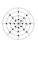
図11は、撮影条件選択部1184によって選択された撮影条件を、同一の照射角度を有し、撮影角度が互いに相違する撮影条件のグループに分類したときの1つのグループを説明するための模式図である。図11は、図5と同様に、製品150の検査対象とする部分領域151を中心とし、製品150の上面に平行な赤道面を有する仮想的な半球体に経度線と緯度線を描画したものを上から見た図である。説明を簡略化するために、経度線と緯度線は粗い間隔で描画している。また、図11において、照明器122を配置する箇所には白い丸印を描き、高速カメラ121を配置する箇所には黒い丸印を描いている。
FIG. 11 is a schematic diagram for explaining one group when the imaging conditions selected by the imaging
次に高速カメラ画像取得部1185は、上記グループ毎に、ロボットアーム制御部1182を制御することによって照射角度を当該グループの照射角度に固定した状態で、高速カメラ121と製品150との相対的な移動量が最小となるように、選択された撮影条件のそれぞれの撮影角度に切り替える順番を決定する。例えば、図11に示されるグループの場合、高速カメラ画像取得部1185は、例えば図12に示すような順番で各交点を移動するような高速カメラ121の移動経路を決定する。
Next, the high-speed camera
次に高速カメラ画像取得部1185は、上記グループ毎に、常に半球体の中心方向に撮影方向が向くようにしながら上記決定した移動経路上を高速カメラ121が移動するようにロボットアーム制御部1182を制御する。そして、高速カメラ画像取得部1185は、撮影角度が撮影条件の撮影角度に一致するタイミング(即ち、高速カメラ121が交点を通過するタイミング)で、高速カメラ121のシャッターを切ることによって製品150の部分領域151の画像を取得する。例えば、図12に示すような移動経路が決定された場合、高速カメラ画像取得部1185は、ロボットアーム制御部1182を制御することによって照明器122を図12の白い丸印の箇所に固定した状態で、ロボットアーム制御部1182を制御することによって高速カメラ121を上記移動経路に沿って移動させる。そして、高速カメラ画像取得部1185は、高速カメラ121が図12の黒い丸印の箇所を通過するタイミングでカメラのシャッターを切る。
Next, the high-speed camera
高速カメラ画像取得部1185は、上記グループを処理する順番は、照明器122と製品150との相対的な移動量が最小となるように決定する。例えば、高速カメラ画像取得部1185は、照明器122と製品150との相対的な移動量が最小となるように、照明器122の移動経路を決定し、該決定した移動経路に従って、照明器122の位置(即ち、次に処理するグループ)を決定する。
The high-speed camera
<動作例2>
高速カメラ画像取得部1185は、撮影条件選択部1184によって選択された撮影条件を、同一の撮影角度(即ち、高速カメラ121の位置)を有し、照射角度(即ち、同一の照明器122の位置)が互いに相違する撮影条件のグループに分類する。<Operation example 2>
The high-speed camera
図13は、撮影条件選択部1184によって選択された撮影条件を、同一の撮影角度を有し、照射角度が互いに相違する撮影条件のグループに分類したときの1つのグループを説明するための模式図である。図13において、照明器122を配置する箇所には白い丸印を描き、高速カメラ121を配置する箇所には黒い丸印を描いている。
FIG. 13 is a schematic diagram for explaining one group when the imaging conditions selected by the imaging
次に高速カメラ画像取得部1185は、上記グループ毎に、ロボットアーム制御部1182を制御することによって撮影角度を当該グループの撮影角度に固定した状態で、照明器122と製品150との相対的な移動量が最小となるように、選択された撮影条件のそれぞれの照射角度に切り替える順番を決定する。例えば、図13に示されるグループの場合、高速カメラ画像取得部1185は、例えば図14に示すような順番で各交点を移動するような照明器122の移動経路を決定する。
Next, the high-speed camera
次に高速カメラ画像取得部1185は、上記グループ毎に、常に半球体の中心方向に照射方向が向くようにしながら上記決定した移動経路上を照明器122が移動するようにロボットアーム制御部1182を制御する。そして、高速カメラ画像取得部1185は、照射角度が撮影条件の照射角度に一致するタイミング(即ち、照明器122が交点を通過するタイミング)で、高速カメラ121のシャッターを切ることによって製品150の部分領域151の画像を取得する。例えば、図14に示すような移動経路が決定された場合、高速カメラ画像取得部1185は、ロボットアーム制御部1182を制御することによって高速カメラ121を図14の黒い丸印の箇所に固定した状態で、ロボットアーム制御部1182を制御することによって照明器122を上記移動経路に沿って移動させる。そして、高速カメラ画像取得部1185は、照明器122が図14の白い丸印の箇所を通過するタイミングで高速カメラ121のシャッターを切る。
Next, the high-speed camera
高速カメラ画像取得部1185は、上記グループを処理する順番は、高速カメラ121と製品150との相対的な移動量が最小となるように決定する。例えば、高速カメラ画像取得部1185は、高速カメラ121と製品150との相対的な移動量が最小となるように、高速カメラ121の移動経路を決定し、該決定した移動経路に従って、高速カメラ121の位置(即ち、次に処理するグループ)を決定する。
The high-speed camera
以上説明したように、本実施形態によれば、製品150の表面に疵などの異常がないかどうかを精度良く検査することができる。その理由は、製品150を照明する方向や撮影する方向の違う様々な撮影条件の下で製品150を撮影した画像に基づいて、検査を行うためである。このため、予め定められた一方向の照明、カメラ姿勢で行う検査に比較して、微細な疵などの異常を高精度に検出することができる。
As described above, according to the present embodiment, it is possible to accurately inspect the surface of the
また本実施形態によれば、撮影条件の種類が増えても、検査に要する時間が比例的に増大するのを防止することができる。その理由は、各撮影条件の下で取得された画像から検査に適する画像を選択し、その選択された画像の撮影条件の有効度をインクリメントしていくことによって、検査に適する撮影条件を学習し、学習後は、撮影条件毎の有効度に基づいて初期の様々な撮影条件から検査に適する1または複数の撮影条件を選択するためである。また、製品150の検査面の異常を検出するためのカメラとして、毎秒当たりの撮影可能画像数が多い高速カメラ121を使用しているため、撮影条件を次々と高速に切り替えながら製品150の検査面を撮影することができるためである。また本実施形態によれば、所定の条件が成立するまでに実施する対象物の検査において、様々な撮影条件の下で検査しながら、有効度を更新しているため、検査前に実施する事前調整が不要になる。
Further, according to this embodiment, even if the number of types of imaging conditions increases, it is possible to prevent the time required for inspection from increasing proportionally. The reason for this is that the imaging conditions suitable for inspection are learned by selecting images suitable for inspection from the images acquired under each imaging condition and incrementing the effectiveness of the imaging conditions of the selected images. This is because, after learning, one or a plurality of imaging conditions suitable for inspection are selected from various initial imaging conditions based on the effectiveness of each imaging condition. In addition, since the high-
本実施形態は、以下のような各種の付加変更が可能である。 The present embodiment can be modified in various ways as follows.
本実施形態では、撮影条件は、検査対象となる製品150の部分領域に対する高速カメラ121の撮影方向(撮影角度)および照明器122の照明方向(照射角度)の2つのパラメータで定まるものとした。しかし、撮影条件は、撮影角度および照射角度に加えてそれ以外の1以上のパラメータで定まるものであってもよい。他のパラメータとしては、照明光の強度がある。また、他のパラメータとしては、照明光の波長帯、間接照明の有無、直接照明の有無などが考えられる。
In this embodiment, the imaging conditions are determined by two parameters, the imaging direction (imaging angle) of the high-
また本実施形態では、製品150の検査面に対する高速カメラ121の撮影角度、照明器122の照射角度は、それらの位置と姿勢を変更することによって調整した。しかし、高速カメラ121と照明器122の位置と姿勢を固定し、製品150の姿勢を調整することによって、製品150の検査面に対する高速カメラ121の撮影角度、照明器122の照射角度を調整してもよい。或いは、高速カメラ121、照明器122、および製品150の位置と姿勢をそれぞれ変更するようにしてもよい。
Further, in this embodiment, the imaging angle of the high-
また本実施形態では、製品150の検査面の異常を検出するために高速カメラ120を使用したが、高速カメラ120の代わりに赤外線カメラなど他の種類のカメラを使用してもよい。
Also, in this embodiment, the high-
また本実施形態では、製品150の上面を複数に分割して得られた個々の部分領域毎に検査を行った。しかし、製品150の上面サイズが小さい場合には製品150の上面全体を1つの部分領域として検査を行うことができる。また、製品150の上面の一部の部分領域だけを検査することも可能である。また、その場合には、広角カメラ120を省略してもよい。
Further, in this embodiment, each partial area obtained by dividing the upper surface of the
[第2の実施の形態]
次に、本発明の第2の実施形態について図15を参照して説明する。図15は、本実施形態に係る検査装置200のブロック図である。なお、本実施形態は、本発明の検査装置の概略を説明する。[Second embodiment]
Next, a second embodiment of the invention will be described with reference to FIG. FIG. 15 is a block diagram of an
図15を参照すると、本実施形態に係る検査装置200は、変更手段201と撮影条件選択手段202と画像取得手段203と異常検出手段204と有効度更新手段205とを含んで構成されている。
Referring to FIG. 15, an
変更手段201は、対象物を撮影する条件を様々な撮影条件に変更するように構成されている。変更手段201は、例えば図1のロボットアーム131、132およびロボットアーム制御部1182と同様に構成することができるが、それに限定されない。
The changing means 201 is configured to change the conditions for photographing the object to various photographing conditions. The changing means 201 can be configured in the same manner as the robot arms 131 and 132 and the
撮影条件選択手段202は、所定の条件が成立するまでに実施する対象物の検査では、様々な撮影条件の全てを選択し、所定の条件が成立した後に実施する対象物の検査では、撮影条件毎の有効度に基づいて様々な撮影条件から1または複数の撮影条件を選択するように構成されている。撮影条件選択手段202は、例えば図1の撮影条件選択部1184と同様に構成することができるが、それに限定されない。
The imaging
画像取得手段203は、変更手段201を制御することによって、選択された撮影条件のそれぞれの下で対象物の画像を取得するように構成されている。画像取得手段203は、例えば図1の高速カメラ画像取得部1185と同様に構成することができるが、それに限定されない。
The image acquiring means 203 is configured to acquire an image of the object under each of the selected imaging conditions by controlling the changing
異常検出手段204は、画像取得手段203によって取得された画像に基づいて対象物の異常を検出するように構成されている。異常検出手段204は、例えば図2の異常検出部1186と同様に構成することができるが、それに限定されない。
The abnormality detection means 204 is configured to detect an abnormality of the object based on the image acquired by the image acquisition means 203 . The abnormality detection means 204 can be configured, for example, in the same manner as the
有効度更新手段205は、画像取得手段203によって取得された画像に基づいて有効度を更新するように構成されている。具体的には、有効度更新手段205は、画像取得手段203によって取得された画像のうち、検査に適する画像を撮影したときの撮影条件の有効度が検査に適さない撮影条件と比較してより有効になるように有効度を更新するように構成されている。有効度更新手段205は、例えば図2の有効度更新部1187と同様に構成することができるが、それに限定されない。
The effectiveness update means 205 is configured to update the effectiveness based on the image acquired by the image acquisition means 203 . Specifically, the
このように構成された検査装置200は以下のように動作する。即ち、先ず、撮影条件選択手段202は、所定の条件が成立するまでに実施する対象物の検査では、様々な撮影条件の全てを選択し、所定の条件が成立した後に実施する対象物の検査では、撮影条件毎の有効度に基づいて様々な撮影条件から1または複数の撮影条件を選択する。次に、画像取得手段203は、変更手段201を制御することによって、撮影条件選択手段202によって選択された撮影条件のそれぞれの下で対象物の画像を取得する。次に、異常検出手段204は、画像取得手段203によって取得された画像に基づいて対象物の異常を検出する。また、有効度更新手段205は、画像取得手段203によって取得された画像に基づいて有効度を更新する。
The
本実施形態は以上のように構成され動作することにより、検査の高精度化、平均検査時間の短縮、および、事前調整コストの削減が行える。その理由は、検査装置200は、所定の条件が成立するまでに実施する対象物の検査では、様々な撮影条件の全てを選択し、所定の条件が成立した後に実施する対象物の検査では、撮影条件毎の有効度に基づいて様々な撮影条件から1または複数の撮影条件を選択するためである。即ち、検査の高精度化が実現できる理由は、所定の条件が成立するまでに実施する対象物の検査では、様々な撮影条件の下で検査し、所定の条件が成立した後に実施する対象物の検査では、それまでに実施された検査で更新された有効度に基づいて検査に適する撮影条件の下で検査が行われるためである。また、平均検査時間が短縮される理由は、所定の条件が成立した後に実施する対象物の検査では、それまでに実施された検査で更新された有効度に基づいて検査に適する撮影条件の下で検査が行われるためである。また、事前調整コストが削減される理由は、所定の条件が成立するまでに実施する対象物の検査において、様々な撮影条件の下で検査しながら、有効度を更新しているため、事前調整が不要になるためである。
By configuring and operating as described above, this embodiment can improve the accuracy of inspection, shorten the average inspection time, and reduce the preliminary adjustment cost. The reason for this is that the
以上、上記各実施形態を参照して本発明を説明したが、本発明は、上述した実施形態に限定されるものではない。本発明の構成や詳細には、本発明の範囲内で当業者が理解しうる様々な変更をすることができる。 Although the present invention has been described with reference to the above-described embodiments, the present invention is not limited to the above-described embodiments. Various changes can be made to the configuration and details of the present invention within the scope of the present invention that can be understood by those skilled in the art.
本発明は、工業製品や部品などの対象物の疵などを検査する分野全般に利用できる。 INDUSTRIAL APPLICABILITY The present invention can be used in general fields for inspecting objects such as industrial products and parts for defects.
上記の実施形態の一部又は全部は、以下の付記のようにも記載され得るが、以下には限られない。
[付記1]
対象物を撮影する条件を様々な撮影条件に変更する変更手段と、
所定の条件が成立するまでに実施する対象物の検査では、前記様々な撮影条件の全てを選択し、前記所定の条件が成立した後に実施する対象物の検査では、前記撮影条件毎の有効度に基づいて前記様々な撮影条件から1または複数の撮影条件を選択する撮影条件選択手段と、
前記変更手段を制御することによって、前記選択された撮影条件のそれぞれの下で前記対象物の画像を取得する画像取得手段と、
前記取得された画像に基づいて前記対象物の異常を検出する異常検出手段と、
前記取得された画像に基づいて前記有効度を更新する有効度更新手段と、
を備える検査装置。
[付記2]
前記対象物に照明光を照射する照明手段と、
前記対象物の検査面を撮影する第1の撮像手段と、
をさらに備え、
前記変更手段は、前記対象物に対する前記照明光の照射角度および前記撮影の撮影角度を変更するように構成されている、
付記1に記載の検査装置。
[付記3]
前記画像取得手段は、前記第1の撮像手段と前記対象物との相対的な移動量が最小となるように、前記選択された撮影条件のそれぞれに切り替える順番を決定し、該決定した順番に従って前記変更手段を制御するように構成されている、
付記2に記載の検査装置。
[付記4]
前記画像取得手段は、前記照明手段と前記対象物との相対的な移動量が最小となるように、前記選択された撮影条件のそれぞれに切り替える順番を決定し、該決定した順番に従って前記変更手段を制御するように構成されている、
付記2または3に記載の検査装置。
[付記5]
前記画像取得手段は、前記選択された撮影条件を、同一の照射角度を有し撮影角度が互いに相違する撮影条件のグループに分類し、前記グループ毎に、前記変更手段を制御することによって前記照射角度を前記グループの照射角度に固定した状態で、前記変更手段を制御することによって前記撮影角度を連続的に変更し、前記撮影角度が前記撮影条件の撮影角度に一致するタイミングで前記第1の撮像手段によって前記検査面の画像を取得するように構成されている、
付記2乃至4の何れかに記載の検査装置。
[付記6]
前記画像取得手段は、前記選択された撮影条件を、同一の撮影角度を有し照射角度が互いに相違する撮影条件のグループに分類し、前記グループ毎に、前記変更手段を制御することによって前記撮影角度を前記グループの撮影角度に固定した状態で、前記変更手段を制御することによって前記照射角度を連続的に変更し、前記照射角度が前記撮影条件の照射角度に一致するタイミングで前記第1の撮像手段によって前記検査面の画像を取得するように構成されている、
付記2乃至4の何れかに記載の検査装置。
[付記7]
前記対象物を撮影する、前記第1の撮像手段より広角な第2の撮像手段を、さらに備え、
前記第1の撮像手段は、前記第2の撮像手段で撮影された前記対象物の画像を複数に分割して得られる個々の分割領域を撮影するように構成されている、
付記2乃至6の何れかに記載の検査装置。
[付記8]
前記異常検出手段は、前記対象物の異常の検出結果を前記第2の撮像手段で撮影された画像中の対応する前記分割領域に表示するように構成されている、
付記7に記載の検査装置。
[付記9]
前記第1の撮像手段は、高速カメラである、
付記2乃至8の何れかに記載の検査装置。
[付記10]
所定の条件が成立するまでに実施する対象物の検査では、様々な撮影条件の全てを選択し、前記所定の条件が成立した後に実施する対象物の検査では、前記撮影条件毎の有効度に基づいて前記様々な撮影条件から1または複数の撮影条件を選択し、
前記選択された撮影条件のそれぞれの下で前記対象物の画像を取得し、
前記取得された画像に基づいて前記対象物の異常を検出し、
前記取得された画像に基づいて前記有効度を更新する、
検査方法。
[付記11]
コンピュータに、
所定の条件が成立するまでに実施する対象物の検査では、様々な撮影条件の全てを選択し、前記所定の条件が成立した後に実施する対象物の検査では、前記撮影条件毎の有効度に基づいて前記様々な撮影条件から1または複数の撮影条件を選択する処理と、
前記選択された撮影条件のそれぞれの下で前記対象物の画像を取得する処理と、
前記取得された画像に基づいて前記対象物の異常を検出する処理と、
前記取得された画像に基づいて前記有効度を更新する処理と、
を行わせるためのプログラムを記録するコンピュータ読み取り可能な記録媒体。Some or all of the above embodiments may also be described in the following additional remarks, but are not limited to the following.
[Appendix 1]
changing means for changing conditions for photographing an object to various photographing conditions;
All of the various imaging conditions are selected in the inspection of the object to be performed until a predetermined condition is satisfied, and the effectiveness of each of the imaging conditions is selected in the inspection of the object to be performed after the predetermined condition is satisfied. an imaging condition selection means for selecting one or more imaging conditions from the various imaging conditions based on
an image acquiring means for acquiring an image of the object under each of the selected imaging conditions by controlling the changing means;
Abnormality detection means for detecting an abnormality of the object based on the acquired image;
validity updating means for updating the validity based on the acquired image;
inspection device.
[Appendix 2]
illumination means for illuminating the object with illumination light;
a first imaging means for imaging an inspection surface of the object;
further comprising
The changing means is configured to change an irradiation angle of the illumination light and a photographing angle of the photographing with respect to the object.
The inspection device according to appendix 1.
[Appendix 3]
The image acquisition means determines the order of switching to each of the selected imaging conditions so that the amount of relative movement between the first imaging means and the object is minimized, and follows the determined order. configured to control the modifying means;
The inspection device according to appendix 2.
[Appendix 4]
The image acquisition means determines an order of switching to each of the selected photographing conditions so that the amount of relative movement between the illumination means and the object is minimized, and the change means follows the determined order. is configured to control the
The inspection device according to
[Appendix 5]
The image acquisition means classifies the selected imaging conditions into groups of imaging conditions having the same irradiation angle and different imaging angles, and controlling the irradiation means for each group. With the angle fixed to the irradiation angle of the group, the photographing angle is continuously changed by controlling the changing means, and the first photographing angle is set at the timing when the photographing angle matches the photographing angle of the photographing conditions. configured to acquire an image of the inspection surface by imaging means;
5. The inspection device according to any one of Appendices 2 to 4.
[Appendix 6]
The image acquisition means classifies the selected imaging conditions into groups of imaging conditions having the same imaging angle and different irradiation angles, and controls the changing means for each group to control the imaging conditions. The irradiation angle is continuously changed by controlling the changing means while the angle is fixed to the imaging angle of the group, and the first irradiation angle is changed at the timing when the irradiation angle matches the irradiation angle of the imaging conditions. configured to acquire an image of the inspection surface by imaging means;
5. The inspection device according to any one of Appendices 2 to 4.
[Appendix 7]
further comprising a second imaging means that is wider than the first imaging means for imaging the object;
The first image capturing means is configured to capture individual divided areas obtained by dividing the image of the object captured by the second image capturing means into a plurality of areas.
7. The inspection apparatus according to any one of Appendices 2 to 6.
[Appendix 8]
The abnormality detection means is configured to display a detection result of the abnormality of the object in the corresponding divided area in the image captured by the second imaging means.
The inspection device according to
[Appendix 9]
The first imaging means is a high-speed camera,
9. The inspection apparatus according to any one of Appendices 2 to 8.
[Appendix 10]
In the inspection of the object to be performed until a predetermined condition is satisfied, all of various imaging conditions are selected, and in the inspection of the object to be performed after the predetermined condition is satisfied, the effectiveness of each of the imaging conditions is selected. selecting one or more imaging conditions from the various imaging conditions based on
acquiring an image of the object under each of the selected imaging conditions;
detecting an abnormality of the object based on the acquired image;
updating the validity based on the acquired image;
Inspection methods.
[Appendix 11]
to the computer,
In the inspection of the object to be performed until a predetermined condition is satisfied, all of various imaging conditions are selected, and in the inspection of the object to be performed after the predetermined condition is satisfied, the effectiveness of each of the imaging conditions is selected. a process of selecting one or more imaging conditions from the various imaging conditions based on;
acquiring an image of the object under each of the selected imaging conditions;
A process of detecting an abnormality in the object based on the acquired image;
a process of updating the effectiveness based on the acquired image;
A computer-readable recording medium that records a program for performing
100…検査装置
110…コンピュータ
120…広角カメラ
121…高速カメラ
122…照明器
130~132…ロボットアーム
130a~132a…関節
130b~132b…アーム
140…ベルトコンベア
150…製品
151…部分領域DESCRIPTION OF SYMBOLS 100...
Claims (11)
前記部分領域画像に対応する部分領域毎に、様々な撮影条件と個々の前記撮影条件を一意に識別する撮影条件IDとが事前に設定された学習前撮影条件テーブル中の前記様々な撮影条件の下で、前記第1の撮像手段よりも挟角な第2の撮像手段を用いて撮影された前記部分領域の画像を挟角部分領域画像として取得する高速カメラ画像取得手段と、
前記部分領域毎に、前記高速カメラ画像取得手段によって取得された1以上の前記挟角部分領域画像の中から、検査に適する前記挟角部分領域画像を選択し、選択した前記挟角部分領域画像と当該挟角部分領域画像の撮影に使用された撮影条件IDとを含む検査画像を生成し、前記検査画像に基づいて前記製品の前記検査面の異常を検出する異常検出手段と、
前記部分領域毎に、前記検査画像に含まれる前記撮影条件IDに基づいて、前記様々な撮影条件それぞれについての有効度をインクリメントする有効度更新手段と、
前記部分領域毎に、所定の条件が成立したか否かを判定し、所定の条件が成立した部分領域については、前記様々な撮影条件のうち前記有効度が所定値以上である撮影条件IDに対応する撮影条件だけを設定した学習後撮影条件テーブルを生成する撮影条件選択手段と、
を備える検査装置。 wide-angle camera image acquisition means for dividing an image of an inspection surface of a product to be inspected captured by the first imaging means into a plurality of partial area images;
The various photographing conditions in a pre-learning photographing condition table in which various photographing conditions and a photographing condition ID uniquely identifying each photographing condition are set in advance for each partial region corresponding to the partial region image. high-speed camera image acquisition means for acquiring, as a narrow angle partial area image, an image of the partial area captured using a second imaging means having a narrower angle than the first imaging means;
selecting the narrow-angle partial area image suitable for inspection from among the one or more narrow-angle partial area images acquired by the high-speed camera image acquisition means for each of the partial areas, and selecting the narrow-angle partial area image; and an imaging condition ID used for imaging the narrow-angle partial area image, and detects an abnormality of the inspection surface of the product based on the inspection image;
effectiveness updating means for incrementing the effectiveness of each of the various imaging conditions based on the imaging condition ID included in the inspection image for each of the partial regions;
It is determined whether or not a predetermined condition is established for each of the partial areas, and for the partial area where the predetermined condition is established , the photographing condition ID having the validity level greater than or equal to a predetermined value among the various photographing conditions is assigned. an imaging condition selection means for generating a post-learning imaging condition table in which only corresponding imaging conditions are set;
inspection device.
前記座標値で特定される前記部分領域の中心をカメラ光軸が貫く撮影方向に前記第2の撮像手段で撮影した画像から、前記第1の撮像手段で撮影した部分領域の画像に対応する領域を前記挟角部分領域画像として抽出する、
請求項1に記載の検査装置。 The high-speed camera image acquisition means, in photographing the partial area specified by the coordinate values of the partial area,
A region corresponding to the image of the partial region captured by the first imaging device from the image captured by the second imaging device in the imaging direction in which the camera optical axis passes through the center of the partial region specified by the coordinate values. is extracted as the narrow-angle partial area image,
The inspection device according to claim 1.
請求項2に記載の検査装置。 In the extraction of the narrow-angle partial area image, the high-speed camera image acquisition means uses the image of the partial area captured by the first imaging means as a reference image, extracts a plurality of feature points from the reference image, The image captured by the imaging means of 2 is used as an original image, the corresponding points corresponding to the feature points are detected from the original image, and the original image is geometrically deformed so that the corresponding points and the feature points are superimposed. aligning the original image using the calculated projective transformation parameter, and converting an area corresponding to the reference image from the original image after alignment into the narrow angle partial area extract as an image,
The inspection device according to claim 2.
請求項1乃至3の何れかに記載の検査装置。 The imaging conditions include an imaging angle of the second imaging means and an illumination angle of a lighting device that illuminates the product.
The inspection device according to any one of claims 1 to 3.
請求項4に記載の検査装置。 The high-speed camera image acquisition means minimizes the amount of relative movement between the second imaging means and the product in the imaging of the partial area by the second imaging means under the various imaging conditions. to determine the order of the imaging conditions, and perform imaging by switching the imaging conditions in order according to the determined order;
The inspection device according to claim 4.
請求項4に記載の検査装置。 The high-speed camera image acquisition means minimizes the amount of relative movement between the lighting device and the product when the second imaging means captures the partial area under the various imaging conditions. determining the order of the imaging conditions, and performing imaging by switching the imaging conditions in order according to the determined order;
The inspection device according to claim 4.
請求項4に記載の検査装置。 The high-speed camera image acquisition means, in the photographing of the partial area by the second imaging means under the various photographing conditions, the various photographing conditions having the same irradiation angle and different photographing angles. The imaging conditions are classified into groups, and for each group, the imaging angle is continuously changed while the irradiation angle is fixed to the irradiation angle of the group, and the imaging angle matches the imaging angle of the group. capturing an image of the partial area by the second imaging means at the timing;
The inspection device according to claim 4.
請求項4に記載の検査装置。 The high-speed camera image acquisition means is adapted to capture the partial area by the second imaging means under the various shooting conditions, and the various shooting conditions have the same shooting angle and different illumination angles. Classifying into groups of photographing conditions, continuously changing the lighting angle while fixing the photographing angle to the photographing angle of the group for each group, and making the lighting angle match the lighting angle of the group. capturing an image of the partial area by the second imaging means at the timing;
The inspection device according to claim 4.
請求項1乃至8の何れかに記載の検査装置。 The high-speed camera image acquisition means uses the post-learning photographing condition table instead of the pre-learning photographing condition table in subsequent product inspections for the partial region for which the post-learning photographing condition table has been generated. ,
The inspection device according to any one of claims 1 to 8.
現に検査を行う製品を位置決めする処理と、
前記位置決めされた製品の検査を行う面全体を、広角な第1の撮像手段で撮影する処理と、
前記第1の撮像手段で撮影して得られた前記面全体の画像を前記面全体を複数の領域に分割して得られる複数の部分領域に1対1に対応する複数の広角部分領域画像に分割し、前記広角部分領域画像と前記部分領域の座標値と前記部分領域のIDとの組を前記部分領域毎に有する広角カメラ画像を生成する処理と、
前記部分領域毎に、様々な撮影条件と個々の前記撮影条件を一意に識別する撮影条件IDとが事前に設定された学習前撮影条件テーブル中の前記様々な撮影条件の下で、前記第1の撮像手段よりも挟角な第2の撮像手段を用いて、前記位置決めされた製品の検査を行う面上の前記部分領域の座標値で特定される部分領域を撮影する処理と、
前記部分領域毎に、前記第2の撮像手段で撮影して得られた1以上の前記部分領域の画像である挟角部分領域画像の中から、検査に適する挟角部分領域画像を選択し、前記選択した挟角部分領域画像と当該挟角部分領域画像の撮影に使用された撮影条件IDとを含む検査画像を生成する処理と、
前記検査画像に基づいて前記位置決めされた製品の検査面の異常を検出する処理と、
前記位置決めされた製品の検査終了時に、前記部分領域毎に、前記検査画像に含まれる前記撮影条件IDに基づいて、前記様々な撮影条件それぞれの有効度をインクリメントする処理と
前記部分領域毎に、学習の終了条件が成立したか否かを判定し、学習の終了条件が成立した部分領域については、前記様々な撮影条件のうち前記有効度が所定値以上である撮影条件IDに対応する撮影条件だけを設定した学習後撮影条件テーブルを生成する処理と、
を含み、
前記学習後撮影条件テーブルが生成されている前記部分領域については、以後の製品の検査では、前記学習前撮影条件テーブルの代わりに前記学習後撮影条件テーブルを使用する、
検査方法。 An inspection method for sequentially inspecting a plurality of products produced by the same manufacturing process,
the process of locating the product currently being inspected;
a process of photographing the entire surface of the positioned product to be inspected by a wide-angle first imaging means;
The image of the entire surface obtained by photographing by the first imaging means is converted into a plurality of wide-angle partial area images corresponding one-to-one to the plurality of partial areas obtained by dividing the entire surface into a plurality of areas. a process of dividing and generating a wide-angle camera image having, for each partial area, a set of the wide-angle partial area image, the coordinate value of the partial area, and the ID of the partial area;
Under the various photographing conditions in a pre-learning photographing condition table in which various photographing conditions and photographing condition IDs uniquely identifying individual photographing conditions are set in advance for each of the partial areas, the first a process of photographing a partial area specified by the coordinate values of the partial area on the surface on which the positioned product is to be inspected, using a second imaging means having a narrower angle than the imaging means of
selecting a narrow-angle partial area image suitable for inspection from narrow-angle partial area images, which are images of one or more partial areas obtained by photographing the partial area by the second imaging means, for each of the partial areas; a process of generating an inspection image including the selected narrow-angle partial area image and a photographing condition ID used for photographing the narrow-angle partial area image;
a process of detecting an abnormality in the inspection surface of the positioned product based on the inspection image;
at the end of inspection of the positioned product, a process of incrementing the effectiveness of each of the various imaging conditions based on the imaging condition ID included in the inspection image for each partial area; , determines whether or not a learning end condition is satisfied, and for a partial region for which the learning end condition is satisfied , an image capturing condition corresponding to the image capturing condition ID whose effectiveness is equal to or greater than a predetermined value among the various image capturing conditions. a process of generating a post-learning imaging condition table in which only conditions are set;
including
For the partial region for which the post-learning imaging condition table has been generated, the post-learning imaging condition table is used instead of the pre-learning imaging condition table in subsequent product inspections.
Inspection methods.
現に検査を行う製品を位置決めする処理と、
前記位置決めされた製品の検査を行う面全体を、広角な第1の撮像手段で撮影する処理と、
前記第1の撮像手段で撮影して得られた前記面全体の画像を前記面全体を複数の領域に分割して得られる複数の部分領域に1対1に対応する複数の広角部分領域画像に分割し、前記広角部分領域画像と前記部分領域の座標値と前記部分領域のIDとの組を前記部分領域毎に有する広角カメラ画像を生成する処理と、
前記部分領域毎に、様々な撮影条件と個々の前記撮影条件を一意に識別する撮影条件IDとが事前に設定された学習前撮影条件テーブル中の前記様々な撮影条件の下で、前記第1の撮像手段よりも挟角な第2の撮像手段を用いて、前記位置決めされた製品の検査を行う面上の前記部分領域の座標値で特定される部分領域を撮影する処理と、
前記部分領域毎に、前記第2の撮像手段で撮影して得られた1以上の前記部分領域の画像である挟角部分領域画像の中から、検査に適する挟角部分領域画像を選択し、前記選択した挟角部分領域画像と当該挟角部分領域画像の撮影に使用された撮影条件IDとを含む検査画像を生成する処理と、
前記検査画像に基づいて前記位置決めされた製品の検査面の異常を検出する処理と、
前記位置決めされた製品の検査終了時に、前記部分領域毎に、前記検査画像に含まれる前記撮影条件IDに基づいて、前記様々な撮影条件それぞれの有効度をインクリメントする処理と、
前記部分領域毎に、学習の終了条件が成立したか否かを判定し、学習の終了条件が成立した部分領域については、前記様々な撮影条件のうち前記有効度が所定値以上である撮影条件IDに対応する撮影条件だけを設定した学習後撮影条件テーブルを生成する処理と、
を行わせるためのプログラムであって、
前記学習後撮影条件テーブルが生成されている前記部分領域については、以後の製品の検査では、前記学習前撮影条件テーブルの代わりに前記学習後撮影条件テーブルを使用する、
プログラム。 A computer that sequentially inspects multiple products produced by the same manufacturing process,
the process of locating the product currently being inspected;
a process of photographing the entire surface of the positioned product to be inspected by a wide-angle first imaging means;
The image of the entire surface obtained by photographing by the first imaging means is converted into a plurality of wide-angle partial area images corresponding one-to-one to the plurality of partial areas obtained by dividing the entire surface into a plurality of areas. a process of dividing and generating a wide-angle camera image having, for each partial area, a set of the wide-angle partial area image, the coordinate value of the partial area, and the ID of the partial area;
Under the various photographing conditions in a pre-learning photographing condition table in which various photographing conditions and photographing condition IDs uniquely identifying individual photographing conditions are set in advance for each of the partial areas, the first a process of photographing a partial area specified by the coordinate values of the partial area on the surface on which the positioned product is to be inspected, using a second imaging means having a narrower angle than the imaging means of
selecting a narrow-angle partial area image suitable for inspection from narrow-angle partial area images, which are images of one or more partial areas obtained by photographing the partial area by the second imaging means, for each of the partial areas; a process of generating an inspection image including the selected narrow-angle partial area image and a photographing condition ID used for photographing the narrow-angle partial area image;
a process of detecting an abnormality in the inspection surface of the positioned product based on the inspection image;
a process of incrementing the effectiveness of each of the various imaging conditions based on the imaging condition ID included in the inspection image for each partial region at the end of inspection of the positioned product;
For each of the partial areas, it is determined whether or not a learning end condition is satisfied, and for the partial area for which the learning end condition is satisfied, a photographing condition in which the degree of effectiveness is equal to or greater than a predetermined value among the various photographing conditions . a process of generating a post-learning imaging condition table in which only the imaging conditions corresponding to the ID are set;
A program for performing
For the partial region for which the post-learning imaging condition table has been generated, the post-learning imaging condition table is used instead of the pre-learning imaging condition table in subsequent product inspections.
program.
Applications Claiming Priority (1)
| Application Number | Priority Date | Filing Date | Title |
|---|---|---|---|
| PCT/JP2019/012994 WO2020194541A1 (en) | 2019-03-26 | 2019-03-26 | Inspection device |
Publications (2)
| Publication Number | Publication Date |
|---|---|
| JPWO2020194541A1 JPWO2020194541A1 (en) | 2020-10-01 |
| JP7151873B2 true JP7151873B2 (en) | 2022-10-12 |
Family
ID=72609412
Family Applications (1)
| Application Number | Title | Priority Date | Filing Date |
|---|---|---|---|
| JP2021508497A Active JP7151873B2 (en) | 2019-03-26 | 2019-03-26 | inspection equipment |
Country Status (3)
| Country | Link |
|---|---|
| US (1) | US11933739B2 (en) |
| JP (1) | JP7151873B2 (en) |
| WO (1) | WO2020194541A1 (en) |
Families Citing this family (5)
| Publication number | Priority date | Publication date | Assignee | Title |
|---|---|---|---|---|
| EP3886428A1 (en) * | 2020-03-24 | 2021-09-29 | Canon Kabushiki Kaisha | System and edge device |
| JP7613996B2 (en) * | 2021-04-16 | 2025-01-15 | 株式会社キーエンス | Image inspection device, control unit for image inspection device, image inspection method, image inspection program, computer-readable recording medium, and device having the program recorded thereon |
| JP7548870B2 (en) * | 2021-05-28 | 2024-09-10 | 株式会社エデックリンセイシステム | Cylinder inner surface imaging device |
| JPWO2023157071A1 (en) * | 2022-02-15 | 2023-08-24 | ||
| GB202302413D0 (en) * | 2023-02-20 | 2023-04-05 | Univ Strathclyde | Anomaly capture system and process |
Citations (3)
| Publication number | Priority date | Publication date | Assignee | Title |
|---|---|---|---|---|
| JP2002162368A (en) | 2000-09-13 | 2002-06-07 | Nikon Corp | Surface inspection apparatus and method |
| JP2006322731A (en) | 2005-05-17 | 2006-11-30 | Olympus Corp | Visual inspection device |
| JP2008298693A (en) | 2007-06-01 | 2008-12-11 | Panasonic Corp | Inspection condition determination method |
Family Cites Families (8)
| Publication number | Priority date | Publication date | Assignee | Title |
|---|---|---|---|---|
| KR100795286B1 (en) | 2000-03-24 | 2008-01-15 | 올림푸스 가부시키가이샤 | Apparatus for detecting defect |
| JP2003270163A (en) * | 2002-03-15 | 2003-09-25 | Dainippon Printing Co Ltd | Inspection method and apparatus |
| JP2005091049A (en) | 2003-09-12 | 2005-04-07 | Ccs Inc | Light irradiator for image processing and light irradiation method for image processing |
| JP2006300775A (en) * | 2005-04-21 | 2006-11-02 | Olympus Corp | Visual inspection device |
| JP4673733B2 (en) | 2005-12-02 | 2011-04-20 | 新日本製鐵株式会社 | Surface inspection apparatus and surface inspection method |
| KR20070106428A (en) | 2006-04-28 | 2007-11-01 | 가부시끼가이샤 도시바 | Verification device and verification method of recording medium |
| JP2007298381A (en) * | 2006-04-28 | 2007-11-15 | Toshiba Corp | Image detection apparatus and image detection method |
| JP5843241B2 (en) * | 2013-11-26 | 2016-01-13 | レーザーテック株式会社 | Inspection apparatus and inspection method |
-
2019
- 2019-03-26 JP JP2021508497A patent/JP7151873B2/en active Active
- 2019-03-26 US US17/439,514 patent/US11933739B2/en active Active
- 2019-03-26 WO PCT/JP2019/012994 patent/WO2020194541A1/en not_active Ceased
Patent Citations (3)
| Publication number | Priority date | Publication date | Assignee | Title |
|---|---|---|---|---|
| JP2002162368A (en) | 2000-09-13 | 2002-06-07 | Nikon Corp | Surface inspection apparatus and method |
| JP2006322731A (en) | 2005-05-17 | 2006-11-30 | Olympus Corp | Visual inspection device |
| JP2008298693A (en) | 2007-06-01 | 2008-12-11 | Panasonic Corp | Inspection condition determination method |
Also Published As
| Publication number | Publication date |
|---|---|
| US11933739B2 (en) | 2024-03-19 |
| WO2020194541A1 (en) | 2020-10-01 |
| JPWO2020194541A1 (en) | 2020-10-01 |
| US20220155238A1 (en) | 2022-05-19 |
Similar Documents
| Publication | Publication Date | Title |
|---|---|---|
| JP7151873B2 (en) | inspection equipment | |
| JP5947169B2 (en) | Appearance inspection apparatus, appearance inspection method and program | |
| JP6408259B2 (en) | Image inspection apparatus, image inspection method, image inspection program, computer-readable recording medium, and recorded apparatus | |
| US9292925B2 (en) | Imaging system and control method thereof | |
| KR101590831B1 (en) | Method of inspecting foreign substance on a board | |
| JP2015232485A (en) | Image inspection device, image inspection method, image inspection program and computer readable recording medium, and apparatus having image inspection program recorded therein | |
| JP6140255B2 (en) | Image processing apparatus and image processing method | |
| CN119554980B (en) | Multi-vision automobile flange plate thread detection device and method based on mechanical arm | |
| JP5824278B2 (en) | Image processing device | |
| KR101522312B1 (en) | Inspection device for pcb product and inspecting method using the same | |
| WO2014208193A1 (en) | Wafer appearance inspection device | |
| JP6568991B2 (en) | Image inspection apparatus, image inspection method, image inspection program, computer-readable recording medium, and recorded apparatus | |
| JP2009080004A (en) | Inspection device | |
| JP6835020B2 (en) | Image processing system, image processing device, image processing program | |
| US20250200868A1 (en) | Methods, systems, and media for generating images of multiple sides of an object | |
| JP6704336B2 (en) | Inspection device and inspection method | |
| JP2006276454A (en) | Image correction method and pattern defect inspection method using the same | |
| TWI755460B (en) | Appearance inspection method | |
| JP2019158711A (en) | Image processing system, image processing device, and image processing program | |
| JP2006145228A (en) | Nonuniformity defect detection method and apparatus | |
| CN112710662A (en) | Generation method and device, generation system and storage medium | |
| JP7306620B2 (en) | Surface defect inspection device and surface defect inspection method | |
| KR910007348B1 (en) | Machine vision process and apparatus for reading a plurality of separated figures | |
| JP5947168B2 (en) | Appearance inspection apparatus, control method and program for appearance inspection apparatus | |
| JPS61156485A (en) | Slice level determining method of visual device |
Legal Events
| Date | Code | Title | Description |
|---|---|---|---|
| A521 | Request for written amendment filed |
Free format text: JAPANESE INTERMEDIATE CODE: A523 Effective date: 20210916 |
|
| A621 | Written request for application examination |
Free format text: JAPANESE INTERMEDIATE CODE: A621 Effective date: 20210916 |
|
| A131 | Notification of reasons for refusal |
Free format text: JAPANESE INTERMEDIATE CODE: A131 Effective date: 20220628 |
|
| A521 | Request for written amendment filed |
Free format text: JAPANESE INTERMEDIATE CODE: A523 Effective date: 20220810 |
|
| TRDD | Decision of grant or rejection written | ||
| A01 | Written decision to grant a patent or to grant a registration (utility model) |
Free format text: JAPANESE INTERMEDIATE CODE: A01 Effective date: 20220830 |
|
| A61 | First payment of annual fees (during grant procedure) |
Free format text: JAPANESE INTERMEDIATE CODE: A61 Effective date: 20220912 |
|
| R151 | Written notification of patent or utility model registration |
Ref document number: 7151873 Country of ref document: JP Free format text: JAPANESE INTERMEDIATE CODE: R151 |