JP7145018B2 - Fuel injection control device for internal combustion engine - Google Patents
Fuel injection control device for internal combustion engine Download PDFInfo
- Publication number
- JP7145018B2 JP7145018B2 JP2018173489A JP2018173489A JP7145018B2 JP 7145018 B2 JP7145018 B2 JP 7145018B2 JP 2018173489 A JP2018173489 A JP 2018173489A JP 2018173489 A JP2018173489 A JP 2018173489A JP 7145018 B2 JP7145018 B2 JP 7145018B2
- Authority
- JP
- Japan
- Prior art keywords
- temperature
- fuel
- internal combustion
- combustion engine
- fuel injection
- Prior art date
- Legal status (The legal status is an assumption and is not a legal conclusion. Google has not performed a legal analysis and makes no representation as to the accuracy of the status listed.)
- Active
Links
Images


Classifications
-
- Y—GENERAL TAGGING OF NEW TECHNOLOGICAL DEVELOPMENTS; GENERAL TAGGING OF CROSS-SECTIONAL TECHNOLOGIES SPANNING OVER SEVERAL SECTIONS OF THE IPC; TECHNICAL SUBJECTS COVERED BY FORMER USPC CROSS-REFERENCE ART COLLECTIONS [XRACs] AND DIGESTS
- Y02—TECHNOLOGIES OR APPLICATIONS FOR MITIGATION OR ADAPTATION AGAINST CLIMATE CHANGE
- Y02T—CLIMATE CHANGE MITIGATION TECHNOLOGIES RELATED TO TRANSPORTATION
- Y02T10/00—Road transport of goods or passengers
- Y02T10/10—Internal combustion engine [ICE] based vehicles
- Y02T10/40—Engine management systems
Landscapes
- Combined Controls Of Internal Combustion Engines (AREA)
- Electrical Control Of Air Or Fuel Supplied To Internal-Combustion Engine (AREA)
Description
本発明は、内燃機関の燃料噴射制御装置に関し、詳しくは、燃料カットを制御する技術に関する。 TECHNICAL FIELD The present invention relates to a fuel injection control device for an internal combustion engine, and more particularly to technology for controlling fuel cut.
特許文献1の制御装置は、エタノール単体の燃料やエタノールとガソリンとの混合燃料が使用可能な多種燃料エンジンにおいて、空燃比フィードバック補正量、空燃比学習値、及び、アルコール濃度学習値に基づいて、オイルパン内でオイル希釈が生じているか否かを判定し、所定の燃料カット条件が成立した場合に行われる燃料カットを、オイル希釈が生じていると判定したときに禁止する。
The control device of
内燃機関の潤滑油に燃料が混入するオイル希釈が発生すると、潤滑油に混入した燃料は、ブローバイ処理装置によってオイルパンから燃焼室に導かれる。
ここで、燃料噴射装置による燃料噴射及び点火装置による点火が行われる運転状態であれば、ブローバイ処理装置によって燃焼室に導かれた燃料は燃焼室内で燃焼する。
When oil dilution occurs in which fuel mixes with the lubricating oil of the internal combustion engine, the fuel mixed with the lubricating oil is guided from the oil pan to the combustion chamber by the blow-by processing device.
Here, in an operating state in which fuel is injected by the fuel injection device and ignition is performed by the ignition device, the fuel guided to the combustion chamber by the blow-by processing device burns in the combustion chamber.
一方、燃料カット中は、燃料噴射装置による燃料噴射及び点火装置による点火が停止され、ブローバイ処理装置によって燃焼室に導かれた燃料は、燃焼することなくそのまま排気系に流出する。そして、排気系に流出した燃料は、排気浄化装置の触媒で後燃えし、触媒温度を過剰に上昇させ、触媒を損傷させる可能性がある。
ここで、オイル希釈が発生しているときに燃料カットを禁止すれば、燃料の後燃えによる触媒温度の上昇を抑止できるが、燃料カットによる燃費の改善効果を得ることができなくなってしまう。
On the other hand, during the fuel cut, the fuel injection by the fuel injection device and the ignition by the ignition device are stopped, and the fuel guided to the combustion chamber by the blow-by processing device flows out to the exhaust system as it is without burning. Then, the fuel that has flowed out to the exhaust system may afterburn in the catalyst of the exhaust purification device, excessively increase the temperature of the catalyst, and damage the catalyst.
Here, if fuel cut is prohibited when oil dilution occurs, it is possible to suppress the increase in catalyst temperature due to afterburning of fuel, but the effect of improving fuel consumption by fuel cut cannot be obtained.
潤滑油に混入した燃料は、機関を継続運転させることで蒸発し、ブローバイ処理装置によって燃焼室内に導かれるが、潤滑油への新たな燃料の混入が生じるなどしてオイル希釈状態が維持される場合があるため、オイル希釈の発生状態で燃料カットを禁止すると、次のオイル交換まで燃料カットを禁止してしまう可能性があった。 The fuel mixed in the lubricating oil evaporates as the engine continues to operate, and is led into the combustion chamber by the blow-by treatment device. Therefore, if the fuel cut is prohibited when the oil is diluted, there is a possibility that the fuel cut will be prohibited until the next oil change.
本発明は、従来の実情に鑑みてなされたものであり、その目的は、オイル希釈状態で触媒温度の上昇を抑止しながら燃料カットを実施させることができる、内燃機関の燃料噴射制御装置を提供することにある。 SUMMARY OF THE INVENTION It is an object of the present invention to provide a fuel injection control device for an internal combustion engine that can cut fuel while suppressing an increase in catalyst temperature in an oil-diluted state. to do.
本発明の一態様によると、燃料噴射制御装置は、燃料カットを開始するときに、触媒の温度が高いほど燃料噴射装置による燃料噴射を再開させる機関回転速度である復帰回転速度を高く設定し、かつ、内燃機関の潤滑油への燃料の混入度合であるオイル希釈度合が大きいほど前記復帰回転速度を高く設定し、前記燃料カットの開始後に機関回転速度が前記復帰回転速度にまで低下すると前記燃料噴射装置による燃料噴射を再開させる。 According to one aspect of the present invention, when starting a fuel cut, the fuel injection control device sets a higher return rotation speed, which is an engine rotation speed at which fuel injection by the fuel injection device is restarted, as the temperature of the catalyst increases, and Further, the higher the degree of oil dilution, which is the degree of mixing of fuel into the lubricating oil of the internal combustion engine, the higher the return rotation speed is set. Resume fuel injection by the injector.
上記発明によると、オイル希釈状態において、触媒温度の上昇を抑止しながら燃料カットを実施でき、触媒を保護しつつ燃費を可及的に向上させることができる。 According to the above invention, in an oil-diluted state, fuel cut can be performed while suppressing an increase in catalyst temperature, and fuel consumption can be improved as much as possible while protecting the catalyst.
以下に本発明の実施の形態を説明する。
図1は、本発明に係る燃料噴射制御装置を適用する、内燃機関の一態様を示す構成図である。
図1に示す内燃機関1は、車両用の火花点火ガソリン機関であり、機関本体1aに点火装置4、燃料噴射装置の一態様である燃料噴射弁5を備える。
Embodiments of the present invention will be described below.
FIG. 1 is a configuration diagram showing one aspect of an internal combustion engine to which a fuel injection control device according to the present invention is applied.
An
燃料噴射弁5は、吸気管2aに配置され、吸気バルブ19を指向して燃料を吸気管2a内に噴射する。つまり、図1に示す内燃機関1は、燃料噴射弁5が吸気管2a内に燃料を噴射する所謂ポート噴射式内燃機関である。
但し、内燃機関1は、燃料噴射弁5が燃焼室10内に直接燃料を噴射する所謂筒内直接噴射式内燃機関であってもよい。
The
However, the
内燃機関1の吸入空気は、エアークリーナ7を通過し、電制スロットル8のスロットルバルブ8aで流量を調節された後、燃料噴射弁5が吸気管2a内に噴射する燃料と混合して燃焼室10に流入する。
電制スロットル8は、スロットルモータ8bでスロットルバルブ8aを開閉する装置であり、スロットルバルブ8aの開度であるスロットル開度TPSに応じた信号を出力するスロットル開度センサ8cを備える。
The intake air of the
The electronically controlled
回転数検出装置6(クランク角センサ)は、リングギア14の突起を検出することで、クランクシャフト17の所定回転角毎に回転角POSの信号を出力する。
水温センサ15は、機関本体1aが備えるウォータジャケット18に循環する冷却水の温度(以下、水温TWと称する)に応じた信号を出力する。
The rotation speed detection device 6 (crank angle sensor) detects the protrusion of the
The
流量検出装置9(エアーフローセンサ)は、電制スロットル8の上流側に配置され、内燃機関1の吸入空気流量QARに応じた信号を出力する。
また、排気浄化装置12(触媒コンバータ)は、排気管3aに配置され、内蔵する三元触媒などの触媒12aによって内燃機関1の排気を浄化する。
The flow rate detection device 9 (air flow sensor) is arranged upstream of the electronically controlled
Further, the exhaust purification device 12 (catalytic converter) is arranged in the exhaust pipe 3a and purifies the exhaust gas of the
空燃比センサ11は、排気浄化装置12の上流側の排気管3aに配置され、排気空燃比RABFに応じた信号を出力する。
また、触媒温度検出器の一態様である触媒温度センサ16は、排気浄化装置12の触媒12aの温度TCAT(℃)に応じた信号を出力する。
The air-
A
マイクロコンピュータを内蔵する電子制御装置(以下、ECU)13は、前述した各種センサが出力する、スロットル開度TPS、吸入空気流量QAR、回転角POS、水温TW、排気空燃比RABF、触媒温度TCATなどの検出信号を取り込む。
そして、燃料噴射制御装置の一態様であるECU13は、取り込んだ信号に基づき燃料噴射弁5を制御する機能をソフトウェアとして備える。
更に、ECU13は、点火装置4、電制スロットル8にも操作量を出力し、点火装置4による点火時期やスロットルバルブ8aの開度を制御して、内燃機関1の運転を制御する。
An electronic control unit (ECU) 13 incorporating a microcomputer controls throttle opening TPS, intake air flow QAR, rotation angle POS, water temperature TW, exhaust air-fuel ratio RABF, catalyst temperature TCAT, etc., which are output by the various sensors described above. captures the detection signal of
The ECU 13, which is one aspect of the fuel injection control device, has a function of controlling the
Further, the
ECU13は、各種センサの計測結果や各種装置に出力する操作量などのデータの入出力を行うために、アナログ入力回路20、A/D変換回路21、デジタル入力回路22、出力回路23及びI/O回路24を備える。
また、ECU13は、データの演算処理を行うために、MPU(Microprocessor Unit)26、ROM(Read Only Memory)27、RAM(Random Access Memory)28を含むマイクロコンピュータを備える。
The
The ECU 13 also includes a microcomputer including an MPU (Microprocessor Unit) 26, a ROM (Read Only Memory) 27, and a RAM (Random Access Memory) 28 in order to perform data arithmetic processing.
アナログ入力回路20には、吸入空気流量QAR、スロットル開度TPS、排気空燃比RABF、触媒温度TCAT、水温TWなどのセンサ検出信号が入力される。
A/D変換回路21は、アナログ入力回路20に入力された各種信号をデジタル信号に変換し、バス25上に出力する。
An
The A/
また、デジタル入力回路22に入力された回転角POSの信号は、I/O回路24を介してバス25上に出力される。
バス25には、MPU26、ROM27、RAM28、タイマ/カウンタ(TMR/CNT)29等が接続されている。そして、MPU26、ROM27、RAM28は、バス25を介してデータの授受を行う。
Also, the signal of the rotation angle POS input to the
MPU 26,
MPU26には、クロックジェネレータ30からクロック信号が供給され、MPU26は、クロック信号に同期して様々な演算や処理を実行する。
ROM27は、例えばデータの消去と書き換えが可能なEEPROM(Electrically Erasable Programmable Read-Only Memory)であり、ECU13を動作させるためのプログラム、設定データ及び初期値などを記憶する。
A clock signal is supplied from the
The
ROM27が記憶する情報は、バス25を介してRAM28及びMPU26に読み込まれる。
RAM28は、MPU26による演算結果や処理結果を一時的に記憶する作業領域として用いられる。
Information stored in the
The
なお、タイマ/カウンタ29は、時間の測定や様々な回数の測定などに用いられる。
MPU26による演算結果や処理結果は、バス25上に出力された後、I/O回路24を介して出力回路23から点火装置4、燃料噴射弁5、電制スロットル8などに供給される。
Note that the timer/
The calculation results and processing results by the
また、内燃機関1は、ブローバイガス処理装置41(ブローバイガス還流装置)を備える。ブローバイガス処理装置41は、内燃機関1の燃焼室10内から潤滑油を貯留するクランクケース42内に漏出した未燃燃料のうちの気化燃料を含むブローバイガスを内燃機関1の吸気系に戻す装置である。
ブローバイガス処理装置41は、クランクケース42内と吸気コレクタ部2b内とを連通させるブローバイガス還流通路43を有する。そして、クランクケース42内のブローバイガスは、ブローバイガス還流通路43を介してクランクケース42内から吸気コレクタ部2b内に還流し、ブローバイガス中の燃料は燃焼室10で燃焼する。
The
The blow-by
ECU13は、燃料噴射制御として、機関運転状態に基づき燃料噴射パルス幅TI(燃料噴射量)を演算し、気筒毎の噴射タイミングになると燃料噴射パルス幅TIの開弁パルス信号を燃料噴射弁5に出力する。燃料噴射弁5は、開弁パルス信号のオン期間で開弁し、開弁時間に比例する量の燃料を噴射する。
ここで、ECU13は、燃料噴射パルス幅TIの演算において、まず、内燃機関1の吸入空気量の計測値に基づいて基本燃料噴射パルス幅TP(基本燃料噴射量)を演算する。
As fuel injection control, the
Here, in calculating the fuel injection pulse width TI, the
また、ECU13は、基本燃料噴射パルス幅TPを補正するための空燃比補正係数KAFを、空燃比センサ11が検出する実空燃比を目標空燃比に近づけるように設定する、空燃比フィードバック制御を実施する。
更に、ECU13は、空燃比補正係数KAFによる補正量を機関運転領域毎に空燃比学習補正値LAFとして学習する。
そして、ECU13は、基本燃料噴射パルス幅TPを、空燃比補正係数KAF及び空燃比学習補正値LAFからなる空燃比補正量で補正して最終的な燃料噴射パルス幅TIを求める。
Further, the
Furthermore, the
Then, the
また、ECU13は、内燃機関1の運転状態が所定の燃料カット条件を満たすと、燃料噴射弁5による燃料噴射を一時的に停止させる燃料カットを実施する。
所定の燃料カット条件とは内燃機関1の所定減速運転状態であり、ECU13は、アクセル開度が全閉(アクセルオフ)になったときの機関回転速度NE(rpm)が燃料カット開始速度NESよりも高いと、燃料噴射弁5による燃料噴射を停止させる。
そして、ECU13は、燃料カット状態で、アクセルペダルが踏み込まれるか(アクセルオンになるか)、又は、機関回転速度NEが燃料噴射を再開させる復帰回転速度NER(NER<NES)にまで低下すると、燃料噴射弁5による燃料噴射を再開させる。
Further, when the operating state of the
The predetermined fuel cut condition is a predetermined deceleration operation state of the
Then, in the fuel cut state, the
更に、ECU13は、燃料カット状態から燃料噴射弁5による燃料供給を再開させる復帰条件である復帰回転速度NER(リカバリー回転速度)を、内燃機関1の潤滑油への燃料の混入度合であるオイル希釈度合に基づいて変更する機能を有する。
オイル希釈は、燃焼室10からオイルパン側に入り込んだ燃料が潤滑油に混入することで発生し、オイル希釈度合は、燃料噴射量における空燃比補正量の大きさから推定することができる。
Furthermore, the
Oil dilution occurs when fuel entering the oil pan side from the
潤滑油に混入する燃料(オイル希釈度合)が増えると、内燃機関1の暖機後に潤滑油中から揮発する燃料成分の量が増える。クランクケース42内で揮発した燃料成分は、ブローバイガス処理装置41によって吸気系に戻されるため、クランクケース42内で揮発する燃料成分が多くなると空燃比をリッチ化させることになり、空燃比フィードバック制御によって燃料噴射弁5から噴射させる燃料量を減らす補正量が多くなる。
したがって、ECU13は、燃料噴射量を減らす補正量の拡大からオイル希釈度合の増加を推定することができる。
As the amount of fuel mixed in the lubricating oil (degree of oil dilution) increases, the amount of fuel components volatilizing from the lubricating oil after the
Therefore, the
図2は、空燃比フィードバック制御による燃料噴射量の補正量(空燃比補正量)、及び、オイル希釈度合(オイル希釈レベル)と、内燃機関1の運転時間との相関を概略的に示す図である。
図2は、内燃機関1の運転時間が増すにしたがってオイル希釈度合が漸増し、オイル希釈度合が増大するにしたがって燃料噴射量を減らす補正量が拡大する特性を示す。
FIG. 2 is a diagram schematically showing the correlation between the correction amount of the fuel injection amount (air-fuel ratio correction amount) by air-fuel ratio feedback control, the oil dilution degree (oil dilution level), and the operating time of the
FIG. 2 shows characteristics in which the degree of oil dilution gradually increases as the operating time of the
ECU13は、上記特性に基づき、オイル交換直後に要求される燃料噴射量の補正量をベースとし、その後の運転時間の増加に応じた空燃比補正量の変化分からオイル希釈度合を推定することができる。係る構成であれば、内燃機関1の部品ばらつきや性能ばらつきによる空燃比補正量の違いに基づき、オイル希釈度合の推定精度が低下することを抑制できる。
また、ECU13は、内燃機関1が停止したときに空燃比補正量を記憶しておき、係る記憶値と再始動後の空燃比補正量とを比較することで、オイル交換による空燃比補正量のステップ的な変化を判断し、オイル交換が推定される場合は、そのときの空燃比補正量をベースとし、その後の空燃比補正量の変化分をオイル希釈による補正分としてオイル希釈度合を求めることができる。
Based on the characteristics described above, the
In addition, the
燃料カット中にブローバイガス処理装置41によって吸気系に戻る燃料は、燃焼することなくそのまま排気系に流出し、排気浄化装置12の触媒12aで後燃えすることで、触媒12aの温度を上昇させる。
このため、オイル希釈度合が高く、燃料カット中に多くの燃料がブローバイガス処理装置41によって吸気系に戻るときに、燃料カットを長い期間実施すると、触媒12aの温度が過剰に上昇して触媒12aを損傷させる可能性がある。
The fuel returned to the intake system by the blow-by
For this reason, when the degree of oil dilution is high and a large amount of fuel is returned to the intake system by the blow-by
一方、オイル希釈度合が比較的低い場合は、燃料カットを長い期間実施しても、触媒12aの温度上昇が抑えられ、長い期間に亘る燃料カットによって燃費を向上させることができる。
そこで、ECU13は、燃料カット状態からの復帰条件である復帰回転速度NERを、オイル希釈度合に基づいて変更することで、燃料カット中における触媒12aの温度上昇を許容温度内に抑制しつつ、可及的に長い期間に亘って燃料カットを実施して燃費改善の効果を最大限に得るようにする。
On the other hand, when the degree of oil dilution is relatively low, even if the fuel cut is performed for a long period of time, the temperature rise of the
Therefore, the
図3のフローチャートは、燃料カット制御において復帰回転速度NERを変更する処理の手順を示す。
なお、図3のフローチャートに示すルーチンは、内燃機関1の運転状態が所定の減速運転状態で燃料カット条件を満たしたときに実施される。
The flowchart of FIG. 3 shows the procedure of processing for changing the return rotational speed NER in fuel cut control.
The routine shown in the flowchart of FIG. 3 is executed when the operating state of the
ECU13は、ステップS101で、燃料カットを開始すると、次のステップS102で、そのときの機関回転速度NE及び機関負荷(トルク)のデータを取得し、ステップS103で、取得した機関回転速度NE及び機関負荷のデータに基づいて燃料カット開始時点での触媒12aの温度TCAbを推定する。
After starting fuel cut in step S101, the
図4は、ECU13が温度TCAbの推定処理に用いるマップを示す。
ECU13は、機関回転速度NE及び機関負荷で区分される複数の領域毎に、各領域で内燃機関1が定常運転された場合の触媒12aの温度TCAbを記憶するマップ(図4参照)をメモリに格納してある。
そして、ECU13は、ステップS103で、図4のマップを参照して、燃料カット開始時点での機関回転速度NE及び機関負荷に対応する温度TCAbのデータを検索する。
FIG. 4 shows a map used by the
The
Then, in step S103, the
次に、ECU13は、ステップS104で、燃料カット状態での触媒12aの推定最高温度TCAmaxを求める。
燃料カット中にブローバイガス処理装置41によって吸気系に戻される燃料が触媒12aで後燃えすると触媒12aの温度が上昇し、過度な温度上昇は触媒12aを損傷させることになる。そこで、ECU13は、燃料カットによって触媒12aの温度がどの程度まで上昇するかを推定することで、燃料カットを通常に実施できるか否か、換言すれば、燃料カット時間を短縮する必要があるか否かを判断する。
Next, in step S104, the
If the fuel returned to the intake system by the blow-by
ECU13は、推定最高温度TCAmaxを、燃料カット開始時点での触媒12aの温度TCAb、及び、燃料カット開始時点からの触媒12aの温度上昇量ΔTCAに基づいて求める。
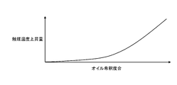
図5は、燃料カット開始時点からの触媒12aの温度上昇量ΔTCAと、オイル希釈度合との相関を示す。
The
FIG. 5 shows the correlation between the amount of temperature rise ΔTCA of the
図5は、オイル希釈度合が高いほど、燃料カット中に排気系に流出する燃料量が多くなって、触媒12aでの後燃えによる温度上昇量ΔTCAが大きくなるという特性を示す。
ECU13は、オイル希釈度合に応じた温度上昇量ΔTCAを図5のテーブルを参照して求め、燃料カット開始時点での触媒12aの温度TCAb(ベース温度)にオイル希釈度合に応じた温度上昇量ΔTCAを加算して、燃料カット状態での触媒12aの推定最高温度TCAmax(TCAmax=TCAb+ΔTCA)を求める。
FIG. 5 shows a characteristic that the higher the degree of oil dilution, the greater the amount of fuel that flows out into the exhaust system during fuel cut, and the greater the amount of temperature rise ΔTCA due to afterburning in the
The
ECU13は、次に、ステップS105で、推定最高温度TCAmaxと第1判定温度TCAT1とを比較する。
第1判定温度TCAT1は、推定最高温度TCAmaxの許容範囲の上限値であり、例えば950℃程度に設定される。
Next, in step S105, the
The first judgment temperature TCAT1 is the upper limit value of the allowable range of the estimated maximum temperature TCAmax, and is set to approximately 950° C., for example.
推定最高温度TCAmaxが第1判定温度TCAT1以下であることは、燃料カットを通常に実施しても、触媒12aの温度が触媒12aにダメージを与える温度に達しないことを示す。
そこで、ECU13は、推定最高温度TCAmaxが第1判定温度TCAT1以下である場合、ステップS106に進んで、復帰回転速度NERとして標準の復帰回転速度NERst(NERst<NES)を設定する。
The fact that the estimated maximum temperature TCAmax is equal to or lower than the first judgment temperature TCAT1 indicates that the temperature of the
Therefore, when the estimated maximum temperature TCAmax is equal to or lower than the first judgment temperature TCAT1, the
一方、推定最高温度TCAmaxが第1判定温度TCAT1を超える場合、ECU13は、ステップS107に進んで、推定最高温度TCAmaxと第2判定温度TCAT2とを比較する。なお、第2判定温度TCAT2は、第1判定温度TCAT1よりも高い温度であって(TCAT2>TCAT1)、第2判定温度TCAT2は、例えば1000℃程度に設定される。
第2判定温度TCAT2は、燃料カット期間を短縮することで、触媒12aの温度が触媒12aにダメージを与える温度に達することを抑止できる温度として設定される。
On the other hand, when the estimated maximum temperature TCAmax exceeds the first judgment temperature TCAT1, the
The second determination temperature TCAT2 is set as a temperature that can prevent the temperature of the
そして、ECU13は、推定最高温度TCAmaxが第2判定温度TCAT2を下回る場合、つまり、TCAT1<TCAmax<TCAT2が成立する場合、期間を短縮して燃料カットを実施させるためにステップS108に進む。
ECU13は、ステップS108で、復帰回転速度NERとして、標準の復帰回転速度NERstよりも高く、燃料カット開始速度NESよりも低い、燃料カット期間を短縮するための復帰回転速度NERshを設定する(NERst<NERs<NES)。
Then, when the estimated maximum temperature TCAmax is lower than the second judgment temperature TCAT2, that is, when TCAT1<TCAmax<TCAT2, the
In step S108, the
つまり、ECU13は、オイル希釈度合が高いほど温度上昇量ΔTCAを高く設定するので、オイル希釈度合が高いほど復帰回転速度NERをより高く変更することになる。
復帰回転速度NERshは復帰回転速度NERstよりも高いから、復帰回転速度NERshに基づく燃料噴射の再開は、復帰回転速度NERstに基づく燃料噴射の再開よりも早くなって、燃料カット期間(燃料カットの継続時間)が短くなる。
That is, the
Since the return rotation speed NERsh is higher than the return rotation speed NERst, the resumption of fuel injection based on the return rotation speed NERsh is earlier than the resumption of fuel injection based on the return rotation speed NERst. time) is shortened.
燃料カット期間が短くなれば、ブローバイガス処理装置41によって吸気系に戻された燃料が燃焼せずに排気系に流れて触媒12aで後燃えする期間(時間)が短くなり、燃料カット期間での触媒12aの温度上昇を許容範囲内(第1判定温度TCAT1以下)に抑えることが可能である。
また、期間を短縮しつつ燃料カットが実施されることで、燃料カットによる燃費改善の効果を得ることができる。
If the fuel cut period is shortened, the period (time) in which the fuel returned to the intake system by the blow-by
In addition, by executing the fuel cut while shortening the period, it is possible to obtain the effect of improving the fuel consumption due to the fuel cut.
なお、ECU13は、TCAT1<TCAmax<TCAT2が成立する場合に、第1判定温度TCAT1と第2判定温度TCAT2とで挟まれる温度域を複数に分け、前記温度域内で推定最高温度TCAmaxが高くなるほど、復帰回転速度NERを、標準の復帰回転速度NERstよりも高く設定することができる。
When TCAT1<TCAmax<TCAT2, the
一方、推定最高温度TCAmaxが第2判定温度TCAT2以上である場合は、燃料カットをある程度以上の期間実施しつつ、燃料カット期間での触媒12aの温度上昇を許容範囲内(第1判定温度TCAT1以下)に抑えることが難しい状態である。
そこで、ECU13は、推定最高温度TCAmaxが第2判定温度TCAT2以上である場合、ステップS107からステップS109に進み、燃料カットを禁止する。
これにより、燃料カットによる燃費改善の効果が削減されるものの、燃料カット中に触媒12aの温度が上昇して触媒12aが損傷することを抑止できる。
On the other hand, when the estimated maximum temperature TCAmax is equal to or higher than the second judgment temperature TCAT2, the fuel cut is performed for a certain period or longer, and the temperature rise of the
Therefore, when the estimated maximum temperature TCAmax is equal to or higher than the second judgment temperature TCAT2, the
As a result, although the effect of fuel consumption improvement due to the fuel cut is reduced, it is possible to prevent the temperature of the
図6は、オイル希釈度合、推定最高温度TCAmax、第1判定温度TCAT1、及び、第2判定温度TCAT2の相関を示す。
図6は、オイル希釈度合が高くなるほど燃料カット中の温度上昇量ΔTCAが高くなり、温度上昇量ΔTCAが高くなることで、第1判定温度TCAT1更には第2判定温度TCAT2を超える推定最高温度TCAmaxに達することを示す。
FIG. 6 shows the correlation among the degree of oil dilution, the estimated maximum temperature TCAmax, the first judgment temperature TCAT1, and the second judgment temperature TCAT2.
FIG. 6 shows that the higher the degree of oil dilution, the higher the temperature rise amount ΔTCA during fuel cut. is reached.
そして、ECU13は、オイル希釈度合が高く推定最高温度TCAmaxとしてより高い温度が設定されるときほど、復帰回転速度NERをより高く変更して燃料カット期間を短くするから、オイル希釈状態で触媒温度の上昇を抑止しながら燃料カットを可及的に実施させることができる。
また、図3のフローチャートに示す処理では、触媒温度センサ16の計測結果を用いないので、推定最高温度TCAmaxに基づく復帰回転速度NERの変更処理は、触媒温度センサ16を備えない内燃機関1にも適用可能であって汎用性が高い。
As the degree of oil dilution increases and a higher temperature is set as the estimated maximum temperature TCAmax, the
3 does not use the measurement result of the
ところで、図3のフローチャートに示した、オイル希釈度合に基づく復帰回転速度NERの変更処理の場合、ECU13は、燃料カット開始時点で推定した推定最高温度TCAmaxに基づき燃料カット期間を定めるが、その後に触媒温度センサ16が実測する触媒温度TCATに基づき、推定最高温度TCAmaxに基づく設定を変更することができる。
図7のフローチャートは、推定最高温度TCAmaxに基づき復帰条件を変更し、更に、推定最高温度TCAmaxに基づく復帰条件の設定を、触媒温度センサ16が実測する触媒温度TCATに基づいて変更する処理の手順を示す。
By the way, in the case of the process of changing the return rotational speed NER based on the degree of oil dilution shown in the flowchart of FIG. Based on the catalyst temperature TCAT actually measured by the
The flow chart of FIG. 7 shows the procedure for changing the return condition based on the estimated maximum temperature TCAmax, and changing the setting of the return condition based on the estimated maximum temperature TCAmax based on the catalyst temperature TCAT actually measured by the
図7のフローチャートにおいて、ECU13は、ステップS201-ステップS208の各ステップでは、図3のフローチャートのステップS101-ステップS108と同様な処理を実施するので、詳細な説明を省略する。
ECU13は、ステップS208で、復帰回転速度NERを、燃料カット期間を短縮するための復帰回転速度NERshに設定すると、次いで、ステップS209で、触媒温度センサ16の出力から実測最高温度TCATmaxを求める。
In the flowchart of FIG. 7, the
In step S208, the
つまり、実測最高温度TCATmaxは、燃料カット中にブローバイガス処理装置41によって吸気系に戻された燃料が燃焼せずに排気系にそのまま流れて触媒12aで後燃えしたことで上昇した触媒温度である。
そして、ECU13は、次のステップS210で、実測最高温度TCATmaxと第3判定温度TCAT3とを比較する。
In other words, the measured maximum temperature TCATmax is the catalyst temperature raised by the fact that the fuel returned to the intake system by the blow-by
Then, in the next step S210, the
第3判定温度TCAT3は、第1判定温度TCAT1以下、好ましくは第1判定温度TCAT1よりも低い温度とし(TCAT2>TCAT1≧TCAT3)、例えば、920℃程度に設定される。
そして、ECU13は、実測最高温度TCATmaxが第3判定温度TCAT3以下である場合、ステップS211に進み、機関回転速度NEが復帰回転速度NERstに低下するまで間で燃料カットを実施(再開)する。
The third judgment temperature TCAT3 is lower than the first judgment temperature TCAT1, preferably lower than the first judgment temperature TCAT1 (TCAT2>TCAT1≧TCAT3), and is set to about 920° C., for example.
If the measured highest temperature TCATmax is equal to or lower than the third judgment temperature TCAT3, the
復帰回転速度NERを標準の復帰回転速度NERstよりも高い復帰回転速度NERshに変更し、燃料カットを通常よりも短い期間で終了させる設定を行ったときに、ECU13は、実測最高温度TCATmaxと第3判定温度TCAT3とを比較する。
ここで、標準の復帰回転速度NERstによる燃料カット条件が成立する状態で実測最高温度TCATmaxが第3判定温度TCAT3以下であれば、推定最高温度TCAmaxによる燃料噴射の再開判定に優先して燃料カットを実施できることになる。
When the return rotational speed NER is changed to a higher return rotational speed NERsh than the standard return rotational speed NERst and the fuel cut is completed in a shorter period than usual, the
Here, if the measured maximum temperature TCATmax is equal to or lower than the third judgment temperature TCAT3 in a state where the fuel cut condition based on the standard return rotation speed NERst is established, the fuel cut is performed prior to the fuel injection restart determination based on the estimated maximum temperature TCAmax. can be implemented.
つまり、推定最高温度TCAmaxの推定誤差によって実際の温度上昇が推定最高温度TCAmaxよりも低く、復帰回転速度NERshにまで機関回転速度が低下し燃料噴射を再開させようとするときの実測最高温度TCATmaxが十分に低い場合、ECU13は、燃料カットを再開(継続)させる。
これにより、ECU13は、推定最高温度TCAmaxの推定誤差によって燃料カット期間を過剰に短縮してしまうことを抑止でき、燃料カットによる燃費改善の効果をより多く享受できる。
That is, due to an estimation error in the estimated maximum temperature TCAmax, the actual temperature rise is lower than the estimated maximum temperature TCAmax, and the actual measured maximum temperature TCATmax when the engine rotation speed is reduced to the return rotation speed NERsh and the fuel injection is to be restarted is If it is sufficiently low, the
As a result, the
また、ECU13は、推定最高温度TCAmaxが第2判定温度TCAT2以上である場合、ステップS207からステップS212に進み、燃料カットを禁止する。
次いで、ECU13は、ステップS213で、触媒温度センサ16の出力から実測最高温度TCATmaxを求める。
Further, when the estimated maximum temperature TCAmax is equal to or higher than the second judgment temperature TCAT2, the
Next, the
そして、ECU13は、次のステップS214で、実測最高温度TCATmaxと第3判定温度TCAT3とを比較する。
ここで、ECU13は、実測最高温度TCATmaxが第3判定温度TCAT3以下である場合、ステップS215に進み、機関回転速度NEが復帰回転速度NERstにまで低下する間で燃料カットを実施(再開)する。
Then, in the next step S214, the
Here, when the measured maximum temperature TCATmax is equal to or lower than the third determination temperature TCAT3, the
つまり、ECU13は、推定最高温度TCAmaxに基づき燃料カットを禁止したものの、実測最高温度TCATmaxが十分に低い場合は、燃料カットを実施(再開)させる。
これにより、ECU13は、推定最高温度TCAmaxの推定誤差によって燃料カットを不必要に禁止してしまうことを抑止でき、燃料カットによる燃費改善の効果をより多く享受できる。
That is, the
As a result, the
なお、本発明は、上記した実施形態に限定するものではなく、様々な変形例を含む。例えば、上記した実施形態は本発明を分かりやすく説明するために詳細に説明したものであり、必ずしも説明した全ての構成を備えるものに限定しない。
また、ある実施形態の構成の一部を他の実施形態の構成に置き換えることが可能であり、また、ある実施形態の構成に他の実施形態の構成を加えることも可能である。また、各実施形態の構成の一部について、他の構成の追加・削除・置換をすることが可能である。
In addition, the present invention is not limited to the above-described embodiments, and includes various modifications. For example, the above-described embodiments have been described in detail in order to explain the present invention in an easy-to-understand manner, and are not necessarily limited to those having all the described configurations.
Also, part of the configuration of one embodiment can be replaced with the configuration of another embodiment, and the configuration of another embodiment can be added to the configuration of one embodiment. Moreover, it is possible to add, delete, or replace part of the configuration of each embodiment with another configuration.
例えば、ECU13は、オイル希釈度合が閾値を超えるときに限定して、推定最高温度TCAmaxを求め、求めた推定最高温度TCAmaxに基づき復帰回転速度NER(復帰条件)を変更することができる。
また、ECU13は、内燃機関1が触媒温度センサ16を備える場合は、推定最高温度TCAmaxを求める処理を省略し、燃料カット開始後に触媒温度センサ16が検出する触媒温度TCATを監視し、触媒温度TCATが設定温度を超えるとき若しくは設定温度を超えると推定されるときに燃料カットを中断する、換言すれば、触媒温度TCATが設定温度を超えるとき若しくは設定温度を超えると推定されるときに復帰回転速度NER(復帰条件)をより高く変更することができる。
For example, the
Further, when the
また、ECU13は、触媒温度センサ16による計測値に基づき、オイル希釈度合と推定最高温度TCAmaxとの相関を学習することができる。
また、ECU13は、オイル希釈度合の推定処理として、公知の推定方法を適宜採用することができ、例えば、ECU13は、オイル交換後の内燃機関1の運転時間からオイル希釈度合を推定することができる。
Further, the
In addition, the
1…内燃機関、5…燃料噴射弁(燃料噴射装置)、12…排気浄化装置、12a…触媒、13…ECU(燃料噴射制御装置)、16…触媒温度センサ(触媒温度検出器)、41…ブローバイガス処理装置
DESCRIPTION OF
Claims (5)
前記燃料カットを開始するときに、前記触媒の温度が高いほど前記燃料噴射装置による燃料噴射を再開させる機関回転速度である復帰回転速度を高く設定し、かつ、前記内燃機関の潤滑油への燃料の混入度合であるオイル希釈度合が大きいほど前記復帰回転速度を高く設定し、
前記燃料カットの開始後に機関回転速度が前記復帰回転速度にまで低下すると前記燃料噴射装置による燃料噴射を再開させる、
内燃機関の燃料噴射制御装置。 Applied to the internal combustion engine provided with a fuel injection device for injecting fuel into the internal combustion engine and an exhaust purification device disposed in the exhaust system of the internal combustion engine and purifying exhaust gas with a catalyst , wherein the operating state of the internal combustion engine is fuel A fuel injection control device for an internal combustion engine that performs a fuel cut to stop fuel injection by the fuel injection device when a cut condition is satisfied ,
When starting the fuel cut, the higher the temperature of the catalyst, the higher the return rotation speed, which is the engine rotation speed at which the fuel injection by the fuel injection device is restarted, and the fuel to the lubricating oil of the internal combustion engine. The higher the degree of oil dilution, which is the degree of mixing of the oil, the higher the return rotation speed is set,
resuming fuel injection by the fuel injection device when the engine rotation speed decreases to the return rotation speed after the start of the fuel cut ;
A fuel injection control device for an internal combustion engine.
前記燃料カットを開始するときの前記触媒の温度と、前記オイル希釈度合に基づき求められる前記燃料カットの開始時点からの前記触媒の温度上昇量とから、前記燃料カットの実施状態での前記触媒の最高温度を推定し、前記最高温度が高いときほど前記復帰回転速度をより高く設定する、
内燃機関の燃料噴射制御装置。 A fuel injection control device for an internal combustion engine according to claim 1,
From the temperature of the catalyst when the fuel cut is started and the amount of temperature rise of the catalyst from the start time of the fuel cut, which is obtained based on the degree of oil dilution, the temperature of the catalyst when the fuel cut is performed. estimating the maximum temperature, and setting the return rotation speed higher as the maximum temperature is higher ;
A fuel injection control device for an internal combustion engine.
前記内燃機関は、前記触媒の温度を検出する触媒温度検出器を備え、
前記復帰回転速度を標準値よりも高く変更したときに、前記触媒温度検出器が検出する前記触媒の温度が所定温度以下であるときは、前記機関回転速度が前記標準値に低下するまで前記燃料カットを継続させる、
内燃機関の燃料噴射制御装置。 A fuel injection control device for an internal combustion engine according to claim 1,
The internal combustion engine includes a catalyst temperature detector that detects the temperature of the catalyst,
If the temperature of the catalyst detected by the catalyst temperature detector is equal to or lower than a predetermined temperature when the return rotational speed is changed higher than the standard value, the fuel is supplied until the engine rotational speed decreases to the standard value. continue cutting
A fuel injection control device for an internal combustion engine.
前記最高温度が第1判定温度以下であるときは、前記復帰回転速度を第1復帰回転速度に設定し、
前記最高温度が前記第1判定温度を超え、かつ、前記第1判定温度よりも高い第2判定温度よりも低いときは、前記復帰回転速度を前記第1復帰回転速度よりも高い第2復帰回転速度に設定し、
前記最高温度が前記第2判定温度以上であるときは、前記燃料カットを禁止する、
内燃機関の燃料噴射制御装置。 A fuel injection control device for an internal combustion engine according to claim 2,
when the maximum temperature is equal to or lower than the first judgment temperature, setting the return rotation speed to the first return rotation speed;
When the maximum temperature exceeds the first determination temperature and is lower than a second determination temperature higher than the first determination temperature, the return rotation speed is set to a second return rotation higher than the first return rotation speed. set to speed,
Prohibiting the fuel cut when the maximum temperature is equal to or higher than the second determination temperature;
A fuel injection control device for an internal combustion engine.
前記内燃機関は、前記触媒の温度を検出する触媒温度検出器を備え、
前記復帰回転速度を前記第2復帰回転速度に設定したときに、前記触媒温度検出器が検出する前記触媒の温度が、前記第1判定温度以下である第3判定温度以下であるときは、前記機関回転速度が前記第1復帰回転速度に低下するまで前記燃料カットを継続させる、
内燃機関の燃料噴射制御装置。 A fuel injection control device for an internal combustion engine according to claim 4,
The internal combustion engine includes a catalyst temperature detector that detects the temperature of the catalyst,
When the temperature of the catalyst detected by the catalyst temperature detector is equal to or lower than the third judgment temperature which is equal to or lower than the first judgment temperature when the return rotation speed is set to the second return rotation speed, the Continuing the fuel cut until the engine rotation speed decreases to the first return rotation speed;
A fuel injection control device for an internal combustion engine.
Priority Applications (1)
| Application Number | Priority Date | Filing Date | Title |
|---|---|---|---|
| JP2018173489A JP7145018B2 (en) | 2018-09-18 | 2018-09-18 | Fuel injection control device for internal combustion engine |
Applications Claiming Priority (1)
| Application Number | Priority Date | Filing Date | Title |
|---|---|---|---|
| JP2018173489A JP7145018B2 (en) | 2018-09-18 | 2018-09-18 | Fuel injection control device for internal combustion engine |
Publications (2)
| Publication Number | Publication Date |
|---|---|
| JP2020045790A JP2020045790A (en) | 2020-03-26 |
| JP7145018B2 true JP7145018B2 (en) | 2022-09-30 |
Family
ID=69900952
Family Applications (1)
| Application Number | Title | Priority Date | Filing Date |
|---|---|---|---|
| JP2018173489A Active JP7145018B2 (en) | 2018-09-18 | 2018-09-18 | Fuel injection control device for internal combustion engine |
Country Status (1)
| Country | Link |
|---|---|
| JP (1) | JP7145018B2 (en) |
Families Citing this family (1)
| Publication number | Priority date | Publication date | Assignee | Title |
|---|---|---|---|---|
| GB2612131B (en) * | 2021-10-25 | 2024-01-03 | Jaguar Land Rover Ltd | Methods and apparatus for mitigating fuel in oil |
Citations (6)
| Publication number | Priority date | Publication date | Assignee | Title |
|---|---|---|---|---|
| JP2005016484A (en) | 2003-06-27 | 2005-01-20 | Toyota Motor Corp | Evaporative fuel processing equipment |
| JP2006233828A (en) | 2005-02-24 | 2006-09-07 | Fujitsu Ten Ltd | Fuel injection control device |
| JP2011122543A (en) | 2009-12-11 | 2011-06-23 | Toyota Motor Corp | Oil dilution decision device of internal combustion engine, and internal combustion engine control device |
| WO2013065149A1 (en) | 2011-11-02 | 2013-05-10 | トヨタ自動車株式会社 | Control device for internal-combustion engine |
| JP2017025800A (en) | 2015-07-23 | 2017-02-02 | 富士重工業株式会社 | Engine control device |
| JP2018047742A (en) | 2016-09-20 | 2018-03-29 | トヨタ自動車株式会社 | Control device for hybrid vehicle |
-
2018
- 2018-09-18 JP JP2018173489A patent/JP7145018B2/en active Active
Patent Citations (6)
| Publication number | Priority date | Publication date | Assignee | Title |
|---|---|---|---|---|
| JP2005016484A (en) | 2003-06-27 | 2005-01-20 | Toyota Motor Corp | Evaporative fuel processing equipment |
| JP2006233828A (en) | 2005-02-24 | 2006-09-07 | Fujitsu Ten Ltd | Fuel injection control device |
| JP2011122543A (en) | 2009-12-11 | 2011-06-23 | Toyota Motor Corp | Oil dilution decision device of internal combustion engine, and internal combustion engine control device |
| WO2013065149A1 (en) | 2011-11-02 | 2013-05-10 | トヨタ自動車株式会社 | Control device for internal-combustion engine |
| JP2017025800A (en) | 2015-07-23 | 2017-02-02 | 富士重工業株式会社 | Engine control device |
| JP2018047742A (en) | 2016-09-20 | 2018-03-29 | トヨタ自動車株式会社 | Control device for hybrid vehicle |
Also Published As
| Publication number | Publication date |
|---|---|
| JP2020045790A (en) | 2020-03-26 |
Similar Documents
| Publication | Publication Date | Title |
|---|---|---|
| JP5131362B2 (en) | Control device for internal combustion engine | |
| JP2009074426A (en) | Control device for internal combustion engine | |
| US20100043749A1 (en) | Ignition control system for internal combustion engines | |
| KR102474612B1 (en) | Method of nitrogen oxide in engine reflecting travel distance | |
| US8362405B2 (en) | Heater controller of exhaust gas sensor | |
| KR100443778B1 (en) | Control apparatus for cylinder injection type internal combustion engine | |
| JP6241147B2 (en) | Catalyst temperature estimation device for internal combustion engine | |
| JP4304468B2 (en) | Oil temperature estimation device for internal combustion engine | |
| JP6534864B2 (en) | Engine control device | |
| JP7145018B2 (en) | Fuel injection control device for internal combustion engine | |
| CN109690058B (en) | Control device and control method for internal combustion engine | |
| JP4557176B2 (en) | Catalyst early warm-up control device for internal combustion engine | |
| JP5556387B2 (en) | Control device for variable valve system | |
| JP3770417B2 (en) | Catalyst degradation detector | |
| JP4807359B2 (en) | Air-fuel ratio control device for internal combustion engine | |
| JP2005016396A (en) | Catalyst warm-up system for internal combustion engines | |
| JP2775676B2 (en) | Fuel supply control device for internal combustion engine | |
| JP4415803B2 (en) | Control device for internal combustion engine | |
| JP4115162B2 (en) | Exhaust gas purification control device for internal combustion engine | |
| JP4304463B2 (en) | Fuel injection control device for internal combustion engine | |
| JP2020045814A (en) | Fuel injection control device for internal combustion engine | |
| JP2004197693A (en) | Air-fuel ratio control device for internal combustion engine | |
| JP4361702B2 (en) | Control device for internal combustion engine | |
| JP2009168759A (en) | Exhaust gas sensor heater control device | |
| JP2007231861A (en) | Oil temperature estimation device for internal combustion engine |
Legal Events
| Date | Code | Title | Description |
|---|---|---|---|
| A621 | Written request for application examination |
Free format text: JAPANESE INTERMEDIATE CODE: A621 Effective date: 20210309 |
|
| A977 | Report on retrieval |
Free format text: JAPANESE INTERMEDIATE CODE: A971007 Effective date: 20220218 |
|
| A131 | Notification of reasons for refusal |
Free format text: JAPANESE INTERMEDIATE CODE: A131 Effective date: 20220301 |
|
| A521 | Request for written amendment filed |
Free format text: JAPANESE INTERMEDIATE CODE: A523 Effective date: 20220405 |
|
| TRDD | Decision of grant or rejection written | ||
| A01 | Written decision to grant a patent or to grant a registration (utility model) |
Free format text: JAPANESE INTERMEDIATE CODE: A01 Effective date: 20220823 |
|
| A61 | First payment of annual fees (during grant procedure) |
Free format text: JAPANESE INTERMEDIATE CODE: A61 Effective date: 20220916 |
|
| R150 | Certificate of patent or registration of utility model |
Ref document number: 7145018 Country of ref document: JP Free format text: JAPANESE INTERMEDIATE CODE: R150 |
|
| R250 | Receipt of annual fees |
Free format text: JAPANESE INTERMEDIATE CODE: R250 |