JP7107224B2 - Image processing device, image processing method, and program - Google Patents
Image processing device, image processing method, and program Download PDFInfo
- Publication number
- JP7107224B2 JP7107224B2 JP2018550127A JP2018550127A JP7107224B2 JP 7107224 B2 JP7107224 B2 JP 7107224B2 JP 2018550127 A JP2018550127 A JP 2018550127A JP 2018550127 A JP2018550127 A JP 2018550127A JP 7107224 B2 JP7107224 B2 JP 7107224B2
- Authority
- JP
- Japan
- Prior art keywords
- image
- viewpoint
- viewpoints
- images
- pixel
- Prior art date
- Legal status (The legal status is an assumption and is not a legal conclusion. Google has not performed a legal analysis and makes no representation as to the accuracy of the status listed.)
- Active
Links
Images


Classifications
-
- H—ELECTRICITY
- H04—ELECTRIC COMMUNICATION TECHNIQUE
- H04N—PICTORIAL COMMUNICATION, e.g. TELEVISION
- H04N13/00—Stereoscopic video systems; Multi-view video systems; Details thereof
- H04N13/20—Image signal generators
- H04N13/204—Image signal generators using stereoscopic image cameras
- H04N13/207—Image signal generators using stereoscopic image cameras using a single two-dimensional [2D] image sensor
- H04N13/232—Image signal generators using stereoscopic image cameras using a single two-dimensional [2D] image sensor using fly-eye lenses, e.g. arrangements of circular lenses
-
- H—ELECTRICITY
- H04—ELECTRIC COMMUNICATION TECHNIQUE
- H04N—PICTORIAL COMMUNICATION, e.g. TELEVISION
- H04N23/00—Cameras or camera modules comprising electronic image sensors; Control thereof
- H04N23/60—Control of cameras or camera modules
- H04N23/67—Focus control based on electronic image sensor signals
-
- G—PHYSICS
- G06—COMPUTING OR CALCULATING; COUNTING
- G06T—IMAGE DATA PROCESSING OR GENERATION, IN GENERAL
- G06T1/00—General purpose image data processing
-
- H—ELECTRICITY
- H04—ELECTRIC COMMUNICATION TECHNIQUE
- H04N—PICTORIAL COMMUNICATION, e.g. TELEVISION
- H04N13/00—Stereoscopic video systems; Multi-view video systems; Details thereof
- H04N13/20—Image signal generators
- H04N13/271—Image signal generators wherein the generated image signals comprise depth maps or disparity maps
-
- H—ELECTRICITY
- H04—ELECTRIC COMMUNICATION TECHNIQUE
- H04N—PICTORIAL COMMUNICATION, e.g. TELEVISION
- H04N13/00—Stereoscopic video systems; Multi-view video systems; Details thereof
- H04N13/20—Image signal generators
- H04N13/282—Image signal generators for generating image signals corresponding to three or more geometrical viewpoints, e.g. multi-view systems
-
- H—ELECTRICITY
- H04—ELECTRIC COMMUNICATION TECHNIQUE
- H04N—PICTORIAL COMMUNICATION, e.g. TELEVISION
- H04N23/00—Cameras or camera modules comprising electronic image sensors; Control thereof
- H04N23/60—Control of cameras or camera modules
-
- H—ELECTRICITY
- H04—ELECTRIC COMMUNICATION TECHNIQUE
- H04N—PICTORIAL COMMUNICATION, e.g. TELEVISION
- H04N5/00—Details of television systems
- H04N5/222—Studio circuitry; Studio devices; Studio equipment
- H04N5/262—Studio circuits, e.g. for mixing, switching-over, change of character of image, other special effects ; Cameras specially adapted for the electronic generation of special effects
- H04N5/2628—Alteration of picture size, shape, position or orientation, e.g. zooming, rotation, rolling, perspective, translation
Landscapes
- Engineering & Computer Science (AREA)
- Multimedia (AREA)
- Signal Processing (AREA)
- Physics & Mathematics (AREA)
- General Physics & Mathematics (AREA)
- Theoretical Computer Science (AREA)
- Image Processing (AREA)
- Studio Devices (AREA)
Description
本技術は、画像処理装置、画像処理方法、及び、プログラムに関し、特に、例えば所望の光学的効果が付与されたリフォーカスを実現することができるようにする画像処理装置、画像処理方法、及び、プログラムに関する。 The present technology relates to an image processing device, an image processing method, and a program, and in particular, an image processing device, an image processing method, and an image processing method capable of realizing refocusing with a desired optical effect, for example. Regarding the program.
複数の視点の画像から、例えばリフォーカスを行った画像、すなわち、光学系のフォーカスを変更して撮影を行ったような画像等を再構成するライトフィールド技術が提案されている(例えば非特許文献1を参照)。 A light field technique has been proposed for reconstructing, for example, a refocused image, that is, an image shot by changing the focus of an optical system, from images from a plurality of viewpoints (see, for example, Non-Patent Document 1).
例えば非特許文献1には、100台のカメラからなるカメラアレイを用いたリフォーカスの方法が記載されている。 For example, Non-Patent Document 1 describes a refocusing method using a camera array consisting of 100 cameras.
今後、リフォーカスについては、ユーザ等が所望する光学的効果が付与されたリフォーカスを実現することのニーズが高まることが予想される。 In the future, it is expected that there will be an increasing need for realizing refocusing with optical effects desired by users and the like.
本技術は、このような状況に鑑みてなされたものであり、所望の光学的効果が付与されたリフォーカスを実現することができるようにするものである。 The present technology has been made in view of such a situation, and enables realization of refocusing with a desired optical effect.
本技術の画像処理装置、又は、プログラムは、複数の視点の画像を取得する取得部と、前記複数の視点の画像を用いて所定の距離に合焦した処理結果画像を生成する集光処理を行う集光処理部とを備え、前記集光処理部は、所定のフィルタ効果を生じさせるゲインの分布に応じて前記視点ごとに設定された調整係数によって画素値が調整された前記複数の視点の画像を用いて前記集光処理を行う画像処理装置、又は、そのような画像処理装置として、コンピュータを機能させるためのプログラムである。 An image processing device or a program according to the present technology performs an acquisition unit that acquires images from a plurality of viewpoints, and a condensing process that generates a processed result image that is focused at a predetermined distance using the images from the plurality of viewpoints. and a condensing processing unit for performing a predetermined filter effect, wherein the condensing processing unit adjusts the pixel values of the plurality of viewpoints by adjusting coefficients set for each of the viewpoints in accordance with a gain distribution that produces a predetermined filter effect. An image processing device that performs the condensing process using an image, or a program for causing a computer to function as such an image processing device.
本技術の画像処理方法は、複数の視点の画像を取得することと、前記複数の視点の画像を用いて所定の距離に合焦した処理結果画像を生成する集光処理を行うこととを含み、前記集光処理を、所定のフィルタ効果を生じさせるゲインの分布に応じて前記視点ごとに設定された調整係数によって画素値が調整された前記複数の視点の画像を用いて行う画像処理方法である。 An image processing method according to the present technology includes acquiring images from a plurality of viewpoints, and performing light condensing processing to generate a processed result image focused at a predetermined distance using the images from the plurality of viewpoints. an image processing method in which the light collection processing is performed using images of the plurality of viewpoints, the pixel values of which are adjusted by adjustment coefficients set for each of the viewpoints according to a gain distribution that produces a predetermined filter effect. be.
本技術の画像処理装置、画像処理方法、及び、プログラムにおいては、複数の視点の画像が取得され、前記複数の視点の画像を用いて所定の距離に合焦した処理結果画像を生成する集光処理が行われる。この集光処理は、所定のフィルタ効果を生じさせるゲインの分布に応じて前記視点ごとに設定された調整係数によって画素値が調整された前記複数の視点の画像を用いて行われる。 In the image processing device, image processing method, and program of the present technology, images of a plurality of viewpoints are acquired, and the images of the plurality of viewpoints are used to condense light to generate a processed result image focused at a predetermined distance. processing takes place. This condensing process is performed using the images of the plurality of viewpoints whose pixel values are adjusted by adjustment coefficients set for each of the viewpoints according to a gain distribution that produces a predetermined filter effect .
なお、画像処理装置は、独立した装置であっても良いし、1つの装置を構成している内部ブロックであっても良い。 The image processing device may be an independent device, or may be an internal block forming one device.
また、プログラムは、伝送媒体を介して伝送することにより、又は、記録媒体に記録して、提供することができる。 Also, the program can be provided by transmitting it via a transmission medium or by recording it on a recording medium.
本技術によれば、所望の光学的効果が付与されたリフォーカスを実現することができる。 According to the present technology, refocusing with a desired optical effect can be realized.
なお、ここに記載された効果は必ずしも限定されるものではなく、本開示中に記載されたいずれかの効果であってもよい。 Note that the effects described here are not necessarily limited, and may be any of the effects described in the present disclosure.
<本技術を適用した画像処理システムの一実施の形態> <An embodiment of an image processing system to which the present technology is applied>
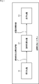
図1は、本技術を適用した画像処理システムの一実施の形態の構成例を示すブロック図である。 FIG. 1 is a block diagram showing a configuration example of an embodiment of an image processing system to which the present technology is applied.
図1において、画像処理システムは、撮影装置11、画像処理装置12、及び、表示装置13を有する。
In FIG. 1 , the image processing system has an
撮影装置11は、被写体を複数の視点から撮影し、その結果得られる複数の視点の、例えば(ほぼ)パンフォーカスの撮影画像を画像処理装置12に供給する。
The photographing
画像処理装置12は、撮影装置11からの複数の視点の撮影画像を用いて任意の被写体にフォーカスを合わせた画像を生成(再構成)するリフォーカス等の画像処理を行い、その画像処理の結果得られる処理結果画像を表示装置13に供給する。
The
表示装置13は、画像処理装置12からの処理結果画像を表示する。
The
なお、図1において、画像処理システムを構成する撮影装置11、画像処理装置12、及び、表示装置13は、それらのすべてを例えばディジタル(スチル/ビデオ)カメラや、スマートフォン等の携帯端末等のような独立した装置に内蔵させることができる。
In FIG. 1, the
また、撮影装置11、画像処理装置12、及び、表示装置13は、それぞれを別個に独立した装置に内蔵させることができる。
Further, the
さらに、撮影装置11、画像処理装置12、及び、表示装置13は、それらのうちの任意の2つと残りの1つとをそれぞれ別個に独立した装置に内蔵させることができる。
Furthermore, any two of the
例えば撮影装置11及び表示装置13をユーザが所持する携帯端末に内蔵させ、画像処理装置12をクラウド上のサーバに内蔵させることができる。
For example, the
また、画像処理装置12の一部のブロックをクラウド上のサーバに内蔵させ、画像処理装置12の残りのブロックと撮影装置11及び表示装置13とを携帯端末に内蔵させることができる。
Also, some blocks of the
<撮影装置11の構成例>
<Configuration example of
図2は、図1の撮影装置11の構成例を示す背面図である。
FIG. 2 is a rear view showing a configuration example of the photographing
撮影装置11は、例えばRGBの値を画素値として有する画像を撮影する複数のカメラユニット(以下、カメラともいう)21iを有し、その複数のカメラ21iによって、複数の視点の撮影画像を撮影する。The photographing
図2では、撮影装置11は、複数としての、例えば7個のカメラ211,212,213,214,215,216、及び、217を有し、それらの7個のカメラ211ないし217は、2次元平面上に配置されている。In FIG. 2, the
さらに、図2では、7個のカメラ211ないし217は、それらのうちの1つである、例えばカメラ211を中心として、他の6個のカメラ212ないし217が、カメラ211の周辺に正6角形を構成するように配置されている。Further, in FIG. 2, the seven cameras 21 1 to 21 7 are one of them, for example the camera 21 1 is the center, and the other six cameras 21 2 to 21 7 are the cameras 21 1 are arranged to form a regular hexagon around the .
したがって、図2では、7個のカメラ211ないし217のうちの、任意の1つのカメラ21i(i=1,2,...,7)とそのカメラ21iに最も近い他の1つのカメラ21j(j=1,2,...,7)との(光軸どうしの)距離は、同一の距離Bになっている。Therefore, in FIG. 2, any one of the seven cameras 21 1 to 21 7 , 21 i (i=1,2,...,7) and the other one closest to that camera 21 i The distances (between the optical axes) to the two cameras 21 j (j=1, 2, . . . , 7) are the same distance B.
カメラ21iと21jとの距離Bとしては、例えば20mm程度を採用することができる。この場合、撮影装置11は、ICカード等のカードサイズ程度の大きさに構成することができる。As the distance B between the cameras 21 i and 21 j , for example, about 20 mm can be adopted. In this case, the photographing
なお、撮影装置11を構成するカメラ21iの数は、7個に限定されるものではなく、2個以上6個以下の数や、8個以上の数を採用することができる。Note that the number of cameras 21i constituting the
また、撮影装置11において、複数のカメラ21iは、上述のような正6角形等の正多角形を構成するように配置する他、任意の位置に配置することができる。In addition, in the photographing
ここで、以下、カメラ211ないし217のうちの、中心に配置されたカメラ211を基準カメラ211ともいい、その基準カメラ211の周辺に配置されたカメラ212ないし217を周辺カメラ212ないし217ともいう。Here, of the cameras 21 1 to 21 7 , the camera 21 1 arranged in the center is hereinafter referred to as the reference camera 21 1 , and the cameras 21 2 to 21 7 arranged around the reference camera 21 1 are referred to as peripheral cameras 21 1 to 21 7 . Also referred to as cameras 21 2 to 21 7 .
図3は、図1の撮影装置11の他の構成例を示す背面図である。
FIG. 3 is a rear view showing another configuration example of the photographing
図3では、撮影装置11は、9個のカメラ2111ないし2119で構成され、その9個のカメラ2111ないし2119は、横×縦が3×3に配置されている。3×3のカメラ21i(i=11,12,...,19)は、上、下、左、又は、右に隣接するカメラ21j(j=11,12,...,19)と距離Bだけ離れて配置されている。In FIG. 3, the photographing
ここで、以下では、特に断らない限り、撮影装置11は、例えば図2に示したように、7個のカメラ211ないし217で構成されることとする。Here, hereinafter, unless otherwise specified, the photographing
また、基準カメラ211の視点を基準視点ともいい、基準カメラ211で撮影された撮影画像PL1を基準画像PL1ともいう。さらに、周辺カメラ21iで撮影された撮影画像PL#iを周辺画像PL#iともいう。Further, the viewpoint of the reference camera 21 1 is also called a reference viewpoint, and the photographed image PL1 captured by the reference camera 21 1 is also called a reference image PL1. Further, the captured image PL#i captured by the peripheral camera 21 i is also referred to as a peripheral image PL#i.
なお、撮影装置11は、図2や図3に示したように、複数のカメラ21iで構成する他、例えばRen.Ng、他7名,"Light Field Photography with a Hand-Held Plenoptic Camera", Stanford Tech Report CTSR 2005-02に記載されているように、MLA(Micro Lens Array)を用いて構成することができる。MLAを用いて撮影装置11を構成した場合であっても、実質的に、複数の視点から撮影した撮影画像を得ることができる。2 and 3, the photographing
また、複数の視点の撮影画像を撮影する方法は、撮影装置11を複数のカメラ21iで構成する方法や、MLAを用いて構成する方法に限定されるものではない。Further, the method of capturing captured images from a plurality of viewpoints is not limited to the method of configuring the
<画像処理装置12の構成例>
<Configuration example of
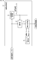
図4は、図1の画像処理装置12の構成例を示すブロック図である。
FIG. 4 is a block diagram showing a configuration example of the
図4において、画像処理装置12は、視差情報生成部31、補間部32、調整部33、集光処理部34、及び、パラメータ設定部35を有する。
In FIG. 4 , the
画像処理装置12には、撮影装置11から、カメラ211ないし217で撮影された7視点の撮影画像PL1ないしPL7が供給される。The photographed images PL1 to PL7 of seven viewpoints photographed by the cameras 21 1 to 21 7 are supplied from the photographing
画像処理装置12において、撮影画像PL#iは、視差情報生成部31、及び、補間部32に供給される。
In the
視差情報生成部31は、撮影装置11から供給される撮影画像PL#iを用いて視差情報を求め、補間部32、及び、集光処理部34に供給する。
The parallax
すなわち、視差情報生成部31は、例えば撮影装置11から供給される撮影画像PL#iそれぞれの、他の撮影画像PL#jとの視差情報を求める処理を複数の視点の撮影画像PL#iの画像処理として行う。そして、視差情報生成部31は、例えば撮影画像の画素(の位置)ごとに、視差情報が登録されたマップを生成し、補間部32、及び、集光処理部34に供給する。
That is, the parallax
ここで、視差情報としては、視差を画素数で表したディスパリティ(disparity)や、視差に対応する奥行き方向の距離等の視差に換算することができる任意の情報を採用することができる。本実施の形態では、視差情報として、例えばディスパリティを採用することとし、視差情報生成部31では、そのディスパリティが登録されたディスパリティマップが、視差情報が登録されたマップとして生成されることとする。
Here, as the parallax information, any information that can be converted into parallax, such as disparity that represents parallax by the number of pixels, or distance in the depth direction corresponding to parallax, can be adopted. In the present embodiment, for example, disparity is adopted as the parallax information, and the disparity map in which the disparity is registered is generated in the parallax
補間部32は、撮影装置11からの、カメラ211ないし217の7視点の撮影画像PL1ないしPL7と視差情報生成部31からのディスパリティマップとを用いてカメラ211ないし217の7視点以外の視点から撮影を行ったならば得られる画像を補間により生成する。The
ここで、後述する集光処理部34が行う集光処理によって、複数のカメラ211ないし217で構成される撮影装置11は、カメラ211ないし217を合成開口とする仮想レンズとして機能させることができる。図2の撮影装置11については、仮想レンズの合成開口は、周辺カメラ212ないし217の光軸を結ぶ、直径が略2Bの略円形状になる。Here, the photographing
補間部32は、例えば仮想レンズの直径2Bを一辺とする正方形(又は、仮想レンズの合成開口に内接する正方形)内のほぼ等間隔の複数の点、すなわち、例えば横×縦が21×21個の点を視点として、その21×21視点のうちの、カメラ211ないし217の7視点以外の、21×21-7視点の画像を補間により生成する。The
そして、補間部32は、カメラ211ないし217の7視点の撮影画像PL1ないしPL7と撮影画像を用いた補間により生成された21×21-7視点の画像とを調整部33に供給する。Then, the
ここで、補間部32において、撮影画像を用いた補間により生成された画像を補間画像ともいう。
Here, an image generated by interpolation using a photographed image in the
また、補間部32から調整部33に供給される、カメラ211ないし217の7視点の撮影画像PL1ないしPL7と21×21-7視点の補間画像との、合計で、21×21視点の画像を視点画像ともいう。In addition, the captured images PL1 to PL7 of the cameras 21 1 to 21 7 at the seven viewpoints and the interpolated images at the 21×21-7 viewpoints, which are supplied from the
補間部32での補間は、カメラ211ないし217の7視点の撮影画像PL1ないしPL7から、より多く数の視点(ここでは、21×21視点)の視点画像を生成する処理であると考えることができる。この多数の視点の視点画像を生成する処理は、実空間内の実空間点から、カメラ211ないし217を合成開口とする仮想レンズに入射する光線を再現する処理であると捉えることができる。Interpolation by the
調整部33には、補間部32から、複数の視点の視点画像が供給される他、パラメータ設定部35から、調整パラメータが供給される。調整パラメータは、例えば視点ごとに設定された、画素値を調整する調整係数である。
Viewpoint images of a plurality of viewpoints are supplied from the
調整部33は、パラメータ設定部35からの調整パラメータとしての視点ごとの調整係数によって、補間部32からの各視点の視点画像の画素の画素値を調整し、画素値の調整後の複数の視点の視点画像を集光処理部34に供給する。
The
集光処理部34は、調整部33からの複数の視点の視点画像を用いて、現実のカメラにおいて、レンズ等の光学系を通過した、被写体からの光線をイメージセンサやフィルム上に集光させ、被写体の像を形成することに相当する画像処理である集光処理を行う。
The light
集光処理部34の集光処理では、任意の被写体にフォーカスを合わせた画像を生成(再構成)するリフォーカスが行われる。リフォーカスは、視差情報生成部31からのディスパリティマップや、パラメータ設定部35からの集光パラメータを用いて行われる。
In the condensing processing of the condensing
集光処理部34の集光処理によって得られる画像は、処理結果画像として(表示装置13)に出力される。
An image obtained by the condensing processing of the condensing
パラメータ設定部35は、ユーザによる図示せぬ操作部の操作や、所定のアプリケーション等によって指定された位置にある、撮影画像PL#i(例えば基準画像PL1)の画素を、合焦させる(被写体が映る)合焦対象画素に設定し、集光パラメータ(の一部)として、集光処理部34に供給する。
The
さらに、パラメータ設定部35は、ユーザの操作や、所定のアプリケーションからの指令に従って、画素値を調整する調整係数を複数の視点のそれぞれごとに設定し、その視点ごとの調整係数を調整パラメータとして、調整部33に供給する。
Furthermore, the
調整パラメータは、調整部33での画素値の調整を制御するパラメータであり、集光処理部34での集光処理に用いられる視点画像の視点、すなわち、補間部32で得られる視点画像の視点ごとの調整係数で構成される。
The adjustment parameter is a parameter for controlling the adjustment of pixel values by the
調整パラメータとしては、例えば光学レンズ及び絞り等の光学系によって現実に又は理論的に奏することが可能な光学的な画像効果を実現するレンズ絞りパラメータや、レンズフィルタによって現実に又は理論的に奏することが可能な光学的な画像効果を実現するフィルタパラメータ等がある。 Adjustment parameters include, for example, a lens aperture parameter that realizes an optical image effect that can be actually or theoretically achieved by an optical system such as an optical lens and an aperture, and a lens aperture parameter that can be actually or theoretically achieved by a lens filter. There are filter parameters and the like that realize optical image effects that are possible.
なお、画像処理装置12は、サーバとして構成することもできるし、クライアントとして構成することもできる。さらに、画像処理装置12は、サーバクライアントシステムとして構成することもできる。画像処理装置12をサーバクライアントシステムとして構成する場合には、画像処理装置12の任意の一部のブロックをサーバで構成し、残りのブロックをクライアントで構成することができる。
Note that the
<画像処理システムの処理> <Processing of image processing system>
図5は、図1の画像処理システムの処理の例を説明するフローチャートである。 FIG. 5 is a flowchart illustrating an example of processing of the image processing system of FIG.
ステップS11において、撮影装置11は、複数の視点としての7視点の撮影画像PL1ないしPL7を撮影する。撮影画像PL#iは、画像処理装置12(図4)の視差情報生成部31、及び、補間部32に供給される。
In step S11, the photographing
そして、処理はステップS11からステップS12に進み、画像処理装置12は、撮影装置11からの撮影画像PL#iを取得する。さらに、画像処理装置12では、視差情報生成部31は、撮影装置11からの撮影画像PL#iを用いて視差情報を求め、その視差情報が登録されたディスパリティマップを生成する視差情報生成処理を行う。
Then, the process proceeds from step S11 to step S12, and the
視差情報生成部31は、視差情報生成処理により得られるディスパリティマップを補間部32、及び、集光処理部34に供給し、処理はステップS12からステップS13に進む。なお、ここでは、画像処理装置12は、撮影装置11から撮影画像PL#iを取得することとしたが、画像処理装置12では、撮影装置11から撮影画像PL#iを直接取得する他、例えば撮影装置11やその他の図示せぬ撮影装置で撮影され、クラウドに予め保存された撮影画像PL#iを、クラウドから取得すること等ができる。
The parallax
ステップS13では、補間部32は、撮影装置11からのカメラ211ないし217の7視点の撮影画像PL1ないしPL7と視差情報生成部31からのディスパリティマップとを用いてカメラ211ないし217の7視点以外の複数の視点の補間画像を生成する補間処理を行う。In step S13, the
さらに、補間部32は、撮影装置11からのカメラ211ないし217の7視点の撮影画像PL1ないしPL7と補間処理により得られた複数の視点の補間画像とを複数の視点の視点画像として、調整部33に供給し、処理はステップS13からステップS14に進む。Furthermore, the interpolating
ステップS14では、パラメータ設定部35は、集光パラメータや調整パラメータを設定する。
In step S14, the
すなわち、パラメータ設定部35は、ユーザの操作等に従って、視点画像の視点ごとに調整係数を設定する。
That is, the
また、パラメータ設定部35は、ユーザの操作等によって指定された位置にある、基準画像PL1の画素を合焦させる合焦対象画素に設定する。
Further, the
ここで、パラメータ設定部35は、例えば撮影装置11からの7視点の撮影画像PL1ないしPL7のうちの、例えば基準画像PL1を合焦させる被写体の指定を促すメッセージとともに、表示装置13に表示させる。そして、パラメータ設定部35は、ユーザが、表示装置13に表示された基準画像PL1(に映る被写体)上の位置を指定するのを待って、ユーザが指定した位置にある基準画像PL1の画素を合焦対象画素に設定する。
Here, the
合焦対象画素は、以上のように、ユーザの指定に従って設定する他、例えばアプリケーションからの指定や、予め決められたルールによる指定等に従って設定することができる。 In addition to being set according to the user's designation as described above, the focus target pixel can be set according to designation from an application, designation by a predetermined rule, or the like.
例えば所定の速さ以上の動きがある被写体や、所定の時間以上連続して動いている被写体が映る画素を合焦対象画素に設定することができる。 For example, it is possible to set, as pixels to be focused, pixels in which an object that moves at a speed equal to or faster than a predetermined speed, or an object that continues to move for a predetermined time or longer is captured.
パラメータ設定部35は、視点画像の視点ごとの調整係数を調整パラメータとして、調整部33に供給するとともに、合焦対象画素を集光パラメータとして、集光処理部34に供給し、処理はステップS14からステップS15に進む。
The
ステップS15では、調整部33は、パラメータ設定部35からの調整パラメータとしての視点ごとの調整係数によって、補間部32からの各視点の画像の画素の画素値を調整する調整処理を行う。調整部33は、画素値の調整後の複数の視点の視点画像を集光処理部34に供給し、処理はステップS15からステップS16に進む。
In step S<b>15 , the
ステップS16では、集光処理部34は、調整部33からの、画素値の調整後の複数の視点の視点画像、視差情報生成部31からのディスパリティマップ、及び、パラメータ設定部35からの集光パラメータとしての合焦対象画素を用いてカメラ211ないし217を合成開口とする仮想レンズを通過した被写体からの光線を図示せぬ仮想センサ上に集光させることに相当する集光処理を行う。In step S<b>16 , the light
仮想レンズを通過した光線が集光される仮想センサの実体は、例えば図示せぬメモリである。集光処理では、複数の視点の視点画像の画素値が、仮想センサに集光される光線の輝度として、仮想センサとしてのメモリ(の記憶値)に積算されることで、仮想レンズを通過した光線の集光により得られる画像の画素値が求められる。 The substance of the virtual sensor on which the light rays passing through the virtual lens are condensed is, for example, a memory (not shown). In the light collection process, the pixel values of the viewpoint images of multiple viewpoints are integrated into (stored values of) the memory as the virtual sensor as the brightness of the rays condensed by the virtual sensor, so that the light passes through the virtual lens. A pixel value of an image obtained by condensing light rays is obtained.
集光処理部34の集光処理では、複数の視点の視点画像の画素を画素シフトする画素シフト量である後述する基準シフト量BVを設定し、その基準シフト量BVに応じて、複数の視点の視点画像の画素を画素シフトして積算することにより、リフォーカス、すなわち、所定の距離の合焦点に合焦した処理結果画像の各画素値を求める処理結果画像の生成が行われる。
In the light collection processing of the light
以上のように、集光処理部34において、集光処理(の画素(の画素値)の積算)が、画素値の調整後の複数の視点の視点画像を対象として行われるので、画素値を調整する調整パラメータとしての視点ごとの調整係数によって、種々の光学的効果が付与されたリフォーカスを行うことができる。
As described above, in the light
ここで、合焦点とは、フォーカスが合う、実空間内の実空間点であり、集光処理部34の集光処理では、合焦点の集合としての面である合焦面が、パラメータ設定部35からの集光パラメータとしての合焦対象画素を用いて設定される。 Here, the focal point is a real space point in the real space that is in focus. It is set using the focus target pixel as the collection parameter from 35 .
なお、集光処理部34の集光処理において、基準シフト量BVを処理結果画像の画素ごとに設定することにより、処理結果画像としては、1の距離の合焦点に合焦した画像の他、複数の距離の複数の合焦点それぞれに合焦した画像を得ることができる。
In addition, in the light collection processing of the light
集光処理部34は、集光処理の結果得られる処理結果画像を表示装置13に供給し、処理はステップS16からステップS17に進む。
The condensing
ステップS17では、表示装置13が、集光処理部34からの処理結果画像を表示する。
In step S<b>17 , the
なお、図5では、ステップS14において、調整パラメータ及び集光パラメータの設定を行うこととしたが、調整パラメータの設定は、ステップS15の調整処理が行われる直前までの任意のタイミングで行うことができ、集光パラメータの設定は、ステップS11の7視点の撮影画像PL1ないしPL7の撮影の直後から、ステップS15の集光処理の直前までの間の任意のタイミングで行うことができる。 In FIG. 5, the adjustment parameters and the condensing parameters are set in step S14, but the adjustment parameters can be set at any timing up to immediately before the adjustment processing in step S15. , the setting of the condensing parameters can be performed at any timing from immediately after photographing of the photographed images PL1 to PL7 at the seven viewpoints in step S11 to immediately before condensing processing in step S15.
また、画像処理装置12(図4)は、集光処理部34だけで構成することができる。
Further, the image processing device 12 (FIG. 4) can be configured only with the light
例えば集光処理部34の集光処理を補間画像を用いずに、撮影装置11で撮影された撮影画像を用いて行う場合には、補間部32を設けずに、画像処理装置12を構成することができる。但し、集光処理を、撮影画像の他、補間画像をも用いて行う場合には、処理結果画像において、合焦していない被写体にリンギングが発生することを抑制することができる。
For example, if the light-condensing processing of the light-condensing
また、例えば撮影装置11で撮影された複数の視点の撮影画像の視差情報を、距離センサ等を用いて外部の装置で生成し、その外部の装置から視差情報を取得することができる場合には、視差情報生成部31を設けずに、画像処理装置12を構成することができる。
Further, for example, when the parallax information of the captured images of a plurality of viewpoints captured by the
さらに、例えば予め決められたルール等に従って、調整部33において調整パラメータを設定するとともに、集光処理部34において集光パラメータを設定することができる場合には、パラメータ設定部35を設けずに、画像処理装置12を構成することができる。
Furthermore, for example, in accordance with a predetermined rule or the like, when the adjustment parameter can be set in the
<補間画像の生成> <Generation of interpolated image>
図6は、図4の補間部32での補間画像の生成の例を説明する図である。
FIG. 6 is a diagram illustrating an example of generation of an interpolated image in the interpolating
ある視点の補間画像を生成する場合、補間部32は、補間画像の画素を順次、補間の対象の補間対象画素に選択する。さらに、補間部32は、7視点の撮影画像PL1ないしPL7のうちの全部、又は、補間画像の視点に近い一部の視点の撮影画像PL#iを補間対象画素の画素値の算出に用いる画素値算出画像に選択する。補間部32は、視差情報生成部31からのディスパリティマップと補間画像の視点とを用いて、画素値算出画像に選択された複数の視点の撮影画像PL#iそれぞれから、補間対象画素に対応する対応画素(補間画像の視点から撮影を行ったならば、補間対象画素に映る空間点と同一の空間点が映っている画素)を求める。
When generating an interpolated image of a certain viewpoint, the
そして、補間部32は、対応画素の画素値の重み付け加算を行い、その結果得られる重み付け加算値を補間対象画素の画素値として求める。
Then, the
対応画素の画素値の重み付け加算に用いる重みとしては、対応画素を有する画素値算出画像としての撮影画像PL#iの視点と補間対象画素を有する補間画像の視点との間の距離に反比例するような値を採用することができる。 The weight used for the weighted addition of the pixel values of the corresponding pixels is inversely proportional to the distance between the viewpoint of the captured image PL#i as the pixel value calculation image having the corresponding pixels and the viewpoint of the interpolated image having the interpolation target pixel. values can be adopted.
なお、撮影画像PL#iに指向性がある強い光が映っている場合には、7視点の撮影画像PL1ないしPL7のうちの全部を画素値算出画像に選択するよりも、補間画像の視点に近い3視点や4視点等の一部の視点の撮影画像PL#iを画素値算出画像に選択する方が、実際に、補間画像の視点から撮影したならば得られる画像に近い補間画像を得ることができる。 Note that if the captured image PL#i contains strong directional light, rather than selecting all of the captured images PL1 to PL7 from the seven viewpoints as the pixel value calculation image, Selecting the photographed image PL#i from some viewpoints such as three or four viewpoints that are close to each other as the pixel value calculation image actually obtains an interpolated image that is closer to the image that would be obtained if photographed from the viewpoint of the interpolated image. be able to.
<ディスパリティマップの生成> <Generation of disparity map>
図7は、図4の視差情報生成部31でのディスパリティマップの生成の例を説明する図である。
FIG. 7 is a diagram illustrating an example of disparity map generation in the parallax
すなわち、図7は、撮影装置11のカメラ211ないし217で撮影された撮影画像PL1ないしPL7の例を示している。That is, FIG. 7 shows an example of the photographed images PL1 to PL7 photographed by the cameras 21 1 to 21 7 of the photographing
図7では、撮影画像PL1ないしPL7には、所定の背景の手前側に、前景としての所定の物体objが映っている。撮影画像PL1ないしPL7それぞれについては、視点が異なるため、例えば撮影画像PL2ないしPL7それぞれに映る物体objの位置(撮影画像上の位置)は、撮影画像PL1に映る物体objの位置から、視点が異なる分だけずれている。 In FIG. 7, the photographed images PL1 to PL7 show a predetermined object obj as the foreground in front of the predetermined background. Since each of the photographed images PL1 to PL7 has a different viewpoint, the position of the object obj shown in each of the photographed images PL2 to PL7 (position on the photographed image) differs from the position of the object obj shown in the photographed image PL1. is off by a minute.
いま、カメラ21iの視点(位置)、すなわち、カメラ21iで撮影された撮影画像PL#iの視点をvp#iと表すこととする。Let vp# i be the viewpoint (position) of the camera 21i, that is, the viewpoint of the captured image PL# i captured by the camera 21i.
例えば撮影画像PL1の視点vp1のディスパリティマップを生成する場合には、視差情報生成部31は、撮影画像PL1を注目する注目画像PL1とする。さらに、視差情報生成部31は、注目画像PL1の各画素を順次、注目する注目画素に選択し、その注目画素に対応する対応画素(対応点)を他の撮影画像PL2ないしPL7のそれぞれから検出する。
For example, when generating the disparity map of the viewpoint vp1 of the captured image PL1, the parallax
撮影画像PL2ないしPL7それぞれから、注目画像PL1の注目画素に対応する対応画素を検出する方法としては、例えばステレオマッチングやマルチベースラインステレオ等の三角測量の原理を利用した方法がある。 As a method of detecting corresponding pixels corresponding to the target pixel of the target image PL1 from each of the captured images PL2 to PL7, there are methods using the principle of triangulation such as stereo matching and multi-baseline stereo.
ここで、注目画像PL1の注目画素に対する、撮影画像PL#iの対応画素の位置ずれを表すベクトルをディスパリティベクトルv#i,1ということとする。 Here, a vector representing the positional deviation of the corresponding pixel of the captured image PL#i with respect to the pixel of interest of the image of interest PL1 is called a disparity vector v#i,1.
視差情報生成部31は、撮影画像PL2ないしPL7のそれぞれについてディスパリティベクトルv2,1ないしv7,1を求める。そして、視差情報生成部31は、例えばディスパリティベクトルv2,1ないしv7,1の大きさを対象とした多数決を行い、その多数決に勝利したディスパリティベクトルv#i,1の大きさを注目画素(の位置)のディスパリティの大きさとして求める。
The
ここで、撮影装置11において、図2で説明したように、注目画像PL1を撮影する基準カメラ211と撮影画像PL2ないしPL7を撮影する周辺カメラ212ないし217それぞれとの距離が、同一の距離Bになっている場合に、注目画像PL1の注目画素に映る実空間点が、撮影画像PL2ないしPL7にも映っているときには、ディスパリティベクトルv2,1ないしv7,1として、向きが異なるが、大きさが等しいベクトルが求められる。Here, in the photographing
すなわち、この場合、ディスパリティベクトルv2,1ないしv7,1は、注目画像PL1の視点vp1に対する他の撮影画像PL2ないしPL7の視点vp2ないしvp7の方向と逆方向の、大きさが等しいベクトルになる。 That is, in this case, the disparity vectors v2,1 to v7,1 are vectors of equal magnitude in the direction opposite to the direction of the viewpoints vp2 to vp7 of the other captured images PL2 to PL7 with respect to the viewpoint vp1 of the image of interest PL1. .
但し、撮影画像PL2ないしPL7の中には、オクルージョンが生じている画像、すなわち、注目画像PL1の注目画素に映る実空間点が、前景に隠れて映っていない画像があり得る。 However, among the captured images PL2 to PL7, there may be images in which occlusion occurs, that is, images in which the real space point appearing in the target pixel of the target image PL1 is hidden behind the foreground and is not captured.
注目画像PL1の注目画素に映る実空間点が映っていない撮影画像(以下、オクルージョン画像ともいう)PL#iについては、注目画素に対応する対応画素として、正しい画素を検出することが困難である。 As for the captured image PL#i in which the real space point reflected in the target pixel of the target image PL1 is not captured (hereinafter also referred to as an occlusion image), it is difficult to detect the correct pixel as the corresponding pixel corresponding to the target pixel. .
そのため、オクルージョン画像PL#iについては、注目画像PL1の注目画素に映る実空間点が映っている撮影画像PL#jのディスパリティベクトルv#j,1とは、大きさが異なるディスパリティベクトルv#i,1が求められる。 Therefore, the occlusion image PL#i has a disparity vector v #i,1 is sought.
撮影画像PL2ないしPL7の中で、注目画素について、オクルージョンが生じている画像は、オクルージョンが生じていない画像よりも少ないと推定される。そこで、視差情報生成部31は、上述のように、ディスパリティベクトルv2,1ないしv7,1の大きさを対象とした多数決を行い、その多数決に勝利したディスパリティベクトルv#i,1の大きさを注目画素のディスパリティの大きさとして求める。
It is estimated that among the captured images PL2 to PL7, the number of images in which occlusion occurs in the pixel of interest is smaller than in the images in which occlusion does not occur. Therefore, as described above, the disparity
図7では、ディスパリティベクトルv2,1ないしv7,1の中で、3つのディスパリティベクトルv2,1,v3,1,v7,1が大きさが等しいベクトルになっている。また、ディスパリティベクトルv4,1,v5,1,v6,1それぞれについては、大きさが等しいディスパリティベクトルが存在しない。 In FIG. 7, among disparity vectors v2,1 to v7,1, three disparity vectors v2,1, v3,1, and v7,1 are equal in magnitude. Further, there are no disparity vectors having the same magnitude for each of the disparity vectors v4,1, v5,1, and v6,1.
そのため、3つのディスパリティベクトルv2,1,v3,1,v7,1の大きさが、注目画素のディスパリティの大きさとして求められる。 Therefore, the magnitudes of the three disparity vectors v2,1, v3,1, and v7,1 are obtained as the disparity magnitudes of the pixel of interest.
なお、注目画像PL1の注目画素の、任意の撮影画像PL#iとの間のディスパリティの方向は、注目画像PL1の視点vp1(カメラ211の位置)と撮影画像PL#iの視点vp#i(カメラ21iの位置)との位置関係(視点vp1から視点vp#iへの方向等)から認識することができる。Note that the disparity direction between the target pixel of the target image PL1 and an arbitrary captured image PL#i is the viewpoint vp1 (the position of the camera 211) of the target image PL1 and the viewpoint vp# of the captured image PL#i. i (the position of the camera 21 i ) can be recognized from the positional relationship (the direction from the viewpoint vp1 to the viewpoint vp#i, etc.).
視差情報生成部31は、注目画像PL1の各画素を順次、注目画素に選択し、ディスパリティの大きさを求める。そして、視差情報生成部31は、注目画像PL1の各画素の位置(xy座標)に対して、その画素のディスパリティの大きさを登録したマップをディスパリティマップとして生成する。したがって、ディスパリティマップは、画素の位置とその画素のディスパリティの大きさとを対応付けたマップ(テーブル)である。
The parallax
他の撮影画像PL#iの視点vp#iのディスパリティマップも、視点vp1のディスパリティマップと同様に生成することができる。 A disparity map of the viewpoint vp#i of another captured image PL#i can also be generated in the same manner as the disparity map of the viewpoint vp1 .
但し、視点vp1以外の視点vp#iのディスパリティマップの生成にあたって、ディスパリティベクトルの多数決は、撮影画像PL#iの視点vp#iとその撮影画像PL#i以外の撮影画像PL#jの視点vp#jとの位置関係(カメラ21iと21jとの位置関係)(視点vp#iと視点vp#jとの距離)に基づき、ディスパリティベクトルの大きさを調整して行われる。 However, in generating the disparity map of the viewpoint vp #i other than the viewpoint vp1, the majority of the disparity vectors is determined between the viewpoint vp#i of the captured image PL#i and the captured image PL#j other than the captured image PL#i. Based on the positional relationship with the viewpoint vp#j (the positional relationship between the cameras 21i and 21j) (the distance between the viewpoints vp#i and vp#j), the magnitude of the disparity vector is adjusted.
すなわち、例えば図2の撮影装置11について、撮影画像PL5を注目画像PL5として、ディスパリティマップを生成する場合、注目画像PL5と撮影画像PL2との間で得られるディスパリティベクトルは、注目画像PL5と撮影画像PL1との間で得られるディスパリティベクトルの2倍の大きさになる。
That is, for example, in the photographing
これは、注目画像PL5を撮影するカメラ215と撮影画像PL1を撮影するカメラ211との光軸どうしの距離である基線長が、距離Bであるのに対して、注目画像PL5を撮影するカメラ215と撮影画像PL2を撮影するカメラ212との基線長が、距離2Bになっているためである。This is because the base line length, which is the distance between the optical axes of the camera 21 5 that captures the image of interest PL5 and the camera 21 1 that captures the image PL1, is the distance B, whereas the length of the base line that captures the image of interest PL5 is the distance B. This is because the base length between the
そこで、いま、例えば基準カメラ211と他のカメラ21iとの基線長である距離Bをディスパリティを求める基準となる基準基線長ということとする。ディスパリティベクトルの多数決は、基線長が基準基線長Bに換算されるように、ディスパリティベクトルの大きさを調整して行われる。Therefore, for example, the distance B, which is the baseline length between the reference camera 21 1 and the other camera 21 i , will be referred to as the reference baseline length that serves as a reference for determining the disparity. The majority of the disparity vectors is determined by adjusting the magnitude of the disparity vectors so that the baseline length is converted to the reference baseline length B. FIG.
すなわち、例えば注目画像PL5を撮影するカメラ215と撮影画像PL1を撮影する基準カメラ211との基線長Bは、基準基線長Bに等しいので、注目画像PL5と撮影画像PL1との間で得られるディスパリティベクトルは、その大きさが1倍に調整される。That is, for example, since the base line length B between the
また、例えば注目画像PL5を撮影するカメラ215と撮影画像PL2を撮影するカメラ212との基線長2Bは、基準基線長Bの2倍に等しいので、注目画像PL5と撮影画像PL2との間で得られるディスパリティベクトルは、その大きさが1/2倍(基準基線長Bと、カメラ215とカメラ212との基線長2Bとの比の値倍)に調整される。Also, for example, the baseline length 2B between the
注目画像PL5と他の撮影画像PL#iとの間で得られるディスパリティベクトルについても、同様に、その大きさが、基準基線長Bとの比の値倍に調整される。 Similarly, the magnitude of the disparity vector obtained between the image of interest PL5 and the other captured image PL#i is adjusted to the value times the ratio to the reference baseline length B.
そして、大きさの調整後のディスパリティベクトルを用いてディスパリティベクトルの多数決が行われる。 Then, the majority of the disparity vectors is determined using the disparity vectors after the size adjustment.
なお、視差情報生成部31において、撮影画像PL#i(の各画素)のディスパリティは、例えば撮影装置11で撮影される撮影画像の画素の精度で求めることができる。また、撮影画像PL#iのディスパリティは、例えばその撮影画像PL#iの画素より細かい精度である画素以下精度(例えば1/4画素等のサブピクセルの精度)で求めることができる。
In addition, in the parallax
ディスパリティを画素以下精度で求める場合、ディスパリティを用いる処理では、その画素以下精度のディスパリティをそのまま用いることもできるし、画素以下精度のディスパリティの小数点以下を切り捨て、切り上げ、又は、四捨五入等して整数化して用いることもできる。 When the disparity is obtained with sub-pixel precision, in the processing using disparity, the sub-pixel precision disparity can be used as it is, or the fractional part of the sub-pixel precision disparity is rounded down, rounded up, or rounded off. It is also possible to convert it into an integer and use it.
ここで、ディスパリティマップに登録されるディスパリティの大きさを、以下、登録ディスパリティともいう。例えば左から右方向の軸をx軸とするとともに、下から上方向の軸をy軸とする2次元座標系において、ディスパリティとしてのベクトルを表す場合、登録ディスパリティは、基準画像PL1の各画素の、基準画像PL1の左隣の視点の撮影画像PL5との間のディスパリティ(基準画像PL1の画素から、その画素に対応する撮影画像PL5の対応画素までの画素ずれを表すベクトル)のx成分に等しい。 Here, the magnitude of disparity registered in the disparity map is hereinafter also referred to as registered disparity. For example, when representing a vector as a disparity in a two-dimensional coordinate system in which the left-to-right axis is the x-axis and the bottom-to-up axis is the y-axis, the registered disparity is each of the reference images PL1. x of the disparity between the pixel and the captured image PL5 of the viewpoint to the left of the reference image PL1 (a vector representing the pixel shift from the pixel of the reference image PL1 to the corresponding pixel of the captured image PL5 corresponding to that pixel) Equal to component.
<集光処理によるリフォーカス> <Refocusing by condensing>
図8は、図4の集光処理部34で行われる集光処理によるリフォーカスの概要を説明する図である。
FIG. 8 is a diagram for explaining an outline of refocusing by light condensing processing performed by the light
なお、図8では、説明を簡単にするため、集光処理に用いる複数の視点の視点画像として、基準画像PL1、基準画像PL1の右隣の視点の撮影画像PL2、及び、基準画像PL1の左隣の視点の撮影画像PL5の3枚の画像を用いることとする。 Note that, in FIG. 8, to simplify the explanation, the viewpoint images of a plurality of viewpoints used for the light collection processing are the reference image PL1, the photographed image PL2 of the viewpoint adjacent to the right of the reference image PL1, and the left side of the reference image PL1. It is assumed that three images of the photographed image PL5 of the adjacent viewpoint are used.
図8において、撮影画像PL1,PL2、及び、PL5には、2つの物体obj1及びobj2が映っている。例えば物体obj1は、手前側に位置しており、物体obj2は、奥側に位置している。 In FIG. 8, two objects obj1 and obj2 appear in captured images PL1, PL2, and PL5. For example, object obj1 is located on the near side, and object obj2 is located on the far side.
いま、例えば物体obj1に合焦させる(焦点を合わせる)リフォーカスを行って、そのリフォーカス後の処理結果画像として、基準画像PL1の基準視点から見た画像を得ることとする。 For example, refocusing is performed to bring the object obj1 into focus, and an image of the reference image PL1 viewed from the reference viewpoint is obtained as a processing result image after the refocusing.
ここで、撮影画像PL1の物体obj1が映る画素との間の、処理結果画像の視点、すなわち、ここでは、基準視点(の基準画像PL1の対応画素)のディスパリティをDP1と表す。また、撮影画像PL2の物体obj1が映る画素との間の、処理結果画像の視点のディスパリティをDP2と表すとともに、撮影画像PL5の物体obj1が映る画素との間の、処理結果画像の視点のディスパリティをDP5と表すこととする。 Here, the disparity of the viewpoint of the processed result image, that is, the disparity of the reference viewpoint (corresponding pixels of the reference image PL1 of the reference image PL1) between the pixels of the captured image PL1 in which the object obj1 is captured is represented by DP1. In addition, DP2 represents the disparity of the viewpoint of the processed image between the pixels of the photographed image PL2 in which the object obj1 appears, and the disparity of the viewpoint of the processed result image between the pixels in which the object obj1 of the photographed image PL5 appears. Let the disparity be denoted as DP5.
なお、図8では、処理結果画像の視点は、撮影画像PL1の基準視点に等しいので、撮影画像PL1の物体obj1が映る画素との間の、処理結果画像の視点のディスパリティDP1は、(0,0)になる。 In FIG. 8, the viewpoint of the processing result image is equal to the reference viewpoint of the captured image PL1, so the disparity DP1 of the viewpoint of the processing result image between the pixels of the captured image PL1 in which the object obj1 appears is (0 ,0).
撮影画像PL1,PL2、及び、PL5については、撮影画像PL1,PL2、及び、PL5をディスパリティDP1,DP2、及び、DP5に応じて、それぞれ画素シフトし、その画素シフト後の撮影画像PL1,PL2、及び、PL5を積算することにより、物体obj1に合焦した処理結果画像を得ることができる。 For the captured images PL1, PL2, and PL5, the captured images PL1, PL2, and PL5 are pixel-shifted according to the disparities DP1, DP2, and DP5, respectively, and the captured images PL1, PL2 after the pixel shift are obtained. , and PL5, a processed image focused on the object obj1 can be obtained.
すなわち、撮影画像PL1,PL2、及び、PL5を、ディスパリティDP1,DP2、及び、DP5をキャンセルするように(ディスパリティDP1,DP2、及び、DP5の逆方向に)、それぞれ画素シフトすることで、画素シフト後の撮影画像PL1,PL2、及び、PL5では、obj1が映る画素の位置が一致する。 That is, by pixel-shifting the captured images PL1, PL2, and PL5 so as to cancel the disparities DP1, DP2, and DP5 (in the opposite direction of the disparities DP1, DP2, and DP5), In the photographed images PL1, PL2, and PL5 after the pixel shift, the positions of the pixels in which obj1 is captured match.
したがって、画素シフト後の撮影画像PL1,PL2、及び、PL5を積算することにより、物体obj1に合焦した処理結果画像を得ることができる。 Therefore, by integrating the photographed images PL1, PL2, and PL5 after the pixel shift, it is possible to obtain a processed image focused on the object obj1.
なお、画素シフト後の撮影画像PL1,PL2、及び、PL5においては、物体obj1と異なる奥行き方向の位置にある物体obj2が映る画素の位置は、一致しない。そのため、処理結果画像に映る物体obj2は、ぼやける。 It should be noted that in the photographed images PL1, PL2, and PL5 after the pixel shift, the positions of the pixels in which the object obj2, which is different in the depth direction from the object obj1, appear do not match. Therefore, the object obj2 appearing in the processed image is blurred.
また、ここでは、上述したように、処理結果画像の視点は、基準視点であり、ディスパリティDP1は(0,0)であるため、撮影画像PL1については、実質的に、画素シフトを行う必要はない。 Also, here, as described above, the viewpoint of the processed result image is the reference viewpoint, and the disparity DP1 is (0, 0). no.
集光処理部34の集光処理では、例えば以上のように、複数の視点の視点画像の画素を、合焦対象が映る合焦対象画素との間の、処理対象画像の視点(ここでは、基準視点)のディスパリティをキャンセルするように画素シフトして積算することで、合焦対象にリフォーカスが行われた画像を処理結果画像として求める。
In the light-condensing process of the light-condensing
<ディスパリティ変換> <Disparity conversion>
図9は、ディスパリティ変換の例を説明する図である。 FIG. 9 is a diagram illustrating an example of disparity conversion.
図7で説明したように、ディスパリティマップに登録される登録ディスパリティは、基準画像PL1の左隣の視点の撮影画像PL5の各画素との間の、基準画像PL1の画素のディスパリティのx成分に等しい。 As described with reference to FIG. 7, the registered disparity registered in the disparity map is the disparity x Equal to component.
リフォーカスでは、視点画像を、合焦対象画素のディスパリティをキャンセルするように画素シフトする必要がある。 In refocusing, it is necessary to pixel-shift the viewpoint image so as to cancel the disparity of the pixels to be focused.
いま、ある視点を注目視点として注目すると、リフォーカスにおいて、注目視点の視点画像の画素シフトにあたっては、その注目視点の視点画像との間の、処理結果画像の合焦対象画素のディスパリティ、すなわち、ここでは、例えば基準視点の基準画像PL1の合焦対象画素のディスパリティが必要となる。 Now, when a certain viewpoint is focused on as a viewpoint of interest, in refocusing, when shifting the pixels of the viewpoint image of the viewpoint of interest, the disparity of the focus target pixels of the processed result image between the viewpoint image of the attention viewpoint, that is, , here, for example, the disparity of the focus target pixel of the reference image PL1 of the reference viewpoint is required.
注目視点の視点画像との間の、基準画像PL1の合焦対象画素のディスパリティは、基準画像PL1の合焦対象画素(処理結果画像の合焦対象画素に対応する基準画像PLの対応画素)の登録ディスパリティから、基準視点(処理対象画素の視点)から注目視点の方向を加味して求めることができる。 The disparity of the focus target pixel of the reference image PL1 between the viewpoint image of the target viewpoint is the focus target pixel of the reference image PL1 (corresponding pixel of the reference image PL corresponding to the focus target pixel of the processed result image) can be obtained from the registered disparity of , taking into account the direction of the target viewpoint from the reference viewpoint (the viewpoint of the pixel to be processed).
いま、基準視点から注目視点の方向をx軸を0[radian]とする反時計回りの角度で表すこととする。 Now, suppose that the direction from the reference viewpoint to the target viewpoint is represented by a counterclockwise angle with the x-axis being 0 [radian].
例えばカメラ212は、基準基線長Bだけ+x方向に離れた位置にあり、基準視点からカメラ212の視点の方向は、0[radian]である。この場合、カメラ212の視点の視点画像(撮影画像PL2)との間の、基準画像PL1の合焦対象画素のディスパリティDP2(としてのベクトル)は、その合焦対象画素の登録ディスパリティRDから、カメラ212の視点の方向である0[radian]を加味して、(-RD,0)=(-(B/B)×RD×cos0,-(B/B)×RD×sin0)と求めることができる。For example, the camera 21 2 is located at a position separated by the reference baseline length B in the +x direction, and the direction of the viewpoint of the camera 21 2 from the reference viewpoint is 0 [radian]. In this case, the disparity DP2 (as a vector) of the focus target pixel of the reference image PL1 between the viewpoint image ( captured image PL2) of the viewpoint of the
また、例えばカメラ213は、基準基線長Bだけπ/3の方向に離れた位置にあり、基準視点からカメラ212の視点の方向は、π/3[radian]である。この場合、カメラ213の視点の視点画像(撮影画像PL3)との間の、基準画像PL1の合焦対象画素のディスパリティDP3は、その合焦対象画素の登録ディスパリティRDから、カメラ213の視点の方向であるπ/3[radian]を加味して、(-RD×cos(π/3),-RD×sin(π/3))=(-(B/B)×RD×cos(π/3),-(B/B)×RD×sin(π/3))と求めることができる。Also, for example, the camera 21 3 is at a position separated by the reference baseline length B in the direction of π/3, and the direction of the viewpoint of the camera 21 2 from the reference viewpoint is π/3 [radian]. In this case, the disparity DP3 of the focus target pixel of the reference image PL1 between the viewpoint image (captured image PL3) of the viewpoint of the camera 21 3 is obtained from the registered disparity RD of the focus target pixel of the camera 21 3 (-RD×cos(π/3),-RD×sin(π/3))=(-(B/B)×RD×cos (π/3), -(B/B)×RD×sin(π/3)).
ここで、補間部32で得られる補間画像は、その補間画像の視点vpに位置する仮想的なカメラで撮影された画像であるとみなすことができる。この仮想的なカメラの視点vpが、基準視点から、距離Lだけ、角度θ[radian]の方向に離れた位置であるとする。この場合、視点vpの視点画像(仮想的なカメラで撮影された画像)との間の、基準画像PL1の合焦対象画素のディスパリティDPは、その合焦対象画素の登録ディスパリティRDから、視点vpの方向である角度θを加味して、(-(L/B)×RD×cosθ,-(L/B)×RD×sinθ)と求めることができる。
Here, the interpolated image obtained by the
以上のように、登録ディスパリティRDから、注目視点の方向を加味して、注目視点の視点画像との間の、基準画像PL1の画素のディスパリティを求めること、すなわち、登録ディスパリティRDを、注目視点の視点画像との間の、基準画像PL1(処理結果画像)の画素のディスパリティに変換することをディスパリティ変換ともいう。 As described above, the disparity of the pixels of the reference image PL1 between the viewpoint image of the viewpoint of interest is obtained from the registered disparity RD by adding the direction of the viewpoint of interest, that is, the registered disparity RD is Conversion to the disparity of the pixels of the reference image PL1 (processed image) between the viewpoint image of the viewpoint of interest is also called disparity conversion.
リフォーカスでは、合焦対象画素の登録ディスパリティRDから、ディスパリティ変換によって、各視点の視点画像との間の、基準画像PL1の合焦対象画素のディスパリティが求められ、その合焦対象画素のディスパリティをキャンセルするように、各視点の視点画像が画素シフトされる。 In refocusing, the disparity of the focus target pixel of the reference image PL1 between the viewpoint image of each viewpoint is obtained by disparity transformation from the registered disparity RD of the focus target pixel. The viewpoint image of each viewpoint is pixel-shifted so as to cancel the disparity of .
リフォーカスにおいて、視点画像は、その視点画像との間の、合焦対象画素のディスパリティをキャンセルするように画素シフトされるが、この画素シフトのシフト量を合焦シフト量ともいう。 In refocusing, the viewpoint image is pixel-shifted so as to cancel the disparity of the focus target pixels with respect to the viewpoint image, and the shift amount of this pixel shift is also referred to as the focus shift amount.
ここで、以下、補間部32で得られる複数の視点の視点画像のうちの、i番目の視点画像の視点を視点vp#iとも記載する。視点vp#iの視点画像の合焦シフト量を合焦シフト量DP#iとも記載する。
Here, hereinafter, the viewpoint of the i-th viewpoint image among the viewpoint images of the plurality of viewpoints obtained by the
視点vp#iの視点画像の合焦シフト量DP#iは、合焦対象画素の登録ディスパリティRDから、基準視点から視点vp#iの方向を加味したディスパリティ変換によって、一意に求めることができる。 The focus shift amount DP#i of the viewpoint image of the viewpoint vp#i can be uniquely obtained from the registered disparity RD of the pixel to be focused by disparity transformation that takes into account the direction of the viewpoint vp#i from the reference viewpoint. can.
ここで、ディスパリティ変換では、上述したように、登録ディスパリティRDから、ディスパリティ(としてのベクトル)(-(L/B)×RD×cosθ,-(L/B)×RD×sinθ)が求められる。 Here, in disparity conversion, as described above, disparity (vector as) (-(L/B)×RD×cos θ, -(L/B)×RD×sin θ) is obtained from registered disparity RD as Desired.
したがって、ディスパリティ変換は、例えば登録ディスパリティRDに対して、-(L/B)×cosθ及び-(L/B)×sinθのそれぞれを乗算する演算、あるいは、登録ディスパリティRDの-1倍に対して、(L/B)×cosθ及び(L/B)×sinθのそれぞれを乗算する演算等として捉えることができる。 Therefore, the disparity conversion is, for example, an operation of multiplying the registered disparity RD by −(L/B)×cos θ and −(L/B)×sin θ, or −1 times the registered disparity RD. can be regarded as an operation of multiplying (L/B)×cos θ and (L/B)×sin θ, respectively.
ここでは、例えばディスパリティ変換を登録ディスパリティRDの-1倍に対して、(L/B)×cosθ及び(L/B)×sinθのそれぞれを乗算する演算として捉えることとする。 Here, for example, the disparity conversion is regarded as an operation of multiplying -1 times the registered disparity RD by (L/B)×cos θ and (L/B)×sin θ.
この場合、ディスパリティ変換の対象となる値、すなわち、ここでは、登録ディスパリティRDの-1倍は、各視点の視点画像の合焦シフト量を求める基準となる値であり、以下、基準シフト量BVともいう。 In this case, the value to be subjected to disparity conversion, that is, here, -1 times the registered disparity RD is the reference value for obtaining the focus shift amount of the viewpoint image of each viewpoint. Also called quantity BV.
合焦シフト量は、基準シフト量BVのディスパリティ変換によって一意に決まるので、基準シフト量BVの設定によれば、その設定により、実質的に、リフォーカスにおいて、各視点の視点画像の画素を画素シフトする画素シフト量が設定されることになる。 Since the focus shift amount is uniquely determined by the disparity conversion of the reference shift amount BV, according to the setting of the reference shift amount BV, the pixels of the viewpoint image of each viewpoint are substantially refocused. A pixel shift amount for pixel shifting is set.
なお、上述のように、基準シフト量BVとして、登録ディスパリティRDの-1倍を採用する場合には、合焦対象画素を合焦させるときの基準シフト量BV、すなわち、合焦対象画素の登録ディスパリティRDの-1倍は、撮影画像PL2との間の、合焦対象画素のディスパリティのx成分に等しい。 As described above, when −1 times the registered disparity RD is adopted as the reference shift amount BV, the reference shift amount BV when focusing the focus target pixel, that is, the −1 times the registered disparity RD is equal to the x component of the disparity of the focus target pixel with respect to the captured image PL2.
<集光処理> <Concentration processing>
図10は、集光処理によるリフォーカスを説明する図である。 FIG. 10 is a diagram for explaining refocusing by condensing processing.
いま、合焦点(フォーカスが合う、実空間内の実空間点)の集まりで構成される面を合焦面ということとする。 Now, let us say that a plane formed by a collection of focal points (real space points in real space that are in focus) is called a focal plane.
集光処理では、例えば実空間内の奥行き方向の距離が一定の(変化しない)平面を合焦面として、その合焦面上(合焦面の近傍)に位置する被写体に合焦した処理結果画像が、複数の視点の視点画像を用いて生成されることで、リフォーカスが行われる。 In the focusing process, for example, a plane with a constant (unchangeable) distance in the depth direction in real space is taken as a focal plane, and the processing result of focusing on an object located on the focal plane (near the focal plane) Refocusing is performed by generating an image using viewpoint images of a plurality of viewpoints.
図10では、複数の視点の視点画像の手前と中程のそれぞれに、1人の人が映っている。そして、中程の人の位置を通る、奥行き方向の距離が一定の平面を合焦面として、複数の視点の視点画像から、合焦面上の被写体、すなわち、例えば中程の人に合焦した処理結果画像が得られている。 In FIG. 10, one person is shown in each of the front and middle viewpoint images of a plurality of viewpoints. Then, a plane passing through the position of the person in the middle and having a constant distance in the depth direction is used as the focus plane, and the object on the focus plane, that is, the person in the middle, for example, is focused from viewpoint images of a plurality of viewpoints. A processed image is obtained.
なお、合焦面としては、例えば実空間内の奥行き方向の距離が変化する平面や曲面を採用することができる。また、合焦面としては、奥行き方向の距離が異なる複数の平面等を採用することができる。 As the focal plane, for example, a plane or a curved plane in which the distance in the depth direction in the real space changes can be adopted. Also, as the focal plane, a plurality of planes or the like having different distances in the depth direction can be employed.
図11は、集光処理部34が行う集光処理の例を説明するフローチャートである。
FIG. 11 is a flowchart for explaining an example of the light collection processing performed by the light
ステップS31において、集光処理部34は、パラメータ設定部35から、集光パラメータとしての合焦対象画素(の情報)を取得し、処理はステップS32に進む。
In step S31, the condensing
すなわち、例えばカメラ211ないし217で撮影された撮影画像PL1ないしPL7のうちの、基準画像PL1等が、表示装置13に表示され、ユーザが、その基準画像PL1上の1つの位置を指定すると、パラメータ設定部35は、ユーザが指定した位置の画素を合焦対象画素に設定し、その合焦対象画素(を表す情報)を集光パラメータとして、集光処理部34に供給する。That is, for example, among the images PL1 to PL7 photographed by the cameras 21 1 to 21 7 , the reference image PL1 and the like are displayed on the
ステップS31では、集光処理部34は、以上のようにして、パラメータ設定部35から供給される合焦対象画素を取得する。
In step S<b>31 , the light
ステップS32では、集光処理部34は、視差情報生成部31からのディスパリティマップに登録されている合焦対象画素の登録ディスパリティRDを取得する。そして、集光処理部34は、合焦対象画素の登録ディスパリティRDに応じて、基準シフト量BVを設定し、すなわち、例えば合焦対象画素の登録ディスパリティRDの-1倍を基準シフト量BVに設定し、処理はステップS32からステップS33に進む。
In step S<b>32 , the condensing
ステップS33では、集光処理部34は、調整部33からの、画素値の調整後の複数の視点の視点画像のうちの1つの画像である、例えば基準画像に対応する画像、すなわち、基準画像の視点から見た、基準画像と同一サイズの画像であって、画素値が初期値としての0の画像を処理結果画像に設定する。さらに、集光処理部34は、その処理結果画像の画素の中から、まだ、注目画素に決定していない画素のうちの1画素を注目画素に決定し、処理はステップS33からステップS34に進む。
In step S<b>33 , the light
ステップS34では、集光処理部34は、調整部33からの視点画像の視点のうちの、(注目画素について、)まだ、注目視点に決定していない1つの視点vp#iを注目視点vp#iに決定し、処理はステップS35に進む。
In step S<b>34 , the light
ステップS35では、集光処理部34は、基準シフト量BVから、合焦対象画素を合焦させる(合焦対象画素に映る被写体にフォーカスを合わせる)ために必要な、注目視点vp#iの視点画像の各画素の合焦シフト量DP#iを求める。
In step S35, the light
すなわち、集光処理部34は、基準シフト量BVを、基準視点から注目視点vp#iの方向を加味して、ディスパリティ変換し、そのディスパリティ変換の結果得られる値(ベクトル)を注目視点vp#iの視点画像の各画素の合焦シフト量DP#iとして取得する。
That is, the condensing
その後、処理はステップS35からステップS36に進み、集光処理部34は、注目視点vp#iの視点画像の各画素を合焦シフト量DP#iに応じて画素シフトし、画素シフト後の視点画像の、注目画素の位置の画素の画素値を注目画素の画素値に積算する。
After that, the process proceeds from step S35 to step S36, and the light
すなわち、集光処理部34は、注目視点vp#iの視点画像の画素のうちの、注目画素の位置から合焦シフト量DP#iに対応するベクトル(ここでは、例えば合焦シフト量DP#iの-1倍)だけ離れた画素の画素値を注目画素の画素値に積算する。
That is, the light
そして、処理はステップS36からステップS37に進み、集光処理部34は、調整部33からの視点画像のすべての視点を注目視点としたかどうかを判定する。
Then, the process proceeds from step S36 to step S37, and the light
ステップS37において、まだ、調整部33からの視点画像のすべての視点を注目視点としていないと判定された場合、処理はステップS34に戻り、以下、同様の処理が繰り返される。
If it is determined in step S37 that all the viewpoints of the viewpoint image from the
また、ステップS37において、調整部33からの視点画像のすべての視点を注目視点としたと判定された場合、処理はステップS38に進む。
Further, when it is determined in step S37 that all the viewpoints of the viewpoint image from the
ステップS38では、集光処理部34は、処理結果画像の画素のすべてを注目画素としたかどうかを判定する。
In step S<b>38 , the light
ステップS38において、まだ、処理結果画像の画素のすべてを注目画素としていないと判定された場合、処理はステップS33に戻り、集光処理部34は、上述したように、処理結果画像の画素の中から、まだ、注目画素に決定していない画素のうちの1画素を注目画素に新たに決定し、以下、同様の処理を繰り返す。 If it is determined in step S38 that not all the pixels of the processed image have been set as pixels of interest yet, the process returns to step S33, and the light collection processing unit Therefore, one of the pixels that have not yet been determined as the pixel of interest is newly determined as the pixel of interest, and the same processing is repeated thereafter.
また、ステップS38において、処理結果画像の画素のすべてを注目画素としたと判定された場合、集光処理部34は、処理結果画像を出力して、集光処理を終了する。
Further, when it is determined in step S38 that all the pixels of the processing result image are the pixels of interest, the light
なお、図11の集光処理では、基準シフト量BVは、合焦対象画素の登録ディスパリティRDに応じて設定され、注目画素や注目視点vp#iによっては変化しない。そのため、基準シフト量BVは、注目画素や注目視点vp#iに関係なく設定される。 Note that in the condensing process of FIG. 11, the reference shift amount BV is set according to the registered disparity RD of the focus target pixel, and does not change depending on the target pixel and target viewpoint vp#i. Therefore, the reference shift amount BV is set regardless of the target pixel and target viewpoint vp#i.
また、合焦シフト量DP#iは、注目視点vp#i及び基準シフト量BVによって変化するが、図11の集光処理では、上述のように、基準シフト量BVは、注目画素や注目視点vp#iによっては変化しない。したがって、合焦シフト量DP#iは、注目視点vp#iによって変化するが、注目画素によっては変化しない。すなわち、合焦シフト量DP#iは、1つの視点の視点画像の各画素に対しては、注目画素に関係なく、同一の値になる。 In addition, the focus shift amount DP#i varies depending on the viewpoint vp#i of interest and the reference shift amount BV. It does not change depending on vp#i. Therefore, the focus shift amount DP#i changes depending on the viewpoint vp#i of interest, but does not change depending on the pixel of interest. That is, the focus shift amount DP#i has the same value for each pixel of the viewpoint image of one viewpoint, regardless of the pixel of interest.
図11において、合焦シフト量DP#iを求めるステップS35の処理は、異なる注目画素について、同一の視点vp#iに対する合焦シフト量DP#iを繰り返し算出するループ(ステップS33ないしステップS38のループ)を構成しているが、上述のように、合焦シフト量DP#iは、1つの視点の視点画像の各画素に対しては、注目画素に関係なく、同一の値になる。 In FIG. 11, the process of step S35 for obtaining the focus shift amount DP#i is a loop (steps S33 to S38) for repeatedly calculating the focus shift amount DP#i for the same viewpoint vp#i for different pixels of interest. However, as described above, the focus shift amount DP#i is the same value for each pixel of the viewpoint image of one viewpoint regardless of the pixel of interest.
したがって、図11において、合焦シフト量DP#iを求めるステップS35の処理は、1視点に対して1回だけ行えば良い。 Therefore, in FIG. 11, the process of step S35 for obtaining the focus shift amount DP#i may be performed only once for one viewpoint.
図11の集光処理では、図10で説明したように、奥行き方向の距離が一定の平面を合焦面とするため、合焦対象画素を合焦させるのに必要な視点画像の基準シフト量BVは、奥行き方向の距離が一定の合焦面上の空間点が映る合焦対象画素、すなわち、ディスパリティが合焦面までの距離に対応する値の合焦対象画素のディスパリティをキャンセルするような1つの値になる。 In the condensing process of FIG. 11, as described with reference to FIG. 10, a plane having a constant distance in the depth direction is used as the focal plane. BV cancels the disparity of the focus target pixel on which a spatial point on the focus plane with a constant distance in the depth direction appears, that is, the focus target pixel whose disparity has a value corresponding to the distance to the focus plane. becomes a single value such as
したがって、基準シフト量BVは、処理結果画像の画素(注目画素)や、画素値を積算する視点画像の視点(注目視点)に依存しないので、処理結果画像の画素ごとや、視点画像の視点ごとに設定する必要はない(基準シフト量BVを処理結果画像の画素ごとや、視点画像の視点ごとに設定しても、基準シフト量BVは、同一の値に設定されるので、実質的に、処理結果画像の画素ごとや、視点画像の視点ごとに設定することにはならない)。 Therefore, the reference shift amount BV does not depend on the pixel (target pixel) of the processed result image or the viewpoint (target viewpoint) of the viewpoint image whose pixel value is integrated. (Even if the reference shift amount BV is set for each pixel of the processed result image or for each viewpoint of the viewpoint image, the reference shift amount BV is set to the same value. It does not need to be set for each pixel of the processed result image or for each viewpoint of the viewpoint image).
なお、図11では、処理結果画像の画素ごとに、視点画像の画素の画素シフト及び積算を行うこととしたが、集光処理において、視点画像の画素の画素シフト及び積算は、処理結果画像の画素ごとの他、処理結果画像の画素を細かく分割したサブピクセルごとに行うことができる。 In FIG. 11, pixel shift and integration of the pixels of the viewpoint image are performed for each pixel of the processing result image. In addition to each pixel, the processing can be performed for each sub-pixel obtained by finely dividing the pixel of the processed image.
また、図11の集光処理では、注目画素のループ(ステップS33ないしステップS38のループ)が、外側にあり、注目視点のループ(ステップS34ないしステップS37のループ)が、内側にあるが、注目視点のループを外側のループにするとともに、注目画素のループを内側のループにすることができる。 In addition, in the condensing process of FIG. 11, the target pixel loop (steps S33 to S38) is outside, and the target viewpoint loop (steps S34 to S37) is inside. The viewpoint loop can be the outer loop, and the target pixel loop can be the inner loop.
<調整処理> <Adjustment processing>
図12は、図4の調整部33が行う調整処理の例を説明するフローチャートである。
FIG. 12 is a flowchart illustrating an example of adjustment processing performed by the
ステップS51において、調整部33は、パラメータ設定部35から供給される調整パラメータとしての視点ごとの調整係数を取得し、処理はステップS52に進む。
In step S51, the
ステップS52では、調整部33は、補間部32からの視点画像の視点のうちの、まだ、注目視点に決定していない1つの視点vp#iを注目視点vp#iに決定し、処理はステップS53に進む。
In step S52, the
ステップS53では、調整部33は、パラメータ設定部35からの調整パラメータとしての視点ごとの調整係数から、注目視点vp#iの調整係数を取得し、処理はステップS54に進む。
In step S53, the
ステップS54では、調整部33は、補間部32からの注目視点vp#iの視点画像の画素の中から、まだ、注目画素に決定していない画素のうちの1画素を注目画素に決定し、処理はステップS55に進む。
In step S54, the adjusting
ステップS55では、調整部33は、注目画素の画素値を注目視点vp#iの調整係数に従って調整し、すなわち、例えば注目画素の画素値に、注目視点vp#iの調整係数を乗算した乗算値を調整後の注目画素の画素値として求め、処理はステップS56に進む。
In step S55, the
ステップS56では、調整部33は、注目視点vp#iの視点画像の画素のすべてを注目画素としたかどうかを判定する。
In step S56, the
ステップS56において、まだ、注目視点vp#iの視点画像の画素のすべてを注目画素としていないと判定された場合、処理はステップS54に戻り、調整部33は、上述したように、注目視点vp#iの視点画像の画素の中から、まだ、注目画素に決定していない画素のうちの1画素を注目画素に新たに決定し、以下、同様の処理を繰り返す。
If it is determined in step S56 that all the pixels of the viewpoint image of the viewpoint vp#i of interest have not yet been set as the pixels of interest, the process returns to step S54, and the
また、ステップS56において、注目視点vp#iの視点画像の画素のすべてを注目画素としたと判定された場合、処理はステップS57に進む。 Further, when it is determined in step S56 that all pixels of the viewpoint image of the viewpoint vp#i of interest are determined to be the pixels of interest, the process proceeds to step S57.
ステップS57に進み、調整部33は、補間部32からの視点画像のすべての視点を注目視点としたかどうかを判定する。
Proceeding to step S57, the adjusting
ステップS57において、まだ、補間部32からの視点画像のすべての視点を注目視点としていないと判定された場合、処理はステップS52に戻り、以下、同様の処理が繰り返される。
If it is determined in step S57 that all the viewpoints of the viewpoint image from the
また、ステップS57において、補間部32からの視点画像のすべての視点を注目視点としたと判定された場合、すなわち、補間部32からの複数の視点画像すべての画素値の調整が終了した場合、調整部33は、画素値の調整後のすべての視点の視点画像を集光処理部34に供給し、調整処理を終了する。
Further, when it is determined in step S57 that all the viewpoints of the viewpoint images from the
図11の集光処理(のステップS36での、複数の視点の視点画像の画素の画素値の積算)は、以上のような調整処理によって得られる、画素値の調整後の複数の視点の視点画像を対象として行われる。 11 (integration of pixel values of pixels of viewpoint images of a plurality of viewpoints in step S36) of FIG. This is done for images.
したがって、調整パラメータとしての視点ごとの調整係数として、光学的効果に対応する係数を採用することにより、種々の光学的効果が付与されたリフォーカスを行うことができる。 Therefore, by adopting a coefficient corresponding to an optical effect as an adjustment coefficient for each viewpoint as an adjustment parameter, refocusing with various optical effects can be performed.
以下、調整パラメータとしての視点ごとの調整係数について、光学レンズ及び絞り等の光学系によって現実に又は理論的に奏することが可能な光学的な画像効果を実現するレンズ絞りパラメータとレンズフィルタによって現実に又は理論的に奏することが可能な光学的な画像効果を実現するフィルタパラメータとを例に説明を行う。 Below, regarding adjustment coefficients for each viewpoint as adjustment parameters, lens aperture parameters and lens filters that realize optical image effects that can actually or theoretically be produced by an optical system such as an optical lens and aperture. Alternatively, filter parameters for realizing an optical image effect that can be produced theoretically will be described as an example.
<レンズ絞りパラメータ> <Lens aperture parameter>
図13は、レンズ絞りパラメータの第1の例を示す図である。 FIG. 13 is a diagram showing a first example of lens aperture parameters.
いま、補間部32で得られる視点画像の視点の総数が、横×縦がM×M視点のM2個であることとする。Now, suppose that the total number of viewpoints of the viewpoint image obtained by the
レンズ絞りパラメータとしてのM×M視点の視点ごとの調整係数としては、M×M視点の視点ごとに設定された透過率を採用することができる。 A transmittance set for each M×M viewpoint can be used as an adjustment coefficient for each viewpoint of M×M viewpoints as a lens aperture parameter.
各視点の透過率の設定は、例えば所望のレンズ及び絞りの効果を生じさせる透過率の分布をM×M視点と同一の数の、M×Mブロックに区切り、各ブロックの透過率の代表値を求め、左からx番目で下からy番目(以下、(x,y)番目ともいう)のブロックの代表値(例えばブロック内の透過率の平均値や中央値等)を(x,y)番目の視点の透過率に設定することで行うことができる。 For setting the transmittance of each viewpoint, for example, the transmittance distribution that produces the desired lens and aperture effects is divided into the same number of M×M blocks as the number of M×M viewpoints, and the representative value of the transmittance of each block is , and the representative value (for example, the average value or median value of transmittance in the block) of the x-th block from the left and the y-th block from the bottom (hereinafter also referred to as (x, y) th block) is (x, y) This can be done by setting the transmittance of the second viewpoint.
図13では、STF(Smooth Transfer focus)レンズの効果を生じさせる透過率の分布、すなわち、中心部で最も大で、周辺部にいくほど小になる透過率の分布に応じて設定された視点ごとの透過率の平面図とその視点ごとの透過率の線分LO上の断面図とが示されている。 In FIG. 13, for each viewpoint set according to the transmittance distribution that produces the effect of the STF (Smooth Transfer Focus) lens, that is, the transmittance distribution that is highest in the center and decreases toward the periphery and a cross-sectional view of the transmittance for each viewpoint on the line segment LO.
ここで、STFレンズの効果を生じさせる透過率の分布の平面形状(平面図に現れる形状)は、略円形であるが、線分LOは、その円の中心を通り、x方向(水平方向)に平行な線分である。 Here, the planar shape of the transmittance distribution that produces the effect of the STF lens (the shape that appears in the plan view) is approximately circular, but the line segment LO passes through the center of the circle and extends in the x direction (horizontal direction). is a line segment parallel to
また、図13の平面図において、明暗(濃淡)は、透過率を表し、暗いほど、透過率が低いことを表す。 Also, in the plan view of FIG. 13, brightness (shading) represents transmittance, and the darker the transmittance, the lower the transmittance.
以上の点、後述する図14、図15、及び、図16の平面図でも同様である。 The above points also apply to the plan views of FIGS. 14, 15, and 16, which will be described later.
STFレンズの効果を生じさせる透過率の分布に応じて設定された視点ごとの透過率としての調整係数によれば、STFレンズで実現されるぼけのような、ぼけ部分の中央から周辺に向かうにつれ、ぼけの程度がソフトに変化する自然なぼけが付与されたリフォーカスを実現することができる。 According to the adjustment coefficient as the transmittance for each viewpoint, which is set according to the transmittance distribution that produces the effect of the STF lens, it is , it is possible to achieve refocusing with natural blurring in which the degree of blurring changes softly.
図14は、レンズ絞りパラメータの第2の例を示す図である。 FIG. 14 is a diagram showing a second example of lens aperture parameters.
図14では、ミラーレンズの効果を生じさせる透過率の分布、すなわち、周辺部のやや中心部よりの部分で最も大になり、中心部又は周辺部にいくほど小になる透過率の分布に応じて設定された視点ごとの透過率の平面図とその視点ごとの透過率の線分LO上の断面図とが示されている。 In FIG. 14, the transmittance distribution that produces the effect of the mirror lens, that is, the transmittance distribution that is highest in the peripheral portion slightly closer to the center and decreases toward the center or the periphery. A plan view of the transmittance for each viewpoint set by , and a cross-sectional view of the transmittance for each viewpoint on the line segment LO are shown.
ミラーレンズの効果を生じさせる透過率の分布に応じて設定された視点ごとの透過率としての調整係数によれば、ミラーレンズで実現されるぼけのような、リングぼけや二線ぼけが付与されたリフォーカスを実現することができる。 According to the adjustment coefficient as the transmittance for each viewpoint, which is set according to the transmittance distribution that produces the effect of the mirror lens, ring blur and double-line blur similar to the blur realized by the mirror lens are given. refocus can be realized.
図15は、レンズ絞りパラメータの第3の例を示す図である。 FIG. 15 is a diagram showing a third example of lens aperture parameters.
図15では、図13のSTFレンズの効果を生じさせる透過率の分布の平面形状である円を縮小するように、STFレンズの効果を生じさせる透過率の分布を変形した分布(以下、STF変形分布ともいう)に応じて設定された視点ごとの透過率の平面図とその視点ごとの透過率の線分LO上の断面図とが示されている。 FIG. 15 shows a distribution obtained by deforming the transmittance distribution that produces the effect of the STF lens (hereinafter referred to as STF deformation) so as to reduce the circle, which is the planar shape of the transmittance distribution that produces the effect of the STF lens in FIG. distribution) and a cross-sectional view of the transmittance for each viewpoint on the line segment LO are shown.
なお、図13では、開放状態の絞りの効果を生じさせるため、特に、透過率の分布の操作を行っていないが、図15では、絞った状態の絞りの効果を生じさせるため、STF変形分布の平面形状である円よりやや大きい円よりも外側の視点、すなわち、絞った状態の絞りにより光線が遮断される視点の透過率は、0%に設定(操作)されている。 In FIG. 13, the transmittance distribution is not particularly manipulated in order to produce the effect of the aperture in the open state, but in FIG. 15, the STF deformation distribution The transmittance is set (operated) to 0% at viewpoints outside a circle that is slightly larger than the circle that is the planar shape of , that is, viewpoints where rays are blocked by the closed diaphragm.
以上のような視点ごとの透過率としての調整係数によれば、STFレンズで実現されるぼけのような、ぼけ部分の中央から周辺に向かうにつれ、ぼけの程度がソフトに変化する自然なぼけが付与されたリフォーカスを実現することができる。 According to the adjustment coefficient as the transmittance for each viewpoint as described above, it is possible to create a natural blur where the degree of blur changes softly from the center to the periphery, similar to the blur achieved with an STF lens. Granted refocus can be realized.
さらに、リフォーカス後の処理結果画像として、被写界深度が深い画像を得ることができる。 Furthermore, an image with a deep depth of field can be obtained as a processing result image after refocusing.
すなわち、リフォーカス後の処理結果画像として、被写界深度が深く、かつ、STFレンズで実現されるぼけが付与された画像を得ることができる。 That is, as a processed image after refocusing, an image with a deep depth of field and blurring realized by the STF lens can be obtained.
なお、実際のSTFレンズを用いて絞りを絞って撮影を行っても、被写界深度が深く、かつ、STFレンズで実現される自然なぼけが付与された画像を得ることは、困難である。 Even if you shoot with an actual STF lens with the aperture narrowed down, it is difficult to obtain an image with a deep depth of field and the natural blur that is achieved with an STF lens. .
すなわち、実際のSTFレンズを用いて絞りを絞って撮影を行った場合に得られる撮影画像では、絞った状態の絞りによって、被写界深度は深くなる。 That is, in a photographed image obtained when shooting is performed with an actual STF lens with the aperture narrowed down, the depth of field is deep due to the aperture in the narrowed state.
しかしながら、実際のSTFレンズを用いて絞りを絞って撮影を行った場合、図13に示したSTFレンズの効果を生じさせる透過率の分布の平面形状としての円の中心部分以外に対応するSTFレンズの領域(透過率が小さい領域)を通過しようとする光線が、絞った状態の絞りによって遮断されるため、絞りを絞っていない状態のSTFレンズで付与される自然なぼけと同等のぼけ味をだすことは、困難になる。 However, when shooting with an actual STF lens with the aperture narrowed down, the STF lens corresponding to the area other than the central portion of the circle as the planar shape of the transmittance distribution that produces the effect of the STF lens shown in FIG. (Area with low transmittance) is blocked by the closed aperture. Getting out becomes difficult.
図16は、レンズ絞りパラメータの第4の例を示す図である。 FIG. 16 is a diagram showing a fourth example of lens aperture parameters.
図16では、図14のミラーレンズの効果を生じさせる透過率の分布の平面形状を縮小するように、ミラーレンズの効果を生じさせる透過率の分布を変形した分布(以下、ミラーレンズ変形分布ともいう)に応じて設定された視点ごとの透過率の平面図とその視点ごとの透過率の線分LO上の断面図とが示されている。 FIG. 16 shows a distribution obtained by deforming the transmittance distribution that produces the effect of the mirror lens so as to reduce the planar shape of the transmittance distribution that produces the effect of the mirror lens in FIG. ) and a cross-sectional view of the transmittance for each viewpoint on the line segment LO are shown.
なお、図14では、開放状態の絞りの効果を生じさせるため、特に、透過率の分布の操作を行っていないが、図16では、図15と同様に、絞った状態の絞りの効果を生じさせるため、STF変形分布の平面形状である円よりやや大きい円よりも外側の視点、すなわち、絞った状態の絞りにより光線が遮断される視点の透過率は、0%に設定されている。 In FIG. 14, the transmittance distribution is not particularly manipulated in order to produce the effect of the diaphragm in the open state, but in FIG. Therefore, the transmittance is set to 0% at viewpoints outside a circle that is slightly larger than the circle that is the planar shape of the STF deformation distribution, that is, viewpoints at which light rays are blocked by the closed diaphragm.
以上のような視点ごとの透過率としての調整係数によれば、ミラーレンズで実現されるリングぼけや二線ぼけが付与されたリフォーカスを実現することができる。 According to the adjustment coefficient as the transmittance for each viewpoint as described above, it is possible to realize refocusing with ring blurring and double-line blurring realized by a mirror lens.
さらに、リフォーカス後の処理結果画像として、被写界深度が深い画像を得ることができる。 Furthermore, an image with a deep depth of field can be obtained as a processing result image after refocusing.
すなわち、リフォーカス後の処理結果画像として、被写界深度が深く、かつ、ミラーレンズで実現されるぼけが付与された画像を得ることができる。 That is, it is possible to obtain an image with a deep depth of field and imparted with a blur realized by a mirror lens as a processing result image after refocusing.
なお、実際のミラーレンズを用いて絞りを絞って撮影を行っても、被写界深度が深く、かつ、ミラーレンズで実現されるリングぼけや二線ぼけが付与された画像を得ることは、困難である。 It should be noted that even if the aperture is narrowed down using an actual mirror lens, it is difficult to obtain an image with a deep depth of field and the ring blur or double-line blur achieved by the mirror lens. Have difficulty.
すなわち、実際のミラーレンズを用いて絞りを絞って撮影を行った場合に得られる撮影画像では、絞った状態の絞りによって、被写界深度は深くなる。 That is, in a photographed image obtained when photographing is performed with the aperture narrowed using an actual mirror lens, the depth of field is deep due to the aperture in the closed state.
しかしながら、実際のミラーレンズを用いて絞りを絞って撮影を行った場合、図14に示したミラーレンズの効果を生じさせる透過率の分布の平面形状としての円の中心部分以外に対応するミラーレンズの領域(透過率が最大の領域とその近傍領域)を通過しようとする光線が、絞った状態の絞りによって遮断されるため、絞りを絞っていない状態のミラーレンズで付与されるリングぼけや二線ぼけと同等のぼけ味をだすことは、困難になる。 However, when photographing is performed with an actual mirror lens with the aperture narrowed down, the mirror lens corresponding to the area other than the central portion of the circle as the planar shape of the transmittance distribution that produces the effect of the mirror lens shown in FIG. (the area with the maximum transmittance and its neighboring areas) are blocked by the aperture when it is closed, so the ring blur and double-blurring given by the mirror lens when the aperture is not closed are It is difficult to produce a blur equivalent to line blur.
視点ごとの調整係数として、以上のようなレンズ絞りパラメータを採用する場合、そのレンズ絞りパラメータとしての調整係数をαと表すとともに、補間部32で得られる視点画像の画素の画素値をIと表すこととすると、調整部33では、例えば画素値α×Iを画素値Iの調整後の画素値として求める処理が、画素値Iを調整する調整処理として行われる。
When the above lens aperture parameters are used as the adjustment coefficients for each viewpoint, α represents the adjustment coefficient as the lens aperture parameter, and I represents the pixel value of the pixel of the viewpoint image obtained by the
そして、集光処理部34において、そのような調整処理後の視点画像を対象として、集光処理が行われることにより、任意のレンズのぼけ味や任意の絞りの状態が反映されたリフォーカスを行うことができる。
Then, in the condensing
なお、図13ないし図16では、視点ごとの調整係数をSTFレンズやミラーレンズの効果を生じさせる透過率の分布に応じて設定することとしたが、視点ごとの調整係数は、その他のレンズの効果を生じさせる透過率の分布に応じて設定することができる。 In FIGS. 13 to 16, the adjustment coefficient for each viewpoint is set according to the transmittance distribution that produces the effect of the STF lens or the mirror lens. It can be set according to the transmittance distribution that produces the effect.
さらに、図15及び図16では、絞った状態の絞りの効果を生じさせるように、透過率の分布を操作したが、透過率の分布は、その他、任意の状態の絞りの効果を生じさせるように操作することができる。 Further, while in FIGS. 15 and 16 the transmittance distribution was manipulated to produce the effect of a closed iris, the transmittance distribution could be manipulated to produce any other iris effect. can be operated.
また、図13ないし図16では、視点ごとの調整係数の設定に、平面形状が略円形の透過率の分布を採用することとしたが、視点ごとの調整係数の設定には、その他、例えば平面形状をハートや星等の所望の形状に変形した透過率の分布を採用することができる。この場合、ぼけに、所望の形状が現れた処理結果画像を得ることができる。 In addition, in FIGS. 13 to 16, the transmittance distribution having a substantially circular planar shape is used for setting the adjustment coefficient for each viewpoint. A transmittance distribution whose shape is modified into a desired shape such as a heart or a star can be employed. In this case, it is possible to obtain a processed image in which a desired shape appears in the blur.
<フィルタパラメータ> <Filter parameter>
図17は、フィルタパラメータの例を示す図である。 FIG. 17 is a diagram showing an example of filter parameters.
実際の一眼カメラ等で撮影する場合に、レンズの前に装着して使用されるレンズフィルタとして、グラデーションを有する色彩効果用フィルタや周辺効果フィルタ等のグラデーションフィルタがある。 Gradation filters such as a color effect filter having a gradation and a peripheral effect filter are used as a lens filter attached in front of a lens when photographing with an actual single-lens camera or the like.
図17は、グラデーションフィルタの例とそのグラデーションフィルタのフィルタ効果を生じさせるゲインの分布に応じて設定されたフィルタパラメータとしての視点ごとの調整係数の例とを示している。 FIG. 17 shows an example of a gradation filter and an example of an adjustment coefficient for each viewpoint as a filter parameter set according to the distribution of gains that produce the filter effect of the gradation filter.
図17では、補間部32で得られる視点画像の視点の総数が、横×縦がM×M=5×5視点の52個になっている。In FIG. 17, the total number of viewpoints of the viewpoint image obtained by the
フィルタパラメータとしてのM×M視点の視点ごとの調整係数としては、M×M視点の視点ごとに設定された、輝度又は所定の色に対するゲインを採用することができる。 As the adjustment coefficient for each of the M×M viewpoints as a filter parameter, a gain for luminance or a predetermined color set for each viewpoint of the M×M viewpoints can be employed.
各視点のゲインの設定は、例えば所望のフィルタ効果を生じさせるゲインの分布をM×Mと同一の数の、M×Mブロックに区切り、各ブロックのゲインの代表値を求め、(x,y)番目のブロックの代表値を(x,y)番目の視点のゲインに設定することで行うことができる。 For setting the gain for each viewpoint, for example, the gain distribution that produces the desired filter effect is divided into the same number of M×M blocks as M×M, and the representative value of the gain for each block is obtained, and (x, y )th block is set to the gain of the (x,y)th viewpoint.
図17では、青色のグラデーションフィルタのフィルタ効果を生じさせるゲインの分布に応じて、M×M=5×5視点の視点ごとの調整係数としてのゲインが設定されている。 In FIG. 17, gains are set as adjustment coefficients for each of M×M=5×5 viewpoints according to the distribution of gains that produce the filter effect of the blue gradation filter.
ここで、図17のグラデーションフィルタにおいて、明暗は、青色に対するゲインを表し、暗いほど、ゲインが高いことを表す。 Here, in the gradation filter of FIG. 17, the brightness represents the gain for blue, and the darker the color, the higher the gain.
図17のグラデーションフィルタは、上側ほど青色に対するゲインが高いフィルタになっている。 The gradation filter in FIG. 17 has a higher gain for blue as it goes upward.
視点ごとの調整係数として、以上のようなフィルタパラメータを採用する場合、そのフィルタパラメータとしての調整係数をGと表すとともに、補間部32で得られる視点画像の画素の画素値としてのRGB(Red, Green, Blue)成分を(Ir, Ig ,Ib)と表すこととすると、調整部33では、例えば画素値(Ir, Ig ,Ib×G)を画素値(Ir, Ig ,Ib)の調整後の画素値として求める処理が、画素値(Ir, Ig ,Ib)を調整する調整処理として行われる。
When the above filter parameters are employed as the adjustment coefficients for each viewpoint, the adjustment coefficients as the filter parameters are represented by G, and the pixel values of the pixels of the viewpoint image obtained by the
以上のようなグラデーションフィルタのフィルタ効果を生じさせるゲインの分布に応じて設定された視点ごとのゲインとしての調整係数によれば、上側ほど青みがかった処理結果画像を得ることができるリフォーカスを実現することができる。 According to the adjustment coefficient as the gain for each viewpoint that is set according to the distribution of the gain that produces the filter effect of the gradation filter as described above, refocusing that can obtain a processed image that is more bluish toward the top is realized. be able to.
なお、図17では、上側ほど青色に対するゲインが高いグラデーションフィルタのゲインの分布に応じて、フィルタパラメータとしての視点ごとの調整係数を設定することとしたが、視点ごとの調整係数は、図17のグラデーションフィルタのフィルタ効果以外のフィルタ効果を生じさせる、輝度や任意の色(例えば青色以外の赤色や緑色等)のゲインの分布に応じて設定することができる。 Note that in FIG. 17, the adjustment coefficient for each viewpoint as a filter parameter is set according to the distribution of the gain of the gradation filter whose gain for blue is higher toward the upper side. It can be set according to the distribution of gains of luminance and arbitrary colors (for example, red and green other than blue) that produce filter effects other than the filter effect of the gradation filter.
<画像処理装置12の他の構成例>
<Another configuration example of the
図18は、図1の画像処理装置12の他の構成例を示すブロック図である。
FIG. 18 is a block diagram showing another configuration example of the
なお、図中、図4の場合と対応する部分については、同一の符号を付してあり、以下では、その説明は、適宜省略する。 In the figure, parts corresponding to those in FIG. 4 are denoted by the same reference numerals, and the description thereof will be omitted as appropriate.
図18の画像処理装置12は、視差情報生成部31、補間部32、パラメータ設定部35、及び、集光処理部51を有する。
The
したがって、図18の画像処理装置12は、視差情報生成部31、補間部32、及び、パラメータ設定部35を有する点で、図4の場合と共通する。
Therefore, the
但し、図18の画像処理装置12は、調整部33が設けられていない点、及び、集光処理部34に代えて、集光処理部51が設けられている点で、図4の場合と相違する。
However, the
図4では、視点画像の画素の画素値の調整を調整部33で行い、画素値の調整後の視点画像を対象として、集光処理を行うこととしたが、図18の画像処理装置12では、集光処理において、視点画像の画素の画素値の積算を行う直前に、その積算の対象の画素値の調整を行い、その調整後の画素値を対象に画素値の積算が行われる。
In FIG. 4, the pixel values of the pixels of the viewpoint image are adjusted by the
図18において、集光処理部51は、図4の集光処理部34と同様の集光処理を行うが、さらに、集光処理において、視点画像の画素の画素値の調整を行う。そのため、集光処理に用いられる集光パラメータの他、画素値の調整に用いる調整パラメータが、パラメータ設定部35から集光処理部51に供給される。
In FIG. 18, a condensing
集光処理部51は、集光処理において、視点画像の画素の画素値の積算を行う直前に、視点画像の画素の画素値の調整を行い、その調整後の画素値を対象に画素値の積算を行う。
In the light collection processing, the light
図19は、集光処理部51が行う集光処理の例を説明するフローチャートである。
FIG. 19 is a flowchart for explaining an example of the light collection processing performed by the light
ステップS71において、集光処理部51は、図11のステップS31と同様に、パラメータ設定部35から、集光パラメータとしての合焦対象画素を取得する。
In step S71, the condensing
さらに、ステップS71では、集光処理部51は、パラメータ設定部35から、調整パラメータとしての、視点ごとの調整係数を取得し、処理はステップS72に進む。
Furthermore, in step S71, the light
ステップS72ないしS75において、集光処理部51は、図11のステップS32ないしS35とそれぞれ同様の処理を行い、注目視点vp#iの合焦シフト量DP#iを求める。
In steps S72 through S75, the light
そして、処理はステップS75からステップS76に進み、集光処理部51は、パラメータ設定部35からの調整パラメータとしての視点ごとの調整係数から、注目視点vp#iの調整係数を取得して、処理はステップS77に進む。
Then, the process proceeds from step S75 to step S76, and the light
ステップS77では、集光処理部51は、注目視点vp#iの視点画像の画素のうちの、注目画素の位置から合焦シフト量DP#iに対応するベクトル(ここでは、例えば合焦シフト量DP#iの-1倍)だけ離れた画素を調整対象画素とする。そして、集光処理部51は、調整対象画素の画素値を注目視点vp#iの調整係数に従って調整し、すなわち、例えば調整対象画素の画素値に注目視点vp#iの調整係数を乗算した乗算値を調整後の調整対象画素の画素値として求め、処理はステップS77からステップS78に進む。
In step S77, the light
ステップS78では、図11のステップS36と同様に、集光処理部51は、注目視点vp#iの視点画像の各画素を合焦シフト量DP#iに応じて画素シフトし、画素シフト後の視点画像の、注目画素の位置の画素の画素値(調整後の調整対象画素の画素値)を注目画素の画素値に積算する。
In step S78, similarly to step S36 in FIG. 11, the light
すなわち、集光処理部51は、注目視点vp#iの視点画像の画素のうちの、注目画素の位置から合焦シフト量DP#iに対応するベクトル(ここでは、例えば合焦シフト量DP#iの-1倍)だけ離れた画素の画素値(注目視点vp#iの調整係数による調整後の画素値)を注目画素の画素値に積算する。
That is, the condensing
そして、処理はステップS78からステップS79に進み、以下、ステップS79及びS80において、図11のステップS37及びS38とそれぞれ同様の処理が行われる。 Then, the process proceeds from step S78 to step S79, and thereafter, in steps S79 and S80, the same processes as steps S37 and S38 in FIG. 11 are performed, respectively.
なお、本実施の形態では、処理結果画像の視点として、基準視点を採用することとしたが、処理結果画像の視点としては、基準視点以外の点、すなわち、例えば仮想レンズの合成開口内の任意の点等を採用することができる。 In the present embodiment, the reference viewpoint is used as the viewpoint of the processed image. points, etc. can be adopted.
<本技術を適用したコンピュータの説明> <Description of computer to which this technology is applied>
次に、上述した画像処理装置12の一連の処理は、ハードウェアにより行うこともできるし、ソフトウェアにより行うこともできる。一連の処理をソフトウェアによって行う場合には、そのソフトウェアを構成するプログラムが、汎用のコンピュータ等にインストールされる。
Next, the series of processes of the
図20は、上述した一連の処理を実行するプログラムがインストールされるコンピュータの一実施の形態の構成例を示すブロック図である。 FIG. 20 is a block diagram showing a configuration example of an embodiment of a computer in which a program for executing the series of processes described above is installed.
プログラムは、コンピュータに内蔵されている記録媒体としてのハードディスク105やROM103に予め記録しておくことができる。
The program can be recorded in advance in the
あるいはまた、プログラムは、リムーバブル記録媒体111に格納(記録)しておくことができる。このようなリムーバブル記録媒体111は、いわゆるパッケージソフトウエアとして提供することができる。ここで、リムーバブル記録媒体111としては、例えばフレキシブルディスク、CD-ROM(Compact Disc Read Only Memory),MO(Magneto Optical)ディスク,DVD(Digital Versatile Disc)、磁気ディスク、半導体メモリ等がある。
Alternatively, the program can be stored (recorded) in the
なお、プログラムは、上述したようなリムーバブル記録媒体111からコンピュータにインストールする他、通信網や放送網を介して、コンピュータにダウンロードし、内蔵するハードディスク105にインストールすることができる。すなわち、プログラムは、例えばダウンロードサイトから、ディジタル衛星放送用の人工衛星を介して、コンピュータに無線で転送したり、LAN(Local Area Network)、インターネットといったネットワークを介して、コンピュータに有線で転送することができる。
The program can be installed in the computer from the
コンピュータは、CPU(Central Processing Unit)102を内蔵しており、CPU102には、バス101を介して、入出力インタフェース110が接続されている。
The computer incorporates a CPU (Central Processing Unit) 102 , and an input/
CPU102は、入出力インタフェース110を介して、ユーザによって、入力部107が操作等されることにより指令が入力されると、それに従って、ROM(Read Only Memory)103に格納されているプログラムを実行する。あるいは、CPU102は、ハードディスク105に格納されたプログラムをRAM(Random Access Memory)104にロードして実行する。
The
これにより、CPU102は、上述したフローチャートにしたがった処理、あるいは上述したブロック図の構成により行われる処理を行う。そして、CPU102は、その処理結果を、必要に応じて、例えば入出力インタフェース110を介して、出力部106から出力、あるいは、通信部108から送信、さらには、ハードディスク105に記録等させる。
As a result, the
なお、入力部107は、キーボードや、マウス、マイク等で構成される。また、出力部106は、LCD(Liquid Crystal Display)やスピーカ等で構成される。
The
ここで、本明細書において、コンピュータがプログラムに従って行う処理は、必ずしもフローチャートとして記載された順序に沿って時系列に行われる必要はない。すなわち、コンピュータがプログラムに従って行う処理は、並列的あるいは個別に実行される処理(例えば並列処理あるいはオブジェクトによる処理)も含む。 Here, in this specification, the processing performed by the computer according to the program does not necessarily have to be performed in chronological order according to the order described as the flowchart. In other words, processing performed by a computer according to a program includes processing that is executed in parallel or individually (for example, parallel processing or processing by objects).
また、プログラムは、1のコンピュータ(プロセッサ)により処理されるものであっても良いし、複数のコンピュータによって分散処理されるものであっても良い。さらに、プログラムは、遠方のコンピュータに転送されて実行されるものであっても良い。 Also, the program may be processed by one computer (processor), or may be processed by a plurality of computers in a distributed manner. Furthermore, the program may be transferred to a remote computer and executed.
さらに、本明細書において、システムとは、複数の構成要素(装置、モジュール(部品)等)の集合を意味し、すべての構成要素が同一筐体中にあるか否かは問わない。したがって、別個の筐体に収納され、ネットワークを介して接続されている複数の装置、及び、1つの筐体の中に複数のモジュールが収納されている1つの装置は、いずれも、システムである。 Furthermore, in this specification, a system means a set of a plurality of components (devices, modules (parts), etc.), regardless of whether or not all components are in the same housing. Therefore, a plurality of devices housed in separate housings and connected via a network, and a single device housing a plurality of modules in one housing are both systems. .
なお、本技術の実施の形態は、上述した実施の形態に限定されるものではなく、本技術の要旨を逸脱しない範囲において種々の変更が可能である。 The embodiments of the present technology are not limited to the above-described embodiments, and various modifications can be made without departing from the gist of the present technology.
例えば本技術は、1つの機能をネットワークを介して複数の装置で分担、共同して処理するクラウドコンピューティングの構成をとることができる。 For example, the present technology can take a configuration of cloud computing in which one function is shared by a plurality of devices via a network and processed jointly.
また、上述のフローチャートで説明した各ステップは、1つの装置で実行する他、複数の装置で分担して実行することができる。 Further, each step described in the flowchart above can be executed by one device, or can be shared by a plurality of devices and executed.
さらに、1つのステップに複数の処理が含まれる場合には、その1つのステップに含まれる複数の処理は、1つの装置で実行する他、複数の装置で分担して実行することができる。 Furthermore, when one step includes a plurality of processes, the plurality of processes included in the one step can be executed by one device or shared by a plurality of devices.
また、本明細書に記載された効果はあくまで例示であって限定されるものではなく、他の効果があってもよい。 Moreover, the effects described in this specification are merely examples and are not limited, and other effects may be provided.
なお、本技術は、以下の構成をとることができる。 In addition, this technique can take the following configurations.
<1>
複数の視点の画像を取得する取得部と、
前記複数の視点の画像を用いて所定の距離に合焦した処理結果画像を生成する集光処理を行う集光処理部と
を備え、
前記集光処理部は、前記視点ごとの調整係数によって画素値が調整された前記複数の視点の画像を用いて前記集光処理を行う
画像処理装置。
<2>
前記視点に応じた前記調整係数により前記視点の画像の画素の画素値を調整する調整部をさらに備え、
前記集光処理部は、
前記複数の視点の画像の画素をシフトするシフト量を設定し、前記シフト量に応じて前記複数の視点の画像の画素をシフトして画素値を積算する処理を前記集光処理として行い、
前記調整部により調整された前記複数の視点の画像の画素の画素値を用いて前記集光処理を行う
<1>に記載の画像処理装置。
<3>
前記調整係数は、所定のレンズ及び絞りの効果を生じさせる透過率の分布に応じて前記視点ごとに設定される
<1>又は<2>に記載の画像処理装置。
<4>
前記調整係数は、所定のフィルタ効果を生じさせるゲインの分布に応じて前記視点ごとに設定される
<1>又は<2>に記載の画像処理装置。
<5>
前記複数の視点の画像は、複数のカメラで撮影された複数の撮影画像を含む
<1>ないし<4>のいずれかに記載の画像処理装置。
<6>
前記複数の視点の画像は、前記複数の撮影画像と前記撮影画像を用いた補間により生成される複数の補間画像とを含む
<5>に記載の画像処理装置。
<7>
前記複数の撮影画像の視差情報を生成する視差情報生成部と、
前記撮影画像、及び、前記視差情報を用いて、異なる視点の前記複数の補間画像を生成する補間部と
をさらに備える
<6>に記載の画像処理装置。
<8>
複数の視点の画像を取得することと、
前記複数の視点の画像を用いて所定の距離に合焦した処理結果画像を生成する集光処理を行うことと
を含み、
前記集光処理を、前記視点ごとの調整係数によって画素値が調整された前記複数の視点の画像を用いて行う
画像処理方法。
<9>
複数の視点の画像を取得する取得部と、
前記複数の視点の画像を用いて所定の距離に合焦した処理結果画像を生成する集光処理を行う集光処理部と
して、コンピュータを機能させるためのプログラムであり、
前記集光処理部は、前記視点ごとの調整係数によって画素値が調整された前記複数の視点の画像を用いて前記集光処理を行う
プログラム。
<A1>
複数の視点の画像の画素をシフトするシフト量を設定し、
前記シフト量に応じて、前記複数の視点の画像の画素をシフトして積算する
ことにより、所定の距離に合焦した処理結果画像を生成する集光処理での、前記複数の視点の画像の画素値の積算を、前記視点に応じて設定された、画素値を調整する調整係数によって調整された前記視点の画像の画素の調整後の画素値を対象として行う集光処理部を備える
画像処理装置。<1>
an acquisition unit that acquires images from a plurality of viewpoints;
a light collection processing unit that performs light collection processing for generating a processed result image focused at a predetermined distance using the images of the plurality of viewpoints,
The image processing device, wherein the condensing processing unit performs the condensing processing using the images of the plurality of viewpoints whose pixel values are adjusted by the adjustment coefficient for each viewpoint.
<2>
further comprising an adjustment unit that adjusts pixel values of pixels of the image of the viewpoint using the adjustment coefficient according to the viewpoint;
The condensing processing unit is
setting a shift amount for shifting the pixels of the images of the plurality of viewpoints, shifting the pixels of the images of the plurality of viewpoints according to the shift amount, and integrating pixel values as the light collection processing;
The image processing device according to <1>, wherein the light collection processing is performed using pixel values of pixels of the images of the plurality of viewpoints adjusted by the adjustment unit.
<3>
The image processing device according to <1> or <2>, wherein the adjustment coefficient is set for each viewpoint according to a transmittance distribution that produces a predetermined lens and aperture effect.
<4>
The image processing device according to <1> or <2>, wherein the adjustment coefficient is set for each viewpoint according to a gain distribution that produces a predetermined filter effect.
<5>
The image processing device according to any one of <1> to <4>, wherein the images of the plurality of viewpoints include a plurality of captured images captured by a plurality of cameras.
<6>
The image processing device according to <5>, wherein the images of the plurality of viewpoints include the plurality of captured images and a plurality of interpolated images generated by interpolation using the captured images.
<7>
a parallax information generation unit that generates parallax information of the plurality of captured images;
The image processing device according to <6>, further comprising: an interpolating unit that generates the plurality of interpolated images from different viewpoints using the captured image and the parallax information.
<8>
obtaining images of multiple viewpoints;
performing a light collection process for generating a processed result image focused at a predetermined distance using the images of the plurality of viewpoints,
The image processing method, wherein the light collection processing is performed using the images of the plurality of viewpoints whose pixel values are adjusted by the adjustment coefficient for each viewpoint.
<9>
an acquisition unit that acquires images from a plurality of viewpoints;
A program for causing a computer to function as a condensing processing unit that performs condensing processing for generating a processed result image focused at a predetermined distance using the images of the plurality of viewpoints,
The program, wherein the condensing processing unit performs the condensing processing using the images of the plurality of viewpoints whose pixel values are adjusted by the adjustment coefficient for each viewpoint.
<A1>
Set the shift amount to shift the pixels of the image of multiple viewpoints,
by shifting and accumulating the pixels of the images of the plurality of viewpoints in accordance with the shift amount, in a light-condensing process for generating a processed image focused at a predetermined distance, of the images of the plurality of viewpoints a light-condensing processing unit that performs integration of pixel values for adjusted pixel values of pixels of the image at the viewpoint, which are adjusted by an adjustment coefficient for adjusting pixel values, which is set according to the viewpoint; Device.
11 撮影装置, 12 画像処理装置, 13 表示装置, 211ないし217,2111ないし2119 カメラユニット, 31 視差情報生成部, 32 補間部, 33 調整部, 34 集光処理部, 35 パラメータ設定部, 51 集光処理部, 101 バス, 102 CPU, 103 ROM, 104 RAM, 105 ハードディスク, 106 出力部, 107 入力部, 108 通信部, 109 ドライブ, 110 入出力インタフェース, 111 リムーバブル記録媒体11 photographing device, 12 image processing device, 13 display device, 21 1 to 21 7 , 21 11 to 21 19 camera unit, 31 parallax information generation unit, 32 interpolation unit, 33 adjustment unit, 34 light collection processing unit, 35 parameter setting Unit, 51 light condensing processing unit, 101 bus, 102 CPU, 103 ROM, 104 RAM, 105 hard disk, 106 output unit, 107 input unit, 108 communication unit, 109 drive, 110 input/output interface, 111 removable recording medium
Claims (8)
前記複数の視点の画像を用いて所定の距離に合焦した処理結果画像を生成する集光処理を行う集光処理部と
を備え、
前記集光処理部は、所定のフィルタ効果を生じさせるゲインの分布に応じて前記視点ごとに設定された調整係数によって画素値が調整された前記複数の視点の画像を用いて前記集光処理を行う
画像処理装置。 an acquisition unit that acquires images from a plurality of viewpoints;
a light collection processing unit that performs light collection processing for generating a processed result image focused at a predetermined distance using the images of the plurality of viewpoints,
The condensing processing unit performs the condensing processing using the images of the plurality of viewpoints whose pixel values are adjusted by adjustment coefficients set for each of the viewpoints according to a gain distribution that produces a predetermined filter effect. Do image processing equipment.
前記集光処理部は、
前記複数の視点の画像の画素をシフトするシフト量を設定し、前記シフト量に応じて前記複数の視点の画像の画素をシフトして画素値を積算する処理を前記集光処理として行い、
前記調整部により調整された前記複数の視点の画像の画素の画素値を用いて前記集光処理を行う
請求項1に記載の画像処理装置。 further comprising an adjustment unit that adjusts pixel values of pixels of the image of the viewpoint using the adjustment coefficient according to the viewpoint;
The condensing processing unit is
setting a shift amount for shifting the pixels of the images of the plurality of viewpoints, shifting the pixels of the images of the plurality of viewpoints according to the shift amount, and integrating pixel values as the light collection processing;
The image processing apparatus according to claim 1, wherein the light collection processing is performed using pixel values of pixels of the images of the plurality of viewpoints adjusted by the adjustment unit.
請求項1または2に記載の画像処理装置。 3. The image processing apparatus according to claim 1, wherein the adjustment coefficient is set for each viewpoint according to a transmittance distribution that produces a predetermined lens and aperture effect.
請求項1乃至3のいずれかに記載の画像処理装置。 4. The image processing device according to any one of claims 1 to 3 , wherein the images of the plurality of viewpoints include a plurality of captured images captured by a plurality of cameras.
請求項4に記載の画像処理装置。 5. The image processing device according to claim 4 , wherein the images of the plurality of viewpoints include the plurality of captured images and a plurality of interpolated images generated by interpolation using the captured images.
前記撮影画像、及び、前記視差情報を用いて、異なる視点の前記複数の補間画像を生成する補間部と
をさらに備える
請求項5に記載の画像処理装置。 a parallax information generation unit that generates parallax information of the plurality of captured images;
The image processing apparatus according to claim 5 , further comprising an interpolating unit that generates the plurality of interpolated images from different viewpoints using the captured image and the parallax information.
前記複数の視点の画像を用いて所定の距離に合焦した処理結果画像を生成する集光処理を行うことと
を含み、
前記集光処理を、所定のフィルタ効果を生じさせるゲインの分布に応じて前記視点ごとに設定された調整係数によって画素値が調整された前記複数の視点の画像を用いて行う
画像処理方法。 obtaining images of multiple viewpoints;
Performing light collection processing for generating a processed result image focused at a predetermined distance using the images of the plurality of viewpoints,
The image processing method, wherein the light collection processing is performed using the images of the plurality of viewpoints, the pixel values of which are adjusted by adjustment coefficients set for each of the viewpoints according to a gain distribution that produces a predetermined filter effect .
前記複数の視点の画像を用いて所定の距離に合焦した処理結果画像を生成する集光処理を行う集光処理部と
して、コンピュータを機能させるためのプログラムであり、
前記集光処理部は、所定のフィルタ効果を生じさせるゲインの分布に応じて前記視点ごとに設定された調整係数によって画素値が調整された前記複数の視点の画像を用いて前記集光処理を行う
プログラム。 an acquisition unit that acquires images from a plurality of viewpoints;
A program for causing a computer to function as a condensing processing unit that performs condensing processing for generating a processed result image focused at a predetermined distance using the images of the plurality of viewpoints,
The condensing processing unit performs the condensing processing using the images of the plurality of viewpoints whose pixel values are adjusted by adjustment coefficients set for each of the viewpoints according to a gain distribution that produces a predetermined filter effect. program to do.
Applications Claiming Priority (3)
| Application Number | Priority Date | Filing Date | Title |
|---|---|---|---|
| JP2016217763 | 2016-11-08 | ||
| JP2016217763 | 2016-11-08 | ||
| PCT/JP2017/038469 WO2018088211A1 (en) | 2016-11-08 | 2017-10-25 | Image processing device, image processing method, and program |
Publications (2)
| Publication Number | Publication Date |
|---|---|
| JPWO2018088211A1 JPWO2018088211A1 (en) | 2019-09-26 |
| JP7107224B2 true JP7107224B2 (en) | 2022-07-27 |
Family
ID=62110254
Family Applications (1)
| Application Number | Title | Priority Date | Filing Date |
|---|---|---|---|
| JP2018550127A Active JP7107224B2 (en) | 2016-11-08 | 2017-10-25 | Image processing device, image processing method, and program |
Country Status (5)
| Country | Link |
|---|---|
| US (1) | US11012605B2 (en) |
| JP (1) | JP7107224B2 (en) |
| CN (1) | CN109923853B (en) |
| DE (1) | DE112017005616T5 (en) |
| WO (1) | WO2018088211A1 (en) |
Families Citing this family (2)
| Publication number | Priority date | Publication date | Assignee | Title |
|---|---|---|---|---|
| JP7442029B2 (en) * | 2019-10-17 | 2024-03-04 | 株式会社東海理化電機製作所 | Image processing device, image processing program |
| US11381730B2 (en) * | 2020-06-25 | 2022-07-05 | Qualcomm Incorporated | Feature-based image autofocus |
Citations (3)
| Publication number | Priority date | Publication date | Assignee | Title |
|---|---|---|---|---|
| JP2013121050A (en) | 2011-12-07 | 2013-06-17 | Canon Inc | Imaging method, imaging apparatus, and program |
| JP2015201722A (en) | 2014-04-07 | 2015-11-12 | キヤノン株式会社 | Image processing apparatus, imaging apparatus, image processing method, program, and storage medium |
| WO2016132950A1 (en) | 2015-02-20 | 2016-08-25 | ソニー株式会社 | Image capturing device and image capturing method |
Family Cites Families (8)
| Publication number | Priority date | Publication date | Assignee | Title |
|---|---|---|---|---|
| US5659323A (en) * | 1994-12-21 | 1997-08-19 | Digital Air, Inc. | System for producing time-independent virtual camera movement in motion pictures and other media |
| JP5968107B2 (en) * | 2011-09-01 | 2016-08-10 | キヤノン株式会社 | Image processing method, image processing apparatus, and program |
| JP2013218487A (en) * | 2012-04-06 | 2013-10-24 | Sony Corp | Image processing apparatus, imaging apparatus, image processing method, and program |
| JP5943785B2 (en) * | 2012-09-12 | 2016-07-05 | キヤノン株式会社 | IMAGING DEVICE, IMAGING SYSTEM, IMAGE PROCESSING DEVICE, AND IMAGING DEVICE CONTROL METHOD |
| US10257506B2 (en) * | 2012-12-28 | 2019-04-09 | Samsung Electronics Co., Ltd. | Method of obtaining depth information and display apparatus |
| JP6048574B2 (en) * | 2013-03-29 | 2016-12-21 | 株式会社ニコン | Image processing apparatus, imaging apparatus, and image processing program |
| JP6067950B2 (en) * | 2014-09-30 | 2017-01-25 | 富士フイルム株式会社 | Image processing apparatus, image processing method, program, and recording medium |
| JP6067949B2 (en) * | 2014-09-30 | 2017-01-25 | 富士フイルム株式会社 | Image processing apparatus, filter acquisition apparatus, image processing method, filter acquisition method, program, and recording medium |
-
2017
- 2017-10-25 JP JP2018550127A patent/JP7107224B2/en active Active
- 2017-10-25 DE DE112017005616.0T patent/DE112017005616T5/en not_active Withdrawn
- 2017-10-25 CN CN201780067885.9A patent/CN109923853B/en active Active
- 2017-10-25 US US16/344,217 patent/US11012605B2/en active Active
- 2017-10-25 WO PCT/JP2017/038469 patent/WO2018088211A1/en not_active Ceased
Patent Citations (3)
| Publication number | Priority date | Publication date | Assignee | Title |
|---|---|---|---|---|
| JP2013121050A (en) | 2011-12-07 | 2013-06-17 | Canon Inc | Imaging method, imaging apparatus, and program |
| JP2015201722A (en) | 2014-04-07 | 2015-11-12 | キヤノン株式会社 | Image processing apparatus, imaging apparatus, image processing method, program, and storage medium |
| WO2016132950A1 (en) | 2015-02-20 | 2016-08-25 | ソニー株式会社 | Image capturing device and image capturing method |
Also Published As
| Publication number | Publication date |
|---|---|
| US11012605B2 (en) | 2021-05-18 |
| US20190260925A1 (en) | 2019-08-22 |
| CN109923853B (en) | 2021-03-26 |
| JPWO2018088211A1 (en) | 2019-09-26 |
| DE112017005616T5 (en) | 2019-09-12 |
| WO2018088211A1 (en) | 2018-05-17 |
| CN109923853A (en) | 2019-06-21 |
Similar Documents
| Publication | Publication Date | Title |
|---|---|---|
| JP5968107B2 (en) | Image processing method, image processing apparatus, and program | |
| US8749694B2 (en) | Methods and apparatus for rendering focused plenoptic camera data using super-resolved demosaicing | |
| CN108432230B (en) | Imaging device and method for displaying an image of a scene | |
| JP6003578B2 (en) | Image generation method and apparatus | |
| JP2013026844A (en) | Image generation method and device, program, recording medium, and electronic camera | |
| CN106233329A (en) | 3D draws generation and the use of east image | |
| JPWO2019065260A1 (en) | Information processing equipment, information processing methods, programs, and interchangeable lenses | |
| JP7234057B2 (en) | Image processing method, image processing device, imaging device, lens device, program, storage medium, and image processing system | |
| JP6095266B2 (en) | Image processing apparatus and control method thereof | |
| JP2017184217A (en) | Image processing apparatus, imaging apparatus, control method thereof, and program | |
| WO2018079283A1 (en) | Image-processing device, image-processing method, and program | |
| US10122990B2 (en) | Imaging system and method of producing context and focus images | |
| JP6418770B2 (en) | Image processing apparatus, imaging apparatus, image processing method, program, and storage medium | |
| WO2016175044A1 (en) | Image processing device and image processing method | |
| JP7014175B2 (en) | Image processing device, image processing method, and program | |
| JP6598473B2 (en) | Imaging apparatus and image processing apparatus | |
| JP7107224B2 (en) | Image processing device, image processing method, and program | |
| JP6569769B2 (en) | Arbitrary viewpoint image composition method and image processing apparatus | |
| JP6330955B2 (en) | Imaging apparatus and imaging method | |
| JP6168220B2 (en) | Image generation apparatus, image processing apparatus, image generation method, and image processing program | |
| WO2016175045A1 (en) | Image processing device and image processing method | |
| JP6684454B2 (en) | Image processing apparatus and image processing method | |
| JPWO2019138925A1 (en) | Information processing equipment, information processing methods, programs, and interchangeable lenses |
Legal Events
| Date | Code | Title | Description |
|---|---|---|---|
| A521 | Request for written amendment filed |
Free format text: JAPANESE INTERMEDIATE CODE: A523 Effective date: 20201020 |
|
| A621 | Written request for application examination |
Free format text: JAPANESE INTERMEDIATE CODE: A621 Effective date: 20201020 |
|
| A131 | Notification of reasons for refusal |
Free format text: JAPANESE INTERMEDIATE CODE: A131 Effective date: 20211221 |
|
| A521 | Request for written amendment filed |
Free format text: JAPANESE INTERMEDIATE CODE: A523 Effective date: 20220121 |
|
| TRDD | Decision of grant or rejection written | ||
| A01 | Written decision to grant a patent or to grant a registration (utility model) |
Free format text: JAPANESE INTERMEDIATE CODE: A01 Effective date: 20220614 |
|
| A61 | First payment of annual fees (during grant procedure) |
Free format text: JAPANESE INTERMEDIATE CODE: A61 Effective date: 20220627 |
|
| R151 | Written notification of patent or utility model registration |
Ref document number: 7107224 Country of ref document: JP Free format text: JAPANESE INTERMEDIATE CODE: R151 |