JP7054772B2 - Pressure type rice cooker - Google Patents
Pressure type rice cooker Download PDFInfo
- Publication number
- JP7054772B2 JP7054772B2 JP2017177971A JP2017177971A JP7054772B2 JP 7054772 B2 JP7054772 B2 JP 7054772B2 JP 2017177971 A JP2017177971 A JP 2017177971A JP 2017177971 A JP2017177971 A JP 2017177971A JP 7054772 B2 JP7054772 B2 JP 7054772B2
- Authority
- JP
- Japan
- Prior art keywords
- pot
- lid
- pinching
- pressure
- inner lid
- Prior art date
- Legal status (The legal status is an assumption and is not a legal conclusion. Google has not performed a legal analysis and makes no representation as to the accuracy of the status listed.)
- Active
Links
Images


Classifications
-
- A—HUMAN NECESSITIES
- A47—FURNITURE; DOMESTIC ARTICLES OR APPLIANCES; COFFEE MILLS; SPICE MILLS; SUCTION CLEANERS IN GENERAL
- A47J—KITCHEN EQUIPMENT; COFFEE MILLS; SPICE MILLS; APPARATUS FOR MAKING BEVERAGES
- A47J27/00—Cooking-vessels
- A47J27/08—Pressure-cookers; Lids or locking devices specially adapted therefor
- A47J27/0804—Locking devices
Landscapes
- Engineering & Computer Science (AREA)
- Food Science & Technology (AREA)
- Cookers (AREA)
Description
本開示は、圧力式炊飯器に関し、特に内蓋と鍋とを挟持する挟持部に関する。 The present disclosure relates to a pressure-type rice cooker, and particularly to a holding portion for holding an inner lid and a pot.
従来、圧力式炊飯器は、内蓋と鍋に大気圧以上の圧力がかかるので、内蓋と鍋または鍋ケースとを挟持する挟持部を備える。内蓋に備えられた挟持部が回転することで、内蓋と鍋または鍋ケースとの挟持および解除を行う。挟持部を備えた圧力式炊飯器として、例えば、特許文献1に挙げられたものがある。 Conventionally, a pressure type rice cooker is provided with a holding portion for holding the inner lid and the pot or the pot case because a pressure of atmospheric pressure or higher is applied to the inner lid and the pot. By rotating the holding portion provided on the inner lid, the inner lid is held and released from the pot or the pot case. As a pressure type rice cooker provided with a holding portion, for example, there is one listed in Patent Document 1.
特許文献1には、鍋を収納するケースと蓋とが2重構造になった圧力式炊飯器が記載されている。図2には、鍋を収納する内ケースのフランジと内蓋とを挟持する挟持部が、内蓋に取り付けられていることが示されている。 Patent Document 1 describes a pressure-type rice cooker in which a case for storing a pot and a lid have a double structure. FIG. 2 shows that a holding portion for holding the flange of the inner case for storing the pot and the inner lid is attached to the inner lid.
しかしながら、圧力式炊飯器の内蓋に挟持部が備えられていると、内蓋の構造が複雑になり、内蓋の洗浄が煩わしくなる。圧力式炊飯器の内蓋は使用するたびに洗浄されるので、メンテナンスが容易であることが望まれる。 However, if the inner lid of the pressure-type rice cooker is provided with a holding portion, the structure of the inner lid becomes complicated and cleaning of the inner lid becomes troublesome. Since the inner lid of the pressure-type rice cooker is cleaned every time it is used, it is desired that maintenance is easy.
従って、本開示の目的は、前記課題を解決することにあって、洗浄が容易な内蓋を有する圧力式炊飯器を提供することにある。 Therefore, an object of the present disclosure is to provide a pressure-type rice cooker having an inner lid that can be easily washed in order to solve the above-mentioned problems.
前記目的を達成するために、本開示の一態様に係る圧力式炊飯器は、
有底筒状の鍋本体部と、前記鍋本体部の上端から外側方へ延在するフランジ部とを有する鍋と、
前記鍋の開口を覆う内蓋と、
前記内蓋が着脱可能な外蓋と、
前記内蓋の外周部と前記鍋の前記フランジ部とを挟持する挟持部と、
前記挟持部を解除位置と挟持位置とに往復可能に平行移動させる平行駆動機構とを備え、
前記平行駆動機構は、前記外蓋内に取り付けられ、
前記挟持位置において、常圧時には、上下方向において、前記鍋の前記フランジの下端と前記挟持部との間および前記内蓋の外周部の上面と前記挟持部との間に隙間を有し、
前記挟持位置において、加圧時には、上下方向において、前記鍋の前記フランジの下端と前記挟持部とが接触し、前記内蓋の外周部の上面と前記挟持部とが接触する。
In order to achieve the above object, the pressure type rice cooker according to one aspect of the present disclosure is
A pot having a bottomed cylindrical pot body and a flange portion extending outward from the upper end of the pot body,
The inner lid that covers the opening of the pot and
The outer lid to which the inner lid can be attached and detached, and the outer lid
A holding portion that holds the outer peripheral portion of the inner lid and the flange portion of the pot, and a holding portion.
It is equipped with a parallel drive mechanism that reciprocally moves the pinched portion back and forth between the release position and the pinch position.
The parallel drive mechanism is mounted inside the outer lid.
At the pinching position, at normal pressure, there is a gap between the lower end of the flange of the pan and the pinching portion and between the upper surface of the outer peripheral portion of the inner lid and the pinching portion in the vertical direction.
At the pinching position, when pressurizing, the lower end of the flange of the pan and the pinching portion come into contact with each other, and the upper surface of the outer peripheral portion of the inner lid and the pinching portion come into contact with each other.
洗浄が容易な内蓋を有する圧力式炊飯器を提供することができる。 A pressure cooker having an inner lid that is easy to wash can be provided.
本開示の一態様によれば、有底筒状の鍋本体部と、前記鍋本体部の上端から外側方へ延在するフランジ部とを有する鍋と、前記鍋の開口を覆う内蓋と、前記内蓋が着脱可能な外蓋と、前記内蓋の外周部と前記鍋の前記フランジ部とを挟持する挟持部と、前記挟持部を解除位置と挟持位置とに往復可能に平行移動させる平行駆動機構とを備え、前記平行駆動機構は、前記外蓋内に取り付けられ、前記挟持位置において、常圧時には、上下方向において、前記鍋の前記フランジの下端と前記挟持部との間および前記内蓋の外周部の上面と前記挟持部との間に隙間を有し、前記挟持位置において、加圧時には、上下方向において、前記鍋の前記フランジの下端と前記挟持部とが接触し、前記内蓋の外周部の上面と前記挟持部とが接触する、圧力式炊飯器である。 According to one aspect of the present disclosure, a pan having a bottomed tubular pan body portion, a pan having a flange portion extending outward from the upper end of the pan body portion, and an inner lid covering the opening of the pan. A parallel movement of the outer lid to which the inner lid can be attached and detached, the holding portion that holds the outer peripheral portion of the inner lid and the flange portion of the pot, and the holding portion so as to reciprocate between the release position and the holding position. The parallel drive mechanism is provided in the outer lid, and the parallel drive mechanism is provided between the lower end of the flange of the pan and the holding portion in the holding position, in the vertical direction at normal pressure, and in the holding portion. There is a gap between the upper surface of the outer peripheral portion of the lid and the pinching portion, and at the pinching position, the lower end of the flange of the pan and the pinching portion come into contact with each other in the vertical direction during pressurization. It is a pressure type rice cooker in which the upper surface of the outer peripheral portion of the lid and the holding portion are in contact with each other.
また、前記平行駆動機構は、直線状の溝を有する回転板と、前記回転板を回転させるモータとを有し、前記挟持部は、該挟持部の上面から上方に突出したピンを有し、前記溝に挿入された前記挟持部の前記ピンが、前記回転板の回転に応じて前記溝に沿って移動することにより、前記挟持部は前記解除位置と前記挟持位置とに移動可能であってもよい。 Further, the parallel drive mechanism has a rotating plate having a linear groove and a motor for rotating the rotating plate, and the sandwiching portion has a pin protruding upward from the upper surface of the sandwiching portion. The pin of the pinching portion inserted into the groove moves along the groove in accordance with the rotation of the rotating plate, so that the pinching portion can move between the release position and the pinching position. May be good.
また、前記挟持部は、複数個備えられ、前記回転板は、複数個の前記挟持部のそれぞれの前記ピンに対応する複数の前記溝を有し、複数個の前記挟持部のそれぞれの前記ピンは、前記回転板のそれぞれの前記溝に挿入されていてもよい。 Further, a plurality of the holding portions are provided, and the rotating plate has a plurality of the grooves corresponding to the respective pins of the plurality of the holding portions, and the respective pins of the plurality of the holding portions. May be inserted into each of the grooves of the rotating plate.
また、前記鍋の前記フランジは、外側端から下方に延在する延在部を有してもよい。 Further, the flange of the pan may have an extending portion extending downward from the outer end.
また、前記挟持部は、前記内蓋の外周部上面と対向する上壁部と、前記内蓋の外側部および前記鍋の前記フランジの外側部と対向する側壁部と、前記鍋の前記フランジの下面と対向する下壁部とを有し、前記下壁部は、該下壁部の上面から上方に突起する突起部を有し、加圧時に、前記フランジの下端と前記下壁部の前記突起部とが接触してもよい。 Further, the holding portion includes an upper wall portion facing the upper surface of the outer peripheral portion of the inner lid, a side wall portion facing the outer portion of the inner lid and the outer portion of the flange of the pot, and the flange of the pot. The lower wall portion has a lower wall portion facing the lower surface, and the lower wall portion has a protrusion portion that projects upward from the upper surface of the lower wall portion, and when pressurized, the lower end of the flange and the lower wall portion of the lower wall portion. It may come into contact with the protrusion.
また、前記内蓋の外周部に沿って、前記鍋本体部の内側を下方に延びるパッキンを備え、加圧時に、前記パッキンは前記鍋本体部の内側面に接触してもよい。 Further, a packing extending downward inside the pot body portion may be provided along the outer peripheral portion of the inner lid, and the packing may come into contact with the inner side surface of the pot body portion during pressurization.
また、前記挟持部が前記挟持位置にある間は、前記外蓋の開放動作を制限する蓋開放装置を備えてもよい。 Further, a lid opening device that limits the opening operation of the outer lid may be provided while the holding portion is in the holding position.
(実施形態)
以下に、本開示の実施形態にかかる圧力式炊飯器について説明する。図1は、本発明の実施形態に係る圧力式炊飯器の模式的に示す斜視図である。図2は、上蓋を開けた状態で鍋を省略した圧力式炊飯器を模式的に示す斜視図である。
(Embodiment)
The pressure-type rice cooker according to the embodiment of the present disclosure will be described below. FIG. 1 is a perspective view schematically showing a pressure-type rice cooker according to an embodiment of the present invention. FIG. 2 is a perspective view schematically showing a pressure-type rice cooker in which the pot is omitted with the top lid open.
内部に鍋収納部1aが形成された炊飯器本体1と、鍋収納部1aに収納され、米や水などの被調理物が入れられる鍋2(図4参照)とを備えている。炊飯器本体1の上部には、炊飯器本体1の上部開口を開閉可能な中空構造の外蓋3が取り付けられている。外蓋3の内側(鍋2の上部開口を覆う側)には、鍋2の上部開口を密閉可能な略円盤状の内蓋4が着脱可能に取り付けられている。本実施形態においては、外蓋3と内蓋4とで、鍋2の開口部を開閉自在に覆う蓋体が構成されている。
It is provided with a rice cooker main body 1 having a
炊飯器本体1の鍋収納部1aは、上枠1bと、収納された鍋2の側壁に対して所定の隙間が空くように配置される筒状部1cとで構成されている。上枠1bは、筒状部1cの上部から外方に突出し炊飯器本体1の上部開口の内周部に嵌合するフランジ部を備えている。筒状部1cの上端は、鍋2の上部開口の周囲に設けられたフランジ部2bを支持している。
The
筒状部1cは、鍋2の下部の形状に対応して有底筒状に形成されている。筒状部1cの外周面には、鍋2を加熱(誘導加熱)する加熱部の一例である鍋底加熱コイル(図示省略)が取り付けられている。鍋底加熱コイルは、鍋2の底部の中央部周囲およびコーナー部に対向するように配置されている。
The
また、鍋2の温度を測定するための鍋温度検知部の一例である鍋温度センサが、鍋収納部1aに収納された鍋2の底部に当接可能に配置されている。鍋2の温度は鍋2内の被調理物の温度と略同じであるので、鍋温度センサが鍋2の温度を検知することで、鍋2内の被調理物の温度を検知することができる。
Further, a pot temperature sensor, which is an example of a pot temperature detecting unit for measuring the temperature of the
外蓋3は、外蓋3の外郭を構成する上外郭部材3aと下外郭部材3bとを備えている。また、外蓋3は、ヒンジ軸3A(図3参照)を備えている。ヒンジ軸3Aは、外蓋3の開閉軸であり、炊飯器本体1の上枠に両端部を回動自在に固定されている。ヒンジ軸3Aの周囲には、ねじりコイルばね(図示省略)が取り付けられている。ねじりコイルばねは、ヒンジ軸3Aを中心として外蓋3を鍋2の上部開口から離れる方向(開方向)に弾性的に付勢する。
The
外蓋3の内部には、蓋開放装置8が設けられている。蓋開放装置8は、炊飯器本体1の一部に係合することにより、外蓋3が鍋2の上部開口を塞いだ状態を保持する。一方、蓋開放装置8は、外蓋3が鍋2の上部開口を塞いだ状態で外蓋3に設けられた開蓋ボタン8Bが押圧されたとき、フック軸を中心に回転する。これにより、蓋開放装置8と炊飯器本体1の一部との係合が外れ、外蓋3が、ねじりコイルばねの付勢力によりヒンジ軸3Aを中心として鍋2の上部開口から離れる方向に回転する。これにより、外蓋3が、鍋2の上部開口を塞いでいない開状態になる。なお、外蓋3は、例えば、鍋2の上部開口を塞いだ位置からヒンジ軸3Aを中心として90度回転すると、当該回転を停止するように構成されている。
A
上外郭部材3aのヒンジ軸3Aの近傍には、蒸気筒9が着脱可能に取り付けられている。蒸気筒9の上壁には、鍋2内の余分な蒸気を炊飯器の外部に排出できるように、蒸気逃がし穴9aが設けられている。
A steam cylinder 9 is detachably attached in the vicinity of the
また、内蓋4には、蒸気排出穴を開閉可能な圧力抑制弁10と、鍋2内が異常に加圧された時に開放して鍋2内の圧力を逃がす安全弁11とが設けられている(図4参照)。
Further, the
圧力抑制弁10は、鍋2内の圧力が大気圧より高い所定値(例えば、2.0気圧)以上に上昇することを抑制する弁である。本実施の形態において、圧力抑制弁10は、蒸気排出穴を閉塞する閉塞部材と、蒸気排出穴を閉塞するように閉塞部材を付勢するバネとで構成される。この構成によれば、鍋2内の圧力が大気圧より高い所定値以上に上昇したとき(例えば、2.0気圧以上になったとき)、当該圧力によりバネの付勢力に抗して閉塞部材が移動し、蒸気排出穴が開放される。なお圧力抑制弁10は、ボールにより構成されてもよい。その場合、圧力抑制弁10は、鍋2内の圧力が自重よりも大きくなったとき、鍋2内の圧力のみに押されて蒸気排出穴から離れ、蒸気排出穴を開放する。
The
外蓋3には、圧力弁を閉塞位置と開放位置との間で移動させる圧力弁移動機構12が設けられている。圧力弁移動機構12は、圧力弁を閉塞位置で保持するように構成されている。これにより、鍋2内の圧力を昇圧(例えば、1.0気圧から1.2気圧に昇圧)することができる。また、圧力弁移動機構12は、鍋2内の圧力が所定値(例えば、1.2気圧)以上になった所定のタイミングで、後述する制御部14の制御により、圧力弁を閉塞位置から開放位置に移動させるように構成されている。これにより、鍋2内の圧力を減圧(例えば、1.2気圧から1.0気圧に減圧)させることができる。なお、圧力弁移動機構12の具体的な構成については、従来の圧力弁移動機構と同様であるので、ここでは説明を省略する。
The
また、外蓋3には、炊飯コース、炊飯時間などの各種情報を表示するとともに、白米コースや玄米コース、白米(柔らかめ)コースなどの複数の炊飯コースの中から特定の炊飯コースを選択可能な表示操作部13が設けられている。表示操作部13は、炊飯コース、炊飯時間などの各種情報を表示する液晶ディスプレイ13Aと、炊飯コースの選択の他、炊飯の開始、取り消し、予約などの実行を指示する複数のボタン13Bとを備えている。ユーザは、液晶ディスプレイ13Aに表示された各種情報を参照しつつ、複数のボタン13Bにより特定の炊飯コースを選択して炊飯開始を指示することができる。
In addition, various information such as rice cooking course and rice cooking time are displayed on the
また、外蓋3の内部には、制御部14が搭載されている。制御部14は、米を炊飯するための炊飯シーケンスを複数記憶する記憶部を備えている。ここで、「炊飯シーケンス」とは、予熱、昇温、沸騰維持、蒸らしの主として4つの工程を順に行うにあたって、各工程において通電時間、加熱温度、加熱時間、加熱出力等が予め決められている炊飯の手順をいう。各炊飯シーケンスは、複数の炊飯コースのいずれかにそれぞれ対応している。制御部14は、表示操作部13にて選択された炊飯コース及び鍋温度センサの検知温度に基づいて、鍋底加熱コイルと、圧力弁移動機構12とを制御し、炊飯工程を実行する。
Further, a
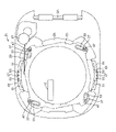
次に、図3および図4を参照して、鍋2と内蓋4とを挟持する挟持機構について説明する。図3は、圧力式炊飯器から外蓋3の上外郭部材3a側の部品を取り外した状態を示す平面図である。図4は、解除位置での、鍋、内蓋、挟持部、および、平行駆動機構を模式的に示す斜視図である。挟持機構は、内蓋4と鍋2とを挟持する挟持部23と、内蓋4と鍋2との挟持が解除されている解除位置から内蓋4と鍋2とが挟持されている挟持位置へ挟持部23を平行移動させる平行駆動機構21とで構成される。
Next, with reference to FIGS. 3 and 4, a holding mechanism for holding the
平行駆動機構21は、制御部14からの指示によって回転制御されるモータ27と、モータ27に巻き付けられるワイヤ29と、モータ27により回転される回転板31とを備える。モータ27は、正回転するとワイヤ29を巻き取り、逆回転するワイヤ29を送り出す。ワイヤ29は、回転板31に連結されている。モータ27が正回転すると、ワイヤ29が巻き取られる分だけ、下外郭部材3b上を回転板31が解除位置から挟持位置へ回転する。また、モータ27が逆回転すると、巻き取られていたワイヤ29が戻されて回転板31が挟持位置から解除位置へ逆回転する。なお、回転板31を逆回転させるのは、回転板31にバネを付けて、回転板31が解除位置から挟持位置に移動する際に生じるバネの反力によってでもよい。
The
回転板31は、円環状の形状を有し、90度ごとに、直線状の4つの溝33が形成されている。回転板31は、例えば、ステンレスなどの金属または樹脂製である。また、挟持部23の上方を覆っている下外郭部材3bにも、外側から内側に向けて直線状の4つの溝37が形成されている。回転板31の溝33および下外郭部材3bの溝37には、挟持部23のピン47が挿入されている。
The rotating
挟持部23は、アーム51により軸53に回動可能に支持されている。また、挟持部23は、アーム51と共に上下移動可能に軸53に支持されている。軸53の上部および下部はホルダ55に連結されている。ホルダ55は、ピン57により外蓋3の上外郭部材3aに固定されている。これにより、挟持部23は、アーム51、ホルダ55、および、ピン57を介して、外蓋3に吊り下げられた構造を有する。各挟持部23のそれぞれのピン47が、回転板31の回転に応じて溝33に沿ってスライドすることで、挟持部23は、鍋2の外方に離れた解除位置から、内方に接近した挟持位置へと平行移動可能になっている。このようにして、回転板31の回転移動を挟持部23の直線移動へと変換することができる。
The sandwiching
挟持部23は、鍋2のフランジ部2bの外方に4つ配置されている。したがって、内蓋4と鍋2とが4カ所で挟持されるので、挟持部23に作用する圧力が分散され、挟持部23を小型化することができる。
Four sandwiching
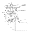
次に図5を参照する。図5は、解除位置での挟持部周囲の部分縦断面斜視図である。鍋2は、有底筒状の鍋本体部2aと、鍋本体部2aの上端から外側方へ延在するフランジ部2bを有する。フランジ部2bは、フランジ部2bの外側端から下方へ延在する延在部2cを有する。鍋2の上部周縁部は、鍋本体部2aの上部、フランジ部2b、および延在部2cにより、逆U字形状を有する。
Next, refer to FIG. FIG. 5 is a partial vertical cross-sectional perspective view around the holding portion at the release position. The
内蓋4は、その外周部に、鍋2のフランジ部2bと対向するフランジ部4aを備えている。フランジ部4aには、内蓋4の外周部に沿って鍋本体部2aの内側を下方に延びるパッキン59が取り付けられている。具体的には、フランジ部4aの外周縁に樹脂部材4bが取り付けられ、フランジ部4aと樹脂部材4bとにパッキン59が挟み込まれている。なお、これに限定されることはなく、フランジ部4aを折り返すことによって、パッキン59を挟み込む構成でもよい。
The
挟持部23は、アーム51と接続され、水平方向に延びる上壁部41と、上壁部41の外側端から下方へ延びる側壁部43と、側壁部43の下端から水平方向内方へ延びる下壁部45と、上壁部41の上面から上方へ突出したピン47とを備える。挟持部23の縦断面は、横U字形状を有する。挟持部23は、金属製であり、例えば、ステンレス製である。
The sandwiching
上壁部41および下壁部45のそれぞれの内側縁は、鍋本体部2aの外周に沿ってカーブ形状を有する。また、下壁部45の上面には、鍋本体部2aの外周に沿って上方に突出する突起部45aが形成されている。
The inner edges of the
次に、挟持機構の動きについて説明する。ユーザが、常圧よりも大きい圧力が鍋2および内蓋4にかかる加圧調理コースを選択すると、制御部14は、モータ27を回転制御する。モータ27が回転すると、平行駆動機構21は、挟持部23を図3から図5に示す解除位置から図6から図8に示す挟持位置へと平行移動させる。
Next, the movement of the pinching mechanism will be described. When the user selects a pressure cooking course in which a pressure higher than the normal pressure is applied to the
図6は、圧力式炊飯器から外蓋の上外郭部材側の部品を取り外し、挟持位置における状態を模式的に示す平面図である。図7は、挟持位置での、鍋、内蓋、挟持部、および、平行駆動機構を模式的に示す斜視図である。図8は、挟持位置で、常圧状態の挟持部周囲の部分縦断面斜視図である。 FIG. 6 is a plan view schematically showing the state in the holding position by removing the parts on the upper outer shell member side of the outer lid from the pressure type rice cooker. FIG. 7 is a perspective view schematically showing the pot, the inner lid, the pinching portion, and the parallel drive mechanism at the pinching position. FIG. 8 is a partial vertical cross-sectional perspective view around the holding portion in a normal pressure state at the holding position.
モータ27の回転駆動により、回転板31が所定角度回転する。回転板31の回転により、各挟持部23のピン47が回転板31の溝33の一端から他端へスライド移動する。このとき、それぞれのピン47は、下外郭部材3bの溝37に沿ってもスライド移動する。このピン47のスライド移動により、アーム51が軸53を中心に内側へ回動し、挟持部23が外側の解除位置から内側の挟持位置へ平行移動する。
The rotary drive of the
また、蓋開放装置8は、モータ27の回転に連動する連動機構を備える。蓋開放装置8は、モータ27の正回転に伴って、炊飯器本体1との係合をロックすることで、開蓋ボタン8Bが押されても外蓋3が開かないようにする。このように、蓋開放装置8は、挟持部23が挟持位置にある間は、外蓋3の開放動作を制限する。
Further, the
挟持位置において、上壁部41は、内蓋4のフランジ部4aの上面と対向し、側壁部43は、内蓋4の外側部および鍋2のフランジ部2bの外側部と対向し、下壁部45は、鍋2のフランジ部2bの下面と対向する。上壁部41の下面から下壁部45の上面までの長さは、内蓋4のフランジ部4aと鍋2のフランジ部2bおよび延在部2cとの厚みよりも長い。したがって、常圧状態では、挟持位置であっても、下壁部45の突起部45aと鍋2の延在部2cの下端との間に隙間がある。また、上壁部41の下面と内蓋4のフランジ部4aの上面との間にも隙間がある。したがって、挟持部23のスライド移動時に、挟持部23は、鍋2および内蓋4と接触しない。
In the pinching position, the
次に図9を参照する。図9は、挟持位置における加圧状態の挟持部周囲の部分縦断面斜視図である。鍋2の温度が上昇し、鍋2内に入れられた水が蒸発して鍋2内の圧力が常圧よりも大きい加圧状態になると、内蓋4が持ち上げられる。内蓋4が持ち上げられると、内蓋4のフランジ部4aの上面と上壁部41の下面とが接触する。さらに、圧力が高くなると、内蓋4のフランジ部4aが挟持部23を押し上げる。挟持部23は、アーム51とともに軸53に沿って上方へ移動する。挟持部23が内蓋4と共に上方へ移動すると、挟持部23の下壁部45の突起部45aが鍋2の延在部2cの下端と接触する。鍋2には、下方へ押し下げる圧力が作用している。したがって、挟持部23の上壁部41には上方へ押し上げる力が作用し、下壁部45には下方へ押し下げる力が作用する。
Next, refer to FIG. FIG. 9 is a partial vertical cross-sectional perspective view around the holding portion in a pressurized state at the holding position. When the temperature of the
加圧状態において、鍋2のフランジ部2bと内蓋4のフランジ部4aとの間に隙間が生じるが、内蓋4のフランジ部4aから垂れ下がるパッキン59が、鍋2内の圧力により、鍋本体部2aの内側面に接触する。これにより、鍋2と内蓋4とが封止され、鍋2内の高圧状態を保つことができる。
In the pressurized state, a gap is created between the
加圧調理が終了すると、圧力弁移動機構12が圧力弁を開放し、鍋2内の圧力が常圧に戻る。圧力弁が開放されると、制御部14がモータ27を回転制御し、モータ27が逆回転する。これにより、回転板31が、逆回転し、それぞれのピン47が他端から一端へスライドする。各ピン47が各溝33に沿ってスライドすることで、各挟持部23が挟持位置から解除位置へ平行移動する。また、モータ27の逆回転に伴って、蓋開放装置8のロックが解除される。これにより、ユーザは、開蓋ボタン8Bを押すことで外蓋3を開けることができる。
When the pressure cooking is completed, the pressure
本実施形態であれば、モータ27の回転に応じて4つの挟持部23を同時に平行移動させることができる。従来のように回転動作により挟持部を駆動する場合、挟持部の移動軌跡が上下方向および水平方向に大きく存在する。本実施形態の場合、挟持部23を水平方向に平行移動した後で加圧時に上下方向に少し移動するので、挟持部23の移動軌跡はほとんど水平方向のみとなり、外蓋3を小型化できる。また、水平方向の平行移動機構である挟持部23をつり下げるように外蓋3に取り付けることで、内蓋4を単純な構造にすることができる。これにより、圧力式炊飯器用の内蓋4の重量を軽くすることができ、内蓋4の洗浄を容易にすることができる。
In the present embodiment, the four sandwiching
また、挟持位置において、常圧時には、上下方向において、鍋2のフランジ部2bの下端と挟持部23との間および内蓋4の外周部であるフランジ部4aの上面と挟持部23との間に隙間を有する。これにより、挟持部23が解除位置から挟持位置に平行移動しても鍋2および内蓋4と接触することがなく、挟持部23に傷が入らない。この結果、挟持部23と鍋2のフランジ部2bの摩耗を防止することができる。
Further, in the pinching position, at normal pressure, in the vertical direction, between the lower end of the
また、挟持位置において、加圧時には、上下方向において、鍋2のフランジ部2bの下端と挟持部23とが接触し、内蓋4の外周部であるフランジ部4aの上面と挟持部23とが接触する。これにより、加圧時において挟持部23により内蓋4と鍋2とを確実に挟持することができる。
Further, in the pinching position, when pressurizing, the lower end of the
また、前記鍋2のフランジ部4aが延在部4cを有することで、フランジ部4aの強度を増すことができ、フランジ部4aの外方向への長さを短くすることができる。これにより、炊飯器本体1の大型化を抑制することができる。
Further, since the
また、挟持部23の下壁部45の上面には、突起部45aが形成されているので、下壁部45の強度を強くすることができる。これにより、挟持部23の下壁部45が、鍋2の延在部2cから押し下げられて変形するのを防止することができる。
Further, since the
本開示は、上記実施形態のものに限らず、次のように変形実施することができる。 The present disclosure is not limited to that of the above embodiment, and can be modified as follows.
(1)上記実施形態において、圧力式炊飯器は、挟持部23を4つ備えていたが、これに限られない。挟持部23を2つ備えてもよいし、1つだけ備えてもよい。
(1) In the above embodiment, the pressure type rice cooker includes four holding
(2)上記実施形態において、鍋2のフランジ部2bは延在部2cを有していたが、これに限られない。フランジ部2bは、例えば、平板状であってもよい。
(2) In the above embodiment, the
(3)上記実施形態において、挟持部23の下壁部45は、突起部45aを有していたが、これに限られない。挟持部23の下壁部45は、例えば、平板状であってもよい。
(3) In the above embodiment, the
(4)上記実施形態において、常圧にて調理する場合は、制御部14はモータ27を回転させないで、挟持部23により鍋2のフランジ部2bと内蓋4の外周部とを挟持させなくてもよい。
(4) In the above embodiment, when cooking at normal pressure, the
本開示にかかる圧力式炊飯器は、例えば、家庭用および業務用に用いられる圧力式炊飯器としても有用である。 The pressure-type rice cooker according to the present disclosure is also useful as, for example, a pressure-type rice cooker used for home and business use.
1 炊飯器本体
1a 鍋収納部
1b 上枠
2 鍋
2a 鍋本体部
2b フランジ部
2c 延在部
3 外蓋
3A ヒンジ軸
3a 上外郭部材
3b 下外郭部材
4 内蓋
4a フランジ部
8 蓋開放装置
8B 開蓋ボタン
9 蒸気筒
9a 蒸気逃がし穴
10 圧力抑制弁
11 安全弁
12 圧力弁移動機構
13 表示操作部
13A 液晶ディスプレイ
13B ボタン
14 制御部
21 平行駆動機構
23 挟持部
27 モータ
29 ワイヤ
31 回転板
33 溝
37 溝
41 上壁部
43 側壁部
45 下壁部
45a 突起部
47 ピン
51 アーム
53 軸
55 ホルダ
57 ピン
59 パッキン
1
Claims (6)
前記鍋の開口を覆う内蓋と、
前記内蓋が着脱可能な外蓋と、
前記内蓋の外周部と前記鍋の前記フランジ部とを挟持する挟持部と、
前記挟持部を解除位置と挟持位置とに往復可能に平行移動させる平行駆動機構とを備え、
前記平行駆動機構は、前記外蓋内に取り付けられ、
前記挟持位置において、常圧時には、上下方向において、前記鍋の前記フランジ部の下端と前記挟持部との間および前記内蓋の外周部の上面と前記挟持部との間に隙間を有し、
前記挟持位置において、加圧時には、上下方向において、前記鍋の前記フランジ部の下端と前記挟持部とが接触し、前記内蓋の外周部の上面と前記挟持部とが接触し、
前記平行駆動機構は、直線状の溝を有する、円環状の形状の回転板と、前記回転板を回転させるモータとを有し、
前記挟持部は、該挟持部の上面から上方に突出したピンを有し、
前記溝に挿入された前記挟持部の前記ピンが、前記回転板の回転に応じて前記溝に沿って移動することにより、前記挟持部は前記解除位置と前記挟持位置とに移動可能である、
圧力式炊飯器。 A pot having a bottomed cylindrical pot body and a flange portion extending outward from the upper end of the pot body,
The inner lid that covers the opening of the pot and
The outer lid to which the inner lid can be attached and detached, and the outer lid
A holding portion that holds the outer peripheral portion of the inner lid and the flange portion of the pot, and a holding portion.
It is equipped with a parallel drive mechanism that reciprocally moves the pinched portion back and forth between the release position and the pinch position.
The parallel drive mechanism is mounted inside the outer lid.
At the pinching position, at normal pressure, there is a gap between the lower end of the flange portion of the pan and the pinching portion and between the upper surface of the outer peripheral portion of the inner lid and the pinching portion in the vertical direction.
At the pinching position, at the time of pressurization, the lower end of the flange portion of the pan and the pinching portion are in contact with each other, and the upper surface of the outer peripheral portion of the inner lid is in contact with the pinching portion.
The parallel drive mechanism has an annular shaped rotary plate having a linear groove and a motor for rotating the rotary plate.
The pinching portion has a pin protruding upward from the upper surface of the pinching portion.
The pin of the pinching portion inserted into the groove moves along the groove in accordance with the rotation of the rotating plate, so that the pinching portion can move between the release position and the pinching position.
Pressure type rice cooker.
前記回転板は、複数個の前記挟持部のそれぞれの前記ピンに対応する複数の前記溝を有し、
複数個の前記挟持部のそれぞれの前記ピンは、前記回転板のそれぞれの前記溝に挿入されている
請求項1に記載の圧力式炊飯器。 A plurality of the holding portions are provided.
The rotating plate has a plurality of the grooves corresponding to the respective pins of the plurality of sandwiches.
The pressure-type rice cooker according to claim 1 , wherein each of the pins of the plurality of holding portions is inserted into the respective grooves of the rotating plate.
請求項1または2に記載の圧力式炊飯器。 The flange portion of the pan has an extending portion extending downward from the outer end.
The pressure-type rice cooker according to claim 1 or 2 .
前記下壁部は、該下壁部の上面から上方に突起する突起部を有し、
加圧時に、前記フランジ部の下端と前記下壁部の前記突起部とが接触する
請求項1から3のいずれか1つに記載の圧力式炊飯器。 The sandwiching portion includes an upper wall portion facing the upper surface of the outer peripheral portion of the inner lid, a side wall portion facing the outer portion of the inner lid and the outer portion of the flange portion of the pot, and the flange portion of the pot. It has a lower wall portion facing the lower surface and has a lower wall portion.
The lower wall portion has a protrusion portion that protrudes upward from the upper surface of the lower wall portion.
The pressure-type rice cooker according to any one of claims 1 to 3 , wherein the lower end of the flange portion and the protrusion of the lower wall portion come into contact with each other during pressurization.
加圧時に、前記パッキンは前記鍋本体部の内側面に接触する、
請求項1から4のいずれか1つに記載の圧力式炊飯器。 A packing that extends downward inside the pot body along the outer peripheral portion of the inner lid is provided.
At the time of pressurization, the packing comes into contact with the inner surface of the pot body.
The pressure-type rice cooker according to any one of claims 1 to 4 .
請求項1から5のいずれか1つに記載の圧力式炊飯器。 A lid opening device for limiting the opening operation of the outer lid is provided while the holding portion is in the holding position.
The pressure-type rice cooker according to any one of claims 1 to 5 .
Priority Applications (2)
| Application Number | Priority Date | Filing Date | Title |
|---|---|---|---|
| JP2017177971A JP7054772B2 (en) | 2017-09-15 | 2017-09-15 | Pressure type rice cooker |
| CN201810933886.3A CN109497827A (en) | 2017-09-15 | 2018-08-16 | Pressure type cooker |
Applications Claiming Priority (1)
| Application Number | Priority Date | Filing Date | Title |
|---|---|---|---|
| JP2017177971A JP7054772B2 (en) | 2017-09-15 | 2017-09-15 | Pressure type rice cooker |
Publications (2)
| Publication Number | Publication Date |
|---|---|
| JP2019051112A JP2019051112A (en) | 2019-04-04 |
| JP7054772B2 true JP7054772B2 (en) | 2022-04-15 |
Family
ID=65745679
Family Applications (1)
| Application Number | Title | Priority Date | Filing Date |
|---|---|---|---|
| JP2017177971A Active JP7054772B2 (en) | 2017-09-15 | 2017-09-15 | Pressure type rice cooker |
Country Status (2)
| Country | Link |
|---|---|
| JP (1) | JP7054772B2 (en) |
| CN (1) | CN109497827A (en) |
Families Citing this family (6)
| Publication number | Priority date | Publication date | Assignee | Title |
|---|---|---|---|---|
| DE202018006410U1 (en) | 2017-08-09 | 2020-04-23 | Sharkninja Operating Llc | Cooking device and components thereof |
| WO2020176477A1 (en) | 2019-02-25 | 2020-09-03 | Sharkninja Operating Llc | Cooking system with guard |
| US11647861B2 (en) | 2020-03-30 | 2023-05-16 | Sharkninja Operating Llc | Cooking device and components thereof |
| JP7281748B2 (en) * | 2020-03-30 | 2023-05-26 | パナソニックIpマネジメント株式会社 | heating cooker |
| KR102475266B1 (en) * | 2021-06-14 | 2022-12-08 | (주)쿠첸 | Cooking apparatus |
| KR102673316B1 (en) | 2022-01-04 | 2024-06-10 | (주)쿠첸 | Cooking apparatus |
Citations (3)
| Publication number | Priority date | Publication date | Assignee | Title |
|---|---|---|---|---|
| JP2008055089A (en) | 2006-09-04 | 2008-03-13 | Mitsubishi Electric Corp | Pressure cooker |
| JP2016174701A (en) | 2015-03-19 | 2016-10-06 | パナソニックIpマネジメント株式会社 | Locking device and container with lid using the same |
| JP6129275B1 (en) | 2015-11-02 | 2017-05-17 | 三菱電機株式会社 | Cooking device |
Family Cites Families (12)
| Publication number | Priority date | Publication date | Assignee | Title |
|---|---|---|---|---|
| JPS58121926A (en) * | 1982-01-14 | 1983-07-20 | 松下電器産業株式会社 | Pressure cooker |
| US5839357A (en) * | 1996-03-15 | 1998-11-24 | Samsung Electronics Co., Ltd. | Electric pressure cooker |
| KR100191803B1 (en) * | 1996-07-05 | 1999-06-15 | 정담 | Electric pressure cooker |
| JP4649424B2 (en) * | 2006-05-17 | 2011-03-09 | パナソニック株式会社 | rice cooker |
| CN200966548Y (en) * | 2006-08-28 | 2007-10-31 | 佛山市顺德区爱德电器有限公司 | Locking structure of the cover of pressure cooker |
| CN202234760U (en) * | 2011-09-29 | 2012-05-30 | 珠海格力电器股份有限公司 | A safety locking device for a pressure cooker and an electric pressure cooker |
| CN202820909U (en) * | 2012-08-31 | 2013-03-27 | 美的集团股份有限公司 | Pressure cooker |
| JP6372777B2 (en) * | 2014-04-16 | 2018-08-15 | パナソニックIpマネジメント株式会社 | Pressure cooker |
| CN204033078U (en) * | 2014-08-05 | 2014-12-24 | 浙江绍兴苏泊尔生活电器有限公司 | Pressure cooker |
| CN204378872U (en) * | 2015-01-26 | 2015-06-10 | 佛山市顺德区美的电热电器制造有限公司 | For cooking apparatus pot cover component and there is its pressure cooker |
| CN205923725U (en) * | 2016-04-15 | 2017-02-08 | 浙江苏泊尔家电制造有限公司 | Pressure cooking appliance |
| CN206284813U (en) * | 2016-10-10 | 2017-06-30 | 佛山市顺德区美的电热电器制造有限公司 | Cooking apparatus |
-
2017
- 2017-09-15 JP JP2017177971A patent/JP7054772B2/en active Active
-
2018
- 2018-08-16 CN CN201810933886.3A patent/CN109497827A/en active Pending
Patent Citations (3)
| Publication number | Priority date | Publication date | Assignee | Title |
|---|---|---|---|---|
| JP2008055089A (en) | 2006-09-04 | 2008-03-13 | Mitsubishi Electric Corp | Pressure cooker |
| JP2016174701A (en) | 2015-03-19 | 2016-10-06 | パナソニックIpマネジメント株式会社 | Locking device and container with lid using the same |
| JP6129275B1 (en) | 2015-11-02 | 2017-05-17 | 三菱電機株式会社 | Cooking device |
Also Published As
| Publication number | Publication date |
|---|---|
| CN109497827A (en) | 2019-03-22 |
| JP2019051112A (en) | 2019-04-04 |
Similar Documents
| Publication | Publication Date | Title |
|---|---|---|
| JP7054772B2 (en) | Pressure type rice cooker | |
| CN105982539B (en) | rice cooker | |
| CN105982531B (en) | Rice cooker | |
| JP6372777B2 (en) | Pressure cooker | |
| JP2007502637A (en) | Pressure cooker with a single control member for decompression and locking / unlocking | |
| CN109310225A (en) | The opening and closing system of the pressure cooker | |
| CN110213984A (en) | Pressure type cooker | |
| JP6861374B2 (en) | Pressure type rice cooker | |
| JP2008048767A (en) | Pressure cooker | |
| JP6945142B2 (en) | Pressure type rice cooker | |
| JP5474157B1 (en) | rice cooker | |
| JP6647002B2 (en) | Cooking pot with lid | |
| CN211093360U (en) | Cooking appliance with holding structure | |
| JP6782459B2 (en) | Pressure type rice cooker | |
| CN107536467B (en) | Electric heating kettle | |
| KR101001203B1 (en) | Rotatable handle | |
| JP2869390B2 (en) | Pressure cooker | |
| KR200235169Y1 (en) | Inner-fan fixing device of electric pressure kettle | |
| CN220089298U (en) | Open-close strainer capable of being used for boiling food | |
| JP5903553B2 (en) | Pressure cooker | |
| KR100689217B1 (en) | Electric pressure cooker | |
| JP7361335B2 (en) | rice cooker | |
| JP2002034782A (en) | Pressure type rice cooker | |
| JP2018126375A (en) | Cooker | |
| JP2007082736A (en) | Cooking device |
Legal Events
| Date | Code | Title | Description |
|---|---|---|---|
| A621 | Written request for application examination |
Free format text: JAPANESE INTERMEDIATE CODE: A621 Effective date: 20200814 |
|
| A977 | Report on retrieval |
Free format text: JAPANESE INTERMEDIATE CODE: A971007 Effective date: 20210720 |
|
| A131 | Notification of reasons for refusal |
Free format text: JAPANESE INTERMEDIATE CODE: A131 Effective date: 20210810 |
|
| A521 | Request for written amendment filed |
Free format text: JAPANESE INTERMEDIATE CODE: A523 Effective date: 20211007 |
|
| TRDD | Decision of grant or rejection written | ||
| A01 | Written decision to grant a patent or to grant a registration (utility model) |
Free format text: JAPANESE INTERMEDIATE CODE: A01 Effective date: 20220208 |
|
| A61 | First payment of annual fees (during grant procedure) |
Free format text: JAPANESE INTERMEDIATE CODE: A61 Effective date: 20220303 |
|
| R151 | Written notification of patent or utility model registration |
Ref document number: 7054772 Country of ref document: JP Free format text: JAPANESE INTERMEDIATE CODE: R151 |