JP6830091B2 - Liquefaction of industrial gas and hydrocarbon gas - Google Patents
Liquefaction of industrial gas and hydrocarbon gas Download PDFInfo
- Publication number
- JP6830091B2 JP6830091B2 JP2018500833A JP2018500833A JP6830091B2 JP 6830091 B2 JP6830091 B2 JP 6830091B2 JP 2018500833 A JP2018500833 A JP 2018500833A JP 2018500833 A JP2018500833 A JP 2018500833A JP 6830091 B2 JP6830091 B2 JP 6830091B2
- Authority
- JP
- Japan
- Prior art keywords
- gas
- vat
- pressure
- gas stream
- ammonium hydroxide
- Prior art date
- Legal status (The legal status is an assumption and is not a legal conclusion. Google has not performed a legal analysis and makes no representation as to the accuracy of the status listed.)
- Active
Links
Images


Classifications
-
- F—MECHANICAL ENGINEERING; LIGHTING; HEATING; WEAPONS; BLASTING
- F25—REFRIGERATION OR COOLING; COMBINED HEATING AND REFRIGERATION SYSTEMS; HEAT PUMP SYSTEMS; MANUFACTURE OR STORAGE OF ICE; LIQUEFACTION SOLIDIFICATION OF GASES
- F25J—LIQUEFACTION, SOLIDIFICATION OR SEPARATION OF GASES OR GASEOUS OR LIQUEFIED GASEOUS MIXTURES BY PRESSURE AND COLD TREATMENT OR BY BRINGING THEM INTO THE SUPERCRITICAL STATE
- F25J1/00—Processes or apparatus for liquefying or solidifying gases or gaseous mixtures
- F25J1/0002—Processes or apparatus for liquefying or solidifying gases or gaseous mixtures characterised by the fluid to be liquefied
- F25J1/0022—Hydrocarbons, e.g. natural gas
-
- F—MECHANICAL ENGINEERING; LIGHTING; HEATING; WEAPONS; BLASTING
- F25—REFRIGERATION OR COOLING; COMBINED HEATING AND REFRIGERATION SYSTEMS; HEAT PUMP SYSTEMS; MANUFACTURE OR STORAGE OF ICE; LIQUEFACTION SOLIDIFICATION OF GASES
- F25B—REFRIGERATION MACHINES, PLANTS OR SYSTEMS; COMBINED HEATING AND REFRIGERATION SYSTEMS; HEAT PUMP SYSTEMS
- F25B15/00—Sorption machines, plants or systems, operating continuously, e.g. absorption type
- F25B15/02—Sorption machines, plants or systems, operating continuously, e.g. absorption type without inert gas
- F25B15/04—Sorption machines, plants or systems, operating continuously, e.g. absorption type without inert gas the refrigerant being ammonia evaporated from aqueous solution
-
- F—MECHANICAL ENGINEERING; LIGHTING; HEATING; WEAPONS; BLASTING
- F25—REFRIGERATION OR COOLING; COMBINED HEATING AND REFRIGERATION SYSTEMS; HEAT PUMP SYSTEMS; MANUFACTURE OR STORAGE OF ICE; LIQUEFACTION SOLIDIFICATION OF GASES
- F25B—REFRIGERATION MACHINES, PLANTS OR SYSTEMS; COMBINED HEATING AND REFRIGERATION SYSTEMS; HEAT PUMP SYSTEMS
- F25B25/00—Machines, plants or systems, using a combination of modes of operation covered by two or more of the groups F25B1/00 - F25B23/00
- F25B25/02—Compression-sorption machines, plants, or systems
-
- F—MECHANICAL ENGINEERING; LIGHTING; HEATING; WEAPONS; BLASTING
- F25—REFRIGERATION OR COOLING; COMBINED HEATING AND REFRIGERATION SYSTEMS; HEAT PUMP SYSTEMS; MANUFACTURE OR STORAGE OF ICE; LIQUEFACTION SOLIDIFICATION OF GASES
- F25J—LIQUEFACTION, SOLIDIFICATION OR SEPARATION OF GASES OR GASEOUS OR LIQUEFIED GASEOUS MIXTURES BY PRESSURE AND COLD TREATMENT OR BY BRINGING THEM INTO THE SUPERCRITICAL STATE
- F25J1/00—Processes or apparatus for liquefying or solidifying gases or gaseous mixtures
- F25J1/0002—Processes or apparatus for liquefying or solidifying gases or gaseous mixtures characterised by the fluid to be liquefied
- F25J1/0005—Light or noble gases
- F25J1/0007—Helium
-
- F—MECHANICAL ENGINEERING; LIGHTING; HEATING; WEAPONS; BLASTING
- F25—REFRIGERATION OR COOLING; COMBINED HEATING AND REFRIGERATION SYSTEMS; HEAT PUMP SYSTEMS; MANUFACTURE OR STORAGE OF ICE; LIQUEFACTION SOLIDIFICATION OF GASES
- F25J—LIQUEFACTION, SOLIDIFICATION OR SEPARATION OF GASES OR GASEOUS OR LIQUEFIED GASEOUS MIXTURES BY PRESSURE AND COLD TREATMENT OR BY BRINGING THEM INTO THE SUPERCRITICAL STATE
- F25J1/00—Processes or apparatus for liquefying or solidifying gases or gaseous mixtures
- F25J1/0002—Processes or apparatus for liquefying or solidifying gases or gaseous mixtures characterised by the fluid to be liquefied
- F25J1/0005—Light or noble gases
- F25J1/001—Hydrogen
-
- F—MECHANICAL ENGINEERING; LIGHTING; HEATING; WEAPONS; BLASTING
- F25—REFRIGERATION OR COOLING; COMBINED HEATING AND REFRIGERATION SYSTEMS; HEAT PUMP SYSTEMS; MANUFACTURE OR STORAGE OF ICE; LIQUEFACTION SOLIDIFICATION OF GASES
- F25J—LIQUEFACTION, SOLIDIFICATION OR SEPARATION OF GASES OR GASEOUS OR LIQUEFIED GASEOUS MIXTURES BY PRESSURE AND COLD TREATMENT OR BY BRINGING THEM INTO THE SUPERCRITICAL STATE
- F25J1/00—Processes or apparatus for liquefying or solidifying gases or gaseous mixtures
- F25J1/0002—Processes or apparatus for liquefying or solidifying gases or gaseous mixtures characterised by the fluid to be liquefied
- F25J1/0012—Primary atmospheric gases, e.g. air
- F25J1/0015—Nitrogen
-
- F—MECHANICAL ENGINEERING; LIGHTING; HEATING; WEAPONS; BLASTING
- F25—REFRIGERATION OR COOLING; COMBINED HEATING AND REFRIGERATION SYSTEMS; HEAT PUMP SYSTEMS; MANUFACTURE OR STORAGE OF ICE; LIQUEFACTION SOLIDIFICATION OF GASES
- F25J—LIQUEFACTION, SOLIDIFICATION OR SEPARATION OF GASES OR GASEOUS OR LIQUEFIED GASEOUS MIXTURES BY PRESSURE AND COLD TREATMENT OR BY BRINGING THEM INTO THE SUPERCRITICAL STATE
- F25J1/00—Processes or apparatus for liquefying or solidifying gases or gaseous mixtures
- F25J1/0002—Processes or apparatus for liquefying or solidifying gases or gaseous mixtures characterised by the fluid to be liquefied
- F25J1/0012—Primary atmospheric gases, e.g. air
- F25J1/0017—Oxygen
-
- F—MECHANICAL ENGINEERING; LIGHTING; HEATING; WEAPONS; BLASTING
- F25—REFRIGERATION OR COOLING; COMBINED HEATING AND REFRIGERATION SYSTEMS; HEAT PUMP SYSTEMS; MANUFACTURE OR STORAGE OF ICE; LIQUEFACTION SOLIDIFICATION OF GASES
- F25J—LIQUEFACTION, SOLIDIFICATION OR SEPARATION OF GASES OR GASEOUS OR LIQUEFIED GASEOUS MIXTURES BY PRESSURE AND COLD TREATMENT OR BY BRINGING THEM INTO THE SUPERCRITICAL STATE
- F25J1/00—Processes or apparatus for liquefying or solidifying gases or gaseous mixtures
- F25J1/0002—Processes or apparatus for liquefying or solidifying gases or gaseous mixtures characterised by the fluid to be liquefied
- F25J1/0012—Primary atmospheric gases, e.g. air
- F25J1/002—Argon
-
- F—MECHANICAL ENGINEERING; LIGHTING; HEATING; WEAPONS; BLASTING
- F25—REFRIGERATION OR COOLING; COMBINED HEATING AND REFRIGERATION SYSTEMS; HEAT PUMP SYSTEMS; MANUFACTURE OR STORAGE OF ICE; LIQUEFACTION SOLIDIFICATION OF GASES
- F25J—LIQUEFACTION, SOLIDIFICATION OR SEPARATION OF GASES OR GASEOUS OR LIQUEFIED GASEOUS MIXTURES BY PRESSURE AND COLD TREATMENT OR BY BRINGING THEM INTO THE SUPERCRITICAL STATE
- F25J1/00—Processes or apparatus for liquefying or solidifying gases or gaseous mixtures
- F25J1/0002—Processes or apparatus for liquefying or solidifying gases or gaseous mixtures characterised by the fluid to be liquefied
- F25J1/0027—Oxides of carbon, e.g. CO2
-
- F—MECHANICAL ENGINEERING; LIGHTING; HEATING; WEAPONS; BLASTING
- F25—REFRIGERATION OR COOLING; COMBINED HEATING AND REFRIGERATION SYSTEMS; HEAT PUMP SYSTEMS; MANUFACTURE OR STORAGE OF ICE; LIQUEFACTION SOLIDIFICATION OF GASES
- F25J—LIQUEFACTION, SOLIDIFICATION OR SEPARATION OF GASES OR GASEOUS OR LIQUEFIED GASEOUS MIXTURES BY PRESSURE AND COLD TREATMENT OR BY BRINGING THEM INTO THE SUPERCRITICAL STATE
- F25J1/00—Processes or apparatus for liquefying or solidifying gases or gaseous mixtures
- F25J1/003—Processes or apparatus for liquefying or solidifying gases or gaseous mixtures characterised by the kind of cold generation within the liquefaction unit for compensating heat leaks and liquid production
- F25J1/0032—Processes or apparatus for liquefying or solidifying gases or gaseous mixtures characterised by the kind of cold generation within the liquefaction unit for compensating heat leaks and liquid production using the feed stream itself or separated fractions from it, i.e. "internal refrigeration"
- F25J1/004—Processes or apparatus for liquefying or solidifying gases or gaseous mixtures characterised by the kind of cold generation within the liquefaction unit for compensating heat leaks and liquid production using the feed stream itself or separated fractions from it, i.e. "internal refrigeration" by flash gas recovery
-
- F—MECHANICAL ENGINEERING; LIGHTING; HEATING; WEAPONS; BLASTING
- F25—REFRIGERATION OR COOLING; COMBINED HEATING AND REFRIGERATION SYSTEMS; HEAT PUMP SYSTEMS; MANUFACTURE OR STORAGE OF ICE; LIQUEFACTION SOLIDIFICATION OF GASES
- F25J—LIQUEFACTION, SOLIDIFICATION OR SEPARATION OF GASES OR GASEOUS OR LIQUEFIED GASEOUS MIXTURES BY PRESSURE AND COLD TREATMENT OR BY BRINGING THEM INTO THE SUPERCRITICAL STATE
- F25J1/00—Processes or apparatus for liquefying or solidifying gases or gaseous mixtures
- F25J1/02—Processes or apparatus for liquefying or solidifying gases or gaseous mixtures requiring the use of refrigeration, e.g. of helium or hydrogen ; Details and kind of the refrigeration system used; Integration with other units or processes; Controlling aspects of the process
- F25J1/0221—Processes or apparatus for liquefying or solidifying gases or gaseous mixtures requiring the use of refrigeration, e.g. of helium or hydrogen ; Details and kind of the refrigeration system used; Integration with other units or processes; Controlling aspects of the process using the cold stored in an external cryogenic component in an open refrigeration loop
-
- F—MECHANICAL ENGINEERING; LIGHTING; HEATING; WEAPONS; BLASTING
- F25—REFRIGERATION OR COOLING; COMBINED HEATING AND REFRIGERATION SYSTEMS; HEAT PUMP SYSTEMS; MANUFACTURE OR STORAGE OF ICE; LIQUEFACTION SOLIDIFICATION OF GASES
- F25J—LIQUEFACTION, SOLIDIFICATION OR SEPARATION OF GASES OR GASEOUS OR LIQUEFIED GASEOUS MIXTURES BY PRESSURE AND COLD TREATMENT OR BY BRINGING THEM INTO THE SUPERCRITICAL STATE
- F25J1/00—Processes or apparatus for liquefying or solidifying gases or gaseous mixtures
- F25J1/02—Processes or apparatus for liquefying or solidifying gases or gaseous mixtures requiring the use of refrigeration, e.g. of helium or hydrogen ; Details and kind of the refrigeration system used; Integration with other units or processes; Controlling aspects of the process
- F25J1/0225—Processes or apparatus for liquefying or solidifying gases or gaseous mixtures requiring the use of refrigeration, e.g. of helium or hydrogen ; Details and kind of the refrigeration system used; Integration with other units or processes; Controlling aspects of the process using other external refrigeration means not provided before, e.g. heat driven absorption chillers
- F25J1/0227—Processes or apparatus for liquefying or solidifying gases or gaseous mixtures requiring the use of refrigeration, e.g. of helium or hydrogen ; Details and kind of the refrigeration system used; Integration with other units or processes; Controlling aspects of the process using other external refrigeration means not provided before, e.g. heat driven absorption chillers within a refrigeration cascade
-
- F—MECHANICAL ENGINEERING; LIGHTING; HEATING; WEAPONS; BLASTING
- F25—REFRIGERATION OR COOLING; COMBINED HEATING AND REFRIGERATION SYSTEMS; HEAT PUMP SYSTEMS; MANUFACTURE OR STORAGE OF ICE; LIQUEFACTION SOLIDIFICATION OF GASES
- F25J—LIQUEFACTION, SOLIDIFICATION OR SEPARATION OF GASES OR GASEOUS OR LIQUEFIED GASEOUS MIXTURES BY PRESSURE AND COLD TREATMENT OR BY BRINGING THEM INTO THE SUPERCRITICAL STATE
- F25J1/00—Processes or apparatus for liquefying or solidifying gases or gaseous mixtures
- F25J1/02—Processes or apparatus for liquefying or solidifying gases or gaseous mixtures requiring the use of refrigeration, e.g. of helium or hydrogen ; Details and kind of the refrigeration system used; Integration with other units or processes; Controlling aspects of the process
- F25J1/0228—Coupling of the liquefaction unit to other units or processes, so-called integrated processes
- F25J1/0235—Heat exchange integration
- F25J1/0236—Heat exchange integration providing refrigeration for different processes treating not the same feed stream
-
- F—MECHANICAL ENGINEERING; LIGHTING; HEATING; WEAPONS; BLASTING
- F25—REFRIGERATION OR COOLING; COMBINED HEATING AND REFRIGERATION SYSTEMS; HEAT PUMP SYSTEMS; MANUFACTURE OR STORAGE OF ICE; LIQUEFACTION SOLIDIFICATION OF GASES
- F25J—LIQUEFACTION, SOLIDIFICATION OR SEPARATION OF GASES OR GASEOUS OR LIQUEFIED GASEOUS MIXTURES BY PRESSURE AND COLD TREATMENT OR BY BRINGING THEM INTO THE SUPERCRITICAL STATE
- F25J1/00—Processes or apparatus for liquefying or solidifying gases or gaseous mixtures
- F25J1/02—Processes or apparatus for liquefying or solidifying gases or gaseous mixtures requiring the use of refrigeration, e.g. of helium or hydrogen ; Details and kind of the refrigeration system used; Integration with other units or processes; Controlling aspects of the process
- F25J1/0228—Coupling of the liquefaction unit to other units or processes, so-called integrated processes
- F25J1/0235—Heat exchange integration
- F25J1/0242—Waste heat recovery, e.g. from heat of compression
-
- F—MECHANICAL ENGINEERING; LIGHTING; HEATING; WEAPONS; BLASTING
- F25—REFRIGERATION OR COOLING; COMBINED HEATING AND REFRIGERATION SYSTEMS; HEAT PUMP SYSTEMS; MANUFACTURE OR STORAGE OF ICE; LIQUEFACTION SOLIDIFICATION OF GASES
- F25B—REFRIGERATION MACHINES, PLANTS OR SYSTEMS; COMBINED HEATING AND REFRIGERATION SYSTEMS; HEAT PUMP SYSTEMS
- F25B9/00—Compression machines, plants or systems, in which the refrigerant is air or other gas of low boiling point
- F25B9/02—Compression machines, plants or systems, in which the refrigerant is air or other gas of low boiling point using Joule-Thompson effect; using vortex effect
-
- F—MECHANICAL ENGINEERING; LIGHTING; HEATING; WEAPONS; BLASTING
- F25—REFRIGERATION OR COOLING; COMBINED HEATING AND REFRIGERATION SYSTEMS; HEAT PUMP SYSTEMS; MANUFACTURE OR STORAGE OF ICE; LIQUEFACTION SOLIDIFICATION OF GASES
- F25J—LIQUEFACTION, SOLIDIFICATION OR SEPARATION OF GASES OR GASEOUS OR LIQUEFIED GASEOUS MIXTURES BY PRESSURE AND COLD TREATMENT OR BY BRINGING THEM INTO THE SUPERCRITICAL STATE
- F25J2205/00—Processes or apparatus using other separation and/or other processing means
- F25J2205/84—Processes or apparatus using other separation and/or other processing means using filter
-
- F—MECHANICAL ENGINEERING; LIGHTING; HEATING; WEAPONS; BLASTING
- F25—REFRIGERATION OR COOLING; COMBINED HEATING AND REFRIGERATION SYSTEMS; HEAT PUMP SYSTEMS; MANUFACTURE OR STORAGE OF ICE; LIQUEFACTION SOLIDIFICATION OF GASES
- F25J—LIQUEFACTION, SOLIDIFICATION OR SEPARATION OF GASES OR GASEOUS OR LIQUEFIED GASEOUS MIXTURES BY PRESSURE AND COLD TREATMENT OR BY BRINGING THEM INTO THE SUPERCRITICAL STATE
- F25J2210/00—Processes characterised by the type or other details of the feed stream
- F25J2210/62—Liquefied natural gas [LNG]; Natural gas liquids [NGL]; Liquefied petroleum gas [LPG]
-
- F—MECHANICAL ENGINEERING; LIGHTING; HEATING; WEAPONS; BLASTING
- F25—REFRIGERATION OR COOLING; COMBINED HEATING AND REFRIGERATION SYSTEMS; HEAT PUMP SYSTEMS; MANUFACTURE OR STORAGE OF ICE; LIQUEFACTION SOLIDIFICATION OF GASES
- F25J—LIQUEFACTION, SOLIDIFICATION OR SEPARATION OF GASES OR GASEOUS OR LIQUEFIED GASEOUS MIXTURES BY PRESSURE AND COLD TREATMENT OR BY BRINGING THEM INTO THE SUPERCRITICAL STATE
- F25J2220/00—Processes or apparatus involving steps for the removal of impurities
- F25J2220/60—Separating impurities from natural gas, e.g. mercury, cyclic hydrocarbons
- F25J2220/68—Separating water or hydrates
-
- F—MECHANICAL ENGINEERING; LIGHTING; HEATING; WEAPONS; BLASTING
- F25—REFRIGERATION OR COOLING; COMBINED HEATING AND REFRIGERATION SYSTEMS; HEAT PUMP SYSTEMS; MANUFACTURE OR STORAGE OF ICE; LIQUEFACTION SOLIDIFICATION OF GASES
- F25J—LIQUEFACTION, SOLIDIFICATION OR SEPARATION OF GASES OR GASEOUS OR LIQUEFIED GASEOUS MIXTURES BY PRESSURE AND COLD TREATMENT OR BY BRINGING THEM INTO THE SUPERCRITICAL STATE
- F25J2230/00—Processes or apparatus involving steps for increasing the pressure of gaseous process streams
- F25J2230/04—Compressor cooling arrangement, e.g. inter- or after-stage cooling or condensate removal
-
- F—MECHANICAL ENGINEERING; LIGHTING; HEATING; WEAPONS; BLASTING
- F25—REFRIGERATION OR COOLING; COMBINED HEATING AND REFRIGERATION SYSTEMS; HEAT PUMP SYSTEMS; MANUFACTURE OR STORAGE OF ICE; LIQUEFACTION SOLIDIFICATION OF GASES
- F25J—LIQUEFACTION, SOLIDIFICATION OR SEPARATION OF GASES OR GASEOUS OR LIQUEFIED GASEOUS MIXTURES BY PRESSURE AND COLD TREATMENT OR BY BRINGING THEM INTO THE SUPERCRITICAL STATE
- F25J2230/00—Processes or apparatus involving steps for increasing the pressure of gaseous process streams
- F25J2230/30—Compression of the feed stream
-
- F—MECHANICAL ENGINEERING; LIGHTING; HEATING; WEAPONS; BLASTING
- F25—REFRIGERATION OR COOLING; COMBINED HEATING AND REFRIGERATION SYSTEMS; HEAT PUMP SYSTEMS; MANUFACTURE OR STORAGE OF ICE; LIQUEFACTION SOLIDIFICATION OF GASES
- F25J—LIQUEFACTION, SOLIDIFICATION OR SEPARATION OF GASES OR GASEOUS OR LIQUEFIED GASEOUS MIXTURES BY PRESSURE AND COLD TREATMENT OR BY BRINGING THEM INTO THE SUPERCRITICAL STATE
- F25J2270/00—Refrigeration techniques used
- F25J2270/90—External refrigeration, e.g. conventional closed-loop mechanical refrigeration unit using Freon or NH3, unspecified external refrigeration
- F25J2270/906—External refrigeration, e.g. conventional closed-loop mechanical refrigeration unit using Freon or NH3, unspecified external refrigeration by heat driven absorption chillers
-
- Y—GENERAL TAGGING OF NEW TECHNOLOGICAL DEVELOPMENTS; GENERAL TAGGING OF CROSS-SECTIONAL TECHNOLOGIES SPANNING OVER SEVERAL SECTIONS OF THE IPC; TECHNICAL SUBJECTS COVERED BY FORMER USPC CROSS-REFERENCE ART COLLECTIONS [XRACs] AND DIGESTS
- Y02—TECHNOLOGIES OR APPLICATIONS FOR MITIGATION OR ADAPTATION AGAINST CLIMATE CHANGE
- Y02A—TECHNOLOGIES FOR ADAPTATION TO CLIMATE CHANGE
- Y02A30/00—Adapting or protecting infrastructure or their operation
- Y02A30/27—Relating to heating, ventilation or air conditioning [HVAC] technologies
-
- Y—GENERAL TAGGING OF NEW TECHNOLOGICAL DEVELOPMENTS; GENERAL TAGGING OF CROSS-SECTIONAL TECHNOLOGIES SPANNING OVER SEVERAL SECTIONS OF THE IPC; TECHNICAL SUBJECTS COVERED BY FORMER USPC CROSS-REFERENCE ART COLLECTIONS [XRACs] AND DIGESTS
- Y02—TECHNOLOGIES OR APPLICATIONS FOR MITIGATION OR ADAPTATION AGAINST CLIMATE CHANGE
- Y02B—CLIMATE CHANGE MITIGATION TECHNOLOGIES RELATED TO BUILDINGS, e.g. HOUSING, HOUSE APPLIANCES OR RELATED END-USER APPLICATIONS
- Y02B30/00—Energy efficient heating, ventilation or air conditioning [HVAC]
- Y02B30/62—Absorption based systems
Landscapes
- Engineering & Computer Science (AREA)
- Physics & Mathematics (AREA)
- Mechanical Engineering (AREA)
- Thermal Sciences (AREA)
- General Engineering & Computer Science (AREA)
- Chemical Kinetics & Catalysis (AREA)
- Chemical & Material Sciences (AREA)
- General Chemical & Material Sciences (AREA)
- Oil, Petroleum & Natural Gas (AREA)
- Health & Medical Sciences (AREA)
- Emergency Medicine (AREA)
- Separation By Low-Temperature Treatments (AREA)
- Sorption Type Refrigeration Machines (AREA)
- Industrial Gases (AREA)
Description
本発明は、工業用ガスもしくは炭化ガスまたはこれらのガス混合物の液化システムおよび方法に関する。 The present invention relates to liquefaction systems and methods for industrial gases or carbonized gases or mixtures thereof.
工業用ガス、例えばCO2、H2S、N2、O2、H2、He、Ar、空気および他のガスならびに炭化水素ガス、例えばメタン、エタン、プロパン、エチレンおよび他の炭化水素ガス、またはこれらガスの混合物は、伝統的に、周知のカルノー冷凍サイクルまたはターボ−エキスパンダ(Turbo-Expander)サイクルに基づく冷凍サイクルを利用して液化される。液化を可能にするこれら工業プロセス中に達成される極低温は、大きな資本を必要とし、大量のエネルギーを必要とし、しかも操業費が多大である複雑なカスケード式冷凍サイクルを必要とする場合がある。 Industrial gases such as CO 2 , H 2 S, N 2 , O 2 , H 2 , He, Ar, air and other gases and hydrocarbon gases such as methane, ethane, propane, ethylene and other hydrocarbon gases, Alternatively, mixtures of these gases are traditionally liquefied using a refrigeration cycle based on the well-known Carnot refrigeration cycle or Turbo-Expander cycle. The cryogenics achieved during these industrial processes that allow liquefaction may require complex cascade refrigeration cycles that require large capital, large amounts of energy, and high operating costs. ..
したがって、当該技術分野において、実施するのに比較的エネルギー効率が良く、経済的であり、しかも実用的であると言える工業用ガスおよび炭化水素ガスまたはこれらのガス混合物を液化する代替方法が要望されている。 Therefore, there is a need for alternative methods of liquefying industrial gases and hydrocarbon gases or mixtures thereof that are relatively energy efficient, economical and practical to implement in the art. ing.
一観点では、本発明は、以下の非順序的ステップを含むガスの液化方法であって、
a.入口圧力を有するガスを受け入れてガスを所望の圧力まで圧縮しまたは減圧するステップと、
b.ガスを少なくとも1つの吸収式冷却機に通して冷却するステップと、
c.ガスの圧力を断熱減少させてガスの少なくとも一部分を液化するステップと、
d.リッチ水酸化アンモニウム流体を精留器内で加熱してトリム熱またはガスがステップ(a)で圧縮された場合にステップ(a)から回収した圧縮熱のうちの一方またはこれらの組み合わせを用いてアンモニアガスを遊離させ、リーン水酸化アンモニウム流体を生じさせるステップと、
e.リーン水酸化アンモニウムを過冷却して蒸気吸収塔の頂部に循環させるステップと、
f.精留器からのアンモニアガスを凝縮して液体アンモニアをほとばしらせて少なくとも1つの吸収式冷却機内での使用のための冷却アンモニアガスを生じさせるステップと、
g.少なくとも1つの吸収式冷却機からのアンモニアガスを蒸気吸収塔内でリーン水酸化アンモニウム中に吸収させてステップ(d)のためのリッチ水酸化アンモニウムを生じさせるステップとを含むことを特徴とする方法を含む。
In one aspect, the present invention is a method of liquefying a gas comprising the following non-sequential steps:
a. The step of accepting gas with inlet pressure and compressing or depressurizing the gas to the desired pressure,
b. The step of cooling the gas through at least one absorption chiller,
c. The step of adiabatically reducing the pressure of the gas to liquefy at least a portion of the gas,
d. Ammonia using one or a combination of the heat of trim or the heat of compression recovered from step (a) when the trim heat or gas is compressed in step (a) by heating the rich ammonium hydroxide fluid in a rectifier. With the step of liberating the gas and producing a lean ammonium hydroxide fluid,
e. The step of supercooling lean ammonium hydroxide and circulating it to the top of the vapor absorption tower,
f. A step of condensing ammonia gas from the rectifier to expel liquid ammonia to produce cooling ammonia gas for use in at least one absorption chiller.
g. A method comprising a step of absorbing ammonia gas from at least one absorption chiller into lean ammonium hydroxide in a vapor absorption tower to produce rich ammonium hydroxide for step (d). including.
ガスは、工業用ガスもしくは炭化水素ガスまたは工業用ガスもしくは炭化水素ガスの任意の混合物を含むのが良い。この方法の結果として、ガスの少なくとも1つの成分、ガスの一部分、またはガスの実質的に全ての液化が得られる。 The gas may include an industrial gas or a hydrocarbon gas or any mixture of an industrial gas or a hydrocarbon gas. The result of this method is the liquefaction of at least one component of the gas, a portion of the gas, or substantially all of the gas.
別の観点では、本発明は、ガス液化システムであって、入口ガスを所望の圧力で受け入れる受け入れ段と、ガスを冷却するための吸収冷凍ループを含む冷却段と、ガスを少なくとも部分的に液化させるためのJT弁を含む液化段とを含むことを特徴とするガス液化システムを含むのが良い。一実施形態では、このシステムは、ガスを所望の圧力まで圧縮する圧縮段と、熱を圧縮段から吸収冷凍ループに伝達する圧縮エネルギー熱回収段とを更に含むのが良い。別の実施形態では、このシステムは、ガスの非液化成分を低圧蒸気再利用ループ内で再利用するガス再利用段を更に含むのが良く、低圧蒸気再利用ループは、圧縮および冷却ガスを更に冷却し、このガスは、次に圧縮段に方向付けられる。 In another aspect, the invention is a gas liquefaction system that liquefies the gas at least partially, with a receiving stage that accepts the inlet gas at a desired pressure, a cooling stage that includes an absorption refrigeration loop to cool the gas. It is preferable to include a gas liquefaction system characterized by including a liquefaction stage including a JT valve for causing. In one embodiment, the system may further include a compression stage that compresses the gas to the desired pressure and a compression energy heat recovery stage that transfers heat from the compression stage to the absorption refrigeration loop. In another embodiment, the system may further include a gas recycling stage that recycles the non-liquefied components of the gas within the low pressure steam recycling loop, the low pressure steam recycling loop further containing compression and cooling gases. After cooling, this gas is then directed to the compression stage.
一実施形態では、吸収冷凍ループは、精留器および蒸気吸収塔を含む。 In one embodiment, the absorption refrigeration loop comprises a rectifier and a vapor absorption tower.
次に、添付の単純化された略図を参照して例示の実施形態により本発明について説明する。 Next, the present invention will be described by way of exemplary embodiments with reference to the accompanying simplified schematic.
物理学において、「ガス」という用語は、物質が理想分子移動度および無限膨張特性を有する物質の状態を含む用語である。本明細書で用いられる「ガス」は、標準温度および標準圧力で気体である物質、例えばCO2、H2S、N2、O2、H2、He、Ar、空気、もしくは炭化水素ガス、例えばメタン、エタン、プロパン、エチレンおよび他の炭化水素ガス、または任意のガス混合物である。本明細書で用いられる「液化ガス」という用語は、販売、処分または商業、研究もしくは工業目的のための使用が可能であるよう液化された任意のガスまたはガス混合物を意味する。
In physics, the term "gas" is a term that includes the state of matter in which the substance has ideal molecular mobility and infinite expansion properties. "Gas", as used herein, is a gas at standard temperature and pressure materials such CO 2, H 2 S, N 2,
本明細書で用いられる「JT弁」または「JT絞り弁」という用語は、ジュール−トムソン効果に従ってガスの断熱膨張を可能にするようになったガス弁を意味する。JT弁は、当該技術分野においては周知であり、市販されている。 As used herein, the term "JT valve" or "JT throttle valve" means a gas valve that has come to allow adiabatic expansion of the gas according to the Joule-Thomson effect. JT valves are well known in the art and are commercially available.
本明細書で用いられる「低圧分離器(low pressure separator)」、すなわち略して“LPS”は、“JT”絞り弁の下流側で指定された低い圧力および低い温度で動作する分離容器を意味し、その結果、液化ガスを流路から取り出すことができまたは流路内で更に処理することができるようになっている。 As used herein, "low pressure separator", or "LPS" for short, means a separator that operates at the specified low pressure and temperature downstream of the "JT" throttle valve. As a result, the liquefied gas can be taken out of the flow path or further processed in the flow path.
本明細書で用いられる「高圧分離器(high pressure separator)」、すなわち略して“HPS”は、ガス冷却のために所望の圧力で動作するとともにJT絞り弁の上流側に配置された分離容器を意味する。 As used herein, a "high pressure separator", or "HPS" for short, operates at the desired pressure for gas cooling and is a separator located upstream of the JT throttle valve. means.
本明細書で用いられる「濃密相」という用語は、これが任意のガスまたはガス混合物に関する場合、ガスのクリコンデンバールよりも高いその圧縮に起因して生じるガスの状態を意味し、クリコンデンバールは、ガスをほぼその臨界温度によって定められた範囲内の温度において温度とは無関係に気相の状態にすることができない下限としての最大温度であり、臨界温度は、物質の気相および液相の示強的性質が互いに等しい圧力と温度の組み合わせである臨界点およびほぼそのクリコンデンサームに対応した温度であり、クリコンデンサームは、天然ガスを圧力とは無関係に液相にすることができない下限としての最大温度である。濃密相では、ガスは、気相の粘性とほぼ同じ粘性を有するが、液相の密度に近い密度を有する場合がある。 As used herein, the term "dense phase", when it comes to any gas or gas mixture, means the state of the gas resulting from its compression higher than the critical point of the gas, which is the critical point. , The critical temperature is the maximum temperature as the lower limit that cannot bring the gas into a gas phase state regardless of the temperature at a temperature within a range determined by its critical temperature, and the critical temperature is the gas phase and liquid phase of the substance. The critical point, which is a combination of pressure and temperature with the same strong properties, and the temperature corresponding to the criconium, which is the lower limit at which natural gas cannot be in the liquid phase regardless of pressure. Is the maximum temperature of. In the dense phase, the gas has a viscosity approximately equal to that of the gas phase, but may have a density close to that of the liquid phase.
本明細書で用いられる「非凝縮性」という用語は、流路内における任意のLPSに関して1つまたは複数の特定の段の動作圧力および温度では液化しないガスを意味している。 As used herein, the term "non-condensable" means a gas that does not liquefy at the operating pressure and temperature of one or more specific stages for any LPS in the flow path.
本明細書で用いられる「吸収冷凍プロセス(absorption refrigeration process)」、すなわち略して“ARP”は、冷凍プロセスを駆動するための熱入力を利用した当該技術分野において購入されている熱力学的冷凍プロセスを利用する冷凍システムを意味している。 As used herein, the "absorption refrigeration process", or "ARP" for short, is a thermodynamic refrigeration process purchased in the art that utilizes the heat input to drive the refrigeration process. It means a refrigeration system that utilizes.
本明細書で用いられる「トリム熱」という用語は、任意の廃熱回収手段、熱伝達媒体、電気抵抗加熱器、または本発明の改造ARPリッチ溶液加熱ループへの熱入力を提供する他の従来手段に由来するシステム中への熱入力を意味している。トリム熱は、好ましくは、低品位熱源から供給される。低品位熱は、エネルギー密度が低く、しかも従来方法によって効率的に変換することができない低温および中程度の温度(中温)熱を意味する。低品位熱の温度範囲について統一された規格は存在しないが、温度が370℃未満の熱源が低品位熱源と見なされ、その理由は、熱が水蒸気ランキンサイクルを用いた温度よりも効果的に低く変換することができないものとみなされているからである。主要な低品位熱源は、太陽熱、地熱および産業廃棄物の熱に由来する。 As used herein, the term "trim heat" refers to any waste heat recovery means, heat transfer medium, electrical resistance heater, or other conventional method that provides heat input to a modified ARP rich solution heating loop of the invention. It means the heat input into the system derived from the means. Trim heat is preferably supplied from a low grade heat source. Low-grade heat means low-temperature and medium-temperature (medium-temperature) heat that has a low energy density and cannot be efficiently converted by conventional methods. There is no uniform standard for the temperature range of low-grade heat, but heat sources with temperatures below 370 ° C are considered low-grade heat sources because the heat is effectively lower than the temperature using the steam Rankine cycle. This is because it is considered unconvertible. The main low-grade heat sources come from solar heat, geothermal heat and the heat of industrial waste.
本明細書で用いられる「機械的冷凍プロセス」という用語は、冷凍プロセスを駆動するための圧縮入力を利用した当該技術分野において公認されている熱力学的冷凍プロセスを利用した冷凍システムを意味する。 As used herein, the term "mechanical refrigeration process" means a refrigeration system utilizing a thermodynamic refrigeration process recognized in the art that utilizes a compression input to drive the refrigeration process.
本明細書で用いられる「ターボ−エキスパンダ冷凍プロセス」という用語は、断熱膨張および冷凍プロセスとしての圧縮のための仕事の回収を利用する当該技術分野において公認されている熱力学的冷凍プロセスを利用した冷凍システムを意味している。 As used herein, the term "turbo-expander freezing process" utilizes a thermodynamic freezing process recognized in the art that utilizes the recovery of work for adiabatic expansion and compression as a freezing process. It means a freezing system.
一観点では、本発明の実施形態は、ガス受け入れ段、冷却段、1つまたは複数の液化段、および冷却段を駆動する改造型ARPを含むシステムである。好ましい実施形態では、本発明はまた、圧縮段、1つまたは2つ以上の圧縮エネルギー回収段の熱およびガス再利用段を更に含む場合がある。本発明の一実施形態は、入口ガス流の潜在的エネルギー(エンタルピー)を利用するとともにガス液化プロセスの全体的熱力学的効率を向上させるよう液化プロセスの圧縮段中の圧縮エネルギー熱を回収しようとするものである。 In one aspect, embodiments of the present invention are systems that include a gas receiving stage, a cooling stage, one or more liquefaction stages, and a modified ARP that drives the cooling stages. In a preferred embodiment, the invention may also further include a heat and gas recycling stage of a compression stage, one or more compression energy recovery stages. One embodiment of the present invention attempts to recover the compressed energy heat in the compression stage of the liquefaction process so as to utilize the potential energy (enthalpy) of the inlet gas stream and improve the overall thermodynamic efficiency of the gas liquefaction process. Is what you do.
一実施形態では、図1に概略的に示されているように、本発明は、改造型水酸化アンモニウム吸収冷凍システムと組み合わされたガス液化システムである。液化されるべきガスまたはガス混合物に対する圧縮仕事の結果として生じた圧縮エネルギー熱は、水酸化アンモニウムを利用して熱交換によって作業流体ガス流から熱を吸収することによって回収できる。従来型ガス処理技術は、この大量の低品位熱エネルギーを空気フィン型ファンか水冷システム化のいずれかにより周囲環境に放出する。本発明の実施形態は、冷凍冷却作用をもたらしてガスの液化を可能にする吸収冷凍サイクルで回収された圧縮エネルギー熱を利用する。 In one embodiment, as schematically shown in FIG. 1, the present invention is a gas liquefaction system combined with a modified ammonium hydroxide absorption refrigeration system. The compression energy heat generated as a result of the compression work on the gas or gas mixture to be liquefied can be recovered by absorbing heat from the working fluid gas stream by heat exchange utilizing ammonium hydroxide. Conventional gas treatment technology releases this large amount of low-grade thermal energy to the surrounding environment either through an air fin fan or a water cooling system. Embodiments of the present invention utilize compressed energy heat recovered in an absorption refrigeration cycle that provides refrigeration cooling and allows gas liquefaction.
液化されるべきガスで利用できる潜在的エネルギー(エンタルピー)は、ガスがシステムに入っているときにガスの圧力および温度に直接関連づけられ、そして圧力減少冷凍プロセス、例えばジュール−トムソン(JT)圧力減少プロセス中に利用されて断熱圧力減少からの自動冷凍によってガスまたはガス混合物を冷却する。JTプロセスは、堅固であって単純でありしかも気−液相エンベロープ内での動作に対して実用上の制限を加えない状態での冷凍に適しており、かかるJTプロセスは、複雑であって費用が高くつき、しかも気−液相エンベロープの外側での動作を必要とする実用上の制限を有する特殊型極低温回転機器の使用を必要としない。 The potential energy (enthalpy) available in the gas to be liquefied is directly related to the pressure and temperature of the gas as it enters the system, and pressure reduction refrigeration processes such as Joule-Thomson (JT) pressure reduction. Utilized during the process to cool the gas or gas mixture by automatic freezing from adiabatic pressure reduction. The JT process is robust, simple, and suitable for freezing without practical restrictions on its operation within the gas-liquid phase envelope, which is complex and costly. Does not require the use of special cryogenic rotating equipment, which is expensive and has practical limitations that require operation outside the gas-liquid phase envelope.
熱源により、吸収冷凍システムは、代表的には、吸収冷凍システムによって生じる冷却エネルギーと比較して、5%未満の正味電気エネルギーを利用する。液化中のガス流に与えられる圧縮仕事から回収される低品位圧縮エネルギー熱は、特定のガス液化用途および液化のために採用される方法に応じて、幾分かの、全ての、または過剰の冷凍デューティを提供することができる。不十分な熱エネルギーが液化サイクルから回収されるのに役立つ用途では、他の利用可能な低品位廃熱流および/または他の従来型熱入力手段の形態をした追加のトリム熱エネルギーが必要とされる冷凍デューティを吸収冷凍システムによって生じさせることができるようにするのに必要な熱エネルギーを提供するために必要とされる場合がある。 Due to the heat source, the absorption refrigeration system typically utilizes less than 5% net electrical energy compared to the cooling energy produced by the absorption refrigeration system. The low-grade compression energy heat recovered from the compression work applied to the gas stream during liquefaction is some, all, or excess, depending on the particular gas liquefaction application and the method adopted for the liquefaction. Refrigeration duty can be provided. Applications that help recover insufficient thermal energy from the liquefaction cycle require additional trim thermal energy in the form of other available low grade waste heat streams and / or other conventional heat input means. It may be required to provide the thermal energy required to allow the refrigeration duty to be generated by the absorption refrigeration system.
吸収冷凍システムは、リッチ水酸化アンモニウム溶液からアンモニアを遊離させるために熱エネルギーを用いる精留器または精留塔および一実施形態では冷凍機またはチラーが10kPa動作圧力において−71℃という低い温度で動作することができるようにする蒸気吸収塔(VAT)を含む。VAT設計は、従来型機械式真空ポンプが所望の真空動作圧力を達成するための必要性をなくすよう熱力学的原理を採用している。VAT設計はまた、無水蒸気アンモニアがVATの頂部でおよびオプションとしてVATの追加の入口箇所でリーン水酸化アンモニウム溶液中に吸収するときの溶解熱および凝縮エネルギー熱のうちの少なくとも何割かまたは場合によっては全ての回収を可能にする。水頭が水酸化アンモニウム溶液を過冷却状態に維持している状態で溶液強度および温度は、VAT内で頂部から底部に向かって増大し、ついには、最終のリッチ溶液強度に達するようになる。溶解熱および凝縮熱は、リッチ溶液内で有用なエネルギーとして維持され、このことは、このエネルギーをヒートシンクに捨てる従来型吸収器とは異なる。 The absorption refrigeration system is a rectifier or rectifier that uses thermal energy to liberate ammonia from the rich ammonium hydroxide solution and, in one embodiment, the chiller or chiller operating at a low temperature of -71 ° C. at an operating pressure of 10 kPa. Includes a vapor absorption tower (VAT) that allows it to be. The VAT design employs thermodynamic principles to eliminate the need for conventional mechanical vacuum pumps to achieve the desired vacuum operating pressure. The VAT design also includes at least some percentage of the heat of solution and heat of condensation energy as vapor-free ammonia absorbs into a lean ammonium hydroxide solution at the top of the VAT and optionally at an additional inlet of the VAT, or in some cases. Allows all recovery. With the head keeping the ammonium hydroxide solution supercooled, the solution strength and temperature increase from top to bottom in the VAT until the final rich solution strength is reached. The heat of solution and heat of condensation are maintained as useful energy in the rich solution, which is different from conventional absorbers that dispose of this energy in the heat sink.
受け入れ段では、入口ガス流は、所望の圧力まで圧縮されまたは減圧され、この所望の圧力は、冷却/液化プロセスの開始に先立ってガスの臨界圧力を上回る場合がありまたは下回る場合がある。入口ガス流が所望の圧力を上回る場合、この入口ガス流は、JT弁で絞られてプロセスを低温で開始させることができる。かかる場合、改造型ARPに伝わるよう回収される圧縮熱はゼロである。 At the receiving stage, the inlet gas stream is compressed or depressurized to the desired pressure, which may or may not exceed the critical pressure of the gas prior to the start of the cooling / liquefaction process. If the inlet gas flow exceeds the desired pressure, this inlet gas flow can be throttled with a JT valve to start the process at low temperature. In such a case, the heat of compression recovered so as to be transmitted to the modified ARP is zero.
一実施形態では、ガスに関する臨界点を下回る入口圧力を有するガスを液化する方法が提供される。この方法は、圧縮機(1つまたは2つ以上の段)、圧縮エネルギー熱の熱的回収システム、改造型ARP、1つまたは2つ以上のJT弁、1つまたは2つ以上のLPS容器、および1つまたは2つ以上の段を備えた再利用ガス冷凍圧縮機を利用する。このガス液化方法は、従来型機械式冷凍システム、例えばカルノーサイクルを利用する第2の組をなす冷凍圧縮機の必要性を減少させまたはなくす。液化中のガスは、JTフラッシュの結果としての蒸気相成分が再利用されて液相成分が貯蔵部に送られているときに熱伝達流体としての役目を果たす。この方法のかかる実施例は、CO2、H2S、プロパンの液化、または軽度の留分C3+天然ガス液(NGL)回収に適している場合があり、この場合、液化に必要な温度は、−70℃よりも温かい。 In one embodiment, a method of liquefying a gas having an inlet pressure below a critical point for the gas is provided. This method includes a compressor (one or more stages), a thermal recovery system for compression energy heat, a modified ARP, one or more JT valves, one or more LPS vessels, And utilize a recycled gas refrigerating compressor with one or more stages. This gas liquefaction method reduces or eliminates the need for conventional mechanical refrigeration systems, such as a second set of refrigeration compressors utilizing the Carnot cycle. The gas being liquefied serves as a heat transfer fluid when the vapor phase components resulting from the JT flush are reused and the liquid phase components are sent to the reservoir. Such embodiments of the method, CO 2, H 2 S, may be suitable for liquefaction of propane, or mild fraction C 3 + natural gas liquids (NGL) recovery, in this case, the temperature required to liquefy Is warmer than -70 ° C.
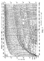
例えば、この方法は、図2にPFDとして概略的に示され、図3ではモリエ線図として概略的に示されたCO2ガスを液化するために使用されるのが良い。代表的な液体CO2貯蔵範囲は、−15℃〜−29℃である。このプロセスは、約1600kPaの圧力において約−23℃の温度で液体CO2を生じさせることができる。入口では、CO2は、大気圧でしかもガスの臨界点よりも十分に低い約30℃で送り出される。次に、このガスは、熱交換器を通過しながら段階的に圧縮され、これら熱交換器は、リッチ水酸化アンモニウム溶液との直接的な連絡関係をなす熱交換器によって圧縮エネルギー熱を回収し、それにより改造型吸収冷凍冷却システムに動力供給するのに必要な熱エネルギーの全てまたは一部分を提供する。次に、圧縮CO2は、少なくとも1つの吸収式チラーによって冷却される。吸収式チラーシステムに動力供給するための熱エネルギーは、回収された圧縮エネルギー熱および/またはトリム熱の任意の組み合わせによって提供され、このトリム熱は、直接もしくは間接的燃焼熱交換器または必要な温度または質量流量条件を備えた他の利用可能な廃熱回収流によって作られるのが良い。 For example, this method is preferably used to liquefy the CO 2 gas schematically shown as PFD in FIG. 2 and generally shown as a Morie diagram in FIG. A typical liquid CO 2 storage range is −15 ° C. to −29 ° C. This process can produce liquid CO 2 at a temperature of about -23 ° C. at a pressure of about 1600 kPa. At the inlet, CO 2 is delivered at about 30 ° C. at atmospheric pressure and well below the critical point of the gas. The gas is then gradually compressed as it passes through the heat exchangers, which recover the compressed energy heat by the heat exchangers in direct communication with the rich ammonium hydroxide solution. It provides all or part of the thermal energy required to power the modified absorption refrigeration and cooling system. The compressed CO 2 is then cooled by at least one absorption chiller. The thermal energy to power the absorption chiller system is provided by any combination of recovered compression energy heat and / or trim heat, which is the direct or indirect combustion heat exchanger or the required temperature. Alternatively, it may be made by another available waste heat recovery stream with mass flow conditions.
次に、圧縮されかつ冷却されたCO2は、放出圧力および放出温度でJT弁を通って低圧分離器(LPS)中に放出され、したがって、CO2は、幾つかの条件下においては過冷却状態である場合のある2段階気−液状態にある。液体CO2は、任意のフラッシュガスおよび/または非凝縮性蒸気を含むガス部分が再利用圧縮機、ガス抜きのためのブリード流、燃料ガスおよび/または場合によっては追加の処理に差し向けられている間、貯蔵容器に放出されるのが良い。再利用圧縮機は、ガス部分が図2においてCO2−11およびCO2−11aで示されている圧縮段でガス流路中に導入される再利用ループの一部である。 The compressed and cooled CO 2 is then released into the low pressure separator (LPS) through the JT valve at the release pressure and temperature, thus the CO 2 is supercooled under some conditions. It is in a two-stage gas-liquid state, which may be a state. Liquid CO 2 has a gas portion containing any flash gas and / or non-condensable vapor directed to a reusable compressor, bleed stream for degassing, fuel gas and / or optionally additional treatment. It should be released into a storage container while Recycling compressor is part of the recycling loop gas portion is introduced into the gas flow path in the compression stage shown in CO 2 -11 and CO 2 -11A in Figure 2.
別の実施形態では、本発明は、臨界点を上回った状態で受け入れられまたは圧縮機(1つまたは2つ以上の段)、圧縮エネルギー熱の熱的回収システム、改造型ARP、1つまたは2つ以上のJT弁、1つまたは2つ以上のLPS容器、および1つまたは2つ以上の段を備えた再利用ガス冷凍圧縮機を利用して臨界点を上回った状態まで圧縮されたガスを液化する方法を提供する。この方法は、圧縮エネルギー熱の熱的回収システムと吸収式冷凍システムと1つまたは2つ以上のLPS、1つまたは2つ以上のJT弁、および1つまたは2つ以上の圧縮段を備えた再利用ガス冷凍圧縮機からの低圧再利用ガス蒸気流を有する熱交換器の任意の組み合わせにより濃密相ガスを冷却することによって液化を可能にするのに十分に濃密相にする圧力までのガスの圧縮を利用する冷凍サイクル(これには限定されない)を含む流路を利用する。液化プロセスに入るガスの供給圧力および温度に応じて、液化されるべき特定のガスまたはガス混合物の冷却プロセス中に奪われる熱(エンタルピー変化)を最適化するのに十分臨界圧力および臨界温度を上回る濃密相に更に圧縮することが有利な場合がある。 In another embodiment, the invention is accepted above a critical point or compressor (one or more stages), a thermal recovery system for compression energy heat, a modified ARP, one or two. Gas compressed to above the critical point using a recycled gas refrigeration compressor with one or more JT valves, one or more LPS containers, and one or more stages. Provide a method of liquefaction. This method comprises a thermal recovery system for compressed energy heat, an absorption refrigeration system, one or more LPSs, one or more JT valves, and one or more compression stages. Low-pressure recycled gas from a recycled gas refrigerating compressor of gas up to a pressure that makes it dense enough to allow liquefaction by cooling the dense phase gas by any combination of heat exchangers with steam flow. Utilize a flow path that includes a refrigeration cycle that utilizes compression, but is not limited to this. Sufficiently above the critical pressure and temperature to optimize the heat (enthalpy change) taken during the cooling process of a particular gas or gas mixture to be liquefied, depending on the supply pressure and temperature of the gas entering the liquefaction process. Further compression into a dense phase may be advantageous.
特定のガスまたはガス混合物の冷却プロセスのために選択された圧力は、圧力と比エンタルピーの関係を表わすモリエ線図上に提供されているように臨界点よりも上方のガスおよびガス混合物のための等温線の勾配変化に直接関連づけられる。等温線の勾配が垂直である(無限勾配)点は、相当な熱伝達が所与の温度でガスまたはガス混合物が所与の場合に起こるための最大の潜在的可能性を提供する。選択された実際の圧力は、必ずしも、この点である必要はなく、というのは、要因の組み合わせ、例えば圧縮および熱交換機器に関する実用的な圧力および温度限度ならびに吸収式冷却システムによって利用できまたは提供される最小温度が考慮されるために必要だからである。特定のガスに関する等温線の勾配は、液化ステップに先立って所与のガスまたはガス混合物の冷却のための最適圧力の選択を助けるようモリエ線図(X軸が比エンタルピー、Y軸が絶対圧力)上で観察できる。以下において、この選択プロセスについて更に説明する。 The pressure selected for the cooling process of a particular gas or gas mixture is for the gas and gas mixture above the critical point as provided on the Molie diagram, which represents the relationship between pressure and specific enthalpy. It is directly related to the gradient change of the isotherm. The point where the isotherm slope is vertical (infinite slope) offers the greatest potential for considerable heat transfer to occur at a given temperature with a given gas or gas mixture. The actual pressure selected does not necessarily have to be at this point, because it is available or provided by a combination of factors, such as practical pressure and temperature limits for compression and heat exchange equipment and absorption cooling systems. This is because it is necessary for the minimum temperature to be taken into consideration. The isotherm gradient for a particular gas is a Molie diagram (specific enthalpy on the X-axis, absolute pressure on the Y-axis) to help select the optimum pressure for cooling a given gas or gas mixture prior to the liquefaction step. Can be observed above. The selection process will be further described below.
この実施形態の実施例では、ガスは、所望の濃密相圧力において入口圧力で受け入れられ、または入口圧力が所望の濃密相圧力の状態にはない場合、液化に必要な所望の濃密相圧力までガスを圧縮しまたは減圧する。圧縮された場合、圧縮エネルギー熱を熱交換器によって回収してリッチ水酸化アンモニウム溶液に伝達して改造型吸収冷凍チラーシステムに動力供給するのに必要な熱エネルギーの全てまたは一部分を提供するのが良い。圧縮熱から回収された熱エネルギーが不十分である場合、トリム熱を直接または間接燃焼熱交換または必要な温度および質量流量条件を備えた他の利用可能な廃熱回収流によって提供するのが良い。 In an embodiment of this embodiment, the gas is accepted at the inlet pressure at the desired dense phase pressure, or if the inlet pressure is not in the desired dense phase pressure state, the gas is up to the desired dense phase pressure required for liquefaction. Compress or depressurize. When compressed, it provides all or part of the thermal energy required to recover the compressed energy heat with a heat exchanger and transfer it to a rich ammonium hydroxide solution to power the modified absorption chiller system. good. If the thermal energy recovered from the heat of compression is insufficient, it is better to provide the trim heat by direct or indirect combustion heat exchange or other available waste heat recovery stream with the required temperature and mass flow conditions. ..
入口ガスは、JT弁の入口圧力に等しい所望の最終圧力に達するのに必要な単一または多段圧縮機で圧縮されるのが良い。一般的に言って、一実施形態では、任意特定の圧縮段のための放出温度は、特定の圧縮機器の仕様に応じて約150〜160℃に制限される。 The inlet gas may be compressed with a single or multi-stage compressor required to reach the desired final pressure equal to the inlet pressure of the JT valve. Generally speaking, in one embodiment, the emission temperature for any particular compression stage is limited to about 150-160 ° C. depending on the specifications of the particular compression equipment.
圧縮ガスは、少なくとも1段、好ましくは2、3、または4段の吸収式チラーによって−70℃の最低温度まで冷却される。一実施形態では、圧縮ガスは、当初、以下に説明するようにLPSからの低圧蒸気再利用流で冷却されるのが良い。 The compressed gas is cooled to a minimum temperature of −70 ° C. by an absorption chiller of at least one stage, preferably two, three, or four stages. In one embodiment, the compressed gas is initially preferably cooled by a low pressure vapor reusing stream from the LPS, as described below.
冷却された工業用ガスまたはガス混合物は、JT弁を通って放出圧力および放出温度で低圧分離器(LPS)中に放出され、その結果、ガスは、このガスのための2段領域内で蒸気品位“X”にあるようになる。図6Aおよび図6Bでは、それぞれ、M17およびM12ではX=0.53である。液体は、LPSから貯蔵容器に放出され、そして蒸気は、低圧蒸気再利用流に差し向けられる。この再利用流には、吸収式チラー内での濃密相ガスの冷却に先立って、当初濃密工業用ガスまたはガス混合物を所望の温度まで冷却する熱交換器が組み込まれている。低圧蒸気再利用流は、それにより、圧縮機器の入口に適した温度まで温められ、次に、1つまたは2つ以上の段で圧縮され、ついには、所望の濃密相液化圧力に達し、次に、この蒸気再利用流を入口ガス流と合流される。 The cooled industrial gas or gas mixture is released through a JT valve into a low pressure separator (LPS) at discharge pressure and temperature, so that the gas steams within a two-stage region for this gas. It comes to be in the grade "X". In FIGS. 6A and 6B, X = 0.53 for M17 and M12, respectively. The liquid is discharged from the LPS into the storage vessel and the vapor is directed to a low pressure vapor recycling stream. This recycle stream incorporates a heat exchanger that initially cools the dense industrial gas or gas mixture to the desired temperature prior to cooling the dense phase gas in the absorption chiller. The low-pressure steam recycle stream is thereby warmed to a temperature suitable for the inlet of the compression equipment, then compressed in one or more stages, finally reaching the desired dense phase liquefaction pressure, and then In addition, this steam reuse flow is merged with the inlet gas flow.
LPSからの非凝縮性蒸気は、特定の工業用ガスまたはガス混合物の特性およびプロセス用途に応じて、ガス抜き、追加の処理のためのブリード流または燃料ガスとして差し向けられるのが良い。 The non-condensable vapor from the LPS may be directed as a bleed stream or fuel gas for degassing, additional processing, depending on the properties of the particular industrial gas or gas mixture and process application.
LPSから取り出された液体をほとばしらせる(フラッシングする)追加の段を実施して所望ならば追加のJT弁、LPS容器、および所望ならば圧縮段の使用によって液化工業ガスまたはガス混合物の温度および圧力を更に減少させるのが良い。 The temperature of the liquefied industrial gas or gas mixture and the temperature of the liquefied industrial gas or gas mixture by the use of an additional JT valve, LPS vessel, and if desired a compression stage, with an additional stage of flushing the liquid removed from the LPS. It is better to reduce the pressure further.
何種類かのガスに関し、吸収式冷凍チラーは、所望の最終液化温度での過冷却状態への冷却濃密相流体の単純なJTフラッシングを可能にするのに十分に低い温度では動作しないが、このガスに関する気−液相エンベロープ内のある特定の蒸気品位“X”に合った所望の最終温度および圧力へのフラッシングを可能にする。液体部分は、LPSから取り出されて液体貯蔵容器に送られ、他方、気相は、分離器から除去され、そして、低温低圧気相を用いて再集団吸収式チラー型熱交換器内で冷却された温かい濃密相ガス流を更に冷却するのが良い。 For some gases, absorption refrigeration chillers do not operate at temperatures low enough to allow simple JT flushing of the cooled dense phase fluid to a supercooled state at the desired final liquefaction temperature, but this Allows flushing to the desired final temperature and pressure for a particular vapor grade "X" within the gas-liquid phase envelope with respect to the gas. The liquid portion is removed from the LPS and sent to the liquid storage vessel, while the gas phase is removed from the separator and cooled in a regroup absorption chiller heat exchanger using the low temperature low pressure gas phase. It is better to further cool the warm dense phase gas stream.
一実施形態では、濃密相ガス流を冷却することによって、LPSからの低圧蒸気再利用流は、最終の吸収式チラー動作温度とほぼ同じ温度まで温められる。次に、この低圧蒸気再利用流は、別の熱交換器に差し向けられるのが良く、この別の熱交換器は、圧縮機ループ内の再利用ガスを選択された再利用圧縮機設備に許容可能な温度まで更に温める(標準ノジュラー鉄または炭素鋼材料を利用するとともに極低温動作にとって必要なステンレス鋼の必要性を回避するよう−29℃以上の温度)。低圧蒸気再利用ガスが十分なエネルギーをいったん交換して適切に温められると、この最良ガスを入口ガス流と合流させて本明細書に説明するように圧縮するのが良い。 In one embodiment, by cooling the dense phase gas stream, the low pressure vapor reuse stream from the LPS is warmed to about the same temperature as the final absorption chiller operating temperature. This low pressure steam recycle stream can then be directed to another heat exchanger, which recycles the gas in the compressor loop to the selected recycle compressor facility. Further warm to an acceptable temperature (temperature above -29 ° C to utilize standard nodular iron or carbon steel materials and avoid the need for stainless steel required for cryogenic operation). Once the low pressure steam recycled gas has exchanged sufficient energy and is properly warmed, it is better to combine this best gas with the inlet gas stream and compress it as described herein.
特定用途に応じて他のプロセスに利用できる過剰冷却方式が存在する場合がありまたは十分な冷却デューティを吸収式冷凍冷却機器によって生じさせることができるのに必要な追加のトリム熱エネルギーが存在する場合がある。圧縮エネルギー熱が入口流および再利用流から回収された後(合流した流れは、入口流+再利用流(“Y”)に等しい)、この流れを吸収式冷却システムの1つまたは2つ以上の段によって更に冷却し、ついには、吸収式冷却システムからの所望の最終温度に達するようにする。LPSからの低圧蒸気再利用流は、液化されるべき入口流量の“Y”または“X/(1−X)”倍に等しい質量流量を有する。LPSを出た液体質量流量は、システムに入ったガスまたはガス混合物の入口質量流量から所望のシステム液化条件での非凝縮性ガスの蓄積を阻止するために任意の燃料ガスまたはブリード流を引いた量に等しい。 There may be overcooling schemes available for other processes depending on the particular application, or if there is additional trim thermal energy required to allow sufficient cooling duty to be generated by the absorption refrigeration equipment. There is. After the compressed energy heat has been recovered from the inlet and reuse streams (the merged stream is equal to the inlet stream + reuse stream (“Y”)), this flow is combined into one or more of the absorption cooling systems. Further cooling is achieved by the steps of the absorption cooling system to reach the desired final temperature. The low pressure vapor reuse stream from the LPS has a mass flow rate equal to "Y" or "X / (1-X)" times the inlet flow rate to be liquefied. The liquid mass flow rate exiting the LPS subtracted any fuel gas or bleed flow from the inlet mass flow rate of the gas or gas mixture that entered the system to prevent the accumulation of non-condensable gas under the desired system liquefaction conditions. Equal to the quantity.
本明細書において説明するガス液化方法は、現在大規模LNG液化施設で利用されていて建造するのに相当大きな正味のエネルギー入力および資本を必要するとともに操業したり維持したりするのに相当大きな運転資本を必要とするカスケード式多段外部冷凍プロセスまたは混合冷媒システムによる従来型の冷凍プロセスによって必要とされる追加の機器の必要性を最小限に抑えることができる。加うるに、ロウ付けアルミニウム熱交換器(BAHX)および極低温回転機器は不要である。 The gas liquefaction methods described herein are currently used in large-scale LNG liquefaction facilities and require significant net energy input and capital to build, as well as significant operation to operate and maintain. The need for additional equipment required by a capital-intensive cascade multi-stage external refrigeration process or a conventional refrigeration process with a mixed refrigerant system can be minimized. In addition, a brazed aluminum heat exchanger (BAHX) and cryogenic rotating equipment are not required.
結果的に再利用またはガスブリード流が追加される低温かつ低圧液化ガスまたは混合ガス生成物が望まれる場合に追加のJTフラッシュ段を追加するのが良い。液化中のガスまたはガス混合物の特性に応じて、燃料ガスのための蒸気流のうちの1つまたは組み合わせを持ちまたはこれを非凝縮性ガスまたはガス混合物の液化を可能にする別の動作圧力および温度での別の液化プロセスにおける非凝縮性ガスの回収のための供給流として用いることが望ましい場合がある。この方法の一例は、−170℃という低い液化温度での用途に適しており、そしてLNG生産または重度のC2+回収に特に適している。 An additional JT flash stage may be added if a low temperature and low pressure liquefied gas or mixed gas product is desired that results in the addition of reuse or gas bleed flow. Depending on the properties of the gas or gas mixture being liquefied, it has one or a combination of vapor streams for the fuel gas or another operating pressure that allows this to liquefy the non-condensable gas or gas mixture and It may be desirable to use it as a feed stream for the recovery of non-condensable gas in another liquefaction process at temperature. An example of this method is suitable for applications at lower liquefaction temperature of -170 ° C., and is particularly suitable for LNG production or severe C 2 + recovery.
濃密相ガスを用いる上述の方法は、断熱膨張に先立って、メタンを液化するのに十分な−71℃の温度までガスを冷却することができる。別の実施形態では、必要な液化温度が低い場合、本発明は、追加の冷却ステップを含むのが良く、この追加の冷却ステップでは、別個の液化工業用ガスの蒸発により液化されることが望ましいガスを一段と冷却する。ガスを液化するこの方法は、圧縮機(1つまたは2つ以上の段)、圧縮エネルギー熱の熱的回収システム、改造型ARP、1つまたは2つ以上のJT弁、1つまたは2つ以上のLPS容器、1つまたは2つ以上の段を備えた冷凍再利用圧縮機、および1つまたは2つ以上の液化ガス蒸発器型熱交換器を利用する。 The above-mentioned method using a dense phase gas can cool the gas to a temperature of −71 ° C., which is sufficient to liquefy methane, prior to adiabatic expansion. In another embodiment, if the required liquefaction temperature is low, the invention may include an additional cooling step, which is preferably liquefied by evaporation of a separate liquefaction industrial gas. Cool the gas further. This method of liquefying gas includes a compressor (one or more stages), a thermal recovery system for compressed energy heat, a modified ARP, one or more JT valves, one or more. LPS container, refrigeration and recycle compressor with one or more stages, and one or more liquefied gas evaporator type heat exchangers.
この実施形態では、液化ガスは、上述のステップを用いて生産され、更に、別の濃密相ガスを最終段改造型吸収式チラー温度から、JT断熱膨張による工業用ガスまたはガス混合物の液化を可能にするLPSから所望の温度および圧力での蒸気品位“X”への再利用蒸気流で更に、液化ガス蒸発器型熱交換器を利用して冷却することができる十分に低い温度まで冷却するステップが追加される。LNGが液化ガス蒸発器内で用いられる場合、図9および図10に示された方法の実施形態を用いて蒸発させたLNGの0.35kgごとにほぼ1kgの空気を液化させるのが良い。 In this embodiment, the liquefied gas is produced using the steps described above and further allows another dense phase gas to be liquefied from the final stage modified absorption chiller temperature by JT adiabatic expansion of an industrial gas or gas mixture. The step of cooling from the LPS to a steam grade “X” at the desired temperature and pressure to a sufficiently low temperature that can be further cooled using a liquefied gas evaporator type heat exchanger. Is added. When LNG is used in a liquefied gas evaporator, it is preferable to liquefy approximately 1 kg of air for every 0.35 kg of LNG evaporated using the embodiments of the methods shown in FIGS. 9 and 10.
したがって、変形実施形態に関する段は、ガス液化用途に関する所用の動作温度、動作圧力、ならびに熱および材料収支がほぼ同様であるが、互いに異なっていても良い。リーンおよびリッチ水酸化アンモニウム溶液の濃度および流量の溶液濃度は、主として、周囲(ヒートシンク温度)および所望の最終チラー段動作温度に依存する。所与の溶液混合物の循環率は、所用の全冷却負荷およびシステムへの利用可能な熱入力に依存する。これらパラメータの計算および決定は、本発明の利益を享受する当業者の能力の範囲内に十分に収まっている。 Therefore, the steps for the modified embodiments are similar in operating temperature, operating pressure, and heat and material balance for gas liquefaction applications, but may be different from each other. The concentration of lean and rich ammonium hydroxide solution and the solution concentration of the flow rate depend mainly on the ambient (heat sink temperature) and the desired final chiller stage operating temperature. The circulation rate of a given solution mixture depends on the total cooling load required and the heat input available to the system. The calculation and determination of these parameters are well within the ability of those skilled in the art to enjoy the benefits of the present invention.
本発明の一特徴は、相当な量の回収および場合によってはVAT内における溶解熱および凝縮エネルギー熱の全ての回収にあり、この熱は、従来型ARP構成における周囲環境またはヒートシンクに捨てられる。本発明のVATセグメントの一実施形態の別の特徴は、これが、回転式真空ポンプ機器が不要な状態で最終チラー段における極めて低い−71℃の冷却を達成することができるということにあり、かくして、回転機器を最小限にし、特に極低温回転機器をなくした状態でLNGの液化を達成する上で単純で堅固な低資本解決策が提供される。 One feature of the invention lies in the recovery of a significant amount and, in some cases, all of the heat of solution and heat of condensation energy within the VAT, which heat is dissipated to the ambient environment or heat sink in a conventional ARP configuration. Another feature of one embodiment of the VAT segment of the present invention is that it can achieve very low −71 ° C. cooling in the final chiller stage without the need for rotary vacuum pump equipment, thus. A simple, robust, low-capital solution is provided to achieve LNG liquefaction with minimal rotating equipment, especially in the absence of cryogenic rotating equipment.
実施例−以下の実施例は、クレーム請求された発明の特定の実施形態を説明するために記載されているが、これらの実施例は、クレーム請求された発明を限定するものではない。 Examples -The following examples are described to illustrate specific embodiments of the claimed invention, but these examples are not limited to the claimed invention.
図2および図3では、CO2ガスは、大気圧でかつ約30℃で受け入れられ、そして次に、3つの圧縮段(STG−1,STG−2,STG−3)を介して約4400kPaの圧力まで圧縮され、その間、熱交換器(WHX−1,WHX−2,WHX−3)で冷却される。次に、このガスを当初、最終分離器(MP Sep)からの蒸気再利用流によりそして次に吸収式チラー(NH3−CH1(10))によって冷却する。WHX−1、WHX−2およびWHX−3は、熱を水酸化アンモニウム系に伝達して吸収式チラーシステムに動力供給する。 In FIGS. 2 and 3, the CO 2 gas is accepted at atmospheric pressure and at about 30 ° C., and then at about 4400 kPa via three compression stages (STG-1, STG-2, STG-3). It is compressed to atmospheric pressure, during which it is cooled by heat exchangers (WHX-1, WHX-2, WHX-3). The gas is then cooled initially by a steam recycling stream from the final separator (MP Sep) and then by an absorption chiller (NH3-CH1 (10)). The WHX-1, WHX-2 and WHX-3 transfer heat to the ammonium hydroxide system to power the absorption chiller system.
冷却されたCO2は、次に、JT弁を通って放出圧力および放出温度で分離器(MP Sep)に流入し、その結果、CO2は、2相気−液状態になり、これは、幾つかの環境下においては過冷却状態である場合がある。液体部分を貯蔵容器に放出し、他方、任意のフラッシュガスおよび/または非凝縮性蒸気を含むガス部分を再利用圧縮機、ガス抜きのためのブリード流、場合によっては燃料ガスおよび/または追加の処理に差し向けられる。 The cooled CO 2 then flows through the JT valve into the separator (MP Sep) at release pressure and temperature, resulting in CO 2 in a two-phase gas-liquid state. It may be supercooled under some circumstances. Discharge the liquid portion into the storage vessel, while reusing the gas portion containing any flash gas and / or non-condensable vapor, compressor, bleed stream for degassing, and possibly fuel gas and / or additional Dedicated to processing.
図4および図5は、スイート天然ガスを液化する液化方法およびシステムを示すPFDであり、他方、図6は、天然ガス流路に関するモリエ線図である。添付された表1は、これら実施例に関する熱および材料収支をまとめて記載している。 4 and 5 are PFDs showing liquefaction methods and systems for liquefying sweet natural gas, while FIG. 6 is a Molie diagram for a natural gas flow path. The attached Table 1 summarizes the heat and material balances for these examples.
図8は、最低10kPaまでの圧力におけるPTXグラフ図上の改造型ARPおよびVATの流路を示しており、これは、この実施例の流路を示すために展開されている。水酸化アンモニウムに関する従来のPTXグラフ図は、一般に、100kPa以下まで延びておらず、しかも大気圧よりも低い状態で動作するARPシステムの動作を考慮に入れていない。図8は、VATの頂部での10kPaという低い圧力および−71℃での動作を可能にする無水アンモニア4段ガス冷却システムの流路を示している。表1は、メタンおよび無水アンモニアに関する利用可能なモリエ線図、水酸化アンモニウム溶液、蒸気および水蒸気の表の熱力学的特性に関する公に利用できる表、グラフ図およびチャートから得られる流路を通って進んでいるときのガス、メタノール、水酸化アンモニウム溶液、および無水アンモニアの特性をまとめて記載している。改造型ARPおよびVATについて予想される性能および動作パラメータに関する計算は、本発明の一部として本発明者によって開発された。手による計算には、主要なパラメータおよび主要なシステム動作パラメータを開発するための必要に応じて四捨五入、単純化、見積もりおよび近似が行われる。例えば、非凝縮性ガスを排除し、純粋な無水アンモニアが必要な手計算を単純化するために想定された(標的の99.5%純度に対して)。プロセスシミュレーションソフトウェアを用いた数学的シミュレーションの結果として、ガス液化ループならびに改造型ARPおよびVATシステムに関する所用のブリード流の詳細なプロセス設計を可能にするための計算の改善を行うことができる。 FIG. 8 shows the flow path of the modified ARP and VAT on the PTX graph at a pressure of at least 10 kPa, which has been developed to show the flow path of this embodiment. Conventional PTX graphs for ammonium hydroxide generally do not extend below 100 kPa and do not take into account the operation of ARP systems operating below atmospheric pressure. FIG. 8 shows the flow path of an anhydrous ammonia four-stage gas cooling system that allows operation at a pressure as low as 10 kPa and −71 ° C. at the top of the VAT. Table 1 is through the channels obtained from the available Molier diagrams for methane and anhydrous ammonia, publicly available tables, graphs and charts for the thermodynamic properties of the ammonium hydroxide solution, steam and steam tables. The characteristics of gas, methanol, ammonium hydroxide solution, and anhydrous ammonia when advancing are summarized. Calculations for expected performance and operating parameters for modified ARP and VAT have been developed by the present inventor as part of the present invention. Manual calculations are rounded, simplified, estimated and approximated as needed to develop key parameters and key system operating parameters. For example, it was envisioned to eliminate non-condensable gases and simplify manual calculations that require pure anhydrous ammonia (relative to the target's 99.5% purity). As a result of mathematical simulations using process simulation software, computational improvements can be made to enable detailed process design of the required bleed flow for gas liquefaction loops and modified ARP and VAT systems.
水飽和スイート天然ガス(98%CH4および2%CO2)の液化方法が図4、図5および図6Aに示されている。天然ガスを170kPaの圧力でかつ17℃でM1のところで入口セパレータの流路中に供給する。ガスを第1段入口(COMP−IN)内で圧縮するとともに第1段再利用ガス(STG−1,M3)と同一の圧力である650kPa(M2)まで圧縮する。第1段入口からの圧縮熱をWHX−IN(M2〜M2a)で回収し、第1段入口(M3〜M3a)からの圧縮熱を用いて再利用ガス(M20〜M21)を少なくとも−29℃まで温め、この温度は、標準構成材料の圧縮機内での動作のための最低許容可能温度(非極低温)である。第2段再利用ガスの吸引入口への総合温度は、47℃(M4)である。M4のところでの温度および圧力は、水和物または凍結が問題とはならないように、例えば、問題ではないが入口ガスと含水量の再利用比が用途に応じて変化することができるように再検討されなければならない。 Methods for liquefying water-saturated sweet natural gas (98% CH 4 and 2% CO 2 ) are shown in FIGS. 4, 5 and 6A. Natural gas is supplied into the flow path of the inlet separator at M1 at a pressure of 170 kPa and at 17 ° C. The gas is compressed in the first stage inlet (COMP-IN) and compressed to 650 kPa (M2), which is the same pressure as the first stage recycled gas (STG-1, M3). The heat of compression from the first stage inlet is recovered by WHX-IN (M2 to M2a), and the heat of compression from the first stage inlet (M3 to M3a) is used to heat the recycled gas (M20 to M21) at least -29 ° C. This temperature is the minimum acceptable temperature (non-extremely low temperature) for operation of standard constituent materials in a compressor. The total temperature of the second-stage recycled gas to the suction inlet is 47 ° C. (M4). The temperature and pressure at M4 are regenerated so that hydrate or freezing is not an issue, for example, but not an issue, but the reuse ratio of inlet gas and water content can vary depending on the application. Must be considered.
組み合わせ状態の入口と再利用ガスを第2の再利用段で2,200kPa(M5)まで圧縮し、ガスを冷却し、そして圧縮熱をWHX−1(M5〜M6)で回収する。ガスを更に、第3段再利用(STG−3)で圧縮し、回収した圧縮熱はWHX−2(M7〜M8)での160℃から47℃で始まる。 The combined inlet and recycled gas are compressed to 2,200 kPa (M5) in the second reuse stage, the gas is cooled, and the heat of compression is recovered by WHX-1 (M5 to M6). The gas is further compressed by the third stage reuse (STG-3), and the recovered heat of compression starts from 160 ° C. to 47 ° C. in WHX-2 (M7 to M8).
ガスは、今や、液化プロセスの準備の際の予備処理のための流路内の一点に入る。HSX−5を利用してアミン接触器(M9)に入る流路内でガスに先立って温度制御を行い、アミン接触器において、CO2含有量を20,000ppmから50ppm未満まで減少させて液化プロセスにおけるCO2の凝固を阻止する。箇所M10でアミン接触器を出たガスをこれがTEGグリコール脱水器に入っているときに水飽和させ、このTEGグリコール脱水器において、箇所M11で出てから、水蒸気含有量を0.065kg/103m3まで減少させた。箇所M12において、11.7kgのメタノールを射出して凝縮がHPSに至る流路に沿って8,200kPaおよび−88℃(M14)で起こっているときにほぼ75/25メタノール/水混合物を生じさせるようにする。凝縮済みのメタノールと水混合物をHPS(M16)から取り出し、後には微量のMeOH/H2Oを含む脱水蒸気流が残り、これは、ガスがJT−1弁を横切って170kPaおよび−152℃にフラッシングされているときに凝固し、そしてこれを、液体生成物を濾過することによって除去することができる。この脱水技術は、極低温ガス、例えばLNGの生産中にガス流の脱水方法として先行技術において利用されてはおらずまたは公認されておらず、かかる脱水技術は、従来型分子シーブ脱水ユニットの必要性をなくすよう本発明によって利用できる方法である。 The gas now enters a point in the flow path for pretreatment in preparation for the liquefaction process. A liquefaction process in which the temperature is controlled prior to the gas in the flow path entering the amine contactor (M9) using HSX-5 to reduce the CO 2 content from 20,000 ppm to less than 50 ppm in the amine contactor. Prevents CO 2 coagulation in. The gas exiting the amine contactor at location M10 is water saturated when it is in the TEG glycol dehydrator, and in this TEG glycol dehydrator, the water vapor content is 0.065 kg / 10 3 after exiting at location M11. It was reduced to m 3 . At location M12, 11.7 kg of methanol is ejected to produce an approximately 75/25 methanol / water mixture when condensation occurs at 8,200 kPa and −88 ° C. (M14) along the flow path to HPS. To do so. The condensed methanol and water mixture is removed from the HPS (M16), leaving behind a de-steam stream containing trace amounts of MeOH / H 2 O, which causes the gas to cross the JT-1 valve to 170 kPa and -152 ° C. It solidifies when flushed and can be removed by filtering the liquid product. This dehydration technique has not been used or approved in prior art as a method of dehydrating gas streams during the production of cryogenic gases such as LNG, and such dehydration techniques require a conventional molecular sheave dehydration unit. It is a method available by the present invention to eliminate.
メタノール注入のための流路中の箇所であるM12に戻ると、ガスは、順次、アンモニアチラーNH3−CH1、NH3−CH2、NH3−CH3、NH3−CH4、およびGGX−2経由で22℃(M12)から−88℃(M14)まで冷却する。この実施例では、温かい周囲温度に起因して、HSX−3は、有益な熱伝達デューティを提供することはない。低い天候では、HSX−3は、相当大きな冷却作用を提供することができ、それにより、NH3−CH1の冷却デューティが減少することになる。その結果、ガス冷却プロセスの熱効率は、周囲温度が冬の月々の間に下降しているときに改善することになる。 Returning to M12, which is a point in the flow path for methanol injection, the gas sequentially passes through the ammonia chillers NH 3- CH1, NH 3- CH2, NH 3- CH3, NH 3- CH4, and GGX-2. Cool from 22 ° C (M12) to −88 ° C (M14). In this example, due to the warm ambient temperature, the HSX-3 does not provide a beneficial heat transfer duty. In low weather, the HSX-3 can provide a significantly greater cooling effect, which will reduce the cooling duty of NH3-CH1. As a result, the thermal efficiency of the gas cooling process will improve when the ambient temperature drops during the winter months.
冷凍濃密相ガスがいったんHPSに達すると、凝縮MeOH/H2O液体を上述したように箇所M16で除去し、脱水冷却高圧ガスは、箇所M15でHPSから出(−88℃、8,200kPa)、そしてかかるガスをジュール−トムソン弁JT−1を横切ってLPSの状態に箇所M17(170kPa、−152℃、蒸気フラクションX=0.53)にフラッシングさせる。液体LNGを重力によってM−18経由でLPSからLNG貯蔵システムに取り出し(LNGから濾過されて除去された微量のMeOH/H2O固形分を含んだ状態で)、そして低温再利用ガス蒸気を再利用して戻してこれが熱伝達流体として働くようにし、GGX−2(M13〜M−15)内でガス流を冷却するとともにM−19〜M20(−152〜−71)まで温め、高圧極低温熱交換器を利用してほぼ接近温度を得る。再利用ガスをGGX−1、低圧極低温熱交換器内で更に最低−29℃まで温め、それにより非極低温圧縮機器の使用を可能にし、この非極低温圧縮機器は、ガス液化プラントのサイズが減少するにつれて往復動式であるか遠心式であるかのいずれかであって良い。 Once the frozen dense phase gas reaches HPS, the condensed MeOH / H 2 O liquid is removed at location M16 as described above and the dehydrated cooling high pressure gas exits HPS at location M15 (-88 ° C, 8,200 kPa). Then, the gas is flushed across the Joule-Thomson valve JT-1 to location M17 (170 kPa, −152 ° C., vapor fraction X = 0.53) in the state of LPS. Liquid LNG is removed by gravity from LPS via M-18 into the LNG storage system (with trace amounts of MeOH / H 2 O solids filtered and removed from LNG), and cold recycled gas vapor is regenerated. It is used and returned so that it works as a heat transfer fluid, and the gas flow is cooled in GGX-2 (M13 to M-15) and warmed to M-19 to M20 (-152 to -71), and the pressure is extremely low. A thermal exchanger is used to obtain an almost approaching temperature. The recycled gas is further warmed to a minimum of -29 ° C in a GGX-1, low pressure cryogenic heat exchanger, which allows the use of non-cryogenic compression equipment, which is the size of a gas liquefaction plant. It may be either a reciprocating type or a centrifugal type as the amount decreases.
リッチ溶液をVATの底部からこの用途のための50℃以下の過冷却状態でかつ10.4重量%で箇所Aq1のところでリッチ水酸化アンモニウムポンプの入口のところで受け入れる。温かい周囲条件と冷たい冬の周囲条件との関係により、結果的に、低い全体的にリッチおよびリーンの溶液が改造型吸収ARPについて利用される。この実施例では、リーン濃度は、5重量%であり、リッチは、10.4重量%である。 The rich solution is received from the bottom of the VAT in a supercooled state below 50 ° C. for this application and at 10.4 wt% at location Aq1 at the inlet of the rich ammonium hydroxide pump. The relationship between warm ambient conditions and cold winter ambient conditions results in the utilization of low overall rich and lean solutions for modified absorption ARP. In this example, the lean concentration is 5% by weight and the rich is 10.4% by weight.
無水アンモニア蒸気をこの実施例では4つのガスチラー(NH3−CH1、NH3−CH2、NH3−CH3、NH3−CH4)から受け入れたVATは、頂部のところでは10kPaでかつ22℃のリーン溶液過冷温度で動作する。 The VAT that received anhydrous ammonia vapor from four gas chillers (NH 3- CH1, NH 3- CH2, NH 3- CH3, NH 3- CH4) in this example was a lean solution at 10 kPa and 22 ° C at the top. Operates at supercooled temperatures.
一般的に言って、低温の周囲温度またはヒートシンクが利用可能であるので、NH3−CH1デューティに関するチラーデューティを減少させ、この実施例では、HSX−3が22℃を下回るM12aのところでの流路温度を減少させることができないので、そのデューティは最小限度である。また、周囲温度が低いのでその結果として、HSX−2(無水アンモニア凝縮器)の凝縮動作圧力が減少する。改造型ARPおよびVATでの周囲温度の減少の感度が図8にグラフ表示で理解できる(最低10kPaまでの吸収動作圧力に関するPTX図)。低いアンモニア凝縮圧力(HSX−2)およびリーン水酸化アンモニウム溶液(NH3−CH1)に対するデューティ負荷の減少により、リッチおよびリーン溶液強度および循環量を更に最適化するための機会が得られる。 Generally speaking, low ambient temperatures or heat sinks are available to reduce the chiller duty for NH3-CH1 duty, and in this example the flow path temperature at M12a where HSX-3 is below 22 ° C. Its duty is minimal, as it cannot be reduced. Further, since the ambient temperature is low, as a result, the condensing operating pressure of HSX-2 (anhydrous ammonia condenser) is reduced. The sensitivity of ambient temperature reduction in modified ARP and VAT can be seen graphically in FIG. 8 (PTX diagram for absorption operating pressures up to a minimum of 10 kPa). The reduced duty load on low ammonia condensation pressure (HSX-2) and lean ammonium hydroxide solution (NH 3- CH1) provides an opportunity to further optimize rich and lean solution strength and circulation.
リッチ水酸化アンモニウム溶液ポンプに戻ると、このポンプの吐出圧力は、アンモニア凝縮液(HSX−2)の凝縮温度(および圧力)の直接的な関数である。この実施例では、Aq−2については950kPa圧力が必要とされ、流路中のこの箇所での10.4重量%リッチ溶液が過冷却される。リッチ溶液は、最初に、圧縮熱の回収ステップに流れ、この圧縮熱回収ステップは、リッチ溶液が依然として過冷却される10.4重量%および940kPaで温度が50度(Aq2)から72.5℃(Aq10)まで上昇している各熱交換器(WHX−I,WHX−1,WHX−2)の廃熱回収デューティに比例して分割された流量と並列に分割する。 Returning to the rich ammonium hydroxide solution pump, the discharge pressure of this pump is a direct function of the condensation temperature (and pressure) of the ammonia condensate (HSX-2). In this example, a pressure of 950 kPa is required for Aq-2, which supercools the 10.4 wt% rich solution at this point in the flow path. The rich solution first flows into a heat of compression recovery step, where the heat of compression recovery steps range from 50 ° C. (Aq2) to 72.5 ° C. at 10.4 wt% and 940 kPa where the rich solution is still supercooled. It is divided in parallel with the flow rate divided in proportion to the waste heat recovery duty of each heat exchanger (WHX-I, WHX-1, WHX-2) rising to (Aq10).
流路中の次の箇所は、リッチ/リーン溶液交換器であり、この交換器において、リッチ溶液は、さらに143℃まで加熱され、この箇所Aq12では、リッチ溶液は、改造型ARP精留器に入る。 The next location in the flow path is a rich / lean solution exchanger, in which the rich solution is further heated to 143 ° C., at this location Aq12, the rich solution is turned into a modified ARP rectifier. enter.
22℃凝縮温度(HSX−2)における動作圧力の結果として、この実施例のための改造型ARPシステムは、924kWのトリム熱要件を有するよう計算され、このトリム熱要件は、利用可能な低品位廃熱回収流から捕捉されるのが良いが、5重量%のリーン溶液濃度を達成するためには159℃の極限最終温度を必要とする。追加の廃熱を発電機/サージ容器に直接またはリッチ溶液熱交換器加熱ループに沿って供給するのが良い。 As a result of the operating pressure at 22 ° C. condensation temperature (HSX-2), the modified ARP system for this embodiment was calculated to have a trim thermal requirement of 924 kW, which is the low grade available. It should be captured from the waste heat recovery stream, but requires an extreme final temperature of 159 ° C to achieve a lean solution concentration of 5% by weight. It is preferable to supply additional waste heat directly to the generator / surge vessel or along the rich solution heat exchanger heating loop.
十分な追加のトリム熱がいったん提供されると、所用の還流および蒸気トラフィックが精留塔内で達成されることになる。脱水器DPXは、50℃の出口温度を達成するためには436kWの冷却デューティを必要とし、その結果、アンモニア流が2という仮の還流比および5重量%(Aq14)のリーン飽和溶液強度に基づいて99.5重量%アンモニアであることが予想される。 Once sufficient additional trim heat is provided, the required reflux and steam traffic will be achieved within the rectification column. The dehydrator DPX requires a cooling duty of 436 kW to achieve an outlet temperature of 50 ° C., based on a tentative reflux ratio of 2 ammonia streams and a lean saturated solution strength of 5 wt% (Aq14). It is expected to be 99.5 wt% ammonia.
リーン溶液Aq14をリーンリッチ溶液交換器内で過冷却し、温度を159℃から85℃に減少させる(Aq15)。リーン溶液をこの実施形態では流路中の箇所Aq16のところでHSX−1内で22℃まで更に冷却する。過冷却5重量%リーン溶液をリッチAqポンプ吸引力よりもほぼ10.6m高いVAT塔の頂部上に注入する。5重量%のリーン水酸化アンモニウム溶液を22℃に過冷却して流路中のNH3−19からのアンモニア(−71℃および10kPaで)が過冷却リーン溶液中に完全に溶解して溶解熱および凝縮エネルギー熱およびアンモニア蒸気およびリーン溶液のエンタルピー混合からの温度の上昇を考慮に入れた後に過冷却状態のままであるようにすることができる。 The lean solution Aq14 is supercooled in a lean-rich solution exchanger to reduce the temperature from 159 ° C to 85 ° C (Aq15). The lean solution is further cooled to 22 ° C. in HSX-1 at location Aq16 in the flow path in this embodiment. A supercooled 5 wt% lean solution is injected onto the top of the VAT column, which is approximately 10.6 m higher than the suction force of the rich Aq pump. Ammonia (at −71 ° C. and 10 kPa) from NH3-19 in the flow path is completely dissolved in the supercooled lean solution by supercooling the 5 wt% lean ammonium hydroxide solution to 22 ° C. The supercooled state can be left after taking into account the heat of condensation energy and the rise in temperature from the enthalpy mixing of ammonia vapor and lean solution.
10kPa動作圧力は、リーン水酸化アンモニウムフラッシュ弁を締め付け、それによってリッチ水酸化アンモニウムポンプのポンプ吸引圧力を減少させるが吸引圧力をNPSHRおよび過冷却リーン溶液よりも高く維持して無水アンモニア蒸気の吸収を保証することによって得られる。 The 10 kPa operating pressure tightens the lean ammonium hydroxide flush valve, thereby reducing the pump suction pressure of the rich ammonium hydroxide pump but keeping the suction pressure higher than the NPSHR and supercooled lean solution to absorb anhydrous ammonia vapor. Obtained by guaranteeing.
アンモニア蒸気(NH3−1)がDPXの頂部から出る流路中の箇所に戻ってこれを参照すると、蒸気は、アンモニア凝縮液(HSX−2)まで続いて流れる。改造型ARPのリッチ溶液側にくっついて動作圧力を設定するものは、この熱交換器の凝縮温度である。HSX−2は、230kWを奪ってこの実施例に関しては所用のアンモニア蒸気流を凝縮させる。 When the ammonia vapor (NH3-1) returns to a point in the flow path from the top of the DPX and is referred to, the vapor continues to flow to the ammonia condensate (HSX-2). It is the condensation temperature of this heat exchanger that sets the operating pressure by sticking to the rich solution side of the modified ARP. The HSX-2 robs 230 kW and condenses the required ammonia vapor stream for this embodiment.
NH3−2後、アンモニアは、完全に凝縮され、図7は、本発明のこの部分の熱力学的観点を詳細に説明した無水アンモニアモリエ線図である。アンモニアは、22℃凝縮圧力について900kPaの状態にあり、かかるアンモニアは、本発明の改造型ARPおよびVAT観点についてはPFDに示されているように4つのチラーについて対応の圧力までフラッシングされる。図5には、NH3ブリード弁1,23,4がアンモニアチラーと関連して示されている。この実施例では単純化された手計算の目的のため、ブリード流が利用されない。しかしながら、実際には、約5%のブリード流がアンモニアチラー内でのH2Oの堆積を阻止するために各アンモニアチラーについて必要とされる場合があり、それにより、システムが非機能的になる場合がある。実際のブリード流は、精留塔から生じたアンモニアの純度で決まり、このアンモニアの純度は、この実施形態に関し、99.5%純度を標的とした。 After NH3-2, ammonia is completely condensed and FIG. 7 is an anhydrous ammonia morie diagram illustrating in detail the thermodynamic perspective of this portion of the invention. Ammonia is in a state of 900 kPa for a 22 ° C. condensation pressure, and such ammonia is flushed to the corresponding pressures for the four chillers as shown in the PFD for modified ARP and VAT perspectives of the present invention. FIG. 5 shows NH 3 bleed valves 1, 23, 4 associated with an ammonia chiller. In this example, the bleed flow is not used for the purpose of simplified manual calculation. However, in practice, about 5% bleed flow may be required for each ammonia chiller to prevent H 2 O deposition in the ammonia chiller, which makes the system non-functional. In some cases. The actual bleed flow was determined by the purity of the ammonia produced from the rectification column, the purity of which ammonia was targeted at 99.5% purity for this embodiment.
VATの頂部のところでVATに流入したアンモニアは、結果として溶液がVATに沿って流下しているときに水酸化アンモニウム溶液の強度および温度が増大することになるようにする高さ、温度、質量流量の状態にある。図8のPTXチャートに示されているように、溶液は、この実施例では、4つのガス流路チラーに関し、流れNH3−19(Aq17、24℃、10kPa、5.5重量%)、NH3−15(Aq18、28.1℃、13kPa、6.2重量%)、NH3−11(Aq19、34.1℃、30kPa、7.3重量%)、およびNH3−6(Aq20、49.8℃、72kPa、10.4重量%)について過冷却状態のままである。過熱溶液が最も低い混合点(Aq20)のところで起ころうとすれば、熱交換器HSX−4は、所望の動作圧力をVATの頂部のところに維持するようポンプ吸引力(Aq1)に先だってリッチ水酸化アンモニウム溶液を過冷却するよう過剰熱を除去するために使用されるのが良い。 Ammonia flowing into the VAT at the top of the VAT results in increased strength and temperature of the ammonium hydroxide solution as the solution flows down along the VAT height, temperature, mass flow rate. Is in the state of. As shown in the PTX chart of FIG. 8, the solution flow NH3-19 (Aq17, 24 ° C., 10 kPa, 5.5 wt%), NH3- for four gas flow path chillers in this example. 15 (Aq18, 28.1 ° C., 13 kPa, 6.2% by weight), NH3-11 (Aq19, 34.1 ° C., 30kPa, 7.3% by weight), and NH3-6 (Aq20, 49.8 ° C., 72 kPa, 10.4 wt%) remains overcooled. If the superheated solution is to occur at the lowest mixing point (Aq20), the heat exchanger HSX-4 is richly hydroxylated prior to the pump suction force (Aq1) to maintain the desired operating pressure at the top of the VAT. It is best used to remove excess heat to supercool the ammonium solution.
空気の液化を示す図8および図9に示された別の実施例では、入口圧力を臨界点未満の圧力で送り出す。液化空気を得るには、液化ガス蒸発器を利用して最終段吸収型チラー(−70℃で動作する)の下流側の流路内に追加の冷却作用をもたらして、結果的に、所望の温度および圧力状態のフラッシングされたガスまたはガス混合物がある特定の品位“X”で気−液相エンベロープ内に収まるようにする温度および圧力条件に達することができるようにする。 In another embodiment shown in FIGS. 8 and 9 showing liquefaction of air, the inlet pressure is delivered at a pressure below the critical point. To obtain liquefied air, a liquefied gas evaporator is utilized to provide additional cooling action in the downstream flow path of the final stage absorption chiller (operating at −70 ° C.), resulting in the desired Allows the flushed gas or gas mixture of temperature and pressure conditions to reach temperature and pressure conditions that allow it to fit within the gas-liquid phase envelope at a particular grade "X".
例えば、天然ガスは、上述した方法を用いて液化でき、次に、LNGを蒸発させて改造型吸収式冷却システムの最終チラー段によって提供される冷却を超えて追加の冷却作用を空気流に与える。蒸発済みの天然ガスは、次に、上述した変形実施形態を利用するLNG液化ループのための供給物になりまたは空気液化プラントが燃料源としてLNGを利用した現場に同時に設置されている場合に気体燃料源としての供給源となる。この方法は、液化が起こることができるようにするとともにカスケード式多段外部冷却プロセスを含む従来型冷凍プロセスにより必要とされる追加の機器を最小限に抑えるよう極めて低い温度(−170℃未満)を必要とするガスの液化に適していると言える。 For example, natural gas can be liquefied using the methods described above and then evaporate the LNG to provide an additional cooling effect on the air stream beyond the cooling provided by the final chiller stage of the modified absorption cooling system. .. The evaporated natural gas then becomes a feed for an LNG liquefaction loop utilizing the modified embodiment described above or is a gas if an air liquefaction plant is simultaneously installed at the site using LNG as a fuel source. It becomes a supply source as a fuel source. This method uses extremely low temperatures (less than -170 ° C) to allow liquefaction to occur and to minimize the additional equipment required by conventional refrigeration processes, including cascaded multi-stage external cooling processes. It can be said that it is suitable for liquefying the required gas.
定義および解釈Definition and interpretation
本明細書における説明中の温度および圧力に対する言及は全て、「約」という用語で修飾されると見なされるべきであり、このことは、指定された値の±5%、±10%、±20%、または±25%のばらつきがあることを意味している。例えば、「約」50パーセントは、ある実施形態では、45パーセントから55パーセントまでのばらつきを呈する場合がある。整数範囲に関し、「約」という用語は、当該範囲の各端のところの列挙された整数よりも大きくかつ/あるいはこれよりも小さい1つまたは2つの整数を含む場合がある。本明細書において別段の指定がなければ、「約」という用語は、説明した組成または実施形態の機能の面で均等である列挙された範囲に近い値および範囲を含むものである。「約」という用語はまた、指定された値を測定するために用いられる器具、装置または方法の不正確さを反映している場合がある。 All references to temperature and pressure in the description herein should be considered modified by the term "about", which is ± 5%, ± 10%, ± 20 of the specified values. It means that there is a variation of% or ± 25%. For example, "about" 50 percent may, in some embodiments, exhibit variability from 45 percent to 55 percent. With respect to integer ranges, the term "about" may include one or two integers greater than and / or less than the listed integers at each end of the range. Unless otherwise specified herein, the term "about" includes values and ranges close to the listed ranges that are equivalent in terms of the functionalities of the compositions or embodiments described. The term "about" may also reflect the inaccuracy of the instrument, device or method used to measure a given value.
当業者には明らかなように、本願においてクレーム請求されている発明の範囲から逸脱することなく上述の特定の開示内容の種々の改造、適合および変形を行うことができる。本明細書において説明した本発明の種々の特徴および要素を本発明の範囲から逸脱することなく本明細書において説明したまたはクレーム請求した特定の実施形態とは異なる仕方で組み合わせることができる。換言すると、任意の要素または特徴を互いに異なる実施形態において任意他の要素または特徴と組み合わせることができ、ただし、2つの間に明白なまたは固有の不適合性がないことまたは特別に排除されていないことを条件とする。 As will be apparent to those skilled in the art, various modifications, adaptations and modifications of the above-mentioned specific disclosure contents can be made without departing from the scope of the invention claimed in the present application. The various features and elements of the invention described herein can be combined in a manner different from the particular embodiments described or claimed herein without departing from the scope of the invention. In other words, any element or feature can be combined with any other element or feature in different embodiments, provided that there is no apparent or inherent incompatibility between the two or that they are not specifically excluded. Is a condition.
英文明細書において単数を表わす関し“a”、“an”、および“the”は、別段の明示の指定がなければ、複数を含む。かくして、例えば、「プラント」(“a plant ”)と言った場合、これは、複数のかかるプラント(“plants”)を含む。さらに、特許請求の範囲は、任意のオプションの要素を排除するよう作成されている場合があることが注目される。したがって、この記述は、特許請求の範囲に記載された要素の列記または「否定的」限定の使用と関連して排除的な用語、例えば「のみ」、「だけ」などの使用の先行詞としての役目を果たすものである。「好ましくは」、「好ましい」、「〜よりも好む」、「オプションとして」、「〜するのが良い」という用語および類似の用語は、アイテム、条件またはステップが本発明のオプションとして(必要とされている訳ではない)特徴と称されていることを示すために用いられている。 In the English specification, "a", "an", and "the" for the singular include more than one, unless otherwise specified. Thus, for example, when we say "plant" ("a plant"), it includes multiple such plants ("plants"). In addition, it is noted that the claims may be designed to exclude any optional element. Therefore, this description is used as an antecedent for the use of exclusion terms such as "only", "only", etc. in connection with the list of elements described in the claims or the use of "negative" limitation. It plays a role. The terms "preferably", "preferably", "prefer over", "as an option", "better to" and similar terms make an item, condition or step an option of the invention (as required). It is used to indicate that it is called a feature (not that it is).
「および/または」という用語は、この用語が関連しているアイテムのうちの任意の1つ、任意の組み合わせまたは全てを意味している。「1つまたは2つ以上」という表現は、特にその使用の文脈で読まれる場合、当業者によって容易に理解される。 The term "and / or" means any one, any combination, or all of the items to which this term is associated. The expression "one or more" is readily understood by one of ordinary skill in the art, especially when read in the context of its use.
当業者であれば理解されるように、試薬または成分の量、特性、例えば分子量、反応条件、などを表わす数を含む全ての数は近似値であり、あらゆる場合において「約」という用語によってオプションとして修飾されているものと理解される。これらの値は、本明細書の説明の教示を利用する当業者が得ようとする所望の特性に応じてばらつきのある場合がある。また、かかる値は、必然的にこれらのそれぞれの試験測定で見受けられる標準偏差に起因したばらつきを本来的に含むことは言うまでもない。 As will be appreciated by those skilled in the art, all numbers, including those representing the amount, properties of reagents or components, such as molecular weight, reaction conditions, etc., are approximate and are optional in all cases by the term "about". It is understood that it is modified as. These values may vary depending on the desired properties to be obtained by those skilled in the art utilizing the teachings described herein. It goes without saying that such values necessarily inherently include variations due to the standard deviation found in each of these test measurements.
当業者であれば理解されるように、任意のかつ全ての目的に関し、特に、書面による説明を提供する観点において、本明細書において列記した全ての範囲はまた、考えられる任意のおよび全ての小範囲および小範囲の組み合わせならびにその範囲、特に整数範囲を構成する個々の値を含む。列記された範囲(例えば、重量パーセントまたは炭素群)は、その範囲内の特定の各値、整数、小数、または単位元を含む。任意の列挙された範囲を同一範囲が少なくとも等しい1/2、1/3、1/4、1/5、または1/10に分解されることを十分に説明しまたは可能にするものとして容易に認識できる。非限定的な実施例として、本明細書において説明した各範囲を下側の三分の一、真ん中の三分の一、上側の三分の一などに容易に分割できる。 As will be appreciated by those skilled in the art, all scopes listed herein are also of any and all possible minors for any and all purposes, and in particular in terms of providing written explanations. Includes a combination of ranges and subranges and the individual values that make up the range, especially the integer range. The listed range (eg, weight percent or carbon group) includes each particular value, integer, decimal, or identity element within that range. As easily explained or allowed any enumerated range to be decomposed into 1/2, 1/3, 1/4, 1/5, or 1/10 of the same range being at least equal. Can be recognized. As a non-limiting example, each range described herein can be easily divided into a lower third, a middle third, an upper third, and the like.
また、当業者であれば理解されるように、全ての用語、例えば「最高〜まで」、「少なくとも」、「〜を超え」、「〜未満」、「〜超」、「またはそれ以上」などの用語は、列記された数を含み、かかる用語は、上述したように次に小範囲に分割できる範囲を意味している。同様に、本明細書において列記した全ての比もまた、広い比に含まれる全ての部分としての比を含む。したがって、ラジカル、置換基、および範囲について列記された特定の値は、例示であるに過ぎず、これらは、ラジカルおよび置換基に関する規定された範囲内の他の規定された値または他の範囲を排除するものではない。 Also, as will be understood by those skilled in the art, all terms such as "up to", "at least", "more than", "less than", "more than", "or more", etc. The term includes the listed numbers, which means a range that can be subdivided into smaller ranges as described above. Similarly, all ratios listed herein also include ratios as all parts included in the broader ratios. Therefore, the specific values listed for radicals, substituents, and ranges are only examples, and these are other specified values or other ranges within the specified range for radicals and substituents. It does not exclude it.
また、当業者であれば容易に理解されるように、部材が共通の仕方で、例えばマーカッシュ表現のグループで互いにグループ化されている場合、本発明は、全体として列記されたグループ全体だけでなく、個々のグループの各々の数および主要なグループの考えられる全てのサブグループを含む。加うるに、全ての目的について、本発明は、主要なグループだけでなくグループ部材のうちの1つまたは2つ以上が存在していない場合の主要なグループを含む。したがって、本発明は、列記したグループの部材のうちの任意の1つまたは2つ以上の明示の排除を想定している。したがって、列記した要素、種、または実施形態のうちの任意の1つまたは2つ以上が例えば明示の否定的限定で用いられるかかるカテゴリまたは実施形態から排除できるという留保条件が開示したカテゴリまたは実施形態のうちの任意のものに適用される場合がある。 Also, as will be readily appreciated by those skilled in the art, when the members are grouped together in a common manner, for example in groups of Markush expressions, the present invention is not limited to the entire group listed as a whole. Includes each number of individual groups and all possible subgroups of major groups. In addition, for all purposes, the invention includes not only the main group but also the main group in the absence of one or more of the group members. Therefore, the present invention envisions the explicit exclusion of any one or more of the members of the listed groups. Thus, a category or embodiment disclosed by the reservation condition that any one or more of the listed elements, species, or embodiments can be excluded from such categories or embodiments used, for example, in explicit negative limitations. May apply to any of.

Claims (15)
(a)入口圧力を有する入口ガス流を受け入れて前記入口ガス流を所望の圧力まで圧縮し、または減圧して、圧縮された、または減圧されたガス流を生成するステップと、
(b)(i)前記圧縮された、または減圧されたガス流を少なくとも1つの吸収式冷却機に通して冷却して、冷却されたガス流を生成し、前記冷却されたガス流の圧力を断熱減少させて前記冷却されたガス流の少なくとも一部分を液化して、液化ガス生成物を生成するステップ、又は
(ii)圧縮された、または減圧されたガス流を少なくとも1つの吸収式冷却器に通して冷却し、液化ガス生成物を生成するステップ、
の何れかによって、圧縮された、または減圧されたガス流を液化して、液化ガス生成物を生成するステップと、
(c)リッチ水酸化アンモニウム溶液を精留器内で加熱して、アンモニアガスを遊離させ、リーン水酸化アンモニウム溶液を生じさせるステップと、
(d)前記リーン水酸化アンモニウム溶液を過冷却して、前記過冷却したリーン水酸化アンモニウム溶液を蒸気吸収塔(VAT)の頂部に循環させるステップと、
(e)前記精留器からの前記アンモニアガスを凝縮して液体アンモニアを生成し、前記液体アンモニアをフラッシングして前記少なくとも1つの吸収式冷却機内での使用のための冷却液体アンモニアを生じさせるステップと、
(f)前記VATの前記頂部での準大気圧動作圧力を維持しながら、前記少なくとも1つの吸収式冷却機からのアンモニアガスを前記VAT内で前記過冷却したリーン水酸化アンモニウム溶液中に吸収させて前記ステップ(c)のための前記リッチ水酸化アンモニウム溶液を生じさせるステップと、を含む、方法。 A method of gas liquefaction that includes the following non-sequential steps:
(A) A step of receiving an inlet gas stream having an inlet pressure and compressing or depressurizing the inlet gas stream to a desired pressure to generate a compressed or depressurized gas stream.
(B) (i) The compressed or depressurized gas stream is cooled by passing it through at least one absorption type cooler to generate a cooled gas stream, and the pressure of the cooled gas stream is applied. Steps to reduce adiabatic and liquefy at least a portion of the cooled gas stream to produce a liquefied gas product, or (ii) compress or depressurized gas stream into at least one absorbent cooler. Steps to cool through and produce liquefied gas products,
To produce a liquefied gas product by liquefying a compressed or decompressed gas stream by any of the above:
(C) A step of heating a rich ammonium hydroxide solution in a rectifier to liberate ammonia gas to produce a lean ammonium hydroxide solution.
(D) A step of supercooling the lean ammonium hydroxide solution and circulating the supercooled lean ammonium hydroxide solution to the top of the vapor absorption tower (VAT).
(E) A step of condensing the ammonia gas from the rectifier to generate liquid ammonia and flushing the liquid ammonia to produce cooling liquid ammonia for use in the at least one absorbent cooler. When,
(F) Ammonia gas from the at least one absorption type cooler is absorbed into the supercooled ammonium hydroxide solution in the VAT while maintaining the quasi-atmospheric pressure operating pressure at the top of the VAT. The method comprising the step of producing the rich ammonium hydroxide solution for the step (c).
Applications Claiming Priority (3)
| Application Number | Priority Date | Filing Date | Title |
|---|---|---|---|
| US201562136839P | 2015-03-23 | 2015-03-23 | |
| US62/136,839 | 2015-03-23 | ||
| PCT/CA2016/050342 WO2016149828A1 (en) | 2015-03-23 | 2016-03-23 | Industrial and hydrocarbon gas liquefaction |
Publications (3)
| Publication Number | Publication Date |
|---|---|
| JP2018511026A JP2018511026A (en) | 2018-04-19 |
| JP2018511026A5 JP2018511026A5 (en) | 2019-05-09 |
| JP6830091B2 true JP6830091B2 (en) | 2021-02-17 |
Family
ID=56975073
Family Applications (1)
| Application Number | Title | Priority Date | Filing Date |
|---|---|---|---|
| JP2018500833A Active JP6830091B2 (en) | 2015-03-23 | 2016-03-23 | Liquefaction of industrial gas and hydrocarbon gas |
Country Status (26)
| Country | Link |
|---|---|
| US (2) | US10415878B2 (en) |
| EP (1) | EP3274640B1 (en) |
| JP (1) | JP6830091B2 (en) |
| KR (1) | KR102281315B1 (en) |
| CN (1) | CN107683397B (en) |
| AU (1) | AU2016236744B2 (en) |
| BR (1) | BR112017020369B1 (en) |
| CA (1) | CA2980398C (en) |
| CO (1) | CO2017010728A2 (en) |
| DK (1) | DK3274640T3 (en) |
| EA (1) | EA201792086A1 (en) |
| EC (1) | ECSP17070226A (en) |
| ES (1) | ES2992788T3 (en) |
| FI (1) | FI3274640T3 (en) |
| HR (1) | HRP20241551T1 (en) |
| HU (1) | HUE069003T2 (en) |
| LT (1) | LT3274640T (en) |
| MX (1) | MX2017012283A (en) |
| MY (1) | MY186287A (en) |
| NZ (1) | NZ735805A (en) |
| PL (1) | PL3274640T3 (en) |
| PT (1) | PT3274640T (en) |
| SA (1) | SA517382320B1 (en) |
| SI (1) | SI3274640T1 (en) |
| WO (1) | WO2016149828A1 (en) |
| ZA (1) | ZA201706347B (en) |
Families Citing this family (6)
| Publication number | Priority date | Publication date | Assignee | Title |
|---|---|---|---|---|
| US10443932B2 (en) * | 2016-05-31 | 2019-10-15 | Linde Aktiengesellschaft | Refrigerant vent rectifier and efficiency booster |
| CA3003840C (en) | 2017-05-03 | 2025-02-04 | Soltare Inc. | Audio processing for vehicle sensory systems |
| US11808517B2 (en) * | 2020-12-07 | 2023-11-07 | Cheniere Energy, Inc. | Removing heavy hydrocarbons to prevent defrost shutdowns in LNG plants |
| FR3142538B1 (en) * | 2022-11-28 | 2024-11-15 | Air Liquide | Process and apparatus for liquefying CO2 or separating CO2 by distillation |
| PY2368674A (en) * | 2023-08-28 | 2025-02-28 | Univ Nacional De Itapua | PROCEDURE FOR THE LIQUEFACTION OF NATURAL GAS AND PLANT TO CARRY IT OUT |
| CN117643744B (en) * | 2024-01-30 | 2024-04-16 | 四川凌耘建科技有限公司 | Efficient dehydration method and related device for natural gas triethylene glycol |
Family Cites Families (23)
| Publication number | Priority date | Publication date | Assignee | Title |
|---|---|---|---|---|
| JPS4921699B1 (en) | 1970-11-28 | 1974-06-03 | ||
| US4139019A (en) | 1976-01-22 | 1979-02-13 | Texas Gas Transport Company | Method and system for transporting natural gas to a pipeline |
| NO148481C (en) | 1980-07-08 | 1983-10-19 | Moss Rosenberg Verft As | PROCEDURE FOR TRANSPORTING OIL AND GAS UNDER HIGH PRESSURE IN TANKER ON BOARD OF A SHIP |
| US4563202A (en) * | 1984-08-23 | 1986-01-07 | Dm International Inc. | Method and apparatus for purification of high CO2 content gas |
| JPH05280824A (en) * | 1992-03-30 | 1993-10-29 | Daikin Ind Ltd | Temperature and capacity control device for absorption refrigeration system |
| FR2691503B1 (en) | 1992-05-20 | 1997-07-25 | Inst Francais Du Petrole | PROCESS FOR THE TREATMENT AND TRANSPORT OF A NATURAL GAS COMING OUT OF A GAS WELL. |
| US6230809B1 (en) | 1997-01-16 | 2001-05-15 | Jens Korsgaard | Method and apparatus for producing and shipping hydrocarbons offshore |
| DE19721351A1 (en) * | 1997-05-22 | 1998-11-26 | Ees Erdgas Energiesysteme Gmbh | Process and plant for generating cold and / or heat |
| TW366411B (en) * | 1997-06-20 | 1999-08-11 | Exxon Production Research Co | Improved process for liquefaction of natural gas |
| US6516631B1 (en) | 2001-08-10 | 2003-02-11 | Mark A. Trebble | Hydrocarbon gas processing |
| US6751985B2 (en) * | 2002-03-20 | 2004-06-22 | Exxonmobil Upstream Research Company | Process for producing a pressurized liquefied gas product by cooling and expansion of a gas stream in the supercritical state |
| US6735963B2 (en) * | 2002-04-16 | 2004-05-18 | Rocky Research | Aqua-ammonia absorption system with variable speed burner |
| AU2003900327A0 (en) * | 2003-01-22 | 2003-02-06 | Paul William Bridgwood | Process for the production of liquefied natural gas |
| KR20090125265A (en) | 2007-03-02 | 2009-12-04 | 에너씨 트랜스포트 엘엘씨 | Apparatus and method for storing, transporting and handling compressed fluids |
| BRPI0813637B1 (en) * | 2007-07-09 | 2019-07-09 | Lng Technology Pty Ltd | PROCESS AND SYSTEM FOR PRODUCTION OF LIQUID NATURAL GAS |
| WO2009057179A2 (en) * | 2007-10-30 | 2009-05-07 | G.P.T. S.R.L. | Small-scale plant for production of liquified natural gas |
| US8020406B2 (en) * | 2007-11-05 | 2011-09-20 | David Vandor | Method and system for the small-scale production of liquified natural gas (LNG) from low-pressure gas |
| US8893515B2 (en) * | 2008-04-11 | 2014-11-25 | Fluor Technologies Corporation | Methods and configurations of boil-off gas handling in LNG regasification terminals |
| CN102269509B (en) | 2011-07-14 | 2013-10-09 | 华北电力大学 | CO2 compression liquefaction system combined with waste heat driven refrigeration |
| WO2013170388A1 (en) | 2012-05-18 | 2013-11-21 | Nikiforuk Colin | Hydrocarbon processing |
| CN103058187B (en) * | 2012-12-31 | 2015-02-25 | 惠州凯美特气体有限公司 | Method for producing improved food-grade liquid carbon dioxide product |
| US8720216B1 (en) * | 2013-10-01 | 2014-05-13 | King Fahd University Of Petroleum And Minerals | Hybrid aqua-ammonia and lithium bromide-water absorption chiller |
| US20150157963A1 (en) * | 2013-12-10 | 2015-06-11 | General Electric Company | Filter assembly for use in a natural gas liquefaction system and method of operating the same |
-
2016
- 2016-03-23 LT LTEPPCT/CA2016/050342T patent/LT3274640T/en unknown
- 2016-03-23 NZ NZ735805A patent/NZ735805A/en unknown
- 2016-03-23 MY MYPI2017703544A patent/MY186287A/en unknown
- 2016-03-23 JP JP2018500833A patent/JP6830091B2/en active Active
- 2016-03-23 HR HRP20241551TT patent/HRP20241551T1/en unknown
- 2016-03-23 US US15/078,585 patent/US10415878B2/en active Active
- 2016-03-23 PL PL16767595.8T patent/PL3274640T3/en unknown
- 2016-03-23 KR KR1020177030248A patent/KR102281315B1/en active Active
- 2016-03-23 HU HUE16767595A patent/HUE069003T2/en unknown
- 2016-03-23 FI FIEP16767595.8T patent/FI3274640T3/en active
- 2016-03-23 EA EA201792086A patent/EA201792086A1/en unknown
- 2016-03-23 CN CN201680017194.3A patent/CN107683397B/en active Active
- 2016-03-23 DK DK16767595.8T patent/DK3274640T3/en active
- 2016-03-23 AU AU2016236744A patent/AU2016236744B2/en active Active
- 2016-03-23 EP EP16767595.8A patent/EP3274640B1/en active Active
- 2016-03-23 PT PT167675958T patent/PT3274640T/en unknown
- 2016-03-23 BR BR112017020369-3A patent/BR112017020369B1/en active IP Right Grant
- 2016-03-23 WO PCT/CA2016/050342 patent/WO2016149828A1/en not_active Ceased
- 2016-03-23 ES ES16767595T patent/ES2992788T3/en active Active
- 2016-03-23 SI SI201631868T patent/SI3274640T1/en unknown
- 2016-03-23 MX MX2017012283A patent/MX2017012283A/en unknown
- 2016-03-23 CA CA2980398A patent/CA2980398C/en active Active
-
2017
- 2017-09-17 SA SA517382320A patent/SA517382320B1/en unknown
- 2017-09-20 ZA ZA2017/06347A patent/ZA201706347B/en unknown
- 2017-10-20 CO CONC2017/0010728A patent/CO2017010728A2/en unknown
- 2017-10-23 EC ECIEPI201770226A patent/ECSP17070226A/en unknown
-
2019
- 2019-04-10 US US16/380,387 patent/US11035610B2/en active Active
Also Published As
Similar Documents
| Publication | Publication Date | Title |
|---|---|---|
| JP6830091B2 (en) | Liquefaction of industrial gas and hydrocarbon gas | |
| US3817046A (en) | Absorption-multicomponent cascade refrigeration for multi-level cooling of gas mixtures | |
| RU2753342C2 (en) | Low-temperature mixed refrigerant for large-scale pre-cooling of hydrogen | |
| KR101053265B1 (en) | Natural Gas Liquefaction Equipment and Liquefaction Method | |
| JP4741468B2 (en) | Integrated multi-loop cooling method for gas liquefaction | |
| TWI547676B (en) | Integrated pre-cooled mixed refrigerant system and method | |
| RU2270408C2 (en) | Method and device for liquefied gas cooling | |
| JP6781852B2 (en) | Equipment and methods for liquefying natural gas | |
| JP6144714B2 (en) | Integrated nitrogen removal in the production of liquefied natural gas using intermediate feed gas separation | |
| MX2013014870A (en) | Process for liquefaction of natural gas. | |
| RU2010150141A (en) | IMPROVED NITROGEN REMOVAL IN A PLANT FOR PRODUCING LIQUEFIED NATURAL GAS | |
| CN102428332B (en) | Method and apparatus for cooling a gaseous hydrocarbon stream | |
| WO2015110779A2 (en) | Lng production process | |
| RU2568697C2 (en) | Liquefaction of fraction enriched with hydrocarbons | |
| JP2018511026A5 (en) | ||
| WO2010063789A2 (en) | Method of cooling a hydrocarbon stream and an apparatus therefor | |
| RU2735977C1 (en) | Natural gas liquefaction method and apparatus for implementation thereof | |
| EA040163B1 (en) | LIQUIFICATION OF INDUSTRIAL AND HYDROCARBON GAS | |
| US20240337440A1 (en) | Systems and methods for chilling a natural gas stream | |
| SU423990A1 (en) | LIQUIDATION METHOD FOR GAS MIXTURE | |
| WO2026041856A1 (en) | Methane-capture system | |
| RU2498176C1 (en) | Method of cold generation in cryogenic compressor-expander unit for air separation | |
| CN117516064A (en) | Hydrogen liquefaction system based on self-exchange cooling cycle | |
| RU121908U1 (en) | COOLING UNIT | |
| Ning et al. | COMPARISON AND ANALYSIS ON THE PERFORMANCE OF R404A DIRECT CONTACT CONDENSATION REFRIGERATION CYCLE FOR LOW TEMPERATURE |
Legal Events
| Date | Code | Title | Description |
|---|---|---|---|
| A521 | Request for written amendment filed |
Free format text: JAPANESE INTERMEDIATE CODE: A523 Effective date: 20190325 |
|
| A621 | Written request for application examination |
Free format text: JAPANESE INTERMEDIATE CODE: A621 Effective date: 20190325 |
|
| A977 | Report on retrieval |
Free format text: JAPANESE INTERMEDIATE CODE: A971007 Effective date: 20200129 |
|
| A131 | Notification of reasons for refusal |
Free format text: JAPANESE INTERMEDIATE CODE: A131 Effective date: 20200210 |
|
| A521 | Request for written amendment filed |
Free format text: JAPANESE INTERMEDIATE CODE: A523 Effective date: 20200430 |
|
| A131 | Notification of reasons for refusal |
Free format text: JAPANESE INTERMEDIATE CODE: A131 Effective date: 20200903 |
|
| TRDD | Decision of grant or rejection written | ||
| A01 | Written decision to grant a patent or to grant a registration (utility model) |
Free format text: JAPANESE INTERMEDIATE CODE: A01 Effective date: 20201224 |
|
| A61 | First payment of annual fees (during grant procedure) |
Free format text: JAPANESE INTERMEDIATE CODE: A61 Effective date: 20210125 |
|
| R150 | Certificate of patent or registration of utility model |
Ref document number: 6830091 Country of ref document: JP Free format text: JAPANESE INTERMEDIATE CODE: R150 |
|
| R250 | Receipt of annual fees |
Free format text: JAPANESE INTERMEDIATE CODE: R250 |
|
| R250 | Receipt of annual fees |
Free format text: JAPANESE INTERMEDIATE CODE: R250 |
|
| R250 | Receipt of annual fees |
Free format text: JAPANESE INTERMEDIATE CODE: R250 |