JP6824781B2 - Driving tool - Google Patents

Driving tool Download PDF

Info

Publication number
JP6824781B2
JP6824781B2 JP2017038479A JP2017038479A JP6824781B2 JP 6824781 B2 JP6824781 B2 JP 6824781B2 JP 2017038479 A JP2017038479 A JP 2017038479A JP 2017038479 A JP2017038479 A JP 2017038479A JP 6824781 B2 JP6824781 B2 JP 6824781B2
Authority
JP
Japan
Prior art keywords
contact
trigger
contact arm
turned
restricting member
Prior art date
Legal status (The legal status is an assumption and is not a legal conclusion. Google has not performed a legal analysis and makes no representation as to the accuracy of the status listed.)
Expired - Fee Related
Application number
JP2017038479A
Other languages
Japanese (ja)
Other versions
JP2018144122A (en
Inventor
直治 石川
直治 石川
順平 紙元
順平 紙元
Current Assignee (The listed assignees may be inaccurate. Google has not performed a legal analysis and makes no representation or warranty as to the accuracy of the list.)
Makita Corp
Original Assignee
Makita Corp
Priority date (The priority date is an assumption and is not a legal conclusion. Google has not performed a legal analysis and makes no representation as to the accuracy of the date listed.)
Filing date
Publication date
Application filed by Makita Corp filed Critical Makita Corp
Priority to JP2017038479A priority Critical patent/JP6824781B2/en
Priority to DE112018000621.2T priority patent/DE112018000621T5/en
Priority to US16/483,826 priority patent/US11052522B2/en
Priority to CN201880014982.6A priority patent/CN110382168B/en
Priority to PCT/JP2018/006703 priority patent/WO2018159491A1/en
Publication of JP2018144122A publication Critical patent/JP2018144122A/en
Application granted granted Critical
Publication of JP6824781B2 publication Critical patent/JP6824781B2/en
Expired - Fee Related legal-status Critical Current
Anticipated expiration legal-status Critical

Links

Images

Classifications

    • BPERFORMING OPERATIONS; TRANSPORTING
    • B25HAND TOOLS; PORTABLE POWER-DRIVEN TOOLS; MANIPULATORS
    • B25CHAND-HELD NAILING OR STAPLING TOOLS; MANUALLY OPERATED PORTABLE STAPLING TOOLS
    • B25C1/00Hand-held nailing tools; Nail feeding devices
    • B25C1/008Safety devices
    • BPERFORMING OPERATIONS; TRANSPORTING
    • B25HAND TOOLS; PORTABLE POWER-DRIVEN TOOLS; MANIPULATORS
    • B25CHAND-HELD NAILING OR STAPLING TOOLS; MANUALLY OPERATED PORTABLE STAPLING TOOLS
    • B25C1/00Hand-held nailing tools; Nail feeding devices
    • B25C1/04Hand-held nailing tools; Nail feeding devices operated by fluid pressure, e.g. by air pressure
    • B25C1/041Hand-held nailing tools; Nail feeding devices operated by fluid pressure, e.g. by air pressure with fixed main cylinder
    • B25C1/043Trigger valve and trigger mechanism
    • BPERFORMING OPERATIONS; TRANSPORTING
    • B25HAND TOOLS; PORTABLE POWER-DRIVEN TOOLS; MANIPULATORS
    • B25CHAND-HELD NAILING OR STAPLING TOOLS; MANUALLY OPERATED PORTABLE STAPLING TOOLS
    • B25C1/00Hand-held nailing tools; Nail feeding devices
    • B25C1/04Hand-held nailing tools; Nail feeding devices operated by fluid pressure, e.g. by air pressure
    • B25C1/047Mechanical details
    • BPERFORMING OPERATIONS; TRANSPORTING
    • B25HAND TOOLS; PORTABLE POWER-DRIVEN TOOLS; MANIPULATORS
    • B25CHAND-HELD NAILING OR STAPLING TOOLS; MANUALLY OPERATED PORTABLE STAPLING TOOLS
    • B25C5/00Manually operated portable stapling tools; Hand-held power-operated stapling tools; Staple feeding devices therefor
    • B25C5/10Driving means
    • B25C5/11Driving means operated by manual or foot power
    • BPERFORMING OPERATIONS; TRANSPORTING
    • B25HAND TOOLS; PORTABLE POWER-DRIVEN TOOLS; MANIPULATORS
    • B25CHAND-HELD NAILING OR STAPLING TOOLS; MANUALLY OPERATED PORTABLE STAPLING TOOLS
    • B25C7/00Accessories for nailing or stapling tools, e.g. supports

Landscapes

  • Engineering & Computer Science (AREA)
  • Mechanical Engineering (AREA)
  • Physics & Mathematics (AREA)
  • Fluid Mechanics (AREA)
  • Portable Nailing Machines And Staplers (AREA)

Description

この発明は、釘打ち機等の打ち込み工具に関する。 The present invention relates to a driving tool such as a nail gun.

例えば圧縮エアを動力源とする釘打ち機では、打ち込みノーズ部の先端に設けたコンタクトアームを被打ち込み材に押し付けて射出口に対して相対的に上動させる操作(コンタクトアームのオン操作)と、トリガを指先で引く操作(トリガのオン操作)の双方がなされることを条件に工具本体部で打ち込み動作がなされるようになっており、一方のオン操作のみでは打ち込み動作がなされず、これにより不用意な打ち込み動作が回避されるようになっている。 For example, in a nail gun that uses compressed air as a power source, an operation of pressing the contact arm provided at the tip of the driving nose against the material to be driven and moving it upward relative to the injection port (contact arm on operation). , The driving operation is performed on the tool body on the condition that both the operation of pulling the trigger with the fingertip (trigger on operation) is performed, and the driving operation is not performed by only one on operation. Therefore, careless driving operation is avoided.

また、この種の打ち込み工具では、コンタクトアームを先に被打ち込み材に押し付けてオン操作した後にトリガを引き操作して行う狙い打ち、コンタクトアームをオン操作したまま当該打ち込み工具を移動させつつトリガをオン操作して行う引き摺り打ち、トリガを引き操作したまま当該打ち込み工具を上下に振ってコンタクトアームをオンオフさせる振り打ち等の様々な打ち込み動作を行うことができる。狙い打ちや引き摺り打ちでは、打ち込み動作後に一旦トリガをオフさせないと次の打ち込み動作がなされない(単発打ち)。これに対して振り打ちでは、トリガを引き操作したままコンタクトアームのオンオフを繰り返すことにより連続して打ち込み動作を行うことができる(連発打ち)。 Further, in this type of driving tool, the contact arm is first pressed against the material to be driven and turned on, and then the trigger is pulled to perform aiming. The trigger is turned on while moving the driving tool while the contact arm is turned on. It is possible to perform various driving operations such as dragging by operation and swinging by swinging the driving tool up and down while pulling the trigger to turn the contact arm on and off. In aiming and dragging, the next driving operation is not performed unless the trigger is turned off once after the driving operation (single shot). On the other hand, in swinging, the contact arm can be continuously turned on and off while the trigger is pulled (continuous hitting).

下記の特許文献1には、打ち込み駆動部への圧縮エアの供給、遮断を切り替えるヘッドバルブの動作を、電子制御されるソレノイドバルブを用いて行う技術が開示されている。特許文献2、3には、電子制御されるソレノイドバルブを用いて連発打ち、単発打ちの切り替えを行う構成とした打ち込み工具が開示されている。電子制御式のソレノイドバルブ(起動バルブ)を用いることにより、単発打ちや連発打ち等の打ち込み動作が適切に制御されるようになっている。ところが、特許文献1〜3に開示された技術では、起動バルブのステムを移動させる一部動力源として圧縮エアを用いる構成であるので、当該起動バルブのオンオフ動作に時間が掛かって打ち込み動作の速射性能が低下する問題があった。 Patent Document 1 below discloses a technique in which an electronically controlled solenoid valve is used to operate a head valve that switches between supplying and shutting off compressed air to a driving drive unit. Patent Documents 2 and 3 disclose a driving tool having a configuration in which continuous striking and single striking are switched using an electronically controlled solenoid valve. By using an electronically controlled solenoid valve (starting valve), driving operations such as single-shot and continuous-shot are appropriately controlled. However, in the techniques disclosed in Patent Documents 1 to 3, since compressed air is used as a partial power source for moving the stem of the start valve, it takes a long time to turn on / off the start valve, and the driving operation is rapidly fired. There was a problem that the performance deteriorated.

下記の特許文献4には、コンタクトアームのオン操作とトリガのオン操作をそれぞれ個別にマイクロスイッチで検知し、コンタクトアームのオン操作後の経過時間をタイマー計測する構成を備えたモード切り替え技術が開示されている。特許文献4に開示されたモード切り替え技術によれば、単発打ちモードでは、コンタクトアームのオン操作後一定時間経過前にトリガがオン操作されることにより打ち込み動作がなされる。1回の打ち込み動作がなされた後における、連続した打ち込み動作の禁止状態がトリガのオフ操作によりリセットされる。連発打ちモードでは、トリガのオン操作後一定時間経過前にコンタクトアームのオン操作がなされることを条件にタイマーのリセットと打ち込み動作を繰り返すことができ、タイマー計測による一定時間内にコンタクトアームのオン操作がなされない時点でその後のオン操作が無効となって打ち込み動作禁止状態となり、若しくはコンタクトアームにロックピンを係合させてオフ位置にロックすることにより同じく打ち込み動作禁止状態となる。係るモード切り替え技術によれば、例えば連発打ちモードでグリップ部を把持してトリガをオン操作したまま持ち運ぶ際等にコンタクトアームを誤って他部位に接触させてしまった場合でも不用意な打ち込み動作が回避される。 Patent Document 4 below discloses a mode switching technique having a configuration in which a contact arm on operation and a trigger on operation are individually detected by a microswitch and the elapsed time after the contact arm on operation is measured by a timer. Has been done. According to the mode switching technique disclosed in Patent Document 4, in the single-shot mode, the driving operation is performed by turning on the trigger before a certain time elapses after the on operation of the contact arm. The prohibited state of continuous driving operation after one driving operation is performed is reset by the off operation of the trigger. In the continuous striking mode, the timer can be reset and the striking operation can be repeated on condition that the contact arm is turned on before a certain time elapses after the trigger is turned on, and the contact arm is turned on within a certain time by timer measurement. When the operation is not performed, the subsequent on operation becomes invalid and the driving operation is prohibited, or the driving operation is prohibited by engaging the lock pin with the contact arm and locking it to the off position. According to the mode switching technology, even if the contact arm is accidentally brought into contact with another part when the grip portion is gripped and the trigger is turned on while the contact arm is carried in the continuous striking mode, the striking operation is careless. Avoided.

米国特許第5732870号明細書U.S. Pat. No. 5,732,870 米国特許公開第2014/0110450号公報U.S. Patent Publication No. 2014/0110450 米国特許公開第2014/0110452号公報U.S. Patent Publication No. 2014/0110452 特許第3287172号公報Japanese Patent No. 3287172

しかしながら、上記特許文献4に開示された技術によれば、手動操作式の起動バルブを用いるため速射性能の低下といった問題は生じないものの、電池の残容量が低下してマイクロスイッチやこれらの入力信号を受けて作動するコントローラ等に対する電源供給がなくなった場合あるいは遮断された時点で、打ち込み動作が全くなされなくなるため作業を中止せざるを得なくなる問題があった。この点は、特許文献1〜3に開示された技術についても同様で、電力供給が停止されるとそもそも起動用のバルブが作動しないため打ち込み動作を一切することができなくなる。 However, according to the technique disclosed in Patent Document 4, although a problem such as a decrease in rapid firing performance does not occur because a manually operated start valve is used, the remaining capacity of the battery is reduced and the microswitch and these input signals are used. There is a problem that the work has to be stopped because the driving operation is not performed at all when the power supply to the controller or the like that operates in response to the response is cut off or is cut off. This point also applies to the techniques disclosed in Patent Documents 1 to 3, and when the power supply is stopped, the starting valve does not operate in the first place, so that the driving operation cannot be performed at all.

本発明は、上記従来の問題を解消するためになされたもので、電気制御用の電池(電力供給)がなくなった場合等でも打ち込み作業を続行できるようにすることを目的とする。 The present invention has been made to solve the above-mentioned conventional problems, and an object of the present invention is to enable the driving work to be continued even when the battery (power supply) for electric control is exhausted.

上記の課題は以下の各発明により解決される。第1の発明は、トリガのオン操作とコンタクトアームのオン操作の双方がなされたことを条件に工具本体部の打ち込み動作がなされる打ち込み工具である。第1の発明に係る打ち込み工具は、コンタクトアームがオン操作されていない状態でトリガがオン操作されると作動開始するタイマー機構を備えている。タイマー機構は、トリガのオン操作から起算される基準時間の経過後におけるコンタクトアームのオン位置側への移動動作を規制するコンタクト規制部材を備えている。第1の発明では、コンタクト規制部材の、コンタクトアームのオン位置側への移動動作を許容するアンロック位置から移動動作を規制するロック位置への移動について基準時間が設定されている。 The above problems are solved by the following inventions. The first invention is a driving tool in which a driving operation of a tool main body is performed on condition that both a trigger on operation and a contact arm on operation are performed. The driving tool according to the first invention includes a timer mechanism that starts operation when the trigger is turned on while the contact arm is not turned on. The timer mechanism includes a contact regulating member that regulates the movement of the contact arm to the on position side after the lapse of the reference time calculated from the on operation of the trigger. In the first invention, a reference time is set for the movement of the contact restricting member from the unlock position that allows the movement of the contact arm to the on position side to the lock position that restricts the movement.

第1の発明によれば、先にトリガをオン操作した場合には、基準時間経過前にコンタクトアームをオン操作すれば打ち込み動作がなされ、基準時間経過後ではコンタクトアームのオン操作が規制されて打ち込み動作が禁止されるタイマー制御がなされる。係るタイマー制御により、例えばトリガをオン操作したまま当該打ち込み工具を持ち運ぶ場合に、基準時間経過後であればコンタクトアームを誤って他部位に干渉等させた場合であっても工具本体部における不用意な打ち込み動作を確実に防止することができる。 According to the first invention, when the trigger is turned on first, the driving operation is performed if the contact arm is turned on before the reference time elapses, and the contact arm on operation is restricted after the reference time elapses. Timer control is performed to prohibit the driving operation. With the timer control, for example, when carrying the driving tool with the trigger turned on, even if the contact arm is accidentally interfered with another part after the reference time has elapsed, the tool body is inadvertently prepared. It is possible to surely prevent the driving operation.

第1の発明では、コンタクト規制部材のアンロック位置からロック位置への移動について基準時間が設定されていることから、コンタクト規制部材のアンロック位置からロック位置への移動時間が基準時間に相当する。コンタクト規制部材がロック位置に移動した状態では当該コンタクト規制部材が干渉してコンタクトアームのオン操作が物理的に規制される。このように当該タイマー機構が電力を必要としない機械的構成により実現されていることから、電力供給がなされない環境下においても打ち込み作業を行うことができる。なお、第1の発明に係るタイマー機構は、先にトリガをオン操作した場合に機能する構成であり、先にコンタクトアームをオン操作した場合には機能しない。 In the first invention, since the reference time is set for the movement of the contact restricting member from the unlock position to the lock position, the movement time of the contact restricting member from the unlock position to the lock position corresponds to the reference time. .. When the contact restricting member is moved to the locked position, the contact restricting member interferes and the on operation of the contact arm is physically restricted. Since the timer mechanism is realized by a mechanical configuration that does not require electric power in this way, it is possible to perform the driving work even in an environment where electric power is not supplied. The timer mechanism according to the first invention has a configuration that functions when the trigger is turned on first, and does not function when the contact arm is turned on first.

第2の発明は、第1の発明において、コンタクト規制部材に移動抵抗を付加して基準時間を設定した打ち込み工具である。 The second invention is the driving tool in which the reference time is set by adding a movement resistance to the contact restricting member in the first invention.

第2の発明によれば、コンタクト規制部材の移動抵抗を適切に設定することにより、当該コンタクト規制部材のアンロック位置からロック位置への移動時間を任意に設定することができ、ひいては基準時間を任意に設定することができる。移動抵抗を付加する手段としては、例えばエアダンパやオイルダンパ等の移動抵抗付与手段を用いることができる。 According to the second invention, by appropriately setting the movement resistance of the contact restricting member, the movement time of the contact restricting member from the unlock position to the lock position can be arbitrarily set, and thus the reference time can be set. It can be set arbitrarily. As a means for adding the movement resistance, for example, a movement resistance adding means such as an air damper or an oil damper can be used.

第3の発明は、第2の発明において、コンタクト規制部材のロック位置からアンロック位置への戻し動作については移動抵抗が付加されない構成とした打ち込み工具である。コンタクト規制部材のアンロック位置への戻し動作については、トリガのオフ位置への戻し動作を利用することができる。 A third invention is a driving tool having a configuration in which a moving resistance is not added to the return operation of the contact restricting member from the locked position to the unlocked position in the second invention. As for the return operation of the contact restricting member to the unlock position, the return operation of the trigger to the off position can be used.

第3の発明によれば、タイマー制御の初期状態への復帰(リセット)を迅速に行うことができ、これにより当該打ち込み工具の操作性及び作業性を高めることができる。第3の発明の場合、コンタクト規制部材の移動動作について、例えばワンウエイクラッチを用いることにより、1方向の移動動作(アンロック位置からロック位置への移動動作)についてのみ移動抵抗を与えることができる。 According to the third invention, it is possible to quickly return (reset) the timer control to the initial state, thereby improving the operability and workability of the driving tool. In the case of the third invention, with respect to the movement operation of the contact restricting member, for example, by using a one-way clutch, it is possible to give a movement resistance only for the movement operation in one direction (movement operation from the unlock position to the lock position).

第4の発明は、第1〜第3の何れか一つの発明において、コンタクト規制部材のアンロック位置からロック位置に至る途中の段階では、コンタクト規制部材がコンタクトアームのオン位置に向かう移動動作によりアンロック位置へ戻される構成とした打ち込み工具である。 According to the fourth aspect of the invention, in any one of the first to third aspects, the contact restricting member moves toward the on position of the contact arm in the middle stage from the unlocked position to the locked position of the contact restricting member. It is a driving tool that is configured to be returned to the unlocked position.

第4の発明によれば、基準時間を正確に設定することができる。 According to the fourth invention, the reference time can be set accurately.

第5の発明は、第1〜第4の何れか一つの発明において、コンタクトアームのオン操作により、コンタクト規制部材のロック位置への移動が規制される構成とした打ち込み工具である。 A fifth aspect of the present invention is the driving tool according to any one of the first to fourth aspects, wherein the movement of the contact restricting member to the locked position is restricted by turning on the contact arm.

第5の発明によれば、コンタクトアームをオン操作した時点でタイマー機構が停止される。トリガをオン操作したままコンタクトアームのオン操作を解除した時点でタイマー機構が作動して基準時間が経過した時点でコンタクトアームをオン操作できない状態となる。係るオン操作禁止状態は、例えばトリガのオン操作を解除してコンタクト規制部材を初期位置に戻す等してタイマー機構をリセットすることにより解除することができる。 According to the fifth invention, the timer mechanism is stopped when the contact arm is turned on. The timer mechanism operates when the on operation of the contact arm is released while the trigger is on, and the contact arm cannot be turned on when the reference time elapses. The on-operation prohibition state can be released by resetting the timer mechanism, for example, by releasing the on-operation of the trigger and returning the contact restricting member to the initial position.

第6の発明は、第1〜第5の何れか一つの発明において、トリガのオフ操作によりコンタクト規制部材がアンロック位置に戻される構成とした打ち込み工具である。 A sixth invention is a driving tool having a configuration in which the contact restricting member is returned to an unlocked position by an off operation of a trigger in any one of the first to fifth inventions.

第6の発明によれば、トリガのオフ操作によりタイマー機構が初期状態にリセットされる。 According to the sixth invention, the timer mechanism is reset to the initial state by the off operation of the trigger.

第7の発明は、第1〜第6の何れか一つの発明において、コンタクト規制部材は、ロック位置とアンロック位置との間を回動可能に支持されており、コンタクト規制部材のアンロック位置からロック位置への移動動作について回転式ダンパを用いて回転抵抗を付与して基準時間を設定した打ち込み工具である。 According to the seventh aspect of the invention, in any one of the first to sixth aspects, the contact restricting member is rotatably supported between the locked position and the unlocked position, and the unlocked position of the contact restricting member is supported. This is a driving tool in which a rotation resistance is applied by using a rotary damper to set a reference time for the movement operation from the lock position to the lock position.

第7の発明によれば、コンタクト規制部材のアンロック位置からロック位置に向かう回動動作について回転式ダンパにより回転抵抗を付与することにより基準時間が設定されている。コンタクト規制部材を回動可能に支持し、回転式ダンパにより回転抵抗を付与する構成とすることにより、簡易かつコンパクトな構成でタイマー制御を実現できる。 According to the seventh invention, the reference time is set by applying a rotation resistance by a rotary damper for the rotation operation from the unlock position to the lock position of the contact restricting member. Timer control can be realized with a simple and compact configuration by rotatably supporting the contact regulating member and imparting rotational resistance with a rotary damper.

第8の発明は、第7の発明において、コンタクト規制部材と回転式ダンパとの間に、ギヤの噛み合い若しくはリンク機構を介在させてコンタクト規制部材のアンロック位置からロック位置の移動について基準時間を設定した打ち込み工具である。 In the eighth invention, in the seventh invention, a reference time is set for the movement of the lock position from the unlocked position of the contact regulating member by interposing a gear meshing or a link mechanism between the contact regulating member and the rotary damper. It is a set driving tool.

第8の発明によれば、ギヤの噛み合い若しくはリンク機構の増減速比を適切に設定することによっても基準時間を任意に設定することができる。 According to the eighth invention, the reference time can be arbitrarily set by appropriately setting the gear meshing or the acceleration / reduction ratio of the link mechanism.

本発明の実施形態に係る打ち込み工具の全体側面図である。It is an overall side view of the driving tool which concerns on embodiment of this invention. 打ち込み工具の工具本体部及び第1実施形態に係る起動装置の縦断面図である。It is a vertical cross-sectional view of the tool main body part of the driving tool and the start device which concerns on 1st Embodiment. 第1実施形態に係る起動装置の斜視図である。It is a perspective view of the activation device which concerns on 1st Embodiment. 第1実施形態に係る起動装置の斜視図である。本図は、起動ベース及び起動バルブが省略されている点で図3とは異なっている。It is a perspective view of the activation device which concerns on 1st Embodiment. This figure differs from FIG. 3 in that the start-up base and start-up valve are omitted. 第1実施形態に係る起動装置の一部構成の斜視図である。本図は、トリガ及び回転ダンパが省略されている点で図4とは異なっている。It is a perspective view of the partial configuration of the activation device which concerns on 1st Embodiment. This figure is different from FIG. 4 in that the trigger and the rotary damper are omitted. 第1実施形態に係る起動装置の縦断面図である。It is a vertical sectional view of the activation device which concerns on 1st Embodiment. 第1実施形態に係る起動装置の平面図である。It is a top view of the activation device which concerns on 1st Embodiment. 第1実施形態に係る起動装置の縦断面図である。本図は、初期状態を示している。It is a vertical sectional view of the activation device which concerns on 1st Embodiment. This figure shows the initial state. 第1実施形態に係る起動装置の縦断面図である。本図は、図8に示す初期状態からトリガを先にオン操作した状態を示している。It is a vertical sectional view of the activation device which concerns on 1st Embodiment. This figure shows a state in which the trigger is turned on first from the initial state shown in FIG. 第1実施形態に係る起動装置の縦断面図である。本図は、タイマーが作動し始めた状態を示している。It is a vertical sectional view of the activation device which concerns on 1st Embodiment. This figure shows the state in which the timer has started to operate. 第1実施形態に係る起動装置の縦断面図である。本図は、タイマーの基準時間経過前にコンタクトアームがオン操作されて起動バルブがオンした状態を示している。It is a vertical sectional view of the activation device which concerns on 1st Embodiment. This figure shows a state in which the contact arm is turned on and the start valve is turned on before the reference time of the timer elapses. 第1実施形態に係る起動装置の縦断面図である。本図は、タイマーの基準時間が経過した後であってコンタクトアームのオン操作が規制されたコンタクトロック状態を示している。It is a vertical sectional view of the activation device which concerns on 1st Embodiment. This figure shows a contact lock state in which the on operation of the contact arm is restricted even after the reference time of the timer has elapsed. 第1実施形態に係る起動装置の縦断面図である。本図は、図8に示す初期状態からコンタクトアームを先にオン操作した状態を示している。It is a vertical sectional view of the activation device which concerns on 1st Embodiment. This figure shows a state in which the contact arm is turned on first from the initial state shown in FIG. 第1実施形態に係る起動装置の縦断面図である。本図は、図13に示すコンタクトアームオン操作状態からさらにトリガをオン操作して起動バルブをオンさせた状態を示している。この段階でタイマーは作動していない。It is a vertical sectional view of the activation device which concerns on 1st Embodiment. This figure shows a state in which the start valve is turned on by further turning on the trigger from the contact arm on operation state shown in FIG. The timer is not working at this stage. 第1実施形態に係る起動装置の縦断面図である。本図は、図14に示す起動バルブオン状態(打ち込み動作状態)からコンタクトアームをオフ位置に戻した状態であって、タイマー作動開始状態を示している。It is a vertical sectional view of the activation device which concerns on 1st Embodiment. This figure shows a state in which the contact arm is returned to the off position from the start valve on state (driving operation state) shown in FIG. 14, and shows the timer operation start state. 第2実施形態に係る起動装置の縦断面図である。It is a vertical sectional view of the activation device which concerns on 2nd Embodiment. 第2実施形態に係る起動装置の平面図である。本図では、起動ベースが省略されている。It is a top view of the activation device which concerns on 2nd Embodiment. In this figure, the boot base is omitted. 第2実施形態に係る起動装置の斜視図である。本図では、起動ベース及び起動バルブが省略されている。It is a perspective view of the activation device which concerns on 2nd Embodiment. In this figure, the start base and start valve are omitted. 第2実施形態に係る起動装置の縦断面図である。本図は、初期状態を示している。It is a vertical sectional view of the activation device which concerns on 2nd Embodiment. This figure shows the initial state. 第2実施形態に係る起動装置の縦断面図である。本図は、図19に示す初期状態からトリガを先にオン操作した状態を示している。It is a vertical sectional view of the activation device which concerns on 2nd Embodiment. This figure shows a state in which the trigger is turned on first from the initial state shown in FIG. 第2実施形態に係る起動装置の縦断面図である。本図は、タイマーが作動し始めた状態を示している。It is a vertical sectional view of the activation device which concerns on 2nd Embodiment. This figure shows the state in which the timer has started to operate. 第2実施形態に係る起動装置の縦断面図である。本図は、タイマーの基準時間経過前にコンタクトアームがオン操作されて起動バルブがオンした状態を示している。It is a vertical sectional view of the activation device which concerns on 2nd Embodiment. This figure shows a state in which the contact arm is turned on and the start valve is turned on before the reference time of the timer elapses. 第2実施形態に係る起動装置の縦断面図である。本図は、タイマーの基準時間が経過した後であってコンタクトアームのオン操作が規制されたコンタクトロック状態を示している。It is a vertical sectional view of the activation device which concerns on 2nd Embodiment. This figure shows a contact lock state in which the on operation of the contact arm is restricted even after the reference time of the timer has elapsed. 第2実施形態に係る起動装置の縦断面図である。本図は、図19に示す初期状態からコンタクトアームを先にオン操作した状態を示している。It is a vertical sectional view of the activation device which concerns on 2nd Embodiment. This figure shows a state in which the contact arm is turned on first from the initial state shown in FIG. 第2実施形態に係る起動装置の縦断面図である。本図は、図24に示すコンタクトアームオン操作状態からさらにトリガをオン操作して起動バルブをオンさせた状態を示している。この段階でタイマーは作動していない。It is a vertical sectional view of the activation device which concerns on 2nd Embodiment. This figure shows a state in which the start valve is turned on by further turning on the trigger from the contact arm on operation state shown in FIG. 24. The timer is not working at this stage. 第2実施形態に係る起動装置の縦断面図である。本図は、図25に示す起動バルブオン状態(打ち込み動作状態)からコンタクトアームをオフ位置に戻した状態であって、タイマー作動開始状態を示している。It is a vertical sectional view of the activation device which concerns on 2nd Embodiment. This figure shows a state in which the contact arm is returned to the off position from the start valve on state (driving operation state) shown in FIG. 25, and shows the timer operation start state.

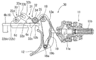
次に、本発明の実施形態を図1〜図26に基づいて説明する。図1及び図2に示すように本実施形態では、打ち込み工具1の一例として圧縮エア駆動式の釘打ち機を例示する。この打ち込み工具1は、圧縮エアを動力源としてシリンダ15内を上下に往復動するピストン13を内装した工具本体部2と、工具本体部2の側部から側方へ突き出す状態に設けられたグリップ部3と、工具本体部2の下部から下方(打ち込み具の打ち込み方向)に延びる打ち込みノーズ部4と、打ち込みノーズ部4とグリップ部3との間に跨って装備されて多数本の打ち込み具を装填可能なマガジン5を備えている。 Next, an embodiment of the present invention will be described with reference to FIGS. 1 to 26. As shown in FIGS. 1 and 2, in the present embodiment, a compressed air-driven nail gun is illustrated as an example of the driving tool 1. The driving tool 1 includes a tool body 2 having a piston 13 that reciprocates up and down in the cylinder 15 using compressed air as a power source, and a grip provided so as to project laterally from the side of the tool body 2. A large number of driving tools are provided so as to straddle the portion 3, the driving nose portion 4 extending downward (the driving direction of the driving tool) from the lower part of the tool body portion 2, and the driving nose portion 4 and the grip portion 3. It has a loadable magazine 5.

打ち込みノーズ部4の先端にコンタクトアーム6が上下に相対変位可能に支持されている。コンタクトアーム6を打ち込み材Wに押し付けて相対的に上動させることが打ち込み動作を行うための一つの条件となっている。コンタクトアーム6は、打ち込みノーズ部4の先端付近からトリガ12付近に至る範囲に延びている。コンタクトアーム6の下部には、打ち込みノーズ部4の先端であって射出口周辺に位置する円環形状の当接部6aが設けられている。コンタクトアーム6の上部には、トリガ12に向けて延びる帯板形状の延長部6bが設けられている。当接部6aと延長部6bを一体に有するコンタクトアーム6が打ち込みノーズ部4に沿って上下に一定の範囲で変位可能に支持されている。 A contact arm 6 is supported at the tip of the driving nose portion 4 so as to be relatively displaceable up and down. It is one of the conditions for performing the driving operation that the contact arm 6 is pressed against the driving material W and moved upward relatively. The contact arm 6 extends from the vicinity of the tip of the driving nose portion 4 to the vicinity of the trigger 12. A ring-shaped contact portion 6a, which is the tip of the driving nose portion 4 and is located around the injection port, is provided at the lower portion of the contact arm 6. A strip-shaped extension portion 6b extending toward the trigger 12 is provided on the upper portion of the contact arm 6. A contact arm 6 having an abutting portion 6a and an extension portion 6b integrally is supported so as to be displaceable in a certain range up and down along the driving nose portion 4.

グリップ部3の基部付近であって工具本体部2の側部に、本実施形態に係る起動装置10が配置されている。起動装置10の起動操作により起動バルブ11がオンする。起動バルブ11がオンすると、工具本体部2のピストン上室16に圧縮エアが供給される。ピストン上室16に圧縮エアが供給されると、ピストン13がシリンダ15内を下動して打ち込み動作がなされる。ピストン13の下面には長尺棒状の打撃ドライバ14が取り付けられている。この打撃ドライバ14がピストン13の下動に伴って打ち込みノーズ部4内を下動することにより、1本の打ち込み具が打ち込みノーズ部4の先端(射出口)から打ち出される。打ち込みノーズ部4内には、マガジン5から打ち込み具が1本ずつ供給される。 The activation device 10 according to the present embodiment is arranged near the base of the grip portion 3 and on the side portion of the tool main body portion 2. The start valve 11 is turned on by the start operation of the start device 10. When the start valve 11 is turned on, compressed air is supplied to the piston upper chamber 16 of the tool body 2. When compressed air is supplied to the piston upper chamber 16, the piston 13 moves downward in the cylinder 15 to perform a driving operation. A long rod-shaped striking driver 14 is attached to the lower surface of the piston 13. When the striking driver 14 moves downward in the driving nose portion 4 as the piston 13 moves downward, one driving tool is launched from the tip (injection port) of the driving nose portion 4. A driving tool is supplied one by one from the magazine 5 into the driving nose portion 4.

図1に示すように起動装置10の側部には、トリガロックレバー7が設けられている。このトリガロックレバー7を図1に示すように下側に回動操作した状態では、トリガ12を上方へ引き操作可能となる。トリガロックレバー7を上側へ回動操作した状態では、トリガ12の上方への引き操作ができないトリガロック状態となる。トリガロックレバー7を上側のロック位置に切り替えておくことにより、当該打ち込み工具1の不用意な打ち込み動作を未然に防ぐことができる。 As shown in FIG. 1, a trigger lock lever 7 is provided on the side of the starting device 10. In the state where the trigger lock lever 7 is rotated downward as shown in FIG. 1, the trigger 12 can be pulled upward. In the state where the trigger lock lever 7 is rotated upward, the trigger lock state is such that the trigger 12 cannot be pulled upward. By switching the trigger lock lever 7 to the upper lock position, it is possible to prevent the inadvertent driving operation of the driving tool 1 in advance.

本実施形態は、起動装置10について従来にない特徴を備えている。打ち込み工具1の基本的構成については本実施形態において特に変更を要しないので詳細な説明は省略する。起動装置10は、トリガ12のオン操作とコンタクトアーム6のオン操作の双方がなされたことを条件に起動バルブ11をオンさせる機能を有している。本実施形態の起動装置10は、上記した起動バルブ11と、トリガ12と、タイマー機構20を備えている。図2に示すように起動バルブ11はグリップ部3の基部側下面に収容されている。バルブステム11aの下部がトリガ12に向けて突き出されている。起動バルブ11のバルブステム11aは上下(オン位置とオフ位置)に移動可能に支持されている。バルブステム11aは、圧縮ばね11bにより下方のオフ位置側へ移動する方向に付勢されている。図2はバルブステム11aがオフ位置に位置する状態を示している。バルブステム11aがこのオフ位置からばね付勢力に抗して上動することにより起動バルブ11がオンする。 This embodiment has features that the activation device 10 does not have in the past. Since the basic configuration of the driving tool 1 does not need to be changed in this embodiment, detailed description thereof will be omitted. The activation device 10 has a function of turning on the activation valve 11 on condition that both the on operation of the trigger 12 and the on operation of the contact arm 6 are performed. The activation device 10 of the present embodiment includes the activation valve 11, the trigger 12, and the timer mechanism 20 described above. As shown in FIG. 2, the start valve 11 is housed in the lower surface of the grip portion 3 on the base side. The lower part of the valve stem 11a protrudes toward the trigger 12. The valve stem 11a of the start valve 11 is movably supported up and down (on position and off position). The valve stem 11a is urged by the compression spring 11b in a direction of moving downward to the off position side. FIG. 2 shows a state in which the valve stem 11a is located in the off position. The start valve 11 is turned on by the valve stem 11a moving upward against the spring urging force from this off position.

起動バルブ11がオンすると、ヘッドバルブ2eが下向きに作用するエア圧により下方へ変位して開かれる。ヘッドバルブ2eが開かれるとグリップ部3内の蓄圧室3aに蓄圧された圧縮エアがピストン上室16に供給される。バルブステム11aがばね付勢力で下方へ戻されると、起動バルブ11がオフする。起動バルブ11がオフすると、ヘッドバルブ2eが上向きに作用するエア圧及びばね力により上方へ変位し、これによりピストン上室16が蓄圧室3aに対して閉じられる。ピストン上室16は閉じられると同時に大気開放され、これより下動したピストン13が上死点(初期位置)に戻される。 When the start valve 11 is turned on, the head valve 2e is displaced downward and opened by the air pressure acting downward. When the head valve 2e is opened, the compressed air accumulated in the accumulator chamber 3a in the grip portion 3 is supplied to the piston upper chamber 16. When the valve stem 11a is returned downward by the spring-forced force, the start valve 11 is turned off. When the start valve 11 is turned off, the head valve 2e is displaced upward by the air pressure and the spring force acting upward, whereby the piston upper chamber 16 is closed with respect to the accumulator chamber 3a. The piston upper chamber 16 is closed and opened to the atmosphere at the same time, and the piston 13 that has moved downward is returned to the top dead center (initial position).

トリガ12とタイマー機構20の詳細が図3〜図7に示されている。トリガ12とタイマー機構20は、工具本体部2の後面側に一体に設けられた起動ベース17に支持されている。トリガ12は、支軸18を介して上下に回動操作可能に支持されている。トリガ12は、グリップ部3を把持した手の指先で上方(オン位置)へ引き操作される。トリガ12は、捩じりばね12aにより下方のオフ位置側へ回動する方向に付勢されている。トリガ12の背面側(上面側)には、アイドラ19が支軸19aを介して上下に回動可能に支持されている。アイドラ19は、捩じりばね19bにより回動先端側(前側)を上方へ変位させる方向に付勢されている。捩じりばね19bの付勢力により、アイドラ19は常時起動バルブ11のバルブステム11aの先端に押し付けられた状態となっている。 Details of the trigger 12 and the timer mechanism 20 are shown in FIGS. 3 to 7. The trigger 12 and the timer mechanism 20 are supported by a start-up base 17 integrally provided on the rear surface side of the tool body 2. The trigger 12 is supported so as to be rotatable up and down via a support shaft 18. The trigger 12 is pulled upward (on position) by the fingertip of the hand holding the grip portion 3. The trigger 12 is urged by a torsion spring 12a in a direction of rotating downward to the off position side. An idler 19 is rotatably supported on the back surface side (upper surface side) of the trigger 12 via a support shaft 19a. The idler 19 is urged by a torsion spring 19b in a direction in which the rotation tip side (front side) is displaced upward. Due to the urging force of the torsion spring 19b, the idler 19 is constantly pressed against the tip of the valve stem 11a of the start valve 11.

トリガ12の下側にタイマー機構20が設けられている。タイマー機構20の後方に沿ってコンタクトアーム6の延長部6bが上下に変位可能に配置されている。タイマー機構20は、トリガ12の下側において起動ベース17に支持されたコンタクト規制部材21と、コンタクト規制部材21の下側において、同じく起動ベース17に支持されたタイマー設定部22を備えている。コンタクト規制部材21は、支軸23を介して前後に回動可能に支持されている。コンタクト規制部材21は、支軸23に支持された円筒形の支持筒部21aに、ギヤアーム部21bとストッパ部21cと解除アーム部21dを一体に備えた構成を有している。ギヤアーム部21bは支持筒部21aの右端部から概ね下方へ向けて延びている。ギヤアーム部21bの左側部にロック部21eが一体に設けられている。図示するようにロック部21eは、ブロック体形を有してギヤアーム部21bの左側部から側方へ突き出す状態に設けられている。ストッパ部21cは、支持筒部21aの右端部からギヤアーム部21bに対して支軸23の軸回りに約90°の間隔をおいて概ね後方へ張り出している。解除アーム部21dは、支持筒部21aの左端部からギヤアーム部21bに対して支軸23の軸回りに約45°の間隔をおいて概ね斜め下方に延びている。支持筒部21aの軸線回りの位置について、ギヤアーム部21bとストッパ部21cと解除アーム部21dの相互の位置関係は固定されており、一体で支軸23の軸回りに変位する。 A timer mechanism 20 is provided below the trigger 12. An extension portion 6b of the contact arm 6 is arranged so as to be vertically displaceable along the rear side of the timer mechanism 20. The timer mechanism 20 includes a contact regulating member 21 supported by the activation base 17 on the lower side of the trigger 12, and a timer setting unit 22 also supported by the activation base 17 on the lower side of the contact regulating member 21. The contact regulating member 21 is rotatably supported back and forth via a support shaft 23. The contact restricting member 21 has a configuration in which a gear arm portion 21b, a stopper portion 21c, and a release arm portion 21d are integrally provided on a cylindrical support cylinder portion 21a supported by a support shaft 23. The gear arm portion 21b extends substantially downward from the right end portion of the support cylinder portion 21a. A lock portion 21e is integrally provided on the left side portion of the gear arm portion 21b. As shown in the figure, the lock portion 21e has a block body shape and is provided so as to protrude laterally from the left side portion of the gear arm portion 21b. The stopper portion 21c projects rearward from the right end portion of the support cylinder portion 21a with respect to the gear arm portion 21b at an interval of about 90 ° around the axis of the support shaft 23. The release arm portion 21d extends substantially obliquely downward from the left end portion of the support cylinder portion 21a with respect to the gear arm portion 21b at an interval of about 45 ° around the axis of the support shaft 23. Regarding the position of the support cylinder portion 21a around the axis, the mutual positional relationship between the gear arm portion 21b, the stopper portion 21c, and the release arm portion 21d is fixed, and the support cylinder portion 21a is integrally displaced around the axis of the support shaft 23.

コンタクト規制部材21は、捩じりばね24により、図6において反時計回り方向(コンタクトロック側)に付勢されている。トリガ12の下面には、ストッパ受け部12bが設けられている。ストッパ受け部12bは、ストッパ部21cの上方に位置している。図6に示すようにトリガ12が下側のオフ位置に位置する状態では、ストッパ部21cがストッパ受け部12bで下方へ押されてコンタクト規制部材21が捩じりばね24に抗して時計回り方向に回動した初期位置に保持される。コンタクト規制部材21が初期位置に位置する状態では、解除アーム部21dがコンタクトアーム6の延長部6bに対して前側(図6において上側)へ変位した状態となる。 The contact restricting member 21 is urged in the counterclockwise direction (contact lock side) in FIG. 6 by the torsion spring 24. A stopper receiving portion 12b is provided on the lower surface of the trigger 12. The stopper receiving portion 12b is located above the stopper portion 21c. As shown in FIG. 6, when the trigger 12 is located at the lower off position, the stopper portion 21c is pushed downward by the stopper receiving portion 12b, and the contact restricting member 21 rotates clockwise against the torsion spring 24. It is held in the initial position rotated in the direction. When the contact restricting member 21 is located at the initial position, the release arm portion 21d is displaced to the front side (upper side in FIG. 6) with respect to the extension portion 6b of the contact arm 6.

コンタクトアーム6の延長部6bには、ロック受け部6cと解除案内部6dが設けられている。図5に示すようにロック受け部6cは、延長部6bの右側部に凹形に切り欠かれて設けられている。解除案内部6dは、延長部6bの左側部に設けられている。解除案内部6dは、当該延長部6bの板厚方向に傾斜した傾斜面で、下側ほど前側へ変位する方向に傾斜した状態に設けられている。 The extension portion 6b of the contact arm 6 is provided with a lock receiving portion 6c and a release guide portion 6d. As shown in FIG. 5, the lock receiving portion 6c is provided in a concave shape on the right side portion of the extension portion 6b. The release guide portion 6d is provided on the left side portion of the extension portion 6b. The release guide portion 6d is an inclined surface of the extension portion 6b inclined in the plate thickness direction, and is provided in a state of being inclined in a direction of being displaced toward the front side toward the lower side.

コンタクトアーム6がオン操作されていない状態で、コンタクト規制部材21がロック側(図6において反時計回り方向)に回動してロック部21eがコンタクトアーム6のロック受け部6cに進入することにより、当該コンタクトアーム6のオン操作が禁止された状態となる。 When the contact arm 6 is not turned on, the contact restricting member 21 rotates to the lock side (counterclockwise in FIG. 6) and the lock portion 21e enters the lock receiving portion 6c of the contact arm 6. , The on operation of the contact arm 6 is prohibited.

これに対して、コンタクト規制部材21がロック位置(ロック部21eをロック受け部6cに進入させた位置)に至るまでの間に、コンタクトアーム6がオン操作されると、解除アーム部21dの回動先端部が解除案内部6dに当接され、この当接状態でコンタクトアーム6がオン操作(上動)されることにより、解除アーム部21dが解除案内部6dの傾斜作用により前方へ押され、従ってコンタクト規制部材21が初期位置に戻されることから、コンタクトアーム6のオン位置側への移動操作(オン操作)が許容される。 On the other hand, if the contact arm 6 is turned on before the contact restricting member 21 reaches the lock position (the position where the lock portion 21e is inserted into the lock receiving portion 6c), the release arm portion 21d is rotated. The moving tip is brought into contact with the release guide 6d, and the contact arm 6 is turned on (upward) in this contact state, so that the release arm 21d is pushed forward by the tilting action of the release guide 6d. Therefore, since the contact restricting member 21 is returned to the initial position, the movement operation (on operation) of the contact arm 6 to the on position side is allowed.

コンタクト規制部材21の下方にタイマー設定部22が配置されている。タイマー設定部22は、コンタクト規制部材21のギヤアーム部21bに噛み合う中間ギヤ22aとワンウエイクラッチ22bと回転抵抗付与部材22cを備えている。回転抵抗付与部材22cはいわゆるロータリーダンパで、その作動軸22dには封入したシリコン油により軸回り両方向に一定の回転抵抗が与えられている。中間ギヤ22aとワンウエイクラッチ22bは、回転抵抗付与部材22cの作動軸22d上に支持されている。作動軸22dは、図7においてのみ見えている。ワンウエイクラッチ22bの受け側22bcは、作動軸22dに対して軸方向及び軸回りに固定されている。 A timer setting unit 22 is arranged below the contact regulating member 21. The timer setting unit 22 includes an intermediate gear 22a, a one-way clutch 22b, and a rotation resistance imparting member 22c that mesh with the gear arm portion 21b of the contact restricting member 21. The rotation resistance imparting member 22c is a so-called rotary damper, and a constant rotation resistance is given to the operating shaft 22d by the sealed silicon oil in both directions around the shaft. The intermediate gear 22a and the one-way clutch 22b are supported on the operating shaft 22d of the rotation resistance imparting member 22c. The working shaft 22d is visible only in FIG. The receiving side 22bc of the one-way clutch 22b is fixed in the axial direction and around the axis with respect to the operating shaft 22d.

中間ギヤ22aはワンウエイクラッチ22bの駆動側22bbに一体に設けられている。ワンウエイクラッチ22bの駆動側22bbと中間ギヤ22aは、作動軸22dに対して軸方向に変位可能かつ軸回りについては一体化(スプライン嵌合)されている。ワンウエイクラッチ22bの駆動側22bbと中間ギヤ22aは、圧縮ばね22eにより、当該駆動側22bbを受け側22baに噛み合わせる左方向(図7において紙面下向き)に付勢されている。コンタクト規制部材21のギヤアーム部21bの回動動作は、中間ギヤ22a及びワンウエイクラッチ22bを経て回転抵抗付与部材22cの作動軸22dに伝達される。 The intermediate gear 22a is integrally provided on the drive side 22bb of the one-way clutch 22b. The drive side 22bb of the one-way clutch 22b and the intermediate gear 22a are displaceable in the axial direction with respect to the operating shaft 22d and are integrated (spline fitting) around the shaft. The drive side 22bb and the intermediate gear 22a of the one-way clutch 22b are urged by the compression spring 22e in the left direction (downward on the paper surface in FIG. 7) in which the drive side 22bb meshes with the receiving side 22ba. The rotational operation of the gear arm portion 21b of the contact restricting member 21 is transmitted to the operating shaft 22d of the rotational resistance applying member 22c via the intermediate gear 22a and the one-way clutch 22b.

ワンウエイクラッチ22bのトルク伝達方向は、ギヤアーム部21bが下方へ移動する際の回転トルクを駆動側22bbから受け側22baに伝達する一方、ギヤアーム部21bの上方への戻し動作については駆動側22bbが受け側baに対して相対回転してトルクを伝達しない方向に設定されている。このため、タイマー作動時におけるギヤアーム部21bのロック位置側(図6において時計回り方向)への回動動作について回転抵抗付与部材22cにより一定の回転抵抗が持たせられる一方、タイマー解除時におけるギヤアーム部21bのアンロック位置側(図6において反時計回り方向)への回動動作については回転抵抗付与部材22cから切り離されて係る回転抵抗は持たせられない。 In the torque transmission direction of the one-way clutch 22b, the rotational torque when the gear arm portion 21b moves downward is transmitted from the drive side 22bb to the receiving side 22ba, while the drive side 22bb receives the upward return operation of the gear arm portion 21b. It is set in a direction in which torque is not transmitted by rotating relative to the side ba. Therefore, the rotation resistance imparting member 22c provides a constant rotation resistance for the rotation operation of the gear arm portion 21b toward the lock position side (clockwise in FIG. 6) when the timer is activated, while the gear arm portion when the timer is released. Regarding the rotational operation of 21b toward the unlock position side (counterclockwise direction in FIG. 6), the rotational resistance is not provided by being separated from the rotational resistance imparting member 22c.

トリガ12のオン操作後におけるコンタクト規制部材21の動作についてタイマー設定部22の回転抵抗付与部材22cにより一定の動作抵抗が与えられることにより、ロック部21eがロック受け部6cに進入してコンタクトアーム6のオン操作がロックされるまでに必要な一定時間(基準時間t)が設定されている。このように構成されたタイマー機構20がトリガ12とコンタクトアーム6の延長部6bとの間に介在されることにより、トリガ12のオン操作状態における不用意な打ち込み動作が防止される。 Regarding the operation of the contact restricting member 21 after the trigger 12 is turned on, the lock portion 21e enters the lock receiving portion 6c and the contact arm 6 is provided by the rotation resistance imparting member 22c of the timer setting unit 22. A fixed time (reference time t) required for the on operation of is locked is set. By interposing the timer mechanism 20 configured in this way between the trigger 12 and the extension portion 6b of the contact arm 6, careless driving operation in the on-operation state of the trigger 12 is prevented.

トリガ12及びコンタクトアーム6がそれぞれオン操作されると、アイドラ19によりステム11aが上方へ押されて起動バルブ11がオンする。前記したように起動バルブ11がオンすることによりピストン上室16に圧縮エアが供給されて打ち込み動作がなされる。例えば、先にトリガ12をオン操作し、その後コンタクトアーム6をオン操作して行う打ち込み作業形態(例えば連発打ち)では、トリガ12のオン操作後、上記タイマー機構20により設定された基準時間tの経過後にコンタクトアーム6のオン操作が禁止される。コンタクトアーム6のオン操作禁止状態は、トリガ12のオン操作を解除することによりリセットされる。また、例えば先にコンタクトアーム6をオン操作し、その後トリガ12をオン操作して行う打ち込み作業形態(例えば単発打ち)では、上記タイマー機構20による時間的制約は発生しない。以下、各作業形態についてタイマー機構20の動作状態を説明する。 When the trigger 12 and the contact arm 6 are turned on, the idler 19 pushes the stem 11a upward and the start valve 11 is turned on. When the start valve 11 is turned on as described above, compressed air is supplied to the piston upper chamber 16 to perform a driving operation. For example, in the driving operation mode (for example, continuous striking) in which the trigger 12 is turned on first and then the contact arm 6 is turned on, the reference time t set by the timer mechanism 20 is set after the trigger 12 is turned on. After that, the contact arm 6 is prohibited from being turned on. The ON operation prohibition state of the contact arm 6 is reset by releasing the ON operation of the trigger 12. Further, for example, in the driving operation mode (for example, single shot) in which the contact arm 6 is turned on first and then the trigger 12 is turned on, the time constraint by the timer mechanism 20 does not occur. Hereinafter, the operating state of the timer mechanism 20 will be described for each work mode.

先ず、連発打ちを行うために図8に示す初期位置から、図9に示すようにトリガ12を上方へ引き操作するとタイマー機構20が作動する。トリガ12を上方へ引き操作するとストッパ受け部12bが上方へ変位する結果、ストッパ部21cが上方へ変位可能となる。ストッパ部21cが上方へ変位可能となると、図10に示すようにコンタクト規制部材21が捩じりばね24によりロック側(図10において反時計回り方向)に回動する。コンタクト規制部材21がロック側に回転すると、解除アーム部21dとロック部21eが一体で後方に変位する。 First, the timer mechanism 20 is activated when the trigger 12 is pulled upward as shown in FIG. 9 from the initial position shown in FIG. 8 for continuous striking. When the trigger 12 is pulled upward, the stopper receiving portion 12b is displaced upward, and as a result, the stopper portion 21c can be displaced upward. When the stopper portion 21c can be displaced upward, the contact restricting member 21 is rotated to the lock side (counterclockwise in FIG. 10) by the torsion spring 24 as shown in FIG. When the contact restricting member 21 rotates to the lock side, the release arm portion 21d and the lock portion 21e are integrally displaced rearward.

図12に示すようにコンタクト規制部材21のロック側への回動端位置は、そのストッパ部21cがオン位置に位置するトリガ12のストッパ受け部12bに当接することにより規制される。また、コンタクト規制部材21のロック側への回動動作については、タイマー設定部22により一定の回転抵抗が付与されて、図12に示すロック側への回動端位置に至るまでに要する基準時間tが設定されている。図11は、トリガ12のオン操作後であってタイマー機構20が作動し始めてから基準時間tが経過する前にコンタクトアーム6をオン操作した状態が示されている。 As shown in FIG. 12, the position of the rotating end of the contact restricting member 21 toward the lock side is regulated by the stopper portion 21c coming into contact with the stopper receiving portion 12b of the trigger 12 located at the on position. Further, regarding the rotation operation of the contact regulating member 21 toward the lock side, a constant rotation resistance is applied by the timer setting unit 22, and the reference time required to reach the rotation end position toward the lock side shown in FIG. t is set. FIG. 11 shows a state in which the contact arm 6 is turned on after the trigger 12 is turned on and before the reference time t elapses after the timer mechanism 20 starts operating.

図11に示すように基準時間t経過前にコンタクトアーム6がオン操作されると、コンタクト規制部材21の解除アーム部21dが解除案内部6dに当接した状態となる。解除アーム部21dの先端部が解除案内部6dに当接した状態でコンタクトアーム6が上方へ変位することにより、解除アーム部21dが解除案内部6dの傾斜面作用により前方へ押され、その結果コンタクト規制部材21が図11において白抜き矢印で示すように時計回り方向(アンロック側)に回動して初期位置に戻される。コンタクト規制部材21のアンロック側への回転動作については、タイマー設定部22においてワンウエイクラッチ22bにより回転抵抗付与部材22cが切り離されるため、当該コンタクト規制部材21は回転抵抗を受けることなく迅速にアンロック側(初期位置側)に戻される。コンタクト規制部材21がアンロック側に戻されるためコンタクトアーム6をオン位置まで操作することができる。図11に示すようにトリガ12がオン操作された状態で基準時間t経過前にコンタクトアーム6がオン操作されることにより、アイドラ19がコンタクトアーム6の延長部6bにより所定のオン位置まで押されて起動バルブ11がオンし、これにより工具本体部2において打ち込み動作がなされる。 As shown in FIG. 11, when the contact arm 6 is turned on before the elapse of the reference time t, the release arm portion 21d of the contact restricting member 21 is in contact with the release guide portion 6d. When the contact arm 6 is displaced upward while the tip of the release arm portion 21d is in contact with the release guide portion 6d, the release arm portion 21d is pushed forward by the inclined surface action of the release guide portion 6d, and as a result. The contact restricting member 21 rotates in the clockwise direction (unlocked side) as shown by a white arrow in FIG. 11 and is returned to the initial position. Regarding the rotational operation of the contact restricting member 21 to the unlock side, the one-way clutch 22b disconnects the rotational resistance applying member 22c in the timer setting unit 22, so that the contact restricting member 21 is quickly unlocked without receiving rotational resistance. It is returned to the side (initial position side). Since the contact restricting member 21 is returned to the unlock side, the contact arm 6 can be operated to the on position. As shown in FIG. 11, when the contact arm 6 is turned on before the reference time t elapses while the trigger 12 is turned on, the idler 19 is pushed to a predetermined on position by the extension portion 6b of the contact arm 6. The start valve 11 is turned on, whereby the driving operation is performed in the tool body 2.

トリガ12のオン操作後、基準時間tの経過前にコンタクトアーム6がオン操作されないと、図12に示すようにコンタクト規制部材21のロック部21eがロック受け部6cに進入した状態となる。ロック部21eがロック受け部6cに進入した状態では、コンタクトアーム6のそれ以上の上方への変位が規制されるためアイドラ19がオン位置まで押されず、従って起動バルブ11がオンしないため打ち込み動作はなされない。 If the contact arm 6 is not turned on after the trigger 12 is turned on and before the reference time t elapses, the lock portion 21e of the contact restricting member 21 is in a state of entering the lock receiving portion 6c as shown in FIG. In the state where the lock portion 21e has entered the lock receiving portion 6c, the idler 19 is not pushed to the on position because the displacement of the contact arm 6 further upward is restricted, and therefore the start valve 11 does not turn on, so that the driving operation is performed. Not done.

このように、先にトリガ12をオン操作して行う連発打ちにおいて、トリガ12のオン操作後、基準時間t経過後におけるコンタクトアーム6のオン操作が禁止される。これにより、トリガ12を引き操作したまま当該打ち込み工具1を持ち運ぶ際における不用意な打ち込み動作を確実に防止することができる。上記例示したタイマー機構20では、ロータリーダンパとも称される回転抵抗付与部材22cによりコンタクト規制部材21の回転動作にのみ抵抗を与えて基準時間tの設定がなされる構成であり、例えば圧縮エアを動力源とする動作部を介在させない構成であるので、当該タイマー機構20をスムーズに動作させることができる。 As described above, in the continuous striking performed by turning on the trigger 12 first, the on operation of the contact arm 6 after the on operation of the trigger 12 and the elapse of the reference time t is prohibited. As a result, it is possible to reliably prevent an inadvertent driving operation when carrying the driving tool 1 while pulling the trigger 12. The timer mechanism 20 illustrated above has a configuration in which the rotation resistance imparting member 22c, which is also called a rotary damper, gives resistance only to the rotational operation of the contact regulating member 21 to set the reference time t, for example, powering compressed air. Since the configuration is such that the moving unit as the source is not interposed, the timer mechanism 20 can be operated smoothly.

上記したように先にトリガ12をオン操作して行う連発打ちにおいては、タイマー機構20が作動して工具本体部2の不用意な打ち込み動作が禁止される。本実施形態に係る打ち込み工具1は、先にコンタクトアーム6をオン操作しても打ち込み動作がなされる。先にコンタクトアーム6をオン操作して行う単発打ちにおいては、タイマー機構20は作動しない。単発打ちでは、先にコンタクトアーム6がオン操作され、その後使用者による明確な意図をもってトリガ12がオン操作されるため、工具本体部2において不用意な打ち込み動作がなされることを想定する必要性は低い。 As described above, in the continuous striking performed by first turning on the trigger 12, the timer mechanism 20 operates to prohibit the careless striking operation of the tool body 2. The driving tool 1 according to the present embodiment can be driven even if the contact arm 6 is turned on first. The timer mechanism 20 does not operate in the single-shot striking performed by first turning on the contact arm 6. In a single shot, the contact arm 6 is turned on first, and then the trigger 12 is turned on with a clear intention by the user. Therefore, it is necessary to assume that a careless driving operation is performed in the tool body 2. Is low.

単発打ちでは、図8に示す初期位置から、図13に示すように先にコンタクトアーム6がオン操作される。トリガ12がオン操作されていないため、そのストッパ受け部12bがストッパ部21cを下方へ押した状態(図13では見えていない)であるため、コンタクト規制部材21が初期位置に位置する状態のままとなっている。このため、解除アーム部21dは、コンタクトアーム6の延長部6bの移動経路から前側へ外れた位置に保持され、かつロック部21eはロック受け部6cに対して前方へ大きく外れた位置に保持された状態となっている。コンタクト規制部材21により移動を規制されない状態であるので、コンタクトアーム6の延長部6bは図13に示すようにオン位置まで移動してアイドラ19をオン位置まで押し上げた状態となる。 In the single shot, the contact arm 6 is turned on first as shown in FIG. 13 from the initial position shown in FIG. Since the trigger 12 is not turned on, the stopper receiving portion 12b pushes the stopper portion 21c downward (not visible in FIG. 13), so that the contact restricting member 21 remains in the initial position. It has become. Therefore, the release arm portion 21d is held at a position deviated forward from the movement path of the extension portion 6b of the contact arm 6, and the lock portion 21e is held at a position significantly deviated forward with respect to the lock receiving portion 6c. It is in a state of being. Since the movement is not restricted by the contact restricting member 21, the extension portion 6b of the contact arm 6 moves to the on position and pushes up the idler 19 to the on position as shown in FIG.

図13に示すようにコンタクトアーム6がオン操作された後、図14に示すようにトリガ12をオン操作するとバルブステム11aが上方へ押されて起動バルブ11がオンする。起動バルブ11がオンすることにより、工具本体部2において打ち込み動作がなされる。単発打ちでは、1回の打ち込み動作がなされた後には、トリガ12がオフ位置に戻され、かつコンタクトアーム6がオフ位置に戻されて当該打ち込み工具1が一旦初期状態に戻される。 After the contact arm 6 is turned on as shown in FIG. 13, when the trigger 12 is turned on as shown in FIG. 14, the valve stem 11a is pushed upward and the starting valve 11 is turned on. When the start valve 11 is turned on, a driving operation is performed in the tool body 2. In the single-shot driving, the trigger 12 is returned to the off position and the contact arm 6 is returned to the off position after one driving operation is performed, and the driving tool 1 is temporarily returned to the initial state.

単発打ちにおいて、1回の打ち込み動作がなされた後に、図15に示すようにトリガ12をオン操作したままコンタクトアーム6のオン操作のみを解除すると、連発打ちの作業形態に切り替わる。図15では、連発打ちにおいてトリガ12を先にオン操作し、コンタクトアーム6をオン操作する前の状態を示す図9と同じ状態が示されている。1回の単発打ち後に、トリガ12をオン操作したままコンタクトアーム6をオフ操作すると、解除アーム部21dの後方からコンタクトアーム6の延長部6bが退避するため、コンタクト規制部材21がロック側へ回動可能な状態となる。また、トリガ12がオン操作されたままであることから、ストッパ受け部12bがストッパ部21cから上方へ離間した状態となっている。このため、単発打ちにおいて1回の打ち込み動作後、コンタクトアーム6をオフ位置に戻すと、タイマー機構20が作動し始める。具体的には、前記連発打ちと同じくコンタクト規制部材21がロック側へ回動し始める。このため、その後基準時間tを経過する前に再びコンタクトアーム6をオン操作することにより連発打ちを行うことができる。基準時間tが経過した後には、コンタクトアーム6のオン操作が禁止されることにより不用意な打ち込み動作が禁止される。 In the single-shot striking, if only the on-operation of the contact arm 6 is released while the trigger 12 is on-operated as shown in FIG. 15 after one striking operation is performed, the working mode is switched to the continuous striking work mode. FIG. 15 shows the same state as in FIG. 9, which shows a state before the trigger 12 is turned on first and the contact arm 6 is turned on in the continuous striking. If the contact arm 6 is turned off while the trigger 12 is turned on after one single hit, the extension portion 6b of the contact arm 6 retracts from behind the release arm portion 21d, so that the contact restricting member 21 rotates to the lock side. It becomes movable. Further, since the trigger 12 is still on, the stopper receiving portion 12b is separated from the stopper portion 21c upward. Therefore, when the contact arm 6 is returned to the off position after one driving operation in a single shot, the timer mechanism 20 starts to operate. Specifically, the contact restricting member 21 starts to rotate toward the lock side as in the case of the continuous striking. Therefore, the continuous striking can be performed by turning on the contact arm 6 again before the reference time t elapses. After the reference time t has elapsed, the contact arm 6 is prohibited from being turned on, so that a careless driving operation is prohibited.

タイマー機構20による打ち込み動作禁止状態(コンタクトアーム6のオン操作禁止状態)は、トリガ12のオン操作を一旦解除することによりリセットすることができる。トリガ12をオフ位置に戻すと、そのストッパ受け部12bによりストッパ部21cが下方へ押されて、コンタクト規制部材21が捩じりばね24の付勢力に抗して初期位置に戻されて、当該起動装置10が図8に示す初期状態にリセットされる。 The driving operation prohibited state by the timer mechanism 20 (the ON operation prohibited state of the contact arm 6) can be reset by once canceling the ON operation of the trigger 12. When the trigger 12 is returned to the off position, the stopper portion 21c is pushed downward by the stopper receiving portion 12b, and the contact restricting member 21 is returned to the initial position against the urging force of the torsion spring 24. The activation device 10 is reset to the initial state shown in FIG.

以上のように構成した第1実施形態に係る起動装置10によれば、トリガ12がオン操作され、コンタクトアーム6がオン操作されていない状態ではタイマー機構20が作動する。このため、例えば連発打ちを行うためトリガ12をオン操作したまま当該打ち込み工具1を持ち運ぶ際に、基準時間tの経過後であれば誤ってコンタクトアーム6を他部位に干渉させる等した場合であっても工具本体部2における不用意な打ち込み動作を防止することができる。 According to the activation device 10 according to the first embodiment configured as described above, the timer mechanism 20 operates when the trigger 12 is turned on and the contact arm 6 is not turned on. For this reason, for example, when carrying the driving tool 1 with the trigger 12 turned on for continuous striking, the contact arm 6 may be mistakenly interfered with another part after the lapse of the reference time t. However, it is possible to prevent an inadvertent driving operation in the tool body 2.

また、第1実施形態に係る起動装置10は、電力を必要とする電気的制御によらず、完全に機械的構成によるタイマー機構20を備えていることから、電力供給のない環境下においても機能させることができる。 Further, since the activation device 10 according to the first embodiment includes a timer mechanism 20 having a completely mechanical configuration regardless of electrical control that requires electric power, it functions even in an environment without electric power supply. Can be made to.

さらに、例示したタイマー装置20では、圧縮エアを動力源として作動する部位を備えないことから、回転抵抗付与部材22cによる回転抵抗を除いて各部のスムーズな動作性(応答性)を確保して、当該打ち込み工具1の作業性(速射性)を高めることができる。 Further, since the timer device 20 illustrated does not have a part that operates by using compressed air as a power source, smooth operability (responsiveness) of each part is ensured except for the rotation resistance by the rotation resistance imparting member 22c. The workability (rapid firing property) of the driving tool 1 can be improved.

以上説明した実施形態には種々変更を加えることができる。例えば図16以降には、第2実施形態のタイマー機構31を備えた起動装置30が示されている。第2実施形態のタイマー機構31は、コンタクト規制部材32とタイマー設定部33との間が、ギヤの噛み合いではなく、リンク機構を介して連携されている点で第1実施形態のタイマー機構20とは異なっている。変更を要しない部材及び構成については同位の符号を用いてその説明を省略する。 Various changes can be made to the embodiments described above. For example, from FIG. 16 onward, the activation device 30 provided with the timer mechanism 31 of the second embodiment is shown. The timer mechanism 31 of the second embodiment is different from the timer mechanism 20 of the first embodiment in that the contact regulating member 32 and the timer setting unit 33 are linked via a link mechanism instead of meshing gears. Is different. The same reference numerals are used for members and configurations that do not require modification, and the description thereof will be omitted.

第2実施形態に係るタイマー機構31は、トリガ12の下側において起動ベース17に支持されたコンタクト規制部材32と、コンタクト規制部材32の下側において、同じく起動ベース17に支持されたタイマー設定部33を備えている。コンタクト規制部材32は、支軸34を介して前後に回動可能に支持されている。コンタクト規制部材32は、捩じりばね35により、図16において反時計回り方向(コンタクトロック側)に付勢されている。コンタクト規制部材32は、支軸34に支持された円筒形の支持筒部32aに、リンクアーム部32bとストッパ部32cとロックアーム部32dを一体に備えた構成を有している。第2実施形態の場合、リンクアーム部32bとストッパ部32cに加えてロックアーム部32dも、支持筒部32aの右端部寄りに配置されている。このため、第2実施形態では、コンタクトアーム6の延長部6bの右端部に沿って解除案内部6dが設けられている。解除案内部6dの上端部にロック受け部6cが設けられている。 The timer mechanism 31 according to the second embodiment has a contact restricting member 32 supported by the activation base 17 on the lower side of the trigger 12 and a timer setting unit similarly supported by the activation base 17 on the lower side of the contact restricting member 32. It has 33. The contact restricting member 32 is rotatably supported back and forth via a support shaft 34. The contact restricting member 32 is urged in the counterclockwise direction (contact lock side) in FIG. 16 by the torsion spring 35. The contact restricting member 32 has a configuration in which a link arm portion 32b, a stopper portion 32c, and a lock arm portion 32d are integrally provided on a cylindrical support cylinder portion 32a supported by a support shaft 34. In the case of the second embodiment, in addition to the link arm portion 32b and the stopper portion 32c, the lock arm portion 32d is also arranged near the right end portion of the support cylinder portion 32a. Therefore, in the second embodiment, the release guide portion 6d is provided along the right end portion of the extension portion 6b of the contact arm 6. A lock receiving portion 6c is provided at the upper end portion of the release guide portion 6d.

ロック受け部6cと解除案内部6dの前方にロックアーム部32dが位置している。コンタクト規制部材32のロック側への回動によりロックアーム部32dがその回動先端部を後方へ変位させる方向に一体で回動して、当該回動先端部がロック受け部6cの上方に進入した状態では、コンタクトアーム6のオン位置側への変位が当該ロックアーム部32dによって規制された状態(コンタクトアームロック状態)となる。これに対して、コンタクトアーム6のロック受け部6cが先にロックアーム部32dの後方を通過し、その結果ロックアーム部32dの回動先端部が解除案内部6dの上面に当接した状態では、解除案内部6dの傾斜作用によりロックアーム部32dが前方へ押されて初期位置側へ戻されることから、コンタクトアーム6のオン位置側への移動操作が許容される状態となる。この点は第1実施形態と同様である。 The lock arm portion 32d is located in front of the lock receiving portion 6c and the release guide portion 6d. Due to the rotation of the contact restricting member 32 toward the lock side, the lock arm portion 32d is integrally rotated in the direction of displacing the rotation tip portion rearward, and the rotation tip portion enters above the lock receiving portion 6c. In this state, the displacement of the contact arm 6 to the on position side is regulated by the lock arm portion 32d (contact arm locked state). On the other hand, in a state where the lock receiving portion 6c of the contact arm 6 first passes behind the lock arm portion 32d, and as a result, the rotating tip portion of the lock arm portion 32d comes into contact with the upper surface of the release guide portion 6d. Since the lock arm portion 32d is pushed forward and returned to the initial position side by the tilting action of the release guide portion 6d, the movement operation of the contact arm 6 to the on position side is permitted. This point is the same as that of the first embodiment.

コンタクト規制部材32の下方にタイマー設定部33が配置されている。第2実施形態のタイマー設定部33は、中間ギヤ22aに代えて中間アーム部33aを備える点以外は第1実施形態のタイマー設定部22と同様に構成されている。同様の部材及び構成については同位の符号を用いる。中間アーム部33aは、ワンウエイクラッチ22bの駆動側22bbに一体に設けられている。中間アーム部33aの先端に設けた連携軸部33bを介して当該中間アーム33aとリンクアーム部32bが相互に反対方向に回転可能に連携されている。中間アーム33aとリンクアーム部32bとの連携、及びワンウエイクラッチ22bを経て回転抵抗付与部材22cの回転抵抗がコンタクト規制部材32に付加される。 A timer setting unit 33 is arranged below the contact regulating member 32. The timer setting unit 33 of the second embodiment is configured in the same manner as the timer setting unit 22 of the first embodiment except that an intermediate arm unit 33a is provided instead of the intermediate gear 22a. Similar codes are used for similar members and configurations. The intermediate arm portion 33a is integrally provided on the drive side 22bb of the one-way clutch 22b. The intermediate arm 33a and the link arm portion 32b are rotatably linked in opposite directions via a linking shaft portion 33b provided at the tip of the intermediate arm portion 33a. The rotation resistance of the rotation resistance imparting member 22c is added to the contact restricting member 32 through the cooperation between the intermediate arm 33a and the link arm portion 32b and the one-way clutch 22b.

トリガ12のオン操作後におけるコンタクト規制部材32の動作についてタイマー設定部33の回転抵抗付与部材22cにより一定の動作抵抗が与えられることにより、ロックアーム部32dがロック受け部6cの上方に進入してコンタクトアーム6のオン操作がロックされるまでに必要な一定時間が設定されている。このように構成されたタイマー機構31がトリガ12とコンタクトアーム6の延長部6bとの間に介在されることにより、トリガ12のオン操作状態における不用意な打ち込み動作が防止される。 Regarding the operation of the contact restricting member 32 after the trigger 12 is turned on, the lock arm portion 32d enters above the lock receiving portion 6c by giving a constant operating resistance by the rotation resistance imparting member 22c of the timer setting unit 33. A certain time is set until the on operation of the contact arm 6 is locked. By interposing the timer mechanism 31 configured in this way between the trigger 12 and the extension portion 6b of the contact arm 6, careless driving operation in the on-operation state of the trigger 12 is prevented.

第2実施形態に係るタイマー機構31を備える起動装置30の動作状態は前記例示した第1実施形態に係るタイマー機構20を備える起動装置10と概ね同様であり、以下簡単に説明する。図18には第2実施形態に係るタイマー機構31を備えた起動装置30の初期状態が示されている。図18以降では、タイマー設定部33の回転抵抗付与部材22c及びワンウエイクラッチ22bの図示が省略されている。また、起動ベース17も省略され、コンタクトアーム6は延長部6bのみが示されている。 The operating state of the activation device 30 including the timer mechanism 31 according to the second embodiment is substantially the same as that of the activation device 10 including the timer mechanism 20 according to the first embodiment described above, and will be briefly described below. FIG. 18 shows an initial state of the activation device 30 provided with the timer mechanism 31 according to the second embodiment. In FIGS. 18 and later, the rotation resistance applying member 22c and the one-way clutch 22b of the timer setting unit 33 are not shown. Further, the activation base 17 is also omitted, and only the extension portion 6b of the contact arm 6 is shown.

図19に示す初期状態から先にトリガ12をオン操作すると、図20に示すようにトリガ12のストッパ受け部12bが上方へ変位してコンタクト規制部材32がロック側へ回転可能な状態となり、これによりタイマー機構31が作動し始める。図21に示すようにタイマー機構31が作動し始めると、コンタクト規制部材32がロック側(図21において反時計回り方向)に回動する。コンタクト規制部材32がロック側へ回動する段階では、リンクアーム部32bと中間アーム部33aとの連携を経て回転抵抗付与部材22cの回転抵抗が当該コンタクト規制部材32の回転動作に付加される。このため、コンタクト規制部材32は、回転抵抗付与部材22cの回転抵抗を受けながら捩じりばね35の付勢力によりロック側へ回転する。 When the trigger 12 is turned on first from the initial state shown in FIG. 19, the stopper receiving portion 12b of the trigger 12 is displaced upward as shown in FIG. 20, and the contact restricting member 32 becomes rotatable toward the lock side. The timer mechanism 31 starts to operate. As shown in FIG. 21, when the timer mechanism 31 starts to operate, the contact restricting member 32 rotates on the lock side (counterclockwise in FIG. 21). At the stage where the contact restricting member 32 rotates to the lock side, the rotational resistance of the rotational resistance imparting member 22c is added to the rotational operation of the contact restricting member 32 through the cooperation between the link arm portion 32b and the intermediate arm portion 33a. Therefore, the contact restricting member 32 rotates toward the lock side by the urging force of the torsion spring 35 while receiving the rotational resistance of the rotational resistance imparting member 22c.

コンタクト規制部材32が、そのストッパ部32cがトリガ12のストッパ受け部12bに当接することにより規制されるロック側の回動端位置に至るまでの間(基準時間tが経過するまでの間)に、コンタクトアーム6がオン操作されると、図22に示すようにアイドラ19が上方へ押されて起動バルブ11がオンし、従って工具本体部2において打ち込み動作がなされる。この際、コンタクト規制部材32のロックアーム部32dがコンタクトアーム6の解除案内面6dに当接した状態でコンタクトアーム6が上動することにより、コンタクト規制部材32がアンロック側に戻される。 Until the contact restricting member 32 reaches the position of the rotation end on the lock side regulated by the stopper portion 32c coming into contact with the stopper receiving portion 12b of the trigger 12 (until the reference time t elapses). When the contact arm 6 is turned on, the idler 19 is pushed upward and the start valve 11 is turned on as shown in FIG. 22, so that the tool body 2 is driven. At this time, the contact arm 6 moves upward while the lock arm portion 32d of the contact restricting member 32 is in contact with the release guide surface 6d of the contact arm 6, so that the contact restricting member 32 is returned to the unlock side.

基準時間tが経過するまでの間にコンタクトアーム6がオン操作されないと、図23に示すようにストッパ部32cがトリガ12のストッパ受け部12bに当接してコンタクト規制部材32がロック側の回動端位置に至る。この状態では、ロックアーム部32dがロック受け部6cの上方に進入した状態となるため、コンタクトアーム6のオン操作が禁止された状態となる。このようにトリガ12のオン操作後、基準時間tが経過する前であればコンタクトアーム6をオン操作して打ち込み動作を行うことができる一方、基準時間tが経過した後にはコンタクトアーム6のオン操作が禁止されて打ち込み動作を行うことができなくなる。これにより、例えばトリガ12をオン操作したまま当該打ち込み工具1を持ち運ぶ際に、基準時間tの経過後にコンタクトアーム6を誤って他部位に接触等させた場合であっても不用意な打ち込み動作がなされることがない。 If the contact arm 6 is not turned on until the reference time t elapses, the stopper portion 32c comes into contact with the stopper receiving portion 12b of the trigger 12 and the contact restricting member 32 rotates on the lock side as shown in FIG. Reach the edge position. In this state, the lock arm portion 32d is in a state of entering above the lock receiving portion 6c, so that the on operation of the contact arm 6 is prohibited. In this way, after the trigger 12 is turned on and before the reference time t has elapsed, the contact arm 6 can be turned on to perform the driving operation, while the contact arm 6 is turned on after the reference time t has elapsed. The operation is prohibited and the driving operation cannot be performed. As a result, for example, when carrying the driving tool 1 with the trigger 12 turned on, even if the contact arm 6 is accidentally brought into contact with another part after the lapse of the reference time t, the driving operation is careless. There is nothing to be done.

タイマー機構31によるコンタクトアーム6のロック状態は、図24に示すようにトリガ12を一旦オフ操作することにより解除することができる。トリガ12をオフ位置に戻すと、そのストッパ受け部12bによりストッパ部32cが下方へ押されることによりコンタクト規制部材32が捩じりばね35の付勢力に抗してアンロック側(図23において時計回り方向)に回動され、最終的に初期位置に戻される。コンタクト規制部材32が初期位置に戻されると、ロックアーム部32dがロック受け部6cの上方から退避するため、コンタクトアーム6をさらに上動させてオン操作できるようになる。 The locked state of the contact arm 6 by the timer mechanism 31 can be released by temporarily turning off the trigger 12 as shown in FIG. 24. When the trigger 12 is returned to the off position, the stopper portion 32c is pushed downward by the stopper receiving portion 12b, so that the contact restricting member 32 is on the unlock side against the urging force of the torsion spring 35 (clock in FIG. 23). It is rotated in the clockwise direction) and finally returned to the initial position. When the contact restricting member 32 is returned to the initial position, the lock arm portion 32d retracts from above the lock receiving portion 6c, so that the contact arm 6 can be further moved upward to perform the on operation.

起動装置30の図24に示す状態は、単発打ちを行うために先にコンタクトアーム6をオン操作した状態に相当する。トリガ12のオフ状態でコンタクトアーム6を打ち込み材Wに押し付けて先にオン操作すると、アイドラ19が上方へ押される。トリガ12がオン操作されていない状態では、そのストッパ受け部12bによりストッパ部32cが下方へ押されてコンタクト規制部材32が初期位置に保持された状態であるためコンタクトアーム6のオン操作が許容される。コンタクトアーム6のオン操作後、図25に示すようにトリガ12をオン操作すると、アイドラ19でステム11aが上方へ押されて起動バルブ11がオンし、従って工具本体部2において打ち込み動作がなされる。 The state shown in FIG. 24 of the activation device 30 corresponds to a state in which the contact arm 6 is first turned on in order to perform a single shot. When the contact arm 6 is pressed against the driving material W in the off state of the trigger 12 and turned on first, the idler 19 is pushed upward. When the trigger 12 is not turned on, the stopper receiving portion 12b pushes the stopper portion 32c downward and the contact restricting member 32 is held in the initial position, so that the contact arm 6 is allowed to be turned on. To. When the trigger 12 is turned on as shown in FIG. 25 after the contact arm 6 is turned on, the stem 11a is pushed upward by the idler 19 and the start valve 11 is turned on, so that the tool body 2 is driven. ..

なお、トリガ12がオン操作されることによりそのストッパ受け部12bによるコンタクト規制部材32の初期位置保持状態は解除されるものの、この段階ではロックアーム部32dがコンタクトアーム6の延長部6bに当接して当該コンタクト規制部材32のロック位置側(図25において反時計回り方向)への回動が規制された状態となっているため、タイマー機構31は作動しない。 When the trigger 12 is turned on, the initial position holding state of the contact restricting member 32 by the stopper receiving portion 12b is released, but at this stage, the lock arm portion 32d comes into contact with the extension portion 6b of the contact arm 6. Since the contact restricting member 32 is restricted from rotating in the lock position side (counterclockwise direction in FIG. 25), the timer mechanism 31 does not operate.

図25に示すようにトリガ12のオン操作で打ち込み動作がなされた後、図26に示すようにトリガ12をオン操作したままコンタクトアーム6をオフ操作すると、タイマー機構31が作動し始める。図26に示す状態は、先にトリガ12をオン操作した結果タイマー機構31が作動し始めた状態を示す図20と同じ状態となっている。このため、図26に示すようにトリガ12をオン操作したままコンタクトアーム6をオフ操作し、基準時間tが経過する前にコンタクトアーム6を再度打ち込み材Wに押し付けてオン操作することにより連発打ちを行うことができる。基準時間tが経過する前にコンタクトアーム6をオン操作しない場合には、タイマー機構32によりコンタクトアーム6のオン操作が禁止された状態となる。係るコンタクトアームロック状態はトリガ12をオフ操作することによりリセットすることができる。 After the driving operation is performed by turning on the trigger 12 as shown in FIG. 25, when the contact arm 6 is turned off while the trigger 12 is turned on as shown in FIG. 26, the timer mechanism 31 starts to operate. The state shown in FIG. 26 is the same as that shown in FIG. 20 showing a state in which the timer mechanism 31 has started to operate as a result of turning on the trigger 12 first. Therefore, as shown in FIG. 26, the contact arm 6 is turned off while the trigger 12 is turned on, and the contact arm 6 is pressed against the driving material W again to be turned on before the reference time t elapses. It can be performed. If the contact arm 6 is not turned on before the reference time t has elapsed, the timer mechanism 32 prohibits the contact arm 6 from being turned on. The contact arm lock state can be reset by turning off the trigger 12.

以上のように構成した第2実施形態に係るタイマー機構31を備えた起動装置30によっても、トリガ12がオン操作され、コンタクトアーム6がオン操作されていない状態ではタイマー機構31が作動するため、例えばトリガ12をオン操作したまま当該打ち込み工具1を持ち運ぶ際に、基準時間tの経過後であれば誤ってコンタクトアーム6を他部位に干渉させる等した場合であっても工具本体部2における不用意な打ち込み動作を防止することができる。 Even with the activation device 30 provided with the timer mechanism 31 according to the second embodiment configured as described above, the timer mechanism 31 operates when the trigger 12 is turned on and the contact arm 6 is not turned on. For example, when carrying the driving tool 1 with the trigger 12 turned on, even if the contact arm 6 is accidentally interfered with another part after the lapse of the reference time t, the tool body 2 does not work. It is possible to prevent a prepared driving operation.

また、第2実施形態に係るタイマー機構31についても、電力を必要とする電気的制御によらず、完全に機械的構成により基準時間tを設定する構成であることから、電力供給のない環境下においても機能させることができる。 Further, the timer mechanism 31 according to the second embodiment also has a configuration in which the reference time t is set by a completely mechanical configuration regardless of the electrical control that requires electric power, so that the timer mechanism 31 is in an environment without electric power supply. Can also function in.

さらに、第2実施形態に係るタイマー装置31も、圧縮エアを動力源として作動する部位を備えないことから、回転抵抗付与部材22cによる回転抵抗を除いて各部の動作の機敏性(応答性)を確保して、当該打ち込み工具1の作業性(速射性)を高めることができる。 Further, since the timer device 31 according to the second embodiment does not have a part that operates by using compressed air as a power source, the agility (responsiveness) of the operation of each part is improved except for the rotation resistance by the rotation resistance imparting member 22c. It is possible to secure and improve the workability (rapid firing property) of the driving tool 1.

以上説明した第1、第2実施形態にはさらに変更を加えることができる。例えば、ロータリーダンパ(回転抵抗付与部材22c)によりコンタクト規制部材21に対して回転方向の抵抗を直接与える構成を例示したが、回転する部材(例えばコンタクト規制部材21の支持筒部21a)に対して側方から抵抗部材を押し付けて当該部材に回転抵抗を与える構成としてもよい。 Further changes can be made to the first and second embodiments described above. For example, a configuration in which resistance in the rotational direction is directly applied to the contact restricting member 21 by a rotary damper (rotational resistance imparting member 22c) has been illustrated, but for a rotating member (for example, the support cylinder portion 21a of the contact restricting member 21). A resistance member may be pressed from the side to give rotational resistance to the member.

また、回転抵抗付与部材22cとして、作動軸22dの回転方向の両方向について回転抵抗が持たせられたものを用いる構成を例示したが、一方向(コンタクトロック側)についてのみ回転抵抗が持たせられ、逆方向については特別の回転抵抗が付加されずに空回りする一方向タイプの回転抵抗付与部材を用いる構成としてもよい。係る一方向タイプのダンパを用いることにより、ワンウエイクラッチ22bを省略することができる。 Further, as the rotation resistance imparting member 22c, a configuration in which a rotation resistance is provided in both directions of the operation shaft 22d in the rotation direction is illustrated, but the rotation resistance is provided only in one direction (contact lock side). In the reverse direction, a unidirectional type rotational resistance imparting member that spins idle without adding a special rotational resistance may be used. By using the one-way type damper, the one-way clutch 22b can be omitted.

また、コンタクト規制部材21のロック側への回動動作についてのみ回転抵抗を持たせるためにワンウエイクラッチ22bを用いる構成を例示したが、係るワンウエイクラッチ22bを省略してコンタクト規制部材21のロック側及びアンロック側への両方向の回転動作について回転抵抗付与部材22cによる回転抵抗を持たせる構成としてもよい。当該両方向について回転抵抗を持たせる構成とする場合、あるいは上記一方向タイプの回転抵抗付与部材を用いる場合には、コンタクト規制部材21,32の支持筒部21a,32aに回転抵抗付与部材を直結して、ギヤアーム部21b若しくはリンクアーム32b及びタイマー設定部22を省略することができるので、当該タイマー機構20,31の構成の大幅な簡略化を図ることができる。 Further, although the configuration in which the one-way clutch 22b is used to provide the rotational resistance only for the rotation operation of the contact restricting member 21 to the lock side is illustrated, the one-way clutch 22b is omitted and the lock side of the contact restricting member 21 and The rotation resistance may be provided by the rotation resistance imparting member 22c for the rotation operation in both directions toward the unlock side. When the configuration is such that rotational resistance is provided in both of the directions, or when the above-mentioned one-way type rotational resistance imparting member is used, the rotational resistance imparting member is directly connected to the support cylinder portions 21a, 32a of the contact regulating members 21 and 32. Since the gear arm portion 21b or the link arm 32b and the timer setting portion 22 can be omitted, the configuration of the timer mechanisms 20 and 31 can be greatly simplified.

打ち込み工具1として圧縮エア駆動式の釘打ち機を例示したが、誤作動防止用のコンタクトアームを備える電動式タッカ等その他形態の打ち込み工具についても同様に適用することができる。 Although the compression air-driven nail gun is exemplified as the driving tool 1, the same can be applied to other types of driving tools such as an electric tacker provided with a contact arm for preventing malfunction.

1…打ち込み工具
W…打ち込み材
2…工具本体部
2e…ヘッドバルブ
3…グリップ部、3a…蓄圧室
4…打ち込みノーズ部
5…マガジン
6…コンタクトアーム
6a…当接部、6b…延長部、6c…ロック受け部、6d…解除案内部
7…トリガロックレバー
10…起動装置
11…起動バルブ、11a…バルブステム、11b…圧縮ばね
12…トリガ、12a…捩じりばね、12b…ストッパ受け部
13…ピストン
14…打撃ドライバ
15…シリンダ
16…ピストン上室
17…起動ベース
18…支軸
19…アイドラ、19a…支軸、19b…捩じりばね
20…タイマー機構(第1実施形態)、t…基準時間
21…コンタクト規制部材
21a…支持筒部、21b…ギヤアーム部、21c…ストッパ部
21d…解除アーム部、21e…ロック部
22…タイマー設定部
22a…中間ギヤ、22b…ワンウエイクラッチ
22c…回転抵抗付与部材(ロータリーダンパ)、22d…作動軸
23…支軸
24…捩じりばね
30…起動装置
31…タイマー機構(第2実施形態)
32…コンタクト規制部材
32a…支持筒部、32b…リンクアーム部、32c…ストッパ部
32d…ロックアーム部
33…タイマー設定部、33a…中間アーム部
34…支軸
35…捩じりばね
1 ... Driving tool W ... Driving material 2 ... Tool body 2e ... Head valve 3 ... Grip part 3a ... Accumulation chamber 4 ... Driving nose part 5 ... Magazine 6 ... Contact arm 6a ... Contact part, 6b ... Extension part, 6c ... Lock receiving part, 6d ... Release guide part 7 ... Trigger lock lever 10 ... Starting device 11 ... Starting valve, 11a ... Valve stem, 11b ... Compression spring 12 ... Trigger, 12a ... Twisting spring, 12b ... Stopper receiving part 13 ... Piston 14 ... Strike driver 15 ... Cylinder 16 ... Piston upper chamber 17 ... Starting base 18 ... Support shaft 19 ... Idler, 19a ... Support shaft, 19b ... Twisting spring 20 ... Timer mechanism (first embodiment), t ... Reference time 21 ... Contact regulation member 21a ... Support cylinder part, 21b ... Gear arm part, 21c ... Stopper part 21d ... Release arm part, 21e ... Lock part 22 ... Timer setting part 22a ... Intermediate gear, 22b ... One-way clutch 22c ... Rotation resistance Applying member (rotary damper), 22d ... Acting shaft 23 ... Support shaft 24 ... Twisting spring 30 ... Starting device 31 ... Timer mechanism (second embodiment)
32 ... Contact regulation member 32a ... Support cylinder part, 32b ... Link arm part, 32c ... Stopper part 32d ... Lock arm part 33 ... Timer setting part, 33a ... Intermediate arm part 34 ... Support shaft 35 ... Torsion spring

Claims (6)

トリガのオン操作とコンタクトアームのオン操作の双方がなされたことを条件に本体部の打ち込み動作がなされる打ち込み工具であって、
前記コンタクトアームがオン操作されていない状態で前記トリガがオン操作されると作動開始するタイマー機構を備えており、
該タイマー機構は、前記トリガのオン操作から起算される基準時間の経過後における前記コンタクトアームのオン位置側への移動動作を規制するコンタクト規制部材を備えており、
該コンタクト規制部材の、前記コンタクトアームのオン位置側への移動動作を許容するアンロック位置から該移動動作を規制するロック位置への移動について、前記コンタクト規制部材に移動抵抗を付加して前記基準時間を設定し、
前記コンタクト規制部材の前記ロック位置から前記アンロック位置への戻し動作については前記移動抵抗が付加されない構成とした打ち込み工具。
It is a driving tool that drives the main body on the condition that both the trigger on operation and the contact arm on operation are performed.
It is provided with a timer mechanism that starts operation when the trigger is turned on while the contact arm is not turned on.
The timer mechanism includes a contact regulating member that regulates the movement of the contact arm to the on position side after the lapse of a reference time calculated from the on operation of the trigger.
Regarding the movement of the contact restricting member from the unlock position that allows the movement of the contact arm to the on position side to the lock position that restricts the movement operation , a movement resistance is added to the contact restricting member to obtain the reference. Set the time,
A driving tool having a configuration in which the movement resistance is not added to the return operation of the contact restricting member from the lock position to the unlock position .
トリガのオン操作とコンタクトアームのオン操作の双方がなされたことを条件に本体部の打ち込み動作がなされる打ち込み工具であって、
前記コンタクトアームがオン操作されていない状態で前記トリガがオン操作されると作動開始するタイマー機構を備えており、
該タイマー機構は、前記トリガのオン操作から起算される基準時間の経過後における前記コンタクトアームのオン位置側への移動動作を規制するコンタクト規制部材を備えており、
該コンタクト規制部材の、前記コンタクトアームのオン位置側への移動動作を許容するアンロック位置から該移動動作を規制するロック位置への移動について前記基準時間を設定し
前記コンタクト規制部材の前記アンロック位置から前記ロック位置に至る途中の段階では、該コンタクト規制部材が前記コンタクトアームのオン位置に向かう移動動作により前記アンロック位置へ戻される構成とした打ち込み工具。
It is a driving tool that drives the main body on the condition that both the trigger on operation and the contact arm on operation are performed.
It is provided with a timer mechanism that starts operation when the trigger is turned on while the contact arm is not turned on.
The timer mechanism includes a contact regulating member that regulates the movement of the contact arm to the on position side after the lapse of a reference time calculated from the on operation of the trigger.
The reference time is set for the movement of the contact restricting member from the unlock position that allows the movement of the contact arm to the on position side to the lock position that regulates the movement .
A driving tool having a configuration in which the contact restricting member is returned to the unlocked position by a moving operation toward the on position of the contact arm at a stage on the way from the unlocked position to the locked position of the contact restricting member .
トリガのオン操作とコンタクトアームのオン操作の双方がなされたことを条件に本体部の打ち込み動作がなされる打ち込み工具であって、
前記コンタクトアームがオン操作されていない状態で前記トリガがオン操作されると作動開始するタイマー機構を備えており、
該タイマー機構は、前記トリガのオン操作から起算される基準時間の経過後における前記コンタクトアームのオン位置側への移動動作を規制するコンタクト規制部材を備えており、
該コンタクト規制部材の、前記コンタクトアームのオン位置側への移動動作を許容するアンロック位置から該移動動作を規制するロック位置への移動について前記基準時間を設定し
前記コンタクト規制部材は、前記コンタクトアームのオン位置側への移動動作を許容するアンロック位置から該移動動作を規制するロック位置との間を回動可能に支持されており、該コンタクト規制部材の前記アンロック位置から前記ロック位置への移動動作について回転式ダンパを用いて回転抵抗を付与して前記基準時間を設定した打ち込み工具。
It is a driving tool that drives the main body on the condition that both the trigger on operation and the contact arm on operation are performed.
It is provided with a timer mechanism that starts operation when the trigger is turned on while the contact arm is not turned on.
The timer mechanism includes a contact regulating member that regulates the movement of the contact arm to the on position side after the lapse of a reference time calculated from the on operation of the trigger.
The reference time is set for the movement of the contact restricting member from the unlock position that allows the movement of the contact arm to the on position side to the lock position that regulates the movement .
The contact restricting member is rotatably supported between an unlock position that allows the contact arm to move to the on position side and a lock position that restricts the movement , and the contact restricting member is supported. A driving tool in which a rotation resistance is applied by using a rotary damper to set the reference time for the movement operation from the unlock position to the lock position .
請求項記載の打ち込み工具であって、前記コンタクト規制部材と前記回転式ダンパとの間に、ギヤの噛み合い若しくはリンク機構を介在させて前記コンタクト規制部材の前記アンロック位置から前記ロック位置の移動について前記基準時間を設定した打ち込み工具。 The driving tool according to claim 3 , wherein a gear meshing or a link mechanism is interposed between the contact restricting member and the rotary damper to move the contact restricting member from the unlocked position to the locked position. A driving tool for which the reference time is set. 請求項1〜4の何れか1項に記載した打ち込み工具であって、前記コンタクトアームのオン操作により、前記コンタクト規制部材の前記ロック位置への移動が規制される構成とした打ち込み工具。 The driving tool according to any one of claims 1 to 4, wherein the movement of the contact restricting member to the locked position is restricted by turning on the contact arm. 請求項1〜5の何れか1項に記載した打ち込み工具であって、前記トリガのオフ操作により前記コンタクト規制部材が前記アンロック位置に戻される構成とした打ち込み工具。


The driving tool according to any one of claims 1 to 5, wherein the contact restricting member is returned to the unlocked position by the off operation of the trigger.


JP2017038479A 2017-03-01 2017-03-01 Driving tool Expired - Fee Related JP6824781B2 (en)

Priority Applications (5)

Application Number Priority Date Filing Date Title
JP2017038479A JP6824781B2 (en) 2017-03-01 2017-03-01 Driving tool
DE112018000621.2T DE112018000621T5 (en) 2017-03-01 2018-02-23 driving tool
US16/483,826 US11052522B2 (en) 2017-03-01 2018-02-23 Driving tool
CN201880014982.6A CN110382168B (en) 2017-03-01 2018-02-23 Driving tool
PCT/JP2018/006703 WO2018159491A1 (en) 2017-03-01 2018-02-23 Knock-in tool

Applications Claiming Priority (1)

Application Number Priority Date Filing Date Title
JP2017038479A JP6824781B2 (en) 2017-03-01 2017-03-01 Driving tool

Publications (2)

Publication Number Publication Date
JP2018144122A JP2018144122A (en) 2018-09-20
JP6824781B2 true JP6824781B2 (en) 2021-02-03

Family

ID=63370525

Family Applications (1)

Application Number Title Priority Date Filing Date
JP2017038479A Expired - Fee Related JP6824781B2 (en) 2017-03-01 2017-03-01 Driving tool

Country Status (5)

Country Link
US (1) US11052522B2 (en)
JP (1) JP6824781B2 (en)
CN (1) CN110382168B (en)
DE (1) DE112018000621T5 (en)
WO (1) WO2018159491A1 (en)

Families Citing this family (14)

* Cited by examiner, † Cited by third party
Publication number Priority date Publication date Assignee Title
WO2019168076A1 (en) * 2018-03-01 2019-09-06 マックス株式会社 Fluid damper and driving tool
US11590639B2 (en) 2018-03-01 2023-02-28 Max Co., Ltd. Fluid damper and driving tool
US11607785B2 (en) * 2018-03-01 2023-03-21 Max Co., Ltd. Fastener-driving tool
US11065749B2 (en) * 2018-03-26 2021-07-20 Tti (Macao Commercial Offshore) Limited Powered fastener driver
WO2020044951A1 (en) * 2018-08-31 2020-03-05 工機ホールディングス株式会社 Driver
US11420312B2 (en) * 2018-12-03 2022-08-23 Black & Decker Inc. Fastener driving tool trigger assembly
PL3666469T3 (en) * 2018-12-12 2024-06-03 Bea Gmbh Compressed air nailer with a safety feature
JP7463883B2 (en) * 2020-06-30 2024-04-09 マックス株式会社 Air Tools
EP4217149B1 (en) * 2020-09-28 2025-11-26 Black & Decker Inc. Fastener driving tool trigger assembly
JP7509654B2 (en) * 2020-10-26 2024-07-02 株式会社マキタ Driving tools
JP2023040501A (en) 2021-09-10 2023-03-23 株式会社マキタ driving tool
DE112023000567T5 (en) 2022-02-18 2025-01-30 Milwaukee Electric Tool Corporation POWERED FASTENER DRIVER
DE102024112566A1 (en) 2023-05-05 2024-11-07 Milwaukee Electric Tool Corporation POWER-OPERATED FASTENER DRIVER
CN120394268B (en) * 2025-07-03 2025-09-19 镁恩实业(洛阳)有限公司 A device for painting the surface of a board for furniture processing and a processing method thereof

Family Cites Families (18)

* Cited by examiner, † Cited by third party
Publication number Priority date Publication date Assignee Title
US4679719A (en) * 1985-12-27 1987-07-14 Senco Products, Inc. Electronic control for a pneumatic fastener driving tool
WO1996012591A1 (en) 1994-10-21 1996-05-02 Senco Products, Inc. Pneumatic fastener driving tool and an electronic control system therefor
JP3132330B2 (en) * 1995-04-05 2001-02-05 マックス株式会社 Nailer safety equipment
JP3287172B2 (en) * 1995-04-05 2002-05-27 マックス株式会社 Nailer trigger device
JP3780822B2 (en) * 2000-05-23 2006-05-31 日立工機株式会社 Nailer
JP4135574B2 (en) * 2003-06-20 2008-08-20 日立工機株式会社 Nailer
US7494037B2 (en) * 2005-05-12 2009-02-24 Stanley Fastening Systems, L.P. Fastener driving device
JP4749828B2 (en) * 2005-10-19 2011-08-17 株式会社マキタ Driving tool
JP4569520B2 (en) * 2006-05-23 2010-10-27 日立工機株式会社 Driving machine
EP2077931A4 (en) 2006-05-31 2012-12-12 Stanley Fastening Sys Lp Fastener driving device
JP5133000B2 (en) * 2007-06-28 2013-01-30 株式会社マキタ Electric driving tool
JP5073380B2 (en) * 2007-06-28 2012-11-14 株式会社マキタ Electric driving tool
CN102039580B (en) * 2009-10-21 2015-06-17 美克司株式会社 Fastener punching machine
US9381633B2 (en) 2012-10-22 2016-07-05 Illinois Tool Works Inc. Fastener-driving tool including a reversion trigger
US9550288B2 (en) 2012-10-22 2017-01-24 Illinois Tool Works Inc. Fastener-driving tool including a reversion trigger
PL2767365T3 (en) * 2013-02-19 2017-07-31 Joh. Friedrich Behrens Ag Compressed air nail gun with a manually actuated trigger and a contact sensor
JP6211423B2 (en) * 2014-01-28 2017-10-11 株式会社マキタ Driving tool
JP6408944B2 (en) * 2015-03-24 2018-10-17 株式会社マキタ Driving tool

Also Published As

Publication number Publication date
JP2018144122A (en) 2018-09-20
WO2018159491A1 (en) 2018-09-07
US11052522B2 (en) 2021-07-06
DE112018000621T5 (en) 2019-12-12
CN110382168A (en) 2019-10-25
US20190389045A1 (en) 2019-12-26
CN110382168B (en) 2022-07-08

Similar Documents

Publication Publication Date Title
JP6824781B2 (en) Driving tool
JP6833565B2 (en) Driving tool
JP6950423B2 (en) Driving tool
JP6408944B2 (en) Driving tool
JP7452414B2 (en) driving tool
JPWO2011010512A1 (en) Driving tool
JPWO2011010511A1 (en) Driving tool
JP2009006446A (en) Electric driving tool
WO2005037493A1 (en) Nailing device and magazine
WO2013168719A1 (en) Driving tool
US11420312B2 (en) Fastener driving tool trigger assembly
JP6951136B2 (en) Driving tool
JP6950424B2 (en) Driving tool
JP5234427B2 (en) Fastener driving machine
CN114473959B (en) Driving tool
EP4217149B1 (en) Fastener driving tool trigger assembly
CN115781596A (en) Driving tool
KR200350527Y1 (en) Safety catch mechanism of nail guns
JP2006198722A (en) Fastening member driving machine having blank drive preventing function
JPH08336772A (en) Contact arm mechanism in nailing machine

Legal Events

Date Code Title Description
A621 Written request for application examination

Free format text: JAPANESE INTERMEDIATE CODE: A621

Effective date: 20191219

A131 Notification of reasons for refusal

Free format text: JAPANESE INTERMEDIATE CODE: A131

Effective date: 20201104

A521 Request for written amendment filed

Free format text: JAPANESE INTERMEDIATE CODE: A523

Effective date: 20201214

TRDD Decision of grant or rejection written
A01 Written decision to grant a patent or to grant a registration (utility model)

Free format text: JAPANESE INTERMEDIATE CODE: A01

Effective date: 20210105

A61 First payment of annual fees (during grant procedure)

Free format text: JAPANESE INTERMEDIATE CODE: A61

Effective date: 20210113

R150 Certificate of patent or registration of utility model

Ref document number: 6824781

Country of ref document: JP

Free format text: JAPANESE INTERMEDIATE CODE: R150

R250 Receipt of annual fees

Free format text: JAPANESE INTERMEDIATE CODE: R250

LAPS Cancellation because of no payment of annual fees