JP6817818B2 - Clip and door trim mounting structure - Google Patents
Clip and door trim mounting structure Download PDFInfo
- Publication number
- JP6817818B2 JP6817818B2 JP2017001571A JP2017001571A JP6817818B2 JP 6817818 B2 JP6817818 B2 JP 6817818B2 JP 2017001571 A JP2017001571 A JP 2017001571A JP 2017001571 A JP2017001571 A JP 2017001571A JP 6817818 B2 JP6817818 B2 JP 6817818B2
- Authority
- JP
- Japan
- Prior art keywords
- clip
- door trim
- mounting portion
- mounting
- door
- Prior art date
- Legal status (The legal status is an assumption and is not a legal conclusion. Google has not performed a legal analysis and makes no representation as to the accuracy of the status listed.)
- Active
Links
Images


Classifications
-
- B—PERFORMING OPERATIONS; TRANSPORTING
- B60—VEHICLES IN GENERAL
- B60R—VEHICLES, VEHICLE FITTINGS, OR VEHICLE PARTS, NOT OTHERWISE PROVIDED FOR
- B60R13/00—Elements for body-finishing, identifying, or decorating; Arrangements or adaptations for advertising purposes
- B60R13/02—Internal Trim mouldings ; Internal Ledges; Wall liners for passenger compartments; Roof liners
- B60R13/0237—Side or rear panels
- B60R13/0243—Doors
-
- B—PERFORMING OPERATIONS; TRANSPORTING
- B60—VEHICLES IN GENERAL
- B60R—VEHICLES, VEHICLE FITTINGS, OR VEHICLE PARTS, NOT OTHERWISE PROVIDED FOR
- B60R13/00—Elements for body-finishing, identifying, or decorating; Arrangements or adaptations for advertising purposes
- B60R13/02—Internal Trim mouldings ; Internal Ledges; Wall liners for passenger compartments; Roof liners
- B60R13/0206—Arrangements of fasteners and clips specially adapted for attaching inner vehicle liners or mouldings
-
- B—PERFORMING OPERATIONS; TRANSPORTING
- B60—VEHICLES IN GENERAL
- B60J—WINDOWS, WINDSCREENS, NON-FIXED ROOFS, DOORS, OR SIMILAR DEVICES FOR VEHICLES; REMOVABLE EXTERNAL PROTECTIVE COVERINGS SPECIALLY ADAPTED FOR VEHICLES
- B60J10/00—Sealing arrangements
- B60J10/30—Sealing arrangements characterised by the fastening means
- B60J10/36—Sealing arrangements characterised by the fastening means using separately inserted fastening means, e.g. using clips, beads or strips
-
- B—PERFORMING OPERATIONS; TRANSPORTING
- B60—VEHICLES IN GENERAL
- B60R—VEHICLES, VEHICLE FITTINGS, OR VEHICLE PARTS, NOT OTHERWISE PROVIDED FOR
- B60R13/00—Elements for body-finishing, identifying, or decorating; Arrangements or adaptations for advertising purposes
- B60R13/08—Insulating elements, e.g. for sound insulation
- B60R2013/0807—Arrangements of fasteners or clips specially adapted therefore
Landscapes
- Engineering & Computer Science (AREA)
- Mechanical Engineering (AREA)
- Vehicle Interior And Exterior Ornaments, Soundproofing, And Insulation (AREA)
- Connection Of Plates (AREA)
- Insertion Pins And Rivets (AREA)
Description
本発明は、第1の部材を第2の部材に取り付けるためのクリップに関する。また、本発明は、車両のドアパネルにドアトリムを取り付けるためのドアトリム用クリップを用いたドアトリムの取り付け構造に関する。 The present invention relates to a clip for attaching the first member to the second member. The present invention also relates to a door trim mounting structure using a door trim clip for mounting the door trim on a vehicle door panel.
自動車等の車両においては、ドアパネルに対して複数のドアトリム用クリップを用いてドアトリムを取り付ける取り付け構造が採用されてきている。例えば、特許文献1(特開昭59−106710)には、車体パネルのインナーパネルに対してトリムを取り付けるためのトリム保持具(クリップ)が開示されている。 In vehicles such as automobiles, a mounting structure has been adopted in which a door trim is attached to a door panel by using a plurality of door trim clips. For example, Patent Document 1 (Japanese Patent Laid-Open No. 59-106710) discloses a trim holder (clip) for attaching a trim to an inner panel of a vehicle body panel.
ところで、このような従来のドアトリム用クリップにおいては、メンテナンス時にドアトリムをドアパネルから取り外し易いように、ドアトリムの着脱時に、クリップの一部が自然に撓んでドアトリムの取り外しができるようになっているのが通常である。しかしながら、このようなクリップは、取り外しが容易である一方で、クリップによる固定力が強くはないため、例えば車両に対して側面から他の車両が衝突した場合等に、ドアトリムがドアパネルから完全に脱落してしまい、車内側(乗員側)に飛び出してしまう可能性があった。 By the way, in such a conventional clip for door trim, a part of the clip naturally bends when the door trim is attached or detached so that the door trim can be easily removed from the door panel during maintenance. It is normal. However, while such a clip is easy to remove, the fixing force of the clip is not strong, so that the door trim completely falls off from the door panel, for example, when another vehicle collides with the vehicle from the side. There was a possibility that it would pop out inside the car (on the occupant side).
このようなドアトリムの完全な脱落を防止するために、複数のクリップのうちの少なくとも1つに、操作式の(アーム型の)係止部を備えるようにすることで、着脱の容易性を確保しつつ、クリップによる固定力を高めることが考えられる。しかしながら、このような操作式の係止部を備えた場合には、この係止部周辺を通って、ドアパネル側(車外側)からドアトリム側(車内側)に雨水が侵入し易いという問題点が生じてしまう。 In order to prevent such complete detachment of the door trim, at least one of the plurality of clips is provided with an operable (arm type) locking portion to ensure ease of attachment / detachment. At the same time, it is conceivable to increase the fixing force by the clip. However, when such an operation-type locking portion is provided, there is a problem that rainwater easily enters from the door panel side (outside the vehicle) to the door trim side (inside the vehicle) through the periphery of the locking portion. It will occur.
このように、従来のドアトリム用クリップにおいては、着脱の容易性を確保しつつの固定力の強化と雨水の侵入防止を両立することが難しかった。例えば、上記特許文献1のトリム保持具は、クリップの一部に雨水の誘導溝が設けられているので、雨水の侵入は低減できるが、係止部が操作式ではないため、着脱は容易ではなく、また固定力も十分ではなかった。
As described above, in the conventional clip for door trim, it is difficult to strengthen the fixing force and prevent rainwater from entering while ensuring the ease of attachment / detachment. For example, the trim holder of
本発明は、以上のような事情を勘案してなされたもので、その目的は、第1の部材を第2の部材に取り付けるためのクリップ又はドアトリム用クリップを用いたドアトリムの取り付け構造において、第1の部材(ドアトリム)の取り外しの容易性を確保しつつ、クリップによる固定力を向上させるとともに、第1の部材側(車内側)への液体(雨水)の浸入を適切に防止し得るようにすることである。 The present invention has been made in consideration of the above circumstances, and an object of the present invention is in a door trim attachment structure using a clip for attaching the first member to the second member or a door trim clip. While ensuring the ease of removal of the member (door trim) of 1, the fixing force by the clip can be improved, and the liquid (rainwater) can be appropriately prevented from entering the first member side (inside the vehicle). It is to be.
前記目的を達成するため、本発明にあっては、次のような解決方法を採択している。すなわち、請求項1に記載のように、
第1の部材を第2の部材に取り付けるためのクリップにおいて、
前記第1の部材に装着される第1の装着部と、
前記第2の部材に装着される第2の装着部と、
前記第1の装着部と前記第2の装着部の間に設けられたフランジ部とを備え、
前記第2の装着部は、弾性係合片が切り欠きにより形成されている両側の側壁と、前記両側の側壁の間に設けられて前記クリップの使用時において前記両側の側壁の間の空間を上側から遮蔽する遮蔽壁とを備え、
前記弾性係合片の係合端部が、前記第1の装着部側に延びており、
前記遮蔽壁は、前記フランジ部側に設けられた平面部と、前記フランジ部と反対側に設けられた傾斜部とを備え、前記傾斜部は、前記フランジ部と反対側に向かうにしたがって下方に傾斜しており、
前記平面部は、前記遮蔽壁に零れ落ちてくる雨水を前記傾斜部へと流すように、前記両側の側壁の間において前記遮蔽壁のフランジ部から延びる基端部が水平部とされているようにした。
In order to achieve the above object, the following solution is adopted in the present invention. That is, as described in
In the clip for attaching the first member to the second member,
A first mounting portion mounted on the first member and
A second mounting portion mounted on the second member and
A flange portion provided between the first mounting portion and the second mounting portion is provided.
The second mounting portion is provided between the side walls on both sides in which the elastic engaging piece is formed by a notch, and the space between the side walls on both sides when the clip is used. Equipped with a shielding wall that shields from above,
The engaging end portion of the elastic engaging piece extends toward the first mounting portion side.
The shielding wall includes a flat surface portion provided on the flange portion side and an inclined portion provided on the side opposite to the flange portion, and the inclined portion decreases downward toward the side opposite to the flange portion. It is tilted
The flat surface portion has a horizontal portion having a base end portion extending from the flange portion of the shielding wall between the side walls on both sides so that rainwater spilling onto the shielding wall can flow to the inclined portion. I made it.
上記解決手法によれば、クリップは、弾性係合片によって第1の部材(例えばドアトリム)と第2の部材(例えばドアパネル)を堅固に固定でき、また弾性係合片の操作によって第1の部材を第2の部材から容易に取り外すこともできるとともに、第2の部材側(例えばドアパネルが設けられる車外側)からの液体(例えば雨水)の侵入は、遮蔽壁により適切に防止され、第1の部材側(例えばドアトリムが設けられる車内側)に液体が入り込むことはないようにできる。また、遮蔽壁上に垂れ落ちてくる雨水等の液体は、水平部から傾斜部に向けて滞留せずに流れ、第1の部材側から遠くに誘導されていくので、第1の部材側への液体の浸入を適切に防止できる。 According to the above solution, the clip can firmly fix the first member (for example, door trim) and the second member (for example, door panel) by the elastic engaging piece, and the first member by operating the elastic engaging piece. Can be easily removed from the second member, and the intrusion of liquid (for example, rainwater) from the second member side (for example, the outside of the vehicle where the door panel is provided) is appropriately prevented by the shielding wall, and the first It is possible to prevent liquid from entering the member side (for example, the inside of the vehicle where the door trim is provided). In addition, the liquid such as rainwater dripping on the shielding wall flows from the horizontal portion toward the inclined portion without staying, and is guided far from the first member side, so that it moves to the first member side. Can properly prevent the ingress of liquids.
また、請求項2に記載のように、第1の部材を第2の部材に取り付けるためのクリップにおいて、 前記第1の部材に装着される第1の装着部と、前記第2の部材に装着される第2の装着部と、前記第1の装着部と前記第2の装着部の間に設けられたフランジ部とを備え、前記第2の装着部は、弾性係合片が切り欠きにより形成されている両側の側壁と、前記両側の側壁の間に設けられて前記クリップの使用時において前記両側の側壁の間の空間を上側から遮蔽する遮蔽壁とを備え、前記弾性係合片の係合端部が、前記第1の装着部側に延びており、前記フランジ部に、前記第1の装着部側に連通する係合片導入部を備え、前記弾性係合片の係合端部が、前記係合片導入部内に入り込むようにしている。上記解決手法によれば、弾性係合片の係合端部を、第1の部材側(例えば車内側)から操作できるので、容易に係合解除を行うことができる。
Further, as described in
上記解決手法を前提とした好ましい態様は、特許請求の範囲における請求項3以下に記載の通りである。すなわち、前記第2の装着部の前記フランジ部と反対側の端部は閉鎖されている(請求項3対応)。この場合、第2の装着部の内側(両側側壁と遮蔽壁により囲まれた空間)には、先端側から液体が侵入することがないので、第1の部材側に液体が侵入しにくくできる。
A preferred embodiment based on the above-mentioned solution method is as described in
また、請求項4に記載のように、
ドアパネルに対してドアトリムを取り付けるドアトリムの取り付け構造において、
前記ドアトリムを固定するために車室内側から前記ドアパネルに対して略水平方向に挿入固定されるドアトリム用クリップを備え、
前記ドアトリム用クリップにおける前記ドアパネルに固定挿入される部分は、両側の側壁と、前記両側の側壁の間に設けられた遮蔽壁とを備え、
前記両側の側壁の各々は、前記車室内側に向けて延びる係合端部を有する弾性係合片を備え、
前記遮蔽壁は、前記弾性係合片よりも上方に配置されて、前記ドアトリム用クリップの前記ドアパネルに挿入される部分を上側から遮蔽するようにした。
Further, as described in claim 4 ,
Attaching the door trim to the door panel In the door trim mounting structure,
A clip for door trim that is inserted and fixed substantially horizontally to the door panel from the vehicle interior side to fix the door trim is provided.
A portion of the door trim clip that is fixedly inserted into the door panel includes side walls on both sides and shielding walls provided between the side walls on both sides.
Each of the side walls on both sides comprises an elastic engagement piece having an engagement end extending towards the passenger compartment side.
The shielding wall is arranged above the elastic engagement piece so as to shield the portion of the door trim clip to be inserted into the door panel from above.
上記解決手法によれば、ドアトリムは、弾性係合片を有するドアトリム用クリップによってドアパネルに対して堅固に固定され、また車室側からの弾性係合片の操作によってドアパネルから容易に取り外すこともできるとともに、車外側(ドアパネル側)からの雨水の侵入は、遮蔽壁により適切に防止されるので、車室内側(ドアトリム側)に雨水が入り込むことはないようにできる。 According to the above solution, the door trim is firmly fixed to the door panel by a door trim clip having an elastic engaging piece, and can be easily removed from the door panel by operating the elastic engaging piece from the passenger compartment side. At the same time, the intrusion of rainwater from the outside of the vehicle (door panel side) is appropriately prevented by the shielding wall, so that rainwater can be prevented from entering the vehicle interior side (door trim side).
また、上記解決手法を前提とした好ましい態様は、特許請求の範囲における請求項5以下に記載の通りである。すなわち、前記ドアトリム用クリップにおける前記ドアトリムに取り付けられる部分は、水平方向に延びる水平アーム部と、前記水平アーム部から垂直方向に延びる垂直アーム部とからなる断面L字形状を有し、前記水平アーム部は、前記垂直アーム部の下端側に位置している(請求項5対応)。この場合、水平アーム部が、ドアトリム用クリップの下側に配置されるので、ドアトリムの荷重を適切に受け止めることができるとともに、クリップの上下の向きを、確実に、遮蔽壁が上側に配置される正しい配置とすることができる。 Further, a preferred embodiment based on the above-mentioned solution method is as described in claims 5 and below in the scope of claims. That is, the portion of the door trim clip attached to the door trim has an L-shaped cross section including a horizontal arm portion extending in the horizontal direction and a vertical arm portion extending in the vertical direction from the horizontal arm portion. The portion is located on the lower end side of the vertical arm portion (corresponding to claim 5). In this case, since the horizontal arm portion is arranged on the lower side of the door trim clip, the load of the door trim can be appropriately received, and the shielding wall is surely arranged on the upper side in the vertical direction of the clip. It can be placed correctly.
本発明によれば、第2の部材側(車外側(ドアパネル側))から(ドアトリム用)クリップに垂れ落ちてくる液体(雨水)は、遮蔽壁によって遮蔽され、遮蔽壁の傾斜部によって第1の部材側(車内側(ドアトリム側))から離れる方に誘導されるので、第1の部材側(車内側)から操作可能な弾性係合片を遮蔽壁の下方に設けたとしても、第1の部材側(車内側)への液体(雨水)の浸入を適切に防止することができる。 According to the present invention, the liquid (rainwater) dripping from the second member side (vehicle outside (door panel side)) onto the clip (for door trim) is shielded by the shielding wall, and the first is shielded by the inclined portion of the shielding wall. Since it is guided away from the member side (inside the vehicle (door trim side)), even if an elastic engaging piece that can be operated from the first member side (inside the vehicle) is provided below the shielding wall, the first It is possible to appropriately prevent the ingress of liquid (rainwater) into the member side (inside the vehicle).
以下、添付図面に基づいて本発明の実施形態について説明する。 Hereinafter, embodiments of the present invention will be described with reference to the accompanying drawings.
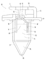
図1には、本実施形態におけるドアトリムの取り付け構造の概略を示す。図示されるように、ドアトリム1は、ドアパネル2の内側面2A上に配置され、ドアパネル2に対して複数のドアトリム用クリップ3及び10を介して固定されている。これら複数のクリップのうち、少なくとも1つのクリップに、本発明のドアトリム用クリップ10が採用される。本実施形態では、ドアトリム1の一方の側部の中央付近に配置されたクリップが、本発明のクリップ10となっている。なお、他のクリップ3としては、従来品のドアトリム用クリップが用いられている。
FIG. 1 shows an outline of a door trim mounting structure according to the present embodiment. As shown, the
図2から図5には、ドアトリム用クリップ10を示す。また、図6には、ドアトリム用クリップ10がドアトリム1及びドアパネル2に取り付けられた状態を示す。クリップ10は、例えば樹脂による一体成型で形成される部品であり、図示されるように、ドアトリム1に装着されるためのドアトリム装着部11と、ドアパネル2側に配置されるドアパネル装着部12と、ドアトリム装着部11とドアパネル装着部12の間に配置されたフランジ部13とを備えている。
2 to 5 show a
ドアトリム装着部11は、フランジ部13の下端付近から水平方向に延びる水平アーム部21と、この水平アーム部21から上方に向けて垂直方向に延びる垂直アーム部22とからなる断面L字型の部分である。なお、フランジ部13と垂直アーム部22の間には、補強用の連結部23が架け渡されている。このような構成により、ドアパネル装着部11は、ドアトリム1の取り付け部1A(図6参照)を垂直アーム部22とフランジ部13の間に挟持するようにして、ドアトリム1の取り付け部に対して装着固定されるようになっている。この場合、水平アーム部22が、クリップ10の下側に配置されるので、ドアトリム1の荷重を適切に受け止めることができるとともに、クリップ10の上下の向きを、確実に正しい配置とすることができる(後述する遮蔽壁32がクリップ10の上側に来るようにできる)。
The door
ドアパネル装着部12は、フランジ部13から、ドアトリム装着部11と反対側に延びた部分であり、このドアパネル装着部12がドアパネル2の取り付け穴2A内に挿入されることにより、クリップ10がドアパネル2に取り付けられる(図6参照)。図示されるように、ドアパネル装着部12は、両側の側壁31と、側壁31の上端付近に位置するように両側の側壁31の間に配置された遮蔽壁(上壁)32とを備えている。両側の側壁31は、フランジ部13から垂直に延びる基端側(フランジ部13側)の垂直面33と、垂直面33から先端側に連なって、互いの間隔を狭めるように傾いた傾斜面34とを備えている。
The door
各傾斜面34は、上辺及び下辺が先端に向かって間隔を狭めていく先細りの形状となっている。これにより、両側の傾斜面34の先端には、先端頂部35が形成されている。なお、この先端頂部35は、クリップ10をドアパネル2に装着するときに、ドアパネル2の取り付け穴(図示せず)に挿入される挿入端部となる。
Each
ドアパネル装着部12の遮蔽壁32は、フランジ部13から垂直に延びる基端側(フランジ部13側)の水平部36と、水平部36から先端側に連なって、先端側(先端頂部35側)に向かうにしたがって下方に向けて傾斜した傾斜部37とを備えている。傾斜部37は、先端頂部35の手前で終端しており、傾斜部37と両側傾斜面34の間には、上下方向に開口した開口部38が形成されている。なお、クリップ10の使用時には、クリップ10は、遮蔽壁32が上側に来るような配置で使用される。
The shielding
ドアパネル装着部12の下側(両側側壁31の下端側)は、壁部が設けられない開口39となっており、開口39の内側には、遮蔽壁32と両側の側壁31で囲まれた空間40が形成されている。これにより、空間40は、遮蔽壁32によってクリップ10の上方から遮蔽されている。また、ドアパネル装着部12の先端側において、空間40は、先端頂部35によって閉鎖された状態となっている。なお、ドアパネル装着部12の下側に開口39が形成されていることにより、この開口39を金型抜き用の穴として、後述する弾性係合片41を有するクリップ10を適切に樹脂成型で形成することができるようになっている。
The lower side of the door panel mounting portion 12 (the lower end side of the
各側壁31の垂直面33には、弾性係合片41が設けられている。弾性係合片41は、垂直面33の一部に切り欠き42を設けることにより形成されており、空間40内に向けて撓み得るようになっている。
An
各弾性係合片41のフランジ部13側の端部は、自由端である係合端部43となっており、各係合端部43は、フランジ部13の両側の側部に形成された係合片導入部である切り欠き部14内に入り込んで、フランジ部13の側方に配置されている。各係合端部43には、外側に向けて折れ曲がった係止爪44が形成されている。
The end of each elastic engaging
また、各弾性係合片41の外向き面には、係止部45が形成されている。係止部45は、係止爪44に対向した垂直段部46と、垂直段部46と反対側の勾配部47を備えている。勾配部47は、先端側(先端頂部35側)を向いた勾配面を形成している。
Further, a locking
なお、クリップ10の使用時には、フランジ部13のドアパネル装着部12側の面上には、ドアパネル装着部12を取り囲むように配置されるシール部材4が配置され、水密が図られるようになっている(図6参照)。
When the
このような構成により、ドアパネル2の取り付け穴2Aの縁部分が、シール部材4とともに、係止部45(垂直段部46)と係止爪43及びフランジ部13の間に挟持されることにより、クリップ10が、ドアパネル2の取り付け穴2Aに対して取り付けられるようになっている。したがって、クリップ10のドアパネル2への固定は、弾性係合片41を介して堅固に行われるので、ドアパネル2に他の車両が衝突した場合等でも、ドアトリム1は、クリップ10を介してドアパネル2に連結した状態となり、ドアパネル2から完全に脱落してしまうことを防止できる。
With such a configuration, the edge portion of the mounting
一方、クリップ10のドアパネル2からの取り外しに際しては、車室内側(ドアトリム1側)から弾性係合片41を操作して内側(空間40側)に向けて撓ませることにより、弾性係合片31とドアパネル2の取り付け部(取り付け穴2Aの縁部分)との係合を解除することができる。したがって、メンテナンス時には、ドアトリム1をドアパネル2から容易に完全に取り外すことができる。
On the other hand, when the
このように、クリップ10によれば、ドアトリム1をドアパネル2に堅固に取り付けることができるとともに、ドアパネル2からのドアトリム1の取り外し作業も問題なく容易に行うことができるが、それと同時に、車外側(ドアパネル2側)から車内側(ドアトリム1側)への雨水の侵入も適切に防止することができる。
As described above, according to the
詳しく説明すると、図5に示されるように、車外側からの雨水Wは、ドアパネル装着部12の遮蔽壁32上に零れ落ちると、水平部36から傾斜部37へと流れて行き、開口部38から排出される。すなわち、雨水Wは、クリップ10上に滞留することなく、車内側(ドアトリム1側)から遠い方に導かれていき、空間40の前方に向けて排出されるので、空間40内には入り込むことはない。したがって、フランジ部13に、弾性係合片41の係合端部43が入り込む切り欠き部14が形成されていたとしても、雨水Wが車内側に流れ込んでしまうことはなく、雨水Wの車内への侵入を適切に防止できる。
More specifically, as shown in FIG. 5, when the rainwater W from the outside of the vehicle spills onto the shielding
なお、上記実施形態において、ドアトリム1、ドアパネル2、ドアトリム装着部11、ドアパネル装着部12が、それぞれ、特許請求の範囲における第1の部材、第2の部材、第1の装着部、第2の装着部に相当する。
In the above embodiment, the
以上、本発明の実施形態について説明したが、本発明は、上記実施形態に限定されるものではなく、特許請求の範囲に記載された範囲において適宜の変更が可能である。例えば、上記実施形態では、ドアトリム1をドアパネル2に取り付けるドアトリム用クリップ10について説明してきたが、本発明のクリップは、このような形態に限られるものではなく、本発明は、任意の2つの部材を結合するためのクリップに広く適用できる。また、上記実施形態では、ドアトリム1をドアパネル2に取り付けるための複数のクリップのうちの1つを本発明のクリップ10としたが、本発明はこのような形態に限られるものではなく、複数のクリップのうちの2つ以上のクリップに、本発明のクリップを採用することも可能である。また、上記実施形態では、係合片導入部として、フランジ部13の側部に形成した切り欠き部14を用いたが、本発明はこのような形態に限られるものではなく、係合片導入部は、例えばフランジ部13に設けた穴であってもよい。
Although the embodiments of the present invention have been described above, the present invention is not limited to the above embodiments, and appropriate modifications can be made within the scope of the claims. For example, in the above embodiment, the
本発明は、車両においてドアパネルにドアトリムを適切に取り付けるために利用できる。 The present invention can be used to properly attach a door trim to a door panel in a vehicle.
1 ドアトリム
1A ドアトリムの取り付け部
2 ドアパネル
2A ドアパネルの取り付け穴
4 シール部材
3 ドアトリム用クリップ
10 ドアトリム用クリップ
11 ドアトリム装着部
12 ドアパネル装着部
13 フランジ部
14 フランジ部の切り欠き部
21 ドアトリム装着部の水平アーム部
22 ドアトリム装着部の垂直アーム部
23 ドアトリム装着部の連結部
31 ドアパネル装着部の側壁
32 ドアパネル装着部の遮蔽壁
33 側壁の垂直面
34 側壁の傾斜面
35 先端頂部
36 遮蔽壁の水平部
37 遮蔽壁の傾斜部
38 開口部
39 開口
40 空間
41 弾性係合片
42 切り欠き
43 弾性係合片の係合端部
44 係止爪
45 係止部
46 垂直段部
47 勾配部
1
Claims (5)
前記第1の部材に装着される第1の装着部と、
前記第2の部材に装着される第2の装着部と、
前記第1の装着部と前記第2の装着部の間に設けられたフランジ部とを備え、
前記第2の装着部は、弾性係合片が切り欠きにより形成されている両側の側壁と、前記両側の側壁の間に設けられて前記クリップの使用時において前記両側の側壁の間の空間を上側から遮蔽する遮蔽壁とを備え、
前記弾性係合片の係合端部が、前記第1の装着部側に延びており、
前記遮蔽壁は、前記フランジ部側に設けられた平面部と、前記フランジ部と反対側に設けられた傾斜部とを備え、前記傾斜部は、前記フランジ部と反対側に向かうにしたがって下方に傾斜しており、
前記平面部は、前記遮蔽壁に零れ落ちてくる雨水を前記傾斜部へと流すように、前記両側の側壁の間において前記遮蔽壁のフランジ部から延びる基端部が水平部とされているクリップ。 In the clip for attaching the first member to the second member,
A first mounting portion mounted on the first member and
A second mounting portion mounted on the second member and
A flange portion provided between the first mounting portion and the second mounting portion is provided.
The second mounting portion is provided between the side walls on both sides in which the elastic engaging piece is formed by a notch, and the space between the side walls on both sides when the clip is used. Equipped with a shielding wall that shields from above,
The engaging end portion of the elastic engaging piece extends toward the first mounting portion side.
The shielding wall includes a flat surface portion provided on the flange portion side and an inclined portion provided on the side opposite to the flange portion, and the inclined portion decreases downward toward the side opposite to the flange portion. It is tilted
The flat surface portion is a clip whose base end portion extending from the flange portion of the shielding wall is a horizontal portion between the side walls on both sides so that rainwater spilling onto the shielding wall flows to the inclined portion. ..
前記第1の部材に装着される第1の装着部と、
前記第2の部材に装着される第2の装着部と、
前記第1の装着部と前記第2の装着部の間に設けられたフランジ部とを備え、
前記第2の装着部は、弾性係合片が切り欠きにより形成されている両側の側壁と、前記両側の側壁の間に設けられて前記クリップの使用時において前記両側の側壁の間の空間を上側から遮蔽する遮蔽壁とを備え、
前記弾性係合片の係合端部が、前記第1の装着部側に延びており、
前記フランジ部に、前記第1の装着部側に連通する係合片導入部を備え、前記弾性係合片の係合端部が、前記係合片導入部内に入り込むようにしたクリップ。 In the clip for attaching the first member to the second member,
A first mounting portion mounted on the first member and
A second mounting portion mounted on the second member and
A flange portion provided between the first mounting portion and the second mounting portion is provided.
The second mounting portion is provided between the side walls on both sides in which the elastic engaging piece is formed by a notch, and the space between the side walls on both sides when the clip is used. Equipped with a shielding wall that shields from above,
The engaging end portion of the elastic engaging piece extends toward the first mounting portion side.
A clip in which the flange portion is provided with an engaging piece introduction portion communicating with the first mounting portion side, and the engaging end portion of the elastic engaging piece is inserted into the engaging piece introduction portion.
前記ドアトリムを固定するために車室内側から前記ドアパネルに対して略水平方向に挿入固定されるドアトリム用クリップを備え、
前記ドアトリム用クリップにおける前記ドアパネルに固定挿入される部分は、両側の側壁と、前記両側の側壁の間に設けられた遮蔽壁とを備え、
前記両側の側壁の各々は、前記車室内側に向けて延びる係合端部を有する弾性係合片を備え、
前記遮蔽壁は、前記弾性係合片よりも上方に配置されて、前記ドアトリム用クリップの前記ドアパネルに挿入される部分を上側から遮蔽するようになっているドアトリムの取り付け構造。 Attaching the door trim to the door panel In the door trim mounting structure,
A clip for door trim that is inserted and fixed substantially horizontally to the door panel from the vehicle interior side to fix the door trim is provided.
A portion of the door trim clip that is fixedly inserted into the door panel includes side walls on both sides and shielding walls provided between the side walls on both sides.
Each of the side walls on both sides comprises an elastic engagement piece having an engagement end extending towards the passenger compartment side.
A door trim mounting structure in which the shielding wall is arranged above the elastic engaging piece so as to shield a portion of the door trim clip to be inserted into the door panel from above.
前記水平アーム部は、前記垂直アーム部の下端側に位置している請求項4に記載のドアトリムの取り付け構造。 The portion of the door trim clip attached to the door trim has an L-shaped cross section including a horizontal arm portion extending in the horizontal direction and a vertical arm portion extending in the vertical direction from the horizontal arm portion.
The door trim mounting structure according to claim 4, wherein the horizontal arm portion is located on the lower end side of the vertical arm portion.
Priority Applications (4)
| Application Number | Priority Date | Filing Date | Title |
|---|---|---|---|
| JP2017001571A JP6817818B2 (en) | 2017-01-10 | 2017-01-10 | Clip and door trim mounting structure |
| CN201810010040.2A CN108284801B (en) | 2017-01-10 | 2018-01-05 | Mounting structure of clip and door trim |
| MX2018000423A MX395452B (en) | 2017-01-10 | 2018-01-10 | CLIP AND MOUNTING STRUCTURE FOR DOOR LID. |
| US15/866,867 US10471909B2 (en) | 2017-01-10 | 2018-01-10 | Clip and mounting structure of door trim |
Applications Claiming Priority (1)
| Application Number | Priority Date | Filing Date | Title |
|---|---|---|---|
| JP2017001571A JP6817818B2 (en) | 2017-01-10 | 2017-01-10 | Clip and door trim mounting structure |
Publications (2)
| Publication Number | Publication Date |
|---|---|
| JP2018112207A JP2018112207A (en) | 2018-07-19 |
| JP6817818B2 true JP6817818B2 (en) | 2021-01-20 |
Family
ID=62782208
Family Applications (1)
| Application Number | Title | Priority Date | Filing Date |
|---|---|---|---|
| JP2017001571A Active JP6817818B2 (en) | 2017-01-10 | 2017-01-10 | Clip and door trim mounting structure |
Country Status (4)
| Country | Link |
|---|---|
| US (1) | US10471909B2 (en) |
| JP (1) | JP6817818B2 (en) |
| CN (1) | CN108284801B (en) |
| MX (1) | MX395452B (en) |
Families Citing this family (10)
| Publication number | Priority date | Publication date | Assignee | Title |
|---|---|---|---|---|
| EP3670938A1 (en) * | 2018-12-21 | 2020-06-24 | A. Raymond et Cie | Toolless slot fastener |
| US12092140B2 (en) | 2020-01-27 | 2024-09-17 | Illinois Tool Works Inc. | Fastening clip |
| US12534028B2 (en) | 2020-03-03 | 2026-01-27 | Illinois Tool Works Inc. | Stamped metal trim retainer |
| US11519442B2 (en) * | 2020-05-11 | 2022-12-06 | Illinois Tool Works Inc. | Blind assembly fastener system |
| DE102021111776A1 (en) | 2020-05-11 | 2021-11-11 | Illinois Tool Works Inc. | BLIND MOUNTING FASTENING SYSTEM |
| US11542975B2 (en) | 2020-05-11 | 2023-01-03 | Illinois Tool Works Inc. | Blind assembly fastener system |
| US11815124B2 (en) * | 2021-03-05 | 2023-11-14 | Illinois Tool Works Inc. | Fastener assembly |
| US11994160B2 (en) | 2022-04-20 | 2024-05-28 | Illinois Tool Works Inc. | Fastener |
| USD1065996S1 (en) | 2022-07-08 | 2025-03-11 | Illinois Tool Works Inc. | Fastener |
| USD1049841S1 (en) | 2022-08-24 | 2024-11-05 | Illinois Tool Works Inc. | Fastener |
Family Cites Families (19)
| Publication number | Priority date | Publication date | Assignee | Title |
|---|---|---|---|---|
| JPS59106710A (en) | 1982-12-08 | 1984-06-20 | 日産自動車株式会社 | Trim holder for car |
| JP2006298131A (en) * | 2005-04-20 | 2006-11-02 | Piolax Inc | Coupling structure between automobile interior component and vehicle body panel |
| USD541644S1 (en) * | 2005-10-21 | 2007-05-01 | Piolax Inc. | Snap device for airbag container |
| DE102006017878A1 (en) * | 2006-04-13 | 2007-10-25 | Newfrey Llc, Newark | mounting clip |
| DE202008010262U1 (en) * | 2008-04-18 | 2008-10-16 | Trw Automotive Electronics & Components Gmbh | Connection assembly for mounting an add-on element on a carrier element |
| US7757997B2 (en) * | 2008-07-31 | 2010-07-20 | Delphi Technologies, Inc. | Clip for fastening an article to a panel having a self-expanding clip head |
| FR2944569B1 (en) * | 2009-04-20 | 2011-04-01 | Raymond A & Cie | RIB WING ATTACHMENT |
| DE202009011986U1 (en) * | 2009-08-28 | 2009-12-10 | Illinois Tool Works Inc., Glenview | Device for connecting two components |
| JP5451366B2 (en) * | 2009-12-24 | 2014-03-26 | 株式会社ニフコ | clip |
| WO2011119411A1 (en) * | 2010-03-24 | 2011-09-29 | Illinois Tool Works Inc. | Serviceable snap-in fastener |
| CN103079892B (en) * | 2010-09-07 | 2015-06-03 | 丰田自动车株式会社 | Trim Mounting Device |
| JP5742691B2 (en) * | 2011-11-30 | 2015-07-01 | トヨタ自動車株式会社 | Tether clip and garnish attachment device having the same |
| JP6054192B2 (en) * | 2013-01-31 | 2016-12-27 | 大和化成工業株式会社 | Clip mounting structure |
| JP6128233B2 (en) * | 2013-11-29 | 2017-05-24 | トヨタ自動車株式会社 | Clip and pillar garnish mounting structure |
| JP5888615B2 (en) * | 2013-12-17 | 2016-03-22 | ポップリベット・ファスナー株式会社 | Mounting member mounting structure |
| JP5895948B2 (en) * | 2014-01-09 | 2016-03-30 | トヨタ自動車株式会社 | Clip and pillar garnish mounting structure |
| JP5907190B2 (en) * | 2014-01-29 | 2016-04-26 | トヨタ自動車株式会社 | Pillar garnish mounting structure and tether clip |
| FR3016938B1 (en) * | 2014-01-30 | 2016-02-26 | Illinois Tool Works | ATTACHMENT FOR ATTACHING A PANEL TO A SUPPORT |
| JP6328476B2 (en) * | 2014-04-16 | 2018-05-23 | 大和化成工業株式会社 | clip |
-
2017
- 2017-01-10 JP JP2017001571A patent/JP6817818B2/en active Active
-
2018
- 2018-01-05 CN CN201810010040.2A patent/CN108284801B/en active Active
- 2018-01-10 US US15/866,867 patent/US10471909B2/en active Active
- 2018-01-10 MX MX2018000423A patent/MX395452B/en unknown
Also Published As
| Publication number | Publication date |
|---|---|
| CN108284801A (en) | 2018-07-17 |
| JP2018112207A (en) | 2018-07-19 |
| US20180194301A1 (en) | 2018-07-12 |
| US10471909B2 (en) | 2019-11-12 |
| MX2018000423A (en) | 2018-11-09 |
| CN108284801B (en) | 2021-08-06 |
| MX395452B (en) | 2025-03-25 |
Similar Documents
| Publication | Publication Date | Title |
|---|---|---|
| JP6817818B2 (en) | Clip and door trim mounting structure | |
| US8979166B2 (en) | Fender panel mounting structure for vehicle | |
| US10793100B2 (en) | Automobile cowl grille structure | |
| JP2020104569A (en) | Cowl top structure | |
| US20160001739A1 (en) | Vehicular interior member assembly and vehicular interior part | |
| JP5314305B2 (en) | Car front pillar trim mounting structure | |
| CN114514145A (en) | Camera hood mounting structure | |
| JP6545730B2 (en) | Mounting structure of door frame molding | |
| KR102552166B1 (en) | Structure for B-pillar without Inner panel | |
| CN103204112B (en) | The installation constitution of inner-decoration component and instrument panel structure | |
| JP4940473B2 (en) | Scuff plate mounting structure | |
| JP6120442B2 (en) | Cowl top cover | |
| CN108202766B (en) | Front vehicle body structure of vehicle | |
| JP2019055615A (en) | Center cluster panel mounting structure | |
| JP3690153B2 (en) | Connecting structure by fitting claws of automobile interior parts | |
| JP5429598B2 (en) | Interior part mating part structure | |
| CN114906225B (en) | Front shroud device | |
| KR100811952B1 (en) | Mounting structure of car door scuff trim and door scuff trim | |
| CN108454529B (en) | Interior trim part for vehicle | |
| JP2018103678A (en) | Cowl cover device | |
| JP4591209B2 (en) | Seal member mounting structure | |
| KR0126601Y1 (en) | Attaching structure of front pillar trim | |
| JP2015189327A (en) | Attachment structure of meter cluster | |
| JP2013078993A (en) | Vehicle door structure | |
| JP2019182373A (en) | Roof rack attachment structure |
Legal Events
| Date | Code | Title | Description |
|---|---|---|---|
| A621 | Written request for application examination |
Free format text: JAPANESE INTERMEDIATE CODE: A621 Effective date: 20190625 |
|
| A977 | Report on retrieval |
Free format text: JAPANESE INTERMEDIATE CODE: A971007 Effective date: 20200526 |
|
| A131 | Notification of reasons for refusal |
Free format text: JAPANESE INTERMEDIATE CODE: A131 Effective date: 20200703 |
|
| A521 | Request for written amendment filed |
Free format text: JAPANESE INTERMEDIATE CODE: A523 Effective date: 20200828 |
|
| A131 | Notification of reasons for refusal |
Free format text: JAPANESE INTERMEDIATE CODE: A131 Effective date: 20201106 |
|
| A521 | Request for written amendment filed |
Free format text: JAPANESE INTERMEDIATE CODE: A523 Effective date: 20201127 |
|
| TRDD | Decision of grant or rejection written | ||
| A01 | Written decision to grant a patent or to grant a registration (utility model) |
Free format text: JAPANESE INTERMEDIATE CODE: A01 Effective date: 20201218 |
|
| A61 | First payment of annual fees (during grant procedure) |
Free format text: JAPANESE INTERMEDIATE CODE: A61 Effective date: 20201225 |
|
| R150 | Certificate of patent or registration of utility model |
Ref document number: 6817818 Country of ref document: JP Free format text: JAPANESE INTERMEDIATE CODE: R150 |
|
| R250 | Receipt of annual fees |
Free format text: JAPANESE INTERMEDIATE CODE: R250 |
|
| R250 | Receipt of annual fees |
Free format text: JAPANESE INTERMEDIATE CODE: R250 |
|
| R250 | Receipt of annual fees |
Free format text: JAPANESE INTERMEDIATE CODE: R250 |