JP6772292B2 - Laminated molded product and its manufacturing method - Google Patents
Laminated molded product and its manufacturing method Download PDFInfo
- Publication number
- JP6772292B2 JP6772292B2 JP2018552502A JP2018552502A JP6772292B2 JP 6772292 B2 JP6772292 B2 JP 6772292B2 JP 2018552502 A JP2018552502 A JP 2018552502A JP 2018552502 A JP2018552502 A JP 2018552502A JP 6772292 B2 JP6772292 B2 JP 6772292B2
- Authority
- JP
- Japan
- Prior art keywords
- material layer
- cushioning material
- layer
- laminated molded
- adhesive
- Prior art date
- Legal status (The legal status is an assumption and is not a legal conclusion. Google has not performed a legal analysis and makes no representation as to the accuracy of the status listed.)
- Active
Links
- 238000004519 manufacturing process Methods 0.000 title claims description 17
- 239000010410 layer Substances 0.000 claims description 253
- 239000000463 material Substances 0.000 claims description 252
- 239000012790 adhesive layer Substances 0.000 claims description 93
- 239000000853 adhesive Substances 0.000 claims description 26
- 230000001070 adhesive effect Effects 0.000 claims description 26
- 238000003825 pressing Methods 0.000 claims description 17
- 239000004745 nonwoven fabric Substances 0.000 claims description 12
- 210000002615 epidermis Anatomy 0.000 claims description 5
- 238000002407 reforming Methods 0.000 claims description 5
- 238000012360 testing method Methods 0.000 description 37
- 238000000034 method Methods 0.000 description 35
- 238000013461 design Methods 0.000 description 30
- JOYRKODLDBILNP-UHFFFAOYSA-N Ethyl urethane Chemical compound CCOC(N)=O JOYRKODLDBILNP-UHFFFAOYSA-N 0.000 description 24
- 239000006260 foam Substances 0.000 description 21
- 230000008569 process Effects 0.000 description 21
- 238000012545 processing Methods 0.000 description 13
- 238000003466 welding Methods 0.000 description 12
- 239000010985 leather Substances 0.000 description 11
- 229910003460 diamond Inorganic materials 0.000 description 10
- 239000010432 diamond Substances 0.000 description 10
- 238000000926 separation method Methods 0.000 description 10
- 230000007246 mechanism Effects 0.000 description 8
- 239000002344 surface layer Substances 0.000 description 8
- 230000006866 deterioration Effects 0.000 description 7
- 238000009958 sewing Methods 0.000 description 7
- 239000002649 leather substitute Substances 0.000 description 5
- 229920001169 thermoplastic Polymers 0.000 description 5
- 239000004416 thermosoftening plastic Substances 0.000 description 5
- 239000011800 void material Substances 0.000 description 5
- 230000000052 comparative effect Effects 0.000 description 4
- 238000007796 conventional method Methods 0.000 description 4
- 238000005520 cutting process Methods 0.000 description 4
- 239000000203 mixture Substances 0.000 description 3
- 238000003672 processing method Methods 0.000 description 3
- 210000003491 skin Anatomy 0.000 description 3
- 229920000742 Cotton Polymers 0.000 description 2
- 238000010586 diagram Methods 0.000 description 2
- 230000000694 effects Effects 0.000 description 2
- 230000002708 enhancing effect Effects 0.000 description 2
- 238000002474 experimental method Methods 0.000 description 2
- 239000004744 fabric Substances 0.000 description 2
- 238000002347 injection Methods 0.000 description 2
- 239000007924 injection Substances 0.000 description 2
- 238000000465 moulding Methods 0.000 description 2
- 230000037368 penetrate the skin Effects 0.000 description 2
- VYZAMTAEIAYCRO-UHFFFAOYSA-N Chromium Chemical compound [Cr] VYZAMTAEIAYCRO-UHFFFAOYSA-N 0.000 description 1
- 238000007792 addition Methods 0.000 description 1
- 238000004378 air conditioning Methods 0.000 description 1
- 230000008859 change Effects 0.000 description 1
- 238000001816 cooling Methods 0.000 description 1
- 238000005034 decoration Methods 0.000 description 1
- 238000010097 foam moulding Methods 0.000 description 1
- 238000005187 foaming Methods 0.000 description 1
- 238000010438 heat treatment Methods 0.000 description 1
- 230000001771 impaired effect Effects 0.000 description 1
- 230000006872 improvement Effects 0.000 description 1
- 238000010030 laminating Methods 0.000 description 1
- 239000000123 paper Substances 0.000 description 1
- 230000035699 permeability Effects 0.000 description 1
- 239000004800 polyvinyl chloride Substances 0.000 description 1
- 230000000007 visual effect Effects 0.000 description 1
- 239000002759 woven fabric Substances 0.000 description 1
Images





Classifications
-
- B—PERFORMING OPERATIONS; TRANSPORTING
- B32—LAYERED PRODUCTS
- B32B—LAYERED PRODUCTS, i.e. PRODUCTS BUILT-UP OF STRATA OF FLAT OR NON-FLAT, e.g. CELLULAR OR HONEYCOMB, FORM
- B32B3/00—Layered products comprising a layer with external or internal discontinuities or unevennesses, or a layer of non-planar shape; Layered products comprising a layer having particular features of form
- B32B3/26—Layered products comprising a layer with external or internal discontinuities or unevennesses, or a layer of non-planar shape; Layered products comprising a layer having particular features of form characterised by a particular shape of the outline of the cross-section of a continuous layer; characterised by a layer with cavities or internal voids ; characterised by an apertured layer
- B32B3/263—Layered products comprising a layer with external or internal discontinuities or unevennesses, or a layer of non-planar shape; Layered products comprising a layer having particular features of form characterised by a particular shape of the outline of the cross-section of a continuous layer; characterised by a layer with cavities or internal voids ; characterised by an apertured layer characterised by a layer having non-uniform thickness
-
- B—PERFORMING OPERATIONS; TRANSPORTING
- B32—LAYERED PRODUCTS
- B32B—LAYERED PRODUCTS, i.e. PRODUCTS BUILT-UP OF STRATA OF FLAT OR NON-FLAT, e.g. CELLULAR OR HONEYCOMB, FORM
- B32B27/00—Layered products comprising a layer of synthetic resin
- B32B27/06—Layered products comprising a layer of synthetic resin as the main or only constituent of a layer, which is next to another layer of the same or of a different material
- B32B27/065—Layered products comprising a layer of synthetic resin as the main or only constituent of a layer, which is next to another layer of the same or of a different material of foam
-
- B—PERFORMING OPERATIONS; TRANSPORTING
- B32—LAYERED PRODUCTS
- B32B—LAYERED PRODUCTS, i.e. PRODUCTS BUILT-UP OF STRATA OF FLAT OR NON-FLAT, e.g. CELLULAR OR HONEYCOMB, FORM
- B32B27/00—Layered products comprising a layer of synthetic resin
- B32B27/12—Layered products comprising a layer of synthetic resin next to a fibrous or filamentary layer
-
- B—PERFORMING OPERATIONS; TRANSPORTING
- B32—LAYERED PRODUCTS
- B32B—LAYERED PRODUCTS, i.e. PRODUCTS BUILT-UP OF STRATA OF FLAT OR NON-FLAT, e.g. CELLULAR OR HONEYCOMB, FORM
- B32B3/00—Layered products comprising a layer with external or internal discontinuities or unevennesses, or a layer of non-planar shape; Layered products comprising a layer having particular features of form
- B32B3/26—Layered products comprising a layer with external or internal discontinuities or unevennesses, or a layer of non-planar shape; Layered products comprising a layer having particular features of form characterised by a particular shape of the outline of the cross-section of a continuous layer; characterised by a layer with cavities or internal voids ; characterised by an apertured layer
-
- B—PERFORMING OPERATIONS; TRANSPORTING
- B32—LAYERED PRODUCTS
- B32B—LAYERED PRODUCTS, i.e. PRODUCTS BUILT-UP OF STRATA OF FLAT OR NON-FLAT, e.g. CELLULAR OR HONEYCOMB, FORM
- B32B3/00—Layered products comprising a layer with external or internal discontinuities or unevennesses, or a layer of non-planar shape; Layered products comprising a layer having particular features of form
- B32B3/26—Layered products comprising a layer with external or internal discontinuities or unevennesses, or a layer of non-planar shape; Layered products comprising a layer having particular features of form characterised by a particular shape of the outline of the cross-section of a continuous layer; characterised by a layer with cavities or internal voids ; characterised by an apertured layer
- B32B3/28—Layered products comprising a layer with external or internal discontinuities or unevennesses, or a layer of non-planar shape; Layered products comprising a layer having particular features of form characterised by a particular shape of the outline of the cross-section of a continuous layer; characterised by a layer with cavities or internal voids ; characterised by an apertured layer characterised by a layer comprising a deformed thin sheet, i.e. the layer having its entire thickness deformed out of the plane, e.g. corrugated, crumpled
-
- B—PERFORMING OPERATIONS; TRANSPORTING
- B32—LAYERED PRODUCTS
- B32B—LAYERED PRODUCTS, i.e. PRODUCTS BUILT-UP OF STRATA OF FLAT OR NON-FLAT, e.g. CELLULAR OR HONEYCOMB, FORM
- B32B3/00—Layered products comprising a layer with external or internal discontinuities or unevennesses, or a layer of non-planar shape; Layered products comprising a layer having particular features of form
- B32B3/26—Layered products comprising a layer with external or internal discontinuities or unevennesses, or a layer of non-planar shape; Layered products comprising a layer having particular features of form characterised by a particular shape of the outline of the cross-section of a continuous layer; characterised by a layer with cavities or internal voids ; characterised by an apertured layer
- B32B3/30—Layered products comprising a layer with external or internal discontinuities or unevennesses, or a layer of non-planar shape; Layered products comprising a layer having particular features of form characterised by a particular shape of the outline of the cross-section of a continuous layer; characterised by a layer with cavities or internal voids ; characterised by an apertured layer characterised by a layer formed with recesses or projections, e.g. hollows, grooves, protuberances, ribs
-
- B—PERFORMING OPERATIONS; TRANSPORTING
- B32—LAYERED PRODUCTS
- B32B—LAYERED PRODUCTS, i.e. PRODUCTS BUILT-UP OF STRATA OF FLAT OR NON-FLAT, e.g. CELLULAR OR HONEYCOMB, FORM
- B32B5/00—Layered products characterised by the non- homogeneity or physical structure, i.e. comprising a fibrous, filamentary, particulate or foam layer; Layered products characterised by having a layer differing constitutionally or physically in different parts
- B32B5/02—Layered products characterised by the non- homogeneity or physical structure, i.e. comprising a fibrous, filamentary, particulate or foam layer; Layered products characterised by having a layer differing constitutionally or physically in different parts characterised by structural features of a fibrous or filamentary layer
- B32B5/022—Non-woven fabric
-
- B—PERFORMING OPERATIONS; TRANSPORTING
- B32—LAYERED PRODUCTS
- B32B—LAYERED PRODUCTS, i.e. PRODUCTS BUILT-UP OF STRATA OF FLAT OR NON-FLAT, e.g. CELLULAR OR HONEYCOMB, FORM
- B32B5/00—Layered products characterised by the non- homogeneity or physical structure, i.e. comprising a fibrous, filamentary, particulate or foam layer; Layered products characterised by having a layer differing constitutionally or physically in different parts
- B32B5/02—Layered products characterised by the non- homogeneity or physical structure, i.e. comprising a fibrous, filamentary, particulate or foam layer; Layered products characterised by having a layer differing constitutionally or physically in different parts characterised by structural features of a fibrous or filamentary layer
- B32B5/028—Net structure, e.g. spaced apart filaments bonded at the crossing points
-
- B—PERFORMING OPERATIONS; TRANSPORTING
- B32—LAYERED PRODUCTS
- B32B—LAYERED PRODUCTS, i.e. PRODUCTS BUILT-UP OF STRATA OF FLAT OR NON-FLAT, e.g. CELLULAR OR HONEYCOMB, FORM
- B32B5/00—Layered products characterised by the non- homogeneity or physical structure, i.e. comprising a fibrous, filamentary, particulate or foam layer; Layered products characterised by having a layer differing constitutionally or physically in different parts
- B32B5/02—Layered products characterised by the non- homogeneity or physical structure, i.e. comprising a fibrous, filamentary, particulate or foam layer; Layered products characterised by having a layer differing constitutionally or physically in different parts characterised by structural features of a fibrous or filamentary layer
- B32B5/06—Layered products characterised by the non- homogeneity or physical structure, i.e. comprising a fibrous, filamentary, particulate or foam layer; Layered products characterised by having a layer differing constitutionally or physically in different parts characterised by structural features of a fibrous or filamentary layer characterised by a fibrous or filamentary layer mechanically connected, e.g. by needling to another layer, e.g. of fibres, of paper
-
- B—PERFORMING OPERATIONS; TRANSPORTING
- B32—LAYERED PRODUCTS
- B32B—LAYERED PRODUCTS, i.e. PRODUCTS BUILT-UP OF STRATA OF FLAT OR NON-FLAT, e.g. CELLULAR OR HONEYCOMB, FORM
- B32B5/00—Layered products characterised by the non- homogeneity or physical structure, i.e. comprising a fibrous, filamentary, particulate or foam layer; Layered products characterised by having a layer differing constitutionally or physically in different parts
- B32B5/18—Layered products characterised by the non- homogeneity or physical structure, i.e. comprising a fibrous, filamentary, particulate or foam layer; Layered products characterised by having a layer differing constitutionally or physically in different parts characterised by features of a layer of foamed material
-
- B—PERFORMING OPERATIONS; TRANSPORTING
- B32—LAYERED PRODUCTS
- B32B—LAYERED PRODUCTS, i.e. PRODUCTS BUILT-UP OF STRATA OF FLAT OR NON-FLAT, e.g. CELLULAR OR HONEYCOMB, FORM
- B32B7/00—Layered products characterised by the relation between layers; Layered products characterised by the relative orientation of features between layers, or by the relative values of a measurable parameter between layers, i.e. products comprising layers having different physical, chemical or physicochemical properties; Layered products characterised by the interconnection of layers
- B32B7/04—Interconnection of layers
- B32B7/05—Interconnection of layers the layers not being connected over the whole surface, e.g. discontinuous connection or patterned connection
-
- B—PERFORMING OPERATIONS; TRANSPORTING
- B32—LAYERED PRODUCTS
- B32B—LAYERED PRODUCTS, i.e. PRODUCTS BUILT-UP OF STRATA OF FLAT OR NON-FLAT, e.g. CELLULAR OR HONEYCOMB, FORM
- B32B7/00—Layered products characterised by the relation between layers; Layered products characterised by the relative orientation of features between layers, or by the relative values of a measurable parameter between layers, i.e. products comprising layers having different physical, chemical or physicochemical properties; Layered products characterised by the interconnection of layers
- B32B7/04—Interconnection of layers
- B32B7/08—Interconnection of layers by mechanical means
- B32B7/09—Interconnection of layers by mechanical means by stitching, needling or sewing
-
- B—PERFORMING OPERATIONS; TRANSPORTING
- B32—LAYERED PRODUCTS
- B32B—LAYERED PRODUCTS, i.e. PRODUCTS BUILT-UP OF STRATA OF FLAT OR NON-FLAT, e.g. CELLULAR OR HONEYCOMB, FORM
- B32B7/00—Layered products characterised by the relation between layers; Layered products characterised by the relative orientation of features between layers, or by the relative values of a measurable parameter between layers, i.e. products comprising layers having different physical, chemical or physicochemical properties; Layered products characterised by the interconnection of layers
- B32B7/04—Interconnection of layers
- B32B7/12—Interconnection of layers using interposed adhesives or interposed materials with bonding properties
-
- B—PERFORMING OPERATIONS; TRANSPORTING
- B32—LAYERED PRODUCTS
- B32B—LAYERED PRODUCTS, i.e. PRODUCTS BUILT-UP OF STRATA OF FLAT OR NON-FLAT, e.g. CELLULAR OR HONEYCOMB, FORM
- B32B9/00—Layered products comprising a layer of a particular substance not covered by groups B32B11/00 - B32B29/00
- B32B9/02—Layered products comprising a layer of a particular substance not covered by groups B32B11/00 - B32B29/00 comprising animal or vegetable substances, e.g. cork, bamboo, starch
- B32B9/025—Layered products comprising a layer of a particular substance not covered by groups B32B11/00 - B32B29/00 comprising animal or vegetable substances, e.g. cork, bamboo, starch comprising leather
-
- B—PERFORMING OPERATIONS; TRANSPORTING
- B32—LAYERED PRODUCTS
- B32B—LAYERED PRODUCTS, i.e. PRODUCTS BUILT-UP OF STRATA OF FLAT OR NON-FLAT, e.g. CELLULAR OR HONEYCOMB, FORM
- B32B9/00—Layered products comprising a layer of a particular substance not covered by groups B32B11/00 - B32B29/00
- B32B9/04—Layered products comprising a layer of a particular substance not covered by groups B32B11/00 - B32B29/00 comprising such particular substance as the main or only constituent of a layer, which is next to another layer of the same or of a different material
- B32B9/045—Layered products comprising a layer of a particular substance not covered by groups B32B11/00 - B32B29/00 comprising such particular substance as the main or only constituent of a layer, which is next to another layer of the same or of a different material of synthetic resin
-
- B—PERFORMING OPERATIONS; TRANSPORTING
- B60—VEHICLES IN GENERAL
- B60N—SEATS SPECIALLY ADAPTED FOR VEHICLES; VEHICLE PASSENGER ACCOMMODATION NOT OTHERWISE PROVIDED FOR
- B60N2/00—Seats specially adapted for vehicles; Arrangement or mounting of seats in vehicles
- B60N2/58—Seat coverings
-
- B—PERFORMING OPERATIONS; TRANSPORTING
- B68—SADDLERY; UPHOLSTERY
- B68G—METHODS, EQUIPMENT, OR MACHINES FOR USE IN UPHOLSTERING; UPHOLSTERY NOT OTHERWISE PROVIDED FOR
- B68G7/00—Making upholstery
- B68G7/08—Quilting; Elements therefor
-
- B—PERFORMING OPERATIONS; TRANSPORTING
- B68—SADDLERY; UPHOLSTERY
- B68G—METHODS, EQUIPMENT, OR MACHINES FOR USE IN UPHOLSTERING; UPHOLSTERY NOT OTHERWISE PROVIDED FOR
- B68G7/00—Making upholstery
- B68G7/12—Other elements specially adapted for fastening, fixing, or finishing, in upholstery work
-
- B—PERFORMING OPERATIONS; TRANSPORTING
- B32—LAYERED PRODUCTS
- B32B—LAYERED PRODUCTS, i.e. PRODUCTS BUILT-UP OF STRATA OF FLAT OR NON-FLAT, e.g. CELLULAR OR HONEYCOMB, FORM
- B32B2250/00—Layers arrangement
- B32B2250/03—3 layers
-
- B—PERFORMING OPERATIONS; TRANSPORTING
- B32—LAYERED PRODUCTS
- B32B—LAYERED PRODUCTS, i.e. PRODUCTS BUILT-UP OF STRATA OF FLAT OR NON-FLAT, e.g. CELLULAR OR HONEYCOMB, FORM
- B32B2250/00—Layers arrangement
- B32B2250/04—4 layers
-
- B—PERFORMING OPERATIONS; TRANSPORTING
- B32—LAYERED PRODUCTS
- B32B—LAYERED PRODUCTS, i.e. PRODUCTS BUILT-UP OF STRATA OF FLAT OR NON-FLAT, e.g. CELLULAR OR HONEYCOMB, FORM
- B32B2250/00—Layers arrangement
- B32B2250/05—5 or more layers
-
- B—PERFORMING OPERATIONS; TRANSPORTING
- B32—LAYERED PRODUCTS
- B32B—LAYERED PRODUCTS, i.e. PRODUCTS BUILT-UP OF STRATA OF FLAT OR NON-FLAT, e.g. CELLULAR OR HONEYCOMB, FORM
- B32B2266/00—Composition of foam
- B32B2266/02—Organic
- B32B2266/0214—Materials belonging to B32B27/00
- B32B2266/0278—Polyurethane
-
- B—PERFORMING OPERATIONS; TRANSPORTING
- B32—LAYERED PRODUCTS
- B32B—LAYERED PRODUCTS, i.e. PRODUCTS BUILT-UP OF STRATA OF FLAT OR NON-FLAT, e.g. CELLULAR OR HONEYCOMB, FORM
- B32B2307/00—Properties of the layers or laminate
- B32B2307/70—Other properties
- B32B2307/732—Dimensional properties
-
- B—PERFORMING OPERATIONS; TRANSPORTING
- B32—LAYERED PRODUCTS
- B32B—LAYERED PRODUCTS, i.e. PRODUCTS BUILT-UP OF STRATA OF FLAT OR NON-FLAT, e.g. CELLULAR OR HONEYCOMB, FORM
- B32B2451/00—Decorative or ornamental articles
-
- B—PERFORMING OPERATIONS; TRANSPORTING
- B32—LAYERED PRODUCTS
- B32B—LAYERED PRODUCTS, i.e. PRODUCTS BUILT-UP OF STRATA OF FLAT OR NON-FLAT, e.g. CELLULAR OR HONEYCOMB, FORM
- B32B2601/00—Upholstery
-
- B—PERFORMING OPERATIONS; TRANSPORTING
- B32—LAYERED PRODUCTS
- B32B—LAYERED PRODUCTS, i.e. PRODUCTS BUILT-UP OF STRATA OF FLAT OR NON-FLAT, e.g. CELLULAR OR HONEYCOMB, FORM
- B32B2605/00—Vehicles
- B32B2605/003—Interior finishings
-
- B—PERFORMING OPERATIONS; TRANSPORTING
- B32—LAYERED PRODUCTS
- B32B—LAYERED PRODUCTS, i.e. PRODUCTS BUILT-UP OF STRATA OF FLAT OR NON-FLAT, e.g. CELLULAR OR HONEYCOMB, FORM
- B32B2605/00—Vehicles
- B32B2605/08—Cars
-
- B—PERFORMING OPERATIONS; TRANSPORTING
- B60—VEHICLES IN GENERAL
- B60N—SEATS SPECIALLY ADAPTED FOR VEHICLES; VEHICLE PASSENGER ACCOMMODATION NOT OTHERWISE PROVIDED FOR
- B60N2/00—Seats specially adapted for vehicles; Arrangement or mounting of seats in vehicles
- B60N2/58—Seat coverings
- B60N2/5891—Seat coverings characterised by the manufacturing process; manufacturing seat coverings not otherwise provided for
Landscapes
- Engineering & Computer Science (AREA)
- Mechanical Engineering (AREA)
- Aviation & Aerospace Engineering (AREA)
- Transportation (AREA)
- Textile Engineering (AREA)
- Manufacturing & Machinery (AREA)
- Ceramic Engineering (AREA)
- Laminated Bodies (AREA)
- Seats For Vehicles (AREA)
- Mattresses And Other Support Structures For Chairs And Beds (AREA)
Description
本開示は、積層成形体及びその製造方法に関する。 The present disclosure relates to a laminated molded product and a method for producing the same.
近年、加飾を施した加工品が、自動車産業、衣料産業等の分野で利用されている。 In recent years, decorated processed products have been used in fields such as the automobile industry and the clothing industry.
キルティングは、立体感を表現する加飾方法のひとつとして重要な位置を占めており、特に自動車などの乗り物の内装品、家具などにおいて、意匠性を高めることによって商品価値を付加する役割を果たしている。例えば自動車シート用に革を用いて作製する場合の従来技術は次のとおりである。まず、クロムなどでなめした革(牛革など)を表皮材として準備し、これに発泡ウレタンなどの緩衝材と熱可塑性接着シートなどを用いて貼りあわせたあと、または表皮材と緩衝材を重ねてあわせて周囲を縫製して止めたあとで、考案したデザインにしたがってミシンで縫製する。縫製された部分は緩衝材が圧縮され薄くなって凹部となり、縫製された部分に囲まれた部分は緩衝材の厚みが変化しないので凸部となって立体感が表現される。かかるデザインとしては、ダイヤモンド柄や、ボーダー柄が多く用いられる。 Quilting occupies an important position as one of the decoration methods to express a three-dimensional effect, and plays a role of adding commercial value by enhancing the design, especially in the interior parts and furniture of vehicles such as automobiles. .. For example, the prior art in the case of manufacturing using leather for an automobile seat is as follows. First, leather tanned with chrome (cowhide, etc.) is prepared as a skin material, and after laminating it with a cushioning material such as urethane foam and a thermoplastic adhesive sheet, or by stacking the skin material and cushioning material. After sewing the surroundings together and stopping, sew with a sewing machine according to the devised design. The cushioning material is compressed and thinned to form a concave portion in the sewn portion, and the portion surrounded by the sewn portion becomes a convex portion because the thickness of the cushioning material does not change, and a three-dimensional effect is expressed. Diamond patterns and border patterns are often used as such designs.
例えば下記特許文献1には、接着剤を用いたキルティングの加工方法が提案されている。この加工方法は、中間層としてウレタン、スポンジ、合成綿、パームロック等のクッション材(緩衝材)を挟んだ織物地、不織布、革、人工皮革、紙等(表皮材)より成るキルティング加工用の原布の層において、裏面、あるいは表面より接着剤を注入し、注入個所を圧縮しつつ超音波、あるいは高周波を通電して接着剤を硬化させ、表面層、中間層、裏面層を接着することにより凹部を形成し、このプロセスを単発的に、あるいは連続的に繰り返すことによりキルティングを形成していくことを特徴としている。 For example, Patent Document 1 below proposes a quilting processing method using an adhesive. This processing method is for quilting processing consisting of woven fabric with cushioning material (cushioning material) such as urethane, sponge, synthetic cotton, palm lock, etc. as an intermediate layer, non-woven fabric, leather, artificial leather, paper, etc. (skin material). In the layer of the raw cloth, the adhesive is injected from the back surface or the front surface, and the adhesive is cured by applying ultrasonic waves or high frequencies while compressing the injection point to bond the front surface layer, the intermediate layer, and the back surface layer. It is characterized in that a concave portion is formed by the above-mentioned material, and quilting is formed by repeating this process once or continuously.
下記特許文献2には、防水性キルト調合成皮革が提案されている。この合成皮革は、縫目状に熱収縮糸を用いて糸条が配置された編地面にウレタンフィルムが一体に被着され、前記糸条の縫目状配置部分の被着フィルム面が縫目状線上に凹部を形成すると共に該被着フィルム面に縫目状模様が顕出されてなる。
The following
しかしながら、上述のように表皮材を緩衝材と接着などにより重ねあわせたあとで縫製した場合には、ステッチ(縫い目)のところで表皮材が折れて角ができてしまうため、意匠的な柔らかさを表現することができないという欠点があった。この欠点は、従来認識されていなかったものである。 However, if the skin material is sewn after being overlapped with the cushioning material by adhesion as described above, the skin material will break at the stitches (seam) and corners will be formed, resulting in design softness. There was a drawback that it could not be expressed. This drawback is previously unrecognized.
上記の欠点の解決を課題としたものではないが、ステッチが表皮材の表面に出ないキルティングの作製法として特許文献1、2に開示されたような方法が提案されている。
Although it is not an object to solve the above-mentioned drawbacks, a method as disclosed in
しかしながら、特許文献1、2に開示された従来の加工方法には以下の問題点があり、いずれも意匠的な柔らかさを表現できないという点では前記従来技術と同じである。
However, the conventional processing methods disclosed in
即ち、特許文献1に開示された方法では、中間層に表面層又は裏面層を接着した状態、又は、中間層に表面層又は裏面層を重ね合わせた状態にした後に、表面層又は裏面層より接着剤を注入し、該注入箇所を圧縮しつつ接着剤を硬化させてキルティング加工が行われる。しかし、表皮材と緩衝材をあわせたあとで、先端が平坦である超音波接着器で表皮材の上から押圧して幅のせまい凹部を形成するため、超音波接着器で押圧された部分とその周囲の間にはやはり角ができてしまう。 That is, in the method disclosed in Patent Document 1, the surface layer or the back surface layer is adhered to the intermediate layer, or the surface layer or the back surface layer is superposed on the intermediate layer, and then the surface layer or the back surface layer is used. The adhesive is injected, and the quilting process is performed by curing the adhesive while compressing the injection site. However, after combining the skin material and the cushioning material, it is pressed from above the skin material with an ultrasonic adhesive having a flat tip to form a narrow recess of the width, so that the portion pressed by the ultrasonic adhesive is used. After all, a corner is formed between the surroundings.
また、特許文献2に開示された方法は、加熱によって糸条が収縮し凹部が形成されるものであるが、単一の縫い目(シングルステッチ)であるために凹部に幅がなく、縫い目のところで角が出てしまう。この点は、特許文献2の第1図によっても明らかである。
Further, in the method disclosed in
従って、前記従来技術および特許文献1、2に開示された方法には、表皮材の凸部と凹部の境界に角が出てしまうため、意匠上の形状的な仕上がりの柔らかさが損なわれる、という問題点がある。
Therefore, in the methods disclosed in the prior art and
本開示は、上記問題点に着目してなされたもので、意匠上の形状的な仕上がりの柔らかさを高めることのできる積層成形体及びその製造方法を提供することを目的とする。 The present disclosure has focused on the above problems, and an object of the present disclosure is to provide a laminated molded product capable of enhancing the softness of a shapely finish in a design and a method for producing the same.
本発明者は、上記問題点の原因が、従来の方法では表皮を緩衝材に重ねてその上から縫製するため表皮材と緩衝材が密着し、縫製によって緩衝材が圧縮されてできる角がそのまま表皮材の表側にもあらわれてしまうことにあると見出した。したがって、表皮材が緩衝材と完全に密着せず、緩衝材の凹部両端にある角のところで緩衝材から離間して空隙が生じるようにすれば、表皮材の表側はなだらかな曲面になり意匠として柔らかい外観を備えた形状を得られると考えた。そこで、課題を解決する手段は以下のとおりである。 In the present inventor, the cause of the above problem is that in the conventional method, the skin is sewn on the cushioning material, so that the skin and the cushioning material are in close contact with each other, and the corners formed by compressing the cushioning material by sewing remain as they are. I found that it also appears on the front side of the skin material. Therefore, if the skin material does not completely adhere to the cushioning material and a gap is created at the corners at both ends of the recess of the cushioning material, the front side of the skin material becomes a gentle curved surface as a design. We thought that we could obtain a shape with a soft appearance. Therefore, the means for solving the problem is as follows.
本開示の積層成形体は、表皮材層と、緩衝材層と、接着剤層とを備える。表皮材層は、表皮材からなる。緩衝材層は、緩衝材からなる。接着剤層は、接着剤からなり、表皮材層と緩衝材層との間に設けられる。積層成形体は、緩衝材層が凹部を有し、緩衝材層の凹部の両端には一対の谷部を備えている。緩衝材層はこの谷部に相当する部位で折れて角ができており、一対の谷部に挟まれた部分が凹部の底面となっている。表皮材層において一対の谷部に挟まれた凹部底面部に対応する部分は、側面視において、下に凸をなしており、すなわち、正の曲率を有する。緩衝材層において接着剤層が形成されている側の面の谷部に挟まれた凹部底面部は、側面視において、上に凸をなしており、すなわち、負の曲率を有するか又は平坦である。このため、緩衝材層の谷部と表皮材層の間には空隙が形成されている。 The laminated molded product of the present disclosure includes a skin material layer, a cushioning material layer, and an adhesive layer. The skin material layer is made of a skin material. The cushioning material layer is made of a cushioning material. The adhesive layer is made of an adhesive and is provided between the skin material layer and the cushioning material layer. In the laminated molded product, the cushioning material layer has recesses, and both ends of the recesses of the cushioning material layer are provided with a pair of valleys. The cushioning material layer is broken at a portion corresponding to this valley portion to form a corner, and the portion sandwiched between the pair of valley portions is the bottom surface of the recess. The portion of the epidermis layer corresponding to the bottom surface of the recess sandwiched between the pair of valleys is convex downward in side view, that is, has a positive curvature. The bottom surface of the recess sandwiched between the valleys of the side surface where the adhesive layer is formed in the cushioning material layer is convex upward in the side view, that is, has a negative curvature or is flat. is there. Therefore, a gap is formed between the valley portion of the cushioning material layer and the skin material layer.
本開示の積層成形体の製造方法は、凸部形成工程と、接着剤層形成工程と、押圧工程と、凸部再形成工程を順に行うことにより、表皮材層の他方の面は、側面視において、下に凸をなしており、すなわち、正の曲率を有し、緩衝材層の一方の面は、側面視において、上に凸をなしており、すなわち、負の曲率を有するか又は平坦となる形状を形成する。凸部形成工程は、緩衝材からなる緩衝材層の一方の面に凸部を形成する。接着剤層形成工程は、表皮材からなる表皮材層の一方の面に、接着剤からなる接着剤層を形成する。押圧工程は、表皮材層を所定の圧力で緩衝材層の一方の面に押し付ける。凸部再形成工程は、所定の圧力を開放することにより、押圧されていた緩衝材層の復元力で緩衝材層の一方の面を膨れさせて緩衝材層の一方の面に凸部を再形成する。 In the method for producing a laminated molded article of the present disclosure, a convex portion forming step, an adhesive layer forming step, a pressing step, and a convex portion reforming step are sequentially performed, so that the other surface of the skin material layer is viewed from the side. Convex downwards, i.e. have a positive curvature, and one surface of the cushioning layer is convex upwards, i.e., negative curvature or flat in side view. Form a shape that becomes. In the convex portion forming step, a convex portion is formed on one surface of the cushioning material layer made of the cushioning material. In the adhesive layer forming step, an adhesive layer made of an adhesive is formed on one surface of the skin material layer made of the skin material. In the pressing step, the skin material layer is pressed against one surface of the cushioning material layer at a predetermined pressure. In the convex portion reforming step, by releasing a predetermined pressure, one surface of the cushioning material layer is swelled by the restoring force of the cushioning material layer that has been pressed, and the convex portion is regenerated on one surface of the cushioning material layer. Form.
この結果、意匠上の形状的な仕上がりの柔らかさを高めることのできる積層成形体及びその製造方法を提供することができうる。 As a result, it is possible to provide a laminated molded product and a method for producing the same, which can enhance the softness of the shapely finish on the design.
以下、本開示の積層成形体及びその製造方法を実現する最良の形態を、図面に示す実施例1〜3に基づいて説明する。 Hereinafter, the best mode for realizing the laminated molded article of the present disclosure and the method for producing the same will be described with reference to Examples 1 to 3 shown in the drawings.
まず、構成を説明する。
実施例1における積層成形体は、車両用内装品(例えば、車両シート等)に適用したものである。First, the configuration will be described.
The laminated molded product in the first embodiment is applied to an interior product for a vehicle (for example, a vehicle seat or the like).
[積層成形体の全体構成]
図1は実施例1における積層成形体の概略構成を示す側断面図である。以下、図1に基づいて、積層成形体の全体構成を説明する。[Overall composition of laminated molded product]
FIG. 1 is a side sectional view showing a schematic configuration of the laminated molded product according to the first embodiment. Hereinafter, the overall configuration of the laminated molded product will be described with reference to FIG.
積層成形体100は、表皮材層1と、緩衝材層2と、接着剤層3と、多孔層4と、連結部5とを備える。積層成形体100は、緩衝材層2がX方向に圧縮された凹部2Cを有し、緩衝材層2の凹部2Cの両端には一対の谷部2Vを備えている。
The laminated molded
表皮材層1は、表皮材(例えば、牛革)からなる。表皮材層1において、緩衝材層2の一対の谷部2Vに挟まれた凸部2T(凹部底面部)に対応する部分は、側面視において、下に凸をなしており、すなわち、正の曲率を有する。
The skin material layer 1 is made of a skin material (for example, cowhide). In the skin material layer 1, the portion corresponding to the
緩衝材層2は、緩衝材(例えば、発泡ウレタン)からなる。緩衝材層2において第2接着剤層31が形成されている側の面2Aの谷部2Vに挟まれた凸部2Tは、側面視において、上に凸をなしており、すなわち、負の曲率を有する。緩衝材層2において第3接着剤層32が形成されている側の面2Bの谷部2Vに挟まれた凸部2Tは、側面視において、下に凸をなしており、すなわち、正の曲率を有する。緩衝材層2において第2接着剤層31が形成されている側の面2Aと、表皮材層1において第1接着剤層30が形成されている側の面1Bとの間には、緩衝材層2の谷部2Vに相当する部位に側面視において、略三角形状の空隙2Vhが形成される。この空隙2Vhは、Z方向に空気の流れを形成する空隙となる。
The
接着剤層3は、接着剤(例えば、熱可塑性接着シート)からなる。接着剤層3は、第1接着剤層30と、第2接着剤層31と、第3接着剤層32とを備える。第1接着剤層30は、表皮材層1と第1多孔層40との間に設けられる。第2接着剤層31は、緩衝材層2の一方の面2Aに形成される。第2接着剤層31は、第1多孔層40と緩衝材層2との間に設けられ、第1多孔層40を緩衝材層2に接着する。第3接着剤層32は、緩衝材層2の他方の面2Bに形成される。第3接着剤層32は、第2多孔層41と緩衝材層2との間に設けられ、第2多孔層41を緩衝材層2に接着する。
The
多孔層4(例えば、不織布)は、緩衝材層2の内部と外部とを連通させる。多孔層4は、Z方向に空気の流れを形成する層となる。多孔層4は、第1多孔層40と、第2多孔層41とを備える。第1多孔層40は、第2接着剤層31において緩衝材層2が形成されている側と反対側の面31Aに形成される。第2多孔層41は、第3接着剤層32において緩衝材層2が形成されている側と反対側の面32Aに形成される。
The porous layer 4 (for example, non-woven fabric) communicates the inside and the outside of the
連結部5(例えば、ステッチ)は、第1多孔層40と、第2接着剤層31と、緩衝材層2と、第3接着剤層32と、第2多孔層41とを連結する。連結部5は、第1連結部50と、第2連結部51とを備える。第1連結部50と、第2連結部51とは、Y方向に離間した位置に設けられる。その離間距離Dは、積層成形体100の意匠を表現するために必要な所定長さ(例えば5mm以上)に予め設定されている。離間距離Dが5mm未満の場合には、凹部2Cの中央の折り目に角ができるため、柔軟な意匠を表現できない。また、離間距離Dが長い場合(例えば15mm以上)は、緩衝材凹部の中央が盛り上がり、積層成形体凹部の凹みが浅くなってしまうため、適宜ステッチの本数を増やす必要がある。
The connecting portion 5 (for example, stitch) connects the first porous layer 40, the second
次に、実験例1により本開示を具体的に説明する。ここでは、本実施形態に係る積層成形体100(図1参照)の意匠性を検討した実験結果について説明する。なお、本開示は、本実験例に限定されるものではない。より具体的に、本発明者は、積層成形体100のテスト品(以下、テスト品1という)と、従来の積層成形体200(図4参照)のテスト品(以下、テスト品2という)との比較により、両者の意匠性を評価する実験を行った。 Next, the present disclosure will be specifically described with reference to Experimental Example 1. Here, the experimental results of examining the design of the laminated molded product 100 (see FIG. 1) according to the present embodiment will be described. The present disclosure is not limited to this experimental example. More specifically, the present inventor has a test product of the laminated molded product 100 (hereinafter referred to as test product 1) and a test product of the conventional laminated molded product 200 (see FIG. 4) (hereinafter referred to as test product 2). An experiment was conducted to evaluate the design of both.
(テスト品1の作製について)
本発明者は、車両用シートメイン材のバック下部とクッション奥側の部品をテスト品1として作製した。まず、表皮材層1(図1参照)として車両用本革を準備した。ここで、車両用本革の厚みは1.2±0.2mmとし、車両用本革のBLC(剛軟度)は33.8とした。第1接着剤層30、第2接着剤層31及び第3接着剤層32として熱可塑性接着シートを準備した。第1多孔層40及び第2多孔層41として脱膜ウレタン(t10、0.03g/cm3)を準備した。緩衝材層2として発泡ウレタン(t2、50g、0.022g/cm3)を準備した。連結部5としてコンピュータミシン(JUKI社製のAMS−224EN−420(商品名))用のステッチを準備した。(About the production of test product 1)
The present inventor manufactured the parts on the lower back side and the back side of the cushion of the vehicle seat main material as the test product 1. First, genuine leather for vehicles was prepared as the skin material layer 1 (see FIG. 1). Here, the thickness of the genuine leather for vehicles was 1.2 ± 0.2 mm, and the BLC (rigidity and softness) of the genuine leather for vehicles was 33.8. A thermoplastic adhesive sheet was prepared as the first
次に、緩衝材層2と第1多孔層40との間に第2接着剤層31を挟むとともに、緩衝材層2と第2多孔層41との間に第3接着剤層32を挟んだ。次に、第1多孔層40において第2接着剤層31が形成されている側と反対側の面40A(図1参照)と、第2多孔層41において第3接着剤層32が形成されている側と反対側の面41Aを押圧するプレス加工を施した。その際、プレス加工の条件は、温度を115℃とし、圧力を2000kg/0.6m2とし、加工時間を10秒とした。そのプレス加工により、第2接着剤層31で緩衝材層2と第1多孔層40とを接着し、第3接着剤層32で緩衝材層2と第2多孔層41とを接着した。続いて、本実験例では、後述する凸部形成工程、接着剤層形成工程及び押圧工程をこの順に行い、テスト品1を作製した。Next, the second
(凸部形成工程)
凸部形成工程では、第1多孔層40、第2接着剤層31、緩衝材層2、第3接着剤層32及び第2多孔層41に、コンピュータミシンにて第1連結部50と第2連結部51とを用いたキルティング加工を施した。そのキルティング加工により、緩衝材層2の一方の面2A及び他方の面2Bに凸部2Tを形成した。その際、キルティング加工の条件は、第1連結部50及び第2連結部51同士の間隔(図1に示す離間距離D)を最低でも5mm以上とした。(Convex forming process)
In the convex portion forming step, the first connecting
(接着剤層形成工程)
次の接着剤層形成工程では、凸部形成工程でキルティング加工が施された第1多孔層40と、表皮材層1との間に、第1接着剤層30を挟んだ。これにより、表皮材層1の一方の面1B(図1参照)に、第1接着剤層30を形成した。(Adhesive layer forming process)
In the next adhesive layer forming step, the first
(押圧工程)
次の押圧工程では、接着剤層形成工程で一方の面1Bに第1接着剤層30が形成された表皮材層1の他方の面1Aを所定の圧力で緩衝材層2の一方の面2Aに押し付けるプレス加工を施した。そのプレス加工により、第1接着剤層30で表皮材層1と第1多孔層40とを接着した。その際、プレス加工の条件は、温度を115℃とし、圧力を2000kg/0.6m2とし、加工時間を30秒とした。(Pressing process)
In the next pressing step, the
(凸部再形成工程)
次の凸部再形成工程では、押圧工程のプレス加工における所定の圧力(プレス圧)を開放することにより、プレス圧で押圧されていた緩衝材層2の復元力で緩衝材層2の一方の面2Aを膨れさせて緩衝材層2の一方の面2Aに凸部2Tを再形成した。これにより、表皮材層1の他方の面1Aは、側面視において、下に凸をなしており、すなわち、正の曲率を有し、緩衝材層2の一方の面2Aは、側面視において、上に凸をなしており、すなわち、負の曲率を有する形状を形成した(図1参照)。空隙2Vhは、プレス圧の解放で緩衝材層2の面2Aが膨れるときに、表皮材1が緩衝材層2の面2Aの谷部2Vのところで緩衝材層2の面2Aから離れて形成される。
(Convex reshaping process)
In the next convex portion reforming step, by releasing a predetermined pressure (pressing pressure) in the press working of the pressing step, one of the
(テスト品1の意匠性について)
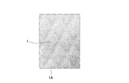
図2は、上記の手順で作製したテスト品1をダイヤ柄調の表皮材層1から撮影した写真である。図3は、上記の手順で作製したテスト品1をダイヤ柄調の第2多孔層41から撮影した写真である。(About the design of test product 1)
FIG. 2 is a photograph of the test product 1 produced by the above procedure taken from the diamond pattern-like skin material layer 1. FIG. 3 is a photograph of the test product 1 produced by the above procedure taken from the diamond pattern-like second
図3に示すように、本発明者は、上記凸部形成工程にてキルティング加工を施す際に、第1連結部50及び第2連結部51同士の間隔Dを所定長さ(例えば、5mm)以上確保することで、積層成形体100の意匠性を向上させることに成功した。具体的には、凸部形成工程で緩衝材層2の一方の面2Aに凸部2Tを形成した後に、押圧工程で表皮材層1の面1Aを第1多孔層40に向けて押圧して表皮材層1を緩衝材層2に接着させることで、表皮材層1の断面形状がなだらかな曲面形状になるように工夫した。その結果、図2に示すように、表皮材層1の面1Aにおいてダイヤ柄調の意匠上の形状的な仕上がりの柔らかさを出すことに成功した。
As shown in FIG. 3, the present inventor sets the distance D between the first connecting
また、テスト品1は、表皮材層1と緩衝材層2とを接着する前のキルティング加工において、緩衝材層2のみに起伏を付けた後に、第1接着剤層30で表皮材層1を第1多孔層40に接着させるので、表皮材層1における起伏表現の自由度を向上できることが分かった。
Further, in the test product 1, in the quilting process before adhering the skin material layer 1 and the
(テスト品2の作製について)
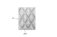
図4は、従来の方法で作製したテスト品2の概略構成を示す側断面図である。図5は、上記従来の手順で作製したテスト品2をダイヤ柄調の表皮材21から撮影した写真である。図6は、上記従来の手順で作製したテスト品2をダイヤ柄調の不織布24から撮影した写真である。(About the production of test product 2)
FIG. 4 is a side sectional view showing a schematic configuration of the
本発明者は、車両用シートメイン材のバック下部とクッション奥側の部品をテスト品2として、従来の方法で作製した(図4参照)。まず、図4に示すように、発泡ウレタン22の一方の面22Aに第1接着剤23Aで表皮材21を接着した。次に、発泡ウレタン22の他方の面22Bに第2接着剤23Bで不織布24を接着した。次に、表皮材21、第1接着剤23A、発泡ウレタン22、第2接着剤23B及び不織布24にキルティング加工を施した。これにより、表皮材21、第1接着剤23A、発泡ウレタン22、第2接着剤23B及び不織布24を糸25で連結し、テスト品2を作製した。
The present inventor manufactured the parts on the lower back side and the back side of the cushion of the vehicle seat main material as the
(テスト品2の意匠性について)
テスト品2に係る積層成形体200では、図4に示すように、表皮材21において第1接着剤23Aが形成されている側と反対側の面21Aは、上に凸をなしており、すなわち、負の曲率を有する。このため、面21Aの谷部分21Vには図4に示すような角が発生する。また、テスト品2に係る積層成形体200では、図4に示すように、不織布24において第2接着剤23Bが形成されている側と反対側の面24Aは、下に凸をなしており、すなわち、正の曲率を有する。このため、面24Aの谷部分24Vにも谷部分21Vと同様に図4に示すような角が発生する。
(About the design of test product 2)
In the laminated molded
上述のように、表皮材21の面21Aに発生した角と、不織布24の面24Aとに発生した角により、図5に示すように、テスト品2において表皮材21の面21Aに、ダイヤ柄調の意匠上の形状的な仕上がりの柔らかさを表現できないことが分かった。同様に、図6に示すように、テスト品2において不織布24の面24Aに、ダイヤ柄調の意匠上の形状的な仕上がりの柔らかさを表現できないことが分かった。
As described above, due to the corners generated on the
実施例1の積層成形体100では、表皮材層1において、緩衝材層2の一対の谷部2Vに挟まれた凸部2Tに対応する部分は、側面視において、下に凸をなしており、すなわち、正の曲率を有する。緩衝材層2において第2接着剤層31(すなわち、表皮材層1)が形成されている側の面2Aの谷部2Vに挟まれた凸部2Tは、側面視において、上に凸をなしており、すなわち、負の曲率を有する。即ち、実施例1の積層成形体100では、表皮材層1よりも下層にある緩衝材層2に予め起伏を付けた状態で、第1接着剤層30を用いて表皮材層1を緩衝材層2に接着できる。このため、表皮材層1の面1Aにおいて起伏の谷となる部分に従来のような角が出ない。これにより、表皮材層1の断面形状がなだらかな曲面形状になる。従って、積層成形体100を車両シートに張り込んだ際、表皮材層1の面1Aにおいて意匠上の形状的な仕上がりの柔らかさの視覚的効果を高めることができる。
In the laminated molded
実施例2は、表皮材層1及び第1接着剤層30にパーフォレーション加工を施す例である。
The second embodiment is an example in which the skin material layer 1 and the first
まず、構成を説明する。
実施例2における積層成形体は、実施例1と同様に、車両用内装品(例えば、車両シート等)に適用したものである。First, the configuration will be described.
The laminated molded product in the second embodiment is applied to an interior product for a vehicle (for example, a vehicle seat or the like) as in the first embodiment.
[積層成形体の全体構成]
図1は実施例2における積層成形体の概略構成を示す側断面図である。図7は実施例2における積層成形体を表皮材層1から見た図である。以下、図1に基づいて、積層成形体の全体構成を説明する。なお、図1では、パーフォレーションの穴の図示を省略している。[Overall composition of laminated molded product]
FIG. 1 is a side sectional view showing a schematic configuration of the laminated molded product according to the second embodiment. FIG. 7 is a view of the laminated molded product of Example 2 as viewed from the skin material layer 1. Hereinafter, the overall configuration of the laminated molded product will be described with reference to FIG. Note that in FIG. 1, the perforation holes are not shown.
積層成形体100は、図1に示すように、表皮材層1と、緩衝材層2と、接着剤層3と、多孔層4と、連結部5とを備える。接着剤層3は、第1接着剤層30と、第2接着剤層31と、第3接着剤層32とを備える。
As shown in FIG. 1, the laminated molded
表皮材層1及び第1接着剤層30には、表皮材層1及び第1接着剤層30をX方向に貫通し且つ空隙2Vhに連通するパーフォレーションの穴が形成される。即ち、実施例2では、自動車用のシート表皮材において意匠のため、あるいは空調機能が搭載された車両に関しては、体感温度又は室温によって温風・冷風をシート内部から室内に通風させるため、表皮材層1にパーフォレーション加工が施される。
なお、他の構成は、実施例1と同様であるので、対応する構成に同一符号を付して説明を省略する。The skin material layer 1 and the first
Since the other configurations are the same as those in the first embodiment, the corresponding configurations are designated by the same reference numerals and the description thereof will be omitted.
(パーフォレーション加工に起因した品質低下や生産性低下の発生メカニズム)
図7は、実施例2における積層成形体の比較例の積層成形体においてパーフォレーション加工に起因した品質低下が発生するメカニズムを示す説明図である。図8は、実施例2における積層成形体の比較例の積層成形体においてパーフォレーション加工に起因した生産性低下が発生するメカニズムを示す説明図である。ここで、上述したようなパーフォレーション加工が施されている部品に関しても、パーフォレーション加工の後に、更に、キルティング加工を施した部品が存在する。以下、図7及び図8に基づいて、部品の品質低下及び生産性低下が発生するメカニズムについて説明する。(Mechanism of quality deterioration and productivity deterioration due to perforation processing)
FIG. 7 is an explanatory diagram showing a mechanism in which quality deterioration occurs due to perforation processing in the laminated molded product of the comparative example of the laminated molded product in Example 2. FIG. 8 is an explanatory diagram showing a mechanism in which a decrease in productivity due to perforation processing occurs in the laminated molded product of the comparative example of the laminated molded product in Example 2. Here, as for the parts that have been perforated as described above, there are parts that have been further quilted after the perforation. Hereinafter, the mechanism by which the quality deterioration and the productivity deterioration of the parts occur will be described with reference to FIGS. 7 and 8.
(パーフォレーション加工に起因した品質低下の発生メカニズム)
図7に示すように、表皮材61の一方の面61Aにパーフォレーション加工を施した後に、表皮材61と発泡ウレタン層(不図示)を接着し、キルティング加工を行う。このため、図7の部分拡大図に示すように、パーフォレーションの穴61Hに針穴が落ちて、ステッチ65がジグザグ形状になる。このため、視覚的に品質が低下するという問題が起きていた。(Mechanism of quality deterioration caused by perforation processing)
As shown in FIG. 7, after perforation processing is performed on one
(パーフォレーション加工に起因した生産性低下の発生メカニズム)
また、上記改善のため、図8に示すように、キルティング加工用のステッチ75の付近にパーフォレーションの穴71Hが開かないように予め調整し、パンチング加工した表皮材71にキルティング加工を施す場合、穴71Hと穴71Hの中心を正確に狙ってステッチを行うことが困難であるという問題があった。また、そのような特殊なパーフォレーション加工を行うために時間を要し、生産性が低下するという問題があった。(Mechanism of productivity decrease due to perforation processing)
Further, for the above improvement, as shown in FIG. 8, when the perforation hole 71H is adjusted in advance so as not to be opened in the vicinity of the
これに対し、実施例2の積層成形体100は、キルティング加工用の第1連結部50と第2連結部51とは、図1に示すように、表皮材層1よりも下層にあるので、キルティング加工が施された部位を問わずに、パーフォレーション加工が施された表皮材層1で起伏表現がある意匠を構成できる。
On the other hand, in the laminated molded
また、実施例2の積層成形体100では、表皮材層1及び第1接着剤層30には、表皮材層1及び第1接着剤層30をX方向に貫通し且つ空隙2Vhに連通するパーフォレーションの穴が形成される。このため、空隙2VhによってZ方向に向かう空気の通路を形成できることに加え、パーフォレーションの穴によってX方向に向かう空気の通路を形成できる。これにより、X方向に向かう空気の通路が増えた分だけ、積層成形体100の通気性を更に向上できる。
Further, in the laminated molded
実施例3は、緩衝材層の成形を熱溶着で行う例である。 Example 3 is an example in which the cushioning material layer is formed by heat welding.
まず、構成を説明する。
実施例3における積層成形体は、実施例1と同様に、車両用内装品(例えば、車両シート等)に適用したものである。First, the configuration will be described.
The laminated molded product in the third embodiment is applied to an interior product for a vehicle (for example, a vehicle seat or the like) as in the first embodiment.
[積層成形体の全体構成]
図9は実施例3における積層成形体の概略構成を示す側断面図である。以下、図9に基づいて、積層成形体の全体構成を説明する。[Overall composition of laminated molded product]
FIG. 9 is a side sectional view showing a schematic configuration of the laminated molded product according to the third embodiment. Hereinafter, the overall configuration of the laminated molded product will be described with reference to FIG.
積層成形体300は、図9に示すように、表皮材層81と、緩衝材層82と、接着剤層83とを備える。積層成形体300は、緩衝材層82がX方向に圧縮された凹部82Cを有し、緩衝材層82の凹部82Cの両端には一対の谷部82Vを備えている。
As shown in FIG. 9, the laminated molded
表皮材層81は、表皮材(例えば、牛革)からなる。表皮材層81において、緩衝材層82の一対の谷部82Vに挟まれた平坦部82F(凹部底面部)に対応する部分は、側面視において、下に凸をなしており、すなわち、正の曲率を有する。
The
緩衝材層82は、緩衝材(例えば、発泡ウレタン)からなる。緩衝材層82において接着剤層83が形成されている側の面82Aの谷部82Vに挟まれた平坦部82Fは、側面視において、平坦な部位である。同様に、緩衝材層82において接着剤層83が形成されている側と反対側の面82Bの谷部82Vに挟まれた平坦部82Fは、側面視において、平坦な部位である。一対の谷部82Vは、Y方向に離間した位置に設けられる。その離間距離D1は、積層成形体300の意匠を表現するために必要な所定長さ(例えば5mm以上)に予め設定されている。緩衝材層82において接着剤層83が形成されている側の面82Aと、表皮材層81において接着剤層83が形成されている側の面81Bとの間には、緩衝材層82の谷部82Vに相当する部位に側面視において、略三角形状の空隙82Vhが形成される。この空隙82Vhは、Z方向に空気の流れを形成する空隙となる。
The
実施例3では、緩衝材層82の成形は熱溶着で行われる。その熱溶着は、緩衝材層82にウェルダー加工を施すことによって行われる。
In Example 3, the
接着剤層83は、接着剤(例えば、熱可塑性接着シート)からなる。接着剤層83は、表皮材層81と緩衝材層82との間に設けられ、表皮材層81を緩衝材層82に接着する。
The
次に、実験例2により本開示を具体的に説明する。ここでは、本実施形態に係る積層成形体300(図9参照)の意匠性を検討した実験結果について説明する。なお、本開示は、本実験例に限定されるものではない。より具体的に、本発明者は、上記テスト品2と、積層成形体300のテスト品(以下、テスト品3という)との比較により、両者の意匠性を評価する実験を行った。
Next, the present disclosure will be specifically described with reference to Experimental Example 2. Here, the experimental results of examining the design of the laminated molded product 300 (see FIG. 9) according to the present embodiment will be described. The present disclosure is not limited to this experimental example. More specifically, the present inventor conducted an experiment to evaluate the design of both the
(テスト品3の作製について)
本発明者は、車両用シートメイン材のバック下部とクッション奥側の部品をテスト品3として作製した。まず、表皮材層81(図9参照)として車両用本革を準備した。ここで、車両用本革の厚みは1.2±0.2mmとし、車両用本革のBLC(剛軟度)は33.8とした。接着剤層83として熱可塑性接着シートを準備した。緩衝材層82として発泡ウレタン(t2、50g、0.022g/cm3)を準備した。(About the production of test product 3)
The present inventor produced the parts on the lower back side and the back side of the cushion of the vehicle seat main material as the
続いて、本実験例では、凸部形成工程、接着剤層形成工程及び押圧工程をこの順に行い、テスト品3を作製した。
Subsequently, in this experimental example, the convex portion forming step, the adhesive layer forming step, and the pressing step were performed in this order to prepare the
(凸部形成工程)
凸部形成工程では、緩衝材層82にウェルダー加工を施した。その際、ウェルダー加工の条件は、電流を0.35Aとし、溶着時間を3.0秒とし、冷却時間を3.0秒とし、金型温度を90℃とした。そのウェルダー加工により、緩衝材層82を成形し、緩衝材層82の一方の面82A及び他方の面82Bに凸部82Tを形成した。その際、ウェルダー加工の条件は、一対の谷部82V同士の間隔(図9に示す離間距離D1)を最低でも5mm以上とした。(Convex forming process)
In the convex portion forming step, the
(接着剤層形成工程)
次の接着剤層形成工程では、凸部形成工程でウェルダー加工が施された緩衝材層82と、表皮材層81との間に、接着剤層83を挟んだ。これにより、表皮材層81の一方の面81B(図9参照)に、接着剤層83を形成した。(Adhesive layer forming process)
In the next adhesive layer forming step, the
(押圧工程)
次の押圧工程では、接着剤層形成工程で一方の面81Bに接着剤層83が形成された表皮材層81の他方の面81Aを所定の圧力で緩衝材層82の一方の面82Aに押し付けるプレス加工を施した。そのプレス加工により、接着剤層83で表皮材層81と緩衝材層82とを接着した。その際、プレス加工の条件は、温度を115℃とし、圧力を2000kg/0.6m2とし、加工時間を30秒とした。(Pressing process)
In the next pressing step, the
(凸部再形成工程)
次の凸部再形成工程では、押圧工程のプレス加工における所定の圧力(プレス圧)を開放することにより、プレス圧で押圧されていた緩衝材層82の復元力で緩衝材層82の一方の面82Aを膨れさせて空隙82Vhを形成し、緩衝材層82の一方の面82Aに凸部82Tを再形成した。これにより、表皮材層81の他方の面81Aは、側面視において、下に凸をなしており、すなわち、正の曲率を有し、緩衝材層82の一方の面82Aは、側面視において、平坦な形状に形成した(図9参照)。
(Convex reshaping process)
In the next convex portion reforming step, by releasing a predetermined pressure (press pressure) in the press working of the pressing step, one of the cushioning material layers 82 is restored by the restoring force of the
(テスト品3の意匠性について)
本発明者は、上記凸部形成工程にてキルティング加工を施す際に、一対の谷部82V同士の間隔の間隔D1を5mm以上確保することで、積層成形体300の意匠性を向上させることに成功した。具体的には、凸部形成工程で緩衝材層82の一方の面82Aに凸部82Tを形成した後に、押圧工程で表皮材層81の面81Aを緩衝材層82に向けて押圧して表皮材層81を緩衝材層82に接着させることで、表皮材層81の断面形状がなだらかな曲面形状になるように工夫した。その結果、表皮材層81の面81Aにおいてテスト品2と比べて意匠上の形状的な仕上がりの柔らかさを出すことに成功した。(About the design of test product 3)
The present inventor has determined to improve the design of the laminated molded
また、テスト品3は、表皮材層81と緩衝材層82とを接着する前のウェルダー加工において、緩衝材層82のみに起伏を付けた後に、接着剤層83で表皮材層81を緩衝材層82に接着させるので、表皮材層81における起伏表現の自由度をテスト品2と比べて向上できることが分かった。
Further, in the
また、実施例3の積層成形体300では、ウェルダー加工による熱溶着で、緩衝材層82を成形し、緩衝材層82の一方の面82A及び他方の面82Bに凸部82Tが形成される。このため、例えば縫着加工で緩衝材層82を成形する場合と比べてコスト面で非常に有利である。具体的には、縫着加工による成形は緩衝材層82のデザインに合わせて発泡成形用の金型を準備する必要があるが、熱溶着による加工の場合は、緩衝材層82を凹ませる部分の型枠を準備するだけで良く、コスト的に非常に有利である。また、切削加工による成形と比べても熱溶着による加工の場合は、工程が煩雑化せず、コスト的に非常に有利である。
Further, in the laminated molded
以上、本開示の積層成形体及びその製造方法を実施例1、実施例2及び実施例3に基づいて説明してきたが、具体的な構成については、これらの実施例に限られるものではなく、請求の範囲の各請求項に係る発明の要旨を逸脱しない限り、設計の変更や追加等は許容される。 Although the laminated molded article and the manufacturing method thereof of the present disclosure have been described above based on Examples 1, 2 and 3, the specific configuration is not limited to these Examples. As long as the gist of the invention according to each claim is not deviated from the claims, design changes and additions are permitted.
実施例1及び実施例2では、表皮材層1の下層にある緩衝材層2をキルティングされた発泡ウレタンで形成する例を示した。しかし、これに限られない。例えば、緩衝材層2は成形された発泡ウレタン(熱溶着加工、型に入れて発泡、切削加工など)であっても良い。また例えば、緩衝材層2はキルティングされた綿であっても良い。この場合、成型された発泡ウレタンの硬さを切削加工により形が崩れない程度の硬さに維持できれば、発泡ウレタンにキルティング加工を施さずに、発泡ウレタンに切削加工を施すことによって積層成形体100に加飾を施しても良い。発泡ウレタン自体に切削加工を施す場合には、ステッチで発泡ウレタンを縫う際に発泡ウレタンの破れ等を防ぐ第1多孔層40を緩衝材層2に設けなくても良い。また、発泡ウレタンが柔らかくても、発泡ウレタン自体に切削加工を施して積層成形体100に加飾を施す場合も同様に、発泡ウレタンの破れ等を防ぐ第1多孔層40を緩衝材層2に設けなくても良い。
In Examples 1 and 2, an example was shown in which the
実施例1及び実施例2では、表皮材層1を牛革で形成する例を示し、実施例3では、表皮材層81を牛革で形成する例を示した。しかし、これに限られない。例えば、表皮材層1又は表皮材層81は、本革、合成皮革、人工皮革、ポリ塩化ビニル(PVC)及び布のうちいずれか一つであれば良い。
In Example 1 and Example 2, an example in which the skin material layer 1 is formed of cowhide is shown, and in Example 3, an example in which the
実施例1及び実施例2では、多孔層4を不職布で形成する例を示した。しかし、これに限られない。例えば、多孔層4はメッシュ素材であっても良い。要するに、多孔層4は、緩衝材層2の内部と外部とを連通させる材料であれば良い。
In Example 1 and Example 2, an example in which the
実施例1及び実施例2では、表皮材層1及び第2多孔層41にダイヤ調の柄を形成する例を示した。しかし、これに限られない。例えば、表皮材層1及び第2多孔層41に直線状のボーダー柄、曲線状の柄を形成しても良い。要するに、表皮材層1及び第2多孔層41に形成する柄は、意匠上の形状的な仕上がりの柔らかみがあれば良い。
In Example 1 and Example 2, an example of forming a diamond-like handle on the skin material layer 1 and the second
実施例1、実施例2及び実施例3では、本開示の積層成形体及びその製造方法を、車両シートに適用する例を示した。しかし、これに限られない。本開示の積層成形体及びその製造方法は、インストルメントパネル、ドアトリム及びシートバック等の自動車内装品も適用することができる。 In Example 1, Example 2, and Example 3, an example in which the laminated molded article of the present disclosure and the manufacturing method thereof are applied to a vehicle seat is shown. However, it is not limited to this. The laminated molded article and the manufacturing method thereof of the present disclosure can also be applied to automobile interior parts such as instrument panels, door trims and seat backs.
実施例1、実施例2及び実施例3では、本開示の積層成形体及びその製造方法を、自動車等の車両用内装品に適用する例を示した。しかし、本開示の積層成形体及びその製造方法は、車両以外の乗り物(例えば、鉄道車両、プレジャーボート等)の内装品、家具(例えば、革製ソファ等)に対しても適用することができる。 In Example 1, Example 2, and Example 3, an example in which the laminated molded article of the present disclosure and the manufacturing method thereof are applied to an interior product for a vehicle such as an automobile is shown. However, the laminated molded article and its manufacturing method of the present disclosure can also be applied to interior parts and furniture (for example, leather sofas, etc.) of vehicles other than vehicles (for example, railroad vehicles, pleasure boats, etc.). ..
実施例1では、第1連結部50と、第2連結部51との離間距離Dを5mm以上に設定し、実施例3では、一対の谷部82Vの離間距離D1を5mm以上に設定する例を示した。しかし、これに限られない。例えば、離間距離D、D1は、5mm未満に設定されても良い。要するに、離間距離D、D1は、それぞれ、積層成形体100、300の意匠を表現するために必要な長さに設定できれば良い。
In the first embodiment, the separation distance D between the first connecting
本出願は、2016年11月22日に日本国特許庁に出願された特願2016−227009号に基づいて優先権を主張し、その全ての開示は完全に本明細書で参照により組み込まれる。 This application claims priority under Japanese Patent Application No. 2016-22709 filed with the Japan Patent Office on November 22, 2016, the entire disclosure of which is incorporated herein by reference in its entirety.
1、81 表皮材層
1A 表皮材層1において第1接着剤層30が形成されている側と反対側の面
1B 表皮材層1において第1接着剤層30が形成されている側の面
1L 折り返し部
2、82 緩衝材層
2A 緩衝材層2において第2接着剤層31が形成されている側の面
2B 緩衝材層2において第3接着剤層32が形成されている側の面
2C、82C 凹部
2T 凸部(凹部底面部)
2V、82V 谷部
2Vh、82Vh 空隙
3、83 接着剤層
4 多孔層
5 連結部
30 第1接着剤層
31 第2接着剤層
32 第3接着剤層
40 第1多孔層
41 第2多孔層
50 第1連結部
51 第2連結部
81A 表皮材層81において接着剤層83が形成されている側と反対側の面
81B 表皮材層81において接着剤層83が形成されている側の面
82A 緩衝材層82において接着剤層83が形成されている側の面
82B 緩衝材層82において接着剤層83が形成されている側と反対側の面
82F 平坦部(凹部底面部)
100、300 積層成形体1, 81
2V, 82V Valley 2Vh,
100, 300 laminated molded parts
Claims (5)
緩衝材からなる緩衝材層と、
接着剤からなり、前記表皮材層と前記緩衝材層との間に設けられた接着剤層とを備え、
前記緩衝材層が凹部を有しており、
前記緩衝材層の凹部は一対の谷部を備え、
前記表皮材層において前記一対の谷部に挟まれた凹部底面部に対応する部分は、側面視において、正の曲率を有し、
前記緩衝材層において前記接着剤層が形成されている側の面における前記谷部に挟まれた凹部底面部は、側面視において、負の曲率を有するか又は平坦であることを特徴とする積層成形体。 The epidermis material layer made of epidermis material and
A cushioning material layer made of cushioning material and
It is made of an adhesive and includes an adhesive layer provided between the skin material layer and the cushioning material layer.
The cushioning material layer has a recess,
The recess of the cushioning material layer has a pair of valleys and
The portion of the epidermis layer corresponding to the bottom surface of the recess sandwiched between the pair of valleys has a positive curvature in side view.
The bottom surface of the recess sandwiched between the valleys on the surface of the cushioning material layer on the side on which the adhesive layer is formed has a negative curvature or is flat in a side view. Molded body.
前記接着剤層と前記緩衝材層との間に設けられた多孔層を備えることを特徴とする積層成形体。 In the laminated molded article according to claim 1,
A laminated molded product comprising a porous layer provided between the adhesive layer and the cushioning material layer.
前記多孔層は、不織布及びメッシュ素材のうちいずれか一つであることを特徴とする積層成形体。 In the laminated molded article according to claim 2,
A laminated molded product, wherein the porous layer is any one of a non-woven fabric and a mesh material.
前記表皮材層において前記接着剤層が形成されている側の面と、前記緩衝材層において前記接着剤層が形成されている側の面との間には、前記緩衝材層の谷部に相当する部位に側面視において、空隙が形成されることを特徴とする積層成形体。 In the laminated molded article according to any one of claims 1 to 3.
Between the surface of the skin material layer on which the adhesive layer is formed and the surface of the cushioning material layer on which the adhesive layer is formed, a valley portion of the cushioning material layer is formed. A laminated molded body characterized in that voids are formed in a corresponding portion in a side view.
表皮材からなる表皮材層の一方の面に、接着剤からなる接着剤層を形成する接着剤層形成工程と、
前記表皮材層を所定の圧力で前記緩衝材層の一方の面に押し付ける押圧工程と、
前記所定の圧力を開放することにより、押圧されていた前記緩衝材層の復元力で前記緩衝材層の一方の面を膨れさせて前記緩衝材層の一方の面に凸部を再形成する凸部再形成工程を順に行うことにより、
前記表皮材層の他方の面は、側面視において、正の曲率を有し、
前記緩衝材層の一方の面は、側面視において、負の曲率を有するか又は平坦となる形状を形成することを特徴とする積層成形体の製造方法。 A convex portion forming step of forming a convex portion on one surface of a cushioning material layer made of a cushioning material,
An adhesive layer forming step of forming an adhesive layer made of an adhesive on one surface of the skin material layer made of the skin material,
A pressing step of pressing the skin material layer against one surface of the cushioning material layer with a predetermined pressure,
By releasing the predetermined pressure, one surface of the cushioning material layer is swelled by the restoring force of the cushioning material layer that has been pressed, and a convex portion is formed on one surface of the cushioning material layer. By performing the part reforming steps in order,
The other surface of the epidermis layer has a positive curvature in lateral view and
A method for producing a laminated molded product, wherein one surface of the cushioning material layer forms a shape having a negative curvature or becoming flat in a side view.
Applications Claiming Priority (3)
| Application Number | Priority Date | Filing Date | Title |
|---|---|---|---|
| JP2016227009 | 2016-11-22 | ||
| JP2016227009 | 2016-11-22 | ||
| PCT/JP2017/040524 WO2018096944A1 (en) | 2016-11-22 | 2017-11-10 | Laminated molded body and method for manufacturing same |
Publications (2)
| Publication Number | Publication Date |
|---|---|
| JPWO2018096944A1 JPWO2018096944A1 (en) | 2019-10-17 |
| JP6772292B2 true JP6772292B2 (en) | 2020-10-21 |
Family
ID=62194907
Family Applications (1)
| Application Number | Title | Priority Date | Filing Date |
|---|---|---|---|
| JP2018552502A Active JP6772292B2 (en) | 2016-11-22 | 2017-11-10 | Laminated molded product and its manufacturing method |
Country Status (5)
| Country | Link |
|---|---|
| US (1) | US11001030B2 (en) |
| EP (1) | EP3546206B1 (en) |
| JP (1) | JP6772292B2 (en) |
| CN (1) | CN109963706B (en) |
| WO (1) | WO2018096944A1 (en) |
Families Citing this family (6)
| Publication number | Priority date | Publication date | Assignee | Title |
|---|---|---|---|---|
| US10246153B2 (en) * | 2012-10-11 | 2019-04-02 | Polaris Industries Inc. | Side-by-side vehicle |
| WO2020166052A1 (en) * | 2019-02-15 | 2020-08-20 | 河西工業株式会社 | Surface material for automobile interior parts |
| JP7272081B2 (en) | 2019-04-17 | 2023-05-12 | トヨタ紡織株式会社 | Skin material manufacturing method |
| US12343973B2 (en) | 2019-11-21 | 2025-07-01 | Midori Auto Leather Co., Ltd. | Laminated molded body and method for manufacturing same |
| KR20230037769A (en) * | 2021-09-10 | 2023-03-17 | 현대자동차주식회사 | Eco-friendly automotive interior parts and manufacturing method thereof |
| JP7576803B2 (en) * | 2022-08-02 | 2024-11-01 | 住江織物株式会社 | Vehicle interior decorative sheet material |
Family Cites Families (11)
| Publication number | Priority date | Publication date | Assignee | Title |
|---|---|---|---|---|
| JPH037436Y2 (en) | 1985-04-08 | 1991-02-25 | ||
| JPH0723665A (en) | 1993-07-09 | 1995-01-27 | Hitachi Ltd | Multiple film |
| JP2000158573A (en) * | 1998-11-30 | 2000-06-13 | Asahi:Kk | Quilting material and its manufacturing method |
| JP3037948B1 (en) * | 1999-05-14 | 2000-05-08 | 弘 生田 | Quilting processing method using adhesive |
| US7201816B2 (en) * | 2001-12-21 | 2007-04-10 | Invista North America S.A.R.L. | High bulk composite sheets and method for preparing |
| US6893086B2 (en) * | 2002-07-03 | 2005-05-17 | W.E.T. Automotive Systems Ltd. | Automotive vehicle seat insert |
| JP4809599B2 (en) | 2004-10-25 | 2011-11-09 | テイ・エス テック株式会社 | Seat seat, method of manufacturing the same, and seat seat recovery processing method |
| JP5768421B2 (en) * | 2011-03-16 | 2015-08-26 | 東洋紡株式会社 | Adsorption sheet |
| JP5700812B2 (en) * | 2011-03-31 | 2015-04-15 | アキレス株式会社 | Sheet material |
| JP6336910B2 (en) | 2012-10-01 | 2018-06-06 | テイ・エス テック株式会社 | Seat backrest |
| JP6100111B2 (en) * | 2013-07-04 | 2017-03-22 | 株式会社タチエス | Seat cushion |
-
2017
- 2017-11-10 JP JP2018552502A patent/JP6772292B2/en active Active
- 2017-11-10 WO PCT/JP2017/040524 patent/WO2018096944A1/en not_active Ceased
- 2017-11-10 US US16/462,925 patent/US11001030B2/en active Active
- 2017-11-10 CN CN201780071637.1A patent/CN109963706B/en active Active
- 2017-11-10 EP EP17873038.8A patent/EP3546206B1/en active Active
Also Published As
| Publication number | Publication date |
|---|---|
| US20190322072A1 (en) | 2019-10-24 |
| EP3546206A4 (en) | 2020-08-05 |
| JPWO2018096944A1 (en) | 2019-10-17 |
| WO2018096944A1 (en) | 2018-05-31 |
| US11001030B2 (en) | 2021-05-11 |
| EP3546206B1 (en) | 2022-03-16 |
| CN109963706B (en) | 2022-02-25 |
| EP3546206A1 (en) | 2019-10-02 |
| CN109963706A (en) | 2019-07-02 |
Similar Documents
| Publication | Publication Date | Title |
|---|---|---|
| JP6772292B2 (en) | Laminated molded product and its manufacturing method | |
| US4541885A (en) | Method of manufacturing a vehicle seat cover | |
| US11840053B2 (en) | Skin material and method for producing the same | |
| CN102803020B (en) | Trim panel of motor vehicles | |
| JP4766322B2 (en) | Vehicle interior parts and manufacturing method thereof | |
| US12343973B2 (en) | Laminated molded body and method for manufacturing same | |
| JP2011194932A (en) | Interior parts for vehicle | |
| CN106163867A (en) | Method for manufacturing an element with a cover, and such an element | |
| US11267190B2 (en) | Method for producing skin material | |
| JP2019072867A (en) | Skin material and structure, and method for manufacturing skin material | |
| CN118201808A (en) | Vehicle seat and method of manufacturing a vehicle seat | |
| JP2015160484A (en) | Method of manufacturing interior automotive trim, and interior automotive trim | |
| KR101879687B1 (en) | vehicle seat with softness and manufacturing method thereof | |
| JP5931552B2 (en) | Vehicle interior member and manufacturing method thereof | |
| JPS608065A (en) | Manufacture of polyurethane foam cushion | |
| JP6607100B2 (en) | Manufacturing method for vehicle interior products | |
| JP2017159629A (en) | Inner package and manufacturing method therefor | |
| JP2009107132A (en) | Laminated body and method for producing the same | |
| JP2693490B2 (en) | Manufacturing method of vehicle seat | |
| JPH07156316A (en) | Skin material for seat | |
| JP2016101324A (en) | Vehicle seat and method for producing the same | |
| JPS60160990A (en) | Production of trim cover | |
| JP2014193577A (en) | Resin molding and production method of the same | |
| JP2018043556A (en) | Method for producing skin material and skin material | |
| JPS60253486A (en) | Integrally molded seat body |
Legal Events
| Date | Code | Title | Description |
|---|---|---|---|
| A621 | Written request for application examination |
Free format text: JAPANESE INTERMEDIATE CODE: A621 Effective date: 20190520 |
|
| A131 | Notification of reasons for refusal |
Free format text: JAPANESE INTERMEDIATE CODE: A131 Effective date: 20200526 |
|
| A521 | Request for written amendment filed |
Free format text: JAPANESE INTERMEDIATE CODE: A523 Effective date: 20200702 |
|
| TRDD | Decision of grant or rejection written | ||
| A01 | Written decision to grant a patent or to grant a registration (utility model) |
Free format text: JAPANESE INTERMEDIATE CODE: A01 Effective date: 20200923 |
|
| A61 | First payment of annual fees (during grant procedure) |
Free format text: JAPANESE INTERMEDIATE CODE: A61 Effective date: 20200930 |
|
| R150 | Certificate of patent or registration of utility model |
Ref document number: 6772292 Country of ref document: JP Free format text: JAPANESE INTERMEDIATE CODE: R150 |
|
| R250 | Receipt of annual fees |
Free format text: JAPANESE INTERMEDIATE CODE: R250 |
|
| R250 | Receipt of annual fees |
Free format text: JAPANESE INTERMEDIATE CODE: R250 |