JP6720254B2 - Optical fiber retainer - Google Patents
Optical fiber retainer Download PDFInfo
- Publication number
- JP6720254B2 JP6720254B2 JP2018165210A JP2018165210A JP6720254B2 JP 6720254 B2 JP6720254 B2 JP 6720254B2 JP 2018165210 A JP2018165210 A JP 2018165210A JP 2018165210 A JP2018165210 A JP 2018165210A JP 6720254 B2 JP6720254 B2 JP 6720254B2
- Authority
- JP
- Japan
- Prior art keywords
- optical fiber
- support
- tube
- optical
- heat
- Prior art date
- Legal status (The legal status is an assumption and is not a legal conclusion. Google has not performed a legal analysis and makes no representation as to the accuracy of the status listed.)
- Active
Links
- 239000013307 optical fiber Substances 0.000 title claims description 210
- 230000003287 optical effect Effects 0.000 claims description 75
- 239000004831 Hot glue Substances 0.000 claims description 40
- 239000002184 metal Substances 0.000 claims description 15
- 229910052751 metal Inorganic materials 0.000 claims description 15
- 229920005989 resin Polymers 0.000 claims description 7
- 239000011347 resin Substances 0.000 claims description 7
- 239000000945 filler Substances 0.000 claims description 5
- 239000000853 adhesive Substances 0.000 claims description 2
- 230000001070 adhesive effect Effects 0.000 claims description 2
- 239000012943 hotmelt Substances 0.000 claims 1
- 239000010410 layer Substances 0.000 description 30
- 230000002093 peripheral effect Effects 0.000 description 21
- 238000003780 insertion Methods 0.000 description 17
- 230000037431 insertion Effects 0.000 description 17
- 230000000717 retained effect Effects 0.000 description 14
- 238000012986 modification Methods 0.000 description 8
- 230000004048 modification Effects 0.000 description 8
- 238000010438 heat treatment Methods 0.000 description 7
- 239000000463 material Substances 0.000 description 7
- 229910000831 Steel Inorganic materials 0.000 description 5
- 239000010959 steel Substances 0.000 description 5
- -1 polyethylene Polymers 0.000 description 4
- 150000001875 compounds Chemical class 0.000 description 3
- 238000002788 crimping Methods 0.000 description 3
- 239000000835 fiber Substances 0.000 description 3
- 238000009413 insulation Methods 0.000 description 3
- 238000005304 joining Methods 0.000 description 3
- 239000013535 sea water Substances 0.000 description 3
- XEEYBQQBJWHFJM-UHFFFAOYSA-N Iron Chemical compound [Fe] XEEYBQQBJWHFJM-UHFFFAOYSA-N 0.000 description 2
- 239000004743 Polypropylene Substances 0.000 description 2
- 230000005540 biological transmission Effects 0.000 description 2
- 230000015556 catabolic process Effects 0.000 description 2
- 239000000470 constituent Substances 0.000 description 2
- 229920001971 elastomer Polymers 0.000 description 2
- 239000005038 ethylene vinyl acetate Substances 0.000 description 2
- 238000009434 installation Methods 0.000 description 2
- 238000012423 maintenance Methods 0.000 description 2
- 229920001200 poly(ethylene-vinyl acetate) Polymers 0.000 description 2
- 229920001707 polybutylene terephthalate Polymers 0.000 description 2
- 230000001681 protective effect Effects 0.000 description 2
- 238000003860 storage Methods 0.000 description 2
- XLYOFNOQVPJJNP-UHFFFAOYSA-N water Substances O XLYOFNOQVPJJNP-UHFFFAOYSA-N 0.000 description 2
- 239000004698 Polyethylene Substances 0.000 description 1
- 239000004809 Teflon Substances 0.000 description 1
- 229920006362 Teflon® Polymers 0.000 description 1
- 238000005452 bending Methods 0.000 description 1
- 239000011248 coating agent Substances 0.000 description 1
- 238000000576 coating method Methods 0.000 description 1
- 238000004891 communication Methods 0.000 description 1
- 238000001816 cooling Methods 0.000 description 1
- 238000013461 design Methods 0.000 description 1
- 238000006073 displacement reaction Methods 0.000 description 1
- 239000012212 insulator Substances 0.000 description 1
- 229910052742 iron Inorganic materials 0.000 description 1
- 230000014759 maintenance of location Effects 0.000 description 1
- 238000004519 manufacturing process Methods 0.000 description 1
- 239000000155 melt Substances 0.000 description 1
- 238000000034 method Methods 0.000 description 1
- 239000004033 plastic Substances 0.000 description 1
- 229920003023 plastic Polymers 0.000 description 1
- 229920000573 polyethylene Polymers 0.000 description 1
- 229920001155 polypropylene Polymers 0.000 description 1
- 238000012545 processing Methods 0.000 description 1
- 238000011084 recovery Methods 0.000 description 1
- 229920002379 silicone rubber Polymers 0.000 description 1
- 239000004945 silicone rubber Substances 0.000 description 1
- 239000002356 single layer Substances 0.000 description 1
- 229910001220 stainless steel Inorganic materials 0.000 description 1
- 229920005992 thermoplastic resin Polymers 0.000 description 1
Images




Landscapes
- Mechanical Coupling Of Light Guides (AREA)
- Light Guides In General And Applications Therefor (AREA)
Description
本発明はファイバユニットとしてルースチューブ型ユニットを使用し、または、それに準ずる構成を持つ光ファイバケーブルの光ファイバ端末の引留め装置に関し、特に外部より大きな張力の印加される海底ケーブルに使用して好適なものである。 The present invention relates to a device for retaining an optical fiber terminal of an optical fiber cable which uses a loose tube type unit as a fiber unit or has a structure corresponding to the loose tube type unit, and is particularly suitable for use in a submarine cable to which a larger tension is applied than the outside. It is something.
海底光ケーブルの中心部に内装される光ファイバユニットとして、従来使用されてきたタイト型の光ファイバユニットに代わって、通信回線の増加要求に応えるためにより多くの光ファイバを挿通させる目的で開発されたルースチューブ型ユニットが使用される傾向にある。 As an optical fiber unit to be installed in the center of the submarine optical cable, it was developed with the aim of inserting more optical fibers in order to meet the increasing demand for communication lines, instead of the tight type optical fiber unit that has been used conventionally. Loose tube type units tend to be used.
このような海底光ケーブルは、通常大陸と大陸間、または大陸と島の間に布設されるため、伝送された信号を中継する中継器を介して長尺のケーブルが海底に布設される。複数箇所でケーブルと中継器との接続や長尺のケーブル同士の接続を行う必要があるが、この種の海底光ケーブルにおいては、深海での布設・回収に十分耐えるように、ケーブルを光学的、電気的、かつ機械的に接続する(いわゆる引留める)必要がある。 Since such a submarine optical cable is usually laid between continents or between continents and islands, a long cable is laid on the seabed via a repeater that relays a transmitted signal. It is necessary to connect the cable to the repeater or connect the long cables to each other at multiple points, but with this type of submarine optical cable, the cable must be optical, so that it can withstand the installation and recovery in the deep sea. It is necessary to make an electrical and mechanical connection (so-called retaining).
下記特許文献1には、海底光ケーブルに用いられる引留め部を有するルースチューブ型の光ファイバ及び当該光ファイバを引留める光ファイバ引留め装置が開示されている。
光ファイバ引留め装置は、後述するジョイントボックスのような端末接続装置の内部に設けられ、いずれもケーブルを機械的、電気的、及び光学的に接続する。即ち、光ファイバと給電路の接続、各抗張力体等の引留めとケーブル間の張力の伝達を行う。
The optical fiber retaining device is provided inside a terminal connecting device such as a joint box described later, and all of them connect the cables mechanically, electrically, and optically. That is, the connection between the optical fiber and the power supply path, the retention of each tensile strength member, and the transmission of the tension between the cables are performed.
まず図1を用いて、海底光ケーブル50x(以下、光ケーブル50xとも表記する。)の構造例を説明する。図1Aは光ケーブル50xの斜視図であり、図1Bは光ケーブル50xの軸線に直角な面で切断した断面図である。
First, a structural example of a submarine
光ケーブル50xは、ルースチューブ型光ファイバユニット1(以下、光ファイバユニット1とも表記する。)と、光ファイバユニット1を水圧から保護するための耐圧層2と、光ケーブル50xの布設時の負荷に十分耐える抗張力を付加し、かつ、障害に対してケーブルを保護するための抗張力体層3と、抗張力体層3の結束と気密を保ち、中継器への給電路となる金属チューブ層4と、海水との絶縁及び機械的保護を目的とするポリエチレン等で形成する絶縁層(シース)5、6を有する。
The
光ファイバユニット1は、ジェリー状の充填材(コンパウンド)1cを介して、PBT(Polybutylene Terephthalate)やPP(Polypropylene)等のプラスチックで成形したルースチューブ1d内に複数本の光ファイバ1aを挿通したものである。
なお厳密には、光ファイバにおけるガラス質のコアとクラッドのみを光ファイバ素線と、当該光ファイバ素線の上に被覆を施したものを光ファイバ心線と呼ぶ場合があるが、以下、特に素線・心線を区別せずに共に光ファイバと呼ぶ。
また光ファイバは、予め数本の光ファイバを並列にテープ状に拘束している光ファイバテープ心線の形で供給することもできる。
The
Strictly speaking, only the glassy core and clad in the optical fiber may be referred to as an optical fiber element wire, and a coating on the optical fiber element wire may be referred to as an optical fiber core wire. Both optical fiber and optical fiber are called without distinction.
The optical fiber can also be supplied in the form of an optical fiber ribbon, in which several optical fibers are preliminarily bound in parallel in a tape shape.
耐圧層2は、断面が扇形の鉄等の金属製の分割個片2aを3個縦添えして組み合わせることで形成される。
The
耐圧層2の外周に、ケーブルに加わる引張力に十分対応できるように、複数本の鋼線(以下、抗張力線とも表記する。)3aを撚り合わせて構成した抗張力体層3が形成される。耐圧層2の外周面、金属チューブ層4の内周面及び抗張力線3aの外周面で区画された空間に防水コンパウンド8が長手方向に間欠的に充填されている。
On the outer periphery of the pressure
抗張力体層には上記と異なった構成の海底光ケーブル50y(以下、光ケーブル50yとも表記する。)も使用される。図2Aの斜視図、図2Bの断面図で示す例は耐圧層の構成が変化している。即ち、耐圧層が内層の抗張力線3aと外層の抗張力線3bからなる2層に撚り合わされている抗張力線の競り合いによって光ファイバユニット1の外周に耐圧殻が実現するように構築されている。
光ファイバユニット1の外周面と抗張力線3aが光ファイバユニット1と対向する側の曲面との間に防水コンパウンド8を充填することで、耐圧殻(実質的には抗張力線3aの内面を直径とする殻)がルースチューブ1dを拘束する。
なお、金属チューブ層4とその外部の絶縁層5、6は図1と同様の構成とされている。
A submarine
By filling the
The
ここで図3を用いて、光ケーブル50x、50yから延びる光ファイバ1aに形成される引留め部30について説明する。図3Aは引留め部30の加熱前の状態を示しており、図3Bは引留め部30の加熱後の状態を示している。
引留め部30は中空のほぼ円形の断面を持つ熱収縮チューブ33の中空部に、ほぼ楕円状の断面を持ったチューブ状のホットメルト型接着剤31、及び、細長い棒状の支持体32が挿通されている。ホットメルト型接着剤31としては熱可塑性樹脂を基材とし、例えばEVA(Ethylene-vinyl acetate copolymer)等が用いられる。なお、図3A及び図3Bで右方向が光ケーブル側、左方向が端末接続装置での接続側となる。
Here, the
In the
支持体32は、例えばステンレス鋼線(SUS:Stainless Used Steel)等の金属線で形成される。支持体32の一端(図で右側)の端部は、熱収縮チューブ33の端部と位置がほぼ一致し、他端(図で左側)は後述する支持体引留め用の支持スリーブであるカシメスリーブ34を取り付けるための所定長が延長されている。
The
光ケーブルから取り出された複数本の光ファイバ1aの端末部を、ホットメルト型接着剤31の孔に挿通する。光ファイバ1aの接続側となる先端部は、接続加工が十分可能な長さとされている。
なお、後に詳細を説明する図4Bに示すように、光ケーブル(ここでは一例として光ケーブル50xを用いて説明する。)の外周部分を構成する絶縁層(シース)5、6が取り除かれ、耐圧層2や抗張力層3の構成部材は別途端末接続装置に引留められる。これにより光ケーブル本体が引き留められることとなる。
The end portions of the plurality of
As shown in FIG. 4B, which will be described in detail later, the insulating layers (sheath) 5 and 6 forming the outer peripheral portion of the optical cable (here, the
加熱前の状態においては、図3Aに示すように、ホットメルト型接着剤31の孔に複数本の光ファイバ1aが無理なく挿通され、更に、ホットメルト型接着剤31と支持体32が無理なく熱収縮チューブ33の孔に挿通されている。
In the state before heating, as shown in FIG. 3A, the plurality of
熱収縮チューブ33を加熱すると、ホットメルト型接着剤31は軟化溶融して光ファイバ1aや支持体32の隙間に流れ込み、また、熱収縮チューブ33は加熱によって、図3Bに示すように各部の長さが縮み、特にチューブの直径が小となる。熱収縮チューブ33の材質としては熱収縮性シリコーンゴム等が用いられる。
When the heat-
光ファイバ1aや支持体32の周囲を隙間なく充たしたホットメルト型接着剤31は縮径された熱収縮チューブ33の孔部に充填される。
加熱を停止し温度が下がると、ホットメルト型接着剤31は凝固して光ファイバ1aや支持体32を接着し、熱収縮チューブ33とも一体化して引留め部30を形成する。
The hot-
When the heating is stopped and the temperature is lowered, the
そして図3Bの左端に示すように、支持体32の先端近くに(一点鎖線で示す)カシメスリーブ34を固着し、このカシメスリーブ34を介して支持体32を端末接続装置の耐圧シリンダまたは相当部材に引留める。
Then, as shown in the left end of FIG. 3B, a caulking sleeve 34 (indicated by a chain line) is fixed near the tip of the supporting
次に光ファイバを引き留めるための端末接続装置であるジョイントボックス20について図4Aを用いて説明する。
ジョイントボックス20では、左右から挿入された光ケーブル50a、50bがブーツ25の中心の挿入孔23aを挿通して、中央部のジョイントボックス本体20aに導かれる。中央部の円柱状のカバー21の内部のジョイントボックス本体20aで光ケーブル50a、50bの機械的、電気的、及び光学的な接続が行われる。ここでは一例として、光ケーブル50a、50bとして光ケーブル50xを用いて説明する。
Next, the
In the
図4Bは、ジョイントボックス20の右半分に相当する円SP1の内部を、光ケーブルの軸線を含む平面で切断した断面図である。
引留め部30は、テーパーピン13、フランジ14、クランプナット15の中心に設けられた孔13a、14a、15aを挿通する。支持体32の先端部は耐圧シリンダ28内部に到達している。これにより、光ファイバ1aに形成された引留め部30は、アンカーディスク11によって支承される。
FIG. 4B is a cross-sectional view of the inside of the circle SP1 corresponding to the right half of the
The retaining
ここで、特許文献1に記載の発明においては、支持体32の左方先端部に固着したカシメスリーブ34を用いて光ファイバ1aを引き留める。
支持体32にカシメスリーブ34を固着するには、例えばカシメにより固着することができる。カシメ工程を分割個片2aや、鋼線(抗張力線)3aを引き留めた後に行うことで、光ファイバを最適な張力で引き留めることができる。即ち、支持体32を図で左方に引き、適度の張力を光ファイバに力をかけた状態でカシメスリーブ34を固着すればよい。
Here, in the invention described in
The
カシメスリーブ34はほぼ円筒形の部材で中心の孔に支持体32を挿通し、例えば、外部から力を加えてカシメスリーブ34を変形させて支持体32に圧着して固定する構造となっている。
カシメスリーブ34は種々の引き留め方法(支承方法)が可能であるが、一例として、図4Cに示す板金製の支持金具17をアンカーディスク11にビス17bで止め、先端の溝17aに支持体32を挿通し、カシメスリーブ34の右端を支持金具17で支承して引き留めている。
The
Although the
図4Bに示す光ファイバ引留め装置においては、支持金具17の溝17a(図4C)に支持体32を挿通し、カシメスリーブ34の右端を支持金具17で支承することで、光ファイバ1aの引き留めを実現している。つまり、光ファイバ1aの引き留めにあたり、カシメスリーブ34を図の支持体32の左方先端部に固着する必要がある。これにより、支持体32においてカシメスリーブ34の位置は容易に変更できない状態となる。つまり、光ファイバ1aのスラックを調節することが難しい。ここでスラックとは、光ファイバやケーブル等の長さについて、直線距離よりも若干長めとなるようなゆとりを設けておくことをいう。
In the optical fiber retaining device shown in FIG. 4B, the
そのため、一度カシメスリーブ34を支持体32に形成すると、後発的に光ファイバのスラックを調節することが必要になった場合であっても、図の左右方向に支持体32を移動させることによる光ファイバの張力の調整が困難となる。
Therefore, once the
そこで本発明は、後発的に光ファイバ1aのスラックを調節することが必要になった際、例えば図4Bに示すような支持体32の位置の調節を簡易な操作により可能とすることで、容易に当該スラックを調節することができる光ファイバ引留め装置を提供することを目的とする。
Therefore, in the present invention, when it becomes necessary to adjust the slack of the
本発明は、単数または複数本の光ファイバをジェリー状充填剤とともに金属製または樹脂製の円筒状のチューブに挿通したルースチューブ型ユニットを有する光ケーブルを接続する端末接続装置の内部に設置され、前記光ケーブルに挿通された前記光ファイバを前記端末接続装置に引留める光ファイバ引留め装置であって、中空部を有する熱収縮チューブと、前記光ケーブルとは別体に形成され中空部を有し前記熱収縮チューブと同等の熱収縮が生じない光ファイバ保護管とが軸線方向に連結され、中空部を有するホットメルト型接着剤が前記熱収縮チューブの中空部に挿入され、前記光ファイバが前記光ファイバ保護管の中空部及び前記ホットメルト型接着剤の中空部に挿入され、支持体の一端が前記熱収縮チューブの中空部に挿入された状態において、前記ホットメルト型接着剤が溶融され、かつ前記熱収縮チューブが収縮されることで、前記支持体の一端部及び前記光ファイバが共に一体構造として形成された光ファイバ引留め部と、
前記支持体の、前記光ファイバ引留め部から延出した部分を、着脱可能に固定する支持体固定部と、を備えたものである。
The present invention is installed inside a terminal connection device for connecting an optical cable having a loose tube type unit in which a single or a plurality of optical fibers are inserted into a cylindrical tube made of metal or resin together with a jelly-like filler, and An optical fiber retaining device for retaining the optical fiber inserted in an optical cable to the terminal connecting device, wherein a heat shrinkable tube having a hollow portion and the hollow portion formed separately from the optical cable are provided. An optical fiber protection tube that does not cause the same heat shrinkage as the shrinkable tube is axially connected, and a hot melt adhesive having a hollow portion is inserted into the hollow portion of the heat shrinkable tube, and the optical fiber is the optical fiber. In a state where the protective tube is inserted into the hollow portion and the hot melt adhesive hollow portion, and one end of the support is inserted into the heat shrink tube hollow portion, the hot melt adhesive is melted, and By shrinking the heat-shrinkable tube, the one end of the support and the optical fiber are formed together as an optical fiber retaining portion,
And a support body fixing portion for detachably fixing the portion of the support body extending from the optical fiber retaining portion.
これにより、光ファイバ引留め部、光ファイバ保護管、及び光ファイバが一体構造として形成され、光ファイバ引留め部から延出した支持体を支持体固定部により固定することで、光ファイバを間接的に固定することができる。 Thus, the optical fiber retaining portion, the optical fiber protection tube, and the optical fiber are formed as an integrated structure, and the support extending from the optical fiber retaining portion is fixed by the support fixing portion, so that the optical fiber is indirectly Can be fixed in place.
また上記した光ファイバ引留め装置において、前記支持体固定部は、前記端末接続装置の内部に設けられた第1部品と、前記第1部品に対して着脱可能とされた第2部品と、を有し、前記第2部品を前記第1部品に装着することで、前記支持体を挟持して固定する構成とされていることが考えられる。
第1部品と第2部品が取り外し可能であるため、支持体の位置調整を適宜行うことができる。
Further, in the optical fiber retaining device described above, the support body fixing portion includes a first component provided inside the terminal connecting device, and a second component detachable from the first component. It is conceivable that the support is sandwiched and fixed by mounting the second component on the first component.
Since the first component and the second component are removable, the position of the support can be adjusted as appropriate.
また前記光ファイバ保護管の前記熱収縮チューブと連結されていない側の端部が、前記光ケーブルの中空部の内部にまで挿入されていることが考えられる。
これにより、光ファイバ保護管及び光ケーブルの連結部分から内部に設けられた光ファイバが表出することを防止する。従って、光ファイバ心線が端末接続装置の部材に接触して損傷することを防止することができる。
Further, it is conceivable that the end portion of the optical fiber protection tube on the side not connected to the heat shrink tube is inserted even inside the hollow portion of the optical cable.
This prevents the optical fiber provided inside from being exposed from the connecting portion of the optical fiber protection tube and the optical cable. Therefore, it is possible to prevent the optical fiber core wire from coming into contact with and damaging the members of the terminal connecting device.
また上記した光ファイバ引留め装置において、前記光ファイバ引留め部は抗張力体をさらに有し、前記ホットメルト型接着剤が前記熱収縮チューブの中空部に挿入され、前記支持体と前記抗張力体とが前記ホットメルト型接着剤を挟んで互いに対向するように挿入された状態において、前記ホットメルト型接着剤が溶融され、かつ前記熱収縮チューブが収縮されることで、前記支持体の一端部、前記抗張力体、及び前記光ファイバが共に一体構造として形成されていることが考えられる。
これにより、ホットメルト型接着剤が溶融された際に、支持体と抗張力体とに挟まれた光ファイバは、光ファイバ引留め部における軸線方向の略中央部に配置される。
In the optical fiber retaining device described above, the optical fiber retaining portion further has a tensile strength body, the hot melt adhesive is inserted into the hollow portion of the heat shrink tube, the support and the tensile strength body. In a state in which the hot-melt adhesive is inserted so as to face each other with the hot-melt adhesive interposed therebetween, the hot-melt adhesive is melted, and the heat-shrinkable tube is shrunk, so that one end of the support body It is conceivable that both the strength member and the optical fiber are integrally formed.
As a result, when the hot-melt adhesive is melted, the optical fiber sandwiched between the support and the tensile strength member is arranged at a substantially central portion in the axial direction of the optical fiber retaining portion.
本発明によれば、ケーブル同士の接続を行う際に、光ファイバのスラックを柔軟に調節することができる。また当該調節作業を容易に行えるようにすることで作業時間の短縮を図ることができる。 According to the present invention, slack of an optical fiber can be flexibly adjusted when connecting cables. In addition, it is possible to shorten the work time by facilitating the adjustment work.
まず、図5を用いて、本実施の形態で用いられる海底光ケーブル50(以下、光ケーブル50とも表記する。)の構造例を説明する。図5Aは光ケーブル50の斜視図であり、図5Bはケーブルの軸線に直角な面で切断した断面図である。なお、以下図1乃至図4の何れかと同様とされる部分については同一符号を付し、説明を省略するものとする。
First, a structural example of the submarine optical cable 50 (hereinafter, also referred to as an optical cable 50) used in the present embodiment will be described with reference to FIG. 5A is a perspective view of the
光ケーブル50では、扇形状の断面をした分割個片2aを組み合わせて円筒状の耐圧層2を構成し、その内部空間に光ファイバ1aを挿通し、その隙間に密にジェリー状の充填材1cを充填している。図1及び図2に示したような光ファイバユニット1を構成するルースチューブ1dは、耐圧層2で代用され、ルースチューブ1dそのものは存在しない。
よって、ルースチューブ1dは欠くが、ルースチューブ1dの内周面に相当する空間を持ち、そこに光ファイバ1aを挿通し、ジェリー状の充填材1cが充填されることで、光ケーブル50における光ファイバ1aの保持方法は、ルースチューブ型ユニットと同一の機能とされている。
また光ケーブル50は、絶縁層9により海水との絶縁及び機械的保護を実現する一層構造となっている。
In the
Therefore, although the
The
次に、図6及び図7を用いて、本実施の形態での光ファイバ引留め装置における光ファイバ引留め部30a及び光ファイバ保護管30bについて説明する。なお、図6及び図7においては、右方向が光ケーブル側、左方向が端末接続装置の接続側となる。
Next, the optical
図6Aに示すように、光ファイバ引留め部30aの熱収縮チューブ33は光ファイバ保護管30bと軸線方向に連結され、熱収縮チューブ33及び光ファイバ保護管30bは、光ケーブル50から延びる光ファイバ1aが挿通できるように管状に形成されている。
光ファイバ保護管30bは、例えばテフロン(登録商標)等のフッ素樹脂により形成されている。
As shown in FIG. 6A, the heat-
The optical
本実施の形態では、連結された熱収縮チューブ33と光ファイバ保護管30bに光ファイバ1aを挿通する。このとき、熱収縮チューブ33においてはホットメルト型接着剤31の孔に複数本の光ファイバ1aが挿通され、更に、ホットメルト型接着剤31と棒状の支持体32が熱収縮チューブ33の孔に挿通される。
その後、図6Bに示すようにホットメルト型接着剤31が凝固して光ファイバ1aや支持体32を接着し、熱収縮チューブ33とも一体化して光ファイバ引留め部30aを形成する。
In the present embodiment, the
Thereafter, as shown in FIG. 6B, the hot melt adhesive 31 is solidified to bond the
このとき、光ファイバ引留め部30aの上部に支持体32が設けられていることから、光ファイバ保護管30bに挿通された光ファイバ1aは、引き留め部30aに挿通される際に、引き留め部30aの軸の下部に位置することとなる。
従って、熱収縮チューブ33を加熱すると、図6Bで示すところの光ファイバ引留め部30aの軸の上部に支持体32が接着され、下部に光ファイバ1aが接着されることとなる。つまり、光ファイバ1aが軸の中心から外れた部分に光ファイバ1aが位置することとなる。
このとき、熱収縮チューブ33と光ファイバ保護管30bとの連結部分で光ファイバ1aに微小な曲がりが生じ、マイクロベンドが発生するおそれがある。
At this time, since the
Therefore, when the heat-
At this time, a slight bend may occur in the
そこで、本実施の形態では図7Aに示すように、加熱前の状態において、ホットメルト型接着剤31の孔に複数本の光ファイバ1aを無理なく挿通し、更に、支持体32と抗張力体90がホットメルト型接着剤31を挟むように、対向して配置されるように熱収縮チューブ33の孔に挿通することとした。抗張力体90は、支持体32と同じ材質のものであってもよいし、抗張力体であれば異なる材質のものであってもよい。
Therefore, in the present embodiment, as shown in FIG. 7A, in the state before heating, a plurality of
この場合において熱収縮チューブ33を加熱すると、図7Bに示すように、ホットメルト型接着剤31は軟化溶融して光ファイバ1a、支持体32、抗張力体90の隙間に流れ込み、また、熱収縮チューブ33は加熱によって各部の長さが縮み、特にチューブの直径が小となる。
また、光ファイバ引留め部30aの軸からみて、図で示すところの上部に支持体32が接着され、下部に抗張力体90が接着されることとなる。これにより、ホットメルト型接着剤が溶融された際に、支持体32と抗張力体90とに挟まれた光ファイバ1aは、光ファイバ引留め部30aにおける軸方向の略中央部に配置される。光ファイバ1aを軸の略中心部に配置することで、熱収縮チューブ33と光ファイバ保護管30bの連結部分で微小な曲がりが生じなくなり、これによりマイクロベンド損失の発生の防止を図ることができる。
In this case, when the heat-
Further, when viewed from the axis of the optical
また、複数本の光ファイバ1aが挿通されたホットメルト型接着剤31、支持体32、抗張力体90の位置関係には様々な態様が考えられる。
例えば、図7Cに示すように、光ファイバ引留め部30aの軸からみて、図で示すところの下部に、左右方向に延びる抗張力体90が接着されることも考えられる。これにより、光ファイバ1aが軸の下部に接着されることを防止することができる。
また、図7Dに示すように、光ファイバ引留め部30aの軸からみて、図で示すところの左右及び下部に、抗張力体90が接着されることも考えられる。これにより、光ファイバ1aが、光ファイバ引留め部30aにおける軸線方向から見て略中央部に配置される。
さらに、図7Eに示すように、光ファイバ引留め部30aの軸からみて、図で示すところの下部に、ホットメルト型接着剤31の周囲を覆うように延びる抗張力体90が接着されることも考えられる。これにより、光ファイバ1aが軸の下部に接着されることを防止し、光ファイバ1aが、光ファイバ引留め部30aにおける軸線方向から見て略中央部に配置される。
Further, various modes can be considered for the positional relationship among the hot-
For example, as shown in FIG. 7C, it is conceivable that a
Further, as shown in FIG. 7D, it is conceivable that the
Further, as shown in FIG. 7E, a
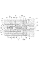
次に、図8乃至図10を用いて実施の形態における端末接続装置、及び当該端末接続装置の内部に形成された光ファイバ引留め装置の支持体固定部について説明する。
本実施の形態の端末接続装置の詳細について図8を参照して説明する。ここで端末接続装置とは、ケーブル同士を結合、分岐、中継する際に用いるもので、結線作業の後、被覆のなくなったケーブルを保護するものをいう。
本実施の形態では、ジョイントボックス200を端末接続装置の一例として説明する。 図8Aでは端末接続装置(ジョイントボックス200)の外形を投影図で示し、左右から挿入された光ケーブル50a、50bはブーツ25の中心の孔を挿通して、中央部の端末接続装置本体(ジョイントボックス本体200a)に導かれる。また、実施の形態における光ケーブル50a、50bには、一例として光ケーブル50が用いられる。
Next, the terminal connecting device according to the embodiment and the support body fixing portion of the optical fiber retaining device formed inside the terminal connecting device will be described with reference to FIGS. 8 to 10.
Details of the terminal connection device of the present embodiment will be described with reference to FIG. Here, the terminal connection device is used for connecting, branching, and relaying cables, and refers to a device that protects a cable that is no longer covered after the wiring work.
In the present embodiment, the
中央部の円柱状のカバー21の内部の端末接続装置本体で光ケーブル50a、50bの機械的、電気的、及び光学的の接続が行われる。端末接続装置本体の内部構造はほぼ左右対称と考えてよく、右半分に相当する円SP2の内部を光ケーブルの軸線を含む平面で切断した断面図を図8Bに示す。
光ケーブル50aと光ケーブル50bの接続方法と引き留め方法はほぼ同一であり、構造もほぼ同様であるのでケーブル50bに対応する部分のみを図示する。ケーブル50aに対する構造は、ほぼ図8Bの鏡像関係になると考えてよい。
The
Since the
ゴム等で形成されたブーツ25と内部のブーツインサート26は光ケーブル50a、50bを外力から保護し、接続された光ケーブルと同時にドラムに巻き取ることも可能とされている。
図8Bでは、絶縁層9を除去した光ケーブル50b(光ケーブル50)をブーツインサート26の中央に形成された挿入孔23aに挿通して引き留めた後、絶縁層9と同様の樹脂を溶融して充填し、冷却することで、光ケーブル50bと一体化したモールド23が形成されている。
光ケーブル50bは耐圧層2や抗張力層3の構成部材(分割個片2aや鋼線(抗張力線)3a等)が別途端末接続装置に引留められることで、光ケーブル本体が引き留められる。
The
In FIG. 8B, the
In the
金属製で円筒状の耐圧シリンダ28の両端に形成された端板中央の孔にアンカーディスク11が挿入されている。
耐圧シリンダ28は、その内部に収納される光ファイバ1aの接続部を水圧や屈曲等の外力から保護すると共に、接続する光ケーブル50a、50b相互の張力の伝達や給電路の電気的な接続を行っている。このため、耐圧シリンダ28は高強度の金属により形成され、その周囲が絶縁体22、モールド23で覆われ海水から絶縁している。更に金属製で円筒状のカバー21で覆い、カバー21の両端に螺合等でブーツインサート26が結合されている。
The pressure-
2本の光ケーブル50a、50bの光ファイバ1aの接続部は耐圧シリンダ28の内部に収容されるが、接続作業等のためにかなりの余裕を持たせた長さ、即ち余長が必要となる。光ファイバに伝送特性等の劣化の起こらないように収納するために、接続された光ファイバ1aを収納する図示しない余長収納体が設けられている。
余長収納体は箱状に形成され、底面が板状部材24にネジ止め等で固定されている。板状部材24は、端末接続装置の軸線方向に延びる板状に形成され、両端がそれぞれの端部側に形成されるアンカーディスク11にネジ止め等により固定されている。
また板状部材24には、後述する支持体固定部70が載置され、支持体固定部70の本体部71が板状部材24に対してネジ止め等で固定される。
The connection portion of the
The extra length storage body is formed in a box shape, and the bottom surface is fixed to the plate-shaped
Further, a support
図5で示した分割個片2aや、鋼線(抗張力線)3a等は重ならないようにアンカーディスク11のテーパ状の内周面に載置され、ほぼ同角度のテーパを有するテーパーピン13の外周面で挟持されて引き留められる。
テーパーピン13はフランジ14を介して左から押し込まれ、強固に分割個片2aや、抗張力線3aを引き留める。更にその位置が動かないようにクランプナット15で固定される。クランプナット15は、例えばクランプナット15の外周面に切られた雄ねじをアンカーディスク14の左端部に形成された雌ねじに螺合する等の手段で固定される。これにより、光ケーブル本体が端末接続装置に引き留められる。
The divided
The
光ファイバ1aは、既に、ホットメルト型接着剤31と熱収縮チューブ33で支持体32と共に固着され、光ファイバ引留め部30a及び光ファイバ保護管30bを形成している。光ファイバ引留め部30aと光ファイバ保護管30bは、光ケーブル50の端部500から軸線方向に連結して形成されている
光ファイバ引留め部30aはテーパーピン13、フランジ14、クランプナット15の中心に設けられた孔13a、14a、15aを挿通する。支持体32の先端部は耐圧シリンダ28内部に到達している。
また光ファイバ保護管30bの熱収縮チューブ33と連結されていない側の端部30cが、光ケーブル50の中空部の内部にまで挿入されている。
これにより、光ファイバ保護管30bと光ケーブル50の連結部分から光ファイバ1aが表出しなくなるため、内部に設けられた光ファイバ1aの損傷を防止することができる。
The
The
As a result, the
ここで、端末接続装置の内部に設けられた支持体固定部70について説明する。
実施の形態では、支持体固定部70により支持体32を固定することで、適切な張力を保ったまま光ファイバ1aを端末接続装置に引き留めることができる。
Here, the support
In the embodiment, by fixing the
図9A及び図9Bに示すように、支持体固定部70は、本体部71と蓋部72と頭部81と軸部82からなる複数の固定ネジ73とを有している。
本体部71は例えば円柱状に形成され、上面部に支持体32を嵌めるための固定溝74と固定ネジ73を螺合するための複数の螺合穴75とを有する。また上述の通り、本体部71は、板状部材24に対して例えばネジ止め等で固定されている。
本体部71は、上面が図8Bに示すクランプナット15の中心に設けられた孔15aと高さが略並行になるように設けられている。これにより、支持体32を略水平に固定することが可能となる。
As shown in FIGS. 9A and 9B, the support
The
The
蓋部72は、図9B及び図10Aに示すように、固定ネジ73をそれぞれ挿通させるための複数の挿通孔76を有している。これらは、蓋部72の上面に開口する状態で設けられている。また、図10Bに示すように、蓋部72の下面には、前述した複数の挿通孔76の他に、支持体32を嵌めるための固定溝77が設けられている。
As shown in FIGS. 9B and 10A, the
支持体32を本体部71の固定溝74に嵌め込み、蓋部72の固定溝77が当該嵌め込まれた支持体32に重なるように本体部71と蓋部72を重ね合わせる。そして、複数の挿通孔76にそれぞれ固定ネジ73を挿通し、螺合穴75にて螺合する。これにより、支持体32は、本体部71と蓋部72により挟持され、固定される。このように光ファイバ1aを引き留めることで、光ケーブル50a、50bに光ファイバ1aが引き込まれることを防止することができる。
The
光ファイバ1aのスラックの調整等の理由から、支持体32を固定した後に支持体32の固定位置の変更が必要となる場合がある。この場合、螺合した固定ネジ73を外すだけで支持体32の固定状態を解消することができる。そして、支持体32を図8Bにおける左右方向に自由に移動させ、再度固定ネジ73を螺合するだけで容易に支持体32を固定することが可能となる。
For reasons such as adjustment of the slack of the
ここで、図10C及び図10Dを用いて固定ネジ73の頭部81の形状について説明する。
図10Cに示すように、頭部81の形状を六角ボルトのように六角形等の多角形による形状とすることも考えられる。
ここで、海底光ケーブルを接続する端末接続装置には、設置時に外界からの様々な衝撃が想定される。よって、本体部71と蓋部72により支持体32を強固に固定する必要がある。そのため、本体部71と蓋部72を固定するための固定ネジ73の頭部81及び軸部82の径は、できる限り大きくすることが望ましい。
しかしながら、六角ボルトのように、頭部81の外周をスパナやレンチ等の器具で挟持することにより固定ネジ73を締めることとすると、器具の動作スペースを確保する必要が生じ、頭部81の径を大きくすることの妨げとなる場合があった。
Here, the shape of the
As shown in FIG. 10C, it is also conceivable that the shape of the
Here, various impacts from the outside world are expected at the time of installation of the terminal connecting device for connecting the submarine optical cable. Therefore, it is necessary to firmly fix the
However, if the fixing
そこで実施の形態においては、図10Dに示すように、固定ネジ73として六角穴付きボルトが用いられる。六角穴付きボルトには、頭頂部に軸方向に伸びる略六角柱状の溝(六角穴83)が設けられている。当該六角穴付きボルトの六角穴83に六角レンチ等の器具を挿入することで、固定ネジ73を締め付ける。これにより、固定ネジ73を締めるためのスパナやレンチ等の器具の動作スペースを確保する必要がなくなるため、頭部81の径を大きくすることができる。これにより、本体部71と蓋部72により支持体32を強固に固定することができる。
また、頭部81は角のない略円形状に形成される。これにより、さらに頭部81の径を大きくするための領域を確保することができる。
Therefore, in the embodiment, as shown in FIG. 10D, a hexagon socket head cap screw is used as the fixing
Further, the
なお、実施の形態においては、4つの固定ネジ73により本体部71と蓋部72を固定する例について説明したが、固定ネジ73の数は上記に限られることはなく、3つ以下でもよいし、5つ以上であってもよい。また、固定ネジ73には様々なネジを用いることが考えられる。例えば固定ネジ73として蝶ボルトを用いても、締めるための器具の動作スペースを確保する必要がなくなり、頭部81の径を大きくすることが可能となる。
また、組み手やジョイント金具により固定することも考えられる。
In the embodiment, the example in which the
It is also conceivable to fix it with a knot or a joint fitting.
次に、実施の形態における光ファイバ引留め装置の第1の変形例について、図11及び図12を用いて説明する。なお、以下に述べる変形例の説明において、上記で一度述べた構造と同様の部分については同一の符号を付し、説明を省略するものとする。 Next, a first modification of the optical fiber retaining device according to the embodiment will be described with reference to FIGS. 11 and 12. In the description of the modification described below, the same parts as those of the structure described above are designated by the same reference numerals, and the description thereof will be omitted.
図11、図12A、図12Bに示すように、支持体固定部70aは挟持部材71aと締め付け部材72aとで構成されている。ここで、挟持部材71aは本願請求項における第1部品の一例であり、締め付け部材72aは第2部品の一例である。
As shown in FIG. 11, FIG. 12A, and FIG. 12B, the support
挟持部材71aの端部84に形成されたフランジ84aは、図11に示すようにアンカーディスク11とネジ留め等により固定されている。また端部84の外周面の一部に切り欠き79が形成されている。切り欠き79から光ファイバ1aを引き出すことで、光ファイバ1aの接続部がある耐圧シリンダ28の内部に、光ファイバ1aが案内される。
The
挟持部材71aには凸部78が形成され、凸部78の外周面にねじ山75aが形成されている。ここで、挟持部材71aの凸部78は先端部が分割片78a、78bに分割され、分割片78a、78bの間にスリットSLが形成されている。
凸部78は先端に向かうにつれて径が小さく変位するように形成されている。
A
The
また挟持部材71aには挿通孔77aが形成され、締め付け部材72aには挿通孔77bが形成されている。挿通孔77a及び挿通孔77bには支持体32が挿通される。
締め付け部材72aの内部には、挿通孔77bの方向に向かうにつれ径が小さく変位する凹部85が形成されている。凹部85の内周面にはねじ溝75bが形成されている。
また図12Bに示すように、締め付け部材72aの端部86の外周面は六角形状とされている。これにより、スパナ等の工具により挟持部材71aのねじ山75aと締め付け部材72aのねじ溝75bとを確実に螺合することができる。
Further, the holding
Inside the tightening
Further, as shown in FIG. 12B, the outer peripheral surface of the
支持体32を挿通孔77a、挿通孔77bの順で軸線方向に挿通し、ねじ山75aとねじ溝75bとを螺合することで、挟持部材71aと締め付け部材72aとを接合する。
締め付け部材72aと接合する際の挟持部材71aの締め付けにより分割片78a、78bに圧力が加えられ、スリットSLの幅が縮小することで、挿通した支持体32を分割片78a、78bにより確実に挟持することができる。支持体固定部70aにより支持体32を固定することで、適切な張力を保ったまま光ファイバ1aを端末接続装置に引き留めることができる。
また、ねじ山75aとねじ溝75bを緩めて圧力を除去すると、締め付け部材72aによる挟持部材71aの締め付けが解除され、容易に支持体32を支持体固定部70aから取り外すことが可能である。
The
Pressure is applied to the divided
Further, when the
なお、図12Bでは挟持部材71aとしてスリットSLが1つ形成されている部材を用いているが、挟持部材71aはこれに限られるものではなく、スリットSLを例えば十字状に形成するなど、スリットSLが複数形成されていてもよい。
また、挟持部材71aの材質は樹脂製又は金属に限るものでなく、弾性体であれば、発明の趣旨を逸脱しない範囲で他の部材を採用できる。またゴム状の部材、その他の弾性体であればスリットSLは必ずしも必要ではない。
In FIG. 12B, a member having one slit SL is used as the holding
The material of the holding
次に、実施の形態における光ファイバ引留め装置の第2の変形例について、図13及び図14を用いて説明する。
図13、図14A、図14Bで示すように、支持体固定部100は挟持部材101と締め付け部材102とで構成されている。ここで、挟持部材101は本願請求項における第1部品の一例であり、締め付け部材102は第2部品の一例である。
Next, a second modification of the optical fiber retaining device according to the embodiment will be described with reference to FIGS. 13 and 14.
As shown in FIG. 13, FIG. 14A, and FIG. 14B, the support
部品としての挟持部材101は、さらに細分化された複数の部品から構成されている。具体的に挟持部材101は、固定部材103、中継部材104、挟持片105を有している。
円筒状に形成された固定部材103の端部110に形成されたフランジ110aが、図13で示すようにアンカーディスク11とネジ留め等により固定され、端部110の外周面に光ファイバ1aを案内するための切り欠き79が形成されている。
また固定部材103の他方の端部111の外周面にはねじ山103aが形成されている。
The sandwiching
A
A
中継部材104は、円筒状に形成された環状部材112と円筒状に形成され環状部材112よりも径の小さい環状部材113とが、接合板114を介して一体に形成されている。
環状部材112の内周面にはねじ溝104aが形成され、環状部材113の外周面にはねじ山104bが形成されている。ねじ溝104aとねじ山103aとを螺合することで、中継部材104と固定部材103とが接合される。
また接合板114の略中央部には、支持体32を挿通するための挿通孔104cが形成されている。
In the
A
In addition, an
挟持片105は、支持体32を挟み込むための割溝105aが形成され、端部115は先端に向かうにつれて径が小さく変位するように形成されている。挟持片105は、例えば樹脂等により形成される。
なお、挟持片105の材質は樹脂製や金属に限るものでなく、弾性体であれば、例えばゴム状の部材でもよく、他にも発明の趣旨を逸脱しない範囲で様々な部材を採用できる。
The
The material of the holding
締め付け部材102は、挟持片105の表出面を覆うようにキャップ状に形成されている。締め付け部材102の内部に形成される凹部102bは、支持体32を挿通するための挿通孔102cの方向に向かうにつれ、径が小さく変位するように形成されている。
締め付け部材102の端部116の内周面にはねじ溝102aが形成され、他端部117の外周面は六角形状とされている。締め付け部材102のねじ溝102aと中継部材104のねじ山104bとが螺合される。当該他端部の外周面を六角形状とすることで、ねじ溝102aとねじ山104bとを確実に螺合することができる。
The tightening
A
支持体32は、固定部材103、中継部材104の挿通孔104c、挟持片105の割溝105a、締め付け部材102の挿通孔102cの順に、軸線方向に挿通される。ねじ溝102aとねじ山104bとを螺合することにより支持体32を挟み込んだ挟持片105が圧迫され、割溝105aの幅が縮小することにより支持体32が支持体固定部100に挟持され固定される。支持体固定部100により支持体32を固定することで、適切な張力を保ったまま光ファイバ1aを端末接続装置に引き留めることができる。
また、ねじ溝102aとねじ山104bとを緩めて圧力を除去すると、締め付け部材102による挟持片105の締め付けが解除され、容易に支持体32を支持体固定部100から取り外すことが可能である。
The
Further, when the
上記のように部品としての挟持部材101を、固定部材103、中継部材104、挟持片105といった複数の部品に分割することで、挟持部材101を製造するにあたり加工しやすさの向上を図ることができる。また、挟持部材101が破損等した際にも、破損した一部の部品を交換するだけで修理可能となるため、修理の際の利便性の向上や修理部品調達の容易性向上を図ることができる。
By dividing the sandwiching
以上の通り、上記した実施の形態等で説明した光ファイバ引留め装置は、単数または複数本の光ファイバ1aをジェリー状充填剤とともに金属製または樹脂製の円筒状のチューブに挿通したルースチューブ型ユニットを有する光ケーブル50を接続する端末接続装置(ジョイントボックス200)の内部に設置され、光ケーブル50に挿通された光ファイバ1aを前記端末接続装置に引留める光ファイバ引留め装置であって、中空部を有する光ファイバ保護管30bが中空部を有する熱収縮チューブ33と軸線方向に連結され、中空部を有するホットメルト型接着剤31が熱収縮チューブ33の中空部に挿入され、光ファイバ1aが光ファイバ保護管30bの中空部及びホットメルト型接着剤31の中空部に挿入され、支持体32の一端が熱収縮チューブ33の中空部に挿入された状態において、ホットメルト型接着剤31が溶融され、かつ熱収縮チューブ33が収縮されることで、支持体32の一端部及び光ファイバ1aが共に一体構造として形成された光ファイバ引留め部と、支持体32の、光ファイバ引留め部30aから延出した部分を、着脱可能に固定する支持体固定部70(70a、100)と、を備えている(図8B、図11、図13)。
As described above, the optical fiber retaining device described in the above embodiments and the like is a loose tube type in which a single or a plurality of
これにより、光ファイバ引留め部30a、光ファイバ保護管30b、及び光ファイバ1aが一体構造として形成され、光ファイバ引留め部30aから延出した支持体32を支持体固定部70(70a、100)により固定することで、光ファイバ1aを間接的に端末接続装置に固定することができる。
支持体固定部70(70a、100)により、支持体32が着脱可能に固定されることで、支持体32の位置調整を適宜行うことができる。つまり、後発的に光ファイバ1aのスラックを調節することが必要になった場合であっても、支持体32の位置の調節を簡易な操作により行うことが可能となり、容易に当該スラックを調節することができる。
また容易に当該スラックを調節することができるため、作業時間の短縮が実現される。
また光ファイバ引留め部30aのうち、延出する支持体32を支持体固定部70(70a、100)で固定することで、光ファイバ1aに直接支持体固定部70(70a、100)からの応力が掛けられることを避けることができる。これにより、光ファイバ1aを引き留める際における光ファイバ1aの損傷を回避することができる。
As a result, the optical
Since the
Further, since the slack can be easily adjusted, the working time can be shortened.
Further, by fixing the extending
また光ファイバ引留め装置は、支持体固定部70(70a、100)は、端末接続装置(ジョイントボックス200)の内部に設けられた第1部品(本体部71、挟持部材71a、101)と、第1部品(本体部71、挟持部材71a、101)に対して着脱可能とされた第2部品(蓋部72、締め付け部材72a、102)と、を有し、第2部品(蓋部72、締め付け部材72a、102)を第1部品(本体部71、挟持部材71a、101)に装着することで、支持体32を挟持して固定する構成とされていることが考えられる(図8B、図11乃至図14)。
第1部品(本体部71、挟持部材71a、101)に第2部品(蓋部72、締め付け部材72a、102)を着脱するのみで支持体32を挟持し固定することができるため、支持体32の位置調整をより簡単に行うことができる。またこれにより、光ファイバ1aも容易に固定することが可能となる。
Further, in the optical fiber retaining device, the support body fixing portion 70 (70a, 100) includes a first component (
Since the
また光ファイバ引留め装置において、光ファイバ保護管30bの熱収縮チューブ33と連結されていない側の端部30cが、光ケーブル50の中空部の内部にまで挿入されていることが考えられる(図8B、図11、図13)。
これにより、光ファイバ保護管30b及び光ケーブル50の連結部分から内部に設けられた光ファイバ1aが表出しないようにすることで、光ファイバ1aの損傷を防止することができる。
Further, in the optical fiber retaining device, it is conceivable that the
Accordingly, the
また光ファイバ引留め装置は、光ファイバ引留め部30aは抗張力体90をさらに有し、ホットメルト型接着剤31が熱収縮チューブ33の中空部に挿入され、支持体32と抗張力体90とがホットメルト型接着剤31を挟んで互いに対向するように挿入された状態において、ホットメルト型接着剤31が溶融され、かつ熱収縮チューブ33が収縮されることで、支持体32の一端部、抗張力体90、及び単数又は複数本の光ファイバ1aが共に一体構造として形成されていることが考えられる(図7)。
これにより、ホットメルト型接着剤31が溶融された際に、支持体32と抗張力体90とに挟まれた光ファイバ1aは、光ファイバ引留め部30aにおける軸線方向の略中央部に配置される。従って、光ファイバ引留め部30aの外周面から不均一な圧力がかかることにより発生するマイクロベンドが生じることを防止することができる。
In the optical fiber retaining device, the optical
As a result, when the hot-
また光ファイバ引留め装置は、本体部71には1又は複数の螺合穴75が形成され、蓋部72には1又は複数の挿通孔76が形成され、挿通孔76と螺合穴75に固定ネジ73が挿入された状態で本体部71と蓋部72とを固定することが考えられる(図9)。
これにより、接着剤を用いることなしに本体部71と蓋部72を固定することができる。従って、支持体32の位置調節をする際に、本体部71と蓋部72を容易に取り外すことができ、当該位置調節が終了したらネジ止めすることで簡単に支持体32を固定することができる。つまり、光ファイバを引き留める際の作業効率を向上させることができる。
Further, in the optical fiber retainer, one or a plurality of screw holes 75 are formed in the
Thereby, the
また光ファイバ引留め装置は、固定ネジ73を六角穴付きボルトとすることが考えられる(図9、図10D)。従って、外的要因によって固定ネジ73が後発的に弛むことを防止することができる。
また光ファイバ引留め装置は、固定ネジ73の頭部の外周が略円形状に形成されていることが考えられる(図9、図10D)。これにより、固定ネジ73を緩める際に用いるために必要な蓋部72における用具の作業スペースを減らすことができる。従って、支持体固定部70における固定する固定ネジ73の大きさを十分に確保することができる。よって、支持体32を支持体固定部70により、一層強固に固定することができる。
Further, in the optical fiber retaining device, the fixing
Further, in the optical fiber retaining device, it is considered that the outer periphery of the head of the fixing
また光ファイバ引留め装置は、本体部71と蓋部72とを固定する際に、本体部71と蓋部72との接触面に棒状の支持体32を固定するための溝74、溝77を有することが考えられる(図9B、図10B)。これにより、支持体32を固定する際に、支持体固定部70における当該支持体32の位置決めを容易に行うことができる。
In addition, the optical fiber retaining device includes the
本発明の光ファイバ引留め装置は海底光ケーブルに適用した例を説明したが、本発明の光ファイバの引留め装置は海底ケーブルのみでなく、陸上で使用される光ケーブルにも広く応用可能である。 Although the optical fiber retaining device of the present invention has been described as applied to a submarine optical cable, the optical fiber retaining device of the present invention can be widely applied not only to a submarine cable but also to an optical cable used on land.
実施の形態では、光ケーブル50a、50bを、一例として図5に示す光ケーブル50として説明したが、ルースチューブ機能を耐圧層や耐圧殻で兼用したケーブルにも適応することが可能である(例えば、特開2004−184760号公報の図7乃至図10、図12参照)。
In the embodiment, the
最後に、上述した実施の形態における当該帯の説明は本発明の一例であり、本発明は上述の実施の形態に限定されることはない。このため、上述した各実施の形態以外であっても、本発明に係る技術的思想を逸脱しない範囲であれば、設計等に応じて種々の変更が可能であることはもちろんである。 Finally, the description of the band in the above-described embodiment is an example of the present invention, and the present invention is not limited to the above-described embodiment. Therefore, it goes without saying that various modifications other than the above-described embodiments can be made according to the design and the like as long as they do not deviate from the technical idea of the present invention.
1a…光ファイバ、30a…光ファイバ引留め部、30b…光ファイバ保護管、31…ホットメルト型接着剤、32…支持体、33…熱収縮チューブ、50…光ケーブル、70…支持体固定部、200…ジョイントボックス 1a... Optical fiber, 30a... Optical fiber retaining section, 30b... Optical fiber protection tube, 31... Hot melt adhesive, 32... Support, 33... Heat shrink tube, 50... Optical cable, 70... Support fixing section, 200... Joint box
Claims (4)
中空部を有する熱収縮チューブと、前記光ケーブルとは別体に形成され中空部を有し前記熱収縮チューブと同等の熱収縮が生じない光ファイバ保護管とが軸線方向に連結され、中空部を有するホットメルト型接着剤が前記熱収縮チューブの中空部に挿入され、前記光ファイバが前記光ファイバ保護管の中空部及び前記ホットメルト型接着剤の中空部に挿入され、支持体の一端が前記熱収縮チューブの中空部に挿入された状態において、前記ホットメルト型接着剤が溶融され、かつ前記熱収縮チューブが収縮されることで、前記支持体の一端部及び前記光ファイバが共に一体構造として形成された光ファイバ引留め部と、
前記支持体の、前記光ファイバ引留め部から延出した部分を、着脱可能に固定する支持体固定部と、を備える
光ファイバ引留め装置。 It is installed inside a terminal connection device for connecting an optical cable having a loose tube type unit in which a single or a plurality of optical fibers are inserted into a cylindrical tube made of metal or resin together with a jelly-like filler, and is inserted into the optical cable. An optical fiber retaining device for retaining the optical fiber in the terminal connecting device,
A heat-shrinkable tube having a hollow portion, and an optical fiber protection tube that is formed separately from the optical cable and has a hollow portion that does not cause the same heat shrinkage as the heat-shrinkable tube are axially connected, and the hollow portion is The hot melt adhesive having is inserted into the hollow portion of the heat shrinkable tube, the optical fiber is inserted into the hollow portion of the optical fiber protection tube and the hollow portion of the hot melt adhesive, one end of the support is the In the state of being inserted into the hollow portion of the heat shrink tube, the hot melt adhesive is melted and the heat shrink tube is shrunk, so that one end of the support and the optical fiber are integrally structured. The formed optical fiber retaining portion,
An optical fiber retaining device comprising: a support fixing portion that detachably fixes a portion of the support extending from the optical fiber retaining portion.
前記第2部品を前記第1部品に装着することで、前記支持体を挟持して固定する構成とされている
請求項1に記載の光ファイバ引留め装置。 The support body fixing portion has a first component provided inside the terminal connection device, and a second component detachable from the first component,
The optical fiber retaining device according to claim 1, wherein the support is sandwiched and fixed by mounting the second component on the first component.
請求項1又は請求項2に記載の光ファイバ引留め装置。 The optical fiber retaining device according to claim 1 or 2, wherein an end portion of the optical fiber protection tube on the side not connected to the heat shrink tube is inserted even inside the hollow portion of the optical cable.
前記ホットメルト型接着剤が前記熱収縮チューブの中空部に挿入され、前記支持体と前記抗張力体とが前記ホットメルト型接着剤を挟んで互いに対向するように挿入された状態において、前記ホットメルト型接着剤が溶融され、かつ前記熱収縮チューブが収縮されることで、前記支持体の一端部、前記抗張力体、及び前記光ファイバが共に一体構造として形成されている
請求項1乃至請求項3の何れかに記載の光ファイバ引留め装置。 The optical fiber retaining portion further has a strength member,
The hot melt adhesive is inserted into the hollow part of the heat shrinkable tube, and the hot melt is inserted in a state where the support and the tensile strength member are inserted so as to face each other with the hot melt adhesive interposed therebetween. The mold adhesive is melted and the heat-shrinkable tube is shrunk, so that one end of the support, the tensile strength member, and the optical fiber are integrally formed as a unitary structure. The optical fiber retaining device according to any one of 1.
Priority Applications (1)
| Application Number | Priority Date | Filing Date | Title |
|---|---|---|---|
| JP2018165210A JP6720254B2 (en) | 2018-09-04 | 2018-09-04 | Optical fiber retainer |
Applications Claiming Priority (1)
| Application Number | Priority Date | Filing Date | Title |
|---|---|---|---|
| JP2018165210A JP6720254B2 (en) | 2018-09-04 | 2018-09-04 | Optical fiber retainer |
Publications (2)
| Publication Number | Publication Date |
|---|---|
| JP2020038285A JP2020038285A (en) | 2020-03-12 |
| JP6720254B2 true JP6720254B2 (en) | 2020-07-08 |
Family
ID=69737892
Family Applications (1)
| Application Number | Title | Priority Date | Filing Date |
|---|---|---|---|
| JP2018165210A Active JP6720254B2 (en) | 2018-09-04 | 2018-09-04 | Optical fiber retainer |
Country Status (1)
| Country | Link |
|---|---|
| JP (1) | JP6720254B2 (en) |
-
2018
- 2018-09-04 JP JP2018165210A patent/JP6720254B2/en active Active
Also Published As
| Publication number | Publication date |
|---|---|
| JP2020038285A (en) | 2020-03-12 |
Similar Documents
| Publication | Publication Date | Title |
|---|---|---|
| JP5806305B2 (en) | Optical fiber connector and assembly method thereof | |
| JP2868828B2 (en) | Optical fiber cable splicer | |
| AU642670B2 (en) | Cable joint | |
| US8254743B2 (en) | Optical fiber cable holder, fusion splicer including the holder, and fusion splicing method using the holder | |
| US6728451B2 (en) | Optical fiber holding structure and method of making same | |
| GB2030723A (en) | Fibre-optic Cable Joints | |
| JPS6073506A (en) | Method and apparatus for repairing or connecting optical fiber cable | |
| SK280421B6 (en) | Drawing head for optical cables | |
| JP5233859B2 (en) | Optical fiber reinforcing method | |
| JPS60169815A (en) | Connection end part of cable with optical fiber | |
| US4348076A (en) | Fibre-optic cable joints | |
| JP3867273B2 (en) | Optical fiber retainer | |
| JP6720254B2 (en) | Optical fiber retainer | |
| JP5619700B2 (en) | Folder, optical composite power cable, optical cable connection method | |
| JP3876273B2 (en) | Optical fiber retainer | |
| JP5846386B2 (en) | Reinforcing sleeve, optical cable connection method | |
| JP2017068220A (en) | Connection structure and connection method of metal tube covered optical fiber cable | |
| GB2274175A (en) | Submarine optical cable joint | |
| KR100533219B1 (en) | Optical fiber joint box for submarine telecommunication cable | |
| JP4598284B2 (en) | Submarine optical cable retainer | |
| JP2019159141A (en) | Connection structure and method for manufacturing connection structure | |
| JP6626136B2 (en) | Optical fiber cable adapter and closure sealing method | |
| JPS6151767B2 (en) | ||
| JP2002244001A (en) | Anchoring device for submarine optical fiber cable | |
| CN116364347A (en) | Photoelectric hybrid cable and production process thereof |
Legal Events
| Date | Code | Title | Description |
|---|---|---|---|
| A621 | Written request for application examination |
Free format text: JAPANESE INTERMEDIATE CODE: A621 Effective date: 20181108 |
|
| A131 | Notification of reasons for refusal |
Free format text: JAPANESE INTERMEDIATE CODE: A131 Effective date: 20191217 |
|
| A521 | Request for written amendment filed |
Free format text: JAPANESE INTERMEDIATE CODE: A523 Effective date: 20200207 |
|
| TRDD | Decision of grant or rejection written | ||
| A01 | Written decision to grant a patent or to grant a registration (utility model) |
Free format text: JAPANESE INTERMEDIATE CODE: A01 Effective date: 20200609 |
|
| A61 | First payment of annual fees (during grant procedure) |
Free format text: JAPANESE INTERMEDIATE CODE: A61 Effective date: 20200617 |
|
| R150 | Certificate of patent or registration of utility model |
Ref document number: 6720254 Country of ref document: JP Free format text: JAPANESE INTERMEDIATE CODE: R150 |