JP6711769B2 - 2D/3D holographic display system - Google Patents
2D/3D holographic display system Download PDFInfo
- Publication number
- JP6711769B2 JP6711769B2 JP2017039851A JP2017039851A JP6711769B2 JP 6711769 B2 JP6711769 B2 JP 6711769B2 JP 2017039851 A JP2017039851 A JP 2017039851A JP 2017039851 A JP2017039851 A JP 2017039851A JP 6711769 B2 JP6711769 B2 JP 6711769B2
- Authority
- JP
- Japan
- Prior art keywords
- image
- data
- lens
- holographic
- dimensional
- Prior art date
- Legal status (The legal status is an assumption and is not a legal conclusion. Google has not performed a legal analysis and makes no representation as to the accuracy of the status listed.)
- Active
Links
Images


Classifications
-
- G—PHYSICS
- G02—OPTICS
- G02B—OPTICAL ELEMENTS, SYSTEMS OR APPARATUS
- G02B27/00—Optical systems or apparatus not provided for by any of the groups G02B1/00 - G02B26/00, G02B30/00
- G02B27/01—Head-up displays
- G02B27/0101—Head-up displays characterised by optical features
- G02B27/0103—Head-up displays characterised by optical features comprising holographic elements
-
- G—PHYSICS
- G02—OPTICS
- G02B—OPTICAL ELEMENTS, SYSTEMS OR APPARATUS
- G02B30/00—Optical systems or apparatus for producing three-dimensional [3D] effects, e.g. stereoscopic images
- G02B30/20—Optical systems or apparatus for producing three-dimensional [3D] effects, e.g. stereoscopic images by providing first and second parallax images to an observer's left and right eyes
- G02B30/26—Optical systems or apparatus for producing three-dimensional [3D] effects, e.g. stereoscopic images by providing first and second parallax images to an observer's left and right eyes of the autostereoscopic type
-
- G—PHYSICS
- G03—PHOTOGRAPHY; CINEMATOGRAPHY; ANALOGOUS TECHNIQUES USING WAVES OTHER THAN OPTICAL WAVES; ELECTROGRAPHY; HOLOGRAPHY
- G03H—HOLOGRAPHIC PROCESSES OR APPARATUS
- G03H1/00—Holographic processes or apparatus using light, infrared or ultraviolet waves for obtaining holograms or for obtaining an image from them; Details peculiar thereto
- G03H1/04—Processes or apparatus for producing holograms
- G03H1/08—Synthesising holograms, i.e. holograms synthesized from objects or objects from holograms
-
- G—PHYSICS
- G03—PHOTOGRAPHY; CINEMATOGRAPHY; ANALOGOUS TECHNIQUES USING WAVES OTHER THAN OPTICAL WAVES; ELECTROGRAPHY; HOLOGRAPHY
- G03H—HOLOGRAPHIC PROCESSES OR APPARATUS
- G03H1/00—Holographic processes or apparatus using light, infrared or ultraviolet waves for obtaining holograms or for obtaining an image from them; Details peculiar thereto
- G03H1/04—Processes or apparatus for producing holograms
- G03H1/08—Synthesising holograms, i.e. holograms synthesized from objects or objects from holograms
- G03H1/0891—Processes or apparatus adapted to convert digital holographic data into a hologram
-
- G—PHYSICS
- G03—PHOTOGRAPHY; CINEMATOGRAPHY; ANALOGOUS TECHNIQUES USING WAVES OTHER THAN OPTICAL WAVES; ELECTROGRAPHY; HOLOGRAPHY
- G03H—HOLOGRAPHIC PROCESSES OR APPARATUS
- G03H1/00—Holographic processes or apparatus using light, infrared or ultraviolet waves for obtaining holograms or for obtaining an image from them; Details peculiar thereto
- G03H1/22—Processes or apparatus for obtaining an optical image from holograms
-
- G—PHYSICS
- G03—PHOTOGRAPHY; CINEMATOGRAPHY; ANALOGOUS TECHNIQUES USING WAVES OTHER THAN OPTICAL WAVES; ELECTROGRAPHY; HOLOGRAPHY
- G03H—HOLOGRAPHIC PROCESSES OR APPARATUS
- G03H1/00—Holographic processes or apparatus using light, infrared or ultraviolet waves for obtaining holograms or for obtaining an image from them; Details peculiar thereto
- G03H1/22—Processes or apparatus for obtaining an optical image from holograms
- G03H1/2202—Reconstruction geometries or arrangements
- G03H1/2205—Reconstruction geometries or arrangements using downstream optical component
-
- G—PHYSICS
- G03—PHOTOGRAPHY; CINEMATOGRAPHY; ANALOGOUS TECHNIQUES USING WAVES OTHER THAN OPTICAL WAVES; ELECTROGRAPHY; HOLOGRAPHY
- G03H—HOLOGRAPHIC PROCESSES OR APPARATUS
- G03H1/00—Holographic processes or apparatus using light, infrared or ultraviolet waves for obtaining holograms or for obtaining an image from them; Details peculiar thereto
- G03H1/22—Processes or apparatus for obtaining an optical image from holograms
- G03H1/2249—Holobject properties
-
- G—PHYSICS
- G03—PHOTOGRAPHY; CINEMATOGRAPHY; ANALOGOUS TECHNIQUES USING WAVES OTHER THAN OPTICAL WAVES; ELECTROGRAPHY; HOLOGRAPHY
- G03H—HOLOGRAPHIC PROCESSES OR APPARATUS
- G03H1/00—Holographic processes or apparatus using light, infrared or ultraviolet waves for obtaining holograms or for obtaining an image from them; Details peculiar thereto
- G03H1/22—Processes or apparatus for obtaining an optical image from holograms
- G03H1/2294—Addressing the hologram to an active spatial light modulator
-
- G—PHYSICS
- G03—PHOTOGRAPHY; CINEMATOGRAPHY; ANALOGOUS TECHNIQUES USING WAVES OTHER THAN OPTICAL WAVES; ELECTROGRAPHY; HOLOGRAPHY
- G03H—HOLOGRAPHIC PROCESSES OR APPARATUS
- G03H1/00—Holographic processes or apparatus using light, infrared or ultraviolet waves for obtaining holograms or for obtaining an image from them; Details peculiar thereto
- G03H1/26—Processes or apparatus specially adapted to produce multiple sub- holograms or to obtain images from them, e.g. multicolour technique
-
- G—PHYSICS
- G02—OPTICS
- G02B—OPTICAL ELEMENTS, SYSTEMS OR APPARATUS
- G02B27/00—Optical systems or apparatus not provided for by any of the groups G02B1/00 - G02B26/00, G02B30/00
- G02B27/01—Head-up displays
- G02B27/0101—Head-up displays characterised by optical features
- G02B2027/0127—Head-up displays characterised by optical features comprising devices increasing the depth of field
-
- G—PHYSICS
- G03—PHOTOGRAPHY; CINEMATOGRAPHY; ANALOGOUS TECHNIQUES USING WAVES OTHER THAN OPTICAL WAVES; ELECTROGRAPHY; HOLOGRAPHY
- G03H—HOLOGRAPHIC PROCESSES OR APPARATUS
- G03H1/00—Holographic processes or apparatus using light, infrared or ultraviolet waves for obtaining holograms or for obtaining an image from them; Details peculiar thereto
- G03H1/04—Processes or apparatus for producing holograms
- G03H1/08—Synthesising holograms, i.e. holograms synthesized from objects or objects from holograms
- G03H1/0808—Methods of numerical synthesis, e.g. coherent ray tracing [CRT], diffraction specific
-
- G—PHYSICS
- G03—PHOTOGRAPHY; CINEMATOGRAPHY; ANALOGOUS TECHNIQUES USING WAVES OTHER THAN OPTICAL WAVES; ELECTROGRAPHY; HOLOGRAPHY
- G03H—HOLOGRAPHIC PROCESSES OR APPARATUS
- G03H1/00—Holographic processes or apparatus using light, infrared or ultraviolet waves for obtaining holograms or for obtaining an image from them; Details peculiar thereto
- G03H1/02—Details of features involved during the holographic process; Replication of holograms without interference recording
- G03H2001/0208—Individual components other than the hologram
- G03H2001/0224—Active addressable light modulator, i.e. Spatial Light Modulator [SLM]
-
- G—PHYSICS
- G03—PHOTOGRAPHY; CINEMATOGRAPHY; ANALOGOUS TECHNIQUES USING WAVES OTHER THAN OPTICAL WAVES; ELECTROGRAPHY; HOLOGRAPHY
- G03H—HOLOGRAPHIC PROCESSES OR APPARATUS
- G03H1/00—Holographic processes or apparatus using light, infrared or ultraviolet waves for obtaining holograms or for obtaining an image from them; Details peculiar thereto
- G03H1/04—Processes or apparatus for producing holograms
- G03H1/08—Synthesising holograms, i.e. holograms synthesized from objects or objects from holograms
- G03H1/0841—Encoding method mapping the synthesized field into a restricted set of values representative of the modulator parameters, e.g. detour phase coding
- G03H2001/085—Kinoform, i.e. phase only encoding wherein the computed field is processed into a distribution of phase differences
-
- G—PHYSICS
- G03—PHOTOGRAPHY; CINEMATOGRAPHY; ANALOGOUS TECHNIQUES USING WAVES OTHER THAN OPTICAL WAVES; ELECTROGRAPHY; HOLOGRAPHY
- G03H—HOLOGRAPHIC PROCESSES OR APPARATUS
- G03H1/00—Holographic processes or apparatus using light, infrared or ultraviolet waves for obtaining holograms or for obtaining an image from them; Details peculiar thereto
- G03H1/22—Processes or apparatus for obtaining an optical image from holograms
- G03H1/2249—Holobject properties
- G03H2001/2252—Location of the holobject
- G03H2001/2255—Holobject out of Fourier or hologram planes
-
- G—PHYSICS
- G03—PHOTOGRAPHY; CINEMATOGRAPHY; ANALOGOUS TECHNIQUES USING WAVES OTHER THAN OPTICAL WAVES; ELECTROGRAPHY; HOLOGRAPHY
- G03H—HOLOGRAPHIC PROCESSES OR APPARATUS
- G03H1/00—Holographic processes or apparatus using light, infrared or ultraviolet waves for obtaining holograms or for obtaining an image from them; Details peculiar thereto
- G03H1/22—Processes or apparatus for obtaining an optical image from holograms
- G03H1/2294—Addressing the hologram to an active spatial light modulator
- G03H2001/2297—Addressing the hologram to an active spatial light modulator using frame sequential, e.g. for reducing speckle noise
-
- G—PHYSICS
- G03—PHOTOGRAPHY; CINEMATOGRAPHY; ANALOGOUS TECHNIQUES USING WAVES OTHER THAN OPTICAL WAVES; ELECTROGRAPHY; HOLOGRAPHY
- G03H—HOLOGRAPHIC PROCESSES OR APPARATUS
- G03H2210/00—Object characteristics
- G03H2210/20—2D object
-
- G—PHYSICS
- G03—PHOTOGRAPHY; CINEMATOGRAPHY; ANALOGOUS TECHNIQUES USING WAVES OTHER THAN OPTICAL WAVES; ELECTROGRAPHY; HOLOGRAPHY
- G03H—HOLOGRAPHIC PROCESSES OR APPARATUS
- G03H2210/00—Object characteristics
- G03H2210/30—3D object
-
- G—PHYSICS
- G03—PHOTOGRAPHY; CINEMATOGRAPHY; ANALOGOUS TECHNIQUES USING WAVES OTHER THAN OPTICAL WAVES; ELECTROGRAPHY; HOLOGRAPHY
- G03H—HOLOGRAPHIC PROCESSES OR APPARATUS
- G03H2210/00—Object characteristics
- G03H2210/30—3D object
- G03H2210/33—3D/2D, i.e. the object is formed of stratified 2D planes, e.g. tomographic data
-
- G—PHYSICS
- G03—PHOTOGRAPHY; CINEMATOGRAPHY; ANALOGOUS TECHNIQUES USING WAVES OTHER THAN OPTICAL WAVES; ELECTROGRAPHY; HOLOGRAPHY
- G03H—HOLOGRAPHIC PROCESSES OR APPARATUS
- G03H2210/00—Object characteristics
- G03H2210/40—Synthetic representation, i.e. digital or optical object decomposition
- G03H2210/45—Representation of the decomposed object
- G03H2210/454—Representation of the decomposed object into planes
-
- G—PHYSICS
- G03—PHOTOGRAPHY; CINEMATOGRAPHY; ANALOGOUS TECHNIQUES USING WAVES OTHER THAN OPTICAL WAVES; ELECTROGRAPHY; HOLOGRAPHY
- G03H—HOLOGRAPHIC PROCESSES OR APPARATUS
- G03H2225/00—Active addressable light modulator
- G03H2225/20—Nature, e.g. e-beam addressed
- G03H2225/22—Electrically addressed SLM [EA-SLM]
-
- G—PHYSICS
- G03—PHOTOGRAPHY; CINEMATOGRAPHY; ANALOGOUS TECHNIQUES USING WAVES OTHER THAN OPTICAL WAVES; ELECTROGRAPHY; HOLOGRAPHY
- G03H—HOLOGRAPHIC PROCESSES OR APPARATUS
- G03H2225/00—Active addressable light modulator
- G03H2225/30—Modulation
- G03H2225/32—Phase only
-
- G—PHYSICS
- G03—PHOTOGRAPHY; CINEMATOGRAPHY; ANALOGOUS TECHNIQUES USING WAVES OTHER THAN OPTICAL WAVES; ELECTROGRAPHY; HOLOGRAPHY
- G03H—HOLOGRAPHIC PROCESSES OR APPARATUS
- G03H2225/00—Active addressable light modulator
- G03H2225/52—Reflective modulator
Landscapes
- Physics & Mathematics (AREA)
- General Physics & Mathematics (AREA)
- Optics & Photonics (AREA)
- Holo Graphy (AREA)
- Diffracting Gratings Or Hologram Optical Elements (AREA)
- Transforming Electric Information Into Light Information (AREA)
Description
本発明は、表示システムおよび画像を表示する方法に関する。実施形態は、仮想画像表示のシステムおよび方法に関し、いくつかの実施形態は、ヘッドアップ・ディスプレイ・システムに関する。 The present invention relates to display systems and methods for displaying images. Embodiments relate to virtual image display systems and methods, and some embodiments relate to head-up display systems.
物体から散乱する光は、振幅と位相両方の情報を含む。この振幅および位相の情報は、例えば、干渉じまを含むホログラムを形成する周知の干渉法によって感光板上に取り込むことができる。ホログラムは、ホログラムを適切な光で照明することにより、元の物体を表す画像、すなわちホログラフィック再構成を形成するように再構成され得る。 Light scattered from an object contains both amplitude and phase information. This amplitude and phase information can be captured on the photosensitive plate by, for example, a well-known interferometry method for forming a hologram containing interference fringes. The hologram can be reconstructed to form an image, or holographic reconstruction, of the original object by illuminating the hologram with appropriate light.
コンピュータ生成ホログラフィは、フーリエ法を使用して干渉プロセスを数値的にシミュレートし得る。 Computer generated holography can numerically simulate the interfering process using the Fourier method.
ホログラフィ法を2次元画像プロジェクタにおいて使用することが提案されている。 It has been proposed to use the holographic method in two-dimensional image projectors.
図1を参照すると、フーリエレンズ(120)を介して、この場合はおおむね平面状の波面としての空間光変調器(140)上へ光を当てる光源100が示されている。空間光変調器は、反射し、多数の位相変調素子のアレイからなるものである。光は空間光変調器によって反射され、2つの部分、すなわち、(ゼロ次と呼ばれる)第1の鏡面反射される部分と、位相変調素子によって空間的に変化する位相の波面を形成するように変調されている第2の部分とからなる。空間光変調器による反射のために、すべての光はおおむね光源(100)の方へ反射され、そこで光は、系の軸に対して45°に配置された開口(160)を有する反射鏡に当たる。光の画像部分のすべてが反射鏡により、系の軸に対しておおむね平行な画面(180)へ向けて反射される。フーリエレンズ(120)の作用のために、画面(180)に当たる光は、位相変調素子へ適用された情報が由来する画像の再構成である実像を形成する。
Referring to FIG. 1, there is shown a
実施形態は、ホログラフィック再構成の仮想画像を形成し、空間における仮想画像の適応位置制御を提供するための改善された2次元リアルタイムプロジェクタに関する。そして、さらに好ましい実施形態は、再構成の空間的フィルタリングを可能にする。 Embodiments relate to an improved two-dimensional real-time projector for forming a holographically reconstructed virtual image and providing adaptive position control of the virtual image in space. And a further preferred embodiment enables spatial filtering of the reconstruction.
本発明の態様は添付の独立請求項に定義されている。 Aspects of the invention are defined in the attached independent claims.
要約すると、空間光変調器(SLM)が、プロジェクタを形成するために、SLMを正しく照明することによって再構成することができる所望の画像の位相のみのフーリエ変換を集合的に表す位相変調素子のアレイを形成する。位相のみの分布はホログラムと呼ばれ得る。画像は、ホログラフィック再構成として説明され得る。SLMの素子を画素と呼んでもよい。 In summary, spatial light modulators (SLMs) are phase modulation elements that collectively represent the phase-only Fourier transform of the desired image that can be reconstructed by properly illuminating the SLM to form a projector. Form an array. The phase-only distribution can be called a hologram. The image may be described as a holographic reconstruction. The elements of the SLM may be called pixels.
ホログラフィック再構成は、仮想画像を形成するための光学目視システムによって画像化される。発明者は、ホログラムに可変レンズ法(variable lensing)データを提供することにより、目視者に対する仮想画像の位置を変更することができることを認めている。これにより、表示システムに「深さ」が提供され、仮想画像を目視者から異なる距離において提示させて、擬似3次元システムをリアルタイムで提供することができる。特に、発明者は、中間再構成を形成することにより、空間的フィルタリングが、ホログラムによって生成されるより高い回折次数を除去するように行われ得ることを認めている。これにより、特に、ヘッドアップディスプレイといったリアルタイム用途のための改善された目視システムが生じる。 The holographic reconstruction is imaged by an optical viewing system to form a virtual image. The inventor recognizes that the position of the virtual image with respect to the viewer can be changed by providing the hologram with variable lensing data. This provides "depth" to the display system, allowing virtual images to be presented at different distances from the viewer, providing a pseudo-three-dimensional system in real time. In particular, the inventor recognizes that by forming an intermediate reconstruction, spatial filtering can be done to remove the higher diffraction orders produced by the hologram. This results in an improved viewing system, especially for real-time applications such as head-up displays.
次に、本発明の実施形態を、添付の図面に合わせて説明する。 Next, an embodiment of the present invention will be described with reference to the accompanying drawings.
許容できる品質のホログラフィック再構成を生じさせることができるホログラムを生成するには位相情報だけで十分であることがわかっている。すなわち、ホログラム中の振幅情報は廃棄することができる。これにより必要なレーザ光源の出力を低減することができるが、これには他の利点もある。したがって、フーリエベースのコンピュータ生成ホログラフィ法は、位相情報だけを使用して策定されている。 It has been found that the phase information alone is sufficient to produce holograms that can produce holographic reconstructions of acceptable quality. That is, the amplitude information in the hologram can be discarded. This can reduce the required laser source power, but this has other advantages. Therefore, Fourier-based computer-generated holography methods have been developed using only phase information.
ホログラムによって再構成される画像は、ホログラムのフーリエ変換によって与えられる。したがって、ホログラムは物体のフーリエ変換を表す位相のみのパターンであるのに対して、再構成される画像(またはホログラフィック再構成)は、振幅と位相両方の情報を含み得る。 The image reconstructed by the hologram is given by the Fourier transform of the hologram. Thus, a hologram is a phase-only pattern that represents the Fourier transform of an object, whereas a reconstructed image (or holographic reconstruction) may contain both amplitude and phase information.
Gerchberg−Saxton(ジャーチバーグ・ザクストン)法は、振幅情報だけを含む入力画像データから位相のみのホログラムを計算するための反復アルゴリズムの一例である。このアルゴリズムは、ランダム位相パターンから開始し、これを振幅データと結合して複合データを形成する。複合データに対して離散フーリエ変換が行われ、結果として得られるデータセットは、振幅と位相からなるフーリエ成分である。振幅情報は均一な値に設定され、位相は、利用可能な位相値にマッチするように量子化される。次いで逆離散フーリエ変換が行われる。その結果は別の複合データセットであり、その場合、振幅情報がターゲット画像で上書きされ、プロセスが繰り返される。したがって、Gerchberg−Saxtonアルゴリズムは、空間領域とフーリエ(スペクトル)領域との間でデータセット(振幅および位相)を繰り返し変換する間に、空間制約条件およびスペクトル制約条件を反復して適用する。 The Gerchberg-Saxton method is an example of an iterative algorithm for calculating a phase-only hologram from input image data that includes only amplitude information. The algorithm starts with a random phase pattern and combines it with amplitude data to form composite data. The discrete Fourier transform is performed on the composite data and the resulting data set is a Fourier component consisting of amplitude and phase. The amplitude information is set to a uniform value and the phase is quantized to match the available phase values. Then the inverse discrete Fourier transform is performed. The result is another composite data set, in which case the amplitude information is overwritten with the target image and the process is repeated. Thus, the Gerchberg-Saxton algorithm iteratively applies spatial and spectral constraints while iteratively transforming a dataset (amplitude and phase) between the spatial and Fourier (spectral) domains.
Gerchberg−Saxtonアルゴリズムおよびその派生アルゴリズムは、多くの場合、直接バイナリ・サーチ・アルゴリズムといった「非フーリエ変換」アルゴリズムよりずっと高速である。Gerchberg−Saxtonに基づく修正アルゴリズムが策定されている。例えば、参照により本明細書に組み込まれる同時係属の公開PCT出願WO2007/131650を参照されたい。 The Gerchberg-Saxton algorithm and its derivatives are often much faster than "non-Fourier transform" algorithms such as the direct binary search algorithm. A modified algorithm based on Gerchberg-Saxton has been developed. See, for example, co-pending published PCT application WO2007/131650, which is incorporated herein by reference.
これらの改良型の技法は、2次元ビデオ投影が実現されるのに十分な速度でホログラムを計算することができる。本明細書で説明する実施形態は、そのような修正Gerchberg−Saxtonアルゴリズムを使用して計算されるコンピュータ生成ホログラムを使用した2次元ビデオ投影に関するものである。 These improved techniques are capable of computing holograms fast enough to achieve two-dimensional video projection. The embodiments described herein relate to two-dimensional video projection using computer generated holograms calculated using such a modified Gerchberg-Saxton algorithm.
ホログラフィを用いて生成される2次元ビデオ画像は、特に、鮮明度および効率の点で、従来の投影2次元画像に優る著しい利点を有することが知られている。しかし、現在のホログラム生成アルゴリズムの計算およびハードウェアが複雑であるため、そのリアルタイム用途での使用が妨げられている。最近、これらの問題が解決された。例えば、参照により本明細書に組み込まれる公開PCT出願WO2005/059881を参照されたい。 Two-dimensional video images produced using holography are known to have significant advantages over traditional projected two-dimensional images, especially in terms of sharpness and efficiency. However, the computational complexity and hardware of current hologram generation algorithms has hindered their use in real-time applications. Recently these problems have been resolved. See, for example, published PCT application WO 2005/059881 which is incorporated herein by reference.
位相のみのホログラフィックデータを表示するには、位相変調デバイスが必要である。これらのデバイスは、振幅を変調しないため、一般に光透過性である。したがって、例えば光が吸収により失われることがない。これには、すべての再構成光がホログラフィック再構成の作成に使用されるという大きな利点がある。これは言い換えると、よりエネルギー効率のよい表示システムということになる。 A phase modulation device is required to display phase-only holographic data. These devices are generally light transmissive because they do not modulate amplitude. Therefore, for example, light is not lost by absorption. This has the great advantage that all reconstructed light is used to create the holographic reconstruction. In other words, this is a more energy efficient display system.
位相変調デバイスは画素化されてもよく、各画素は回折素子として働くことになる。各画素からの回折パターンは、再生場(replay field)と呼ばれる画面における複雑な干渉パターンを生じさせる。この複雑な関係のために、ホログラム上の各画素は、再構成される画像の複数の部分に寄与する。 The phase modulation device may be pixellated, each pixel will act as a diffractive element. The diffraction pattern from each pixel gives rise to a complex interference pattern on the screen called the replay field. Because of this complex relationship, each pixel on the hologram contributes to multiple parts of the reconstructed image.
位相変調デバイスの一例が空間光変調器(SLM)である。典型的には、SLMは、アドレス指定可能な位相変調素子のフィールドを有する。あるSLMでは位相変調素子は素子の線形または1次元アレイであり、別のSLMでは2次元アレイが設けられる。簡潔にするために、多くのSLMは、全体として四角い位相変調素子の規則的な2次元アレイを有する。しかし、位相変調素子が同様のサイズおよび形状を有する必要はない。 One example of a phase modulation device is a spatial light modulator (SLM). Typically, SLMs have a field of addressable phase modulators. In one SLM, the phase modulation element is a linear or one-dimensional array of elements, in another SLM a two-dimensional array is provided. For simplicity, many SLMs have a regular two-dimensional array of generally square phase modulation elements. However, it is not necessary that the phase modulating elements have similar size and shape.
図2に、本開示による、LCOSといった反射SLMを使用した再生場位置におけるホログラフィック再構成の生成の一例を示す。 FIG. 2 illustrates an example of generating a holographic reconstruction at a playback field position using a reflective SLM such as LCOS according to the present disclosure.
光源(210)、例えばレーザやレーザダイオードなどが、コリメーティングレンズ(211)を介してSLM(240)を照明するように配置されている。コリメーティングレンズは、光のおおむね平面状の波面をSLMに入射させる。波面の方向はわずかにオフノーマルである(すなわち、透明層の面に対して直角から2、3度ずれている)。この配置は、光源からの光がSLMの鏡面反射する背面から反射され、位相変調層と相互作用して射出波面(exiting wavefront)(212)を形成するというものである。射出波面(212)は、その焦点が画面(225)のところにあるフーリエ変換レンズ(220)を含む光学系へ当てられる。 A light source (210), such as a laser or laser diode, is arranged to illuminate the SLM (240) via a collimating lens (211). The collimating lens causes the generally planar wavefront of light to enter the SLM. The wavefront direction is slightly off-normal (ie, offset by a few degrees from the right angle to the plane of the transparent layer). This arrangement is such that the light from the light source is reflected from the SLM's specular back surface and interacts with the phase modulation layer to form an exiting wavefront (212). The exit wavefront (212) is focused on an optical system that includes a Fourier transform lens (220) whose focus is at the screen (225).
フーリエ変換レンズは、SLMから光を受け、周波数・空間変換を行って、空間領域で画面(225)においてホログラフィック再構成を生成する。 The Fourier transform lens receives the light from the SLM and performs a frequency to space transform to produce a holographic reconstruction on the screen (225) in the spatial domain.
このプロセスで、光源からの光は、SLM(240)全体に、また位相変調層全体におおむね均一に配光される。位相変調層を出る光は、画面全体に配向され得る。画面の特定の画像領域とどの1つの位相変調素子との間にも対応関係はない。 In this process, the light from the light source is distributed almost uniformly over the SLM (240) and over the phase modulation layer. Light exiting the phase modulation layer can be directed across the screen. There is no correspondence between a particular image area of the screen and any one phase modulator.
図3を参照すると、前述のSLMベースのシステムを使用した本開示による実施形態が示されている。図3には、ホログラフィック再構成(310)の実像を提供するためのSLMベースのシステム(305)を有するヘッドアップディスプレイ(300)が示されている。ホログラフィック再構成は、いわゆる再生場のところに形成される。再生場の空間位置は、本明細書で説明する実施形態に従って変更され得る。 Referring to FIG. 3, an embodiment according to the present disclosure using the aforementioned SLM-based system is shown. FIG. 3 shows a head-up display (300) with an SLM-based system (305) for providing a real image of the holographic reconstruction (310). The holographic reconstruction is formed at what is called the playing field. The spatial position of the playground can be changed according to the embodiments described herein.
ディスプレイは、光コンバイナ(320)と、ホログラフィック再構成(310)とコンバイナ(320)との間に配置されたレンズ(330)とからなる。この配置は、コンバイナ(320)の方を見ている目視者(340)に、コンバイナ(320)の背後の、目視者から距離dのところにあるホログラフィック再構成(310)の仮想画像(350)が見えるというものである。そのようなシステムは、例えば、ヘッドアップディスプレイやヘッドマウントディスプレイにおいて使用することができる。 The display consists of an optical combiner (320) and a lens (330) located between the holographic reconstruction (310) and the combiner (320). This arrangement allows a viewer (340) looking towards the combiner (320) to see a virtual image (350) of the holographic reconstruction (310) behind the combiner (320) at a distance d from the viewer. ) Is visible. Such a system can be used, for example, in a head-up display or a head mounted display.
光学系(335)は、焦点距離fを有し、目視者から距離edのところに位置するレンズからなっていてよい。ホログラフィック再構成(310)は、レンズの背後の実距離odのところにある。ホログラフィック再構成(310)がレンズ(330)の焦点面に配置される場合には、目視者(340)は画像(350)が無限遠にあると感じる。 The optical system (335) may consist of a lens having a focal length f and located at a distance ed from the viewer. The holographic reconstruction (310) is at the actual distance od behind the lens. When the holographic reconstruction (310) is placed in the focal plane of the lens (330), the viewer (340) feels that the image (350) is at infinity.
しかし、ホログラフィック再構成(310)がレンズ(330)の焦点距離よりもレンズ(330)に近い場合には、画像(350)はもはや無限遠ではなくなる。 However, if the holographic reconstruction (310) is closer to the lens (330) than the focal length of the lens (330), then the image (350) is no longer at infinity.
ホログラフィック再構成がレンズの焦点距離よりもレンズ(330)に近いとすれば、画像(350)を、無限遠より近くに見え、仮想距離vdのところに見えるように構成することができる。その計算は以下の通りである。 Given that the holographic reconstruction is closer to the lens (330) than the focal length of the lens, the image (350) can be configured to appear closer than infinity and at a virtual distance vd. The calculation is as follows.
前述の再生場の位置は、空間光変調器(380)に当てられる位相のみのレンズ法データのレンズ法特性を変更することによって変更されてもよい。よって、第1のレンズ法特性については、実像(310)の位置を相対的にレンズ(330)に近いものとすることができ、レンズ法データの第2の値については、実像310はレンズ(330)から相対的により遠い。これは、仮想画像ディスプレイによって作成される画像(350)の見かけ上の深さが変更され得ることを意味する。
The position of the aforementioned reproduction field may be changed by changing the lensing characteristic of the phase-only lensing data applied to the spatial light modulator (380). Therefore, with respect to the first lens method characteristic, the position of the real image (310) can be relatively close to the lens (330), and for the second value of the lens method data, the
要約すると、SLM(380)の位相変調素子に適用される情報は2つの部分、すなわち、最終画像を表す情報を含む第1の部分と、負のレンズ法および調整特性を提供する効果を有する第2の部分とからなる。この第2の部分を変更することにより、ホログラフィック再構成の、したがって仮想画像(350)の位置を変更させることが可能である。 In summary, the information applied to the phase modulator of the SLM (380) is divided into two parts, the first part containing the information representing the final image, and the negative part that has the effect of providing the lensing and adjustment properties. It consists of two parts. By changing this second part it is possible to change the position of the holographic reconstruction and thus of the virtual image (350).
十分に速い空間光変調器、適切なコンピュータアルゴリズムを使用し、データを空間光変調器へ適切に書き込むことにより、データの異なるサブフレームを異なる見かけ上の深さのところに画像化することが可能である。SLMは、情報が、標準ビデオフレームにおいて複数回電気的に書き込まれ、光学的に読み出されるのに十分な速さでなければならない。サブフレームが十分迅速に表示される場合、サブフレームは人間の目視者には同時に存在するように見えるはずである。 A fast enough spatial light modulator, using appropriate computer algorithms, and properly writing data to the spatial light modulator, allows different subframes of data to be imaged at different apparent depths. Is. The SLM must be fast enough that the information is electronically written and read optically multiple times in a standard video frame. If the sub-frames are displayed quickly enough, they should appear to the human viewer at the same time.
例えば、全体画像が目視者(340)から2.5メートルのところにあるように見えるが、画像の一部、例えば、目視者にとって特に重要な画像を、その画像化データを別のサブフレームとして提供し、当該サブフレームについてのレンズ法データを変更することにより、当該画像を全体画像面の前にあるように見せることができる。これは、501、502、503、および504で表す4つの異なるサブフレーム画像位置が示される図4に概略的に示されている。 For example, the entire image appears to be 2.5 meters from the viewer (340), but a portion of the image, for example, an image of particular interest to the viewer, has its imaging data as another subframe. By providing and modifying the lens method data for that subframe, the image can be made to appear to be in front of the entire image plane. This is schematically illustrated in FIG. 4, where four different sub-frame image positions, represented by 501, 502, 503 and 504, are shown.
図3の配置は、目視者が実像(310)のところに位置する構成とは区別すべきである。そのような構成は、「直視(direct view)」と呼んでもよい。そのような場合、目視者の目はフーリエレンズとなる。 The arrangement of FIG. 3 should be distinguished from the configuration in which the viewer is at the real image (310). Such a configuration may be referred to as "direct view". In such a case, the viewer's eye will be the Fourier lens.
要約すると、本開示は、ホログラフィック再構成(310)がまず空間における実像として形成される仮想画像ディスプレイに関するものである。実像(310)は、実像(310)の仮想画像(350)を生成するレンズ(330)にとっての「物体」を形成する。仮想画像(350)は、目視者により、図3に示すような光コンバイナ(320)を介して見られ得る。 In summary, the present disclosure relates to a virtual image display in which the holographic reconstruction (310) is first formed as a real image in space. The real image (310) forms an "object" for the lens (330) to create a virtual image (350) of the real image (310). The virtual image (350) may be viewed by a viewer via an optical combiner (320) as shown in FIG.
空間光変調器(380)に適用されるレンズ法データを変更することにより、実像(310)の位置を変更することができる。したがって、仮想画像(350)の位置も変更することができる。 The position of the real image (310) can be changed by changing the lens method data applied to the spatial light modulator (380). Therefore, the position of the virtual image (350) can also be changed.
これに対して、目視者が実像(310)のところに位置するときには、目視者は、フーリエレンズとして機能し、そのため、再構成場のすべての回折次数が見える。すなわち、目視者は、1次再構成の複数のレプリカ、言い換えると複数の再構成を見るはずである。複数の次数の存在は、例えば、特にヘッドアップディスプレイなどにおける混乱につながり得る。 In contrast, when the viewer is located at the real image (310), the viewer acts as a Fourier lens, so that all diffraction orders of the reconstructed field are visible. That is, the viewer should see multiple replicas of the primary reconstruction, in other words multiple reconstructions. The presence of multiple orders can lead to confusion, for example, especially in head-up displays.
加えて、再構成されるホログラムの品質も、再構成の回折性の結果であるいわゆるゼロ次問題の影響を受ける。 In addition, the quality of the reconstructed hologram is also subject to the so-called zero-order problem, which is a result of the diffractive nature of the reconstruction.
そのようなゼロ次光は、「雑音」とみなすことができ、例えば、鏡面反射光や、空間光変調器上のパターンによって屈折されない他の光を含む。 Such zero-order light can be considered "noise" and includes, for example, specularly reflected light and other light that is not refracted by the pattern on the spatial light modulator.
この「雑音」は、おおむね、フーリエレンズの焦点に合わせられ、再構成されるホログラムの中心の明るい点が生じることになる。直視の適用例では、ゼロ次は、仮想画像を見るときにかなり注意をそらすものになるはずである。 This "noise" is generally focused on the Fourier lens and results in a bright spot in the center of the reconstructed hologram. In direct-view applications, the zero order should be quite distracting when looking at a virtual image.
有利には、中間再構成を画像化することにより、中間再構成におけるゼロ次および高次の回折次数を除外することが可能である。これは、例えば、実像(310)のところに空間フィルタを位置決めして、1次といった好ましい次数だけを通すための物理開口を設けることなどによって達成されてもよい。 Advantageously, by imaging the intermediate reconstruction, it is possible to exclude the zeroth and higher diffraction orders in the intermediate reconstruction. This may be accomplished, for example, by positioning a spatial filter at the real image (310) to provide a physical aperture for passing only the preferred order, such as the first order.
従来、ゼロ次光は単純に締め出されるが、これは明らかに、明るい点を暗い点で置き換えることを意味するはずである。 Traditionally, the zero-order light is simply locked out, which should obviously mean replacing the bright spot with the dark spot.
しかし、ホログラムは3次元情報を含むため、再構成を異なる面へ変位させることが可能である。例えば、参照により本明細書に組み込まれる公開PCT出願WO2007/131649などを参照されたい。 However, since the hologram contains 3D information, the reconstruction can be displaced to different planes. See, for example, published PCT application WO2007/131649, which is incorporated herein by reference.
本発明の適用例は、特に、ヘッドアップディスプレイおよびヘッドマウントディスプレイを含む。本発明は、目視者から異なる距離または深さのところに異なる情報を有し、複数のサブフレームを積み重ねることにより非常に限られた体積でフル3次元を有し、多数の異なる画像が異なる距離のところにあり、物体の遠近法的追跡を伴い、現実性が高められた、例えば、異なる深さのところで異なる情報を重ね合わせることができるニアアイ(near−eye)型拡張現実システムなどを備えるフル・カラー・ホログラムを可能にする。 Applications of the invention include head-up displays and head-mounted displays, among others. The present invention has different information at different distances or depths from the viewer, has full 3D with very limited volume by stacking multiple sub-frames, and many different images have different distances. A full-featured real-time augmented reality system, such as a near-eye augmented reality system, which is capable of superimposing different information at different depths, with perspective tracking of objects. -Enables color holograms.
実施形態において、空間光変調器は、LCOS(Liquid Crystal over silicon:シリコン上の液晶)デバイスである。画像品質は、当然ながら、画素数および1画素当たりの可能な位相レベルの数の影響を受ける。 In embodiments, the spatial light modulator is an LCOS (Liquid Crystal over silicon) device. Image quality is of course affected by the number of pixels and the number of possible phase levels per pixel.
LCOSデバイスは、従来の透過型液晶表示装置のハイブリッドであり、共通の電気導体として働くように前面基板は酸化インジウムスズ(Indium Tin Oxide)で被覆されたガラスである。下部基板は、シリコン半導体プロセスを使用して作成され、さらに最終的にアルミニウム蒸発プロセスを使用して鏡面反射面が作成され、その場合これらの反射鏡は画素対電極として働く。 The LCOS device is a hybrid of conventional transmissive liquid crystal display devices, where the front substrate is glass coated with Indium Tin Oxide to act as a common electrical conductor. The lower substrate is made using a silicon semiconductor process, and finally an aluminum evaporation process is used to make specular reflective surfaces, where these mirrors act as pixel counter electrodes.
従来のガラス基板と比べて、これらの装置には、信号線、ゲート線およびトランジスタが鏡面反射面の下にあり、その結果、ずっと高い充填率(fill factor)(典型的には90%超)および高い解像度がもたされるという利点がある。 Compared to conventional glass substrates, these devices have signal lines, gate lines and transistors underneath the specular reflective surface, resulting in a much higher fill factor (typically >90%). And has the advantage that high resolution is provided.
LCOSデバイスは現在、4.5μmから12μmの間の画素のものが利用可能であり、このサイズは、動作モード、したがって、各画素において必要とされる回路の量によって決定される。 LCOS devices are currently available for pixels between 4.5 μm and 12 μm, the size of which is determined by the mode of operation and thus the amount of circuitry required in each pixel.
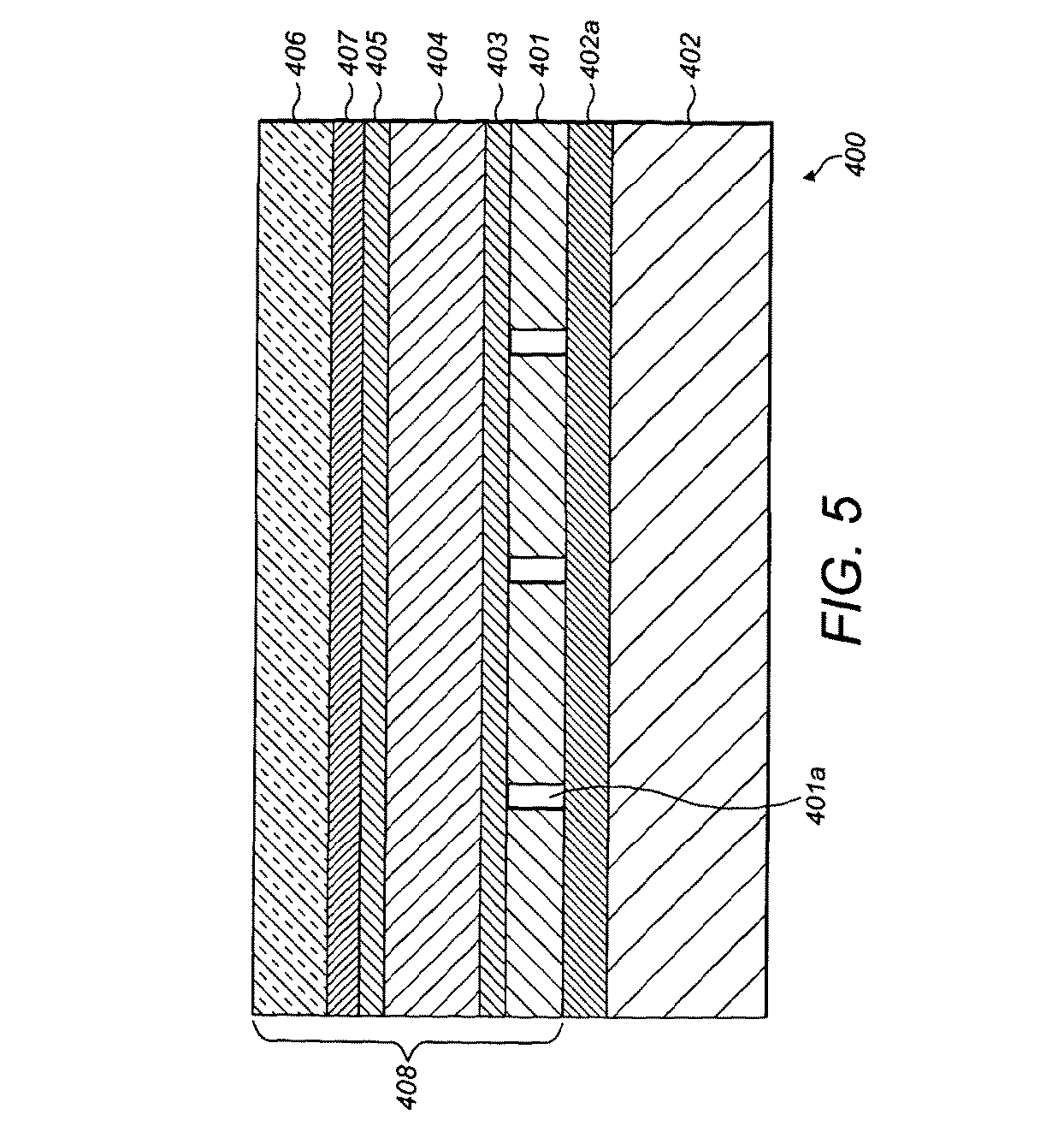
LCOSデバイスの構造が図5に示されている。 The structure of the LCOS device is shown in FIG.
LCOSデバイスは、単結晶シリコン基板(402)を使用して形成される。LCOSデバイスは、あるギャップ(401a)だけ間隔をおいて、基板の上面に配置された四角い平面状のアルミニウム電極(401)の2次元アレイを有する。各電極(401)は、基板(402)に埋め込まれた回路(402a)によってアドレス指定することができる。各電極は、個々の平面状の反射鏡を形成している。電極のアレイ上に配向膜(403)が配置され、配向膜(403)上に液晶層(404)が配置される。第2の配向膜(405)が液晶層(404)上に配置され、第2の配向膜(405)上にガラスなどの平面状の透明層(406)が配置される。透明層(406)と第2の配向膜(405)との間には、ITOなどの単一の透明電極(407)が配置される。 LCOS devices are formed using a single crystal silicon substrate (402). The LCOS device has a two-dimensional array of square planar aluminum electrodes (401) located on the top surface of the substrate, spaced by a gap (401a). Each electrode (401) can be addressed by a circuit (402a) embedded in the substrate (402). Each electrode forms an individual planar reflecting mirror. An alignment film (403) is disposed on the array of electrodes, and a liquid crystal layer (404) is disposed on the alignment film (403). A second alignment film (405) is arranged on the liquid crystal layer (404), and a flat transparent layer (406) such as glass is arranged on the second alignment film (405). A single transparent electrode (407) such as ITO is disposed between the transparent layer (406) and the second alignment film (405).
四角い電極(401)はそれぞれ、透明電極(407)および介在する液晶材料の重なり合う領域と相まって、画素と呼ばれることの多い制御可能な位相変調素子(408)を定義する。実効画素面積、すなわち充填率は、画素間の空間(401a)を考慮に入れた、光学活性を有する総画素のパーセンテージである。透明電極(407)に対して各電極(401)に印加される電圧を制御することにより、個々の位相変調素子の液晶材料の特性を変化させ、それによって、素子に入射する光に可変遅延が与えられ得る。その効果は、波面に位相のみの変調が提供されるものであり、すなわち、振幅の影響は生じない。 Each square electrode (401), in combination with a transparent electrode (407) and an overlapping region of intervening liquid crystal material, defines a controllable phase modulation element (408) often referred to as a pixel. The effective pixel area, or fill factor, is the percentage of total pixels with optical activity that takes into account the space between pixels (401a). By controlling the voltage applied to each electrode (401) with respect to the transparent electrode (407), the characteristics of the liquid crystal material of the individual phase modulation element are changed, which causes a variable delay in the light incident on the element. Can be given. The effect is that the wavefront is provided with phase-only modulation, ie no amplitude effect.
反射LCOS空間光変調器を使用することの主な利点は、液晶層が、それが透過型デバイスであった場合になるはずの半分の厚さになることである。これは液晶のスイッチング速度を大幅に改善する(動くビデオ画像の投影のためのキーポイント)。またLCOSデバイスは、独自に、位相のみの素子の大きなアレイを小さい開口において表示することができる。小型素子(典型的にはおおよそ10ミクロン(ミリメートル))は、結果として、光学系があまり長い光路を必要としないような実用的な回折角(数度)をもたらす。 The main advantage of using a reflective LCOS spatial light modulator is that the liquid crystal layer is half as thick as it would have been if it were a transmissive device. This greatly improves the switching speed of the liquid crystal (a key point for the projection of moving video images). The LCOS device is also uniquely capable of displaying large arrays of phase-only elements in small apertures. Small elements (typically around 10 microns (millimeters)) result in practical diffraction angles (several degrees) such that the optics do not require long optical paths.
LCOS SLMの小さい開口(数平方センチメートル)を照明する方が、より大きい液晶デバイスの開口を照明する場合よりも容易である。またLCOS SLMは大きな口径比を有し、画素間にほとんどデッドスペースが生じない(LCOS SLMを駆動するための回路が反射鏡の下に埋め込まれているため)。これは、再生場における光学雑音を低減する際に重要な問題である。 Illuminating the small aperture (several square centimeters) of the LCOS SLM is easier than illuminating the aperture of larger liquid crystal devices. Further, the LCOS SLM has a large aperture ratio, and almost no dead space occurs between pixels (because the circuit for driving the LCOS SLM is embedded under the reflecting mirror). This is an important issue in reducing optical noise in the reproduction field.
上記デバイスは、典型的には、10℃から約50℃までの温度範囲内で動作し、最適なデバイス動作温度は約40℃から50℃までである。 The devices typically operate within a temperature range of 10°C to about 50°C with optimal device operating temperatures of about 40°C to 50°C.
LCOSデバイスは、その制御電子回路がシリコンバックプレインに埋め込まれているため、画素の充填率がより高く、デバイスを離れる非分散光(unscattered light)がより少なくなる。 The LCOS device has a higher pixel fill factor and less unscattered light leaving the device because its control electronics are embedded in the silicon backplane.
シリコンバックプレインの使用には、画素が光学的に平坦であるという利点があり、これは位相変調デバイスにとって重要である。 The use of silicon backplanes has the advantage that the pixels are optically flat, which is important for phase modulation devices.
カラー2次元ホログラフィック再構成を生成することができ、これを成し遂げる方法は主に2つである。これらの方法の1つは、「FSC(frame−sequential colour:フレーム・シーケンス・カラー)」と呼ばれる。FSCシステムでは、3つのレーザ(赤、緑および青)が使用され、各レーザは、ビデオの各フレームを生成するためにSLMにおいて連続して発射される。各色は、人間の目視者に3つのレーザの組み合わせからの多色画像が見えるように十分に速いレートで繰り返される(赤、緑、青、赤、緑、青など)。したがって各ホログラムは色別のものである。例えば、1秒当たり25フレームのビデオでは、第1のフレームが赤色レーザを1/75秒にわたって発射することによって生成され、次いで、緑色レーザが1/75秒にわたって発射され、最後に青色レーザが1/75秒にわたって発射されるはずである。次いで、次のフレームが赤色レーザから以下同様に生成されるはずである。 Color two-dimensional holographic reconstructions can be generated, and there are two main ways to accomplish this. One of these methods is called "FSC (frame-sequential color)". In the FSC system, three lasers (red, green and blue) are used and each laser is fired sequentially on the SLM to produce each frame of video. Each color is repeated at a sufficiently fast rate (red, green, blue, red, green, blue, etc.) so that a human viewer sees a multicolor image from the combination of the three lasers. Therefore, each hologram is color-specific. For example, in a video of 25 frames per second, the first frame is produced by firing a red laser for 1/75 seconds, then a green laser for 1/75 seconds, and finally a blue laser for 1 /Should be fired for 75 seconds. The next frame would then be generated from the red laser and so on.
別の方法は、「SSC(spatially separated colours:空間的に分離された色)」と呼ばれ、3つのレーザすべてが同時に発射されるが異なる光路を辿り、例えば、それぞれが異なるSLMを使用し、次いでカラー画像を形成するように組み合わされることを伴う。 Another method is called "SSC (spatially separated colors)", where all three lasers are fired at the same time but follow different optical paths, eg each using a different SLM, It then involves being combined to form a color image.
FSC(frame−sequential colour)法の利点は、全SLMが色ごとに使用されることである。これは、SLM上のすべての画素がカラー画像のそれぞれに使用されるために、生成される三色画像の品質が損なわれないことを意味する。しかし、FSC法の不都合点は、各レーザが3分の1の時間にわたってしか使用されないために、生成される全体画像が、SSC法によって生成される対応する画像の約3分の1の明るさになることである。この欠点には、おそらくは、レーザを過励振することにより、またはより強力なレーザを使用することにより対処できるはずであるが、これにはより多くの電力の使用が必要とされ、より高いコストを伴い、システムのコンパクト性を低下させることになるはずである。 The advantage of the FSC (frame-sequential color) method is that all SLMs are used for each color. This means that the quality of the three-color image produced is not compromised because all pixels on the SLM are used for each of the color images. However, the disadvantage of the FSC method is that each laser is used for only one-third of the time, so that the overall image produced is about one-third as bright as the corresponding image produced by the SSC method. Is to become. This drawback could probably be addressed by over-exciting the laser, or by using a more powerful laser, but this requires more power to be used and is more costly. As a result, the compactness of the system should be reduced.
SSC(spatially separated colours)法の利点は、3つすべてのレーザが同時に発射されるために画像がより明るいことである。しかし、スペースの限界のためにただ1つのSLMだけを使用する必要がある場合には、SLMの表面積を3つの等しい部分に分け、事実上3つの別々のSLMとして働かせることができる。この方法の欠点は、各単色画像に使用できるSLM表面積が低減されるために、各単色画像の品質が低下することである。したがって、多色画像の品質もそれに対応して低下する。使用できるSLM表面積の低減は、SLM上のより少数の画素が使用され、よって、画像の品質が低下し得ることを意味する。画素の品質は、その解像度が低減されるために低下する。 An advantage of the SSC (spatially separated colors) method is that the image is brighter because all three lasers are fired at the same time. However, if only one SLM needs to be used due to space limitations, the surface area of the SLM can be divided into three equal parts, effectively acting as three separate SLMs. The drawback of this method is that the quality of each monochromatic image is degraded due to the reduction of the SLM surface area available for each monochromatic image. Therefore, the quality of the multicolor image is correspondingly reduced. The reduction in available SLM surface area means that fewer pixels on the SLM are used and thus the quality of the image may be reduced. The quality of a pixel is degraded due to its reduced resolution.
各実施形態は「タイリング」の技法を実施し、タイリングではSLMの表面積がいくつかのタイルへさらに分割され、各タイルは、元のタイルと同様の、または同一の位相分布において設定される。したがって各タイルは、SLMの全割振り面積が1つの大きな位相パターンとして使用された場合よりも小さい表面積のものである。タイル内の周波数成分の数が小さいほど、再構成される画素は、画像が生成されるときにより遠くに分離される。画像はゼロ次の回折次数内で作成され、1次および後続の次数は、画像と重なり合わないように十分遠くに変位され、空間フィルタによって遮断され得ることが好ましい。 Each embodiment implements a "tiling" technique in which the surface area of the SLM is subdivided into several tiles, each tile set in a similar or identical phase distribution as the original tile. .. Thus, each tile is of smaller surface area than if the total allocated area of the SLM were used as one large phase pattern. The smaller the number of frequency components in the tile, the farther the reconstructed pixels will be separated when the image is generated. The image is created within the zeroth diffraction order, preferably the first and subsequent orders are displaced far enough so that they do not overlap the image and can be blocked by spatial filters.
前述のように、(タイリングありであれなしであれ)この方法によって生成される画像は、画像画素を形成する点を含む。使用されるタイルの数が大きいほど、これらの点は小さくなる。無限正弦波のフーリエ変換を例に取ると、単一周波数が生成される。これは最適な出力である。実際には、ただ1つのタイルが使用される場合、これは正弦波の単一位相の入力に対応し、正弦波の終端ノード(end node)から正と負の方向に無限遠まで延在するゼロ値を有する。単一周波数がそのフーリエ変換から生成されるのではなく、基本周波数成分(principle frequency component)は、そのどちらの側にも一連の隣接する周波数成分を伴って生成される。タイリングの使用は、これらの隣接する周波数成分の振幅を低減し、その直接の結果として、隣接する画像画素間で生じる干渉が(強め合う干渉であれ、弱め合う干渉であれ)より少なくなり、それによって画像品質が改善される。 As mentioned above, the image produced by this method (with or without tiling) comprises points forming image pixels. The larger the number of tiles used, the smaller these points. Taking the Fourier transform of an infinite sine wave as an example, a single frequency is generated. This is the optimum output. In practice, if only one tile is used, this corresponds to a single phase input of a sine wave, extending from the end node of the sine wave to infinity in the positive and negative directions. It has a zero value. Rather than a single frequency being generated from its Fourier transform, a prime frequency component is generated with a series of adjacent frequency components on either side of it. The use of tiling reduces the amplitude of these adjacent frequency components, the direct result of which is less interference (whether constructive or destructive) between adjacent image pixels, This improves the image quality.
好ましくは、各タイルは完全なタイルであるが、タイルの部分を使用することも可能である。 Preferably, each tile is a complete tile, but it is also possible to use parts of the tile.
物体の画像が画像面に対して異なる深さのところに形成され得るように、空間光変調器に適用される画像化データを変更するのと同時に空間光変調器上のレンズ法データを変更するステップを含む、画像を表示する方法が提供される。 Modifying the lensing data on the spatial light modulator at the same time as modifying the imaging data applied to the spatial light modulator so that the image of the object can be formed at different depths relative to the image plane. A method of displaying an image is provided that includes steps.
この画像面は、仮想画像化システムにおいて使用され得る。 This image plane can be used in a virtual imaging system.
データを変更するステップは、異なる深さのところに形成される複数の画像が人間の目に同時に存在するように見えるように実行され得る。 The step of modifying the data may be performed such that multiple images formed at different depths appear to be present simultaneously to the human eye.
SLMに画像を形成するためのデータを適用するステップと、SLMを照明するステップと、結果として得られる光を、仮想画像を形成するための光学系に当てるステップとを含む、表示する方法が提供され、SLMに適用されるデータは第1のデータと第2のデータとを含み、第1のデータは画像のコンテンツに関連し、第2のデータは、SLMによって少なくとも1つのレンズ法機能を提供するように決定され、この方法は、第2のデータを、異なる深さのところに形成される複数の画像が人間の目に同時に存在するように見えるように変更するステップをさらに含む。 Provided is a method of displaying, comprising applying data to form an image on an SLM, illuminating the SLM, and applying the resulting light to an optical system for forming a virtual image. The data applied to the SLM includes first data and second data, the first data being related to the content of the image, the second data providing at least one lensing function by the SLM. The method further comprises modifying the second data such that the plurality of images formed at different depths appear to be present simultaneously to the human eye.
この方法は、複数の画像が相互に異なるように第1のデータを変更するステップを含んでいてもよい。 The method may include modifying the first data such that the plurality of images differ from each other.
SLMと、SLMを操作するための回路と、SLMを照明するための照明装置と、SLM上のデータから再構成される仮想画像を形成するように適合された光学系とを備えるディスプレイが提供され、回路は、SLMに画像を形成するためのデータを適用するように適合されており、適用されるデータは第1のデータと第2のデータとを含み、第1のデータは画像のコンテンツに関連し、第2のデータはSLMによって少なくとも1つのレンズ法機能を提供するように決定され、回路は、第2のデータを、異なる深さのところに形成される複数の画像が人間の目に同時に存在するように見えるように変更するように適合されている。 Provided is a display comprising an SLM, circuitry for operating the SLM, a lighting device for illuminating the SLM, and optics adapted to form a virtual image reconstructed from the data on the SLM. , The circuit is adapted to apply data for forming an image to the SLM, the applied data comprising first data and second data, the first data being the content of the image. Relatedly, the second data is determined by the SLM to provide at least one lenticular function and the circuit provides the second data with multiple images formed at different depths to the human eye. It is adapted to change to appear to exist at the same time.
光学系はフーリエレンズを備えていてもよい。 The optical system may include a Fourier lens.
ディスプレイは、ヘッドアップディスプレイを形成していてもよい。 The display may form a head-up display.
本発明は、前述の実施形態だけに限定されず、添付の特許請求の範囲の全範囲に及ぶものである。 The invention is not limited to the embodiments described above, but extends to the full scope of the appended claims.
Claims (11)
前記光学系が、
前記処理システムから受け取った第1のホログラフィックデータに対応した空間光変調を行う空間光変調器と、
前記空間光変調器を照明し、前記第1のホログラフィックデータに従って空間変調光を生成するように構成された光源と、
前記空間変調光をフーリエ変換し、第1の再生場に前記第1のホログラフィックデータに対応する第1の2次元ホログラフィック再構成画像を空間領域において生成するように構成されたフーリエ変換レンズと、
現実の前記第1の2次元ホログラフィック再構成画像の第1の仮想画像を形成するように構成された目視システムとを備え、
前記処理システムが、
前記第1のホログラフィックデータを生成するために、第1の2次元画像を表す第1のフーリエ変換データを、前記第1の2次元ホログラフィック再構成画像の前記第1の仮想画像が形成される位置を表す第1のデータと組み合わせ、
前記第1のホログラフィックデータを前記空間光変調器へ提供するように構成され、
前記目視システムが、
光コンバイナと、
前記第1の再生場と前記光コンバイナの間に配置された目視レンズとを備え、
前記処理システムが、前記第1のデータのレンズ特性を変化させることにより、光軸に沿って前記第1の再生場の位置を変化させるように構成され、
前記目視レンズ及び前記第1のデータのレンズ特性が、現実の前記第1の2次元ホログラフィック再構成画像と前記目視レンズの間の距離が前記目視レンズの焦点距離よりも短くなるように構成されており、
これにより、前記目視レンズが現実の前記第1の2次元ホログラフィック再構成画像の前記第1の仮想画像を形成し、前記第1の仮想画像が前記光コンバイナを介して知覚される
表示システム。 A display system comprising an optical system and a processing system,
The optical system is
A spatial light modulator that performs spatial light modulation corresponding to the first holographic data received from the processing system;
A light source configured to illuminate the spatial light modulator and generate spatially modulated light according to the first holographic data;
A Fourier transform lens configured to Fourier transform the spatially modulated light to generate a first two-dimensional holographic reconstructed image corresponding to the first holographic data in a spatial domain in a first reproduction field; ,
A viewing system configured to form a first virtual image of the first two-dimensional holographic reconstructed image of reality,
The processing system is
First Fourier transform data representing a first two-dimensional image is formed into the first virtual image of the first two-dimensional holographic reconstructed image to generate the first holographic data. Combined with the first data representing the position
Configured to provide the first holographic data to the spatial light modulator,
The visual system is
An optical combiner,
A visual lens disposed between the first reproduction field and the optical combiner,
The processing system is configured to change a position of the first reproduction field along an optical axis by changing a lens characteristic of the first data,
The lens characteristics of the visual lens and the first data are configured such that the distance between the actual first two-dimensional holographic reconstructed image and the visual lens is shorter than the focal length of the visual lens. And
Thereby, the visual lens forms the first virtual image of the first real two-dimensional holographic reconstructed image, and the first virtual image is perceived via the optical combiner.
第2のホログラフィックデータを生成するために、第2の2次元画像を表す第2のフーリエ変換データを、現実の第2の2次元ホログラフィック再構成画像の第2の仮想画像が形成される位置を表す第2のデータと組み合わせ、
前記第2のホログラフィックデータを前記空間光変調器へ提供して、第2の再生場に現実の前記第2の2次元ホログラフィック再構成画像を空間領域において生成するように構成されており、
前記第1の再生場と前記第2の再生場が相互に対して光軸に沿って空間的に変位されている、
請求項1に記載の表示システム。 The processing system further comprises
A second virtual image of the actual second two-dimensional holographic reconstructed image is formed from the second Fourier transform data representing the second two-dimensional image to generate the second holographic data. Combined with the second data that represents the position,
Providing the second holographic data Previous Symbol spatial light modulator, and the second two-dimensional holographic reconstruction image of reality second reproduction field is configured to produce in the spatial domain ,
The first reproduction field and the second reproduction field are spatially displaced relative to each other along an optical axis,
The display system according to claim 1.
請求項1に記載の表示システム。 The spatial light modulator comprises an array of pixelated diffractive elements,
The display system according to claim 1.
請求項2に記載の表示システム。 The first virtual image and the second virtual image appear to a viewer at the same time,
The display system according to claim 2.
請求項1から請求項4のいずれかに記載の表示システム。 The spatial light modulator is a reflective liquid crystal device (LCOS) spatial light modulator,
The display system according to any one of claims 1 to 4.
請求項1から請求項5のいずれかに記載の表示システム。 The depth of the first playing field is controlled by the user,
The display system according to any one of claims 1 to 5.
請求項1から請求項6のいずれかに記載の表示システム。 Configure the HUD,
The display system according to any one of claims 1 to 6.
請求項1から請求項7のいずれかに記載の表示システム。 Further comprising a spatial filter provided with a physical aperture for passing a particular diffraction order of said first two-dimensional holographic reconstruction of reality,
The display system according to any one of claims 1 to 7.
請求項2に記載の表示システム。 The first virtual image and the second virtual image are consecutive frames of two-dimensional video,
The display system according to claim 2.
第1のホログラフィックデータを生成するために、第1の2次元画像を表す第1のフーリエ変換データを、第1の2次元ホログラフィック再構成画像の第1の仮想画像が形成される位置を表す第1のデータと組み合わせるステップと、
前記第1のホログラフィックデータを空間光変調器へ入力するステップと、
前記空間光変調器を照明し、前記第1のホログラフィックデータに従って空間変調光を生成するステップと、
前記空間変調光を、フーリへ変換レンズを備える光学系に当てるステップと、
前記フーリエ変換レンズを用いて前記空間変調光をフーリエ変換し、第1の再生場に前記第1のホログラフィックデータに対応する現実の前記第1の2次元ホログラフィック再構成画像を空間領域において生成するステップと、
前記第1のデータのレンズ特性を変換して、光軸に沿って前記第1の再生場の位置を変化させるステップと、
目視システムを用いて現実の前記第1の2次元ホログラフィック再構成画像の第1の仮想画像を形成するステップであって、前記目視システムが、光コンバイナと、前記第1の再生場と前記光コンバイナの間に配置された目視レンズとを備えるステップと、を含み、
前記目視レンズ及び前記第1のデータのレンズ特性が、現実の前記第1の2次元ホログラフィック再構成画像と前記目視レンズの間の距離が前記目視レンズの焦点距離よりも短くなるように構成されており、
これにより、前記目視レンズが現実の前記第1の2次元ホログラフィック再構成画像の前記第1の仮想画像を形成し、前記第1の仮想画像が前記光コンバイナを介して知覚される
方法。 A method of displaying an image,
In order to generate the first holographic data, the first Fourier transform data representing the first two-dimensional image is transferred to a position where the first virtual image of the first two-dimensional holographic reconstructed image is formed. Combining with the first data to represent,
Inputting the first holographic data to a spatial light modulator;
Illuminating the spatial light modulator to generate spatially modulated light according to the first holographic data;
Applying the spatially modulated light to an optical system including a conversion lens to a Fourier,
Fourier transform the spatially modulated light using the Fourier transform lens to generate an actual first two-dimensional holographic reconstructed image corresponding to the first holographic data in a spatial domain in a first reproduction field. Steps to
Converting the lens characteristics of the first data to change the position of the first reproduction field along the optical axis;
Forming a first virtual image of the first two-dimensional holographic reconstructed image of reality using a viewing system, the viewing system comprising an optical combiner, the first reproduction field and the light. And a visual lens disposed between the combiners.
The lens characteristics of the visual lens and the first data are configured such that the distance between the actual first two-dimensional holographic reconstructed image and the visual lens is shorter than the focal length of the visual lens. And
Whereby the viewing lens forms the first virtual image of the first real two-dimensional holographic reconstructed image, the first virtual image being perceived via the optical combiner.
請求項10に記載の方法。 Further comprising spatially filtering the resulting light from the spatial light modulator to selectively block at least one diffraction order of the first two-dimensional holographic reconstructed image of reality.
The method according to claim 10.
Applications Claiming Priority (2)
| Application Number | Priority Date | Filing Date | Title |
|---|---|---|---|
| GB1011829.7 | 2010-07-14 | ||
| GBGB1011829.7A GB201011829D0 (en) | 2010-07-14 | 2010-07-14 | Display system |
Related Parent Applications (1)
| Application Number | Title | Priority Date | Filing Date |
|---|---|---|---|
| JP2013519160A Division JP6154321B2 (en) | 2010-07-14 | 2011-07-14 | 2D / 3D holographic display system |
Publications (2)
| Publication Number | Publication Date |
|---|---|
| JP2017142506A JP2017142506A (en) | 2017-08-17 |
| JP6711769B2 true JP6711769B2 (en) | 2020-06-17 |
Family
ID=42734922
Family Applications (2)
| Application Number | Title | Priority Date | Filing Date |
|---|---|---|---|
| JP2013519160A Active JP6154321B2 (en) | 2010-07-14 | 2011-07-14 | 2D / 3D holographic display system |
| JP2017039851A Active JP6711769B2 (en) | 2010-07-14 | 2017-03-02 | 2D/3D holographic display system |
Family Applications Before (1)
| Application Number | Title | Priority Date | Filing Date |
|---|---|---|---|
| JP2013519160A Active JP6154321B2 (en) | 2010-07-14 | 2011-07-14 | 2D / 3D holographic display system |
Country Status (5)
| Country | Link |
|---|---|
| US (3) | US9715215B2 (en) |
| EP (1) | EP2593838B1 (en) |
| JP (2) | JP6154321B2 (en) |
| GB (2) | GB201011829D0 (en) |
| WO (1) | WO2012007762A1 (en) |
Families Citing this family (133)
| Publication number | Priority date | Publication date | Assignee | Title |
|---|---|---|---|---|
| GB201011829D0 (en) | 2010-07-14 | 2010-09-01 | Two Trees Photonics Ltd | Display system |
| GB2498170B (en) | 2011-10-26 | 2014-01-08 | Two Trees Photonics Ltd | Frame inheritance |
| GB2499579B (en) | 2012-02-07 | 2014-11-26 | Two Trees Photonics Ltd | Lighting device |
| GB2501112B (en) | 2012-04-12 | 2014-04-16 | Two Trees Photonics Ltd | Phase retrieval |
| WO2014073201A1 (en) * | 2012-11-08 | 2014-05-15 | パナソニック株式会社 | Display device using computer generated hologram |
| GB2509180B (en) | 2012-12-21 | 2015-04-08 | Two Trees Photonics Ltd | Projector |
| GB2515460B (en) | 2013-04-12 | 2016-01-06 | Two Trees Photonics Ltd | Near-eye device |
| GB201314029D0 (en) * | 2013-08-06 | 2013-09-18 | Bae Systems Plc | Display system |
| WO2015019064A1 (en) * | 2013-08-06 | 2015-02-12 | Bae Systems Plc | Display system |
| EP2835679A1 (en) * | 2013-08-06 | 2015-02-11 | BAE Systems PLC | Display system |
| JP6632979B2 (en) * | 2013-09-04 | 2020-01-22 | エシロール・アンテルナシオナル | Methods and systems for augmented reality |
| JP6068303B2 (en) * | 2013-09-17 | 2017-01-25 | アルプス電気株式会社 | Image projection device |
| EP4009626A1 (en) * | 2013-10-20 | 2022-06-08 | Mtt Innovation Incorporated | Light field projectors and methods |
| JP6087788B2 (en) * | 2013-10-31 | 2017-03-01 | アルプス電気株式会社 | In-vehicle projector |
| WO2015064497A1 (en) * | 2013-10-31 | 2015-05-07 | アルプス電気株式会社 | In-vehicle projection device |
| WO2015172236A1 (en) | 2014-05-15 | 2015-11-19 | Mtt Innovation Incorporated | Optimizing drive schemes for multiple projector systems |
| GB2526158B (en) * | 2014-05-16 | 2017-12-20 | Two Trees Photonics Ltd | Imaging device for moving a virtual image |
| GB2526159B (en) * | 2014-05-16 | 2017-12-20 | Two Trees Photonics Ltd | Diffuser for head-up display |
| TWI578119B (en) * | 2014-12-15 | 2017-04-11 | 國立交通大學 | Image display device |
| FR3033904B1 (en) * | 2015-03-17 | 2018-04-27 | Valeo Comfort And Driving Assistance | HEAD DISPLAY DEVICE, IN PARTICULAR FOR A MOTOR VEHICLE |
| JP2016176996A (en) * | 2015-03-18 | 2016-10-06 | アルプス電気株式会社 | Image projection device |
| JP2016177196A (en) * | 2015-03-20 | 2016-10-06 | アルプス電気株式会社 | Image display device |
| US10571862B1 (en) | 2015-05-21 | 2020-02-25 | Real View Imaging Ltd. | Producing a computer generated holographic image |
| US9810910B1 (en) | 2015-05-28 | 2017-11-07 | Verily Life Sciences Llc | Contact lens with phase map display |
| US9798147B1 (en) | 2015-05-28 | 2017-10-24 | Verily Life Sciences Llc | Near-eye display with phase map |
| US10203499B2 (en) * | 2015-08-24 | 2019-02-12 | Finisar Corporation | Image projection system |
| JP6793297B2 (en) * | 2015-10-05 | 2020-12-02 | パナソニックIpマネジメント株式会社 | Projection type image display device |
| JP6607489B2 (en) * | 2015-10-26 | 2019-11-20 | 国立研究開発法人情報通信研究機構 | Hologram data generation device and program thereof |
| CN108351951B (en) | 2015-10-26 | 2023-02-07 | 瑞尔D斯帕克有限责任公司 | Intelligent privacy system, equipment and method thereof |
| CN108027583B (en) | 2015-12-30 | 2020-10-09 | 杜尔利塔斯有限公司 | Dynamic holographic non-scanning printing device |
| WO2017115081A1 (en) | 2015-12-30 | 2017-07-06 | Daqri Holographics Ltd | Near eye dynamic holography |
| DE202016008701U1 (en) | 2015-12-30 | 2019-02-07 | Dualitas Ltd. | Dynamic holography-oriented gravure printing device |
| US10092177B1 (en) * | 2015-12-30 | 2018-10-09 | Verily Life Sciences Llc | Device, system and method for image display with a programmable phase map |
| WO2017145158A1 (en) | 2016-02-22 | 2017-08-31 | Real View Imaging Ltd. | Zero order blocking and diverging for holographic imaging |
| EP3420414B1 (en) | 2016-02-22 | 2025-01-01 | Real View Imaging Ltd. | Holographic display |
| US10795316B2 (en) | 2016-02-22 | 2020-10-06 | Real View Imaging Ltd. | Wide field of view hybrid holographic display |
| EP3420413A1 (en) | 2016-02-22 | 2019-01-02 | Real View Imaging Ltd. | A method and system for displaying holographic images within a real object |
| US11663937B2 (en) | 2016-02-22 | 2023-05-30 | Real View Imaging Ltd. | Pupil tracking in an image display system |
| GB2547926B (en) * | 2016-03-03 | 2020-04-29 | Dualitas Ltd | Display system |
| GB2547929B (en) | 2016-03-03 | 2018-02-21 | Daqri Holographics Ltd | Display system |
| US11079619B2 (en) | 2016-05-19 | 2021-08-03 | Reald Spark, Llc | Wide angle imaging directional backlights |
| WO2018109902A1 (en) | 2016-12-15 | 2018-06-21 | アルプス電気株式会社 | Image display device |
| KR101921798B1 (en) * | 2016-12-26 | 2018-11-26 | 경북대학교 산학협력단 | Apparatus for generating 3-dimensional picture |
| US10317674B2 (en) * | 2017-01-31 | 2019-06-11 | City University Of Hong Kong | Augmented reality systems and methods |
| EP3596537A1 (en) | 2017-03-17 | 2020-01-22 | Compound Photonics Limited | Imaging systems and methods |
| CN106896506B (en) | 2017-04-28 | 2019-07-26 | 京东方科技集团股份有限公司 | A kind of head-up display, head-up display method and vehicle |
| EP3622342A4 (en) | 2017-05-08 | 2021-02-17 | RealD Spark, LLC | OPTICAL STACKING FOR DIRECTIONAL DISPLAY |
| US10126575B1 (en) | 2017-05-08 | 2018-11-13 | Reald Spark, Llc | Optical stack for privacy display |
| CN110809732B (en) | 2017-05-08 | 2025-01-10 | 瑞尔D斯帕克有限责任公司 | Optical stack for imaging directional backlights |
| US10347030B2 (en) | 2017-05-15 | 2019-07-09 | Envisics Ltd | Adjusting depth of augmented reality content on a heads up display |
| WO2018211074A1 (en) * | 2017-05-19 | 2018-11-22 | Seereal Technologies S.A. | Display device comprising a light guide |
| JP2018197844A (en) * | 2017-05-23 | 2018-12-13 | ヘ−ヨン・チョイ | Apparatus for spatially separated images |
| CN109031676B (en) * | 2017-06-08 | 2020-05-26 | 京东方科技集团股份有限公司 | Projection device, head-up display equipment and vehicle-mounted vision auxiliary system |
| GB2563873B (en) * | 2017-06-28 | 2022-03-02 | Yang Fan | Holographic image display apparatus |
| EP3686651B1 (en) | 2017-08-02 | 2021-10-20 | Envisics Ltd. | Display device |
| GB2567408B (en) | 2017-08-02 | 2020-12-02 | Dualitas Ltd | Holographic projector |
| GB2568021B (en) | 2017-09-08 | 2021-12-01 | Dualitas Ltd | Holographic projector |
| TWI878209B (en) | 2017-09-15 | 2025-04-01 | 美商瑞爾D斯帕克有限責任公司 | Display device and a view angle control optical element for application to a display device |
| US10948648B2 (en) | 2017-09-29 | 2021-03-16 | Reald Spark, Llc | Backlights having stacked waveguide and optical components with different coefficients of friction |
| US11070791B2 (en) | 2017-11-06 | 2021-07-20 | Reald Spark, Llc | Privacy display apparatus |
| KR20200096811A (en) | 2017-12-07 | 2020-08-13 | 시리얼 테크놀로지즈 에스.에이. | Head up display |
| US11392014B2 (en) | 2017-12-15 | 2022-07-19 | Nec Corporation | Projection device, interface device, and projection method |
| KR102455583B1 (en) * | 2017-12-29 | 2022-10-17 | 엘지디스플레이 주식회사 | Stereoscopic Display apparatus |
| KR20250002804A (en) | 2018-01-16 | 2025-01-07 | 퍼시픽 라이트 앤드 홀로그램 인크. | Three-dimensional displays using electromagnetic field computations |
| EP3743766B1 (en) | 2018-01-25 | 2026-02-11 | RealD Spark, LLC | Touch screen for privacy display |
| CN115718382A (en) | 2018-01-25 | 2023-02-28 | 瑞尔D斯帕克有限责任公司 | Reflective optical stack for privacy display device |
| US10935714B2 (en) | 2018-03-22 | 2021-03-02 | Reald Spark, Llc | Optical waveguide for directional backlight |
| CN112470063A (en) * | 2018-04-02 | 2021-03-09 | 杜比实验室特许公司 | System and method for digital laser projection for increasing contrast using fourier filters |
| EP3567419A1 (en) * | 2018-05-11 | 2019-11-13 | Essilor International (Compagnie Generale D'optique) | A system for generating a virtual image for a wearer |
| JP7026325B2 (en) * | 2018-06-21 | 2022-02-28 | パナソニックIpマネジメント株式会社 | Video display system, video display method, program, and mobile |
| US10955715B2 (en) | 2018-06-29 | 2021-03-23 | Reald Spark, Llc | Optical stack for privacy display |
| US11073735B2 (en) | 2018-07-18 | 2021-07-27 | Reald Spark, Llc | Optical stack for switchable directional display |
| GB2569208B (en) | 2018-07-19 | 2019-12-04 | Envisics Ltd | A head-up display |
| GB2580012A (en) | 2018-09-28 | 2020-07-15 | Envisics Ltd | Head-up display |
| WO2020072643A1 (en) | 2018-10-03 | 2020-04-09 | Reald Spark, Llc | Privacy display control apparatus |
| CN113167953B (en) | 2018-11-07 | 2023-10-24 | 瑞尔D斯帕克有限责任公司 | Directional display device |
| GB2578785C (en) | 2018-11-09 | 2023-08-09 | Dualitas Ltd | Pixel mapping onto a display device for holographic projection |
| GB2580298B (en) | 2018-11-12 | 2021-08-11 | Dualitas Ltd | A spatial light modulator for holographic projection |
| GB2579234B (en) | 2018-11-27 | 2023-07-19 | Dualitas Ltd | Hologram calculation |
| US11287677B2 (en) | 2019-01-07 | 2022-03-29 | Reald Spark, Llc | Optical stack for privacy display |
| GB2580696B (en) | 2019-01-25 | 2022-04-27 | Dualitas Ltd | A method for a holographic projector |
| JP7486822B2 (en) * | 2019-02-12 | 2024-05-20 | シーワイ・ビジョン・インコーポレイテッド | Holographic head-up display device |
| US11029566B2 (en) | 2019-02-12 | 2021-06-08 | Reald Spark, Llc | Diffuser for privacy display |
| GB2580441B (en) | 2019-03-14 | 2022-03-16 | Dualitas Ltd | Laser modulation |
| GB2582370B (en) | 2019-03-22 | 2022-11-02 | Dualitas Ltd | Holographic projector |
| GB2582965B (en) | 2019-04-11 | 2021-09-15 | Dualitas Ltd | A diffuser assembly |
| GB2583483B (en) * | 2019-04-29 | 2021-05-19 | Envisics Ltd | Image capture and display system |
| TWI912252B (en) | 2019-07-02 | 2026-01-21 | 美商瑞爾D斯帕克有限責任公司 | Directional display apparatus |
| EP4007930B1 (en) | 2019-08-02 | 2025-10-08 | RealD Spark, LLC | Optical stack for privacy display |
| GB2586512B (en) | 2019-08-23 | 2021-12-08 | Dualitas Ltd | Holographic projection |
| GB2586511B (en) | 2019-08-23 | 2021-12-01 | Dualitas Ltd | Holographic projector |
| KR102830276B1 (en) * | 2019-09-09 | 2025-07-04 | 삼성전자주식회사 | Multi-image display apparatus using holographic projection |
| GB2578523B (en) | 2019-09-25 | 2021-08-11 | Dualitas Ltd | Holographic projection |
| GB2587400B (en) * | 2019-09-27 | 2022-02-16 | Dualitas Ltd | Hologram display using a liquid crystal display device |
| US11114063B2 (en) | 2019-10-02 | 2021-09-07 | Reald Spark, Llc | Privacy display apparatus |
| CN114846393B (en) | 2019-11-13 | 2024-12-03 | 瑞尔D斯帕克有限责任公司 | Off-axis display device |
| WO2021118936A1 (en) | 2019-12-10 | 2021-06-17 | Reald Spark, Llc | Control of reflections of a display device |
| EP4078254B1 (en) | 2019-12-18 | 2024-09-25 | RealD Spark, LLC | Control of ambient light for a privacy display |
| GB2593750B (en) * | 2020-04-01 | 2024-04-03 | Envisics Ltd | A multi-plane display device |
| US11353752B2 (en) | 2020-04-30 | 2022-06-07 | Reald Spark, Llc | Directional display apparatus |
| WO2021222598A1 (en) | 2020-04-30 | 2021-11-04 | Reald Spark, Llc | Directional display apparatus |
| WO2021222615A1 (en) | 2020-04-30 | 2021-11-04 | Reald Spark, Llc | Directional display apparatus |
| CN113671696B (en) * | 2020-05-15 | 2022-10-11 | 华为技术有限公司 | Display device and display system |
| CN115702378A (en) * | 2020-06-22 | 2023-02-14 | 索尼集团公司 | Image display device and image display method |
| TWI898003B (en) | 2020-07-29 | 2025-09-21 | 美商瑞爾D斯帕克有限責任公司 | Pupillated illumination apparatus |
| EP4189285A4 (en) | 2020-07-29 | 2024-07-24 | RealD Spark, LLC | REAR LIGHTING FOR A SWITCHABLE DIRECTION INDICATOR |
| US11762333B2 (en) | 2020-09-17 | 2023-09-19 | Pacific Light & Hologram, Inc. | Reconstructing objects with display zero order light suppression |
| GB2604890B (en) * | 2021-03-17 | 2024-01-31 | Envisics Ltd | Image projection |
| CN113703166A (en) * | 2021-07-30 | 2021-11-26 | 的卢技术有限公司 | AR-HUD method and system through diffraction holographic imaging |
| US11892717B2 (en) | 2021-09-30 | 2024-02-06 | Reald Spark, Llc | Marks for privacy display |
| US11977286B2 (en) | 2022-02-09 | 2024-05-07 | Reald Spark, Llc | Observer-tracked privacy display |
| TW202332973A (en) | 2022-02-09 | 2023-08-16 | 美商瑞爾D斯帕克有限責任公司 | Display device with uniform off-axis luminance reduction |
| US11892718B2 (en) | 2022-04-07 | 2024-02-06 | Reald Spark, Llc | Directional display apparatus |
| WO2024004739A1 (en) * | 2022-06-28 | 2024-01-04 | ソニーグループ株式会社 | Information processing device, information processing method, and computer-readable non-transitory storage medium |
| WO2024143626A1 (en) * | 2022-12-29 | 2024-07-04 | (주)에픽옵틱스 | Optical device for generating holographic image |
| GB2627754B (en) * | 2023-02-28 | 2025-05-07 | Envisics Ltd | Optical system |
| US12523899B2 (en) | 2023-04-25 | 2026-01-13 | Reald Spark, Llc | Switchable privacy display |
| US11900842B1 (en) | 2023-05-12 | 2024-02-13 | Pacific Light & Hologram, Inc. | Irregular devices |
| US12243453B2 (en) | 2023-05-12 | 2025-03-04 | Pacific Light & Hologram, Inc. | Holographically displaying three-dimensional objects |
| US12288490B2 (en) | 2023-05-12 | 2025-04-29 | Pacific Light & Hologram, Inc. | Holographically displaying three-dimensional objects |
| US12300132B2 (en) | 2023-05-12 | 2025-05-13 | Pacific Light & Hologram, Inc. | Holographically displaying three-dimensional objects |
| US12315403B2 (en) | 2023-05-12 | 2025-05-27 | Pacific Light & Hologram, Inc. | Holographically displaying three-dimensional objects |
| US12266280B2 (en) | 2023-05-12 | 2025-04-01 | Pacific Light & Hologram, Inc. | Holographically displaying three-dimensional objects |
| US12374247B2 (en) | 2023-05-12 | 2025-07-29 | Pacific Light & Hologram, Inc. | Holographically displaying live scenes including three-dimensional objects |
| US12254797B2 (en) | 2023-05-12 | 2025-03-18 | Pacific Light & Hologram, Inc. | Holographically displaying live scenes including three-dimensional objects |
| US12293687B2 (en) | 2023-05-12 | 2025-05-06 | Pacific Light & Hologram, Inc. | Holographically displaying live scenes including three-dimensional objects |
| US12254798B2 (en) | 2023-05-12 | 2025-03-18 | Pacific Light & Hologram, Inc. | Holographically displaying three-dimensional objects |
| US12272279B2 (en) | 2023-05-12 | 2025-04-08 | Pacific Light & Hologram, Inc. | Holographically displaying three-dimensional objects |
| US12236816B2 (en) | 2023-05-12 | 2025-02-25 | Pacific Light & Hologram, Inc. | Holographically displaying live scenes including three-dimensional objects |
| US12230176B2 (en) | 2023-05-12 | 2025-02-18 | Pacific Light & Hologram, Inc. | Holographically displaying three-dimensional objects |
| US12266279B2 (en) | 2023-05-12 | 2025-04-01 | Pacific Light & Hologram, Inc. | Holographically displaying three-dimensional objects with optical devices having in-coupling and out-coupling diffractive structures |
| WO2025030030A2 (en) | 2023-08-03 | 2025-02-06 | Reald Spark, Llc | Privacy displays |
| US12281984B1 (en) | 2023-12-21 | 2025-04-22 | Pacific Light & Hologram, Inc. | Optical measurements |
Family Cites Families (46)
| Publication number | Priority date | Publication date | Assignee | Title |
|---|---|---|---|---|
| US4275454A (en) | 1978-12-01 | 1981-06-23 | Environmental Research Institute Of Michigan | Optical system phase error compensator |
| JP2868369B2 (en) * | 1992-07-08 | 1999-03-10 | シャープ株式会社 | Writing method of programmable optical element and hologram optical element and software development support device |
| JP3798511B2 (en) | 1997-06-11 | 2006-07-19 | 浜松ホトニクス株式会社 | Computer generated hologram display |
| US7127109B1 (en) * | 1999-09-27 | 2006-10-24 | University Of South Florida | Digital interference holographic microscope and methods |
| US6545790B2 (en) | 1999-11-08 | 2003-04-08 | Ralph W. Gerchberg | System and method for recovering phase information of a wave front |
| JP4499331B2 (en) | 1999-11-08 | 2010-07-07 | ウェイヴフロント アナリシス インコーポレイテッド | System and method for recovering wavefront phase information |
| US20010050787A1 (en) | 2000-05-22 | 2001-12-13 | Intelligent Pixels, Inc. | Electro-optical component having a reconfigurable phase state |
| GB0027103D0 (en) | 2000-11-07 | 2000-12-20 | Secr Defence | Improved 3D display |
| WO2003014837A1 (en) | 2001-07-26 | 2003-02-20 | Tesa Scribos Gmbh | Methods for calculating multilayer holograms, method for producing multilayer holograms and storage medium comprising a multilayer hologram |
| EP1467263A4 (en) | 2002-01-16 | 2009-12-16 | Japan Science & Tech Agency | HOLOGRAPHIC REPRODUCTION DEVICE FOR MOBILE IMAGES AND HOLOGRAPHIC REPRODUCTION DEVICE FOR COLOR MOBILE IMAGES |
| US6961159B2 (en) | 2002-08-02 | 2005-11-01 | Dai Nippon Printing Co, Ltd. | Holographic viewing device, and computer-generated hologram for the same |
| FR2857454B1 (en) | 2003-07-08 | 2006-08-11 | Aventis Pasteur | DOSAGE OF TECHIC ACIDS OF BACTERIA GRAM + |
| GB0329012D0 (en) | 2003-12-15 | 2004-01-14 | Univ Cambridge Tech | Hologram viewing device |
| JP4497912B2 (en) * | 2003-12-17 | 2010-07-07 | 富士フイルム株式会社 | Camera and zoom control method of camera |
| JP2005181854A (en) * | 2003-12-22 | 2005-07-07 | Sanyo Electric Co Ltd | Method for generating computer hologram |
| JP3760943B2 (en) | 2004-01-20 | 2006-03-29 | コニカミノルタフォトイメージング株式会社 | Imaging apparatus and moving image noise processing method |
| US7227611B2 (en) | 2004-08-23 | 2007-06-05 | The Boeing Company | Adaptive and interactive scene illumination |
| JP2006301020A (en) | 2005-04-15 | 2006-11-02 | Ricoh Co Ltd | Stereoscopic image display device, communication device equipped with the same, and mobile for transportation |
| GB0512179D0 (en) | 2005-06-15 | 2005-07-20 | Light Blue Optics Ltd | Holographic dispaly devices |
| JP4747296B2 (en) * | 2005-06-15 | 2011-08-17 | 国立大学法人九州工業大学 | How to visualize occluded space |
| GB0525336D0 (en) | 2005-12-13 | 2006-01-18 | Univ Cambridge Tech | Hologram viewing device |
| GB2436676B (en) | 2006-03-28 | 2008-02-20 | Light Blue Optics Ltd | Holographic display devices |
| GB2438026A (en) | 2006-05-11 | 2007-11-14 | Univ Cambridge Tech | Phase retrevial in hologram generation using amplitude and phase feedback |
| GB2438458A (en) | 2006-05-11 | 2007-11-28 | Univ Cambridge Tech | Blocking zero-order light in phase shift hologram generation |
| KR101029257B1 (en) | 2006-05-12 | 2011-04-18 | 무라타 기카이 가부시키가이샤 | Return system and return method |
| DE102006043402B4 (en) | 2006-09-15 | 2019-05-09 | Osram Gmbh | Lighting unit with an optical element |
| US20080106653A1 (en) | 2006-11-06 | 2008-05-08 | Harris Scott C | Spatial Light Modulator Techniques for Stage Lighting |
| DE102006055480A1 (en) * | 2006-11-24 | 2008-05-29 | Bayer Innovation Gmbh | Coding method, decoding method, codec and data carrier for holographic storage |
| DE102007007162A1 (en) | 2007-02-09 | 2008-08-14 | GM Global Technology Operations, Inc., Detroit | Holographic information display |
| GB2446852B (en) | 2007-02-12 | 2009-12-09 | Light Blue Optics Ltd | Data communication and processing system |
| US20080198372A1 (en) | 2007-02-21 | 2008-08-21 | Spatial Photonics, Inc. | Vehicle headlight with image display |
| GB2448132B (en) * | 2007-03-30 | 2012-10-10 | Light Blue Optics Ltd | Optical Systems |
| DE102007052643B4 (en) | 2007-11-05 | 2016-02-04 | Ivoclar Vivadent Ag | Light measuring device |
| GB2456170B (en) | 2008-01-07 | 2012-11-21 | Light Blue Optics Ltd | Holographic image display systems |
| GB2461294B (en) * | 2008-06-26 | 2011-04-06 | Light Blue Optics Ltd | Holographic image display systems |
| JP5047090B2 (en) * | 2008-07-31 | 2012-10-10 | キヤノン株式会社 | system |
| KR101497511B1 (en) * | 2008-09-19 | 2015-03-02 | 삼성전자주식회사 | APPARATUS FOR MULTIPLEXING 2 DIMENSIONAL and 3 DIMENSIONAL IMAGE AND VIDEO |
| JP2010079121A (en) * | 2008-09-29 | 2010-04-08 | Brother Ind Ltd | See-through display |
| GB0907965D0 (en) | 2009-05-08 | 2009-06-24 | King S College London | Imaging system |
| TWI640850B (en) | 2010-04-01 | 2018-11-11 | 喜瑞爾工業公司 | Method and device for encoding three-dimensional scenes which include transparent objects in a holographic system |
| GB201011829D0 (en) | 2010-07-14 | 2010-09-01 | Two Trees Photonics Ltd | Display system |
| GB2498170B (en) | 2011-10-26 | 2014-01-08 | Two Trees Photonics Ltd | Frame inheritance |
| GB2499579B (en) | 2012-02-07 | 2014-11-26 | Two Trees Photonics Ltd | Lighting device |
| GB2501112B (en) | 2012-04-12 | 2014-04-16 | Two Trees Photonics Ltd | Phase retrieval |
| GB2509180B (en) | 2012-12-21 | 2015-04-08 | Two Trees Photonics Ltd | Projector |
| GB2576738B (en) * | 2018-08-29 | 2020-08-19 | Envisics Ltd | Head-up display |
-
2010
- 2010-07-14 GB GBGB1011829.7A patent/GB201011829D0/en not_active Ceased
-
2011
- 2011-07-14 JP JP2013519160A patent/JP6154321B2/en active Active
- 2011-07-14 EP EP11735689.9A patent/EP2593838B1/en active Active
- 2011-07-14 GB GB1112128.2A patent/GB2482065B/en active Active
- 2011-07-14 WO PCT/GB2011/051328 patent/WO2012007762A1/en not_active Ceased
- 2011-07-14 US US13/810,001 patent/US9715215B2/en active Active
-
2017
- 2017-03-02 JP JP2017039851A patent/JP6711769B2/en active Active
- 2017-07-24 US US15/658,052 patent/US10928776B2/en active Active
-
2021
- 2021-02-16 US US17/176,355 patent/US11635621B2/en active Active
Also Published As
| Publication number | Publication date |
|---|---|
| GB201011829D0 (en) | 2010-09-01 |
| US9715215B2 (en) | 2017-07-25 |
| US20210341879A1 (en) | 2021-11-04 |
| GB2482065B (en) | 2014-01-08 |
| US11635621B2 (en) | 2023-04-25 |
| JP2013540278A (en) | 2013-10-31 |
| GB2482065A (en) | 2012-01-18 |
| WO2012007762A1 (en) | 2012-01-19 |
| US10928776B2 (en) | 2021-02-23 |
| US20170364028A1 (en) | 2017-12-21 |
| JP2017142506A (en) | 2017-08-17 |
| GB201112128D0 (en) | 2011-08-31 |
| US20130265622A1 (en) | 2013-10-10 |
| JP6154321B2 (en) | 2017-06-28 |
| EP2593838B1 (en) | 2018-07-04 |
| EP2593838A1 (en) | 2013-05-22 |
Similar Documents
| Publication | Publication Date | Title |
|---|---|---|
| JP6711769B2 (en) | 2D/3D holographic display system | |
| JP6704018B2 (en) | Near eye device | |
| US12013533B2 (en) | Holographic image projection with holographic correction | |
| CN101176043B (en) | Projection device and method for holographic reconstruction of scenes | |
| TWI659235B (en) | Holographic projection system and method of forming a holographic reconstruction in a holographic replay field having a rectangular shape | |
| GB2496108A (en) | Image colour frequency-based pixel number allocation | |
| GB2554575A (en) | Diffuser for head-up display | |
| HK1258061B (en) | Near-eye device |
Legal Events
| Date | Code | Title | Description |
|---|---|---|---|
| A621 | Written request for application examination |
Free format text: JAPANESE INTERMEDIATE CODE: A621 Effective date: 20170302 |
|
| A521 | Request for written amendment filed |
Free format text: JAPANESE INTERMEDIATE CODE: A523 Effective date: 20170315 |
|
| A977 | Report on retrieval |
Free format text: JAPANESE INTERMEDIATE CODE: A971007 Effective date: 20171116 |
|
| A131 | Notification of reasons for refusal |
Free format text: JAPANESE INTERMEDIATE CODE: A131 Effective date: 20171212 |
|
| A521 | Request for written amendment filed |
Free format text: JAPANESE INTERMEDIATE CODE: A523 Effective date: 20180213 |
|
| A131 | Notification of reasons for refusal |
Free format text: JAPANESE INTERMEDIATE CODE: A131 Effective date: 20180227 |
|
| A521 | Request for written amendment filed |
Free format text: JAPANESE INTERMEDIATE CODE: A523 Effective date: 20180507 |
|
| A02 | Decision of refusal |
Free format text: JAPANESE INTERMEDIATE CODE: A02 Effective date: 20180522 |
|
| A521 | Request for written amendment filed |
Free format text: JAPANESE INTERMEDIATE CODE: A523 Effective date: 20181106 |
|
| A521 | Request for written amendment filed |
Free format text: JAPANESE INTERMEDIATE CODE: A821 Effective date: 20181106 |
|
| A521 | Request for written amendment filed |
Free format text: JAPANESE INTERMEDIATE CODE: A523 Effective date: 20200313 |
|
| A61 | First payment of annual fees (during grant procedure) |
Free format text: JAPANESE INTERMEDIATE CODE: A61 Effective date: 20200528 |
|
| R150 | Certificate of patent or registration of utility model |
Ref document number: 6711769 Country of ref document: JP Free format text: JAPANESE INTERMEDIATE CODE: R150 |
|
| S111 | Request for change of ownership or part of ownership |
Free format text: JAPANESE INTERMEDIATE CODE: R313113 |
|
| S531 | Written request for registration of change of domicile |
Free format text: JAPANESE INTERMEDIATE CODE: R313531 |
|
| S533 | Written request for registration of change of name |
Free format text: JAPANESE INTERMEDIATE CODE: R313533 |
|
| R350 | Written notification of registration of transfer |
Free format text: JAPANESE INTERMEDIATE CODE: R350 |
|
| S531 | Written request for registration of change of domicile |
Free format text: JAPANESE INTERMEDIATE CODE: R313531 |
|
| R350 | Written notification of registration of transfer |
Free format text: JAPANESE INTERMEDIATE CODE: R350 |
|
| R250 | Receipt of annual fees |
Free format text: JAPANESE INTERMEDIATE CODE: R250 |
|
| R250 | Receipt of annual fees |
Free format text: JAPANESE INTERMEDIATE CODE: R250 |
|
| R250 | Receipt of annual fees |
Free format text: JAPANESE INTERMEDIATE CODE: R250 |