JP6694227B2 - Coil-shaped wire rod cleaning nozzle member and coil-shaped wire rod cleaning device including the same - Google Patents
Coil-shaped wire rod cleaning nozzle member and coil-shaped wire rod cleaning device including the same Download PDFInfo
- Publication number
- JP6694227B2 JP6694227B2 JP2016039435A JP2016039435A JP6694227B2 JP 6694227 B2 JP6694227 B2 JP 6694227B2 JP 2016039435 A JP2016039435 A JP 2016039435A JP 2016039435 A JP2016039435 A JP 2016039435A JP 6694227 B2 JP6694227 B2 JP 6694227B2
- Authority
- JP
- Japan
- Prior art keywords
- cleaning
- coiled wire
- nozzle
- nozzle member
- coil
- Prior art date
- Legal status (The legal status is an assumption and is not a legal conclusion. Google has not performed a legal analysis and makes no representation as to the accuracy of the status listed.)
- Active
Links
Images




Landscapes
- Cleaning By Liquid Or Steam (AREA)
- Details Or Accessories Of Spraying Plant Or Apparatus (AREA)
- Cleaning And De-Greasing Of Metallic Materials By Chemical Methods (AREA)
Description
本発明は、コイル状線材の内周側を洗浄するための洗浄液を噴出するコイル状線材の洗浄用ノズル部材およびこれを備えるコイル状線材の洗浄装置に関する。 The present invention relates to a nozzle member for cleaning a coiled wire that ejects a cleaning liquid for cleaning the inner peripheral side of the coiled wire, and a cleaning device for the coiled wire including the nozzle member.
特開2014−91859号公報(特許文献1)には、コイル状線材の内周側を洗浄するためのノズル部材としての2本の内洗シャワー管を備える洗浄装置が記載されている。当該洗浄装置では、2本の内洗シャワー管がコイル状線材の内周側において当該コイル状線材の軸線方向に往復移動されるように構成されており、2本の内洗シャワー管の先端部に設けたノズル部から径方向に噴出される洗浄水によってコイル状線材の内周面側を洗浄している。 Japanese Patent Laying-Open No. 2014-91859 (Patent Document 1) describes a cleaning device including two internal cleaning shower tubes as nozzle members for cleaning the inner peripheral side of a coiled wire. In the cleaning device, the two inner washing shower pipes are configured to reciprocate in the axial direction of the coiled wire rod on the inner peripheral side of the coiled wire rod. The inner peripheral surface side of the coil-shaped wire is cleaned with cleaning water that is radially ejected from the nozzle portion provided in the.
上述した公報に記載のノズル部材としての2本の内洗シャワー管では、各ノズル部をコイル状線材の軸線方向に互いにずれた位置に配置する構成とすることによって、各ノズル部から噴出される洗浄水が互いにぶつかり合って相互干渉することを防止し、以てコイル状線材の内周面の洗浄効果の向上を図っている。 In the two internal washing shower tubes as the nozzle members described in the above-mentioned publication, the nozzles are ejected from each nozzle by arranging the nozzles at positions displaced from each other in the axial direction of the coiled wire. The cleaning water is prevented from hitting each other and interfering with each other, thereby improving the cleaning effect on the inner peripheral surface of the coil-shaped wire.
ところで、上述した公報に記載の洗浄装置では、コイル状線材の内周面を良好かつ効率的に洗浄することができるものの、2本の内洗シャワー管が往復移動する構成であるため、当該2本の内洗シャワー管を往復移動させるためのスペースが必要となり、装置の設置スペースの省スペース化という点において、なお改良の余地がある。 By the way, in the cleaning device described in the above-mentioned publication, the inner peripheral surface of the coil-shaped wire can be cleaned well and efficiently, but since the two internal cleaning shower tubes reciprocate, A space for reciprocating the inner washing shower tube of the book is required, and there is still room for improvement in terms of saving the installation space of the device.
本考案は、上記に鑑みてなされたものであり、装置の設置スペースの省スペース化と洗浄性能向上との両立に資するコイル状線材の洗浄用ノズル部材およびこれを備えるコイル状線材の洗浄装置を提供することを目的とする。 The present invention has been made in view of the above, and provides a nozzle member for cleaning a coil-shaped wire and a cleaning device for a coil-shaped wire including the nozzle member, which contributes to both saving the installation space of the device and improving the cleaning performance. The purpose is to provide.
本発明のコイル状線材の洗浄用ノズル部材およびこれを備えるコイル状線材の洗浄装置は、上述の目的を達成するために以下の手段を採った。 The nozzle member for cleaning a coiled wire and the device for cleaning a coiled wire provided with the same according to the present invention employ the following means in order to achieve the above object.
本発明に係るコイル状線材の洗浄用ノズル部材の好ましい形態によれば、コイル状線材の内周側を洗浄するための洗浄液を噴出するコイル状線材の洗浄用ノズル部材が構成される。当該コイル状線材の洗浄用ノズルでは、筒状のノズル本体部と、当該ノズル本体部から径方向に噴出される洗浄液の噴出方向を径方向から当該径方向に交差する方向に連続的に変更可能な方向変更部と、を備えている。ノズル本体部は、内部に洗浄液が流れる流路を有し、当該洗浄液を径方向に噴出するように構成されている。
According to a preferred mode of the nozzle member for cleaning a coil-shaped wire according to the present invention, a nozzle member for cleaning a coil-shaped wire that ejects a cleaning liquid for cleaning the inner peripheral side of the coil-shaped wire is configured. In the nozzle for cleaning the coiled wire , the tubular nozzle main body and the spraying direction of the cleaning liquid radially sprayed from the nozzle main body can be continuously changed from the radial direction to the direction intersecting the radial direction. And a direction changing unit. The nozzle body has a flow passage through which the cleaning liquid flows, and is configured to eject the cleaning liquid in the radial direction.
本発明によれば、洗浄液の噴出方向を径方向から当該径方向に交差する方向に連続的に変更可能な構成であるため、洗浄用ノズル部材をコイル状線材の内周面側に挿入しなくとも、軸線方向に延在するコイル状線材の内周面全域に洗浄液を噴き付けることができる。これにより、洗浄用ノズル部材をコイル状線材の内外に往復移動させる必要がなくなるため、装置を設置するための必要スペースを大幅に縮小することができる。この結果、装置の設置スペースの省スペース化と洗浄性能向上との両立を実現できる。 According to the present invention, since the jetting direction of the cleaning liquid can be continuously changed from the radial direction to the direction intersecting the radial direction, the cleaning nozzle member does not have to be inserted on the inner peripheral surface side of the coiled wire. In both cases, the cleaning liquid can be sprayed on the entire inner peripheral surface of the coil-shaped wire rod extending in the axial direction. This eliminates the need to reciprocally move the cleaning nozzle member in and out of the coiled wire rod, so that the required space for installing the apparatus can be significantly reduced. As a result, it is possible to realize both space saving of the apparatus installation space and improvement of cleaning performance.
本発明に係るコイル状線材の洗浄用ノズル部材の更なる形態によれば、ノズル本体部は、流路に連通するようノズル本体部の軸線方向に交差する方向に切り欠かれたスリットを有している。そして、当該スリットによって洗浄液が径方向に噴出されるように構成されている。 According to a further embodiment of the nozzle member for cleaning a coiled wire according to the present invention, the nozzle main body has a slit cut out in a direction intersecting the axial direction of the nozzle main body so as to communicate with the flow path. ing. Then, the cleaning liquid is ejected in the radial direction by the slit.
本形態によれば、連続した円形状ないし扇形状に洗浄液を噴出することができるため、コイル状線材の内周面の円周方向にムラなく洗浄液を噴き付けることが可能となる。これにより、さらに洗浄能力向上を図ることができる。 According to this embodiment, the cleaning liquid can be ejected in a continuous circular or fan shape, so that the cleaning liquid can be evenly ejected in the circumferential direction of the inner peripheral surface of the coiled wire. As a result, the cleaning ability can be further improved.
本発明係るコイル状線材の洗浄用ノズル部材の更なる形態によれば、ノズル本体部は、流路が当該ノズル本体部の先端において開口するように構成されている。また、ノズル本体部は、当該ノズル本体部の先端から所定距離離れた位置において開口に対向するように配置されたプレート部材と、当該プレート部材をノズル本体部の先端に接続する接続部材と、を有している。そして、ノズル本体部の先端とプレート部材との間に形成される隙間によってスリットが形成されるように構成されている。 According to a further embodiment of the nozzle member for cleaning a coiled wire according to the present invention, the nozzle body is configured such that the flow path opens at the tip of the nozzle body. The nozzle body includes a plate member arranged so as to face the opening at a position separated from the tip of the nozzle body by a predetermined distance, and a connecting member that connects the plate member to the tip of the nozzle body. Have The slit is formed by the gap formed between the tip of the nozzle body and the plate member.
本形態によれば、ノズル本体部の先端に接続部材によってプレート部材を取り付けるのみであるため、スリットを簡易に構成することができる。 According to this aspect, since the plate member is only attached to the tip of the nozzle body by the connecting member, the slit can be easily configured.
本発明係るコイル状線材の洗浄用ノズル部材の更なる形態によれば、接続部材は、ノズル本体部の先端とプレート部材との間に形成される隙間の一部を塞ぐように構成されている。 According to a further aspect of the nozzle member for cleaning a coiled wire according to the present invention, the connecting member is configured to close a part of a gap formed between the tip of the nozzle body and the plate member. ..
本形態によれば、洗浄液を連続した扇形状に噴出することができるスリットを簡易に構成することができる。しかも、接続部材のノズル本体部への取り付け位置によってスリットの周方向位置を変更することができる。 According to this aspect, the slit capable of ejecting the cleaning liquid in a continuous fan shape can be easily configured. Moreover, the circumferential position of the slit can be changed depending on the mounting position of the connecting member to the nozzle body.
本発明係るコイル状線材の洗浄用ノズル部材の更なる形態によれば、方向変更部は、ノズル本体部の外周面を軸線方向に往復摺動可能に構成された筒状の摺動部と、当該摺動部に一体に接続され当該摺動部から遠ざかるに伴い内径が漸次拡径されるテーパー形状に構成された拡径部と、を有している。そして、ノズル本体部から径方向に噴出された洗浄液が拡径部の内周面に衝突することによって洗浄液の噴出方向が径方向から当該径方向に交差する方向に変更されるように構成されている。
According to a further embodiment of the nozzle member for cleaning a coiled wire according to the present invention, the direction changing portion is a tubular sliding portion configured to be slidable in the axial direction on the outer peripheral surface of the nozzle body, And an enlarged diameter portion having a tapered shape in which the inner diameter is gradually increased as the distance from the sliding portion increases. The cleaning liquid ejected from the nozzle body in the radial direction collides with the inner peripheral surface of the expanded diameter portion so that the ejection direction of the cleaning liquid is changed from the radial direction to the direction intersecting the radial direction. There is.
本形態によれば、簡易な構成で洗浄液の噴出方向を径方向から当該径方向に交差する方向に連続的に変更することができる。 According to this embodiment, the jet direction of the cleaning liquid can be continuously changed from the radial direction to the direction intersecting the radial direction with a simple configuration.
本発明係るコイル状線材の洗浄用ノズル部材の更なる形態によれば、拡径部は、異なるテーパー角を有する複数のテーパー面を備えるように構成されている。 According to a further aspect of the nozzle member for cleaning a coiled wire according to the present invention, the enlarged diameter portion is configured to include a plurality of tapered surfaces having different taper angles.
本形態によれば、径方向から噴出される洗浄液を複数のテーパー面それぞれに衝突させることによって、噴出方向を径方向から当該径方向に交差する方向に複数段階に変更することができる。 According to this aspect, the jetting direction can be changed in a plurality of stages from the radial direction to the direction intersecting the radial direction by causing the cleaning liquid jetted from the radial direction to collide with each of the plurality of tapered surfaces.
本発明に係るコイル状線材の洗浄装置の好ましい形態によれば、上述したいずれかの態様の本発明に係るコイル状線材の洗浄用ノズル部材と、方向変更部を駆動するアクチュエータと、当該アクチュエータの駆動を制御する制御装置と、コイル状線材の洗浄用ノズル部材に洗浄液を供給する洗浄液供給装置と、コイル状線材の洗浄用ノズル部材と洗浄液供給装置とを接続する管路部材と、を備えている。 According to a preferred embodiment of the coil wire cleaning device of the present invention, the coil wire cleaning nozzle member of any one of the above-described embodiments of the present invention, the actuator for driving the direction changing portion, and the actuator A controller for controlling the drive, a cleaning liquid supply device for supplying a cleaning liquid to the nozzle member for cleaning the coiled wire, and a conduit member connecting the nozzle member for cleaning the coiled wire and the cleaning liquid supply device. There is.
本発明によれば、上述したいずれかの態様の本発明に係るコイル状線材の洗浄用ノズル部材を備えるから、本発明のコイル状線材の洗浄用ノズル部材が奏する効果と同様の効果、例えば、発電量の低下を招くことなく装置の運搬性を確保することができる効果などを奏することができる。 According to the present invention, since the nozzle member for cleaning a coiled wire according to the present invention in any of the above-described aspects is provided, the same effect as the effect of the nozzle member for cleaning a coiled wire of the present invention, for example, It is possible to obtain the effect that the transportability of the device can be ensured without reducing the amount of power generation.
本発明係るコイル状線材の洗浄装置の更なる形態によれば、コイル状線材の洗浄用ノズル部材は、コイル状線材を軸線方向から見た場合に、当該コイル状線材の軸中心を通る仮想鉛直線を挟んで左右両側に配置される第1および第2洗浄用ノズル部材を有している。
According to a further aspect of the coil wire cleaning device of the present invention, the coil wire cleaning nozzle member has a virtual vertical line that passes through the axial center of the coil wire when the coil wire is viewed from the axial direction. and a first and second cleaning nozzle member disposed on the left and right both sides of the line.
ここで、本発明における「軸中心」とは、コイル状線材が完全な円筒状の場合には文字通り軸中心が該当するが、コイル状線材が完全な円筒状でない場合にあっては概ね中心となる位置を包含する概念である。 Here, the "axial center" in the present invention literally corresponds to the axial center in the case where the coiled wire is a perfect cylindrical shape, but is generally the center when the coiled wire is not a perfect cylindrical shape. It is a concept that includes the position.
本形態によれば、二つの洗浄用ノズル部材によってコイル状線材の内周側を洗浄することができるため、より洗浄能力の向上を図ることができる。 According to this aspect, since the inner peripheral side of the coil-shaped wire can be cleaned by the two cleaning nozzle members, the cleaning performance can be further improved.
本発明係るコイル状線材の洗浄装置の更なる形態によれば、第1および第2洗浄用ノズル部材は、径方向に噴出される洗浄液が互いに干渉しないよう少なくとも第1および第2洗浄用ノズル部材の軸中心同士を結ぶ仮想直線の延在方向には洗浄液を噴出しないように構成されている。 According to a further embodiment of the coil wire cleaning device of the present invention, the first and second cleaning nozzle members are at least the first and second cleaning nozzle members so that the cleaning liquids ejected in the radial direction do not interfere with each other. The cleaning liquid is not jetted in the extending direction of the virtual straight line connecting the axis centers of the.
本形態によれば、二つの洗浄用ノズル部材によって噴出される洗浄液が互いに干渉する方向には洗浄液を噴出しない構成であるため、コイル状線材の内周側の洗浄効率の向上を図ることができる。 According to this aspect, since the cleaning liquid is not ejected in the direction in which the cleaning liquids ejected by the two cleaning nozzle members interfere with each other, it is possible to improve the cleaning efficiency on the inner peripheral side of the coiled wire. ..
本発明係るコイル状線材の洗浄装置の更なる形態によれば、コイル状線材の洗浄用ノズル部材は、コイル状線材を軸線方向から見た場合に、当該コイル状線材の軸中心よりも上方位置に配置されている。 According to a further embodiment of the coiled wire cleaning device of the present invention, the coiled wire cleaning nozzle member is located above the axial center of the coiled wire when the coiled wire is viewed from the axial direction. It is located in.
ここで、本発明における「軸中心」とは、コイル状線材が完全な円筒状の場合には文字通り軸中心が該当するが、コイル状線材が完全な円筒状でない場合にあっては概ね中心となる位置を包含する概念である。 Here, the "axial center" in the present invention literally corresponds to the axial center in the case where the coiled wire is a perfect cylindrical shape, but is generally the center when the coiled wire is not a perfect cylindrical shape. It is a concept that includes the position.
本形態によれば、洗浄用ノズル部材から噴出された洗浄液のうち上方に向かって噴出される洗浄水が、拡散幅が大きくなる前にコイル状線材噴き付けられるため、洗浄液の上方への噴き上がりを抑制することができる。 According to this aspect, the cleaning water ejected upward from the cleaning liquid ejected from the cleaning nozzle member is sprayed on the coiled wire before the diffusion width is increased, and therefore the cleaning liquid is ejected upward. Can be suppressed.
本発明係るコイル状線材の洗浄装置の更なる形態によれば、コイル状線材の洗浄用ノズル部材は、コイル状線材を挟んで当該コイル状線材の軸線方向両側に配置されている。 According to a further embodiment of the coil wire cleaning device of the present invention, the coil wire cleaning nozzle members are arranged on both sides in the axial direction of the coil wire with the coil wire sandwiched therebetween.
本形態によれば、コイル状線材の軸線方向両側からコイル状線材の内周側の洗浄を行うことができるため、洗浄性能をより一層向上することができる。 According to this aspect, since the inner peripheral side of the coil-shaped wire can be cleaned from both sides of the coil-shaped wire in the axial direction, the cleaning performance can be further improved.
本発明係るコイル状線材の洗浄装置の更なる形態によれば、制御装置は、コイル状線材の軸線方向一方側に配置された洗浄用ノズル部材の方向変更部の駆動方向と、コイル状線材の軸線方向他方側に配置された洗浄用ノズル部材の方向変更部の駆動方向と、が異なるようにアクチュエータを制御する。 According to a further embodiment of the cleaning device for a coiled wire according to the present invention, the control device controls the drive direction of the direction changing portion of the cleaning nozzle member arranged on one side in the axial direction of the coiled wire and the coiled wire. The actuator is controlled so that the driving direction of the direction changing portion of the cleaning nozzle member arranged on the other side in the axial direction is different.
本形態によれば、コイル状線材の軸線方向両側からコイル状線材の内周側に噴出される洗浄液が互いに干渉し合って洗浄効率が低下することを抑制することができるだけでなく、互いに補完し合ってコイル状線材の内周側を洗浄することができるため、洗浄性能の向上を図ることができる。 According to the present embodiment, it is possible not only to prevent the cleaning liquids ejected from both sides in the axial direction of the coiled wire rods on the inner peripheral side of the coiled wire rods from interfering with each other but reducing the cleaning efficiency, but also to complement each other. Since the inner peripheral side of the coil-shaped wire can be cleaned together, the cleaning performance can be improved.
本発明によれば、装置の設置スペースの省スペース化と洗浄性能向上との両立に資するコイル状線材の洗浄用ノズル部材およびこれを備えるコイル状線材の洗浄装置を提供することができる。 According to the present invention, it is possible to provide a nozzle member for cleaning a coiled wire, which contributes to both saving the installation space of the device and improving the cleaning performance, and a device for cleaning a coiled wire including the nozzle member.
次に、本発明を実施するための最良の形態を実施例を用いて説明する。 Next, the best mode for carrying out the present invention will be described using examples.
本発明の実施の形態に係る洗浄装置1は、図1に示すように、本発明の実施の形態に係る洗浄用ノズル部材20と、ホース70を介して洗浄用ノズル部材20に接続されたポンプ40と、当該洗浄用ノズル部材20に接続されたアクチュエータ50と、当該アクチュエータ50を制御する制御装置60と、を備え、L形フック90に掛けられたコイル状線材CWRの内周側を洗浄する洗浄装置として構成されている。ホース70は、本発明における「管路部材」に対応し、ポンプ40は、本発明における「洗浄液供給装置」に対応する実施構成の一例である。
As shown in FIG. 1, the
洗浄用ノズル部材20は、図2に示すように、ノズル本体部22と、当該ノズル本体部22の外周面に配置されたスライドフランジ24と、から構成されている。洗浄用ノズル部材20は、図1、図7および図8に示すように、コイル状線材CWRを挟んで当該コイル状線材CWRの軸線方向両側に配置されていると共に、各側において二つずつ配置されている。即ち、洗浄用ノズル部材20は、合計4つ配置されている。なお、洗浄用ノズル部材20は、コイル状線材CWRの軸線方向両側の各側において、図7および図8に示すように、コイル状線材CWRの軸中心Pよりも上方(図7および図8の上方)に配置されると共に、当該軸中心Pを通る仮想鉛直線VLに関して線対称となる位置に配置されている。
As shown in FIG. 2, the cleaning
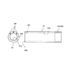
ノズル本体部22は、内部に流路32aが形成された円筒部32と、当該円筒部32の先端面32b(図3参照)に取り付けられるスリット形成部材34と、を有している。円筒部32の長手方向一端側(図3の右側の図における左側)の先端面32bには、3つのボルト孔BHが形成されている。当該3つのボルト孔BHは、当該先端面32bの円周方向のうち図3の上方部分に片寄って配置されている。また、円筒部32の長手方向他端側(図3の右側の図における右側)の外周面には雄ネジ32cが形成されている。雄ネジ32cには、ソケット23がネジ係合され、当該ソケット23を介してノズル本体部22にはホース70が接続される。さらに、流路32aは、図3に示すように、長手方向の一端側(図3の右側の図における左側)において内径が漸次縮小するテーパー形状に形成されている。言い換えると、流路32aは、長手方向の一端側(図3の右側の図における左側)に絞り部を有しているとも言える。
The
スリット形成部材34は、図4および図5に示すように、円板部34aと、当該円板部34aから軸線方向(図5の右側の図において左右方向)に突出状に設けられた突出部34bと、から構成されている。円板部34aは、本発明における「プレート部材」に対応し、突出部34bは、本発明における「接続部材」に対応する実施構成の一例である。
As shown in FIGS. 4 and 5, the
円板部34aの外径は、円筒部32の外径とほぼ同じ大きさに形成されている。突出部34bは、略扇状に形成されており、円板部34aに一体に設けられている。突出部34bの外径は円板部34aの外径と同じ大きさに形成されており、突出部34bの内径は円筒部32の先端面32b側の内径、即ち、テーパー形状に絞られた流路32aの流路径とほぼ同じ大きさとなるように形成されている。
The outer diameter of the
また、突出部34bには、円板部34aまで貫通する3つの貫通孔THが形成されている。当該3つの貫通孔THは、円筒部32の先端面32bに形成された3つのボルト孔BHと対応する位置関係に形成されている。即ち、当該3つのボルト孔BHから図示しないボルトを挿通して当該ボルトを円筒部32の3つのボルト孔BHに捩じ込むことによりスリット形成部材34が円筒部32に取り付けられる。こうしてスリット形成部材34が円筒部32に取り付けられることにより、ノズル本体部22の先端部(円筒部32の先端面32b側)にスリットSLが形成される。
Further, the projecting
スライドフランジ24は、図6に示すように、円筒状のスリーブ部24aと、当該スリーブ部24aの軸方向一端側(図6の中央の図において左側)に一体に接続されたラッパ状部24bと、から構成されており、ブッシュB(図2参照)を介してノズル本体部22の外周面に軸線方向に往復摺動自在に装着される。スライドフランジ24は、本発明における「方向変更部」に対応する実施構成の一例である。また、スリーブ部24aは、本発明における「摺動部」に対応し、ラッパ状部24bは、本発明における「拡径部」に対応する実施構成の一例である。
As shown in FIG. 6, the
スリーブ部24aの内径は、ノズル本体部22の円筒部32の外径よりも若干小さく形成されており、スリーブ部24aの内周面には軸線方向(図6の中央の図において左右方向)に互いに離れた位置にブッシュB(図2参照)が装着される2つの環状溝27が形成されている。
The inner diameter of the
ラッパ状部24bは、内外周面ともにスリーブ部24aの軸方向一端側(図6の中央の図において左側)から離れるに伴い漸次拡径するテーパー形状に形成されている。なお、ラッパ状部24bの内周面は、第1テーパー面28aおよび第2テーパー面28bの2段階テーパー形状に形成されている。具体的には、ラッパ状部24bの内周面のうち根本側(スリーブ部24aとの接続部寄り部分)にはテーパー角θ1を有する第1テーパー面28aが形成され、先端側(図6の中央の図において左端側)にはテーパー角θ2を有する第2テーパー面28bが形成されている。ここで、テーパー角θ1はテーパー角θ2よりも小さな角度となるように構成されている(θ1<θ2)。
The trumpet-shaped
こうして構成されコイル状線材CWRの軸線方向両側の各側に配置される各一対の洗浄用ノズル部材20は、図9に示すように、突出部34b同士が互いに向かい合う位置関係で設置される。言い換えると、スリットSL同士が互いに反対方向を向く位置関係で設置される。
As shown in FIG. 9, the pair of cleaning
アクチュエータ50は、図2に示すように、シリンダ50aと、ロッド50bと、を有しており、図示しないモータが駆動されることによってロッド50bが軸線方向に往復移動される電動シリンダとして構成されている。アクチュエータ50は、ロッド50bがブラケット52を介して洗浄用ノズル部材20のスライドフランジ24に接続されている。これにより、スライドフランジ24がノズル本体部22の外周面上を軸線方向に往復摺動される。
As shown in FIG. 2, the
制御装置60は、図示しないCPUを中心とするマイクロプロセッサとして構成されており、CPUの他に処理プログラムを記憶するROM(図示せず)と、データを一時的に記憶するRAM(図示せず)と、入出力ポートおよび通信ポート(いずれも図示せず)とを備えいる。制御装置60からは、アクチュエータ50への駆動信号などが出力ポートを介して出力されている。
The
次に、こうして構成された洗浄装置1の動作、特に、洗浄用ノズル部材20によってコイル状線材CWRの内周側に噴出される洗浄液としての洗浄水の様子について説明する。コイル状線材CWRの内周側の洗浄が開始されると、ポンプ40が駆動されてポンプ40からホース70を介して洗浄用ノズル部材20に洗浄水が供給される(図1参照)。洗浄用ノズル部材20に供給された洗浄水は、流路32aを通ってスリットSLから径方向に向かって噴出される。
Next, the operation of the thus configured cleaning
スリットSLから径方向に向かって噴出された洗浄水は、スライドフランジ24の内周面に衝突してその噴出方向が径方向と交差する方向、即ち、コイル状線材CWRの内周側に向かう方向に変更される。ここで、スライドフランジ24の内周面は2段階テーパー形状に構成されているため、洗浄水が第2テーパー面28bと衝突する際には、図11に示すように、洗浄水は第2テーパー面28bに誘導されて洗浄用ノズル部材20の軸線に対して角度θ2をもってコイル状線材CWRの内周側に向けて噴出される。一方、洗浄水が第1テーパー面28aと衝突する際には、図12に示すように、洗浄水は第1テーパー面28aに誘導されて洗浄用ノズル部材20の軸線に対して角度θ1をもってコイル状線材CWRの内周側に向けて噴出される。
The cleaning water ejected from the slit SL in the radial direction collides with the inner peripheral surface of the
即ち、制御装置60によってアクチュエータ50を駆動してスライドフランジ24をホース70に近づく方向に摺動させることによって、コイル状線材CWRの内周面のうち洗浄用ノズル部材20に近い側の内周面を重点的に洗浄することができ、制御装置60によってアクチュエータ50を駆動してスライドフランジ24をホース70から遠ざかる方向に摺動させることによって、コイル状線材CWRの内周面のうち洗浄用ノズル部材20から遠い側の内周面を重点的に洗浄することができる。
That is, by driving the
ここで、コイル状線材CWRの軸線方向両側に配置された洗浄用ノズル部材20においてスライドフランジ24の摺動方向を互いに逆方向となるようにアクチュエータ50を制御装置60によって駆動制御することによって、コイル状線材CWRの軸線方向両側に配置された洗浄用ノズル部材20から噴出される洗浄水がお互いに補完し合う相乗効果を発揮してコイル状線材CWRの長手方向全域に亘ってコイル状線材CWRの内周面を効果的に洗浄することができる。
Here, by driving and controlling the
具体的には、図13に示すように、コイル状線材CWRの軸線方向一端側(図13の左側)に配置された洗浄用ノズル部材20のスライドフランジ24をホース70から遠ざかる方向に摺動させると共に、コイル状線材CWRの軸線方向他端側(図13の右側)に配置された洗浄用ノズル部材20のスライドフランジ24をホース70に近づく方向に摺動させることによって、コイル状線材CWRの軸線方向他端側(図13の右側)寄りの内周面を重点的に洗浄することができる。
Specifically, as shown in FIG. 13, the
また、これとは逆に、図14に示すように、コイル状線材CWRの軸線方向一端側(図14の左側)に配置された洗浄用ノズル部材20のスライドフランジ24をホース70に近づく方向に摺動させると共に、コイル状線材CWRの軸線方向他端側(図14の右側)に配置された洗浄用ノズル部材20のスライドフランジ24をホース70から遠ざかる方向に摺動させることによって、コイル状線材CWRの軸線方向他端側(図14の左側)寄りの内周面を重点的に洗浄することができる。
On the contrary, as shown in FIG. 14, the
さらに、図15に示すように、コイル状線材CWRの軸線方向一端側(図15の左側)に配置された洗浄用ノズル部材20のスライドフランジ24と、コイル状線材CWRの軸線方向他端側(図15の右側)に配置された洗浄用ノズル部材20のスライドフランジ24と、洗浄用ノズル部材20の軸線方向においてほぼ同じ位置となるよう摺動させることによって、コイル状線材CWRの軸線方向の中央部近傍の内周面を重点的に洗浄することができる。
Further, as shown in FIG. 15, the
なお、洗浄水をスリットSLによって径方向に噴出させる構成であるため、洗浄水を連続した扇形状に噴出させることができる。これにより、コイル状線材CWRの内周面の円周方向にムラなく洗浄水を噴き付けることができる。 Since the cleaning water is ejected in the radial direction by the slit SL, the cleaning water can be ejected in a continuous fan shape. As a result, the cleaning water can be sprayed evenly in the circumferential direction of the inner peripheral surface of the coil-shaped wire CWR.
また、スリットSLが互いに反対方向を向くように洗浄用ノズル部材20が設置される構成であるため、図10に示すように、並列配置された洗浄用ノズル部材20から噴出される洗浄水同士が互いに干渉することを抑制することができる。これにより、洗浄性能の低下を抑制することができる。
Further, since the cleaning
さらに、洗浄用ノズル部材20が、コイル状線材CWRの軸中心Pよりも鉛直方向において上側に配置される構成であるため、洗浄用ノズル部材20から噴出される洗浄水のうち上方に向かって噴出される洗浄水が、拡散幅が大きくなる前にコイル状線材CWRに噴き付けることができる。これにより、洗浄液の上方への噴き上がりを抑制することができる。
Further, since the cleaning
以上、本発明の実施の形態に係る洗浄用ノズル部材20を備える洗浄装置1によれば、洗浄用ノズル部材20をコイル状線材CWRの内外に往復移動させなくても、コイル状線材CWRの内周面を効果的に洗浄することができるため、洗浄用ノズル部材20を往復移動させるためのスペースが必要なくなり、装置を設置するための必要スペースを大幅に縮小することができる。
As described above, according to the
本実施の形態では、コイル状線材CWRの軸線方向両側の各側それぞれに2つの洗浄用ノズル部材20を配置する構成としたが、これに限らない。コイル状線材CWRの軸線方向両側の各側それぞれに洗浄用ノズル部材20を1つのみ配置する構成としても良いし、3つ以上配置する構成としても良い。また、コイル状線材CWRの軸線方向両側の各側に配置する洗浄用ノズル部材20の個数を変えても良い。
In the present embodiment, two cleaning
本実施の形態では、コイル状線材CWRの軸線方向両側に洗浄用ノズル部材20を配置する構成としたが、コイル状線材CWRの軸線方向の一方側のみに洗浄用ノズル部材20を配置する構成としても良い。
In the present embodiment, the cleaning
本実施の形態では、コイル状線材CWRの軸中心Pよりも鉛直方向において上側に洗浄用ノズル部材20を配置する構成としたが、これに限らない。コイル状線材CWRの軸中心Pと同じ高さ位置に洗浄用ノズル部材20を配置する構成としても良いし、コイル状線材CWRの軸中心Pよりも鉛直方向において下側に洗浄用ノズル部材20を配置する構成としても良い。また、コイル状線材CWRの軸中心Pを通る仮想鉛直線VLを挟んで一方側に配置された洗浄用ノズル部材20と当該仮想鉛直線VLを挟んで他方側に配置された洗浄用ノズル部材20とが異なる高さ位置に配置される構成としても良い。
In the present embodiment, the cleaning
本実施の形態では、スリット形成部材34は、円板部34aと突出部34bとが一体に形成される構成としたが、円板部34aと突出部34bとは別体であっても良い。
In the present embodiment, the
本実施の形態では、スリット形成部材34の円筒部32への取り付け位置は固定としたが、これに限らない。例えば、円筒部32の先端面32bに3つ以上のボルト孔BHを形成して、当該ボルト孔BHの孔位置に合せてスリット形成部材34の取り付け位置を調整可能な構成としも良い。
In the present embodiment, the attachment position of the
本実施の形態では、ノズル本体部22の軸線方向から見た場合に、スリットSLが略扇状を有する構成としたが、これに限らない。例えば、図16の変形例の洗浄用ノズル部材120に例示するように、ノズル本体部122の軸線方向から見た場合に、スリットSLが円環状を有する構成としても良い。
In the present embodiment, the slit SL has a substantially fan shape when viewed from the axial direction of the
変形例の洗浄用ノズル部材120は、図16に示すように、ノズル本体部122の円筒部132の流路132a内に十字ブラケット136をボルトによって取り付けると共に、当該十字ブラケット136に支柱ブラケット138をボルトによって取り付け、当該支柱ブラケット138に円板部134aをボルトによって取り付ける構成である。これにより、円筒部32の先端面132bと円板部134aとの間に、円筒部132の軸線方向から見た場合に円環状のスリットSLが形成される。なお、円板部134aは、円筒部132の外径とほぼ同じ外径を有する円板として構成されている。円板部134a、十字ブラケット136および支柱ブラケット138によってスリット形成部材134が構成される。
In the
本実施の形態では、スライドフランジ24の内周面を第1テーパー面28aおよび第2テーパー面28bの2段階テーパー形状に形成する構成としたが、これに限らない。例えば、スライドフランジ24の内周面を1段階のテーパー形状に形成する構成としても良いし、スライドフランジ24の内周面を3段階以上のテーパー形状に形成する構成としても良い。
In the present embodiment, the inner peripheral surface of the
本実施の形態では、コイル状線材CWRの軸線方向一端側に配置された洗浄用ノズル部材20と、コイル状線材CWRの軸線方向他端側に配置された洗浄用ノズル部材20のスライドフランジ24と、では、摺動方向が互いに逆方向となるようにアクチュエータ50を制御装置60によって駆動制御する構成としたが、コイル状線材CWRの軸線方向一端側に配置された洗浄用ノズル部材20と、コイル状線材CWRの軸線方向他端側に配置された洗浄用ノズル部材20のスライドフランジ24と、で摺動方向が互いに同じ方向となるようにアクチュエータ50を制御装置60によって駆動制御する構成としても良い。
In the present embodiment, the cleaning
本実施の形態では、スライドフランジ24のラッパ状部24bの内周面には、何も設けない構成としたが、図17に示す変形例のスライドフランジ224に例示するように、スライドフランジ224のラッパ状部224bの内周面には複数の整流リブ229を設ける構成としても良い。当該構成によれば、整合リブ229によってラッパ状部224bの内周面に衝突した洗浄水がコイル状線材CWRの内周側に向かう方向に整流されるため、より効率的にコイル状線材CWRの内周面の洗浄を行うことができる。
In the present embodiment, nothing is provided on the inner peripheral surface of the trumpet-shaped
本実施形態は、本発明を実施するための形態の一例を示すものである。したがって、本発明は、本実施形態の構成に限定されるものではない。 The present embodiment shows an example of a mode for carrying out the present invention. Therefore, the present invention is not limited to the configuration of this embodiment.
1 洗浄装置(コイル状線材の洗浄装置)
20 洗浄用ノズル部材(コイル状線材の洗浄用ノズル部材)
22 ノズル本体部(ノズル本体部)
24 スライドフランジ(方向変更部)
24a スリーブ部(摺動部)
24b ラッパ状部(拡径部)
27 環状溝
28a 第1テーパー面(テーパー面)
28b 第2テーパー面(テーパー面)
32 円筒部
32a 流路(流路)
32b 先端面
32c 雄ネジ
34 スリット形成部材
34a 円板部(プレート部材)
34b 突出部(接続部材)
40 ポンプ(洗浄液供給装置)
50 アクチュエータ(アクチュエータ)
50a シリンダ
50b ロッド
52 ブラケット
60 制御装置(制御装置)
70 ホース(管路部材)
90 L形フック
120 洗浄用ノズル部材(コイル状線材の洗浄用ノズル部材)
122 ノズル本体部(ノズル本体部)
132 円筒部
132a 流路(流路)
132b 先端面
134 スリット形成部材
134a 円板部(プレート部材)
136 十字ブラケット(接続部材)
138 支柱ブラケット(接続部材)
224 スライドフランジ(方向変更部)
224a スリーブ部(摺動部)
224b ラッパ状部(拡径部)
229 整流リブ
CWR コイル状線材(コイル状線材)
P コイル状線材の軸中心
VL 仮想鉛直線
BH ボルト孔
TH 貫通孔
SL スリット(スリット)
B ブッシュ
θ1 テーパー角
θ2 テーパー角
1 Cleaning device (coiled wire cleaning device)
20 Cleaning nozzle member (coil-shaped wire cleaning nozzle member)
22 Nozzle body (nozzle body)
24 Slide flange (direction change part)
24a Sleeve part (sliding part)
24b Trumpet-shaped part (expanded part)
27
28b Second taper surface (taper surface)
32
32b Tip surface
34b Projection (connecting member)
40 pumps (cleaning liquid supply device)
50 actuators
70 Hose (pipe member)
90 L-shaped
122 Nozzle body (nozzle body)
132
136 cross bracket (connecting member)
138 Support bracket (connecting member)
224 Slide flange (direction change part)
224a Sleeve part (sliding part)
224b Trumpet-shaped part (expanded part)
229 Straightening rib CWR Coiled wire (coiled wire)
P Shaft center of coiled wire VL Virtual vertical line BH Bolt hole TH Through hole SL Slit (slit)
B Bush θ1 taper angle θ2 taper angle
Claims (12)
内部に前記洗浄液が流れる流路を有し、該洗浄液を径方向に噴出するよう構成された筒状のノズル本体部と、
該ノズル本体部から径方向に噴出される前記洗浄液の噴出方向を前記径方向から該径方向に交差する方向に連続的に変更可能な方向変更部と、
を備えるコイル状線材の洗浄用ノズル部材。
A nozzle member for cleaning a coiled wire, which sprays a cleaning liquid for cleaning the inner peripheral side of the coiled wire,
A tubular nozzle main body having a flow passage in which the cleaning liquid flows, and configured to eject the cleaning liquid in a radial direction;
A direction changing unit capable of continuously changing the jetting direction of the cleaning liquid jetted radially from the nozzle body from the radial direction to a direction intersecting the radial direction;
A nozzle member for cleaning a coiled wire rod, comprising:
請求項1に記載のコイル状線材の洗浄用ノズル部材。 The nozzle main body has a slit cut out in a direction intersecting the axial direction of the nozzle main body so as to communicate with the flow path, and the cleaning liquid is ejected in the radial direction by the slit. The nozzle member for cleaning a coiled wire according to claim 1.
前記ノズル本体部の先端と前記プレート部材との間に形成される隙間によって前記スリットが形成されるよう構成されている
請求項2に記載のコイル状線材の洗浄用ノズル部材。 The nozzle body is configured such that the flow path opens at the tip of the nozzle body, and the plate member is arranged to face the opening at a position separated from the tip of the nozzle body by a predetermined distance. And a connecting member for connecting the plate member to the tip of the nozzle body,
The nozzle member for cleaning a coiled wire rod according to claim 2, wherein the slit is formed by a gap formed between the tip of the nozzle body and the plate member.
請求項3に記載のコイル状線材の洗浄用ノズル部材。 The nozzle member for cleaning a coiled wire according to claim 3, wherein the connecting member is configured to close a part of the gap.
前記ノズル本体部から径方向に噴出された前記洗浄液が前記拡径部の内周面に衝突することによって前記洗浄液の噴出方向が前記径方向から該径方向に交差する方向に変更されるよう構成されている
請求項1ないし4のいずれか1項に記載のコイル状線材の洗浄用ノズル部材。
The direction changing portion is a tubular sliding portion configured to be slidable on the outer peripheral surface of the nozzle main body portion in the axial direction, and is integrally connected to the sliding portion to move away from the sliding portion. Along with the taper shape, the inner diameter is gradually increased, and the enlarged diameter portion has a
The cleaning liquid ejected from the nozzle body in the radial direction collides with the inner peripheral surface of the expanded diameter portion so that the ejection direction of the cleaning liquid is changed from the radial direction to the direction intersecting the radial direction. The nozzle member for cleaning a coiled wire according to any one of claims 1 to 4.
請求項5に記載の洗浄用ノズル部材。 The cleaning nozzle member according to claim 5, wherein the enlarged diameter portion is configured to include a plurality of tapered surfaces having different taper angles.
前記方向変更部を駆動するアクチュエータと、
該アクチュエータの駆動を制御する制御装置と、
該コイル状線材の洗浄用ノズル部材に前記洗浄液を供給する洗浄液供給装置と、
前記コイル状線材の洗浄用ノズル部材と前記洗浄液供給装置とを接続する管路部材と、
を備える
コイル状線材の洗浄装置。 A nozzle member for cleaning a coil-shaped wire according to any one of claims 1 to 6,
An actuator that drives the direction changing unit,
A control device for controlling the drive of the actuator;
A cleaning liquid supply device for supplying the cleaning liquid to the nozzle member for cleaning the coiled wire,
A conduit member that connects the cleaning nozzle member for the coiled wire and the cleaning liquid supply device;
A cleaning device for coiled wire.
請求項7に記載のコイル状線材の洗浄装置。
The nozzle member for cleaning the coiled wire is arranged on both left and right sides of an imaginary vertical line passing through the axial center of the coiled wire when the coiled wire is viewed from the axial direction. The coil-shaped wire cleaning device according to claim 7, further comprising a cleaning nozzle member.
請求項8に記載のコイル状線材の洗浄装置。 The first and second cleaning nozzle members are arranged in an extending direction of a virtual straight line connecting at least axial centers of the first and second cleaning nozzle members so that the cleaning liquids ejected in the radial direction do not interfere with each other. The coil-shaped wire cleaning device according to claim 8, wherein the cleaning liquid is not ejected.
請求項7ないし9のいずれか1項に記載のコイル状線材の洗浄装置。 The nozzle member for cleaning the coiled wire is arranged at a position higher than an axial center of the coiled wire when the coiled wire is viewed from the axial direction. The cleaning device for coiled wire according to.
請求項7ないし10のいずれか1項に記載のコイル状線材の洗浄装置。 11. The cleaning device for a coiled wire rod according to claim 7, wherein the nozzle member for cleaning the coiled wire rod is arranged on both sides of the coiled wire rod in an axial direction with the coil wire rod interposed therebetween. ..
請求項11に記載のコイル状線材の洗浄装置。 The control device includes a driving direction of the direction changing portion of the cleaning nozzle member arranged on one side in the axial direction of the coiled wire, and the cleaning nozzle arranged on the other side in the axial direction of the coiled wire. The cleaning device for a coiled wire according to claim 11, wherein the actuator is controlled so that a driving direction of the direction changing portion of the member is different.
Priority Applications (1)
| Application Number | Priority Date | Filing Date | Title |
|---|---|---|---|
| JP2016039435A JP6694227B2 (en) | 2016-03-01 | 2016-03-01 | Coil-shaped wire rod cleaning nozzle member and coil-shaped wire rod cleaning device including the same |
Applications Claiming Priority (1)
| Application Number | Priority Date | Filing Date | Title |
|---|---|---|---|
| JP2016039435A JP6694227B2 (en) | 2016-03-01 | 2016-03-01 | Coil-shaped wire rod cleaning nozzle member and coil-shaped wire rod cleaning device including the same |
Publications (2)
| Publication Number | Publication Date |
|---|---|
| JP2017155284A JP2017155284A (en) | 2017-09-07 |
| JP6694227B2 true JP6694227B2 (en) | 2020-05-13 |
Family
ID=59808086
Family Applications (1)
| Application Number | Title | Priority Date | Filing Date |
|---|---|---|---|
| JP2016039435A Active JP6694227B2 (en) | 2016-03-01 | 2016-03-01 | Coil-shaped wire rod cleaning nozzle member and coil-shaped wire rod cleaning device including the same |
Country Status (1)
| Country | Link |
|---|---|
| JP (1) | JP6694227B2 (en) |
Families Citing this family (3)
| Publication number | Priority date | Publication date | Assignee | Title |
|---|---|---|---|---|
| CN111151490B (en) * | 2019-12-31 | 2025-01-07 | 南京艾科天喜机电设备有限公司 | A high-pressure annular sprayer for metal wire processing and production |
| CN113546883A (en) * | 2020-04-26 | 2021-10-26 | 苏州市珺优电子科技有限公司 | Wire cleaning device |
| US20230090908A1 (en) * | 2021-09-23 | 2023-03-23 | GM Global Technology Operations LLC | Paint spray nozzle for a paint spray system |
Family Cites Families (11)
| Publication number | Priority date | Publication date | Assignee | Title |
|---|---|---|---|---|
| JPS5220417A (en) * | 1975-08-11 | 1977-02-16 | Wagner Josef | Protectors for flat type atmizer nozzles |
| JPS52110609U (en) * | 1976-02-19 | 1977-08-23 | ||
| JPS5981995U (en) * | 1982-11-24 | 1984-06-02 | 安藤 津々子 | cleaning equipment nozzle |
| JPS5993667U (en) * | 1982-12-07 | 1984-06-25 | 栃木富士産業株式会社 | spray nozzle |
| GB2157591B (en) * | 1984-04-19 | 1987-11-25 | Spraying Systems Co | Air-assisted spray nozzle |
| JPH0121011Y2 (en) * | 1984-12-13 | 1989-06-23 | ||
| JPH07316855A (en) * | 1994-05-20 | 1995-12-05 | Daido Steel Co Ltd | Coil wire cleaning device |
| JPH1099799A (en) * | 1996-09-27 | 1998-04-21 | Showa:Kk | Cleaning equipment |
| JP4338999B2 (en) * | 2003-03-25 | 2009-10-07 | セイコーインスツル株式会社 | Parts cleaning method and apparatus |
| JP2005095843A (en) * | 2003-09-24 | 2005-04-14 | Akio Kobayashi | Herbicide stable sprayer for protecting crop to limitation |
| JP5807968B2 (en) * | 2012-11-05 | 2015-11-10 | 株式会社五十鈴製作所 | High pressure water washing equipment for wire coil |
-
2016
- 2016-03-01 JP JP2016039435A patent/JP6694227B2/en active Active
Also Published As
| Publication number | Publication date |
|---|---|
| JP2017155284A (en) | 2017-09-07 |
Similar Documents
| Publication | Publication Date | Title |
|---|---|---|
| JP6694227B2 (en) | Coil-shaped wire rod cleaning nozzle member and coil-shaped wire rod cleaning device including the same | |
| WO2019125665A1 (en) | Spray nozzle and method | |
| CN104043543A (en) | Splashless spray head | |
| WO2017094042A1 (en) | Washing nozzle for machine tool and said machine tool | |
| CN104994961B (en) | Coating agent pump and cleaning method of coating agent pump | |
| US12251719B2 (en) | Nozzle assembly for delivering an oscillating spray pattern | |
| JP4774444B2 (en) | Cleaning assembly | |
| CN106030000A (en) | Nozzle assembly and bidet device including same | |
| CN216306346U (en) | Cleaning mechanism, fan cleaning device with same and range hood | |
| JP5827105B2 (en) | Cleaning nozzle and hose cleaning method | |
| JP6624286B2 (en) | Hole inner surface processing apparatus and hole inner surface processing method | |
| JP6268185B2 (en) | Fuel injection valve | |
| KR101285318B1 (en) | Remote blower pipe | |
| JP2005177607A (en) | Rotary atomization coating equipment | |
| JP7155897B2 (en) | Ejector | |
| CN105019060B (en) | Glass fibre flings rifle | |
| CN218751398U (en) | Cleaning unmanned aerial vehicle with adjustable water spray width | |
| JP7138370B1 (en) | Anti-scattering nozzle device | |
| US20160199855A1 (en) | Nozzle assembly capable of performing suction and high pressure blowing | |
| JP6380154B2 (en) | Cleaning nozzle and cleaning device | |
| KR102961166B1 (en) | Cleaning apparatus | |
| CN218573972U (en) | Centrifugal atomization device | |
| US20090113642A1 (en) | Device for washing liquid turbulation for rotary jet heads, especially water-cleaning machines | |
| KR101595418B1 (en) | Injection nozzles for dry type cleaning apparatus | |
| CN222153090U (en) | Gear shaft cleaning assembly |
Legal Events
| Date | Code | Title | Description |
|---|---|---|---|
| A521 | Request for written amendment filed |
Free format text: JAPANESE INTERMEDIATE CODE: A523 Effective date: 20180329 |
|
| A621 | Written request for application examination |
Free format text: JAPANESE INTERMEDIATE CODE: A621 Effective date: 20190213 |
|
| A977 | Report on retrieval |
Free format text: JAPANESE INTERMEDIATE CODE: A971007 Effective date: 20191209 |
|
| A131 | Notification of reasons for refusal |
Free format text: JAPANESE INTERMEDIATE CODE: A131 Effective date: 20191225 |
|
| A521 | Request for written amendment filed |
Free format text: JAPANESE INTERMEDIATE CODE: A523 Effective date: 20191225 |
|
| TRDD | Decision of grant or rejection written | ||
| A01 | Written decision to grant a patent or to grant a registration (utility model) |
Free format text: JAPANESE INTERMEDIATE CODE: A01 Effective date: 20200416 |
|
| A61 | First payment of annual fees (during grant procedure) |
Free format text: JAPANESE INTERMEDIATE CODE: A61 Effective date: 20200416 |
|
| R150 | Certificate of patent or registration of utility model |
Ref document number: 6694227 Country of ref document: JP Free format text: JAPANESE INTERMEDIATE CODE: R150 |
|
| R250 | Receipt of annual fees |
Free format text: JAPANESE INTERMEDIATE CODE: R250 |
|
| R250 | Receipt of annual fees |
Free format text: JAPANESE INTERMEDIATE CODE: R250 |