以下、本発明の実施形態について、添付図面を参照して説明する。まず、図1から図88を参照し、第1実施形態として、本発明をパチンコ遊技機(以下、単に「パチンコ機」という)10に適用した場合の一実施形態について説明する。図1は、第1実施形態におけるパチンコ機10の正面図であり、図2はパチンコ機10の遊技盤13の正面図であり、図3はパチンコ機10の背面図である。
Hereinafter, embodiments of the present invention will be described with reference to the accompanying drawings. First, with reference to FIG. 1 to FIG. 88, one embodiment in which the present invention is applied to a pachinko gaming machine (hereinafter, simply referred to as a “pachinko machine”) 10 will be described as a first embodiment. FIG. 1 is a front view of a pachinko machine 10 according to the first embodiment, FIG. 2 is a front view of a game board 13 of the pachinko machine 10, and FIG. 3 is a rear view of the pachinko machine 10.
図1に示すように、パチンコ機10は、略矩形状に組み合わせた木枠により外殻が形成される外枠11と、その外枠11と略同一の外形形状に形成され外枠11に対して開閉可能に支持された内枠12とを備えている。外枠11には、内枠12を支持するために正面視(図1参照)左側の上下2カ所に金属製のヒンジ18が取り付けられ、そのヒンジ18が設けられた側を開閉の軸として内枠12が正面手前側へ開閉可能に支持されている。
As shown in FIG. 1, the pachinko machine 10 has an outer frame 11 in which an outer shell is formed by a wooden frame combined in a substantially rectangular shape, and an outer frame 11 having substantially the same outer shape as that of the outer frame 11. And an inner frame 12 that is openably and closably supported. To support the inner frame 12, metal hinges 18 are attached to the outer frame 11 at two upper and lower positions on the left side in a front view (see FIG. 1), and the side on which the hinge 18 is provided serves as an opening / closing shaft. The frame 12 is supported to be openable and closable toward the front side.
内枠12には、多数の釘や入賞口63,64等を有する遊技盤13(図2参照)が裏面側から着脱可能に装着される。この遊技盤13の前面を球(遊技球)が流下することにより弾球遊技が行われる。なお、内枠12には、球を遊技盤13の前面領域に発射する球発射ユニット112a(図4参照)やその球発射ユニット112aから発射された球を遊技盤13の前面領域まで誘導する発射レール(図示せず)等が取り付けられている。
A game board 13 (see FIG. 2) having a large number of nails, winning holes 63, 64, etc. is detachably attached to the inner frame 12 from the back side. A ball game is performed by flowing a ball (game ball) on the front surface of the game board 13. In addition, in the inner frame 12, a ball launch unit 112a (see FIG. 4) that launches a ball to the front area of the game board 13 and a launch that guides the ball launched from the ball launch unit 112a to the front area of the game board 13. Rails (not shown) and the like are attached.
内枠12の前面側には、その前面上側を覆う前面枠14と、その下側を覆う下皿ユニット15とが設けられている。前面枠14及び下皿ユニット15を支持するために正面視(図1参照)左側の上下2カ所に金属製のヒンジ19が取り付けられ、そのヒンジ19が設けられた側を開閉の軸として前面枠14及び下皿ユニット15が正面手前側へ開閉可能に支持されている。なお、内枠12の施錠と前面枠14の施錠とは、シリンダ錠20の鍵穴21に専用の鍵を差し込んで所定の操作を行うことでそれぞれ解除される。
On the front side of the inner frame 12, a front frame 14 that covers the upper side of the front surface and a lower plate unit 15 that covers the lower side thereof are provided. To support the front frame 14 and the lower tray unit 15, metal hinges 19 are attached at two upper and lower positions on the left side in front view (see FIG. 1), and the side provided with the hinges 19 serves as an opening / closing shaft. The lower plate unit 14 and the lower plate unit 15 are supported to be openable and closable toward the front front side. The locking of the inner frame 12 and the locking of the front frame 14 are released by inserting a dedicated key into the keyhole 21 of the cylinder lock 20 and performing a predetermined operation.
前面枠14は、装飾用の樹脂部品や電気部品等を組み付けたものであり、その略中央部には略楕円形状に開口形成された窓部14cが設けられている。前面枠14の裏面側には2枚の板ガラスを有するガラスユニット16が配設され、そのガラスユニット16を介して遊技盤13の前面がパチンコ機10の正面側に視認可能となっている。
The front frame 14 is assembled with a decorative resin component, an electrical component, and the like, and a window portion 14c having a substantially elliptical opening is provided at a substantially central portion thereof. A glass unit 16 having two glass plates is arranged on the back surface side of the front frame 14, and the front surface of the game board 13 can be visually recognized on the front surface side of the pachinko machine 10 through the glass unit 16.
前面枠14には、球を貯留する上皿17が前方へ張り出して上面を開放した略箱状に形成されており、この上皿17に賞球や貸出球などが排出される。上皿17の底面は正面視(図1参照)右側に下降傾斜して形成され、その傾斜により上皿17に投入された球が球発射ユニット112a(図4参照)へと案内される。また、上皿17の上面には、枠ボタン22が設けられている。この枠ボタン22は、例えば、第3図柄表示装置81(図2参照)で表示される演出のステージを変更したり、スーパーリーチの演出内容を変更したりする場合などに、遊技者により操作される。
On the front frame 14, an upper plate 17 for storing balls is formed in a substantially box shape with its front surface protruding and its upper surface opened, and prize balls, rental balls, etc. are discharged to the upper plate 17. The bottom surface of the upper plate 17 is formed to be inclined downward to the right side in a front view (see FIG. 1), and the ball introduced into the upper plate 17 is guided to the ball firing unit 112a (see FIG. 4) by the inclination. A frame button 22 is provided on the upper surface of the upper plate 17. The frame button 22 is operated by the player, for example, when changing the stage of the effect displayed on the third symbol display device 81 (see FIG. 2) or when changing the effect contents of the super reach. It
前面枠14には、その周囲(例えばコーナー部分)に各種ランプ等の発光手段が設けられている。これら発光手段は、大当たり時や所定のリーチ時等における遊技状態の変化に応じて、点灯又は点滅することにより発光態様が変更制御され、遊技中の演出効果を高める役割を果たす。窓部14cの周縁には、LED等の発光手段を内蔵した電飾部29〜33が設けられている。パチンコ機10においては、これら電飾部29〜33が大当たりランプ等の演出ランプとして機能し、大当たり時やリーチ演出時等には内蔵するLEDの点灯や点滅によって各電飾部29〜33が点灯または点滅して、大当たり中である旨、或いは大当たり一歩手前のリーチ中である旨が報知される。また、前面枠14の正面視(図1参照)左上部には、LED等の発光手段が内蔵され賞球の払い出し中とエラー発生時とを表示可能な表示ランプ34が設けられている。
The front frame 14 is provided with light emitting means such as various lamps around the front frame 14 (for example, a corner portion). These light emitting means change the light emitting mode by lighting or blinking according to the change of the game state at the time of a big hit or a predetermined reach, and play a role of enhancing the effect effect during the game. On the periphery of the window portion 14c, there are provided electric decoration portions 29 to 33 having a light emitting means such as an LED built therein. In the pachinko machine 10, these illumination parts 29 to 33 function as a production lamp such as a jackpot lamp, and when the jackpot or reach production is performed, each illumination portion 29 to 33 is turned on by turning on or blinking the built-in LED. Alternatively, it flashes to notify that the jackpot is in the midst of hitting, or that the reach is one step ahead of the jackpot. A display lamp 34 is provided at the upper left portion of the front frame 14 when viewed from the front (see FIG. 1). The display lamp 34 has a built-in light emitting means such as an LED and can display whether a prize ball is being paid out or an error has occurred.
また、右側の電飾部32下側には、前面枠14の裏面側を視認できるように裏面側より透明樹脂を取り付けて小窓35が形成され、遊技盤13前面の貼着スペースK1(図2参照)に貼付される証紙等がパチンコ機10の前面から視認可能とされている。また、パチンコ機10においては、より煌びやかさを醸し出すために、電飾部29〜33の周りの領域にクロムメッキを施したABS樹脂製のメッキ部材36が取り付けられている。
In addition, a small window 35 is formed on the lower side of the right side illumination portion 32 so that the back side of the front frame 14 can be visually recognized, and a small window 35 is formed, and a pasting space K1 on the front side of the game board 13 (FIG. The certificate or the like attached to (see 2) is visible from the front of the pachinko machine 10. Further, in the pachinko machine 10, a plating member 36 made of ABS resin plated with chrome is attached to a region around the electric decorations 29 to 33 in order to bring out more glitter.
窓部14cの下方には、貸球操作部40が配設されている。貸球操作部40には、度数表示部41と、球貸しボタン42と、返却ボタン43とが設けられている。パチンコ機10の側方に配置されるカードユニット(球貸しユニット)(図示せず)に紙幣やカード等を投入した状態で貸球操作部40が操作されると、その操作に応じて球の貸出が行われる。具体的には、度数表示部41はカード等の残額情報が表示される領域であり、内蔵されたLEDが点灯して残額情報として残額が数字で表示される。球貸しボタン42は、カード等(記録媒体)に記録された情報に基づいて貸出球を得るために操作されるものであり、カード等に残額が存在する限りにおいて貸出球が上皿17に供給される。返却ボタン43は、カードユニットに挿入されたカード等の返却を求める際に操作される。なお、カードユニットを介さずに球貸し装置等から上皿17に球が直接貸し出されるパチンコ機、いわゆる現金機では貸球操作部40が不要となるが、この場合には、貸球操作部40の設置部分に飾りシール等を付加して部品構成は共通のものとしても良い。カードユニットを用いたパチンコ機と現金機との共通化を図ることができる。
A ball rental operating unit 40 is arranged below the window 14c. The ball lending operation unit 40 is provided with a frequency display unit 41, a ball lending button 42, and a return button 43. When the ball rental operation unit 40 is operated in the state where bills, cards, etc. are inserted into a card unit (ball lending unit) (not shown) arranged on the side of the pachinko machine 10, the ball Lending is done. Specifically, the frequency display unit 41 is an area in which the balance information of a card or the like is displayed, and the built-in LED lights to display the balance as a number as the balance information. The ball lending button 42 is operated to obtain a lending ball based on information recorded on a card or the like (recording medium), and the lending ball is supplied to the upper plate 17 as long as there is a balance on the card or the like. To be done. The return button 43 is operated when requesting the return of a card or the like inserted in the card unit. It should be noted that the ball rental operation unit 40 is not required in a pachinko machine, which is a cash machine in which balls are lent directly to the upper plate 17 from a ball lending device or the like without using a card unit, but in this case, the ball rental operation unit 40 is used. It is also possible to add a decorative seal or the like to the installation portion of to make the parts configuration common. A pachinko machine using a card unit and a cash machine can be shared.
上皿17の下側に位置する下皿ユニット15には、その左側に上皿17に貯留しきれなかった球を貯留するための下皿50が上面を開放した略箱状に形成されている。下皿50の右側には、球を遊技盤13の前面へ打ち込むために遊技者によって操作される操作ハンドル51が配設される。
On the lower plate unit 15 located below the upper plate 17, a lower plate 50 for storing balls that could not be stored in the upper plate 17 is formed on the left side of the lower plate unit 15 in a substantially box-like shape with an open upper surface. . On the right side of the lower plate 50, an operation handle 51 operated by the player to drive the ball into the front surface of the game board 13 is provided.
操作ハンドル51の内部には、球発射ユニット112aの駆動を許可するためのタッチセンサ51aと、押下操作している期間中には球の発射を停止する発射停止スイッチ51bと、操作ハンドル51の回動操作量(回動位置)を電気抵抗の変化により検出する可変抵抗器(図示せず)などが内蔵されている。操作ハンドル51が遊技者によって右回りに回動操作されると、タッチセンサ51aがオンされると共に可変抵抗器の抵抗値が回動操作量に対応して変化し、その可変抵抗器の抵抗値に対応した強さ(発射強度)で球が発射され、これにより遊技者の操作に対応した飛び量で遊技盤13の前面へ球が打ち込まれる。また、操作ハンドル51が遊技者により操作されていない状態においては、タッチセンサ51aおよび発射停止スイッチ51bがオフとなっている。
Inside the operation handle 51, a touch sensor 51a for permitting the drive of the ball firing unit 112a, a firing stop switch 51b for stopping the firing of the ball during the pressing operation, and a rotation of the operation handle 51. A variable resistor (not shown) for detecting a dynamic operation amount (rotational position) by a change in electric resistance is incorporated. When the operation handle 51 is rotated clockwise by the player, the touch sensor 51a is turned on and the resistance value of the variable resistor changes in accordance with the amount of rotation operation, and the resistance value of the variable resistor is changed. The ball is fired with a strength (firing strength) corresponding to, and thereby the ball is driven into the front surface of the game board 13 with a jump amount corresponding to the operation of the player. Further, when the operation handle 51 is not operated by the player, the touch sensor 51a and the firing stop switch 51b are off.
下皿50の正面下方部には、下皿50に貯留された球を下方へ排出する際に操作するための球抜きレバー52が設けられている。この球抜きレバー52は、常時、正面方向に付勢されており、その付勢に抗して背面方向へスライドさせることにより、下皿50の底面に形成された底面口が開口して、その底面口から球が自然落下して排出される。この球抜きレバー54bの操作は、通常、下皿50の下方に下皿50から排出された球を受け取る箱(一般に「千両箱」と称される)を置いた状態で行われる。
At the lower part of the front surface of the lower plate 50, there is provided a ball removing lever 52 for operating when the balls stored in the lower plate 50 are discharged downward. The ball-pulling lever 52 is always biased in the front direction, and by sliding the ball-removing lever 52 in the rear direction against the bias, the bottom opening formed on the bottom surface of the lower plate 50 opens, and The sphere falls from the bottom opening and is discharged. The operation of the ball removing lever 54b is usually performed with a box (generally referred to as a "thousand box") placed below the lower plate 50 for receiving the balls discharged from the lower plate 50.
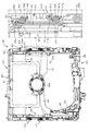
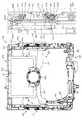
図2に示すように、遊技盤13は、正面視略正方形状に切削加工したベース板60に、球案内用の多数の釘(図示せず)や風車の他、レール61,62、一般入賞口63、第1入賞口64、第2入賞口640、可変入賞装置65、スルーゲート67、可変表示装置ユニット80等を組み付けて構成され、その周縁部が内枠12(図1参照)の裏面側に取り付けられる。ベース板60は光透過性の樹脂材料からなり、その正面側からベース板60の背面側に配設された各種構造体を遊技者に視認させることが可能に形成される。一般入賞口63、第1入賞口64、第2入賞口640、可変入賞装置65、可変表示装置ユニット80は、ルータ加工によってベース板60に形成された貫通穴に配設され、遊技盤13の前面側からタッピングネジ等により固定されている。
As shown in FIG. 2, the game board 13 includes a base plate 60 that is cut into a substantially square shape in a front view, a large number of nails (not shown) for guiding balls, a windmill, rails 61 and 62, and general prizes. The mouth 63, the first winning opening 64, the second winning opening 640, the variable winning device 65, the through gate 67, the variable display device unit 80 and the like are assembled, and the peripheral portion thereof is the back surface of the inner frame 12 (see FIG. 1). Mounted on the side. The base plate 60 is made of a light-transmissive resin material, and is formed so that a player can visually recognize various structures arranged on the back side of the base plate 60 from the front side thereof. The general winning opening 63, the first winning opening 64, the second winning opening 640, the variable winning device 65, and the variable display device unit 80 are disposed in through holes formed in the base plate 60 by router processing. It is fixed with a tapping screw or the like from the front side.
遊技盤13の前面中央部分は、前面枠14の窓部14c(図1参照)を通じて内枠12の前面側から視認することができる。以下に、主に図2を参照して、遊技盤13の構成について説明する。
The front center portion of the game board 13 can be viewed from the front side of the inner frame 12 through the window 14c (see FIG. 1) of the front frame 14. The configuration of the game board 13 will be described below mainly with reference to FIG.
遊技盤13の前面には、帯状の金属板を略円弧状に屈曲加工して形成した外レール62が植立され、その外レール62の内側位置には外レール62と同様に帯状の金属板で形成した円弧状の内レール61が植立される。この内レール61と外レール62とにより遊技盤13の前面外周が囲まれ、遊技盤13とガラスユニット16(図1参照)とにより前後が囲まれることにより、遊技盤13の前面には、球の挙動により遊技が行われる遊技領域が形成される。遊技領域は、遊技盤13の前面であって2本のレール61,62とレール間を繋ぐ樹脂製の外縁部材73とにより区画して形成される領域(入賞口等が配設され、発射された球が流下する領域)である。
An outer rail 62 formed by bending a strip-shaped metal plate into a substantially arc shape is planted on the front surface of the game board 13, and at the inner position of the outer rail 62, a strip-shaped metal plate similar to the outer rail 62. The arc-shaped inner rail 61 formed in step 1 is planted. The inner rail 61 and the outer rail 62 surround the outer circumference of the front surface of the game board 13, and the front and rear surfaces are surrounded by the game board 13 and the glass unit 16 (see FIG. 1). A game area where a game is played is formed by the behavior of. The game area is an area formed on the front surface of the game board 13 and divided by two rails 61 and 62 and a resin outer edge member 73 that connects the rails (a winning opening or the like is provided and fired). The area where the sphere flows down).
2本のレール61,62は、球発射ユニット112a(図4参照)から発射された球を遊技盤13上部へ案内するために設けられたものである。内レール61の先端部分(図2の左上部)には戻り球防止部材68が取り付けられ、一旦、遊技盤13の上部へ案内された球が再度球案内通路内に戻ってしまうといった事態が防止される。外レール62の先端部(図2の右上部)には、球の最大飛翔部分に対応する位置に返しゴム69が取り付けられ、所定以上の勢いで発射された球は、返しゴム69に当たって、勢いが減衰されつつ中央部側へ跳ね返される。
The two rails 61 and 62 are provided to guide the ball fired from the ball firing unit 112a (see FIG. 4) to the upper part of the game board 13. A return ball prevention member 68 is attached to the tip portion (upper left portion of FIG. 2) of the inner rail 61 to prevent the situation where the ball once guided to the upper part of the game board 13 returns to the ball guide passage again. To be done. A return rubber 69 is attached to the tip of the outer rail 62 (the upper right portion in FIG. 2) at a position corresponding to the maximum flight portion of the ball, and the ball fired with a force of a predetermined amount or more hits the return rubber 69 to generate momentum. Is attenuated and bounces back toward the central part.
遊技領域の正面視左側下部(図2の左側下部)には、発光手段である複数のLED及び7セグメント表示器を備える第1図柄表示装置37A,37Bが配設されている。第1図柄表示装置37A,37Bは、主制御装置110(図4参照)で行われる各制御に応じた表示がなされるものであり、主にパチンコ機10の遊技状態の表示が行われる。本実施形態では、第1図柄表示装置37A,37Bは、球が、第1入賞口64へ入賞したか、第2入賞口640へ入賞したかに応じて使い分けられるように構成されている。具体的には、球が、第1入賞口64へ入賞した場合には、第1図柄表示装置37Aが作動し、一方で、球が、第2入賞口640へ入賞した場合には、第1図柄表示装置37Bが作動するように構成されている。
The first symbol display device 37A, 37B provided with a plurality of LEDs, which are light emitting means, and a 7-segment display device is disposed on the lower left side of the game area when viewed from the front (lower left side of FIG. 2). The first symbol display devices 37A and 37B are those that display according to each control performed by the main control device 110 (see FIG. 4), and mainly display the gaming state of the pachinko machine 10. In the present embodiment, the first symbol display devices 37A and 37B are configured to be used properly according to whether the ball has won the first winning opening 64 or the second winning opening 640. Specifically, when the ball wins the first winning opening 64, the first symbol display device 37A operates, while on the other hand, when the ball wins the second winning opening 640, the first The symbol display device 37B is configured to operate.
また、第1図柄表示装置37A,37Bは、LEDにより、パチンコ機10が確変中か時短中か通常中であるかを点灯状態により示したり、変動中であるか否かを点灯状態により示したり、停止図柄が確変大当たりに対応した図柄か普通大当たりに対応した図柄か外れ図柄であるかを点灯状態により示したり、保留球数を点灯状態により示すと共に、7セグメント表示装置により、大当たり中のラウンド数やエラー表示を行う。なお、複数のLEDは、それぞれのLEDの発光色(例えば、赤、緑、青)が異なるよう構成され、その発光色の組み合わせにより、少ないLEDでパチンコ機10の各種遊技状態を示唆することができる。
Further, the first symbol display device 37A, 37B, by the LED, indicates whether the pachinko machine 10 is in the process of positive change, time saving, or normal by the lighting state, or indicates whether it is changing or not by the lighting state. , The stop symbol indicates whether it is a symbol corresponding to the probability variation jackpot, a symbol corresponding to the ordinary jackpot or a symbol that is out of sync with a lighting state, and the number of holding balls is indicated by a lighting state, and the 7-segment display device gives a big hit round. Display numbers and errors. It should be noted that the plurality of LEDs are configured so that the respective LEDs have different emission colors (for example, red, green, and blue), and the combination of the emission colors can suggest various gaming states of the pachinko machine 10 with a small number of LEDs. it can.
尚、本パチンコ機10では、第1入賞口64及び第2入賞口640へ入賞があったことを契機として抽選が行われる。パチンコ機10は、その抽選において、大当たりか否かの当否判定(大当たり抽選)を行うと共に、大当たりと判定した場合はその大当たり種別の判定も行う。ここで判定される大当たり種別としては、15R確変大当たり、4R確変大当たり、15R通常大当たりが用意されている。第1図柄表示装置37A,37Bには、変動終了後の停止図柄として抽選の結果が大当たりであるか否かが示されるだけでなく、大当たりである場合はその大当たり種別に応じた図柄が示される。
In the pachinko machine 10, a lottery is performed when the first winning opening 64 and the second winning opening 640 are won. In the lottery, the pachinko machine 10 determines whether or not it is a big hit (big hit lottery), and when it is a big hit, also determines the type of big hit. As the types of jackpots determined here, 15R certainty variation jackpots, 4R certainty variation jackpots, and 15R regular jackpots are prepared. The first symbol display devices 37A, 37B not only show whether or not the result of the lottery is a big hit as a stop symbol after the end of variation, but if it is a big hit, a symbol according to the big hit type is shown. .
ここで、「15R確変大当たり」とは、最大ラウンド数が15ラウンドの大当たりの後に高確率状態へ移行する確変大当たりのことであり、「4R確変大当たり」とは、最大ラウンド数が4ラウンドの大当たりの後に高確率状態へ移行する確変大当たりのことである。また、「15R通常大当たり」は、最大ラウンド数が15ラウンドの大当たりの後に、低確率状態へ移行すると共に、所定の変動回数の間(例えば、100変動回数)は時短状態となる大当たりのことである。
Here, "15R probability variation jackpot" is a probability variation jackpot in which the maximum number of rounds shifts to a high probability state after jackpot of 15 rounds, and "4R probability variation jackpot" is a jackpot with a maximum round number of 4 rounds. It is a probability change jackpot that shifts to a high probability state after. The “15R normal jackpot” is a jackpot in which the maximum number of rounds shifts to the low probability state after 15 rounds of jackpots, and the time-saving state occurs during a predetermined number of changes (for example, 100 changes). is there.
また、「高確率状態」とは、大当たり終了後に付加価値としてその後の大当たり確率がアップした状態、いわゆる確率変動中(確変中)の時をいい、換言すれば、特別遊技状態へ移行し易い遊技の状態のことである。本実施形態における高確率状態(確変中)は、後述する第2図柄の当たり確率がアップして第2入賞口640へ球が入賞し易い遊技の状態を含む。「低確率状態」とは、確変中でない時をいい、大当たり確率が通常の状態、即ち、確変の時より大当たり確率が低い状態をいう。また、「低確率状態」のうちの時短状態(時短中)とは、大当たり確率が通常の状態であると共に、大当たり確率がそのままで第2図柄の当たり確率のみがアップして第2入賞口640へ球が入賞し易い遊技の状態のことをいう。一方、パチンコ機10が通常中とは、確変中でも時短中でもない遊技の状態(大当たり確率も第2図柄の当たり確率もアップしていない状態)である。
Also, the "high probability state" is a state in which the jackpot probability increases after the jackpot as an added value, that is, when the probability is changing (probably changing), in other words, a game that easily transitions to a special game state. Is the state of. The high-probability state (probably changing) in the present embodiment includes a state of a game in which the probability of hitting a second symbol, which will be described later, increases and a ball easily wins the second winning opening 640. The "low probability state" refers to a state where the probability of jackpot is not in progress and the jackpot probability is normal, that is, a state where the jackpot probability is lower than that during the probability change. In addition, in the time saving state (time saving time) of the “low probability state”, the jackpot probability is a normal state, the jackpot probability remains the same, and only the hit probability of the second symbol is increased to the second winning opening 640. It is a game state where the ball is easy to win. On the other hand, when the pachinko machine 10 is in the normal state, it is a state of the game which is neither probable change nor short time (a state in which neither the jackpot probability nor the hit probability of the second symbol is improved).
確変中や時短中は、第2図柄の当たり確率がアップするだけではなく、第2入賞口640に付随する電動役物640aが開放される時間も変更され、通常中と比して長い時間が設定される。電動役物640aが開放された状態(開放状態)にある場合は、その電動役物640aが閉鎖された状態(閉鎖状態)にある場合と比して、第2入賞口640へ球が入賞しやすい状態となる。よって、確変中や時短中は、第2入賞口640へ球が入賞し易い状態となり、大当たり抽選が行われる回数を増やすことができる。
During the probability change or shortening of time, not only the probability of hitting the second symbol is increased, but also the time for which the electric accessory 640a associated with the second winning opening 640 is opened is changed, which is a long time compared to the normal time. Is set. When the electric accessory 640a is in an open state (open state), a ball is won in the second winning opening 640 as compared to when the electric accessory 640a is in a closed state (closed state). It will be in an easy state. Therefore, during the probability change or the shortening of the working hours, it becomes easy for the ball to win the second winning opening 640, and the number of times of the jackpot lottery can be increased.
なお、確変中や時短中において、第2入賞口640に付随する電動役物640aの開放時間を変更するのではなく、または、その開放時間を変更することに加えて、1回の当たりで電動役物640aが開放する回数を通常中よりも増やす変更を行うものとしてもよい。また、確変中や時短中において、第2図柄の当たり確率は変更せず、第2入賞口640に付随する電動役物640aが開放される時間および1回の当たりで電動役物640aが開放する回数の少なくとも一方を変更するものとしてもよい。また、確変中や時短中において、第2入賞口640に付随する電動役物640aが開放される時間や、1回の当たりで電動役物640aを開放する回数はせず、第2図柄の当たり確率だけを、通常中と比してアップするよう変更するものであってもよい。
It should be noted that, during the probability change or the shortening of time, the opening time of the electric accessory 640a associated with the second winning opening 640 is not changed, or in addition to changing the opening time, the electric power is changed by one hit. The number of times that the accessory 640a is opened may be changed to be larger than that during normal operation. Also, during the probability change or shortening time, the winning probability of the second symbol is not changed, and the electric accessory 640a is opened at the time and once when the electric accessory 640a attached to the second winning opening 640 is opened. At least one of the numbers of times may be changed. Also, during the probability change or shortening of time, the time when the electric accessory 640a associated with the second winning opening 640 is opened or the number of times the electric accessory 640a is opened in one hit is not adjusted, and the second symbol is hit. Only the probability may be changed so as to be higher than that in the normal state.
遊技領域には、球が入賞することにより5個から15個の球が賞球として払い出される複数の一般入賞口63が配設されている。また、遊技領域の中央部分には、可変表示装置ユニット80が配設されている。可変表示装置ユニット80には、第1入賞口64及び第2入賞口640への入賞(始動入賞)をトリガとして、第1図柄表示装置37A,37Bにおける変動表示と同期させながら、第3図柄の変動表示を行う液晶ディスプレイ(以下単に「表示装置」と略す)で構成された第3図柄表示装置81と、スルーゲート67の球の通過をトリガとして第2図柄を変動表示するLEDで構成される第2図柄表示装置(図示せず)とが設けられている。
In the game area, a plurality of general winning openings 63 are provided in which 5 to 15 balls are paid out as prize balls when the balls are won. A variable display device unit 80 is arranged in the center of the game area. The variable display device unit 80 is triggered by the winning (starting winning) to the first winning opening 64 and the second winning opening 640 (starting winning), while synchronizing with the variable display in the first symbol displaying devices 37A and 37B, It is composed of a third symbol display device 81 composed of a liquid crystal display (hereinafter simply referred to as "display device") that performs variable display, and an LED that variably displays the second symbol triggered by the passage of the ball of the through gate 67. A second symbol display device (not shown) is provided.
また、可変表示装置ユニット80には、第3図柄表示装置81の外周を囲むようにして、センターフレーム86が配設されている。このセンターフレーム86の中央に開口される開口部から第3図柄表示装置81が視認可能とされる。
Further, the variable display device unit 80 is provided with a center frame 86 so as to surround the outer periphery of the third symbol display device 81. The third symbol display device 81 is visible through an opening formed in the center of the center frame 86.
第3図柄表示装置81は9インチサイズの大型の液晶ディスプレイで構成されるものであり、表示制御装置114(図4参照)によって表示内容が制御されることにより、例えば上、中及び下の3つの図柄列が表示される。各図柄列は複数の図柄(第3図柄)によって構成され、これらの第3図柄が図柄列毎に横スクロールして第3図柄表示装置81の表示画面上にて第3図柄が可変表示されるようになっている。本実施形態の第3図柄表示装置81は、主制御装置110(図4参照)の制御に伴った遊技状態の表示が第1図柄表示装置37A,37Bで行われるのに対して、その第1図柄表示装置37A,37Bの表示に応じた装飾的な表示を行うものである。なお、表示装置に代えて、例えばリール等を用いて第3図柄表示装置81を構成するようにしても良い。
The third symbol display device 81 is composed of a large 9-inch liquid crystal display, and the display content is controlled by the display control device 114 (see FIG. 4), for example, upper, middle and lower 3 Two symbol columns are displayed. Each symbol row is composed of a plurality of symbols (third symbol), these third symbols are horizontally scrolled for each symbol column, and the third symbol is variably displayed on the display screen of the third symbol display device 81. It is like this. The third symbol display device 81 of the present embodiment, the display of the game state accompanied by the control of the main controller 110 (see FIG. 4) is performed on the first symbol display device 37A, 37B, the first The decorative display is performed according to the display of the symbol display devices 37A and 37B. Instead of the display device, for example, a reel or the like may be used to configure the third symbol display device 81.
第2図柄表示装置は、球がスルーゲート67を通過する毎に表示図柄(第2図柄(図示せず))としての「○」の図柄と「×」の図柄とを所定時間交互に点灯させる変動表示を行うものである。パチンコ機10では、球がスルーゲート67を通過したことが検出されると、当たり抽選が行われる。その当たり抽選の結果、当たりであれば、第2図柄表示装置において、第2図柄の変動表示後に「○」の図柄が停止表示される。また、当たり抽選の結果、外れであれば、第2図柄表示装置において、第3図柄の変動表示後に「×」の図柄が停止表示される。
The second symbol display device alternately turns on the symbol "o" and the symbol "x" as a display symbol (second symbol (not shown)) every time the ball passes through the through gate 67 for a predetermined time. It is a variable display. In the pachinko machine 10, when it is detected that the ball has passed through the through gate 67, a winning lottery is performed. As a result of the winning lottery, if it is a win, the symbol “◯” is stopped and displayed after the variable display of the second symbol on the second symbol display device. If the result of the winning lottery is out of alignment, the symbol "x" is stopped and displayed after the variable display of the third symbol on the second symbol display device.
パチンコ機10は、第2図柄表示装置における変動表示が所定図柄(本実施形態においては「○」の図柄)で停止した場合に、第2入賞口640に付随された電動役物640aが所定時間だけ作動状態となる(開放される)よう構成されている。
In the pachinko machine 10, when the variable display on the second symbol display device is stopped by the predetermined symbol (in the present embodiment, the symbol "○"), the electric accessory 640a attached to the second winning opening 640 is for a predetermined time. It is configured to be activated (opened).
第2図柄の変動表示にかかる時間は、遊技状態が通常中の場合よりも、確変中または時短中の方が短くなるように設定される。これにより、確変中および時短中は、第2図柄の変動表示が短い時間で行われるので、当たり抽選を通常中よりも多く行うことができる。よって、当たり抽選において当たりとなる機会が増えるので、第2入賞口640の電動役物640aが開放状態となる機会を遊技者に多く与えることができる。よって、確変中および時短中は、第2入賞口640へ球が入賞しやすい状態とすることができる。
The time required for the variable display of the second symbol is set to be shorter during the probability change or during the time saving than when the game state is normal. As a result, during the probability change and the time reduction, the variable display of the second symbol is performed in a short time, so that the winning lottery can be performed more than usual. Therefore, the chances of winning in the winning lottery increase, so that the player can be given many opportunities to open the electric winning object 640a of the second winning opening 640. Therefore, the ball can easily enter the second winning opening 640 during the probability change and the shortened working hours.
なお、確変中または時短中において、当たり確率を高める、1回に当たりに対する電動役物640aの開放時間や開放回数を増やすなど、その他の方法によっても、確変中または時短中に第2入賞口640へ球が入賞しやすい状態としている場合は、第2図柄の変動表示にかかる時間を遊技状態にかかわらず一定としてもよい。一方、第2図柄の変動表示にかかる時間を、確変中または時短中において通常中よりも短く設定する場合は、当たり確率を遊技状態にかかわらず一定にしてもよいし、また、1回の当たりに対する電動役物640aの開放時間や開放回数を遊技状態にかかわらず一定にしてもよい。
It should be noted that during the probability change or the shortening, the winning probability is increased, and the opening time and the number of times of opening the electric accessory 640a per hit are increased. When the ball is in a state where it is easy to win the prize, the time required for variable display of the second symbol may be constant regardless of the gaming state. On the other hand, when the time required for the variable display of the second symbol is set to be shorter than the normal time during the probability change or the time saving, the winning probability may be constant regardless of the gaming state, or one hit The opening time and the number of times of opening the electric accessory 640a may be fixed regardless of the game state.
スルーゲート67は、可変表示装置ユニット80の下側の領域における右方において遊技盤に組み付けられ、遊技盤に発射された球のうち、遊技盤の右方を流下する球の一部が通過可能に構成されている。スルーゲート67を球が通過すると、第2図柄の当たり抽選が行われる。当たり抽選の後、第2図柄表示装置にて変動表示を行い、当たり抽選の結果が当たりであれば、変動表示の停止図柄として「○」の図柄を表示し、当たり抽選の結果が外れであれば、変動表示の停止図柄として「×」の図柄を表示する。
The through gate 67 is attached to the game board on the right side in the lower area of the variable display device unit 80, and among the balls launched on the game board, a part of the ball flowing down on the right side of the game board can pass through. Is configured. When the ball passes through the through gate 67, a winning lottery for the second symbol is performed. After the winning lottery, variably displayed on the second symbol display device, and if the result of the winning lottery is a win, the symbol "○" is displayed as a stop symbol of the variable display, and the result of the winning lottery is out. For example, the symbol "x" is displayed as the stop symbol for variable display.
球のスルーゲート67の通過回数は、合計で最大4回まで保留され、その保留球数が上述した第1図柄表示装置37A,37Bにより表示されると共に第2図柄保留ランプ(図示せず)においても点灯表示される。第2図柄保留ランプは、最大保留数分の4つ設けられ、第3図柄表示装置81の下方に左右対称に配設されている。
The number of times the ball passes through the through gate 67 is held up to a maximum of four times in total, and the number of holding balls is displayed by the above-mentioned first symbol display devices 37A, 37B and at the second symbol holding lamp (not shown). Is also lit. Four second design holding lamps are provided for the maximum number of holdings, and are symmetrically arranged below the third design display device 81.
なお、第2図柄の変動表示は、本実施形態のように、第2図柄表示装置において複数のランプの点灯と非点灯を切り換えることにより行うものの他、第1図柄表示装置37A,37B及び第3図柄表示装置81の一部を使用して行うようにしても良い。同様に、第2図柄保留ランプの点灯を第3図柄表示装置81の一部で行うようにしても良い。また、スルーゲート67の球の通過に対する最大保留球数は4回に限定されるものでなく、3回以下、又は、5回以上の回数(例えば、8回)に設定しても良い。また、スルーゲート67の組み付け数は1つに限定されるものではなく、複数(例えば、2つ)であっても良い。また、スルーゲート67の組み付け位置は可変表示装置ユニット80の右方に限定されるものではなく、例えば、可変表示装置ユニット80の左方でも良い。また、第1図柄表示装置37A,37Bにより保留球数が示されるので、第2図柄保留ランプにより点灯表示を行わないものとしてもよい。
The variable display of the second symbol is performed by switching lighting and non-lighting of a plurality of lamps in the second symbol display device as in the present embodiment, as well as the first symbol display devices 37A, 37B and the third. Alternatively, a part of the symbol display device 81 may be used. Similarly, the second symbol holding lamp may be turned on by a part of the third symbol display device 81. Further, the maximum number of retained balls for the passage of the balls of the through gate 67 is not limited to four times, and may be set to three times or less, or five times or more (e.g., eight times). Further, the number of through gates 67 to be assembled is not limited to one, but may be plural (for example, two). Further, the mounting position of the through gate 67 is not limited to the right side of the variable display device unit 80, and may be, for example, the left side of the variable display device unit 80. Further, since the number of reserved balls is indicated by the first symbol display devices 37A and 37B, it is possible not to perform the lighting display by the second symbol reservation lamp.
可変表示装置ユニット80の下方には、球が入賞し得る第1入賞口64が配設されている。この第1入賞口64へ球が入賞すると遊技盤13の裏面側に設けられる第1入賞口スイッチ(図示せず)がオンとなり、その第1入賞口スイッチのオンに起因して主制御装置110(図4参照)で大当たりの抽選がなされ、その抽選結果に応じた表示が第1図柄表示装置37Aで示される。
Below the variable display device unit 80, a first winning opening 64 through which a ball can win is arranged. When a ball wins the first winning opening 64, a first winning opening switch (not shown) provided on the back side of the game board 13 is turned on, and the main controller 110 is caused by the turning on of the first winning opening switch. (Refer to FIG. 4) A big hit lottery is made, and a display corresponding to the lottery result is shown on the first symbol display device 37A.
一方、第1入賞口64の正面視右方には、球が入賞し得る第2入賞口640が配設されている。この第2入賞口640へ球が入賞すると遊技盤13の裏面側に設けられる第2入賞口スイッチ(図示せず)がオンとなり、その第2入賞口スイッチのオンに起因して主制御装置110(図4参照)で大当たりの抽選がなされ、その抽選結果に応じた表示が第1図柄表示装置37Bで示される。
On the other hand, on the right side of the first winning opening 64 in a front view, a second winning opening 640 through which a ball can win is arranged. When a ball wins the second winning opening 640, a second winning opening switch (not shown) provided on the back side of the game board 13 is turned on, and the main controller 110 is caused by the turning on of the second winning opening switch. (Refer to FIG. 4) A big hit lottery is made, and a display corresponding to the lottery result is shown on the first symbol display device 37B.
また、第1入賞口64および第2入賞口640は、それぞれ、球が入賞すると5個の球が賞球として払い出される入賞口の1つにもなっている。なお、本実施形態においては、第1入賞口64へ球が入賞した場合に払い出される賞球数と第2入賞口640へ球が入賞した場合に払い出される賞球数とを同じに構成したが、第1入賞口64へ球が入賞した場合に払い出される賞球数と第2入賞口640へ球が入賞した場合に払い出される賞球数とを異なる数、例えば、第1入賞口64へ球が入賞した場合に払い出される賞球数を3個とし、第2入賞口640へ球が入賞した場合に払い出される賞球数を5個として構成してもよい。
In addition, the first winning opening 64 and the second winning opening 640 are also one of the winning openings in which five balls are paid out as prize balls when a ball wins. In addition, in the present embodiment, the number of prize balls paid out when the balls are won in the first winning opening 64 and the number of prize balls paid out when the balls are won in the second winning opening 640 are the same. , The number of prize balls paid out when a ball is won in the first winning opening 64 and the number of prize balls paid out when a ball is winning in the second winning opening 640, for example, a ball to the first winning opening 64 The number of prize balls to be paid out when a prize is won may be set to 3, and the number of prize balls to be paid out when a ball is won to the second winning port 640 may be set to 5.
第2入賞口640には電動役物640aが付随されている。この電動役物640aは開閉可能に構成されており、通常は電動役物640aが閉鎖状態(張出し状態)となって、球が第2入賞口640へ入賞しにくい状態となっている。一方、スルーゲート67への球の通過を契機として行われる第2図柄の変動表示の結果、「○」の図柄が第2図柄表示装置に表示された場合、電動役物640aが開放状態(引込み状態)となり、球が第2入賞口640へ入賞しやすい状態となる。
An electric accessory 640a is attached to the second winning opening 640. The electric accessory 640a is configured to be openable and closable, and normally the electric accessory 640a is in a closed state (extended state), and it is difficult for a ball to enter the second winning opening 640. On the other hand, as a result of the variable display of the second symbol that is performed upon the passage of the ball to the through gate 67, when the symbol "○" is displayed on the second symbol display device, the electric accessory 640a is in the open state (retracted). (Situation), it becomes easy for the ball to enter the second winning opening 640.
上述した通り、確変中および時短中は、通常中と比して第2図柄の当たり確率が高く、また、第2図柄の変動表示にかかる時間も短いので、第2図柄の変動表示において「○」の図柄が表示され易くなって、電動役物640aが開放状態(引込み状態)となる回数が増える。更に、確変中および時短中は、電動役物640aが開放される時間も、通常中より長くなる。よって、確変中および時短中は、通常時と比して、第2入賞口640へ球が入賞しやすい状態を作ることができる。
As described above, the probability of hitting the second symbol is higher than that in the normal state during the probability change and the shortening of the time, and the time required for the variable display of the second symbol is short. Is easily displayed, and the number of times the electric accessory 640a is in the open state (retracted state) increases. Further, the time during which the electric accessory 640a is opened during the probability change and the shortening of time is longer than that during the normal time. Therefore, during the probability change and the shortened working hours, it is possible to create a state in which the ball is more likely to win the second winning opening 640 than in the normal time.
ここで、第1入賞口64に球が入賞した場合と第2入賞口640へ球が入賞した場合とで、大当たりとなる確率は、低確率状態であっても高確率状態でも同一である。しかしながら、大当たりとなった場合に選定される大当たりの種別として15R確変大当たりとなる確率は、第2入賞口640へ球が入賞した場合のほうが第1入賞口64へ球が入賞した場合よりも高く設定されている。一方、第1入賞口64は、第2入賞口640にあるような電動役物は有しておらず、球が常時入賞可能な状態となっている。
Here, the probability of being a big hit is the same in both the low-probability state and the high-probability state, when the ball wins the first winning opening 64 and when the ball wins the second winning opening 640. However, when the jackpot is a big jackpot, the probability that the 15R probability variation jackpot will be selected as a jackpot type is higher when the ball is won at the second winning port 640 than when the ball is won at the first winning port 64. It is set. On the other hand, the first winning opening 64 does not have an electric accessory as in the second winning opening 640, and the ball is always ready for winning.
よって、通常中においては、第2入賞口640に付随する電動役物が閉鎖状態にある場合が多く、第2入賞口640に入賞しづらいので、電動役物のない第1入賞口64へ向けて、可変表示装置ユニット80の左方を球が通過するように球を発射し(所謂「左打ち」)、第1入賞口64への入賞によって大当たり抽選の機会を多く得て、大当たりとなることを狙った方が、遊技者にとって有利となる。
Therefore, during normal operation, the electric winning object associated with the second winning opening 640 is often closed, and it is difficult to win the second winning opening 640. Then, the ball is fired so that the ball passes the left side of the variable display device unit 80 (so-called "left hitting"), and a lot of chances of the big hit lottery are obtained by winning the prize at the first winning a prize port 64, which is a big hit. It is more advantageous for the player to aim for that.
一方、確変中や時短中は、スルーゲート67に球を通過させることで、第2入賞口640に付随する電動役物640aが開放状態となりやすく、第2入賞口640に入賞しやすい状態であるので、第2入賞口640へ向けて、可変表示装置ユニット80の右方を球が通過するように球を発射し(所謂「右打ち」)、スルーゲート67を通過させて電動役物を開放状態にすると共に、第2入賞口640への入賞によって15R確変大当たりとなることを狙った方が、遊技者にとって有利となる。
On the other hand, during a sudden change or shortening of time, by passing a ball through the through gate 67, the electric accessory 640a associated with the second winning port 640 is likely to be opened, and the second winning port 640 is easily won. Therefore, the ball is fired toward the second winning opening 640 such that the ball passes the right side of the variable display device unit 80 (so-called “right hit”), and the electric gate is opened by passing through the through gate 67. It is advantageous for the player to set the state and aim for the 15R certainty variation jackpot by winning the second winning opening 640.
このように、本実施形態のパチンコ機10は、パチンコ機10の遊技状態(確変中であるか、時短中であるか、通常中であるか)に応じて、遊技者に対し、球の発射の仕方を「左打ち」と「右打ち」とに変えさせることができる。よって、遊技者に対して、球の打ち方に変化をもたらすことができるので、遊技を楽しませることができる。
In this way, the pachinko machine 10 of the present embodiment shoots a ball at the player according to the gaming state of the pachinko machine 10 (whether it is in a certain change, in a short time, or in a normal state). Can be changed to "left-handed" and "right-handed". Therefore, the way the ball is hit can be changed for the player, and the game can be enjoyed.
第1入賞口64の右側には可変入賞装置65が配設されており、その略中央部分に横長矩形状の特定入賞口(大開放口)65aが設けられている。パチンコ機10においては、第1入賞口64又は第2入賞口640への入賞に起因して行われた大当たり抽選が大当たりとなると、所定時間(変動時間)が経過した後に、大当たりの停止図柄となるよう第1図柄表示装置37A又は第1図柄表示装置37Bを点灯させると共に、その大当たりに対応した停止図柄を第3図柄表示装置81に表示させて、大当たりの発生が示される。その後、球が入賞し易い特別遊技状態(大当たり)に遊技状態が遷移する。この特別遊技状態として、通常時には閉鎖されている特定入賞口65aが、所定時間(例えば、30秒経過するまで、或いは、球が10個入賞するまで)開放される。
A variable winning device 65 is disposed on the right side of the first winning opening 64, and a horizontally-long rectangular specific winning opening (large opening) 65a is provided at a substantially central portion thereof. In the pachinko machine 10, when the jackpot lottery performed due to the winning of the first winning opening 64 or the second winning opening 640 becomes a jackpot, after a predetermined time (variable time) has passed, a jackpot stop symbol and While turning on the first symbol display device 37A or the first symbol display device 37B so as to be displayed, a stop symbol corresponding to the big hit is displayed on the third symbol display device 81, and the occurrence of the big hit is shown. After that, the game state transitions to a special game state (big hit) where the ball is easy to win. In this special game state, the specific winning opening 65a which is normally closed is opened for a predetermined time (for example, until 30 seconds elapse or 10 balls are won).
この特定入賞口65aは、所定時間が経過すると閉鎖され、その閉鎖後、再度、その特定入賞口65aが所定時間開放される。この特定入賞口65aの開閉動作は、最高で例えば15回(15ラウンド)繰り返し可能にされている。この開閉動作が行われている状態が、遊技者にとって有利な特別遊技状態の一形態であり、遊技者には、遊技上の価値(遊技価値)の付与として通常時より多量の賞球の払い出しが行われる。
The specific winning opening 65a is closed after a lapse of a predetermined time, and after the closing, the specific winning opening 65a is opened again for a predetermined time. The opening / closing operation of the specific winning opening 65a can be repeated, for example, 15 times (15 rounds) at the maximum. The state in which this opening / closing operation is performed is one form of a special game state that is advantageous to the player, and the player is paid out a larger amount of award balls than usual in order to give a game value (game value). Is done.
可変入賞装置65は、具体的には、特定入賞口65aを覆う横長矩形状の開閉板と、その開閉板の下辺を軸として前方側に開閉駆動するための大開放口ソレノイド(図示せず)とを備えている。特定入賞口65aは、通常時は、球が入賞できないか又は入賞し難い閉状態になっている。大当たりの際には大開放口ソレノイドを駆動して開閉板を前面下側に傾倒し、球が特定入賞口65aに入賞しやすい開状態を一時的に形成し、その開状態と通常時の閉状態との状態を交互に繰り返すように作動する。
The variable winning device 65 is, specifically, a horizontally long rectangular opening / closing plate that covers the specific winning opening 65a, and a large opening solenoid (not shown) for driving the opening / closing on the front side with the lower side of the opening / closing plate as an axis. It has and. The specific winning opening 65a is normally in a closed state in which the ball cannot be won or is difficult to win. At the time of a big hit, the large opening solenoid is driven to tilt the open / close plate to the lower side of the front surface to temporarily form an open state in which the ball easily wins the specific winning opening 65a, and the open state and the normal closed state. The state and the state operate alternately.
第1入賞口64の左上には第2可変入賞装置82aが配設され、その近傍に第2特定入賞口82が設けられている。通常は第2可変入賞装置82aが閉鎖状態(縮小状態)となって、球が第2特定入賞口82へと入賞できないようになっている。一方、特定の大当たり(例えば、15R確変大当たり)の際に第2可変入賞装置が開放する(拡大状態となる)ことで、球が第2特定入賞口82に入賞しやすい特別遊技状態とすることができる。
A second variable winning device 82a is disposed on the upper left of the first winning port 64, and a second specific winning port 82 is provided in the vicinity thereof. Normally, the second variable winning device 82a is in a closed state (reduced state) so that the ball cannot win the second specific winning port 82. On the other hand, when a specific jackpot (for example, 15R probability variation jackpot), the second variable winning device is opened (in an expanded state), so that the ball is in a special game state in which it is easy to win the second specific winning opening 82. You can
なお、上記した形態に特別遊技状態は限定されるものではない。特定入賞口65aとは別に開閉される大開放口を遊技領域に設け、第1図柄表示装置37A,37Bにおいて大当たりに対応したLEDが点灯した場合に、特定入賞口65aが所定時間開放され、その特定入賞口65aの開放中に、球が特定入賞口65a内へ入賞することを契機として特定入賞口65aとは別に設けられた大開放口が所定時間、所定回数開放される遊技状態を特別遊技状態として形成するようにしても良い。また、特定入賞口65aは1つに限るものではなく、1つ若しくは2以上の複数(例えば3つ)配置しても良く、また配置位置も第1入賞口64の上方右側に限らず、例えば、可変表示装置ユニット80の左方でも良い。
The special game state is not limited to the above-mentioned form. A large opening that is opened and closed separately from the specific winning opening 65a is provided in the game area, and when the LED corresponding to the big hit in the first symbol display devices 37A, 37B is turned on, the specific winning opening 65a is opened for a predetermined time, During the opening of the specific winning opening 65a, when the ball wins in the specific winning opening 65a, a large opening provided separately from the specific winning opening 65a is opened for a predetermined time and a predetermined number of times. It may be formed as a state. Further, the specific winning opening 65a is not limited to one, and one or a plurality of two or more (for example, three) may be arranged, and the arrangement position is not limited to the upper right side of the first winning opening 64, for example, It may be on the left side of the variable display device unit 80.
遊技盤13の下側における右隅部には、証紙や識別ラベル等を貼着するための貼着スペースK1が設けられ、貼着スペースK1に貼られた証紙等は、前面枠14の小窓35(図1参照)を通じて視認することができる。
A sticking space K1 for sticking a stamp or an identification label is provided in the lower right corner of the game board 13, and the sticker or the like stuck to the sticking space K1 is a small window of the front frame 14. 35 (see FIG. 1).
遊技盤13には、第1アウト口71が設けられている。遊技領域を流下する球であって、いずれの入賞口63,64,65a,640,にも入賞しなかった球は、第1アウト口71を通って図示しない球排出路へと案内される。第1アウト口71は、第1入賞口64の下方に配設される。
The game board 13 is provided with a first outlet 71. Balls that flow down the game area and have not won any of the winning openings 63, 64, 65a, 640 are guided to a ball discharging path (not shown) through the first out opening 71. The first outlet 71 is arranged below the first winning opening 64.
遊技盤13には、球の落下方向を適宜分散、調整等するために多数の釘が植設されているとともに、風車等の各種部材(役物)とが配設されている。
On the game board 13, a large number of nails are planted in order to appropriately disperse and adjust the falling direction of the balls, and various members (features) such as a wind turbine are arranged.
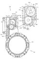
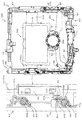
図3に示すように、パチンコ機10の背面側には、制御基板ユニット90,91と、裏パックユニット94とが主に備えられている。制御基板ユニット90は、主基板(主制御装置110)と音声ランプ制御基板(音声ランプ制御装置113)と表示制御基板(表示制御装置114)とが搭載されてユニット化されている。制御基板ユニット91は、払出制御基板(払出制御装置111)と発射制御基板(発射制御装置112)と電源基板(電源装置115)とカードユニット接続基板116とが搭載されてユニット化されている。
As shown in FIG. 3, control board units 90 and 91 and a back pack unit 94 are mainly provided on the back side of the pachinko machine 10. The control board unit 90 is unitized by mounting a main board (main control device 110), a voice lamp control board (voice lamp control device 113), and a display control board (display control device 114). The control board unit 91 is unitized by mounting a payout control board (payout control device 111), a firing control board (firing control device 112), a power supply board (power supply device 115), and a card unit connection board 116.
裏パックユニット94は、保護カバー部を形成する裏パック92と払出ユニット93とがユニット化されている。また、各制御基板には、各制御を司る1チップマイコンとしてのMPU、各種機器との連絡をとるポート、各種抽選の際に用いられる乱数発生器、時間計数や同期を図る場合などに使用されるクロックパルス発生回路等が、必要に応じて搭載されている。
The back pack unit 94 includes a back pack 92 forming a protective cover and a payout unit 93. Also, each control board is used for MPU as a one-chip microcomputer that controls each control, a port for communicating with various devices, a random number generator used in various lottery, time counting and synchronization. A clock pulse generating circuit and the like are installed as needed.
なお、主制御装置110、音声ランプ制御装置113及び表示制御装置114、払出制御装置111及び発射制御装置112、電源装置115、カードユニット接続基板116は、それぞれ基板ボックス100〜104に収納されている。基板ボックス100〜104は、ボックスベースと該ボックスベースの開口部を覆うボックスカバーとを備えており、そのボックスベースとボックスカバーとが互いに連結されて、各制御装置や各基板が収納される。
The main control device 110, the audio lamp control device 113 and the display control device 114, the payout control device 111 and the firing control device 112, the power supply device 115, and the card unit connection board 116 are housed in the board boxes 100 to 104, respectively. . The board boxes 100 to 104 each include a box base and a box cover that covers an opening of the box base. The box base and the box cover are connected to each other to house each control device and each board.
また、基板ボックス100(主制御装置110)及び基板ボックス102(払出制御装置111及び発射制御装置112)は、ボックスベースとボックスカバーとを封印ユニット(図示せず)によって開封不能に連結(かしめ構造による連結)している。また、ボックスベースとボックスカバーとの連結部には、ボックスベースとボックスカバーとに亘って封印シール(図示せず)が貼着されている。この封印シールは、脆性な素材で構成されており、基板ボックス100,102を開封するために封印シールを剥がそうとしたり、基板ボックス100,102を無理に開封しようとすると、ボックスベース側とボックスカバー側とに切断される。よって、封印ユニット又は封印シールを確認することで、基板ボックス100,102が開封されたかどうかを知ることができる。
Further, in the board box 100 (main controller 110) and the board box 102 (payout controller 111 and launch controller 112), a box base and a box cover are connected in an unopenable manner by a sealing unit (not shown) (caulking structure). (Consolidated by). In addition, a seal (not shown) is attached to the connecting portion between the box base and the box cover, extending over the box base and the box cover. The seal sticker is made of a brittle material. If the seal sticker is peeled off to open the board boxes 100 and 102, or if the board boxes 100 and 102 are forcibly opened, the box base side and the box cover are closed. To be cut to the side. Therefore, by checking the sealing unit or the sealing seal, it is possible to know whether the substrate boxes 100 and 102 have been opened.
払出ユニット93は、裏パックユニット94の最上部に位置して上方に開口したタンク130と、タンク130の下方に連結され下流側に向けて緩やかに傾斜するタンクレール131と、タンクレール131の下流側に縦向きに連結されるケースレール132と、ケースレール132の最下流部に設けられ、払出モータ216(図4参照)の所定の電気的構成により球の払出を行う払出装置133とを備えている。タンク130には、遊技ホールの島設備から供給される球が逐次補給され、払出装置133により必要個数の球の払い出しが適宜行われる。タンクレール131には、当該タンクレール131に振動を付加するためのバイブレータ134が取り付けられている。
The payout unit 93 is located at the uppermost part of the back pack unit 94 and opens upward, the tank rail 131 that is connected to the lower side of the tank 130 and gently inclines toward the downstream side, and the downstream of the tank rail 131. A case rail 132 that is vertically connected to the side, and a payout device 133 that is provided at the most downstream portion of the case rail 132 and that pays out balls by a predetermined electrical configuration of the payout motor 216 (see FIG. 4). ing. The tank 130 is sequentially replenished with the balls supplied from the island facility of the game hall, and the required number of balls are appropriately dispensed by the dispensing device 133. A vibrator 134 for applying vibration to the tank rail 131 is attached to the tank rail 131.
また、払出制御装置111には状態復帰スイッチ120が設けられ、発射制御装置112には可変抵抗器の操作つまみ121が設けられ、電源装置115にはRAM消去スイッチ122が設けられている。状態復帰スイッチ120は、例えば、払出モータ216(図4参照)部の球詰まり等、払出エラーの発生時に球詰まりを解消(正常状態への復帰)するために操作される。操作つまみ121は、発射ソレノイドの発射力を調整するために操作される。RAM消去スイッチ122は、パチンコ機10を初期状態に戻したい場合に電源投入時に操作される。
The payout control device 111 is provided with a state return switch 120, the firing control device 112 is provided with a variable resistor operation knob 121, and the power supply device 115 is provided with a RAM erase switch 122. The state return switch 120 is operated to eliminate the ball clogging (return to the normal state) when a dispensing error occurs, such as the ball clogging of the dispensing motor 216 (see FIG. 4). The operation knob 121 is operated to adjust the firing force of the firing solenoid. The RAM erase switch 122 is operated when the power is turned on when it is desired to return the pachinko machine 10 to the initial state.
次に、図4を参照して、本パチンコ機10の電気的構成について説明する。図4は、パチンコ機10の電気的構成を示すブロック図である。
Next, the electrical configuration of the pachinko machine 10 will be described with reference to FIG. FIG. 4 is a block diagram showing an electrical configuration of the pachinko machine 10.
主制御装置110には、演算装置である1チップマイコンとしてのMPU201が搭載されている。MPU201には、該MPU201により実行される各種の制御プログラムや固定値データを記憶したROM202と、そのROM202内に記憶される制御プログラムの実行に際して各種のデータ等を一時的に記憶するためのメモリであるRAM203と、そのほか、割込回路やタイマ回路、データ送受信回路などの各種回路が内蔵されている。主制御装置110では、MPU201によって、大当たり抽選や第1図柄表示装置37A,37B及び第3図柄表示装置81における表示の設定、第2図柄表示装置における表示結果の抽選といったパチンコ機10の主要な処理を実行する。
The main control unit 110 is equipped with an MPU 201 as a one-chip microcomputer which is an arithmetic unit. The MPU 201 includes a ROM 202 that stores various control programs executed by the MPU 201 and fixed value data, and a memory that temporarily stores various data when the control program stored in the ROM 202 is executed. In addition to a certain RAM 203, various circuits such as an interrupt circuit, a timer circuit, and a data transmission / reception circuit are built in. In the main controller 110, the main processing of the pachinko machine 10 such as jackpot lottery, setting of display on the first symbol display devices 37A, 37B and the third symbol display device 81, and lottery of the display result on the second symbol display device by the MPU 201. To execute.
なお、払出制御装置111や音声ランプ制御装置113などのサブ制御装置に対して動作を指示するために、主制御装置110から該サブ制御装置へ各種のコマンドがデータ送受信回路によって送信されるが、かかるコマンドは、主制御装置110からサブ制御装置へ一方向にのみ送信される。
Note that various commands are transmitted from the main control device 110 to the sub control device by the data transmission / reception circuit in order to instruct the sub control devices such as the payout control device 111 and the voice lamp control device 113 to operate. Such a command is transmitted from the main control device 110 to the sub control device in only one direction.
RAM203は、各種エリア、カウンタ、フラグのほか、MPU201の内部レジスタの内容やMPU201により実行される制御プログラムの戻り先番地などが記憶されるスタックエリアと、各種のフラグおよびカウンタ、I/O等の値が記憶される作業エリア(作業領域)とを有している。なお、RAM203は、パチンコ機10の電源の遮断後においても電源装置115からバックアップ電圧が供給されてデータを保持(バックアップ)できる構成となっており、RAM203に記憶されるデータは、すべてバックアップされる。
The RAM 203 stores various areas, counters, flags, a stack area for storing the contents of internal registers of the MPU 201, the return address of the control program executed by the MPU 201, various flags, counters, I / O, etc. And a work area (work area) in which values are stored. The RAM 203 is configured to be able to retain (backup) data by being supplied with a backup voltage from the power supply device 115 even after the power of the pachinko machine 10 is cut off, and all the data stored in the RAM 203 is backed up. .
停電などの発生により電源が遮断されると、その電源遮断時(停電発生時を含む。以下同様)のスタックポインタや、各レジスタの値がRAM203に記憶される。一方、電源投入時(停電解消による電源投入を含む。以下同様)には、RAM203に記憶される情報に基づいて、パチンコ機10の状態が電源遮断前の状態に復帰される。RAM203への書き込みはメイン処理(図示せず)によって電源遮断時に実行され、RAM203に書き込まれた各値の復帰は電源投入時の立ち上げ処理(図示せず)において実行される。なお、MPU201のNMI端子(ノンマスカブル割込端子)には、停電等の発生による電源遮断時に、停電監視回路252からの停電信号SG1が入力されるように構成されており、その停電信号SG1がMPU201へ入力されると、停電時処理としてのNMI割込処理(図示せず)が即座に実行される。
When the power is cut off due to the occurrence of a power failure or the like, the RAM 203 stores the stack pointer at the time of the power shutdown (including the occurrence of a power failure. The same applies to the following) and the value of each register. On the other hand, when the power is turned on (including turning on the power by eliminating the power failure. The same applies to the following), the state of the pachinko machine 10 is restored to the state before the power was turned off based on the information stored in the RAM 203. Writing to the RAM 203 is executed by a main process (not shown) when the power is cut off, and restoration of each value written in the RAM 203 is executed by a startup process (not shown) when the power is turned on. The NMI terminal (non-maskable interrupt terminal) of the MPU 201 is configured so that the power failure signal SG1 from the power failure monitoring circuit 252 is input when the power is shut down due to a power failure or the like, and the power failure signal SG1 is input to the MPU 201. When input to, the NMI interrupt processing (not shown) as the power failure processing is immediately executed.
主制御装置110のMPU201には、アドレスバス及びデータバスで構成されるバスライン204を介して入出力ポート205が接続されている。入出力ポート205には、払出制御装置111、音声ランプ制御装置113、第1図柄表示装置37A,37B、第2図柄表示装置、第2図柄保留ランプ、特定入賞口65aの開閉板の下辺を軸として前方側に開閉駆動するための大開放口ソレノイドや電動役物を駆動するためのソレノイドなどからなるソレノイド209が接続され、MPU201は、入出力ポート205を介してこれらに対し各種コマンドや制御信号を送信する。
An input / output port 205 is connected to the MPU 201 of the main controller 110 via a bus line 204 composed of an address bus and a data bus. In the input / output port 205, the payout control device 111, the voice lamp control device 113, the first symbol display devices 37A and 37B, the second symbol display device, the second symbol holding lamp, the lower side of the opening / closing plate of the specific winning opening 65a is an axis. Is connected to a solenoid 209 including a large opening solenoid for opening / closing driving forward and a solenoid for driving an electric accessory, and the MPU 201 sends various command and control signals to them via an input / output port 205. To send.
また、入出力ポート205には、図示しないスイッチ群およびスライド位置検出センサSや回転位置検出センサRを含むセンサ群などからなる各種スイッチ208、電源装置115に設けられた後述のRAM消去スイッチ回路253が接続され、MPU201は各種スイッチ208から出力される信号や、RAM消去スイッチ回路253より出力されるRAM消去信号SG2に基づいて各種処理を実行する。
In addition, the input / output port 205 includes various switches 208 including a switch group (not shown) and a sensor group including the slide position detection sensor S and the rotational position detection sensor R, and a RAM erase switch circuit 253 (described later) provided in the power supply device 115. Are connected, and the MPU 201 executes various processes based on the signals output from the various switches 208 and the RAM erase signal SG2 output from the RAM erase switch circuit 253.
払出制御装置111は、払出モータ216を駆動させて賞球や貸出球の払出制御を行うものである。演算装置であるMPU211は、そのMPU211により実行される制御プログラムや固定値データ等を記憶したROM212と、ワークメモリ等として使用されるRAM213とを有している。
The payout control device 111 drives the payout motor 216 to perform payout control of prize balls and rental balls. The MPU 211, which is a computing device, has a ROM 212 that stores a control program executed by the MPU 211, fixed value data, and the like, and a RAM 213 that is used as a work memory and the like.
払出制御装置111のRAM213は、主制御装置110のRAM203と同様に、MPU211の内部レジスタの内容やMPU211により実行される制御プログラムの戻り先番地などが記憶されるスタックエリアと、各種のフラグおよびカウンタ、I/O等の値が記憶される作業エリア(作業領域)とを有している。RAM213は、パチンコ機10の電源の遮断後においても電源装置115からバックアップ電圧が供給されてデータを保持(バックアップ)できる構成となっており、RAM213に記憶されるデータは、すべてバックアップされる。なお、主制御装置110のMPU201と同様、MPU211のNMI端子にも、停電等の発生による電源遮断時に停電監視回路252から停電信号SG1が入力されるように構成されており、その停電信号SG1がMPU211へ入力されると、停電時処理としてのNMI割込処理(図示せず)が即座に実行される。
The RAM 213 of the payout control device 111, like the RAM 203 of the main control device 110, has a stack area in which the contents of the internal registers of the MPU 211 and the return address of the control program executed by the MPU 211 are stored, and various flags and counters. , I / O and the like are stored in the work area (work area). The RAM 213 has a configuration in which a backup voltage is supplied from the power supply device 115 and data can be retained (backup) even after the power of the pachinko machine 10 is cut off, and all the data stored in the RAM 213 is backed up. Note that, like the MPU 201 of the main control device 110, the NMI terminal of the MPU 211 is also configured to receive the power failure signal SG1 from the power failure monitoring circuit 252 when the power is shut off due to the occurrence of a power failure or the like, and the power failure signal SG1 is input. When input to the MPU 211, an NMI interrupt process (not shown) as a power failure process is immediately executed.
払出制御装置111のMPU211には、アドレスバス及びデータバスで構成されるバスライン214を介して入出力ポート215が接続されている。入出力ポート215には、主制御装置110や払出モータ216、発射制御装置112などがそれぞれ接続されている。また、図示はしないが、払出制御装置111には、払い出された賞球を検出するための賞球検出スイッチが接続されている。なお、該賞球検出スイッチは、払出制御装置111に接続されるが、主制御装置110には接続されていない。
An input / output port 215 is connected to the MPU 211 of the payout control device 111 via a bus line 214 composed of an address bus and a data bus. The main controller 110, the payout motor 216, the firing controller 112, etc. are connected to the input / output port 215, respectively. Although not shown, the payout control device 111 is connected to a prize ball detection switch for detecting the paid prize balls. The prize ball detection switch is connected to the payout control device 111 but not to the main control device 110.
発射制御装置112は、主制御装置110により球の発射の指示がなされた場合に、操作ハンドル51の回動操作量に応じた球の打ち出し強さとなるよう球発射ユニット112aを制御するものである。球発射ユニット112aは、図示しない発射ソレノイドおよび電磁石を備えており、その発射ソレノイドおよび電磁石は、所定条件が整っている場合に駆動が許可される。具体的には、遊技者が操作ハンドル51に触れていることをタッチセンサ51aにより検出し、球の発射を停止させるための発射停止スイッチ51bがオフ(操作されていないこと)を条件に、操作ハンドル51の回動操作量(回動位置)に対応して発射ソレノイドが励磁され、操作ハンドル51の操作量に応じた強さで球が発射される。
The firing control device 112 controls the ball firing unit 112a so that when the main control device 110 issues an instruction to fire a sphere, the sphere launching unit 112a has a launching strength corresponding to the turning operation amount of the operation handle 51. . The ball firing unit 112a includes a firing solenoid and an electromagnet, which are not shown, and the firing solenoid and the electromagnet are permitted to be driven when a predetermined condition is satisfied. Specifically, the touch sensor 51a detects that the player is touching the operation handle 51, and the firing stop switch 51b for stopping the firing of the ball is turned off (not operated). The firing solenoid is excited according to the amount of rotation operation (rotational position) of the handle 51, and a ball is emitted with a strength corresponding to the amount of operation of the operation handle 51.
音声ランプ制御装置113は、音声出力装置(図示しないスピーカなど)226における音声の出力、ランプ表示装置(電飾部29〜33、表示ランプ34など)227における点灯および消灯の出力、変動演出(変動表示)や予告演出といった表示制御装置114で行われる第3図柄表示装置81の表示態様の設定などを制御するものである。演算装置であるMPU221は、そのMPU221により実行される制御プログラムや固定値データ等を記憶したROM222と、ワークメモリ等として使用されるRAM223とを有している。
The voice lamp control device 113 outputs a voice in a voice output device (such as a speaker (not shown)) 226, outputs a light and a light in a lamp display device (such as the illumination units 29 to 33 and the display lamp 34) 227, and produces a variation (variation). It is for controlling the setting of the display mode of the third symbol display device 81 performed by the display control device 114 such as display) and notice production. The MPU 221 as an arithmetic unit has a ROM 222 that stores a control program executed by the MPU 221 and fixed value data, and a RAM 223 used as a work memory.
音声ランプ制御装置113のMPU221には、アドレスバス及びデータバスで構成されるバスライン224を介して入出力ポート225が接続されている。入出力ポート225には、主制御装置110、表示制御装置114、音声出力装置226、ランプ表示装置227、その他装置228、枠ボタン22などがそれぞれ接続されている。
An input / output port 225 is connected to the MPU 221 of the audio lamp control device 113 via a bus line 224 composed of an address bus and a data bus. The main control device 110, the display control device 114, the audio output device 226, the lamp display device 227, the other device 228, the frame button 22, and the like are connected to the input / output port 225.
音声ランプ制御装置113は、主制御装置110から受信した各種のコマンド(変動パターンコマンド、停止種別コマンド等)に基づいて、第3図柄表示装置81の表示態様を決定し、決定した表示態様をコマンド(表示用変動パターンコマンド、表示用停止種別コマンド等)によって表示制御装置114へ通知する。また、音声ランプ制御装置113は、枠ボタン22からの入力を監視し、遊技者によって枠ボタン22が操作された場合は、第3図柄表示装置81で表示されるステージを変更したり、スーパーリーチ時の演出内容を変更したりするように、表示制御装置114へ指示する。ステージが変更される場合は、変更後のステージに応じた背面画像を第3図柄表示装置81に表示させるべく、変更後のステージに関する情報を含めた背面画像変更コマンドを表示制御装置114へ送信する。ここで、背面画像とは、第3図柄表示装置81に表示させる主要な画像である第3図柄の背面側に表示される画像のことである。表示制御装置114は、この音声ランプ制御装置113から送信されるコマンドに従って、第3図柄表示装置81に各種の画像を表示する。
The voice lamp control device 113 determines the display mode of the third symbol display device 81 based on various commands (variation pattern command, stop type command, etc.) received from the main control device 110, and commands the determined display mode. The display control device 114 is notified by (display variation pattern command, display stop type command, etc.). Further, the voice lamp control device 113 monitors the input from the frame button 22, and when the frame button 22 is operated by the player, the stage displayed on the third symbol display device 81 is changed or the super reach is performed. The display control device 114 is instructed to change the contents of the effect at that time. When the stage is changed, a rear image change command including information about the changed stage is transmitted to the display control device 114 in order to display the rear image according to the changed stage on the third symbol display device 81. . Here, the back image is an image displayed on the back side of the third symbol which is the main image displayed on the third symbol display device 81. The display control device 114 displays various images on the third symbol display device 81 in accordance with the command transmitted from the voice lamp control device 113.
また、音声ランプ制御装置113は、表示制御装置114から第3図柄表示装置81の表示内容を表すコマンド(表示コマンド)を受信する。音声ランプ制御装置113では、表示制御装置114から受信した表示コマンドに基づき、第3図柄表示装置81の表示内容に合わせて、その表示内容に対応する音声を音声出力装置226から出力し、また、その表示内容に対応させてランプ表示装置227の点灯および消灯を制御する。
Further, the voice lamp control device 113 receives a command (display command) indicating the display content of the third symbol display device 81 from the display control device 114. In the voice lamp control device 113, based on the display command received from the display control device 114, in accordance with the display content of the third symbol display device 81, a voice corresponding to the display content is output from the voice output device 226, and, Lighting and extinguishing of the lamp display device 227 are controlled in accordance with the displayed contents.
表示制御装置114は、音声ランプ制御装置113及び第3図柄表示装置81が接続され、音声ランプ制御装置113より受信したコマンドに基づいて、第3図柄表示装置81における第3図柄の変動演出などの表示を制御するものである。また、表示制御装置114は、第3図柄表示装置81の表示内容を通知する表示コマンドを適宜音声ランプ制御装置113へ送信する。音声ランプ制御装置113は、この表示コマンドによって示される表示内容にあわせて音声出力装置226から音声を出力することで、第3図柄表示装置81の表示と音声出力装置226からの音声出力とをあわせることができる。
The display control device 114 is connected to the voice lamp control device 113 and the third symbol display device 81, and based on a command received from the voice lamp control device 113, such as a variation effect of the third symbol in the third symbol display device 81. It controls the display. Further, the display control device 114 appropriately transmits a display command for notifying the display content of the third symbol display device 81 to the voice lamp control device 113. The voice lamp control device 113 outputs the voice from the voice output device 226 in accordance with the display content indicated by this display command, thereby matching the display of the third symbol display device 81 and the voice output from the voice output device 226. be able to.
電源装置115は、パチンコ機10の各部に電源を供給するための電源部251と、停電等による電源遮断を監視する停電監視回路252と、RAM消去スイッチ122(図3参照)が設けられたRAM消去スイッチ回路253とを有している。電源部251は、図示しない電源経路を通じて、各制御装置110〜114等に対して各々に必要な動作電圧を供給する装置である。その概要としては、電源部251は、外部より供給される交流24ボルトの電圧を取り込み、各種スイッチ208などの各種スイッチや、ソレノイド209などのソレノイド、モータ等を駆動するための12ボルトの電圧、ロジック用の5ボルトの電圧、RAMバックアップ用のバックアップ電圧などを生成し、これら12ボルトの電圧、5ボルトの電圧及びバックアップ電圧を各制御装置110〜114等に対して必要な電圧を供給する。
The power supply device 115 is provided with a power supply unit 251 for supplying power to each unit of the pachinko machine 10, a power failure monitoring circuit 252 for monitoring power interruption due to power failure, etc., and a RAM erase switch 122 (see FIG. 3). And an erase switch circuit 253. The power supply unit 251 is a device that supplies a necessary operating voltage to each of the control devices 110 to 114 and the like through a power supply path (not shown). As its outline, the power supply unit 251 takes in a voltage of 24 V AC supplied from the outside, and 12 V voltage for driving various switches such as the various switches 208, solenoids such as the solenoid 209, and motors, A voltage of 5 V for logic, a backup voltage for RAM backup, and the like are generated, and the voltages of 12 V, 5 V, and backup voltage are supplied to the control devices 110 to 114 and the like as necessary.
停電監視回路252は、停電等の発生による電源遮断時に、主制御装置110のMPU201及び払出制御装置111のMPU211の各NMI端子へ停電信号SG1を出力するための回路である。停電監視回路252は、電源部251から出力される最大電圧である直流安定24ボルトの電圧を監視し、この電圧が22ボルト未満になった場合に停電(電源断、電源遮断)の発生と判断して、停電信号SG1を主制御装置110及び払出制御装置111へ出力する。停電信号SG1の出力によって、主制御装置110及び払出制御装置111は、停電の発生を認識し、NMI割込処理を実行する。なお、電源部251は、直流安定24ボルトの電圧が22ボルト未満になった後においても、NMI割込処理の実行に充分な時間の間、制御系の駆動電圧である5ボルトの電圧の出力を正常値に維持するように構成されている。よって、主制御装置110及び払出制御装置111は、NMI割込処理(図示せず)を正常に実行し完了することができる。
The power outage monitoring circuit 252 is a circuit for outputting a power outage signal SG1 to each NMI terminal of the MPU 201 of the main control device 110 and the MPU 211 of the payout control device 111 when the power is shut off due to the occurrence of a power outage or the like. The power failure monitoring circuit 252 monitors the voltage of DC stable 24V which is the maximum voltage output from the power supply unit 251, and determines that a power failure (power cut, power cut) occurs when this voltage becomes less than 22V. Then, the power failure signal SG1 is output to the main controller 110 and the payout controller 111. By the output of the power failure signal SG1, the main control device 110 and the payout control device 111 recognize the occurrence of the power failure and execute the NMI interrupt process. Note that the power supply unit 251 outputs the voltage of 5 V which is the drive voltage of the control system for a time sufficient to execute the NMI interrupt processing even after the voltage of DC stable 24 V becomes less than 22 V. Is maintained at a normal value. Therefore, the main controller 110 and the payout controller 111 can normally execute and complete the NMI interrupt process (not shown).
RAM消去スイッチ回路253は、RAM消去スイッチ122(図3参照)が押下された場合に、主制御装置110へ、バックアップデータをクリアさせるためのRAM消去信号SG2を出力するための回路である。主制御装置110は、パチンコ機10の電源投入時に、RAM消去信号SG2を入力した場合に、バックアップデータをクリアすると共に、払出制御装置111においてバックアップデータをクリアさせるための払出初期化コマンドを払出制御装置111に対して送信する。
The RAM erase switch circuit 253 is a circuit for outputting a RAM erase signal SG2 for clearing backup data to the main controller 110 when the RAM erase switch 122 (see FIG. 3) is pressed. When the RAM erase signal SG2 is input when the pachinko machine 10 is powered on, the main controller 110 clears the backup data, and the payout controller 111 issues a payout initialization command for clearing the backup data. It transmits to the device 111.
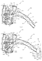
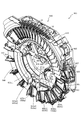
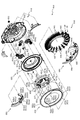
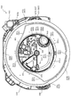
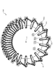
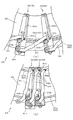
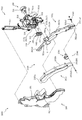
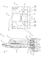
次いで、図5から図10を参照して、動作ユニット200の概略構成について説明する。図5は、動作ユニット200の分解正面斜視図であり、図6は、遊技盤13及び動作ユニット200の正面斜視図である。また、図7は、動作ユニット200の正面斜視図であり、図8から図10は、動作ユニット200の正面図である。
Next, a schematic configuration of the operation unit 200 will be described with reference to FIGS. 5 to 10. FIG. 5 is an exploded front perspective view of the operation unit 200, and FIG. 6 is a front perspective view of the game board 13 and the operation unit 200. Further, FIG. 7 is a front perspective view of the operation unit 200, and FIGS. 8 to 10 are front views of the operation unit 200.
なお、図6及び図7では、液晶昇降ユニット400が下降位置に配置された状態が、図9では、液晶昇降ユニット400の第2通路形成部材422と左揺動ユニット500の第1通路形成部材520とが連結された状態が、図10では、液晶昇降ユニット600が上昇位置に配置された状態が、それぞれ図示される。また、図6から図10では、上部昇降ユニット300が上昇位置に配置された状態が図示される。
6 and 7, the state in which the liquid crystal elevating unit 400 is arranged at the lowered position is shown in FIG. 9, but in FIG. 9, the second passage forming member 422 of the liquid crystal elevating unit 400 and the first passage forming member of the left swing unit 500 are shown. FIG. 10 illustrates a state in which the liquid crystal elevating unit 600 is connected to the liquid crystal elevating unit 600, and FIG. Further, FIGS. 6 to 10 show the state in which the upper elevating unit 300 is arranged in the raised position.
図5から図10に示すように、動作ユニット200は、箱状に形成される背面ケース210を備え、その背面ケース210の内部空間に、上部昇降ユニット300、液晶昇降ユニット400、左揺動ユニット500、回転ユニット600及び発光装飾部材700がそれぞれ収容される。
As shown in FIGS. 5 to 10, the operation unit 200 includes a rear case 210 formed in a box shape, and an upper elevating unit 300, a liquid crystal elevating unit 400, and a left swing unit in the inner space of the rear case 210. 500, the rotation unit 600, and the light-emission decoration member 700 are respectively accommodated.
背面ケース210は、正面視略矩形の底壁部211と、その底壁部211の4辺の外縁から正面へ向けて立設される外壁部212とを備え、これら各壁部211,212により一面側が開放された箱状に形成される。背面ケース210の底壁部211には、その中央に正面性略円形の凹部が凹設され、その凹部に回転ユニット600が収納される。液晶昇降ユニット400は、回転ユニット600の正面側に配設され、上部昇降ユニット300、左揺動ユニット500及び装飾発光部材700は、液晶昇降ユニット400の上側縁部、左側縁部および下側縁部にそれぞれ配設される。
The rear case 210 includes a bottom wall portion 211 that is substantially rectangular in a front view, and an outer wall portion 212 that is erected from the outer edges of the four sides of the bottom wall portion 211 toward the front. It is formed in a box shape with one side open. The bottom wall portion 211 of the rear case 210 is provided with a concave portion having a substantially circular frontal shape in the center thereof, and the rotary unit 600 is housed in the concave portion. The liquid crystal elevating unit 400 is disposed on the front side of the rotating unit 600, and the upper elevating unit 300, the left swing unit 500, and the decorative light emitting member 700 include the upper edge, the left edge, and the lower edge of the liquid crystal elevating unit 400. Are arranged in each part.
上部昇降ユニット300は、複数(本実施形態では4個)が幅方向(図8左右方向)に並設される昇降体330を備え、それら昇降体330がそれぞれ独立して高さ方向(図8上下方向)に昇降可能に形成される(図12及び図13参照)。液晶昇降ユニット400が下降位置に配置された状態では、昇降体330が上昇位置に配置されると、第3図柄表示装置81のほぼ全面が視認可能とされる一方(図8参照)、昇降体330が下降位置に配置されると(図12参照)、かかる昇降体330により第3図柄表示装置81の一部が視認不能とされる。
The upper elevating unit 300 includes a plurality of (four in the present embodiment) elevator bodies 330 arranged side by side in the width direction (left-right direction in FIG. 8), and these elevator bodies 330 are independent in the height direction (FIG. 8). It is formed so as to be vertically movable (see FIGS. 12 and 13). In the state where the liquid crystal lifting unit 400 is arranged in the lowered position, when the lifting body 330 is arranged in the raised position, almost the entire surface of the third symbol display device 81 is visible (see FIG. 8), while the lifting body is lifted. When 330 is arranged in the lowered position (see FIG. 12), a part of the third symbol display device 81 is made invisible due to the elevating body 330.
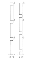
液晶昇降ユニット400は、軸を上下方向に沿わせた縦姿勢で配設されると共に幅方向に所定間隔を隔てて配設される一対の案内棒451と、その案内棒451に幅方向両端がスライド変位可能に支持される駆動側スライド部材420及び従動側スライド部材430と、駆動側スライド部材420を昇降駆動する駆動モータ441とを備え、その駆動モータ441により駆動側スライド部材420が昇降駆動されることで、従動側スライド部材430が従動して昇降される。
The liquid crystal elevating unit 400 is arranged in a vertical posture with its axis extending in the vertical direction, and is provided with a pair of guide bars 451 arranged at predetermined intervals in the width direction. The driving-side slide member 420 and the driven-side slide member 430 are slidably supported, and a drive motor 441 that drives the drive-side slide member 420 up and down. The drive motor 441 drives the drive-side slide member 420 up and down. As a result, the driven-side slide member 430 is driven and moved up and down.
即ち、駆動側スライド部材420が上昇される際には、かかる駆動側スライド部材420が従動側スライド部材430を重力の作用に抗しつつ上方へ押し上げる一方、駆動側スライド部材420が下降される際には、その駆動側スライド部材420の下降に伴い、従動側スライド部材430が自重により下降される。
That is, when the drive-side slide member 420 is raised, the drive-side slide member 420 pushes the driven-side slide member 430 upward while resisting the action of gravity, while the drive-side slide member 420 is lowered. The driven-side slide member 430 is lowered by its own weight as the drive-side slide member 420 is lowered.
なお、駆動側スライド部材420には、第2通路形成部材422が配設され、従動側スライド部材430には、第3図柄表示装置81が配設される。駆動側スライド部材420が、上昇位置および下降位置の間の連結位置に配置されると、第2通路形成部材422が左揺動ユニット500の第1通路形成部材520と連結可能とされる(図9参照)。また、駆動側スライド部材420が、上昇位置に配置されると、第3図柄表示装置81の上方領域が上部昇降ユニット300の背面側に配置される(図10参照)。
The drive-side slide member 420 is provided with the second passage forming member 422, and the driven-side slide member 430 is provided with the third symbol display device 81. When the drive-side slide member 420 is arranged at the connecting position between the ascending position and the descending position, the second passage forming member 422 can be connected to the first passage forming member 520 of the left swing unit 500 (Fig. 9). When the drive-side slide member 420 is arranged in the raised position, the upper region of the third symbol display device 81 is arranged on the back side of the upper elevating unit 300 (see FIG. 10).
左揺動ユニット500は、基端側を中心として先端側を上下させる方向へ揺動される第1通路形成部材520を備える。第1通路形成部材520は、先端側を持ち上げる方向へ揺動されると、連結位置に配置され(図9参照)、先端側が液晶昇降ユニット400の第2通路形成部材422に連結される一方、先端側を振り下げる方向へ揺動されると、解除位置に配置され(図10参照)、液晶昇降ユニット400の第2通路形成部材422との連結が解除される。
The left swing unit 500 includes a first passage forming member 520 which is swung in a direction in which the tip end side is moved up and down around the base end side. When the first passage forming member 520 is swung in the direction of lifting the front end side, the first passage forming member 520 is disposed at the connecting position (see FIG. 9), and the front end side is connected to the second passage forming member 422 of the liquid crystal elevating unit 400. When the tip end side is swung in the swing-down direction, it is placed at the release position (see FIG. 10) and the connection with the second passage forming member 422 of the liquid crystal elevating unit 400 is released.
遊技領域を流下する球は、左揺動ユニット500内へ流入可能とされ、左揺動ユニット500は、第1通路形成部材520が連結位置に配置された状態では(図9参照)、流入された球を、第1通路形成部材520を介して、液晶昇降ユニット400の第2通路形成部材422へ送球する一方、第1通路形成部材520が解除位置に配置された状態では(図10参照)、流入された球を、第1通路形成部材520とは別に設けられた後述する通路を介して、遊技領域へ送球する。
The ball flowing down the game area is allowed to flow into the left swing unit 500, and the left swing unit 500 is flowed in when the first passage forming member 520 is arranged at the connecting position (see FIG. 9). The ball is sent to the second passage forming member 422 of the liquid crystal lifting unit 400 via the first passage forming member 520, while the first passage forming member 520 is in the release position (see FIG. 10). The inflowing sphere is delivered to the game area through a passage, which will be described later, provided separately from the first passage forming member 520.
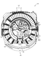
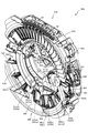
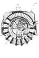
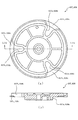
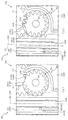
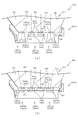
回転ユニット600は、ルーレットを模して構成される演出装置である。即ち、回転可能に形成されるホイール(回転盤)に相当する部材(回転部材640)と、そのホイールを周方向に区画して形成され赤または黒の色が付されると共にそれぞれ異なる数字が表示されるポケットに相当する部分(表示板646及び区画板647)とを備え、ホイールの内周側の装置(投球装置650)から投球された球Bが、複数のポケットに相当する部分のうちのいずれかに落下するように形成される。
The rotating unit 600 is a rendering device configured to imitate a roulette wheel. That is, a member (rotating member 640) corresponding to a rotatably formed wheel (rotating plate), and a red or black color formed by partitioning the wheel in the circumferential direction and different numbers are displayed. A portion corresponding to a plurality of pockets (a display plate 646 and a partition plate 647) and a ball B thrown from a device on the inner peripheral side of the wheel (pitching device 650) corresponds to a plurality of pockets. It is formed to fall on either.
液晶昇降ユニット400が下降位置に配置された状態では(図8参照)、回転ユニット600のほぼ全体が液晶昇降ユニット400によって遊技者から視認不能に遮蔽される一方、液晶昇降ユニット400が連結位置に配置された状態では(図9参照)、ホイールに相当する部材の一部(下方部分)が露出されると共に、液晶昇降ユニット400が上昇位置に配置された状態では(図10参照)、ホイールに相当する部材の一部(下方部分)に加え、ホイールに相当する部材の内周側に保持されている球B及びその球Bが投球されてからポケットに相当する部分に落下するまでの経路が露出され、これらが遊技者から視認可能とされる。
In a state where the liquid crystal lifting unit 400 is arranged in the lowered position (see FIG. 8), almost the entire rotation unit 600 is shielded by the liquid crystal lifting unit 400 so as not to be visually recognized by the player, while the liquid crystal lifting unit 400 is placed in the connecting position. In the arranged state (see FIG. 9), a part (lower part) of the member corresponding to the wheel is exposed, and in the state where the liquid crystal elevating unit 400 is arranged in the raised position (see FIG. 10), the wheel is In addition to a part (lower part) of the corresponding member, the ball B held on the inner peripheral side of the member corresponding to the wheel and the path from the throwing of the ball B to the drop to the part corresponding to the pocket are It is exposed and these are visible to the player.
発光装飾部材700は、光透過性の材料から形成されるケース体と、そのケース体の内部に配設される複数のLEDとを備え、LEDから発光する光の態様(例えば、発光するLEDの数や発光時間)を変更することで、発光による演出を行う。
The light-emitting decoration member 700 includes a case body formed of a light-transmissive material and a plurality of LEDs arranged inside the case body, and the aspect of the light emitted from the LED (for example, of a light-emitting LED). By changing the number and the light emission time), the effect by light emission is performed.
また、遊技盤13のセンターフレーム86には、中央に開口される開口部の右側内縁に、光を照射する基板部材とその基板部材850から照射される光を内部に入射して発光する導光部材810,820とを備えた発光ユニット800が配設される。
Further, in the center frame 86 of the game board 13, a light guide member that irradiates light to the inside of the center member 86 of the opening that is opened in the center and light emitted from the substrate member 850 is emitted inside. A light emitting unit 800 including members 810 and 820 is arranged.
図11は、上部昇降ユニット300の正面斜視図であり、図12及び図13は、上部昇降ユニット300の正面図である。なお、図11及び図12では、幅方向(図12左右方向)に並設される全ての昇降体330が上昇位置に配置された状態が図示され、図13では、全ての昇降体330が下降位置に配置された状態が図示される。
FIG. 11 is a front perspective view of the upper lifting unit 300, and FIGS. 12 and 13 are front views of the upper lifting unit 300. 11 and 12 show a state in which all the elevating bodies 330 arranged side by side in the width direction (horizontal direction in FIG. 12) are arranged at the ascending position. In FIG. 13, all the elevating bodies 330 are lowered. The state where it is arranged at the position is illustrated.
図11から図13に示すように、上部昇降ユニット300は、横長矩形板形状のベース部材310の幅方向に昇降体330が複数(本実施形態では4個)配設され、各昇降体330が上昇位置(図12参照)と下降位置(図13参照)との間を昇降移動可能に構成される。次いで、図14及び図15を参照して、各昇降体330の駆動機構の構成について説明する。
As shown in FIG. 11 to FIG. 13, in the upper elevating unit 300, a plurality of elevating bodies 330 (four in this embodiment) are arranged in the width direction of the base member 310 having a horizontally long rectangular plate shape. It is configured to be movable up and down between a raised position (see FIG. 12) and a lowered position (see FIG. 13). Next, with reference to FIG. 14 and FIG. 15, the configuration of the drive mechanism of each elevating body 330 will be described.
図14は、上部昇降ユニット300の正面分解斜視図であり、図15は、上部昇降ユニット300の背面分解斜視図である。
FIG. 14 is a front exploded perspective view of the upper lifting unit 300, and FIG. 15 is a rear exploded perspective view of the upper lifting unit 300.
図14及び図15に図示されるように、上部昇降ユニット300は、横長矩形板形状のベース部材310と、そのベース部材310との間に伝達装置350を収容する空間を設けながらベース部材310の背面側に締結固定される背面カバー320と、ベース部材310及び背面カバー320の間にラック332が収容されると共に円形の演出部331がベース部材310の正面側に配置される昇降体330と、背面カバー320に締結固定され昇降体の昇降動作に必要な駆動力を発生させる駆動装置340と、その駆動装置340が発生する駆動力を昇降体330に伝達させる伝達装置350と、を主に備える。
As shown in FIGS. 14 and 15, the upper elevating unit 300 includes a base member 310 having a horizontally long rectangular plate shape, and a space for accommodating the transmission device 350 is provided between the base member 310 and the base member 310. A back cover 320 that is fastened and fixed to the back side; an elevating body 330 in which a rack 332 is housed between the base member 310 and the back cover 320, and a circular effect part 331 is arranged on the front side of the base member 310; A driving device 340 that is fastened and fixed to the back cover 320 to generate a driving force necessary for the lifting / lowering operation of the lifting body, and a transmission device 350 that transfers the driving force generated by the driving device 340 to the lifting / lowering body 330 are mainly provided. .
ベース部材310は、下端に円の中心が配置される半円形状で正面側側面から背面側へ向けて凹設される半円凹設部311と、背面側側面から昇降体330のラック332の左右方向に若干隙間を空けた位置へ向かってリブ状に凸設される案内リブ部312と、を備える。
The base member 310 has a semicircular concave portion 311 having a semicircular shape in which a center of a circle is arranged at a lower end and concaved from a front side surface to a rear surface side, and a rack 332 of the lift 330 from the rear side surface. The guide rib portion 312 is provided so as to project in a rib shape toward a position with a slight gap left and right.
半円凹設部311は、昇降体330の演出部331の外径よりも若干大きな半径で構成され、その半円凹設部311の円の中心と、演出部331の中心とが鉛直線状で一致する位置に配置される。これにより、演出部331が上昇移動する際に、ベース部材310の正面側において半円凹設部311と干渉する位置の手前まで移動することが可能となり、ベース部材310の上下幅は確保しつつ、演出部331の上昇移動幅も大きく確保することができる。
The semicircular recessed portion 311 has a radius slightly larger than the outer diameter of the rendering portion 331 of the lifting body 330, and the center of the circle of the semicircular recessed portion 311 and the center of the rendering portion 331 are vertical lines. Are placed at the same position. Thereby, when the effect part 331 moves upward, it is possible to move to a position before the position where it interferes with the semi-circular recessed part 311 on the front side of the base member 310, while ensuring the vertical width of the base member 310. It is also possible to secure a large upward movement width of the rendering unit 331.
案内リブ部312は、鉛直方向に延びるリブ状の部分であって、組立状態(図11参照)において、昇降体330のラック332の左右側面と当接可能な位置まで凸設される。これにより、昇降体330が昇降移動中に左右方向に移動する(並行移動や傾斜動作する)ことを抑制することができる。
The guide rib portion 312 is a rib-shaped portion that extends in the vertical direction, and is provided so as to project to a position where it can contact the left and right side surfaces of the rack 332 of the elevating body 330 in the assembled state (see FIG. 11). This can prevent the elevating body 330 from moving in the left-right direction during vertical movement (parallel movement or tilting operation).
また、半円凹設部311を正面側から背面側へ凹設される凹部として構成することで、前後方向に貫通する空間とする場合に比較して、背面側を視認不能とできる面積を広げることができる。従って、機構部分(ギアやモータ等の、遊技者に視認させることを目的としない部分)を配設する面積を大きく確保できる。
Further, by forming the semicircular recessed portion 311 as a recessed portion that is recessed from the front side to the back side, the area where the back side cannot be visually recognized is increased as compared with the case where the space penetrates in the front-back direction. be able to. Therefore, it is possible to secure a large area for arranging the mechanical portion (a portion not intended to be visually recognized by the player, such as a gear or a motor).
背面カバー320は、正面側および下方が開放されたケース状に構成される本体部321と、その本体部321から正面側に凸設される円柱形状の軸支部322と、その軸支部322から正面視左右方向に位置ずれした位置において延設方向を鉛直方向と一致させた状態で穿設される長孔である案内孔323と、上側の軸支部322が凸設される周囲の底部から軸支部322の径方向に沿設されるリブ状に形成される係止部324と、を備える。
The back cover 320 includes a main body 321 formed in a case shape with the front side and the lower side open, a columnar shaft support 322 protruding from the main body 321 to the front side, and a front support from the shaft support 322. A guide hole 323, which is a long hole formed in a position displaced in the left-right direction as viewed in the state where the extending direction is aligned with the vertical direction, and a shaft support part from a bottom part around which the upper shaft support part 322 is projectingly provided. 322, and a locking portion 324 that is formed in a rib shape and that is provided along the radial direction of 322.
軸支部322は、伝達装置350の一対のギア部材351,352をそれぞれ軸支する部分であり、案内孔323は、昇降体330の昇降動作を案内する孔である。
The shaft support portion 322 is a portion that respectively supports the pair of gear members 351 and 352 of the transmission device 350, and the guide hole 323 is a hole that guides the lifting operation of the lifting body 330.
係止部324は、上側の軸支部322の軸に対して、鉛直方向上側と鉛直方向下側とに配設され、それぞれ昇降体330が上昇位置または下降位置に配置された状態において、第1ギア351の係止円弧部351cの端部が回転方向で当接可能とされる部分である。
The locking portions 324 are arranged on the upper side in the vertical direction and on the lower side in the vertical direction with respect to the shaft of the upper shaft support portion 322, and when the elevating body 330 is arranged in the raised position or the lowered position, respectively, the first The end portion of the locking arc portion 351c of the gear 351 is a portion that can abut in the rotation direction.
昇降体330は、円形板形状に構成される演出部331と、その演出部331の背面に固定され演出部331の背面側側面から隙間を空けた位置において鉛直方向に延設されるラック332と、を備える。
The elevating body 330 includes a rendering unit 331 configured in a circular plate shape, and a rack 332 fixed to the back of the rendering unit 331 and vertically extending at a position spaced from the rear side surface of the rendering unit 331. , Is provided.
演出部331は、円形の外枠の内側に円形の液晶パネルが配設され、液晶パネルに模様や図形を表示することにより演出を行う部分である。
The production section 331 is a section in which a circular liquid crystal panel is arranged inside a circular outer frame, and a production is performed by displaying patterns and figures on the liquid crystal panel.
ラック332は、背面側に凸設されると共に背面カバー320の案内孔323に挿通される位置まで凸設されるスライド軸332aを備える。
The rack 332 includes a slide shaft 332 a that is provided so as to be convex on the back surface side and that is provided so as to project to a position where it is inserted into the guide hole 323 of the back surface cover 320.
スライド軸332aは、複数が凸設される態様ではなく、一つが凸設される態様とされる。そのため、案内孔323の配設個数を1つにでき(低減でき)るので、鉛直方向における案内孔323の配設スペースを抑制しながら、ラック332の移動距離を大きく確保することができる。一方で、本実施形態では、ラック332が左右方向で案内リブ部312と当接可能とされるので、ラック332の案内孔323との連結位置が一箇所であっても、ラック332が左右方向に傾くことを防止することができる。これにより、昇降体330が上下移動する際に演出部331が左右方向に振れることを防止できると共に、第2ギア352とラック332との間隔が変動して歯合関係が悪化することを防止することができる。
A plurality of slide shafts 332a are not provided in a protruding manner, but one is provided in a protruding manner. Therefore, the number of the guide holes 323 arranged can be reduced to one (one), so that a large movement distance of the rack 332 can be secured while suppressing the installation space of the guide holes 323 in the vertical direction. On the other hand, in the present embodiment, since the rack 332 can contact the guide rib portion 312 in the left-right direction, the rack 332 moves in the left-right direction even if the rack 332 is connected to the guide hole 323 at only one position. It is possible to prevent leaning. As a result, it is possible to prevent the effect part 331 from swinging in the left-right direction when the elevating body 330 moves up and down, and to prevent the meshing relationship from being deteriorated due to the change in the interval between the second gear 352 and the rack 332. be able to.
駆動装置340は、背面カバー320に締結固定される駆動源である駆動モータ341と、その駆動モータ341の駆動軸の回転により回転され伝達装置350に駆動力を伝達する駆動ギア342と、を備える。
The drive device 340 includes a drive motor 341 that is a drive source that is fastened and fixed to the back cover 320, and a drive gear 342 that is rotated by the rotation of the drive shaft of the drive motor 341 and that transmits the drive force to the transmission device 350. .
伝達装置350は、軸支部322に軸支されると共に駆動ギア342に歯合される第1ギア351と、その第1ギア351及びラック332に歯合されると共に軸支部322に軸支される第2ギア352と、を備える。
The transmission device 350 is pivotally supported by the shaft support portion 322 and is meshed with the drive gear 342, and the first gear 351 is meshed with the first gear 351 and the rack 332 and is pivotally supported by the shaft support portion 322. And a second gear 352.
このように、複数(本実施形態では4個)の昇降体330は、それぞれ独立の駆動モータ341を備えるので、全ての昇降体330が連動して昇降動作する動作に加え、各昇降体330を個別に昇降動作させることができる。なお、各昇降体330の技術的思想は共通するので、以下では、図11の左端に配設される昇降体330について説明し、その他の昇降体330についての説明を省略する。
As described above, since the plurality of (four in the present embodiment) lifting bodies 330 are provided with independent drive motors 341, in addition to the operation of raising and lowering all the lifting bodies 330 in conjunction, It can be lifted and lowered individually. Since the technical concept of each lifting / lowering body 330 is common, the lifting / lowering body 330 arranged at the left end of FIG. 11 will be described below, and the description of the other lifting / lowering bodies 330 will be omitted.
次いで、図16を参照して、第1ギア351及び第2ギア352について説明する。図16(a)は、第1ギア351の正面図であり、図16(b)は、第1ギア351の背面図であり、図16(c)は、第2ギア352の正面図であり、図16(d)は、第2ギア352の背面図である。
Next, the first gear 351 and the second gear 352 will be described with reference to FIG. 16A is a front view of the first gear 351, FIG. 16B is a rear view of the first gear 351, and FIG. 16C is a front view of the second gear 352. 16D is a rear view of the second gear 352.
図16(a)及び図16(b)に示すように、第1ギア351は、軸支部322(図14参照)が挿通される貫通孔を備え外周面にギア歯が形成される本体部351aと、その本体部351aの外周面においてギア歯の形成が省略される部分にギア歯の歯丈の約半分の張出長さ(歯合する歯同士の接点を連結したピッチ円C1まで張り出す張出長さ)で径方向に張出形成される当接部351bと、本体部351aの背面側側面から軸と平行な方向に沿って軸を中心とした円弧形状で凸設される係止円弧部351cと、を備える。
As shown in FIGS. 16 (a) and 16 (b), the first gear 351 has a through hole into which the shaft support 322 (see FIG. 14) is inserted, and a main body 351a having gear teeth formed on the outer peripheral surface thereof. And an overhanging length of about half of the tooth height of the gear tooth (overhanging to the pitch circle C1 connecting the contact points of the meshing teeth) to the portion of the outer peripheral surface of the main body portion 351a where the formation of the gear tooth is omitted. The abutment portion 351b that is formed to extend in the radial direction at the overhang length, and the locking that is convexly provided in an arc shape centered on the axis along a direction parallel to the axis from the back side surface of the main body 351a. And an arc portion 351c.
当接部351bは、径方向の先端面が本体部351aの中心軸を中心として半径rの円弧形状とされ、およそ本体部351aに形成されるギア歯の2から3つ分の歯厚(円弧の中心の成す角度がおよそ45度から60度の範囲の歯厚)で構成される。即ち、ギア歯一つ分の歯厚よりも本体部351a周方向の形成長さが長くされるので、本体部351aのギア歯に比較して、周方向の強度を確保することができる。
The abutting portion 351b has a radial end surface in an arc shape having a radius r with the center axis of the main body portion 351a as a center, and has a tooth thickness (circular arc) of two to three gear teeth formed in the main body portion 351a. The angle formed by the center of is about 45 to 60 degrees). That is, since the formation length in the circumferential direction of the main body 351a is longer than the tooth thickness of one gear tooth, the strength in the circumferential direction can be secured as compared with the gear tooth of the main body 351a.
係止円弧部351cは、周方向の先端が背面カバー320の係止部324(図14参照)と周方向で当接可能とされる部分であって、第1ギア351の回転角度を規制する役割がある。
The locking arc portion 351c is a portion whose circumferential tip can come into contact with the locking portion 324 (see FIG. 14) of the back cover 320 in the circumferential direction, and regulates the rotation angle of the first gear 351. There is a role.
図16(c)及び図16(d)に示すように、第2ギア352は、正面側と背面側とで歯形の異なる2層のギアから構成され、ドーナツ板形状に構成される中間板353と、その中間板353の正面側に形成され歯形が一部異形とされる異形ギア部354と、中間板353の背面側に平歯車形状に形成されラック332(図15参照)と歯合される伝達ギア部355と、を備える。
As shown in FIGS. 16C and 16D, the second gear 352 includes two layers of gears having different tooth shapes on the front side and the rear side, and has an intermediate plate 353 configured in a donut plate shape. And a gear portion 354 formed on the front side of the intermediate plate 353 and having a partially irregular tooth shape, and a spur gear shape formed on the back side of the intermediate plate 353 and meshed with a rack 332 (see FIG. 15). And a transmission gear unit 355.
中間板353は、異形ギア部354及び伝達ギア部355のギア歯の先端よりも径方向外側まで張り出して形成される。そのため、歯合される相手部材(第1ギア351又はラック332(図15参照))と歯面と平行な方向で重なることで当接可能とされ(図17参照)、その相手部材が昇降体330の昇降動作時に歯面と平行な方向へ移動することを抑制することができる。
The intermediate plate 353 is formed so as to extend radially outward from the tips of the gear teeth of the odd-shaped gear portion 354 and the transmission gear portion 355. Therefore, the mating member (the first gear 351 or the rack 332 (refer to FIG. 15)) overlaps in a direction parallel to the tooth surface and can be brought into contact with the mating member (refer to FIG. 17). The movement in the direction parallel to the tooth surface during the elevating operation of the 330 can be suppressed.
異形ギア部354は、組立状態(図11参照)において第1ギア351と歯合される部分であって、軸支部322(図14参照)が挿通される貫通孔を備え外周面にギア歯が形成される本体部354aと、その本体部354aの外周面においてギア歯の形成が省略される部分に張出形成される受け部354bと、その受け部354bの一端(図16(c)右側の端部)に隣設される隣設ギア歯354cと、を備える。
The deformed gear portion 354 is a portion that meshes with the first gear 351 in the assembled state (see FIG. 11), has a through hole through which the shaft support portion 322 (see FIG. 14) is inserted, and has gear teeth on the outer peripheral surface. The formed main body portion 354a, the receiving portion 354b that is formed overhanging on the outer peripheral surface of the main body portion 354a where gear teeth are not formed, and one end of the receiving portion 354b (on the right side in FIG. 16C). An adjacent gear tooth 354c adjacent to the end portion).
受け部354bは、本体部354aの外周面に沿って隣設ギア歯354cから正面視反時計回り側(昇降体330を上昇移動させる際に第1ギア351が隣設ギア歯354cに噛み込む側)にギア歯2個分ほどの配設角度(約30度から50度)で形成される部分であって、伝達装置350が軸支部322に軸支された状態において当接部351bの先端面が形成する半径rの円弧形状に沿って湾曲形成される湾曲壁部354b1と、その湾曲壁部354b1と隣設ギア歯354cの周方向の歯面との間に隣設ギア歯354cの歯丈の約半分の歯丈(歯合する歯同士の接点を連結したピッチ円C2まで張り出される歯丈)で形成される連結壁部354b2と、を備える。従って、隣設ギア歯354cの連結壁部354b2側の側面は、隣設ギア歯354cの連結壁部354b2の反対側の側面の径方向の張出長さの約半分の張出長さで、連結壁部354b2と一体形成される状態で連結壁部354b2から径方向に張り出して構成される。
The receiving portion 354b is a counterclockwise front view from the adjacent gear tooth 354c along the outer peripheral surface of the main body portion 354a (the side on which the first gear 351 is engaged with the adjacent gear tooth 354c when moving the lifting body 330 upward). ) Is formed at an arrangement angle of about two gear teeth (about 30 to 50 degrees), and the tip end surface of the contact portion 351b when the transmission device 350 is pivotally supported by the pivot support portion 322. Of the adjacent gear tooth 354c between the curved wall portion 354b1 and the curved wall portion 354b1 and the circumferential tooth surface of the adjacent gear tooth 354c. And a connecting wall portion 354b2 having a tooth height (tooth height that extends to the pitch circle C2 that connects the contact points of the teeth to be meshed with each other). Therefore, the side surface of the adjacent gear tooth 354c on the side of the connecting wall portion 354b2 has an extension length that is about half the radial extension length of the side surface of the adjacent gear tooth 354c on the opposite side of the connecting wall portion 354b2. The connecting wall portion 354b2 is formed integrally with the connecting wall portion 354b2 so as to project radially from the connecting wall portion 354b2.
図16(c)に示すように、伝達装置350が軸支部322に軸支された状態において、第2ギア352が当接部351bの先端面が形成する半径rの円弧形状に沿って湾曲壁部354b1が配置される姿勢とされる場合に、隣設ギア歯354cは半径rの円弧の外側(第2ギア352側)に配置される態様とされる(隣設ギア歯354cが半径rの円と干渉しない位置での形成に留められる)。
As shown in FIG. 16C, in the state where the transmission device 350 is pivotally supported by the shaft support portion 322, the second gear 352 is curved along a circular arc shape having a radius r formed by the tip end surface of the contact portion 351b. When the portion 354b1 is arranged, the adjacent gear teeth 354c are arranged outside the arc of radius r (on the side of the second gear 352) (the adjacent gear teeth 354c have radius r). Limited to the formation in a position that does not interfere with the circle).
次いで、図17から図20を参照して、昇降体330の昇降動作について説明する。なお、上昇動作と下降動作との動作経路は共通であるので、ここでは上昇動作について説明し、下降動作の説明を省略する。
Next, with reference to FIGS. 17 to 20, the lifting operation of the lifting body 330 will be described. Since the operation path of the ascending operation and the descending operation are common, the ascending operation will be described here, and the explanation of the descending operation will be omitted.
図17から図20は、昇降体330の上昇動作が時系列で図示される昇降体330及び伝達装置350の正面図である。なお、図17では、昇降体330が下降位置に配置された状態が図示され、図18では、図17に図示される状態から第2ギア352が正面視時計回りに回転され昇降体330が所定距離上昇動作し第1ギア351の当接部351bの周方向の端部が第2ギア352の隣設ギア歯354cに噛み合い始めた状態が図示され、図19では、図18に図示される状態から第1ギア351が正面視反時計回り及び第2ギア352が正面視時計回りに回転され当接部351bの周方向の端面と隣設ギア歯354cとの当接が外れた直後の状態が図示され、図20では、図19に図示される状態から第1ギア351のみが正面視時計回りに所定量回転された状態が図示される。
17 to 20 are front views of the lifting body 330 and the transmission device 350 in which the lifting operation of the lifting body 330 is illustrated in time series. Note that FIG. 17 illustrates a state in which the elevating body 330 is arranged in the lowered position, and in FIG. 18, the second gear 352 is rotated clockwise in a front view from the state illustrated in FIG. The state where the distance increasing operation is performed and the circumferential end of the contact portion 351b of the first gear 351 starts to mesh with the adjacent gear teeth 354c of the second gear 352 is illustrated, and in FIG. 19, the state illustrated in FIG. Therefore, the state immediately after the first gear 351 is rotated counterclockwise in the front view and the second gear 352 is rotated clockwise in the front view and the circumferential end surface of the contact portion 351b and the adjacent gear tooth 354c are disengaged is shown. 20. FIG. 20 shows a state in which only the first gear 351 has been rotated clockwise by a predetermined amount from the state shown in FIG.
図17から図20に図示されるように、昇降体330は、ラック332に駆動モータ341(図14参照)の駆動力が駆動ギア342及び伝達装置350を介して伝達されることにより昇降動作される。詳述すると、駆動ギア342の駆動力は、その駆動ギア342と歯合される第1ギア351から、その第1ギア351に歯合される第2ギア352の異形ギア部354に伝達され、第2ギア352の回転が、その第2ギア352の伝達ギア部355(図16(d)参照)と歯合されるラックに伝達されることにより、昇降体330が昇降動作する。
As shown in FIGS. 17 to 20, the elevating body 330 is moved up and down by transmitting the driving force of the drive motor 341 (see FIG. 14) to the rack 332 via the drive gear 342 and the transmission device 350. It More specifically, the driving force of the drive gear 342 is transmitted from the first gear 351 meshed with the drive gear 342 to the deformed gear portion 354 of the second gear 352 meshed with the first gear 351. The rotation of the second gear 352 is transmitted to the rack that meshes with the transmission gear portion 355 (see FIG. 16D) of the second gear 352, so that the elevating body 330 moves up and down.
図17に図示される下降位置では、ラック332のスライド軸332a(図15参照)が背面カバー320の案内孔323(図15参照)の下端に配置される。そのため、ラック332がそれ以上下方に移動することを機械的に防止できる。
In the lowered position shown in FIG. 17, the slide shaft 332a (see FIG. 15) of the rack 332 is arranged at the lower end of the guide hole 323 (see FIG. 15) of the back cover 320. Therefore, the rack 332 can be mechanically prevented from moving further downward.
また、図17に図示される状態において、第1ギア351の係止円弧部351cの周方向の端部と背面カバー320の下側の係止部324とが当接することで、第1ギア351の正面視時計回り方向(ラック332を下降動作させる方向)への回転が機械的に防止される。
Further, in the state shown in FIG. 17, the circumferential end of the locking arc portion 351c of the first gear 351 and the lower locking portion 324 of the rear cover 320 come into contact with each other, so that the first gear 351. Is mechanically prevented from rotating clockwise in the front view (direction to move the rack 332 downward).
これにより、駆動モータ341の制御不良などにより駆動ギア342が過回転して第1ギア351を図17に図示される状態から更に正面視時計間回りに回転させようとする負荷が生じたとしても、第1ギア351の回転が機械的に防止されることにより、その負荷が第2ギア352に伝達されることを防止でき、ラック332が下降動作する事態を回避できるので、スライド軸332a(図15参照)が案内孔323(図15参照)の下側面に押し当てられスライド軸332a又は案内孔323が破損することを防止することができる。
As a result, even if the drive gear 342 is excessively rotated due to poor control of the drive motor 341, and a load is generated to further rotate the first gear 351 clockwise from the state shown in FIG. 17 in the front view. Since the rotation of the first gear 351 is mechanically prevented, the load thereof can be prevented from being transmitted to the second gear 352, and the situation in which the rack 332 descends can be avoided, so that the slide shaft 332a (see FIG. It is possible to prevent the slide shaft 332a or the guide hole 323 from being damaged due to the pressing of the slide shaft 332a (see FIG. 15) against the lower surface of the guide hole 323 (see FIG. 15).
図18に図示されるように、昇降体330が上昇動作する過程において、周方向の歯厚が他のギア歯よりも大きくされる当接部351bの周方向端面が隣設ギア歯354cと噛み合うので、第2ギア352から第1ギア351へ逆方向に伝達される負荷(昇降体330の重さによる負荷)を他のギア歯に比較して強度の大きい当接部351bで受けることができ、第1ギア351の耐久性を向上させることができる。
As shown in FIG. 18, in the course of the lifting operation of the lifting / lowering body 330, the circumferential end surface of the contact portion 351b whose circumferential tooth thickness is larger than that of the other gear tooth meshes with the adjacent gear tooth 354c. Therefore, the load transmitted from the second gear 352 to the first gear 351 in the reverse direction (the load due to the weight of the elevating body 330) can be received by the abutting portion 351b having higher strength than other gear teeth. The durability of the first gear 351 can be improved.
第1ギア351の当接部351bがピッチ円C1まで張り出されると共に、第2ギア352の連結壁部354b2がピッチ円C2まで張り出されるので、図18の状態において、当接部351bが連結壁部354b2と擦れる位置まで近接される。そのため、隣設ギア歯354cの歯元に近い部分で当接部351bと隣設ギア歯354cとを当接させることができ、隣設ギア歯354cの耐久性を向上させることができる。
Since the contact portion 351b of the first gear 351 extends to the pitch circle C1 and the connecting wall portion 354b2 of the second gear 352 extends to the pitch circle C2, the contact portion 351b is connected in the state of FIG. The wall portion 354b2 is brought close to a position where it is rubbed. Therefore, the contact portion 351b and the adjacent gear tooth 354c can be brought into contact with each other at a portion near the root of the adjacent gear tooth 354c, and the durability of the adjacent gear tooth 354c can be improved.
また、隣設ギア歯354cは、連結壁部354b2に周方向の一方の側面を連結されるので、他のギア歯に比較して、周方向から受ける負荷に対する強度が向上される。換言すれば、連結壁部354b2側の側面の径方向の張出長さが短くされるため、隣設ギア歯354cの歯丈方向と垂直な方向への変形に対する抵抗が増加すると共に、連結壁部354b2が隣設ギア歯354cと一体で形成されることで隣設ギア歯354cに負荷される力を受ける部分としての隣設ギア歯354c及び連結壁部354b2の合計の歯厚が大きくされるため、隣設ギア歯354cの周方向への変形に対する抵抗が増加する。これにより、隣設ギア歯354cが第1ギア351の当接部351bを受け止める際に破損することを抑制することができる。
Further, since the adjacent gear tooth 354c is connected to the connecting wall portion 354b2 at one side surface in the circumferential direction, the strength against the load received from the circumferential direction is improved as compared with the other gear teeth. In other words, since the radial extension of the side surface of the connecting wall portion 354b2 side is shortened, the resistance to the deformation of the adjacent gear teeth 354c in the direction perpendicular to the tooth height direction increases and the connecting wall portion 354c increases. Since 354b2 is integrally formed with the adjacent gear tooth 354c, the total tooth thickness of the adjacent gear tooth 354c and the connecting wall portion 354b2 as a portion for receiving the force applied to the adjacent gear tooth 354c is increased. The resistance to the circumferential deformation of the adjacent gear teeth 354c increases. This can prevent the adjacent gear teeth 354c from being damaged when receiving the contact portion 351b of the first gear 351.
図19に示すように、昇降体330が上昇位置に配置された直後の状態において、当接部351bの円弧状の先端部と隣設ギア歯354cとが当接する。この状態において、第1ギア351の周方向で第1ギア351と第2ギア352とが当接していないので、第1ギア351の回転方向の駆動力の第2ギア352への伝達が解除される。
As shown in FIG. 19, in the state immediately after the elevating body 330 is arranged in the raised position, the arcuate tip end portion of the contact portion 351b and the adjacent gear tooth 354c are in contact with each other. In this state, since the first gear 351 and the second gear 352 are not in contact with each other in the circumferential direction of the first gear 351, the transmission of the driving force in the rotation direction of the first gear 351 to the second gear 352 is released. It
そのため、第2ギア352に歯合される昇降体330の重さを支える力が第1ギア351から伝達されなくなり、昇降体330が落下する方向に移動しかけるので、第2ギア352がラック332を下降動作させる方向(図19反時計回り)に回転しかける。
Therefore, the force supporting the weight of the lifting / lowering body 330 meshed with the second gear 352 is not transmitted from the first gear 351, and the lifting / lowering body 330 moves toward the falling direction, so that the second gear 352 moves the rack 332. It starts to rotate in the direction of descending movement (counterclockwise in FIG. 19).
一方で、図19に示すように、隣設ギア歯354cが回転する方向の範囲(隣設ギア歯354cの先端が形成する円の内側)に当接部351bが配置されるので、第2ギア352を回転させる際には、隣設ギア歯354cにより当接部351bを隣設ギア歯354cの移動軌跡の外側に押しやる必要がある。
On the other hand, as shown in FIG. 19, since the contact portion 351b is arranged in the range in which the adjacent gear teeth 354c rotate (inside the circle formed by the tips of the adjacent gear teeth 354c), the second gear When rotating 352, it is necessary to push the contact portion 351b to the outside of the movement locus of the adjacent gear tooth 354c by the adjacent gear tooth 354c.
当接部351bの外周形状が本体部351aの中心軸を中心とした円弧形状とされるので、当接部351bの外周面に与えられる荷重は、第1ギア351の軸側へ向かう軸方向成分Faと、第1ギア351の当接部351bの接線方向に沿う周方向成分Fbとに分解される。
Since the outer peripheral shape of the contact portion 351b is an arc shape centered on the central axis of the main body portion 351a, the load applied to the outer peripheral surface of the contact portion 351b is an axial component directed toward the axial side of the first gear 351. Fa and a circumferential component Fb along the tangential direction of the contact portion 351b of the first gear 351 are disassembled.
軸方向成分Faは、第1ギア351を回転可能な方向では無く、また、第1ギア351の剛性が確保される状態では(径方向に伸縮しない構造では)、軸方向成分Faにより当接部351bを隣設ギア歯354cの移動軌跡の外側に押しやることは困難である。
The axial component Fa is not in a direction in which the first gear 351 can rotate, and when the rigidity of the first gear 351 is ensured (in a structure that does not expand or contract in the radial direction), the axial component Fa causes the contact portion to contact. It is difficult to push 351b outside the movement locus of the adjacent gear teeth 354c.
周方向成分Fbは、第1ギア351の回転方向を向くが、隣設ギア歯354cと当接部351bとが点で接触するため、隣設ギア歯354cと当接部351bとの間で滑りが生じ、第1ギア351が回転されにくいため、周方向成分Fbにより当接部351bを隣設ギア歯354cの移動軌跡の外側に押しやることは困難である。
The circumferential component Fb faces the rotation direction of the first gear 351, but since the adjacent gear tooth 354c and the contact portion 351b contact each other at a point, the circumferential component Fb slides between the adjacent gear tooth 354c and the contact portion 351b. Occurs, it is difficult to rotate the first gear 351. Therefore, it is difficult to push the contact portion 351b to the outside of the movement locus of the adjacent gear teeth 354c by the circumferential component Fb.
従って、隣設ギア歯354cにより当接部351bを隣設ギア歯354cの移動軌跡の外側に押しやることが防止されることから、第2ギア352が回転することが防止され、第2ギア352及び昇降体330の状態が保持される。
Therefore, the adjacent gear teeth 354c prevent the contact portion 351b from being pushed to the outside of the movement locus of the adjacent gear teeth 354c, so that the second gear 352 is prevented from rotating and the second gear 352 and The state of the lift 330 is maintained.
当接部351bと受け部354bの湾曲壁部354b1とが、共に第1ギア351を中心とした半径rの円弧形状から形成され、図19に図示されるように、第1ギア351の周方向に沿って面当たりで当接されるので、第1ギア351の回転を湾曲壁部354b1全体の面積を利用して強固に受け止めることができる。これにより、昇降体330が上昇位置に到達した後に駆動モータ341(図14参照)の停止が遅れたとしても、第1ギア351が過回転することを防止することができ、駆動モータ341の停止の遅れが昇降体330の動作態様に影響することを防止することができる。
The abutting portion 351b and the curved wall portion 354b1 of the receiving portion 354b are both formed in an arc shape having a radius r with the first gear 351 as the center, and as shown in FIG. Since it is abutted against each other along the surface, the rotation of the first gear 351 can be firmly received by utilizing the area of the entire curved wall portion 354b1. Accordingly, even if the stop of the drive motor 341 (see FIG. 14) is delayed after the elevating body 330 reaches the raised position, it is possible to prevent the first gear 351 from over-rotating and stop the drive motor 341. Can be prevented from affecting the operation mode of the elevating body 330.
図20に示すように、第1ギア351は、係止円弧部351cが上側の係止部324に当接する状態まで回転し、停止する。図18から図20までの間、第1ギア351の当接部351bの周方向端面が隣設ギア歯354cの側面を押進することにより第2ギア352が回転されるので、隣設ギア歯354cが第2ギア352に対して位置合わせされ、図20に図示される状態において隣設ギア歯354cが当接部351bの歯先面に当接する状態を確実に形成することができる。
As shown in FIG. 20, the first gear 351 rotates and stops until the locking arc portion 351c abuts the upper locking portion 324. 18 to 20, since the circumferential end surface of the contact portion 351b of the first gear 351 pushes the side surface of the adjacent gear tooth 354c to rotate the second gear 352, the adjacent gear tooth 354 is rotated. 354c is aligned with the second gear 352, and the state in which the adjacent gear teeth 354c abut on the tooth crests of the abutting portion 351b in the state illustrated in FIG. 20 can be reliably formed.
図19に示す状態から図20に示す状態までにおいて、昇降体330は上昇位置に配置されるので、第2ギア352がラック332を上昇移動させる方向(図20時計回り)に回転することが規制される。そのため、第1ギア351が第2ギア352に対して図19反時計回りに回転しても、第2ギア352が連れ回りすることが無い。従って、当接部351bの歯先面が隣設ギア歯354cに対面する状態を確実に形成することができる。
From the state shown in FIG. 19 to the state shown in FIG. 20, since the elevating body 330 is arranged in the raised position, rotation of the second gear 352 in the direction for moving the rack 332 upward (clockwise in FIG. 20) is restricted. To be done. Therefore, even if the first gear 351 rotates counterclockwise in FIG. 19 with respect to the second gear 352, the second gear 352 does not rotate together. Therefore, it is possible to reliably form the state in which the tooth crests of the contact portion 351b face the adjacent gear teeth 354c.
図20に図示されるように、昇降体330が上昇位置に配置された状態において、第2ギア352が当接部351bの先端面が形成する半径rの円弧形状に沿って湾曲壁部354b1が配置される姿勢とされ隣設ギア歯354cが半径rの円弧の外側(第2ギア352側)に配置されるので、図19に図示される状態から、第1ギア351のみを同一回転方向(図19反時計回り方向)に回転させることができる。
As shown in FIG. 20, in a state in which the elevating body 330 is arranged in the raised position, the curved wall portion 354b1 of the second gear 352 follows the arc shape of the radius r formed by the tip end surface of the contact portion 351b. Since the adjacent gear teeth 354c are arranged outside the arc having the radius r (on the side of the second gear 352), only the first gear 351 is rotated in the same rotation direction (from the state shown in FIG. 19). It can be rotated in the counterclockwise direction (FIG. 19).
このとき、当接部351bの歯厚が他のギア歯に比較して厚く(およそギア歯2個分から3個分の厚さ)されるので、第1ギア351の停止位置の精度を緩やかにすることができる。即ち、例えば、図19に示す状態から図20に示す状態の中間の位相に第1ギア351が停止したとしても、隣設ギア歯354cと当接部351bとの当接位置での関係は同様に確保され、第2ギア352の回転を規制することができる。
At this time, the tooth thickness of the contact portion 351b is made thicker than the other gear teeth (about two to three gear teeth), so that the accuracy of the stop position of the first gear 351 is moderated. can do. That is, for example, even if the first gear 351 stops at an intermediate phase between the state shown in FIG. 19 and the state shown in FIG. 20, the relationship at the contact position between the adjacent gear teeth 354c and the contact portion 351b is the same. Therefore, the rotation of the second gear 352 can be restricted.
また、第1ギア351の停止位置の精度を緩やかにしたまま、第2ギア352の両方向への回転を規制することができる。即ち、第2ギア352が図20時計回りに回転しかけたとしても、受け部354bの湾曲壁部354b1が当接部351bの歯先面と当接することで、荷重の方向を詳細に上述した隣設ギア歯354cと当接部351bとの当接時と同様に第2ギア352の回転が規制される。従って、昇降体330が上昇位置に配置された状態においてラック332が上下両方向に移動する事が規制されるので、昇降体330にがたつきが発生することを抑制することができる。上下両方向の規制(特に、上昇方向の規制)は、従来のクランク機構で行うことは困難であり、本実施形態のように第1ギア351と第2ギア352のギア形状により、初めて達成されるものである。
Further, it is possible to restrict the rotation of the second gear 352 in both directions while keeping the accuracy of the stop position of the first gear 351 gentle. That is, even if the second gear 352 is about to rotate clockwise in FIG. 20, the curved wall portion 354b1 of the receiving portion 354b abuts on the tooth top surface of the abutting portion 351b, so that the direction of the load is described in detail above. The rotation of the second gear 352 is restricted in the same manner as when the setting gear teeth 354c and the contact portion 351b are in contact with each other. Therefore, since the rack 332 is restricted from moving in both the up and down directions when the elevating body 330 is arranged at the raised position, it is possible to suppress rattling of the elevating body 330. It is difficult to perform regulation in both the up and down directions (especially regulation in the ascending direction) with the conventional crank mechanism, and it is first achieved by the gear shapes of the first gear 351 and the second gear 352 as in the present embodiment. It is a thing.
このように、第1ギア351及び第2ギア352の形状の関係により、昇降体330が上昇位置に配置された状態において第2ギア352が回転することを防止することができるので、昇降体330を上昇位置に維持するために駆動モータ341(図14参照)の駆動力を自重以上の大きさで付与し続けることを不要とでき、消費エネルギーを抑制することができる。
As described above, due to the relationship of the shapes of the first gear 351 and the second gear 352, it is possible to prevent the second gear 352 from rotating in the state in which the elevating body 330 is arranged in the raised position, and thus the elevating body 330. It is not necessary to continuously apply the driving force of the drive motor 341 (see FIG. 14) in order to maintain the vehicle in the raised position, and energy consumption can be suppressed.
また、クランク機構の死点を利用して昇降体330を上昇位置に維持することも可能ではあるが、その場合、昇降体330の移動距離に対応してクランク機構が大型化するという問題点があった。本実施形態では、クランク機構を不要とし、第1ギア351及び第2ギア352の形状の関係により第2ギア352の回転を規制できるので、伝達部分の小型化を図ることができる。
Further, it is possible to maintain the lifting body 330 at the raised position by utilizing the dead point of the crank mechanism, but in that case, there is a problem that the crank mechanism becomes large in accordance with the moving distance of the lifting body 330. there were. In the present embodiment, the crank mechanism is not required, and the rotation of the second gear 352 can be restricted by the relationship of the shapes of the first gear 351 and the second gear 352, so that the transmission portion can be downsized.
第2ギア352の回転の規制を解除する方法について説明する。図19及び図20に示す状態において、第1ギア351の当接部351bを逆方向へ回転させる場合の回転方向(図20時計回り方向)に当接部351bと干渉する別部材が配設されないので、第1ギア351の昇降体330を下降動作させる方向(図20時計回り方向)への回転動作が許容される。
A method for canceling the restriction on the rotation of the second gear 352 will be described. In the state shown in FIGS. 19 and 20, there is no separate member that interferes with the contact portion 351b in the rotation direction (clockwise direction in FIG. 20) when rotating the contact portion 351b of the first gear 351 in the opposite direction. Therefore, the rotation operation of the first gear 351 in the direction in which the elevating body 330 is moved down (clockwise direction in FIG. 20) is allowed.
第1ギア351を図20に図示される状態から図19に図示される状態まで回転させ、更に同一方向に回転させると第2ギア352の回転方向への規制が解除され(当接部351bの先端面が隣設ギア歯354cから離間して)、昇降体330が下降動作可能となる。即ち、第1ギア351の回転動作により、第2ギア352の回転規制の解除を行うことができ、第2ギア352の回転規制の解除のために第1ギア351に別動作を行わせることが不要であるので、第1ギア351の構造を簡素化することができる。
When the first gear 351 is rotated from the state shown in FIG. 20 to the state shown in FIG. 19 and further rotated in the same direction, the regulation of the second gear 352 in the rotation direction is released (the contact portion 351b is The tip surface is separated from the adjacent gear teeth 354c), and the elevating body 330 can be moved downward. That is, the rotation of the first gear 351 can release the rotation restriction of the second gear 352, and the first gear 351 can perform another operation to release the rotation restriction of the second gear 352. Since it is unnecessary, the structure of the first gear 351 can be simplified.
次いで、図21から図33を参照して、液晶昇降ユニット400について説明する。図21は、液晶昇降ユニット400の正面斜視図である。図21に示すように、液晶昇降ユニット400は、円形の液晶部分を有する演出部422aを有し昇降動作する駆動側スライド部材420と、その駆動側スライド部材420に従動して上昇動作する部材であって第3図柄表示装置81を備える従動側スライド部材430と、を備え、それら駆動側スライド部材420及び従動側スライド部材430が共通の案内棒451に連通され、同一方向に動作する態様で構成される。
Next, the liquid crystal lifting unit 400 will be described with reference to FIGS. 21 to 33. FIG. 21 is a front perspective view of the liquid crystal lifting unit 400. As shown in FIG. 21, the liquid crystal elevating / lowering unit 400 includes a drive-side slide member 420 that has an effect portion 422a having a circular liquid crystal portion and that moves up and down, and a member that moves up in response to the drive-side slide member 420. There is a driven side slide member 430 provided with the third symbol display device 81, and the drive side slide member 420 and the driven side slide member 430 are communicated with a common guide rod 451 and are configured to operate in the same direction. To be done.
図22は、液晶昇降ユニット400の正面分解斜視図である。図22に図示されるように、液晶昇降ユニット400は、一対の長尺板状部材から構成されるベース部材410と、上下方向に昇降動作可能に構成される駆動側スライド部材420と、その駆動側スライド部材420の上方に配置され上下方向に動作可能に構成される従動側スライド部材430と、駆動側スライド部材420が昇降動作する駆動力を発生させる駆動装置440と、その駆動装置440から発生した駆動力を駆動側スライド部材420に伝達すると共に駆動側スライド部材420及び従動側スライド部材430の動作を案内する一対の案内棒451を有する伝達装置450と、一対のベース部材410の下端部同士を連結すると共に駆動側スライド部材420と連結される下側前板部材460と、液晶昇降ユニット400の左右および上部の正面側に配設されるカバー部材470と、を主に備えて構成される。
FIG. 22 is a front exploded perspective view of the liquid crystal lifting unit 400. As shown in FIG. 22, the liquid crystal lifting unit 400 includes a base member 410 composed of a pair of long plate-shaped members, a driving-side slide member 420 configured to be vertically movable up and down, and a driving member thereof. The driven-side slide member 430 disposed above the side-side slide member 420 and configured to be movable in the vertical direction, the driving device 440 that generates a driving force for the driving-side slide member 420 to move up and down, and the driving device 440. The transmission device 450 having a pair of guide rods 451 for transmitting the generated driving force to the driving side slide member 420 and guiding the operation of the driving side slide member 420 and the driven side slide member 430, and the lower end portions of the pair of base members 410. And a lower front plate member 460 that is also connected to the drive-side slide member 420 and the left side of the liquid crystal lifting unit 400. And a cover member 470 which is disposed on the front side of the upper, and mainly includes a.
ベース部材410は、縦長の長尺板状部材として構成される本体部材411と、その本体部材411の上下両端部に互いに鉛直方向で一致する位置に配置され正面に開放するコ字形状の凹部として構成される案内棒支持部412と、その案内棒支持部412から引かれる鉛直線よりも内側(他方のベース部材410に近接する側)に配置され本体部材411の正面側に延設される係止部413と、案内棒支持部412から引かれる鉛直線を挟んで係止部413の反対側において本体部材411の正面側に円柱形状に凸設される第1軸支部414と、その第1軸支部414に軸支されると共に駆動側スライド部材420の下降動作を規制する下降規制部材415と、第1軸支部414の下方に配置され本体部材411の正面側に円柱形状に凸設される第2軸支部416と、その第2軸支部416に軸支されると共に従動側スライド部材430の上昇動作を規制する上昇規制部材417と、を主に備える。
The base member 410 includes a main body member 411 configured as a vertically long plate-like member, and a U-shaped concave portion that is disposed at a position that vertically coincides with both upper and lower ends of the main body member 411 and that opens to the front. A guide rod support portion 412 configured and a member disposed inside (vertical to the other base member 410) of a vertical line drawn from the guide rod support portion 412 and extending to the front side of the main body member 411. A stopper 413, a first shaft support 414 protruding in a cylindrical shape on the front side of the main body member 411 on the side opposite to the locking part 413 across a vertical line drawn from the guide rod support 412, A lowering regulating member 415 which is supported by the shaft supporting portion 414 and regulates a lowering operation of the driving side slide member 420; and a column-shaped protruding member which is disposed below the first shaft supporting portion 414 and is in front of the main body member 411. A second shaft support 416, the elevation regulating member 417 for regulating the upward movement of the driven sliding member 430 while being axially supported on the second shaft support portion 416 mainly comprises a.
案内棒支持部412は、伝達装置450の案内棒451の両端を支持する部分であって、案内棒451を収容可能な開口幅で形成される。本実施形態では、カバー部材470がベース部材410に締結固定されることにより、案内棒支持部412の正面側の開口が塞がれ、案内棒451が案内棒支持部412に固定される。
The guide rod support portion 412 is a portion that supports both ends of the guide rod 451 of the transmission device 450, and has an opening width that can accommodate the guide rod 451. In the present embodiment, by fastening and fixing the cover member 470 to the base member 410, the front side opening of the guide rod support portion 412 is closed and the guide rod 451 is fixed to the guide rod support portion 412.
係止部413は、従動側スライド部材430の落下防止部435の下側側面に上下方向で当接する部分であって、その当接状態から、それ以上、従動側スライド部材430が下降動作することを規制する。
The locking portion 413 is a portion that vertically contacts the lower side surface of the drop prevention portion 435 of the driven-side slide member 430, and from this contact state, the driven-side slide member 430 further descends. Regulate.
下降規制部材415及び上昇規制部材417は、駆動側スライド部材420の昇降動作に伴って回転動作し、従動側スライド部材430の移動を規制する役割をもつ部材であるが、詳細は後述する。
The descending restricting member 415 and the ascending restricting member 417 are members that rotate as the drive-side slide member 420 moves up and down and restrict the movement of the driven-side slide member 430, which will be described in detail later.
駆動側スライド部材420は、左右両端部を伝達装置450のラック452に締結固定され、ラック452のスライド動作により昇降動作される部材である。
The drive-side slide member 420 is a member whose left and right ends are fastened and fixed to the rack 452 of the transmission device 450, and which is moved up and down by the sliding operation of the rack 452.
従動側スライド部材430は、独立の駆動装置を持たず、左右両端を案内棒451にスライド動作可能に支持されると共に、駆動側スライド部材420の昇降動作に従動して昇降動作する。従動側スライド部材430は、第3図柄表示装置81を有し左右方向に長尺に構成される本体部材431と、その本体部材431の左右方向両端に配置される機能部432と、その機能部432に鉛直方向に穿設される孔であって案内棒451が挿通される案内孔433と、機能部432の下端部において左右外側方向に上昇傾斜して延設される鉤状部434と、機能部432の上端部の案内孔433の内側(他方の案内孔433に近接する側)において背面側に延設される落下防止部435と、を主に備える。
The driven-side slide member 430 does not have an independent drive unit, is supported at its left and right ends by the guide rods 451 so as to be slidable, and moves up and down in accordance with the up-and-down motion of the drive-side slide member 420. The driven-side slide member 430 includes a main body member 431 that has the third symbol display device 81 and is elongated in the left-right direction, a functional portion 432 disposed at both left-right ends of the main body member 431, and the functional portion thereof. A guide hole 433 which is a hole vertically formed in 432 and through which the guide rod 451 is inserted; and a hook-shaped portion 434 which is provided at the lower end portion of the functional portion 432 so as to be inclined upward in the left and right outer directions, The fall prevention portion 435 is provided mainly on the inside of the guide hole 433 at the upper end of the functional portion 432 (on the side close to the other guide hole 433) and extended to the back side.
鉤状部434は、上昇規制部材417に引っ掛けられる部分である。従動側スライド部材430が下降位置に配置される状態において、上昇規制部材417が鉤状部434の上側面である係合面434aに回り込んで引っ掛けられることで(図29参照)、従動側スライド部材430が上昇方向に動作することを防止することができる(例えば、落下の反動で跳ねることを防止することができる)。また、鉤状部434が上昇傾斜し、その傾斜と平行に上昇規制部材417の係合爪部417eが構成されるので、鉤状部434と上昇規制部材417との係合により、左右方向のぐらつきも抑制することができる。
The hook-shaped part 434 is a part that is hooked on the lift restricting member 417. When the driven-side slide member 430 is arranged in the lowered position, the lift-control member 417 goes around the engagement surface 434a, which is the upper side surface of the hook-shaped portion 434, and is hooked (see FIG. 29). It is possible to prevent the member 430 from moving in the ascending direction (for example, to prevent the member 430 from bouncing due to recoil of the fall). Further, since the hook-shaped portion 434 is inclined upward, and the engaging claw portion 417e of the elevation regulating member 417 is formed in parallel to the inclination, the hook-shaped portion 434 and the elevation regulating member 417 are engaged with each other, so that the lateral direction is increased. Wobble can also be suppressed.
なお、鉤状部434の先端部(図29に図示される状態において係合爪部417eの先端部よりも外側(図29右側の部分))の形状は、係合爪部417eの移動軌跡よりも下方に収まる形状とされる。そのため、係合爪部417eと鉤状部434とが係合し、互いに負荷を掛け合う状態においても、上昇規制部材417の回転動作を行うことができる。
The shape of the tip of the hook-shaped portion 434 (outer than the tip of the engaging claw 417e in the state shown in FIG. 29 (the portion on the right side in FIG. 29)) is determined by the movement locus of the engaging claw 417e. Is also shaped to fit below. Therefore, even when the engaging claw portion 417e and the hook-shaped portion 434 are engaged with each other and a load is applied to each other, the rotation restricting member 417 can be rotated.
駆動装置440は、ベース部材410の本体部材411に締結固定される駆動モータ441と、その駆動モータの駆動力で回転される駆動ギア442と、を備える。
The drive device 440 includes a drive motor 441 that is fastened and fixed to the main body member 411 of the base member 410, and a drive gear 442 that is rotated by the drive force of the drive motor.
伝達装置450は、ベース部材410の案内棒支持部412に固定される一対の案内棒451と、その案内棒451にスライド動作可能に支持され駆動側スライド部材420が締結固定されると共に駆動ギア442に内側(一対の駆動ギア442の内側)から歯合されるラック452とそのラック452の歯元付近から正面側に延設される縦長板状の当接壁453と、を主に備える。
The transmission device 450 includes a pair of guide rods 451 fixed to the guide rod support portion 412 of the base member 410, and a driving side slide member 420 that is slidably supported by the guide rods 451 and a driving gear 442. A rack 452 that meshes with the inside (inside of the pair of drive gears 442) and a vertical plate-shaped contact wall 453 that extends from the vicinity of the root of the rack 452 to the front side are mainly provided.
当接壁453は、上昇規制部材417を解除側に回転させる役割と、上昇規制部材417の付勢力を受けてラック452を駆動ギア442から離反する方向に寄せる役割とを備えるが、詳細は後述する。
The contact wall 453 has a role of rotating the lift restricting member 417 to the release side and a role of receiving the urging force of the lift restricting member 417 to move the rack 452 away from the drive gear 442, but details will be described later. To do.
下側前板部材460は、左右端部はベース部材410の本体部材411の正面側に締結固定され中央部は左右端部に比較して背面側に所定量オフセットされる態様で折曲される形状の本体部材461と、その本体部材461の左半部において左右方向に沿って(外側に近接するほど上昇傾斜する態様で)穿設される案内孔462と、本体部材461の上方に延設される筒状部材であって上端部が正面側に開口される筒状通路部463と、を主に備える。
The lower front plate member 460 is bent such that the left and right ends are fastened and fixed to the front side of the main body member 411 of the base member 410, and the center part is offset by a predetermined amount to the back side compared to the left and right ends. -Shaped main body member 461, a guide hole 462 that is bored in the left half of the main body member 461 along the left-right direction (in a manner in which it rises and slopes toward the outside), and extends above the main body member 461. And a cylindrical passage portion 463 whose upper end is opened to the front side.
案内孔462は、配線収納部材423のスライド軸423bがスライド可能に案内される長孔である。
The guide hole 462 is an elongated hole through which the slide shaft 423b of the wiring housing member 423 is slidably guided.
筒状通路部463は、球が通過可能な筒状の部材であって、駆動側スライド部材420が連結位置に配置される状態(図31参照)において、駆動側スライド部材420の第2通路形成部材422を通過して流下する球が通過する部材である。
The tubular passage portion 463 is a tubular member through which a sphere can pass, and forms the second passage of the drive-side slide member 420 when the drive-side slide member 420 is arranged at the connecting position (see FIG. 31). This is a member through which a sphere that flows down through the member 422 passes.
図23から図25を参照して、駆動側スライド部材420の詳細構成について説明する。図23は、駆動側スライド部材420の分解正面斜視図であり、図24は、駆動側スライド部材420の分解背面斜視図であり、図25は、駆動側スライド部材420の背面図である。
The detailed configuration of the drive-side slide member 420 will be described with reference to FIGS. 23 to 25. 23 is an exploded front perspective view of the drive-side slide member 420, FIG. 24 is an exploded rear perspective view of the drive-side slide member 420, and FIG. 25 is a rear view of the drive-side slide member 420.
図23から図25に図示されるように、駆動側スライド部材420は、左右方向に長尺な板状部材として構成される本体部材421と、円形の液晶から構成される演出部422aを有する円盤部分が本体部材421の中心部に正面側から締結固定されると共にその円盤部分から正面視左方に球が通過可能な溝が延設される第2通路形成部材422と、その第2通路形成部材422の正面視左下端部に一方の端部が軸支され他方の端部が下側前板部材460の案内孔462に支持される配線収納部材423と、第2通路形成部材422に軸支されると共に軸の周方向に沿って貫通する通路部を有し第2通路形成部材422の溝部422bへ球を導入する部分としてはたらく接続部材424と、を主に備える。
As shown in FIGS. 23 to 25, the drive-side slide member 420 is a disk having a main body member 421 configured as a plate member that is long in the left-right direction, and a rendering unit 422a configured by a circular liquid crystal. portion and the second passage forming member 422 which groove ball can pass in front view leftward from the disc portion while being fastened from the front side in the center of the body member 421 is extended, the second copies passage thereof the wiring housing member 423 having one end portion in a front view the left lower portion of the forming member 422 and the other end is supported is supported in the guide hole 462 of the lower front plate member 460, the second copies path forming member 422 mainly the connecting member 424 acts as a portion for introducing the balls into the groove 422b of the second copies path forming member 422 has a passage extending through along the circumferential direction of the shaft while being axially supported, to include.
本体部材421は、案内棒451(図22参照)が挿通される筒状部の一部を構成する案内部421aと、中央部から正面視左方に延設される部分に正面側に開放する態様で左方に下降傾斜して配設される溝部421bと、その溝部421bの左下端部において球の直径以上の大きさで前後方向に貫通形成される排出開口部421cと、を主に備える。
The main body member 421 is open to the front side in a guide portion 421a forming a part of a tubular portion into which the guide rod 451 (see FIG. 22) is inserted and a portion extending leftward in front view from the central portion. Mainly includes a groove portion 421b which is inclined downward to the left in a form, and a discharge opening portion 421c which is formed at the lower left end portion of the groove portion 421b so as to penetrate therethrough in the front-rear direction with a size equal to or larger than the diameter of the sphere. .
案内部421aは、背面側に開放され鉛直方向に延設される断面円弧形状の溝部分であって、その開放部分を伝達装置450のラック452(図22参照)で閉鎖することにより、案内棒451(図22参照)が挿通される筒状部が構成される。
The guide portion 421a is a groove portion having an arcuate cross-section that is open to the rear side and extends in the vertical direction, and the open portion is closed by the rack 452 (see FIG. 22) of the transmission device 450 to guide the guide rod. A tubular portion through which 451 (see FIG. 22) is inserted is configured.
溝部421bは、第2通路形成部材422と共同で球の通路を形成する部材であって、溝部421bに沿って流下した球は、排出開口部421cを通って本体部材421の背面側へ排出される。
The groove 421b is a member that forms a sphere passage in cooperation with the second passage forming member 422, and the sphere that has flowed down along the groove 421b is discharged to the back side of the main body member 421 through the discharge opening 421c. It
第2通路形成部材422は、円形の液晶から構成される演出部422aと、その円形の液晶の背面側に配設される円盤部分から背面側へ円柱形状で凸設される軸支部422bと、その軸支部422bの下方に配設され球の通過を検出するセンサ部材422cと、そのセンサ部材422cを通過した球が流下可能な幅で背面側へ開放される溝であり溝部421bと前後方向で形状が一致する溝部422dと、案内棒451(図22参照)が挿通される筒状部を構成する案内部422eと、軸支部422bとセンサ部材422cとの間で接続部材424を収容可能な形状で凹設される収容凹部422fと、を主に備える。
The second passage forming member 422 includes an effect portion 422a formed of a circular liquid crystal, and a shaft support portion 422b provided in a cylindrical shape from the disk portion disposed on the rear side of the circular liquid crystal to the rear side. A sensor member 422c arranged below the shaft support 422b for detecting passage of a sphere, and a groove opened to the back side with a width allowing the sphere that has passed through the sensor member 422c to flow down in the front-back direction with the groove 421b. A groove portion 422d having the same shape, a guide portion 422e forming a tubular portion into which the guide rod 451 (see FIG. 22) is inserted, and a shape capable of accommodating the connection member 424 between the shaft support portion 422b and the sensor member 422c. And a housing recess 422f that is provided as a recess.
軸支部422bは、接続部材424が軸支される部分である。連結位置に液晶昇降ユニット400が配置される状態において、左揺動ユニット500を流下した球が接続部材424を介してセンサ部材422cを通過したあと、溝部422d,421bの形成する通路を球が通過する。
The shaft support portion 422b is a portion on which the connection member 424 is supported. In a state where the liquid crystal elevating unit 400 is arranged at the connecting position, the sphere that has flowed down the left swing unit 500 passes through the sensor member 422c through the connecting member 424, and then passes through the passage formed by the groove portions 422d and 421b. To do.
配線収納部材423は、下側前側部材460等から延長され演出部422a等に接続される配線を収容する部材であって、第2通路形成部材422の正面視左下端部に軸支される長尺断面コ字状の棒状部分である本体部423aと、その本体部423aの下端部から背面側に凸設される円柱形状のスライド軸423bと、を主に備える。
The wiring housing member 423 is a member that houses a wire that extends from the lower front member 460 and the like and is connected to the rendering unit 422a and the like, and has a length that is axially supported by the lower left end of the second passage forming member 422 when viewed from the front. A main body 423a, which is a rod-shaped portion having a U-shaped cross section, and a cylindrical slide shaft 423b that is provided so as to project from the lower end of the main body 423a to the back side are mainly provided.
本体部423aは、断面コ字状に形成される内側部分に配線を収納する部材であって、長手方向に第2通路形成部材422から離反する方向に凸となる態様で湾曲した形状で構成される。これにより、第2通路形成部材422との軸支位置付近において、湾曲形状に沿って配線を弛ませることができ、配線が折れ曲げられて断線することを抑制することができる。
The main body portion 423a is a member that accommodates wiring in an inner portion formed in a U-shaped cross section, and is configured to have a curved shape that is convex in a direction away from the second passage forming member 422 in the longitudinal direction. It Accordingly, the wiring can be loosened along the curved shape in the vicinity of the pivotal support position with the second passage forming member 422, and the wiring can be prevented from being bent and broken.
スライド軸423bは、下側前板部材460の案内孔462に挿通される棒状部分である。
The slide shaft 423b is a rod-shaped portion that is inserted into the guide hole 462 of the lower front plate member 460.
次いで、図26を参照して、接続部材424の構成について説明する。図26(a)は、接続部材424の正面斜視図であり、図26(b)は、図26(a)の矢印XXVIb方向視における接続部材424の正面図であり、図26(c)は、図26(a)の矢印XXVIc方向視における接続部材424の背面図である。
Next, the configuration of the connecting member 424 will be described with reference to FIG. 26A is a front perspective view of the connection member 424, FIG. 26B is a front view of the connection member 424 when viewed in the direction of arrow XXVIb in FIG. 26A, and FIG. 27 is a rear view of the connecting member 424 as viewed in the direction of arrow XXVIc in FIG.
図26(a)から図26(c)に示すように、接続部材424は、筒状に形成され軸支部422bに軸支される筒状部424aと、その筒状部424aの径方向に延設される板状の上側壁部424bと、その上側壁部424bの正面視下方に球の直径以上の長さを空けて上側壁部424bと対向配置される湾曲した板状の下側壁部424cと、それら上側壁部424b及び下側壁部424cの背面側端部を連結すると共に上側壁部424b及び下側壁部424cの間に覆設される連結カバー424dと、筒状部424aに巻き付けられ接続部材424に下向き(図25(b)反時計回り)の付勢力を与えるねじりバネ424eと、を主に備える。
As shown in FIGS. 26A to 26C, the connecting member 424 includes a tubular portion 424a formed in a tubular shape and axially supported by the axial support portion 422b, and extending in the radial direction of the tubular portion 424a. The plate-shaped upper side wall portion 424b is provided, and the curved plate-like lower side wall portion 424c is disposed facing the upper side wall portion 424b with a length equal to or more than the diameter of the sphere below the upper side wall portion 424b in a front view. And a connection cover 424d that connects the rear side end portions of the upper side wall portion 424b and the lower side wall portion 424c and is provided between the upper side wall portion 424b and the lower side wall portion 424c, and is wound around the cylindrical portion 424a and connected. The member 424 mainly includes a torsion spring 424e that applies downward (counterclockwise in FIG. 25B) biasing force.
上側壁部424bは、筒状部424aの径方向の端部から筒状部424aの軸へ近接する程幅が大きくなる態様で形成され側面が図25(b)において直線に沿って形成される板状部である。
The upper side wall portion 424b is formed in such a manner that the width increases as the radial end of the tubular portion 424a approaches the axis of the tubular portion 424a, and the side surface is formed along a straight line in FIG. 25 (b). It is a plate-shaped part.
下側壁部424cは、筒状部424aの軸を中心とした円弧に沿って湾曲形成される板状部であり、上側壁部424bとの間に球が通過可能な長さの空間を空けて配設される。
The lower side wall portion 424c is a plate-shaped portion that is curved and formed along an arc centered on the axis of the tubular portion 424a, and is spaced apart from the upper side wall portion 424b by a space through which a sphere can pass. It is arranged.
連結カバー424dは、接続部材424を通過する球が背面側にこぼれることを抑制する板部材である。なお、連結カバー424dの反対側(正面側)に構成される接続部材424の開放部は、第2通路形成部材422の収容凹部422fの底部が正面側から当接されることで塞がれる。これにより、球が接続部材424の開放部からこぼれることを抑制することができる。
The connection cover 424d is a plate member that suppresses a sphere passing through the connection member 424 from spilling to the back side. The open portion of the connection member 424, which is formed on the opposite side (front side) of the connection cover 424d, is closed by abutting the bottom portion of the housing recess 422f of the second passage forming member 422 from the front side. This can prevent the sphere from spilling from the open portion of the connecting member 424.
図27及び図28を参照して、第2通路形成部材422に対する接続部材424の動作について説明する。図27及び図28は、第2通路形成部材422及び接続部材424の背面図である。なお、図27では、接続部材424の上側壁部424b及び下側壁部424cにより構成される開放部が左右方向を向く下傾斜状態が図示され、図28では、図27の状態に比較して接続部材424の上側壁部424b及び下側壁部424cにより構成される開放部が斜め上方向を向く上傾斜状態が図示され、図27が後述する離間状態(図41参照)に対応し、図28が後述する連通状態(図42参照)に対応する。
The operation of the connecting member 424 with respect to the second passage forming member 422 will be described with reference to FIGS. 27 and 28. 27 and 28 are rear views of the second passage forming member 422 and the connecting member 424. Note that FIG. 27 illustrates a downwardly inclined state in which the open portion formed by the upper side wall portion 424b and the lower side wall portion 424c of the connection member 424 faces the left-right direction. FIG. 28 corresponds to a separated state (see FIG. 41) described later, and FIG. 27 corresponds to a separated state (see FIG. 41) described later, in which an open portion formed by the upper side wall portion 424b and the lower side wall portion 424c of the member 424 is directed obliquely upward. This corresponds to a communication state (see FIG. 42) described later.
図27及び図28に示すように、接続部材424は、第2通路形成部材422の収容凹部422fに収容された状態で軸支部422bを中心に回転動作可能とされ、第2通路形成部材422の収容凹部422fの底部に上側壁部424b及び下側壁部424cの正面側端面が当接される。
As shown in FIGS. 27 and 28, the connection member 424 is rotatable about the shaft support portion 422b in a state of being accommodated in the accommodation recess 422f of the second passage forming member 422, and thus the connection member 424 of the second passage forming member 422 is rotated. The front side end surfaces of the upper side wall portion 424b and the lower side wall portion 424c are in contact with the bottom of the accommodation recess 422f.
収容凹部422fは、図27に図示される状態で接続部材424の下側壁部424cと対向配置される部分に、下側壁部424cの外径に沿って軸支部422bを中心とした円弧形状に形成される湾曲壁部422f1と、その湾曲壁部422f1と対向配置される面が湾曲壁部422f1から遠ざかる方向に凹み上傾斜状態(図42参照)において接続部材424の上側壁部424bと滑らかに連結される湾曲面を有する対向壁部422f2と、を備える。
The accommodating recess 422f is formed in an arc shape centering on the shaft support portion 422b along the outer diameter of the lower side wall portion 424c at a portion opposed to the lower side wall portion 424c of the connecting member 424 in the state shown in FIG. The curved wall portion 422f1 and the surface opposed to the curved wall portion 422f1 are recessed in a direction away from the curved wall portion 422f1 and are smoothly connected to the upper wall portion 424b of the connection member 424 in the upper inclined state (see FIG. 42). And a facing wall portion 422f2 having a curved surface.
湾曲壁部422f1は、接続部材424の下傾斜状態において下側壁部424cと径方向で面当たりされるので、接続部材424の軸径方向の位置ずれを抑制することができる。
Since the curved wall portion 422f1 is in radial contact with the lower side wall portion 424c when the connecting member 424 is in the downwardly inclined state, it is possible to suppress positional displacement of the connecting member 424 in the axial radial direction.
従って、軸支部422bと接続部材424の筒状部424aとの嵌合を緩め(隙間の大きい状態、例えば、寸法が0.5mmから1mmの間の隙間を有する状態)としたとしても、接続部材424が下傾斜状態とされる場合には下側壁部424cと湾曲壁部422f1との当接により、接続部材424の姿勢を高精度に維持することができる。
Therefore, even if the fitting between the shaft support portion 422b and the tubular portion 424a of the connection member 424 is loosened (a state with a large gap, for example, a state with a gap between 0.5 mm and 1 mm in size), the connection member When 424 is inclined downward, the posture of the connecting member 424 can be maintained with high accuracy by the contact between the lower side wall portion 424c and the curved wall portion 422f1.
一方で、軸支部422bと接続部材424の筒状部424aとの嵌合を緩めとする場合、軸支部分に生じる動作抵抗が低減されるので、他の部材からの負荷が生じない限り、接続部材424を重力の作用およびねじりバネ424eの付勢力で確実に下傾斜状態に維持することができる。従って、他の部材からの負荷が生じていないのに、接続部材424が上傾斜状態に維持される事態を抑制する事ができる。
On the other hand, when loosely fitting the shaft support portion 422b and the tubular portion 424a of the connection member 424, the operation resistance generated in the shaft support portion is reduced, so that the connection is performed unless a load from another member occurs. The member 424 can be reliably maintained in the downwardly inclined state by the action of gravity and the biasing force of the torsion spring 424e. Therefore, it is possible to suppress the situation in which the connecting member 424 is maintained in the upper inclined state even when the load from other members is not generated.
対向壁部422f2は、接続部材424からセンサ部材422cへ球を案内する部分である。本実施形態では、湾曲壁部422f1と対向配置する面が湾曲することにより、球を滑らかにセンサ部材422cへ案内することができる。
The opposing wall portion 422f2 is a portion that guides the sphere from the connection member 424 to the sensor member 422c. In the present embodiment, the surface facing the curved wall portion 422f1 is curved, so that the sphere can be smoothly guided to the sensor member 422c.
上傾斜状態は、左揺動ユニット500の第1通路形成部材520と接続部材424とが連通される連通状態において形成される。この状態では、下側壁部424cがセンサ部材422cの開口から離間されるので、接続部材424の下側壁部424cを転動して通過した球は湾曲壁部422f1を転動し、センサ部材422cの開口を通過して溝部422dを流下する。
The upper tilted state is formed in a communication state in which the first passage forming member 520 of the left swing unit 500 and the connecting member 424 communicate with each other. In this state, since the lower side wall portion 424c is separated from the opening of the sensor member 422c, the sphere that rolls and passes through the lower side wall portion 424c of the connection member 424 rolls on the curved wall portion 422f1 and the sensor member 422c. The groove 422d flows down through the opening.
一方、下傾斜状態は、左揺動ユニット500の第1通路形成部材520と接続部材424とが離間される離間状態において形成される。この状態では、下側壁部424cが、センサ部材422cの開口の内側まで張り出し、下側壁部422cの下側端部と、その下側端部と対向配置される収容凹部422fの壁面(センサ部材422cから鉛直上方に延びる壁面)との間の寸法が球の直径以下とされることで、球が接続部材424を通過する(球が下端部から排出される)ことが防止される。
On the other hand, the downward inclined state is formed in the separated state in which the first passage forming member 520 and the connecting member 424 of the left swing unit 500 are separated. In this state, the lower side wall portion 424c projects to the inside of the opening of the sensor member 422c, and the lower end portion of the lower side wall portion 422c and the wall surface of the housing recess 422f (the sensor member 422c) arranged to face the lower end portion. From the wall surface extending vertically upward) is set to be equal to or smaller than the diameter of the sphere, so that the sphere is prevented from passing through the connecting member 424 (the sphere is discharged from the lower end portion).
そのため、後述するように、離間状態において球が接続部材424に到達したとしても、その球の流れを接続部材424で停滞させることができる。
Therefore, as will be described later, even if the sphere reaches the connecting member 424 in the separated state, the flow of the sphere can be stopped by the connecting member 424.
次いで、図29から図33を参照して、駆動側スライド部材420及び従動側スライド部材430の昇降動作について説明する。まず、図29及び図30を参照して駆動側スライド部材420、従動側スライド部材430及びベース部材410の位置関係を説明する。
Next, with reference to FIG. 29 to FIG. 33, the lifting operation of the drive side slide member 420 and the driven side slide member 430 will be described. First, the positional relationship between the drive-side slide member 420, the driven-side slide member 430, and the base member 410 will be described with reference to FIGS. 29 and 30.
図29は、液晶昇降ユニット400の正面図であり、図30は、図29の矢印XXX方向視における液晶昇降ユニット400の側面図である。なお、図29及び図30では、駆動側スライド部材420及び従動側スライド部材430が下降位置に配置された状態が図示されると共に、カバー部材470の内で左右一対のカバー部材の図示が省略され伝達部材450が視認可能とされる。また、図29では、正面視右側の下降規制部材415及び上昇規制部材417が部分的に拡大視されると共に、当接壁453と上昇規制部材417の解除凸部417cとが当接する直前のラック452の外形が想像線で図示される。
29 is a front view of the liquid crystal elevating / lowering unit 400, and FIG. 30 is a side view of the liquid crystal elevating / lowering unit 400 as viewed in the direction of arrow XXX in FIG. 29 and 30, the driving side slide member 420 and the driven side slide member 430 are shown in a lowered position, and the left and right cover members of the cover member 470 are not shown. The transmission member 450 is visible. Further, in FIG. 29, the lowering regulation member 415 and the raising regulation member 417 on the right side in front view are partially enlarged, and the rack immediately before the contact wall 453 and the release convex portion 417c of the raising regulation member 417 contact each other. The outline of 452 is shown in phantom.
図29及び図30に示すように、従動側スライド部材430は、下降位置において、落下防止部435がベース部材410の係止部413に下側から当接されると共に、鉤状部434が上昇規制部材417に上側から当接される。このように、従動側スライド部材430は上下両方向から移動を規制される態様とされるので、下降位置において従動側スライド部材430が上下方向にがたつくことを抑制することができる。
As shown in FIGS. 29 and 30, in the driven-side slide member 430, in the lowered position, the drop prevention portion 435 is brought into contact with the locking portion 413 of the base member 410 from below, and the hook-shaped portion 434 rises. The restriction member 417 is abutted from above. As described above, since the driven-side slide member 430 is configured to be restricted from moving in both the up and down directions, it is possible to prevent the driven-side slide member 430 from rattling in the up-down direction at the lowered position.
また、案内孔433に挿通される案内棒451を挟んで上昇規制部材417及び係止部413が配設され、それらが従動側スライド部材430の機能部432と当接可能とされるので、機能部432が案内棒451の軸直角方向(図29左右方向)にがたつくことを抑制できる。従って、下降位置に配置された瞬間や、パチンコ機10(図1参照)が遊技者から叩かれた場合等、従動側スライド部材430に外乱が生じたとしても、従動側スライド部材430ががたつくことを抑制でき、第3図柄表示装置81の演出効果を向上させることができる。
In addition, since the rising restricting member 417 and the locking portion 413 are disposed with the guide rod 451 inserted into the guide hole 433 interposed therebetween, and these can be brought into contact with the functional portion 432 of the driven-side slide member 430, the function is achieved. It is possible to prevent the portion 432 from rattling in the direction perpendicular to the axis of the guide rod 451 (the horizontal direction in FIG. 29). Therefore, even if the driven-side slide member 430 is disturbed at the moment when it is placed in the lowered position or when the pachinko machine 10 (see FIG. 1) is hit by the player, the driven-side slide member 430 rattles. Can be suppressed, and the effect of the third symbol display device 81 can be improved.
更に、上昇規制部材417と、係止部413の上下方向の位置がずれて配設されるので、機能部432が斜め方向(例えば係止部413と上昇規制部材417とを結ぶ方向)にがたつくことを抑制することができる。そのため、下降位置に配置された瞬間や、パチンコ機10(図1参照)が遊技者から叩かれた場合等、従動側スライド部材430に外乱が生じたとしても、従動側スライド部材430ががたつくことを抑制でき、第3図柄表示装置81の演出効果を向上させることができる。
Further, since the vertical position of the rising regulating member 417 and the locking portion 413 are displaced from each other, the functional portion 432 rattles in an oblique direction (for example, the direction connecting the locking portion 413 and the rising regulating member 417). Can be suppressed. Therefore, even if the driven-side slide member 430 is disturbed at the moment of being placed in the lowered position or when the pachinko machine 10 (see FIG. 1) is hit by the player, the driven-side slide member 430 may rattle. Can be suppressed, and the effect of the third symbol display device 81 can be improved.
なお、上昇規制部材417と比較して、係止部413が上方に位置ずれしているので、係止部413が駆動側スライド部材420から遠い位置に配置され、係止部413が駆動側スライド部材420の昇降動作を阻害しにくくできる。従って、駆動側スライド部材420の設計自由度を向上させることができる。
It should be noted that since the locking portion 413 is displaced upward as compared with the lift restricting member 417, the locking portion 413 is arranged at a position far from the drive-side slide member 420, and the locking portion 413 is driven-side slide. It is possible to prevent the vertical movement of the member 420 from being hindered. Therefore, the degree of freedom in designing the drive side slide member 420 can be improved.
図30に示すように、下降規制部材415の方が上昇規制部材417の前方に配置され、伝達装置450の当接壁453の形成高さ(ラック452の歯元付近からの張出長さ)が下降規制部材415に到達する手前までの高さとされるので、下降規制部材415の回転方向において下降規制部材415と当接壁453とは当接しない。また、鉤状部434が上昇規制部材417と前後方向で同等の位置に配置されることから、鉤状部434と下降規制部材415とは上下方向で当接しない。
As shown in FIG. 30, the lowering restricting member 415 is disposed in front of the ascending restricting member 417, and the height at which the contact wall 453 of the transmission device 450 is formed (the protruding length from the vicinity of the root of the rack 452). Since the height is just before reaching the lowering regulation member 415, the lowering regulation member 415 and the contact wall 453 do not contact with each other in the rotation direction of the lowering regulation member 415. Further, since the hook-shaped portion 434 is arranged at the same position in the front-rear direction as the rising regulation member 417, the hook-shaped portion 434 and the lowering regulation member 415 do not contact each other in the vertical direction.
一方、ラック452は、当接壁453の上端部から正面側へ凸設される凸設板453aを備え、その凸設板453aが下降規制部材415と回転方向で当接可能とされる。
On the other hand, the rack 452 is provided with a protruding plate 453a protruding from the upper end of the abutting wall 453 toward the front side, and the protruding plate 453a can come into contact with the lowering restricting member 415 in the rotation direction.
図31は、液晶昇降ユニット400の正面図である。なお、図31では、駆動側スライド部材420が下降位置から上昇移動され、連結位置に配置された状態が図示されると共に、カバー部材470の内で左右一対のカバー部材の図示が省略される。また、図31では、正面視右側の下降規制部材415及び上昇規制部材417が部分的に拡大視される。
FIG. 31 is a front view of the liquid crystal lifting unit 400. Note that, in FIG. 31, the drive-side slide member 420 is moved upward from the lowered position and is arranged at the connecting position, and the left and right cover members of the cover member 470 are not shown. Further, in FIG. 31, the downward regulation member 415 and the upward regulation member 417 on the right side in front view are partially enlarged.
駆動側スライド部材420が連結位置に配置される状態において、左揺動ユニット500(図42参照)を介して接続部材424に球を導入可能とされる。
In the state where the drive side slide member 420 is arranged at the connecting position, the sphere can be introduced into the connecting member 424 via the left swing unit 500 (see FIG. 42).
図29及び図31に示すように、上昇規制部材417は、当接壁453の上端部が上昇規制部材417に当接される前の状態において鉤状部434に上側から被さる部材であって、図29に示す係合状態と、図31に示す解除状態との間を回転動作可能とされる。なお、解除状態とは、図31の状態に限定されず、鉤状部434の鉛直上方から上昇規制部材417が退避される姿勢まで上昇規制部材417が回転された状態を意味する。
As shown in FIGS. 29 and 31, the rising regulating member 417 is a member that covers the hook-shaped portion 434 from the upper side in a state before the upper end portion of the contact wall 453 is brought into contact with the rising regulating member 417, It is possible to rotate between the engaged state shown in FIG. 29 and the released state shown in FIG. Note that the released state is not limited to the state shown in FIG. 31, and means a state in which the rise regulating member 417 is rotated from a position vertically above the hook-shaped portion 434 to a posture in which the rise regulating member 417 is retracted.
上昇規制部材417は、第2軸支部416に軸支される円筒部417aと、その円筒部417aの接線方向に直線上に延設される延設板417bと、その延設板417bの一方の端部(下側の端部)から垂直に凸設される解除凸部417cと、延設板417bの他方の端部から垂直に凸設される係合凸部417dと、その係合凸部417dの凸設端部において係合状態で鉤状部434の延設方向と平行に延びると共に鉤状部434の先端部よりも上内方(図29拡大図左上方)に配設される係合爪部417eと、係合凸部417dの凸設端部の上側側面において下降傾斜される離間傾斜部417fと、円筒部417aに巻き付け形成され一方の端部がベース部材410の本体部材411に係止されることにより上昇規制部材417を内巻き方向(図29拡大図反時計回り方向)に付勢するねじりバネ417gと、を主に備える。
The rising restricting member 417 includes a cylindrical portion 417a axially supported by the second shaft supporting portion 416, an extending plate 417b linearly extended in a tangential direction of the cylindrical portion 417a, and one of the extending plates 417b. A release protrusion 417c vertically protruding from an end (lower end), an engagement protrusion 417d vertically protruding from the other end of the extension plate 417b, and an engagement protrusion thereof. The protrusion 417d extends in the engaged state in parallel with the extending direction of the hook-shaped portion 434, and is disposed inward (upper left of the enlarged view in FIG. 29) than the tip end of the hook-shaped portion 434. The mating claw portion 417e, the separation inclined portion 417f that is inclined downward on the upper side surface of the protruding end portion of the engagement convex portion 417d, and one end portion that is formed by being wound around the cylindrical portion 417a on the main body member 411 of the base member 410. How to lock the rise control member 417 inward by being locked Mainly includes a spring 417g torsion biasing (Figure 29 enlarged view counterclockwise direction), the.
延設板417bは、円筒部417aの軸よりも上方に延設される。これにより、解除凸部417cが押し上げられた際に、延設板417bの他方の端部を従動側スライド部材430から離反する方向に移動させることができ、解除動作を行うことができる。
The extension plate 417b extends above the axis of the cylindrical portion 417a. Accordingly, when the release projection 417c is pushed up, the other end of the extension plate 417b can be moved in a direction away from the driven-side slide member 430, and the release operation can be performed.
係合爪部417eは、係合状態において、従動側スライド部材430が上方に移動しかけても、鉤状部434と噛み合うことにより(鉤状部434と機能部432との間に係合爪部417eが入り込むことにより)、従動側スライド部材430の移動を強固に抑制する。
In the engaged state, the engagement claw portion 417e engages with the hook-shaped portion 434 even if the driven side slide member 430 moves upward (the engagement claw portion 434 between the hook-shaped portion 434 and the function portion 432). The movement of the driven-side slide member 430 is firmly suppressed by the entry of 417e).
上昇規制部材417の解除動作について説明する。まず、図29に示す状態では、当接壁453の上端が解除凸部417cに当接される一方、上昇規制部材417は係合状態に維持される。この状態から、ラック452が図31の状態まで上昇動作されると、当接壁453の端部が解除凸部413cを押し上げることにより上昇規制部材417が外巻き方向(図31拡大図時計回り方向)に回転され、係合凸部417dが鉤状部434の上方から退避される(解除状態)。
The releasing operation of the lift restricting member 417 will be described. First, in the state shown in FIG. 29, the upper end of the contact wall 453 is brought into contact with the release convex portion 417c, while the lift restricting member 417 is maintained in the engaged state. When the rack 452 is moved up from this state to the state shown in FIG. 31, the end portion of the contact wall 453 pushes up the release convex portion 413c, so that the lift restricting member 417 moves in the outer winding direction (clockwise direction in FIG. 31, enlarged view). ), The engaging protrusion 417d is retracted from above the hook-shaped portion 434 (released state).
即ち、上昇規制部材417の解除動作を、ラック452の上昇動作のみにより行うことができる。そのため、例えば、上昇規制部材417の解除動作を行うソレノイド部材を別で配設する場合に比較して、上昇規制部材417の解除動作を行う駆動装置を駆動モータ441(図22参照)で兼用することができ、駆動装置の配設個数を低減する事ができる(製品コストを低減することができる)。また、不用意に上昇規制部材417が動作されることを抑制することができる。
That is, the lifting operation of the lifting restriction member 417 can be performed only by the lifting operation of the rack 452. Therefore, for example, the drive motor 441 (see FIG. 22) also serves as a drive device that performs the release operation of the lift restricting member 417, as compared with the case where a solenoid member that performs the release operation of the lift restricting member 417 is provided separately. It is possible to reduce the number of drive devices to be provided (product cost can be reduced). In addition, it is possible to prevent the ascent control member 417 from being operated carelessly.
換言すれば、本実施形態によれば、ラック452の配置に応じて上昇規制部材417が動作されるので、上昇規制部材417を別の駆動源(ソレノイド等)で動作させる場合に比較して、ラック452と上昇規制部材417との動作タイミングが合わずに動作不良を起こすことを抑制することができ、従動側スライド部材430が上昇動作する場合には上昇規制部材417を確実に解除状態へ移行させることができる。例えば、上昇規制部材417が係合状態のままラック452が上昇動作され、鉤状部434及び上昇規制部材417の係合凸部417dに過度な負荷がかけられることを抑制することができる。
In other words, according to the present embodiment, since the lift restricting member 417 is operated according to the arrangement of the rack 452, compared to the case where the lift restricting member 417 is operated by another drive source (solenoid or the like), It is possible to prevent the operation failure between the rack 452 and the lift restricting member 417 from being made inconsistent with each other, and when the driven-side slide member 430 moves up, the lift restricting member 417 surely shifts to the released state. Can be made. For example, it is possible to prevent the rack 452 from moving upward while the lift restricting member 417 is in the engaged state and applying an excessive load to the hook-shaped portion 434 and the engaging protrusion 417d of the lift restricting member 417.
更に、ラック452が上昇動作され、ラック452の上端と従動側スライド部材430の下端とが当接される直前に上昇規制部材417が解除状態に移行されるので、ラック452が上昇動作を継続するだけで、従動側スライド部材430及び駆動側スライド部材420が離間している状態では係合状態(図29参照)を構成し従動側スライド部材430のがたつきを防止する一方で、従動側スライド部材430及び駆動側スライド部材420が当接している状態では解除状態(図31参照)を構成し従動側スライド部材430を上昇動作させる際に必要な駆動力を抑制することができる。
Further, the rack 452 is moved up, and the lift regulating member 417 is shifted to the released state immediately before the upper end of the rack 452 and the lower end of the driven-side slide member 430 are brought into contact with each other, so that the rack 452 continues to move up. Only when the driven-side slide member 430 and the driving-side slide member 420 are separated from each other, the engaged state (see FIG. 29) is configured to prevent rattling of the driven-side slide member 430, while the driven-side slide member 430 is prevented from rattling. In the state where the member 430 and the driving side slide member 420 are in contact with each other, the released state (see FIG. 31) is configured, and the driving force required to raise the driven side slide member 430 can be suppressed.
ここで、本実施形態のように、駆動側スライド部材420の上昇動作の途中で駆動側スライド部材420が従動側スライド部材430を押し上げる構成の場合、従動側スライド部材430と係合部との解除は、従動側スライド部材430を押し上げる動作により行うことも可能であるが、この場合、従動側スライド部材430の押し上げ力により解除できる程度の係合状態とする必要があり、強固な係合が困難となる。また、この場合、従動側スライド部材430と係合部との解除時に生じる反動により従動側スライド部材430が振動して姿勢が不安定となるという問題があった。
Here, in the case where the drive-side slide member 420 pushes up the driven-side slide member 430 during the upward movement of the drive-side slide member 420 as in the present embodiment, the driven-side slide member 430 and the engaging portion are released. Can be performed by pushing up the driven-side slide member 430, but in this case, it is necessary to make an engagement state that can be released by the pushing-up force of the driven-side slide member 430, and firm engagement is difficult. Becomes Further, in this case, there is a problem that the driven-side slide member 430 vibrates due to a reaction generated when the driven-side slide member 430 and the engaging portion are disengaged and the posture becomes unstable.
一方、本実施形態では、上昇規制部材417を回転動作させ、従動側スライド部材430の鉤状部434の上方から上昇規制部材417を退避させることにより係合の解除を行うので、係合状態において従動側スライド部材430に負荷可能な力と上昇規制部材417を回転動作させる力とを異ならせることができる。従って、解除に必要な力は抑制しながら、係合状態において従動側スライド部材430の上昇動作を抑制する力を増加させることができる。
On the other hand, in the present embodiment, since the lift restricting member 417 is rotationally operated to retract the lift restricting member 417 from above the hook-shaped portion 434 of the driven-side slide member 430, the engagement is released in the engaged state. The force that can be applied to the driven-side slide member 430 and the force that rotates the lift restricting member 417 can be made different. Therefore, it is possible to increase the force for suppressing the upward movement of the driven-side slide member 430 in the engaged state while suppressing the force required for releasing.
また、上昇規制部材417の解除動作を行う際に駆動側スライド部材420及び従動側スライド部材430が当接しないので、従動側スライド部材430に反動が生じにくくなり、解除時の従動側スライド部材430の姿勢を安定させることができる。
In addition, since the drive-side slide member 420 and the driven-side slide member 430 do not come into contact with each other when the lifting restriction member 417 is released, the driven-side slide member 430 is less likely to recoil, and the driven-side slide member 430 at the time of release. The posture can be stabilized.
なお、図31に示す連結状態において、駆動側スライド部材420の排出開口部421cと、下側前板部材460の筒状通路部463とが連通される。これにより、第2通路形成部材422を流下した球を筒状通路部463に排出することが可能となる。
In the connected state shown in FIG. 31, the discharge opening 421c of the drive-side slide member 420 and the tubular passage portion 463 of the lower front plate member 460 communicate with each other. As a result, the sphere that has flowed down the second passage forming member 422 can be discharged to the tubular passage portion 463.
図32及び図33は、液晶昇降ユニット400の正面図である。なお、図32では、図31に図示される状態から駆動側スライド部材420が上昇動作し、伝達装置450の凸設板453aが下降規制部材415に当接しかけた状態が図示され、図33では、図32に図示される状態から駆動側スライド部材420が上昇動作し、凸設板453aが下降規制部材415の上側に乗り上げた上昇位置に配置された状態が図示される。また、図33では、下降規制部材415付近が部分的に拡大視される。
32 and 33 are front views of the liquid crystal lifting unit 400. Note that FIG. 32 illustrates a state in which the drive-side slide member 420 moves up from the state illustrated in FIG. 31, and the projecting plate 453a of the transmission device 450 comes into contact with the lowering regulation member 415, and FIG. 32 shows a state in which the drive-side slide member 420 moves upward from the state shown in FIG. 32, and the projecting plate 453a is located at the raised position where the convex plate 453a rides above the lowering regulation member 415. Further, in FIG. 33, the vicinity of the descent control member 415 is partially enlarged.
図32に図示される状態において、上昇規制部材417の解除凸部417cが伝達装置450の当接壁453に当接される。本実施形態では、一対の伝達装置450が左右対称に配設され、解除凸部417cが当接壁453に当接する向きも左右対称とされる。そのため、解除凸部417cが駆動側スライド部材420を案内するガイドとして働き、駆動側スライド部材420が昇降動作中に左右方向にがたつくことを抑制することができる。
In the state illustrated in FIG. 32, the release protrusion 417c of the lift restricting member 417 is in contact with the contact wall 453 of the transmission device 450. In the present embodiment, the pair of transmission devices 450 are arranged symmetrically, and the direction in which the release projection 417c contacts the contact wall 453 is also symmetrical. Therefore, the release projection 417c functions as a guide for guiding the drive-side slide member 420, and it is possible to prevent the drive-side slide member 420 from rattling in the left-right direction during the ascending / descending operation.
上昇規制部材417は、ねじりバネ417gにより液晶昇降ユニット400の左右内向き方向に付勢されるので、解除凸部417cから当接壁453に対して液晶昇降ユニット400の左右内向き方向の負荷がかけられる。これにより、駆動側スライド部材420が左右方向に沿って一定の方向に付勢されるので、駆動側スライド部材420の昇降動作中の姿勢を安定させることができる。
Since the lift restricting member 417 is biased in the left and right inward direction of the liquid crystal elevating unit 400 by the torsion spring 417g, the load in the left and right inward direction of the liquid crystal elevating unit 400 is applied to the contact wall 453 from the release projection 417c. Can be hung. As a result, the drive-side slide member 420 is urged in a constant direction along the left-right direction, so that the posture of the drive-side slide member 420 during the lifting operation can be stabilized.
更に、左右方向に駆動側スライド部材420が位置ずれした場合に解除凸部417cから当接壁453にかけられる弾性的な力は、駆動側スライド部材420を中心位置に復帰させる態様で、左右一対の上昇規制部材417において左右非対称となる。
Further, the elastic force applied to the contact wall 453 from the release convex portion 417c when the drive-side slide member 420 is displaced in the left-right direction causes the drive-side slide member 420 to return to the center position in a pair of left and right. The rise restricting member 417 is asymmetrical to the left and right.
即ち、当接壁453が解除凸部417cに近接する方向に移動する側では上昇規制部材417が解除側に更に回転されることにより、ねじりバネ417gの変形量が増加し付勢力が増大され当接壁453を押し戻す力が増大する一方、当接壁453が解除凸部417cから離反する方向に移動する側では上昇規制部材417が解除側とは逆方向に回転されることにより、ねじりバネ417gの変形量が減少し付勢力が低減され当接壁453を押しやる力が低減される。これにより、駆動側スライド部材420が昇降動作される際に左右方向にがたつくことを抑制することができる。
That is, on the side where the contact wall 453 moves in the direction approaching the release convex portion 417c, the lift restricting member 417 is further rotated to the release side, so that the deformation amount of the torsion spring 417g increases and the biasing force increases. While the force that pushes back the contact wall 453 increases, on the side where the contact wall 453 moves away from the release projection 417c, the lift restricting member 417 is rotated in the opposite direction to the release side, so that the torsion spring 417g. Deformation amount is reduced, the biasing force is reduced, and the force for pushing the contact wall 453 is reduced. As a result, rattling in the left-right direction can be suppressed when the drive-side slide member 420 is moved up and down.
ラック452に対して駆動ギア442及び上昇規制部材417が同じ側に配設されるので、ねじりバネ417gの付勢力がラック452を駆動ギア442から離反させる方向に働くので、駆動側スライド部材420が左右方向にがたついてラック452と駆動ギア442とが近接し、駆動抵抗が上昇することを抑制することができる(ラック452及び駆動ギア442の歯面の間隔を安定化することができる)。
Since the drive gear 442 and the lift restricting member 417 are arranged on the same side with respect to the rack 452, the biasing force of the torsion spring 417g acts in the direction of separating the rack 452 from the drive gear 442, so that the drive-side slide member 420 moves. It is possible to prevent the rack 452 from rattling in the left-right direction and the drive gear 442 coming close to each other, and increasing the drive resistance (the distance between the tooth surfaces of the rack 452 and the drive gear 442 can be stabilized).
即ち、駆動側スライド部材420が左右方向にがたついてラック452が駆動ギア442に近接する向きに移動する場合、上昇規制部材417が外巻き(係合凸部417dが液晶昇降ユニット400の左右外側方向に移動する回転方向)に回転されることで、ねじりバネ417gの変形量が増大し、付勢力が増大することで駆動側スライド部材420を押し戻す付勢力が増大される一方、ラック452が駆動ギア442から離反する向きに移動する場合、案内棒451がラック452を支持する事により、案内棒451とラック452との間の支持構造に設けられる隙間以上にラック452が駆動ギア442から離反することが規制される。これにより、ラック452及び駆動ギア422の歯面の間隔が狭くなり、歯合抵抗が過大となることを抑制できると共に、ラック452及び駆動ギア422の歯面の間隔が広くなり、歯ずれが生じることを抑制することができる。
That is, when the drive-side slide member 420 rattles in the left-right direction and moves in the direction in which the rack 452 approaches the drive gear 442, the lift restricting member 417 is wound outside (the engagement protrusions 417d are the left and right outer sides of the liquid crystal lifting unit 400). When the rack 452 is driven, the amount of deformation of the torsion spring 417g increases and the biasing force increases to increase the biasing force that pushes back the drive-side slide member 420. When moving in the direction away from the gear 442, the guide rod 451 supports the rack 452, so that the rack 452 moves away from the drive gear 442 more than the clearance provided in the support structure between the guide rod 451 and the rack 452. Is regulated. As a result, the gap between the tooth flanks of the rack 452 and the drive gear 422 can be reduced, and the tooth resistance of the rack 452 and the drive gear 422 can be prevented from becoming excessive. Can be suppressed.
図33に示すように、駆動側スライド部材420及び従動側スライド部材430が上昇位置に配置された状態において、伝達装置450の凸設板453aの下側面が下降規制部材415の解除凸部415cの上側面と当接する(係止状態)。
As shown in FIG. 33, in the state where the driving side slide member 420 and the driven side slide member 430 are arranged in the raised position, the lower side surface of the projecting plate 453 a of the transmission device 450 is the release projecting portion 415 c of the down regulating member 415. Abut the upper side (locked state).
凸設板453aは、下側面に左右外側へ向かうほど上昇傾斜する態様の傾斜側面453a1を備える。
The projecting plate 453a includes an inclined side surface 453a1 on the lower side surface, which is inclined upward toward the left and right sides.
下降傾斜部材415は、第1軸支部414に軸支される円筒部415aと、その円筒部415aの接線方向に直線上に延設される延設板415bと、その延設板415bの一方の端部(上側の端部)から垂直に凸設され先端が半円状に形成される解除凸部415cと、円筒部415aに巻き付け形成され一方の端部がベース部材410の本体部材411に係止されることにより下降規制部材415を内巻き方向(図33の拡大視において反時計回り方向)に付勢するねじりバネ415dと、を主に備える。
The descending inclination member 415 includes a cylindrical portion 415a axially supported by the first shaft supporting portion 414, an extending plate 415b linearly extended in a tangential direction of the cylindrical portion 415a, and one of the extending plates 415b. A release protrusion 415c vertically protruding from the end (upper end) and having a semicircular tip, and one end of the release protrusion 415c wound around the cylindrical portion 415a are connected to the main body member 411 of the base member 410. It mainly includes a torsion spring 415d that, when stopped, biases the lowering restricting member 415 in the inward winding direction (counterclockwise direction in the enlarged view of FIG. 33).
図33に図示されるように、伝達装置450のラック452が下降規制部材415により係止される。そのため、ラック452を上昇位置に保持したまま、駆動モータ441(図22参照)の駆動力の供給を停止することができ、駆動モータ441の消費電力を低減することができる。
As shown in FIG. 33, the rack 452 of the transmission device 450 is locked by the lowering regulation member 415. Therefore, the supply of the driving force of the drive motor 441 (see FIG. 22) can be stopped while the rack 452 is held at the raised position, and the power consumption of the drive motor 441 can be reduced.
また、図33に図示される係止状態への下降規制部材415の回転動作は、ラック452が上昇動作され凸設板453aが下降規制部材415の解除凸部415cを乗り越えることにより行われる。そのため、ラック452を上昇動作させるための駆動力および下降規制部材415の係止状態を形成するための駆動力を共に駆動モータ441(図2参照)により発生させることができる。即ち、駆動モータ441を兼用することができ、その分だけ製品コストを低減することができる。
Further, the rotation operation of the lowering regulation member 415 to the locked state shown in FIG. 33 is performed by the rack 452 being raised and the projecting plate 453 a getting over the release convex portion 415 c of the lowering regulation member 415. Therefore, both the driving force for raising the rack 452 and the driving force for forming the locked state of the lowering regulation member 415 can be generated by the driving motor 441 (see FIG. 2). That is, the drive motor 441 can also be used, and the product cost can be reduced accordingly.
図30に戻って下降規制部材415、上昇規制部材417及び当接壁453の前後方向に位置関係について説明する。図30に示すように、下降規制部材415は上昇規制部材417に比較して正面側(図30左側)に配置され、当接壁453が上昇規制部材417に図30紙面垂直方向で当接可能な位置に配置されると共に、下降規制部材415の背面側側面が当接壁453の正面側側面と面当たり可能な態様とされる。
Returning to FIG. 30, the positional relationship in the front-rear direction of the descending regulation member 415, the elevation regulating member 417, and the contact wall 453 will be described. As shown in FIG. 30, the lowering restricting member 415 is arranged on the front side (left side in FIG. 30) as compared with the ascending restricting member 417, and the contact wall 453 can contact the ascending restricting member 417 in the direction perpendicular to the paper surface of FIG. The rear side surface of the lowering regulating member 415 can be brought into contact with the front side surface of the contact wall 453.
図33に戻って説明する。下降規制部材415と当接壁453とが、前後方向で当接される。即ち、図33に示す状態において、当接壁453と上昇規制部材417とが左右方向(図33左右方向)で当接され、当接壁453と下降規制部材415とが前後方向(図33紙面垂直方向)で当接される。これにより、上昇規制部材417によって駆動側スライド部材420の左右方向のがたつきを抑制できると共に、下降規制部材415によって、前後方向(ラック452及び駆動ギア442の歯面に平行な方向)のがたつきを抑制することができる。
It returns to FIG. 33 and demonstrates. The descending regulation member 415 and the contact wall 453 are in contact with each other in the front-rear direction. That is, in the state shown in FIG. 33, the contact wall 453 and the rising restricting member 417 are contacted in the left-right direction (the left-right direction in FIG. 33), and the contact wall 453 and the lowering restricting member 415 are in the front-rear direction (the surface of FIG. 33). Abut in the vertical direction). As a result, rattling of the drive-side slide member 420 in the left-right direction can be suppressed by the ascending restriction member 417, and the forward-backward direction (direction parallel to the tooth surfaces of the rack 452 and the drive gear 442) can be suppressed by the descending restriction member 415. It is possible to suppress wobbling.
従って、ラック452及び駆動ギア442が歯面と平行な方向に相対移動することにより歯合面の面積が低下することを抑制できると共に、ラック452が上昇位置に配置された状態において前倒れすることを防止することができる。
Therefore, it is possible to prevent the area of the interlocking surface from decreasing due to the relative movement of the rack 452 and the drive gear 442 in the direction parallel to the tooth surface, and also to tilt forward in the state where the rack 452 is arranged in the raised position. Can be prevented.
図33に示す状態から、ラック452を下降させる方向に駆動ギア442を回転させることにより、ラック452が下降しかけると、凸設板453aが解除凸部415cに対し負荷を与えることで、下降規制部材415が外側(図33拡大視において時計回り方向)へ回転される。これにより、下降規制部材415による係止が解除され、駆動側スライド部材420を下降動作できるようになる。即ち、下降規制部材415による係止の解除を駆動モータ441の駆動力により行うことができる(駆動源を兼用できる)ので、製品コストを削減することができる。
From the state shown in FIG. 33, when the rack 452 starts to descend by rotating the drive gear 442 in the direction of lowering the rack 452, the projecting plate 453a applies a load to the release projecting portion 415c, so that the descending regulation member. 415 is rotated outward (clockwise in the enlarged view of FIG. 33). As a result, the locking by the lowering regulation member 415 is released, and the driving side slide member 420 can be moved downward. That is, unlocking by the lowering restricting member 415 can be released by the driving force of the drive motor 441 (can also be used as a drive source), so that the product cost can be reduced.
また、駆動側スライド部材420の下降動作により下降規制部材415の係止の解除を行うので、別の駆動源により下降規制部材415の回転動作をさせるときのように、動作タイミングがずれて下降規制部材415の規制が解除される前に駆動側スライド部材420を下降させてしまい、駆動源や下降規制部材415に過負荷が生じることを防止することができる。
Further, since the lowering restricting member 415 is unlocked by the lowering operation of the drive-side slide member 420, the lowering of the lowering restriction occurs due to the operation timing being shifted, as in the case of rotating the lowering restricting member 415 by another driving source. It is possible to prevent the drive-side slide member 420 from being lowered before the restriction of the member 415 is released, and to prevent an overload from being generated in the drive source and the downward restriction member 415.
なお、本実施形態のように、上昇位置では駆動側スライド部材420及び従動側スライド部材430の両方が上昇位置に維持される構造では、各部材の上昇位置での係止を従動側スライド部材430の係止により行うことも可能であるが、その場合、従動側スライド部材430と駆動側スライド部材420との連結および分離を行う構造が複雑化し、コストが嵩む。
In addition, in the structure in which both the drive-side slide member 420 and the driven-side slide member 430 are maintained at the raised position in the raised position as in the present embodiment, the locking of each member at the raised position is locked by the driven-side slide member 430. However, in this case, the structure for connecting and disconnecting the driven-side slide member 430 and the drive-side slide member 420 becomes complicated and the cost increases.
一方、本実施形態では、駆動側スライド部材420を係止することで従動側スライド部材430の上昇位置での維持を行うので、従動側スライド部材430及び駆動側スライド部材420を上昇位置で維持するために必要な構成を減らすことができる(駆動装置450と駆動側スライド部材420だけにすることができる)。また、従動側スライド部材430の駆動側スライド部材420との連動は専ら重力の作用によるものとすることで、従動側スライド部材430と駆動側スライド部材420との間の構造を簡素化することができる。
On the other hand, in the present embodiment, the driven-side slide member 430 is retained to maintain the driven-side slide member 430 in the raised position, so that the driven-side slide member 430 and the drive-side slide member 420 are maintained in the raised position. Therefore, it is possible to reduce the necessary configuration (only the drive device 450 and the drive side slide member 420 can be used). In addition, the interlocking of the driven side slide member 430 with the drive side slide member 420 is performed solely by the action of gravity, thereby simplifying the structure between the driven side slide member 430 and the drive side slide member 420. it can.
ラック452を図33に示す状態から下降させると、従動側スライド部材430はラック452に乗って下降するが、例えば、案内棒451が汚れる等して、案内棒451と案内孔433(図22参照)との間の抵抗が大きい場合、従動側スライド部材430の下降速度がラック452の下降速度に比較して小さくなる恐れがある。この場合でも、従動側スライド部材430が上昇規制部材417と当接する際に、鉤状部434が上昇規制部材417の離間傾斜部417fに作用して、上昇規制部材417を回転させる事ができるので、従動側スライド部材430の自重により、上昇規制部材417と鉤状部434とを係合させることができる。
When the rack 452 is lowered from the state shown in FIG. 33, the driven-side slide member 430 moves down on the rack 452, but the guide rod 451 and the guide hole 433 (for example, see FIG. 22) when the guide rod 451 becomes dirty. If there is a large resistance between (1) and (4), the descending speed of the driven-side slide member 430 may be lower than the descending speed of the rack 452. Even in this case, when the driven-side slide member 430 comes into contact with the lift restricting member 417, the hook-shaped portion 434 acts on the separated inclined portion 417f of the lift restricting member 417, and the lift restricting member 417 can be rotated. The lift restricting member 417 and the hook-shaped portion 434 can be engaged by the own weight of the driven-side slide member 430.
次いで、図34から図42を参照して、左揺動ユニット500について説明する。図34は、遊技盤13及び左揺動ユニット500の正面斜視図である。図34に示すように、左揺動ユニット500は、遊技盤13の第2可変入賞装置82a及び第2特定入賞口82の背面側に配設され、第2特定入賞口82に入賞した球を通過させる流路を内側に備える。本実施形態では、第2可変入賞装置82aと第2特定入賞口82との間に球が通過したことを検出するセンサ部材82bが配設される。なお、センサ部材82bは、各種スイッチ208(図4参照)の一部である。
Next, the left swing unit 500 will be described with reference to FIGS. 34 to 42. FIG. 34 is a front perspective view of the game board 13 and the left swing unit 500. As shown in FIG. 34, the left swing unit 500 is arranged on the back side of the second variable winning device 82a and the second specific winning port 82 of the game board 13, and the balls winning the second specific winning port 82 are arranged. A flow passage is provided on the inside. In the present embodiment, a sensor member 82b that detects that a sphere has passed is disposed between the second variable winning device 82a and the second specific winning port 82. The sensor member 82b is a part of various switches 208 (see FIG. 4).
図35は、左揺動ユニット500の正面斜視図である。図35に示すように、左揺動ユニット500は、第1通路形成部材520を正面視右下方に垂らす態様で構成され、この第1通路形成部材520を揺動させることにより演出を行うユニットである。
FIG. 35 is a front perspective view of the left swing unit 500. As shown in FIG. 35, the left swing unit 500 is a unit configured to hang the first passage forming member 520 to the lower right when viewed from the front, and is a unit that produces an effect by swinging the first passage forming member 520. is there.
図36は、左揺動ユニット500の分解正面斜視図であり、図37は、左揺動ユニット500の分解背面斜視図である。図36及び図37に図示されるように、左揺動ユニット500は、骨格を形成するベース部材510と、そのベース部材510に軸支され揺動動作される第1通路形成部材520と、ベース部材510に締結固定され第1通路形成部材520の駆動力を発生させる駆動装置530と、その駆動装置530の駆動力を第1通路形成部材520に伝達する伝達装置540と、正面側に覆設されベース部材510に締結固定されると共に遊技盤13の第2特定入賞口82に連結される導入円筒部552を有するカバー部材550と、を主に備える。
FIG. 36 is an exploded front perspective view of the left swing unit 500, and FIG. 37 is an exploded rear perspective view of the left swing unit 500. As shown in FIGS. 36 and 37, the left swing unit 500 includes a base member 510 forming a skeleton, a first passage forming member 520 pivotally supported by the base member 510, and a base. A driving device 530 that is fastened and fixed to the member 510 to generate the driving force of the first passage forming member 520, a transmission device 540 that transmits the driving force of the driving device 530 to the first passage forming member 520, and a front cover. And a cover member 550 that has an introduction cylindrical portion 552 that is fastened and fixed to the base member 510 and that is connected to the second specific winning port 82 of the game board 13.
ベース部材510は、正面視L字の板状体から構成される本体部材511と、その本体部材の正面視右端部に前後方向に円形状で穿設される軸支孔512と、その軸支孔512の鉛直上方に配設され面を前後方向へ向ける平面板状に構成される第1壁部513と、その第1壁部513の左下端部から正面視左方に球一つ分以上の間隔を空けて配設され面を左右方向に向ける湾曲板状に構成される第2壁部514と、第2壁部514の背面側に配設され第2壁部514に到達した球が流下される流下通路515と、軸支孔512の正面視左下方に配設され正面側に円柱状に凸設される軸支部516と、その軸支部516の軸周りに配設される係止壁部517と、軸支部516の上方に配置され伝達装置の位相を検出する検出センサ518と、を主に備える。
The base member 510 includes a main body member 511 formed of a plate-shaped body having an L-shape in front view, a shaft support hole 512 formed in a front end in a front view in a circular shape in a front-rear direction, and a shaft support thereof. A first wall portion 513, which is arranged vertically above the hole 512 and has a flat plate shape with its surface facing the front-rear direction, and one or more spheres from the lower left end portion of the first wall portion 513 to the left side in front view. The second wall portion 514 which is arranged with a space between and is formed in the shape of a curved plate whose surface is oriented in the left-right direction, and the sphere which is arranged on the back side of the second wall portion 514 and reaches the second wall portion 514. A downflow passage 515 that flows down, a shaft support portion 516 that is disposed on the lower left side of the shaft support hole 512 in a front view and is provided in a cylindrical shape on the front side, and a lock that is disposed around the shaft of the shaft support portion 516. A wall portion 517 and a detection sensor 518 arranged above the shaft support portion 516 for detecting the phase of the transmission device. To prepare for.
軸支孔512は、第1通路形成部材520の軸支部521cが挿通される孔であり、第1通路形成部材520は軸支孔512を中心に揺動動作される。
The shaft support hole 512 is a hole through which the shaft support portion 521c of the first passage forming member 520 is inserted, and the first passage forming member 520 is swung about the shaft supporting hole 512.
第1壁部513は、左右方向両端部から正面側へ延設される一対の案内壁部513aを備える。
The first wall portion 513 includes a pair of guide wall portions 513a extending from the left and right ends to the front side.
係止壁部517は、軸支部516の上方においてその軸支部516を中心とした円弧形状で構成される円弧壁部517aと、正面視右下方へ延設される傾斜壁部517bと、を備える。
The locking wall portion 517 includes an arc wall portion 517a having an arc shape centering on the shaft support portion 516 above the shaft support portion 516, and an inclined wall portion 517b extending downward to the right in front view. .
円弧壁部517aは、検出センサ518の端面であり軸支部516の周方向端面まで延設される。
The arcuate wall portion 517a is an end surface of the detection sensor 518 and extends to the circumferential end surface of the shaft support portion 516.
第1通路形成部材520は、軸支孔512に軸支される部材である長尺棒状の振分ベース部材521と、その振分ベース部材521の正面側に配設され振分ベース部材521に締結固定されると共に振分ベース部材521との間に球が流下可能な通路を形成する通路カバー部材522と、を主に備える。
The first passage forming member 520 is a long rod-shaped distribution base member 521 that is a member that is axially supported by the shaft support hole 512, and is disposed on the front side of the distribution base member 521 to the distribution base member 521. A passage cover member 522 which is fastened and fixed and which forms a passage through which the sphere can flow down between the distribution base member 521 and the distribution base member 521.
振分ベース部材521は、球の流下通路の一辺を構成する長尺板形状の垂下板部521aと、その垂下板部521aの上端部から垂下板部521aの延設方向に沿って球一つ分の隙間V1だけ離間した位置に配設される中間板部521bと、垂下板部521aの上端部付近において背面側に円柱状に凸設されると共に軸支孔512に挿通される軸支部521cと、その軸支部521cの径方向に延設される板状部にその延設方向に沿って穿設される長孔521dと、中間板部521bの垂下板部521a側の端部から背面側に凸設されると共に軸支部521cの径方向外側に向かうほど幅が短縮される態様で構成される振分凸部521eと、その振分凸部521eの背面視左側面に沿って隙間V1の正面側に延設され垂下板部521aの上端部に中心を有する円弧形状に沿って湾曲する湾曲壁部521fと、を主に備える。
The distribution base member 521 includes a long plate-shaped hanging plate portion 521a that constitutes one side of the ball flow passage, and one ball extending along the extending direction of the hanging plate portion 521a from the upper end of the hanging plate portion 521a. An intermediate plate portion 521b disposed at a position separated by a minute gap V1, and a shaft support portion 521c protruding rearward in a columnar shape near the upper end of the hanging plate portion 521a and inserted through the shaft support hole 512. A long hole 521d formed in a plate-like portion extending in the radial direction of the shaft support portion 521c along the extending direction, and a rear side from an end of the intermediate plate portion 521b on the side of the hanging plate portion 521a. And a gap V1 extending along the left side of the sorting projection 521e as viewed from the rear, in a manner that the width is reduced toward the outside in the radial direction of the shaft support 521c. The upper end of the hanging plate portion 521a extended to the front side Mainly and a curved wall portion 521f which is curved along the arc shape having a center.
垂下板部521aは、中間部から下側が中間部から上側に比較して下方へ折れ曲げられる形状から構成され、その下端部に正面側の板厚部分が削られて薄板化される球送り部521a1を備える。
The hanging plate portion 521a is configured to have a shape in which the lower side from the middle portion is bent downward as compared with the upper side from the middle portion, and the lower end portion of the hanging plate portion 521a is a thin plate by cutting the front side plate thickness portion. 521a1.
隙間V1は、振分凸部521eの正面視右側に到達した球を正面方向に通過させる空間である。
The gap V1 is a space that allows a sphere that has reached the right side of the distribution convex portion 521e in front view to pass in the front direction.
通路カバー部材522は、振分ベース部材521の正面側に覆設される板状の板状部522aと、その板状部522aの短手方向両端部から背面側に向けて板状に延設される上下壁部522bと、を主に備える。
The passage cover member 522 has a plate-like plate-shaped portion 522a covered on the front side of the distribution base member 521, and extends in a plate-like shape from both ends in the short direction of the plate-shaped portion 522a toward the back side. And upper and lower wall portions 522b.
板状部522aは、光透過生の樹脂材料から形成され、その下端部の振分ベース部材521の球送り部521a1の正面側に配置される部分において背面側に屈曲される球受け部522a1を備える。
The plate-shaped portion 522a is formed of a light-transmissive resin material, and has a lower end portion provided with a ball receiving portion 522a1 that is bent to the back side in a portion arranged on the front side of the ball feeding portion 521a1 of the distribution base member 521. Prepare
上下壁部522bは、隙間V1を通過した球を転動させる部分であり、垂下板部521a同様に中間部を境に傾斜角度が変化するので、球の流下速度を中間部で変化させることができる。
The upper and lower wall portions 522b are portions for rolling the sphere that has passed through the gap V1, and since the inclination angle changes at the intermediate portion as a boundary similarly to the hanging plate portion 521a, the flow velocity of the sphere can be changed at the intermediate portion. it can.
上下壁部522bの内、下側の壁部には、先端部分の内側に段差が設けられる。その段差は、転動する球を上下壁部522bの対向方向(一方の壁部から他方の壁部へ向かう方向)に変位させ、球を減速させる役割を備える。
A step is provided inside the tip portion of the lower wall portion of the upper and lower wall portions 522b. The step has a role of displacing the rolling sphere in the opposing direction of the upper and lower wall portions 522b (direction from one wall portion to the other wall portion) to decelerate the sphere.
また、第1通路形成部材520の下端部まで到達した球は、球送り部521a1及び球受け部522a1により背面側に速度を向けられる。これにより、排出前の球の速度を減速させることができ、球の排出を安定させることができる。
The velocity of the ball that has reached the lower end of the first passage forming member 520 is directed to the back side by the ball sending portion 521a1 and the ball receiving portion 522a1. As a result, the speed of the ball before discharge can be reduced, and the discharge of the ball can be stabilized.
駆動装置530は、駆動モータ531と、その駆動モータ531の回転軸に軸支回転される駆動ギア532と、を備え、駆動ギア532が伝達装置540の本体ギア部541に歯合される。
The drive device 530 includes a drive motor 531 and a drive gear 532 that is rotatably supported by the rotation shaft of the drive motor 531. The drive gear 532 is meshed with the main body gear portion 541 of the transmission device 540.
伝達装置540は、軸支部516に軸支され駆動ギア532に歯合される本体ギア部541と、その本体ギア部541の偏心した位置から正面側に円柱状に凸設され第1通路形成部材520の長孔521dに挿通される偏心凸部542と、本体ギア部541から径方向に延設され係止壁部517と当接可能に構成されると共に検出センサ518の隙間を通過可能とされる延設部543と、を主に備える。
The transmission device 540 includes a main body gear portion 541 which is axially supported by the shaft support portion 516 and meshes with the drive gear 532, and a first passage forming member which is cylindrically protruded from the eccentric position of the main body gear portion 541 to the front side. The eccentric convex portion 542 that is inserted into the elongated hole 521d of 520 and the main body gear portion 541 are configured to extend in the radial direction so as to be able to contact the locking wall portion 517 and to be able to pass through the gap of the detection sensor 518. And an extended portion 543 that is mainly provided.
カバー部材550は、ベース部材510に覆設される板状の本体部材551と、その本体部材551の正面視右側端部において第2特定入賞口82に連結されると共に背面側端部が第1壁部513に当接される円筒形状の導入円筒部552と、本体部材551の背面側側面において導入円筒部552の左右方向端部から下方へ延設される一対の案内壁部553と、を主に備える。
The cover member 550 is connected to the second specific winning port 82 at the front end on the right side of the plate member main body member 551 that is covered by the base member 510, and the rear end portion is first. A cylindrical introduction cylindrical portion 552 that abuts on the wall portion 513, and a pair of guide wall portions 553 that extend downward from the left and right ends of the introduction cylindrical portion 552 on the rear side surface of the main body member 551. Prepare mainly.
案内壁部553は、ベース部材510の案内壁部513aと前後方向で重なる部分である。導入円筒部552を通過した球は、案内壁部513a,553の間を通って下方へ流下される。
The guide wall portion 553 is a portion that overlaps the guide wall portion 513a of the base member 510 in the front-rear direction. The sphere that has passed through the introduction cylindrical portion 552 flows downward between the guide wall portions 513a and 553.
図38から図40を参照して、第1通路形成部材520の揺動動作について説明する。図38から図40は、揺動動作ユニット500の正面図である。なお、図38から図40では、カバー部材550の図示が省略されると共に第1通路形成部材520が垂下板部521aの前後方向中間位置で断面視された外形が図示されると共に通路カバー部材の外形形状が想像線で図示される。
The swinging operation of the first passage forming member 520 will be described with reference to FIGS. 38 to 40. 38 to 40 are front views of the swing motion unit 500. 38 to 40, the illustration of the cover member 550 is omitted, and the outer shape of the first passage forming member 520 is shown in a cross-sectional view at an intermediate position in the front-rear direction of the hanging plate portion 521a. The outer shape is shown in phantom.
また、図38では、第1通路形成部材520が解除位置に配置された状態が、図39(a)では、第1通路形成部材520が図38に図示される状態から所定量揺動され振分凸部521eが一対の案内壁部513aの中間位置に配置された状態が、図39(b)では、第1通路形成部材520が図39(a)に図示される状態から所定量揺動され接続部材424に当接する直前の状態が、図40では、第1通路形成部材520が図39(b)に図示される状態から所定量揺動され連結位置に配置された状態がそれぞれ図示される。
Further, in FIG. 38, the state where the first passage forming member 520 is arranged at the release position is shown. In FIG. 39A, the first passage forming member 520 is swung by a predetermined amount from the state shown in FIG. In the state in which the minute convex portion 521e is arranged at the intermediate position between the pair of guide wall portions 513a, in FIG. 39 (b), the first passage forming member 520 swings by a predetermined amount from the state shown in FIG. 39 (a). 40, the state immediately before abutting against the connecting member 424 is shown in FIG. 40, and the state in which the first passage forming member 520 is swung by a predetermined amount from the state shown in FIG. It
図38から図40に示すように、第1通路形成部材520の揺動動作は、伝達装置540が回転され、偏心凸部542の移動に伴い長孔521dの位置が移動されることで生じる。
As shown in FIGS. 38 to 40, the swing motion of the first passage forming member 520 is caused by the transmission device 540 being rotated and the position of the elongated hole 521d being moved as the eccentric convex portion 542 is moved.
図38に示すように、解除位置では、軸支部516及び偏心凸部542を結ぶ方向X1と、長孔521dの延設方向(軸支部521cの径方向)と一致する方向X2とが垂直に交差する。そのため、第1通路形成部材520が回転動作しかけることにより偏心凸部542に与えられる負荷は軸支部516へ向けられるので、伝達装置540を回転させる負荷が生じることを抑制することができる。これにより、駆動ギア532に駆動力をかけ続けなくとも、伝達装置540の姿勢を維持する事ができ、駆動モータ531(図36参照)の消費電力を低減することができる。
As shown in FIG. 38, in the release position, the direction X1 connecting the shaft support 516 and the eccentric projection 542 and the direction X2 coinciding with the extending direction of the elongated hole 521d (the radial direction of the shaft support 521c) intersect vertically. To do. Therefore, since the load applied to the eccentric convex portion 542 by the first passage forming member 520 starting to rotate is directed toward the shaft support portion 516, it is possible to suppress the generation of the load that rotates the transmission device 540. Accordingly, the posture of the transmission device 540 can be maintained without continuously applying the driving force to the driving gear 532, and the power consumption of the driving motor 531 (see FIG. 36) can be reduced.
また、解除位置において、伝達装置540の延設部543が、検出センサ518の隙間に配置されると共に円弧壁部517aの端部に当接される。即ち、延設部543は、伝達装置540の位相の検出に利用される部分としての役割と、回り止め部材としての役割とを共に有する。
Further, at the release position, the extended portion 543 of the transmission device 540 is disposed in the gap of the detection sensor 518 and abuts on the end of the arc wall portion 517a. That is, the extension portion 543 has both a role as a portion used for detecting the phase of the transmission device 540 and a role as a rotation stopping member.
図38に示すように、解除位置において、振分凸部521eがベース部材510の正面視右側の案内壁部513aと対向配置される。そのため、第1壁部513に到達し案内壁部513a,553の間を通過した球は、振分凸部521eにより正面視左側の経路に振り分けられ、流下通路515を通って遊技領域外に排出される。
As shown in FIG. 38, in the release position, the distribution convex portion 521e is arranged so as to face the guide wall portion 513a on the right side of the base member 510 in front view. Therefore, the sphere that has reached the first wall portion 513 and passed between the guide wall portions 513a and 553 is distributed to the path on the left side in front view by the distribution convex portion 521e, and discharged to the outside of the game area through the flow-down passage 515. To be done.
図39(a)に示すように、解除位置と連結位置との間の中間位置において、振分凸部521eがベース部材510の一対の案内壁部513aの中間位置に配置される。そのため、第1壁部513に到達し案内壁部513a,553の間を通過した球は、振分凸部521eにより流下を停止される(振分凸部521eの先端部に乗ったまま、留まる)。
As shown in FIG. 39 (a), the distribution convex portion 521 e is arranged at the intermediate position between the pair of guide wall portions 513 a of the base member 510 at the intermediate position between the release position and the connection position. Therefore, the sphere that has reached the first wall portion 513 and passed between the guide wall portions 513a and 553 is stopped from flowing down by the distribution convex portion 521e (remains while remaining on the tip of the distribution convex portion 521e). ).
図39(b)に示すように、第1通路形成部材520が接続部材424に当接する直前の状態において、振分凸部521eがベース部材510の一対の案内壁部513aの間に配置される、そのため、第1壁部513に到達し案内壁部513a,553の間を通過した球は、振分凸部521eにより流下を停止される(振分凸部521eの先端部に乗ったまま、留まる)。これにより、図39(b)の状態において球が第1通路形成部材520を通過し、接続部材424に送球され、対向壁部422f2に球が到達することが防止される。
As shown in FIG. 39B, in a state immediately before the first passage forming member 520 abuts on the connecting member 424, the distribution convex portion 521 e is arranged between the pair of guide wall portions 513 a of the base member 510. Therefore, the sphere that has reached the first wall portion 513 and passed between the guide wall portions 513a and 553 is stopped from flowing down by the distribution convex portion 521e (while remaining on the tip end of the distribution convex portion 521e, stay). This prevents the sphere from passing through the first passage forming member 520 and being sent to the connecting member 424 in the state of FIG. 39 (b) and reaching the opposing wall portion 422f2.
ここで、対向壁部422f2は、上傾斜状態(図42参照)において接続部材424の上側壁部424bと滑らかに連結されるので、下傾斜状態(図41参照)では、上端部が接続部材424の上側壁部424bの下端部から正面視左方に張り出す態様とされる。そのため、下傾斜状態で接続部材424に球が送球され、対向壁部422f2の上端部に球が衝突すると、対向壁部422f2が破損する恐れがある。
Here, since the facing wall portion 422f2 is smoothly connected to the upper side wall portion 424b of the connecting member 424 in the upper inclined state (see FIG. 42), the upper end portion has the upper end portion in the connecting member 424 in the lower inclined state (see FIG. 41). The lower wall of the upper side wall 424b is projected to the left in the front view. Therefore, when the sphere is fed to the connecting member 424 in the downward inclined state and the sphere collides with the upper end portion of the facing wall portion 422f2, the facing wall portion 422f2 may be damaged.
これに対し、本実施形態では、図39(b)に示す状態において、第1通路形成部材520への球の導入が防止されるので、対向壁部422f2に球が衝突することを防止でき、対向壁部422f2が破損することを防止することができる。
On the other hand, in the present embodiment, in the state shown in FIG. 39 (b), since the introduction of the sphere into the first passage forming member 520 is prevented, it is possible to prevent the sphere from colliding with the facing wall portion 422f2, It is possible to prevent the opposing wall portion 422f2 from being damaged.
図40に示すように、連結位置では、軸支部516及び偏心凸部542を結ぶ方向X1と、長孔521dの延設方向(軸支部521cの径方向)と一致する方向X2とが垂直に交差する。そのため、第1通路形成部材520が回転動作しかけることにより偏心凸部542に与えられる負荷は軸支部516へ向けられるので、伝達装置540を回転させる負荷が生じることを抑制することができる。これにより、駆動ギア532に駆動力をかけ続けなくとも、伝達装置540の姿勢を維持する事ができ、駆動モータ531(図36参照)の消費電力を低減することができる。
As shown in FIG. 40, in the connecting position, the direction X1 connecting the shaft support 516 and the eccentric projection 542 and the direction X2 coinciding with the extending direction of the elongated hole 521d (the radial direction of the shaft support 521c) intersect vertically. To do. Therefore, since the load applied to the eccentric convex portion 542 by the first passage forming member 520 starting to rotate is directed toward the shaft support portion 516, it is possible to suppress the generation of the load that rotates the transmission device 540. Accordingly, the posture of the transmission device 540 can be maintained without continuously applying the driving force to the driving gear 532, and the power consumption of the driving motor 531 (see FIG. 36) can be reduced.
また、連結位置において、伝達装置540の延設部543が、傾斜壁部517bに面当たりされる。これにより、延設部543を傾斜壁部517bに突き当てることで伝達装置540を停止させる位相を安定させながら、延設部543に局部的に荷重が負荷される場合に比較して延設部543の耐久性を向上させることができる。
Further, in the connecting position, the extending portion 543 of the transmission device 540 is brought into surface contact with the inclined wall portion 517b. Accordingly, the extension portion 543 is abutted against the inclined wall portion 517b to stabilize the phase of stopping the transmission device 540, and the extension portion 543 is provided with a load locally compared to a case where a load is locally applied. The durability of 543 can be improved.
図40に示すように、連結状態において、振分凸部521eがベース部材510の正面視左側の案内壁部513aと対向配置される。そのため、第1壁部513に到達し案内壁部513a,553の間を通過した球は、振分凸部521eにより正面視右側の経路に振り分けられ、隙間V1を通って正面側に移動してから通路カバー部材522の上下壁部522b(図37参照)の下側の壁部に沿って転動する。
As shown in FIG. 40, in the connected state, the distribution convex portion 521e is arranged to face the guide wall portion 513a on the left side of the base member 510 in a front view. Therefore, the sphere that has reached the first wall portion 513 and passed between the guide wall portions 513a and 553 is distributed to the path on the right side in front view by the distribution convex portion 521e, and moves to the front surface side through the gap V1. From the upper side wall portion 522b (see FIG. 37) of the passage cover member 522 to roll along the lower side wall portion.
連結状態での球の流れについて説明する。まず、遊技領域から第2可変入賞装置82aを通って第2特定入賞口82に入賞した球は導入円筒部552(図36参照)を通って背面側へ向けて前後移動し、第1壁部513に当接されると案内壁部513a,553の形成する通路を流下し、第1通路形成部材520の隙間V1を通って正面側へ向けて前後移動し、通路カバー部材522の上下壁部522bの下側の壁部の上を転動する。
The flow of the balls in the connected state will be described. First, the ball that has entered the second specific winning port 82 from the game area through the second variable winning device 82a moves back and forth toward the back side through the introduction cylindrical portion 552 (see FIG. 36), and the first wall portion. When it comes into contact with 513, it flows down the passage formed by the guide wall portions 513a and 553, moves back and forth through the gap V1 of the first passage forming member 520 toward the front side, and the upper and lower wall portions of the passage cover member 522. Roll over the lower wall of 522b.
即ち、球が第1通路形成部材520の内部を流下する前に、球が前後方向に送られる。そのため、第2特定入賞口82に球が数珠つなぎで供給されても、球の跳ね等を抑制して、第1通路形成部材520にスムーズに球を流入させることができる。また、前後方向に送られた球を湾曲壁部521f(図37参照)に沿って流下させることにより、球の速度の向きを変えることができ、第1通路形成部材520に球をスムーズに流入させることができる。
That is, the sphere is fed in the front-rear direction before the sphere flows down inside the first passage forming member 520. Therefore, even if the balls are supplied to the second specific winning opening 82 in a daisy chain, the balls can be smoothly flowed into the first passage forming member 520 by suppressing the bouncing of the balls. Further, the direction of the velocity of the sphere can be changed by causing the sphere sent in the front-rear direction to flow down along the curved wall portion 521f (see FIG. 37), and the sphere smoothly flows into the first passage forming member 520. Can be made.
第1通路形成部材520は、振分ベース部材521及び通路カバー部材522が、中間部を境に延設方向が変化する。即ち、振分ベース部材521及び通路カバー部材522が、中間部から基端側(軸支部521c側)までは直線Y1に沿って延設され、中間部から先端側(基端側の逆側)までは直線Y1よりも下方へ傾斜される直線Y2に沿って延設される。
In the first passage forming member 520, the extending direction of the distribution base member 521 and the passage cover member 522 changes with the middle portion as a boundary. That is, the distribution base member 521 and the passage cover member 522 extend along the straight line Y1 from the intermediate portion to the base end side (the shaft support portion 521c side), and from the intermediate portion to the tip end side (opposite to the base end side). Are extended along a straight line Y2 inclined downward from the straight line Y1.
そのため、第1通路形成部材520の内部を転動する球の速度が、基端側から中間部へ到達するまでの間の方が、中間部から先端部へ向かうまでの間に比較して遅くなる。そのため、第1通路形成部材520へ球が導入した直後に遊技者に球を視認させやすくすることができる。
Therefore, the speed of the ball rolling inside the first passage forming member 520 is slower during the time from the base end side to the intermediate portion than in the time from the intermediate portion to the distal end portion. Become. Therefore, the player can easily see the ball immediately after the ball is introduced into the first passage forming member 520.
また、直線Y1に沿った真っ直ぐな形状で第1通路形成部材520が構成される場合に比較して、連結位置(図42参照)において、第1通路形成部材520から球が送球される方向と、センサ部材422cに球が導入される方向(鉛直方向)との角度を小さくすることができる。これにより、第1通路形成部材520から第2通路形成部材422への球の送球を安定させることができる。
Further, as compared with the case where the first passage forming member 520 is formed in a straight shape along the straight line Y1, the direction in which the sphere is fed from the first passage forming member 520 at the connecting position (see FIG. 42) is The angle with the direction (vertical direction) in which the sphere is introduced into the sensor member 422c can be reduced. This makes it possible to stabilize the ball feeding from the first passage forming member 520 to the second passage forming member 422.
図38から図40に図示されるように、伝達装置540の回転により第1通路形成部材520が揺動され、振分凸部521eの配置によって球が流下される経路が切り替えられる。
As illustrated in FIGS. 38 to 40, the first passage forming member 520 is swung by the rotation of the transmission device 540, and the path along which the sphere flows down is switched by the arrangement of the distribution convex portion 521e.
ここで、振分凸部521eの回転方向において振分凸部521eと対向配置される壁部材が配置される場合に、その壁部材に対して振分凸部521eが球の直径以下にまで近づける構成を採用すると、球が振分凸部521eの回転方向に滞留した場合に振分凸部521eと壁部材との間に球が噛み込まれ、動作不良を起こす恐れがある。
Here, when a wall member that is arranged to face the distribution convex portion 521e in the rotation direction of the distribution convex portion 521e is arranged, the distribution convex portion 521e is brought closer to the wall member to the diameter of the sphere or less. When the configuration is adopted, when the sphere stays in the rotation direction of the distribution convex portion 521e, the sphere may be caught between the distribution convex portion 521e and the wall member, and malfunction may occur.
これに対し、本実施形態では、図40に図示される連結位置において、振分凸部521eと第2壁部514との間には、球の直径以上の間隔が空けられ、振分凸部521eを挟んで第2壁部514の反対側には壁部材は配置されず開放される。従って、振分凸部521eの回転方向で球を噛み込むという事態を生じることが無く、動作不良を防止することができる。
On the other hand, in the present embodiment, at the connecting position shown in FIG. 40, a space equal to or larger than the diameter of the sphere is provided between the distribution convex portion 521e and the second wall portion 514, and the distribution convex portion is formed. The wall member is not arranged on the opposite side of the second wall portion 514 with the 521e interposed therebetween and is opened. Therefore, a situation in which the sphere is bitten in the rotation direction of the distribution convex portion 521e does not occur, and malfunction can be prevented.
図41及び図42を参照して、液晶昇降ユニット400と左揺動ユニット500との流路の接続について説明する。図41及び図42は、液晶昇降ユニット400及び左揺動ユニット500の部分正面図である。なお、図41及び図42では、第2通路形成部材422が断面視され接続部材424が視認可能とされると共に、第1通路形成部材520が垂下板部521aの前後方向中間位置における外形形状で図示され振分凸部521eが視認可能とされる。
With reference to FIGS. 41 and 42, the connection of the flow path between the liquid crystal lifting unit 400 and the left swing unit 500 will be described. 41 and 42 are partial front views of the liquid crystal lifting unit 400 and the left swing unit 500. 41 and 42, the second passage forming member 422 is viewed in section and the connecting member 424 is visible, and the first passage forming member 520 has an outer shape at the intermediate position in the front-rear direction of the hanging plate portion 521a. The distribution convex portion 521e shown in the figure is visible.
また、図41及び図42では、液晶昇降ユニット400が連結位置(図31参照)に配置された状態が図示され、図41では、左揺動ユニット500が解除位置(図38参照)に配置された状態が図示され、図42では、左揺動ユニット500が連結位置(図40参照)に配置された状態が図示される。
41 and 42 show the state in which the liquid crystal lifting unit 400 is arranged at the connecting position (see FIG. 31), and in FIG. 41, the left swing unit 500 is arranged at the releasing position (see FIG. 38). 42 is illustrated, and in FIG. 42, the left swing unit 500 is illustrated in the connection position (see FIG. 40).
図41に示す状態から図42に示す状態に第1通路形成部材520が揺動動作されると、その先端部が接続部材424の上側壁部424bの下側側面に当接し、接続部材424を揺動させる。即ち、接続部材424が第1通路形成部材520の移動方向に連れ立って移動されるので、例えば、駆動側スライド部材420の停止位置が理想的な位置から若干ずれた場合であっても、第1通路形成部材520の先端と接続部材424との間に隙間が生じることを抑制することができる。これにより、球が第1通路形成部材520の先端と接続部材424との間に落下することを抑制し、第1通路形成部材520から第2通路形成部材422への球の送球を安定させることができる。
When the first passage forming member 520 is oscillated from the state shown in FIG. 41 to the state shown in FIG. 42, the tip portion thereof comes into contact with the lower side surface of the upper side wall portion 424b of the connecting member 424, and the connecting member 424 is removed. Rock. That is, since the connecting member 424 is moved along with the moving direction of the first passage forming member 520, for example, even when the stop position of the drive side slide member 420 is slightly deviated from the ideal position, It is possible to suppress the formation of a gap between the tip of the passage forming member 520 and the connecting member 424. Thus, it is possible to prevent the ball from falling between the tip of the first passage forming member 520 and the connecting member 424, and stabilize the ball feeding from the first passage forming member 520 to the second passage forming member 422. You can
接続部材424が揺動されることにより、第1通路形成部材520から流下された球が転動する下側壁部424cが第1通路形成部材520の先端へ近接する方向へ移動されるので、第1通路形成部材520と接続部材424との転動面間の隙間を狭めることができ、球が第1通路形成部材520と接続部材424との転動面間の隙間から落下することを抑制することができるので、球の送球を安定させることができる。
By swinging the connection member 424, the lower side wall portion 424c on which the sphere that has flowed down from the first passage forming member 520 rolls is moved in the direction approaching the tip of the first passage forming member 520. The gap between the rolling surfaces of the first passage forming member 520 and the connecting member 424 can be narrowed, and the balls are prevented from falling through the gap between the rolling surfaces of the first passage forming member 520 and the connecting member 424. Therefore, it is possible to stabilize the ball delivery.
また、図42に示す状態において、下側壁部424cが溝部422d(図27参照)に連通されるセンサ部材422cへ向けて下降傾斜される。これにより、球をその下降傾斜に沿って転動させることができ、第2通路形成部材422への球の送球を安定させることができる。
Further, in the state shown in FIG. 42, the lower side wall portion 424c is inclined downward toward the sensor member 422c that communicates with the groove portion 422d (see FIG. 27). As a result, the ball can be rolled along the descending inclination, and the ball can be stably fed to the second passage forming member 422.
なお、第1通路形成部材520の揺動動作は、センサ部材82b(図34参照)やセンサ部材422cの球の通過を検出して、行われる。例えば、図42に示す連結位置に第1通路形成部材520が配置された状態において、センサ部材82bとセンサ部材422cとの球の検出個数が合致する(第1通路形成部材520に球が残留していない)タイミングで第1通路形成部材520を解除位置(図41参照)へ向けて揺動開始させることで、第1通路形成部材520の先端から遊技領域外に球が排出されることを防止することができる。
The swinging motion of the first passage forming member 520 is performed by detecting passage of the sensor member 82b (see FIG. 34) or the sensor member 422c through a sphere. For example, in the state where the first passage forming member 520 is arranged at the connecting position shown in FIG. 42, the detected numbers of spheres of the sensor member 82b and the sensor member 422c match (the sphere remains on the first passage forming member 520). It is possible to prevent the ball from being discharged from the tip of the first passage forming member 520 to the outside of the game area by causing the first passage forming member 520 to start swinging toward the release position (see FIG. 41) at the timing can do.
図41及び図42に図示されるように、振分凸部521eの移動による球の振り分けと、第1通路形成部材520を揺動させることにより第1通路形成部材520と接続部材424とを当接させて球の流下経路を形成する動作とに必要な駆動力が兼用される(第1通路形成部材520を動作させる駆動モータ531(図36参照)の駆動力でまかなわれる)また、両者の状態が同期されるので、例えば、第1通路形成部材520が解除位置に配置される状態において球が第1通路形成部材520に導入される事態を回避することができる。その結果、第1通路形成部材520の先端から球が遊技領域外に排出されることを確実に防止することができる。
As shown in FIGS. 41 and 42, the balls are distributed by the movement of the distribution protrusions 521e, and the first passage forming member 520 is swung, so that the first passage forming member 520 and the connecting member 424 are contacted with each other. The driving force necessary for the operation of contacting and forming the downward path of the sphere is shared (the driving force of the driving motor 531 (see FIG. 36) for operating the first passage forming member 520 is used). Since the states are synchronized, for example, it is possible to avoid the situation where the sphere is introduced into the first passage forming member 520 in the state where the first passage forming member 520 is arranged at the release position. As a result, it is possible to reliably prevent the ball from being discharged from the tip of the first passage forming member 520 to the outside of the game area.
また、振分凸部521eは振分ベース部材521の上端部に配設され、垂下板部521a(図36参照)の正面側を流下する球の通路を区画する(上端を形成する)壁部を兼ねる。これにより、他の部品で振分を行う場合に比較して部品コストの削減を図ることができると共に、第1通路形成部材520側に振り分けられた球を確実に垂下板部521aと通路カバー部材522との間の通路に導入させることができる。
In addition, the distribution convex portion 521e is disposed on the upper end portion of the distribution base member 521, and defines a passage of a ball flowing down on the front side of the hanging plate portion 521a (see FIG. 36) (forming an upper end). Doubles as As a result, it is possible to reduce the component cost as compared with the case where the other components are distributed, and the spheres distributed to the first passage forming member 520 side are surely attached to the hanging plate portion 521a and the passage cover member. It can be introduced into the passage between 522 and 522.
次いで、図43から図77を参照して、回転ユニット600について説明する。図43は、回転ユニット600の正面図であり、図44は、回転ユニット600の正面斜視図である。図45は、ガイド部材680が取り外された状態における回転ユニット600の正面図であり、図46は、ガイド部材680が取り外された状態における回転ユニット600の正面斜視図である。また、図47は、回転ユニット600の分解正面斜視図であり、図48は、回転ユニット600の分解背面斜視図である。
Next, the rotation unit 600 will be described with reference to FIGS. 43 to 77. 43 is a front view of the rotation unit 600, and FIG. 44 is a front perspective view of the rotation unit 600. FIG. 45 is a front view of the rotating unit 600 with the guide member 680 removed, and FIG. 46 is a front perspective view of the rotating unit 600 with the guide member 680 removed. Further, FIG. 47 is an exploded front perspective view of the rotating unit 600, and FIG. 48 is an exploded rear perspective view of the rotating unit 600.
図43から図48に示すように、回転ユニット600は、一面側が開放された容器状に形成されるケース部材610と、そのケース部材610の一面側に覆設される案内部材620と、それらケース部材610及び案内部材620の対向間に配設される駆動機構630と、その駆動機構630の駆動力により回転駆動される回転部材640と、その回転部材640の内周側に配設される投球装置650と、回転部材640の外周側に配設されるガイド部材680と、を主に備える。
As shown in FIGS. 43 to 48, the rotating unit 600 includes a case member 610 formed in a container shape with one surface side open, a guide member 620 provided on the one surface side of the case member 610, and those cases. A driving mechanism 630 arranged between the member 610 and the guide member 620 facing each other, a rotating member 640 rotationally driven by the driving force of the driving mechanism 630, and a pitching ball arranged on the inner peripheral side of the rotating member 640. A device 650 and a guide member 680 arranged on the outer peripheral side of the rotating member 640 are mainly provided.
ケース部材610は、正面視略円形の底壁部611と、その底壁部611から正面へ向けて立設される略円筒状の外壁部612とを備え、これら各壁部611,612により一面側が開放された容器状に形成される。案内部材620は、正面視円環の円板状に形成され、ケース部材610の外壁部612の立設先端に配設(固着)される。これにより、ケース部材610の底壁部611と案内部材620との間に内部空間が形成され、その内部空間に駆動機構630が配設される。
The case member 610 includes a bottom wall portion 611 that is substantially circular in a front view, and a substantially cylindrical outer wall portion 612 that is erected from the bottom wall portion 611 toward the front, and one surface is formed by these wall portions 611 and 612. It is formed in a container shape with an open side. The guide member 620 is formed in a disk shape having an annular shape when viewed from the front, and is arranged (fixed) at the leading end of the outer wall portion 612 of the case member 610. As a result, an internal space is formed between the bottom wall portion 611 of the case member 610 and the guide member 620, and the drive mechanism 630 is arranged in the internal space.
案内部材620は、回転部材640を変位可能に保持するための部材であり、その正面に連結リンク作用溝621及び起伏リンク作用溝622が凹設される。これら連結リンク作用溝621及び起伏リンク作用溝622は、案内部材620の周方向に沿って延設される断面コ字状の凹溝であり、回転部材640の後述する連結リンク部材644及び起伏リンク部材648の挿通部644a,648aがそれぞれ挿通される。
The guide member 620 is a member for holding the rotating member 640 so as to be displaceable, and a connecting link acting groove 621 and an undulating link acting groove 622 are provided in the front surface of the guide member 620. The connecting link acting groove 621 and the undulating link acting groove 622 are concave grooves having a U-shaped cross section that are extended along the circumferential direction of the guide member 620, and the connecting link member 644 and the undulating link of the rotating member 640, which will be described later. The insertion portions 644a and 648a of the member 648 are inserted respectively.
なお、連結リンク作用溝621及び起伏リンク作用溝622の溝幅は、連結リンク部材644及び起伏リンク部材648の挿通部644a,648aの直径と同等または若干大きな寸法に設定される。よって、連結リンク部材644及び起伏リンク部材648の挿通部644a,648aは、連結リンク作用溝621及び起伏リンク作用溝622の延設方向に沿って摺動(案内)可能とされる。
The groove widths of the connecting link action groove 621 and the undulating link action groove 622 are set to be equal to or slightly larger than the diameters of the insertion portions 644a and 648a of the connecting link member 644 and the undulating link member 648. Therefore, the insertion portions 644a and 648a of the connecting link member 644 and the undulating link member 648 can be slid (guided) along the extending direction of the connecting link action groove 621 and the undulating link action groove 622.
回転部材640が回転駆動される際に、連結リンク作用溝621は、連結リンク部材644に作用して、分割部材DVどうしの間隔を増減させる一方(図73参照)、起伏リンク作用溝622は、起伏リンク部材648に作用して、表示板646及び区画板647を起伏させる(図59及び図60参照)。ここで、図49及び図50を参照して、案内部材620の連結リンク作用溝621及び起伏リンク作用溝622について説明する。
When the rotation member 640 is driven to rotate, the connection link action groove 621 acts on the connection link member 644 to increase or decrease the interval between the division members DV (see FIG. 73), while the undulating link action groove 622 is It acts on the undulating link member 648 to undulate the display plate 646 and the partition plate 647 (see FIGS. 59 and 60). Here, the connection link action groove 621 and the undulation link action groove 622 of the guide member 620 will be described with reference to FIGS. 49 and 50.
図49は、回転部材640、投球装置650の一部およびガイド部材680が取り外された状態における回転ユニット600の正面図であり、図50は、案内部材620の正面模式図である。なお、図50では、連結リンク作用溝621及び起伏リンク作用溝622の形状が二点鎖線を用いて模式的に図示される。かかる二点鎖線は、各作用溝621,622の溝幅の中央を通る線として図示される。
49 is a front view of the rotating unit 600 in a state in which the rotating member 640, a part of the pitching device 650 and the guide member 680 are removed, and FIG. 50 is a schematic front view of the guide member 620. Note that, in FIG. 50, the shapes of the connecting link action groove 621 and the undulating link action groove 622 are schematically illustrated by using a chain double-dashed line. The two-dot chain line is illustrated as a line passing through the center of the groove width of each of the action grooves 621 and 622.
図49及び図50に示すように、連結リンク作用溝621は、軸心Oを中心として半径R1で円弧状に湾曲する大径部621aと、軸心Oを中心として半径R2で円弧状に湾曲する小径部621bと、それら大径部621a及び小径部621bの間を接続する一対の接続部621cとからなる。なお、大径部621aの半径R1は、小径部621bの半径R2よりも大きな寸法に設定される(R2<R1)。
As shown in FIGS. 49 and 50, the connecting link action groove 621 has a large-diameter portion 621a that is curved in an arc shape with a radius R1 about the axis O, and an arc with a radius R2 that is centered around the axis O. And a pair of connecting portions 621c connecting between the large diameter portion 621a and the small diameter portion 621b. The radius R1 of the large diameter portion 621a is set to be larger than the radius R2 of the small diameter portion 621b (R2 <R1).
起伏リンク作用溝622は、軸心Oを中心として半径R3で円弧状に湾曲する大径部622aと、軸心Oを中心として半径R4で円弧状に湾曲する小径部622bと、それら大径部622a及び小径部622bの間を接続する一対の接続部622cとからなる。なお、大径部622aの半径R3は、小径部622bの半径R4よりも大きな寸法に設定される(R4<R3)。
The undulating link action groove 622 includes a large diameter portion 622a that is curved in an arc shape with a radius R3 about the axis O, a small diameter portion 622b that is curved with an radius R4 about the axis O, and a large diameter portion thereof. 622a and a small diameter portion 622b, and a pair of connecting portions 622c. The radius R3 of the large diameter portion 622a is set to be larger than the radius R4 of the small diameter portion 622b (R4 <R3).
本実施形態では、連結リンク作用溝621の大径部621a及び小径部621bと、起伏リンク作用溝622の大径部622a及び小径部622bとが、軸心Oを中心として同心に配置される。この場合、軸心Oは、回転部材640が回転される際の回転中心に一致される。よって、回転部材640が回転される際に、連結リンク作用溝621及び起伏リンク作用溝622の大径部621a,622a及び小径部622a,622bから連結リンク部材644及び起伏リンク部材648へそれぞれ作用する力を抑制して、駆動機構630の駆動モータ631に必要とされる出力を小さくできる。
In the present embodiment, the large diameter portion 621a and the small diameter portion 621b of the connecting link action groove 621 and the large diameter portion 622a and the small diameter portion 622b of the undulating link action groove 622 are arranged concentrically around the axis O. In this case, the axis O is aligned with the center of rotation when the rotating member 640 is rotated. Therefore, when the rotating member 640 is rotated, the large diameter portions 621a and 622a and the small diameter portions 622a and 622b of the connecting link acting groove 621 and the undulating link acting groove 622 act on the connecting link member 644 and the undulating link member 648, respectively. By suppressing the force, the output required for the drive motor 631 of the drive mechanism 630 can be reduced.
また、連結リンク作用溝621の一対の接続部621cは、180度位相を異ならせた位置に配置される。同様に、起伏リンク作用溝622の一対の接続部622cは、180度位相を異ならせた位置に配置される。よって、回転部材640が回転駆動される際に、連結リンク作用溝621の一方の接続部621cから連結リンク部材644へ作用される力と他方の接続部621cから連結リンク部材644へ作用される力とを相殺させることができる。同様に、起伏リンク作用溝622の一方の接続部622cから起伏リンク部材648へ作用される力と他方の接続部622cから起伏リンク部材648へ作用される力とを相殺させることができる。これにより、回転部材640に作用される力を全体として均一化できるので、その回転部材640の回転を安定化させることができると共に、駆動機構630の駆動モータ631に必要とされる出力を小さくできる。
In addition, the pair of connecting portions 621c of the connecting link action groove 621 are arranged at positions 180 degrees out of phase. Similarly, the pair of connecting portions 622c of the undulating link action groove 622 are arranged at positions where their phases are different by 180 degrees. Therefore, when the rotating member 640 is rotationally driven, the force applied from one connecting portion 621c of the connecting link acting groove 621 to the connecting link member 644 and the force acting from the other connecting portion 621c to the connecting link member 644. And can be offset. Similarly, the force acting on the undulating link member 648 from one connecting portion 622c of the undulating link acting groove 622 and the force acting on the undulating link member 648 from the other connecting portion 622c can be offset. As a result, the force applied to the rotary member 640 can be made uniform as a whole, so that the rotation of the rotary member 640 can be stabilized and the output required for the drive motor 631 of the drive mechanism 630 can be reduced. .
なお、本実施形態では、連結リンク作用溝621の接続部621cと起伏リンク作用溝622の接続部622cとが異なる位相となるように形成される。即ち、連結リンク作用溝621の接続部621cに連結リンク部材644の挿通部644aが挿通されている状態では、起伏リンク部材648の挿通部648aは、起伏リンク作用溝622の大径部622a又は小径部622bのいずれか一方に挿通されると共に、起伏リンク作用溝622の接続部622cに起伏リンク部材648の挿通部648aが挿通されている状態では、連結リンク部材644の挿通部644aは、連結リンク作用溝621の大径部621a又は小径部621bのいずれか一方に挿通される。
In the present embodiment, the connecting portion 621c of the connecting link acting groove 621 and the connecting portion 622c of the undulating link acting groove 622 are formed to have different phases. That is, in the state where the insertion portion 644a of the connection link member 644 is inserted into the connection portion 621c of the connection link action groove 621, the insertion portion 648a of the undulation link member 648 is the large diameter portion 622a or the small diameter portion 622a of the undulation link action groove 622. When the insertion portion 648a of the undulating link member 648 is inserted into the connecting portion 622c of the undulating link action groove 622 while being inserted into either one of the portions 622b, the insertion portion 644a of the connecting link member 644 is The action groove 621 is inserted into either the large diameter portion 621a or the small diameter portion 621b.
接続部621c,622cは分割部材DVの間隔を変更する又は表示板646及び区画板647を変位させるための部位であるため、かかる接続部621c,622cから比較的大きな反力を受けるところ、挿通部644a,648aが接続部621c,622cに同時に挿通されないようにすることで、必要な駆動力を分散させることができる。その結果、駆動機構630の駆動モータ631に必要とされる出力を小さくできる。
Since the connection portions 621c and 622c are portions for changing the distance between the division members DV or for displacing the display plate 646 and the partition plate 647, where the connection portions 621c and 622c receive a relatively large reaction force, By preventing the 644a and 648a from being inserted into the connecting portions 621c and 622c at the same time, the necessary driving force can be dispersed. As a result, the output required for the drive motor 631 of the drive mechanism 630 can be reduced.
図43から図48に戻って、駆動機構630について説明する。駆動機構630は、回転部材640を回転駆動するための機構であり、駆動モータ631と、その駆動モータ631の駆動軸に固着されるピニオンギヤ632と、そのピニオンギヤ632に先頭のギヤ(第1伝達ギヤ633a)が歯合される伝達ギヤ列と、その伝達ギヤ列の末尾のギヤ(第2伝達ギヤ633b)に歯合されるギヤ634aを有する中央伝達体634と、その中央伝達部材634のギヤ634aに先頭のギヤ(第1分配ギヤ635a,636a)が歯合される一側分配ギヤ列および他側分配ギヤ列と、それら一側分配ギヤ列および他側ギヤ列の末尾のギヤ(第3分配ギヤ635c,636c)に歯合されるギヤ637a,638aを有する一側回転駆動部材637及び他側回転駆動部材638と、を主に備える。なお、第1分配ギヤ635a,636aと第3分配ギヤ635c,636cの間には第2分配ギヤ635b,636bがそれぞれ介在される。
Returning to FIG. 43 to FIG. 48, the drive mechanism 630 will be described. The drive mechanism 630 is a mechanism for rotationally driving the rotating member 640, and includes a drive motor 631, a pinion gear 632 fixed to a drive shaft of the drive motor 631, and a head gear (first transmission gear) of the pinion gear 632. 633a) is meshed with a transmission gear train, and a central transmission body 634 having a gear 634a meshed with a gear (second transmission gear 633b) at the end of the transmission gear train, and a gear 634a of the central transmission member 634. The first gear (first distribution gears 635a, 636a) meshes with the one-side distribution gear train and the other-side distribution gear train, and the end gears of the one-side distribution gear train and the other-side gear train (third distribution gear). The one side rotation drive member 637 and the other side rotation drive member 638 having gears 637a and 638a meshed with the gears 635c and 636c) are mainly provided. The second distribution gears 635b and 636b are interposed between the first distribution gears 635a and 636a and the third distribution gears 635c and 636c, respectively.
一側回転駆動部材637及び他側回転駆動部材638は、駆動モータ631から発生された回転駆動力を伝達する伝達経路の末尾(駆動機構630における出力端)となる部材であり、駆動モータ631の回転駆動力により自身が回転されると共に、その回転により回転部材640を回転させる。ここで、一側回転駆動部材637及び他側回転駆動部材638について、図51を参照して説明する。
The one-side rotation driving member 637 and the other-side rotation driving member 638 are members that become the end (output end of the driving mechanism 630) of the transmission path that transmits the rotation driving force generated from the driving motor 631. The rotation driving force rotates itself, and the rotation causes the rotation member 640 to rotate. Here, the one side rotation drive member 637 and the other side rotation drive member 638 will be described with reference to FIG. 51.
図51(a)は、一側回転駆動部材637及び他側回転部材638の正面図であり、図51(b)は、図51(a)のLIb−LIb線における一側回転部材637及び他側回転部材638の断面図である。
51A is a front view of the one-side rotation driving member 637 and the other-side rotation member 638, and FIG. 51B is the one-side rotation member 637 and the other along the LIb-LIb line of FIG. 51A. It is a sectional view of a side rotation member 638.
なお、一側回転駆動部材637及び他側回転駆動部材638は、互いに同一の形状に形成される部材であるので、一側回転駆動部材637のみについて説明し、他側回転駆動部材638については、図51の図中に符号のみを付し、その説明を省略する。
Since the one-side rotation driving member 637 and the other-side rotation driving member 638 are members formed in the same shape, only the one-side rotation driving member 637 will be described, and the other-side rotation driving member 638 will be described. Only the reference numerals are given in the drawing of FIG. 51, and the description thereof is omitted.
図47に示すように、一側回転駆動部材637は、円板状に形成され、その外縁部の周方向等間隔となる複数箇所(本実施形態では3カ所)に係合部637bが凹欠形成される。
As shown in FIG. 47, the one-side rotation driving member 637 is formed in a disc shape, and the engaging portions 637b are recessed at a plurality of locations (three locations in the present embodiment) at equal circumferential intervals of the outer edge portion thereof. It is formed.
係合部637bは、回転部材640の分割部材DVにおける被係合部641(図56参照)と係合する部位であり、その開放側から凹欠奥側へ向かうに従って幅(対向面どうしの間隔)が狭くされる正面視(軸方向視)略V字状に形成される。後述するように、一側回転駆動部材637を回転させることで、その回転を、係合部637b及び被係合部641の係合を介して、回転部材640へ伝達して、回転部材640を回転させることができる。
The engaging portion 637b is a portion that engages with the engaged portion 641 (see FIG. 56) of the divided member DV of the rotating member 640, and the width (the distance between the facing surfaces) increases from the open side toward the recessed inner side. ) Is narrowed, it is formed in a substantially V shape in a front view (view in the axial direction). As will be described later, by rotating the one-sided rotation driving member 637, the rotation is transmitted to the rotating member 640 via the engagement of the engaging portion 637b and the engaged portion 641, and the rotating member 640 is moved. It can be rotated.
一側回転駆動部材637には、係合部637bの対向する内面どうしを部分的に連結する連結壁637cが形成される。連結壁637cは、一側回転駆動部材637の軸心を中心として正面視(軸方向視)円弧状に湾曲する形状に形成されると共に、係合部637bの開放側(一側回転駆動部材637の外縁側)の内面どうしのみを連結し、係合部637bの凹欠奥側の内面どうしは非連結とする。
The one side rotation driving member 637 is formed with a connecting wall 637c that partially connects the inner surfaces of the engaging portion 637b that face each other. The connection wall 637c is formed in a shape curved in an arc shape when viewed from the front (axial view) with the center of the axis of the one-side rotation driving member 637 as a center, and at the open side of the engagement portion 637b (the one-side rotation driving member 637). (Outer edge side) are connected to each other, and the inner surfaces of the engagement portion 637b on the inner side of the concave portion are not connected.
ここで、一側回転駆動部材637による回転部材640の駆動時には、係合部637bと被係合部641との係合と解除とが断続的に繰り返される(図74参照)。そのため、係合部637bに被係合部641が係合し始める際に、衝撃荷重が入力され、一側回転駆動部材637が破損する恐れがある。一方で、一側回転駆動部材637の重量が嵩むと、駆動機構630の駆動モータ631に大きな出力が必要とされる。
Here, when the rotating member 640 is driven by the one-side rotation driving member 637, engagement and disengagement of the engaging portion 637b and the engaged portion 641 are intermittently repeated (see FIG. 74). Therefore, when the engaged portion 641 starts to engage with the engaging portion 637b, an impact load may be input and the one-side rotation driving member 637 may be damaged. On the other hand, when the weight of the one-sided rotation driving member 637 increases, the driving motor 631 of the driving mechanism 630 needs to have a large output.
この場合、本実施形態によれば、連結壁637cが係合部637bの開放側のみに形成されるので、係合部637bと被係合部641とが係合し始める際の衝撃荷重に対する補強と軽量化とを効果的に両立させることができる。その結果、一側駆動部材637の耐久性の向上を図りつつ、駆動機構630の駆動モータ631に必要とされる出力を小さくできる。
In this case, according to the present embodiment, since the connecting wall 637c is formed only on the open side of the engaging portion 637b, the reinforcement against the impact load when the engaging portion 637b and the engaged portion 641 start engaging with each other. And the weight reduction can be effectively compatible with each other. As a result, the output required for the drive motor 631 of the drive mechanism 630 can be reduced while improving the durability of the one-side drive member 637.
図43から図48に戻って説明する。駆動機構630の各構成部品は、中央伝達部材634を除き、ケース部材610に配設される(図53参照)。一方、中央伝達部材634は、案内部材620の背面側に回転可能に保持される。ここで、案内部材620への中央伝達部材634の保持構造について、図52を参照して説明する。
It returns to FIG. 43 to FIG. 48 and demonstrates. Each component of the drive mechanism 630 is disposed in the case member 610 except for the central transmission member 634 (see FIG. 53). On the other hand, the central transmission member 634 is rotatably held on the back side of the guide member 620. Here, the structure for holding the central transmission member 634 on the guide member 620 will be described with reference to FIG.
図52は、中央伝達部材634の回転軸を含む平面で切断した回転ユニット600の断面図である。図52に示すように、中央伝達体634は、正面視円形であって中央部分が窪んだハット状に形成され、中央の窪んだ部分の外周面にギヤ634aが刻設されると共に、最外縁部から張出部634bが径方向外方へ向けてフランジ状に張り出して形成される。
FIG. 52 is a cross-sectional view of the rotation unit 600 taken along a plane including the rotation axis of the central transmission member 634. As shown in FIG. 52, the central transmission body 634 is circular in a front view and is formed in a hat shape having a depressed central portion. A gear 634a is engraved on the outer peripheral surface of the central depressed portion, and the outermost edge is formed. A protruding portion 634b is formed so as to protrude outward in the radial direction from the portion in a flange shape.
案内部材620の背面側には、周方向等間隔となる3カ所(即ち、120度間隔となる位置)に一対の保持カラー623,624(図47及び図48参照)が重ね合わされた状態でそれぞれ配設され、かかる一対の保持カラー623,624の対向間に中央伝達部材634の張出部634bが摺動可能に挿通される。これにより、一対の保持カラー623,624を介して、中央伝達部材634を案内部材620に回転可能に保持できる。
On the back side of the guide member 620, a pair of holding collars 623 and 624 (see FIG. 47 and FIG. 48) are superposed at three places (that is, positions at 120 ° intervals) at equal intervals in the circumferential direction, respectively. The protruding portion 634b of the central transmission member 634 is slidably inserted between the pair of holding collars 623 and 624 facing each other. Accordingly, the central transmission member 634 can be rotatably held by the guide member 620 via the pair of holding collars 623 and 624.
即ち、案内部材620に対する中央伝達部材634の径方向(図52上下方向)への変位は、中央伝達部材634の外周面に一対の保持カラー623,624の外周面を当接させることで規制でき、案内部材620に対する中央伝達部材634の軸方向(図52左右方向)への変位は、一対の保持カラー623,624の対向面に中央伝達部材634の張出部634bを当接させることで規制できる。
That is, the displacement of the central transmission member 634 with respect to the guide member 620 in the radial direction (the vertical direction in FIG. 52) can be regulated by bringing the outer peripheral surfaces of the pair of holding collars 623 and 624 into contact with the outer peripheral surface of the central transmission member 634. The displacement of the central transmission member 634 with respect to the guide member 620 in the axial direction (the horizontal direction in FIG. 52) is restricted by bringing the overhanging portion 634b of the central transmission member 634 into contact with the facing surfaces of the pair of holding collars 623 and 624. it can.
この場合、一対の保持カラー623,624は、正面視(中央伝達部材634の回転軸方向視)形状が円形に形成される。よって、一対の保持カラー623,624の外周面と中央伝達部材634の外周面とを互いの円弧形状が外接する(即ち、点接触する)関係とすることができるので、それらの接触面積を小さくして、中央伝達部材634が回転する際の摩擦抵抗を低減できる。その結果、駆動機構630の駆動モータ631に必要とされる出力を小さくできる。
In this case, the pair of holding collars 623 and 624 are formed in a circular shape in a front view (view in the rotation axis direction of the central transmission member 634). Therefore, the outer peripheral surfaces of the pair of holding collars 623 and 624 and the outer peripheral surface of the central transmission member 634 can be in a relationship in which the arc shapes circumscribe (i.e., make point contact) with each other, and the contact area between them is small. Then, the frictional resistance when the central transmission member 634 rotates can be reduced. As a result, the output required for the drive motor 631 of the drive mechanism 630 can be reduced.
更に、このように、中央伝達部材634の外縁側(張出部634b)を保持する構造とすることで、かかる中央伝達部材634の中央の窪んだ部分をケース部材610の底壁部611に軸支させる必要がなく、その軸支のための部品を配設するスペースが不要となるので、その分、後述する投球装置650の配設スペースを確保できる。
Further, by adopting such a structure that the outer edge side (protruding portion 634b) of the central transmission member 634 is held in this manner, the central recessed portion of the central transmission member 634 is axially attached to the bottom wall portion 611 of the case member 610. Since there is no need to support it and a space for arranging parts for the shaft support becomes unnecessary, a space for arranging a pitching device 650 described later can be secured accordingly.
次いで、駆動機構630の動作について、図53を参照して、説明する。図53は、ケース部材610及び駆動機構630の正面図であり、中央伝達部材634が断面視された状態が図示される。
Next, the operation of the drive mechanism 630 will be described with reference to FIG. FIG. 53 is a front view of the case member 610 and the drive mechanism 630, and illustrates a state in which the central transmission member 634 is cross-sectionally viewed.
図53に示すように、駆動機構630は、回転部材640の回転中心である軸心Oと同心となる位置に中央伝達部材634が配設され、その中央伝達部材634のギヤ634aに第2伝達ギヤ633bと第3分配ギヤ635c,636cとが歯合された状態で配設される。なお、第3分配ギヤ635c,636cは、180度位相を異ならせた位置(即ち、軸心Oを挟んで対向する位置)に配設される。
As shown in FIG. 53, in the drive mechanism 630, the central transmission member 634 is arranged at a position concentric with the axis O which is the rotation center of the rotation member 640, and the second transmission is performed to the gear 634 a of the central transmission member 634. The gear 633b and the third distribution gears 635c and 636c are arranged in mesh with each other. The third distribution gears 635c and 636c are arranged at positions 180 degrees out of phase with each other (that is, at positions facing each other with the axis O interposed therebetween).
よって、駆動モータ631が回転駆動されると、その回転が、ピニオンギヤ632及び第1伝達ギヤ633aを介して、第2伝達ギヤ633bに伝達され、その第2伝達ギヤ633bの回転に伴って、中央伝達部材634が回転される。
Therefore, when the drive motor 631 is rotationally driven, the rotation is transmitted to the second transmission gear 633b via the pinion gear 632 and the first transmission gear 633a, and the central portion is transmitted along with the rotation of the second transmission gear 633b. The transmission member 634 is rotated.
中央伝達部材634が回転されると、その中央伝達部材634の回転に伴って、一対の第1分配ギヤ635a,636aがそれぞれ回転され、その回転が、第2分配ギヤ635b,636b及び第3分配ギヤ635c,636cを介して、一側回転駆動部材637及び他側回転駆動部材638のギヤ637a,638a(図48参照)に伝達され、一側回転駆動部材637及び他側回転駆動部材638が回転される。
When the central transmission member 634 is rotated, the pair of first distribution gears 635a and 636a are respectively rotated along with the rotation of the central transmission member 634, and the rotation thereof is the second distribution gears 635b and 636b and the third distribution gear 635b. It is transmitted to the gears 637a and 638a (see FIG. 48) of the one-side rotation driving member 637 and the other-side rotation driving member 638 through the gears 635c and 636c, and the one-side rotation driving member 637 and the other-side rotation driving member 638 rotate. To be done.
このように、第1分配ギヤ635a及び第2分配ギヤ636aに中央伝達ギヤ634が歯合されるので、駆動モータ631の回転駆動力で中央伝達ギヤ634を回転させることで、一側回転駆動部材637及び他側回転駆動部材638を同期された状態で回転させることができる。その結果、回転部材640の駆動を安定化させることができる。
As described above, since the central transmission gear 634 is meshed with the first distribution gear 635a and the second distribution gear 636a, the central transmission gear 634 is rotated by the rotational driving force of the drive motor 631, so that the one side rotation driving member is rotated. The 637 and the other side rotation drive member 638 can be rotated in a synchronized state. As a result, the driving of the rotating member 640 can be stabilized.
この場合、中央伝達ギヤ634は、回転部材640の軸心Oと同心に配設されるので、かかる中央伝達ギヤ634と一側及び他側回転駆動部材637,638とを、軸心O方向視において、回転部材640の外縁部よりも内方(軸心O方向側)に配設できる。即ち、中央伝達ギヤ634と一側及び他側回転駆動部材637,638が回転部材640の外形よりも外方に突出されないため、その分、小型化を図ることができる。
In this case, since the central transmission gear 634 is arranged concentrically with the axis O of the rotating member 640, the central transmission gear 634 and the one-side and the other-side rotation drive members 637, 638 are viewed in the direction of the axis O. In the above, the rotary member 640 can be disposed inward (on the axial center O direction side) of the outer edge portion. That is, since the central transmission gear 634 and the one-side and the other-side rotation driving members 637 and 638 are not projected outward from the outer shape of the rotating member 640, the size can be reduced accordingly.
なお、ケース部材610に案内部材620が配設された状態では、その案内部材620の外縁部分よりも径方向外方に一側回転駆動部材637及び他側回転駆動部材638の係合部637b,638bが露出され(図49参照)、かかる係合部637b,638bに回転部材640の分割部材DVにおける被係合部641が係合可能とされる。よって、一側回転駆動部材637及び他側回転駆動部材638を回転させることで、その回転を、係合部637b,638b及び被係合部641の係合を介して、回転部材640に伝達して、回転部材640を回転させることができる。
In the state where the guide member 620 is disposed on the case member 610, the engaging portions 637b of the one-side rotation driving member 637 and the other-side rotation driving member 638 are arranged radially outward of the outer edge portion of the guide member 620. 638b is exposed (see FIG. 49), and the engaged portion 641 of the split member DV of the rotating member 640 can be engaged with the engaging portions 637b and 638b. Therefore, by rotating the one-side rotation driving member 637 and the other-side rotation driving member 638, the rotation is transmitted to the rotation member 640 through the engagement of the engaging portions 637b, 638b and the engaged portion 641. Thus, the rotating member 640 can be rotated.
この場合、一側回転駆動部材637及び他側回転駆動部材638は、180度位相を異ならせた位置(即ち、軸心Oを挟んで対向する位置)に配設される。よって、後述するように、回転部材640へ駆動力を付与する位置(係合する位置)を最大限に離間させて、その回転部材640の回転を安定化できる。
In this case, the one-side rotation driving member 637 and the other-side rotation driving member 638 are arranged at positions where the phases are different by 180 degrees (that is, positions where the axis O is opposed to each other). Therefore, as will be described later, it is possible to stabilize the rotation of the rotating member 640 by maximally separating the position (engagement position) at which the driving force is applied to the rotating member 640.
また、一側回転駆動部材637及び他側回転駆動部材638は、それらの係合部637b及び係合部638bの位相が互いに異なる姿勢(回転位置)で配設される。即ち、係合部637b又は係合部638bの一方が被係合部641と非係合とされている状態では、係合部637b又は係合部638bの他方が被係合部641と係合される(一方と他方とが同時に非係合とされることが回避される)ように配設される。よって、後述するように、一側回転駆動部材637及び他側回転駆動部材638から回転部材640への駆動力の伝達が断続的となることを抑制でき、回転部材640の回転を安定化できる。
In addition, the one-side rotation drive member 637 and the other-side rotation drive member 638 are disposed in postures (rotational positions) where the phases of the engaging portions 637b and 638b are different from each other. That is, when one of the engaging portion 637b and the engaging portion 638b is disengaged from the engaged portion 641, the other of the engaging portion 637b and the engaging portion 638b engages with the engaged portion 641. (One side and the other side are prevented from being disengaged at the same time). Therefore, as will be described later, intermittent transmission of the driving force from the one-side rotation driving member 637 and the other-side rotation driving member 638 to the rotation member 640 can be suppressed, and the rotation of the rotation member 640 can be stabilized.
図43から図48に戻って説明する。回転部材640は、上述したように、回転機構630の駆動力を受けて回転される正面視円環形状の部材であり、中央伝達部材634及び案内部材620と同心となる姿勢で、案内部材620の正面側に配設される。なお、本実施形態では、回転部材640は、正面視反時計回り(左回り)に回転される。ここで、回転部材640について、図54から図60を参照して説明する。
It returns to FIG. 43 to FIG. 48 and demonstrates. As described above, the rotating member 640 is a member having an annular shape in a front view, which is rotated by receiving the driving force of the rotating mechanism 630, and has a posture concentric with the central transmission member 634 and the guiding member 620, and the guiding member 620. Is arranged on the front side of. In addition, in this embodiment, the rotating member 640 is rotated counterclockwise (counterclockwise) in a front view. Here, the rotating member 640 will be described with reference to FIGS. 54 to 60.
図54(a)は、回転部材640の正面図であり、図54(b)は、図54(a)の矢印LIVb方向視における回転部材640の側面図である。また、図55は、図54(b)の矢印LV方向視における回転部材640の背面図である。
54 (a) is a front view of the rotating member 640, and FIG. 54 (b) is a side view of the rotating member 640 as viewed in the direction of the arrow LIVb in FIG. 54 (a). Further, FIG. 55 is a rear view of the rotating member 640 as viewed in the direction of the arrow LV in FIG.
図54及び図55に示すように、回転部材640は、複数(本実施形態では30個)の分割部材DVを備えると共に、それら複数の分割部材DVが周方向に沿って互いに無端状に連結されることで、正面視円環状に形成される。
As shown in FIGS. 54 and 55, the rotating member 640 includes a plurality (30 in the present embodiment) of dividing members DV, and the plurality of dividing members DV are endlessly connected to each other along the circumferential direction. By doing so, it is formed in an annular shape when viewed from the front.
この場合、複数の分割部材DVは、隣接する分割部材DVとの間の間隔を変更可能に形成される。即ち、回転部材640には、分割部材DVどうしが第1の間隔で周方向に連結される第1区間S1と、分割部材DVどうしが第1の間隔よりも狭い間隔とされる第2の間隔で周方向に連結される第2区間S2とが形成される。なお、第1区間S1及び第2区間S2の間には、それら第1区間S1における第1の間隔から第2区間S2における第2の間隔(又はその逆)へ分割部材DVどうしの間隔が遷移する区間が形成される。
In this case, the plurality of division members DV are formed so that the interval between the adjacent division members DV can be changed. That is, in the rotating member 640, the first section S1 in which the division members DV are circumferentially connected at the first interval and the second section in which the division members DV are narrower than the first interval are provided. And a second section S2 connected in the circumferential direction is formed. In addition, between the first section S1 and the second section S2, the interval between the division members DV transits from the first interval in the first section S1 to the second interval in the second section S2 (or vice versa). Is formed.
図56(a)は、分割部材DVの正面斜視図であり、図56(b)は、分割部材DVの背面斜視図である。また、図57は、分割部材DVの分解正面斜視図であり、図58は、分割部材DVの分解背面斜視図である。なお、図56から図58では、分割部材DVどうしの連結構造の理解のために、隣接する分割部材DVの連結リンク部材644が二点鎖線を用いて模式的に図示される。
56 (a) is a front perspective view of the division member DV, and FIG. 56 (b) is a rear perspective view of the division member DV. Further, FIG. 57 is an exploded front perspective view of the division member DV, and FIG. 58 is an exploded rear perspective view of the division member DV. 56 to 58, in order to understand the connection structure between the division members DV, the connection link member 644 of the adjacent division members DV is schematically illustrated by a chain double-dashed line.
ここで、本実施形態では、複数の分割部材DVのうちの一部(本実施形態では15個)の分割部材DVには、被検出部641cが形成される一方、残りの分割部材DVでは、被検出部641cの形成が省略される。これら被検出部641cが形成される分割部材DVと、被検出部641cの形成が省略される分割部材DVとは、被検出部641cの有無を除き、他の構成は同一である。よって、以下においては、被検出部641cが形成される分割部材DVについて説明し、被検出部641cの形成が省略される分割部材DVについての説明は省略する。
Here, in the present embodiment, a part to be detected 641c (15 in the present embodiment) of the plurality of division members DV is formed with the detected portion 641c, while the remaining division members DV are The formation of the detected portion 641c is omitted. The division member DV in which the detected portion 641c is formed and the division member DV in which the formation of the detected portion 641c is omitted have the same configuration other than the presence or absence of the detected portion 641c. Therefore, hereinafter, the division member DV in which the detected portion 641c is formed will be described, and the description of the division member DV in which the formation of the detected portion 641c will be omitted will be omitted.
図56から図58に示すように、分割部材DVは、被係合部641と、その被係合部641が背面側に配設される背面側本体642と、その背面側本体642の正面側に配設される正面側本体643と、それら背面側本体642及び正面側本体643の間に基端側が回転可能に軸支される連結リンク部材644と、正面側本体643の正面側に配設される板保持部材645と、その板保持部材645に変位可能に保持される表示板646及び区画板647と、正面側本体643及び板保持部材645との間にスライド変位可能に配設される起伏リンク部材648と、を主に備えて構成される。
As shown in FIGS. 56 to 58, the division member DV includes an engaged portion 641, a rear body 642 on which the engaged portion 641 is disposed on the rear side, and a front side of the rear body 642. Disposed on the front side of the front side main body 643, a connection link member 644 whose proximal end side is rotatably supported between the back side main body 642 and the front side main body 643. The plate holding member 645, the display plate 646 and the partition plate 647 movably held by the plate holding member 645, and the front side main body 643 and the plate holding member 645 are slidably displaceable. The undulating link member 648 is mainly provided.
被係合部641は、上述したように、駆動機構630の各回転駆動部材637,638の係合部637b,638bに係合される部位であり、正面視略二等辺三角形状に形成され、背面側本体642の長手方向一側(図56(b)下側)の背面から突設される姿勢で配設される。
As described above, the engaged portion 641 is a portion that is engaged with the engaging portions 637b and 638b of the rotary drive members 637 and 638 of the drive mechanism 630, and is formed in a substantially isosceles triangle shape in a front view, The rear side main body 642 is arranged so as to project from the rear surface on one side in the longitudinal direction (lower side in FIG. 56B).
被係合部641の背面側本体642への取り付け面側には、背面側本体642の背面との間に所定間隔を隔てて対向する対向部641aが形成され、その対向部641aと背面側本体642との対向面間に、案内部材620の外縁部が摺動可能に挟み込まれる。これにより、案内部材620の正面からの分割部材DV(背面側本体642の長手方向一側)の浮き上がりを抑制できる。
On the mounting surface side of the engaged portion 641 to the rear body 642, a facing portion 641a that faces the rear surface of the rear body 642 at a predetermined interval is formed. The facing portion 641a and the rear body The outer edge of the guide member 620 is slidably sandwiched between the surfaces facing the 642. Accordingly, it is possible to suppress the lifting of the split member DV (one side in the longitudinal direction of the back side main body 642) from the front surface of the guide member 620.
また、被係合部641の背面側本体642への取り付け面側には、円柱状に形成される一対の摺動ローラ641bが回転可能に軸支される。摺動ローラ641bは、その回転軸を背面側本体642の背面(即ち、分割部材DVの移動平面)に対して直交させると共にその外周面を案内部材620の外縁部の外周面に当接可能な姿勢で配設される。これにより、案内部材620の周方向に沿って分割部材DVが変位される際の摺動抵抗を低減できる。
A pair of cylindrical sliding rollers 641b is rotatably supported on the mounting surface side of the engaged portion 641 to the rear body 642. The sliding roller 641b can make its rotation axis perpendicular to the back surface of the back side main body 642 (that is, the moving plane of the division member DV) and make its outer peripheral surface abut on the outer peripheral surface of the outer edge of the guide member 620. It is arranged in a posture. Thereby, the sliding resistance when the dividing member DV is displaced along the circumferential direction of the guide member 620 can be reduced.
一方、被係合部641の背面側本体642への取り付け面と反対側には、板状の被検出部641cが張り出し形成される。被検出部641cは、ガイド部材680に配設された検出センサ684により検出される板状の部位であり、背面側本体642の背面(即ち、分割部材DVの移動平面)に水平な姿勢とされる。
On the other hand, a plate-shaped detected portion 641c is formed so as to overhang on the side opposite to the mounting surface of the engaged portion 641 to the rear body 642. The detected portion 641c is a plate-shaped portion detected by the detection sensor 684 provided on the guide member 680, and is in a horizontal posture on the back surface of the back-side main body 642 (that is, the moving plane of the dividing member DV). It
背面側本体642は、その背面が案内部材620の正面に載置され、回転部材640の回転時に案内部材620の正面を摺動する部位であり、正面視長方形の板状に形成される。案内部材620に回転部材640が配設された状態では、背面側本体642は、その長手方向を案内部材620の径方向に沿わせた姿勢で配設される。即ち、各背面側本体部642が軸心Oを中心とする放射直線状に配設される(図54参照)。
The back side main body 642 is a portion whose back surface is placed on the front surface of the guide member 620 and slides on the front surface of the guide member 620 when the rotating member 640 rotates, and is formed in a rectangular plate shape in a front view. When the rotating member 640 is arranged on the guide member 620, the rear-side main body 642 is arranged with its longitudinal direction aligned with the radial direction of the guide member 620. That is, each back side main body portion 642 is arranged in a radial straight line centered on the axis O (see FIG. 54).
背面側本体642は、長手方向に沿って直線状に延設される溝状の開口である連結リンク用開口642a及び起伏リンク用開口642bと、長手方向一側(図57下側)の正面に形成され正面側本体643(軸支部643b)との間で連結リンク部材644の基端側を軸支する軸支部642cと、長手方向他側(図58上側)の背面から突設される屈曲部642dと、を備える。
The rear-side main body 642 is provided with a connection link opening 642a and an up-and-down link opening 642b, which are groove-shaped openings extending linearly along the longitudinal direction, and on the front surface on one side in the longitudinal direction (lower side in FIG. 57). A shaft support portion 642c that is formed to support the base end side of the connection link member 644 between the front side main body 643 (shaft support portion 643b), and a bent portion that projects from the back surface on the other side in the longitudinal direction (the upper side in FIG. 58). And 642d.
連結リンク用開口642aは、隣接する分割部材DVの連結リンク部材644における挿通部644aが摺動可能に挿通される開口であり、この連結リンク用開口642aへの挿通部644aの挿通により、分割部材DVを、連結リンク部材644を介して、隣接する分割部材DVと連結させることができる。また、連結リンク部材644は、連結リンク用開口642aに挿通された挿通部644aの先端を案内部材620の連結リンク作用溝621に挿通させる。
The connection link opening 642a is an opening through which the insertion portion 644a of the connection link member 644 of the adjacent division member DV is slidably inserted, and the insertion member 644a is inserted into the connection link opening 642a. The DV can be connected to the adjacent division member DV via the connection link member 644. In addition, the connection link member 644 allows the tip of the insertion portion 644 a inserted through the connection link opening 642 a to be inserted into the connection link action groove 621 of the guide member 620.
なお、連結リンク用開口642aの開口幅は、連結リンク部材644の挿通部644aの直径と同等または若干大きな寸法に設定される。よって、連結リンク644の挿通部644aは、連結リンク用開口642aの延設方向に沿って摺動(案内)可能とされる。
The opening width of the connection link opening 642a is set to be equal to or slightly larger than the diameter of the insertion portion 644a of the connection link member 644. Therefore, the insertion portion 644a of the connection link 644 can be slid (guided) along the extension direction of the connection link opening 642a.
分割部材DVが案内部材620の周方向へ変位される際に、連結リンク部材644の挿通部644aが案内部材620の連結リンク作用溝621から作用を受けると、挿通部644aが連結リンク用開口642aに沿って摺動することで、連結リンク作用溝621からの作用に伴って連結リンク部材644の姿勢が変化することを許容することができる。その結果、背面側本体642に対する連結リンク部材644の姿勢を生じさせ、分割部材DVどうしの間隔を増減させることができる。
When the split member DV is displaced in the circumferential direction of the guide member 620, when the insertion portion 644a of the connection link member 644 receives the action from the connection link action groove 621 of the guide member 620, the insertion portion 644a is opened. By sliding along, it is possible to allow the posture of the connecting link member 644 to change with the action from the connecting link action groove 621. As a result, the posture of the connection link member 644 with respect to the back side main body 642 can be generated, and the distance between the division members DV can be increased or decreased.
起伏リンク用開口642bは、起伏リンク部材648の挿通部648aが摺動可能に挿通される開口であり、起伏リンク部材648は、起伏リンク用開口642bに挿通された挿通部648aの先端を案内部材620の起伏リンク作用溝622に挿通させる。
The up-and-down link opening 642b is an opening through which the insertion portion 648a of the up-and-down link member 648 is slidably inserted. The up-and-down link member 648 guides the tip of the insertion portion 648a inserted through the up-and-down link opening 642b as a guide member. It is inserted into the undulating link action groove 622 of 620.
なお、起伏リンク用開口642bの開口幅は、起伏リンク部材648の挿通部648aの直径と同等または若干大きな寸法に設定される。よって、起伏リンク648の挿通部648aは、起伏リンク用開口642bの延設方向に沿って摺動(案内)可能とされる。
The opening width of the undulating link opening 642b is set to be equal to or slightly larger than the diameter of the insertion portion 648a of the undulating link member 648. Therefore, the insertion portion 648a of the undulating link 648 can be slid (guided) along the extending direction of the undulating link opening 642b.
分割部材DVが案内部材620の周方向へ変位される際に、起伏リンク部材648の挿通部648aが案内部材620の起伏リンク作用溝622から作用を受けると、挿通部648aが起伏リンク用開口642bに沿って摺動されることで、表示板646及び区画板647を起伏させることができる。
When the insertion member 648a of the undulating link member 648 is acted by the undulating link action groove 622 of the guide member 620 when the dividing member DV is displaced in the circumferential direction of the guide member 620, the insertion member 648a is opened and closed 642b. The display plate 646 and the partition plate 647 can be undulated by being slid along.
軸支部642cは、上述したように、背面側本体642の長手方向一側(図57下側)に形成されるので、連結リンク部材644の基端側を、被係合部641と正面視において重なる位置で軸支することができる。よって、被係合部641が各回転駆動部材637,638の係合部637b,638bによって駆動され、分割部材DVが案内部材620の周方向に沿って変位される際には、その変位を隣接する分割部材DVへ連結リンク部材644を介して伝達しやすくできる。
As described above, since the shaft support portion 642c is formed on one side in the longitudinal direction of the back side main body 642 (lower side in FIG. 57), the base end side of the connection link member 644 and the engaged portion 641 in front view. It can be pivoted at the overlapping position. Therefore, when the engaged portion 641 is driven by the engaging portions 637b and 638b of the rotary drive members 637 and 638, and the division member DV is displaced along the circumferential direction of the guide member 620, the displacements are adjacent to each other. It can be easily transmitted to the divided member DV via the connection link member 644.
屈曲部642dは、背面側本体642の長手方向他側(図58上側)の背面から突設されると共にその突設先端が背面側本体642の背面との間に所定間隔を隔てて対向されるように屈曲される部位であり、その突設先端の屈曲される部分と背面側本体642との対向面間に、案内部材620の内縁部が摺動可能に挟み込まれる。これにより、案内部材620の正面からの分割部材DV(背面側本体642の長手方向他側)の浮き上がりを抑制できる。
The bent portion 642d is provided so as to project from the back surface on the other side (upper side in FIG. 58) in the longitudinal direction of the back surface side body 642, and the protruding tip end faces the back surface of the back surface side body 642 at a predetermined interval. The inner edge portion of the guide member 620 is slidably sandwiched between the curved portion of the protruding tip and the facing surface of the rear-side body 642. Accordingly, it is possible to suppress the lifting of the split member DV (the other side in the longitudinal direction of the back side main body 642) from the front surface of the guide member 620.
また、屈曲部642dは、その基部を案内部材620の内縁部の内周面に当接可能な姿勢で配設され、かかる屈曲部642dの基部と上述した摺動ローラ641bとの対向間隔が、案内部材620の径方向の幅と同等または若干大きな寸法に設定される。これにより、案内部材620の径方向への分割部材DVの変位を規制できるので、かかる本体部材DV(背面側本体642)を、その長手方向を案内部材620の径方向に沿わせた姿勢のままで、案内部材620の周方向へ変位させることができる。
Further, the bent portion 642d is arranged such that its base portion can be brought into contact with the inner peripheral surface of the inner edge portion of the guide member 620, and the facing distance between the base portion of the bent portion 642d and the sliding roller 641b is The size is set to be equal to or slightly larger than the radial width of the guide member 620. As a result, the displacement of the dividing member DV in the radial direction of the guide member 620 can be regulated, so that the main body member DV (back side main body 642) remains in a posture in which its longitudinal direction is along the radial direction of the guide member 620. Thus, the guide member 620 can be displaced in the circumferential direction.
正面側本体643は、背面側本体642と略同一の大きさの正面視長方形の板状に形成される部材であり、長手方向に沿って直線状に延設される溝状の開口である起伏リンクスライド溝643aと、長手方向一側(図58下側)の背面に形成され背面側本体642(軸支部642c)との間で連結リンク部材644の基端側を軸支する軸支部643bと、正面から突設され区画板647を回転可能に支持する支持板643cと、を備える。
The front side main body 643 is a member formed in a rectangular plate shape in a front view having substantially the same size as the back side main body 642, and is a undulation that is a groove-shaped opening linearly extended along the longitudinal direction. A shaft support 643b that pivotally supports the base end side of the connection link member 644 between the link slide groove 643a and the back side main body 642 (shaft support 642c) formed on the back surface on one side in the longitudinal direction (lower side in FIG. 58). And a support plate 643c that is provided so as to project from the front and rotatably supports the partition plate 647.
起伏リンクスライド溝643aは、起伏リンク部材648がスライド可能に配設される直線上の溝であり、起伏リンク用開口642bと平行に延設される。即ち、起伏リンク部材648は、起伏リンクスライド溝643aに沿ってスライドされることで、その挿通部648aを起伏リンク用開口642bに沿って摺動させる。
The undulating link slide groove 643a is a linear groove in which the undulating link member 648 is slidably provided, and extends in parallel with the undulating link opening 642b. That is, the undulating link member 648 slides along the undulating link slide groove 643a, so that the insertion portion 648a slides along the undulating link opening 642b.
背面側本体642及び正面側本体643は、正面視において、長手方向他側の幅寸法が長手方向一側の幅寸法がよりも小さくされる。即ち、回転部材640の外周側に位置する部分の幅寸法よりも内周側に位置する部分の幅寸法の方が小さい正面視楔状に形成される。よって、第2区間S2における第2の間隔をより小さくして、分割部材DVどうしを近接させることができ、回転部材640の配設に要するスペースを抑制できる。なお、本実施形態では、第2区間S2において、背面側本体642及び正面側本体643が隣接する背面側本体642及び正面側本体643と周方向に当接される(図54及び図73参照)。
In the front view, the rear side main body 642 and the front side main body 643 have a width dimension on the other side in the longitudinal direction smaller than a width dimension on the one side in the longitudinal direction. That is, the width dimension of the portion located on the inner circumference side is smaller than the width dimension of the portion located on the outer circumference side of the rotating member 640, and the wedge shape is formed in a front view. Therefore, the second interval in the second section S2 can be made smaller, and the dividing members DV can be brought closer to each other, and the space required for disposing the rotating member 640 can be suppressed. In the present embodiment, in the second section S2, the back-side body 642 and the front-side body 643 are circumferentially abutted with the adjacent back-side body 642 and front-side body 643 (see FIGS. 54 and 73). .
連結リンク部材644は、長尺状の部材であり、基端側が背面側本体642及び正面側本体643の軸支部642c,643bによって回転可能に軸支されると共に、先端側に円柱状の挿通部644aが形成される。挿通部644aは、連結リンク部材644の回転軸と平行な姿勢で突出され、上述したように、隣接する分割部材DVにおける背面側本体642の連結リンク用開口642aを介して案内部材620の連結リンク用作用溝621に挿通される。
The connection link member 644 is a long member, and its base end is rotatably supported by the shaft supporting portions 642c and 643b of the rear body 642 and the front body 643, and has a cylindrical insertion portion at the distal end. 644a is formed. The insertion portion 644a is projected in a posture parallel to the rotation axis of the connection link member 644, and as described above, through the connection link opening 642a of the rear body 642 in the adjacent division member DV, the connection link of the guide member 620. It is inserted into the working groove 621.
挿通部644aは、その直径が、連結リンク用開口642a及び連結リンク用作用溝621の溝幅と略同一または若干小さい寸法に設定される。よって、回転部材640の回転中において、連結リンク644の挿通部644aに対する分割部材DVの位置ずれを最小限に抑制でき、分割部材DVどうしの間隔を一定に維持しやすくできる。これにより、被検出部641cの位置ばらつきを抑制することができるので、検出センサ684(図71参照)による検出精度の向上を図ることができる。
The diameter of the insertion portion 644a is set to be substantially the same as or slightly smaller than the groove widths of the connection link opening 642a and the connection link action groove 621. Therefore, during the rotation of the rotating member 640, it is possible to minimize the positional deviation of the split member DV with respect to the insertion portion 644a of the connection link 644, and it is possible to easily maintain the spacing between the split members DV constant. As a result, it is possible to suppress the positional variation of the detected portion 641c, so that the detection accuracy of the detection sensor 684 (see FIG. 71) can be improved.
なお、連結リンク部材644の背面側本体642及び正面側本体643に回転可能に軸支される基端側(即ち、各本体642,643の軸支部642c,643b)は、連結リンク用開口642aよりも被係合部641に近接する位置に配設される。本実施形態では、連結リンク部材644の基端側は、正面視(回転部材640の軸心O方向視)において、被係合部641に重なる位置に配設される。
The rear end side body 642 and the front side body 643 of the connecting link member 644 are rotatably supported by the base end side (that is, the shaft supporting portions 642c, 643b of the respective main bodies 642, 643) from the connecting link opening 642a. Is also disposed at a position close to the engaged portion 641. In the present embodiment, the base end side of the connection link member 644 is arranged at a position overlapping the engaged portion 641 in a front view (viewed in the direction of the axis O of the rotating member 640).
これにより、分割部材DVの被係合部641に一側および他側回転駆動部材637,638の係合部637b,638bが係合され、一側および他側回転駆動部材637,638の回転によって、分割部材DVが案内部材620の周方向に沿って移動される際に、その分割部材DVの変位を連結リンク部材644を介して隣接する分割部材DVへ伝達しやすくできる。その結果、回転部材640の変位(回転)の安定化を図ることができる。
As a result, the engaging portions 637b and 638b of the one-side and the other-side rotation driving members 637 and 638 are engaged with the engaged portion 641 of the division member DV, and the one-side and the other-side rotation driving members 637 and 638 rotate. When the division member DV is moved along the circumferential direction of the guide member 620, the displacement of the division member DV can be easily transmitted to the adjacent division member DV via the connection link member 644. As a result, the displacement (rotation) of the rotating member 640 can be stabilized.
起伏リンク部材648は、正面側本体643の起伏リンクスライド溝643aにスライド変位可能に保持される部材であり、背面側に円柱状の挿通部648aが形成されると共に、正面側に作用溝648bが形成される。挿通部648aは、連結リンク部材644の挿通部644aと平行な姿勢で突出され、上述したように、背面側本体642の起伏リンク用開口642bを介して案内部材620の起伏リンク用作用溝622に挿通される。
The undulating link member 648 is a member that is slidably held in the undulating link slide groove 643a of the front side main body 643, and has a cylindrical insertion portion 648a formed on the back side and an action groove 648b on the front side. It is formed. The insertion portion 648a is projected in a posture parallel to the insertion portion 644a of the connection link member 644, and as described above, is inserted into the undulation link action groove 622 of the guide member 620 via the undulation link opening 642b of the rear body 642. Is inserted.
作用溝648bは、起伏リンク部材648がスライド変位されることで表示板646の被作用部646dに作用して、表示板646及び区画板647を起伏させるための部位であり、起伏リンク部材648のスライド方向に沿って直線状に延設される溝状に形成されると共に、その溝状部分の対向面間に表示板646の被作用部646dが摺動可能に挿通される。
The action groove 648b is a portion that acts on the actuated portion 646d of the display plate 646 by sliding the undulation link member 648 to undulate the display plate 646 and the partition plate 647. The acting portion 646d of the display plate 646 is slidably inserted between the facing surfaces of the groove-shaped portion, which is formed in a groove shape linearly extending along the sliding direction.
表示板646は、正面視矩形の板状に形成される板部646aと、その板部646aの一辺側に形成される軸部646b及び連結軸646cと、起伏リンク部材648の作用溝648bの対向面間に挿通される板状の被作用部646dとを備える。被作用部646dは、正面視略S字状に屈曲して形成されるため、起伏リンク部材648がスライド変位されると、そのスライド変位の方向と直交する方向に被作用部646dを変位させ、軸部646bを回転中心として表示板646を回転させることができる。
The display plate 646 includes a plate portion 646a formed in a rectangular plate shape in a front view, a shaft portion 646b and a connecting shaft 646c formed on one side of the plate portion 646a, and a facing groove 648b of the undulating link member 648. And a plate-shaped operated portion 646d inserted between the surfaces. Since the actuated portion 646d is formed by bending in a substantially S-shape when viewed from the front, when the undulating link member 648 is slid and displaced, the actuated portion 646d is displaced in a direction orthogonal to the sliding displacement direction, The display plate 646 can be rotated about the shaft portion 646b as a rotation center.
区画板647は、正面視台形状に形成される板状の板部647aと、その板部647aの一辺側に形成される一対の軸部647bと、それら一対の軸部647bと同じ一辺側に形成されると共に表示板646の連結軸646cを回転可能に軸支する軸支部647cとを備える。
The partition plate 647 has a plate-shaped plate portion 647a formed in a trapezoidal shape when viewed from the front, a pair of shaft portions 647b formed on one side of the plate portion 647a, and the same side of the pair of shaft portions 647b. And a shaft support portion 647c that rotatably supports the connection shaft 646c of the display plate 646.
ここで、上述したように、回転ユニット600は、複数のポケットが周方向に連設されたホイールを回転させると共に投球した球をいずれかのポケットに落下させるルーレットを模して構成される演出装置であり、1の分割部材DVの表示板646及び区画板647と隣接する分割部材DVの区画板647とで囲まれる空間がポケットとされると共に、表示板646(板部646a)には、赤または黒の色が付されると共にそれぞれに異なる数字(1〜29)が表示される。
Here, as described above, the rotation unit 600 is configured to imitate a roulette that rotates a wheel in which a plurality of pockets are continuously arranged in the circumferential direction and drops the thrown ball into one of the pockets. The space surrounded by the display plate 646 and the partition plate 647 of one division member DV and the partition plate 647 of the adjacent division member DV is a pocket, and the display plate 646 (plate portion 646a) has a red color. Alternatively, a black color is added and different numbers (1 to 29) are displayed.
なお、本実施形態では、1の表示板646には、緑の色が付されると共に、所定のマーク(星形状)が表示される。また、回転部材640は、第1区間S1に位置する表示板646のみが遊技者から視認される。即ち、第2区間S2に位置する表示板646は、その正面側に配設された他の部材により遮蔽され、遊技者から視認不能とされる。
In this embodiment, one display plate 646 is given a green color and a predetermined mark (star shape) is displayed. Further, with respect to the rotating member 640, only the display plate 646 located in the first section S1 is visually recognized by the player. That is, the display plate 646 located in the second section S2 is shielded by other members arranged on the front side thereof and is invisible to the player.
板保持部材645は、表示板646の軸部646bを回転可能に軸支する軸支部645aと、区画板647の軸部647bを回転可能に軸支する軸支部645bとを備え、これら各軸支部645a,645bによる軸支により、正面側本体643の上面側(正面側)において、表示板646及び区画板647をそれぞれ回転可能に支持する。
The plate holding member 645 includes a shaft support portion 645a that rotatably supports the shaft portion 646b of the display plate 646 and a shaft support portion 645b that rotatably supports the shaft portion 647b of the partition plate 647. The display plate 646 and the partition plate 647 are rotatably supported on the upper surface side (front side) of the front side main body 643 by the pivotal support of 645a and 645b.
この場合、表示板646と区画板647とは、連結軸646c及び軸支部647cにより連結されるため、起伏リンク部材648のスライド変位に伴って表示板646が軸部646bを回転中心として回転されると、その回転が連結軸646c及び軸支部647cを介して、区画板647へ伝達され、かかる区画板647が軸部647bを回転中心として回転される。この表示板646及び区画板647の回転について、図59及び図60を参照して説明する。
In this case, since the display plate 646 and the partition plate 647 are connected by the connecting shaft 646c and the shaft supporting portion 647c, the display plate 646 is rotated about the shaft portion 646b as the undulating link member 648 slides. The rotation is transmitted to the partition plate 647 through the connecting shaft 646c and the shaft support portion 647c, and the partition plate 647 is rotated about the shaft portion 647b. The rotation of the display plate 646 and the partition plate 647 will be described with reference to FIGS. 59 and 60.
図59(a)及び図59(b)は、第1区間S1に配置された状態における分割部材DVの上面斜視図および下面斜視図であり、図60(a)及び図60(b)は、第2区間S2に配置された状態における分割部材DVの上面斜視図および下面斜視図である。なお、図59及び図60は、理解を容易とするために、一部の構成を透視した状態が図示されると共に、連結リンク部材644や被検出部641c、屈曲部642dの図示が省略される。
59 (a) and 59 (b) are a top perspective view and a bottom perspective view of the dividing member DV in a state in which it is arranged in the first section S1, and FIGS. 60 (a) and 60 (b) are FIG. 9 is a top perspective view and a bottom perspective view of the division member DV in a state where the division member DV is arranged in the second section S2. 59 and 60 show a state in which a part of the configuration is seen through, for ease of understanding, and the connection link member 644, the detected portion 641c, and the bent portion 642d are omitted. .
図59に示すように、分割部材DVが第1区間S1に配置された状態では、起伏リンク部材648の挿通部648aが案内部材620の起伏リンク作用溝622における小径部622b(図50参照)に挿通される。そのため、起伏リンク部材648が背面側本体642及び正面側本体643の長手方向他側(即ち、案内部材620及び回転部材640の内周側、軸心O側)にスライド変位された状態とされ、これにより、表示板646の板部646aが水平姿勢に配置とされる一方、区画板647の板部647aが起立姿勢に配置される。
As shown in FIG. 59, in a state where the division member DV is arranged in the first section S1, the insertion portion 648a of the undulating link member 648 is inserted into the small diameter portion 622b of the undulating link action groove 622 of the guide member 620 (see FIG. 50). It is inserted. Therefore, the undulating link member 648 is slid and displaced to the other side in the longitudinal direction of the back side main body 642 and the front side main body 643 (that is, the inner peripheral side of the guide member 620 and the rotating member 640, the axial center O side), As a result, the plate portion 646a of the display plate 646 is arranged in the horizontal posture, while the plate portion 647a of the partition plate 647 is arranged in the standing posture.
なお、水平姿勢とは、表示板646の板部646aが、背面側本体642の背面(即ち、分割部材DVの移動平面)に平行となる姿勢であり、起立姿勢とは、区画板647の板部647aが、背面側本体642の背面(即ち、分割部材DVの移動平面)に直交平行となる姿勢である。
The horizontal posture is a posture in which the plate portion 646a of the display plate 646 is parallel to the back surface of the back side main body 642 (that is, the moving plane of the dividing member DV), and the standing posture is the plate of the partition plate 647. The portion 647a is in a posture in which it is orthogonal to the back surface of the back-side main body 642 (that is, the moving plane of the dividing member DV).
図60に示すように、分割部材DVが第2区間S2に配置された状態では、起伏リンク部材648の挿通部648aが案内部材620の起伏リンク作用溝622における大径部622a(図50参照)に挿通される。そのため、起伏リンク部材648が背面側本体642及び正面側本体643の長手方向一側(即ち、案内部材620及び回転部材640の外周側、軸心Oと反対側)にスライド変位された状態とされ、これにより、表示板646の板部646aが、水平姿勢から区画板647の板部647a側へ持ち上げられて、傾斜姿勢に配置とされると共に、区画板647の板部647aが、起立姿勢から表示板646の板部646a側へ傾倒されて、傾斜姿勢に配置される。
As shown in FIG. 60, in a state where the division member DV is arranged in the second section S2, the insertion portion 648a of the undulating link member 648 has a large diameter portion 622a in the undulating link action groove 622 of the guide member 620 (see FIG. 50). Is inserted into. Therefore, the undulating link member 648 is slid and displaced to one side in the longitudinal direction of the back side main body 642 and the front side main body 643 (that is, the outer peripheral side of the guide member 620 and the rotating member 640, the side opposite to the axis O). As a result, the plate portion 646a of the display plate 646 is lifted from the horizontal posture to the plate portion 647a side of the partition plate 647 and is placed in the inclined posture, and the plate portion 647a of the partition plate 647 is moved from the standing posture. The display plate 646 is tilted to the plate portion 646a side and arranged in a tilted posture.
このように、本実施形態では、表示板646と区画板647とを、連結軸646c及び軸支部647cにより連結するので、起伏リンク部材648のスライド変位に伴い、表示板646を回転させることで、連結軸646c及び軸支部647cを介して、区画板647も回転させることができる。
As described above, in this embodiment, since the display plate 646 and the partition plate 647 are connected by the connecting shaft 646c and the shaft support portion 647c, by rotating the display plate 646 along with the slide displacement of the undulating link member 648, The partition plate 647 can also be rotated via the connecting shaft 646c and the shaft support 647c.
これにより、表示板646を回転させるための機構と、区画板647を回転させるための機構とのそれぞれに対して、起伏リンク作用溝および起伏リンク部材を別々に設ける必要がなく、両機構において起伏リンク作用溝および起伏リンク部材を共通化することができる。その結果、部品点数を削減できると共に、構造を簡素化でき、製品コストの削減を図ることができる。
Accordingly, it is not necessary to separately provide an undulating link action groove and an undulating link member for each of the mechanism for rotating the display plate 646 and the mechanism for rotating the partition plate 647, and the undulation of both mechanisms is not necessary. The link action groove and the undulating link member can be made common. As a result, the number of parts can be reduced, the structure can be simplified, and the product cost can be reduced.
ここで、本実施形態では、表示板646の板部646aは、区画板647の板部647aよりも重量が重くされる。そのため、図60に示す状態(即ち、表示板646の板部646aが上方へ持ち上げられると共に、区画板647の板部647aが下方へ傾倒された状態)から、図59に示す状態(即ち、表示板646の板部646aが水平姿勢とされると共に、区画板647の板部647aが起立姿勢とされた状態)とする場合には、表示板646(板部646a)の自重による回転作用を利用して、図59に示す状態を確実かつ速やかに形成することができる。
Here, in the present embodiment, the plate portion 646a of the display plate 646 is heavier than the plate portion 647a of the partition plate 647. Therefore, from the state shown in FIG. 60 (that is, the plate portion 646a of the display plate 646 is lifted upward and the plate portion 647a of the partition plate 647 is tilted downward), the state shown in FIG. When the plate portion 646a of the plate 646 is in the horizontal posture and the plate portion 647a of the partition plate 647 is in the upright posture), the rotating action of the display plate 646 (the plate portion 646a) due to its own weight is used. As a result, the state shown in FIG. 59 can be formed reliably and promptly.
即ち、表示板646の板部646aは、上方へ持ち上げられているので、下方へ傾倒される方向へ自重で回転されることで、水平姿勢を形成できると共に、その表示板646の回転(自重)が連結軸646c及び軸支部647cを介して区画板647へ伝達されることで、区画板647を持ち上げて起立姿勢を形成できる。よって、汚れや埃などの付着により回転が阻害されている場合であっても、図59に示す状態を確実かつ速やかに形成することができる。
That is, since the plate portion 646a of the display plate 646 is lifted upward, it is possible to form a horizontal posture by being rotated by its own weight in the direction of being tilted downward, and the display plate 646 is rotated (self weight). Is transmitted to the partition plate 647 through the connecting shaft 646c and the shaft support portion 647c, so that the partition plate 647 can be lifted and a standing posture can be formed. Therefore, even if the rotation is hindered by the attachment of dirt or dust, the state shown in FIG. 59 can be formed reliably and promptly.
特に、本実施形態では、表示板646は、板部646aの軸部646bからの張り出し長さが、区画板647における板部647aの軸部647bからの張り出し長さよりも大きな寸法に設定される。そのため、表示板646の板部646aにおける重心を軸部646bから離間させると共に、区画板647の板部647aにおける重心を軸部647bに近接させることができ、その結果、図59に示す状態の形成を、表示板646の自重を利用して、より確実かつ速やかに行うことができる。
In particular, in the present embodiment, the display plate 646 is set such that the protruding length of the plate portion 646a from the shaft portion 646b is larger than the protruding length of the plate portion 647a of the partition plate 647 from the shaft portion 647b. Therefore, the center of gravity of the plate portion 646a of the display plate 646 can be separated from the shaft portion 646b, and the center of gravity of the plate portion 647a of the partition plate 647 can be brought close to the shaft portion 647b. As a result, the state shown in FIG. 59 is formed. Can be performed more reliably and promptly by utilizing the weight of the display plate 646.
図43から図48に戻って説明する。投球装置650は、球Bを回転部材640へ投球するための装置であり、駆動機構630の中央伝達部材634における中央の窪みに収納され、回転部材640の内周側に配設される。ここで、投球装置650について、図61から図69を参照して説明する。
It returns to FIG. 43 to FIG. 48 and demonstrates. The pitching device 650 is a device for pitching the ball B onto the rotating member 640, is housed in the central recess of the central transmission member 634 of the drive mechanism 630, and is arranged on the inner peripheral side of the rotating member 640. Here, the pitching device 650 will be described with reference to FIGS. 61 to 69.
図61及び図62は、投球装置650の分解正面斜視図である。なお、図62では、保持片出没機構670がケース体651に取り付けられた状態が図示されると共に、通路部材655の図示が省略される。
61 and 62 are exploded front perspective views of the pitching device 650. In FIG. 62, the holding piece retracting mechanism 670 is attached to the case body 651, and the passage member 655 is omitted.
図61及び図62に示すように、投球装置650は、正面側が開放された容器状に形成されるケース体651と、そのケース体651の内部に配設されるアーム回転機構660及び保持片出没機構670と、ケース体651の正面側に配設される通路部材655と、透光性材料から球形に形成される球Bと、を主に備える。
As shown in FIGS. 61 and 62, the pitching device 650 includes a case body 651 formed in a container shape with an open front side, an arm rotation mechanism 660 arranged inside the case body 651, and a holding piece protruding / retracting. Mainly includes a mechanism 670, a passage member 655 arranged on the front side of the case body 651, and a sphere B formed of a translucent material into a spherical shape.
ケース体651は、正面視略円形の底壁部651aと、その底壁部651aから正面へ向けて立設される略円筒状の外壁部651bと、その外壁部651bの外周面から径方向外方へフランジ状に張り出して形成される張出壁部651cとを備え、張出壁部651cが案内部材620の背面側に締結固定されることで、外壁部651bの立設先端(開口部分)を回転部材640(表示板646の板部646a)の正面に略一致させた位置に配設される。
The case body 651 includes a bottom wall portion 651a that is substantially circular in a front view, a substantially cylindrical outer wall portion 651b that is erected from the bottom wall portion 651a toward the front, and a radially outer side from the outer peripheral surface of the outer wall portion 651b. A protruding wall portion 651c that is formed in a flange shape toward the outside, and the protruding wall portion 651c is fastened and fixed to the back surface side of the guide member 620, so that the standing end (opening portion) of the outer wall portion 651b. Is disposed at a position that substantially coincides with the front surface of the rotating member 640 (the plate portion 646a of the display plate 646).
底壁部651aの正面には、球保持部652が配設される。球保持部652には、球Bの外径に対応した大きさの球面状の窪みが正面に形成され、その窪みが球Bの保持位置(初期位置)とされる。即ち、球保持部652に球Bが配置されると、その球Bは、外壁部651bの内周面とアーム回転機構660のアーム部材664との間に保持される(図44参照)。
A ball holding portion 652 is arranged on the front surface of the bottom wall portion 651a. A spherical recess having a size corresponding to the outer diameter of the sphere B is formed on the front surface of the sphere holding portion 652, and the recess is the holding position (initial position) of the sphere B. That is, when the ball B is placed on the ball holding portion 652, the ball B is held between the inner peripheral surface of the outer wall portion 651b and the arm member 664 of the arm rotation mechanism 660 (see FIG. 44).
この場合、投球装置650は、保持片出没機構670の保持片677が最下方に位置する姿勢で配設されており、アーム回転機構660のアーム部材664が回転されると、球Bが外壁部651bの内周面(内周通路651c1)を転動して、保持片出没機構670の突出位置にある保持片677上に保持される(図68参照)。ここで、アーム回転機構660について、図63から図65を参照して説明する。
In this case, the pitching device 650 is arranged such that the holding piece 677 of the holding piece retracting mechanism 670 is located at the lowermost position, and when the arm member 664 of the arm rotating mechanism 660 is rotated, the ball B is moved to the outer wall portion. It rolls on the inner peripheral surface (inner peripheral passage 651c1) of 651b and is held on the holding piece 677 at the protruding position of the holding piece retracting mechanism 670 (see FIG. 68). Here, the arm rotation mechanism 660 will be described with reference to FIGS. 63 to 65.
図63は、アーム回転機構660の分解正面斜視図である。また、図64は、アーム回転機構660のアーム部材664が保持位置に配置された状態における投球装置660の正面図であり、図65は、アーム回転機構660のアーム部材664が離間位置に配置された状態における投球装置660の正面図である。なお、図64及び図65では、理解を容易とするために、アーム回転機構660の正面ケース662が取り外された状態が図示される。
FIG. 63 is an exploded front perspective view of the arm rotation mechanism 660. 64 is a front view of the pitching device 660 in a state where the arm member 664 of the arm rotation mechanism 660 is arranged at the holding position, and FIG. 65 is a view showing the arm member 664 of the arm rotation mechanism 660 arranged at the separated position. It is a front view of the pitching device 660 in the raised state. 64 and 65, a state in which the front case 662 of the arm rotation mechanism 660 is removed is illustrated for easy understanding.
図63から図65に示すように、アーム回転機構660は、ケース体651の底壁部651aに配設される背面ケース661と、その背面ケース661の正面に配設される正面ケース662と、それら背面ケース661及び正面ケース662の対向面間に回転可能に保持されるクランク部材663及びアーム部材664と、それらクランク部材663及びアーム部材664を駆動するための駆動モータ665及びピニオンギヤ666とを備える。
As shown in FIGS. 63 to 65, the arm rotation mechanism 660 includes a rear case 661 arranged on the bottom wall portion 651 a of the case body 651, a front case 662 arranged in front of the rear case 661, A crank member 663 and an arm member 664 are rotatably held between the facing surfaces of the rear case 661 and the front case 662, a drive motor 665 for driving the crank member 663 and the arm member 664, and a pinion gear 666. .
背面ケース661には、軸661a,661bが突設され、軸661aにクランク部材663が、軸661bにアーム部材664が、それぞれ回転可能に軸支される。クランク部材663には、ピニオンギヤ676が歯合されるギヤ663aが外周面に刻設されると共に、回転中心(軸661a)から偏心した位置にピン部663bが突設される。また、アーム部材664には、クランク部材663のピン部663bが摺動可能に挿通される摺動溝664aが直線状に延設されると共に、その摺動溝664aに対して回転中心(軸661b)を挟んで反対側となる位置には、円環形状を半分に分割した正面視形状の湾曲部664bが形成される。
Shafts 661a and 661b are provided in a protruding manner on the rear case 661, and a crank member 663 is rotatably supported on the shaft 661a and an arm member 664 is rotatably supported on the shaft 661b. A gear 663a with which a pinion gear 676 is meshed is engraved on the crank member 663, and a pin portion 663b is provided at a position eccentric from the center of rotation (shaft 661a). Further, the arm member 664 is linearly extended with a sliding groove 664a into which the pin portion 663b of the crank member 663 is slidably inserted, and the rotation center (the shaft 661b) with respect to the sliding groove 664a is extended. ), A curved portion 664b having a shape in a front view obtained by dividing the annular shape in half is formed at a position on the opposite side.
よって、駆動モータ665を正方向または逆方向に回転駆動し、その駆動モータ655の駆動軸に固着されたピニオンギヤ666の回転を介してクランク部材663を回転させ、そのクランク部材663のピン部663bをアーム部材664の摺動溝664aへ作用させることで、アーム部材664を軸661bを回転中心として一方向または他方向へ回転させることができる。
Therefore, the drive motor 665 is rotationally driven in the forward direction or the reverse direction, the crank member 663 is rotated through the rotation of the pinion gear 666 fixed to the drive shaft of the drive motor 655, and the pin portion 663b of the crank member 663 is rotated. By acting on the sliding groove 664a of the arm member 664, the arm member 664 can be rotated in one direction or the other direction about the shaft 661b as the rotation center.
即ち、アーム部材664は、湾曲部664bの湾曲形状を球保持部652の外周部分に沿わせて球Bを球保持部652に保持する保持位置(図64参照)と、湾曲部664bを球保持部652から離間させて球Bを球保持部652から内周通路651c1へ落下させる離間位置(図65参照)との間で回転(揺動)可能とされる。
That is, the arm member 664 holds the sphere B at the holding position (see FIG. 64) at which the sphere B is held at the sphere holding portion 652 by aligning the curved shape of the bending portion 664b with the outer peripheral portion of the sphere holding portion 652. The sphere B can be rotated (swinged) between the sphere B and the separated position (see FIG. 65) where the sphere B is dropped from the sphere holding part 652 to the inner peripheral passage 651c1.
本実施形態では、湾曲部664bの内周面の一部(軸661bから離間される側(下方側)の中心角略90度の範囲)が片持ち板664cにより形成される。片持ち板664cは、湾曲部664bの内周面に沿って湾曲する板状体であり、その基端側に設けられた軸664c1が湾曲部664bに回転可能に軸支されると共に、先端側の背面側(外周面側)に配設されたリミットスイッチ667の板ばね667aの弾性力により上方(径方向内方側)へ持ち上げられた姿勢に維持される。
In the present embodiment, a part of the inner peripheral surface of the curved portion 664b (the range of the central angle of about 90 degrees on the side separated from the shaft 661b (lower side)) is formed by the cantilever plate 664c. The cantilever plate 664c is a plate-like body that curves along the inner peripheral surface of the bending portion 664b, and a shaft 664c1 provided on the base end side thereof is rotatably supported by the bending portion 664b and at the tip end side. The elastic force of the leaf spring 667a of the limit switch 667 arranged on the back side (outer peripheral surface side) of the limit switch 667 keeps the posture lifted upward (inward in the radial direction).
よって、アーム部材664が保持位置に配置された状態において、球保持部652に球Bが保持される場合には、その球Bの重量により片持ち板664cが軸664c1を回転中心として押し下げられ、リミットスイッチ667をオンさせる一方、球保持部652に球Bが保持されていない場合には、片持ち板664cが上述したように持ち上げられた姿勢とされ、リミットスイッチ667をオフさせる。その結果、球保持部652における球Bの有無を検出できる。
Therefore, when the ball B is held by the ball holding portion 652 in a state where the arm member 664 is arranged at the holding position, the weight of the ball B causes the cantilever plate 664c to be pushed down around the shaft 664c1 as a rotation center, While the limit switch 667 is turned on, when the ball B is not held in the ball holding portion 652, the cantilever plate 664c is in the lifted position as described above, and the limit switch 667 is turned off. As a result, it is possible to detect the presence or absence of the sphere B in the sphere holder 652.
この場合、アーム部材664の湾曲部664bおよび球保持部652の窪みは、アーム部材664が保持位置に配置された状態において、球Bが変位可能な大きさに形成される。即ち、湾曲部664bの内径および球保持部652の窪みの内径が、球の直径よりも大きくされる。よって、パチンコ機10が遊技者により叩かれたり揺らされたりして外力(振動)が入力された場合には、その振動の入力に伴って、球Bを変位させることができる。即ち、球Bが変位(振動)されることで、その振動に伴って、片持ち板664cを変位させることができ、リミットスイッチ667をオン・オフさせることができる。その結果、リミットスイッチ667の状態を監視することで、アーム回転機構660を利用して、パチンコ機10への外力の入力を検出することができる。
In this case, the curved portion 664b of the arm member 664 and the recess of the ball holding portion 652 are formed to have a size such that the ball B can be displaced when the arm member 664 is arranged at the holding position. That is, the inner diameter of the curved portion 664b and the inner diameter of the recess of the sphere holding portion 652 are made larger than the diameter of the sphere. Therefore, when an external force (vibration) is input by the player hitting or rocking the pachinko machine 10, the ball B can be displaced in accordance with the input of the vibration. That is, when the ball B is displaced (vibrated), the cantilever plate 664c can be displaced along with the vibration, and the limit switch 667 can be turned on / off. As a result, by monitoring the state of the limit switch 667, the arm rotation mechanism 660 can be used to detect the input of the external force to the pachinko machine 10.
図61及び図62へ戻って説明する。上述したように、アーム回転機構660のアーム部材664が離間位置へ回転されると、球Bは、外壁部651bの内周面(内周通路651c1)を転動され、保持片出没機構670の突出位置にある保持片677上に保持される(図68参照)。保持片出没機構670は、保持片677が突出位置と没入位置との間で出没可能に形成されており、かかる保持片677が没入位置に没入されることで、球Bが回転部材640の複数の分割部材DVのうちのいずれかの分割部材DV(表示板646)上に投球される。ここで、保持片出没機構670について、図66から図69を参照して説明する。
It returns to FIG. 61 and FIG. 62 and demonstrates. As described above, when the arm member 664 of the arm rotation mechanism 660 is rotated to the separated position, the ball B rolls on the inner peripheral surface (inner peripheral passage 651c1) of the outer wall portion 651b and the holding piece retracting mechanism 670 moves. It is held on the holding piece 677 in the protruding position (see FIG. 68). The holding piece retracting mechanism 670 is configured such that the holding piece 677 can be retracted between the projecting position and the retracted position, and when the retaining piece 677 is retracted in the retracted position, the ball B is moved to a plurality of positions of the rotating member 640. It is thrown on any one of the divided members DV (display plate 646). Here, the holding piece retracting mechanism 670 will be described with reference to FIGS. 66 to 69.
図66は、保持片677が突出位置に配置された状態における保持片出没機構670の分解正面斜視図であり、図67は、保持片677が没入位置に配置された状態における保持片出没機構670の分解正面斜視図である。
FIG. 66 is an exploded front perspective view of the holding piece retracting mechanism 670 in a state where the holding piece 677 is arranged in the protruding position, and FIG. 67 is a holding piece retracting mechanism 670 in a state where the holding piece 677 is arranged in the retracted position. FIG. 3 is an exploded front perspective view of FIG.
図68(a)は、保持片677が突出位置に配置された状態における保持片出没機構670の正面斜視図であり、図68(b)は、図68(a)のLXVIIIb−LXVIIIb線における保持片出没機構670の部分拡大断面図である。また、図69(a)は、保持片677が没入位置に配置された状態における保持片出没機構670の正面斜視図であり、図69(b)は、図69(a)のLXIXb−LXIXb線における保持片出没機構670の部分拡大断面図である。
68A is a front perspective view of the holding piece retracting mechanism 670 in a state where the holding piece 677 is arranged at the projecting position, and FIG. 68B is a holding along line LXVIIIb-LXVIIIb of FIG. 68A. It is a partial expanded sectional view of the one-sided retracting mechanism 670. 69A is a front perspective view of the holding piece retracting mechanism 670 in a state where the holding piece 677 is arranged at the retracted position, and FIG. 69B is a LXIXb-LXIXb line of FIG. 69A. 6 is a partially enlarged cross-sectional view of a holding piece retracting mechanism 670 in FIG.
図66から図69に示すように、保持片出没機構670は、ケース体651の外壁部651bの内周面に沿う円弧状に湾曲して形成されケース体651の底壁部651aに配設される背面ケース671と、その背面ケース671の正面に配設される正面ケース672と、それら背面ケース671及び正面ケース672の対向面間にスライド変位可能に保持されるスライド部材673と、そのスライド部材673を駆動するための駆動モータ675及びピニオンギヤ676と、スライド部材673のスライド変位に伴って出没される保持片677と、を備える。
As shown in FIGS. 66 to 69, the holding piece retracting mechanism 670 is curved and formed in an arc shape along the inner peripheral surface of the outer wall portion 651b of the case body 651 and is disposed on the bottom wall portion 651a of the case body 651. Back case 671, a front case 672 disposed in front of the back case 671, a slide member 673 slidably held between the facing surfaces of the back case 671 and the front case 672, and a slide member thereof. A driving motor 675 and a pinion gear 676 for driving the 673, and a holding piece 677 that is projected and retracted as the slide member 673 slides are provided.
背面ケース671は、所定間隔を隔てて対向配置一対一組のローラ部材674を二組備え、それら各組のローラ部材674の対向間にスライド部材673をスライド変位可能に保持する。また、背面ケース671は、その周方向一端側(下方部分)から正面側へ向けて張り出し形成される上面視矩形板状の摺動ベース671aを備え、その摺動ベース671aの上面と正面ベース672の下面(外周面)との間で保持片677のスライド変位(正面側への突出および背面側への没入)を案内する。
The rear case 671 includes two sets of one-to-one sets of roller members 674 that are opposed to each other at a predetermined interval, and holds the slide member 673 between the sets of roller members 674 so as to be slidable. Further, the rear case 671 includes a sliding base 671a which is formed in a rectangular plate shape in a top view and is formed to project from one end side (lower portion) in the circumferential direction toward the front side, and the upper surface of the sliding base 671a and the front base 672. The sliding displacement (projection to the front side and sinking to the back side) of the holding piece 677 is guided between the holding piece 677 and the lower surface (outer peripheral surface).
スライド部材673には、その周方向一端側(下方部分)からピン部673aが突出されると共に、周方向他端側(情報部分)には、ピニオンギヤ676が歯合されるラックギヤ673bが内周面に沿って刻設される。また、保持片677には、スライド部材673のピン部673aが摺動可能に挿通される摺動溝677aが略Z字状に屈曲して延設される。即ち、摺動溝677aは、その一端側(図66右側)が他端側(図66左側)よりも正面側にオフセットされる。
A pin portion 673a is projected from one end side (lower portion) in the circumferential direction of the slide member 673, and a rack gear 673b with which a pinion gear 676 is meshed is formed on the inner circumferential surface of the other end side (information portion) in the circumferential direction. Carved along. In addition, a sliding groove 677a into which the pin portion 673a of the slide member 673 is slidably inserted is bent and extended in a substantially Z shape in the holding piece 677. That is, one end side (right side in FIG. 66) of the sliding groove 677a is offset more toward the front side than the other end side (left side in FIG. 66).
よって、駆動モータ675を正方向または逆方向に回転駆動し、その駆動モータ675の駆動軸に固着されたピニオンギヤ676を回転させることで、ラックギヤ673bを介してスライド部材673をスライド変位させ、そのスライド部材673のピン部673aを保持片677の摺動溝677aへ作用させることで、保持片677を正面側へ突出または背面側へ没入させることができる。即ち、保持片677は、正面側へ突出される突出位置(図68参照)と、背面側へ没入される没入位置(図69参照)との間でスライド変位可能とされる。
Therefore, by rotating the drive motor 675 in the forward or reverse direction and rotating the pinion gear 676 fixed to the drive shaft of the drive motor 675, the slide member 673 is slid and displaced through the rack gear 673b, and the slide member 673 is slid. By causing the pin portion 673a of the member 673 to act on the sliding groove 677a of the holding piece 677, the holding piece 677 can be projected to the front side or retracted to the back side. That is, the holding piece 677 can be slidably displaced between the protruding position (see FIG. 68) protruding toward the front side and the retracted position (see FIG. 69) retracted toward the back side.
ここで、保持片677の上面には、背面側(図68(b)及び図69(b)右側)に位置すると共にケース体651の外壁部651bの内周面(即ち、内周通路651c1)と同心状に湾曲し内周通路651c1と周方向に滑らかに連なる湾曲面677bと、その湾曲面677bの縁部に連なると共に正面側(図68(b)及び図69(b)左側)へ向かうに従って上昇傾斜される上昇傾斜面677cと、その上昇傾斜面677cの縁部に連なると共に正面側へ向かうに従って下降傾斜される下降傾斜面677dとが形成される。
Here, on the upper surface of the holding piece 677, the inner peripheral surface of the outer wall portion 651b of the case body 651 (that is, the inner peripheral passage 651c1) is located on the rear surface side (right side of FIG. 68B and FIG. 69B). A curved surface 677b that is concentrically curved and smoothly connects to the inner peripheral passage 651c1 in the circumferential direction, and is connected to the edge of the curved surface 677b and extends toward the front side (left side in FIGS. 68B and 69B). An ascending slope 677c that is ascended according to the above, and a descending slope 677d that is connected to the edge of the ascending slope 677c and that descends as it goes toward the front side are formed.
よって、保持片677が突出位置に配置された状態では(図68(a)及び図68(b)参照)、球保持部652から落下され内周通路651c1を転動して保持片677の湾曲面677b上に達した球Bが正面側(図68(b)左側)へ転動することを上昇傾斜面677cの上昇傾斜によって規制して、保持片677(湾曲面677b)上に保持することができる。
Therefore, when the holding piece 677 is arranged at the projecting position (see FIGS. 68 (a) and 68 (b)), the holding piece 677 is dropped from the ball holding portion 652 and rolls in the inner peripheral passage 651c1 to bend the holding piece 677. The rolling of the ball B reaching the surface 677b to the front side (left side in FIG. 68B) is restricted by the rising inclination of the rising inclined surface 677c, and is held on the holding piece 677 (curved surface 677b). You can
一方、この突出位置から保持片677が背面側へ没入され没入位置に配置されると(図69(a)及び図69(b)参照)、正面ケース672の正面によって背面側(図69(b)右側)への移動が規制されている球Bが、保持片677の没入方向(背面側)への変位に伴って、上昇傾斜面677cを乗り越えて、下降傾斜面677d上に位置される。これにより、かかる下降傾斜面677dの下降傾斜に沿って球Bを転動させ、かかる球Bを正面側(回転部材640の分割部材DV)へ投球することができる。
On the other hand, when the holding piece 677 is retracted from this protruding position to the back side and is placed at the retracted position (see FIGS. 69 (a) and 69 (b)), the front side of the front case 672 causes the back side (FIG. 69 (b)). ) The sphere B whose movement to the right) is restricted passes over the ascending slope 677c and is positioned on the descending slope 677d as the holding piece 677 is displaced in the retracting direction (rear side). As a result, the ball B can be rolled along the descending inclination of the descending inclined surface 677d, and the ball B can be thrown to the front side (the split member DV of the rotating member 640).
なお、湾曲面677bは、その周方向両側が内周通路651c1に滑らかに連なるので、球保持部652から落下され、一方の内周通路651c1を転動してきた球Bを、保持片677の湾曲面677b上を通過させて、他方の内周通路651c1まで転動させることができる。即ち、湾曲面677bを介して、球Bを周方向一方側の内周通路651c1及び周方向他方側の内周通路651c1の間で往復させることができる。また、保持片677の湾曲面677bは、内周通路651c1よりも下方に位置するので、球Bの勢いが無くなりその転動が収束された際には、その球Bを湾曲面677b上に位置させることができる。
Since the curved surface 677b is smoothly connected to the inner peripheral passage 651c1 on both sides in the circumferential direction, the curved surface 677b of the retaining piece 677 is curved from the ball B dropped from the sphere holding portion 652 and rolling in one inner peripheral passage 651c1. It can pass on the surface 677b and roll to the other inner peripheral passage 651c1. That is, the ball B can be reciprocated between the inner peripheral passage 651c1 on one side in the circumferential direction and the inner peripheral passage 651c1 on the other side in the circumferential direction via the curved surface 677b. Further, since the curved surface 677b of the holding piece 677 is located below the inner peripheral passage 651c1, when the ball B loses its momentum and its rolling is converged, the ball B is positioned on the curved surface 677b. Can be made.
図61へ戻って説明する。上述したように、ケース体651の正面側には、通路部材655が配設される。通路部材655は、保持片出没機構670の保持片677の正面側に位置しその保持片677の没入動作(没入位置への没入)により投球された球Bを回転部材640の分割部材DV(表示板646)上へ送球する際の通路となる送球通路655aと、回転部材640の分割部材DVから送球された球Bを球保持部652へ返送する際の通路となる返送通路655bとを備える。
It returns to FIG. 61 and demonstrates. As described above, the passage member 655 is arranged on the front side of the case body 651. The passage member 655 is located on the front side of the holding piece 677 of the holding piece retracting mechanism 670, and the ball B thrown by the immersing operation of the holding piece 677 (immersion into the immersing position) divides the ball B into the dividing member DV (display). It is provided with a ball feeding passage 655a which serves as a passage when the ball is thrown onto the plate 646) and a returning passage 655b which serves as a passage when returning the ball B fed from the split member DV of the rotating member 640 to the ball holding portion 652.
送球通路655aは、保持片出没機構670の保持片677における下降傾斜面677dと略同一の幅寸法を有し正面側へ延設される断面略コ字状の溝部655a1と、その溝部655a1から正面側縁部に連なると共に回転部材640の分割部材DVにおける表示板646と略面一に連なる正面部655a2と、その正面部655a2の幅方向両側から立設されると共に回転部材640の分割部材DVにおける区画板647の対向間隔と略同一の間隔で対向する一対の対向部655a3とを備える。
The ball feeding passage 655a has a groove portion 655a1 having a substantially U-shaped cross section and having a width dimension substantially the same as that of the descending inclined surface 677d of the holding piece 677 of the holding piece retracting mechanism 670, and the groove portion 655a1 to the front side. A front portion 655a2 that is continuous with the side edge portion and that is substantially flush with the display plate 646 of the division member DV of the rotating member 640, and is erected from both sides in the width direction of the front portion 655a2 and the division member DV of the rotating member 640. The partition plate 647 includes a pair of facing portions 655a3 facing each other at substantially the same spacing.
よって、保持片出没機構670の保持片677が没入位置へ没入されると、その保持片677の下降傾斜面677dを転動される球Bを、溝部655a1で受け取り、その溝部655a1の延設方向に沿って転動させることで、がたつきを抑制しつつ球Bを投球することができる。
Therefore, when the holding piece 677 of the holding piece retracting mechanism 670 is retracted to the retracted position, the ball B rolled on the descending inclined surface 677d of the holding piece 677 is received by the groove portion 655a1 and the extending direction of the groove portion 655a1. By rolling along the ball, the ball B can be pitched while suppressing rattling.
また、正面部655a2が分割部材DVの表示板646と面一に連なると共に、一対の対向部655a3の対向間隔が分割部材DVの区画板647の対向間隔と略同一の間隔とされるので、投球された球Bを分割部材DVの表示板646上にスムーズに配置できる。なお、回転部材640は、球Bの投球時には、後述する検出センサ684による検出結果に基づいて、分割部材DVの区画板647が対向部655a3と一致する位相(回転位置)で停止される。
In addition, the front face portion 655a2 is flush with the display plate 646 of the split member DV, and the facing distance between the pair of facing portions 655a3 is substantially the same as the facing distance between the partition plates 647 of the split member DV. The sphere B thus formed can be smoothly arranged on the display plate 646 of the dividing member DV. When the ball B is pitched, the rotating member 640 is stopped at a phase (rotational position) where the partition plate 647 of the dividing member DV matches the facing portion 655a3, based on the detection result of the detection sensor 684 described later.
返送通路655bは、回転部材640の分割部材DVから送球された球Bを上流側で受け止めると下流側へ転動させる転動面としての転動部655b1と、その転動部655b1の下流側に立設されると共に球Bの転動方向を背面側へ向かせるために湾曲して形成される立設部655b2とを備える。
The return passage 655b is provided with a rolling portion 655b1 as a rolling surface that rolls to the downstream side when receiving the ball B fed from the split member DV of the rotating member 640 on the upstream side, and on the downstream side of the rolling portion 655b1. An upright portion 655b2 is provided which is upright and curved so that the rolling direction of the ball B is directed to the back side.
転動部655b1は、投球装置650の正面視において、上流側が回転部材640の内周側縁部に配置されると共に、下流側が球保持部652bの正面側に配置される。また、転動部6551b1は、上流側から下流側へ向けて下降傾斜されると共に、下流側が球保持部652へ向けて下降傾斜して形成される。
In the front view of the pitching device 650, the rolling portion 655b1 is arranged on the upstream side at the inner peripheral edge portion of the rotating member 640 and on the downstream side in front of the ball holding portion 652b. Further, the rolling portion 6551b1 is formed so as to be downwardly inclined from the upstream side to the downstream side, and the downstream side is downwardly inclined toward the ball holding portion 652.
回転部材640の分割部材DV上に載置され回転部材640の回転に伴って周方向に搬送された球Bが、区画板647と後述するガイド部材680の返送ガイド681bとの作用により径方向内方へ押し出され、返送通路655bの上流側へ送球されると、その球Bは、転動部655b1を下流側へ転動され、立設部655b2に案内されつつ、球保持部652へ落下される。
The sphere B placed on the division member DV of the rotating member 640 and conveyed in the circumferential direction in accordance with the rotation of the rotating member 640 is moved radially inside by the action of the partition plate 647 and the return guide 681b of the guide member 680 described later. When the ball B is pushed out toward the upstream side of the return passage 655b, the ball B is rolled in the rolling portion 655b1 to the downstream side and is dropped to the ball holding portion 652 while being guided by the standing portion 655b2. It
図43から図48に戻って説明する。上述したように、回転部材640の外周側にはガイド部材680が配設される。ガイド部材680は、回転部材640の下方部分に沿って配設される部材であり、回転部材640の分割部材DV上の球Bを、その回転部材640の回転に伴う搬送時にガイドする(即ち、球Bを下方から支持する)と共に、回転部材640の位相(回転位置)を検出するための検出センサ684を保持する。ここで、ガイド部材680について、図70及び図71を参照して説明する。
It returns to FIG. 43 to FIG. 48 and demonstrates. As described above, the guide member 680 is arranged on the outer peripheral side of the rotating member 640. The guide member 680 is a member arranged along the lower portion of the rotating member 640, and guides the sphere B on the divided member DV of the rotating member 640 at the time of conveyance accompanying the rotation of the rotating member 640 (that is, The sphere B is supported from below), and a detection sensor 684 for detecting the phase (rotational position) of the rotating member 640 is held. Here, the guide member 680 will be described with reference to FIGS. 70 and 71.
図70は、ガイド部材680の正面斜視図であり、図71は、ガイド部材680の背面斜視図である。図70に示すように、ガイド部材680は、ケース部材610に配設される基部681と、その基部681の正面側に配設される板状の透過板682と、その透過板682の背面側に配設される片持ち板683と、基部681に配設される複数(本実施形態では6個)の検出センサ684とを主に備える。
70 is a front perspective view of the guide member 680, and FIG. 71 is a rear perspective view of the guide member 680. As shown in FIG. 70, the guide member 680 includes a base 681 arranged on the case member 610, a plate-shaped transmission plate 682 arranged on the front side of the base 681, and a rear side of the transmission plate 682. Mainly includes a cantilever plate 683 disposed on the base plate 681, and a plurality of (six in the present embodiment) detection sensors 684 disposed on the base 681.
基部681は、円環形状を中心角略120度で分断した形状(即ち、正面視円弧状に湾曲する形状)に形成される部材であり、その内周面側にガイド面681aが形成される。ガイド面681aは、回転部材640の外周面側に配置され、分割部材DV上(即ち、表示板646及び区画板647で囲まれる空間)に配置された球Bに対面される。即ち、回転部材640の分割部材DV上に配置され、回転部材640の回転に伴って搬送される球Bを下方から支持する。
The base portion 681 is a member formed in a shape obtained by dividing an annular shape at a central angle of approximately 120 degrees (that is, a shape curved in an arc shape in a front view), and a guide surface 681a is formed on the inner peripheral surface side thereof. . The guide surface 681a is arranged on the outer peripheral surface side of the rotating member 640 and faces the sphere B arranged on the dividing member DV (that is, the space surrounded by the display plate 646 and the partition plate 647). That is, the sphere B, which is arranged on the divided member DV of the rotating member 640 and is conveyed as the rotating member 640 rotates, is supported from below.
また、基部681の内周面側には、ガイド面681aの下流側(図70右側)に連なる返送ガイド681bが形成される。返送ガイド681bは、回転部材640の回転に伴い搬送される球Bを通路部材655の返送通路655bへ送球させるための部位であり、ガイド面681aよりも幅寸法が小さく形成されると共に、径方向内方へ向けて突出された形状に形成されることで、回転部材640の分割部材DV(表示板646)に対面して配設される(図43及び図44参照)。
Further, on the inner peripheral surface side of the base portion 681, a return guide 681b continuous with the downstream side (right side in FIG. 70) of the guide surface 681a is formed. The return guide 681b is a part for sending the ball B conveyed along with the rotation of the rotating member 640 to the return passage 655b of the passage member 655, and has a width dimension smaller than that of the guide surface 681a and a radial direction. By being formed so as to project inward, it is disposed so as to face the division member DV (display plate 646) of the rotating member 640 (see FIGS. 43 and 44).
よって、回転部材640の分割部材DV上に載置され球Bが、回転部材640の回転に伴って周方向に搬送されると、その分割部材DVの区画板647(板部647a)によって返送ガイド681bの内周面に球Bが押し付けられる。よって、回転部材640が更に回転されると、球Bが、区画板647と返送ガイド681bとの作用により径方向内方へ押し出され、返送通路655bの上流側へ搬送される。
Therefore, when the sphere B placed on the division member DV of the rotation member 640 is conveyed in the circumferential direction as the rotation member 640 rotates, the return plate is guided by the partition plate 647 (the plate portion 647a) of the division member DV. The ball B is pressed against the inner peripheral surface of 681b. Therefore, when the rotating member 640 is further rotated, the ball B is pushed inward in the radial direction by the action of the partition plate 647 and the return guide 681b, and is conveyed to the upstream side of the return passage 655b.
ここで、返送ガイド681bの形成を省略した場合であっても、返送通路655bへ向けて区画板647(板部647a)が下降傾斜される位置まで回転部材640が回転されれば、その区画板647の下降傾斜に沿って球Bを返送通路655bへ落下させることができる。しかしながら、この場合には、球Bが自重で転動を開始するまでにその球Bが上方へ搬送されてしまうため、球Bが落下される際の落下位置が高くなると共に、区画板647の下降傾斜に沿って球Bが転動された後に落下されるため、球Bの落下の際の勢いが大きい。そのため、返送通路655bの破損を招く恐れがある。
Here, even when the formation of the return guide 681b is omitted, if the rotating member 640 is rotated to a position where the partition plate 647 (plate portion 647a) is inclined downward toward the return passage 655b, the partition plate 647b is rotated. The ball B can be dropped into the return passage 655b along the descending inclination of 647. However, in this case, since the ball B is conveyed upward by the time the ball B starts rolling due to its own weight, the drop position when the ball B is dropped becomes high and the partition plate 647 is Since the ball B rolls along the descending inclination and then falls, the momentum when the ball B falls is large. Therefore, the return passage 655b may be damaged.
これに対し、本実施形態では、上述の通り、返送ガイド681bが設けられることで、球Bが返送通路655bへ落下される際の落下位置を低くできると共に、球Bが返送ガイド681bで摺動されつつ返送通路655bへ送球されるので、その送球速度を弱めることができる。その結果、返送通路655bの破損を抑制できる。
On the other hand, in the present embodiment, as described above, by providing the return guide 681b, the drop position when the ball B is dropped into the return passage 655b can be lowered, and the ball B slides on the return guide 681b. Since the ball is sent to the return passage 655b while being conveyed, the ball sending speed can be reduced. As a result, damage to the return passage 655b can be suppressed.
透過板682は、回転部材640の分割部材DV(表示板646)に所定間隔(球Bを保持可能な間隔)を隔てて対面される部位であり、幅方向中央の上縁側部分の一部が通路部材655の送球通路655a(正面部655a2)に対面する位置まで上方へ延設される。これにより、投球装置650からの回転部材640の分割部材DVへ投球された球Bが外部へ飛び出すことを抑制できる。
The transmissive plate 682 is a part that faces the divided member DV (display plate 646) of the rotating member 640 at a predetermined interval (an interval at which the sphere B can be held), and a part of the upper edge side part in the widthwise center. The passage member 655 is extended upward to a position facing the ball feeding passage 655a (front face portion 655a2). As a result, it is possible to suppress the ball B thrown from the pitching device 650 to the split member DV of the rotating member 640 from jumping to the outside.
また、透過板682は、球Bが投球される分割部材DV(即ち、送球通路655aの正面部655a2と同位相となる分割部材DV)だけでなく、その分割部材DVの下流側(球Bの搬送方向下流側)に隣接される分割部材DVにも部分的に対面可能な大きさ(幅寸法)で形成されるので、送球通路655aから投球された球Bの暴れを、透過板682との間で収束させやすくでき、かかる球Bを返送ガイド681bまで安定して搬送させることができる。
Further, the transmission plate 682 is not only the dividing member DV on which the ball B is thrown (that is, the dividing member DV having the same phase as the front surface portion 655a2 of the ball feeding passage 655a) but also the downstream side of the dividing member DV (of the ball B). The dividing member DV adjacent to the downstream side in the conveying direction is also formed to have a size (width size) that can partially face the dividing member DV, so that the violent movement of the ball B thrown from the ball feeding passage 655a can be prevented. It can be easily converged between them, and the ball B can be stably conveyed to the return guide 681b.
一方、透過板682は、球Bが投球される分割部材DVおよびその分割部材DVの下流側に隣接する分割部材DVに対面可能な大きさ(幅寸法)とされ、それら投球される分割部材DV及び隣接する分割部材DVよりも下流側に位置する分割部材DVに対しては対面されない。即ち、透過板682における球Bの搬送方向下流側(図70右側)の縁部と返送ガイド681bとの間では、球Bを露出させることができ、かかる球Bの搬送を遊技者に視認させやすくできる。
On the other hand, the transmission plate 682 has a size (width dimension) that can face the dividing member DV on which the ball B is thrown and the dividing member DV adjacent to the dividing member DV on the downstream side, and the dividing members DV to be thrown. Also, the divided members DV located downstream of the adjacent divided members DV are not faced. That is, the sphere B can be exposed between the edge of the transmission plate 682 on the downstream side (the right side in FIG. 70) in the conveyance direction of the sphere B and the return guide 681b, and the player can visually recognize the conveyance of the sphere B. It can be made easier.
なお、透過板682は、全体が光透過性材料から形成されるので、その背面側に位置する部材や球Bを遊技者に透視させることができる。よって、投球された球Bが、送球通路655aを通過して、分割部材DVの表示板647及び透過板682の対向間に落下されると共に、ガイド面681aに支持されつつ回転部材640の回転により搬送される一連の態様を、遊技者に視認させることができる。
Since the entire transparent plate 682 is made of a light-transmissive material, it is possible for the player to see through the member and the ball B located on the back side thereof. Therefore, the pitched ball B passes through the ball feeding passage 655a and is dropped between the display plate 647 and the transmission plate 682 of the dividing member DV, and is rotated by the rotation member 640 while being supported by the guide surface 681a. It is possible for the player to visually recognize the series of modes carried.
片持ち板683は、ガイド面681aと共に基部681の内周面を形成する部材であり、ガイド面681a(即ち、基部681の内周面)に沿って湾曲する板状体として形成される。片持ち板683は、その周方向一端側が軸685により基部681に回転可能に軸支されると共に、基部681に配設された図示しないリミットスイッチの板ばねの弾性力により周方向他端側を上方(径方向内方側)へ持ち上げた姿勢に維持される。
The cantilever plate 683 is a member that forms the inner peripheral surface of the base portion 681 together with the guide surface 681a, and is formed as a plate-like body that curves along the guide surface 681a (that is, the inner peripheral surface of the base portion 681). One end of the cantilever plate 683 in the circumferential direction is rotatably supported on the base 681 by a shaft 685, and the other end in the circumferential direction is formed by the elastic force of a leaf spring of a limit switch (not shown) disposed on the base 681. It is maintained in a posture raised upward (inward in the radial direction).
片持ち板683の周方向他端側が上方へ持ち上げられた姿勢では、リミットスイッチはオフされており、投球装置650から回転部材640の分割部材DVへ球Bが投球されると、その球Bの重量により片持ち板683が軸685を回転中心として押し下げられ、リミットスイッチをオンさせる。これにより、投球装置650から投球された球Bが適正な位置(回転部材640の分割部材DV)に配置されたことを検出できる。
In a posture in which the other end side in the circumferential direction of the cantilever plate 683 is lifted upward, the limit switch is off, and when the ball B is thrown from the pitching device 650 to the split member DV of the rotating member 640, the ball B The weight causes the cantilever plate 683 to be pushed down with the shaft 685 as the center of rotation, and the limit switch is turned on. Thereby, it can be detected that the ball B thrown from the pitching device 650 is arranged at an appropriate position (divided member DV of the rotating member 640).
一方、回転部材640の回転に伴って球Bが搬送され、片持ち板683に作用する球Bの重量が所定の値以下とされると、片持ち板683が上述したように持ち上げられた姿勢に復帰され、リミットスイッチをオフさせる。
On the other hand, when the ball B is conveyed by the rotation of the rotating member 640 and the weight of the ball B acting on the cantilever plate 683 becomes equal to or less than a predetermined value, the cantilever plate 683 is lifted as described above. Return to and turn off the limit switch.
検出センサ684は、回転部材640の位相(回転位置)を検出するためのセンサ装置であり、発光部および受光部が対向配置された非接触式センサとして形成され、その検出領域(発光部および受光部の対向空間)を、第1区間S1(図54参照)における分割部材DVの被検出部641cの移動軌跡上に位置させつつ、周方向等間隔に配設される。なお、検出センサ684どうしの間隔は、第1区間S1における分割部材DV(被検出部641c)どうしの間隔(第1の間隔)と同一に設定される。
The detection sensor 684 is a sensor device for detecting the phase (rotational position) of the rotating member 640, and is formed as a non-contact sensor in which the light emitting portion and the light receiving portion are arranged to face each other, and its detection region (the light emitting portion and the light receiving portion). (Part facing space) on the movement locus of the detected part 641c of the division member DV in the first section S1 (see FIG. 54), and are arranged at equal intervals in the circumferential direction. The interval between the detection sensors 684 is set to be the same as the interval (first interval) between the divided members DV (detected portions 641c) in the first section S1.
よって、周方向に隣接する複数(本実施形態では6個)の分割部材DVをそれぞれ検出センサ684に対応する位置に配置できると共に、回転部材640を所定量(即ち、第1の間隔に対応する回転量)だけ回転させるごとに、各検出センサ684に検出される分割部材DVを周方向にずらしていくことができる。
Therefore, a plurality of (six in this embodiment) divided members DV that are adjacent in the circumferential direction can be arranged at the positions corresponding to the detection sensors 684, respectively, and the rotation member 640 corresponds to a predetermined amount (that is, corresponds to the first interval). The dividing member DV detected by each detection sensor 684 can be shifted in the circumferential direction every time the rotation amount is rotated.
この場合、上述したように、複数の分割部材DVのうちの一部(本実施形態では15個)の分割部材DVには、被検出部641cが形成される一方、残りの分割部材DVでは、被検出部641cの形成が省略される。よって、被検出部641cが形成される分割部材DVが配置された検出センサ684は、発光部から照射された光の受光部による受光が被検出部641cに遮られ、検出信号がオフされる一方、被検出部641cが形成されていない分割部材DVが配置された検出センサ684は、発光部から照射された光の受光部による受光が可能となり、検出信号がオンされる(図76参照)。その結果、後述するように、各検出センサ684の検出結果の組み合わせに基づいて、回転部材640の位相(回転位置)を検出することができる。
In this case, as described above, the part to be detected 641c is formed on a part (15 in the present embodiment) of the plurality of division members DV, while the remaining division members DV are The formation of the detected portion 641c is omitted. Therefore, in the detection sensor 684 in which the division member DV in which the detected portion 641c is formed is arranged, the light received by the light receiving portion of the light emitted from the light emitting portion is blocked by the detected portion 641c, and the detection signal is turned off. In the detection sensor 684 in which the division member DV in which the detected portion 641c is not formed is arranged, the light emitted from the light emitting portion can be received by the light receiving portion, and the detection signal is turned on (see FIG. 76). As a result, as will be described later, the phase (rotational position) of the rotating member 640 can be detected based on the combination of the detection results of the respective detection sensors 684.
なお、本実施形態では、分割部材DVの被検出部641cの有無に基づく2通り(オン・オフ)の検出結果が6個の検出センサ684でそれぞれ行われるので、64(=2の6乗)通りの組み合わせを形成することができる。この場合、分割部材DVの配設数は30個であるので、後述するように、これら複数の分割部材DVのうちのいずれの分割部材DVが基準位置に位置するかを、検出センサ684の検出結果に基づいて常に判別することができる。
In the present embodiment, since the six detection sensors 684 respectively perform two (on / off) detection results based on the presence or absence of the detected portion 641c of the division member DV, 64 (= 2 to the sixth power). Street combinations can be formed. In this case, since the number of divided members DV provided is 30, the detection sensor 684 detects which one of these divided members DV is located at the reference position, as will be described later. It can always be determined based on the results.
次いで、図72から図77を参照して、回転ユニット600の動作について説明する。まず、回転部材640が回転される際の分割部材DVどうしの間隔が変更される動作について、図72及び図73を参照して説明する。
Next, the operation of the rotation unit 600 will be described with reference to FIGS. 72 to 77. First, the operation of changing the distance between the division members DV when the rotation member 640 is rotated will be described with reference to FIGS. 72 and 73.
図72は、案内部材620及び回転部材640の正面図である。また、図73(a)は、第1区間S1における案内部材620及び回転部材640の部分拡大正面図であり、図73(b)は、第2区間S2における案内部材620及び回転部材640の部分拡大正面図である。
FIG. 72 is a front view of the guide member 620 and the rotating member 640. 73 (a) is a partially enlarged front view of the guide member 620 and the rotating member 640 in the first section S1, and FIG. 73 (b) is a part of the guide member 620 and the rotating member 640 in the second section S2. It is an enlarged front view.
なお、図面を簡素化して、理解を容易とするために、図72及び図73では、分割部材DVの構成要素のうちの背面側本体642、連結リンク部材644及び起伏リンク部材648のみが図示されると共に、図73では、連結リンク作用溝621及び起伏リンク作用溝622にハッチングが付された状態が図示される。
72 and 73, only the back-side main body 642, the connecting link member 644, and the undulating link member 648 of the components of the dividing member DV are shown in order to simplify the drawing and facilitate understanding. In addition, FIG. 73 illustrates a state in which the connecting link action groove 621 and the undulating link action groove 622 are hatched.
図25及び図26に示すように、回転部材640は、軸心Oを回転中心として(即ち、案内部材620の周方向に沿って)回転可能に形成される部材であり、複数の分割部材DVを周方向に連結した無端状に形成される。即ち、各分割部材DVは、連結リンク部材644の基端側が背面側本体642に回転可能に軸支される一方、連結リンク部材644の先端側の挿通部644aが隣接する分割部材DVの背面側本体642における連結リンク用開口642aを介して連結リンク作用溝621に挿通される。
As shown in FIGS. 25 and 26, the rotating member 640 is a member that is formed so as to be rotatable around the axis O as the center of rotation (that is, along the circumferential direction of the guide member 620), and includes a plurality of dividing members DV. Are formed in an endless shape by connecting in the circumferential direction. That is, in each of the division members DV, the base end side of the connection link member 644 is rotatably supported by the back side main body 642, while the insertion portion 644a on the tip end side of the connection link member 644 is adjacent to the back side of the division member DV. The main body 642 is inserted into the connection link action groove 621 through the connection link opening 642a.
上述したように、分割部材DVの背面側本体642は、長手方向一側の摺動ローラ641b及び長手方向他側の屈曲部642が案内部材620の外周面および内周面に当接されるため、案内部材620の周方向に移動される際には、案内部材620に対する姿勢が、背面側本体642の長手方向の延長線上に軸心Oが位置する姿勢(即ち、軸心Oを中心として放射直線状となる姿勢)に維持される。即ち、その姿勢を維持した状態での移動のみが許容される。
As described above, in the rear-side main body 642 of the split member DV, the sliding roller 641b on the one side in the longitudinal direction and the bent portion 642 on the other side in the longitudinal direction are in contact with the outer peripheral surface and the inner peripheral surface of the guide member 620. When the guide member 620 is moved in the circumferential direction, the posture with respect to the guide member 620 is such that the axis O is located on the extension line of the back side main body 642 in the longitudinal direction (that is, the axis O radiates about the axis O as a center). A straight posture) is maintained. That is, only movement is allowed while maintaining that posture.
この場合、連結リンク作用溝621の大径部621aは、小径部621bよりも連結リンク部材644の基端側(回転可能に軸支される側)に近い位置に形成されるため、かかる連結リンク作用溝621の大径部621aに連結リンク部材644の挿通部644aが挿通された状態では(図73(a)参照)、連結リンク部材644を背面側本体642の長手方向に対して傾倒した姿勢として、背面側本体642どうしを離間させることができる。即ち、第1区間S1における分割部材DV(背面側本体642)どうしの間隔を大きな間隔(第1の間隔)とできる。
In this case, since the large diameter portion 621a of the connecting link action groove 621 is formed at a position closer to the base end side (side rotatably supported by the shaft) of the connecting link member 644 than the small diameter portion 621b, such connecting link is formed. When the insertion portion 644a of the connection link member 644 is inserted into the large diameter portion 621a of the action groove 621 (see FIG. 73A), the connection link member 644 is tilted with respect to the longitudinal direction of the rear body 642. As a result, the back side main bodies 642 can be separated from each other. That is, the interval between the division members DV (back side main body 642) in the first section S1 can be set to a large interval (first interval).
一方、連結リンク作用溝621の小径部621bは、大径部621aよりも連結リンク部材644の基端側(回転可能に軸支される側)から遠い位置に形成されるため、かかる連結リンク作用溝621の小径部621bに連結リンク部材644の挿通部644aが挿通された状態では(図73(b)参照)、連結リンク部材644を背面側本体642の長手方向に沿わせた姿勢として、背面側本体642どうしを近接させることができる。即ち、第2区間S2における分割部材DV(背面側本体642)どうしの間隔を小さな間隔(第2の間隔)とできる。
On the other hand, the small diameter portion 621b of the connecting link action groove 621 is formed at a position farther from the base end side (the side rotatably supported by the shaft) of the connecting link member 644 than the large diameter portion 621a. When the insertion portion 644a of the connection link member 644 is inserted into the small diameter portion 621b of the groove 621 (see FIG. 73 (b)), the connection link member 644 is placed in a posture along the longitudinal direction of the back-side main body 642, The side main bodies 642 can be brought close to each other. That is, the interval between the divided members DV (back side main body 642) in the second section S2 can be set to a small interval (second interval).
ここで、回転部材640、上述したように、ルーレットを模して形成される演出装置であり、表示板646(板部646a)に数字やマークなどの識別情報が表示される。即ち、表示板646に表示させる識別情報を遊技者に視認させることで、演出が行われる。よって、遊技者の視認性を考慮すると、表示板646(識別情報の表示)は大型であることが好ましく、また、演出効果のバリエーションを確保するためには、表示板646の枚数(識別情報の種類)は多いことが好ましい。
Here, the rotating member 640 is a rendering device formed by imitating a roulette wheel as described above, and identification information such as numbers and marks is displayed on the display plate 646 (plate portion 646a). That is, the production is performed by making the player visually recognize the identification information displayed on the display plate 646. Therefore, considering the visibility of the player, it is preferable that the display plate 646 (display of the identification information) is large, and in order to secure the variation of the effect, the number of the display plates 646 (the identification information It is preferable that there are many types.
この場合、遊技者の視認性を考慮すると、識別情報の表示(即ち、表示板646の板部646a)は一定以上の大きさが確保されていることが必要となるところ、その大きさを維持しつつ、識別情報の表示数(表示板646の枚数)を多くすると、回転部材640が大径化して、所定の配設スペースに収まらなくなる一方、所定のスペースに収まるように、回転部材640を小径化すると、識別情報の表示数(表示板646の枚数)が減少して、演出効果のバリエーションを確保できなくなる。
In this case, considering the visibility of the player, the display of the identification information (that is, the plate portion 646a of the display plate 646) needs to have a certain size or more, but the size is maintained. On the other hand, when the number of display of the identification information (the number of the display plates 646) is increased, the diameter of the rotating member 640 becomes larger and the rotating member 640 does not fit in the predetermined installation space. On the other hand, the rotating member 640 is placed so as to fit in the predetermined space. When the diameter is reduced, the number of displayed identification information (the number of display plates 646) decreases, and it becomes impossible to secure the variation of the effect.
これに対し、本実施形態によれば、分割部材DVが第1の間隔で周方向に連結される第1区間S1と、その第1区間S1における第1の間隔よりも狭い間隔とされる第2の間隔で分割部材DVが周方向に連結される第2区間S2とを回転部材640に形成可能としつつ、上述したように、第1区間S1に位置する表示板646(板部646a)を遊技者に視認させる(第2区間S2に位置する表示板646は他の部材により遮蔽する)。
On the other hand, according to the present embodiment, the first section S1 in which the dividing members DV are connected in the circumferential direction at the first interval, and the first section S1 having a narrower interval than the first interval. As described above, the display plate 646 (the plate portion 646a) positioned in the first section S1 is formed while enabling the rotation member 640 to form the second section S2 in which the division members DV are circumferentially connected at the interval of 2. The player visually recognizes it (the display plate 646 located in the second section S2 is shielded by another member).
よって、複数の分割部材DVを全て第1の間隔で連結させる場合と比較して、回転部材640の周方向の長さを短くでき、その回転部材640の配設に必要なスペースを抑制することができると共に、識別情報の表示(即ち、表示板646)は一定以上の大きさを確保しつつ、その識別情報の表示数(表示板646の枚数)を多くすることができる。その結果、遊技者の視認性と演出効果のバリエーションとを確保できなくなる。
Therefore, the length of the rotating member 640 in the circumferential direction can be reduced as compared with the case where all of the plurality of divided members DV are connected at the first interval, and the space required for disposing the rotating member 640 can be suppressed. At the same time, it is possible to increase the number of display of the identification information (the number of the display plates 646) while ensuring that the display of the identification information (that is, the display plate 646) has a certain size or more. As a result, it becomes impossible to secure the visibility of the player and the variation of the effect.
ここで、分割部材DVは、第1区間S1では、上述したように、表示板646の板部646aが水平姿勢(分割部材DVの移動平面に平行な姿勢)に配置されるので、かかる表示板646に表示される識別情報を遊技者から視認しやすくすることができる。
Here, in the division member DV, since the plate portion 646a of the display plate 646 is arranged in the horizontal posture (the posture parallel to the movement plane of the division member DV) in the first section S1, as described above, The identification information displayed on 646 can be easily seen by the player.
一方、分割部材DVは、第2区間S2では、上述したように、表示板646の板部646aが第1区間S1における水平姿勢よりも先端側を持ち上げた姿勢とされるので、隣接する分割部材DVとの干渉を抑制でき、その分、分割部材DVどうしを近づけることができる。即ち、第2区間S2における分割部材DVどうしの間隔(第2の間隔)を狭くすることができる。その結果、回転部材640の周方向の長さを短くして、その配設に必要なスペースを抑制できる。
On the other hand, in the second section S2, since the plate portion 646a of the display plate 646 is in a posture in which the tip end side is lifted up more than the horizontal posture in the first section S1, in the second section S2, the division members DV are adjacent to each other. The interference with the DV can be suppressed, and the divided members DV can be brought closer to each other by that amount. That is, the interval (second interval) between the division members DV in the second section S2 can be narrowed. As a result, the circumferential length of the rotating member 640 can be shortened, and the space required for the arrangement can be suppressed.
特に、本実施形態によれば、表示板646は、正面側本体643の上面に変位(回転)可能に配設され、第2区間S2では、板部646aを、隣接する分割部材DV(板保持部材645)の上面よりも上方(即ち、干渉しない位置)へ持ち上げることができる(図54参照)。よって、分割部材DVを互いに背面側本体642及び正面側本体643どうしが当接する位置まで近づけることができる。即ち、第2区間S2における第2の間隔をより狭くすることができる。その結果、回転部材640の周方向の長さを短くして、回転部材の配設に必要なスペースを抑制できる。
Particularly, according to the present embodiment, the display plate 646 is disposed on the upper surface of the front side main body 643 so as to be displaceable (rotatable), and in the second section S2, the plate portion 646a is connected to the adjacent division member DV (plate holding member). It can be lifted above the upper surface of the member 645 (that is, at a position where it does not interfere) (see FIG. 54). Therefore, the dividing member DV can be brought close to the position where the rear side main body 642 and the front side main body 643 come into contact with each other. That is, the second interval in the second section S2 can be made narrower. As a result, the circumferential length of the rotating member 640 can be shortened, and the space required for disposing the rotating member can be suppressed.
次いで、駆動機構630による回転部材640の駆動動作について、図74及び図75を参照して説明する。図74(a)から図74(d)は、一側回転駆動部材637が30度回転される毎の状態遷移図であり、正面視した一側回転駆動部材637が図示される。
Next, the driving operation of the rotating member 640 by the driving mechanism 630 will be described with reference to FIGS. 74 and 75. 74 (a) to 74 (d) are state transition diagrams each time the one-side rotation driving member 637 is rotated by 30 degrees, and the one-side rotation driving member 637 viewed from the front is illustrated.
なお、図74(b)、図74(c)及び図74(d)は、それぞれ図74(a)から30度、60度および90度回転された状態に対応する。また、図74(a)から図74(d)では、分割部材DVの被係合部641が断面視された状態で図示されると共に、その被係合部641の移動軌跡が二点鎖線を用いて図示される。
74 (b), 74 (c), and 74 (d) correspond to the states rotated by 30, 60, and 90 degrees from FIG. 74 (a), respectively. In addition, in FIGS. 74 (a) to 74 (d), the engaged portion 641 of the division member DV is shown in a cross-sectional view, and the movement locus of the engaged portion 641 is indicated by a chain double-dashed line. Is illustrated using.
ここで、一側回転駆動部材637及び他側回転駆動部材638は、上述したように、互いに同一の形状に形成される。これらによる回転部材640の駆動動作において、同一の駆動動作は、一側回転駆動部材637による駆動動作のみを説明し、他側回転駆動部材638による駆動動作の説明は省略する。
Here, the one side rotation drive member 637 and the other side rotation drive member 638 are formed in the same shape as each other as described above. In the driving operation of the rotating member 640 by these, only the driving operation by the one side rotation driving member 637 will be described, and the description of the driving operation by the other side rotation driving member 638 will be omitted.
図74(a)から図74(d)に示すように、一側回転駆動部材637は、その係合部637bの移動軌跡が、分割部材DVの被係合部641の移動軌跡と部分的に重なる位置に配設され、その重なる部分において、係合部637bを被係合部641に係合させた状態で、回転可能とされる。なお、係合部637bの移動軌跡の円形は、被係合部641の移動軌跡の円形よりも小径の内接円となる。
As shown in FIGS. 74 (a) to 74 (d), in the one-sided rotation driving member 637, the movement locus of the engaging portion 637b partially corresponds to the movement locus of the engaged portion 641 of the dividing member DV. It is arranged at an overlapping position, and at the overlapping portion, the engaging portion 637b is rotatable while being engaged with the engaged portion 641. The circle of the movement locus of the engaging portion 637b is an inscribed circle having a smaller diameter than the circle of the movement locus of the engaged portion 641.
駆動モータ631(図53参照)の駆動力により一側回転駆動部材637が回転されると、その回転が、係合部637b及び被係合部641の係合を介して、分割部材DVへ伝達され、かかる分割部材DVが案内部材620の周方向に沿って移動され、その移動が、各連結リンク部材644を介して隣接する分割部材DVにそれぞれ伝達されていくことで、回転部材640が周方向に回転される。
When the one-side rotation driving member 637 is rotated by the driving force of the drive motor 631 (see FIG. 53), the rotation is transmitted to the division member DV through the engagement of the engaging portion 637b and the engaged portion 641. The dividing member DV is moved along the circumferential direction of the guide member 620, and the movement is transmitted to the adjacent dividing members DV via the respective connecting link members 644, so that the rotating member 640 is rotated. Is rotated in the direction.
この場合、上述したように、分割部材DVの被係合部641は、背面側本体642の長手方向一側に形成される(図57及び図58参照)。即ち、円環状に形成される回転部材640の外周側に被係合部641が配設される。よって、一側回転駆動部材637の単位回転量に対する回転部材640の回転量を小さくできる(回転部材640を単位回転量だけ回転させるのに必要となる一側回転駆動部材637の回転量を大きくできる)。従って、その分、見かけの減速比を小さくできる。言い換えると、回転部材640の軸心Oから遠い位置に駆動力を付与するので、その回転部材640に作用される回転トルクを大きくできる。その結果、回転部材640の回転駆動(特に、停止状態からの回転駆動)を安定化できると共に、駆動機構630の駆動モータ631に必要とされる出力を小さくできる。
In this case, as described above, the engaged portion 641 of the split member DV is formed on one side in the longitudinal direction of the back side main body 642 (see FIGS. 57 and 58). That is, the engaged portion 641 is arranged on the outer peripheral side of the rotating member 640 formed in an annular shape. Therefore, the rotation amount of the rotation member 640 can be reduced with respect to the unit rotation amount of the one-side rotation drive member 637 (the rotation amount of the one-side rotation drive member 637 required to rotate the rotation member 640 by the unit rotation amount can be increased. ). Therefore, the apparent reduction ratio can be reduced accordingly. In other words, since the driving force is applied to a position far from the axis O of the rotating member 640, the rotating torque applied to the rotating member 640 can be increased. As a result, the rotational drive of the rotating member 640 (particularly, the rotational drive from the stopped state) can be stabilized, and the output required for the drive motor 631 of the drive mechanism 630 can be reduced.
ここで、駆動機構630は、一側回転駆動部材637及び他側回転駆動部材638を備え、それらが回転部材640の周方向に沿って異なる位置に配設されるので(図53参照)、駆動機構630から回転部材640へ付与される駆動力をその回転部材640の周方向の異なる位置に分散させることができ、複数の分割部材DVの一部に駆動力の付与が偏ることを抑制できる。即ち、回転部材640が、上述したように、複数の分割部材DVを周方向に無端状に連結して形成される場合であっても、かかる回転部材640の変位(回転)を安定化できる。
Here, the drive mechanism 630 includes a one-side rotation drive member 637 and another-side rotation drive member 638, which are arranged at different positions along the circumferential direction of the rotation member 640 (see FIG. 53). The driving force applied from the mechanism 630 to the rotating member 640 can be dispersed to different positions in the circumferential direction of the rotating member 640, and uneven application of the driving force to a part of the plurality of dividing members DV can be suppressed. That is, even if the rotating member 640 is formed by endlessly connecting the plurality of divided members DV in the circumferential direction as described above, the displacement (rotation) of the rotating member 640 can be stabilized.
特に、本実施形態によれば、一側回転駆動部材637及び他側回転駆動部材638が回転部材640の周方向において位相を180度異ならせた位置に配設されるので(図53参照)、回転部材640(複数の分割部材DV)のうちの最も離間された2カ所へ各回転駆動部材637,638からの駆動力を付与することができ、その結果、回転部材640の変位(回転)を安定化できる。
In particular, according to the present embodiment, the one-side rotation driving member 637 and the other-side rotation driving member 638 are arranged at positions where the phases are different by 180 degrees in the circumferential direction of the rotation member 640 (see FIG. 53), The driving force from each of the rotary drive members 637 and 638 can be applied to the two most distant locations of the rotary member 640 (the plurality of divided members DV), and as a result, the displacement (rotation) of the rotary member 640 can be achieved. Can be stabilized.
この場合、分割部材DVの状態には、その分割部材DVに軸支される連結リンク部材644の挿通部644aが、案内部材620の連結リンク作用溝621における大径部621aに挿通された第1の状態、小径部621bに挿通された第2の状態、及び、接続部621cに挿通された第3の状態の3種類が存在するところ、本実施形態では、一側回転駆動部材637及び他側回転駆動部材638が、第3の状態にある分割部材DVに駆動力を付与可能(即ち、第3の状態にある分割部材DVの被係合部641に係合部637b,638bを係合可能)な位置に配設される。
In this case, in the state of the division member DV, the insertion portion 644a of the connection link member 644 pivotally supported by the division member DV is inserted into the large diameter portion 621a of the connection link action groove 621 of the guide member 620. In the present embodiment, the one-side rotation driving member 637 and the other side are provided. In the present embodiment, there are three kinds of states, the second state inserted into the small diameter portion 621b, and the third state inserted into the connecting portion 621c. The rotation driving member 638 can apply a driving force to the divided member DV in the third state (that is, the engaging portions 637b and 638b can be engaged with the engaged portion 641 of the divided member DV in the third state). ).
これにより、隣接する分割部材DVとの間隔を第1の間隔から第2の間隔(又はその逆)へ遷移させる状態にある分割部材DVに駆動力を付与できる。かかる分割部材DVは、接続部621cから比較的大きな反力を受けるため、複数の分割部材DVが無端状に連結された回転部材640全体の回転(各分割部材DVの周方向への移動)を阻害する部分となりやすいところ、接続部621cから比較的大きな反力を受ける分割部材DVを一側回転駆動部材637及び他側回転駆動部材638により直接駆動することで、複数の分割部材DVが無端状に連結された回転部材640全体を安定して変位(回転)させることができる。
Thereby, the driving force can be applied to the dividing member DV in a state where the distance between the adjacent dividing members DV is changed from the first distance to the second distance (or vice versa). Since the dividing member DV receives a relatively large reaction force from the connecting portion 621c, the rotation of the entire rotating member 640 in which a plurality of dividing members DV are connected endlessly (movement of each dividing member DV in the circumferential direction) is prevented. Although it is likely to become an obstructing portion, by directly driving the division member DV that receives a relatively large reaction force from the connection portion 621c by the one side rotation drive member 637 and the other side rotation drive member 638, the plurality of division members DV are endless. The entire rotating member 640 connected to can be stably displaced (rotated).
なお、一側回転駆動部材637及び他側回転駆動部材638から分割部材DVへ駆動力が伝達される期間は、かかる分割部材DVが上述した第3の状態にある期間と完全に一致している必要はなく、前者の駆動力が伝達される期間と後者の第3の状態にある期間とが少なくとも一部で重複されていれば足りる。
The period in which the driving force is transmitted from the one-side rotation driving member 637 and the other-side rotation driving member 638 to the split member DV is completely the same as the period in which the split member DV is in the above-described third state. It is not necessary, and it is sufficient that the former driving force transmission period and the latter period in the third state at least partially overlap.
本実施形態では、上述したように、連結リンク作用溝621の接続部621cと起伏リンク作用溝622の接続部622cとが異なる位相となる位置に形成される。即ち、分割部材DVが上述した第3の状態にある場合、その分割部材DVに配設される起伏リンク部材648の挿通部648aは、起伏リンク作用溝622の大径部622a又は小径部622bに挿通される。
In the present embodiment, as described above, the connecting portion 621c of the connecting link acting groove 621 and the connecting portion 622c of the undulating link acting groove 622 are formed at positions having different phases. That is, when the dividing member DV is in the above-described third state, the insertion portion 648a of the undulating link member 648 disposed on the dividing member DV is located at the large diameter portion 622a or the small diameter portion 622b of the undulating link action groove 622. Is inserted.
よって、分割部材DVが案内部材620の周方向へ移動される際には、その分割部材DVに軸支される連結リンク部材644の挿通部644aが連結リンク作用溝621の接続部621cを通過した後、起伏リンク部材648の挿通部648aが起伏リンク作用溝622の接続部622cを通過する(又は、その逆となる)。
Therefore, when the division member DV is moved in the circumferential direction of the guide member 620, the insertion portion 644a of the connection link member 644 pivotally supported by the division member DV passes through the connection portion 621c of the connection link action groove 621. After that, the insertion portion 648a of the undulating link member 648 passes through the connecting portion 622c of the undulating link action groove 622 (or vice versa).
これにより、連結リンク作用溝621の接続部621cと起伏リンク作用溝622の接続部622cとの両者から同時期に反力を受けることがなく、その反力を受ける時期を異ならせることができる。その結果、必要な駆動力を分散させることができ、その分、駆動機構630の駆動モータ631に必要とされる出力を小さくできる。
Accordingly, the reaction force is not received from both the connecting portion 621c of the connecting link acting groove 621 and the connecting portion 622c of the undulating link acting groove 622 at the same time, and the timing of receiving the reaction force can be different. As a result, the required driving force can be dispersed, and the output required for the drive motor 631 of the drive mechanism 630 can be reduced accordingly.
ここで、一側回転駆動部材637及び他側回転駆動部材638は、その位相(係合部637b,638bの回転位置)を互いに異ならせて配設されるので、回転部材640の変位(回転)を安定化できる。ここで、かかる一側回転駆動部材637及び他側回転駆動部材638の位相関係について、図75を参照して説明する。
Here, since the one-side rotation driving member 637 and the other-side rotation driving member 638 are arranged with their phases (rotational positions of the engaging portions 637b, 638b) different from each other, the displacement (rotation) of the rotation member 640. Can be stabilized. Here, the phase relationship between the one-side rotation driving member 637 and the other-side rotation driving member 638 will be described with reference to FIG.
図75は、分割部材DVに対する一側回転駆動部材637及び他側回転駆動部材638の係合または解除の状態と位相との関係を示す状態関係図である。なお、図75では、上段の状態関係図が一側回転駆動部材637に、下段の状態関係図が他側回転駆動部材638に、それぞれ対応する。また、図75において、横軸が位相を、縦軸が係合または解除の状態を、それぞれ示す。
FIG. 75 is a state relationship diagram showing a relationship between the engagement state and the release state of the one-side rotation driving member 637 and the other-side rotation driving member 638 with respect to the division member DV and the phase. Note that, in FIG. 75, the state relationship diagram of the upper stage corresponds to the one side rotation drive member 637, and the state relationship diagram of the lower stage corresponds to the other side rotation drive member 638. Further, in FIG. 75, the horizontal axis represents the phase and the vertical axis represents the engaged or disengaged state.
図75の上段に示すように、一側回転駆動部材637の3カ所に形成される係合部637bのうちの第1の係合部637bが分割部材DVの被係合部641との係合を開始した時点の位相を0°(基準位置)と規定すると、一側回転駆動部材637は、その位相が略100°に達するまで(即ち、基準位置から100°回転するまで)の間、第1の係合部637bが分割部材DVの被係合部641に係合され、分割部材DVへ駆動力が伝達される一方、位相が略100°から120°までの間は、係合が解除された状態とされ、分割部材DVへの駆動力の伝達が解除される。
As shown in the upper part of FIG. 75, the first engaging portion 637b of the engaging portions 637b formed at three positions of the one-side rotation driving member 637 engages with the engaged portion 641 of the split member DV. If the phase at the time of starting is defined as 0 ° (reference position), the one-side rotation drive member 637 will move to the first position until the phase reaches approximately 100 ° (that is, until it rotates 100 ° from the reference position). The engaging portion 637b of No. 1 is engaged with the engaged portion 641 of the dividing member DV and the driving force is transmitted to the dividing member DV, while the engagement is released while the phase is approximately 100 ° to 120 °. Then, the transmission of the driving force to the dividing member DV is released.
その後は、一側回転駆動部材637の3カ所に形成される係合部637bのうちの第2の係合部637b及び第3の係合部637bが、第1の係合部637bの場合と同一の係合および解除の状態(即ち、回転角度略100°の間の係合および回転角度略20°の間の解除)をそれぞれ繰り返す。
After that, the second engaging portion 637b and the third engaging portion 637b of the engaging portions 637b formed at the three positions of the one side rotation driving member 637 are different from the case where the first engaging portion 637b. The same engagement and disengagement states (that is, engagement during a rotation angle of approximately 100 ° and release during a rotation angle of approximately 20 °) are repeated.
図75の下段に示すように、他側回転駆動部材638についても、その3カ所に形成される係合部638bのそれぞれが、上述した一側回転駆動部材637の場合と同一の係合および解除の状態(即ち、回転角度略100°の間の係合および回転角度略20°の間の解除)を繰り返す。
As shown in the lower part of FIG. 75, the other side rotation drive member 638 also has the same engagement and disengagement as the one side rotation drive member 637 described above for each of the engaging portions 638b formed at the three positions. The state (that is, the engagement between the rotation angle of about 100 ° and the release during the rotation angle of about 20 °) is repeated.
この場合、本実施形態では、上述したように、一側回転駆動部材637及び他側回転駆動部材638が互いの位相(互いの係合部637b,638bの回転位置)を異ならせて配設される。即ち、他側回転駆動部材638は、その3カ所に形成される係合部638bのうちの第1の係合部638bが分割部材DVの被係合部641と係合を開始する位相が、一側回転駆動部材637の第1の係合部637bが係合を開始する位相(基準位置)から略40°遅れた位相に設定される。
In this case, in this embodiment, as described above, the one-side rotation driving member 637 and the other-side rotation driving member 638 are arranged so that their phases (rotational positions of the engaging portions 637b and 638b) are different from each other. It That is, in the other side rotation drive member 638, the phase in which the first engagement portion 638b of the engagement portions 638b formed at the three positions thereof starts to engage with the engaged portion 641 of the split member DV, The first engagement portion 637b of the one-side rotation drive member 637 is set to a phase that is delayed by approximately 40 ° from the phase (reference position) at which the first engagement portion 637b starts engagement.
これにより、一側回転駆動部材637又は他側回転駆動部材638の一方において、分割部材DVとの係合が解除されている(即ち、駆動力の伝達が解除されている)間は、一側回転駆動部材637又は他側回転駆動部材638の他方が、分割部材DVと係合するように、互いの係合部637b,638bの位相(回転位置)が設定される。これにより、一側回転駆動部材637及び他側回転駆動部材638の両者において、同時に、分割部材DVとの係合が解除された状態が形成されることを回避できる。その結果、駆動機構630から回転部材640への駆動力の伝達が断続的となることを抑制して、回転部材640の変位を安定化できる。
Accordingly, while one of the one-side rotation driving member 637 and the other-side rotation driving member 638 is disengaged from the split member DV (that is, transmission of the driving force is released), the one side is driven. The phases (rotational positions) of the engaging portions 637b and 638b are set so that the other of the rotation driving member 637 and the other side rotation driving member 638 engages with the division member DV. Accordingly, it is possible to prevent both of the one-side rotation driving member 637 and the other-side rotation driving member 638 from simultaneously forming a state in which the engagement with the division member DV is released. As a result, it is possible to suppress the intermittent transmission of the driving force from the drive mechanism 630 to the rotating member 640 and stabilize the displacement of the rotating member 640.
即ち、上述したように、複数の分割部材DVが無端状に連結されることで回転部材640が形成される構成では、駆動機構630から回転部材640への駆動力の伝達が断続的となると、その駆動力の伝達および解除に起因して、分割部材DVどうしの間隔が増減されやすくなる。そのため、回転部材640全体としての姿勢が不安定となり、その変位(回転)が不安定となる。
That is, as described above, in the configuration in which the rotating member 640 is formed by connecting the plurality of divided members DV endlessly, when the transmission of the driving force from the driving mechanism 630 to the rotating member 640 becomes intermittent, Due to the transmission and release of the driving force, the interval between the divided members DV tends to be increased or decreased. Therefore, the posture of the rotating member 640 as a whole becomes unstable, and its displacement (rotation) becomes unstable.
これに対し、本実施形態によれば、一側回転駆動部材637又は他側回転駆動部材638のいずれか一方が解除状態にあっても他方が係合した状態とされ、回転部材640へ駆動力が常に伝達されている状態を形成できるので、分割部材DVどうしの間隔を一定に保ちやすくできる。その結果、複数の分割部材DVが無端状に連結されて形成される回転部材640に対し、その姿勢を安定化でき、その変位(回転)を安定化できる。
On the other hand, according to this embodiment, even if one of the one-side rotation driving member 637 and the other-side rotation driving member 638 is in the released state, the other is brought into the engaged state, and the driving force is applied to the rotation member 640. Since it is possible to form a state in which is transmitted at all times, it is possible to easily keep the interval between the division members DV constant. As a result, the posture of the rotating member 640 formed by endlessly connecting the plurality of divided members DV can be stabilized, and its displacement (rotation) can be stabilized.
次いで、回転部材640の回転位置の検出動作について、図76及び図77を参照して説明する。図76は、回転部材640の単位回転量毎の状態遷移図であり、検出センサ684及び分割部材DVの配置が一直線上に展開された状態が図示される。
Next, the operation of detecting the rotational position of the rotating member 640 will be described with reference to FIGS. 76 and 77. FIG. 76 is a state transition diagram of the rotation member 640 for each unit rotation amount, and illustrates a state in which the arrangements of the detection sensor 684 and the division member DV are developed in a straight line.
なお、図76では、説明の便宜上、検出センサ684には「A〜F」の符号が、分割部材DVには「1〜10、30」の符号が、それぞれ図示されると共に、検出センサ684の検出状態が「オン、オフ」の符号により図示される。また、図76では、理解の容易のために、被検出部641cにハッチングが付される。
In FIG. 76, for convenience of description, the detection sensor 684 is shown with the reference signs “A to F”, and the division member DV is shown with the reference signs “1 to 10, 30”. The detection state is illustrated by the symbol “on, off”. Further, in FIG. 76, the detected portion 641c is hatched for easy understanding.
ここで、図76の説明においては、図中に付された符号「A〜F」「1〜10、30」を用いて、各検出センサ684を、検出センサA、検出センサB、・・・、検出センサFと称すると共に、各分割部材DVを、第1の分割部材DV、第2の分割部材DV、・・・、第30の分割部材DVと称し、それぞれを区別する。
Here, in the description of FIG. 76, the respective detection sensors 684 are referred to as the detection sensor A, the detection sensor B, ... Using the symbols “A to F” and “1 to 10, 30” given in the figure. , The detection sensor F, the division members DV are referred to as a first division member DV, a second division member DV, ..., A thirtieth division member DV to distinguish them from each other.
図76(a)に示すように、回転部材640が回転され、第1の分割部材DVが検出センサAによって検出可能な位相(回転位置)に達すると、第2の分割部材DVから第6の分割部材DVが検出センサB〜Fによりそれぞれ検出可能な位相に配置される。
As shown in FIG. 76A, when the rotating member 640 is rotated and the first dividing member DV reaches the phase (rotational position) that can be detected by the detection sensor A, the second dividing member DV moves to the sixth position. The division members DV are arranged in phases that can be detected by the detection sensors B to F, respectively.
よって、検出センサA,C〜Fでは、発光部から照射された光の受光部による受光が、第1の分割部材DV及び第3〜第6の分割部材DVの被検出部641cにより遮られることで、検出状態がオフとされる一方、検出センサBでは、発光部から照射された光の受光部による受光が可能となり、検出状態がオンとされる。
Therefore, in the detection sensors A and C to F, the light received by the light receiving portion of the light emitted from the light emitting portion is blocked by the detected portions 641c of the first division member DV and the third to sixth division members DV. Then, while the detection state is turned off, in the detection sensor B, the light emitted from the light emitting section can be received by the light receiving section, and the detection state is turned on.
図76(b)に示すように、図76(a)に示す状態から回転部材640が単位回転量だけ回転されると、分割部材DVが周方向(図76(a)及び図76(b)の左方向)へ移動されることで、各検出センサA〜Fの検出対象となる分割部材DVが変更される(1個ずれる)。よって、検出センサB〜Eでは、第3〜第7の分割部材DV(被検出部641c)の遮光により、検出状態がオフとされる一方、検出センサA,Fでは、検出状態がオンとされる。
As shown in FIG. 76 (b), when the rotating member 640 is rotated by a unit rotation amount from the state shown in FIG. 76 (a), the dividing member DV moves in the circumferential direction (FIGS. 76 (a) and 76 (b)). Moving to the left), the division member DV to be detected by each of the detection sensors A to F is changed (shifted by one). Therefore, in the detection sensors B to E, the detection state is turned off by the light shielding of the third to seventh division members DV (detected portion 641c), while in the detection sensors A and F, the detection state is turned on. It
図76(c)に示すように、図76(b)に示す状態から回転部材640が単位回転量だけ回転されると、各検出センサA〜Fの検出対象となる分割部材DVが変更され(1個ずれる)、検出センサA〜D,Fでは、第3〜第6の分割部材DV及び第8の分割部材DV(被検出部641c)の遮光により、検出状態がオフとされる一方、検出センサEでは、検出状態がオンとされる。
As shown in FIG. 76 (c), when the rotary member 640 is rotated by a unit rotation amount from the state shown in FIG. 76 (b), the division member DV to be detected by each of the detection sensors A to F is changed ( In the detection sensors A to D and F, the detection state is turned off by the light shielding of the third to sixth division members DV and the eighth division member DV (detected portion 641c), while the detection sensors A to D and F are detected. The detection state of the sensor E is turned on.
その後も、回転部材640が単位回転量だけ回転される毎に、各検出センサA〜Fの検出対象となる分割部材DVが変更され(1個ずれる)、これを分割部材DVの数(本実施形態では30個)だけ繰り返す(即ち、回転部材640が1回転される)と、図76(a)に示す状態へ復帰される。
After that, each time the rotating member 640 is rotated by the unit rotation amount, the division member DV which is the detection target of each of the detection sensors A to F is changed (shifted by one), and this is changed to the number of division members DV (this embodiment). When repeated for 30 times (that is, the rotating member 640 is rotated once), the state returns to the state shown in FIG. 76 (a).
この場合、回転部材640には、上述したように、被検出部641cが形成されるものと被検出部641cの形成が省略されるものとの2種類が存在する。これら2種類の分割部材DVが周方向に連結されることで、被検出部641cが周方向に不等間隔となる所定の配列される。所定の配列とは、周方向に連結された30個の分割部材DVのうちからいずれの隣接する6個の分割部材DVを取り出しても、被検出部641cの有無の組み合わせ(即ち、検出センサA〜Fの検出状態)がいずれも異なる組み合わせとなる配列を意味する。
In this case, as described above, there are two types of rotating members 640, one in which the detected portion 641c is formed and one in which the formation of the detected portion 641c is omitted. By connecting the two types of dividing members DV in the circumferential direction, the detected portions 641c are arranged in a predetermined arrangement with unequal intervals in the circumferential direction. The predetermined arrangement means a combination of presence or absence of the detected portion 641c (that is, the detection sensor A even when any six adjacent division members DV out of the 30 division members DV connected in the circumferential direction are taken out). To F detection states) means arrays in which combinations are different from each other.
よって、かかる組み合わせのテーブル(検出センサA〜Fの検出状態とその検出時の検出対象となる分割部材DVとを対応付けた表)を予め作成し、ROMに記憶させておくことで、検出センサA〜Fが検出を行う度に、テーブルを参照することで、回転部材640の位相(回転位置)を把握することができる。即ち、複数(本実施形態では30個)の分割部材DVのうちのいずれの分割部材DVが基準位置に位置するかを判別することができる。
Therefore, a table of such a combination (a table in which the detection states of the detection sensors A to F are associated with the division members DV to be detected at the time of detection) is created in advance and is stored in the ROM. The phase (rotational position) of the rotating member 640 can be grasped by referring to the table each time AF detects. That is, it is possible to determine which of the plurality of (30 in this embodiment) dividing members DV is located at the reference position.
ここで、回転部材640に周方向に連続するスリットを設けると共に、そのスリットを検出センサ684で検出し、パルス状の信号のパルス数を累積加算することで、その累積加算したパルス数に基づいて、基準位置からの回転部材640の回転量(位相)を検出することもできる。しかしながら、この場合には、検出センサ684の受光部の受光不良などによる検出不良が発生すると、回転部材640の回転量とパルス数の累積加算数とにずれが生じ、回転部材640の位相を正確に検出することができなくなる。即ち、一度でも検出不良が発生すると、その後の検出結果に影響を与えると共に、検出不良が発生する度に、検出結果への影響が累積される。
Here, the rotation member 640 is provided with a slit continuous in the circumferential direction, the slit is detected by the detection sensor 684, and the pulse number of the pulse-shaped signal is cumulatively added, so that the cumulatively added pulse number is used. It is also possible to detect the rotation amount (phase) of the rotating member 640 from the reference position. However, in this case, if a detection failure occurs due to a light receiving failure of the light receiving section of the detection sensor 684, a deviation occurs between the rotation amount of the rotating member 640 and the cumulative addition number of the pulses, and the phase of the rotating member 640 is accurately determined. Can not be detected. That is, even if the detection failure occurs even once, it affects the subsequent detection result, and the influence on the detection result is accumulated every time the detection failure occurs.
これに対し、本実施形態によれば、回転部材640の周方向に沿って不等間隔(所定の配列)で配設される複数の被検出部641cと、それら複数の被検出部641cの移動軌跡上に配設される複数の検出センサ684(検出センサA〜F)とを備えるので、検出センサA〜Fの検出結果の組み合わせに基づいて、回転部材640の位相(回転位置)を検出することができる。即ち、検出センサA〜Fが検出している現在の検出結果のみに基づいて、回転部材640の位相を検出することができ、かかる回転部材640の位相の検出に、検出センサA〜Fの過去の検出結果を必要としないので、過去に検出不良が発生したとしても、その検出不良の影響を受けることがなく、よって、回転部材640の位相を正確に検出することができる。
On the other hand, according to the present embodiment, the plurality of detected parts 641c arranged at unequal intervals (predetermined arrangement) along the circumferential direction of the rotating member 640, and the movement of the plurality of detected parts 641c. Since the plurality of detection sensors 684 (detection sensors A to F) arranged on the locus are provided, the phase (rotational position) of the rotating member 640 is detected based on the combination of the detection results of the detection sensors A to F. be able to. That is, the phase of the rotating member 640 can be detected based on only the current detection result detected by the detecting sensors A to F, and the past of the detecting sensors A to F can be used for detecting the phase of the rotating member 640. Therefore, even if a detection failure occurs in the past, it is not affected by the detection failure, and thus the phase of the rotating member 640 can be accurately detected.
検出センサA〜Fの間隔は、上述したように、第1区間S1(図54参照)における分割部材DV(被検出部641c)どうしの間隔(第1の間隔)と同一に設定される。
As described above, the interval between the detection sensors A to F is set to be the same as the interval (first interval) between the division members DV (detected portions 641c) in the first section S1 (see FIG. 54).
よって、分割部材DVどうしの間隔に相当する回転角度だけ回転部材640が回転される毎に、検出センサA〜Fの検出結果の組み合わせを異ならせることができる。即ち、第1区間S1における分割部材DVどうしの間隔に相当する回転角度を最少単位として、回転部材640の位相(回転位置)を検出することができる。その結果、周方向に連結される複数の分割部材DVのうちのいずれの分割部材DV(即ち、ルーレットを模した回転部材640のいずれのポケット)に対しても球Bを投球装置650から投球することができる。
Therefore, the combination of the detection results of the detection sensors A to F can be changed every time the rotation member 640 is rotated by the rotation angle corresponding to the interval between the division members DV. That is, the phase (rotational position) of the rotation member 640 can be detected with the rotation angle corresponding to the interval between the division members DV in the first section S1 as the minimum unit. As a result, the ball B is pitched from the pitching device 650 to any one of the plurality of divided members DV connected in the circumferential direction (that is, any pocket of the rotary member 640 simulating a roulette wheel). be able to.
また、このように、検出センサA〜Fの配設間隔が、第1区間S1における分割部材DVの間隔を基準として設定される(即ち、検出センサA〜Fが第1区間S1における分割部材DVの被検出部641cを検出可能な位置に配置される)ことで、第2区間S2における分割部材DVの間隔を基準とする場合と比較して、検出センサA〜Fの配設に必要なスペースを確保しやすくでき、設計の自由度を高めることができる。
Further, as described above, the arrangement interval of the detection sensors A to F is set with the interval of the division members DV in the first section S1 as a reference (that is, the detection sensors AF to the division member DV in the first section S1. By disposing the detected part 641c in a position where it can be detected), the space required for disposing the detection sensors A to F is greater than that in the case where the distance between the division members DV in the second section S2 is used as a reference. Can be secured easily, and the degree of freedom in design can be increased.
言い換えると、第2区間S2における分割部材DVの被検出部641cを検出可能な位置に検出センサA〜Fを配設する場合には、これら検出センサA〜Fを配設するためのスペースを確保する必要があることから、分割部材DVどうしの間隔(第2の間隔)を狭くすることに制限が発生する。これに対し、検出センサA〜Fが第1区間S1側に配設されることで、第2区間S2における分割部材DVの間隔(第2の間隔)の設定に制限が発生せず、かかる第2の間隔をより狭い間隔とすることができる。その結果、回転部材640の配設に必要なスペースを抑制できる。
In other words, when the detection sensors A to F are arranged at positions where the detected portion 641c of the division member DV can be detected in the second section S2, a space for arranging the detection sensors A to F is secured. Therefore, there is a limitation in narrowing the interval (second interval) between the division members DV. On the other hand, by arranging the detection sensors A to F on the first section S1 side, there is no restriction on the setting of the interval (second interval) of the division members DV in the second section S2, and the second The two intervals can be narrower. As a result, the space required for disposing the rotating member 640 can be suppressed.
なお、上述したように、本実施形態では、分割部材DVの被検出部641cの有無に基づく2通り(オン・オフ)の検出結果が6個の検出センサ684でそれぞれ行われるので、64(=2の6乗)通りの組み合わせを形成することができる。
As described above, in the present embodiment, two (on / off) detection results based on the presence or absence of the detection target portion 641c of the divided member DV are performed by the six detection sensors 684, respectively. 2 6) combinations can be formed.
この場合、分割部材DVの配設数は30個であるので、5個の検出センサ684があれば足りる(即ち、32(=2の5乗)の組み合わせが形成できる)。しかしながら、この場合には、5個の検出センサ684の全ての検出結果がオフとなる(被検出部641cにより遮光されない)状態が発生するため、その状態に対応する所定の位相(回転位置)において、検出センサ684の検出結果を取得するタイミングが得られない。
In this case, since the number of the divided members DV provided is 30, it is sufficient to have five detection sensors 684 (that is, 32 (= 2 to the 5th power) combinations can be formed). However, in this case, a state in which all the detection results of the five detection sensors 684 are turned off (not shielded by the detected portion 641c) occurs, so that at a predetermined phase (rotational position) corresponding to the state. , The timing for acquiring the detection result of the detection sensor 684 cannot be obtained.
これに対し、本実施形態のように6個の検出センサ684を用いることで、6個の検出センサ684の全て検出センサ684においてその検出結果がオフ(被検出部641cによる遮光がなされていない状態)となることを回避できる。即ち、6個の検出センサ684のうちの少なくとも1個の検出センサ684においては、その検出結果をオンとなる(被検出部641による遮光がなされている)状態とできるので、全ての位相(回転位置)において、検出センサ684の検出結果を取得するタイミングを得ることができる。
On the other hand, by using the six detection sensors 684 as in the present embodiment, all the detection sensors 684 of the six detection sensors 684 turn off the detection result (a state in which the detected portion 641c does not shield light). ) Can be avoided. That is, in at least one detection sensor 684 among the six detection sensors 684, the detection result can be turned on (shielded by the detected portion 641), so that all phases (rotation) Position), the timing of acquiring the detection result of the detection sensor 684 can be obtained.
図77は、回転部材640の第1区間S1における部分を拡大した部分拡大側面図である。図77に示すように、第1区間S1では、分割部材DVの表示板646は、その板部646aが水平姿勢に配置とされると共に、その板部646aの軸部646b(図57及び図58参照)と反対側の側面(図77左側)が、隣接する分割部材DVの板保持部材645の側面に対面される。
FIG. 77 is a partially enlarged side view in which a portion of the rotating member 640 in the first section S1 is enlarged. As shown in FIG. 77, in the first section S1, in the display plate 646 of the division member DV, the plate portion 646a is arranged in a horizontal posture and the shaft portion 646b of the plate portion 646a (FIGS. 57 and 58). The side surface on the opposite side (see the left side in FIG. 77) faces the side surface of the plate holding member 645 of the adjacent division member DV.
なお、本実施形態では、表示板646は、その板部646aの軸部646bと反対側の側面が円弧状に湾曲して形成される(図77中の拡大部分を参照)。よって、表示板646は、その板部646aが軸部646bを中心として回転され水平姿勢に配置される際に、板部646aの軸部646bと反対側が、隣接する分割部材DVの板保持部材645の側面に干渉することを抑制でき、その結果、板部646aの軸部646bと反対側(円弧状の側面)と板保持部材645の側面との間隔をより狭くすることができる。
In the present embodiment, the display plate 646 is formed such that the side surface of the plate portion 646a opposite to the shaft portion 646b is curved in an arc shape (see the enlarged portion in FIG. 77). Therefore, when the plate portion 646a is rotated about the shaft portion 646b and arranged in a horizontal posture, the display plate 646 has a plate holding member 645 of the adjacent division member DV on the side opposite to the shaft portion 646b of the plate portion 646a. Can be suppressed, and as a result, the distance between the side of the plate portion 646a opposite to the shaft portion 646b (circular side surface) and the side surface of the plate holding member 645 can be made narrower.
これにより、第1区間S1では、分割部材DVと隣接する分割部材DVとがそれらの間の間隔(第1の間隔)を狭くする方向へ相対変位しようとすると、表示板646の板部646aの側面が板保持部材645の側面に当接されることで、かかる相対変位を規制することができる。よって、これら分割部材DVの被検出部641cがそれらの間隔を狭くする方向へ位置ずれすることを抑制でき、その結果、検出センサ684による検出精度の向上を図ることができる。
As a result, in the first section S1, when the dividing member DV and the adjacent dividing member DV try to relatively displace in the direction of narrowing the interval (first interval) between them, the plate portion 646a of the display plate 646 is moved. By bringing the side surface into contact with the side surface of the plate holding member 645, such relative displacement can be regulated. Therefore, it is possible to prevent the detected portions 641c of the division members DV from being displaced in the direction of narrowing the distance between them, and as a result, it is possible to improve the detection accuracy of the detection sensor 684.
一方、第1区間S1では、連結リンク部材644の挿通部644aが、隣接する分割部材DVの背面側本体642における連結リンク用開口642aの終端(延設方向一側の端部、図73(a)下側)に位置されているので(図73(a)参照)、分割部材DVと隣接する分割部材DVとがそれらの間隔(第1の間隔)を広くする方向へ相対変位しようとすると、連結リンク部材644の挿通部644aが連結リンク用開口642aの終端に当接されることで、かかる相変位を規制することができる。よって、これら分割部材DVの被検出部641cがそれらの間隔を広くする方向へ位置ずれすることを抑制でき、その結果、検出センサ684による検出精度の向上を図ることができる。
On the other hand, in the first section S1, the insertion portion 644a of the connection link member 644 is the end of the connection link opening 642a in the back side main body 642 of the adjacent division member DV (the end portion on the one side in the extending direction, FIG. 73 (a)). ) Lower side) (see FIG. 73 (a)), when the dividing member DV and the adjacent dividing member DV try to relatively displace in a direction to widen their distance (first distance), By inserting the insertion portion 644a of the connection link member 644 into contact with the end of the connection link opening 642a, such phase displacement can be regulated. Therefore, it is possible to prevent the detected portions 641c of the division members DV from being displaced in the direction of increasing the distance between them, and as a result, it is possible to improve the detection accuracy of the detection sensor 684.
次いで、図78から図83を参照して、第2実施形態について説明する。上述した各実施形態では、第1通路形成部材520の先端が常時開放される場合を説明したが、第2実施形態における左揺動ユニット2500は、第1通路形成部材2520の先端に配設され、通路を開閉する先端壁部材2560を備える。なお、上述した各実施形態と同一の部分には同一の符号を付して、その説明は省略する。
Next, a second embodiment will be described with reference to FIGS. 78 to 83. In each of the above-described embodiments, the case where the tip of the first passage forming member 520 is always open has been described, but the left swing unit 2500 in the second embodiment is arranged at the tip of the first passage forming member 2520. , A tip wall member 2560 for opening and closing the passage. The same parts as those in the above-described embodiments are designated by the same reference numerals, and the description thereof will be omitted.
図78は、第2実施形態における左揺動ユニット2500の分解正面斜視図である。なお、図78では、第1通路形成部材2520が解除位置に配置された状態が図示される。
FIG. 78 is an exploded front perspective view of the left swing unit 2500 according to the second embodiment. Note that FIG. 78 illustrates a state in which the first passage forming member 2520 is arranged at the release position.
図78に図示されるように、左揺動ユニット2500は、第1壁部513の正面視右側後方へ球を排出するベース部材2510と、振分ベース部材2521の延設方向と長孔2521dの延設方向とが略一直線に構成される第1通路形成部材2520と、第1通路形成部材2520の先端を開閉する先端壁部材2560と、を主に備えて構成される。
As illustrated in FIG. 78, the left swing unit 2500 includes a base member 2510 that discharges a ball to the right rear of the first wall portion 513 in a front view, a direction in which the distribution base member 2521 extends, and a length of the elongated hole 2521d. It mainly includes a first passage-forming member 2520 whose extension direction is substantially straight, and a tip wall member 2560 that opens and closes the tip of the first passage-forming member 2520.
ベース部材2510は、案内壁部513aの右側方から後方へ延びる側方流下通路2515を備える。なお、導入円筒部552の外形が第1実施形態における導入円筒部552の外形と異なるが、その技術的思想は同一なので、本実施形態では説明を省略する。
The base member 2510 includes a side downflow passage 2515 extending rearward from the right side of the guide wall portion 513a. Although the outer shape of the introduction cylindrical portion 552 is different from the outer shape of the introduction cylindrical portion 552 in the first embodiment, the technical idea thereof is the same, and thus the description thereof will be omitted in this embodiment.
側方流下通路2515は、第1通路形成部材2520が解除位置に配置される状態において、第1壁部513に到達した球を排出する通路である。
The lateral flow-down passage 2515 is a passage for discharging a ball that has reached the first wall portion 513 in a state where the first passage forming member 2520 is arranged at the release position.
第1通路形成部材2520は、振分ベース部材2521と通路カバー部材2522とを備える。振分ベース部材2521は、球の流下通路の一辺を構成する長尺板形状の垂下板部2521aと、その垂下板部2521aの延設方向に沿って延設される長孔2521dと、隙間V1の正面視右方において振分凸部521eと対向配置される第2振分凸部2521gと、その第2振分凸部2521gの正面視右方において垂下板部の正面側へ向けて背面側側面から凹設される排出凹部2521hと、を備える。
The first passage forming member 2520 includes a distribution base member 2521 and a passage cover member 2522. The distribution base member 2521 includes a long plate-shaped hanging plate portion 2521a that constitutes one side of a ball flow passage, a long hole 2521d that extends along the extending direction of the hanging plate portion 2521a, and a gap V1. Second distribution convex portion 2521g arranged to face the distribution convex portion 521e in the front view right side, and the rear side toward the front side of the hanging plate portion in the front view right side of the second distribution convex portion 2521g. And a discharge recess 2521h recessed from the side surface.
垂下板部2521aは、その下端部において、下側壁面の通路カバー部材2522と面する側(図78左側)の部分が削られ凹設される凹設部2521a2と、下端部において、通路カバー部材2522とは反対側に通路カバー部材と対向する方向に円形に穿設される軸支孔2521a3と、を備える。
The hanging plate portion 2521a has a recessed portion 2521a2 in which a portion of the lower side wall surface facing the passage cover member 2522 (left side in FIG. 78) is cut and recessed at the lower end portion, and the passage cover member at the lower end portion. A shaft support hole 2521a3, which is formed in a circular shape in a direction opposite to the passage cover member, is provided on the side opposite to 2522.
凹設部2521a2は、通路カバー部材2522の凹設部2522b1と共同で第1通路形成部材2520の下側面に開口部を構成する凹設部である。凹設部2521aにより構成される開口部を先端壁部材2560が回転動作により通過する。
The recessed portion 2521a2 is a recessed portion that forms an opening on the lower surface of the first passage forming member 2520 in cooperation with the recessed portion 2522b1 of the passage cover member 2522. The tip wall member 2560 passes through the opening formed by the recessed portion 2521a by the rotating operation.
軸支孔2521a3は、先端壁部材2560の本体部2561aが棒上のピン部材で軸支される孔であり、通路カバー部材2522の軸支孔2522a2と対応する位置(同軸の位置)に配置される。
The shaft support hole 2521a3 is a hole in which the main body 2561a of the tip wall member 2560 is supported by a pin member on the rod, and is arranged at a position (coaxial position) corresponding to the shaft support hole 2522a2 of the passage cover member 2522. It
第2振分凸部2521gは、振分凸部521eと略同形状で構成される部分であって、第1壁部513へ到達した球を左右に振り分ける部分である。排出凹部2521hが、第1壁部513との間に球の直径以上の空間を設けで配設されており、第1壁部513へ到達して第2振分凸部2521gの正面視右側へ振り分けられた球は排出凹部2521hから側方流下通路2515へ導入後、遊技領域外に排出される。
The 2nd distribution convex part 2521g is a part comprised by substantially the same shape as the distribution convex part 521e, and is a part which distributes the sphere which reached | attained the 1st wall part 513 right and left. The discharge concave portion 2521h is arranged with a space larger than the diameter of the sphere between itself and the first wall portion 513, reaches the first wall portion 513, and goes to the right side of the second distribution convex portion 2521g in front view. The sorted balls are introduced into the lateral flow-down passage 2515 from the discharge recess 2521h and then discharged outside the game area.
通路カバー部材2522は、振分ベース部材2521の正面側に覆設される板状の板状部2522aと、その板状部2522aの短手方向両端部から背面側に向けて板状に延設される上下壁部2522bと、を主に備える。
The passage cover member 2522 is a plate-shaped plate-shaped portion 2522a that is provided on the front side of the distribution base member 2521, and a plate-shaped member that extends from both ends in the lateral direction of the plate-shaped portion 2522a toward the back side. The upper and lower wall portions 2522b are mainly provided.
板状部2522aは、第1実施形態で上記した球受け部522a1と、下側先端部に振分ベース部材2521の軸支孔2521a3と同軸で円形に穿設される軸支孔2522a2と、を備える。軸支孔2521a3,2522a2は、先端壁部材2560を回転可能に軸支する孔である。
The plate-shaped portion 2522a includes the ball receiving portion 522a1 described above in the first embodiment, and a shaft support hole 2522a2 formed in a circular shape coaxially with the shaft support hole 2521a3 of the distribution base member 2521 at the lower end. Prepare The shaft support holes 2521a3 and 2522a2 are holes that rotatably support the tip wall member 2560.
上下壁部2522bは、凹設部2521a2と対向する位置において凹設され、凹設部2521a2と共同で球が通過可能な開口を構成する凹設部2522b1を備える。
The upper and lower wall portions 2522b are provided with a recessed portion 2522b1 which is recessed at a position facing the recessed portion 2521a2 and which forms an opening through which a ball can pass in cooperation with the recessed portion 2521a2.
先端壁部材2560は、第1通路形成部材2520の先端部において、振分ベース部材2521及び通路カバー部材2522の間に配設されると共に軸支孔2521a3,2522a2と同軸で棒状のピン部材に回転可能に軸支される正面視略Z字形状の本体部材2561と、その本体部材2561を正面視時計回りに付勢するねじりバネ2562と、を主に備える。
The tip end wall member 2560 is disposed between the distribution base member 2521 and the passage cover member 2522 at the tip end portion of the first passage forming member 2520, and rotates into a rod-shaped pin member coaxial with the shaft support holes 2521a3 and 2522a2. A main body member 2561 that is rotatably supported and has a substantially Z shape in a front view, and a torsion spring 2562 that biases the main body member 2561 clockwise in a front view are mainly provided.
ねじりバネ2562は、一方の腕が通路カバー部材2522の先端に固着され、他方の腕が、先端壁部材2560から背面側に凸設される係止ピン2561eに当接する態様で構成される。
The torsion spring 2562 is configured such that one arm is fixed to the tip of the passage cover member 2522, and the other arm abuts on the locking pin 2561e protruding from the tip wall member 2560 to the back side.
図79を参照して、先端壁部材2560の本体部材2561について説明する。図79(a)及び図79(d)は、先端壁部材2560の本体部材2561の正面図であり、図79(b)は、先端壁部材2560の本体部材2561の上面図であり、図79(c)は、図79(b)のLXXIXc−LXXIXc線における先端壁部材2560の本体部材2561の断面図である。なお、図79(a)及び図79(d)では、第1通路形成部材2520の先端部分の形状が想像線で図示され、図79(a)では、第1通路形成部材2520が解除位置(図80参照)に配置された状態が図示され、図79(d)では、第1通路形成部材2520が連結位置(図81参照)に配置された状態が図示される。
The main body member 2561 of the front end wall member 2560 will be described with reference to FIG. 79. 79 (a) and 79 (d) are front views of the main body member 2561 of the tip wall member 2560, and FIG. 79 (b) is a top view of the main body member 2561 of the tip wall member 2560. 79C is a cross-sectional view of the main body member 2561 of the distal end wall member 2560 taken along line LXXIXc-LXXIXc in FIG. 79B. In FIGS. 79 (a) and 79 (d), the shape of the tip portion of the first passage forming member 2520 is illustrated by imaginary lines, and in FIG. 79 (a), the first passage forming member 2520 is in the release position ( FIG. 79 (d) illustrates a state where the first passage forming member 2520 is disposed at the connection position (see FIG. 81).
図79に示すように、先端壁部材2560の本体部材2561は、軸支孔2521a3,2522a2(図78参照)と同軸で軸支される筒状の本体部2561aと、その本体部2561aから径方向に直線状に形成される板状の板部2561bと、その板部2561bの厚み方向に球の直径以上の径で穿設される流下孔2561cと、板部2561bの本体部2561aとは反対側の端部から本体部2561aを中心とした円弧に沿って延設される湾曲壁部2561dと、その湾曲壁部2561dの先端部において本体部2561aの軸方向と平行に凸設される係止ピン2561eと、本体部2561aを境に湾曲壁部2561dの反対側に配設される部分であって第1通路形成部材2520の先端部の開口よりも小さな形状で構成される押し込み部2561fと、を主に備える。
As shown in FIG. 79, the main body member 2561 of the front end wall member 2560 includes a cylindrical main body portion 2561a axially supported coaxially with the shaft support holes 2521a3 and 2522a2 (see FIG. 78), and a radial direction from the main body portion 2561a. The plate-shaped plate portion 2561b formed in a straight line, the downflow hole 2561c bored in the thickness direction of the plate portion 2561b with a diameter equal to or larger than the diameter of the sphere, and the body portion 2561a of the plate portion 2561b on the opposite side. A curved wall portion 2561d extending from an end portion of the main body portion 2561a along an arc, and a tip of the curved wall portion 2561d protruding in parallel with the axial direction of the main body portion 2561a. 2561e and a portion disposed on the opposite side of the curved wall portion 2561d with the main body portion 2561a as a boundary and configured to have a shape smaller than the opening of the tip end portion of the first passage forming member 2520. Mainly comprises a by-inclusive section 2561f, a.
板部2561bは、本体部2561aの径方向の長さ(延設方向の長さ)が第1通路形成部材2520の先端の開口の短手方向(図80縦方向)の寸法よりも長く形成される。これにより、ねじりバネ2562(図78参照)の付勢方向の先端壁部材2560の回転停止位置を、板部2561bと上下壁部2522bの上側壁部とが当接する位置とすることができる(図79(d)参照)。
The plate portion 2561b is formed such that the length of the main body portion 2561a in the radial direction (the length in the extending direction) is longer than the dimension of the opening at the tip of the first passage forming member 2520 in the lateral direction (vertical direction in FIG. 80). It Accordingly, the rotation stop position of the tip end wall member 2560 in the biasing direction of the torsion spring 2562 (see FIG. 78) can be set to a position where the plate portion 2561b and the upper and lower wall portions 2522b abut (FIG. 78). 79 (d)).
湾曲壁部2561dは、解除状態(図79(d)参照)では、第1通路形成部材2520を流下してきた球と対向配置される当接壁2561d1に球を衝突させることで、その流下を停止させる一方、連結状態では、第1通路形成部材2520の下方に移動することで球の通過を許容すると共に、流下孔2561cを通過した球を当接壁2561d1の裏側に配設される転動壁2561d2の上に転動させることで、その後の流下をスムーズにさせるという役割を備える。
In the released state (see FIG. 79 (d)), the curved wall portion 2561d stops the downward flow by causing the ball to collide with the contact wall 2561d1 disposed opposite to the ball flowing down the first passage forming member 2520. On the other hand, in the connected state, the ball is allowed to pass by moving below the first passage forming member 2520, and the ball passing through the flow-down hole 2561c is moved by a rolling wall disposed behind the contact wall 2561d1. Rolling over 2561d2 has the role of smoothing the subsequent flow.
次いで、図80から図82を参照して、左揺動ユニット2500の動作について説明する。図80から図82は、左揺動ユニット2500の正面図である。なお、図80から図82では、カバー部材550の図示が省略されると共に、図80では、第1通路形成部材2520が解除位置に配置された状態が図示され、図81では、図80から第1通路形成部材2520が正面視時計回りに所定量回転された状態が図示され、図82では、第1通路形成部材2520が連結位置に配置された状態が図示される。また、図80から図82では、第1通路形成部材2520が、垂下板部2521aの前後方向中間位置における外形線で図示されると共に、第2振分凸部2521gが図示される。
Next, the operation of the left swing unit 2500 will be described with reference to FIGS. 80 to 82. 80 to 82 are front views of the left swing unit 2500. 80 to 82, illustration of the cover member 550 is omitted, and in FIG. 80, the state in which the first passage forming member 2520 is arranged at the release position is shown, and in FIG. 81, from FIG. The state where the first passage forming member 2520 has been rotated clockwise by a predetermined amount in the front view is shown, and in FIG. 82, the state where the first passage forming member 2520 is arranged at the connecting position is shown. Further, in FIGS. 80 to 82, the first passage forming member 2520 is illustrated by the outline of the hanging plate portion 2521a at the intermediate position in the front-rear direction, and the second distribution convex portion 2521g is illustrated.
図80に示すように、第1通路形成部材2520が解除位置とされる場合、遊技領域から流下され、第1壁部513に到達した球は、第2振分凸部2521gの正面視右方に振り分けられ、排出凹部2521hと第1壁部513との間に滞留し、第1通路形成部材2520が正面視時計回りに回転され排出凹部2521hが側方流下通路2515の正面側に配置されることにより、球が側方流下通路2515を流下可能となり、球が遊技領域外に排出される。これにより、第1通路形成部材2520が解除位置に配置された状態において、球が通路カバー部材2522の上下壁部2522b(図78参照)の間に供給されることを防止することができる。
As shown in FIG. 80, when the first passage forming member 2520 is at the release position, the sphere that has flowed down from the game area and has reached the first wall portion 513 is the right side in the front view of the second distribution convex portion 2521g. And is retained between the discharge recess 2521h and the first wall portion 513, the first passage forming member 2520 is rotated clockwise in a front view, and the discharge recess 2521h is disposed on the front side of the sideward flow passage 2515. This allows the ball to flow down the sideward flow passage 2515, and the ball is discharged to the outside of the game area. Accordingly, it is possible to prevent the balls from being supplied between the upper and lower wall portions 2522b (see FIG. 78) of the passage cover member 2522 in the state where the first passage forming member 2520 is arranged at the release position.
また、図80に示す状態において、排出凹部2521hに導入された球は、第1通路形成部材2520が回転するまでは排出凹部2521hに滞留するので、次に来る球が排出凹部2521hに入ることを防止でき、次に来る球を第2振分凸部2521gの先端の回転軌跡の外側(図80上側)に留めることができる。
Further, in the state shown in FIG. 80, the sphere introduced into the discharge recess 2521h stays in the discharge recess 2521h until the first passage forming member 2520 rotates, so that a ball coming next may enter the discharge recess 2521h. This can be prevented, and the next ball can be retained outside the rotation locus of the tip of the second distribution convex portion 2521g (upper side in FIG. 80).
第2振分凸部2521gの先端の回転軌跡の外側(図80上側)に留められた球は、第1通路形成部材2520が正面視時計回りに回転し、第2振分凸部2521gが案内壁部513aの右側の壁部に沿う位置に配置されることにより、第2振分凸部2521gの左側に導入され、通路カバー部材2522の上下壁部2522b(図78参照)の間に供給される。これにより、図80に示す状態において第1壁部513に複数の球が到達しても、排出凹部2521hに導入される球を一つに留めることができる。
The first passage forming member 2520 rotates clockwise in the front view, and the second distribution convex portion 2521g guides the sphere that is retained outside the rotation trajectory of the tip of the second distribution convex portion 2521g (upper side in FIG. 80). By being arranged at a position along the right wall portion of the wall portion 513a, it is introduced to the left side of the second distribution convex portion 2521g and supplied between the upper and lower wall portions 2522b (see FIG. 78) of the passage cover member 2522. It With this, even if a plurality of balls reach the first wall portion 513 in the state shown in FIG. 80, it is possible to keep only one ball introduced into the discharge recess 2521h.
図80に示すように、第1通路形成部材2520が解除位置に配置される状態では、基端部(図80左側端部)から先端部(図80右側端部)に向かうにつれて第1通路形成部材2520が上昇傾斜する態様で構成される。そのため、通路カバー部材2522の上下壁部2522b(図78参照)の間に供給された球が残留した状態で第1通路形成部材2520が回転され、図80に示す状態に至ったとしても、球は重力の作用で基端部へ向けて流れるので、球が先端部から落下することを防止することができる。
As shown in FIG. 80, in the state where the first passage forming member 2520 is placed at the release position, the first passage forming member 2520 is formed from the base end portion (left end portion in FIG. 80) toward the distal end portion (right end portion in FIG. 80). The member 2520 is configured to be inclined upward. Therefore, even if the first passage forming member 2520 is rotated with the sphere supplied between the upper and lower wall portions 2522b (see FIG. 78) of the passage cover member 2522 remaining and the state shown in FIG. Flows toward the base end due to the action of gravity, so that the ball can be prevented from falling from the tip end.
図81に示すように、第1通路形成部材2520が解除位置および連結位置の間の状態とされる場合、遊技領域から流下され、第1壁部513に到達した球は、第2振分凸部2521gの先端に乗り、流下を停止される。これにより、第1通路形成部材2520が解除位置および連結位置の間の状態に配置された場合において、球が通路カバー部材2522の上下壁部2522b(図78参照)の間に供給されることを防止することができる。
As shown in FIG. 81, when the first passage forming member 2520 is in the state between the release position and the connection position, the sphere that has flowed down from the game area and reached the first wall portion 513 is the second distribution convex. Riding on the tip of the portion 2521g, the flow is stopped. Accordingly, when the first passage forming member 2520 is arranged between the release position and the connecting position, the sphere is supplied between the upper and lower wall portions 2522b (see FIG. 78) of the passage cover member 2522. Can be prevented.
また、図81に示す状態では、第1通路形成部材2520の先端部へ向かうにつれて下降傾斜される。そのため、先端部の開口が常時開放されていると、球が通路カバー部材2522の上下壁部2522b(図78参照)の間に残留した状態で図81に図示される状態にされると、球が第1通路形成部材2520の先端部から落下する恐れが有り、その球が他のユニット(回転ユニット600等(図5参照))に噛み込まれ、動作不良を起こす恐れがある。
Further, in the state shown in FIG. 81, the first passage forming member 2520 is inclined downward toward the tip end portion. Therefore, when the opening of the tip is always open, when the sphere remains between the upper and lower wall portions 2522b (see FIG. 78) of the passage cover member 2522 and is brought into the state shown in FIG. 81, May fall from the tip of the first passage forming member 2520, and the ball may be caught in another unit (rotating unit 600 or the like (see FIG. 5)) and cause malfunction.
これに対し、本実施形態では、図81に示す状態において、第1通路形成部材2520の先端部の開口に先端壁部材2560が配置され、湾曲壁部2561dが開口の蓋として機能するので、球が第1通路形成部材2520の先端から落下することを確実に防止することができる。
On the other hand, in the present embodiment, in the state shown in FIG. 81, the distal end wall member 2560 is arranged in the opening at the distal end portion of the first passage forming member 2520, and the curved wall portion 2561d functions as a lid of the opening, so that the ball Can be reliably prevented from falling from the tip of the first passage forming member 2520.
図82に示すように、第1通路形成部材2520が連結位置に配置される場合、遊技領域から流下され、第1壁部513に到達した球は、第2振分凸部2521gの正面視左方に振り分けられ、隙間V1(図78参照)を通り正面側へ移動され、通路カバー部材2522の上下壁部2522b(図78参照)の間に供給され、第1通路形成部材2520の延設方向に沿って流下する。
As shown in FIG. 82, when the first passage forming member 2520 is arranged at the connecting position, the sphere that has flowed down from the game area and reached the first wall portion 513 is the front view left of the second distribution convex portion 2521g. Is moved to the front side through the gap V1 (see FIG. 78), is supplied between the upper and lower wall portions 2522b (see FIG. 78) of the passage cover member 2522, and extends in the extending direction of the first passage forming member 2520. Run down along.
連結位置では、先端壁部材2560の押し込み部2561fと駆動側スライド部材420の収容凹部422fの壁面とが当接し(押し込み部2561fの変位軌跡上に収容凹部422fの壁面が配設される)、先端壁部材2560の湾曲壁部2561dが第1通路形成部材2520の外側に張り出される方向(図82反時計回り)に回転される。即ち、先端壁部材2560の回転は、第1通路形成部材2520の位置の変化により生じるので、先端壁部材2560の駆動力を第1通路形成部材2520の駆動力と兼用できる。これにより、製品コストの削減を図ることができる。
At the connection position, the push-in portion 2561f of the tip wall member 2560 and the wall surface of the housing recess 422f of the drive-side slide member 420 abut (the wall surface of the housing recess 422f is disposed on the displacement locus of the push-in portion 2561f) and the tip end. The curved wall portion 2561d of the wall member 2560 is rotated in the direction in which the curved wall portion 2561d is projected to the outside of the first passage forming member 2520 (counterclockwise in FIG. 82). That is, since the rotation of the tip wall member 2560 is caused by the change in the position of the first passage forming member 2520, the driving force of the tip wall member 2560 can also be used as the driving force of the first passage forming member 2520. As a result, the product cost can be reduced.
このとき、連結位置において、板部2561bが上下壁部2522bに対して面位置となる姿勢まで先端壁部材2560が回転されることにより、第1通路形成部材2520の先端部まで到達した球をスムーズに(上下壁部2522bと板部2561bとの間に段差が生じる場合のように跳ねること無く)流下孔2561cに送球することができる。
At this time, when the tip wall member 2560 is rotated to the posture in which the plate portion 2561b is in the surface position with respect to the upper and lower wall portions 2522b at the connection position, the sphere that has reached the tip portion of the first passage forming member 2520 is smoothed. The ball can be thrown into the downflow hole 2561c (without bouncing as in the case where a step is formed between the upper and lower wall portions 2522b and the plate portion 2561b).
流下孔2561cを通過した球は湾曲壁部2561dの転動壁2561d2を転動することにより、駆動側スライド部材420のセンサ部材422cへ案内される。即ち、湾曲壁部2561dは、第1通路形成部材2520の先端部まで到達した球を停止させる役割と、流下孔2561cを通過して第1通路形成部材2520から送球された球を案内する役割と、に兼用される。
The sphere that has passed through the downflow hole 2561c is guided to the sensor member 422c of the driving slide member 420 by rolling on the rolling wall 2561d2 of the curved wall portion 2561d. That is, the curved wall portion 2561d has a role of stopping the sphere that has reached the tip of the first passage forming member 2520, and a role of guiding the sphere that has passed through the downflow hole 2561c and has been fed from the first passage forming member 2520. , Is also used.
なお、連結位置(図82参照)において、板部2561bが通路カバー部材2522の上下壁部2522b(図78参照)の下側の壁部と面位置とされるので、連結位置に到達する手前では、板部2561bが上下壁部2522bの下側の壁部よりも内側(図82上側)に入り込んだ状態とされる。即ち、連結位置に到達して初めて球が流下孔2561cを通過可能となる(連結位置に到達するまでは球が湾曲壁部2561dに停止される状態が確保される)。
At the connecting position (see FIG. 82), the plate portion 2561b is in a surface position with the lower wall portions of the upper and lower wall portions 2522b (see FIG. 78) of the passage cover member 2522, and therefore, before reaching the connecting position. The plate portion 2561b is in a state of entering inside (upper side in FIG. 82) of the lower wall portion of the upper and lower wall portions 2522b. That is, the ball can pass through the downflow hole 2561c only after reaching the connecting position (the state in which the ball is stopped by the curved wall portion 2561d is ensured until reaching the connecting position).
これにより、球が第1通路形成部材2520の内側に残留した状態において、第1通路形成部材2520が連結位置から解除位置へ向けて回転動作しかけても、球が第1通路形成部材2520の先端から落下することを確実に防止することができる。これは、球が複数個連なって送球される場合にも維持される。
Thus, in the state where the ball remains inside the first passage forming member 2520, even if the first passage forming member 2520 starts to rotate from the connecting position to the releasing position, the ball keeps the tip of the first passage forming member 2520. It is possible to reliably prevent it from falling off. This is maintained even when a plurality of balls are sent in series.
図83を参照して、第1通路形成部材2520に球が複数個連なって送球された場合について説明する。図83(a)から図83(c)は、左揺動ユニット2500及び液晶昇降ユニット400の部分正面図である。なお、図83(a)から図83(c)では、第1通路形成部材2520及び第2通路形成部材422の球の通路が部分的に断面視され、図83(a)では、第1通路形成部材2520が連結位置に配置された状態が図示され、図83(b)では、図83(a)に示す状態から第1通路形成部材2520が図83(b)反時計回りに所定量回転された状態が図示され、図83(c)では、図83(b)に示す状態から第1通路形成部材2520が図83(b)反時計回りに所定量回転され先端壁部材2560が回転仕切った状態が図示される。
With reference to FIG. 83, a case where a plurality of balls are sent to the first passage forming member 2520 in a row will be described. 83 (a) to 83 (c) are partial front views of the left swing unit 2500 and the liquid crystal elevating / lowering unit 400. 83 (a) to 83 (c), the spherical passages of the first passage forming member 2520 and the second passage forming member 422 are partially cross-sectioned, and in FIG. 83 (a), the first passage is formed. A state in which the forming member 2520 is arranged at the connecting position is illustrated. In FIG. 83 (b), the first passage forming member 2520 rotates counterclockwise by a predetermined amount from the state shown in FIG. 83 (a). In the state shown in FIG. 83 (c), the first passage forming member 2520 is rotated counterclockwise by a predetermined amount from the state shown in FIG. 83 (b), and the tip wall member 2560 is partitioned by rotation. The closed state is shown.
また、図83(a)から図83(c)では、第1通路形成部材2520の先端に連なって流下する球が例示として図示される。
In addition, in FIGS. 83A to 83C, a sphere that flows down continuously from the tip of the first passage forming member 2520 is illustrated as an example.
図83(a)に示すように、押し込み部2561fは、連結状態において収容凹部422fと当接され、その当接される位置を起点として図83(a)下側に凹設部2561f1を備える。その凹設部2561f1は、軸支部516(図37参照)を中心とする円弧C21よりも軸支部516側に凹設される。そのため、図83(a)から第1通路形成部材2520が回転することに伴い先端壁部材2560がねじりバネ2562の付勢力により回転し始める。図83(a)において、湾曲壁部2561dを挟んで右側に配置される球を送り球P21とし、左側に配置される球を残留球P22とする。
As shown in FIG. 83 (a), the push-in portion 2561f is in contact with the accommodation recess 422f in the connected state, and is provided with a recessed portion 2561f1 on the lower side in FIG. 83 (a) starting from the contact position. The recessed portion 2561f1 is recessed on the shaft supporting portion 516 side with respect to the arc C21 centered on the shaft supporting portion 516 (see FIG. 37). Therefore, as shown in FIG. 83A, as the first passage forming member 2520 rotates, the tip end wall member 2560 starts to rotate due to the biasing force of the torsion spring 2562. In FIG. 83 (a), the sphere arranged on the right side across the curved wall portion 2561d is referred to as a feed sphere P21, and the sphere arranged on the left side is referred to as a residual sphere P22.
図83(b)に示すように、第1通路形成部材2520が回転しかけると、先端壁部材2560が回転することにより、湾曲壁部2561dが上下壁部2522bの内側に入り込む。これにより残留球P22は当接壁2561d1に当接され、残留球P22の流下が停止する。
As shown in FIG. 83 (b), when the first passage forming member 2520 starts to rotate, the tip wall member 2560 rotates, so that the curved wall portion 2561d enters inside the upper and lower wall portions 2522b. As a result, the residual sphere P22 is brought into contact with the contact wall 2561d1 and the flow of the residual sphere P22 is stopped.
一方で、送り球P21は、湾曲壁部2561dの右側に配置されるので、当接壁2561d1により流下を停止されることはなく、流下孔2561cを通過して第1通路形成部材2520の外側へ送球可能とされる。
On the other hand, since the feed ball P21 is arranged on the right side of the curved wall portion 2561d, it does not stop flowing down by the contact wall 2561d1 and passes through the downflow hole 2561c to the outside of the first passage forming member 2520. It is possible to send a ball.
この場合に、湾曲壁部2561dの上端部に送り球P21が持ち上げられる場合があるが(図83(b)参照)湾曲壁部2561dの移動方向に上下壁部2522bの上側の壁部が対向配置されるので、送り球P21がその壁部で押し込まれることで、送り球P21が流下孔2561cを通過することを確実にすることができる。これにより、流下孔2561cの開口の直径を球の直径と同等程度に抑制することができ、流下孔2561cを流下する球の流下経路を安定させることができる。
In this case, the feed ball P21 may be lifted to the upper end portion of the curved wall portion 2561d (see FIG. 83 (b)), but the upper wall portions of the upper and lower wall portions 2522b face each other in the moving direction of the curved wall portion 2561d. Therefore, by pushing the feed ball P21 by the wall portion, it is possible to ensure that the feed ball P21 passes through the downflow hole 2561c. As a result, the diameter of the opening of the downflow hole 2561c can be suppressed to the same extent as the diameter of the sphere, and the downflow path of the sphere flowing down the downflow hole 2561c can be stabilized.
図83(c)に示すように、図83(b)に示す状態から、第1通路形成部材2520が図83(c)反時計回りに回転され、湾曲壁部2561dが駆動側スライド部材420の湾曲壁部422f1の上方に移動された場合に送り球P21が湾曲壁部2561d側に残留していたとしても、転動壁2561d2が送り球P21の転動させる部分として機能し、その転動壁2561d2の下側端部と湾曲壁部422f1の上側端部との間の距離が球の直径以下である内に送り球P21を流下させる(送り球P21が流下仕切るまでの期間、第1通路形成部材2520を図83(c)の位置で停止させる又は図83(c)付近で速度を緩める)ことで、球が第1通路形成部材2520から第2通路形成部材422に流下することを確実とすることができる。
As shown in FIG. 83 (c), from the state shown in FIG. 83 (b), the first passage forming member 2520 is rotated counterclockwise in FIG. 83 (c), and the curved wall portion 2561d of the drive side slide member 420 is provided. Even if the feed ball P21 remains on the curved wall portion 2561d side when it is moved above the curved wall portion 422f1, the rolling wall 2561d2 functions as a portion for rolling the feed ball P21, and the rolling wall The feed ball P21 is made to flow down while the distance between the lower end of 2561d2 and the upper end of the curved wall portion 422f1 is equal to or less than the diameter of the ball (the first passage is formed until the feed ball P21 is partitioned down). By stopping the member 2520 at the position of FIG. 83 (c) or slowing the speed in the vicinity of FIG. 83 (c), it is possible to ensure that the ball flows down from the first passage forming member 2520 to the second passage forming member 422. What to do It can be.
次いで、図84から図88を参照して、第3実施形態について説明する。上述した各実施形態では、従動側スライド部材430の左右方向中心位置に第3図柄表示装置81が配設される場合を説明したが、第3実施形態における液晶昇降ユニット3400は、第3図柄表示装置81が従動側スライド部材3430の左右方向左寄りに配設される。なお、上述した各実施形態と同一の部分には同一の符号を付して、その説明は省略する。
Next, a third embodiment will be described with reference to FIGS. 84 to 88. In each of the above-described embodiments, the case where the third symbol display device 81 is arranged at the center position in the left-right direction of the driven side slide member 430 has been described, but the liquid crystal elevating unit 3400 in the third embodiment displays the third symbol. The device 81 is arranged to the left of the driven-side slide member 3430 in the left-right direction. The same parts as those in the above-described embodiments are designated by the same reference numerals, and the description thereof will be omitted.
図84から図88は、駆動側スライド部材420及び従動側スライド部材3430の昇降動作を時系列に沿って図示する第3実施形態における液晶昇降ユニット3400の正面図である。なお、図84から図88では、カバー部材470の部材の内で左右の部材の図示が省略されると共に、下降規制部材415及び上昇規制部材417の付近が部分的に拡大視される。
84 to 88 are front views of the liquid crystal elevating / lowering unit 3400 according to the third embodiment, which illustrates the raising / lowering operations of the drive-side slide member 420 and the driven-side slide member 3430 in chronological order. 84 to 88, the left and right members of the members of the cover member 470 are not shown, and the vicinity of the lowering restricting member 415 and the ascending restricting member 417 are partially enlarged.
また、図84では、伝達装置450のラック452が従動側スライド部材3430に当接した直後が図示され、図85では、図84に図示される状態からラック452が上昇動作され駆動側スライド部材420及び従動側スライド部材3430が上昇位置に配置された状態が図示され、図86では、図85の状態から駆動側スライド部材420のみが下降動作され下降位置に配置された状態が図示され、図87では、図86に示す状態から従動側スライド部材3430が落下され鉤状部434の下側側面である離間作用面434bと上昇規制部材417の離間傾斜部417fとが当接されると共に上昇規制部材417が所定量回転された状態が図示され、図88では、図87に図示される状態から従動側スライド部材3430が更に落下され従動側スライド部材3430が下降位置に配置された状態が図示される。
84 illustrates the rack 452 of the transmission device 450 immediately after contacting the driven-side slide member 3430. In FIG. 85, the rack 452 is moved upward from the state illustrated in FIG. 84 to drive-side slide member 420. 87 and a state in which the driven side slide member 3430 is disposed in the raised position, and FIG. 86 illustrates a state in which only the drive side slide member 420 is moved downward from the state of FIG. 85 and is disposed in the lowered position. Then, the driven-side slide member 3430 is dropped from the state shown in FIG. 86, and the spacing action surface 434b, which is the lower side surface of the hook-shaped portion 434, and the spacing sloped portion 417f of the lifting regulation member 417 are brought into contact with each other, and the lifting regulation member A state in which 417 is rotated by a predetermined amount is shown, and in FIG. 88, the driven side slide member 3430 is further dropped from the state shown in FIG. State dynamic side slide member 3430 is disposed at the lowered position is illustrated.
図84から図88に図示されるように、液晶昇降ユニット3400は、ベース部材410と、駆動側スライド部材420と、従動側スライド部材3430と、駆動装置440と、伝達装置450と、下側前板部剤460と、カバー部材470と、そのカバー部材470の正面側に配設され、従動側スライド部材3430の落下を防止する態様で動作するソレノイド3480と、を主に備える。
As shown in FIGS. 84 to 88, the liquid crystal elevating / lowering unit 3400 includes a base member 410, a drive side slide member 420, a driven side slide member 3430, a drive device 440, a transmission device 450, and a lower front side. A plate agent 460, a cover member 470, and a solenoid 3480 that is disposed on the front side of the cover member 470 and that operates to prevent the driven slide member 3430 from falling are mainly provided.
ベース部材410は、下降規制部材415及び上昇規制部材417が、正面視左側の部分にのみ配設され、正面視右側の部分の配設は省略される。
In the base member 410, the lowering restricting member 415 and the ascending restricting member 417 are disposed only on the left side portion in front view, and the disposition of the right side portion in front view is omitted.
従動側スライド部材3430は、第3図柄表示装置81を左右中心位置から正面視左方に偏心した位置に有し左右方向に長尺に構成される本体部材3431と、その本体部材3431の左右方向両端に配置される機能部432と、その機能部432に鉛直方向に穿設される孔であって案内棒451が挿通される案内孔433と、機能部432の下端部において左右外側方向に上昇傾斜して延設される鉤状部434と、機能部432の上端部の案内孔433の内側(他方の案内孔433に近接する側)において背面側に延設される落下防止部435と、を主に備える。
The driven-side slide member 3430 includes a main body member 3431 that is long in the left-right direction and that has the third symbol display device 81 eccentric to the left in the front view from the left-right center position, and the left-right direction of the main body member 3431. The functional portions 432 arranged at both ends, a guide hole 433 which is a hole vertically formed in the functional portion 432 and into which the guide rod 451 is inserted, and a lower end portion of the functional portion 432 is leftwardly and outwardly raised. A hook-shaped portion 434 that is inclined and extended, and a fall prevention portion 435 that is extended to the rear surface inside the guide hole 433 at the upper end of the functional portion 432 (on the side close to the other guide hole 433), Mainly equipped with.
本体部材3431は、その上端部において正面視左方に凸設される係止凸部3431aを備える。係止凸部3431aは、カバー部材470の正面側に配設されるソレノイド3480に係止され落下を防止される部分である。係止凸部3431aは、その上面が凸設方向先端へ向かうにつれて下降傾斜される。
The main body member 3431 is provided with a locking convex portion 3431a that is provided at the upper end thereof so as to project leftward in front view. The locking protrusion 3431a is a part that is locked by the solenoid 3480 arranged on the front side of the cover member 470 and is prevented from falling. The upper surface of the locking projection 3431a is inclined downward as it extends toward the tip in the projecting direction.
ソレノイド3480は、正面視右方に出没可能な棒部材3481を備え、その棒部材3481の下面が、張り出し方向先端へ向かうにつれて上昇傾斜される。なお、ソレノイド3480は、通電時に没入状態とされ、非通電時に張出状態とされ、その張出状態において、棒部材3481の先端が係止凸部3431aの先端よりも左右中央側へ張り出す態様で構成される。
The solenoid 3480 includes a rod member 3481 that can be projected and retracted to the right when viewed from the front, and the lower surface of the rod member 3481 is inclined upward toward the tip in the projecting direction. Note that the solenoid 3480 is in a retracted state when energized and is in an extended state when not energized, and in the extended state, the tip of the rod member 3481 projects toward the center of the left and right sides from the tip of the locking protrusion 3431a. Composed of.
図84に示すように、第3図柄表示装置81が正面視左側に寄って配置される。これにより、第3図柄表示装置81の大きさは確保しながら、第3図柄表示装置81の左右に分かれていた領域を一箇所(図84において第3図柄表示装置81の右方)に集め、大きな領域として構成することで、その空いた領域に配設可能な可動部材の大きさの自由度を向上させることができる。
As shown in FIG. 84, the third symbol display device 81 is arranged closer to the left side in front view. Thereby, while securing the size of the third symbol display device 81, the regions which were divided into the left and right sides of the third symbol display device 81 are collected at one location (on the right side of the third symbol display device 81 in FIG. 84), By configuring as a large area, it is possible to improve the degree of freedom of the size of the movable member that can be arranged in the empty area.
第3図柄表示装置81が正面視左側に寄って配置されるので、従動側スライド部材420からラック452に与えられる負荷が左右非対称となる(左側の方が大きくなる)。左右のラック452は駆動側スライド部材420により連結されているので、ラック452への負荷の非対称さが、駆動側スライド部材420及びラック452の姿勢を正面視反時計回りに傾斜させようとする。
Since the third symbol display device 81 is arranged closer to the left side when viewed from the front, the load applied from the driven-side slide member 420 to the rack 452 becomes asymmetric (left side becomes larger). Since the left and right racks 452 are connected by the drive-side slide member 420, the asymmetry of the load on the rack 452 tends to incline the postures of the drive-side slide member 420 and the rack 452 counterclockwise as viewed from the front.
また、図84に示すように、第2通路形成部材422の正面視左側下端部に配線収納部材423が配設される。このとき、配線収納部材423の重心位置G31が、駆動側スライド部材420の中心位置から左寄りに配置されるので、配線収納部材423及びその配線収納部材423に収容される配線の重みにより、駆動側スライド部材420が負荷を受け、正面視反時計回りに傾斜する恐れがある。
Further, as shown in FIG. 84, the wiring storage member 423 is disposed at the lower left end of the second passage forming member 422 when viewed from the front. At this time, the gravity center position G31 of the wiring housing member 423 is located to the left from the center position of the driving slide member 420. The slide member 420 may receive a load and may be inclined counterclockwise when viewed from the front.
このように、駆動側スライド部材420及びラック452が正面視反時計回りに傾斜し易くされるので、駆動側スライド部材420及びラック452の昇降動作中のがたつきを、駆動側スライド部材420及びラック452が水平姿勢(図87参照)を保つ状態と、駆動側スライド部材420及びラック452が正面視反時計回りに傾斜した状態との間でのがたつきに限定することができる(駆動側スライド部材420及びラック452が水平姿勢から正面視時計回りに傾斜することを抑制することができる。
In this way, since the drive-side slide member 420 and the rack 452 are easily tilted counterclockwise when viewed from the front, rattling of the drive-side slide member 420 and the rack 452 during the lifting operation is prevented. It is possible to limit rattling between a state where 452 maintains a horizontal posture (see FIG. 87) and a state where the drive-side slide member 420 and the rack 452 are tilted counterclockwise as viewed from the front (drive-side slide). It is possible to prevent the member 420 and the rack 452 from inclining clockwise from the front when viewed from the horizontal position.
よって、正面視左側に配設された下降規制部材415及び上昇規制部材417が駆動側スライド部材420及びラック452の傾斜を有効に抑制しながら、駆動側スライド部材420及びラック452の昇降動作を案内する。一方で、正面視右側に駆動側スライド部材420及びラック452が傾斜されないことから、正面視右側の機能部432の外側に下降規制部材415及び上昇規制部材417の配設することが不要となり、製品コスト(材料費用や組立工数)を削減することができる。
Therefore, while the lowering restricting member 415 and the ascending restricting member 417 arranged on the left side in the front view effectively suppress the inclination of the drive-side slide member 420 and the rack 452, the up-and-down operation of the drive-side slide member 420 and the rack 452 is guided. To do. On the other hand, since the drive-side slide member 420 and the rack 452 are not tilted to the right side in front view, it is not necessary to dispose the lowering regulation member 415 and the rising regulation member 417 outside the functional portion 432 on the right side in front view. The cost (material cost and man-hours for assembly) can be reduced.
図85に示すように、駆動側スライド部材420が上昇位置に配置されると、図84に示す状態に比較して配線収納部材423が立ち上がり、その重心位置G31が図84に示す状態に比較して正面視左方に移動される。
As shown in FIG. 85, when the driving side slide member 420 is arranged in the raised position, the wiring housing member 423 rises as compared with the state shown in FIG. 84, and its center of gravity G31 is compared with the state shown in FIG. Is moved to the left when viewed from the front.
そのため、駆動側スライド部材420及びラック452を正面視反時計回りに傾斜させる方向の負荷が大きくなり、ラック452及び駆動ギア442の間の歯合関係が悪化する恐れがある。
Therefore, the load in the direction in which the drive-side slide member 420 and the rack 452 are tilted counterclockwise as viewed from the front becomes large, and the meshing relationship between the rack 452 and the drive gear 442 may deteriorate.
これに対し、駆動側スライド部材420が上昇位置に配置された状態において、凸設板453aが下降規制部材415に当接され支えられる。これにより、駆動側スライド部材420及びラック452の姿勢が正面視反時計回りに傾斜することを抑制することができる。
On the other hand, in the state where the drive side slide member 420 is arranged in the raised position, the protruding plate 453a is brought into contact with and supported by the lowering regulation member 415. Thereby, it is possible to prevent the postures of the drive-side slide member 420 and the rack 452 from being tilted counterclockwise in a front view.
図85に示すように、従動側スライド部材3430が上昇位置に配置されると、係止凸部3431がソレノイド3480の棒部材3481を乗り越え、係止凸部3431が棒部材3481に載置される。
As shown in FIG. 85, when the driven slide member 3430 is arranged at the raised position, the locking projection 3431 gets over the rod member 3481 of the solenoid 3480, and the locking projection 3431 is placed on the rod member 3481. .
このとき、係止凸部3431の上面の傾斜に沿って棒部材3481が左右方向に押されることで、係止凸部3431が棒部材3481を乗り越えられる。これにより、ソレノイド3480に電気を通さないままで、係止凸部3431をソレノイド3480の棒部材3481に載置することができる。
At this time, the bar member 3481 is pushed in the left-right direction along the inclination of the upper surface of the locking projection 3431, so that the locking projection 3431 can get over the bar member 3481. Accordingly, the locking protrusion 3431 can be placed on the rod member 3481 of the solenoid 3480 without conducting electricity to the solenoid 3480.
図86に示すように、従動側スライド部材3430が上昇位置に配置された状態で駆動側スライド部材420が下降しても、ソレノイド3480の棒部材3481が従動側スライド部材3430の係止凸部3431aを支えることにより、従動側スライド部材3430が駆動側スライド部材420に連動して下降動作することが防止され、従動側スライド部材3430が上昇位置に維持される。
As shown in FIG. 86, even if the drive-side slide member 420 is lowered in a state where the driven-side slide member 3430 is arranged in the raised position, the rod member 3481 of the solenoid 3480 causes the locking projection 3431a of the driven-side slide member 3430 to be locked. By supporting the driven side slide member 3430, the driven side slide member 3430 is prevented from moving downward in conjunction with the drive side slide member 420, and the driven side slide member 3430 is maintained in the raised position.
このとき、従動側スライド部材3430は、第3図柄表示装置81が中心位置から正面視左側に寄った位置に配置され、重心位置が左側に寄っているので、ソレノイド3480が左側にしか無い状態においても、従動側スライド部材3430が落下することを抑制することができる。
At this time, the driven-side slide member 3430 is arranged at a position closer to the left side in the front view of the third symbol display device 81, and the center of gravity is closer to the left side, so that the solenoid 3480 is only on the left side. Also, the driven-side slide member 3430 can be prevented from falling.
即ち、従動側スライド部材3430の重心位置が左右方向中央にある場合、振動等により、従動側スライド部材3430は正面視時計回りにも反時計回りにもぐらつく恐れがある。ソレノイド3480が左側にしか無い状態において、従動側スライド部材3430が正面視時計回りに傾斜すると、係止凸部3431aが棒部材3481からずれ落ちる恐れがある。
That is, when the gravity center position of the driven side slide member 3430 is in the center in the left-right direction, the driven side slide member 3430 may sway clockwise or counterclockwise in a front view due to vibration or the like. If the driven side slide member 3430 is tilted clockwise when viewed from the front in a state where the solenoid 3480 is located only on the left side, the locking projection 3431a may be displaced from the rod member 3481.
これに対し、本実施形態では、従動側スライド部材3430の重心位置が正面視左側に寄っているため、振動等により従動側スライド部材3430が水平姿勢(図87参照)から正面視時計回りに傾斜することが抑制される。
On the other hand, in the present embodiment, since the center of gravity of the driven-side slide member 3430 is located closer to the left side in front view, the driven-side slide member 3430 tilts clockwise from the horizontal posture (see FIG. 87) due to vibration or the like. Is suppressed.
よって、係止凸部3431aがソレノイド3480の棒部材3481に近接する方向に傾斜し易く、係止凸部3431a及び棒部材3481の当接が維持されるので、係止凸部3431aが棒部材3481からずれ落ちることが抑制される。
Therefore, the locking projection 3431a is likely to tilt in the direction of approaching the rod member 3481 of the solenoid 3480, and the contact between the locking projection 3431a and the rod member 3481 is maintained. It is restrained from falling off.
従って、従動側スライド部材3430の左右方向両側にソレノイド3480を配設すること無く、従動側スライド部材3430を上昇位置に安定して維持することができるので、ソレノイド3480の配設個数を低減しながら、従動側スライド部材3430の動作を良好とすることができる。
Therefore, since the driven slide member 3430 can be stably maintained in the raised position without disposing the solenoids 3480 on both sides of the driven slide member 3430 in the left-right direction, the number of solenoids 3480 provided can be reduced. The operation of the driven-side slide member 3430 can be improved.
図87に示すように、ソレノイド3480が通電され、棒部材3481が没入状態とされると、従動側スライド部材3430が落下する。従動側スライド部材3430が落下する過程において、鉤状部434と下降規制部材415との位置が前後方向でずれていることから、鉤状部434が下降規制部材415に引っ掛かり動作不良を起こすことを抑制することができる。
As shown in FIG. 87, when the solenoid 3480 is energized and the rod member 3481 is set in the retracted state, the driven-side slide member 3430 drops. In the process of the driven-side slide member 3430 falling, since the positions of the hook-shaped portion 434 and the lowering regulation member 415 are displaced in the front-rear direction, the hook-shaped portion 434 may be caught in the lowering regulation member 415 and cause a malfunction. Can be suppressed.
図87に示すように、鉤状部434が上昇規制部材417の離間傾斜部417fと当接した状態で落下することにより、上昇規制部材417を外巻き(図87反時計回り)に回転させる(解除状態)。
As shown in FIG. 87, the hook-shaped portion 434 falls in a state of being in contact with the separated inclined portion 417f of the lift restricting member 417, thereby rotating the lift restricting member 417 outward (counterclockwise in FIG. 87). Release state).
図88に示すように、従動側スライド部材3430が下降位置に配置されると、上昇規制部材417が内巻き(図88時計回り)に回転され、上昇規制部材417の係合爪部417eと、鉤状部434とが上下方向で対向配置される(係合状態)。
As shown in FIG. 88, when the driven-side slide member 3430 is arranged in the lowered position, the lift restricting member 417 is rotated inward (clockwise in FIG. 88), and the engaging claw portion 417e of the lift restricting member 417 and The hook-shaped portion 434 is arranged to face each other in the vertical direction (engaged state).
図87及び図88に示すように、上昇規制部材417が従動側スライド部材3430の鉤状部434に対して回転されることで解除状態から係合状態へ状態が変化するので、姿勢の変化無しで係合させる場合(部材の弾性で解除状態と係合状態とを変化させる場合等)に比較して、解除状態と係合状態とを変化させるために必要な荷重や姿勢変化量を大きくすることができる。これにより、従動側スライド部材3430の鉤状部434と上昇規制部材417とが係合する係合状態を維持し易くすることができる。
As shown in FIGS. 87 and 88, the state is changed from the disengaged state to the engaged state by rotating the lift restricting member 417 with respect to the hook-shaped portion 434 of the driven-side slide member 3430, so that the posture does not change. The load and posture change amount required to change the disengaged state and the engaged state compared to the case where the disengaged state and the engaged state are changed by the elasticity of the member. be able to. As a result, it is possible to easily maintain the engaged state in which the hook-shaped portion 434 of the driven-side slide member 3430 and the lift restricting member 417 are engaged with each other.
また、図87及び図88に示すように、従動側スライド部材3430の落下により上昇規制部材417が回転動作される。即ち、上昇規制部材417の係合状態を形成するために駆動装置を別途設ける必要が無い。よって、部品点数を削減して、製品コストを低減することができる。
In addition, as shown in FIGS. 87 and 88, the rising regulating member 417 is rotated by the fall of the driven-side slide member 3430. That is, it is not necessary to separately provide a driving device to form the engagement state of the lift restricting member 417. Therefore, the number of parts can be reduced and the product cost can be reduced.
次いで、図89を参照して、第4実施形態について説明する。上述した各実施形態では、下傾斜位置において接続部材424の上側壁部424bの下端部から対向壁部422f2が張り出される場合を説明したが、第4実施形態における駆動側スライド部材4420は、湾曲壁部422f1に対向配置される対向壁部4422f2が、上下方向に延設される平面上の壁部として構成される。なお、上述した各実施形態と同一の部分には同一の符号を付して、その説明は省略する。
Next, a fourth embodiment will be described with reference to FIG. 89. In each of the above-described embodiments, a case has been described in which the facing wall portion 422f2 projects from the lower end portion of the upper side wall portion 424b of the connection member 424 at the lower inclined position, but the drive-side slide member 4420 in the fourth embodiment is curved. The facing wall portion 4422f2, which is arranged so as to face the wall portion 422f1, is configured as a planar wall portion that extends in the vertical direction. The same parts as those in the above-described embodiments are designated by the same reference numerals, and the description thereof will be omitted.
図89(a)は、第4実施形態における駆動側スライド部材4420の部分正面図であり、図89(b)は、図89(a)の矢印LXXXIXb方向視における駆動側スライド部材4420の側面図であり、図89(c)は、駆動側スライド部材4420の部分正面図である。なお、図89(a)及び図89(c)では、接続部材4424の前後方向(図89(a)紙面垂直方向)中心位置において、駆動側スライド部材4420が断面視される。また、図89(a)及び図89(b)では、接続部材4424の下傾斜状態が図示され、図89(c)では、接続部材4424の上傾斜状態が図示される。
FIG. 89 (a) is a partial front view of the drive side slide member 4420 in the fourth embodiment, and FIG. 89 (b) is a side view of the drive side slide member 4420 as viewed in the direction of the arrow LXXXIXb in FIG. 89 (a). FIG. 89C is a partial front view of the drive-side slide member 4420. 89 (a) and 89 (c), the drive-side slide member 4420 is cross-sectionally viewed at the center position of the connecting member 4424 in the front-rear direction (the direction perpendicular to the paper surface of FIG. 89 (a)). Also, FIGS. 89 (a) and 89 (b) show the downward inclined state of the connecting member 4424, and FIG. 89 (c) shows the upward inclined state of the connecting member 4424.
接続部材4424は、上側壁部424bの下端部から正面視右方へ延設される延設爪部4424fを備える。
The connection member 4424 includes an extension claw portion 4424f that extends from the lower end portion of the upper side wall portion 424b to the right in front view.
延設爪部4424fは、上傾斜状態において湾曲壁部422f1と対向配置され、湾曲壁部422f1から遠ざかる方向へ凹んで湾曲されると共に、図89(b)に示すように、前後方向(図89(b)左右方向)中間部分に一対の凹設部を備える。
The extended claw portion 4424f is disposed so as to face the curved wall portion 422f1 in the upward inclined state, is concavely curved in a direction away from the curved wall portion 422f1, and as shown in FIG. (B) Left-right direction) A pair of recessed portions is provided in the middle portion.
第2通路形成部材4422は、湾曲壁部422f1に対向配置される対向壁部4422f2を備える。対向壁部4422f2は、センサ部材422cの開口に沿って鉛直方向に延設される板部分であり、延設爪部4424fと干渉しない態様で凹設部が配置されると共に図89(a)の状態において延設爪部4424fと重なる位置まで延設される。
The second passage forming member 4422 includes a facing wall portion 4422f2 arranged to face the curved wall portion 422f1. The opposing wall portion 4422f2 is a plate portion extending in the vertical direction along the opening of the sensor member 422c. In this state, it is extended to a position overlapping with the extension claw 4424f.
本実施形態によれば、図89(a)に示す下傾斜状態において、球の経路に球が衝突することで破損する部分(突起部分等)が配設されていないので、第1通路形成部材520から接続部材4424に球が送球された場合に球と衝突することにより部材が破損することを抑制することができる。
According to the present embodiment, in the downward tilted state shown in FIG. 89 (a), since there is no portion (projection portion or the like) that is damaged by the collision of the ball in the path of the ball, the first passage forming member is provided. When a ball is sent from 520 to the connection member 4424, it is possible to prevent the member from being damaged by colliding with the ball.
図89(b)に示す上傾斜状態において、延設爪部4424fと対向壁部4422f2とが球を案内するので、球がセンサ部材422c付近で詰まることを抑制することができる。
In the upwardly inclined state shown in FIG. 89 (b), the extending claw portion 4424f and the opposing wall portion 4422f2 guide the sphere, so that the sphere can be prevented from being clogged near the sensor member 422c.
次いで、図90から図96を参照して、第5実施形態について説明する。上述した第1実施形態では、遊技盤13に配設される発光ユニット800の詳しい説明についてその説明を省略したが、第5実施形態では、発光ユニット800についての詳細な説明をする。なお、上述した各実施形態と同一の部分には同一の符号を付して、その説明は省略する。
Next, a fifth embodiment will be described with reference to FIGS. 90 to 96. Although the detailed description of the light emitting unit 800 arranged on the game board 13 is omitted in the above-described first embodiment, the light emitting unit 800 will be described in detail in the fifth embodiment. The same parts as those in the above-described embodiments are designated by the same reference numerals, and the description thereof will be omitted.
発光ユニット800は、上述したように、センターフレーム86の中央に開口される開口部の内縁部の正面視右側に配設されており、ガラスユニット16を介して遊技者に視認可能とされる(図2参照)。
As described above, the light emitting unit 800 is disposed on the right side in front view of the inner edge of the opening opened in the center of the center frame 86, and is visible to the player through the glass unit 16 ( See FIG. 2).
初めに、図90から図92を参照して、発光ユニット800の構成について説明する。図90(a)は、第5実施形態における発光ユニット800の正面図であり、図90(b)は、発光ユニット800の背面図である。図91は、発光ユニット800の分解斜視正面図であり、図92は、発光ユニット800の分解斜視背面図である。
First, the configuration of the light emitting unit 800 will be described with reference to FIGS. 90 to 92. FIG. 90 (a) is a front view of the light emitting unit 800 in the fifth embodiment, and FIG. 90 (b) is a rear view of the light emitting unit 800. FIG. 91 is an exploded perspective front view of the light emitting unit 800, and FIG. 92 is an exploded perspective rear view of the light emitting unit 800.
図90から図92に示すように、発光ユニット800は、区画部材840と、その区画部材840に配設される第1導光部材810及び第2導光部材820と、第2導光部材820の背面側に覆設される覆設部材830と、第1導光部材810及び第2導光部材820の反対側の区画部材840に配設されると共に、第1導光部材810及び第2導光部材820側に光を照射するLED852を備える基板部材850と、区画部材840の下部に配設され区画部材840との対向間に基板部材850を挟持する装飾部材860とを主に備えて形成される。
As shown in FIGS. 90 to 92, the light emitting unit 800 includes a partition member 840, the first light guide member 810 and the second light guide member 820 arranged in the partition member 840, and the second light guide member 820. Is provided on the cover member 830 that is provided on the rear side of the first light guide member 810 and the partition member 840 on the opposite side of the first light guide member 810 and the second light guide member 820. A substrate member 850 including an LED 852 that emits light to the light guide member 820 side and a decoration member 860 that is disposed below the partition member 840 and that sandwiches the substrate member 850 between the partition member 840 and the decorative member 860 are mainly provided. It is formed.
区画部材840は、光を透過しにくい配色(本実施形態では黒色の)の可撓性材料から形成されており、上面視横長矩形状に形成されると共に、下面側(図90(a)下側)の一面が開放する箱状体に形成される。区画部材840は、上面側の一面を形成するベース部材847に、その板厚方向(図90(a)上下方向)に貫通して形成される第1開口841及び第2開口842と、その第1開口841及び第2開口842に沿って下面側(箱状に形成された内側の底面)に凹設される複数の凹部843と、第1開口841及び第2開口843に沿って立設される複数の立設部844とを備える。なお、区画部材840の詳細な説明は後述する。
The partition member 840 is formed of a flexible material of a color scheme (black in the present embodiment) that does not easily transmit light, is formed in a horizontally long rectangular shape in a top view, and is formed on the lower surface side (FIG. 90 (a) bottom). The side) is formed into a box-shaped body whose one surface is open. The partition member 840 has a first opening 841 and a second opening 842 which are formed by penetrating in a plate thickness direction (vertical direction in FIG. 90 (a)) of a base member 847 forming one surface on the upper surface side, and the first opening 841 and the second opening 842. A plurality of recesses 843 recessed on the lower surface side (the inner bottom surface formed in a box shape) along the first opening 841 and the second opening 842, and standing up along the first opening 841 and the second opening 843. And a plurality of upright portions 844. A detailed description of the partition member 840 will be given later.
第1導光部材810は、光を透過可能な透明の可撓性材料から形成されており、正面視扇状の板状体に形成される。第1導光部材810は、区画部材840側(図90(a)下側)の端部にベース部分847の上面と平行に形成される端面811と、背面側(第2導光部材820側(図90(a)紙面奥側))に凹凸を連ねて形成される乱反射部813と、端面811側の背面に突出する突出部814とを主に備えて形成される。
The first light guide member 810 is formed of a transparent flexible material that can transmit light, and is formed into a fan-shaped plate body in a front view. The first light guide member 810 has an end surface 811 formed at the end portion on the partition member 840 side (lower side in FIG. 90 (a)) in parallel with the upper surface of the base portion 847, and a rear surface side (second light guide member 820 side). (FIG. 90 (a) paper back side)) is mainly provided with a diffused reflection portion 813 formed by concavo-convex portions and a projection portion 814 protruding to the back surface on the end face 811 side.
端面811は、区画部材840(ベース部材847)の下面に配設される基板部材850のLED852から照射される光を第1導光部材810の内部に入射させる端面であり、LED852の照射方向と直交する。
The end surface 811 is an end surface that allows the light emitted from the LED 852 of the substrate member 850 disposed on the lower surface of the partition member 840 (base member 847) to enter the inside of the first light guide member 810, and the irradiation direction of the LED 852. Cross at right angles.
また、端面811には、光の入射方向に略円弧状の入射面812が凹設される。入射面812の湾曲形状により、端面811から入射される光の進行方向を端面811の延設方向(図90(a)左右方向)に拡散しやすくできる。なお、入射面812の詳しい説明は後述する。
Further, the end face 811 is provided with a substantially arc-shaped incident surface 812 which is recessed in the light incident direction. Due to the curved shape of the incident surface 812, the traveling direction of the light incident from the end surface 811 can be easily diffused in the extending direction of the end surface 811 (the horizontal direction in FIG. 90A). The detailed description of the incident surface 812 will be described later.
乱反射部813は、背面の一部に凹凸を連ねて形成される。これにより、端面811から入射されたLED852の光を乱反射部813により乱反射させることができる。従って、乱反射部813により反射された光を、遊技者側に照射することができる。
The irregular reflection portion 813 is formed by arranging irregularities on a part of the back surface. Accordingly, the light of the LED 852 incident from the end face 811 can be diffusely reflected by the irregular reflection unit 813. Therefore, the light reflected by the irregular reflection portion 813 can be emitted to the player side.
なお、本実施形態における乱反射部813は、数字の「7」を模した形状に形成されており、その数字「7」を左右方向に一部が重なる様態で3つ並設する形状に形成される。よって、第1導光部材810にLED852の光を入射させることで、第1導光部材810に「777」の発光をさせることができる。
The diffused reflection portion 813 in the present embodiment is formed in a shape simulating the number “7”, and is formed in a shape in which three numbers “7” are juxtaposed in the left-right direction so as to partially overlap each other. It Therefore, by causing the light of the LED 852 to enter the first light guide member 810, it is possible to cause the first light guide member 810 to emit “777”.
突出部814は、第1導光部材810の端面811側(図90(a)下側)に、端面811と所定の距離を隔てた位置に形成される。突出部814は、第1導光部材810と区画部材840とを締結固定するための締結板であり、突出部814の下面と区画部材840の上面とを当接させた状態で、突出部814に上下方向に貫通して形成される貫通孔814aを介してネジを区画部材840に円形状に凹設形成される締結孔845に締結することで、第1導光部材810と区画部材840とを締結固定できる。
The protruding portion 814 is formed on the end face 811 side (lower side in FIG. 90A) of the first light guide member 810 at a position separated from the end face 811 by a predetermined distance. The projecting portion 814 is a fastening plate for fastening and fixing the first light guide member 810 and the partition member 840, and the projecting portion 814 is in a state where the lower surface of the projecting portion 814 and the upper surface of the partition member 840 are in contact with each other. The first light guide member 810 and the partition member 840 are connected to each other by fastening a screw to a fastening hole 845 formed in a circular shape in the partition member 840 through a through hole 814a formed by penetrating in the vertical direction. Can be fastened and fixed.
第2導光部材820は、光を透過可能な透明の可撓性材料から形成されており、第1導光部材810の背面側(図90(a)紙面奥側)に配設される。即ち、第2導光部材820は、第1導光部材810と板厚方向に重なる状態で配設され、第1導光部材810を介して第2導光部材820を遊技者に視認させることができる。
The second light guide member 820 is formed of a transparent flexible material that can transmit light, and is arranged on the back side of the first light guide member 810 (the back side of the paper surface of FIG. 90A). That is, the second light guide member 820 is disposed so as to overlap the first light guide member 810 in the plate thickness direction, and allows the player to visually recognize the second light guide member 820 through the first light guide member 810. You can
第2導光部材820は、区画部材840側(図90(a)下側)の端部にベース部分847の上面)の端部にベース部分847の上面と平行な直線に形成される端面821と、背面(図90(a)紙面奥側)に凹凸を連ねて形成される乱反射部823と、端面821側の背面から背面に突出する突出部824とを主に備えて形成される。
The second light guide member 820 has an end surface 821 formed in a straight line parallel to the upper surface of the base portion 847 at the end portion on the partition member 840 side (lower side in FIG. 90 (a)) on the upper surface of the base portion 847. And a diffused reflection portion 823 formed by connecting irregularities on the back surface (the back side of the paper surface of FIG. 90A), and a projection portion 824 that projects from the back surface on the end face 821 side to the back surface.
端面821は、区画部材840(ベース部材847)の下面に配設される基板部材850のLED852から照射される光を第2導光部材820の内部に入射させる面であり、LED852の照射方向と直交する。
The end surface 821 is a surface that allows the light emitted from the LED 852 of the substrate member 850 disposed on the lower surface of the partition member 840 (base member 847) to enter the inside of the second light guide member 820, and the irradiation direction of the LED 852. Cross at right angles.
また、端面821には、第1導光部材810と同様に、光の入射方向に略円弧状に凹設される入射面823が形成される。入射面823の湾曲形状により、端面821から入射される光の進行方向を端面821の延設方向(図90(a)左右方向)に拡散しやすくできる。なお、入射面823の詳しい説明は後述する。
Further, similarly to the first light guide member 810, the end surface 821 is provided with an incident surface 823 which is recessed in a substantially arc shape in the light incident direction. Due to the curved shape of the incident surface 823, the traveling direction of the light incident from the end surface 821 can be easily diffused in the extending direction of the end surface 821 (the horizontal direction in FIG. 90A). The detailed description of the incident surface 823 will be described later.
なお、第2導光部材820は、その外形が第1導光部材810の外形よりもやや大きく形成されると共に、第1導光部材810の端面811と第2導光部材820の端面821とが同一の高さ位置(図90(a)の上下方向位置)に設定される。これにより、第2導光部材820の延設方向の両端面および上面を第1導光部材810を介さずに遊技者に視認させることができる(図2参照)。
The outer shape of the second light guide member 820 is formed to be slightly larger than the outer shape of the first light guide member 810, and the end surface 811 of the first light guide member 810 and the end surface 821 of the second light guide member 820 are formed. Are set at the same height position (vertical position in FIG. 90A). This allows the player to visually recognize both end surfaces and the upper surface of the second light guide member 820 in the extending direction without passing through the first light guide member 810 (see FIG. 2).
乱反射部823は、背面の一部に凹凸を連ねて形成される。これにより、端面821から入射されたLED852の光を乱反射部822により乱反射させることができる。従って、乱反射部822により反射された光を、遊技者側に照射することができる。
The irregular reflection portion 823 is formed by arranging irregularities on a part of the back surface. Thereby, the light of the LED 852 incident from the end surface 821 can be diffusely reflected by the irregular reflection section 822. Therefore, the light reflected by the irregular reflection section 822 can be emitted to the player side.
なお、本実施形態における乱反射部822は、第1実施形態と同様に数字の「7」を模した形状に形成されており、その数字「7」を左右方向に3つ並設する形状に形成される。よって、遊技者に、第1導光部材810の数字「777」と第2導光部材820の数字「777」とを前後に重ねた状態に視認させることができる。
The diffused reflection portion 822 in the present embodiment is formed in a shape simulating the number “7” as in the first embodiment, and is formed in a shape in which three numbers “7” are arranged side by side in the left-right direction. To be done. Therefore, the player can visually recognize the number “777” of the first light guide member 810 and the number “777” of the second light guide member 820 in a state of being overlapped with each other.
突出部824は、第2導光部材820の端面821側に、端面821と所定の距離を隔てた位置に形成される。突出部824は、第2導光部材820と区画部材840とを締結固定するための締結板であり、突出部824に上下方向に貫通して形成される貫通孔824aを介してネジを区画部材840に円形状に貫通形成される締結孔846に締結することで、第2導光部材820と区画部材840とを締結固定できる。
The protrusion 824 is formed on the end surface 821 side of the second light guide member 820 at a position separated from the end surface 821 by a predetermined distance. The protrusion 824 is a fastening plate for fastening and fixing the second light guide member 820 and the partitioning member 840, and a screw is a partitioning member through a through hole 824a formed by penetrating the protrusion 824 in the vertical direction. The second light guide member 820 and the partition member 840 can be fastened and fastened by fastening to the fastening hole 846 formed through the 840 in a circular shape.
覆設部材830は、光を透過可能な可撓性材料から形成されると共に、正面視において第2導光部材820よりも所定量大きい外形形状に形成される。また、覆設部材830は、第2導光部材820よりも光の透過率が小さい黒色の透明材料から形成される。
The covering member 830 is formed of a flexible material that can transmit light, and has an outer shape that is larger than the second light guide member 820 by a predetermined amount when viewed from the front. Further, the covering member 830 is formed of a black transparent material having a light transmittance smaller than that of the second light guide member 820.
覆設部材830は、正面視における外縁部に正面側に立設される壁部831と、背面の下端から背面側に突出する突出部832とを主に備えて形成される。
The covering member 830 is mainly provided with a wall portion 831 standing upright on the front side at an outer edge portion in a front view, and a projecting portion 832 protruding from the lower end of the back surface to the back side.
壁部831は、その内側面が第2導光部材820の正面視における外形形状と略同一に形成されると共に、その立設寸法が第2導光部材820の板厚寸法と略同一に設定される。これにより、覆設部材830が第2導光部材820の背面に当接した状態にされると壁部831の内側に第2導光部材820が配設される。
The inner surface of the wall portion 831 is formed to be substantially the same as the outer shape of the second light guide member 820 in a front view, and the standing dimension thereof is set to be substantially the same as the plate thickness dimension of the second light guide member 820. To be done. Accordingly, when the covering member 830 is brought into contact with the back surface of the second light guide member 820, the second light guide member 820 is arranged inside the wall portion 831.
ここで、上述したように第2導光部材820は、第1導光部材810よりもその外形が大きく形成される。そのため、第1導光部材810と第2導光部材820とを後述するLED852により、同等の光量で発光させるためには、第2導光部材820に第1導光部材810よりも多くの光を入射させる必要があった。
Here, as described above, the outer shape of the second light guide member 820 is larger than that of the first light guide member 810. Therefore, in order to cause the first light guide member 810 and the second light guide member 820 to emit light with an equal amount of light by the LED 852 described later, the second light guide member 820 has more light than the first light guide member 810. Had to be incident.
これに対し、本実施形態では、第2導光部材820の背面側に覆設部材830が配設されるので、第2導光部材820に入射した光を覆設部材830側に抜け出にくくできる。よって、第2導光部材820に入射した光を遊技者側に出射させやすくできる。
On the other hand, in the present embodiment, since the covering member 830 is disposed on the back surface side of the second light guide member 820, it is possible to make it difficult for light that has entered the second light guide member 820 to escape to the covering member 830 side. . Therefore, the light that has entered the second light guide member 820 can be easily emitted to the player side.
従って、後述するLED852の光を同等の光量で第1導光部材810及び第2導光部材820に入射させた際に、第1導光部材810及び第2導光部材820から遊技者側に発光される光量を同等にできる。その結果、大きさの異なる第1導光部材810と第2導光部材820とのLED852の光量を同一にすると共に、第1導光部材810及び第2導光部材820から遊技者側(正面側(図90(a)手前方向))への発光を少なくできる。
Therefore, when the light of the LED 852 described later is made to enter the first light guide member 810 and the second light guide member 820 with the same light amount, the light is emitted from the first light guide member 810 and the second light guide member 820 to the player side. The amount of light emitted can be made equal. As a result, the light amounts of the LEDs 852 of the first light guide member 810 and the second light guide member 820 which are different in size are made equal to each other, and the player side (front side) from the first light guide member 810 and the second light guide member 820. It is possible to reduce light emission to the side (front direction in FIG. 90 (a)).
突出部832は、覆設部材830の背面の下縁部から突出して形成される。突出部832は、覆設部材830を区画部材840と締結するための締結板であり、第2導光部材820が覆設部材830の正面と当接する状態で、突出部832の下面が、第2導光部材820の突出部824の上面と当接する。
The protruding portion 832 is formed by protruding from the lower edge portion of the back surface of the covering member 830. The protruding portion 832 is a fastening plate for fastening the covering member 830 to the partition member 840, and when the second light guide member 820 is in contact with the front surface of the covering member 830, the lower surface of the protruding portion 832 is 2 It contacts the upper surface of the protrusion 824 of the light guide member 820.
また、突出部832には、上下方向に貫通する貫通孔832aが形成される。これにより、第2導光部材820を区画部材840に締結する際に、ネジを貫通孔832aを介して締結することで、覆設部材830と第2導光部材820とを同時に区画部材840に締結固定できる。
In addition, the projecting portion 832 is formed with a through hole 832a penetrating in the vertical direction. Accordingly, when the second light guide member 820 is fastened to the partition member 840, the cover member 830 and the second light guide member 820 are simultaneously fastened to the partition member 840 by fastening the screw through the through hole 832a. Can be fastened and fixed.
即ち、覆設部材830の貫通孔832aと、第2導光部材820の貫通孔824aと、区画部材840の締結孔846とは、軸が同一直線上に形成されており、ネジを貫通孔832a及び貫通孔824aを挿通して締結孔846に螺合することで、覆設部材830及び第2導光部材820を区画部材840に締結固定することができる。
That is, the through hole 832a of the covering member 830, the through hole 824a of the second light guide member 820, and the fastening hole 846 of the partitioning member 840 have axes formed on the same straight line, and the screw is used as the through hole 832a. Also, the cover member 830 and the second light guide member 820 can be fastened and fixed to the partition member 840 by being inserted through the through hole 824a and screwed into the fastening hole 846.
基板部材850は、上面視横長矩形の板状体から形成され、光を照射できるLED852を複数個区画部材840(ベース部材847)側(図90(a)上側)に備えて形成される。また、基板部材850は、上面視における外形が区画部材840の下側の開口部分の内形形状よりも小さく形成されており、区画部材840の内側(ベース部材847の下側)部分に配設される。
The substrate member 850 is formed from a plate-shaped member having a horizontally long rectangular shape in a top view, and is provided with a plurality of LEDs 852 capable of irradiating light on the partition member 840 (base member 847) side (upper side in FIG. 90A). Further, the board member 850 is formed such that its outer shape in a top view is smaller than the inner shape of the opening portion on the lower side of the partition member 840, and is arranged inside the partition member 840 (on the lower side of the base member 847). To be done.
LED852は、第1開口部842及び第2開口部843と対向する位置に配置されており、LED852から照射した光を第1開口部842及び第2開口部843を介して第1導光部材810及び第2導光部材820に照射することができる。なお、LED852の配置位置についての詳しい説明は後述する。
The LED 852 is arranged at a position facing the first opening 842 and the second opening 843, and the light emitted from the LED 852 passes through the first opening 842 and the second opening 843 and then the first light guide member 810. And the second light guide member 820 can be irradiated. A detailed description of the arrangement position of the LED 852 will be described later.
装飾部材860は、正面側に立設する装飾板861を備える側面視略L字に形成され、区画部材840の下面に連結される。装飾板861は、区画部材840の前方に位置する大きさに設定される。これにより、区画部材840及び装飾部材860の対向間に基板部材850を配設できると共に、装飾板861により区画部材840を遊技者側から視認しにくくできる。
The decoration member 860 is formed in a substantially L shape in a side view and includes a decoration plate 861 that stands upright on the front side, and is connected to the lower surface of the partition member 840. The decorative plate 861 is set to a size located in front of the partition member 840. Thereby, the board member 850 can be disposed between the partition member 840 and the decorative member 860 facing each other, and the partition plate 840 can be made difficult to see from the player side by the decorative plate 861.
次いで、図93を参照して、区画部材840について詳細な説明をする。図93(a)は、区画部材840の正面図であり、図93(b)は、図93(a)の矢印XCIIIb方向視における区画部材840の上面図であり、図93(c)は、図93(a)の矢印XCIIIc方向視における区画部材840の下面図である。
Next, the partition member 840 will be described in detail with reference to FIG. 93 (a) is a front view of the partition member 840, FIG. 93 (b) is a top view of the partition member 840 in the direction of arrow XCIIIb of FIG. 93 (a), and FIG. 93 (c) is FIG. 92 is a bottom view of the partition member 840 as viewed in the direction of arrow XCIIIc in FIG. 93 (a).
図93に示すように、区画部材840は、その上面視略矩形に形成されており、その短手方向一側(図93(b)下側)の端面と短手方向他側(図93(b)上側)の端面とが、パチンコ機10の正面に対して平行に形成される。
As shown in FIG. 93, the partitioning member 840 is formed in a substantially rectangular shape when viewed from above, and has an end face on one side in the lateral direction (lower side in FIG. 93 (b)) and the other side in the lateral direction (FIG. 93 ( The end surface of (b) the upper side) is formed parallel to the front surface of the pachinko machine 10.
上述したように、ベース部材847は、区画部材840の上面側(図93(a)上面側)の一面を形成する。よって、ベース部材847は、上面視矩形状に形成される。なお、ベース部材847には、第1開口841,第2開口842,凹部843,立設部844及び締結孔845,846が形成される。
As described above, the base member 847 forms one surface of the partition member 840 on the upper surface side (the upper surface side in FIG. 93A). Therefore, the base member 847 is formed in a rectangular shape in top view. The base member 847 is provided with a first opening 841, a second opening 842, a recess 843, a standing portion 844, and fastening holes 845 and 846.
また、区画部材840は、上述した第1導光部材810及び第2導光部材820の端面811,821までの空間をベース部材847と区画する凹部847を下面側(図93(c)紙面手前側)に備える。
In addition, the partition member 840 has a recessed portion 847 that partitions the space up to the end surfaces 811 and 821 of the first light guide member 810 and the second light guide member 820 described above from the base member 847 on the lower surface side (Fig. 93 (c) paper front side). Side).
第1開口841は、区画部材840(ベース部材847)に区画部材840の長手方向(図93(b)左右方向)に延設して貫通形成されると共に、長手方向一端側(図93(b)左側)から長手方向他端側(図93(b)右側)に向かって短手方向一側(図93(b)下側)に傾斜して形成される。
The first opening 841 is formed to extend through the partition member 840 (base member 847) in the longitudinal direction of the partition member 840 (left and right direction in FIG. 93 (b)), and is formed at the one end side in the longitudinal direction (FIG. 93 (b). ) From the left side) to the other side in the longitudinal direction (right side in FIG. 93 (b)), the one side in the lateral direction (lower side in FIG. 93 (b)) is formed so as to be inclined.
第1開口841は、開口内側の短手方向の対向間寸法L1(図93(b)参照)が、第1導光部材810の板厚寸法よりも大きく設定される。また、第2開口842は、開口内側の短手方向の対向間寸法L2(図93(b)参照)が、第2導光部材820の板厚寸法よりも大きく設定される。
The first opening 841 is set such that the dimension L1 (see FIG. 93 (b)) facing each other in the lateral direction inside the opening is larger than the plate thickness dimension of the first light guide member 810. Further, the second opening 842 is set such that a dimension L2 (see FIG. 93 (b)) facing each other in the lateral direction inside the opening is larger than the plate thickness dimension of the second light guide member 820.
立設部844は、第1開口841の短手方向(対向間寸法L1の方向)の両端の縁部および第2開口842の短手方向の両端(対向間寸法L2の方向)の両端の縁部に沿って重力方向上方(図93(a)上方)に区画部材840(ベース部材847)から立設される。立設部844は、第1開口841を介した対向間と第2開口842を介した対向間との間に第1導光部材810及び820を挟持する壁部である。
The upright portions 844 are edge portions at both ends in the lateral direction of the first opening 841 (direction of the facing dimension L1) and edges at both ends of the second opening 842 in the lateral direction (direction of the facing dimension L2). The partition member 840 (base member 847) is provided upright along the above portion in the direction of gravity (upward in FIG. 93A). The upright portion 844 is a wall portion that sandwiches the first light guide members 810 and 820 between the facing portion via the first opening 841 and the facing portion via the second opening 842.
上述したように、対向間寸法L1と対向間寸法L2とのそれぞれは、第1導光部材810及び第2導光部材820のそれぞれの板厚寸法よりも大きく設定されるので、第1開口841には、第1導光部材810の端面811が、第2開口842には、第2導光部材820の端面821が、挿入して配設される。
As described above, since the facing dimension L1 and the facing dimension L2 are set to be larger than the plate thickness dimensions of the first light guide member 810 and the second light guide member 820, respectively, the first opening 841. The end surface 811 of the first light guide member 810 is inserted into the second opening 842, and the end surface 821 of the second light guide member 820 is inserted into the second opening 842.
凹部843は、底面視略矩形状に凹設されると共に、その一部が第1開口841又は第2開口842と重なる位置に形成される。凹部843は、第1開口841又は第2開口842の短手方向の中間位置(対向間寸法L1,L2の中間位置)における直線上に、凹部843の短手方向(図93(c)左右方向)中間位置および長手方向(図93(c)上下方向)中間位置が設定される。これにより、凹部843は、第1開口841又は第2開口842の長手方向(図93(c)上下方向)両側で同一の形状に分割して配置される。
The recess 843 is provided in a substantially rectangular shape in bottom view, and is formed at a position where a part thereof overlaps the first opening 841 or the second opening 842. The recessed portion 843 is formed on the straight line at the intermediate position in the lateral direction of the first opening 841 or the second opening 842 (the intermediate position between the opposing dimensions L1 and L2) in the lateral direction of the recessed portion 843 (the horizontal direction in FIG. 93C). ) Intermediate position and longitudinal direction (vertical direction in FIG. 93 (c)) intermediate position is set. As a result, the recesses 843 are divided and arranged in the same shape on both sides of the first opening 841 or the second opening 842 in the longitudinal direction (vertical direction in FIG. 93 (c)).
また、凹部843は、第1開口841又は第2開口842に一端が連結される短手方向(図93(c)左右方向)に一対形成される第2側壁843bと、その一対の第2側壁843bの他端同士が連結される第1側壁843aとを備える。
The recess 843 has a pair of second side walls 843b formed in the lateral direction (the left-right direction of FIG. 93 (c)), one end of which is connected to the first opening 841 or the second opening 842, and the pair of second side walls. The first side wall 843a has the other ends of the 843b connected to each other.
第1側壁843aは、区画部材840の長手方向(図93(c)左右方向)とその延設方向が平行に形成される。第2側壁843bは、区画部材840の短手方向(図93(c)上下方向)とその延設方向が平行に形成される。
The first side wall 843a is formed such that the longitudinal direction of the partition member 840 (the left-right direction in FIG. 93 (c)) and its extending direction are parallel to each other. The second side wall 843b is formed such that the lateral direction of the partition member 840 (the vertical direction in FIG. 93 (c)) and the extending direction thereof are parallel to each other.
上述したように、第1開口841及び第2開口842は、区画部材840の短手方向(図93(c)上下方向)の端面に対して傾斜して形成されるので、凹部843の第1側壁843aは、第1開口841及び第2開口842の延設方向に対して傾斜して形成される。これにより、上述した基板部材850のLED852から照射された光を第1開口841及び第2開口842の延設方向に拡散しやすくできる。なお、光の進む態様についての詳しい説明は後述する。
As described above, the first opening 841 and the second opening 842 are formed so as to be inclined with respect to the end surface of the partition member 840 in the lateral direction (vertical direction in FIG. 93 (c)), and thus the first portion of the recess 843 is formed. The side wall 843a is formed to be inclined with respect to the extending direction of the first opening 841 and the second opening 842. Thereby, the light emitted from the LED 852 of the substrate member 850 described above can be easily diffused in the extending direction of the first opening 841 and the second opening 842. A detailed description of how light travels will be given later.
次いで、図94を参照して、第1導光部材810及び第2導光部材820と第1開口841及び第2開口842との関係について説明する。図94(a)は、発光ユニット800の下面図であり、図94(b)は、図94(a)の範囲XCIVbの部分拡大図である。
Next, with reference to FIG. 94, the relationship between the first light guide member 810 and the second light guide member 820, and the first opening 841 and the second opening 842 will be described. 94 (a) is a bottom view of the light emitting unit 800, and FIG. 94 (b) is a partially enlarged view of the range XCIVb of FIG. 94 (a).
なお、図94(a)及び図94(b)では、装飾部材860及び基板部材850が取り外された状態が図示されると共に、LED852が破線で図示される。また、図94(b)では、第1開口841及び第2開口842の延設方向に仮想線KS1の符号を、区画部材840の短手方向(図94(b)上下方向)に仮想線KS2の符号を、第1導光部材810及び第2導光部材820の板厚方向に仮想線KS3の符号を、区画部材840の長手方向(図94(b)左右方向)に仮想線KS4の符号を、それぞれ付して図示する。
94 (a) and 94 (b), the decorative member 860 and the substrate member 850 are removed, and the LED 852 is shown by a broken line. Further, in FIG. 94 (b), the reference numeral of the virtual line KS1 is set in the extending direction of the first opening 841 and the second opening 842, and the virtual line KS2 is set in the lateral direction of the partition member 840 (vertical direction in FIG. 94 (b)). , The virtual line KS3 in the plate thickness direction of the first light guide member 810 and the second light guide member 820, and the virtual line KS4 in the longitudinal direction of the partition member 840 (left and right direction in FIG. 94 (b)). Are respectively attached and illustrated.
図94に示すように、第1開口841の内縁には、第1導光部材810の端面811が配置され、第2開口842の内縁には、第2導光部材820の端面821が配置される。また、LED852は、端面811の入射面812及び端面821の入射面822と対向する位置に配置される。LED852の光源の中心は、第1導光部材810及び第2導光部材820の板厚方向(仮想線KS3方向)中間位置と対向する位置に設定されると共に、第1導光部材810及び第2導光部材820の凹部812,822の仮想線KS1方向の中間位置と対向する位置に設定される。
As shown in FIG. 94, the end surface 811 of the first light guide member 810 is arranged at the inner edge of the first opening 841, and the end surface 821 of the second light guide member 820 is arranged at the inner edge of the second opening 842. It Further, the LED 852 is arranged at a position facing the incident surface 812 of the end face 811 and the incident surface 822 of the end face 821. The center of the light source of the LED 852 is set at a position facing the intermediate position between the first light guide member 810 and the second light guide member 820 in the plate thickness direction (the virtual line KS3 direction), and the first light guide member 810 and the first light guide member 810 It is set to a position facing the intermediate position of the recesses 812 and 822 of the second light guide member 820 in the virtual line KS1 direction.
入射面812,822は、端面811,821との連結(境界)部分が、仮想線KS2(区画部材840の短手方向)と平行に設定される。また、その左右方向両端の境界は、左右方向(仮想線KS4方向)に対向する2つの第2側壁843bの内側に設定されると共に、LED852の光軸方向の対向間の左右方向外側に設定される。
The entrance surfaces 812 and 822 are set such that the connection (boundary) portion with the end surfaces 811 and 821 is parallel to the virtual line KS2 (short direction of the partition member 840). Boundaries at both ends in the left-right direction are set inside the two second side walls 843b facing each other in the left-right direction (the virtual line KS4 direction) and also set outside in the left-right direction between the LEDs 852 facing each other in the optical axis direction. It
凹部843は、第1側壁843a及び第2側壁843bの延設方向が、仮想線KS4及び仮想線KS2と平行に形成される。即ち、各導光部材810,820の正面(図94(a)上側の面)に対して非平行且つ非直交とされる。
The recess 843 is formed such that the extending direction of the first side wall 843a and the second side wall 843b is parallel to the virtual line KS4 and the virtual line KS2. That is, it is non-parallel and non-orthogonal to the front surface (the upper surface in FIG. 94 (a)) of each light guide member 810, 820.
ここで、光透過性材料から板状に形成される光透過部材(第1導光部材810及び第2導光部材820)と、その光透過部材の側端面へ光を照射する光照射手段とを備えた遊技機が知られている。光透過部材には、複数のドット(乱反射部813,823)が凹設されており、側端面(端面811,821)から入射された光をドットで反射させることで、正面から出射させることができる。
Here, a light transmission member (first light guide member 810 and second light guide member 820) formed in a plate shape from a light transmission material, and light irradiation means for irradiating the side end surface of the light transmission member with light. A gaming machine equipped with is known. A plurality of dots (diffuse reflection parts 813, 823) are provided in the light transmitting member, and the light incident from the side end faces (end faces 811 and 821) is reflected by the dots to be emitted from the front. it can.
しかしながら、上述した従来の遊技機では、光透過部材へ入射される光が光照射手段(LED852)の光軸に沿う領域に偏りやすいという問題点があり、光透過部材の照度を均一とすることが困難であった。即ち、光照射手段から光透過部材の側端面に入射される光が光照射手段の光軸に沿う方向に集中するため、光透過部材の正面に沿って広がる方向(光透過部材の板厚方向と光照射手段の光軸方向との両者にそれぞれ直交する方向(仮想線KS1の方向))へ光が進行し難くかった。
However, in the above-mentioned conventional game machine, there is a problem that the light incident on the light transmitting member is likely to be biased to a region along the optical axis of the light irradiating means (LED 852), and the illuminance of the light transmitting member is made uniform. Was difficult. That is, since the light incident on the side end surface of the light transmitting member from the light irradiating means is concentrated in the direction along the optical axis of the light irradiating means, the direction spreading along the front surface of the light transmitting member (the plate thickness direction of the light transmitting member) It was difficult for light to travel in a direction (direction of virtual line KS1) orthogonal to both of the light irradiation means and the optical axis direction of the light irradiation means.
これに対し、本実施形態によれば、LED852から第1導光部材810及び第2導光部材820の端面811,821までの空間を区画する区画部材840を備え、区画部材840は、空間を区画する内壁(凹部843の第1側壁843a、第2側壁843b)が、第1導光部材810及び第2導光部材820の正面に対して非平行かつ非直交とされるので、LED852から照射され区画部材840の内壁(凹部843の第1側壁843a、第2側壁843b)で反射した光を、第1導光部材810及び第2導光部材820の正面に沿って広がる方向(第1導光部材810及び第2導光部材820の板厚方向とLED852の光軸方向との両者にそれぞれ直交する方向(仮想線KS1方向))へ進行させやすくできる。
On the other hand, according to the present embodiment, the partition member 840 that partitions the space from the LED 852 to the end surfaces 811 and 821 of the first light guide member 810 and the second light guide member 820 is provided, and the partition member 840 defines the space. Since the inner walls (the first side wall 843a and the second side wall 843b of the recessed part 843) to be partitioned are non-parallel and non-orthogonal with respect to the front surfaces of the first light guide member 810 and the second light guide member 820, irradiation from the LED 852 is performed. A direction in which the light reflected by the inner walls of the partition member 840 (the first side wall 843a and the second side wall 843b of the recess 843) spreads along the front faces of the first light guide member 810 and the second light guide member 820 (first guide member 820). It is easy to advance in the directions (virtual line KS1 direction) orthogonal to both the plate thickness direction of the optical member 810 and the second light guide member 820 and the optical axis direction of the LED 852.
よって、第1導光部材810及び第2導光部材820へ入射される光がLED852の光軸に沿う領域に偏ることを抑制できる。その結果、第1導光部材810及び第2導光部材820の照度を均一にしやすくできる。
Therefore, it is possible to prevent the light incident on the first light guide member 810 and the second light guide member 820 from being biased to a region along the optical axis of the LED 852. As a result, the illuminances of the first light guide member 810 and the second light guide member 820 can be easily made uniform.
即ち、第1導光部材810及び第2導光部材820を、第1側壁843a及び第2側壁843bと傾斜する方向(仮想線KS1方向)に配置することで、第1導光部材810及び第2導光部材820に入射する光を第1導光部材810及び第2導光部材820の延設方向(仮想線KS1方向)に拡散しやすくできる。
That is, by arranging the first light guide member 810 and the second light guide member 820 in a direction (virtual line KS1 direction) inclined with respect to the first side wall 843a and the second side wall 843b, the first light guide member 810 and The light incident on the second light guide member 820 can be easily diffused in the extending direction of the first light guide member 810 and the second light guide member 820 (the virtual line KS1 direction).
詳しく説明すると、LED852から照射される光のうち第1導光部材810及び第2導光部材820の入射面812,822に直接照射される光は、後述するように入射面812の湾曲形状により入射時に仮想線KS3方向に拡散される。また、LED852から照射された光のうち第1側壁843aに出射される光は、第1側壁843aに反射されて入射面812,822側に照射される(進行する)。よって、第1導光部材810及び第2導光部材820の延設方向(仮想線KS1方向)には拡散し難い。
More specifically, among the light emitted from the LED 852, the light directly emitted to the incident surfaces 812 and 822 of the first light guide member 810 and the second light guide member 820 is due to the curved shape of the incident surface 812 as described later. When incident, it is diffused in the direction of the virtual line KS3. Further, of the light emitted from the LED 852, the light emitted to the first side wall 843a is reflected by the first side wall 843a and is emitted (advanced) to the incident surfaces 812 and 822 side. Therefore, it is difficult to diffuse in the extending direction of the first light guide member 810 and the second light guide member 820 (the virtual line KS1 direction).
LED852から照射された光のうち第2側壁843bに出射される光は、図94(b)の矢印H1に示すように第2側壁843bにより反射されて第1側壁843a側に照射される(進行する)。第2側壁843bから第1側壁843aに照射された光は、第1側壁843aにより反射されることで、第1導光部材810又は第2導光部材820側に反射される。
Of the light emitted from the LED 852, the light emitted to the second side wall 843b is reflected by the second side wall 843b and is emitted to the first side wall 843a side as shown by an arrow H1 in FIG. To). The light emitted from the second side wall 843b to the first side wall 843a is reflected by the first side wall 843a, and thus is reflected toward the first light guide member 810 or the second light guide member 820.
ここで、従来の第2側壁843bは、第1導光部材810(第2導光部材820)の前面の延設方向(仮想線KS1方向)が、区画部材840の長手方向(仮想線KS2方向)と平行である。そのため、第2側壁843b及び第1側壁843aを反射した光は、第1導光部材810(第2導光部材820)の入射面812の仮想線KS1方向に対しての入射角度を小さくすることができなかった。従って、第1導光部材810(第2導光部材820)の延設方向(仮想線KS1方向)に光を拡散し難かった。
Here, in the conventional second side wall 843b, the extending direction of the front surface of the first light guide member 810 (second light guide member 820) (the virtual line KS1 direction) is the longitudinal direction of the partition member 840 (the virtual line KS2 direction). ) Is parallel to. Therefore, the incident angle of the light reflected by the second side wall 843b and the first side wall 843a with respect to the virtual line KS1 direction of the incident surface 812 of the first light guide member 810 (second light guide member 820) should be reduced. I couldn't. Therefore, it is difficult to diffuse light in the extending direction of the first light guide member 810 (the second light guide member 820) (the virtual line KS1 direction).
これに対し、本実施形態では、第2側壁843b及び第1側壁843aを反射した光は、第1導光部材810(第2導光部材820)の正面(図94(b)上面)の延設方向(仮想線KS1方向)が区画部材840に対して傾斜されることで、端面811,821への光の入射時の矢印H1の進行方向と仮想線KS1との交差角度が小さくされる。
On the other hand, in the present embodiment, the light reflected by the second side wall 843b and the first side wall 843a is spread on the front surface (the upper surface of FIG. 94 (b)) of the first light guide member 810 (second light guide member 820). By tilting the installation direction (the direction of the virtual line KS1) with respect to the partition member 840, the crossing angle between the traveling direction of the arrow H1 and the virtual line KS1 when light is incident on the end faces 811 and 821 is reduced.
よって、端面811,821へ入射される光をより第1導光部材810及び第2導光部材820の前面の延設方向(仮想線KS1方向)に、拡散しやすくできる。その結果、第1導光部材810及び第2導光部材820の照度を均一にしやすくできる。
Therefore, the light incident on the end faces 811 and 821 can be more easily diffused in the extending direction (the virtual line KS1 direction) of the front surfaces of the first light guide member 810 and the second light guide member 820. As a result, the illuminances of the first light guide member 810 and the second light guide member 820 can be easily made uniform.
区画部材840は、ベース部材847の凹部843の内壁(第1側壁843a、第2側壁843b)がLED852から第1導光部材810及び第2導光部材820の端面811,821までの空間を区画するので、区画部材840(凹部843の内壁)で光を反射させて、第1導光部材810及び第2導光部材820の板厚方向とLED852の光軸とに直交する方向へ光を進行させることで、第1導光部材810及び第2導光部材820へ入射される光の偏りを抑制する構造を簡素化できる。よって、製品コストを削減できる。
The partition member 840 partitions the space from the LED 852 to the end surfaces 811 and 821 of the first light guide member 810 and the second light guide member 820 such that the inner walls (the first sidewall 843a and the second sidewall 843b) of the recess 843 of the base member 847 partition. Therefore, the partition member 840 (the inner wall of the recess 843) reflects light, and the light travels in a direction orthogonal to the plate thickness direction of the first light guide member 810 and the second light guide member 820 and the optical axis of the LED 852. By doing so, it is possible to simplify the structure for suppressing the deviation of the light incident on the first light guide member 810 and the second light guide member 820. Therefore, the product cost can be reduced.
即ち、区画部材840のベース部材847に凹部843を凹設するのみで第1導光部材810及び第2導光部材820へ入射される光の偏りを抑制する構造を形成することができるので、第1導光部材810及び第2導光部材820へ入射される光の偏りを抑制する部品(例えば鏡等)を他に配設する必要がないので、その部品の分、製品コストを削減できる。
That is, since it is possible to form the structure for suppressing the deviation of the light incident on the first light guide member 810 and the second light guide member 820 only by providing the recess 843 in the base member 847 of the partition member 840. Since it is not necessary to dispose another component (for example, a mirror or the like) that suppresses the deviation of the light incident on the first light guide member 810 and the second light guide member 820, the product cost can be reduced by the amount of the component. .
また、上述したように、発光ユニット800の底面視(LED852の光軸方向視)において、ベース部材847及び凹部843がそれぞれ底面視矩形に形成されると共に凹部843が各辺(第1側壁843a、第2側壁843b)をベース部材847の各辺に対し平行とする姿勢で形成され、第1導光部材810及び第2導光部材820が凹部843に対して傾斜する姿勢で配設されるので、凹部843の内壁を第1導光部材810及び第2導光部材820の正面に対して非平行かつ非直交とすることを可能としつつ、区画部材840(ベース部材847)の成形性を確保することができる。
Further, as described above, in the bottom view of the light emitting unit 800 (view in the optical axis direction of the LED 852), the base member 847 and the recess 843 are each formed in a rectangular shape in the bottom view, and the recess 843 is formed on each side (first side wall 843a, Since the second side wall 843b) is formed to be parallel to each side of the base member 847, and the first light guide member 810 and the second light guide member 820 are arranged to be inclined with respect to the recess 843. It is possible to make the inner wall of the recess 843 non-parallel and non-orthogonal to the front surfaces of the first light guide member 810 and the second light guide member 820, while ensuring the formability of the partition member 840 (base member 847). can do.
即ち、ベース部材847を樹脂材料から成形する場合には、凹部843が各辺をベース部材847の各辺に対し平行とする姿勢で配設されることで、ベース部材847の肉厚を均等として、その分、ヒケや反り、充填不良などを抑制できる。その結果、成形性を確保できる。
That is, when the base member 847 is molded from a resin material, the recesses 843 are arranged such that each side is parallel to each side of the base member 847, so that the base member 847 has a uniform thickness. That is, it is possible to suppress sink marks, warpage, defective filling, and the like. As a result, moldability can be secured.
さらに、入射面812,822と端面811,821との連結(境界)部分は、仮想線KS2(区画部材840の短手方向)と平行に設定される。また、入射面812,822と端面811,821との連結(境界)部分は、左右方向(仮想線KS4方向)に対向する2つの第2側壁843bの内側に設定されると共に、LED852の光軸方向の対向間の外側に位置される。
Furthermore, the connection (boundary) portion between the incident surfaces 812 and 822 and the end surfaces 811 and 821 is set parallel to the virtual line KS2 (the lateral direction of the partition member 840). Further, the connection (boundary) portion between the incident surfaces 812 and 822 and the end surfaces 811 and 821 is set inside the two second side walls 843b facing each other in the left-right direction (the virtual line KS4 direction), and the optical axis of the LED 852 is set. It is located on the outside between the facing directions.
よって、凹部843の内側を反射した光を入射面812,822に均一に入射させることができる。即ち、入射面812,822と端面811,821との連結(境界)部分が、第1導光部材810及び第2導光部材820の板厚方向(仮想線KS3方向)に延設される場合、第1導光部材810及び第2導光部材820の板厚方向の一方(又は他方)の領域における入射面812,822が、仮想線KS1方向の両端のうちの一方で、凹部843に対しての入射領域が小さくされる。そのため、第1導光部材810及び第2導光部材820の照度を均一にすることができない。
Therefore, the light reflected on the inside of the recess 843 can be made to uniformly enter the incident surfaces 812 and 822. That is, when the connection (boundary) portion between the incident surfaces 812 and 822 and the end surfaces 811 and 821 extends in the plate thickness direction of the first light guide member 810 and the second light guide member 820 (the virtual line KS3 direction). , The incident surfaces 812 and 822 in one (or the other) region of the first light guide member 810 and the second light guide member 820 in the plate thickness direction with respect to the recess 843 on one of both ends in the virtual line KS1 direction. The incident area is reduced. Therefore, the illuminances of the first light guide member 810 and the second light guide member 820 cannot be made uniform.
これに対し、本実施形態では、入射面812,822と端面811,821との連結(境界)部分は、仮想線KS2(発光ユニット800の前後方向)と平行に設定されるので、入射面812,822の凹部に対しての入射領域を均一にすることができる。その結果、第1導光部材810及び第2導光部材820の照度を均一にすることができる。
On the other hand, in the present embodiment, the connection (boundary) portion between the incident surfaces 812 and 822 and the end surfaces 811 and 821 is set parallel to the imaginary line KS2 (the front-back direction of the light emitting unit 800), and thus the incident surface 812. , 822, the incident area with respect to the concave portions can be made uniform. As a result, the illuminances of the first light guide member 810 and the second light guide member 820 can be made uniform.
次いで、図95を参照して、第1導光部材810及び第2導光部材820と第1開口841及び第2開口842との関係について説明する。図95(a)は、図94(a)のXCVa−XCVaにおける発光ユニット800の断面図であり、図95(b)は、図95(a)の範囲XCVbにおける発光ユニット800の部分拡大図である。
Next, with reference to FIG. 95, the relationship between the first light guide member 810 and the second light guide member 820 and the first opening 841 and the second opening 842 will be described. 95 (a) is a cross-sectional view of the light emitting unit 800 in the XCVa-XCVa of FIG. 94 (a), and FIG. 95 (b) is a partially enlarged view of the light emitting unit 800 in the range XCVb of FIG. 95 (a). is there.
なお、図95(a)及び図95(b)では、装飾部材860及び基板部材850が取り外された状態が図示されると共に、LED852が破線で図示される。
Note that, in FIGS. 95A and 95B, a state in which the decorative member 860 and the substrate member 850 are removed is illustrated, and the LED 852 is illustrated by a broken line.
図95に示すように、凹部843の第1開口841又は第2開口842を間に挟んで一対形成される。第1側壁843aは、下方(図95(b)下方)から上方(図95(b)上方)に向かって区画部材840の短手方向(図95(a)左右方向)における対向間が小さく形成される。言い変えると、第1側壁843aは、上方に向かって第1導光部材810又は第2導光部材820の板厚方向(図95(b)左右方向)に傾斜して形成される。また、第1側壁843aの下方(図95(b)下方)の対向間には、LED852が配設される。
As shown in FIG. 95, a pair of recesses 843 are formed with the first opening 841 or the second opening 842 interposed therebetween. The first side wall 843a is formed to have a small interval between the lower side (the lower side of FIG. 95 (b)) and the upper side (the upper side of FIG. 95 (b)) of the partition member 840 in the lateral direction (the lateral direction of the FIG. 95 (a)). To be done. In other words, the first side wall 843a is formed to be inclined upward in the plate thickness direction of the first light guide member 810 or the second light guide member 820 (left and right direction in FIG. 95 (b)). Further, the LED 852 is disposed between the first sidewalls 843a below (below in FIG. 95 (b)) facing each other.
これにより、LED852が配設される側の対向間における距離を確保することができるので、LED852の光の照射による熱により、第1側壁843aが蓄熱することを抑制できる。その結果、第1側壁843aが蓄熱して基板部材850が破損することを抑制できる。
Thereby, the distance between the opposing sides on which the LEDs 852 are arranged can be secured, and thus it is possible to prevent the first side wall 843a from accumulating heat due to the heat generated by the light irradiation of the LEDs 852. As a result, it is possible to prevent the first side wall 843a from accumulating heat and damaging the substrate member 850.
また、第1側壁843aは傾斜して形成されるので、図95(b)の矢印H2に示すように、LED852から第1側壁843a側に照射された光を、第1側壁843aに反射させた場合に、第1導光部材810の端面811側に反射させやすくすることができる。
Further, since the first side wall 843a is formed to be inclined, the light emitted from the LED 852 to the first side wall 843a side is reflected on the first side wall 843a as shown by an arrow H2 in FIG. 95 (b). In this case, the light can be easily reflected toward the end surface 811 side of the first light guide member 810.
これにより、LED852の外形に対して、第1導光部材810及び第2導光部材820の板厚寸法が小さくされる場合であっても、第1導光部材810及び第2導光部材820の端面811,821に光を集めることができる。
Accordingly, even when the plate thickness dimensions of the first light guide member 810 and the second light guide member 820 are reduced with respect to the outer shape of the LED 852, the first light guide member 810 and the second light guide member 820 are formed. Light can be collected on the end faces 811 and 821 of the.
即ち、第1導光部材810及び第2導光部材820の板厚寸法が小さくされる際に、LED852の外形を小さくする必要がない。従って、第1導光部材810及び第2導光部材820の板厚寸法が小さくされる際に、光の入射量を確保できる。
That is, when the plate thickness dimensions of the first light guide member 810 and the second light guide member 820 are reduced, it is not necessary to reduce the outer shape of the LED 852. Therefore, when the plate thickness dimensions of the first light guide member 810 and the second light guide member 820 are reduced, the amount of incident light can be secured.
次いで、図96を参照して、第1導光部材810及び第2導光部材820と第1開口841及び第2開口842との関係について説明する。図96(a)は、図94(a)のXCVIa−XCVIa線における発光ユニット800の断面図であり、図96(b)は、図96(a)の範囲XCVIbにおける発光ユニット800の断面図である。
Next, with reference to FIG. 96, the relationship between the first light guide member 810 and the second light guide member 820 and the first opening 841 and the second opening 842 will be described. 96 (a) is a sectional view of the light emitting unit 800 taken along line XCVIa-XCVIa in FIG. 94 (a), and FIG. 96 (b) is a sectional view of the light emitting unit 800 in a range XCVIb of FIG. 96 (a). is there.
なお、図96(a)及び図96(b)では、装飾部材860及び基板部材850が取り外された状態が図示されると共に、LED852が破線で図示される。
96A and 96B, the decorative member 860 and the substrate member 850 are removed, and the LED 852 is shown by a broken line.
図96に示すように、凹部843の第2側壁843bは、下方(図96(b)下方)から上方(図96(a)上方)に向かって区画部材840の長手方向(図96(b)左右方向)の対向間が小さく形成される。また、第2側壁843bの下方(図96(b)下方)の対向間には、LED852が配設される。
As shown in FIG. 96, the second side wall 843b of the recess 843 extends from the lower side (lower side in FIG. 96 (b)) to the upper side (upper side in FIG. 96 (a)) in the longitudinal direction of the partition member 840 (see FIG. 96 (b)). A small space is formed between the opposing surfaces (in the left-right direction). In addition, the LED 852 is disposed between the lower side of the second side wall 843b (the lower side of FIG. 96 (b)) facing each other.
これにより、LED852が配設される側の対向間における距離を確保することができるので、LED852の光の照射による熱により第2側壁843bが蓄熱することを抑制できる。その結果、第2側壁843bが蓄熱して基板部材850が破損することを抑制できる。
This makes it possible to secure a distance between the opposing sides on which the LEDs 852 are arranged, and thus it is possible to prevent the second side wall 843b from accumulating heat due to the heat generated by the light irradiation of the LEDs 852. As a result, it is possible to prevent the second side wall 843b from accumulating heat and damaging the substrate member 850.
また、第2側壁844aは、傾斜して形成されるので、LED852から第2側壁843b側に照射された光を、第2側壁844bに反射させた際に、第1導光部材810の入射面812側に反射させやすくできる。
In addition, since the second side wall 844a is formed to be inclined, when the light emitted from the LED 852 to the second side wall 843b is reflected by the second side wall 844b, the incident surface of the first light guide member 810. It can be easily reflected to the 812 side.
上述したように、LED852は、第1導光部材810及び第2導光部材820の入射面812,822と対向する位置に配置される。これにより、図96(b)の矢印H3及び矢印H4に示すように、LED852から入射面812,822に入射される光を屈折させることで、第1導光部材810及び第2導光部材820の延設方向(図96(b)左右方向)に光を拡散させることができる。
As described above, the LED 852 is arranged at a position facing the incident surfaces 812 and 822 of the first light guide member 810 and the second light guide member 820. Accordingly, as shown by arrows H3 and H4 in FIG. 96 (b), the first light guide member 810 and the second light guide member 820 are refracted by refracting the light incident from the LED 852 onto the incident surfaces 812 and 822. Light can be diffused in the extending direction (left and right direction in FIG. 96B).
また、入射面812は、半円状に湾曲して形成されるので、左右方向中央部から外側に向かって、入射面812への光の入射角が大きくされる。これにより、LED852から入射面812へ直接入射される光のうち、入射面812の第1導光部材810の延設方向(図96(a)左右方向)両端部分に入射される光を第1導光部材810の延設方向に向かう方向に拡散しやすくできる。
Further, since the incident surface 812 is curved in a semicircular shape, the incident angle of light on the incident surface 812 is increased from the center portion in the left-right direction toward the outside. As a result, of the light that is directly incident on the incident surface 812 from the LED 852, the light that is incident on both ends of the incident surface 812 in the extending direction of the first light guide member 810 (the horizontal direction in FIG. 96A) is the first light. It can be easily diffused in the direction in which the light guide member 810 extends.
よって、端面811,821へ入射される光をより第1導光部材810及び第2導光部材820の前面の延設方向(仮想線KS1方向)に、拡散しやすくできる。その結果、第1導光部材810及び第2導光部材820の照度を均一にしやすくできる。
Therefore, the light incident on the end faces 811 and 821 can be more easily diffused in the extending direction (the virtual line KS1 direction) of the front surfaces of the first light guide member 810 and the second light guide member 820. As a result, the illuminances of the first light guide member 810 and the second light guide member 820 can be easily made uniform.
次いで、図97(a)を参照して、第6実施形態における発光ユニット800について説明する。上記第5実施形態では、第1側壁843aが仮想線KS4と平行な直線状に形成される場合を説明したが、第6実施形態では、第1側壁6843aが湾曲して形成される。なお、上述した各実施形態と同一の部分には同一の符号を付して、その説明は省略する。
Next, with reference to FIG. 97 (a), a light emitting unit 800 in the sixth embodiment will be described. Although the case where the first side wall 843a is formed in a straight line parallel to the virtual line KS4 has been described in the fifth embodiment, the first side wall 6843a is formed to be curved in the sixth embodiment. The same parts as those in the above-described embodiments are designated by the same reference numerals, and the description thereof will be omitted.
図97(a)は、第6実施形態における発光ユニット800の底面図である。なお、図97(a)では、装飾部材860及び基板部材850が取り外された状態が図示されると共に、LED852が破線で図示される。また、図97(a)では、第1開口841及び第2開口842の延設方向に仮想線KS1の符号を、区画部材840の短手方向(図97(a)上下方向)に仮想線KS2の符号を、第1導光部材810及び第2導光部材820の板厚方向に仮想線KS3の符号を、区画部材840の長手方向(図97(a)左右方向)に仮想線KS4の符号を、それぞれ付して図示する。
FIG. 97 (a) is a bottom view of the light emitting unit 800 in the sixth embodiment. Note that, in FIG. 97A, the decorative member 860 and the substrate member 850 are removed, and the LED 852 is shown by a broken line. Further, in FIG. 97A, the reference numeral of the virtual line KS1 is set in the extending direction of the first opening 841 and the second opening 842, and the virtual line KS2 is set in the lateral direction of the partition member 840 (the vertical direction of FIG. 97A). , The virtual line KS3 in the plate thickness direction of the first light guide member 810 and the second light guide member 820, and the virtual line KS4 in the longitudinal direction of the partition member 840 (left and right direction in FIG. 97 (a)). Are respectively attached and illustrated.
図97(a)に示すように、第6実施形態における区画部材840の凹部6843は、第2側壁6843bが、仮想線KS2と平行に形成されると共に、第1側壁6843aが、第1導光部材810又は第2導光部材820から離間する方向に凸となる湾曲状に形成される。
As shown in FIG. 97 (a), in the recess 6843 of the partitioning member 840 in the sixth embodiment, the second side wall 6843b is formed parallel to the imaginary line KS2, and the first side wall 6843a is arranged to guide the first light guide. It is formed in a curved shape that is convex in the direction away from the member 810 or the second light guide member 820.
第1側壁6843aは、第2側壁6843bと連結される両端部分を連結する仮想線KS5が仮想線KS4と交差する角度が、仮想線KS1が仮想線KS4と交差する角度θ1(第1導光部材810及び第2導光部材820が遊技盤13(区画部材840)に対して前後方向に傾斜する角度)よりも大きく設定される。
In the first side wall 6843a, the angle at which the virtual line KS5 connecting both end portions connected to the second side wall 6843b intersects the virtual line KS4, the angle θ1 at which the virtual line KS1 intersects the virtual line KS4 (first light guide member). 810 and the second light guide member 820 are set to be larger than the angle inclined in the front-rear direction with respect to the game board 13 (partitioning member 840).
言い変えると、第2側壁6843bは、左右の両側で前後方向(仮想線KS2の延設方向)の長さが異なって形成されており、第1開口841及び第2開口842の前方側(図97(a)上側)は前方側に位置する端部側が、第1開口841及び第2開口842の後方側(図97(a)下側)は後方側に位置する端部側が、対向する第2側壁6843bよりも長く形成される。
In other words, the second sidewall 6843b is formed with different lengths in the front-rear direction (extending direction of the imaginary line KS2) on both left and right sides, and the front side of the first opening 841 and the second opening 842 (see FIG. 97 (a) upper side is the end side located on the front side, and the rear side of the first opening 841 and the second opening 842 (lower side in FIG. 97 (a)) is the end side located on the rear side. It is formed longer than the two side walls 6843b.
また、第1側壁6843aは、同一の半径からなる湾曲状に形成される。これにより、第1側壁6843aの軸を凹部6843の第2側壁6843bの対向間を2等分した中央位置と異なる位置に配置することができる。即ち、第1側壁6843aの軸を第1導光部材810の延設方向(仮想線KS1の方向)に異なる位置にすることができる。
The first side wall 6843a is formed in a curved shape having the same radius. Accordingly, the axis of the first side wall 6843a can be arranged at a position different from the central position where the space between the opposed second side walls 6843b of the recess 6843 is bisected. That is, the axis of the first side wall 6843a can be set at a different position in the extending direction of the first light guide member 810 (the direction of the virtual line KS1).
これにより、区画部材840の短手方向(仮想線KS2方向)の一側(図97(a)上側)に形成される第1側壁6843aに照射される光を、その第1側壁6843aの軸側(図96(a)右側)に反射させることができる。一方、区画部材840の短手方向(仮想線KS2方向)の他側に形成される第2側壁6843に照射される光が、その第1側壁6843の軸方向(図96(b)左側)に反射させることができる。
Thus, the light irradiated to the first side wall 6843a formed on one side (upper side in FIG. 97 (a)) of the partition member 840 in the lateral direction (the virtual line KS2 direction) is irradiated with the light on the axial side of the first side wall 6843a. (FIG. 96 (a) right side). On the other hand, the light emitted to the second side wall 6843 formed on the other side of the partition member 840 in the lateral direction (the imaginary line KS2 direction) is directed in the axial direction of the first side wall 6843 (left side in FIG. 96B). Can be reflected.
よって、第6実施形態では、LED852から照射された光のうち第1側壁6843aに照射される光を、第1導光部材810及び第2導光部材820の延設方向(仮想線KS1方向)両外側に集めることができる。これにより、LED852から照射され、第1導光部材810及び第2導光部材820に入射される光を仮想線KS1方向に拡散しやすくできる。その結果、第1導光部材810及び第2導光部材820の照度を均一にしやすくできる。
Therefore, in the sixth embodiment, of the light emitted from the LEDs 852, the light emitted to the first side wall 6843a is provided in the extending direction of the first light guide member 810 and the second light guide member 820 (the virtual line KS1 direction). Can be gathered on both sides. Accordingly, the light emitted from the LED 852 and incident on the first light guide member 810 and the second light guide member 820 can be easily diffused in the virtual line KS1 direction. As a result, the illuminances of the first light guide member 810 and the second light guide member 820 can be easily made uniform.
また、第6実施形態では、図97(a)に示すように、第1導光部材810及び第2導光部材820の入射面812,822は、端面811,821との連結(境界)部分が、仮想線KS2(発光ユニット800の前後方向)と平行に設定される。更に、その連結(境界)部分は、左右方向(仮想線KS4方向)に対向する2つの第2側壁843bの内側に設定されると共に、LED852の光軸方向の対向間の左右方向外側に位置される。これにより、LED852から照射されて凹部843の内側を反射した光を第1導光部材810及び第2導光部材820の内部に入射させると共に、第1導光部材810及び第2導光部材820の延設方向(仮想線KS1方向)に拡散しやすくできる。
Further, in the sixth embodiment, as shown in FIG. 97A, the incident surfaces 812 and 822 of the first light guide member 810 and the second light guide member 820 are connected (boundary) with the end surfaces 811 and 821. Is set parallel to the virtual line KS2 (the front-back direction of the light emitting unit 800). Further, the connection (boundary) portion is set inside two second side walls 843b facing each other in the left-right direction (the virtual line KS4 direction), and is positioned outside in the left-right direction between the LEDs 852 facing each other in the optical axis direction. It As a result, the light emitted from the LED 852 and reflected inside the concave portion 843 is incident on the inside of the first light guide member 810 and the second light guide member 820, and at the same time, the first light guide member 810 and the second light guide member 820. Can be easily diffused in the extending direction (direction of the virtual line KS1).
詳しく説明すると、上述したように、LED852から照射された光のうち第1側壁6843aに照射される光は、図97(a)の矢印H5に示すように、第1側壁6843aにより反射されて第1開口841又は第2開口842側に反射される。
More specifically, as described above, among the light emitted from the LED 852, the light emitted to the first side wall 6843a is reflected by the first side wall 6843a as shown by an arrow H5 in FIG. The light is reflected toward the first opening 841 or the second opening 842.
この場合、反射された光を、第1側壁6843aの湾曲形状により集光させつつ第2側壁6843b側に進ませることができる(図97(a)の矢印H4参照)ので、反射された光を入射面812,822に入射させやすくできる。
In this case, since the reflected light can be condensed toward the second side wall 6843b by the curved shape of the first side wall 6843a (see arrow H4 in FIG. 97 (a)), the reflected light is reflected. It can be made easy to enter the incident surfaces 812 and 822.
上述したように、入射面812,822は、湾曲の凹設面に形成され(図96(b)参照)、入射面812,822に入射した光を拡散することができるので、LED852から照射される光を第1導光部材810及び第2導光部材820の内部に入射させると共に、第1導光部材810及び第2導光部材820の延設方向(仮想線KS1方向)に拡散しやすくできる。
As described above, the incident surfaces 812 and 822 are formed in curved concave surfaces (see FIG. 96 (b)), and the light incident on the incident surfaces 812 and 822 can be diffused, so that they are emitted from the LED 852. Light that is incident on the inside of the first light guide member 810 and the second light guide member 820, and is easily diffused in the extending direction of the first light guide member 810 and the second light guide member 820 (the virtual line KS1 direction). it can.
第6実施形態では、ベース部材847(区画部材840)は、LED852の光軸方向視において、凹部843の内壁(第1側壁6843a)が凹の湾曲面として形成されるので、LED852から照射された光を凹の湾曲面で反射させることで、一方向へ集光させることができる。
In the sixth embodiment, the base member 847 (partitioning member 840) is irradiated by the LED 852 because the inner wall (first side wall 6843a) of the recess 843 is formed as a concave curved surface when viewed in the optical axis direction of the LED 852. By reflecting the light on the concave curved surface, the light can be condensed in one direction.
即ち、集光の方向を、第1導光部材810及び第2導光部材820の正面に沿って広がる方向(第1導光部材810及び第2導光部材820の板厚方向(仮想線KS3方向)とLED852の光軸方向との両者にそれぞれ直交する方向(仮想線KS1方向))に偏倚させることで、第1導光部材810及び第2導光部材820へ入射される光がLED852の光軸に沿う領域に偏ることを抑制できる。その結果、第1導光部材810及び第2導光部材820の照度を均一にしやすくできる。
That is, the direction of light collection spreads along the front surfaces of the first light guide member 810 and the second light guide member 820 (the plate thickness direction of the first light guide member 810 and the second light guide member 820 (virtual line KS3 Direction) and the direction of the optical axis of the LED 852 (the direction of the virtual line KS1), respectively, so that the light incident on the first light guide member 810 and the second light guide member 820 is incident on the LED 852. It is possible to suppress biasing to a region along the optical axis. As a result, the illuminances of the first light guide member 810 and the second light guide member 820 can be easily made uniform.
次いで、図97(b)を参照して、第7実施形態における発光ユニット800について説明する。上記第5実施形態では、第2側壁843bが仮想線KS2と平行な直線状に形成される場合を説明したが、第7実施形態では、第2側壁7843bが仮想線KS2に対して傾斜して形成される。なお、上述した各実施形態と同一の部分には同一の符号を付して、その説明は省略する。
Next, with reference to FIG. 97 (b), a light emitting unit 800 in the seventh embodiment will be described. In the fifth embodiment, the case where the second side wall 843b is formed in a straight line parallel to the virtual line KS2 has been described, but in the seventh embodiment, the second side wall 7843b is inclined with respect to the virtual line KS2. It is formed. The same parts as those in the above-described embodiments are designated by the same reference numerals, and the description thereof will be omitted.
図97(b)は、第7実施形態における発光ユニット800の下面図である。なお、図97(b)では、装飾部材860及び基板部材850が取り外された状態が図示されると共に、LED852が鎖線で図示される。また、図97(b)では、第1開口841及び第2開口842の延設方向に仮想線KS1の符号を、区画部材840の短手方向(図97(b)上下方向)に仮想線KS2の符号を、第1導光部材810及び第2導光部材820の板厚方向に仮想線KS3の符号を、区画部材840の長手方向(図97(b)左右方向)に仮想線KS4の符号を、それぞれ付して図示する。
FIG. 97 (b) is a bottom view of the light emitting unit 800 in the seventh embodiment. In FIG. 97 (b), the decorative member 860 and the substrate member 850 are removed, and the LED 852 is shown by a chain line. Further, in FIG. 97 (b), the reference numeral of the virtual line KS1 is set in the extending direction of the first opening 841 and the second opening 842, and the virtual line KS2 is set in the lateral direction of the partition member 840 (vertical direction in FIG. 97 (b)). Of the imaginary line KS3 in the plate thickness direction of the first light guide member 810 and the second light guide member 820, and the imaginary line KS4 of the partition member 840 in the longitudinal direction (left and right direction of FIG. 97 (b)). Are respectively attached and illustrated.
図97(b)に示すように、第7実施形態における区画部材840の凹部7843は、第2側壁7843bが、仮想線KS3と平行に形成される。また、第2側壁7843bは、LED852の発光中心から延設される仮想線KS2と交差する位置に形成される。
As shown in FIG. 97 (b), in the recess 7843 of the partition member 840 in the seventh embodiment, the second side wall 7843b is formed parallel to the virtual line KS3. Further, the second side wall 7843b is formed at a position intersecting with the virtual line KS2 extending from the light emission center of the LED 852.
即ち、第7実施形態における凹部7843の第1側壁843aは、LED852の発光中心の区画部材840の長手方向(仮想線KS4方向)のどちらか一方に形成される(LED852の発光中心から延設される仮想線KS2により区画される領域のどちらか一方に形成される)。
That is, the first side wall 843a of the recessed portion 7843 in the seventh embodiment is formed in one of the emission center of the LED 852 in the longitudinal direction of the partition member 840 (the virtual line KS4 direction) (extending from the emission center of the LED 852. Is formed in either one of the areas defined by the virtual line KS2).
これにより、LED852から照射される光のうち凹部7843の内部に照射される光を、第1導光部材810及び第2導光部材820の内部に入射させると共に、第1導光部材810及び第2導光部材820の延設方向(仮想線KS1方向)に拡散しやすくできる。
Accordingly, of the light emitted from the LED 852, the light emitted to the inside of the concave portion 7843 is caused to enter the inside of the first light guide member 810 and the second light guide member 820, and the light to be emitted to the first light guide member 810 and the first light guide member 810. 2 The light guide member 820 can be easily diffused in the extending direction (the virtual line KS1 direction).
詳しく説明すると、LED852から照射された光のうち第2側壁7843bに照射される光は、図97(b)の矢印H6に示すように、第1側壁843a及び第2側壁7843bにより反射され、第1開口841又は、第2開口842側に進む態様にされると共に、一対の入射面812,822と端面811,821との連結(境界)部分の一方に偏った状態とさせることができる。
More specifically, of the light emitted from the LED 852, the light emitted to the second side wall 7843b is reflected by the first side wall 843a and the second side wall 7843b as shown by an arrow H6 in FIG. It is possible to adopt a mode of advancing to the side of the first opening 841 or the second opening 842 and to make the state biased to one of the connection (boundary) portions of the pair of incident surfaces 812 and 822 and the end surfaces 811 and 821.
その結果、LED852から照射される光を第1導光部材810及び第2導光部材820の内部に入射させると共に、第1導光部材810及び第2導光部材820の延設方向(仮想線KS1方向)に拡散しやすくできる。
As a result, the light emitted from the LED 852 is caused to enter the inside of the first light guide member 810 and the second light guide member 820, and the extending direction of the first light guide member 810 and the second light guide member 820 (the virtual line). It can be easily diffused in the KS1 direction).
また、第7実施形態では、凹部7843の第1側壁843aは、LED852の発光中心の区画部材840の長手方向(仮想線KS4方向)のどちらか一方に形成されることで、LED852から照射される光のうち凹部7843に照射される光を、第2側壁843aに照射しやすくできる。
In addition, in the seventh embodiment, the first side wall 843a of the recess 7843 is formed in one of the longitudinal direction (the virtual line KS4 direction) of the partition member 840 at the light emission center of the LED 852, so that the first side wall 843a is irradiated from the LED 852. It is possible to easily irradiate the second side wall 843a with the light of the light that is emitted to the concave portion 7843.
従って、LED852から照射される光を第1導光部材810及び第2導光部材820の内部に入射させると共に、第1導光部材810及び第2導光部材820の延設方向(仮想線KS1方向)に拡散しやすくできる。よって、第1導光部材810及び第2導光部材820へ入射される光がLED852の光軸に沿う領域に偏ることを抑制できる。その結果、第1導光部材810及び第2導光部材820の照度を均一にしやすくできる。
Therefore, the light emitted from the LED 852 is caused to enter the inside of the first light guide member 810 and the second light guide member 820, and the extending direction of the first light guide member 810 and the second light guide member 820 (the virtual line KS1). Direction) can be easily diffused. Therefore, it is possible to prevent the light incident on the first light guide member 810 and the second light guide member 820 from being biased to a region along the optical axis of the LED 852. As a result, the illuminances of the first light guide member 810 and the second light guide member 820 can be easily made uniform.
次いで、図98(a)を参照して、第8実施形態における発光ユニット800について説明する。上記第5実施形態では、第1側壁843aが仮想線KS4と平行に形成される場合を説明したが、第8実施形態では、第1側壁8843aが仮想線KS1に対して傾斜して形成される。なお、上述した各実施形態と同一の部分には同一の符号を付して、その説明は省略する。
Next, with reference to FIG. 98 (a), a light emitting unit 800 in the eighth embodiment will be described. In the fifth embodiment, the case where the first side wall 843a is formed parallel to the virtual line KS4 has been described, but in the eighth embodiment, the first side wall 8843a is formed to be inclined with respect to the virtual line KS1. . The same parts as those in the above-described embodiments are designated by the same reference numerals, and the description thereof will be omitted.
図98(a)は、第8実施形態における発光ユニット800の下面図である。なお、図98(a)では、装飾部材860及び基板部材850が取り外された状態が図示されると共に、LED852が破線で図示される。また、図98(a)では、第1開口841及び第2開口842の延設方向に仮想線KS1の符号を、区画部材840の短手方向(図94(b)上下方向)に仮想線KS2の符号を、第1導光部材810及び第2導光部材820の板厚方向に仮想線KS3の符号を、区画部材840の長手方向(図98(b)左右方向)に仮想線KS4の符号を、それぞれ付して図示する。
FIG. 98A is a bottom view of the light emitting unit 800 according to the eighth embodiment. In FIG. 98 (a), the decorative member 860 and the substrate member 850 are removed, and the LED 852 is shown by a broken line. Further, in FIG. 98 (a), the reference numeral of the virtual line KS1 is set in the extending direction of the first opening 841 and the second opening 842, and the virtual line KS2 is set in the lateral direction of the partition member 840 (the vertical direction of FIG. 94 (b)). , The virtual line KS3 in the plate thickness direction of the first light guide member 810 and the second light guide member 820, and the virtual line KS4 in the longitudinal direction of the partition member 840 (left and right direction in FIG. 98 (b)). Are respectively attached and illustrated.
図98(a)に示すように、第8実施形態における区画部材840の凹部8843は、第1側壁8843aが、仮想線KS1と平行に形成される。即ち、第2側壁843bの対向する面がそれぞれ、前後方向(仮想線KS2方向)に同一の長さで形成される。
As shown in FIG. 98 (a), in the recess 8843 of the partition member 840 in the eighth embodiment, the first side wall 8843a is formed parallel to the virtual line KS1. That is, the facing surfaces of the second sidewalls 843b are formed to have the same length in the front-rear direction (the virtual line KS2 direction).
また、第1導光部材810及び第2導光部材820は、入射面812,822及び端面811,821の連結(境界)部分が、仮想線KS3と平行に形成される。その連結部分の一端が、第2側壁843bの凹設先端位置と略同一の位置に設定される。
Further, in the first light guide member 810 and the second light guide member 820, the connection (boundary) portion of the incident surfaces 812 and 822 and the end surfaces 811 and 821 is formed parallel to the virtual line KS3. One end of the connecting portion is set to a position substantially the same as the recessed tip position of the second side wall 843b.
これにより、LED852から照射される光のうち凹部8843の内部に照射される光を、第1導光部材810及び第2導光部材820の内部に入射させると共に、第1導光部材810及び第2導光部材820の延設方向(仮想線KS1方向)に拡散しやすくできる。
Accordingly, of the light emitted from the LED 852, the light emitted to the inside of the concave portion 8843 is caused to enter the inside of the first light guide member 810 and the second light guide member 820, and the light to be emitted to the first light guide member 810 and the first light guide member 810. 2 The light guide member 820 can be easily diffused in the extending direction (the virtual line KS1 direction).
詳しく説明すると、LED852から照射された光のうち第2側壁843bに照射される光は、図98(a)の矢印H7に示すように、第2側壁843bに反射されて第1側壁8843a側に照射される(進行する)。
More specifically, of the light emitted from the LED 852, the light emitted to the second side wall 843b is reflected by the second side wall 843b to the side of the first side wall 8843a as shown by an arrow H7 in FIG. 98 (a). Irradiated (progress).
第1側壁8843aは、上述したように、仮想線KS1と平行に形成されるので、一方(図98(a)右上)の第2側壁843bから反射されて第1側壁8843aに照射される光は、第1側壁8843aに対して入射角が(第5実施形態よりも)大きくされる。これにより、一方の第2側壁843bから反射される光は、第1側壁8843aに反射されて、第1導光部材810及び第2導光部材820の凹部の一端(図98(a)左側端部)側に照射される。
As described above, the first side wall 8843a is formed parallel to the imaginary line KS1. Therefore, the light reflected from the second side wall 843b (upper right in FIG. 98 (a)) and irradiated to the first side wall 8843a is The angle of incidence with respect to the first side wall 8843a is made larger (than in the fifth embodiment). As a result, the light reflected from one of the second side walls 843b is reflected by the first side wall 8843a, and one end of the concave portion of the first light guide member 810 and the second light guide member 820 (the left end of FIG. 98 (a)). Part) side.
また、他方(図98(a)左上)の第2側壁843bから反射されて第1側壁8843aに照射される光は、第1側壁8843aに対して(第5実施形態よりも)入射角が小さくされる。これにより、他方の第2側壁843bから反射される光は、第1側壁8843aに反射されると、一方の第2側壁843b側に照射される。
Further, the light reflected from the second side wall 843b on the other side (upper left in FIG. 98 (a)) and emitted to the first side wall 8843a has a smaller incident angle (than in the fifth embodiment) with respect to the first side wall 8843a. To be done. Accordingly, the light reflected from the other second side wall 843b is irradiated to the one second side wall 843b side when reflected by the first side wall 8843a.
他方の第2側壁843b及び第1側壁8843aに反射されて一方の第2側壁843b側に照射される光は、一方の第2側壁843bに反射されて、第1導光部材810及び第2導光部材820の凹部の一端(図98(a)左側端部)側に照射される。
The light reflected by the other second side wall 843b and the first side wall 8843a and emitted to the one second side wall 843b side is reflected by the one second side wall 843b and the first light guide member 810 and the second conductive member 810. The light is irradiated to one end (the left end of FIG. 98 (a)) of the recess of the optical member 820.
従って、LED852から照射される光のうち、第2側壁843bに照射される光を第1導光部材810及び第2導光部材820の内部に入射させると共に、第1導光部材810及び第2導光部材820の延設方向(仮想線KS1方向)に拡散しやすくできる。よって、第1導光部材810及び第2導光部材820へ入射される光がLED852の光軸に沿う領域に偏ることを抑制できる。その結果、第1導光部材810及び第2導光部材820の照度を均一にしやすくできる。
Therefore, of the light emitted from the LED 852, the light emitted to the second side wall 843b is caused to enter the inside of the first light guide member 810 and the second light guide member 820, and the first light guide member 810 and the second light guide member 820 are emitted. It can be easily diffused in the extending direction of the light guide member 820 (the virtual line KS1 direction). Therefore, it is possible to prevent the light incident on the first light guide member 810 and the second light guide member 820 from being biased to a region along the optical axis of the LED 852. As a result, the illuminances of the first light guide member 810 and the second light guide member 820 can be easily made uniform.
また、第1導光部材810及び第2導光部材820の入射面812,822を、第1導光部材810及び第2導光部材820の板厚方向(仮想線KS3方向)に延設することができるので、第1導光部材810及び第2導光部材820を型成形した際に、型の引き抜きを簡易にできる。
Further, the incident surfaces 812 and 822 of the first light guide member 810 and the second light guide member 820 are extended in the plate thickness direction (the virtual line KS3 direction) of the first light guide member 810 and the second light guide member 820. Therefore, when the first light guide member 810 and the second light guide member 820 are molded, it is possible to easily pull out the mold.
次いで、図98(b)を参照して、第9実施形態における発光ユニット800について説明する。上記第5実施形態では、第2側壁843bが、直線状に形成される場合を説明したが、第9実施形態では第2側壁9843bが湾曲して形成される。なお、上述した各実施形態と同一の部分には同一の符号を付して、その説明は省略する。
Next, a light emitting unit 800 in the ninth embodiment will be described with reference to FIG. 98 (b). In the fifth embodiment, the case where the second side wall 843b is formed linearly has been described, but in the ninth embodiment, the second side wall 9843b is formed to be curved. The same parts as those in the above-described embodiments are designated by the same reference numerals, and the description thereof will be omitted.
図98(b)は、第9実施形態における発光ユニット800の下面図である。なお、図98(b)では、装飾部材860及び基板部材850が取り外された状態が図示されると共に、LED852が破線で図示される。また、図98(b)では、第1開口841及び第2開口842の延設方向に仮想線KS1の符号を、区画部材840の短手方向(図94(b)上下方向)に仮想線KS2の符号を、第1導光部材810及び第2導光部材820の板厚方向に仮想線KS3の符号を、区画部材840の長手方向(図98(b)左右方向)に仮想線KS4の符号を、それぞれ付して図示する。
FIG. 98 (b) is a bottom view of the light emitting unit 800 according to the ninth embodiment. In FIG. 98 (b), the decorative member 860 and the substrate member 850 are removed, and the LED 852 is shown by a broken line. Further, in FIG. 98 (b), the reference numeral of the virtual line KS1 is set in the extending direction of the first opening 841 and the second opening 842, and the virtual line KS2 is set in the lateral direction of the partition member 840 (vertical direction in FIG. 94 (b)). , The virtual line KS3 in the plate thickness direction of the first light guide member 810 and the second light guide member 820, and the virtual line KS4 in the longitudinal direction of the partition member 840 (left and right direction in FIG. 98 (b)). Are respectively attached and illustrated.
図98(b)に示すように、第9実施形態における区画部材840の凹部9843は、第2側壁9843bが、凹部9843の内側に向かって凸となる湾曲状に形成される。
As shown in FIG. 98 (b), in the recess 9843 of the partition member 840 in the ninth embodiment, the second side wall 9843b is formed in a curved shape that is convex toward the inside of the recess 9843.
また、第2側壁9843bは、第1開口841及び第2開口842との連結側から第1側壁843aと連結側に向かって凹部9843の左右方向(仮想線KS4方向)中央側に位置する態様に形成される。即ち、第2側壁9843bの湾曲軸は、第1側壁843aよりも前後方向(仮想線KS2方向)に第1開口841及び第2開口842から離間する位置に設定される。
In addition, the second side wall 9843b is positioned on the center side in the left-right direction (the imaginary line KS4 direction) of the recess 9843 from the connection side of the first opening 841 and the second opening 842 toward the connection side of the first side wall 843a. It is formed. That is, the bending axis of the second side wall 9843b is set to a position separated from the first opening 841 and the second opening 842 in the front-rear direction (the virtual line KS2 direction) with respect to the first side wall 843a.
これにより、LED852から照射される光のうち凹部9843の内部に照射される光を、第1導光部材810及び第2導光部材820の内部に入射させると共に、第1導光部材810及び第2導光部材820の延設方向(仮想線KS2方向)に拡散しやすくできる。
Accordingly, of the light emitted from the LED 852, the light emitted to the inside of the concave portion 9843 is made incident on the inside of the first light guide member 810 and the second light guide member 820, and the light emitted from the first light guide member 810 and the first light guide member 810 2 The light guide member 820 can be easily diffused in the extending direction (the virtual line KS2 direction).
詳しく説明すると、LED852から照射された光のうち第2側壁9843bに照射される光は、図98(b)の矢印H8に示すように、第2側壁9843bに反射されると、その湾曲形状により、第1開口841及び第2開口842側に反射されると共に、左右方向(仮想線KS1方向)へ進む成分が大きくされる。
More specifically, among the light emitted from the LED 852, the light emitted to the second side wall 9843b is reflected by the second side wall 9843b as shown by an arrow H8 in FIG. , A component that is reflected toward the first opening 841 and the second opening 842 and travels in the left-right direction (the virtual line KS1 direction) is increased.
従って、LED852から照射された光のうち第2側壁9843bに照射される光を仮想線KS4方向に拡散しやすくできる。その結果、LED852から照射される光のうち、第2側壁843bに照射される光を第1導光部材810及び第2導光部材820の内部に入射させると共に、第1導光部材810及び第2導光部材820の延設方向(仮想線KS1方向)に拡散しやすくできる。よって、第1導光部材810及び第2導光部材820へ入射される光がLED852の光軸に沿う領域に偏ることを抑制できる。その結果、第1導光部材810及び第2導光部材820の照度を均一にしやすくできる。
Therefore, of the light emitted from the LED 852, the light emitted to the second side wall 9843b can be easily diffused in the virtual line KS4 direction. As a result, of the light emitted from the LED 852, the light emitted to the second side wall 843b is made incident on the inside of the first light guide member 810 and the second light guide member 820, and the first light guide member 810 and the first light guide member 810 are emitted. 2 The light guide member 820 can be easily diffused in the extending direction (the virtual line KS1 direction). Therefore, it is possible to prevent the light incident on the first light guide member 810 and the second light guide member 820 from being biased to a region along the optical axis of the LED 852. As a result, the illuminances of the first light guide member 810 and the second light guide member 820 can be easily made uniform.
よって、第9実施形態では、ベース部材847(区画部材840)は、LED852の光軸方向視において、凹部843の内壁(第2側壁8843b)が凸の湾曲面として形成されるので、LED852から照射された光を凸の湾曲面で反射させることで、第1導光部材810の延設両方向(仮想線KS1方向)へ集光させることができる。
Therefore, in the ninth embodiment, in the base member 847 (partitioning member 840), the inner wall (second side wall 8843b) of the recess 843 is formed as a convex curved surface when viewed from the direction of the optical axis of the LED 852, so that the LED 852 emits light. By reflecting the generated light on the convex curved surface, it is possible to collect the light in both extending directions of the first light guide member 810 (the virtual line KS1 direction).
即ち、集光の方向を、第1導光部材810及び第2導光部材820の正面に沿って広がる方向(第1導光部材810及び第2導光部材820の板厚方向(仮想線KS3方向)とLED852の光軸方向との両者にそれぞれ直交する方向(仮想線KS1方向))に偏倚させることで、第1導光部材810及び第2導光部材820へ入射される光がLED852の光軸に沿う領域に偏ることを抑制できる。その結果、第1導光部材810及び第2導光部材820の照度を均一にしやすくできる。
That is, the direction of light collection spreads along the front surfaces of the first light guide member 810 and the second light guide member 820 (the plate thickness direction of the first light guide member 810 and the second light guide member 820 (virtual line KS3 Direction) and the direction of the optical axis of the LED 852 (the direction of the virtual line KS1), respectively, so that the light incident on the first light guide member 810 and the second light guide member 820 is incident on the LED 852. It is possible to suppress biasing to a region along the optical axis. As a result, the illuminances of the first light guide member 810 and the second light guide member 820 can be easily made uniform.
次いで、図99を参照して、第10実施形態における発光ユニット800について説明する。上記第5実施形態では、同一形状の凹部843が複数個形成される場合を説明したが、第10実施形態では、凹部843及びその凹部843と形状の異なる第2凹部10843が形成される。なお、上述した各実施形態と同一の部分には同一の符号を付して、その説明は省略する。
Next, with reference to FIG. 99, a light emitting unit 800 in the tenth embodiment will be described. In the fifth embodiment, the case where a plurality of recesses 843 having the same shape are formed has been described, but in the tenth embodiment, the recesses 843 and the second recesses 10843 having different shapes from the recesses 843 are formed. The same parts as those in the above-described embodiments are designated by the same reference numerals, and the description thereof will be omitted.
図99(a)は、第10実施形態における発光ユニット800の断面図であり、図99(b)は、発光ユニット800の下面図である。なお、図99(a)及び図10(b)では、装飾部材860及び基板部材850が取り外された状態が図示されると共に、LED852が破線で図示される。
FIG. 99 (a) is a cross-sectional view of the light emitting unit 800 according to the tenth embodiment, and FIG. 99 (b) is a bottom view of the light emitting unit 800. 99 (a) and FIG. 10 (b), the decorative member 860 and the substrate member 850 are removed, and the LED 852 is shown by a broken line.
また、図99(b)では、第1開口841及び第2開口842の延設方向に仮想線KS1の符号を、区画部材840の短手方向(図99(b)上下方向)に仮想線KS2の符号を、第1導光部材810及び第2導光部材820の板厚方向に仮想線KS3の符号を、区画部材840の長手方向(図99(b)左右方向)に仮想線KS4の符号を、それぞれ付して図示する。
Further, in FIG. 99 (b), the reference numeral of the virtual line KS1 is set in the extending direction of the first opening 841 and the second opening 842, and the virtual line KS2 is set in the lateral direction of the partition member 840 (the vertical direction of FIG. 99 (b)). , The virtual line KS3 in the plate thickness direction of the first light guide member 810 and the second light guide member 820, and the virtual line KS4 in the longitudinal direction of the partition member 840 (left and right direction in FIG. 99B). Are respectively attached and illustrated.
さらに、図99(a)では、各LED852の出射方向に沿う仮想線が図示されており、各仮想線に区画されたそれぞれの領域に左右方向左側(図98(a)左側)から第1領域SR1から第5領域SR5の符号を付して図示される。
Further, in FIG. 99 (a), virtual lines along the emission direction of each LED 852 are shown, and the left and right directions (left side in FIG. 98 (a)) to the first region in the respective regions partitioned by the virtual lines. It is illustrated with reference numerals of SR1 to the fifth region SR5.
図99に示すように、第10実施形態における発光ユニット800は、区画部材840の左右方向(図99(b)左右方向)中央側に凹部843が形成され、区画部材840の左右方向(図99(b)左右方向)両端に第2凹部10843がそれぞれ形成される。
As shown in FIG. 99, in the light emitting unit 800 according to the tenth embodiment, a recess 843 is formed on the center side of the partition member 840 in the left-right direction (left-right direction of FIG. 99 (b)) and the left-right direction of the partition member 840 (FIG. 99). (B) The second recess 10843 is formed at both ends in the left-right direction.
第2凹部10843は、第1側壁10843aが第1導光部材810及び第2導光部材820の板厚方向(仮想線KS3方向)に凸となる湾曲状に形成される。一対形成される第2側壁843bは、区画部材840に対してその長手方向(図99(b)左右方向)の外側部分が内側部分よりも区画部材840の短手方向(図99(b)上下方向)に長く形成される。
The second recess 10843 is formed in a curved shape in which the first side wall 10843a is convex in the plate thickness direction of the first light guide member 810 and the second light guide member 820 (the virtual line KS3 direction). The second side walls 843b formed as a pair have an outer portion in the longitudinal direction (left and right direction of FIG. 99 (b)) of the partition member 840 in the lateral direction of the partition member 840 (up / down direction in FIG. 99 (b)) than an inner portion thereof. Direction) is formed long.
よって、上記第6実施形態において説明したように、第1側壁10843aを湾曲状に形成することで、LED852から照射された光を第1導光部材810又は第2導光部材820の延設方向(仮想線KS1方向)の一方側に集光させることができる。ここで、第10実施形態では、第1側壁10843aが、その第2凹部10843と対向して配設されるLED852の照射中心を通過する仮想線KS4方向の線を対称に、区画部材840の短手方向に一対形成される。これにより、LED852から照射された光を左右方向の一方側のみに集光させることができる。
Therefore, as described in the sixth embodiment, by forming the first side wall 10843a in a curved shape, the light emitted from the LED 852 is provided in the extending direction of the first light guide member 810 or the second light guide member 820. The light can be condensed on one side (in the direction of the virtual line KS1). Here, in the tenth embodiment, the first side wall 10843a is symmetric with respect to the line in the imaginary line KS4 direction that passes through the irradiation center of the LED 852 arranged so as to face the second recess 10843, and the short side of the partition member 840 is defined. A pair is formed in the hand direction. Thereby, the light emitted from the LED 852 can be condensed only on one side in the left-right direction.
なお、第10実施形態では、区画部材840の長手方向一側(図99(b)左側)に形成される第2凹部10843は、LED852の光を第1領域SR1側に集光する。一方、区画部材840の長手方向他側(図99(b)右側)に形成される第1凹部10843は、LESD852の光を第5領域SR5側に集光する。
In addition, in the tenth embodiment, the second recess 10843 formed on one side in the longitudinal direction of the partition member 840 (the left side in FIG. 99 (b)) focuses the light of the LED 852 on the first region SR1 side. On the other hand, the first recess 10843 formed on the other side in the longitudinal direction of the partition member 840 (right side in FIG. 99 (b)) focuses the light of the LESD 852 on the fifth region SR5 side.
ここで、上述したように、第1導光部材810及び第2導光部材820は、正面視扇状に形成され、端面811,821に対して、遊技者側に光を発光する照射面が大きくされる。そのため、端面811,821の延設方向に沿ってLED852を等間隔で配設すると、第1導光部材810及び第2導光部材820の左右方向(図99(a)左右方向)端部と中央部とで、光に明暗ができる恐れがあった。
Here, as described above, the first light guide member 810 and the second light guide member 820 are formed in a fan shape in a front view, and the irradiation surface that emits light toward the player side is large with respect to the end surfaces 811 and 821. To be done. Therefore, when the LEDs 852 are arranged at equal intervals along the extending direction of the end surfaces 811 and 821, the first light guide member 810 and the second light guide member 820 are aligned with the end portions in the left-right direction (left-right direction in FIG. 99A). There was a risk of light and darkness in the center.
即ち、第1導光部材810及び第2導光部材820の左右方向において、左端の第1領域SR1及び右端の第5領域SR5の照射領域が、第2領域SR2から第4領域SR4よりも大きくされる。従って、第1領域SR1及び第5領域SR5の発光が、第2領域SR2から第4領域SR4よりも弱くされる。そのため、照度の確保が困難なる。
That is, in the left-right direction of the first light guide member 810 and the second light guide member 820, the irradiation region of the first region SR1 at the left end and the fifth region SR5 at the right end is larger than the second region SR2 to the fourth region SR4. To be done. Therefore, the light emission of the first region SR1 and the fifth region SR5 is weaker than that of the second region SR2 to the fourth region SR4. Therefore, it becomes difficult to secure the illuminance.
また、第1領域SR1及び第5領域SR5では、左右の両端部に配設されるLED852から照射される光のみが入射されるのに対して、第2領域SR2から第4領域SR4では、左右方向に隣合う2つのLED852から照射される2つLED852の光が入射される。
Further, in the first region SR1 and the fifth region SR5, only the light emitted from the LEDs 852 arranged at both left and right ends is incident, whereas in the second region SR2 to the fourth region SR4, the left and right regions are left and right. The light from the two LEDs 852 emitted from the two LEDs 852 adjacent to each other in the direction enters.
即ち、凹部843どうしの間の領域では、それら隣接する凹部843のそれぞれから光が進行される(即ち、2のLED852からの光が到達される)ため、光が重なり、照度が確保されやすい。一方、列設方向一側または他側の端部に位置する第2凹部10843よりも外の領域では、その第2凹部10843からの光のみが進行される(即ち、1のLED852からの光のみが到達される)ため、照度の確保が困難となる。
That is, in the region between the recesses 843, the light travels from each of the adjacent recesses 843 (that is, the light from the two LEDs 852 reaches), so that the lights overlap and the illuminance is easily secured. On the other hand, in a region outside the second recess 10843 located at the end on one side or the other side in the row arrangement direction, only the light from the second recess 10843 proceeds (that is, only the light from one LED 852). Therefore, it becomes difficult to secure the illuminance.
これに対し、第10実施形態では、列設方向一側の端部に位置する第2凹部10843と列設方向他側の端部に位置する第2凹部10843とが、互いの第1側面10843aの湾曲面を区画部材840の長手方向(図99(b)左右方向)外側に向けた姿勢で配設されるので、集光させた光を、各凹部843よりも外の領域へ向けて進行させることができ、照度を確保できる。その結果、第1導光部材810及び第2導光部材820の照度を全体に均一にしやすくできる。
On the other hand, in the tenth embodiment, the second recess 10843 located at the end on the one side in the row installation direction and the second recess 10843 located at the end on the other side in the row installation direction are the first side surfaces 10843a of each other. The curved surface of the partition member 840 is oriented toward the outer side in the longitudinal direction of the partition member 840 (left and right direction in FIG. 99 (b)), so that the condensed light travels toward an area outside each recess 843. The illuminance can be secured. As a result, the illuminance of the first light guide member 810 and the second light guide member 820 can be easily made uniform as a whole.
言い変えると、第10実施形態では、区画部材840の長手方向(図99(b)左右方向)外側端部に第2凹部10843が形成されることで、LED852から照射される光を第1導光部材810及び第2導光部材820の延設方向(仮想線KS1方向)外側に集光させることができる。従って、第1領域SR1及び第5領域SR5の端部を発光させやすくすることができる。よって、第1領域SR1から第5領域SR5(第1導光部材810及び第2導光部材820)の発光を均一にしやすくできる。その結果、第1導光部材810及び第2導光部材820の照度を全体に均一にしやすくできる。
In other words, in the tenth embodiment, the second recess 10843 is formed at the outer end of the partition member 840 in the longitudinal direction (left and right direction in FIG. 99 (b)), so that the light emitted from the LED 852 is guided to the first direction. The light can be condensed outside the extending direction (the virtual line KS1 direction) of the optical member 810 and the second light guide member 820. Therefore, the ends of the first region SR1 and the fifth region SR5 can be made to easily emit light. Therefore, the light emission from the first region SR1 to the fifth region SR5 (the first light guide member 810 and the second light guide member 820) can be easily made uniform. As a result, the illuminance of the first light guide member 810 and the second light guide member 820 can be easily made uniform as a whole.
次いで、図100から図106を参照して、第11実施形態について説明する。上記第1実施形態では、昇降体330についての詳しい説明を省略したが、第11実施形態では、昇降体330について詳しい説明をする。なお、上述した各実施形態と同一の部分には同一の符号を付して、その説明は省略する。
Next, an eleventh embodiment will be described with reference to FIGS. 100 to 106. Although the detailed description of the lifting body 330 is omitted in the first embodiment, the lifting body 330 will be described in detail in the eleventh embodiment. The same parts as those in the above-described embodiments are designated by the same reference numerals, and the description thereof will be omitted.
初めに、図100から図102を参照して、昇降体330の全体構成について説明する。図100(a)は、第11実施形態における昇降体330の正面図であり、図100(b)は、昇降体330の背面図である。図101は、昇降体330の分解斜視正面図であり、図102は、昇降体330の分解斜視背面図である。
First, the overall configuration of the elevating body 330 will be described with reference to FIGS. 100 to 102. FIG. 100 (a) is a front view of the lifting / lowering body 330 in the eleventh embodiment, and FIG. 100 (b) is a rear view of the lifting / lowering body 330. 101 is an exploded perspective front view of the elevating body 330, and FIG. 102 is an exploded perspective rear view of the elevating body 330.
なお、第11実施形態では、ベース部材310の長手方向(図12左右方向)に4つ並設されるうちの一側(図12左側)から2つ目の昇降体330を参照して説明する。
Note that the eleventh embodiment will be described with reference to the second elevating / lowering body 330 from one side (left side in FIG. 12) out of four arranged in the longitudinal direction of the base member 310 (horizontal direction in FIG. 12). .
図100から図102に示すように、昇降体330は円盤板形状に構成される演出部331と、その演出部331の背面に固定され演出部331の背面から隙間を空けた位置に鉛直方向に延設されるラック332とを備える。
As shown in FIGS. 100 to 102, the elevating body 330 is vertically arranged at a performance part 331 configured in a disk shape and a position fixed to the rear surface of the performance part 331 with a gap left from the rear surface of the performance part 331. And a rack 332 extended.
演出部331は、リング状に形成される外枠360と、その外枠360の内側に配設されるレンズ部370と、そのレンズ部370の背面側に配設され、複数の第1LED391を配設された基板部材390と、その基板部材390とレンズ部370との間に介設され、複数の第1LED391の光を区画する区画部材380とを主に備えて形成される。なお、以下の説明では、レンズ部370、区画部材380及び基板部材390の3つを合わせて介設部材335と称して説明する。
The rendering unit 331 is arranged in a ring-shaped outer frame 360, a lens unit 370 arranged inside the outer frame 360, and a rear side of the lens unit 370, and a plurality of first LEDs 391 are arranged therein. The substrate member 390 is provided, and the partition member 380 that is interposed between the substrate member 390 and the lens portion 370 and partitions the light of the plurality of first LEDs 391 is mainly formed. In the following description, the lens portion 370, the partition member 380, and the substrate member 390 will be collectively referred to as an interposition member 335.
外枠360は、正面視円環状に形成され、その外縁部から背面側(介設部材335側)に立設される外縁部361と、内縁部分から所定の距離を径方向に隔てた位置に背面側に膨出する膨出部362と、その膨出部362の内縁側に突出する突起363とを備える。
The outer frame 360 is formed in an annular shape when viewed from the front, and is provided at an outer edge portion 361 erected from the outer edge portion on the back side (the side of the interposing member 335) and at a position radially separated from the inner edge portion by a predetermined distance. The bulging portion 362 bulging to the back side and the protrusion 363 protruding to the inner edge side of the bulging portion 362 are provided.
また、外枠360は、透明な光透過性材料から樹脂成形されると共に、正面側の一部に部分的に塗装が施される。これにより、背面側に配設される第2LED392の光を非塗装部分から遊技者側に出射させることができる。
Further, the outer frame 360 is resin-molded from a transparent light-transmitting material, and a part of the front surface side is partially coated. Thereby, the light of the second LED 392 arranged on the back side can be emitted from the non-painted portion to the player side.
外枠360は、内縁部の内径が後述するレンズ部370の外径よりも小さく設定されると共に、外縁部の外径が後述するレンズ部370及び区画部材380の外径よりも大きく設定される。
In the outer frame 360, the inner diameter of the inner edge portion is set smaller than the outer diameter of the lens portion 370 described later, and the outer diameter of the outer edge portion is set larger than the outer diameters of the lens portion 370 and the partition member 380 described later. .
外縁部361は、正面側(図100(a)紙面手前側)から背面側(図100(b)紙面奥側)への立設寸法が、後述するレンズ部370と区画部材380とを組み合わせた状態の前後方向の板厚寸法と略同一に設定される(図103参照)。また、外縁部361の下方側には、部分的に突出する保持部361aが形成される。保持部361aは、後述するベース部分334と対向する位置に突出形成される。
The outer edge portion 361 is a combination of a lens portion 370 and a partitioning member 380, which will be described later, in which the standing dimension from the front side (the front side of the paper surface of FIG. 100 (a)) to the back side (the back side of the paper surface of the FIG. 100 (b)). It is set to be substantially the same as the plate thickness dimension in the front-back direction of the state (see FIG. 103). Further, a holding portion 361a that partially projects is formed on the lower side of the outer edge portion 361. The holding portion 361a is formed to project at a position facing a base portion 334 described later.
レンズ部370は、円盤形状に形成され、組み立て状態では、外枠360と同軸となる位置に配置される。レンズ部370は、その外縁に背面側に立設する立設部371と、外縁から突出する係合部372と、下面から突出する締結部373とを備える。また、レンズ部370は、半透明の透過性材料から樹脂成形される。
The lens portion 370 is formed in a disc shape, and is arranged at a position coaxial with the outer frame 360 in the assembled state. The lens portion 370 is provided with an upright portion 371 provided upright on the back side on the outer edge thereof, an engagement portion 372 protruding from the outer edge, and a fastening portion 373 protruding from the lower surface. The lens portion 370 is resin-molded from a translucent transparent material.
立設部371は、レンズ部370の外縁部分から背面側(図100(a)紙面奥側)所定の厚みを備えて立設される。立設部371の内縁部の内径は、後述する区画部材380の外形と略同一に設定される。これにより、組み立て状態では、区画部材380を立設部371の内側に挿入した状態で配置される(図103参照)。
The erected portion 371 is erected from the outer edge portion of the lens portion 370 so as to have a predetermined thickness on the back side (the back side in the drawing of FIG. 100 (a)). The inner diameter of the inner edge portion of the standing portion 371 is set to be substantially the same as the outer shape of the partition member 380 described later. As a result, in the assembled state, the partition member 380 is arranged in a state of being inserted inside the standing portion 371 (see FIG. 103).
レンズ部370は、その外径が外枠360の膨出部361の内径と略同一に形成される。これにより、レンズ部370を膨出部361の内側(内縁側)に配設できると共に、外枠360の内縁部分(膨出部361よりも内側部分)によりレンズ部370が外枠360よりも前方に位置することを規制できる。また、レンズ部370は、膨出部361の内側に配置されることで、外枠360に対して上下左右方向に位置ずれすることが抑制される。
The outer diameter of the lens portion 370 is formed to be substantially the same as the inner diameter of the bulging portion 361 of the outer frame 360. As a result, the lens portion 370 can be disposed inside (the inner edge side) of the bulging portion 361, and the lens portion 370 is located in front of the outer frame 360 by the inner edge portion of the outer frame 360 (the portion inside the bulging portion 361). Can be regulated to be located in. Further, the lens portion 370 is arranged inside the bulging portion 361, so that the lens portion 370 is prevented from being displaced in the vertical and horizontal directions with respect to the outer frame 360.
係合部372は、レンズ部370の外縁から突出する一対の突起372aである。一対の突起372aは、外枠360の突起363の外形よりも大きい隙間を隔てて形成される。また、係合部372は、外枠360の突起363と対向する位置に形成される。これにより、組み立て状態では、係合部372の一対の突起372aの対向間に外枠360の突起363が挿入されて係合した状態で配設される。
The engaging portions 372 are a pair of protrusions 372a protruding from the outer edge of the lens portion 370. The pair of protrusions 372a are formed with a gap larger than the outer shape of the protrusion 363 of the outer frame 360. Further, the engagement portion 372 is formed at a position facing the protrusion 363 of the outer frame 360. As a result, in the assembled state, the protrusion 363 of the outer frame 360 is inserted between the pair of protrusions 372a of the engaging portion 372 facing each other and is disposed in a state of being engaged.
これにより、外枠360の膨出部362の内側にレンズ部370を配設した組立状態において、外枠360の突起363を一対の突起372aの内側に配置することができる。従って、レンズ部370が、外枠360に対して周方向に回転することを抑制できる。なお、係合部372と、突起363のとの係合について詳しい説明は後述する。
Accordingly, in the assembled state in which the lens portion 370 is arranged inside the bulging portion 362 of the outer frame 360, the protrusion 363 of the outer frame 360 can be arranged inside the pair of protrusions 372a. Therefore, it is possible to prevent the lens portion 370 from rotating in the circumferential direction with respect to the outer frame 360. A detailed description of the engagement between the engaging portion 372 and the protrusion 363 will be given later.
締結部373は、そのレンズ部370の下端から突出して形成されており、レンズ部370の軸からの突出寸法が、外枠360の外縁部361の内径よりも小さく設定される。これにより、組み立て状態では、締結部373をその外枠360の外縁部361の内側に配置した状態とされる。
The fastening portion 373 is formed so as to project from the lower end of the lens portion 370, and the projecting dimension of the lens portion 370 from the axis is set to be smaller than the inner diameter of the outer edge portion 361 of the outer frame 360. Accordingly, in the assembled state, the fastening portion 373 is placed inside the outer edge portion 361 of the outer frame 360.
区画部材380は、レンズ部370と同軸の円盤状に形成されると共に、背面側の外縁部分から径方向に突出する規制板381と、その規制板381の外縁から鉤状に突出する鉤状部382と、前後方向に貫通した複数の開口383と、背面側に突出する円柱状の突出部384とを備えて形成される。
The partition member 380 is formed in a disk shape coaxial with the lens portion 370, and has a restricting plate 381 that radially protrudes from the outer edge portion on the back side, and a hook-shaped part that protrudes in a hook shape from the outer edge of the restricting plate 381. 382, a plurality of openings 383 penetrating in the front-rear direction, and a columnar protrusion 384 protruding to the back side.
区画部材380は、その外径がレンズ部370の立設部371の内径と略同一に設定される。これにより、区画部材380を立設部371の内側に挿入して配設できる。従って、区画部材380が、レンズ部材370に対して上下左右方向に位置ずれすることを抑制できる。
The outer diameter of the partition member 380 is set to be substantially the same as the inner diameter of the standing portion 371 of the lens portion 370. Accordingly, the partition member 380 can be inserted and disposed inside the upright portion 371. Therefore, the partition member 380 can be prevented from being displaced in the vertical and horizontal directions with respect to the lens member 370.
規制板381は、区画部材380の前面と所定の隙間を隔てて形成されており、その隙間が、レンズ部材370の立設部371の立設寸法よりも小さく形成される。これにより、区画部材380をレンズ部材370の立設部371の内側に配設した際に、規制板381の前面をレンズ部材370の立設部371の端面に当接させることができる(図103参照)。
The regulation plate 381 is formed with a predetermined gap from the front surface of the partition member 380, and the gap is formed smaller than the standing dimension of the standing portion 371 of the lens member 370. Accordingly, when the partition member 380 is arranged inside the standing portion 371 of the lens member 370, the front surface of the regulation plate 381 can be brought into contact with the end surface of the standing portion 371 of the lens member 370 (FIG. 103). reference).
従って、レンズ部材370の背面と区画部材380の正面とが当接することを抑制できる。その結果、レンズ部材370が、区画部材380の前面と当接して押し出されることにより、変形することを抑制できる。
Therefore, it is possible to prevent the rear surface of the lens member 370 and the front surface of the partition member 380 from coming into contact with each other. As a result, the lens member 370 can be prevented from being deformed by coming into contact with the front surface of the partition member 380 and being pushed out.
鉤状部382は、規制板381の外縁部にL字状に突出して形成され、L字の屈曲側が正面側に突出される。また、鉤状部382は、外枠360にレンズ部370及び区画部材380が配置された状態において、外枠360の突起363と対向する位置に形成される。
The hook-shaped portion 382 is formed at the outer edge of the regulation plate 381 so as to project in an L-shape, and the bent side of the L-shape is projected toward the front side. Further, the hook-shaped portion 382 is formed at a position facing the protrusion 363 of the outer frame 360 in a state where the lens portion 370 and the partition member 380 are arranged on the outer frame 360.
これにより、区画部材380をレンズ部材370の立設部371の内側に配設した状態では、鉤状部382の先端をレンズ部370の係合部372の一対の突起372aの対向間に挿入できる。従って、区画部材380が、外枠360(レンズ部370)に対して周方向に回転することを抑制できる。
Accordingly, in the state where the partition member 380 is disposed inside the standing portion 371 of the lens member 370, the tip of the hook-shaped portion 382 can be inserted between the pair of protrusions 372a of the engaging portion 372 of the lens portion 370. . Therefore, the partition member 380 can be prevented from rotating in the circumferential direction with respect to the outer frame 360 (lens portion 370).
突出部384は、区画部材380の背面側に2つ突出して形成される。また、突出部384は、区画部材380の外縁および鉤状部382の径方向内側に位置される。
Two protrusions 384 are formed so as to protrude toward the back surface of the partition member 380. Further, the protruding portion 384 is located on the outer edge of the partition member 380 and on the inside in the radial direction of the hook-shaped portion 382.
基板部材390は、外枠360と同軸上の円盤形状に形成されると共に、正面側に複数個並設される第1LED391と、基板部材390の外縁部分に沿って複数個配設される第2LED392と、前後方向に貫通形成される貫通孔393と、第1LED391及び第2LED392に電力を供給するための配線が連結されるソケット394とを主に備えて形成される。
The board member 390 is formed in a disk shape coaxial with the outer frame 360, and a plurality of first LEDs 391 are arranged side by side on the front side, and a plurality of second LEDs 392 are arranged along the outer edge portion of the board member 390. And a socket 394 to which wiring for supplying electric power to the first LED 391 and the second LED 392 is connected.
基板部材390は、その外径が区画部材380の規制板381の外径よりも大きく形成されると共に、外枠360の外縁部分の外形よりも小さく形成される。また、基板部材390は、正面側が、区画部材380の背面側に当接して配設される(図103参照)。
The substrate member 390 is formed such that its outer diameter is larger than the outer diameter of the regulation plate 381 of the partition member 380 and smaller than the outer shape of the outer edge portion of the outer frame 360. Further, the board member 390 is arranged such that the front surface side is in contact with the rear surface side of the partition member 380 (see FIG. 103).
第1LED391は、正面側に光を照射可能に配設され、基板部材390の正面視において上下左右方向に複数個並設される。また、区画部材380には、第1LED391と対向する位置に開口383が形成される。これにより、基板部材390が、区画部材380の背面側に配設された状態では、各第1LED391の正面側の端部を開口383の内側に挿入することができる。その結果、第1LED391の発光をそれぞれ区画することができる。
The first LEDs 391 are arranged so that light can be emitted to the front side, and a plurality of the first LEDs 391 are arranged side by side in the vertical and horizontal directions in the front view of the substrate member 390. Further, an opening 383 is formed in the partition member 380 at a position facing the first LED 391. Accordingly, when the board member 390 is arranged on the back surface side of the partition member 380, the front end portion of each first LED 391 can be inserted into the opening 383. As a result, the light emission of the first LED 391 can be divided.
よって、第1LED391から光を照射すると、その光を開口382を通過させてレンズ部370に光を照射することができる。この場合、上述したように区画部材380により光を区画することができるので、第1LED391の照射を制御してレンズ部370の照射態様を変更する演出ができる。
Therefore, when the light is emitted from the first LED 391, the light can pass through the opening 382 and the light can be emitted to the lens unit 370. In this case, the light can be partitioned by the partitioning member 380 as described above, so that it is possible to control the irradiation of the first LED 391 and change the irradiation mode of the lens unit 370.
第2LED392は、基板部材390の外縁部分に沿って配設されると共に、正面視においてレンズ部370及び区画部材380の外径よりも外側に配置される。これにより、第2LED392を発光させて、外枠360に光を入射させることができる。外枠360に光が入射されると、上述したように非塗装部分から遊技者側に光を出射することができる。
The second LED 392 is arranged along the outer edge portion of the substrate member 390, and is arranged outside the outer diameters of the lens portion 370 and the partition member 380 in a front view. As a result, the second LED 392 can be caused to emit light and the light can be incident on the outer frame 360. When the light is incident on the outer frame 360, the light can be emitted from the non-painted portion to the player side as described above.
貫通孔393は、基板部材390の正面側に配設される区画部材380の突出部384と対向する位置に形成されると共に、突出部384の外径よりも大きい開口に形成される。
The through hole 393 is formed at a position facing the protruding portion 384 of the partition member 380 arranged on the front side of the substrate member 390, and is formed in an opening larger than the outer diameter of the protruding portion 384.
ソケット394は、基板部材390の下端(昇降体330のスライド方向下側(図100(b)下側))部分に形成される。ソケット394は、配線を連結するための連結部分であり、上述したベース部材310と背面カバー320との間を介して挿通される配線が連結される。即ち、ソケット394は、配線が上方(昇降体330のスライド方向上側(図100(b)上側)から連結された状態とされる。
The socket 394 is formed at a lower end portion (lower side in the sliding direction of the elevating body 330 (lower side in FIG. 100 (b))) of the substrate member 390. The socket 394 is a connecting portion for connecting the wiring, and the wiring inserted through the base member 310 and the back cover 320 described above is connected thereto. That is, the socket 394 is in a state in which the wiring is connected from the upper side (the upper side in the sliding direction of the elevating body 330 (the upper side in FIG. 100B)).
また、後述するベース部分334には、ソケット394と対向する位置に前後方向に貫通形成される開口334fが形成されており、ソケット394に連結される配線をベース部分334の背面側から連結可能にされる。
Further, an opening 334f penetratingly formed in the front-rear direction is formed in a base portion 334, which will be described later, at a position facing the socket 394, so that wiring connected to the socket 394 can be connected from the rear surface side of the base portion 334. To be done.
ラック332は、上下方向(昇降体330のスライド方向(図100(b)上下方向))に延設されるラック部分333と、そのラック部分333の下側(昇降体330のスライド方向下側(図100(b)下側)に連結した半円状のベース部分334とを主に備えて形成される。
The rack 332 includes a rack portion 333 that extends in the up-down direction (the sliding direction of the elevating body 330 (vertical direction in FIG. 100 (b)) and the lower side of the rack portion 333 (the lower side of the elevating body 330 in the sliding direction ( It is mainly provided with a semicircular base portion 334 connected to the lower side of FIG. 100 (b).
ラック部分333は、上述したように、昇降体を上下に駆動させる伝達装置350(図14参照)が連結(歯合)される部分であり、その詳しい説明は省略する。
As described above, the rack portion 333 is a portion to which the transmission device 350 (see FIG. 14) that drives the lifting body up and down is connected (engaged), and a detailed description thereof will be omitted.
ベース部分334は、半円の円形状に形成され、組み立て状態では、外枠と同軸となる位置に配置される。また、ベース部分334は、外枠360の外径と略同一の直径に設定される。ベース部分334は、上端側(昇降体330のスライド方向上側(図100(b)上端側))が切り欠き形成されており、その切り欠き量が上端部分から半径よりも大きい寸法分下方に切り欠き形成される。即ち、ベース部分334は、半円よりも小さい形状に形成される。ベース部分334は、保持部361と締結される。
The base portion 334 is formed in a semicircular circular shape and is arranged at a position coaxial with the outer frame in the assembled state. Further, the base portion 334 is set to have a diameter substantially the same as the outer diameter of the outer frame 360. The base portion 334 has a notch formed on the upper end side (the upper side in the sliding direction of the elevating body 330 (upper end side in FIG. 100 (b))), and the notch amount is cut downward from the upper end portion by a dimension larger than the radius. Notched is formed. That is, the base portion 334 is formed in a shape smaller than a semicircle. The base portion 334 is fastened to the holding portion 361.
ベース部分334は、前後方向に貫通形成される貫通孔334cと、前方側に突出形成される突起334aと、下端部分に円柱状に形成される締結部334bとを主に備えて形成される。
The base portion 334 is mainly provided with a through hole 334c formed to penetrate in the front-rear direction, a protrusion 334a protrudingly formed on the front side, and a columnar fastening portion 334b formed at a lower end portion.
貫通孔334cは、ベース部分334の外縁部の周方向端部および周方向中間位置の3箇所に形成される。貫通孔334cは、ベース部分334と外枠360とを締結するためのネジを挿通する孔であり、貫通孔334と対向する位置の保持部361aに凹設される孔に貫通孔334cを挿通したネジが螺合される。
The through holes 334c are formed at three positions, that is, a circumferential end of the outer edge of the base portion 334 and a circumferential intermediate position. The through hole 334c is a hole through which a screw for fastening the base portion 334 and the outer frame 360 is inserted, and the through hole 334c is inserted into a hole that is recessed in the holding portion 361a at a position facing the through hole 334. The screws are screwed together.
突起334aは、ベース部分334に対して貫通孔334cの径方向内側に突出形成される。突起334aの正面側(基板部材390側)への突出長さは、基板部材390の背面とベース部分334の正面との対向間の距離寸法に設定される。これにより、外枠360にベース部分334が締結されると突起334aの先端が基板部材390の背面に当接した状態とされる。
The protrusion 334a is formed so as to project radially inward of the through hole 334c with respect to the base portion 334. The length of protrusion of the protrusion 334a toward the front side (the substrate member 390 side) is set to a distance dimension between the rear surface of the substrate member 390 and the front surface of the base portion 334 facing each other. As a result, when the base portion 334 is fastened to the outer frame 360, the tips of the protrusions 334a are brought into contact with the back surface of the substrate member 390.
締結部334bは、ベース部分334の下端側(図100(a)下側)から正面側(図100(a)紙面手前側)に円柱状に突出して形成されると共に、その内側部分にベース部分334の板厚方向(正面側から背面側)に貫通する挿通孔334b1を備える。また、締結部334bは、上述したレンズ部370の締結部373と対向する位置に形成される。これにより、レンズ部370の下端部分とベース部分334の下端部分とを締結できる。なお、レンズ部370とベース部分334との締結についての詳しい説明は後述する。
The fastening portion 334b is formed so as to project in a cylindrical shape from the lower end side (lower side in FIG. 100 (a)) of the base portion 334 to the front side (front side in FIG. 100 (a) paper), and the base portion is formed on the inner side portion thereof. An insertion hole 334b1 penetrating in the plate thickness direction of 334 (from the front side to the back side) is provided. The fastening portion 334b is formed at a position facing the fastening portion 373 of the lens portion 370 described above. Thereby, the lower end portion of the lens portion 370 and the lower end portion of the base portion 334 can be fastened. A detailed description of the fastening of the lens portion 370 and the base portion 334 will be described later.
次いで、図103及び図104を参照して、昇降体330とベース部材310との位置関係について説明する。図103は、図100(a)のCIII−CIII線における昇降体330の断面図である。図104(a)は、図12のCIVa−CIVa線における上部昇降ユニット300の断面図であり、図104(b)は、図13のCIVb−CIVb線における上部昇降ユニット300の断面図である。
Next, the positional relationship between the elevating body 330 and the base member 310 will be described with reference to FIGS. 103 and 104. 103 is a cross-sectional view of the lifting / lowering body 330 taken along the line CIII-CIII in FIG. 104A is a cross-sectional view of the upper elevating unit 300 taken along the line CIVa-CIVa in FIG. 12, and FIG. 104B is a cross-sectional view of the upper elevating unit 300 taken along the line CIVb-CIVb in FIG.
なお、図104(a)では、昇降体330が上昇位置に配置された状態が図示され、図104(b)では、昇降体330が下降位置に配置された状態が図示される。
It should be noted that FIG. 104 (a) illustrates a state in which the lifting / lowering body 330 is arranged in the raised position, and FIG. 104 (b) illustrates a state in which the lifting / lowering body 330 is arranged in the lowering position.
まず、図103を参照して、昇降体330の組み付け態様について説明する。図103に示す(上述した)ように、昇降体330は、正面側(図103左側)に円環形状の外枠360が配置され、その外枠360の膨出部362の内側にレンズ部370が背面側から挿入される。
First, with reference to FIG. 103, an assembling mode of the elevating body 330 will be described. As shown in FIG. 103 (described above), the elevating body 330 has a ring-shaped outer frame 360 arranged on the front side (left side in FIG. 103), and a lens part 370 inside the bulging part 362 of the outer frame 360. Is inserted from the back side.
レンズ部370には、立設部371の内側に区画部材380が背面側から挿入される。また、区画部材380の背面には、貫通孔393に区画部材380の突出部384が挿入された状態で基板部材390が配設される。
The partition member 380 is inserted into the lens portion 370 inside the standing portion 371 from the back side. Further, on the back surface of the partition member 380, the substrate member 390 is arranged in a state where the protruding portion 384 of the partition member 380 is inserted into the through hole 393.
基板部材390の背面側には、その下側を覆う態様でラック332のベース部分334が配設される。ラック332のベース部分334は、外枠360の保持部361aと締結されており、ラック332のベース部分334の正面側と外枠360の背面側との対向間にレンズ部370、区画部材380及び基板部材390が挟持される。
A base portion 334 of the rack 332 is arranged on the back side of the substrate member 390 so as to cover the lower side thereof. The base portion 334 of the rack 332 is fastened to the holding portion 361 a of the outer frame 360, and the lens portion 370, the partition member 380, and the partition member 380 are provided between the front side of the base portion 334 of the rack 332 and the rear side of the outer frame 360. The board member 390 is sandwiched.
従って、レンズ部370、区画部材380及び基板部材390が外枠360及びベース部分334から脱落することを防止できる。また、ベース部分334の上端部分が切りかかれ、演出部331の背面側上端部分が開放された状態とされるので、演出部331の背面側のスペースを確保することができる。
Therefore, it is possible to prevent the lens portion 370, the partition member 380, and the substrate member 390 from falling off the outer frame 360 and the base portion 334. Moreover, since the upper end portion of the base portion 334 is cut off and the rear side upper end portion of the effect part 331 is opened, a space on the rear side of the effect part 331 can be secured.
また、上述したように、ベース部分334の突起334aは、基板部材390の背面に当接する突出長さに設定されており、ベース部分334の上端部に位置される(即ち、締結部334bよりも上方に位置される)。よって、基板部材390の下端側を背面側に引き付ける状態とすることができで、基板部材390の上端部分に突起334aとの当接位置を中心に前方に傾倒する方向の力を作用させることができる。
Further, as described above, the protrusion 334a of the base portion 334 is set to have a protruding length that abuts on the back surface of the substrate member 390, and is located at the upper end portion of the base portion 334 (that is, more than the fastening portion 334b). Located above). Therefore, the lower end side of the substrate member 390 can be brought into a state of being attracted to the back side, and a force in a direction tilting forward around the contact position with the protrusion 334a can be applied to the upper end portion of the substrate member 390. it can.
ここで、図104に示すように、昇降体330が上昇位置に配置される際には、昇降体330の上端部分の略半分がベース部材310(半円凹設部311)の正面側(図104(a)左側)に配置される。
Here, as shown in FIG. 104, when the elevating body 330 is arranged in the raised position, substantially half of the upper end portion of the elevating body 330 is located on the front side (see the figure) of the base member 310 (the semicircular recessed portion 311). 104 (a) left side).
上述したように、昇降体330は、ベース部分334の上端部分が切り欠かれ、演出部331の背面側上端部分が開放された状態とされるので、演出部331(基板部材390)とベース部材310(半円凹設部311)との対向間を近づけることができる。従って、上部昇降ユニット300の正面側から背面側(図104(a)左右方向)の幅寸法が大きくなることを抑制できる。
As described above, in the elevating body 330, the upper end portion of the base portion 334 is notched, and the rear side upper end portion of the rendering unit 331 is opened, so that the rendering unit 331 (the substrate member 390) and the base member. It is possible to bring closer to the facing portion to the 310 (the semicircular recessed portion 311). Therefore, it is possible to prevent the width of the upper elevating unit 300 from the front side to the rear side (left and right direction in FIG. 104 (a)) from increasing.
一方、図104(b)に示すように、昇降体330が下降位置に配置される際には、演出部331の少なくとも一部がベース部材310(半円凹設部311)の一部と正面側(図104(b)左側)に重なる状態とされる。言い変えると、昇降体330の上下方向(図104(a)上下方向)の変位距離は、半円凹設部311の上下方向の長さ寸法よりも小さく設定される。
On the other hand, as shown in FIG. 104 (b), when the elevating body 330 is arranged in the lowered position, at least a part of the effect part 331 is in front of a part of the base member 310 (semicircular recessed part 311). The side (the left side in FIG. 104 (b)) is overlapped. In other words, the displacement distance of the elevating body 330 in the vertical direction (vertical direction in FIG. 104 (a)) is set to be smaller than the length dimension of the semicircular recessed portion 311 in the vertical direction.
これにより、昇降体330が下降位置に変位した際の慣性力や、上述した駆動装置340の始動による慣性力で、演出部331が前後に揺れ動いた(特に後方に動いた)際に、演出部331の背面をベース部材310(半円凹設部311)に当接させることができる。その結果、演出部331が前後に揺れ動くことを抑制して、演出部331の演出を遊技者に視認させやすくできる。
Accordingly, when the rendering unit 331 sways back and forth (particularly moves rearward) due to the inertial force when the elevating body 330 is displaced to the lowered position and the inertial force caused by the start of the drive device 340 described above, the rendering unit is moved. The back surface of 331 can be brought into contact with the base member 310 (semicircular recessed portion 311). As a result, the effect of the effect unit 331 can be suppressed from swinging back and forth, and the effect of the effect unit 331 can be easily recognized by the player.
また、演出部331が、下降位置(図104(b)参照)から上昇位置(図104(a)参照に変位する際に、演出部331の上端面が、ベース部材310(半円凹設部311)よりも背面側に変位して演出部331の上端部とベース部材310とが衝突して動かなくなることを抑制できる。
Further, when the effect part 331 is displaced from the lowered position (see FIG. 104 (b)) to the raised position (refer to FIG. 104 (a)), the upper end surface of the effect part 331 has the base member 310 (semicircular recessed part). It is possible to prevent the upper end portion of the rendering unit 331 and the base member 310 from colliding and becoming immobile due to displacement to the back side of 311).
さらに、上述したように、基板部材390には、背面側からソケット394への配線が連結される。よって、昇降体330が下降位置に変位した際に、その配線が遊技者から視認可能とされる恐れがあるところ、演出部331の少なくとも一部がベース部材310(半円凹設部311)の一部と正面側に重なる状態とされるので、配線をベース部材310により遊技者から視認しにくくすることができる。
Further, as described above, the wiring from the back side to the socket 394 is connected to the substrate member 390. Therefore, when the elevating body 330 is displaced to the lowered position, the wiring may be visible to the player, and at least a part of the effect part 331 is the base member 310 (semicircular recessed part 311). Since a part of the wiring overlaps the front side, the wiring can be made difficult to see by the player by the base member 310.
ここで、ベース部材(ベース部材310)と、そのベース部材に変位可能に配設される変位ユニット(昇降体330)とを備え、変位ユニットが、第1部材(外枠360)と、その第1部材よりも小さな外形に形成され第1部材の一部に重ね合わされる第2部材(ベース部分334)と、それら第1部材および第2部材の間に介設されると共に第2部材よりも大きな外形に形成される介設部材(介設部材335(レンズ部370、区画部材380、基板部材390))とを備えた遊技機が知られている。かかる遊技機によれば、変位ユニットは、第1部材に第2部材が重ね合わされていない部分が開放されるので、その開放された部分を利用して(開放された部分をベース部材に対面させることで)、変位ユニットをベース部材に近接させることができる。よって、その分、ベース部材および変位ユニットの配置に必要なスペースを抑制できる。
Here, a base member (base member 310) and a displacement unit (elevating body 330) displaceably arranged on the base member are provided, and the displacement unit includes the first member (outer frame 360) and the first member (outer frame 360). A second member (base portion 334) which is formed in an outer shape smaller than one member and overlaps with a part of the first member, and is interposed between the first member and the second member and is more than the second member. A gaming machine including an interposing member (intervening member 335 (lens portion 370, partitioning member 380, substrate member 390)) formed in a large outer shape is known. According to such a gaming machine, the displacement unit opens the portion where the second member is not superposed on the first member, so that the opened portion is used (the opened portion faces the base member). Therefore, the displacement unit can be brought close to the base member. Therefore, the space required for disposing the base member and the displacement unit can be suppressed accordingly.
しかしながら、上述した従来の遊技機では、第1部材よりも第2部材が小さな外形に形成されるため、その分、第1部材および第2部材の間に介設部材を挟み込める面積が小さくなり、介設部材ががたつきやすいという問題点があった。第2部材が重ね合わされていない部分(開放された部分)において、第1部材に介設部材を締結ねじにより締結固定した場合には、がたつき難くできるが、開放された部分に締結ねじの頭が突出される。そのため、開放された部分を利用できなくなり(即ち、開放された部分をベース部材に対面させると、締結ねじの頭がベース部材に干渉する)、変位ユニットをベース部材に近接させることが阻害される。その結果、ベース部材および変位ユニットの配置に必要なスペースが嵩む。
However, in the above-described conventional gaming machine, the second member is formed to have a smaller outer shape than the first member, so that the area in which the intermediate member can be sandwiched between the first member and the second member becomes smaller. However, there is a problem in that the interposing member tends to rattle. In the portion where the second member is not overlapped (opened portion), when the interposing member is fastened and fixed to the first member by the fastening screw, it is possible to make the rattling difficult, but the fastening screw is attached to the opened portion. The head is projected. Therefore, the open portion cannot be used (that is, when the open portion faces the base member, the head of the fastening screw interferes with the base member), and the displacement unit is prevented from coming close to the base member. . As a result, the space required for disposing the base member and the displacement unit increases.
これに対し、本実施形態では、介設部材335が外枠360及びベース部分334の間に介設されると、介設部材335のうちの外枠360にベース部分334が重ね合わされていない側が外枠360側に付勢されるように形成されているので、介設部材335を外枠360に押し付けることができる。その結果、介設部材335のがたつきを抑制できる。
On the other hand, in the present embodiment, when the interposition member 335 is interposed between the outer frame 360 and the base portion 334, the side of the interposition member 335 where the base portion 334 is not superposed on the outer frame 360. Since it is formed so as to be biased toward the outer frame 360 side, the interposition member 335 can be pressed against the outer frame 360. As a result, rattling of the interposition member 335 can be suppressed.
また、ベース部分334が重ね合わされていない部分(開放された部分)において、外枠360に介設部材335を締結ねじにより締結固定する必要がなく、締結ねじの頭と外枠360との干渉が発生しないので、昇降体330を外枠360に近接させることができる。よって、その分、外枠360及び昇降体330の配置に必要なスペースを抑制できる。
Further, in the portion where the base portion 334 is not overlapped (opened portion), it is not necessary to fasten and fix the interposition member 335 to the outer frame 360 with the fastening screw, and the interference between the head of the fastening screw and the outer frame 360 is prevented. Since it does not occur, the elevating body 330 can be brought close to the outer frame 360. Therefore, the space required for disposing the outer frame 360 and the elevating body 330 can be suppressed accordingly.
さらに、昇降体330は、ベース部分334と介設部材335とを連結する連結手段(挿通孔334b1、締結孔373a)を備え、ベース部分334は、介設部材335に当接可能に形成される突起334aを備え、連結手段によってベース部分334と介設部材335とが連結される位置よりも外枠360にベース部分334が重ね合わされていない側に突起334aが位置するので、連結手段によるベース部分334および介設部材335の連結に伴って、突起334aを介設部材335に当接させて、介設部材335を外枠360に押し付けることができる。即ち、介設部材335のがたつきを抑制する構造を達成しつつ、組み立て作業を簡素化できる。
Further, the elevating / lowering body 330 is provided with connecting means (insertion hole 334b1, fastening hole 373a) for connecting the base portion 334 and the interposition member 335, and the base portion 334 is formed so as to be able to contact the interposition member 335. The projection 334a is provided, and the projection 334a is located on the side where the base portion 334 is not superposed on the outer frame 360 than the position where the base portion 334 and the interposition member 335 are coupled by the coupling means. With the connection of 334 and the interposition member 335, the protrusion 334a can be brought into contact with the interposition member 335 to press the interposition member 335 against the outer frame 360. That is, the assembling work can be simplified while achieving the structure for suppressing the rattling of the interposition member 335.
また、介設部材335(レンズ部370)に螺刻される締結孔373aと、ベース部分334に穿設される挿通孔334b1と、その挿通孔334b1に挿通され締結孔373aに螺合される締結ねじとから連結手段が形成されるので、介設部材335を外枠360に強固に押し付けることを可能として、介設部材335のがたつきをより確実に抑制できる。
In addition, a fastening hole 373a that is threaded in the interposition member 335 (lens portion 370), an insertion hole 334b1 that is formed in the base portion 334, and a fastening that is inserted into the insertion hole 334b1 and that is screwed into the fastening hole 373a. Since the connecting means is formed from the screw, the interposition member 335 can be pressed firmly against the outer frame 360, and rattling of the interposition member 335 can be more reliably suppressed.
即ち、締結ねじを締結すると、その締結力により介設部材335をベース部分334へ引き付けることができる。よって、ベース部分334の突起334aを支点として、その支点(突起334a)を挟んで引き付け力が作用される側と反対側をベース部材310に押し付けることができる。その結果、介設部材335を外枠360に強固に押し付けて、介設部材335のがたつきを抑制できる。
That is, when the fastening screw is fastened, the interposition member 335 can be attracted to the base portion 334 by the fastening force. Therefore, with the projection 334a of the base portion 334 as a fulcrum, the side opposite to the side on which the attractive force is applied can be pressed against the base member 310 with the fulcrum (projection 334a) interposed therebetween. As a result, the interposition member 335 can be pressed firmly against the outer frame 360, and rattling of the interposition member 335 can be suppressed.
詳しく説明すると、締結部373には、正面視円環状に貫通形成される締結孔373aが形成される。一方、締結部334bには、その締結孔373aと正面側から背面側に向かう方向に対向する位置に貫通する挿通孔334b1が貫通形成される。挿通孔334b1は、締結孔373aに締結されるネジの外径よりも大きい内径に形成される。
More specifically, the fastening portion 373 is formed with a fastening hole 373a penetratingly formed in an annular shape in a front view. On the other hand, the fastening portion 334b is formed with an insertion hole 334b1 penetrating therethrough at a position opposed to the fastening hole 373a in the direction from the front side to the back side. The insertion hole 334b1 is formed with an inner diameter larger than the outer diameter of the screw fastened to the fastening hole 373a.
よって、外枠360とベース部分334との間に、レンズ部370、区画部材380及び基板部材390を配置した状態で、挿通孔334b1にネジを挿通させると共に、ネジを締結孔373aに螺合させることができる。
Therefore, with the lens portion 370, the partition member 380, and the substrate member 390 arranged between the outer frame 360 and the base portion 334, the screw is inserted into the insertion hole 334b1 and the screw is screwed into the fastening hole 373a. be able to.
これにより、レンズ部370の下端(図103下側)部分を後ろに引き付ける状態にできるので、レンズ部370の背面側に区画部材380を挟んだ状態で配置される基板部材390の下端部分を背面側に引き込んだ(引き込んだ)状態にできる。その結果、レンズ部370(区画部材380、基板部材390)を外枠360に強固に押し付けて、レンズ部370(区画部材380、基板部材390)のがたつきを抑制できる。
As a result, the lower end portion (lower side in FIG. 103) of the lens portion 370 can be brought into a state of being pulled backward, so that the lower end portion of the substrate member 390 arranged with the partition member 380 sandwiched on the rear surface side of the lens portion 370 is the rear surface. It can be pulled in (retracted) to the side. As a result, the lens portion 370 (partitioning member 380, substrate member 390) can be pressed firmly against the outer frame 360, and rattling of the lens portion 370 (partitioning member 380, substrate member 390) can be suppressed.
また、介設部材335は、ベース部材310側の面にLED391が搭載される基板部材390と、その基板部材390のベース部材310側の面に配設されるレンズ部370とを備え、連結手段がベース部分334と介設部材335のレンズ部370とを連結すると共に、介設部材335の基板部材390が突起334aに当接されるので、外枠360への押し付けをより強固に行うことができ、介設部材335のがたつきを抑制できる。
Further, the interposition member 335 includes a board member 390 on which the LED 391 is mounted on the surface on the base member 310 side, and a lens portion 370 arranged on the surface on the base member 310 side of the board member 390, and the connecting means. Connects the base portion 334 with the lens portion 370 of the interposition member 335, and the substrate member 390 of the interposition member 335 is brought into contact with the projection 334a, so that the outer frame 360 can be pressed more firmly. Therefore, rattling of the interposition member 335 can be suppressed.
即ち、基板部材390は部分的な変形の集中に弱いところ、連結部分に負荷が集中しやすい連結手段によるベース部分334との連結をレンズ部370が担うと共に、ベース部分334へ引き付けられた区画部材380の全体で基板部材390をベース部分334へ押し付けることができるので、基板部材390への部分的な負荷の集中を抑制できる。その結果、外枠360への押し付けをより強固に行うことができ、介設部材335のがたつきを抑制できる。
That is, when the substrate member 390 is vulnerable to the partial concentration of deformation, the lens portion 370 plays a role of connecting the base portion 334 by the connecting means in which the load is likely to concentrate on the connecting portion, and the partition member attracted to the base portion 334. Since the substrate member 390 can be pressed against the base portion 334 by the entire 380, it is possible to suppress partial concentration of load on the substrate member 390. As a result, it is possible to more firmly press the outer frame 360, and it is possible to suppress rattling of the interposition member 335.
さらに、上述したように、基板部材390には、その下端部分(図103下側部分)にソケット394が形成され、そのソケット394に配線が上方から連結される。よって、配線の張力によりソケット394部分を背面側に引き付けた状態にできる。従って、基板部材390の上端部分に突起334aとの当接位置を中心に前方に傾倒する方向の力を作用させることができる。その結果、外枠360への押し付けをより強固に行うことができ、介設部材335のがたつきを抑制できる。
Further, as described above, the substrate member 390 has the socket 394 formed at the lower end portion (lower portion in FIG. 103), and the wiring is connected to the socket 394 from above. Therefore, the socket 394 can be pulled to the back side by the tension of the wiring. Therefore, a force can be applied to the upper end portion of the substrate member 390 in the direction of tilting forward around the contact position with the protrusion 334a. As a result, it is possible to more firmly press the outer frame 360, and it is possible to suppress rattling of the interposition member 335.
次いで、図105及び図106を参照して、演出部331の各部材の係合について説明する。図105(a)は、図100(a)のCVa−CVa線における昇降体330の断面図であり、図105(b)は、図105(a)のCVb−CVb線における昇降体330の断面図である。図106(a)及び図106(b)は、昇降体330の部分拡大断面図である。
Next, with reference to FIGS. 105 and 106, engagement of each member of the rendering unit 331 will be described. 105 (a) is a cross-sectional view of the lifting / lowering body 330 taken along the line CVa-CVa of FIG. 100 (a), and FIG. 105 (b) is a cross-section of the lifting / lowering body 330 along the line CVb-CVb of FIG. 105 (a). It is a figure. 106 (a) and 106 (b) are partially enlarged cross-sectional views of the elevating body 330.
なお、図106(a)及び図106(b)は、図105(a)の昇降体330を部分的に拡大した断面図と対応する。また、図106(a)及び図106(b)は、昇降体330の内側の各部材ががたついた状態がそれぞれ図示される。
106 (a) and 106 (b) correspond to a partially enlarged sectional view of the elevating body 330 of FIG. 105 (a). In addition, FIGS. 106A and 106B show a state in which each member inside the elevating body 330 is rattling.
図105に示すように、外枠360とレンズ部370とは、外枠360の突起363がレンズ部370の係合部372の一対の突起372aの対向間に挿入される。また、レンズ部370と区画部材380とは、レンズ部370の係合部372の一対の突起372aの対向間に区画部材380の鉤状部382の先端が挿入される。
As shown in FIG. 105, in the outer frame 360 and the lens portion 370, the protrusion 363 of the outer frame 360 is inserted between the pair of protrusions 372 a of the engaging portion 372 of the lens portion 370. Further, the tip of the hook-shaped portion 382 of the partition member 380 is inserted between the lens portion 370 and the partition member 380, between the pair of protrusions 372a of the engaging portion 372 of the lens portion 370.
突起363は、外枠360の膨出部362の内側に位置し外枠360の背面側に突出形成される。また、突起363は、背面側(図105(a)右側)に向かって上方(図105(a)上方)に傾斜して形成されると共に、膨出部362の内側から水平方向(図105(b)左右方向)に延設される。
The protrusion 363 is located inside the bulging portion 362 of the outer frame 360 and is formed to project on the back side of the outer frame 360. Further, the protrusion 363 is formed so as to be inclined upward (upward in FIG. 105 (a)) toward the back side (right side in FIG. 105 (a)), and is horizontally (see FIG. b) It is extended in the left-right direction.
係合部372の突起372aは、立設部371の外周面から水平方向(図105(b)左右方向)に突出して形成され、対向間の上下方向(図105(a)上下方向)の距離寸法が、突起363の上下方向(図105(a)上下方向)の厚み寸法よりも大きく設定される。また、突起372aは、背面側(図105(a)右側)に向かって上方(図105(a)上方)に傾斜して形成されると共に、対向側の側面が水平方向(図105(b)左右方向)に延設して形成される。
The protrusion 372a of the engaging portion 372 is formed so as to project in the horizontal direction (the horizontal direction in FIG. 105 (b)) from the outer peripheral surface of the standing portion 371, and the distance between the facing portions in the vertical direction (the vertical direction in FIG. 105 (a)). The dimension is set to be larger than the thickness dimension of the protrusion 363 in the vertical direction (vertical direction in FIG. 105A). Further, the protrusion 372a is formed so as to be inclined upward (upward in FIG. 105 (a)) toward the back side (right side in FIG. 105 (a)), and the side surface on the opposite side is horizontal (FIG. 105 (b)). It is formed by extending in the left-right direction.
外枠360の背面側へのレンズ部370の配置は、外枠360に対して、レンズ部370を背面側の上方から、係合部372の一対の突起372aの対向間に突起363を挿入して行われる。
The lens portion 370 is arranged on the back side of the outer frame 360 by inserting the projection 363 into the outer frame 360 from above the back side of the lens portion 370 between the pair of projections 372a of the engaging portion 372. Is done.
鉤状部382は、規制板381の外周面から水平方向(図105(b)左右方向)に突出されると共に、正面側(図105(a)左側)に屈曲するL字状に形成される。鉤状部382の屈曲側は、背面側(図105(a)右側)に向かって上方(図105(a)上方)に傾斜して形成される。また、鉤状部382の先端部の上下方向(図105(a)上下方向)の厚み寸法は、係合部372の一対の突起372aの対向間の上下方向の距離寸法よりも小さく設定される。
The hook-shaped portion 382 is formed in an L-shape that protrudes from the outer peripheral surface of the regulation plate 381 in the horizontal direction (left and right direction in FIG. 105 (b)) and bends to the front side (left side in FIG. 105 (a)). . The bent side of the hook-shaped portion 382 is formed so as to be inclined upward (upward in FIG. 105 (a)) toward the back side (right side in FIG. 105 (a)). Further, the thickness dimension of the tip portion of the hook-shaped portion 382 in the vertical direction (vertical direction in FIG. 105A) is set to be smaller than the vertical distance dimension between the pair of protrusions 372a of the engaging portion 372 facing each other. .
レンズ部370の背面側への区画部材380の配置は、レンズ部370に対して、区画部材380を背面側の上方から、係合部372の一対の突起372aの対向間に突起382の先端側を挿入して行われる。
The partition member 380 is arranged on the rear surface side of the lens portion 370 such that the partition member 380 is disposed on the lens portion 370 from above the rear surface side and between the pair of projections 372a of the engaging portion 372 opposite to the tip side of the projection 382. Is done by inserting.
レンズ部370の係合部372の一対の突起372aの対向間には、前方側に外枠360の突起363が挿入され、後方側に区画部材380の鉤状部382の先端が挿入される。
Between the pair of protrusions 372a of the engaging portion 372 of the lens portion 370, the protrusion 363 of the outer frame 360 is inserted on the front side, and the tip of the hooked portion 382 of the partition member 380 is inserted on the rear side.
正面側(図105(a)左側)から背面側(図105(a)右側)に重畳される外枠360,レンズ部370及び区画部材380の係合をレンズ部370の係合部372により共有することができる。よって、レンズ部370及び外枠360の係合部分とレンズ部370及び区画部材380との係合部分をそれぞれレンズ部370に形成する必要がないので、レンズ部370の形成を簡易にできる。
The engagement of the outer frame 360, the lens portion 370, and the partition member 380, which are overlapped from the front side (left side in FIG. 105 (a)) to the back side (right side in FIG. 105 (a)), is shared by the engagement portion 372 of the lens portion 370. can do. Therefore, it is not necessary to form the engaging portions of the lens portion 370 and the outer frame 360 and the engaging portions of the lens portion 370 and the partitioning member 380 on the lens portion 370, respectively, so that the lens portion 370 can be formed easily.
この場合、図106(a)に示すように、係合部372の一対の突起372a及び鉤状部382の先端が背面側に向かって上方に傾斜して形成されるので、外枠360及びレンズ部370に対して、区画部材380及び基板部材390の上端部が背面側にがたついた場合に、鉤状部382の先端を係合部372の内側に当接させることができる。その結果、外枠360及びレンズ部370に対して、区画部材380及び基板部材390が背面側に所定量以上がたつくことを抑制できる。
In this case, as shown in FIG. 106 (a), since the pair of protrusions 372a of the engaging portion 372 and the tips of the hook-shaped portions 382 are formed to be inclined upward toward the rear side, the outer frame 360 and the lens. When the upper ends of the partitioning member 380 and the substrate member 390 lag the rear side with respect to the portion 370, the tip end of the hook-shaped portion 382 can be brought into contact with the inside of the engaging portion 372. As a result, it is possible to prevent the partition member 380 and the substrate member 390 from shaking more than a predetermined amount on the back surface side with respect to the outer frame 360 and the lens portion 370.
図106(b)に示すように、外枠360に対して、レンズ部370、区画部材380及び基板部材390の上端部が背面側にがたつく際には、係合部372の一対の突起372a及び外枠360の突起363が背面側に向かって上方に径方向に傾斜して形成されるので、突起363の端部を係合部372の内側に当接しやすくできる。その結果、外枠360に対して、レンズ部370、区画部材380及び基板部材390の上端部が背面側に所定量以上位置がたつくことを抑制できる。
As shown in FIG. 106B, when the upper ends of the lens portion 370, the partitioning member 380, and the substrate member 390 rattle to the back side with respect to the outer frame 360, the pair of protrusions 372a of the engaging portion 372 and Since the protrusion 363 of the outer frame 360 is formed so as to be inclined upward in the radial direction toward the rear surface side, the end portion of the protrusion 363 can be easily brought into contact with the inside of the engaging portion 372. As a result, it is possible to prevent the upper end portions of the lens portion 370, the partitioning member 380, and the substrate member 390 from moving backward from the outer frame 360 by a predetermined amount or more.
即ち、突起363と係合部372とが係合された状態では、外枠360にベース部分334が重ね合わされる方向視(正面視)において、突起363と係合部372とが少なくとも一部で重なるので、これら突起363と係合部372との重なりを利用して、外枠360にベース部分334が重ね合わされていない領域における介設部材335が、外枠360から離間する方向へ浮き上がることを抑制できる。その結果、介設部材335のがたつきを抑制できる。
That is, in the state where the protrusion 363 and the engaging portion 372 are engaged, the protrusion 363 and the engaging portion 372 are at least partially in a direction view (front view) in which the base portion 334 is superposed on the outer frame 360. Since they overlap with each other, the interposition member 335 in the region where the base portion 334 is not overlapped with the outer frame 360 is lifted in the direction away from the outer frame 360 by utilizing the overlap between the protrusion 363 and the engaging portion 372. Can be suppressed. As a result, rattling of the interposition member 335 can be suppressed.
また、一対の突起372a及び鉤状部382の先端は、水平方向に延設されるので、区画部材380及び基板部材390の上端部分が背面側にがたついた場合の、係合部372と鉤状部382の先端との当接面積を大きくすることができる。その結果、外枠360及びレンズ部370に対して、区画部材380及び基板部材390が背面側に所定量以上位置がたつくことを抑制しやすくできる。
Further, since the tip ends of the pair of protrusions 372a and the hook-shaped portion 382 are extended in the horizontal direction, the upper end portions of the partitioning member 380 and the substrate member 390 are engaged with the engaging portion 372 in the case where the upper end portions of the partition member 380 and the substrate member 390 are back-backed. The contact area with the tip of the hook portion 382 can be increased. As a result, it is possible to easily prevent the partition member 380 and the substrate member 390 from moving backward relative to the outer frame 360 and the lens portion 370 by a predetermined amount or more.
また、係合状態においてレンズ部370は、区画部材370及び外枠360の保持をするので、基板部材390への部分的な負荷の集中を抑制できる。その結果、外枠360への押し付けをより強固に行うことができ、介設部材335のがたつきを抑制できる。
Further, since the lens portion 370 holds the partition member 370 and the outer frame 360 in the engaged state, it is possible to suppress partial concentration of load on the substrate member 390. As a result, it is possible to more firmly press the outer frame 360, and it is possible to suppress rattling of the interposition member 335.
即ち、第11実施形態における介設部材335は、一面側にLED391が搭載される基板部材390と、その基板部材390の一面側に配設される区画部材380とを備え、介設部材335を保持する保持手段が介設部材335の区画部材380を保持すると共に、介設部材335の基板部材390が突起334aに当接されるので、外枠360への押し付けをより強固に行うことができ、介設部材335のがたつきを抑制できる。
That is, the interposition member 335 according to the eleventh embodiment includes the board member 390 on which the LED 391 is mounted on one surface side and the partitioning member 380 arranged on the one surface side of the board member 390. Since the holding means for holding holds the partitioning member 380 of the interposition member 335, and the substrate member 390 of the interposition member 335 is brought into contact with the projection 334a, the outer frame 360 can be pressed more firmly. The rattling of the interposition member 335 can be suppressed.
さらに、外枠360に形成される突起363と介設部材335に形成される係合部372とを備え、突起363と係合部372との係合により外枠360に対する介設部材335の相対回転を規制することができるので、相対回転を規制できる分、介設部材335のがたつきを抑制できる。
Further, a protrusion 363 formed on the outer frame 360 and an engaging portion 372 formed on the interposing member 335 are provided, and the interposition of the interposing member 335 with respect to the outer frame 360 by the engagement of the protrusion 363 and the engaging portion 372. Since the rotation can be restricted, the rattling of the interposition member 335 can be suppressed by the amount that the relative rotation can be restricted.
次いで、図107及び図108を参照して、第12実施形態における昇降体330について説明する。上記第11実施形態では、レンズ部370の下側とベース部分334の下側とを締結する場合を説明したが、第12実施形態では、レンズ部370の下側と外枠360の下側との対向間に弾性部材DB1が配設される場合を説明する。なお、上述した各実施形態と同一の部分には同一の符号を付して、その説明は省略する。
Next, with reference to FIGS. 107 and 108, an elevating body 330 according to the twelfth embodiment will be described. In the 11th embodiment described above, the case where the lower side of the lens portion 370 and the lower side of the base portion 334 are fastened has been described, but in the 12th embodiment, the lower side of the lens portion 370 and the lower side of the outer frame 360 are connected. The case where the elastic member DB1 is disposed between the two facing will be described. The same parts as those in the above-described embodiments are designated by the same reference numerals, and the description thereof will be omitted.
図107は、第12実施形態における昇降体330の分解斜視正面図である。図108は、昇降体330の断面図である。なお、図108は、図103の昇降体330の断面図と対応する。
FIG. 107 is an exploded perspective front view of the elevator 330 according to the twelfth embodiment. FIG. 108 is a cross-sectional view of the lifting body 330. Note that FIG. 108 corresponds to the cross-sectional view of the elevating body 330 of FIG. 103.
図107に示すように、第12実施形態における昇降体330には、外枠360及びレンズ部370の間に弾性部材DB1が配置される。また、レンズ部370には、立設部371の外縁部下端から下方に突出する突設部12374が形成される。
As shown in FIG. 107, in the elevating body 330 according to the twelfth embodiment, the elastic member DB1 is arranged between the outer frame 360 and the lens portion 370. Further, the lens portion 370 is formed with a protruding portion 12374 that protrudes downward from the lower end of the outer edge portion of the standing portion 371.
弾性部材DB1は、弾性変形可能な材料から形成されると共に、正面視矩形の直方体に形成される。弾性部材DB1は、正面側から背面側(図108左右方向)における幅寸法が、突設部12374及び外枠360の膨出部362の対向間よりも大きく設定される。
The elastic member DB1 is formed of an elastically deformable material and is formed in a rectangular parallelepiped having a rectangular shape in a front view. The width dimension of the elastic member DB1 from the front surface side to the rear surface side (the horizontal direction in FIG. 108) is set to be larger than that between the protruding portion 12374 and the bulging portion 362 of the outer frame 360 facing each other.
図108に示すように、弾性部材DB1は、外枠360の膨出部362及びレンズ部370の突設部12374の間に介設される。上述したように、弾性部材DB1は、その正面側から背面側(図108左右方向)における幅寸法が、突設部12374及び外枠360の膨出部362の対向間よりも所定量大きく設定されるので、突設部12374及び膨出部362の対向間に弾性変形された状態で保持される。
As shown in FIG. 108, the elastic member DB1 is interposed between the bulging portion 362 of the outer frame 360 and the protruding portion 12374 of the lens portion 370. As described above, the width dimension of the elastic member DB1 from the front surface side to the back surface side (the horizontal direction in FIG. 108) is set to be larger by a predetermined amount than between the protruding portion 12374 and the bulging portion 362 of the outer frame 360 facing each other. Therefore, it is held in an elastically deformed state between the protruding portion 12374 and the bulging portion 362 facing each other.
これにより、レンズ部370の下端部分(図108下端部分)を背面側(図108右側)に引き込んだ(付勢した)状態にできるので、レンズ部370の背面側に区画部材380を挟んだ状態で配置される基板部材390の下端部分を背面側に引き込んだ(付勢した)状態にできる。
As a result, the lower end portion (lower end portion in FIG. 108) of the lens portion 370 can be pulled back (biased) to the back side (right side in FIG. 108), so that the partition member 380 is sandwiched on the back side of the lens portion 370. It is possible to bring the lower end portion of the substrate member 390 arranged in step 3 into the back side (biased).
上述したように、ベース部分334の突起334aは、基板部材390の背面に当接する突出長さに設定されており、ベース部分334の上端部に位置される(即ち、突設部12374よりも上方に配置される)。
As described above, the protrusion 334a of the base portion 334 is set to have a protruding length that abuts the back surface of the substrate member 390, and is located at the upper end portion of the base portion 334 (that is, above the protruding portion 12374). Will be placed).
よって、基板部材390の下端側を背面側に引き込んだ(付勢した)状態とすることで、基板部材390の上端部分に突起334aとの当接位置を中心に前方に傾倒する方向の力を作用させることができる。
Therefore, by setting the lower end side of the substrate member 390 to be pulled (biased) to the back side, the force in the direction tilting forward around the contact position with the protrusion 334a is applied to the upper end portion of the substrate member 390. Can be operated.
これにより、レンズ部370、区画部材380及び基板部材390の上端側が、外枠360の背面側にがたつくことを抑制できる。その結果、遊技者に外枠370及びレンズ部370の演出を視認させやすくできる。
This can prevent the upper ends of the lens portion 370, the partition member 380, and the substrate member 390 from rattling to the back surface side of the outer frame 360. As a result, it is possible to make it easier for the player to visually recognize the effects of the outer frame 370 and the lens portion 370.
よって、第12実施形態における昇降体330は、ベース部材310と介設部材335との間に圧縮変形された状態で介設される弾性部材DB1により連結部材(第11実施形態参照)が形成されるので、介設部材335をベース部材310に強固に押し付けることを可能として、介設部材335のがたつきをより確実に抑制できる。
Therefore, in the elevating body 330 in the twelfth embodiment, the connecting member (see the eleventh embodiment) is formed by the elastic member DB1 interposed between the base member 310 and the interposition member 335 in a compressed and deformed state. Therefore, the interposition member 335 can be pressed firmly against the base member 310, and rattling of the interposition member 335 can be more reliably suppressed.
即ち、弾性部材DB1の弾性回復力により介設部材335をベース部分334へ引き付けることができる。よって、ベース部分334の突起334aを支点として、その支点(突起334a)を挟んで引き付け力が作用される側と反対側をベース部材310に押し付けることができる。その結果、介設部材335をベース部材310に強固に押し付けて、介設部材335のがたつきを抑制できる。
That is, the interposition member 335 can be attracted to the base portion 334 by the elastic recovery force of the elastic member DB1. Therefore, with the projection 334a of the base portion 334 as a fulcrum, the side opposite to the side on which the attractive force is applied can be pressed against the base member 310 with the fulcrum (projection 334a) interposed therebetween. As a result, it is possible to firmly press the interposition member 335 against the base member 310 and suppress rattling of the interposition member 335.
また、演出部331の上端部分の背面側(図108右側)にネジを締結する必要がないので、上部昇降ユニット300が正面から背面の方向(図108左右方向)に大きくなることを抑制できる。
Moreover, since it is not necessary to fasten the screw to the rear side (right side in FIG. 108) of the upper end portion of the effect part 331, it is possible to prevent the upper elevating unit 300 from increasing in the direction from the front side to the rear side (horizontal direction in FIG. 108).
なお、第12実施形態では、弾性部材DB1を介設部材335の下方に配置して弾性部材DB1の圧縮変形を利用する場合について説明したが、弾性部材DB1を引っ張り力が作用する状態で、介設部材335の上部に配置しても同様の効果を得ることができる。
In the twelfth embodiment, the case where the elastic member DB1 is arranged below the interposition member 335 and the compressive deformation of the elastic member DB1 is used has been described. The same effect can be obtained by disposing it above the installation member 335.
次いで、図109及び図110を参照して、第13実施形態における昇降体330について説明する。上記第11実施形態では、レンズ部370の下側とベース部分334の下側とを締結する場合を説明したが、第13実施形態では、レンズ部370の下側と外枠360の下側とが係合される場合を説明する。なお、上述した各実施形態と同一の部分には同一の符号を付して、その説明は省略する。
Next, with reference to FIGS. 109 and 110, an elevating body 330 according to the thirteenth embodiment will be described. In the eleventh embodiment, the case where the lower side of the lens portion 370 and the lower side of the base portion 334 are fastened has been described, but in the thirteenth embodiment, the lower side of the lens portion 370 and the lower side of the outer frame 360 are connected. Will be described. The same parts as those in the above-described embodiments are designated by the same reference numerals, and the description thereof will be omitted.
図109及び図110を参照して、第13実施形態における昇降体330について詳しく説明する。図109は、第13実施形態における昇降体330の分解斜視正面図である。図110は、昇降体330の断面図である。なお、図110は、図103の昇降体330の断面図と対応する。
The lifting / lowering body 330 according to the thirteenth embodiment will be described in detail with reference to FIGS. 109 and 110. FIG. 109 is an exploded perspective front view of the elevator 330 according to the thirteenth embodiment. FIG. 110 is a cross-sectional view of the lift 330. Note that FIG. 110 corresponds to the cross-sectional view of the elevating body 330 of FIG. 103.
図109に示すように、第13実施形態における昇降体330のレンズ部370には、立設部371の外縁下端から下方に突出する突設部13374が形成される。また、ベース部分334には、背面側(図110右側)から正面側(図110左側)に鉤状に突出する係合部13334dが形成される。係合部13334dは、ベース部分334の下側から正面側に突出して形成されると共に、先端部分が上方に屈曲する断面L字状に形成される。
As shown in FIG. 109, the lens portion 370 of the lifting and lowering body 330 according to the thirteenth embodiment is provided with a protruding portion 13374 protruding downward from the lower edge of the outer edge of the standing portion 371. Further, the base portion 334 is provided with an engaging portion 13334d that protrudes like a hook from the back side (right side in FIG. 110) to the front side (left side in FIG. 110). The engaging portion 13334d is formed so as to project from the lower side of the base portion 334 to the front side and has a L-shaped cross section in which the tip portion bends upward.
図110に示すように、係合部13334dの屈曲部分は、断面視略三角形状に形成されており、その前後(図110左右)の上面が正面側(図110左側)と背面側(図110右側)に向かって下降傾斜して形成される。
As shown in FIG. 110, the bent portion of the engaging portion 13334d is formed in a substantially triangular shape in cross-section, and the front and rear surfaces (left and right in FIG. 110) of the front surface are the front side (left side in FIG. 110) and the back side (FIG. 110). It is formed with a downward slope toward the right side).
係合部13334dと突設部13374とは、昇降体330が組み付けられた状態では、係合部13334dの屈曲部分の背面側の傾斜面13334d1が突出部13374の先端部分と当接した状態とされる。
The engaging portion 13334d and the protruding portion 13374 are in a state in which the inclined surface 13334d1 on the back side of the bent portion of the engaging portion 13334d is in contact with the tip portion of the protruding portion 13374 when the elevating body 330 is assembled. It
また、係合部13334dは、基端側の上面の上下方向位置が突設部13374の突出先端位置における上下方向位置と略同一に設定されると共に、屈曲部分までの突出距離が、突設部13374とベース部分334との対向間よりも所定量小さく設定される。
Further, the engaging portion 13334d is set such that the vertical position of the upper surface on the base end side is set to be substantially the same as the vertical position at the projecting tip position of the projecting portion 13374, and the projecting distance to the bent portion is the projecting portion. It is set to be smaller by a predetermined amount than between the opposing portions of 13374 and the base portion 334.
これにより、係合部13334dの基端側を弾性変形させつつ、屈曲側の傾斜面13334d1を突設部13374に係合(当接)させることができる。よって、係合部13334dを弾性変形させて保持するので、その弾性回復力により作用する力を突設部13374を通じてレンズ部370に作用させることができる。
This allows the bending side inclined surface 13334d1 to be engaged (contacted) with the protruding portion 13374 while elastically deforming the base end side of the engaging portion 13334d. Therefore, since the engaging portion 13334d is elastically deformed and held, the force acting by the elastic recovery force can be applied to the lens portion 370 through the projecting portion 13374.
詳しく説明すると、係合部が13334eが弾性変形することで、屈曲部分が下方に変位された状態とされる。よって、傾斜面13334d1と突設部13374とが当接する状態とされるので、傾斜面13334d1が上方に弾性回復しようとする力により、突設部13374の先端部分を背面側に引き込む方向に力を作用させることができる。
More specifically, the bent portion is displaced downward by elastically deforming the engaging portion 13334e. Therefore, since the inclined surface 13334d1 and the protruding portion 13374 are brought into contact with each other, the force of the inclined surface 13334d1 attempting to elastically recover upward causes a force in the direction of pulling the tip portion of the protruding portion 13374 to the back side. Can be operated.
これにより、レンズ部370の下端部分を後ろに引き込んだ(引き込む)状態にできるので、レンズ部370の背面側に区画部材380を挟んだ状態で配置される基板部材390の下端部分を背面側に引き込んだ(引き込む)状態にできる。
This allows the lower end portion of the lens portion 370 to be pulled back (retracted) to the rear side, so that the lower end portion of the substrate member 390 disposed with the partition member 380 sandwiched on the rear side of the lens portion 370 is set to the rear side. It can be in a retracted (retracted) state.
上述したように、ベース部分334の突起334aは、基板部材390の背面に当接する突出長さに設定されており、ベース部分334の上端部に位置される(即ち、係合部13334eよりも上方に配置される)。
As described above, the protrusion 334a of the base portion 334 is set to have a protruding length that comes into contact with the back surface of the substrate member 390, and is located at the upper end portion of the base portion 334 (that is, above the engaging portion 13334e. Will be placed).
よって、基板部材390の下端側を背面側に引き込んだ(引き込む)状態とすることで、基板部材390の上端部分に突起334aとの当接位置を中心に前方に傾倒する方向の力を作用させることができる。
Therefore, by bringing the lower end side of the substrate member 390 into the back side (retracting state), a force is applied to the upper end portion of the substrate member 390 in a direction tilting forward around the contact position with the protrusion 334a. be able to.
これにより、レンズ部370、区画部材380及び基板部材390の上端側が、外枠360の背面側にがたつくことを抑制できる。その結果、遊技者に外枠370及びレンズ部370の演出を視認させやすくできる。
This can prevent the upper ends of the lens portion 370, the partition member 380, and the substrate member 390 from rattling to the back surface side of the outer frame 360. As a result, it is possible to make it easier for the player to visually recognize the effects of the outer frame 370 and the lens portion 370.
よって、第13実施形態における昇降体330は、介設部材335を係止可能に形成されベース部分334に配設される係合部13334dから連結手段が形成され、係合部13334dは、介設部材335を突起334aへ付勢する状態で介設部材335を係止するので、介設部材335をベース部材310に強固に押し付けることを可能として、介設部材335のがたつきをより確実に抑制できる。
Therefore, in the lifting / lowering body 330 according to the thirteenth embodiment, the connecting means is formed from the engaging portion 13334d which is formed so as to be able to lock the intervening member 335 and which is disposed in the base portion 334, and the engaging portion 13334d is provided with the interposing portion. Since the interposition member 335 is locked in a state in which the member 335 is biased to the projection 334a, the interposition member 335 can be firmly pressed against the base member 310, and rattling of the interposition member 335 can be more reliably performed. Can be suppressed.
即ち、係合部13334dに係止されると介設部材335が突起334aへ付勢されるので、ベース部分334の突起334aを支点として、その支点(突起334a)を挟んで引き付け力が作用される側と反対側をベース部材310に押し付けることができる。その結果、介設部材335をベース部材310に強固に押し付けて、介設部材335のがたつきを抑制できる。
That is, since the interposition member 335 is biased toward the projection 334a when locked by the engaging portion 13334d, an attracting force acts with the projection 334a of the base portion 334 as a fulcrum and the fulcrum (projection 334a) being sandwiched. The side opposite to the base side can be pressed against the base member 310. As a result, it is possible to firmly press the interposition member 335 against the base member 310 and suppress rattling of the interposition member 335.
また、昇降体330の組み立て時には、係合部13334dを介設部材335に係止させることで、介設部材335とベース部分334との連結を行うことができ、締結ねじの挿通孔334b1への挿通や螺合などの締結作業を行う必要がないので、その分、工数を抑制でき、組み立て作業の作業性を向上できる。
Further, at the time of assembling the lifting / lowering body 330, by engaging the engaging portion 13334d with the interposition member 335, the interposition member 335 and the base portion 334 can be connected, and the fastening screw is inserted into the insertion hole 334b1. Since it is not necessary to perform fastening work such as insertion and screwing, the number of steps can be reduced and the workability of the assembling work can be improved.
さらに、演出部331の上端部分の背面側にネジを締結する必要がないので、上部昇降ユニット300が前後方向に大きくなることを抑制できる。
Furthermore, since it is not necessary to fasten a screw to the rear surface side of the upper end portion of the effect part 331, it is possible to prevent the upper elevating unit 300 from increasing in the front-rear direction.
また、第13実施形態では、係合部13334dは、屈曲部分が、断面略三角形状に形成される。これにより、係合部13334dの傾斜面13334d1を突設部13374に係合(当接)させる際に、係合させやすくできる。
Further, in the thirteenth embodiment, the bent portion of the engaging portion 13334d is formed in a substantially triangular cross section. Accordingly, when the inclined surface 13334d1 of the engaging portion 13334d is engaged (contacted) with the protruding portion 13374, it can be easily engaged.
詳しく説明すると、外枠360(基板部材390)の背面側に、ベース部分334を配設する際に、係合部13334dの屈曲先端側の傾斜面13334d1に突設部13374の端部を当接させることで、係合部13334dの基端側を弾性変形させつつ、係合部13334dの屈曲部分を突設部13374の正面側に位置させることができる。
More specifically, when disposing the base portion 334 on the back surface side of the outer frame 360 (the substrate member 390), the end of the protruding portion 13374 is brought into contact with the inclined surface 13334d1 of the engaging portion 13334d on the bent tip side. By doing so, the bent portion of the engaging portion 13334d can be positioned on the front side of the protruding portion 13374 while elastically deforming the base end side of the engaging portion 13334d.
よって、係合部13334dと突設部13374との係合を、外枠360(基板部材390)の背面側に、ベース部分334を配設する動作と一緒に行うことができるので、その係合を簡易に行うことができる。
Therefore, the engaging portion 13334d and the protruding portion 13374 can be engaged with the operation of disposing the base portion 334 on the rear surface side of the outer frame 360 (the substrate member 390). Can be done easily.
次いで、図111を参照して、第14実施形態の昇降体330について説明する。上記第11実施形態では、外枠360とレンズ部370とは、突起363及び係合部372のみで係合される場合を説明したが、第14実施形態では、外枠360の下端部分(図111下側部分)とレンズ部370の下端部分(図111下側部分)とが係合される場合を説明する。なお、上述した各実施形態と同一の部分には同一の符号を付して、その説明は省略する。
Next, with reference to FIG. 111, an elevating body 330 of the fourteenth embodiment will be described. In the eleventh embodiment, the case where the outer frame 360 and the lens portion 370 are engaged with each other only by the protrusion 363 and the engaging portion 372 has been described, but in the fourteenth embodiment, the lower end portion of the outer frame 360 (see FIG. The case where the lower part 111 of FIG. 111 and the lower end part of the lens part 370 (lower part of FIG. 111) are engaged will be described. The same parts as those in the above-described embodiments are designated by the same reference numerals, and the description thereof will be omitted.
図111は、第14実施形態における昇降体330の断面図である。なお、図111は、図103の昇降体330の断面図と対応する。
FIG. 111 is a cross-sectional view of the lifting / lowering body 330 according to the fourteenth embodiment. Note that FIG. 111 corresponds to the cross-sectional view of the elevating body 330 of FIG. 103.
図109に示すように、第14実施形態における昇降体330の外枠360には、膨出部362の下方側(図111下側)から背面側(図111右側)に突出する係合部14362aが形成される。係合部14362aは、背面側に突出して形成され、その先端部に上方(図111上方)に屈曲して立設する立設部14362a1を備える断面L字状に形成される。
As shown in FIG. 109, in the outer frame 360 of the lifting and lowering body 330 according to the fourteenth embodiment, an engaging portion 14362a protruding from the lower side (lower side in FIG. 111) of the bulging portion 362 to the rear side (right side in FIG. 111). Is formed. The engaging portion 14362a is formed so as to project toward the back surface side, and is formed in an L-shaped cross-section including a standing portion 14362a1 that is bent upwardly (upward in FIG. 111) and stands upright at its tip.
また、レンズ部370の下端部外縁には、径方向外側(下方側)に突出する凸部14375が形成される。凸部14375は、正面側(図111左側)から背面側(図11右側)における幅寸法が膨出部362と立設部14362a1との対向間の距離寸法よりも小さく設定される。
Further, a convex portion 14375 that projects radially outward (downward) is formed on the outer edge of the lower end portion of the lens portion 370. The width dimension of the convex portion 14375 from the front side (left side in FIG. 111) to the rear side (right side in FIG. 11) is set to be smaller than the distance dimension between the bulging portion 362 and the standing portion 14362a1 facing each other.
よって、外枠360の背面側にレンズ部370を配設する際に、膨出部362と立設部14362a1との対向間にレンズ部370の凸部14375を挿入できる。これにより、レンズ部370の下端側が背面側にがたつく場合には、凸部14375の背面側を立設部14362a1と当接させることができる。その結果、外枠360に対して、レンズ部370の下端側(図111下側部分)が背面側(図111右側)に位置ずれすることを抑制できる。
Therefore, when the lens portion 370 is arranged on the back side of the outer frame 360, the convex portion 14375 of the lens portion 370 can be inserted between the bulging portion 362 and the standing portion 14362a1. With this, when the lower end side of the lens portion 370 rattles to the rear surface side, the rear surface side of the convex portion 14375 can be brought into contact with the standing portion 14362a1. As a result, it is possible to prevent the lower end side (lower part of FIG. 111) of the lens portion 370 from being displaced to the rear side (right side of FIG. 111) with respect to the outer frame 360.
ここで、上述した第11実施形態では、レンズ部370の下端側を係合する手段がないので、レンズ部370の下端側が背面側に引き込まれて、外枠360に対してレンズ部370の下端側が背面側にがたつく恐れがあった。
Here, in the eleventh embodiment described above, since there is no means for engaging the lower end side of the lens unit 370, the lower end side of the lens unit 370 is pulled back to the rear side and the lower end of the lens unit 370 with respect to the outer frame 360. There was a risk that the side would rattle to the back side.
これに対し、第14実施形態では、外枠360とレンズ部370とが下端側(図111下側部分)で係合(保持)されるので、外枠360に対してレンズ部370の下端側が背面側にがたつくことを抑制できる。
On the other hand, in the fourteenth embodiment, since the outer frame 360 and the lens portion 370 are engaged (held) at the lower end side (lower portion in FIG. 111), the lower end side of the lens portion 370 is positioned with respect to the outer frame 360. It is possible to suppress rattling on the back side.
昇降体330は、外枠360に形成されると共に介設部材335を保持する保持手段(係合部14362a1及び凸部14375)を備え、保持手段は、突起334aに当接される位置よりもベース部分334に連結される側の位置で介設部材335を保持するので、連結手段の作用により介設部材335がベース部分334へ引き付けられた際に、外枠360にベース部分334が重ね合わされていない側と反対側において、外枠360と介設部材335との間に隙間が形成されることを抑制できる。その結果、昇降体330の外観の向上を図ることができる。
The elevating body 330 is provided with a holding means (engagement portion 14362a1 and convex portion 14375) formed on the outer frame 360 and holding the interposition member 335, and the holding means is located at the base rather than the position where it abuts the protrusion 334a. Since the interposition member 335 is held at the position on the side connected to the portion 334, when the interposition member 335 is attracted to the base portion 334 by the action of the connecting means, the base portion 334 is superposed on the outer frame 360. It is possible to suppress the formation of a gap between the outer frame 360 and the interposition member 335 on the opposite side to the non-existing side. As a result, the appearance of the lift 330 can be improved.
次いで、図112から図116を参照して、第15実施形態における上部昇降ユニット15300について説明する。上記第1実施形態では、ベース部材310の長手方向(図13左右方向)に4つ並設される昇降体330への駆動力の伝達が、ベース部材310の長手方向(図13左右方向)中央内側から伝達される場合を説明したが、第15実施形態では、ベース部材310の長手方向(図112左右方向)に4つ並設される昇降体330への駆動力の伝達がベース部材310の長手方向(図112左右方向)外側から伝達される。なお、上述した各実施形態と同一の部分には同一の符号を付して、その説明は省略する。
Next, with reference to FIGS. 112 to 116, an upper elevating unit 15300 in the fifteenth embodiment will be described. In the first embodiment, the transmission of the driving force to the four elevating bodies 330 arranged side by side in the longitudinal direction of the base member 310 (horizontal direction in FIG. 13) is centered in the longitudinal direction (horizontal direction in FIG. 13) of the base member 310. Although the case where the driving force is transmitted from the inner side has been described, in the fifteenth embodiment, the driving force is transmitted to the four elevating bodies 330 arranged side by side in the longitudinal direction of the base member 310 (the horizontal direction in FIG. 112). It is transmitted from the outside in the longitudinal direction (the horizontal direction in FIG. 112). The same parts as those in the above-described embodiments are designated by the same reference numerals, and the description thereof will be omitted.
初めに、図112及び図113を参照して、第15実施形態における上部昇降ユニット15300について説明する。図112は、第15実施形態における上部昇降ユニット15300の背面図である。図113(a)及び図113(b)は、図112の範囲CXIIIにおける上部昇降ユニット15300の背面図である。
First, with reference to FIGS. 112 and 113, the upper elevating unit 15300 in the fifteenth embodiment will be described. FIG. 112 is a rear view of the upper elevating unit 15300 according to the fifteenth embodiment. 113 (a) and 113 (b) are rear views of the upper elevating unit 15300 in the range CXIII of FIG. 112.
なお、図112及び図113では、背面カバー320及び駆動モータ341が取り外された状態が図示される。また、図112及び図113(a)では、ベース部材310の長手方向(図112左右方向)に4つ並設される昇降体330が全て下降位置に位置された状態が図示される。さらに、図113(b)では、昇降体330が下降位置から所定量上方に変位された状態が図示される。
112 and 113 show a state in which the back cover 320 and the drive motor 341 are removed. Further, FIGS. 112 and 113 (a) show a state in which all four elevating bodies 330 arranged side by side in the longitudinal direction of the base member 310 (horizontal direction in FIG. 112) are located in the lowered position. Further, FIG. 113 (b) shows a state in which the elevating body 330 is displaced upward by a predetermined amount from the lowered position.
図112に示すように、第15実施形態における昇降体330は、各ラック332の歯面が、ベース部材310の長手方向(図112左右方向)中央部を中心に左右外側に形成され、第2ギア15352が歯合される。
As shown in FIG. 112, in the lifting / lowering body 330 according to the fifteenth embodiment, the tooth surface of each rack 332 is formed on the left and right outer sides around the central portion of the base member 310 in the longitudinal direction (left and right direction in FIG. 112). The gear 15352 is meshed.
この場合、図113に示すように、昇降体330を、下降位置(図113(a)に示す位置)から第2ギア15352を回転駆動させて、所定量上方(図113(b)に示す位置)に変位されると、駆動初期の慣性力により昇降体330に配置される演出部331がベース部材310の長手方向(図112左右方向)に傾きつつ上方に変位される。
In this case, as shown in FIG. 113, the elevating body 330 is rotationally driven from the lowered position (the position shown in FIG. 113 (a)) to the second gear 15352 to move it upward by a predetermined amount (the position shown in FIG. 113 (b)). ), The effect part 331 arranged on the elevating body 330 is tilted in the longitudinal direction of the base member 310 (left-right direction in FIG. 112) by the inertial force in the initial stage of driving and is displaced upward.
詳しく説明すると、昇降体330は、ラック332(ラック)と第2ギア15352(ピニオン)により変位可能に構成される。そのため、第2ギア15352が回転され、ラック332が駆動されると、ラック332の変位方向側に第2ギア15352から離間する方向の力が作用する。従って、ラック332の変位方向と反対側に配置される演出部331がベース部材310の長手方向(図112左右方向)に傾きつつ上方に変位される。
More specifically, the lift 330 is configured to be displaceable by the rack 332 (rack) and the second gear 15352 (pinion). Therefore, when the second gear 15352 is rotated and the rack 332 is driven, a force in a direction of separating from the second gear 15352 acts on the displacement direction side of the rack 332. Therefore, the effect part 331 arranged on the side opposite to the displacement direction of the rack 332 is displaced upward while tilting in the longitudinal direction of the base member 310 (the horizontal direction in FIG. 112).
ここで、第15実施形態では、上部昇降ユニット15300に配設される昇降体330(演出部331)の中央2つが、正面側から背面側の方向(図113(a)紙面奥側から紙面手前側の方向)に同一の位置に配置されると共に、ベース部材310の長手方向(図113(a)左右方向)に並設されるので、駆動初期の慣性力により演出部331がベース部材310の長手方向(図113(b)左右方向)に傾いて一方の演出部331が、他方の演出部331に衝突する恐れがある。
Here, in the fifteenth embodiment, the two center parts of the lifting / lowering body 330 (rendering section 331) arranged in the upper lifting / lowering unit 15300 are in the direction from the front side to the back side (FIG. 113 (a), the back side of the paper surface to the front side of the paper surface). Side direction) and the base member 310 are arranged in parallel in the longitudinal direction (left and right direction in FIG. 113A), the rendering unit 331 is moved to the base member 310 by the inertial force at the initial stage of driving. There is a possibility that one rendering unit 331 may collide with the other rendering unit 331 while tilting in the longitudinal direction (the horizontal direction in FIG. 113 (b)).
これに対し、第15実施形態では、各ラック332の歯面が、ベース部材310の長手方向(図113(a)左右方向)外側の位置に形成され、第2ギア15352の伝達ギア352が歯合される。
On the other hand, in the fifteenth embodiment, the tooth surface of each rack 332 is formed at a position outside the longitudinal direction (left and right direction in FIG. 113 (a)) of the base member 310, and the transmission gear 352 of the second gear 15352 has teeth. Are combined.
よって、図113(b)に示すように、ベース部材310の長手方向他側(図113(b)右側)にラック332の歯面が形成される昇降体330は、第2ギア15352が回転されると、ベース部材310の短手方向一端(図113(b)上端)部分のラック332をベース部材310の長手方向一側(図113(b)左側)に押し出す。これにより、ベース部材310の短手方向他端(図113(b)下端)のラック332をベース部材310の長手方向他側(図113(b)右側)に傾ける。よって、演出部331をベース部材310の長手方向他側(図113(b)右側)に変位させることができる。
Therefore, as shown in FIG. 113 (b), the second gear 15352 rotates in the elevating body 330 in which the tooth surface of the rack 332 is formed on the other side in the longitudinal direction of the base member 310 (right side in FIG. 113 (b)). Then, the rack 332 at one end (upper end in FIG. 113 (b)) of the base member 310 in the lateral direction is pushed to one side in the longitudinal direction of the base member 310 (left side in FIG. 113 (b)). As a result, the rack 332 at the other short-side end (lower end in FIG. 113 (b)) of the base member 310 is tilted to the other side in the longitudinal direction of the base member 310 (right side in FIG. 113 (b)). Therefore, the effect part 331 can be displaced to the other side in the longitudinal direction of the base member 310 (right side in FIG. 113 (b)).
一方、ベース部材310の長手方向一側(図113(b)左側)にラック332の歯面が形成される昇降体330は、第2ギア15342が回転されると、ベース部材310の短手方向一側(図113(b)上端)部分のラック332をベース部材310の長手方向他側(図113(b)右側)に押し出す。これにより、ベース部分の短手方向他側(図113(b)下端)のラック332をベース部材310の長手方向一側(図113(b)左側)に傾ける。よって、演出部331をベース部材310の長手方向一側(図113(b)左側)に変位させることができる。
On the other hand, when the second gear 15342 is rotated, the elevating body 330 in which the tooth surface of the rack 332 is formed on one side in the longitudinal direction of the base member 310 (left side in FIG. 113 (b)) is in the lateral direction of the base member 310. The rack 332 on one side (upper end in FIG. 113 (b)) is pushed out to the other side in the longitudinal direction of the base member 310 (right side in FIG. 113 (b)). As a result, the rack 332 on the other side in the lateral direction of the base portion (lower end in FIG. 113 (b)) is tilted to one side in the longitudinal direction of the base member 310 (left side in FIG. 113 (b)). Therefore, the effect part 331 can be displaced to one side in the longitudinal direction of the base member 310 (left side in FIG. 113 (b)).
よって、昇降体330が下端位置(図113(a)に示す位置)に位置する状態から、第2ギア352が回転されラック332が駆動される(昇降体330が上方に変位される)と、左右に並設される昇降体330の演出部331を互いに離間する方向X1(図113(b)参照)へ変位させることができる。
Therefore, if the second gear 352 is rotated and the rack 332 is driven (the elevator 330 is displaced upward) from the state where the elevator 330 is located at the lower end position (the position shown in FIG. 113A), It is possible to displace the effect parts 331 of the elevating bodies 330 arranged side by side in the direction X1 (see FIG. 113 (b)) away from each other.
その結果、上部昇降ユニット15300に配設される昇降体330の中央2つの演出部331が、下降位置から変位された際に、一方の演出部331が他方の演出部331に衝突することを抑制できる。
As a result, it is possible to prevent one effect part 331 from colliding with the other effect part 331 when the center two effect parts 331 of the elevating body 330 arranged in the upper elevating unit 15300 are displaced from the lowered position. it can.
次いで、図114を参照して、第2ギア15352について説明する。図114(a)は、第2ギア15352の正面図であり、図114(b)は、第2ギア15352の側面図である。
Next, the second gear 15352 will be described with reference to FIG. 114. 114A is a front view of the second gear 15352, and FIG. 114B is a side view of the second gear 15352.
図114に示すように、第2ギア15352は、正面側(図114(b)左側)と背面側(図114(b)右側)とで歯形の異なる2層のギアから構成され、ドーナツ板形状に構成される中間板15353と、その中間板15353の正面側に形成され歯形が一部異形とされる異形ギア部354と、中間板15353の背面側に平歯車形状に形成されるラック332(図15参照)と歯合される伝達ギア部355と、を備える。
As shown in FIG. 114, the second gear 15352 is composed of two layers of gears having different tooth shapes on the front side (left side in FIG. 114 (b)) and the rear side (right side in FIG. 114 (b)), and has a donut plate shape. Intermediate plate 15353, a deformed gear portion 354 formed on the front surface side of the intermediate plate 15353 and having a partially different tooth profile, and a rack 332 formed in a spur gear shape on the rear surface side of the intermediate plate 15353 ( (See FIG. 15) and a transmission gear portion 355 that is meshed with the transmission gear portion 355.
中間板15353は、異形ギア部354及び伝達ギア部355のギア歯の先端よりも径方向外側まで張り出して形成される。そのため、第2ギア15352は、異形ギア部354及び伝達ギア部355と歯合される相手部材(第1ギア351又はラック332(図15参照))と歯面に平行な方向で中間板15353に重なることで中間板15353に当接可能とされる(図17参照)。よって、その相手部材(第1ギア351又はラック332(図15参照))が昇降体330の昇降動作時に歯面と平行な方向へ移動することを抑制することができる。
The intermediate plate 15353 is formed so as to project radially outward from the tips of the gear teeth of the odd-shaped gear portion 354 and the transmission gear portion 355. Therefore, the second gear 15352 is mounted on the intermediate plate 15353 in a direction parallel to the tooth surface of the mating member (the first gear 351 or the rack 332 (see FIG. 15)) meshed with the deformed gear portion 354 and the transmission gear portion 355. By overlapping, they can come into contact with the intermediate plate 15353 (see FIG. 17). Therefore, it is possible to prevent the mating member (the first gear 351 or the rack 332 (see FIG. 15)) from moving in the direction parallel to the tooth surface during the lifting operation of the lifting body 330.
また、中間板15353は、その外縁部の一部から径方向外側に膨出する膨出部15353aが形成される。膨出部15353aは、正面視半円弧状に膨出して形成されると共に、中間板15353の中央側と同じ板厚で形成される。なお、膨出部15353aの第2ギア15352の回転中心からの距離寸法R1についての詳しい説明は後述する。
Further, the intermediate plate 15353 is formed with a bulging portion 15353a that bulges radially outward from a part of the outer edge portion thereof. The bulging portion 15353a is formed by bulging in a semicircular arc shape in a front view, and is formed with the same plate thickness as the center side of the intermediate plate 15353. A detailed description of the distance dimension R1 of the bulging portion 15353a from the rotation center of the second gear 15352 will be described later.
膨出部15353aは、中間板15353の一部から径方向外側に膨出して形成されるので、昇降体330が組み立てられた状態で、ラック332の側面に当接可能とされる。従って、膨出部15353aと被当接部332bとの間の距離が最少となる(膨出先端)部分は、後述する演出部331(ラック332)が慣性力の影響を受けやすい位置に設定される。そのため、ラック332のがたつきが発生しやすい。従って、膨出部15353aがラック332の側面に当接可能に形成されることが特に有効となる。
Since the bulging portion 15353a is formed by bulging radially outward from a part of the intermediate plate 15353, the bulging portion 15353a can be brought into contact with the side surface of the rack 332 in a state where the elevating body 330 is assembled. Therefore, the portion where the distance between the bulging portion 15353a and the contacted portion 332b is the shortest (bulging tip) is set at a position where the effect portion 331 (rack 332) described later is easily affected by the inertial force. It Therefore, rattling of the rack 332 is likely to occur. Therefore, it is particularly effective that the bulging portion 15353a is formed so as to be able to contact the side surface of the rack 332.
次いで、図115及び図116を参照して、昇降体330が上昇位置から下方に変位される場合の説明をする。図115(a)及び図116(a)は、昇降体330及び伝達装置350の正面図であり、図115(b)は、図115(a)の範囲CXVbにおける昇降体330及び伝達装置350の正面図であり、図116(b)は、図116(a)の範囲CXVIbにおける昇降体330及び伝達装置350の正面図である。
Next, a case where the elevating body 330 is displaced downward from the raised position will be described with reference to FIGS. 115 and 116. 115 (a) and 116 (a) are front views of the lifting body 330 and the transmission device 350, and FIG. 115 (b) is a view of the lifting body 330 and the transmission device 350 in the range CXVb of FIG. 115 (a). FIG. 116B is a front view of the lifting body 330 and the transmission device 350 in the range CXVIb of FIG. 116A.
なお、図115(a)及び図115(b)では、昇降体330が上昇位置に配置された状態が、図116(a)及び図116(b)では、昇降体330が上昇位置(図115(a)に示す位置)から所定量下方に変位された状態が図示される。また、図115(b)及び図116(b)には、重力方向に平行な仮想線KJ1とラック332の延設方向と平行な仮想線KJ2とが2点鎖線で図示される。
115 (a) and 115 (b), the state in which the lifting / lowering body 330 is arranged at the raised position is different from that in FIGS. 116 (a) and 116 (b). A state in which a predetermined amount is displaced downward from the position shown in (a) is shown. 115 (b) and 116 (b), an imaginary line KJ1 parallel to the direction of gravity and an imaginary line KJ2 parallel to the extending direction of the rack 332 are shown by chain double-dashed lines.
ラック332には、正面(図115(a)紙面手前)から膨出する膨出部15353aが形成される。膨出部15353aは、正面視において、ラック332の外形よりも所定量小さい外形に形成される。また、膨出部15353aは、昇降体330に組み付けられた状体において、第2ギア15352の中間板15353よりも正面側(図115(a))紙面手前側)に突出する位置に設定される。
The rack 332 is formed with a bulging portion 15353a which bulges from the front surface (front of the paper surface of FIG. 115 (a)). The bulging portion 15353a is formed in an outer shape that is smaller than the outer shape of the rack 332 by a predetermined amount when viewed from the front. In addition, the bulging portion 15353a is set to a position that protrudes toward the front side (the front side in the drawing of FIG. 115 (a)) of the intermediate plate 15353 of the second gear 15352 in the body assembled to the elevating body 330. .
第2ギア15352は、伝達ギア部355(図114(b)参照)が中間板15353の背面側(図115(b)紙面奥側)でラック332と歯合される。第2ギア15352は、異形ギア部354が中間板15353の正面側(図115(b)紙面手前側)で第1ギア351と歯合される。
In the second gear 15352, the transmission gear portion 355 (see FIG. 114 (b)) is meshed with the rack 332 on the back side of the intermediate plate 15353 (the back side of the paper of FIG. 115 (b)). The deformed gear portion 354 of the second gear 15352 is meshed with the first gear 351 on the front side of the intermediate plate 15353 (the front side of FIG. 115B).
また、第2ギア15352は、周方向に半周分回転可能に設定される。第2ギア15352を半周分回転させることで、昇降体330を上昇位置(図115(a)に示す位置)及び下降位置(図115(b)に示す位置)に変位可能とされる。
Also, the second gear 15352 is set to be rotatable in the circumferential direction by a half turn. By rotating the second gear 15352 by a half turn, the elevating body 330 can be displaced to the raised position (the position shown in FIG. 115 (a)) and the lowered position (the position shown in FIG. 115 (b)).
図115に示すように、昇降体330が上昇位置に配置された状態(図115(a)に示す状態)では、第2ギア15352の膨出部15353aの張出先端部分が、第2ギア15352の回転軸よりも重力方向(a想線KJ1方向)上側に位置される。また、第2ギア15352の膨出部15353aの張出先端部分は、水平方向(図115(b)左右方向)において、ラック332の被当接部332b及び第2ギヤ15352の間に位置される。
As shown in FIG. 115, when the elevating body 330 is arranged in the raised position (the state shown in FIG. 115 (a)), the protruding tip portion of the bulging portion 15353a of the second gear 15352 has the second gear 15352. It is located above the rotation axis of the direction of gravity in the direction of gravity (direction of the a line KJ1). Further, the protruding tip portion of the bulging portion 15353a of the second gear 15352 is located between the abutted portion 332b of the rack 332 and the second gear 15352 in the horizontal direction (the horizontal direction in FIG. 115 (b)). .
第2ギア15352は、昇降体330を下降変位させる際に、正面視において反時計回り(左周り)に回転される。よって、膨出部15353aの先端部分は、駆動初期において、重力方向(仮想線KJ1方向)下方向に変位されると共に、水平方向(図115(b)左右方向)にラック332の被当接部332b側に近づく方向に変位される。
The second gear 15352 is rotated counterclockwise (counterclockwise) when viewed from the front when the elevating body 330 is displaced downward. Therefore, the tip portion of the bulging portion 15353a is displaced downward in the direction of gravity (the virtual line KJ1 direction) in the initial stage of driving, and the abutted portion of the rack 332 in the horizontal direction (the horizontal direction in FIG. 115 (b)). It is displaced in a direction approaching the 332b side.
また、第2ギア15352の膨出部15353a及びラック332の被当接部332bは、昇降体330のスライド方向(図115(a)上下方向)及び正面から背面に向かう方向(図115(a)紙面手前側から紙面奥側へ向かう方向)と直交する方向(水平方向(図115(b)左右方向))の対向間に所定の隙間R3を備える。
The bulging portion 15353a of the second gear 15352 and the contacted portion 332b of the rack 332 are slid in the sliding direction of the elevating body 330 (vertical direction in FIG. 115 (a)) and the direction from the front surface to the rear surface (FIG. 115 (a)). A predetermined gap R3 is provided between the opposing members in the direction (horizontal direction (left and right direction in FIG. 115 (b))) orthogonal to the direction from the front side of the paper surface to the back side of the paper surface.
即ち、昇降体330が上昇位置に配置された状態では、膨出部15353aの第2ギア15352の回転中心から被当接部332b側の端部までの距離が、ラック332の被当接部332bの一側側面(図115(a)右側側面)から第2ギア15352の回転中心までの距離R2よりも小さく設定される。よって、昇降体330を上昇位置から下方(図115(a)下方)に変位させる場合には、隙間R3が形成されることで、ラック332の始動をスムーズにすることができる。
That is, when the elevating body 330 is arranged in the raised position, the distance from the rotation center of the second gear 15352 of the bulging portion 15353a to the end on the abutted portion 332b side is the abutted portion 332b of the rack 332. It is set to be smaller than the distance R2 from the one side surface (the right side surface in FIG. 115 (a)) to the rotation center of the second gear 15352. Therefore, when the elevating body 330 is displaced downward from the raised position (downward in FIG. 115A), the gap R3 is formed, so that the rack 332 can be started smoothly.
ここで、上部昇降ユニット15300(図112参照)は、各ラック332の歯面が、ベース部材310の長手方向(図112左右方向)外側の位置に形成され、第2ギア15352の伝達ギア352が歯合される。よって、昇降体330を上昇位置に配置した状態(図115(a)に示す状態)から、昇降体330を下降変位させる場合には、駆動の慣性力により昇降体330が、ラック332の長手方向(図115(a)上下方向)を重力方向と平行にした状態から傾倒される。この傾倒により、ベース部材310(図112参照)の長手方向(図112左右方向)に並設される複数の昇降体330が隣の昇降体330に衝突する恐れがある。
Here, in the upper elevating unit 15300 (see FIG. 112), the tooth surface of each rack 332 is formed at a position outside the longitudinal direction (the lateral direction in FIG. 112) of the base member 310, and the transmission gear 352 of the second gear 15352 is provided. Be meshed. Therefore, when the elevating body 330 is displaced downward from the state in which the elevating body 330 is arranged in the raised position (the state shown in FIG. 115A), the elevating body 330 is moved by the inertial force of the drive in the longitudinal direction of the rack 332. It is tilted from a state in which (the vertical direction in FIG. 115 (a)) is parallel to the direction of gravity. Due to this tilting, there is a risk that a plurality of lifting bodies 330 arranged in parallel in the longitudinal direction (left-right direction in FIG. 112) of the base member 310 (see FIG. 112) may collide with an adjacent lifting body 330.
これに対し、第15実施形態では、第2ギア15352に膨出部15353aが形成されるので、昇降体330を上昇位置に配置した状態から昇降体330を下方に変位させた際の慣性力による演出部331の左右方向への変位(ラック332の傾き)を抑制できる。
On the other hand, in the fifteenth embodiment, since the bulging portion 15353a is formed on the second gear 15352, the inertial force when the elevating body 330 is displaced downward from the state in which the elevating body 330 is arranged in the raised position. It is possible to suppress the displacement of the rendering unit 331 in the left-right direction (the inclination of the rack 332).
詳しく説明すると、図116に示すように、昇降体330が上昇位置に位置された状態(図115(a)に示す状態)から、第2ギア15352が回転され昇降体330が下方へ変位されると、第2ギア15352によりラック332の変位方向側(図116(a)下側)の端部が第2ギア15352から離間する方向に押し出される。
More specifically, as shown in FIG. 116, the second gear 15352 is rotated and the elevating body 330 is displaced downward from the state in which the elevating body 330 is located at the raised position (the state shown in FIG. 115A). Then, the second gear 15352 pushes the end of the rack 332 on the displacement direction side (lower side in FIG. 116A) in the direction away from the second gear 15352.
これにより、ラック332の変位方向側(図116(a)下側)に配設される演出部331が方向X2(図116(a)参照)に変位する。上述したように、ラック332は、スライド軸332aが背面カバー320の案内孔323に挿入される(図15参照)。そのため、演出部331が方向X2に変位した際に、スライド軸332aの側面が案内孔323の内壁と当接する。これにより、ラック332の上端側が、スライド軸332aと案内孔323との当接部分を中心に方向X2と反対方向の方向X3(図116(a)参照)の方向に回転変位される。
As a result, the effect unit 331 arranged on the displacement direction side of the rack 332 (lower side in FIG. 116 (a)) is displaced in the direction X2 (see FIG. 116 (a)). As described above, the slide shaft 332a of the rack 332 is inserted into the guide hole 323 of the rear cover 320 (see FIG. 15). Therefore, when the effect part 331 is displaced in the direction X2, the side surface of the slide shaft 332a comes into contact with the inner wall of the guide hole 323. As a result, the upper end side of the rack 332 is rotationally displaced in the direction X3 (see FIG. 116 (a)) opposite to the direction X2 about the contact portion between the slide shaft 332a and the guide hole 323.
演出部331が方向X2の方向に変位して、ラック332が重力方向(仮想線KJ1)に対して仮想線KJ2の方向に傾いた場合には、ラック332の被当接部332bの一側(図116(右側))の側面を膨出部15353aの外縁部に当接させることができる。よって、演出部331が方向X2の方向に変位することを規制することができる。その結果、昇降体330を上昇位置に配置した状態から下方に変位させた際に、一方の演出部331が他方の演出部331に衝突することを抑制することができる。
When the effect unit 331 is displaced in the direction X2 and the rack 332 is inclined in the direction of the virtual line KJ2 with respect to the gravity direction (the virtual line KJ1), one side of the contacted portion 332b of the rack 332 ( The side surface of FIG. 116 (right side) can be brought into contact with the outer edge portion of the bulging portion 15353a. Therefore, it is possible to regulate the displacement of the effect part 331 in the direction X2. As a result, it is possible to prevent one effect unit 331 from colliding with the other effect unit 331 when the elevating body 330 is displaced downward from the state in which it is arranged in the raised position.
従って、第15実施形態における上部昇降ユニット15300は、昇降体330が、上昇位置に配置された状態から下方(図116(a)下方)に変位された場合に、一方の演出部331が他方の演出部331に衝突することを抑制できる。
Therefore, in the upper elevating unit 15300 according to the fifteenth embodiment, when the elevating body 330 is displaced downward (downward in FIG. 116 (a)) from the state in which the elevating body 330 is arranged in the raised position, one effect portion 331 is changed to the other. It is possible to suppress collision with the rendering unit 331.
膨出部15353aは、中間板15353の外周面から部分的に膨出して形成されるので、昇降体330が上昇位置から所定量以上下降に変位された場合には、中間板15353とラック332の被当接部332bの側面との隙間を大きくできるので、ラック332の変位をスムーズにできる。
The bulging portion 15353a is formed by partially bulging from the outer peripheral surface of the intermediate plate 15353. Therefore, when the elevating body 330 is displaced downward from the raised position by a predetermined amount or more, the bulging portion 15353a and the rack 332 are separated. Since the gap between the abutted portion 332b and the side surface can be increased, the rack 332 can be smoothly displaced.
即ち、ラック332の変位の規制を、その始動時の慣性力により変位し易い領域のみに限定することができるので、左右方向への慣性力が作用しない区間では、その規制を解除して、ラック332の変位をスムーズにできる。
That is, since the restriction of the displacement of the rack 332 can be limited to only the region that is easily displaced by the inertial force at the time of starting, the restriction is released in the section where the inertial force does not act in the left-right direction, The displacement of 332 can be made smooth.
第2ギア15352は、周方向に半周分回転可能に設定され、膨出部15353aは、中間板15353の外周面から部分的に膨出して形成されるので、ラック332の直線変位の位置(第2ギヤ15352の回転量)に応じて、膨出部15353aの外周面と被当接部332bの一側(図115(b)右側)との間の距離が異なる状態とできる。よって、例えば、演出部331の変位(ピニオンの回転)を開始する位置や演出部331の変位速度(ピニオンの回転速度)を変化させる位置(即ち、演出部331(ラック332)が慣性力の影響を受けやすい位置)では、膨出部15353aを被当接部332bに当接させて、演出部331が隣接する演出部331に衝突することを抑制できる一方、例えば、演出部331の変位(ピニオンの回転)が定常状態となる位置では、案内部材(スライド軸332a及び案内孔323)による直線変位の方向と直交する方向へのラック332の変位の許容量を確保して、寸法公差や組立公差を許容しやすくすることで、駆動手段の負荷を抑制すると共に、ラック332の直線変位を安定化できる。即ち、演出部331どうしの衝突の防止と、案内部材(スライド軸332a及び案内孔323)に対するラック332のがたつきの確保とを両立できる。
The second gear 15352 is set to be rotatable by a half circumference in the circumferential direction, and the bulging portion 15353a is formed by partially bulging from the outer peripheral surface of the intermediate plate 15353. Depending on the rotation amount of the second gear 15352), the distance between the outer peripheral surface of the bulging portion 15353a and one side of the contacted portion 332b (right side in FIG. 115 (b)) can be changed. Therefore, for example, the position at which the displacement (rotation of the pinion) of the rendering unit 331 is started or the position at which the displacement speed (rotation speed of the pinion) of the rendering unit 331 is changed (that is, the rendering unit 331 (rack 332) influences the inertial force). At a position where it is easily received, it is possible to bring the bulging portion 15353a into contact with the contacted portion 332b and suppress the effect of the effector 331 from colliding with the adjacent effector 331, while, for example, the displacement of the effector 331 (pinion). At a position where the rotation of the rack is in a steady state, the allowable amount of displacement of the rack 332 in the direction orthogonal to the direction of linear displacement by the guide member (the slide shaft 332a and the guide hole 323) is ensured, and the dimensional tolerance and the assembly tolerance. By making it easier to allow, it is possible to suppress the load on the drive means and stabilize the linear displacement of the rack 332. That is, it is possible to prevent collision between the effect parts 331 and secure rattling of the rack 332 with respect to the guide member (slide shaft 332a and guide hole 323).
演出部331の水平方向(図116(a)左右方向)への変位の規制を演出部331を変位させる第2ギヤ15352の一部(中間板15353)に形成することができるので、演出部331の左右方向への変位を規制する部品を新たに配置する必要がないので、製造コストを抑えることができる。
Since the regulation of the displacement of the rendering unit 331 in the horizontal direction (the horizontal direction of FIG. 116 (a)) can be formed on a part (the intermediate plate 15353) of the second gear 15352 that displaces the rendering unit 331, the rendering unit 331. Since it is not necessary to newly dispose a component for restricting the displacement of the left and right directions, the manufacturing cost can be suppressed.
ここで、駆動力を発生する駆動手段(駆動装置340)と、その駆動手段の駆動力により変位される変位部材(演出部331)とを有する変位ユニット(昇降体330)を一対備え、一対の変位ユニットが変位部材の変位軌跡を隣り合わせて配設された遊技機が知られている。かかる遊技機によれば、両変位部材を並設させつつ同方向へ変位させる演出や、一方の変位部材のみを変位させる演出を行うことができる。
Here, a pair of displacement units (elevating body 330) having a driving unit (driving device 340) that generates a driving force and a displacement member (production unit 331) that is displaced by the driving force of the driving unit are provided, and a pair of displacement units is provided. There is known a gaming machine in which a displacement unit is arranged with displacement loci of displacement members adjacent to each other. According to this gaming machine, it is possible to perform an effect of displacing both displacement members in the same direction while arranging them in parallel, or an effect of displacing only one of the displacement members.
しかしながら、上述した従来の遊技機では、駆動手段から駆動力を受けて変位を開始する際に、慣性力の影響により変位部材が隣接する変位部材に近接する方向へ変位して、変位部材どうしが衝突する恐れがあるという問題点があった。変位部材の衝突を回避するために、変位ユニットどうしの間隔を大きくした場合には、配設スペースが嵩むだけでなく、例えば、両変位部材を並設させつつ同方向へ変位させる際の一体感を形成することができない。
However, in the above-mentioned conventional gaming machine, when the displacement is started by receiving the driving force from the driving means, the displacement members are displaced in the direction in which they are close to the adjacent displacement members due to the influence of the inertial force, and the displacement members are displaced from each other. There was a problem that it might collide. If the distance between the displacement units is increased in order to avoid the collision of the displacement members, not only will the installation space be increased, but, for example, the sense of unity when displacing both displacement members in the same direction while arranging them in parallel. Cannot be formed.
これに対し、第15実施形態によれば、駆動手段(駆動装置340)の駆動力により変位される際の慣性力により演出部331が隣接する演出部331に近接することを抑制する抑制手段(第2ギヤ15352の膨出部15353a)を備えるので、演出部331どうしの衝突を抑制することができる。その結果、昇降体330どうしの間隔を小さくできるので、配設スペースを抑制できると共に、例えば、両演出部331を並設させつつ同方向へ変位させる際の一体感を形成することができる。
On the other hand, according to the fifteenth embodiment, a suppressing unit that suppresses the rendering unit 331 from approaching the rendering unit 331 adjacent to the rendering unit 331 due to the inertial force generated when the driving unit (driving device 340) displaces the driving force ( Since the bulging portion 15353a of the second gear 15352 is provided, it is possible to suppress the collision between the rendering units 331. As a result, the space between the lifting and lowering bodies 330 can be reduced, so that the installation space can be suppressed and, for example, a sense of unity can be formed when the both effect parts 331 are arranged in parallel and are displaced in the same direction.
また、駆動装置340の駆動力により回転される第2ギア15352と、その第2ギア15352が歯合されると共に演出部331が配設されるラック332とを備えることで、演出部331を直線変位させることができる。即ち、演出部331の変位軌跡を平行に隣り合わせることができる。よって、隣り合う演出部331の変位に一体感を形成しやすくできる。
Further, by providing the second gear 15352 that is rotated by the driving force of the drive device 340 and the rack 332 that is meshed with the second gear 15352 and on which the rendering unit 331 is disposed, the rendering unit 331 is linear. It can be displaced. That is, the displacement trajectories of the rendering units 331 can be arranged next to each other in parallel. Therefore, it is possible to easily form a sense of unity in the displacement of the adjacent rendering units 331.
この場合、各部品の寸法公差や組み付け公差を考慮して、案内部材(スライド軸332a及び案内孔323)は、ラック332の直線変位を、前記直線変位の方向と直交する方向への変位を許容した状態で案内する必要がある。
In this case, the guide member (slide shaft 332a and guide hole 323) allows the linear displacement of the rack 332 to be displaced in a direction orthogonal to the direction of the linear displacement in consideration of the dimensional tolerance and the assembly tolerance of each component. It is necessary to guide in the state.
しかしながら、直性変位の方向と直交する方向への変位が許容されていると、第2ギア15352が回転され、ラック332の直線変位が開始される際に、慣性力の影響によりラック332に回転力が発生する結果、直線変位の方向と直交する方向へ演出部331が変位される。そのため、演出部331が隣接する演出部331に近接して衝突する恐れがある。
However, when the displacement in the direction orthogonal to the direction of the linear displacement is allowed, the second gear 15352 is rotated, and when the linear displacement of the rack 332 is started, the rack 332 is rotated due to the influence of inertial force. As a result of the force being generated, the effect unit 331 is displaced in a direction orthogonal to the direction of linear displacement. Therefore, the rendering unit 331 may approach and collide with the neighboring rendering unit 331.
これに対し、第15実施形態によれば、上述した抑制手段(第2ギヤ15352の膨出部15353a)が、直線変位の方向と直交する方向へのラック332の変位を規制することで、演出部331が隣接する演出部331に近接することを抑制するので、演出部331が隣接する演出部331に衝突することを抑制することができる。
On the other hand, according to the fifteenth embodiment, the suppressing means (the bulging portion 15353a of the second gear 15352) described above regulates the displacement of the rack 332 in the direction orthogonal to the direction of the linear displacement, thereby producing the effect. Since the part 331 is suppressed from approaching the adjacent effect part 331, it is possible to prevent the effect part 331 from colliding with the adjacent effect part 331.
即ち、抑制手段が、第2ギヤ15352から径方向外方に張り出して形成される膨出部15353aと、その膨出部15353aが当接可能にラック332に形成される被当接部332bとを備え、膨出部15353aが被当接部332bに当接されることで、直線変位の方向と直交する方向へのラック332の変位を規制するので、演出部331が隣接する演出部331に衝突することを抑制することができる。
That is, the suppressing unit includes a bulging portion 15353a formed by bulging radially outward from the second gear 15352 and a contacted portion 332b formed on the rack 332 so that the bulging portion 15353a can contact. Since the bulging portion 15353a is brought into contact with the contacted portion 332b, the displacement of the rack 332 in the direction orthogonal to the direction of the linear displacement is regulated, so that the effect unit 331 collides with the adjacent effect unit 331. Can be suppressed.
また、上述したように、一対の昇降体330が第2ギヤ352の伝達ギア部20355及びラック332の歯合面を互いに反対側へ向ける姿勢で配設されるので、慣性力の影響によって演出部331が直線変位の方向(図116(a)上下方向)と直交する方向(図116(a)左右方向)へ変位される方向を、一対の昇降体330において互いに逆方向とできる。
In addition, as described above, since the pair of lifting and lowering bodies 330 are arranged in such a posture that the transmission gear portion 20355 of the second gear 352 and the meshing surface of the rack 332 face the opposite sides, the effect of inertial force The direction in which 331 is displaced in the direction orthogonal to the direction of linear displacement (vertical direction in FIG. 116A) (horizontal direction in FIG. 116A) can be opposite to each other in the pair of lifts 330.
即ち、ラック332が一方向(図116(a)下方向)へ直線変位される場合には演出部331どうしが近接される一方、ラック332が他方向(図116(b)上方向)へ直線変位される場合には演出部331どうしが離間される。よって、抑制手段は、ラック332が一方向(図116(a)下方向)へ直線変位される場合のみに対応できれば良く、ラック332が一方向(図116(a)下方向)へ直線変位される場合と他方向(図116(b)上方向)へ直線変位される場合との両方に対応することを不要とできるので、その分、抑制手段の構造を簡素化できる。
That is, when the rack 332 is linearly displaced in one direction (downward in FIG. 116A), the effect units 331 are brought close to each other, while the rack 332 is linearly moved in the other direction (upward in FIG. 116B). When they are displaced, the effect parts 331 are separated from each other. Therefore, the suppressing means only needs to be capable of linearly displacing the rack 332 in one direction (downward in FIG. 116 (a)), and the rack 332 is linearly displaced in one direction (downward in FIG. 116 (a)). Since it is not necessary to deal with both the case of linear displacement in the other direction (upward in FIG. 116B), the structure of the suppressing means can be simplified accordingly.
次いで、図117を参照して、第16実施形態における第2ギヤ16352について説明する。上記第15実施形態では、ラック332の被当接部332bに第2ギア15352の膨出部15353aが当接されて、演出部331の水平方向(図116(a)左右方向)の変位(ラック332の傾倒)を抑制する場合を説明したが、第16実施形態では、ラック332の案内溝16332bに突起16353bが挿入されて、演出部331の水平方向(図117(a)左右方向)の変位(ラック332の傾倒)を抑制する。なお、上述した各実施形態と同一の部分には同一の符号を付して、その説明は省略する。
Next, with reference to FIG. 117, the second gear 16352 in the sixteenth embodiment will be described. In the fifteenth embodiment, the bulging portion 15353a of the second gear 15352 is brought into contact with the abutted portion 332b of the rack 332, so that the effect portion 331 is displaced in the horizontal direction (left and right direction in FIG. 116 (a)) (rack). However, in the sixteenth embodiment, the projection 16353b is inserted into the guide groove 16332b of the rack 332 to displace the rendering unit 331 in the horizontal direction (the horizontal direction in FIG. 117 (a)). (Tilt of the rack 332) is suppressed. The same parts as those in the above-described embodiments are designated by the same reference numerals, and the description thereof will be omitted.
図117(a)及び図117(b)は、第16実施形態における昇降体330及び伝達装置350の正面図である。なお、図117(a)は、図115(b)の、図117(b)は、図116(b)の昇降体330及び伝達装置350の正面図に対応する。また、図117(a)及び図117(b)では、ラック332に形成される案内溝16332b及び突起16353bが破線で図示される。また、図117(a)及び図117(b)には、重力方向に平行な仮想線KJ1とラック332の延設方向と平行な仮想線KJ2とが2点鎖線で図示される。
117 (a) and 117 (b) are front views of the lifting body 330 and the transmission device 350 in the sixteenth embodiment. Note that FIG. 117 (a) corresponds to the front view of the elevating body 330 and the transmission device 350 of FIG. 115 (b) and FIG. 117 (b) corresponds to FIG. 116 (b). Further, in FIGS. 117A and 117B, the guide groove 16332b and the protrusion 16353b formed in the rack 332 are illustrated by broken lines. Further, in FIGS. 117A and 117B, a virtual line KJ1 parallel to the gravity direction and a virtual line KJ2 parallel to the extending direction of the rack 332 are illustrated by a two-dot chain line.
図117(a)に示すように、第16実施形態における第2ギア16352は、正面側(図117(a)紙面手前側)と背面側(図117(a)紙面奥側)とで歯形の異なる2層のギアから構成され、ドーナツ板形状に構成される中間板16353と、その中間板16353の正面側に形成され歯形が一部異形とされる異形ギア部354と、中間板16353の背面側に平歯車形状に形成されラック332(図15参照)と歯合される伝達ギア部355と、を備える。
As shown in FIG. 117 (a), the second gear 16352 in the sixteenth embodiment has a tooth profile on the front side (the front side of the paper in FIG. 117 (a)) and the rear side (the back side of the paper in FIG. 117 (a)). An intermediate plate 16353 formed of two different layers of gears and configured in a donut plate shape, a deformed gear portion 354 formed on the front surface side of the intermediate plate 16353 and having a partially deformed tooth profile, and a back surface of the intermediate plate 16353. A transmission gear portion 355 that is formed in the shape of a spur gear and is meshed with the rack 332 (see FIG. 15) is provided on the side.
中間板16353は、異形ギア部354及び伝達ギア部355のギア歯の先端よりも径方向外側まで張り出して形成される。そのため、第2ギヤ16353の異形ギア部354及び伝達ギア部355と歯合される相手部材(第1ギア351又はラック332(図15参照))は、歯面に平行な方向で中間板15353に重なることで中間板15353に当接可能とされる(図17参照)。よって、その相手部材(第1ギア351又はラック332(図15参照))が昇降体330の昇降動作時に歯面と平行な方向へ移動することを抑制することができる。
The intermediate plate 16353 is formed so as to project radially outward from the tips of the gear teeth of the odd-shaped gear portion 354 and the transmission gear portion 355. Therefore, the mating member (the first gear 351 or the rack 332 (see FIG. 15)) meshed with the deformed gear portion 354 and the transmission gear portion 355 of the second gear 16353 is attached to the intermediate plate 15353 in a direction parallel to the tooth surface. By overlapping, they can come into contact with the intermediate plate 15353 (see FIG. 17). Therefore, it is possible to prevent the mating member (the first gear 351 or the rack 332 (see FIG. 15)) from moving in the direction parallel to the tooth surface during the lifting operation of the lifting body 330.
また、中間板16353は、その外縁部の一部から径方向外側に膨出する膨出部16353aが形成される。膨出部16353aは、正面視半円弧状に膨出して形成されると共に、中間板16353の中央側と同じ厚みで形成される。
Further, the intermediate plate 16353 is formed with a bulging portion 16353a which bulges radially outward from a part of the outer edge portion thereof. The bulging portion 16353a is formed by bulging in a semi-circular arc shape when viewed from the front, and has the same thickness as the center side of the intermediate plate 16353.
膨出部16353aには、ラック332と対向する側面(図117(a)紙面奥側)から突出する円柱形状の突起16353bが形成される。即ち、突起16353bは、ラック332側に突出形成される。また、突起16353bは、その突出寸法が、後述するラック332の案内溝16332bの凹設(深さ)寸法よりも小さく設定される。
A columnar protrusion 16353b is formed on the bulging portion 16353a so as to project from a side surface (a rear side of the paper surface of FIG. 117 (a)) facing the rack 332. That is, the protrusion 16353b is formed so as to project toward the rack 332. Further, the protrusion size of the protrusion 16353b is set smaller than the recessed (depth) size of the guide groove 16332b of the rack 332 to be described later.
ラック332には、第2ギア16352の膨出部16353aの側面(図117(a)紙面奥側)と対向する側面(図117(a)紙面手前側)に凹設される案内溝16332bが形成される。
The rack 332 is formed with a guide groove 16332b recessed on a side surface (front side in FIG. 117 (a) paper surface) opposite to a side surface (back side in FIG. 117 (a) paper surface) of the bulging portion 16353a of the second gear 16352. To be done.
案内溝16332bは、ラック332の厚み寸法の半分以下の深さ寸法で形成されると共に、正面視円弧状に凹設される。また、案内溝16332bは、その内側の壁部の対向寸法が突起16353bの外径よりも大きく設定される。
The guide groove 16332b is formed with a depth dimension that is half the thickness dimension of the rack 332 or less, and is recessed in an arc shape in a front view. Further, in the guide groove 16332b, the facing dimension of the inner wall portion is set to be larger than the outer diameter of the protrusion 16353b.
また、案内溝16332bは、第2ギア16352の突起16353bの変位軌跡上に凹設形成される。これにより、第2ギア16352が回転して突起16353bが、ラック332と前後方向に重なる位置に変位されると、突起16353bを案内溝16332bの内部に挿入することができる。
Further, the guide groove 16332b is formed as a recess on the displacement locus of the protrusion 16353b of the second gear 16352. As a result, when the second gear 16352 rotates and the protrusion 16353b is displaced to a position overlapping the rack 332 in the front-rear direction, the protrusion 16353b can be inserted into the guide groove 16332b.
従って、昇降体330が、上昇位置に配置された状態では、案内溝16332bの内側に突起16353bを挿入した状態で配設される。
Therefore, when the elevating body 330 is arranged at the raised position, the elevating body 330 is arranged with the protrusion 16353b inserted inside the guide groove 16332b.
よって、昇降体330が上昇位置に配置された状態において、例えばパチンコ機10が水平方向(図1左右方向)に変位して、演出部331が水平方向(図117(b)左右方向)に変位した場合に、突起16353bの外周面を案内溝16332bの内壁と当接させることができる。従って、演出部331が水平方向(図117(b)水平方向)に変位する(ラック332が傾倒する)ことを抑制できる。その結果、演出部331が水平方向(図117(b)水平方向)に変位して一方の演出部331が、他方の演出部331に衝突することを抑制できる。
Therefore, in a state in which the elevating body 330 is arranged in the raised position, for example, the pachinko machine 10 is displaced in the horizontal direction (the horizontal direction in FIG. 1), and the effect part 331 is displaced in the horizontal direction (the horizontal direction in FIG. 117 (b)). In this case, the outer peripheral surface of the protrusion 16353b can be brought into contact with the inner wall of the guide groove 16332b. Therefore, it is possible to prevent the effect unit 331 from being displaced in the horizontal direction (the horizontal direction in FIG. 117 (b)) (tilt the rack 332). As a result, it is possible to prevent the rendering unit 331 from being displaced in the horizontal direction (horizontal direction in FIG. 117 (b)) and causing one rendering unit 331 to collide with the other rendering unit 331.
次いで、図117(b)に示すように、昇降体330が上昇位置から下方に変位された際には、演出部331が水平方向(図117(b)水平方向)に変位することに起因する、ラック332の上端部の左右の変位を、突起16353bの外周面が案内溝16332bの内壁と当接することで抑制できる。その結果、昇降体330を変位した際の慣性力により、一方の演出部331が、他方の演出部331に衝突することを抑制できる。
Next, as shown in FIG. 117 (b), when the lifting / lowering body 330 is displaced downward from the raised position, the effect part 331 is displaced in the horizontal direction (FIG. 117 (b) horizontal direction). The lateral displacement of the upper end of the rack 332 can be suppressed by the outer peripheral surface of the protrusion 16353b contacting the inner wall of the guide groove 16332b. As a result, it is possible to prevent the one rendering unit 331 from colliding with the other rendering unit 331 due to the inertial force generated when the elevating body 330 is displaced.
なお、第16実施形態では、膨出部16353aの外周面とラック332の被当接部332bの一面(図117(b)右側)側との間の所定の隙間R3が、案内溝16332bの内壁と突起16353bとの隙間寸法よりも大きい値に設定されることが好ましい。即ち、第16実施形態における膨出部16353aは、第15実施形態における膨出部15353aよりも小さく設定される。
In the sixteenth embodiment, the predetermined gap R3 between the outer peripheral surface of the bulging portion 16353a and the one surface (right side of FIG. 117 (b)) of the contacted portion 332b of the rack 332 is the inner wall of the guide groove 16332b. It is preferable to set it to a value larger than the size of the gap between the protrusion 16353b and the protrusion 16353b. That is, the bulging portion 16353a in the sixteenth embodiment is set smaller than the bulging portion 15353a in the fifteenth embodiment.
次いで、図118を参照して第17実施形態について説明する。上記第15実施形態では、ラック332の被当接部332bに第2ギア15352の膨出部15353aが当接されて、演出部331の水平方向(図116(b)左右方向)の変位(ラック332の傾倒)を抑制する場合を説明したが、第17実施形態では、ラック332と背面カバー320とを当接させて演出部331の左右方向の変位(ラック332の傾倒)を抑制する。なお、上述した各実施形態と同一の部分には同一の符号を付して、その説明は省略する。
Next, a seventeenth embodiment will be described with reference to FIG. 118. In the fifteenth embodiment, the bulging portion 15353a of the second gear 15352 is brought into contact with the abutted portion 332b of the rack 332, so that the effect portion 331 is displaced in the horizontal direction (the horizontal direction in FIG. 116 (b)) (the rack). Although the case of suppressing the tilting of 332) is described, in the seventeenth embodiment, the rack 332 and the back cover 320 are brought into contact with each other to suppress the lateral displacement of the rendering unit 331 (the tilting of the rack 332). The same parts as those in the above-described embodiments are designated by the same reference numerals, and the description thereof will be omitted.
図118(a)及び図118(b)は、第17実施形態における昇降体330及び伝達装置350の正面図である。なお、図118(a)は、図115(b)の、図118(b)は、図116(b)の昇降体330及び伝達装置350の正面図に対応する。また、図118(a)及び図118(b)には、重力方向に平行な仮想線KJ1とラック332の延設方向と平行な仮想線KJ2とが2点鎖線で図示される。
118 (a) and 118 (b) are front views of the lifting body 330 and the transmission device 350 in the seventeenth embodiment. Note that FIG. 118 (a) corresponds to the front view of the elevating body 330 and the transmission device 350 of FIG. 115 (b) and FIG. 118 (b) corresponds to FIG. 116 (b). In addition, in FIGS. 118A and 118B, a virtual line KJ1 parallel to the gravity direction and a virtual line KJ2 parallel to the extending direction of the rack 332 are illustrated by a chain double-dashed line.
図118に示すように、第17実施形態におけるラック332には、第2ギア352の伝達ギア部355に歯合するラック歯面と反対側(図118(a)左側)の側面から膨出する当接部17332cが形成される。
As shown in FIG. 118, the rack 332 in the seventeenth embodiment bulges from the side surface on the opposite side (left side in FIG. 118 (a)) to the rack tooth surface that meshes with the transmission gear portion 355 of the second gear 352. The contact portion 17332c is formed.
また、箱形状に形成される背面カバー320には、昇降体330が上昇位置に配置される状態において、当接部17332cと対向する位置からラック332側(図118(a)右側)に突出する規制部17325が形成される。
Further, in the box-shaped rear cover 320, the rack 330 is projected from the position facing the contact portion 17332c to the rack 332 side (the right side in FIG. 118 (a)) in a state where the elevating body 330 is arranged in the raised position. The restriction portion 17325 is formed.
当接部17332cと規制部17325とは、昇降体330が上昇位置に配置される状態では、対向する方向(図118(a)左右方向)に所定の隙間R4(図118(a)参照)が形成される。また、当接部17332cは、規制部17325よりもラック332の延設方向(図118上下方向)に長く形成される。昇降体330が上昇位置に配置される状態では、当接部17332cの下端(図118(a)下端)部分が規制部17325と当接する状態とされる。
The contact portion 17332c and the restriction portion 17325 have a predetermined gap R4 (see FIG. 118 (a)) in the opposing direction (the horizontal direction in FIG. 118 (a)) when the elevating body 330 is arranged in the raised position. It is formed. Further, the contact portion 17332c is formed longer than the regulating portion 17325 in the extending direction of the rack 332 (vertical direction in FIG. 118). When the elevating body 330 is arranged in the raised position, the lower end (lower end in FIG. 118 (a)) of the contact portion 17332c is in contact with the restriction portion 17325.
一方、図118(b)に示すように、昇降体330が上昇位置から下降に変位されると、昇降体330は背面カバー320に対して下方(図118(b)下方)に変位されるので、当接部17332cが下方(図118(b)下方)に変位される。
On the other hand, as shown in FIG. 118 (b), when the lifting / lowering body 330 is displaced downward from the raised position, the lifting / lowering body 330 is displaced downward (downward in FIG. 118 (b)) with respect to the rear cover 320. The contact portion 17332c is displaced downward (downward in FIG. 118 (b)).
上述したように、当接部17332cは、規制部17325よりも上下方向に延設される共に、昇降体330が上昇位置に配置される状態において、その下端側と規制部17325とが対向する状態とされるので、上昇位置から下方に昇降体330を始動し始めにおいて、当接部17332cと規制部17325とが水平方向(図118(b)左右方向に)対向する状態とすることができる。
As described above, the contact portion 17332c is vertically extended from the regulation portion 17325, and the lower end side of the contact portion 17332c and the regulation portion 17325 face each other in the state where the elevating body 330 is arranged at the raised position. Therefore, at the beginning of starting the elevating body 330 downward from the raised position, the contact portion 17332c and the restricting portion 17325 can be in a state of facing each other in the horizontal direction (the horizontal direction in FIG. 118 (b)).
この場合、昇降体330が上昇位置から下方に変位される際の慣性力により、演出部331が水平方向(図118(b)左右方向)に変位(ラック332が傾倒)され、ラック332の当接部17332cが隙間R4の値以上変位されると、当接部17332cを規制部17325に当接させることができる。
In this case, the effect part 331 is displaced in the horizontal direction (the horizontal direction in FIG. 118 (b)) (the rack 332 is tilted) by the inertial force when the elevating body 330 is displaced downward from the raised position, and the rack 332 is hit. When the contact portion 17332c is displaced by the value of the gap R4 or more, the contact portion 17332c can be brought into contact with the restriction portion 17325.
これにより、演出部331が始動時に所定の値以上左右に変位することを抑制できる。その結果、昇降体330を変位した際の慣性力により、一方の演出部331が、他方の演出部331に衝突することを抑制できる。
As a result, it is possible to prevent the rendering unit 331 from being displaced laterally by a predetermined value or more at the time of starting. As a result, it is possible to prevent the one rendering unit 331 from colliding with the other rendering unit 331 due to the inertial force generated when the elevating body 330 is displaced.
次いで、図119を参照して、第18実施形態について説明する。上記第15実施形態では、ラック332の被当接部332bに第2ギア15352の膨出部15353aが当接されて、演出部331の水平方向(図116(a)左右方向)の変位(ラック332の傾倒)を抑制する場合を説明したが、第18実施形態では、ラック332と背面カバー320に配設される磁石の反発力により演出部331の水平方向(図119(a)左右方向)への変位(ラック332の傾倒)を抑制する。なお、上述した各実施形態と同一の部分には同一の符号を付して、その説明は省略する。
Next, an eighteenth embodiment will be described with reference to FIG. 119. In the fifteenth embodiment, the bulging portion 15353a of the second gear 15352 is brought into contact with the abutted portion 332b of the rack 332, so that the effect portion 331 is displaced in the horizontal direction (left and right direction in FIG. 116 (a)) (rack). Although the tilting of 332 is suppressed, in the eighteenth embodiment, the repulsive force of the magnets arranged on the rack 332 and the back cover 320 causes the rendering unit 331 to move in the horizontal direction (FIG. 119 (a) left-right direction). Displacement (tilt of the rack 332) is suppressed. The same parts as those in the above-described embodiments are designated by the same reference numerals, and the description thereof will be omitted.
図119(a)及び図119(b)は、第18実施形態における昇降体330及び伝達装置350の正面図である。なお、図119(a)は、図115(b)の、図119(b)は、図116(b)の昇降体330及び伝達装置350の正面図に対応する。また、図119(a)及び図119(b)では、埋設される第1磁石18332d及び第2磁石18326の外径が破線で図示される。また、図119(a)及び図119(b)には、重力方向に平行な仮想線KJ1とラック332の延設方向と平行な仮想線KJ2とが2点鎖線で図示される。
119 (a) and 119 (b) is a front view of the raising / lowering body 330 and the transmission device 350 in 18th Embodiment. 119 (a) corresponds to FIG. 115 (b), and FIG. 119 (b) corresponds to front views of the lifting / lowering body 330 and the transmission device 350 of FIG. 116 (b). Further, in FIGS. 119 (a) and 119 (b), the outer diameters of the buried first magnet 18332d and second magnet 18326 are indicated by broken lines. Further, in FIGS. 119 (a) and 119 (b), an imaginary line KJ1 parallel to the direction of gravity and an imaginary line KJ2 parallel to the extending direction of the rack 332 are shown by chain double-dashed lines.
図119に示すように、第18実施形態におけるラック332には、第2ギア352の伝達ギア部355に歯合するラック歯面と反対側(図119(a)左側)の端部の内部に第1磁石18332dが埋設される。
As shown in FIG. 119, in the rack 332 in the eighteenth embodiment, inside the end portion on the opposite side (left side in FIG. 119 (a)) to the rack tooth surface that meshes with the transmission gear portion 355 of the second gear 352, The first magnet 18332d is embedded.
また、箱形状に形成されるケース部材210(図14参照)には、昇降体330が上昇位置に配置される状態において、ラック332の第1磁石18332dが埋設された側面側(図119(a)左側)と対向する位置に埋設される第2磁石18326を備える。
In addition, in the case member 210 (see FIG. 14) formed in a box shape, the side of the rack 332 in which the first magnet 18332d is embedded (see FIG. 119 (a ) A second magnet 18326 is embedded at a position facing the left side).
第1磁石18332d及び第2磁石18326は、磁性を備える磁性体であり、両者が離間(反発)する状態で配置される。
The first magnet 18332d and the second magnet 18326 are magnetic bodies having magnetism, and are arranged in a state in which they are separated (repulsed).
第1磁石18332d及び第2磁石18326は、昇降体330が上昇位置に配置された状態において、その一部が水平方向(図119(a)左右方向)に重なる状態とされると共に、ラック332に埋設される第1磁石18332dが、第2磁石18326よりも上方に配置された状態とされる。
The first magnet 18332d and the second magnet 18326 are partially overlapped in the horizontal direction (the horizontal direction in FIG. 119 (a)) when the elevating body 330 is arranged in the raised position, and the first magnet 18332d and the second magnet 18326 are attached to the rack 332. The embedded first magnet 18332d is arranged above the second magnet 18326.
一方、図119(b)に示すように、昇降体330が上昇位置(図119(a)に示す位置)から下降に変位されると、昇降体330は背面カバー320に対して下側に変位されるので、第1磁石18332dが下方に変位される。
On the other hand, as shown in FIG. 119 (b), when the lifting / lowering body 330 is displaced downward from the raised position (the position shown in FIG. 119 (a)), the lifting / lowering body 330 is displaced downward with respect to the rear cover 320. Therefore, the first magnet 18332d is displaced downward.
上述したように、第1磁石18332dは、昇降体330が上昇位置に配置された状態において第2磁石18326よりも上方に配置されるので、昇降体330が、上昇位置から下方に始動し始めた際に、第1磁石18332dと第2磁石18326とを水平方向(図119(a)左右方向)に重なる状態にすることができる。
As described above, since the first magnet 18332d is arranged above the second magnet 18326 in the state where the elevating body 330 is arranged in the raised position, the elevating body 330 starts to start downward from the raised position. At this time, the first magnet 18332d and the second magnet 18326 can be placed in a state of being overlapped with each other in the horizontal direction (the horizontal direction in FIG. 119 (a)).
この場合、第1磁石18332dと第2磁石18326とが反発することにより、昇降体330が上昇位置から下方に変位される際の慣性力で演出部331が水平方向左側(図119(b)左側)に変位することを抑制できる。即ち、第1磁石18332dと第2磁石18326の反発力を昇降体330が下方に変位する際に演出部331が変位する方向と反対方向に作用させることができる。
In this case, the repulsion of the first magnet 18332d and the second magnet 18326 causes the inertial force when the elevating body 330 is displaced downward from the raised position to cause the rendering unit 331 to move to the horizontal left side (FIG. 119 (b) left side). ) Can be suppressed. That is, the repulsive force of the first magnet 18332d and the second magnet 18326 can be applied in the direction opposite to the direction in which the effect part 331 is displaced when the elevator 330 is displaced downward.
これにより、演出部331が始動時に水平方向(図119(b)左右方向)に変位することを抑制できる。その結果、昇降体330を変位した際の慣性力により、一方の演出部331が、他方の演出部331に衝突することを抑制できる。
As a result, it is possible to prevent the effect unit 331 from being displaced in the horizontal direction (the horizontal direction in FIG. 119 (b)) at the time of starting. As a result, it is possible to prevent the one rendering unit 331 from colliding with the other rendering unit 331 due to the inertial force generated when the elevating body 330 is displaced.
次いで、図120を参照して、第19実施形態について説明する。上記第15実施形態では、ラック332の歯面が直線状に形成される場合を説明したが、第19実施形態では、ラック332の歯面が一部傾斜して形成される。なお、上述した各実施形態と同一の部分には同一の符号を付してその説明を省略する。
Next, a nineteenth embodiment will be described with reference to FIG. 120. In the fifteenth embodiment described above, the case where the tooth surface of the rack 332 is formed in a linear shape has been described, but in the nineteenth embodiment, the tooth surface of the rack 332 is formed with a partial inclination. The same parts as those in the above-described embodiments are denoted by the same reference numerals, and description thereof will be omitted.
図120(a)及び図120(b)は、第19実施形態における昇降体330及び伝達装置350の正面図である。なお、図120(a)及び図120(b)では、第2ギヤ352の中間板353及び異形ギア部354が取り外された状態が図示される。また、図120(a)及び図120(b)には、重力方向に平行な仮想線KJ1とラック332の延設方向と平行な仮想線KJ2とが2点鎖線で図示される。
120 (a) and 120 (b) are front views of the lifting body 330 and the transmission device 350 in the nineteenth embodiment. 120 (a) and 120 (b) show a state in which the intermediate plate 353 and the deformed gear portion 354 of the second gear 352 are removed. In addition, in FIGS. 120A and 120B, a virtual line KJ1 parallel to the gravity direction and a virtual line KJ2 parallel to the extending direction of the rack 332 are illustrated by chain double-dashed lines.
図120に示すように、第19実施形態におけるラック332の第2ギア352の伝達ギア部355に歯合する歯面は、ラック332の延設方向と平行に形成される第1歯面19332eとラック332の延設方向と傾斜(非平行)して形成される第2歯面19332fとを備えて形成される。
As shown in FIG. 120, the tooth surface that meshes with the transmission gear portion 355 of the second gear 352 of the rack 332 in the nineteenth embodiment is the same as the first tooth surface 19332e that is formed parallel to the extending direction of the rack 332. The second tooth surface 19332f is formed so as to be inclined (non-parallel) with the extending direction of the rack 332.
第1歯面19332eは、ラック332の上端部分の第1領域L1の区間に形成されており、第1歯面19332eに伝達ギア部355が歯合される状態では、ラック332をラック332の延設方向(上下方向)に変位させることができる。
The first tooth surface 19332e is formed in a section of the first region L1 of the upper end portion of the rack 332, and when the transmission gear portion 355 is meshed with the first tooth surface 19332e, the rack 332 is extended. It can be displaced in the installation direction (vertical direction).
第2歯面19332fは、ラック332の下端部分の第2領域L2の区間に形成されており、第1歯面19332eから離間するにつれて、第2ギア352側に近接する方向に傾斜する態様に形成される。第2歯面19332fに伝達ギア部355が歯合される際には、ラック332を第2歯面19332fの延設方向に変位させる。即ち、ラック332の上端(図120(a)上端)部分を水平方向左側(図120(a)左側)に、ラック332の下端(図120(a)下端)部分を水平方向右側(図120(a)右側)にそれぞれ偏倚させることができる。
The second tooth surface 19332f is formed in a section of the second region L2 of the lower end portion of the rack 332, and is formed to be inclined in a direction closer to the second gear 352 side as it is separated from the first tooth surface 19332e. To be done. When the transmission gear portion 355 is meshed with the second tooth surface 19332f, the rack 332 is displaced in the extending direction of the second tooth surface 19332f. That is, the upper end (upper end in FIG. 120 (a)) of the rack 332 is horizontally left (left in FIG. 120 (a)), and the lower end (lower end in FIG. 120 (a)) is right in horizontal direction (FIG. a) to the right side).
図120に示すように、昇降体330が上昇位置に配置される状態では、第2ギア352が第2歯面19332fと歯合した状態とされる。よって、第2歯面19332fが、第2ギヤ353側に傾斜する分、ラック332の上端部分を水平方向左側(図120(a)左側)に押し出して、ラック332の延設方向を仮想線KJ1と非平行に傾斜させた状態とすることができる。
As shown in FIG. 120, the second gear 352 is in mesh with the second tooth surface 19332f when the elevating body 330 is in the raised position. Therefore, since the second tooth surface 19332f is inclined toward the second gear 353 side, the upper end portion of the rack 332 is pushed to the left in the horizontal direction (left side in FIG. 120 (a)), and the extending direction of the rack 332 is set to the virtual line KJ1. It can be in a state of being inclined non-parallel to.
この場合、昇降体330を上昇位置から下方に変位させると、昇降体330を下方に変位させつつ、ラック332の上端端部を水平方向右側(図120(b)右側)に変位させることができる。
In this case, when the elevating body 330 is displaced downward from the raised position, the upper end of the rack 332 can be displaced horizontally to the right side (right side in FIG. 120B) while displacing the elevating body 330 downward. .
また、第2領域L2の区間長さは、昇降体330を駆動させた際の駆動初期の慣性力により演出部331が水平方向(図120(b)左右方向)に変位する区間(ラック332が第2ギア352から水平方向左側(図120(b)左右方向)に押し出されるラック332の延設方向(図120(b)上下方向)の区画)よりも長く設定される。
The section length of the second region L2 is a section (rack 332 where the effect section 331 is displaced in the horizontal direction (the horizontal direction in FIG. 120 (b)) by the inertial force at the initial stage of driving when the elevator 330 is driven. The rack 332 is set to be longer than the extending direction (vertical direction in FIG. 120 (b)) of the rack 332 pushed out to the left in the horizontal direction (horizontal direction in FIG. 120 (b)) from the second gear 352.
上述したように、ラック332の背面側には、円柱状に突出するスライド軸332aが突出形成される(図15参照)。スライド軸332aは、背面カバー320に形成される案内孔323に挿入される。これにより、ラック332の延設方向(仮想線KJ2)を、仮想線KJ1に対して傾倒させることができる。
As described above, the cylindrical slide shaft 332a is formed on the back side of the rack 332 so as to project (see FIG. 15). The slide shaft 332a is inserted into a guide hole 323 formed in the back cover 320. Thereby, the extending direction (virtual line KJ2) of the rack 332 can be tilted with respect to the virtual line KJ1.
昇降体330を上昇位置に配置した状態では、第2領域L2が第2ギア352の伝達ギア部355に水平方向左側(図120(a)左側)押し出されることで、ラック332が、スライド軸332aを中心に回転されて、ラック332の上端部(図120(a)上端部)が第2ギア352から離間する方向(図120(a)左方向)に変位される。
In the state in which the lifting / lowering body 330 is arranged in the raised position, the second region L2 is pushed out by the transmission gear portion 355 of the second gear 352 in the left side in the horizontal direction (left side in FIG. 120 (a)), so that the rack 332 slides on the slide shaft 332a. The upper end of the rack 332 (the upper end of FIG. 120 (a)) is displaced in the direction away from the second gear 352 (the left direction of FIG. 120 (a)).
ここで、上述したように昇降体330が上昇位置から下方に変位される際には、その慣性力により演出部331が水平方向右側(図120(b)右側)に変位する。そのため、隣接される昇降体330の一方の演出部331が他方の演出部331に衝突する恐れがある。
Here, as described above, when the elevating body 330 is displaced downward from the raised position, the rendering unit 331 is displaced to the right in the horizontal direction (right side in FIG. 120 (b)) due to its inertial force. Therefore, one effect part 331 of the adjacent elevating body 330 may collide with the other effect part 331.
これに対し、第19実施形態では、第2歯面19332fが傾斜して形成されると共に、その第2区間L2が慣性力により演出部331が水平方向右側(図120(b)右側)に変位する区間(ラック332が第2ギア352から水平方向左側(図120(b)左右方向)に押し出されるラック332の延設方向(図120(b)上下方向)の区画)よりも長く設定されるので、昇降体330を駆動させた際に、一方の演出部331が他方の演出部331に衝突することを抑制できる。
On the other hand, in the nineteenth embodiment, the second tooth surface 19332f is formed to be inclined, and the second section L2 thereof is displaced to the right in the horizontal direction (right side in FIG. 120 (b)) by the inertial force. Section (the section in the extending direction (vertical direction in FIG. 120 (b)) of the rack 332 in which the rack 332 is pushed out from the second gear 352 to the left in the horizontal direction (horizontal direction in FIG. 120 (b)). Therefore, it is possible to prevent one effect unit 331 from colliding with the other effect unit 331 when the elevating body 330 is driven.
言い変えると、昇降体330は、駆動された際の慣性力により変位する方向(図120(a)右方向)と反対方向(図120(a)左方向)に偏倚された状態とされるので、昇降体330が下降する方向(図120(a)下方向)に駆動された場合に、演出部331が水平方向に変位する範囲を狭めることができる。その結果、昇降体330を変位させた場合に、一方の演出部331が隣接する他方の演出部331に衝突することを抑制できる。
In other words, since the lifting / lowering body 330 is biased in the opposite direction (FIG. 120 (a) left direction) to the direction (FIG. 120 (a) right direction) displaced by the inertial force when driven. When the elevating body 330 is driven in the descending direction (downward in FIG. 120 (a)), the range in which the effect unit 331 is displaced in the horizontal direction can be narrowed. As a result, when the elevating body 330 is displaced, it is possible to prevent one effect unit 331 from colliding with the adjacent other effect unit 331.
第19実施形態では、ラック332の歯面が傾斜歯面(第2歯面19332f)を備え、傾斜歯面(第2歯面19332f)に第2ギヤ352を歯合させることで、案内部材による直線変位の方向と直交する方向であって隣接するラック332と離間する方向へラック332を偏倚させることができる。
In the nineteenth embodiment, the tooth surface of the rack 332 has an inclined tooth surface (second tooth surface 19332f), and the second gear 352 is meshed with the inclined tooth surface (second tooth surface 19332f), whereby the guide member The rack 332 can be biased in a direction orthogonal to the direction of linear displacement and away from the adjacent rack 332.
即ち、ラック332を隣接するラック332から事前に離間させておけるので、慣性力の影響により、ラック332が隣接するラック332へ近接する場合であっても、演出部331が隣接する演出部331に衝突することを抑制できる。
That is, since the rack 332 can be separated from the adjacent rack 332 in advance, even if the rack 332 approaches the adjacent rack 332 due to the influence of the inertial force, the effect unit 331 does not move to the adjacent effect unit 331. Collisions can be suppressed.
また、傾斜歯面(第2歯面19332f)に第2ギヤ352が歯合された状態から第2ギア352が回転されることで、平行歯面(第1歯面19332e)に第2ギヤ352が歯合された場合と比較して、ラック332の直線変位が開始される際に、慣性力の影響により発生するラック332の慣性力を抑制できる。即ち、ラック332が、第2ギア352の駆動により、押し出される方向を、ラック332の駆動方向(図120(a)上下方向)と平行な方向にすることができる。よって、ラック332が第2ギア352の駆動により駆動された場合には、第2ギア352の駆動による慣性力が水平方向(図120(a)水平方向)に作用することを抑制できるので、演出部331が隣接する演出部331に衝突することを抑制できる。
Further, the second gear 352 is rotated from the state in which the second gear 352 is meshed with the inclined tooth surface (second tooth surface 19332f), so that the second gear 352 is moved to the parallel tooth surface (first tooth surface 19332e). The inertial force of the rack 332 that is generated due to the influence of the inertial force when the linear displacement of the rack 332 is started can be suppressed as compared with the case where the gears are meshed with each other. That is, the direction in which the rack 332 is pushed out by driving the second gear 352 can be made parallel to the driving direction of the rack 332 (vertical direction in FIG. 120A). Therefore, when the rack 332 is driven by the drive of the second gear 352, it is possible to suppress the inertial force caused by the drive of the second gear 352 from acting in the horizontal direction (the horizontal direction in FIG. 120 (a)), and thus It is possible to prevent the part 331 from colliding with the adjacent effect part 331.
次いで、図121を参照して、第20実施形態について説明する。上記第15実施形態では、第2ギヤ352の伝達ギア部355が円形に形成される場合を説明したが、第20実施形態では、第2ギヤ352の伝達ギア部355が楕円形状に形成される場合を説明する。なお、上述した各実施形態と同一の部分には同一の符号を付してその説明を省略する。
Next, a twentieth embodiment will be described with reference to FIG. 121. In the fifteenth embodiment, the case where the transmission gear portion 355 of the second gear 352 is formed in a circular shape has been described, but in the twentieth embodiment, the transmission gear portion 355 of the second gear 352 is formed in an elliptical shape. The case will be described. The same parts as those in the above-described embodiments are denoted by the same reference numerals, and description thereof will be omitted.
図121(a)及び図121(b)は、第20実施形態における昇降体330及び伝達装置350の正面図である。なお、図121(a)及び図121(b)では、第2ギヤ352の中間板353及び異形ギア部354が取り外された状態が図示される。また、図121(a)及び図121(b)では、昇降体330が模式的に図示されると共に、案内孔323及びスライド軸332aの外形が破線で図示される。さらに、図121(a)及び図121(b)には、重力方向に平行な仮想線KJ1とラック332の延設方向と平行な仮想線KJ2とが2点鎖線で図示される。
121 (a) and 121 (b) are front views of the lifting body 330 and the transmission device 350 in the twentieth embodiment. 121 (a) and 121 (b) show a state in which the intermediate plate 353 and the deformed gear portion 354 of the second gear 352 are removed. 121 (a) and 121 (b), the elevating body 330 is schematically illustrated, and the outer shapes of the guide hole 323 and the slide shaft 332a are illustrated by broken lines. Further, in FIGS. 121A and 121B, an imaginary line KJ1 parallel to the gravity direction and an imaginary line KJ2 parallel to the extending direction of the rack 332 are shown by chain double-dashed lines.
図121に示すように、第20実施形態における第2ギヤ352の伝達ギア部20355は、正面視において楕円形状に形成される。言い変えると、伝達ギア部20355は、回転軸から外縁までの距離が長い第1回転領域20355aと、回転軸から外縁までの距離が短い第2回転領域20355bとを備えて形成される。
As shown in FIG. 121, the transmission gear portion 20355 of the second gear 352 in the twentieth embodiment is formed in an elliptical shape when viewed from the front. In other words, the transmission gear portion 20355 is formed by including the first rotation region 20355a having a long distance from the rotation shaft to the outer edge and the second rotation region 20355b having a short distance from the rotation shaft to the outer edge.
第1回転領域20355aは、伝達ギア部20355(第2ギア352)の回転軸からその外縁部までの距離が、ラック332の延設方向を垂直方向と平行に配置した状態のラック332の端面から伝達ギア部20355(第2ギア352)の回転軸までの距離よりも長く設定される。
The first rotation region 20355a has a distance from the rotation axis of the transmission gear portion 20355 (second gear 352) to the outer edge portion of the rack 332 in a state where the extending direction of the rack 332 is arranged in parallel with the vertical direction. It is set longer than the distance to the rotation shaft of the transmission gear unit 20355 (second gear 352).
第2回転領域20355bは、伝達ギア部20355(第2ギア352)の回転軸からその外縁部までの距離が、ラック332の延設方向を垂直方向と平行に配置した状態のラック332の端面から伝達ギア部20355(第2ギア352)の回転軸までの距離と略同一とされる。
The second rotation area 20355b has a distance from the rotation axis of the transmission gear portion 20355 (second gear 352) to the outer edge portion of the rack 332 in a state where the extending direction of the rack 332 is arranged in parallel with the vertical direction. The distance to the rotation shaft of the transmission gear unit 20355 (second gear 352) is substantially the same.
上述したように、ラック332の背面側には、円柱状に突出するスライド軸332aが突出形成される(図15参照)。スライド軸332aは、背面カバー320に形成される案内孔323に挿入される。これにより、ラック332の延設方向(仮想線KJ2)を、仮想線KJ1に対して傾倒させることができる。
As described above, the cylindrical slide shaft 332a is formed on the back side of the rack 332 so as to project (see FIG. 15). The slide shaft 332a is inserted into a guide hole 323 formed in the back cover 320. Thereby, the extending direction (virtual line KJ2) of the rack 332 can be tilted with respect to the virtual line KJ1.
よって、第1回転領域20355aの外縁部がラック332の歯面と歯合されると、ラック332が、第1回転領域20355aの外縁部により押し出されてスライド軸332aを中心に回転され、ラック332が傾倒された状態とされる(図121(a)に示す昇降体330では、ラック332の上端部が左側に変位される)。一方、第1回転領域20355aの外縁部がラック332の歯面と歯合されると、ラック332の延設方向を重力方向と平行な状態にできる。
Therefore, when the outer edge portion of the first rotation area 20355a meshes with the tooth surface of the rack 332, the rack 332 is pushed out by the outer edge portion of the first rotation area 20355a and rotated about the slide shaft 332a, and the rack 332 is rotated. Is tilted (in the lifting / lowering body 330 shown in FIG. 121A, the upper end of the rack 332 is displaced to the left). On the other hand, when the outer edge portion of the first rotation area 20355a meshes with the tooth surface of the rack 332, the extending direction of the rack 332 can be made parallel to the gravity direction.
また、第1回転領域20355aは、昇降体330が上昇位置に配置された状態の際にラック332の歯面と歯合される。さらに、第1回転領域20355aとラック332の歯面とが歯合する範囲は、昇降体330を駆動させた際の駆動初期の慣性力により演出部331が水平方向(図121(b)左右方向)に変位する区間(ラック332が第2ギア352から水平方向左側(図121(b)左右方向)に押し出されるラック332の延設方向(図121(b)上下方向)の区画)よりも長く設定される。
The first rotation area 20355a meshes with the tooth surface of the rack 332 when the elevating body 330 is in the raised position. Further, in the range where the first rotation region 20355a and the tooth surface of the rack 332 mesh with each other, the rendering unit 331 moves horizontally (FIG. 121 (b) left-right direction) due to inertia force in the initial driving when the elevator 330 is driven. ) Longer than the section in which the rack 332 is pushed horizontally from the second gear 352 to the left in the horizontal direction (horizontal direction in FIG. 121 (b)) in the extending direction (vertical direction in FIG. 121 (b)). Is set.
ここで、上述したように昇降体330が上昇位置から下方に変位される際には、その慣性力により演出部331が水平方向右側(図121(b)右側)に変位する。そのため、並設される昇降体330の一方の演出部331が他方の演出部331に衝突する恐れがある。
Here, when the elevating body 330 is displaced downward from the raised position as described above, the rendering unit 331 is displaced to the right side in the horizontal direction (right side in FIG. 121 (b)) due to its inertial force. Therefore, one effect part 331 of the elevating bodies 330 arranged in parallel may collide with the other effect part 331.
これに対し、第20実施形態では、伝達ギア部20355が、第2回転領域20355bを備えて形成されると共に、その第2回転領域20355bとラック332が歯合する範囲が、昇降体330を駆動させた際の駆動初期の慣性力により演出部331が水平方向右側(図121(b)右側)に変位する区間よりも長く設定されるので、昇降体330を駆動させた際に、一方の演出部331が他方の演出部331に衝突することを抑制できる。
On the other hand, in the twentieth embodiment, the transmission gear portion 20355 is formed with the second rotation area 20355b, and the range in which the second rotation area 20355b and the rack 332 mesh with each other drives the lifting body 330. Since the rendering unit 331 is set to be longer than the section displaced to the right in the horizontal direction (right side in FIG. 121 (b)) due to the inertial force in the initial stage of driving when the elevator body 330 is driven, one of the renderings is performed. The part 331 can be prevented from colliding with the other effect part 331.
言い変えると、昇降体330は、駆動された際の慣性力により変位する方向と反対方向に変位された状態とされるので、昇降体330が駆動された際に、水平方向(図122(左右方向))へ変位する範囲を狭めることができる。その結果、昇降体330を変位させた際に、一方の演出部331が他方の演出部331に衝突することを抑制できる。
In other words, since the lifting / lowering body 330 is displaced in a direction opposite to the direction in which it is displaced by the inertial force when driven, when the lifting / lowering body 330 is driven, the vertical direction (see FIG. Direction)) can be narrowed the range of displacement. As a result, it is possible to prevent one effect part 331 from colliding with the other effect part 331 when the elevating body 330 is displaced.
よって、第20実施形態では、上述した抑制手段は、案内部材(スライド軸332a及び案内孔323)による直線変位の方向と直交する方向であって隣接するラック332と離間する方向へラック332を偏倚させることで、演出部331が隣接する演出部331に近接することを抑制するので、演出部331が隣接する演出部331に衝突することを抑制することができる。
Therefore, in the twentieth embodiment, the above-described suppressing unit biases the rack 332 in a direction orthogonal to the direction of linear displacement by the guide member (slide shaft 332a and guide hole 323) and away from the adjacent rack 332. By doing so, it is possible to prevent the effect unit 331 from approaching the adjacent effect unit 331, and thus it is possible to prevent the effect unit 331 from colliding with the adjacent effect unit 331.
詳しく説明すると、第20実施形態では、第2ギヤ352の伝達ギア部20355の歯面が大径歯面(第1回転領域20355a)を備え、大径歯面(第1回転領域20355a)をラック332に歯合させることで、案内部材による直線変位の方向と直交する方向であって隣接するラック332と離間する方向へラック332を偏倚させることができる。
More specifically, in the twentieth embodiment, the tooth surface of the transmission gear portion 20355 of the second gear 352 has a large-diameter tooth surface (first rotation area 20355a), and the large-diameter tooth surface (first rotation area 20355a) is provided in the rack. By engaging with 332, the rack 332 can be biased in a direction orthogonal to the direction of linear displacement by the guide member and away from the adjacent rack 332.
即ち、ラック332を隣接するラック332から事前に離間させておけるので、慣性力の影響により、ラック332が隣接するラック332へ近接する場合であっても、演出部331が隣接する演出部331に衝突することを抑制できる。
That is, since the rack 332 can be separated from the adjacent rack 332 in advance, even if the rack 332 approaches the adjacent rack 332 due to the influence of the inertial force, the effect unit 331 does not move to the adjacent effect unit 331. Collisions can be suppressed.
次いで、図122を参照して、第21実施形態について説明する。上記第15実施形態では、案内孔323が重力方向に延設して形成される場合を説明したが、第21実施形態では、案内孔21323が、湾曲して形成される第1案内部21323aを備えて形成される。なお、上述した各実施形態と同一の部分には同一の符号を付してその説明を省略する。
Next, a twenty-first embodiment will be described with reference to FIG. 122. In the fifteenth embodiment, the case where the guide hole 323 is formed to extend in the direction of gravity has been described, but in the twenty-first embodiment, the guide hole 21323 has the curved first guide portion 21323a. Prepared to be formed. The same parts as those in the above-described embodiments are denoted by the same reference numerals, and description thereof will be omitted.
図122(a)及び図122(b)は、第21実施形態における昇降体330及び伝達装置350の正面図である。なお、図122(a)及び図122(b)では、第2ギヤ352の中間板353及び異形ギア部354が取り外された状態が図示される。また、図122(a)及び図122(b)では、昇降体330が模式的に図示されると共に、案内孔21323及びスライド軸332aの外形が破線で図示される。さらに、図122(a)及び図122(b)には、重力方向に平行な仮想線KJ1とラック332の延設方向と平行な仮想線KJ2とが2点鎖線で図示される。
122 (a) and 122 (b) are front views of the lifting body 330 and the transmission device 350 in the twenty-first embodiment. 122 (a) and 122 (b) show a state in which the intermediate plate 353 and the deformed gear portion 354 of the second gear 352 are removed. 122 (a) and 122 (b), the elevating body 330 is schematically illustrated, and the outer shapes of the guide hole 21323 and the slide shaft 332a are illustrated by broken lines. Further, in FIGS. 122A and 122B, an imaginary line KJ1 parallel to the gravity direction and an imaginary line KJ2 parallel to the extending direction of the rack 332 are shown by chain double-dashed lines.
図122に示すように、第21実施形態における背面カバー320に形成される案内孔21323は、上端部に湾曲形成される第1案内部21323aと、その第1案内部21323aに連なると共に、第1案内部21323aの下に直線状に形成される第2案内部21323bとを備えて形成される。
As shown in FIG. 122, the guide hole 21323 formed in the back cover 320 in the twenty-first embodiment is connected to the first guide portion 21323a that is curved at the upper end and the first guide portion 21323a, and is The second guide portion 21323b is formed linearly below the guide portion 21323a.
第1案内部21323aは、案内孔21323の上端部分に形成され、上方に向かうに従って第2ギア352(伝達ギア部355)側に湾曲する形状に形成される。第2案内部21323bは、案内孔21323の下端部分に形成され、重力方向に平行の直線状に形成される。
The first guide portion 21323a is formed at the upper end portion of the guide hole 21323, and is formed in a shape that curves toward the second gear 352 (transmission gear portion 355) side as it goes upward. The 2nd guide part 21323b is formed in the lower end part of the guide hole 21323, and is formed in the linear shape parallel to a gravity direction.
上述したように、ラック332の背面側には、円柱状に突出するスライド軸332aが突出形成される(図15参照)。スライド軸332aは、背面カバー320に形成される案内孔323に挿入される。これにより、ラック332の延設方向(仮想線KJ2)を、仮想線KJ1に対して傾倒させることができる。
As described above, the cylindrical slide shaft 332a is formed on the back side of the rack 332 so as to project (see FIG. 15). The slide shaft 332a is inserted into a guide hole 323 formed in the back cover 320. Thereby, the extending direction (virtual line KJ2) of the rack 332 can be tilted with respect to the virtual line KJ1.
よって、ラック332のスライド軸332aが第1案内部21323aの内側に摺動(案内)されると、スライド軸332aが第2ギア352(伝達ギア部355)側に案内されるので、ラック332が全体的に第2ギア352側に押し出される。これにより、ラック332がスライド軸を中心に回転される。従って、ラック332が傾倒された状態とされる(図122(a)に示す昇降体330では、ラック332の上端部が水平方向左側(図122(a)左側)に変位される)。
Therefore, when the slide shaft 332a of the rack 332 is slid (guided) inside the first guide portion 21323a, the slide shaft 332a is guided to the second gear 352 (transmission gear portion 355) side, so that the rack 332 moves. It is pushed out to the second gear 352 side as a whole. As a result, the rack 332 is rotated around the slide shaft. Therefore, the rack 332 is tilted (in the elevating body 330 shown in FIG. 122A, the upper end of the rack 332 is horizontally displaced to the left side (the left side in FIG. 122A)).
一方で、スライド軸332aが第2案内部21323bの内側に案内されると、ラック332の延設方向を重力方向と平行な状態にできる。
On the other hand, when the slide shaft 332a is guided inside the second guide portion 21323b, the extending direction of the rack 332 can be made parallel to the gravity direction.
また、スライド軸332aは、昇降体330が上昇位置に配置された状態の際に、第1案内部21323aの内側に配置される。さらに、第1案内部21323aの内側をスライド軸332aが摺動する範囲は、昇降体330を駆動させた際の駆動初期の慣性力により演出部331が左右方向に変位する区間(ラック332が第2ギア352から水平方向左側(図122(b)左右方向)に押し出されるラック332の延設方向(図122(b)上下方向)の区画)よりも長く設定される。
Further, the slide shaft 332a is arranged inside the first guide portion 21323a when the elevating body 330 is arranged in the raised position. Furthermore, the range in which the slide shaft 332a slides inside the first guide portion 21323a is a section in which the rendering unit 331 is displaced in the left-right direction by the inertia force at the initial stage of driving when the elevator 330 is driven (the rack 332 is The rack 332 is set to be longer than the extending direction (vertical direction in FIG. 122 (b)) of the rack 332 pushed out to the left in the horizontal direction (horizontal direction in FIG. 122 (b)) from the second gear 352.
ここで、上述したように昇降体330が上昇位置から下方に変位される際には、その慣性力により演出部331が左右方向に変位する(図121に示す昇降体330では、演出部331が左方向に変位する)。そのため、並設される昇降体330の一方の演出部331が他方の演出部331に衝突する恐れがある。
Here, when the lifting / lowering body 330 is displaced downward from the raised position as described above, the rendering unit 331 is laterally displaced by its inertial force (in the lifting / lowering body 330 shown in FIG. 121, the rendering unit 331 is Displace to the left). Therefore, one effect part 331 of the elevating bodies 330 arranged in parallel may collide with the other effect part 331.
これに対し、第21実施形態では、案内孔21323が、第1案内部21323aを備えて形成されると共に、その第1案内部21323aをスライド軸332aが摺動する範囲が、昇降体330を駆動させた際の駆動初期の慣性力により演出部331が左右方向に変位する区間よりも長く設定されるので、昇降体330を駆動させた際に、一方の演出部331が他方の演出部331に衝突することを抑制できる。
On the other hand, in the twenty-first embodiment, the guide hole 21323 is formed with the first guide portion 21323a, and the range in which the slide shaft 332a slides on the first guide portion 21323a drives the elevating body 330. Since the rendering unit 331 is set to be longer than the section in which it is displaced in the left-right direction due to the inertial force in the initial stage of driving when it is driven, when the lifting / lowering body 330 is driven, one rendering unit 331 changes to the other rendering unit 331. Collisions can be suppressed.
言い変えると、昇降体330は、駆動された際の慣性力により変位する方向と反対方向に変位された状態とされるので、昇降体330が駆動された際に、左右の方向へ変位する範囲を狭めることができる。その結果、昇降体330を変位させた際に、一方の演出部331が他方の演出部331に衝突することを抑制できる。
In other words, since the elevating body 330 is displaced in the direction opposite to the direction in which it is displaced by the inertial force when driven, the range in which the elevating body 330 is displaced in the left and right directions when driven. Can be narrowed. As a result, it is possible to prevent one effect part 331 from colliding with the other effect part 331 when the elevating body 330 is displaced.
よって、第21実施形態では、上述した抑制手段は、案内部材(スライド軸332a及び案内孔21323)による直線変位の方向と直交する方向であって隣接するラック332と離間する方向へラック332を偏倚させることで、演出部331が隣接する演出部331に近接することを抑制するので、演出部331が隣接する演出部331に衝突することを抑制することができる。
Therefore, in the twenty-first embodiment, the above-described suppressing means biases the rack 332 in a direction orthogonal to the direction of linear displacement by the guide member (slide shaft 332a and guide hole 21323) and away from the adjacent rack 332. By doing so, it is possible to prevent the effect unit 331 from approaching the adjacent effect unit 331, and thus it is possible to prevent the effect unit 331 from colliding with the adjacent effect unit 331.
詳しく説明すると、第21実施形態では、案内孔21323が傾斜溝(第1案内部21323a)を備え、傾斜溝(第1案内部21323a)にスライド軸332aを位置させることで、案内部材(スライド軸332a及び案内孔21323)による直線変位の方向と直交する方向であって隣接するラック332と離間する方向へラック332を偏倚させることができる。
More specifically, in the twenty-first embodiment, the guide hole 21323 is provided with an inclined groove (first guide portion 21323a), and the slide shaft 332a is positioned in the inclined groove (first guide portion 21323a), whereby the guide member (slide shaft) is moved. The rack 332 can be biased in a direction orthogonal to the direction of linear displacement by the 332a and the guide hole 21323) and away from the adjacent rack 332.
即ち、ラック332を隣接するラック332から事前に離間させておけるので、慣性力の影響により、ラック332が隣接するラック332へ近接する場合であっても、演出部331が隣接する演出部331に衝突することを抑制できる。
That is, since the rack 332 can be separated from the adjacent rack 332 in advance, even if the rack 332 approaches the adjacent rack 332 due to the influence of the inertial force, the effect unit 331 does not move to the adjacent effect unit 331. Collisions can be suppressed.
次いで、図123(a)を参照して、第22実施形態における発光ユニット800について説明する。上記第5実施形態では、同一形状の凹部843が複数個形成される場合を説明したが、第22実施形態では、凹部843及びその凹部843と形状の異なる凹部22843が形成される。なお、上述した各実施形態と同一の部分には同一の符号を付して、その説明は省略する。
Next, with reference to FIG. 123 (a), a light emitting unit 800 in the 22nd embodiment will be described. In the fifth embodiment, the case where a plurality of recesses 843 having the same shape are formed has been described, but in the twenty-second embodiment, the recesses 843 and the recesses 22843 having different shapes from the recesses 843 are formed. The same parts as those in the above-described embodiments are designated by the same reference numerals, and the description thereof will be omitted.
図123(a)は、第22実施形態における発光ユニット800の断面図である。なお、図123(a)では、装飾部材860が取り外された状態が図示されると共に、基板部材850が破線で図示される。また、図123(a)は、図96(a)の発光ユニット800の断面と対応する。
FIG. 123A is a sectional view of the light emitting unit 800 according to the twenty-second embodiment. Note that, in FIG. 123A, a state in which the decorative member 860 is removed is illustrated, and the substrate member 850 is illustrated by a broken line. Further, FIG. 123A corresponds to the cross section of the light emitting unit 800 of FIG. 96A.
さらに、図123(a)では、各LED852の照射方向に仮想線が延設されており、各仮想線に区画されたそれぞれの領域が左右方向左側(図123(a)左側)から第1領域SR1から第5領域SR5の符号を付与して図示される。
Further, in FIG. 123 (a), virtual lines are extended in the irradiation direction of each LED 852, and the respective regions partitioned by the virtual lines are the first region from the left side in the left-right direction (left side in FIG. 123 (a)). The symbols from SR1 to the fifth region SR5 are given and illustrated.
図123(a)に示すように、第22実施形態における発光ユニット800は、区画部材840の左右方向(図123(a)左右方向)中央側に、凹部843が形成され、区画部材840の左右方向両端に第3凹部22843が形成される。
As shown in FIG. 123 (a), in the light emitting unit 800 according to the twenty-second embodiment, a recess 843 is formed on the center side of the partition member 840 in the left-right direction (left-right direction in FIG. 123 (a)), and Third recesses 22843 are formed at both ends in the direction.
第3凹部22843は、凹部843よりも上下方向に延設して形成される。即ち、第3凹部22843は、その内壁(第1側壁22843a及び第2側壁22843b)が、凹部843の内壁(第1側壁843a及び第2側壁843)よりも上下方向に延設して形成される。
The third recess 22843 is formed so as to extend in the up-down direction from the recess 843. That is, the inner wall (first side wall 22843a and second side wall 22843b) of the third recess 22843 is formed so as to extend in the up-down direction than the inner wall (first side wall 843a and second side wall 843) of the recess 843. .
また、第3凹部22843の凹設底面(図123(a)における上端面)は、凹部843の凹設底面と同一高さに設定される。よって、区画部材840から第1導光部材810又は第2導光部材820に出射される光の出射位置(高さ)は、第3凹部22843と凹部843とで同一高さ位置に設定される。
The recessed bottom surface (upper end surface in FIG. 123A) of the third recess 22843 is set at the same height as the recessed bottom surface of the recess 843. Therefore, the emission position (height) of the light emitted from the partition member 840 to the first light guide member 810 or the second light guide member 820 is set to the same height position between the third recess 22843 and the recess 843. .
これにより、第3凹部22843と凹部843とでその凹設距離が異なる場合においても、第1導光部材810及び第2導光部材820の端面811,821の形状を複雑化する必要がないので、第1導光部材810及び第2導光部材820の形成を簡易にできる。
Accordingly, even when the third recess 22843 and the recess 843 have different recess installation distances, it is not necessary to complicate the shapes of the end surfaces 811 and 821 of the first light guide member 810 and the second light guide member 820. The first light guide member 810 and the second light guide member 820 can be easily formed.
また、第22実施形態における発光ユニット800に配設される基板部材20850は、第1基板22850aと第2基板22850bとから形成される。
The board member 20850 arranged in the light emitting unit 800 in the twenty-second embodiment is formed of the first board 22850a and the second board 22850b.
第1基板22850aは、第1基板22850aの長手方向(図123(a)左右方向)寸法が、ベース部材847の長手方向(図123(a)左右方向)両端に2つ形成される第3凹部22843の対向間寸法よりも小さく形成され、区画部材840の中央に左右方向に並設される凹部843と対向する位置に配設される。
The first substrate 22850a has two third recesses formed at both ends in the longitudinal direction (Fig. 123 (a) left-right direction) of the first substrate 22850a at the longitudinal direction (Fig. 123 (a) left-right direction) of the base member 847. It is formed to be smaller than the facing dimension of 22843, and is disposed at a position facing the recessed portion 843 arranged in parallel in the left-right direction at the center of the partition member 840.
また、第1基板22850aには、対向する2つの凹部843のそれぞれの中央部と対向する位置にLED852が配設されており、その第1基板22850aに配設されるLED852から照射される光により第1導光部材810又は第2導光部材820の左右方向中央部に光を入射させることができる。
Further, on the first substrate 22850a, LEDs 852 are arranged at positions facing the respective central portions of the two facing concave portions 843, and the light emitted from the LEDs 852 arranged on the first substrate 22850a is used. Light can be incident on the center portion of the first light guide member 810 or the second light guide member 820 in the left-right direction.
第2基板22850bは、区画部材22840の左右方向(図123(a)左右方向)両端に形成される第3凹部22843と対向する位置にそれぞれ配設される。第2基板22850bは、左右方向における寸法が第3凹部22843の第2側壁22843bの対向間寸法よりも大きく形成される。これにより、第3凹部22843の開口側(図123(a)下側)の外縁部に沿って第2基板22850bを配設できる。
The second substrates 22850b are arranged at positions facing the third recesses 22843 formed at both ends of the partition member 22840 in the left-right direction (left-right direction in FIG. 123A). The second substrate 22850b is formed such that the dimension in the left-right direction is larger than the dimension between the opposed second sidewalls 22843b of the third recess 22843. As a result, the second substrate 22850b can be arranged along the outer edge of the third recess 22843 on the opening side (lower side in FIG. 123A).
また、第2基板22850bには、対向する第3凹部22843の中央部と対向する位置にLED852が形成されており、その第2基板22850bに配設されるLED852から照射される光により第1導光部材810又は第2導光部材820の左右方向両端部を発光させることができる。
Further, an LED 852 is formed on the second substrate 22850b at a position facing the central portion of the facing third recess 22843, and the light emitted from the LED 852 arranged on the second substrate 22850b is used to emit the first light. The left and right ends of the light member 810 or the second light guide member 820 can emit light.
ここで、第10実施形態において説明したように、第1導光部材810又は第2導光部材820の左右方向中央部(第2領域SR2から第4領域SR4)は、2のLED852の光が照射されるため、照射される光の照度の確保が容易である。
Here, as described in the tenth embodiment, the light from the two LEDs 852 is emitted in the left-right center portion (the second region SR2 to the fourth region SR4) of the first light guide member 810 or the second light guide member 820. Since the light is emitted, it is easy to secure the illuminance of the emitted light.
一方、第1導光部材810又は第2導光部材820の左右方向両端部(第1領域SR1及び第5領域SR5)は、第1導光部材810又は第2導光部材820の左右両端部に配設した1のLED852の光のみで発光されるため、照射される光の照度の確保が困難となる。
On the other hand, the left and right end portions (first region SR1 and fifth region SR5) of the first light guide member 810 or the second light guide member 820 are left and right end portions of the first light guide member 810 or the second light guide member 820. Since the light is emitted only by the light of the one LED 852 arranged in, it is difficult to secure the illuminance of the emitted light.
これに対し、第22実施形態では、列設方向の両端部に位置する第3凹部22843が、中央部に位置する凹部843よりもその内壁が凹設方向(図123(a)上下方向)に長く形成される。よって、その分、第3凹部22843の内壁の面積を大きくできる。
On the other hand, in the twenty-second embodiment, the third recesses 22843 located at both ends in the row direction are more recessed in the inner wall direction (the vertical direction in FIG. 123 (a)) than the recesses 843 located in the central part. Formed long. Therefore, the area of the inner wall of the third recess 22843 can be increased accordingly.
よって、第2基板22850bに配設されるLED852から照射される光を、第3凹部22843の内壁(第1側壁22843a及び第2側壁22843b)により反射させやすくできる。その結果、第1導光部材810又は第2導光部材820の左右方向両端部(第1領域SR1及び第5領域SR5)の光の照度を確保しやすくできる。
Therefore, the light emitted from the LED 852 arranged on the second substrate 22850b can be easily reflected by the inner walls (the first side wall 22843a and the second side wall 22843b) of the third recess 22843. As a result, it is possible to easily secure the illuminance of light at the left and right ends (first region SR1 and fifth region SR5) of the first light guide member 810 or the second light guide member 820.
詳しく説明すると、第3凹部22843の内壁(第1側壁22843a及び第2側壁22843b)は、凹設方向に長く形成されることにより、LED852から照射される光を反射させる領域を増やすことができる。従って、第3凹部22843の内壁(第1側壁22843a及び第2側壁22843b)にLED852の光を照射して、第1領域SR1,SR5側(第1導光部材810又は第2導光部材820の左右両端部)に光を集光させやすくできる。
More specifically, the inner walls (the first side wall 22843a and the second side wall 22843b) of the third recess 22843 are formed to be long in the recessed direction, so that the area for reflecting the light emitted from the LED 852 can be increased. Therefore, the inner wall (the first side wall 22843a and the second side wall 22843b) of the third recess 22843 is irradiated with the light of the LED 852, and the first regions SR1 and SR5 side (of the first light guide member 810 or the second light guide member 820). The light can be easily focused on both left and right ends.
よって、第1導光部材810又は第2導光部材820の第1領域SR1及び第2領域SR2の光の照度を確保しやすくできる。その結果、第1導光部材810及び第2導光部材820の照度を全体に均一にしやすくできる。
Therefore, it is possible to easily secure the illuminance of light in the first region SR1 and the second region SR2 of the first light guide member 810 or the second light guide member 820. As a result, the illuminance of the first light guide member 810 and the second light guide member 820 can be easily made uniform as a whole.
次いで、図123(b)を参照して、第23実施形態における発光ユニット800について説明する。上記第5実施形態では、同一形状の凹部843が形成される場合を説明したが、第23実施形態では、凹部843及びその凹部843と形状の異なる凹部22843が形成される。なお、上述した各実施形態と同一の部分には同一の符号を付して、その説明は省略する。
Next, with reference to FIG. 123 (b), a light emitting unit 800 in the 23rd embodiment will be described. In the fifth embodiment, the case where the recesses 843 having the same shape are formed has been described, but in the twenty-third embodiment, the recesses 843 and the recesses 22843 having different shapes from the recesses 843 are formed. The same parts as those in the above-described embodiments are designated by the same reference numerals, and the description thereof will be omitted.
図123(b)は、第23実施形態における発光ユニット800の断面図である。なお、図123(b)では、装飾部材860が取り外された状態が図示されると共に、基板部材850が破線で図示される。また、図123(b)は、図96(a)の発光ユニット800の断面と対応する。
FIG. 123 (b) is a sectional view of a light emitting unit 800 in the twenty-third embodiment. Note that, in FIG. 123 (b), the decorative member 860 is removed, and the substrate member 850 is illustrated by a broken line. Further, FIG. 123B corresponds to the cross section of the light emitting unit 800 of FIG. 96A.
さらに、図123(b)では、各LED852の照射方向に仮想線が延設されており、各仮想線に区画されたそれぞれの領域が左右方向左側(図123(b)左側)から第1領域SR1から第5領域SR5の符号を付与して図示される。
Further, in FIG. 123 (b), virtual lines are extended in the irradiation direction of each LED 852, and the respective areas partitioned by the virtual lines are the first area from the left side in the left-right direction (left side in FIG. 123 (b)). The symbols from SR1 to the fifth region SR5 are given and illustrated.
図123(b)に示すように、第23実施形態における発光ユニット800は、区画部材840の左右方向(図123(b)左右方向)中央側に、凹部843が形成され、区画部材20840の左右方向両端部に第4凹部23843が形成される。
As shown in FIG. 123 (b), in the light emitting unit 800 according to the twenty-third embodiment, a recess 843 is formed in the center of the partition member 840 in the left-right direction (left-right direction in FIG. 123 (b)). Fourth recesses 23843 are formed at both ends in the direction.
第4凹部23843は、前後方向(図123(b)紙面奥行方向)に対向して形成される第1側壁23843aと左右方向(図123(b)左右方向)に対向して形成される第2側壁23843bとから形成される。
The fourth recess 23843 is formed to face the first side wall 23843a facing the front-rear direction (the depth direction of the paper in FIG. 123 (b)) and the second side wall facing the left-right direction (the left-right direction in FIG. 123 (b)). And the side wall 23843b.
第2側壁23843bは、凹設開口側(図123(b)下側)から凹設底面側(図123(b)上側)に向かって、区画部材23843の左右方向中央部から左右方向外側に離間する方向に傾斜して形成される。
The second side wall 23843b is separated from the recessed opening side (FIG. 123 (b) lower side) toward the recessed bottom surface side (FIG. 123 (b) upper side) from the center portion of the partition member 23843 in the left-right direction to the outer side in the left-right direction. It is formed so as to be inclined in the direction.
また、第4凹部23843は、凹設底面(図123(b)上面)が凹部843の凹設底面と同一高さに設定されると共に、その凹設深さ(図123(b)上下方向)が、凹部843の凹設深さ寸法と略同一に設定される。
The fourth recess 23843 has a recessed bottom surface (upper surface in FIG. 123 (b)) set at the same height as the recessed bottom surface of the recessed portion 843, and the recessed depth (vertical direction in FIG. 123 (b)). Is set to be substantially the same as the recessed depth dimension of the recessed portion 843.
また、第23実施形態における発光ユニット800に配設される基板部材23850は、第1基板23850aと第2基板23850bとから形成される。
Further, the board member 23850 arranged in the light emitting unit 800 in the twenty-third embodiment is formed of the first board 23850a and the second board 23850b.
第1基板23850aは、その左右方向(図123(b)左右方向)長さが、左右方向両端に2つ形成される第4凹部23840の対向間寸法よりも小さく形成され、区画部材23840の中央に左右方向に並んで並設される凹部843と対向する位置に配設される。
The first substrate 23850a is formed such that its length in the left-right direction (left-right direction in FIG. 123 (b)) is smaller than the facing dimension of the four fourth recesses 23840 formed at both ends in the left-right direction. Is disposed at a position facing the recesses 843 arranged side by side in the left-right direction.
また、第1基板23850aには、対向する2つの凹部843のそれぞれの中央部と対向する位置にLED852が配設されており、その第1基板23850aに配設されるLED852から照射される光により第1導光部材810又は第2導光部材820の左右方向中央部を発光させることができる。
Further, on the first substrate 23850a, LEDs 852 are arranged at positions facing the respective central portions of the two facing concave portions 843, and the light emitted from the LEDs 852 arranged on the first substrate 23850a is used. The first light guide member 810 or the second light guide member 820 can emit light in the central portion in the left-right direction.
第2基板23850bは、区画部材23840の左右方向(図123(a)左右方向)両端に形成される第4凹部23843と対向する位置にそれぞれ配設される。第2基板23850bは、左右方向における寸法が、第4凹部23843の第2側壁23843bの対向間寸法よりも大きく形成される。これにより、第4凹部23843の開口側(図123(b)下側)の外縁部に沿って第2基板23850bを配設できる。
The second substrates 23850b are arranged at positions facing the fourth recesses 23843 formed at both ends of the partition member 23840 in the left-right direction (left-right direction in FIG. 123A). The second substrate 23850b is formed such that the dimension in the left-right direction is larger than the dimension between the opposing second sidewalls 23843b of the fourth recess 23843. Accordingly, the second substrate 23850b can be arranged along the outer edge of the fourth recess 23843 on the opening side (lower side in FIG. 123 (b)).
また、第2基板23850bは、区画部材22840の長手方向(図123(b)左右方向)外側端部が下方に向かって傾斜して配設されており、その傾斜角度が対向する第4凹部23843の第2側壁23843bの凹設方向と直交する角度に設定される。
Further, the second substrate 23850b is arranged such that the outer end of the partition member 22840 in the longitudinal direction (the left-right direction in FIG. 123 (b)) is inclined downward, and the fourth concave portions 23843 have the inclination angles facing each other. Is set to an angle orthogonal to the direction in which the second side wall 23843b is recessed.
また、第2基板23850bにはLED852が配設され、そのLED852が第4凹部23843の対向する第2側壁23843bの中央位置からその第2側壁23843bの延設方向に延びる直線上に位置される。
An LED 852 is arranged on the second substrate 23850b, and the LED 852 is located on a straight line extending in the extending direction of the second side wall 23843b from the central position of the facing second side wall 23843b of the fourth recess 23843.
即ち、第2基板23850bに配設されるLED852から照射される光の照射方向が、第4凹部23843の延設方向と平行とされる。これにより、第2基板23850bに配設されるLED852の光を、第1導光部材810及び第2導光部材820の延設方向(図123(b)左右方向)両端部(第1領域SR1及び第5領域SR5)に照射できる。
That is, the irradiation direction of the light emitted from the LED 852 arranged on the second substrate 23850b is parallel to the extending direction of the fourth recess 23843. Thereby, the light of the LED 852 arranged on the second substrate 23850b is emitted from both ends (first region SR1) of the first light guide member 810 and the second light guide member 820 in the extending direction (left and right direction of FIG. 123 (b)). And the fifth region SR5) can be irradiated.
ここで、第10実施形態において説明したように、第1導光部材810又は第2導光部材820の左右方向中央部(第2領域SR2から第4領域SR4)は、2のLED852の光が照射されるため、照射される光の照度の確保が容易である。
Here, as described in the tenth embodiment, the light from the two LEDs 852 is emitted in the left-right center portion (the second region SR2 to the fourth region SR4) of the first light guide member 810 or the second light guide member 820. Since the light is emitted, it is easy to secure the illuminance of the emitted light.
一方、第1導光部材810又は第2導光部材820の延設方向(図123(b)左右方向)両端部(第1領域SR1及び第5領域SR5)は、第1導光部材810又は第2導光部材820の延設方向(図123(b)左右方向)両端部に配設した1のLED852の光のみで発光されるため、照射される光の照度の確保が困難となる。
On the other hand, both ends (first region SR1 and fifth region SR5) of the first light guide member 810 or the second light guide member 820 in the extending direction (left and right direction of FIG. 123 (b)) are the first light guide member 810 or Since only the light of one LED 852 arranged at both ends of the extending direction of the second light guide member 820 (left and right direction in FIG. 123B) is emitted, it is difficult to secure the illuminance of the emitted light.
これに対し、第23実施形態では、列設方向の両端部に位置する第4凹部23843の第2側壁22843bが列説方向の外側に傾斜して形成される。よって、第2基板23850bに配設されるLED852から照射される光を、第4凹部23843の内壁(第1側壁23843a及び第2側壁23843b)により反射させて、第1導光部材810又は第2導光部材820の左右方向両端部(第1領域SR1及び第5領域SR5)に光を照射しやすくできる。
On the other hand, in the twenty-third embodiment, the second sidewall 22843b of the fourth recess 23843 located at both ends in the row direction is formed to be inclined outward in the column direction. Therefore, the light emitted from the LED 852 arranged on the second substrate 23850b is reflected by the inner walls (the first side wall 23843a and the second side wall 23843b) of the fourth recess 23843, and the first light guide member 810 or the second light guide member 810 is formed. The left and right ends of the light guide member 820 (first region SR1 and fifth region SR5) can be easily irradiated with light.
また、第2基板23850bは、第1導光部材810又は第2導光部材820の端面811,821に対して傾斜して配設されるので、その第2基板23850bに配設されるLED852の光を、第1導光部材810及び第2導光部材820の左右方向両端部(第1領域SR1及び第5領域SR5)に照射しやすくできる。
Further, since the second substrate 23850b is disposed so as to be inclined with respect to the end surfaces 811 and 821 of the first light guide member 810 or the second light guide member 820, the LEDs 852 disposed on the second substrate 23850b are arranged. It is possible to easily irradiate light to both left and right ends (the first region SR1 and the fifth region SR5) of the first light guide member 810 and the second light guide member 820.
即ち、第23実施形態では、列説方向の両端部に位置する第4凹部23843の第2側壁22843bを第1導光部材810又は第2導光部材820の外側に向けて傾斜すると共に、第2基板23850bに配設されるLED852の光の照射方向を第1導光部材810又は第2導光部材820の外側に向けるので、第1導光部材810又は第2導光部材820の左右方向(図123(b)左右方向)両端部(第1領域SR1及び第5領域SR5)に光を照射しやすくできる。
That is, in the twenty-third embodiment, the second side wall 22843b of the fourth recess 23843 located at both ends in the columnar direction is inclined toward the outside of the first light guide member 810 or the second light guide member 820, and Since the irradiation direction of the light of the LED 852 arranged on the second substrate 23850b is directed to the outside of the first light guide member 810 or the second light guide member 820, the horizontal direction of the first light guide member 810 or the second light guide member 820. (FIG. 123 (b) left and right direction) Both ends (first region SR1 and fifth region SR5) can be easily irradiated with light.
よって、第1導光部材810又は第2導光部材820の第1領域SR1及び第2領域SR2の光の照度を確保しやすくできる。その結果、第1導光部材810及び第2導光部材820の照度を全体に均一にしやすくできる。
Therefore, it is possible to easily secure the illuminance of light in the first region SR1 and the second region SR2 of the first light guide member 810 or the second light guide member 820. As a result, the illuminance of the first light guide member 810 and the second light guide member 820 can be easily made uniform as a whole.
次いで、図124を参照して、第24実施形態における演出部331について説明する。上記第11実施形態では、基板部材390と外枠360との上端部が連結(締結や係合)されない場合を説明したが、第24実施形態では、基板部材390と外枠360との上端部が係合される場合を説明する。なお、上述した各実施形態と同一の部分には同一の符号を付して、その説明は省略する。
Next, with reference to FIG. 124, the rendering unit 331 in the twenty-fourth embodiment will be described. In the eleventh embodiment, the case where the upper end portions of the board member 390 and the outer frame 360 are not coupled (fastened or engaged) has been described, but in the twenty-fourth embodiment, the upper end portions of the board member 390 and the outer frame 360 are described. Will be described. The same parts as those in the above-described embodiments are designated by the same reference numerals, and the description thereof will be omitted.
図124(a)は、第24実施形態における演出部331の断面図であり、図124(b)は、図124(a)のCXXIVb−CXXIVb線における演出部331の断面図である。なお、図124(a)は、図108の断面図と対応する。
FIG. 124 (a) is a cross-sectional view of the rendering unit 331 in the twenty-fourth embodiment, and FIG. 124 (b) is a cross-sectional view of the rendering unit 331 along the line CXXIVb-CXXIVb in FIG. 124 (a). Note that FIG. 124A corresponds to the cross-sectional view of FIG. 108.
図124に示すように、第12実施形態における演出部331の外枠360には、突設部24361bが形成される。突設部24361bは、外縁部361の上端部の内縁から突設して形成されており、基板部材390の正面側(図124(a)左側)に位置される。
As shown in FIG. 124, a projecting portion 24361b is formed on the outer frame 360 of the effect unit 331 in the twelfth embodiment. The protruding portion 24361b is formed by protruding from the inner edge of the upper end portion of the outer edge portion 361, and is located on the front side (left side in FIG. 124 (a)) of the substrate member 390.
また、基板部材390には、その上端部にダミーチップ24395が配置される。ダミーチップ24395は、立方体に形成される本体部24395aと、その本体部24395aの左右方向(図124(b)左右方向)両側面から突出するL字状の脚部24395bとを備えて形成される。
Further, a dummy chip 24395 is arranged on the upper end portion of the substrate member 390. The dummy chip 24395 is formed by including a body portion 24395a formed in a cube and L-shaped leg portions 24395b protruding from both side surfaces of the body portion 24395a in the left-right direction (left-right direction in FIG. 124 (b)). .
ダミーチップ24395は、基板部材390に配設される第1LED391又は第2LED392の発光を制御する制御チップ(図示しない)とは異なり、基板部材390に配設される第1LED391や第2LED392と導通しない態様に形成される。即ち、ダミーチップ24395に電力が供給されないように構成されている。
Unlike the control chip (not shown) that controls the light emission of the first LED 391 or the second LED 392 provided on the substrate member 390, the dummy chip 24395 does not conduct with the first LED 391 or the second LED 392 provided on the substrate member 390. Is formed. That is, the dummy chip 24395 is configured not to be supplied with power.
本体部24395aは、第1LED391及び第2LED392を除く基板部材390の正面側の側面と距離寸法Z1(図124(b)参照)の寸法を隔てて配設される。
The main body portion 24395a is disposed with a distance dimension Z1 (see FIG. 124 (b)) separated from the front side surface of the substrate member 390 excluding the first LED 391 and the second LED 392.
脚部24395bは、金属材料から形成される。脚部24395bは、一端が本体部24395aの側面から突出されると共に、中央部で基板部材390側に屈曲されて他端が基板部材390に連結される。上述した距離寸法Z1は、一端側の屈曲部分までの寸法により、調整可能とされる。また、脚部24395bは、その一端側が、基板部材390の正面とはんだにより固着(連結)される。
The leg portion 24395b is formed of a metal material. The leg portion 24395b has one end protruding from the side surface of the main body portion 24395a, is bent toward the substrate member 390 side at the central portion, and is connected to the substrate member 390 at the other end. The distance dimension Z1 described above can be adjusted by the dimension up to the bent portion on the one end side. Further, one end of the leg portion 24395b is fixed (connected) to the front surface of the substrate member 390 by soldering.
上述した、突設部24361bの前後方向(図124(b)上下方向)における厚みは、距離寸法Z1よりも小さい厚み寸法の寸法Z2(図124(b)参照)に設定される(Z1>Z2)。
The thickness of the protruding portion 24361b in the front-back direction (the vertical direction of FIG. 124 (b)) is set to the dimension Z2 (see FIG. 124 (b)) having a thickness dimension smaller than the distance dimension Z1 (Z1> Z2). ).
また、突設部24361bの前後方向における突出位置は、組み立て状態の基板部材390のダミーチップ24395の内側に設定される。また、突設部24361bの左右方向における幅寸法は、本体部24395aの左右両側に形成される突設部24361bの一側部分(基板390に連結される側)の対向間寸法よりも小さく設定される。
The protruding position of the protruding portion 24361b in the front-rear direction is set inside the dummy chip 24395 of the substrate member 390 in the assembled state. Further, the width dimension of the protruding portion 24361b in the left-right direction is set to be smaller than the facing dimension of one side portion (the side connected to the substrate 390) of the protruding portion 24361b formed on both the left and right sides of the main body portion 24395a. It
さらに、突設部24361bの径方向内側への突設先端位置は、組み立て状態の演出部331においてダミーチップ24395よりも外枠360の径方向内側に設定される。
Furthermore, the position of the protruding end of the protruding part 24361b inward in the radial direction is set to the inside of the outer frame 360 in the radial direction with respect to the dummy chip 24395 in the rendering part 331 in the assembled state.
よって、突設部24361bをダミーチップ24395の本体部24395aと脚部24395bとに囲われた領域に配置することができる。即ち、ダミーチップ24395と突設部24361bとを係合させた状態にできる。
Therefore, the protruding portion 24361b can be arranged in the region surrounded by the main body portion 24395a and the leg portion 24395b of the dummy chip 24395. That is, the dummy chip 24395 and the protruding portion 24361b can be brought into engagement with each other.
従って、基板部材390の上端側を外枠360と係合した状態にできるので、介設部材335(基板部材390)ががたついた際の、がたつきを抑制することができる。
Therefore, the upper end side of the board member 390 can be brought into a state of being engaged with the outer frame 360, so that rattling can be suppressed when the interposition member 335 (the board member 390) rattles.
即ち、ベース部分334の開放側に介設部材335(基板部材390)と外枠360とを係合させる係合部(ダミーチップ24395及び突設部24361b)を形成することで、介設部材335(基板部材390)ががたついた際に、係合部によりそのがたつきを抑制するこができる。
That is, by forming the engaging portion (dummy chip 24395 and protruding portion 24361b) that engages the interposition member 335 (the substrate member 390) and the outer frame 360 on the open side of the base portion 334, the interposition member 335 is formed. When the (substrate member 390) rattles, the rattling can be suppressed by the engaging portion.
また、第24実施形態では、基板部材390側の係合部(ダミーチップ24395)が、第1LED391又は第2LED392等の制御をしないチップで形成されるので、その係合により、基板部材390の制御が誤動作したり、破損したりすることを抑制できる。
Further, in the twenty-fourth embodiment, the engaging portion (dummy chip 24395) on the side of the substrate member 390 is formed by a chip that does not control the first LED 391 or the second LED 392, so that the engagement controls the substrate member 390. Can be prevented from malfunctioning or being damaged.
また、ダミーチップ24395と基板部材390とは、はんだにより固着(連結)されるので、基板部材390に、第1LED891または第2LED892をはんだにより固着する際に、ダミーチップ24395を配設できる。
Further, since the dummy chip 24395 and the board member 390 are fixed (joined) with solder, the dummy chip 24395 can be disposed when the first LED 891 or the second LED 892 is fixed to the board member 390 with solder.
即ち、第1LED891及び第2LED892をはんだ付けする工程の際にダミーチップ24395を基板部材390に固着できる。よって、介設部材335の上端部に係合部分を形成する際の係合部の形成を簡易にできる。その結果、製造コストが高くなることを抑制できる。
That is, the dummy chip 24395 can be fixed to the substrate member 390 during the process of soldering the first LED 891 and the second LED 892. Therefore, it is possible to easily form the engaging portion when forming the engaging portion on the upper end portion of the interposition member 335. As a result, it is possible to suppress an increase in manufacturing cost.
さらに、係合部(ダミーチップ24395及び突設部24361b)を、介設部材335(基板部材390)の前面および外枠360の背面に形成することができるので、係合部分が介設部材335(基板部材390)の背面側に突出することを抑制できる。
Further, since the engaging portion (dummy chip 24395 and the protruding portion 24361b) can be formed on the front surface of the interposing member 335 (the substrate member 390) and the back surface of the outer frame 360, the engaging portion is the interposing member 335. It is possible to suppress the rear side of the (substrate member 390) from protruding.
従って、ベース部分334が重ね合されていない部分(開放された部分)において、演出部331が背面側に大きくなることを抑制できる。よって、その分、ベース部材310及び昇降体330の配置に必要なスペースを抑制できる。
Therefore, in the portion where the base portion 334 is not overlapped (opened portion), the effect portion 331 can be suppressed from becoming large on the back side. Therefore, the space required for disposing the base member 310 and the elevating body 330 can be suppressed by that much.
次いで、図125及び図126を参照して、第25実施形態における昇降体330について説明する。上記第11実施形態では、レンズ部370の締結部373とベース部分334の締結部334bとが下端部のみで締結される場合を説明したが、第25実施形態では、レンズ部370とベース部分334とが下端以外の部分でも締結される。なお、上述した各実施形態と同一の部分には同一の符号を付して、その説明は省略する。
Next, with reference to FIGS. 125 and 126, an elevating body 330 according to the twenty-fifth embodiment will be described. In the eleventh embodiment, the case where the fastening portion 373 of the lens portion 370 and the fastening portion 334b of the base portion 334 are fastened only at the lower end portion has been described, but in the twenty-fifth embodiment, the lens portion 370 and the base portion 334. And are also fastened at parts other than the lower end. The same parts as those in the above-described embodiments are designated by the same reference numerals, and the description thereof will be omitted.
図125は、第25実施形態における昇降体330の分解斜視背面図であり、図126(a)は、昇降体330の背面図であり、図126(b)は、昇降体330の断面図である。なお、図126(b)は、図108の断面図と対応する。
125 is an exploded perspective rear view of the lifting / lowering body 330 in the twenty-fifth embodiment, FIG. 126 (a) is a rear view of the lifting / lowering body 330, and FIG. 126 (b) is a cross-sectional view of the lifting / lowering body 330. is there. Note that FIG. 126B corresponds to the cross-sectional view of FIG.
図125及び図126に示すように、第25実施形態における昇降体330のレンズ部370には、立設部371の外縁部から径方向外側に突出する第2締結部25373が形成される。
As shown in FIGS. 125 and 126, the lens portion 370 of the elevating body 330 according to the twenty-fifth embodiment is provided with the second fastening portion 25373 that projects radially outward from the outer edge portion of the standing portion 371.
第2締結部25373は、レンズ部370の左右方向(図126(a)左右方向)両側に形成され、その上下方向(図126(b)上下方向)の高さ位置がベース部分334と前後方向に重なる高さに設定される。即ち、レンズ部370の下側とされる。
The second fastening parts 25373 are formed on both sides of the lens part 370 in the left-right direction (left-right direction in FIG. 126 (a)), and the height position in the up-down direction (up-down direction in FIG. 126 (b)) is the front-back direction with respect to the base part 334. The height is set to overlap. That is, it is on the lower side of the lens unit 370.
また、第2締結部25373は、背面視略矩形状の板状体から形成されると共に、前後方向に円形状に貫通する第2締結孔25373aを備える。
The second fastening portion 25373 is formed of a plate-shaped body having a substantially rectangular shape when viewed from the rear, and includes a second fastening hole 25373a penetrating in a circular shape in the front-rear direction.
ベース部分334には、第2締結孔25373aの軸と対向する位置にレンズ部370側に向かって(図126(b)左方向に)円柱状に突出する第2突設部25334bが形成される。第2突設部25334bの軸には円形状に貫通する第2挿通孔25334b1が形成される。
In the base portion 334, a second projecting portion 25334b is formed at a position facing the axis of the second fastening hole 25373a so as to project in a cylindrical shape toward the lens portion 370 side (to the left in FIG. 126 (b)). . A second insertion hole 25334b1 penetrating in a circular shape is formed on the shaft of the second projecting portion 25334b.
よって、ベース部分334の背面側からねじの先端を、第2挿通孔25334b1を挿通させて、第2締結孔25373aに螺合させることができる。よって、レンズ部370の第2締結部25373とベース部分334の第2締結部334bとを締結することができる。
Therefore, the tip of the screw can be inserted into the second insertion hole 25334b1 from the back surface side of the base portion 334 and screwed into the second fastening hole 25373a. Therefore, the second fastening portion 25373 of the lens portion 370 and the second fastening portion 334b of the base portion 334 can be fastened.
また、ベース部分334には、正面視における水平方向(図)126(a)左右方向)から正面側(図126(b)左側)に突出する第2突起25334aが突出形成される(図126(b)参照)。第2突起25334aは、その突出先端が基板部材390の背面側に当接する長さに設定される。また、第2突起25334aは、その突出先端面が半球形状に形成される。なお、第25実施形態では、上記第11実施形態において説明した突起334aの形成が省略される。
Further, the base portion 334 is formed with a second protrusion 25334a protruding from the horizontal direction (FIG. 126 (a) left / right direction) in the front view to the front side (FIG. 126 (b) left side) (FIG. See b)). The second protrusion 25334a is set to have a length such that the protruding tip of the second protrusion 25334a abuts on the back side of the substrate member 390. In addition, the second protrusion 25334a has a protruding tip surface formed in a hemispherical shape. In the twenty-fifth embodiment, the formation of the protrusion 334a described in the eleventh embodiment is omitted.
第2突起25334aは、昇降体330の組み立て状態において基板部材390の上下方向(図126(b)上下方向)の略中央位置よりも下方位置に設定されると共に、水平方向(図126(a)左右方向)における位置がベース部分334の水平方向(図126(a)左右方向)の略中央位置に設定される。
The second protrusion 25334a is set to a position lower than a substantially central position in the vertical direction (vertical direction in FIG. 126 (b)) of the substrate member 390 in the assembled state of the elevating body 330 and is horizontal (FIG. 126 (a)). The position in the left-right direction is set to a substantially central position of the base portion 334 in the horizontal direction (left-right direction in FIG. 126 (a)).
第2突設部25334bは、第2突起25334aよりも重力方向上方(図126(b)上方)に位置して配置される。さらに、第2突設部25334b及び締結部334bは、基板部材390側(図126(b)左側)への突出距離が、第2突起25334aの基板部材390側への突出距離よりも所定量短く形成される。
The second projecting portion 25334b is disposed so as to be located above the second projection 25334a in the direction of gravity (upward in FIG. 126 (b)). Further, in the second projecting portion 25334b and the fastening portion 334b, the projecting distance to the substrate member 390 side (the left side in FIG. 126 (b)) is shorter by a predetermined amount than the projecting distance of the second protrusion 25334a to the substrate member 390 side. It is formed.
第25実施形態では、基板部390の背面側が第2突起25334aの一点で支持されると共に、レンズ部370がベース部分334と3点で締結された状態とされる。また、正面視(又は背面視)において、第2突起25334aの基板部材390との当接位置が、レンズ部370とベース部分334を締結する3点に囲われる領域の内側とされる。
In the twenty-fifth embodiment, the back surface side of the substrate portion 390 is supported by one point of the second protrusion 25334a, and the lens portion 370 is fastened to the base portion 334 at three points. Further, in a front view (or a rear view), a contact position of the second protrusion 25334a with the substrate member 390 is an inside of a region surrounded by three points where the lens portion 370 and the base portion 334 are fastened.
よって、第2突設部25334b及び締結部334bは、第2突起25334aよりも突出距離が短くされるので、第2突設部25334bの第2挿通孔25334b1及び締結部334bの挿通孔334bを挿通するネジの締め付け量を調整することで、レンズ部370が外枠360に対して傾倒する状態を変更することができる。
Therefore, since the protruding distance of the second projecting portion 25334b and the fastening portion 334b is shorter than that of the second projection 25334a, the second inserting hole 25334b1 of the second projecting portion 25334b and the inserting hole 334b of the fastening portion 334b are inserted. By adjusting the tightening amount of the screw, the state in which the lens portion 370 is tilted with respect to the outer frame 360 can be changed.
例えば、第2突設部25334bの第2挿通孔25334b1を挿通するネジを緩く締結して、締結部334bの挿通孔334bを挿通するネジを強く締結することで、介設部材335(レンズ部370、区画部材380及び基板部材390)の下端部分を引き付けることができる。よって、第2突起25334aを軸に介設部材334の上端側を外枠360側に押し付けることができる。その結果、介設部材335のがたつきを抑制できる。
For example, by loosely tightening the screw that inserts the second insertion hole 25334b1 of the second protruding portion 25334b and strongly tightening the screw that inserts the insertion hole 334b of the fastening portion 334b, the intermediate member 335 (lens portion 370). The lower end portions of the partition member 380 and the substrate member 390 can be attracted. Therefore, the upper end side of the interposition member 334 can be pressed against the outer frame 360 side with the second protrusion 25334a as an axis. As a result, rattling of the interposition member 335 can be suppressed.
また、第25実施形態では、介設部材335の上端部の外枠360側への押し付け力をネジの締め付け量で調整することができるので、パチンコ機10が店舗に設置された後において、介設部材335が外枠360に対してがたつきが発生した場合に、ネジの締結力を調整するのみで、がたつきを抑えることができる。従って、介設部材335ががたついた際に部品交換を必要としないので、コストがかかることを抑制できる。
Further, in the twenty-fifth embodiment, since the pressing force of the upper end portion of the interposition member 335 to the outer frame 360 side can be adjusted by the tightening amount of the screw, after the pachinko machine 10 is installed in the store, When the mounting member 335 causes rattling with respect to the outer frame 360, the rattling can be suppressed only by adjusting the fastening force of the screw. Therefore, since it is not necessary to replace the parts when the interposition member 335 is rattled, it is possible to suppress the cost.
以上、上記実施形態に基づき本発明を説明したが、本発明は上記形態に何ら限定されるものではなく、本発明の趣旨を逸脱しない範囲内で種々の変形改良が可能であることは容易に推察できるものである。
Although the present invention has been described based on the above embodiment, the present invention is not limited to the above embodiment, and various modifications and improvements can be easily made without departing from the spirit of the present invention. It can be inferred.
上記各実施形態において、1の実施形態の一部または全部を他の1又は複数の実施形態の一部または全部と入れ替えて又は組み合わせて、遊技機を構成しても良い。
In each of the above embodiments, part or all of one embodiment may be replaced with or combined with part or all of the other one or more embodiments to configure a gaming machine.
上記各実施形態では、左揺動ユニット500の第1通路形成部材520の上端部(振分凸部521eの径方向外側部分)が開放される場合を説明したが、必ずしもこれに限られるものではない。例えば、第1通路形成部材520の上端部の開放部分に蓋をするカバー部材が、振分凸部521eの左右の領域において、球が供給される側は開放し、球が供給される側の反対側は蓋をする態様で動作しても良い。この場合、振分凸部521eの左右の領域に球以外の異物が混入することを防止することができる。
In each of the above-described embodiments, the case where the upper end portion (the radially outer portion of the distribution convex portion 521e) of the first passage forming member 520 of the left swing unit 500 is opened has been described, but the present invention is not necessarily limited to this. Absent. For example, the cover member that covers the open portion of the upper end portion of the first passage forming member 520 opens the side to which the sphere is supplied and the side to which the sphere is supplied in the left and right regions of the distribution convex portion 521e. The other side may operate in a lidd manner. In this case, foreign matter other than spheres can be prevented from entering the left and right regions of the distribution convex portion 521e.
上記各実施形態では、接続部材424が第1通路形成部材520と当接し回転される場合を説明したが、必ずしもこれに限られるものではない。例えば、接続部材424の配設を省略してもいい。この場合、第1通路形成部材520と第2通路形成部材422との連結に必要な部材の部品点数を減らすことで、製品コストを低減することができる。また、接続部材424の代わりに、内部通路を有するゴム状弾性体を配設しても良い。この場合、第1通路形成部材520がゴム状弾性体に当接することによるゴム状弾性体の形状の変形により第1通路形成部材520と第2通路形成部材422との間の位置ずれを吸収することができる。
In each of the above-described embodiments, the case where the connecting member 424 is brought into contact with the first passage forming member 520 and rotated is described, but the present invention is not limited to this. For example, the connection member 424 may be omitted. In this case, the product cost can be reduced by reducing the number of parts required for connecting the first passage forming member 520 and the second passage forming member 422. Further, instead of the connecting member 424, a rubber-like elastic body having an internal passage may be arranged. In this case, the positional displacement between the first passage forming member 520 and the second passage forming member 422 is absorbed by the deformation of the shape of the rubber elastic body due to the contact of the first passage forming member 520 with the rubber elastic body. be able to.
上記各実施形態では、駆動側スライド部材420が一層のラック452で駆動される場合を説明したが、必ずしもこれに限られるものではない。例えば、駆動側スライド部材420を駆動するラックが前後2層で構成され、前側のラックで駆動側スライド部材420を上下動作させる場合と、後側のラックで駆動側スライド部材420を上下動作させる場合とを構成可能としても良い。この場合、2層のラックのいずれかのみが従動側スライド部材430と上下で当接する態様とすることで、駆動側スライド部材420と従動側スライド部材430とが連動して上下動作する場合と、駆動側スライド部材420が従動側スライド部材430を通過して、単独で上下動作する場合とを切り替えることができる。
In each of the above-described embodiments, the case where the drive-side slide member 420 is driven by the single rack 452 has been described, but the present invention is not necessarily limited to this. For example, when the rack that drives the drive-side slide member 420 is composed of front and rear two layers, and the drive-side slide member 420 is moved up and down by the front rack, and the drive-side slide member 420 is moved up and down by the rear rack. And may be configurable. In this case, when only one of the two layers of racks is brought into contact with the driven-side slide member 430 in the vertical direction, the case where the drive-side slide member 420 and the driven-side slide member 430 move up and down in cooperation with each other, It is possible to switch between a case where the drive-side slide member 420 passes through the driven-side slide member 430 and is vertically moved independently.
上記各実施形態では、当接部351bと受け部354bとが他のギア歯の歯元が形成する円よりも外側に張り出される場合を説明したが、必ずしもこれに限られるものではない。例えば、当接部351b又は受け部354bの一方が他のギア歯の歯元が形成する円よりも中心側へ凹み、他方がその分長く張り出される態様で構成されても良い。
In each of the above embodiments, the case where the contact portion 351b and the receiving portion 354b are projected to the outside of the circle formed by the roots of the other gear teeth has been described, but the present invention is not limited to this. For example, one of the contact portion 351b and the receiving portion 354b may be recessed toward the center side with respect to the circle formed by the roots of the other gear teeth, and the other may be projected longer by that amount.
上記各実施形態では、当接部351bと当接する部分が、ギア歯形状の隣設ギア歯354cとされたが、必ずしもこれに限られるものではない。例えば、ギア歯形状とは異なる形状の部分が形成され、その部分と当接部351bとが当接する態様で構成されても良い。
In each of the above-described embodiments, the portion that comes into contact with the contact portion 351b is the adjacent gear tooth 354c having a gear tooth shape, but the present invention is not limited to this. For example, a portion having a shape different from the gear tooth shape may be formed, and the portion and the contact portion 351b may be in contact with each other.
上記各実施形態では、当接部351bと面当たりする部分が、歯形状が形成されない受け部354bとされたが、必ずしもこれに限られるものではない。例えば、歯形状で構成される部分のギア歯が部分的に削られることで、当接部351bと面当たりする面を形成しても良い。
In each of the above embodiments, the portion that comes into contact with the contact portion 351b is the receiving portion 354b that does not have a tooth shape, but is not necessarily limited to this. For example, the gear tooth of the tooth-shaped portion may be partially shaved to form a surface that comes into contact with the contact portion 351b.
上記各実施形態では、当接部351b及び受け部354bの重なっている部分の全体が面当たりする場合を説明したが、必ずしもこれに限られるものではない。例えば、当接部351b又は受け部354bの中間位置に回転軸へ向けて凹設される凹設部を備えることで、面当たりする面積が低減されても良い。
In each of the above-described embodiments, the case where the entire overlapping portion of the contact portion 351b and the receiving portion 354b comes into contact with the surface has been described, but the present invention is not limited to this. For example, by providing a recessed portion that is recessed toward the rotation axis at an intermediate position of the contact portion 351b or the receiving portion 354b, the area that the surface contacts may be reduced.
上記第1実施形態では、左右の上昇規制部材417が駆動側スライド部材420と同じタイミングで当接する場合を説明したが、必ずしもこれに限られるものではない。例えば、左右の一方の上昇規制部材417を駆動側スライド部材420と当接させても良い。この場合、駆動側スライド部材420に左右非対称の負荷を与えることができ、駆動側スライド部材420の重心が左右どちらか(左右の一方)に寄っている場合でも駆動側スライド部材420が傾くことを抑制することができる。
In the above-described first embodiment, the case where the left and right lift restricting members 417 come into contact with the drive-side slide member 420 at the same timing has been described, but the invention is not necessarily limited to this. For example, one of the right and left elevation restriction members 417 may be brought into contact with the drive side slide member 420. In this case, a left-right asymmetric load can be applied to the drive-side slide member 420, and the drive-side slide member 420 can be prevented from tilting even when the center of gravity of the drive-side slide member 420 is closer to the left or right (one of the left and right). Can be suppressed.
上記第2実施形態では、第1通路形成部材2520の先端に先端壁部材2560が配設される場合を説明したが、必ずしもこれに限られるものではない。例えば、第1通路形成部材2520の先端から基端側へ向けて風を送る送風装置を配設する態様や、第1通路形成部材2520の先端に磁力発生装置を設け磁力で球を吸着する態様や、第1通路形成部材2520の先端を回転方向に振動させる態様でも良い。この場合、球が第1通路形成部材2520の先端から落下することを抑制することができる。
In the second embodiment, the case where the tip wall member 2560 is arranged at the tip of the first passage forming member 2520 has been described, but the present invention is not limited to this. For example, an aspect in which an air blower that sends air from the tip of the first passage forming member 2520 toward the base end side is arranged, or an aspect in which a magnetic force generator is provided at the tip of the first passage forming member 2520 to attract the sphere by magnetic force Alternatively, a mode may be adopted in which the tip of the first passage forming member 2520 is vibrated in the rotation direction. In this case, it is possible to prevent the ball from falling from the tip of the first passage forming member 2520.
上記第2実施形態では、解除状態において、第1通路形成部材2520が先端側へ向かうほど上昇傾斜する場合を説明したが、必ずしもこれに限られるものではない。例えば、第1通路形成部材2520の基端部と先端部との間に沈み込む中間部分を備えても良い(U字形状に構成されても良い)。この場合、解除状態において第1通路形成部材2520の内部に球が残留している場合、中間部分(基端部よりも先端部側の位置)に球を留めることができるので、連通状態に変化した際に、第1通路形成部材2520の先端から球が送球されるまでの期間を短縮することができる。
In the second embodiment, the case where the first passage forming member 2520 inclines upward toward the tip side in the released state has been described, but the present invention is not limited to this. For example, an intermediate portion that sinks between the base end portion and the tip end portion of the first passage forming member 2520 may be provided (it may be configured in a U shape). In this case, when the sphere remains inside the first passage forming member 2520 in the released state, the sphere can be retained in the intermediate portion (position on the tip end side with respect to the base end portion), and thus the communication state is changed. In doing so, it is possible to shorten the period from the tip of the first passage forming member 2520 until the ball is delivered.
上記第3実施形態では、下降規制部材415及び上昇規制部材417が片側に配設される場合を説明したが、必ずしもこれに限られるものではない。例えば、下降規制部材415及び上昇規制部材417をベース部材410の左右にそれぞれ一対で配設し、下降規制部材415及び上昇規制部材417を付勢するねじりバネ415d,417gの弾性係数を、左側に配設されるねじりバネ415d,417gと右側に配設されるねじりバネ415d,417gとで差を持たせても良い。このとき、正面視左側(従動側スライド部材3430の重心が寄っている側)に配設されるねじりバネ415d,417gに比較して、正面視右側に配設されるねじりバネ415d,417gの弾性係数を小さくすることが好ましい。この場合、右側に配設される下降規制部材415及び上昇規制部材417により従動側スライド部材3430を正面視反時計回り(重心の偏りにより従動側スライド部材3430が傾く方向)に姿勢変化させる負荷は抑制しながら、従動側スライド部材3430の急激な上下動作により従動側スライド部材3430が正面視時計回りに姿勢変化した場合に、その姿勢変化を抑制することができる。
In the third embodiment described above, the case where the lowering restricting member 415 and the ascending restricting member 417 are arranged on one side has been described, but the present invention is not limited to this. For example, a pair of lowering regulation members 415 and rising regulation members 417 are disposed on the left and right sides of the base member 410, and the elastic coefficients of the torsion springs 415d and 417g for urging the lowering regulation members 415 and the rising regulation members 417 are set to the left side. There may be a difference between the torsion springs 415d and 417g arranged and the torsion springs 415d and 417g arranged on the right side. At this time, the elasticity of the torsion springs 415d and 417g arranged on the right side in front view is compared with the torsion springs 415d and 417g arranged on the left side in front view (the side on which the center of gravity of the driven side slide member 3430 is closer). It is preferable to reduce the coefficient. In this case, the load for changing the posture of the driven-side slide member 3430 counterclockwise in front view (the direction in which the driven-side slide member 3430 is inclined due to the deviation of the center of gravity) by the lowering regulating member 415 and the raising regulating member 417 arranged on the right side is While suppressing, when the driven-side slide member 3430 changes its posture clockwise when viewed from the front due to the abrupt vertical movement of the driven-side slide member 3430, the posture change can be suppressed.
上記第3実施形態では、駆動側スライド部材420が下降位置に配置されてから従動側スライド部材430が落下する場合を説明したが、必ずしもこれに限られるものではない。例えば、駆動側スライド部材420が中間位置に配置される状態で従動側スライド部材430を落下させても良い。この状態において、駆動側スライド部材420を従動側スライド部材430の動作方向と逆方向に動作させる態様で制御(上昇動作と下降動作とを繰り返し切り替える制御)をしても良い。この場合、駆動側スライド部材420で従動側スライド部材430を跳ね返らせる(繰り返し跳ね返らせる等)演出を行うことができる。
In the third embodiment, the case where the driven-side slide member 430 is dropped after the drive-side slide member 420 is arranged in the lowered position has been described, but the present invention is not limited thereto. For example, the driven side slide member 430 may be dropped while the drive side slide member 420 is arranged at the intermediate position. In this state, the drive-side slide member 420 may be controlled in a mode in which the drive-side slide member 430 is operated in the direction opposite to the operation direction of the driven-side slide member 430 (control for repeatedly switching between ascending operation and descending operation). In this case, the drive-side slide member 420 can produce an effect of causing the driven-side slide member 430 to bounce (repeat repeatedly).
上記各実施形態では、連結リンク部材644の挿通部644aが連結リンク作用溝621の接続部621cに挿通された状態にある分割部材DVを、一側回転駆動部材637及び他側回転駆動部材638により駆動する場合を説明したが、必ずしもこれに限られるものではなく、連結リンク部材644の挿通部644aが連結リンク作用溝621の大径部621aに挿通された状態にある分割部材DVを、一側回転駆動部材637及び他側回転駆動部材638により駆動しても良い。この場合には、駆動力を付与する分割部材DV及び隣接する分割部材DVとの間の間隔が広くされるので、隣接する分割部材DVと一側回転駆動部材637及び他側回転駆動部材638との干渉を抑制でき、その分、これら一側回転駆動部材および他側回転駆動部材の直径を大きくすることができる。その結果、一側回転駆動部材および他側回転駆動部材から分割部材DV(回転部材640)へ付与される駆動トルクを大きくできる。
In each of the above-described embodiments, the division member DV in which the insertion portion 644a of the connection link member 644 is inserted into the connection portion 621c of the connection link action groove 621 is separated by the one side rotation drive member 637 and the other side rotation drive member 638. Although the case of driving is described, the invention is not limited to this. The insertion member 644a of the connection link member 644 is inserted into the large diameter portion 621a of the connection link action groove 621, and the division member DV is moved to one side. It may be driven by the rotation driving member 637 and the other side rotation driving member 638. In this case, the distance between the dividing member DV that applies the driving force and the adjacent dividing member DV is widened, so that the adjacent dividing member DV and the one-side rotation driving member 637 and the other-side rotation driving member 638 are provided. Can be suppressed, and the diameters of the one-side rotation driving member and the other-side rotation driving member can be correspondingly increased. As a result, the drive torque applied from the one-side rotation driving member and the other-side rotation driving member to the dividing member DV (rotating member 640) can be increased.
上記各実施形態では、一側回転駆動部材637の係合部637bが分割部材DVの被係合部641に係合されている期間と、他側回転駆動部材638の係合部638bが分割部材DVの被駆動部641に係合されている期間とが重複する場合を説明したが(図75参照)、必ずしもこれに限られるものではなく、一側回転駆動部材637の係合部637b又は他側回転駆動部材638の係合部638bの一方が分割部材DVの被係合部641に係合されている期間は他方が非係合とされると共に、一側回転駆動部材637の係合部637b又は他側回転駆動部材638の係合部638bの他方が分割部材DVの被係合部641に係合されている期間は一方が非係合とされるようにしても良い。
In each of the above-described embodiments, the period in which the engagement portion 637b of the one-side rotation drive member 637 is engaged with the engaged portion 641 of the division member DV and the engagement portion 638b of the other-side rotation drive member 638 are the division member. The case where the period in which the DV is engaged with the driven portion 641 overlaps has been described (see FIG. 75), but the present invention is not limited to this, and the engagement portion 637 b of the one-side rotation drive member 637 or another portion. While one of the engaging portions 638b of the side rotation driving member 638 is engaged with the engaged portion 641 of the dividing member DV, the other is disengaged, and the engaging portion of the one side rotation driving member 637 is engaged. One of the engagement portions 638b of the other side rotation drive member 638 may be disengaged while the other is engaged with the engaged portion 641 of the division member DV.
この場合には、一側回転駆動部材637の係合部637bと他側回転駆動部材638の係合部638bとが同時にそれぞれ分割部材DVの被係合部641に係合されることを回避できる。即ち、一側回転駆動部材637の係合部637b又は他側回転駆動部材638の係合部638bを被係合部641に交互に係合させることができる。これにより、回転部材640の変位を安定化できる。
In this case, it is possible to avoid that the engaging portion 637b of the one-side rotation driving member 637 and the engaging portion 638b of the other-side rotation driving member 638 are simultaneously engaged with the engaged portion 641 of the split member DV, respectively. . That is, the engaging portion 637b of the one-side rotation driving member 637 or the engaging portion 638b of the other-side rotation driving member 638 can be alternately engaged with the engaged portion 641. Thereby, the displacement of the rotating member 640 can be stabilized.
即ち、一側回転駆動部材637と他側回転駆動部材638との間には、寸法公差や組立公差、駆動モータ631の駆動公差などに起因して、位相ずれが発生するところ、複数の分割部材DVが無端状に連結されて形成される回転部材640では、一側回転駆動部材637の係合部637bと他側回転駆動部材638の係合部638bとが同時にそれぞれ分割部材DVの被係合部641に係合された状態で位相ずれが発生すると、回転部材640の周方向における一方の区間が圧縮状態になると共に他方の区間が引っ張り状態となるため、かかる回転部材640の変位が不安定となる。
That is, a phase shift occurs between the one-side rotation drive member 637 and the other-side rotation drive member 638 due to dimensional tolerance, assembly tolerance, drive tolerance of the drive motor 631, and the like. In the rotary member 640 formed by endlessly connecting the DVs, the engaging portion 637b of the one-side rotary drive member 637 and the engaging portion 638b of the other-side rotary drive member 638 are simultaneously engaged with the divided member DV. When the phase shift occurs in the state of being engaged with the portion 641, one section in the circumferential direction of the rotating member 640 is in a compressed state and the other section is in a pulled state, so that the displacement of the rotating member 640 is unstable. Becomes
これに対し、上述のように一側回転駆動部材637の係合部637bと他側回転駆動部材638の係合部638bとが交互に分割部材DVの被係合部641に係合される構成とすることで、位相ずれが発生したとしても、その影響を回転部材640が受けることを回避できる。その結果、複数の分割部材DVが無端状に連結されて形成される回転部材640であっても、その変位を安定化できる。
On the other hand, as described above, the engaging portion 637b of the one-side rotation driving member 637 and the engaging portion 638b of the other-side rotation driving member 638 are alternately engaged with the engaged portion 641 of the division member DV. By doing so, even if the phase shift occurs, it is possible to prevent the rotary member 640 from being affected by the phase shift. As a result, even if the rotating member 640 is formed by connecting a plurality of division members DV endlessly, the displacement can be stabilized.
上記各実施形態では、回転ユニット600において、分割部材DVを無端状に連結する場合を説明したが、必ずしもこれに限られるものではなく、分割部材DVを有端状に連結する(一端から他端までの間で分割部材DVを連結し、一端および他端を非連結とする)ことは当然可能である。この場合、例えば、上記各実施形態における無端状の軌道に沿って、有端状に連結された分割部材DVを変位(移動)させても良く、或いは、有端状の軌道に沿って、有端状に連結された分割部材DVを往復変位(往復移動)させても良い。
In each of the above-described embodiments, the case where the division members DV are connected endlessly in the rotation unit 600 has been described, but the invention is not limited to this, and the division members DV are connected endlessly (from one end to the other end). It is naturally possible to connect the dividing members DV between the above and the other end and disconnect one end and the other end). In this case, for example, the division members DV connected in an end shape may be displaced (moved) along the endless path in each of the above-described embodiments, or the division members DV connected in an end shape may be moved along the endless path. The division members DV connected in an end shape may be reciprocally displaced (reciprocating movement).
上記第6実施形態では、仮想線KS5が、仮想線KS4と非平行に形成されるの場合を説明したが、必ずしもこれに限られるものではない、例えば、仮想線KS5が、仮想線KS4と平行に形成されても良い。この場合、LED852から照射された光を一方側に集光できると共に、凹部6843の前後方向の幅を小さくすることができる。その結果、LED852から照射された光を第1導光部材810及び第2導光部材820に入射させると共に、第1導光部材810及び第2導光部材820の延設方向(仮想線KS1方向)に拡散しやすくできる。
Although the case where the virtual line KS5 is formed non-parallel to the virtual line KS4 has been described in the sixth embodiment, the present invention is not limited to this. For example, the virtual line KS5 is parallel to the virtual line KS4. May be formed in. In this case, the light emitted from the LED 852 can be condensed on one side, and the width of the recess 6843 in the front-rear direction can be reduced. As a result, the light emitted from the LED 852 is incident on the first light guide member 810 and the second light guide member 820, and the extending direction of the first light guide member 810 and the second light guide member 820 (the virtual line KS1 direction). ) Can be easily diffused.
上記第9実施形態では、第2側壁9843bが凹部9843の内側に向かって凸となる湾曲状に形成される場合を説明したが必ずしもこれに限られるものではない。例えば、第2側壁9843bが凹部9843の外側に向かって凸となる湾曲状に形成されてもよい。
In the ninth embodiment, the case where the second side wall 9843b is formed in a curved shape that is convex toward the inside of the recess 9843 has been described, but the present invention is not limited to this. For example, the second side wall 9843b may be formed in a curved shape that is convex toward the outside of the recess 9843.
この場合、LED852から第2側壁9852に照射された光を、第2側壁9852の湾曲面により反射させると共に、集光しやすくできる。その結果、第2側壁9852に照射されるLED852の光を入射面812,821と端面811,821との連結(境界)部分に集めやすくできる。
In this case, the light emitted from the LED 852 to the second side wall 9852 can be reflected by the curved surface of the second side wall 9852 and can be easily collected. As a result, the light of the LED 852 emitted to the second side wall 9852 can be easily collected at the connection (boundary) portion between the incident surfaces 812 and 821 and the end surfaces 811 and 821.
その結果、LED852から照射される光のうち、第2側壁9843bに照射される光を第1導光部材810及び第2導光部材820の内部に入射させると共に、第1導光部材810及び第2導光部材820の延設方向(仮想線KS1方向)に拡散しやすくできる。
As a result, of the light emitted from the LED 852, the light emitted to the second side wall 9843b is made incident on the inside of the first light guide member 810 and the second light guide member 820, and at the same time the first light guide member 810 and the first light guide member 810 are emitted. 2 The light guide member 820 can be easily diffused in the extending direction (the virtual line KS1 direction).
上記第10実施形態では、区画部材840の左右方向外側端部にのみ第2凹部10843を形成する場合を説明したが、必ずしもこれに限られるものではない。例えば、全ての凹部843を第2凹部10843にしてもよい。この場合、第2凹部10843の第2側壁843bは、区画部材840の左右方向外側に位置する第2側壁843bを内側に位置する第2側壁よりも前後方向に長く形成することが好ましい。
In the tenth embodiment described above, the case where the second recess 10843 is formed only on the lateral outer end of the partition member 840 has been described, but the present invention is not limited to this. For example, all the recesses 843 may be the second recesses 10843. In this case, it is preferable that the second side wall 843b of the second recess 10843 be formed longer in the front-rear direction than the second side wall 843b located outside the partition member 840 in the left-right direction.
これによれば、第1導光部材810及び第2導光部材820に入射したLED852の光を第1導光部材810及び第2導光部材820の左右方向中央位置を境にして両外側に向かわせ易くできる。その結果、第1導光部材810及び第2導光部材820を均一に発光させやすくできる。
According to this, the light of the LED 852 that has entered the first light guide member 810 and the second light guide member 820 is directed to the outer sides of the first light guide member 810 and the second light guide member 820 with the lateral center position as a boundary. It can be easily made to go. As a result, the first light guide member 810 and the second light guide member 820 can be easily made to uniformly emit light.
上記第15実施形態では、ラック332の被当接部332bと膨出部15353aとの対向間に所定の隙間R3が形成される場合を説明したが、必ずしもこれに限られるものではない。例えば、隙間R3の寸法をなくして、昇降体330が上昇位置に配置されている際には、被当接部332bの側面と膨出部15353aの側面とが当接する状態としても良い(R1=R2)。
In the fifteenth embodiment, the case where the predetermined gap R3 is formed between the contacted portion 332b of the rack 332 and the bulging portion 15353a has been described, but the present invention is not limited to this. For example, the size of the gap R3 may be eliminated, and the side surface of the contacted portion 332b and the side surface of the bulging portion 15353a may be in contact with each other when the elevating body 330 is arranged in the raised position (R1 = R2).
この場合、昇降体330が上昇位置に配置された状態において演出部331の左右方向の変位を抑制できるので、例えばパチンコ機10に左右方向の変位が作用した際に、演出部331が変位して一方の演出部331が、他方の演出部331に衝突することを抑制できる。
In this case, since the horizontal displacement of the rendering unit 331 can be suppressed when the elevating body 330 is arranged in the raised position, the rendering unit 331 is displaced when the horizontal displacement acts on the pachinko machine 10, for example. It is possible to prevent one effect unit 331 from colliding with the other effect unit 331.
上記第23実施形態では、第4凹部23843の第2側壁23843b及び第2基板23850bが傾斜して配設される場合を説明したが、必ずしもこれに限られるものではない。例えば、第4凹部23843の第2側壁23843bに対して、第5実施形態における基板部材850を配設してもよい。また、基板部材23850に対して、第5実施形態における凹部843を形成してもよい。
In the twenty-third embodiment, the case where the second side wall 23843b and the second substrate 23850b of the fourth recess 23843 and the second substrate 23850b are inclined is described, but the present invention is not limited to this. For example, the substrate member 850 in the fifth embodiment may be arranged on the second side wall 23843b of the fourth recess 23843. Further, the recess 843 in the fifth embodiment may be formed in the substrate member 23850.
この場合、第4凹部23843および基板部材23850のどちらか一方の傾斜により、第1導光部材810又は第2導光部材820の左右方向両端部(第1領域SR1及び第2領域SR2)に光を集光させやすくできる。よって、第1導光部材810及び第2導光部材820の照度を全体に均一にしやすくできる。
In this case, due to the inclination of one of the fourth recess 23843 and the substrate member 23850, the left and right ends of the first light guide member 810 or the second light guide member 820 (first region SR1 and second region SR2) are exposed to light. Can be easily collected. Therefore, the illuminance of the first light guide member 810 and the second light guide member 820 can be easily made uniform as a whole.
上記第24実施形態では、突設部24361bをダミーチップ24395の本体部24395aと脚部24395bとに囲われた領域に配置する場合を説明したが、突設部24361bの外面がダミーチップ24395の本体部24395a又は脚部24395bと当接していても良い。
In the 24th embodiment described above, the case where the protruding portion 24361b is arranged in the region surrounded by the main body portion 24395a and the leg portion 24395b of the dummy chip 24395 has been described. It may be in contact with the portion 24395a or the leg portion 24395b.
上記第24実施形態では、ダミーチップ24395を配線が接続されない(非導電)状態で基板部材390に固着される場合を説明したが必ずしもこれに限られるものではなく、ダミーチップ24395に配線を接続して、例えば第1LED391の発光の制御等をさせても良い。この場合、ダミーチップ24395と突設部24361bとが係合した状態とされるので、例えば、無理に基板部材390を昇降体330から取り外して不正をはたらく遊技者がいた場合に、基板部材390からダミーチップ24395が外れることで、第1LED391が発光できなくなり、不正行為を店舗責任者に気づかせやすくできる。
In the twenty-fourth embodiment, the case where the dummy chip 24395 is fixed to the substrate member 390 in the state where the wiring is not connected (non-conductive) has been described, but the present invention is not limited to this, and the wiring is connected to the dummy chip 24395. For example, the emission of the first LED 391 may be controlled. In this case, since the dummy chip 24395 and the protruding portion 24361b are engaged with each other, for example, when there is a player who forcibly removes the board member 390 from the elevating body 330 and acts illegally, the board member 390 is removed. By removing the dummy chip 24395, the first LED 391 cannot emit light, which makes it easier for the store manager to notice a fraudulent activity.
本発明を上記各実施形態とは異なるタイプのパチンコ機等に実施してもよい。例えば、一度大当たりすると、それを含めて複数回(例えば2回、3回)大当たり状態が発生するまで、大当たり期待値が高められるようなパチンコ機(通称、2回権利物、3回権利物と称される)として実施してもよい。また、大当たり図柄が表示された後に、所定の領域に球を入賞させることを必要条件として遊技者に所定の遊技価値を付与する特別遊技を発生させるパチンコ機として実施してもよい。また、Vゾーン等の特別領域を有する入賞装置を有し、その特別領域に球を入賞させることを必要条件として特別遊技状態となるパチンコ機に実施してもよい。更に、パチンコ機以外にも、アレパチ、雀球、スロットマシン、いわゆるパチンコ機とスロットマシンとが融合した遊技機などの各種遊技機として実施するようにしても良い。
The present invention may be applied to a pachinko machine or the like of a type different from those of the above embodiments. For example, a pachinko machine that raises the expectation value for a jackpot once it hits the jackpot multiple times (for example, twice or three times) including that (commonly known as a two-time right-of-use property, a three-time right-of-use property, etc.) May be implemented as). Further, after the jackpot pattern is displayed, it may be implemented as a pachinko machine for generating a special game that gives a predetermined game value to a player on condition that a ball is won in a predetermined area. Further, it may be implemented in a pachinko machine which is in a special game state, having a winning device having a special area such as a V zone, and winning a ball in the special area is a necessary condition. Further, in addition to the pachinko machine, various game machines such as arepaches, sparrow balls, slot machines, game machines in which so-called pachinko machines and slot machines are integrated may be implemented.
なお、スロットマシンは、例えばコインを投入して図柄有効ラインを決定させた状態で操作レバーを操作することにより図柄が変動され、ストップボタンを操作することにより図柄が停止されて確定される周知のものである。従って、スロットマシンの基本概念としては、「複数の識別情報からなる識別情報列を変動表示した後に識別情報を確定表示する表示装置を備え、始動用操作手段(例えば操作レバー)の操作に起因して識別情報の変動表示が開始され、停止用操作手段(例えばストップボタン)の操作に起因して、或いは、所定時間経過することにより、識別情報の変動表示が停止して確定表示され、その停止時の識別情報の組合せが特定のものであることを必要条件として、遊技者に所定の遊技価値を付与する特別遊技を発生させるスロットマシン」となり、この場合、遊技媒体はコイン、メダル等が代表例として挙げられる。
In the slot machine, for example, the symbol is changed by operating the operation lever in a state where the coin is inserted and the symbol effective line is determined, and the symbol is stopped and confirmed by operating the stop button. It is a thing. Therefore, the basic concept of the slot machine is that “a display device that variably displays an identification information sequence consisting of a plurality of identification information and then confirms and displays the identification information is provided, The variable display of the identification information is started by the operation of the stop operation means (for example, the stop button) or after a predetermined time has elapsed, the variable display of the identification information is stopped and confirmed, and then stopped. It becomes a slot machine that generates a special game that gives a predetermined game value to the player, provided that the combination of identification information at the time is a specific one. In this case, the game medium is typically a coin, medal, or the like. Take as an example.
また、パチンコ機とスロットマシンとが融合した遊技機の具体例としては、複数の図柄からなる図柄列を変動表示した後に図柄を確定表示する表示装置を備えており、球打出用のハンドルを備えていないものが挙げられる。この場合、所定の操作(ボタン操作)に基づく所定量の球の投入の後、例えば操作レバーの操作に起因して図柄の変動が開始され、例えばストップボタンの操作に起因して、或いは、所定時間経過することにより、図柄の変動が停止され、その停止時の確定図柄がいわゆる大当たり図柄であることを必要条件として遊技者に所定の遊技価値を付与する特別遊技が発生させられ、遊技者には、下部の受皿に多量の球が払い出されるものである。かかる遊技機をスロットマシンに代えて使用すれば、遊技ホールでは球のみを遊技価値として取り扱うことができるため、パチンコ機とスロットマシンとが混在している現在の遊技ホールにおいてみられる、遊技価値たるメダルと球との別個の取扱による設備上の負担や遊技機設置個所の制約といった問題を解消し得る。
Further, as a specific example of a gaming machine in which a pachinko machine and a slot machine are fused, a display device for fixedly displaying the symbols after variably displaying a symbol row composed of a plurality of symbols is provided, and a handle for ball launching is provided. Some of them are not. In this case, after throwing in a predetermined amount of balls based on a predetermined operation (button operation), the fluctuation of the symbol is started, for example, due to the operation of the operation lever, or due to, for example, the operation of the stop button, or By the passage of time, the fluctuation of the symbol is stopped, and a special game that gives a predetermined game value to the player is generated as a necessary condition that the definite symbol at the time of stop is a so-called jackpot symbol, and the player is given a special game value. Is a large amount of balls dispensed to the lower tray. If such a gaming machine is used in place of a slot machine, only balls can be treated as a gaming value in the gaming hall, which is the gaming value seen in the current gaming hall where pachinko machines and slot machines are mixed. It is possible to solve problems such as a burden on equipment and a restriction on a place where a game machine is installed due to separate handling of a medal and a ball.
以下に、本発明の遊技機に加えて上述した実施形態に含まれる各種発明の概念を示す。
The concept of various inventions included in the above-described embodiment in addition to the gaming machine of the present invention will be shown below.
<係止円弧部351cで第2ギア352の回転を規制する構造を一例とする発明の概念について>
駆動手段と、その駆動手段の駆動力を伝達する伝達部材と、その伝達部材により伝達された駆動力により上昇位置および下降位置の間で変位される変位部材とを備えた遊技機において、前記伝達部材は、第1歯車と、その第1歯車に歯合されると共に前記第1歯車よりも前記駆動力の伝達経路における前記変位部材側に配設される第2歯車とを備え、前記第1歯車は、その歯形の一部に形成される当接部を備え、前記変位部材が上昇位置に配設された状態では、前記第1歯車の当接部に前記第2歯車の所定の歯が当接されることで、前記変位部材が下降する方向への前記第2歯車の回転が規制されることを特徴とする遊技機A1。
<Regarding the concept of the invention, which is an example of the structure in which the rotation of the second gear 352 is restricted by the locking arc portion 351c>
In a gaming machine provided with a driving means, a transmission member for transmitting the driving force of the driving means, and a displacement member displaced between an ascending position and a descending position by the driving force transmitted by the transmitting member, The member includes a first gear and a second gear that is meshed with the first gear and is disposed closer to the displacement member in the driving force transmission path than the first gear, and is the first gear. The gear has an abutment portion formed in a part of its tooth profile, and when the displacement member is arranged at the raised position, the abutment portion of the first gear has a predetermined tooth of the second gear. By contacting, the rotation of the second gear in the direction in which the displacement member descends is restricted, and the gaming machine A1.
ここで、駆動手段と、その駆動手段の駆動力を伝達する伝達部材と、その伝達部材により伝達された駆動力により上昇位置および下降位置の間で変位される変位部材とを備えた遊技機が知られている。例えば、伝達部材をラックアンドピニオン機構で形成し、駆動手段により駆動されるピニオンの回転をラックの直線運動に変換し、そのラックの直線運動より変位部材を下降位置および上昇位置の間で昇降させるものがある(特許文献1:例えば、特開2012−80941号公報)。この場合、変位部材が上昇位置に配置された状態で、駆動手段の駆動力が解除されると、変位部材が自重で下降される。そのため、駆動手段の駆動力を付与し続ける必要があり、変位部材を上昇位置に保持する際の消費エネルギーが嵩むという問題点があった。一方、駆動手段の一部にクランク機構を介設し、かかるクランク機構の死点を利用することで、駆動手段の駆動力が解除されても、変位部材が自重で上昇位置から下降されないようにする構造も知られているが(特開2014−140602号公報)、この場合には、クランク機構を介設する分、伝達部材全体が大型化するという問題点があった。
Here, a gaming machine including a drive means, a transmission member that transmits the drive force of the drive means, and a displacement member that is displaced between the raised position and the lowered position by the drive force transmitted by the transmission member Are known. For example, the transmission member is formed by a rack-and-pinion mechanism, the rotation of the pinion driven by the drive means is converted into the linear motion of the rack, and the displacement member is moved up and down between the lowered position and the raised position by the linear motion of the rack. There is one (Patent Document 1: JP 2012-80941 A, for example). In this case, when the driving force of the driving means is released in a state where the displacement member is arranged at the raised position, the displacement member is lowered by its own weight. Therefore, it is necessary to continue to apply the driving force of the driving means, and there is a problem that energy consumption when holding the displacement member in the raised position increases. On the other hand, by providing a crank mechanism in a part of the driving means and utilizing the dead point of the crank mechanism, the displacement member is prevented from being lowered from its ascended position by its own weight even if the driving force of the driving means is released. Although a structure is known (Japanese Patent Laid-Open No. 2014-140602), in this case, there is a problem that the entire transmission member becomes large due to the interposition of the crank mechanism.
これに対し、遊技機A1によれば、第1歯車は、その歯形の一部に形成される当接部を備え、変位部材が上昇位置に配設された状態では、第1歯車の当接部に第2歯車の所定の歯が当接されることで、変位部材が下降する方向への第2歯車の回転が規制されるので、駆動手段の駆動力を解除しても、変位部材が自重で下降されることを抑制できる。よって、変位部材を上昇位置に保持する際の消費エネルギーを抑制できる。また、変位部材を上昇位置に保持するための構造を、第1歯車および第2歯車により形成することができ、クランク機構を別途介設する必要がないので、伝達部材の小型化を図ることができる。
On the other hand, according to the gaming machine A1, the first gear has an abutment portion formed in a part of its tooth profile, and the abutment of the first gear when the displacement member is arranged at the raised position. The rotation of the second gear in the descending direction of the displacement member is regulated by the predetermined tooth of the second gear being brought into contact with the portion, so that even if the driving force of the driving means is released, the displacement member is It is possible to suppress lowering due to its own weight. Therefore, energy consumption when holding the displacement member in the raised position can be suppressed. Further, since the structure for holding the displacement member in the raised position can be formed by the first gear and the second gear, and it is not necessary to separately provide the crank mechanism, the transmission member can be downsized. it can.
遊技機A1において、前記第2歯車は、その歯形の一部に形成される受け部を備え、前記変位部材が上昇位置に配設された状態では、前記第1歯車の当接部に前記第2歯車の受け部が当接されることで、前記変位部材が上昇する方向への前記第2歯車の回転が規制されることを特徴とする遊技機A2。
In the gaming machine A1, the second gear is provided with a receiving portion formed in a part of its tooth profile, and in a state where the displacement member is arranged in the raised position, the second gear is provided in the contact portion of the first gear. The game machine A2, wherein the rotation of the second gear in the upward direction of the displacement member is restricted by the contact of the receiving portions of the two gears.
遊技機A2によれば、遊技機A1の奏する効果に加え、第1歯車の当接部に第2歯車の受け部が当接されると、変位部材が上昇する方向への第2歯車の回転が規制される、即ち、変位部材が上昇位置に配設された状態では、第2歯車の回転が正逆の両方向で規制されるので、上昇位置に保持された変位部材にがたつきが発生することを抑制できる。
According to the gaming machine A2, in addition to the effect produced by the gaming machine A1, when the receiving portion of the second gear is brought into contact with the contact portion of the first gear, the rotation of the second gear in the direction in which the displacement member is raised. Is restricted, that is, in the state where the displacement member is arranged in the raised position, the rotation of the second gear is regulated in both forward and reverse directions, so that the displacement member held in the raised position causes rattling. Can be suppressed.
遊技機A1又はA2において、前記変位部材が上昇位置に配設された状態では、前記変位部材を下降させる方向への前記第1歯車の回転が許容されることを特徴とする遊技機A3。
In the gaming machine A1 or A2, the gaming machine A3 is characterized in that the first gear is allowed to rotate in a direction in which the displacing member is lowered in a state in which the displacing member is arranged in a raised position.
遊技機A3によれば、遊技機A1又はA2の奏する効果に加え、変位部材が上昇位置に配設された状態では、変位部材を下降させる方向への第1歯車の回転が許容されるので、第1歯車の当接部と第2歯車の所定の歯との当接を解除するための動作を別途行う必要がなく、駆動手段の駆動力で第1歯車を回転させることで、上昇位置に保持された変位部材を下降させることができる。即ち、変位部材を下降させる方向への第2歯車の回転は規制される一方、変位部材を下降させる方向への第1歯車の回転は許容される。よって、変位部材が上昇位置から自重で下降しようとすると、第1歯車の当接部に第2歯車の所定の歯が当接されることで、第2歯車の回転を規制して、変位部材を上昇位置に保持できる。一方、第1歯車が回転される場合には、その回転に伴い、第2歯車が回転され、変位部材を下降させることができる。
According to the gaming machine A3, in addition to the effect produced by the gaming machine A1 or A2, the rotation of the first gear in the direction in which the displacement member is lowered is allowed in the state in which the displacement member is arranged in the raised position. It is not necessary to separately perform the operation for releasing the contact between the contact portion of the first gear and the predetermined tooth of the second gear, and the first gear is rotated by the driving force of the drive means to move to the raised position. The held displacement member can be lowered. That is, the rotation of the second gear in the direction of lowering the displacement member is restricted, while the rotation of the first gear in the direction of lowering the displacement member is allowed. Therefore, when the displacement member tries to descend from its raised position by its own weight, the predetermined tooth of the second gear is brought into contact with the contact portion of the first gear, thereby restricting the rotation of the second gear and causing the displacement member to move. Can be held in the raised position. On the other hand, when the first gear is rotated, the second gear is rotated along with the rotation, and the displacement member can be lowered.
遊技機A1からA3のいずれかにおいて、前記第1歯車の当接部は、前記変位部材を上昇させる方向への回転時に前記第2歯車の所定の歯と歯合可能に形成されると共に、前記第1歯車の歯よりも歯たけが低くされその歯先面に前記第2歯車の所定の歯が当接可能とされることを特徴とする遊技機A4。
In any one of the gaming machines A1 to A3, the contact portion of the first gear is formed to be meshable with a predetermined tooth of the second gear when rotating in a direction of raising the displacement member, and A gaming machine A4, which has a tooth depth lower than that of the teeth of the first gear, and a predetermined tooth of the second gear can be brought into contact with the tooth tip surface thereof.
遊技機A4によれば、遊技機A1からA3のいずれかの奏する効果に加え、第1歯車の当接部は、変位部材を上昇させる方向への回転時に第2歯車の所定の歯と歯合可能に形成されると共に、第1歯車の歯よりも歯たけが低くされその歯先面に第2歯車の所定の歯が当接可能とされるので、変位部材を上昇させる方向へ第1歯車が回転され、変位部材が上昇位置に配設される際には、当接部および所定の歯の歯合を介して、変位部材を上昇させる方向へ第2歯車を回転させることができ、その結果、第2歯車の所定の歯が第1歯車の当接部に当接可能な状態(第1歯車の当接部(歯先面)が第2歯車の所定の歯に対面する状態)を確実に形成できる。
According to the gaming machine A4, in addition to the effect of any one of the gaming machines A1 to A3, the contact portion of the first gear meshes with a predetermined tooth of the second gear during rotation in the direction of raising the displacement member. Since the tooth depth of the first gear is lower than that of the first gear, and the predetermined tooth of the second gear can be in contact with the tooth tip surface of the first gear, the first gear moves in the direction of raising the displacement member. When the displacement member is rotated and the displacement member is disposed at the raised position, the second gear can be rotated in the direction of raising the displacement member through the contact portion and the meshing of the predetermined teeth. As a result, the predetermined tooth of the second gear can be brought into contact with the contact portion of the first gear (the contact portion of the first gear (the tooth tip surface) faces the predetermined tooth of the second gear). It can be reliably formed.
遊技機A4において、前記第1歯車の当接部は、前記第1歯車の歯よりも歯厚が大きくされることを特徴とする遊技機A5。
In the gaming machine A4, the contact portion of the first gear has a tooth thickness larger than that of the teeth of the first gear.
遊技機A5によれば、遊技機A4の奏する効果に加え、第1歯車の当接部は、第1歯車の歯よりも歯厚が大きくされるので、第2歯車の所定の歯が当接可能な領域を確保することができる。よって、変位部材が上昇位置に配設された状態における第1歯車の停止位置の精度を緩やかとする(許容量を大きくする)ことができる。その結果、第2歯車の所定の歯が第1歯車の当接部に当接可能な状態を確実に形成できる。
According to the gaming machine A5, in addition to the effect produced by the gaming machine A4, the contact portion of the first gear has a larger tooth thickness than the teeth of the first gear, so that the predetermined tooth of the second gear contacts. A possible area can be secured. Therefore, the accuracy of the stop position of the first gear in the state where the displacement member is arranged in the raised position can be made gentle (the allowable amount can be increased). As a result, a state where the predetermined teeth of the second gear can contact the contact portion of the first gear can be reliably formed.
また、第1歯車の当接部は、第2歯車の所定の歯を受け止めて、その第2歯車の回転を規制する(即ち、変位部材の重量を支える)部位であるところ、その歯厚が大きくされるので、強度を確保できる。
In addition, the contact portion of the first gear is a portion that receives a predetermined tooth of the second gear and regulates the rotation of the second gear (that is, supports the weight of the displacement member). Since it is made large, strength can be secured.
遊技機A4又はA5において、前記第1歯車の当接部は、前記歯先面が前記第1歯車の回転軸を中心とする円弧状に湾曲して形成されることを特徴とする遊技機A6。
In the gaming machine A4 or A5, the contact portion of the first gear is formed such that the tooth tip surface is curved in an arc shape with the rotation axis of the first gear as a center. .
遊技機A6によれば、遊技機A4又はA5の奏する効果に加え、第1歯車の当接部は、その歯先面が第1歯車の回転中心を中心とする円弧状に湾曲して形成されるので、第2歯車の所定の歯が第1歯車の当接部(歯先面)に当接可能な状態となるまで第1歯車を回転可能としつつ、かかる第1歯車の強度の向上を図ることができる。
According to the gaming machine A6, in addition to the effect produced by the gaming machine A4 or A5, the abutment portion of the first gear is formed such that the tooth top surface thereof is curved in an arc shape with the center of rotation of the first gear as the center. Therefore, it is possible to rotate the first gear until a predetermined tooth of the second gear can be brought into contact with the abutment portion (tooth surface) of the first gear, while improving the strength of the first gear. Can be planned.
また、変位部材を下降させる方向へ第2歯車が回転されその第2歯車の所定の歯が第1歯車の当接部(歯先面)に当接された際には、第2歯車の所定の歯から第1歯車の当接部へ作用する力の方向を第1歯車の回転軸へ向かう方向として、第1歯車が回転されることを抑制しやすくできる。その結果、変位部材が下降する方向への第2歯車の回転を規制しやすくでき、駆動手段の駆動力を解除しても、変位部材が自重で下降されることを確実に抑制できる。
Further, when the second gear is rotated in the direction in which the displacement member is lowered and the predetermined teeth of the second gear are brought into contact with the contact portion (tooth surface) of the first gear, the predetermined gear of the second gear is It is possible to easily suppress the rotation of the first gear by setting the direction of the force acting from the teeth of the gears to the contact portion of the first gear toward the rotation axis of the first gear. As a result, it is possible to easily restrict the rotation of the second gear in the direction in which the displacement member descends, and it is possible to reliably suppress the displacement member from descending by its own weight even if the driving force of the drive unit is released.
遊技機A6において、前記第2歯車は、その歯形の一部に形成される受け部を備え、前記変位部材が上昇位置に配設された状態では、前記第2歯車の受け部に前記第1歯車の当接部が当接されることで、前記変位部材が上昇する方向への前記第1歯車の回転が規制されることを特徴とする遊技機A7。
In the gaming machine A6, the second gear is provided with a receiving portion formed in a part of its tooth profile, and in a state where the displacement member is arranged in the raised position, the first portion is provided in the receiving portion of the second gear. The game machine A7, wherein the rotation of the first gear in a direction in which the displacement member moves upward is restricted by abutting the contact portion of the gear.
遊技機A7によれば、遊技機A6の奏する効果に加え、第2歯車が、その歯形の一部に形成される受け部を備え、変位部材が上昇位置に配設された状態では、第1歯車の当接部が第2歯車の受け部に当接されることで、変位部材が上昇する方向への第1歯車の回転が規制されるので、第2歯車の受け部を、変位部材を上昇位置に配置させた後の第1歯車の回転を停止させるストッパとして機能させることができる。
According to the gaming machine A7, in addition to the effect produced by the gaming machine A6, the second gear is provided with a receiving portion formed in a part of its tooth profile, and in the state where the displacement member is arranged in the raised position, the first gear is provided. Since the rotation of the first gear in the upward direction of the displacement member is restricted by the contact of the contact portion of the gear with the receiving portion of the second gear, It can function as a stopper that stops the rotation of the first gear after being placed in the raised position.
遊技機A7において、前記第2歯車の受け部は、前記第1歯車の当接部に対面する側が前記第2歯車の回転軸へ向けて凹となると共に前記第1歯車の当接部の円弧形状と略同等の径の円弧状に湾曲して形成されることを特徴とする遊技機A8。
In the gaming machine A7, the receiving portion of the second gear has a concave portion on the side facing the contact portion of the first gear toward the rotation axis of the second gear and an arc of the contact portion of the first gear. A gaming machine A8, which is formed by curving in an arc shape having a diameter substantially equal to the shape.
遊技機A8によれば、遊技機A7の奏する効果に加え、第2歯車の受け部は、第1歯車の当接部に対面する側が第2歯車の回転軸へ向けて凹となると共に第1歯車の当接部の円弧形状と略同等の径の円弧状に湾曲して形成されるので、第1歯車の当接部が第2歯車の受け部に当接される際に、両者を面当たりで当接させ、第1歯車の当接部を第2歯車の受け部で強固に受け止めることができる。その結果、変位部材を上昇位置に配置させた後の第1歯車の回転を停止させるストッパとして機能を第2歯車の受け部に確実に発揮させることができる。
According to the gaming machine A8, in addition to the effect produced by the gaming machine A7, the receiving portion of the second gear has a side facing the abutting portion of the first gear that is concave toward the rotary shaft of the second gear and the first side. Since it is formed to be curved in an arc shape having a diameter substantially equal to the arc shape of the contact portion of the gear, when the contact portion of the first gear contacts the receiving portion of the second gear, both surfaces are contacted with each other. The contact part of the first gear can be firmly received by the receiving part of the second gear. As a result, the function as a stopper for stopping the rotation of the first gear after the displacement member is arranged in the raised position can be reliably exerted in the receiving portion of the second gear.
また、第2歯車の受け部は、その第2歯車の回転軸へ向けて凹となる円弧状に湾曲されるので、歯厚方向両側における歯丈を高くすることができ、かかる受け部の強度を高めることができる。これにより、第1歯車の当接部を受け止める際の第2歯車の受け部の破損を抑制できる。
Further, since the receiving portion of the second gear is curved in an arc shape that is concave toward the rotation axis of the second gear, it is possible to increase the tooth height on both sides in the tooth thickness direction, and the strength of the receiving portion. Can be increased. As a result, it is possible to suppress damage to the receiving portion of the second gear when receiving the contact portion of the first gear.
遊技機A4からA8のいずれかにおいて、前記変位部材が上昇位置に配設された状態では、前記第1歯車の当接部と前記第2歯車の所定の歯との歯合が解除され、かつ、前記変位部材が上昇方向への可動範囲の終端に位置されることを特徴とする遊技機A9。
In any of the gaming machines A4 to A8, in a state in which the displacement member is arranged at the raised position, the meshing between the contact portion of the first gear and the predetermined tooth of the second gear is released, and The gaming machine A9, wherein the displacement member is located at the end of a movable range in the ascending direction.
遊技機A9によれば、遊技機A4からA8のいずれかの奏する効果に加え、変位部材が上昇位置に配設された状態では、第1歯車の当接部と第2歯車の所定の歯との歯合が解除され、かつ、変位部材が上昇方向への可動範囲の終端に位置されるので、変位部材を上昇させる方向への第1歯車の回転により変位部材が上昇位置に配設された後に、第2歯車を停止させつつ、第1歯車のみを、変位部材が上昇する方向へ回転させることができる。これにより、第2歯車の所定の歯が第1歯車の当接部に当接可能な状態(第1歯車の当接部(歯先面)が第2歯車の所定の歯に対面する状態)を確実に形成できる。
According to the gaming machine A9, in addition to the effect of any one of the gaming machines A4 to A8, in the state where the displacement member is arranged at the raised position, the contact portion of the first gear and the predetermined tooth of the second gear are Since the meshing of is disengaged and the displacement member is located at the end of the movable range in the upward direction, the displacement member is arranged in the elevated position by the rotation of the first gear in the direction in which the displacement member is elevated. After that, it is possible to rotate only the first gear in the direction in which the displacement member rises while stopping the second gear. Thereby, the predetermined teeth of the second gear can contact the contact portion of the first gear (the contact portion (tooth surface) of the first gear faces the predetermined teeth of the second gear). Can be reliably formed.
<第1通路形成部材520と第2通路形成部材422とを連結する構造を一例とする発明の概念について>
球が通過可能に形成される第1通路部材および第2通路部材を備え、少なくとも前記第1通路部材が変位されることで、前記第1通路部材および第2通路部材の一端どうしが連通され前記第1通路部材から第2通路部材への球の送球が可能とされる連通状態と、前記第1通路部材の一端が前記第2通路部材の一端から離間され第1通路部材および第2通路部材が非連通とされる離間状態とが形成可能とされる遊技機において、前記第1通路部材または第2通路部材の一方の一端に変位可能に配設されると共に、前記第1通路部材または第2通路部材の他方に当接して変位された状態では前記第1通路部材および第2通路部材の一端どうしの間を連通させる接続部材を備えることを特徴とする遊技機B1。
<About the concept of the invention that exemplifies the structure that connects the first passage forming member 520 and the second passage forming member 422>
A first passage member and a second passage member are formed so that a sphere can pass therethrough, and at least the first passage member is displaced so that one ends of the first passage member and the second passage member are communicated with each other. A communication state in which a ball can be sent from the first passage member to the second passage member, and one end of the first passage member is separated from one end of the second passage member, and the first passage member and the second passage member In a gaming machine capable of forming a separated state in which the first passage member and the second passage member are displaceable, and the first passage member and the first passage member A gaming machine B1 comprising a connecting member for communicating between one ends of the first passage member and the second passage member in a state of being in contact with the other of the two passage members and being displaced.
ここで、球が通過可能に形成される第1通路部材および第2通路部材を備え、少なくとも第1通路部材が変位されることで、第1通路部材および第2通路部材の一端どうしが連通され第1通路部材から第2通路部材への球の送球が可能とされる連通状態と、第1通路部材の一端が第2通路部材の一端から離間され第1通路部材および第2通路部材が非連通とされる離間状態とが形成可能とされる遊技機が知られている(特開2014−171636号公報)。この場合、各部品の寸法公差や組み付け公差に起因して、第1通路部材が変位される際の停止位置や第2通路部材の配設位置にばらつきが生じることが避けられない。そのため、連通状態では、第1通路部材および第2通路部材の一端どうしの位置に位置ずれが生じるため、第1通路部材から第2通路部材への安定した球の送球が困難であるという問題点があった。
Here, a first passage member and a second passage member that are formed so that a sphere can pass therethrough are provided, and at least the first passage member is displaced so that one ends of the first passage member and the second passage member communicate with each other. A communication state in which the ball can be sent from the first passage member to the second passage member, and one end of the first passage member is separated from one end of the second passage member so that the first passage member and the second passage member are not in contact with each other. There is known a game machine capable of forming a communication and a separated state (JP-A-2014-171636). In this case, it is unavoidable that variations occur in the stop position when the first passage member is displaced and the arrangement position of the second passage member due to the dimensional tolerance and the assembly tolerance of each component. Therefore, in the communicating state, the positions of the first passage member and the second passage member are displaced from each other, which makes it difficult to stably deliver a ball from the first passage member to the second passage member. was there.
これに対し、遊技機B1によれば、第1通路部材または第2通路部材の一方の一端に配設されると共に、第1通路部材または第2通路部材の他方に当接して変位された状態では第1通路部材および第2通路部材の一端どうしの間を連通させる接続部材を備えるので、第1通路部材および第2通路部材の一端どうしの位置が位置ずれしている場合でも、それらの一端どうしの間に介在する接続部分の変位により、位置ずれを吸収することができる。これにより、第1通路部材から第2通路部材への球の送球を安定化させることができる。また、第1通路部材の変位に伴い、その第1通路部材が接続部材に当接して接続部材を変位させるので、第1通路部材を変位させる駆動力を兼用することができ、接続部材を変位させる駆動力を別途設けることを不要とできる。
On the other hand, according to the gaming machine B1, a state in which the gaming machine B1 is disposed at one end of one of the first passage member and the second passage member and is in contact with the other of the first passage member and the second passage member and displaced. Since the connection member that connects the first passage member and the second passage member with each other is provided, even if the positions of the first passage member and the second passage member are misaligned Positional displacement can be absorbed by the displacement of the connecting portion interposed between them. This makes it possible to stabilize the ball feeding from the first passage member to the second passage member. Further, as the first passage member is displaced, the first passage member comes into contact with the connecting member to displace the connecting member. Therefore, the driving force for displacing the first passage member can also be used and the connecting member can be displaced. It is not necessary to separately provide a driving force for driving.
遊技機B1において、前記接続部材は、前記第1通路部材または第2通路部材の一方の一端の開口を挟んで対向配置される一側壁部および他側壁部を備えると共に、前記一側壁部が、前記第1通路部材の変位軌跡上に位置し、前記第1通路部材が変位され、前記第1通路部材または第2通路部材の他方の一端が前記接続部材の一側壁部に当接されると、前記接続部材が変位されて、前記接続部材の他側壁部が前記第1通路部材または第2通路部材の他方の一端に近接されることを特徴とする遊技機B2。
In the gaming machine B1, the connection member includes one side wall portion and another side wall portion that are arranged to face each other with an opening at one end of the first passage member or the second passage member interposed therebetween, and the one side wall portion includes: When the first passage member is displaced on the displacement path of the first passage member and the other end of the first passage member or the second passage member is brought into contact with one side wall portion of the connection member. The gaming machine B2, wherein the connecting member is displaced so that the other side wall portion of the connecting member is brought close to the other end of the first passage member or the second passage member.
遊技機B2によれば、遊技機B1の奏する効果に加え、第1通路部材が変位され、第1通路部材または第2通路部材の他方の一端が接続部材の一側壁部に当接されると、接続部材が変位されて、その接続部材の他側壁部が第1通路部材または第2通路部材の他方の一端に近接されるので、連通状態において、接続部材の一側壁部および他側壁部を、第1通路部材および第2通路部材の一端へより近接させることができ、これら第1通路部材および第2通路部材の一端どうしの位置ずれを吸収しやすくできる。その結果、第1通路部材から第2通路部材への球の送球を安定化させることができる。
According to the gaming machine B2, in addition to the effect produced by the gaming machine B1, when the first passage member is displaced and the other end of the first passage member or the second passage member is brought into contact with one side wall portion of the connecting member. Since the connecting member is displaced and the other side wall portion of the connecting member is brought close to the other end of the first passage member or the second passage member, the one side wall portion and the other side wall portion of the connecting member are connected in the communicating state. It is possible to bring the first passage member and the second passage member closer to one end, and it is possible to easily absorb the positional deviation between the ends of the first passage member and the second passage member. As a result, it is possible to stabilize the ball feeding from the first passage member to the second passage member.
遊技機B1又はB2において、前記第1通路部材がその一端を回転先端側として回転されることで前記連通状態が形成され、前記接続部材は、前記第1通路部材の回転軸と平行な回転軸を備え、前記第1通路部材が回転され、前記第1通路部材または第2通路部材の他方の一端が前記接続部材の一側壁部に当接されると、前記接続部材が回転されて、前記接続部材の他側壁部が前記第1通路部材または第2通路部材の他方の一端に近接されることを特徴とする遊技機B3。
In the gaming machine B1 or B2, the communication state is formed by rotating the first passage member with one end thereof as a rotation tip side, and the connection member is a rotation shaft parallel to the rotation shaft of the first passage member. When the first passage member is rotated, and the other end of the first passage member or the second passage member is brought into contact with one side wall portion of the connection member, the connection member is rotated, and A gaming machine B3, wherein the other side wall portion of the connection member is close to the other end of the first passage member or the second passage member.
遊技機B3によれば、遊技機B1又はB2の奏する効果に加え、第1通路部材がその一端を回転先端側として回転されることで連通状態が形成されると共に、接続部材は、第1通路部材の回転軸と平行な回転軸を備えるので、第1通路部材の変位(回転)に伴う接続部材の変位(回転)をスムーズに行わせることができる。また、両者の回転動作を利用することで、第1通路部材または第2通路部材の他方の一端へ接続部材の他側壁部をより近接させることができる。
According to the gaming machine B3, in addition to the effect of the gaming machine B1 or B2, a communication state is formed by the first passage member being rotated with one end thereof as a rotation tip side, and the connection member is connected to the first passage member. Since a rotation axis parallel to the rotation axis of the member is provided, the displacement (rotation) of the connection member accompanying the displacement (rotation) of the first passage member can be performed smoothly. Further, by utilizing the rotation operation of both, the other side wall portion of the connecting member can be brought closer to the other end of the first passage member or the second passage member.
遊技機B2又はB3において、前記接続部材は、前記連通状態において、前記一側壁部および他側壁部の対向面のうちの一方の対向面が、前記第1通路部材から第2通路部材へ球が送球される際の転動面とされ、前記連通状態では、前記一方の対向面が前記第1通路部材から第2通路部材へ向けて下降傾斜されることを特徴とする遊技機B4。
In the gaming machine B2 or B3, in the communicating state, one of the facing surfaces of the one side wall portion and the other side wall portion of the connecting member is a ball from the first passage member to the second passage member. A gaming machine B4, which is a rolling surface when a ball is sent, and in the communicating state, the one opposing surface is inclined downward from the first passage member toward the second passage member.
遊技機B4によれば、遊技機B2又はB3の奏する効果に加え、第1通路部材および第2通路部材の一端どうしの連通部分における球の送球を安定化させることができる。即ち、第1通路部材および第2通路部材の一端どうしの連通部分は位置ずれが大きくなる部分であるため、球の送球が不安定となるところ、かかる連通部分における球の転動面を形成する一方の対向面は、第1通路部材から第2通路部材へ向けて下降傾斜されるので、球を転動させて、その送球を安定化させることができる。
According to the gaming machine B4, in addition to the effect produced by the gaming machine B2 or B3, it is possible to stabilize the ball delivery in the communicating portion between the one ends of the first passage member and the second passage member. That is, since the position where the first passage member and the second passage member communicate with each other between the ends is large in positional deviation, the ball feeding becomes unstable, and the rolling surface of the ball is formed in the communicating portion. Since one of the facing surfaces is inclined downward from the first passage member toward the second passage member, it is possible to roll the ball and stabilize the ball feeding.
遊技機B1からB4のいずれかにおいて、前記連通状態では前記第1通路部材内の球が前記第1通路部材の一端から送球されることを許容すると共に前記解除状態では前記第1通路部材内の球が前記第1通路部材の一端から送球されることを規制する送球規制手段を備えることを特徴とする遊技機B5。
In any one of the gaming machines B1 to B4, the balls in the first passage member are allowed to be fed from one end of the first passage member in the communication state, and the balls in the first passage member in the released state. A game machine B5 comprising a ball-sending restricting means for restricting a ball from being sent from one end of the first passage member.
ここで、解除状態では、第1通路部材の一端が第2通路部材の一端から離間され第1通路部材および第2通路部材が非連通とされるので、かかる状態において、何らかの理由により、第1通路部材に球が供給されると、第1通路部材を通過した球が遊技領域外へ落下する恐れがある。また、連通状態において、第1通路部材に供給された球であっても、その球が何らかの理由により第1通路部材に留まり、その状態のまま解除状態に移行した場合には、第1通路部材に留まっていた球が、遊技領域へ落下する恐れがある。遊技領域外へ球が落下すると、歯車やクランク機構などの可動部材の動きを妨げる恐れや、球が挟み込まれることで、可動部材の破損を招く恐れがある。
Here, in the released state, the one end of the first passage member is separated from the one end of the second passage member so that the first passage member and the second passage member are not communicated with each other. When the ball is supplied to the passage member, the ball passing through the first passage member may fall out of the game area. Further, in the communicating state, even if the sphere is supplied to the first passage member, if the sphere stays in the first passage member for some reason and shifts to the released state in that state, the first passage member There is a risk that the ball that has stayed at will fall into the game area. If the ball falls outside the game area, it may interfere with the movement of the movable member such as a gear or a crank mechanism, or the ball may be caught, causing damage to the movable member.
これに対し、遊技機B5によれば、遊技機B1からB4のいずれかの奏する効果に加え、連通状態では第1通路部材内の球が第1通路部材の一端から送球されることを許容すると共に解除状態では第1通路部材内の球が第1通路部材の一端から送球されることを規制する送球規制手段を備えるので、例えば、解除状態において第1通路部材に球が供給された場合や、第1通路部材に球が留まったまま連通状態から解除状態へ移行した場合でも、第1通路部材の一端から球が遊技領域外へ落下することを抑制できる。
On the other hand, according to the gaming machine B5, in addition to the effect of any one of the gaming machines B1 to B4, the ball in the first passage member is allowed to be fed from one end of the first passage member in the communicating state. In addition, since the sphere in the first passage member is provided with a ball-sending regulation means for regulating the sphere in the first passage member from the one end of the first passage member in the released state, for example, when the sphere is supplied to the first passage member in the released state, Even when the ball is retained in the first passage member and the communication state is changed to the released state, it is possible to prevent the ball from falling out of the game area from one end of the first passage member.
遊技機B5において、前記第1通路部材の一端に配設され、前記連通状態では球の通過を許容すると共に前記解除状態では球の通過を規制するカバー体を備え、前記カバー体が前記送球規制手段を形成することを特徴とする遊技機B6。
In the gaming machine B5, a cover body is provided at one end of the first passage member, which allows passage of the ball in the communication state and regulates passage of the ball in the released state, and the cover body controls the ball feeding. A gaming machine B6 characterized by forming means.
遊技機B6によれば、遊技機B5の奏する効果に加え、第1通路部材の一端には、連通状態では球の通過を許容すると共に解除状態では球の通過を規制する送球規制手段としてのカバー体が配設されるので、例えば、解除状態において第1通路部材に球が供給された場合や、第1通路部材に球が留まったまま連通状態から解除状態へ移行した場合でも、第1通路部材の一端から球が遊技領域外へ落下することを抑制できる。
According to the gaming machine B6, in addition to the effect produced by the gaming machine B5, one end of the first passage member is a cover as a ball sending regulation means that allows passage of the ball in the communicating state and regulates passing of the ball in the released state. Since the body is provided, for example, when the ball is supplied to the first passage member in the released state, or even when the ball is retained in the first passage member and the communication state is changed to the released state, the first passage It is possible to prevent the ball from falling out of the game area from one end of the member.
遊技機B5において、前記カバー体に付勢力を付与して前記カバー体を前記球の通過を規制する位置に維持する付勢部材と、前記第1通路部材の変位に伴い前記カバー体に作用して少なくとも前記連通状態が形成される際に前記球の通過を許容する方向へ前記カバー体を変位させる作用部材と、を備えることを特徴とする遊技機B7。
In the gaming machine B5, a biasing member that applies a biasing force to the cover body to maintain the cover body at a position that restricts passage of the ball, and acts on the cover body with displacement of the first passage member. And an operating member that displaces the cover body in a direction that allows passage of the sphere when at least the communication state is formed, and a gaming machine B7.
遊技機B7によれば、遊技機B5の奏する効果に加え、カバー体に付勢力を付与してそのカバー体を球の通過を規制する位置に維持する付勢部材を備えるので、解除状態においてカバー体が不用意に変位することを抑制でき、その結果、第1通路部材の一端から球が遊技領域外へ落下することをより確実に抑制できる。一方、連通状態が形成されると、カバー体が球の通過を許容する方向へ変位されるので、第1通路部材から第2通路部材への球の送球を行うことができる。
According to the gaming machine B7, in addition to the effect produced by the gaming machine B5, the gaming machine B7 is provided with a biasing member that applies a biasing force to the cover body to maintain the cover body at a position for restricting the passage of a ball. It is possible to prevent the body from being displaced carelessly, and as a result, it is possible to more reliably prevent the ball from falling out of the game area from one end of the first passage member. On the other hand, when the communication state is formed, the cover body is displaced in the direction in which the ball is allowed to pass, so that the ball can be fed from the first passage member to the second passage member.
この場合、カバー体の球の通過を許容する方向への変位は、作用部材の作用により第1通路部材の変位に伴い行われるので、第1通路部材を変位させる駆動手段を、カバー体を変位させるための駆動手段として兼用させることができ、その分、製品コストの削減を図ることができる。
In this case, since the displacement of the cover body in the direction of allowing the ball to pass is performed in accordance with the displacement of the first passage member by the action of the action member, the driving means for displacing the first passage member is displaced by the cover body. It can also be used as a driving means for causing the product cost to be reduced.
なお、作用部材としては、第1通路部材の変位に伴うカバー体の変位軌跡上に位置し、その変位軌跡に沿って変位されるカバー体に当接することで、付勢部材の付勢力に抗してカバー体を球の通過を許容する方向へ変位させるもの(例えば、第2通路部材、接続部材、遊技盤に固定される部材など)や、第1通路部材を変位させる駆動手段の駆動力をカバー体へ伝達して、第1通路部材の変位と共にカバー体も変位させるもの(例えば、駆動手段と駆動力を回転運動または直線運動に変換してカバー体へ伝達する歯車やラック・ピニオンなど)が例示される。
The acting member is positioned on the displacement track of the cover body due to the displacement of the first passage member and comes into contact with the cover body displaced along the displacement track to prevent the biasing force of the biasing member. To displace the cover body in a direction that allows passage of the sphere (for example, a second passage member, a connecting member, a member fixed to the game board, etc.), or a driving force of a drive unit that displaces the first passage member. To the cover body to displace the cover body together with the displacement of the first passage member (for example, a gear or a rack and pinion for converting the driving means and the driving force into rotary motion or linear motion and transmitting the same to the cover body). ) Is illustrated.
遊技機B5において、前記送球規制手段は、前記解除状態において前記第1通路部材をその第1通路部材の一端が最上方となる姿勢に配設するものであることを特徴とする遊技機B8。
In the gaming machine B5, the ball-sending regulation means arranges the first passage member in a posture in which one end of the first passage member is the uppermost position in the released state.
遊技機B8によれば、遊技機B5の奏する効果に加え、送球規制手段は、解除状態において第1通路部材をその第1通路部材の一端が最上方となる姿勢に配設するので、例えば、解除状態において第1通路部材に球が供給された場合や、第1通路部材に球が留まったまま連通状態から解除状態へ移行した場合でも、第1通路部材の一端から球が遊技領域外へ落下することを抑制できる。
According to the gaming machine B8, in addition to the effect produced by the gaming machine B5, the ball feeding restricting means arranges the first passage member in a posture in which one end of the first passage member is the uppermost position in the released state. Even when the ball is supplied to the first passage member in the released state, or even when the ball moves to the released state from the communicating state while the ball remains in the first passage member, the ball goes out of the game area from one end of the first passage member. It can be prevented from falling.
なお、解除状態において第1通路部材の一端が最上方となる姿勢に配設された第1通路部材は、その第1通路部材の全体が上昇傾斜している必要はなく、第1通路部材の一部に水平または下降傾斜となる領域が存在しても良い。
In the release state, the first passage member disposed such that one end of the first passage member is at the uppermost position does not need to be entirely inclined upward, and the first passage member does not need to be inclined upward. There may be a part of the area which is horizontal or inclined downward.
遊技機B5において、前記送球規制手段は、前記解除状態において前記第1通路部材をその第1通路部材の他端から一端へ向けて上昇傾斜する姿勢に配設するものであることを特徴とする遊技機B9。
In the gaming machine B5, the ball feed restricting means is arranged such that, in the released state, the first passage member is arranged in a posture in which the first passage member is inclined upward from the other end of the first passage member toward one end. Gaming machine B9.
遊技機B9によれば、遊技機B5の奏する効果に加え、送球規制手段は、解除状態において前記第1通路部材をその第1通路部材の他端から一端へ向けて上昇傾斜する姿勢に配設するので、例えば、解除状態において第1通路部材に球が供給された場合や、第1通路部材に球が留まったまま連通状態から解除状態へ移行した場合でも、第1通路部材の一端から球が遊技領域外へ落下することを抑制しやすくできる。
According to the gaming machine B9, in addition to the effect produced by the gaming machine B5, the ball-sending regulation means arranges the first passage member in a posture in which the first passage member is inclined upward from the other end of the first passage member to the one end in the released state. Therefore, for example, even when the sphere is supplied to the first passage member in the released state, or when the sphere remains in the first passage member and the communication state changes to the released state, Can be easily prevented from falling outside the game area.
また、連通状態を形成する場合には、第1通路部材の全体を他端から一端へ向けて下降傾斜した状態を形成できるので、第1通路部材から第2通路部材へ球を送球しやすくでき、途中に球が留まることを抑制できる。よって、解除状態に移行した場合には、第1通路部材に留まっていた球が遊技領域へ落下することを抑制できる。
Further, in the case of forming the communication state, it is possible to form a state in which the entire first passage member is inclined downward from the other end toward the one end, and thus it is possible to easily send a ball from the first passage member to the second passage member. , It is possible to prevent the ball from staying on the way. Therefore, when the state shifts to the released state, it is possible to prevent the ball remaining in the first passage member from dropping into the game area.
遊技機B1からB9のいずれかにおいて、球が通過可能に形成される上流通路および下流通路を有するケース体と、前記上流通路から流下される球を前記第1通路へ振り分ける一側位置および前記上流通路から流下される球を前記下流通路へ振り分ける他側位置の間で変位する振分部材とを備え、前記ケース体は、前記振分部材の変位方向の両側が開放して形成されることを特徴とする遊技機B10。
In any of the gaming machines B1 to B9, a case body having an upstream passage and a downstream passage through which balls can pass, a one-side position for distributing the balls flowing down from the upstream passage to the first passage, and The case member is formed such that both sides in the displacement direction of the distributing member are open, and a distributing member that is displaced between positions on the other side that distributes a ball flowing down from the upstream passage to the downstream passage. A gaming machine B10 characterized by the following.
遊技機B10によれば、遊技機B1からB9のいずれかの奏する効果に加え、ケース体は、振分部材の変位方向の両側が開放して形成されるので、一側位置または他側位置へ向けて変位される振分部材とケース体との間へ球が流下した場合でも、その流下した球が振分部材とケース体との間に挟み込まれることを抑制できる。
According to the gaming machine B10, in addition to the effect of any one of the gaming machines B1 to B9, the case body is formed so that both sides in the displacement direction of the sorting member are open, so that the one side position or the other side position is obtained. Even if the sphere flows down between the sorting member and the case body that are displaced toward each other, it is possible to prevent the falling sphere from being sandwiched between the sorting member and the case body.
遊技機B10において、前記振分部材は、前記第1通路部材に形成され、前記第1通路部材の変位により前記連通状態が形成されると前記振分部材が前記一側位置に配設され、前記第1通路部材の変位により前記解除状態が形成されると前記振分部材が前記他側位置に配設されることを特徴とする遊技機B11。
In the gaming machine B10, the distribution member is formed in the first passage member, and when the communication state is formed by the displacement of the first passage member, the distribution member is arranged at the one side position, The gaming machine B11, wherein when the release state is formed by the displacement of the first passage member, the sorting member is arranged at the other side position.
遊技機B11によれば、遊技機B10の奏する効果に加え、振分部材が第1通路部材に形成され、第1通路部材の変位に伴って変位部材を一側位置および他側位置に配設することができるので、第1通路部材を変位させる駆動手段を、振分部材を変位させるための駆動手段として兼用させることができ、その分、製品コストの削減を図ることができる。
According to the gaming machine B11, in addition to the effect produced by the gaming machine B10, the distribution member is formed in the first passage member, and the displacement members are arranged at the one side position and the other side position in accordance with the displacement of the first passage member. Therefore, the drive means for displacing the first passage member can also be used as the drive means for displacing the distribution member, and the product cost can be reduced accordingly.
ここで、振分部材が第1通路部材とは独立して変位される構造では、例えば、制御不良の発生により、振分部材と第1通路部材との変位状態にずれが生じると、解除状態にある第1通路部材に対して球が振り分けられ(即ち、振分部材が一側位置に配設され)、第1通路部材の一端から遊技領域外へ球が落下する恐れがある。これに対し、遊技機B10では、振分部材が第1通路部材に形成されるので、振分部材と第1通路部材との変位状態を常に同期させることができる。よって、制御不良が発生したとしても、解除状態にある第1通路部材に対して球が振り分けられることを回避でき(即ち、解除状態が形成されている場合には振分部材は常に他側位置に配設される)、その結果、第1通路部材の一端から遊技領域外へ球が落下することを確実に抑制できる。
Here, in the structure in which the distribution member is displaced independently of the first passage member, for example, if the displacement state of the distribution member and the first passage member is displaced due to the occurrence of control failure, the release state is set. The ball is distributed to the first passage member in (1) (that is, the distribution member is disposed at one side position), and the ball may fall out of the game area from one end of the first passage member. On the other hand, in the gaming machine B10, since the distribution member is formed in the first passage member, the displacement states of the distribution member and the first passage member can be always synchronized. Therefore, even if a control failure occurs, it is possible to avoid the balls from being distributed to the first passage member in the released state (that is, when the released state is formed, the distribution member is always in the other side position). As a result, it is possible to reliably prevent the ball from falling out of the game area from one end of the first passage member.
遊技機B11において、前記第1通路部材は、球が通過する通路を区画する壁部を備え、前記第1通路部材の壁部が前記振分部材とされることを特徴とする遊技機B12。
In the gaming machine B11, the first passage member includes a wall portion that defines a passage through which a ball passes, and the wall portion of the first passage member serves as the distribution member.
遊技機B12によれば、遊技機B11の奏する効果に加え、第1通路部材は、球が通過する通路を区画する壁部を備え、第1通路部材の壁部が振分部材とされるので、部品を共通化して、部品コストの削減を図ることができる。また、球が通過する通路を区画する壁部を振分部材とすることで、振り分けられた球を確実に通路へ流下させることができる。
According to the gaming machine B12, in addition to the effect produced by the gaming machine B11, the first passage member includes a wall portion that partitions a passage through which the ball passes, and the wall portion of the first passage member serves as a distribution member. It is possible to reduce the cost of parts by sharing the parts. Further, by using the partitioning member as the wall portion that divides the passage through which the sphere passes, the sorted sphere can surely flow down into the passage.
<従動側スライド部材430の跳ね返りを規制する構造を一例とする発明の概念について>
上下方向に延設される案内部材と、その案内部材に案内され上昇位置および下降位置の間を前記案内部材に沿って変位可能とされる変位部材と、その変位部材を前記下降位置に支持する支持部材と、前記案内部材に沿って昇降可能に形成される昇降部材とを備え、前記昇降部材の上昇に伴いその昇降部材に押し上げられることで前記変位部材が前記下降位置から上昇位置まで上昇されると共に、前記昇降部材の下降に伴い前記変位部材が自重により前記上昇位置から下降位置まで下降される遊技機において、前記変位部材が前記下降位置まで下降されると前記変位部材の上昇方向への変位を規制する上昇規制部材を備えることを特徴とする遊技機C1。
<Regarding the Concept of the Invention Taking the Structure for Regulating the Rebound of the Driven Side Slide Member 430 as an Example>
A guide member extending in the vertical direction, a displacement member guided by the guide member and displaceable along the guide member between an ascending position and a descending position, and the displacement member is supported at the descending position. A support member and an elevating member formed to be movable up and down along the guide member are provided, and the displacement member is elevated from the descending position to the ascending position by being pushed up by the elevating member as the elevating member rises. In addition, in the gaming machine in which the displacement member is lowered by its own weight from the raised position to the lowered position as the lifting member is lowered, when the displacement member is lowered to the lowered position, the displacement member moves in the rising direction. A gaming machine C1 characterized by comprising a rise regulating member for regulating displacement.
ここで、上下方向に延設される案内部材と、その案内部材に案内され上昇位置および下降位置の間を案内部材に沿って変位可能とされる変位部材と、その変位部材を下降位置に支持する支持部材と、案内部材に沿って昇降可能に形成される昇降部材とを備え、昇降部材の上昇に伴いその昇降部材に押し上げられることで変位部材が下降位置から上昇位置まで上昇されると共に、昇降部材の下降に伴い変位部材が自重により上昇位置から下降位置まで下降される遊技機が知られている(特開2014−233494号公報)。この場合、案内部材に沿って自重で下降された変位部材は、支持部材上に載置されその支持部材に支持されることで、下降位置に維持される。しかしながら、変位部材は、支持部材に載置された状態であり、案内部材に沿って上昇方向へ変位可能であるため、外乱に起因してがたつきが生じやすく、下降位置における変位部材の姿勢が不安定であるという問題点があった。
Here, a guide member that extends in the vertical direction, a displacement member that is guided by the guide member and is displaceable along the guide member between a raised position and a lowered position, and the displacement member is supported at the lowered position. A supporting member and an elevating member that can be moved up and down along the guide member, and the displacement member is raised from the lowered position to the raised position by being pushed up by the elevating member as the elevator member rises, A gaming machine is known in which the displacement member is lowered from its raised position to its lowered position by its own weight as the lifting member is lowered (JP-A-2014-233494). In this case, the displacement member lowered by its own weight along the guide member is placed on the support member and supported by the support member, so that the displacement member is maintained at the lowered position. However, since the displacement member is in a state of being placed on the support member and can be displaced in the ascending direction along the guide member, rattling easily occurs due to disturbance, and the posture of the displacement member in the descending position is high. There was a problem that was unstable.
これに対し、遊技機C1によれば、変位部材が下降位置まで下降されると変位部材の上昇方向への変位を規制する上昇規制部材を備えるので、下降位置において変位部材が案内部材に沿って上昇方向へ変位することを規制でき、外乱に起因するがたつきを抑制できる。その結果、下降位置における変位部材の姿勢を安定化できる。
On the other hand, according to the gaming machine C1, since the displacement member is provided with the ascending regulation member that regulates the displacement of the displacement member in the ascending direction when the displacement member is descended to the descending position, the displacement member along the guide member at the descending position Displacement in the ascending direction can be restricted, and rattling due to disturbance can be suppressed. As a result, the posture of the displacement member in the lowered position can be stabilized.
遊技機C1において、前記上昇規制部材を前記変位部材へ近接する方向へ付勢する付勢手段を備え、前記変位部材は、その変位部材が自重で下降される際に前記上昇規制部材に当接してその上昇規制部材を前記変位部材から離間する方向へ変位させる離間作用部と、前記下降位置において前記上昇規制部材が前記変位部材へ近接する方向へ変位することを許容し且つ前記上昇規制部材に係合する係合部とを備えることを特徴とする遊技機C2。
The gaming machine C1 is provided with a biasing means for biasing the rise restricting member in a direction approaching the displacement member, and the displacement member comes into contact with the rise restricting member when the displacement member is lowered by its own weight. And a separating action portion that displaces the lift restricting member in a direction in which the lift restricting member is separated from the displacement member; A gaming machine C2, which is provided with an engaging portion that engages.
遊技機C2によれば、遊技機C1の奏する効果に加え、変位部材は、変位部材が自重で下降される際に上昇規制部材を変位部材から離間する方向へ変位させる離間作用部と、下降位置において上昇規制部材と係合する係合部とを備えるので、変位部材を下降位置まで自重で下降させる動作のみで上昇規制部材による規制状態を形成することができ、上昇規制部材による規制状態を形成するための駆動源を別途設ける必要がない。よって、部品点数を削減して、製品コストの削減を図ることができる。
According to the gaming machine C2, in addition to the effect produced by the gaming machine C1, the displacement member has a separating action portion that displaces the lift restricting member in a direction away from the displacement member when the displacement member is lowered by its own weight, and a descending position. Since the lifting restricting member is engaged with the engaging part, the restricting state by the rising restricting member can be formed only by the operation of lowering the displacement member to the lowered position by its own weight, and the restricting state by the rising restricting member is formed. It is not necessary to separately provide a driving source for doing so. Therefore, the number of parts can be reduced and the product cost can be reduced.
また、上昇規制部材と係合部との係合は、上昇規制部材が変位部材へ近接する方向へ変位することを許容した上で行われるので、その分、上昇規制部材と係合部との係合を解除するために必要な力および上昇規制部材の変位を大きくできる。その結果、外乱が入力された場合でも、上昇規制部材と係合部との係合を維持しやすくできる。
Further, the engagement between the lift restricting member and the engaging portion is performed after allowing the lift restricting member to be displaced in the direction in which the lift restricting member approaches the displacement member. The force required to release the engagement and the displacement of the lift restricting member can be increased. As a result, even when a disturbance is input, it is possible to easily maintain the engagement between the rising restriction member and the engaging portion.
遊技機C2において、前記上昇規制部材と前記変位部材の係合部との係合の解除は、前記昇降部材が上昇されることで行われることを特徴とする遊技機C3。
In the gaming machine C2, the disengagement of the rising restricting member and the engaging portion of the displacement member is performed by raising the elevating member.
遊技機C3によれば、遊技機C2の奏する効果に加え、上昇規制部材と変位部材の係合部との係合の解除は、昇降部材が上昇されることで行われるので、変位部材に外乱が入力されてがたつこうとした場合であっても、上昇規制部材と変位部材の係合部との係合が不用意に解除されることを抑制できる。
According to the gaming machine C3, in addition to the effect produced by the gaming machine C2, the disengagement between the ascent control member and the engaging portion of the displacement member is performed by raising the elevating member. Even if the user tries to make a rattling by inputting, it is possible to prevent the engagement between the rising restricting member and the engaging portion of the displacement member from being accidentally released.
また、上昇規制部材と変位部材の係合部との係合の解除が、昇降部材が上昇されることで行われるので、かかる係合を解除するための駆動源を別途設ける必要がなく、昇降部材を昇降させるための駆動源を、上昇規制部材と変位部材の係合部との係合を解除するための駆動源として兼用させることができ、その分、製品コストの削減を図ることができる。
Further, since the disengagement between the ascending regulation member and the engaging portion of the displacement member is performed by ascending and descending the elevating member, it is not necessary to separately provide a drive source for releasing such engagement, The drive source for raising and lowering the member can also be used as the drive source for releasing the engagement between the lift restricting member and the engaging portion of the displacement member, and the product cost can be reduced accordingly. .
更に、上昇規制部材と変位部材の係合部との係合の解除を行うための駆動源を別途設ける場合には、例えば、制御不良の発生により、上昇規制部材と変位部材の係合部との係合が解除されていない状態で、昇降部材が上昇して変位部材を押し上げる恐れがあるところ、遊技機C3によれば、上昇規制部材と変位部材の係合部との係合の解除を、昇降部材の上昇に伴いその昇降部材で変位部材を押し上げる動作に合せて行うことができるので、昇降部材により変位部材を押し上げる際には、上昇規制部材と変位部材の係合部との係合が確実に解除された状態を形成できる。
Furthermore, in the case where a separate drive source is provided for releasing the engagement between the rising restricting member and the engaging portion of the displacement member, for example, due to the occurrence of poor control, the engaging portion between the rising restricting member and the displacement member is Where the engagement member is not released, the elevating member may rise and push up the displacement member. According to the gaming machine C3, the engagement between the elevation regulating member and the engaging portion of the displacement member is released. Since it is possible to perform the operation of pushing up the displacement member by the raising / lowering member as the raising / lowering member is raised, when the displacement member is pushed up by the raising / lowering member, the ascending regulation member and the engaging portion of the displacement member are engaged. Can be reliably released.
遊技機C3において、前記昇降部材は、その昇降部材が上昇される際に前記上昇規制部材に当接して前記上昇規制部材を変位させることで前記上昇規制部材と前記変位部材の係合部との係合を解除させる解除作用部を備えることを特徴とする遊技機C4。
In the gaming machine C3, the elevating member is brought into contact with the elevating restricting member when the elevating member is lifted to displace the elevating restricting member, thereby engaging the rising restricting member and the engaging portion of the displacement member. A gaming machine C4, which is provided with a release action portion for releasing the engagement.
ここで、上昇規制部材と変位部材の係合部との係合の解除は、昇降部材の昇降に伴い変位部材を押し上げる際の押し上げ力により行うこともできるが、この場合には、その押し上げ力により解除できる程度の係合状態とする必要があり、強固な係合が困難となる。また、この場合には、係合が解除される際にその反動で振動が発生して、変位部材の姿勢が不安定となる。
Here, the disengagement between the ascending restriction member and the engaging portion of the displacement member can also be performed by the pushing-up force when pushing up the displacement member as the lifting member moves up and down. Therefore, it is necessary to make the engagement state such that it can be released, and it becomes difficult to firmly engage. Further, in this case, when the engagement is released, the reaction thereof causes a vibration, which makes the posture of the displacement member unstable.
これに対し、遊技機C4によれば、遊技機C3の奏する効果に加え、昇降部材は、その昇降部材が上昇される際に上昇規制部材に当接して上昇規制部材を変位させることで上昇規制部材と変位部材の係合部との係合を解除させる解除作用部を備えるので、上昇規制部材と変位部材の係合部とが強固に係合されている場合でも、その解除を確実に行うことができる。言い換えれば、強固な係合状態を形成しておけるので、外乱に起因する変位部材のがたつきを抑制して、下降位置における変位部材の姿勢を安定化できる。また、係合が解除される際の反動による振動を抑制して、変位部材の姿勢を安定化できる。
On the other hand, according to the gaming machine C4, in addition to the effect produced by the gaming machine C3, the elevating member abuts on the elevating regulating member when the elevating member is elevated, and displaces the elevating regulating member to regulate the elevating member. Since the release action portion for releasing the engagement between the member and the engaging portion of the displacement member is provided, the release is surely released even when the rising regulating member and the engaging portion of the displacement member are firmly engaged with each other. be able to. In other words, since a strong engagement state can be formed, rattling of the displacement member due to disturbance can be suppressed, and the posture of the displacement member in the lowered position can be stabilized. Further, it is possible to suppress the vibration caused by the reaction when the engagement is released, and to stabilize the posture of the displacement member.
遊技機C3又はC4において、前記上昇規制部材は、前記変位部材の係合部との係合が解除された状態では、前記下降位置および上昇位置の間で前記変位部材を昇降させる前記昇降部材に当接されることを特徴とする遊技機C5。
In the gaming machine C3 or C4, the lift restricting member serves as the elevating member that elevates and lowers the displacement member between the descending position and the ascending position in a state where the engagement of the displacement member with the engaging portion is released. A gaming machine C5, which is abutted.
遊技機C5によれば、遊技機C3又はC4の効果に加え、上昇規制部材は、変位部材の係合部との係合が解除された状態では、下降位置および上昇位置の間で変位部材を昇降させる昇降部材に当接されるので、案内ガイドとして機能して、昇降部材が昇降される際のがたつきを抑制することができる。その結果、その昇降部材に伴って昇降する変位部材の姿勢を安定化できる。
According to the gaming machine C5, in addition to the effect of the gaming machine C3 or C4, the lift restricting member displaces the displacement member between the descending position and the ascending position in a state where the engagement of the displacement member with the engaging portion is released. Since it abuts on the elevating member to be raised and lowered, it can function as a guide guide and suppress rattling when the elevating member is raised and lowered. As a result, the posture of the displacement member that moves up and down along with the lifting member can be stabilized.
遊技機C5において、前記昇降部材に当接される上昇規制部材は、前記昇降部材へ近接する方向へ前記付勢手段により付勢されることを特徴とする遊技機C6。
In the gaming machine C5, the raising restricting member abutting on the elevating member is urged by the urging means in a direction approaching the elevating member.
遊技機C6によれば、遊技機C5の奏する効果に加え、昇降部材に当接される上昇規制部材は、昇降部材へ近接する方向へ付勢手段により付勢されるので、昇降部材を一定方向へ付勢して、その姿勢を安定化させることができる。また、昇降部材ががたつくことを、付勢手段の弾性的な緩衝作用により抑制することができる。
According to the gaming machine C6, in addition to the effect produced by the gaming machine C5, the lifting restricting member abutting on the lifting member is biased by the biasing means in the direction approaching the lifting member, so that the lifting member is moved in a fixed direction. It can be urged to stabilize its posture. In addition, rattling of the elevating member can be suppressed by the elastic cushioning action of the biasing means.
遊技機C6において、駆動手段と、その駆動手段により回転駆動されるピニオンと、そのピニオンが歯合されるラックとを備えると共に、前記ラックが前記昇降部材に配設され、前記昇降部材は、前記上昇規制部材を介して、前記ラックが前記ピニオンから離間される方向へ前記付勢手段により付勢されることを特徴とする遊技機C7。
The gaming machine C6 includes a driving unit, a pinion that is rotationally driven by the driving unit, and a rack that meshes with the pinion, the rack is disposed on the elevating member, and the elevating member is the A gaming machine C7, characterized in that the rack is urged by the urging means in a direction in which the rack is separated from the pinion via an ascent control member.
遊技機C7によれば、遊技機C6の奏する効果に加え、駆動手段により回転駆動されたピニオンの回転運動がラックの直線運動に変換され、その直線運動により昇降部材が案内部材に沿って昇降される。この場合、昇降部材は、上昇規制部材を介して、ラックがピニオンから離間される方向へ付勢されるので、ラックおよびピニオンの歯面の間隔を安定化させることができる。即ち、ラックおよびピニオンの歯面の間隔が狭まる方向へ昇降部材ががたつく場合には、その間隔を広げる方向へ付勢手段の付勢力が作用する一方、ラックおよびピニオンの歯面の間隔が広がる方向へ昇降部材ががたつく場合には、その間隔が一定以上に広がることを案内部材による案内構造により規制できる。よって、ラックおよびピニオンの歯面の間隔が狭くなり、歯合抵抗が過大となることを抑制できる。
According to the gaming machine C7, in addition to the effect of the gaming machine C6, the rotational movement of the pinion rotatably driven by the drive means is converted into the linear movement of the rack, and the linear movement raises and lowers the elevating member along the guide member. It In this case, the elevating member is urged in the direction in which the rack is separated from the pinion via the ascent control member, so that the space between the tooth surfaces of the rack and the pinion can be stabilized. That is, when the lifting member rattles in the direction in which the spacing between the tooth surfaces of the rack and pinion narrows, the biasing force of the biasing means acts in the direction in which the spacing between the tooth surfaces of the rack and pinion increases, while the spacing between the tooth surfaces of the rack and pinion increases When the elevating member rattles, the guide structure by the guide member can prevent the interval from expanding beyond a certain level. Therefore, the gap between the tooth surfaces of the rack and the pinion becomes narrow, and it is possible to prevent the tooth resistance from becoming excessive.
遊技機C1からC7のいずれかにおいて、前記昇降部材が前記変位部材を前記上昇位置まで押し上げると前記昇降部材の下降方向への変位を規制する下降規制部材を備えることを特徴とする遊技機C8。
The gaming machine C8 according to any one of the gaming machines C1 to C7, characterized in that it comprises a descending regulating member for regulating displacement of the elevating member in a descending direction when the elevating member pushes up the displacement member to the ascending position.
遊技機C8によれば、遊技機C1からC7のいずれかにおいて、昇降部材が変位部材を上昇位置まで押し上げると昇降部材の下降方向への変位を規制する下降規制部材を備えるので、上昇位置に配設された変位部材および昇降部材を下降規制部材により支持することができる。その結果、変位部材を上昇位置に保持するための駆動力を不要とできるので、昇降部材を駆動する駆動手段の消費エネルギーを抑制できる。
According to the gaming machine C8, in any of the gaming machines C1 to C7, since the lifting member pushes up the displacement member to the ascending position, the descending restricting member for restricting the displacement of the ascending and descending member in the descending direction is provided. The provided displacement member and elevating member can be supported by the descent control member. As a result, the driving force for holding the displacement member in the raised position can be eliminated, so that the energy consumption of the driving means for driving the elevating member can be suppressed.
また、下降規制部材による規制が、昇降部材が上昇されることで行われるので、かかる下降規制部材による規制を形成するための駆動源を別途設ける必要がなく、昇降部材を昇降させるための駆動源を、下降規制部材による規制を形成するための駆動源として兼用させることができ、その分、製品コストの削減を図ることができる。
Further, since the regulation by the descending regulation member is performed by raising the elevating member, it is not necessary to separately provide a drive source for forming the regulation by the descending regulation member, and the driving source for elevating the elevating member is performed. Can also be used as a drive source for forming the regulation by the descending regulation member, and the product cost can be reduced accordingly.
遊技機C8において、前記下降規制部材による規制の解除は、前記昇降部材が下降されることで行われることを特徴とする遊技機C9。
In the gaming machine C8, release of the regulation by the descending regulation member is performed by lowering the elevating member.
遊技機C9によれば、遊技機C8の奏する効果に加え、下降規制部材による規制の解除は、昇降部材が下降されることで行われるので、かかる規制を解除するための駆動源を別途設ける必要がなく、昇降部材を昇降させるための駆動源を、下降規制部材の規制を解除するための駆動源として兼用させることができ、その分、製品コストの削減を図ることができる。
According to the gaming machine C9, in addition to the effect produced by the gaming machine C8, the lifting restriction member lowers the restriction release by the lowering restriction member, so that it is necessary to separately provide a drive source for releasing the restriction. Therefore, the drive source for raising and lowering the elevating member can also be used as the drive source for canceling the regulation of the lowering regulation member, and the product cost can be reduced accordingly.
また、下降規制部材による規制の解除を行うための駆動源を別途設ける場合には、例えば、制御不良の発生により、下降規制部材による規制が解除されていない状態で、昇降部材が下降して駆動源に過負荷が作用する或いは下降規制部材などが破損するおそれがあるところ、遊技機C9によれば、下降規制部材による規制の解除を、昇降部材の下降動作に合せて行うことができるので、昇降部材を下降させる際には、下降規制部材による規制が確実に解除された状態を形成できる。
When a separate drive source is provided to release the regulation by the lowering regulation member, the elevating and lowering member is driven down while the regulation by the lowering regulation member is not released due to the occurrence of control failure, for example. Where there is a possibility that an overload acts on the source or the lowering regulating member is damaged, according to the gaming machine C9, the regulation by the lowering regulating member can be canceled in accordance with the lowering operation of the elevating member. When lowering the elevating member, it is possible to form a state in which the regulation by the lowering regulation member is reliably released.
なお、下降規制部材が、昇降部材ではなく、変位部材の下降方向への変位を規制する構造の場合には、かかる下降規制部材による規制の解除を、昇降部材の下降に伴って行う構造が複雑化するところ、遊技機C8及びC9によれば、下降規制部材が、昇降部材の下降方向への変位を規制する構造であるため、かかる下降規制部材による規制の解除を昇降部材の下降に伴って行う構造を簡素化できる。
In the case where the descending regulation member is not the elevating member but has a structure that regulates the displacement of the displacement member in the descending direction, the structure in which the regulation by the descending regulation member is released as the elevating member descends is complicated. However, according to the gaming machines C8 and C9, the descending regulation member has a structure that regulates the displacement of the elevating member in the descending direction. Therefore, the release of the regulation by the descending regulating member is accompanied by the descending of the elevating member. The structure to be performed can be simplified.
遊技機C8又はC9において、前記下降規制部材により前記昇降部材の下降方向への変位が規制される状態では、前記上昇規制部材が前記昇降部材に当接され、前記下降規制部材が前記昇降部材に当接される方向と前記上昇規制部材が前記昇降部材に当接される方向とが異なる方向とされることを特徴とする遊技機C10。
In the gaming machine C8 or C9, in a state in which the displacement of the elevating member in the descending direction is regulated by the descending regulating member, the ascending regulating member is brought into contact with the elevating member, and the descending regulating member serves as the elevating member. A gaming machine C10, wherein a contacting direction and a direction in which the ascending restriction member is in contact with the elevating member are different from each other.
遊技機C10によれば、遊技機C8又はC9において、下降規制部材が昇降部材に当接される方向と上昇規制部材が昇降部材に当接される方向とが異なる方向とされるので、これら下降規制部材および上昇規制部材により昇降部材の異なる方向へのがたつきをそれぞれ抑制させることができる。その結果、昇降部材の姿勢を効果的に安定させることができる。
According to the gaming machine C10, in the gaming machine C8 or C9, the direction in which the lowering regulation member comes into contact with the elevating member is different from the direction in which the ascending regulation member comes into contact with the elevating member. It is possible to suppress rattling of the elevating member in different directions by the restricting member and the ascending restricting member. As a result, the posture of the lifting member can be effectively stabilized.
遊技機C10において、駆動手段と、その駆動手段により回転駆動されるピニオンと、そのピニオンが歯合されるラックとを備えると共に、前記ラックが前記昇降部材に配設され、前記下降規制部材は、前記ラックの歯面に平行な方向から前記昇降部材に当接されることを特徴とする遊技機C11。
In the gaming machine C10, a driving means, a pinion rotatably driven by the driving means, and a rack in which the pinion is meshed are provided, and the rack is arranged on the elevating member, and the descending regulation member is A gaming machine C11, which is brought into contact with the elevating member in a direction parallel to a tooth surface of the rack.
遊技機C11によれば、駆動手段により回転駆動されたピニオンの回転運動がラックの直線運動に変換され、その直線運動により昇降部材が案内部材に沿って昇降される。この場合、ラック(昇降部材)はピニオンに対して歯面に平行な方向への変位が可能とされるところ、下降規制部材は、ラックの歯面に平行な方向から昇降部材に当接されるので、ラック(昇降部材)がピニオンに対してラックの歯面に平行な方向へ変位されることを規制できる。
According to the gaming machine C11, the rotational movement of the pinion rotatably driven by the drive means is converted into the linear movement of the rack, and the linear movement causes the elevating member to move up and down along the guide member. In this case, the rack (elevating member) can be displaced in a direction parallel to the tooth surface with respect to the pinion, and the lowering regulation member is brought into contact with the elevating member in a direction parallel to the tooth surface of the rack. Therefore, the rack (elevating member) can be restricted from being displaced with respect to the pinion in the direction parallel to the tooth surface of the rack.
遊技機C1からC11のいずれかにおいて、前記変位部材が下降位置に配置された状態では、前記上昇規制部材および支持部材が前記案内部材を挟んだ一側および他側から前記変位部材に当接可能にそれぞれ配設されることを特徴とする遊技機C12。
In any one of the gaming machines C1 to C11, in a state in which the displacement member is arranged in the lowered position, the lift restricting member and the support member can contact the displacement member from one side and the other side sandwiching the guide member. A gaming machine C12, which is provided in each.
遊技機C12によれば、遊技機C1からC11のいずれかの奏する効果に加え、変位部材が下降位置に配置された状態では、上昇規制部材および支持部材が案内部材を挟んだ一側および他側から変位部材に当接可能にそれぞれ配設されるので、案内部材に対する変位部材の一側または他側へのいずれの方向へのがたつきも上昇規制部材または支持部材が当接することでそれぞれ規制できる。よって、下降位置に配設された変位部材が外乱に起因してがたつくことを効果的に抑制できる。
According to the gaming machine C12, in addition to the effect of any one of the gaming machines C1 to C11, in a state where the displacement member is disposed at the lowered position, the rising regulating member and the supporting member are on one side and the other side of the guiding member. Are arranged so as to be able to abut against the displacement member, so that rattling in either direction of the displacement member with respect to the guide member in one direction or the other side is regulated by the abutment member or the support member, respectively. it can. Therefore, it is possible to effectively prevent the displacement member arranged at the lowered position from rattling due to the disturbance.
遊技機C1からC12のいずれかにおいて、前記変位部材が下降位置に配置された状態では、前記支持部材および上昇規制部材が案内部材の延設方向に沿って位置を違えつつ前記変位部材に当接可能に配設されると共に、前記支持部材が前記上昇規制部材よりも上方に配設されることを特徴とする遊技機C13。
In any of the gaming machines C1 to C12, in a state in which the displacement member is arranged in the lowered position, the support member and the lift restricting member are in contact with the displacement member while changing their positions along the extending direction of the guide member. A gaming machine C13, which is movably disposed and in which the support member is disposed above the rise restricting member.
遊技機C13によれば、遊技機C1からC11のいずれかの奏する効果に加え、変位部材が下降位置に配置された状態では、支持部材および上昇規制部材が案内部材の延設方向に沿って位置を違えつつ変位部材に当接可能に配設されるので、変位部材の斜め方向へのがたつきを上昇規制部材および支持部材との当接により規制できる。よって、下降位置に配設された変位部材が外乱に起因してがたつくことを効果的に抑制できる。
According to the gaming machine C13, in addition to the effect produced by any one of the gaming machines C1 to C11, the support member and the lift restricting member are positioned along the extending direction of the guide member in the state where the displacement member is arranged in the lowered position. Since the displaceable member is disposed so as to be able to contact the displacement member, the rattling of the displaced member in the oblique direction can be restricted by the contact with the rising restricting member and the supporting member. Therefore, it is possible to effectively prevent the displacement member arranged at the lowered position from rattling due to the disturbance.
また、支持部材が上昇規制部材よりも上方に配設されるので、支持部材が昇降部材の昇降を阻害せず、昇降部材が昇降するためのスペースを確保することができる。よって、設計の自由度を確保できる。
Further, since the support member is disposed above the lift restricting member, the support member does not hinder the elevating member from moving up and down, and a space for moving the elevating member up and down can be secured. Therefore, the degree of freedom in design can be secured.
<回転部材640の被検出部641を検出センサ684により検出する構造を一例とする発明の概念について>
移動可能に形成される移動部材と、その移動部材の移動位置を検出する検出手段とを備えた遊技機において、前記検出手段は、前記移動部材にその移動の方向に沿って不等間隔で配設される複数の被検出部と、その被検出部の移動軌跡上に配設される複数の検出センサとを備えることを特徴とする遊技機D1。
<Regarding the Concept of the Invention Taking the Structure in which the Detected Part 641 of the Rotating Member 640 is Detected by the Detection Sensor 684>
In a gaming machine having a movable member movably formed and a detecting means for detecting a moving position of the moving member, the detecting means is arranged at irregular intervals along the moving direction of the moving member. A gaming machine D1 comprising: a plurality of detected parts provided; and a plurality of detection sensors disposed on a movement locus of the detected part.
ここで、回転可能に形成される移動部材と、その移動部材の回転位置を検出する検出手段とを備えた遊技機が知られている(特開2005−46467号公報)。この遊技機によれば、検出手段が、移動部材の外周に等間隔に形成される複数のスリットと、そのスリットを挟んで対向配置される発光部および受光部とを備え、受光部が受光するパルス状の信号のパルス数を累積加算し、その累積加算したパルス数に基づいて、基準位置からの移動部材の回転量(即ち、回転位置)を検出する。しかしながら、この場合には、受光部の受光不良などによる検出不良が発生すると、移動部材の回転位置と累積加算数とにずれが生じ、移動部材の回転位置を正確に検出することができなくなるという問題点があった。即ち、検出不良が発生すると、その後の検出結果に影響を与えると共に、検出不良が発生する度に、検出結果への影響が累積される。
Here, there is known a gaming machine including a movable member that is rotatably formed and a detection unit that detects a rotational position of the movable member (Japanese Patent Laid-Open No. 2005-46467). According to this gaming machine, the detecting means includes a plurality of slits formed at equal intervals on the outer periphery of the moving member, and a light emitting section and a light receiving section that are arranged to face each other with the slits interposed therebetween, and the light receiving section receives light. The number of pulses of the pulse-shaped signal is cumulatively added, and the rotation amount (that is, the rotational position) of the moving member from the reference position is detected based on the cumulatively added number of pulses. However, in this case, if a detection failure due to a light receiving failure of the light receiving unit occurs, a deviation occurs between the rotational position of the moving member and the cumulative addition number, and it becomes impossible to accurately detect the rotational position of the moving member. There was a problem. That is, when a detection failure occurs, it affects the subsequent detection result, and each time the detection failure occurs, the effect on the detection result is accumulated.
これに対し、遊技機D1によれば、検出手段は、移動部材にその移動の方向に沿って不等間隔で配設される複数の被検出部と、その被検出部の移動軌跡上に配設される複数の検出センサとを備えるので、複数の検出センサの検出結果の組み合わせに基づいて、移動部材の移動位置を検出することができる。即ち、複数の検出センサが検出している現在の検出結果のみに基づいて、移動部材の移動位置を検出することができ、かかる移動部材の移動位置の検出に検出センサの過去の検出結果を必要としないので、移動部材の移動位置を正確に検出することができる。
On the other hand, according to the gaming machine D1, the detecting means is arranged on the moving member at a plurality of detected portions arranged at unequal intervals along the moving direction thereof and on the movement locus of the detected portion. Since the plurality of detection sensors are provided, the moving position of the moving member can be detected based on the combination of the detection results of the plurality of detection sensors. That is, the moving position of the moving member can be detected based only on the current detection result detected by the plurality of detecting sensors, and the past detection result of the detecting sensor is required to detect the moving position of the moving member. Therefore, the moving position of the moving member can be accurately detected.
遊技機D1において、前記移動部材は、複数の分割部材を備えると共に、それら複数の分割部材が移動方向に沿って連結されることで形成され、前記被検出部は、前記複数の分割部材のうちの一部の分割部材に配設されると共に残りの分割部材には配設されず、前記複数の検出センサは、前記分割部材の配設間隔を基準とする間隔で配設されることを特徴とする遊技機D2。
In the gaming machine D1, the moving member includes a plurality of dividing members and is formed by connecting the plurality of dividing members along the moving direction, and the detected portion is one of the plurality of dividing members. Of the plurality of detection sensors, and the plurality of detection sensors are arranged at intervals based on the arrangement interval of the division members. Gaming machine D2.
遊技機D2によれば、遊技機D1の奏する効果に加え、移動部材は、複数の分割部材を備えると共に、それら複数の分割部材が移動方向に沿って連結されることで形成され、被検出部は、複数の分割部材のうちの一部の分割部材に配設されると共に残りの分割部材には配設されず、複数の検出センサは、分割部材の配設間隔を基準として配設されるので、分割部材の配設間隔に相当する分だけ移動部材が変位される毎に、複数の検出センサの検出結果の組み合わせを異ならせることができる。即ち、分割部材の配設間隔に相当する移動量を最少単位として、移動部材の移動位置を検出することができる。
According to the gaming machine D2, in addition to the effect produced by the gaming machine D1, the moving member includes a plurality of dividing members and is formed by connecting the plurality of dividing members along the moving direction to detect a detected portion. Is disposed on a part of the plurality of division members and is not disposed on the remaining division members, and the plurality of detection sensors are disposed on the basis of the arrangement interval of the division members. Therefore, the combination of the detection results of the plurality of detection sensors can be changed every time the moving member is displaced by an amount corresponding to the disposition interval of the dividing members. That is, the moving position of the moving member can be detected with the moving amount corresponding to the arrangement interval of the dividing members as the minimum unit.
なお、分割部材の配設間隔を基準とする間隔で複数の検出センサが配設されるとは、複数の検出センサがそれぞれ複数の分割部材のうちのいずれかに対応する位置に配設されることを意味する。即ち、複数の検出センサのそれぞれが対応する分割部材の被検出部の有無を検出可能となる位置に配設されることを意味する。
It should be noted that that the plurality of detection sensors are arranged at intervals based on the arrangement interval of the division members means that the plurality of detection sensors are arranged at positions corresponding to any of the plurality of division members. Means that. That is, it means that each of the plurality of detection sensors is arranged at a position where it is possible to detect the presence or absence of the detected portion of the corresponding divided member.
遊技機D2において、前記移動部材には、前記複数の分割部材が第1の間隔で連結される第1区間と、前記複数の分割部材が前記第1の間隔よりも狭い間隔とされる第2の間隔で連結される第2区間とが形成され、前記複数の検出センサは、前記第1区間における分割部材の配設間隔を基準とする間隔で、前記第1区間における被検出部の移動軌跡上に配設されることを特徴とする遊技機D3。
In the gaming machine D2, the moving member has a first section in which the plurality of division members are connected at a first interval, and a second section in which the plurality of division members have an interval narrower than the first interval. And a plurality of detection sensors are formed at a distance based on the arrangement interval of the dividing members in the first section, and the plurality of detection sensors are moved along the locus of the detected portion in the first section. A gaming machine D3, which is arranged on the top.
遊技機D3によれば、遊技機D2の奏する効果に加え、移動部材には、複数の分割部材が第1の間隔で連結される第1区間と、複数の分割部材が第1の間隔よりも狭い間隔とされる第2の間隔で連結される第2区間とが形成されるので、全体を第1の間隔で連結させる場合と比較して、移動部材の長さを短くできる。その結果、移動部材の配設に必要なスペースを抑制できる。
According to the gaming machine D3, in addition to the effect produced by the gaming machine D2, the moving member has a first section in which a plurality of dividing members are connected at a first interval, and a plurality of dividing members are more than the first interval. Since the second section connected at the second interval that is a narrow interval is formed, the length of the moving member can be shortened as compared with the case where the entire section is connected at the first interval. As a result, the space required for disposing the moving member can be suppressed.
この場合、複数の検出センサは、第1区間における分割部材の配設間隔(第1の間隔)を基準とする間隔で、第1区間における被検出部の移動軌跡上に配設されるので、検出センサの配設に必要なスペースを確保しやすくできる。言い換えると、第2区間における分割部材の配設間隔(第2の間隔)を設定する際には、検出センサの配設のためのスペースを考慮する必要がなく、よって、第2の間隔をより狭い間隔に設定できる。その結果、この点からも移動部材の配設に必要なスペースを抑制できる。
In this case, since the plurality of detection sensors are arranged on the movement locus of the detected part in the first section at intervals based on the arrangement interval (first interval) of the dividing members in the first section, The space required for disposing the detection sensor can be easily secured. In other words, it is not necessary to consider the space for disposing the detection sensor when setting the disposition interval (second interval) of the dividing members in the second section, and thus the second interval is more Can be set to a narrow interval. As a result, also from this point, the space required for disposing the moving member can be suppressed.
遊技機D3において、前記分割部材は、前記被検出部材が配設される本体部材と、その本体部材および隣接する分割部材の本体部のそれぞれに両端が変位可能に連結されるリンク部材とを備え、前記リンク部材が前記本体部材および隣接する分割部材の本体部に対して変位されることで、前記分割部材および隣接する分割部材の間隔が増減され、前記第1区間では、前記リンク部材が変位終端に達し、前記分割部材が隣接する分割部材との間隔を広くする方向へ変位することが規制されることを特徴とする遊技機D4。
In the gaming machine D3, the split member includes a main body member on which the detected member is disposed, and link members whose both ends are displaceably connected to the main body member and the main body portion of the adjacent split member. The link member is displaced with respect to the main body member and the main body portion of the adjacent division member, whereby the interval between the division member and the adjacent division member is increased or decreased, and the link member is displaced in the first section. A gaming machine D4, which reaches the end and is restricted from being displaced in a direction of widening a space between the divided members adjacent to each other.
遊技機D4によれば、遊技機D3の奏する効果に加え、分割部材は、被検出部材が配設される本体部材と、その本体部材および隣接する分割部材の本体部のそれぞれに両端が変位可能に連結されるリンク部材とを備え、リンク部材が本体部材および隣接する分割部材の本体部に対して変位されることで、分割部材および隣接する分割部材の間隔が増減されるので、第1区間および第2区間を形成するための構造を簡素化できる。
According to the gaming machine D4, in addition to the effect exhibited by the gaming machine D3, both ends of the division member can be displaced to the main body member on which the member to be detected is disposed and the main body member and the main body portion of the adjacent division member. A link member connected to the main body member and the main body portion of the adjacent divided member, the distance between the divided member and the adjacent divided member is increased or decreased. And the structure for forming the second section can be simplified.
この場合、第1区間では、リンク部材が変位終端に達し、分割部材が隣接する分割部材との間隔を広くする方向へ変位することが規制されるので、かかる間隔を広くする方向への被検出部の位置ばらつきを抑制することができる。その結果、検出センサによる検出精度の向上を図ることができる。
In this case, in the first section, the link member reaches the displacement end, and the division member is restricted from being displaced in the direction of widening the space between the adjacent division members, so that the detection target in the direction of widening the space is detected. It is possible to suppress variations in the positions of the parts. As a result, the detection accuracy of the detection sensor can be improved.
遊技機D4において、前記分割部材が変位可能に配設されるベース部材を備え、前記ベース部材は、前記分割部材が変位される際に前記本体部材を案内する本体案内部と前記リンク部材を案内するリンク案内部とを備え、前記リンク案内部は、前記本体部材が前記ベース部材の本体案内部に案内されて変位される際に、前記リンク部材に作用して、前記本体部材および前記隣接する分割部材の本体部材に対する前記リンク部材の姿勢を変化させることを特徴とする遊技機D5。
In the gaming machine D4, the split member is provided with a base member that is displaceably arranged, and the base member guides the main body guide portion that guides the main body member and the link member when the split member is displaced. And a link guide portion that acts on the link member when the main body member is guided and displaced by the main body guide portion of the base member to be adjacent to the main body member. A gaming machine D5, wherein the attitude of the link member with respect to the main body member of the split member is changed.
遊技機D5によれば、遊技機D4の奏する効果に加え、ベース部材は、分割部材が変位される際に本体部材を案内する本体案内部とリンク部材を案内するリンク案内部とを備え、リンク案内部は、本体部材がベース部材の本体案内部に案内されて変位される際に、リンク部材に作用して、本体部材および隣接する分割部材の本体部材に対するリンク部材の姿勢を変化させるので、かかるリンク部材の姿勢の変化に伴って、分割部材どうしの間隔を増減させることができる。即ち、移動部材を移動させつつ、分割部材どうしの間隔を増減させ、第1区間および第2区間を形成することができる。
According to the gaming machine D5, in addition to the effect produced by the gaming machine D4, the base member includes a main body guide portion that guides the main body member and a link guide portion that guides the link member when the split member is displaced, and a link. When the main body member is guided and displaced by the main body guide portion of the base member, the guide portion acts on the link member to change the posture of the link member with respect to the main body member and the main body members of the adjacent split members. The interval between the split members can be increased or decreased in accordance with the change in the posture of the link member. That is, it is possible to form the first section and the second section by increasing or decreasing the interval between the dividing members while moving the moving member.
遊技機D5において、前記リンク部材は、前記ベース部材のリンク案内部に案内される被案内部を備え、前記ベース部材のリンク案内部は、前記リンク部材の被案内部が摺動可能に挿通される溝状に形成されると共に、その溝幅が前記リンク部材の外形に対応する寸法に設定されることを特徴とする遊技機D6。
In the gaming machine D5, the link member includes a guided portion guided by a link guiding portion of the base member, and the link guiding portion of the base member is slidably inserted into the guided portion of the link member. A gaming machine D6, wherein the gaming machine D6 is formed in a groove shape and has a groove width set to a dimension corresponding to the outer shape of the link member.
遊技機D6によれば、遊技機D5の奏する効果に加え、リンク部材は、ベース部材のリンク案内部に案内される被案内部を備えると共に、ベース部材のリンク案内部は、リンク部材の被案内部が摺動可能に挿通される溝状に形成されると共に、その溝幅がリンク部材の外形に対応する寸法に設定されるので、第1区間においてリンク部材を変位終端に維持しやすくできる。これにより、分割部材が隣接する分割部材との間隔を広くする方向へ変位することを確実に規制して、かかる間隔を広くする方向への被検出部の位置ばらつきを抑制することができるので、検出センサによる検出精度の向上を図ることができる。
According to the gaming machine D6, in addition to the effect of the gaming machine D5, the link member includes a guided portion guided by the link guide portion of the base member, and the link guide portion of the base member guides the link member. Since the portion is formed in a groove shape slidably inserted and the groove width is set to a dimension corresponding to the outer shape of the link member, the link member can be easily maintained at the displacement end in the first section. With this, it is possible to reliably regulate the displacement of the division member in the direction of widening the space between the adjacent division members, and it is possible to suppress the position variation of the detected portion in the direction of widening the space. The detection accuracy of the detection sensor can be improved.
遊技機D4からD6のいずれかにおいて、前記分割部材は、前記本体部材に変位可能に配設される変位部材を備え、前記第1区間では、前記隣接する分割部材の本体部材に当接される位置に前記変位部材が変位され、前記分割部材が隣接する分割部材との間隔を狭くする方向へ変位することが規制されることを特徴とする遊技機D7。
In any of the gaming machines D4 to D6, the division member includes a displacement member displaceably arranged in the main body member, and abuts on the main body member of the adjacent division member in the first section. The game machine D7, wherein the displacement member is displaced to a position, and the division member is restricted from being displaced in a direction of narrowing a space between adjacent division members.
遊技機D7によれば、遊技機D4からD6のいずれかの奏する効果に加え、分割部材は、本体部材に変位可能に配設される変位部材を備え、第1区間では、隣接する分割部材の本体部材に当接される位置に変位部材が変位され、分割部材が隣接する分割部材との間隔を狭くする方向へ変位することが規制されるので、かかる間隔を狭くする方向への被検出部の位置ばらつきを抑制することができる。その結果、検出センサによる検出精度の向上を図ることができる。
According to the gaming machine D7, in addition to the effect of any one of the gaming machines D4 to D6, the division member includes a displacement member displaceably arranged in the main body member, and in the first section, the division members adjacent to each other are provided. The displacement member is displaced to the position where it abuts the main body member, and the division member is restricted from being displaced in the direction of narrowing the space between the adjacent division members. Therefore, the detected portion in the direction of narrowing the space is detected. It is possible to suppress the position variation. As a result, the detection accuracy of the detection sensor can be improved.
<移動部材640における分割部材DVどうしの間隔を調整する構造を一例とする発明の概念について>
移動可能に形成される移動部材を備えた遊技機において、前記移動部材は、複数の分割部材を備える共に、それら複数の分割部材が移動方向に沿って連結されることで形成され、その移動部材には、前記複数の分割部材が第1の間隔で連結される第1区間と、前記複数の分割部材が前記第1の間隔よりも狭い間隔とされる第2の間隔で連結される第2区間とが形成されることを特徴とする遊技機E1。
<Regarding the Concept of the Invention Taking the Structure of the Moving Member 640 to Adjust the Distance between the Dividing Members DV as an Example>
In a gaming machine provided with a movable member formed so as to be movable, the movable member includes a plurality of divided members and is formed by connecting the plurality of divided members along a movement direction. A first section in which the plurality of dividing members are connected at a first interval, and a second section in which the plurality of dividing members are connected at a second interval that is narrower than the first interval. A gaming machine E1 characterized in that a section is formed.
ここで、回転可能に形成される移動部材を備えた遊技機が知られている(特開2010−115426号公報)。この場合、例えば、移動部材の正面に複数の識別情報を周方向に沿って表示し、所定位置に配設された識別情報を遊技者に視認させることで、演出を行うことができる。しかしながら、遊技者の視認性を考慮して、識別情報は一定以上の大きさを確保する必要があるため、識別情報の表示数を多くすると、移動部材が大径化して、配設に必要なスペースが嵩む一方、移動部材を小径化すると、識別情報の表示数が減少する。
Here, a game machine provided with a movable member that is rotatably formed is known (Japanese Unexamined Patent Publication No. 2010-115426). In this case, for example, a plurality of pieces of identification information are displayed on the front surface of the moving member along the circumferential direction, and the player can visually recognize the identification information arranged at a predetermined position, whereby the effect can be produced. However, in consideration of the visibility of the player, it is necessary to secure a certain size or more of the identification information. Therefore, if the number of the identification information displayed is increased, the moving member becomes large in diameter and necessary for the arrangement. While the space is increased, the number of identification information items displayed is reduced when the moving member is reduced in diameter.
これに対し、遊技機E1によれば、移動部材には、複数の分割部材が第1の間隔で連結される第1区間と、複数の分割部材が第1の間隔よりも狭い間隔とされる第2の間隔で連結される第2区間とが形成されるので、全体を第1の間隔で連結させる場合と比較して、移動部材の長さを短くできる。その結果、移動部材の配設に必要なスペースを抑制できる。即ち、分割部材の数は確保しつつ、それら複数の分割部材の配設に必要なスペースは抑制できる。よって、例えば、各分割部材に識別情報を表示する場合には、識別情報の表示数を確保しつつ、移動部材の配設に必要なスペースを抑制できる。
On the other hand, according to the gaming machine E1, the moving member has the first section in which the plurality of division members are connected at the first interval and the plurality of the division members in the interval narrower than the first interval. Since the second section connected at the second interval is formed, the length of the moving member can be shortened as compared with the case where the entire section is connected at the first interval. As a result, the space required for disposing the moving member can be suppressed. That is, it is possible to suppress the space required for disposing the plurality of dividing members while securing the number of dividing members. Therefore, for example, when the identification information is displayed on each divided member, it is possible to suppress the space required for disposing the moving member while securing the number of displayed identification information.
遊技機E1において、前記分割部材は、本体部材と、その本体部材および隣接する分割部材の本体部のそれぞれに両端が変位可能に連結されるリンク部材とを備え、前記リンク部材が前記本体部材および隣接する分割部材の本体部に対して変位されることで、前記分割部材および隣接する分割部材の間隔が増減されることを特徴とする遊技機E2。
In the gaming machine E1, the split member includes a main body member and a link member whose both ends are displaceably connected to the main body member and the main body portion of the adjacent split member, respectively, and the link member is the main body member and The gaming machine E2, wherein the distance between the divided member and the adjacent divided member is increased or decreased by being displaced with respect to the main body of the adjacent divided member.
遊技機E2によれば、遊技機E1の奏する効果に加え、分割部材は、本体部材と、その本体部材および隣接する分割部材の本体部のそれぞれに両端が変位可能に連結されるリンク部材とを備え、リンク部材が本体部材および隣接する分割部材の本体部に対して変位されることで、分割部材および隣接する分割部材の間隔が増減されるので、第1区間および第2区間を形成するための構造を簡素化できる。
According to the gaming machine E2, in addition to the effect produced by the gaming machine E1, the split member includes a main body member and a link member whose both ends are displaceably coupled to the main body member and the main body portion of the adjacent split member. Since the link member is displaced with respect to the main body member and the main body portion of the adjacent division member, the interval between the division member and the adjacent division member is increased or decreased, so that the first section and the second section are formed. The structure of can be simplified.
遊技機E2において、前記分割部材が変位可能に配設されるベース部材を備え、前記ベース部材は、前記分割部材が変位される際に前記本体部材を案内する本体案内部と前記リンク部材を案内するリンク案内部とを備え、前記リンク案内部は、前記本体部材が前記ベース部材の本体案内部に案内されて変位される際に、前記リンク部材に作用して、前記本体部材および前記隣接する分割部材の本体部材に対する前記リンク部材の姿勢を変化させることを特徴とする遊技機E3。
The gaming machine E2 includes a base member on which the split member is displaceably arranged, and the base member guides the main body guide portion for guiding the main body member and the link member when the split member is displaced. And a link guide portion that acts on the link member when the main body member is guided and displaced by the main body guide portion of the base member to be adjacent to the main body member. A gaming machine E3, wherein the attitude of the link member with respect to the main body member of the split member is changed.
遊技機E3によれば、遊技機E2の奏する効果に加え、ベース部材は、分割部材が変位される際に本体部材を案内する本体案内部とリンク部材を案内するリンク案内部とを備え、リンク案内部は、本体部材がベース部材の本体案内部に案内されて変位される際に、リンク部材に作用して、本体部材および隣接する分割部材の本体部材に対するリンク部材の姿勢を変化させるので、かかるリンク部材の姿勢の変化に伴って、分割部材どうしの間隔を増減させることができる。即ち、移動部材を移動させつつ、分割部材どうしの間隔を増減させ、第1区間および第2区間を形成することができる。
According to the gaming machine E3, in addition to the effect achieved by the gaming machine E2, the base member includes a main body guiding portion for guiding the main body member when the divided member is displaced, and a link guiding portion for guiding the link member. Since the guide portion acts on the link member when the main body member is displaced by being guided by the main body guide portion of the base member, the posture of the link member changes with respect to the main body member and the main body member of the adjacent divided member. With the change in the posture of the link member, the interval between the divided members can be increased or decreased. That is, it is possible to form the first section and the second section by increasing or decreasing the interval between the dividing members while moving the moving member.
遊技機E2又はE3において、前記分割部材は、前記本体部材に変位可能に配設される変位部材を備え、前記変位部材は、前記第1区間では、隣接する分割部材の側へ傾倒した姿勢とされると共に、前記第2区間では、第1区間における姿勢よりも起立された姿勢とされることを特徴とする遊技機E4。
In the gaming machine E2 or E3, the dividing member includes a displacing member that is displaceably disposed on the main body member, and the displacing member has a posture tilted toward the adjacent dividing member in the first section. At the same time, the gaming machine E4 is characterized in that the second section has a more upright posture than the posture in the first section.
遊技機E4によれば、遊技機E2又はE3の奏する効果に加え、変位部材は、第1区間では、隣接する分割部材の側へ傾倒した姿勢とされるので、変位部材を遊技者から視認しやすくすることができる。よって、例えば、変位部材に識別情報を表示する場合には、その識別情報の遊技者への視認性を高めることができる。また、第1区間では、分割部材どうしの間隔が広くされるので、変位部材が傾倒するためのスペースを確保でき、その分、変位部材を大型化できる。よって、この点からも、変位部材の視認性、即ち、識別情報の視認性の向上を図ることができる。
According to the gaming machine E4, in addition to the effect produced by the gaming machine E2 or E3, the displacement member is tilted to the side of the adjacent division member in the first section, so that the displacement member can be visually recognized by the player. Can be made easier. Therefore, for example, when the identification information is displayed on the displacement member, the visibility of the identification information to the player can be improved. Further, in the first section, the space between the division members is widened, so that a space for tilting the displacement member can be secured, and the displacement member can be increased in size accordingly. Therefore, also from this point, the visibility of the displacement member, that is, the visibility of the identification information can be improved.
一方、変位部材は、第2区間では、第1区間における姿勢よりも起立された姿勢とされるので、変位部材を隣接する分割部材の本体部材から離間させることができ、その分、本体部材どうしを近づけて、それらの間隔を狭くすることができる。即ち、第2区間における第2の間隔を狭くすることができる。その結果、移動部材の長さを短くして、移動部材の配設に必要なスペースを抑制できる。
On the other hand, in the second section, the displacement member is in a more upright posture than the posture in the first section, so that the displacement member can be separated from the main body members of the adjacent division members, and the main body members are separated by that amount. Can be brought closer together to reduce their spacing. That is, the second interval in the second section can be narrowed. As a result, the length of the moving member can be shortened, and the space required for disposing the moving member can be suppressed.
遊技機E4において、前記変位部材は、前記本体部材の上面に変位可能に配設され、前記第2区間では、前記隣接する分割部材の本体部材の上面よりも上方に配設されることを特徴とする遊技機E5。
In the gaming machine E4, the displacement member is displaceably disposed on the upper surface of the main body member, and is disposed above the upper surface of the main body member of the adjacent split member in the second section. Gaming machine E5.
遊技機E5によれば、遊技機E4の奏する効果に加え、変位部材は、本体部材の上面に変位可能に配設され、第2区間では、隣接する分割部材の本体部材の上面よりも上方に配設されるので、変位部材との干渉を抑制できる。よって、例えば、本体部材どうしを当接するまで近づけることができ、それらの間隔をより狭くすることができる。即ち、第2区間における第2の間隔をより狭くすることができる。その結果、移動部材の長さを短くして、移動部材の配設に必要なスペースを抑制できる。
According to the gaming machine E5, in addition to the effect produced by the gaming machine E4, the displacement member is displaceably disposed on the upper surface of the main body member, and in the second section, is located above the upper surface of the main body member of the adjacent division member. Since it is arranged, interference with the displacement member can be suppressed. Therefore, for example, the main body members can be brought close to each other until they come into contact with each other, and the distance between them can be made narrower. That is, the second interval in the second section can be made narrower. As a result, the length of the moving member can be shortened, and the space required for disposing the moving member can be suppressed.
遊技機E3において、前記ベース部材の本体案内部は、その軌道が円形に形成されることを特徴とする遊技機E6。
In the gaming machine E3, the main body guide portion of the base member is formed in a circular orbit, the gaming machine E6.
遊技機E6によれば、遊技機E3の奏する効果に加え、ベース部材の本体案内部の軌道が円形に形成されるので、ベース部材の本体案内部に案内されて本体部材が変位するための構造を簡素化できる。
According to the gaming machine E6, in addition to the effect of the gaming machine E3, the orbit of the main body guide portion of the base member is formed in a circular shape, so that the main body guide portion of the base member is guided to displace the main body member. Can be simplified.
遊技機E3において、前記第1区間における前記分割部材の軌道が円弧形状に形成されると共に、その円弧形状の半径が、前記複数の分割部材を全て前記第1の間隔で周方向に連結して円形に配設する場合の半径と同等とされることを特徴とする遊技機E7。
In the gaming machine E3, the track of the dividing member in the first section is formed in an arc shape, and the radius of the arc shape connects all of the plurality of dividing members in the circumferential direction at the first interval. A gaming machine E7, which has a radius equal to that of the circular arrangement.
ここで、複数の分割部材が第1の間隔で周方向に連結される第1区間と、複数の分割部材が第1の間隔よりも狭い間隔とされる第2の間隔で周方向に連結される第2区間とが移動部材に形成される場合(以下「前者の場合」と称す)は、全体を第1の間隔で連結させる場合(以下「後者」と称す)と比較して、移動部材の周方向の長さを短くできるので、分割部材の数は確保しつつ、それら複数の分割部材の配設に必要なスペースは抑制できる。しかしながら、複数の分割部材の軌道を円形に形成する場合、前者の場合の半径は、後者の場合の半径よりも小さくされる。そのため、前者の場合における第1区間の分割部材を視認する遊技者に対して、その第1区間における分割部材の数と半径とに基づいて、移動部材を形成する分割部材の全数として実際の数よりも少ない数を想起させる。
Here, a plurality of division members are connected in the circumferential direction at a first interval, and a plurality of division members are connected in the circumferential direction at a second interval that is narrower than the first interval. When the second section is formed in the moving member (hereinafter referred to as "the former case"), the moving member is compared with the case where the whole is connected at the first interval (hereinafter referred to as "the latter"). Since the length in the circumferential direction can be shortened, it is possible to suppress the space required for disposing the plurality of dividing members while securing the number of dividing members. However, when the tracks of the plurality of divided members are formed in a circular shape, the radius in the former case is made smaller than the radius in the latter case. Therefore, for the player who visually recognizes the divided members in the first section in the former case, the actual number as the total number of divided members forming the moving member is based on the number and the radius of the divided members in the first section. Reminiscent of less than.
これに対し、遊技機E7によれば、遊技機E3の奏する効果に加え、第1区間における分割部材の軌道が円弧形状に形成されると共に、その円弧形状の半径が、複数の分割部材を全て第1の間隔で周方向に連結して円形に配設する場合の半径と同等とされるので、複数の分割部材の数を確保すると共にそれら複数の分割部材の配設に必要なスペースを抑制しつつ、移動部材を形成する分割部材の全数として実際の数に相当する数を遊技者に想起させることができる。
On the other hand, according to the gaming machine E7, in addition to the effect produced by the gaming machine E3, the track of the dividing member in the first section is formed in an arc shape, and the radius of the arc shape is equal to that of the plurality of dividing members. Since the radius is the same as the radius when connecting in the circumferential direction at the first interval and arranging in a circular shape, the number of plural dividing members is secured and the space required for arranging the plural dividing members is suppressed. At the same time, it is possible to remind the player of the total number of divided members forming the moving member, which corresponds to the actual number.
<駆動機構630を一例とする発明の概念について>
案内部が延設されるベース部材と、そのベース部材の案内部に沿って変位される複数の分割部材がそれぞれ連結されることで形成される移動部材と、その移動部材に駆動力を付与する駆動手段とを備え、前記ベース部材の案内部は、前記分割部材に作用することで、前記分割部材どうしの間隔を第1の間隔に設定する第1案内部と、前記第1の間隔よりも狭い第2の間隔に前記分割部材どうしの間隔を設定する第2案内部とを備え、前記駆動手段は、前記分割部材に係合可能な係合部を有する回転駆動部材を備え、その回転駆動部材が前記係合部を前記分割部材に係合させつつ回転されることで、前記複数の分割部材が前記ベース部材の案内部に沿って変位されることを特徴とする遊技機F1。
<About the concept of the invention with the drive mechanism 630 as an example>
A base member having a guide portion extended, a moving member formed by connecting a plurality of divided members displaced along the guide portion of the base member, and a driving force applied to the moving member. A drive unit, and the guide portion of the base member acts on the dividing member to set a distance between the dividing members to a first distance; A second guide portion for setting a distance between the division members at a narrow second distance, and the drive means includes a rotation drive member having an engagement portion engageable with the division member, and the rotation drive thereof. A gaming machine F1 characterized in that the plurality of divided members are displaced along a guide portion of the base member by rotating the member while engaging the engaging portion with the divided member.
ここで、回転可能に形成される移動部材を備えた遊技機が知られている(特開2010−115426号公報)。この場合、例えば、移動部材の正面に複数の識別情報を周方向に沿って表示し、所定位置に配設された識別情報を遊技者に視認させることで、演出を行うことができる。しかしながら、遊技者の視認性を考慮して、識別情報は一定以上の大きさを確保する必要があるため、識別情報の表示数を多くすると、移動部材が大径化して、配設に必要なスペースが嵩む一方、移動部材を小径化すると、識別情報の表示数が減少する。
Here, a game machine provided with a movable member that is rotatably formed is known (Japanese Unexamined Patent Publication No. 2010-115426). In this case, for example, a plurality of pieces of identification information are displayed on the front surface of the moving member along the circumferential direction, and the player can visually recognize the identification information arranged at a predetermined position, whereby the effect can be produced. However, in consideration of the visibility of the player, it is necessary to secure a certain size or more of the identification information. Therefore, if the number of the identification information displayed is increased, the moving member becomes large in diameter and necessary for the arrangement. While the space is increased, the number of identification information items displayed is reduced when the moving member is reduced in diameter.
そこで、本願出願人は、複数の分割部材を連結することで移動部材を形成し、その移動部材に、複数の分割部材が第1の間隔で連結される区間と、第1の間隔よりも狭い間隔の第2の間隔で複数の分割部材が連結される区間とを形成することで、全体を第1の間隔で連結させる場合と比較して、分割部材の数は確保しつつ、それら複数の分割部材の配設に必要なスペースは抑制できる、即ち、各分割部材に識別情報を表示する場合には、識別情報の表示数を確保しつつ、移動部材の配設に必要なスペースを抑制できることに想到した。
Therefore, the applicant of the present application forms a moving member by connecting a plurality of dividing members, and a section in which the plurality of dividing members are connected to the moving member at a first interval and a narrower interval than the first interval. By forming a section in which a plurality of dividing members are connected at a second interval, the number of dividing members is ensured while ensuring the number of the dividing members as compared with the case where the whole is connected at the first interval. The space required for disposing the dividing member can be suppressed, that is, when the identification information is displayed on each dividing member, the space required for disposing the moving member can be suppressed while securing the number of display of the identification information. Was conceived.
しかしながら、複数の分割部材が連結された移動部材に、複数の分割部材が第1の間隔で連結される区間と、第1の間隔よりも狭い間隔の第2の間隔で複数の分割部材が連結される区間とを形成しつつ、かかる移動部材をベース部材に対して変位させることが困難であるという問題点があった。
However, to the moving member to which the plurality of dividing members are connected, the section in which the plurality of dividing members are connected at the first interval and the plurality of dividing members are connected at the second interval that is narrower than the first interval. There is a problem that it is difficult to displace the moving member with respect to the base member while forming the section.
これに対し、遊技機F1では、ベース部材の案内部は、分割部材に作用することで、分割部材どうしの間隔を第1の間隔に設定する第1案内部と、第1の間隔よりも狭い第2の間隔に分割部材どうしの間隔を設定する第2案内部とを備え、駆動手段は、分割部材に係合可能な係合部を有する回転駆動部材を備え、その回転駆動部材が係合部を分割部材に係合させつつ回転されることで、複数の分割部材がベース部材の案内部に沿って変位されるので、分割部材どうしの間隔が広い区間および狭い区間(第1の間隔の区間および第2の間隔の区間)を移動部材に形成しつつ、かかる移動部材をベース部材に対して変位させることができる。
On the other hand, in the gaming machine F1, the guide portion of the base member acts on the dividing member to set the distance between the dividing members to the first distance, and the width is narrower than the first distance. A second guide portion for setting a distance between the divided members to a second distance, and the drive means includes a rotary drive member having an engagement portion engageable with the divided member, and the rotary drive member is engaged with the rotary drive member. Since the plurality of dividing members are displaced along the guide portion of the base member by being rotated while the parts are engaged with the dividing members, the interval between the dividing members is wide and narrow (the first interval is smaller than the first interval). It is possible to displace the moving member with respect to the base member while forming the section and the section of the second interval) on the moving member.
遊技機F1において、前記回転駆動部材には、前記係合部が複数形成されることを特徴とする遊技機F2。
In the gaming machine F1, the gaming machine F2, wherein a plurality of the engaging portions are formed on the rotation driving member.
遊技機F2によれば、遊技機F1の奏する効果に加え、回転駆動部材には、係合部が複数形成されるので、回転駆動部材から移動部材への駆動力の伝達効率の向上を図ることができる。
According to the gaming machine F2, in addition to the effect produced by the gaming machine F1, a plurality of engaging portions are formed on the rotary driving member, so that the efficiency of transmission of the driving force from the rotary driving member to the moving member can be improved. You can
遊技機F1又はF2において、前記複数の分割体部材が周方向に無端状に連結されることで前記移動部材が形成され、前記駆動手段は、2の前記回転駆動部材を備え、それら2の回転駆動部材が前記移動部材の周方向に沿って異なる位置に配設されることを特徴とする遊技機F3。
In the gaming machine F1 or F2, the moving member is formed by endlessly connecting the plurality of divided body members in the circumferential direction, and the driving means includes two rotation driving members, and rotation of the two. A game machine F3, wherein the driving members are arranged at different positions along the circumferential direction of the moving member.
遊技機F3によれば、遊技機F1又はF2の奏する効果に加え、2の回転駆動部材が移動部材の周方向に沿って異なる位置に配設されるので、回転駆動部材から移動部材へ付与される駆動力をその移動部材の周方向の異なる位置に分散させることができる。これにより、複数の分割部材の一部に駆動力の付与が偏ることを抑制して、移動部材の変位を安定化できる。
According to the gaming machine F3, in addition to the effect produced by the gaming machine F1 or F2, since the two rotary driving members are arranged at different positions along the circumferential direction of the moving member, the rotary driving member is imparted to the moving member. The driving force can be distributed to different positions of the moving member in the circumferential direction. Accordingly, it is possible to suppress uneven application of the driving force to a part of the plurality of divided members and stabilize the displacement of the moving member.
遊技機F3において、前記ベース部材の案内部に沿って変位される前記複数の分割部材の軌道が円形とされると共に、前記2の回転駆動部材が、前記円形の軌道において位相を180度異ならせた位置に配設されることを特徴とする遊技機F4。
In the gaming machine F3, the orbits of the plurality of divided members displaced along the guide portion of the base member are circular, and the second rotary drive members are 180 degrees out of phase with each other in the circular orbit. A gaming machine F4 characterized in that it is arranged at a different position.
遊技機F4によれば、遊技機F3の奏する効果に加え、ベース部材の案内部に沿って変位される複数の分割部材の軌道が円形とされると共に、2の回転駆動部材が、円形の軌道において位相を180度異ならせた位置に配設されるので、移動部材(複数の分割部材)のうちの最も離間された2カ所へ回転駆動部材からの駆動力を付与することができ、その結果、移動部材の変位を安定化できる。
According to the gaming machine F4, in addition to the effect produced by the gaming machine F3, the orbits of the plurality of split members displaced along the guide portion of the base member are circular, and the two rotary drive members are circular orbits. In the position where the phases are different from each other by 180 degrees, it is possible to apply the driving force from the rotary drive member to the two most separated positions of the moving member (plurality of divided members). The displacement of the moving member can be stabilized.
遊技機F3又はF4において、前記2の回転駆動部材は、一方の回転駆動部材の前記係合部が前記分割部材に非係合とされている間は、他方の回転駆動部材の前記係合部が前記分割部材に係合されるように、前記係合部の位相を互いに異ならせて配設されることを特徴とする遊技機F5。
In the gaming machine F3 or F4, the second rotation driving member is such that while the engagement portion of one rotation driving member is disengaged from the split member, the engagement portion of the other rotation driving member. A gaming machine F5, wherein the engaging portions are arranged so that the phases thereof are different from each other so that the engaging portions are engaged with the split member.
遊技機F5によれば、遊技機F3又はF4の奏する効果に加え、2の回転駆動部材は、一方の回転駆動部材の係合部が分割部材に非係合とされている間は、他方の回転駆動部材の係合部が分割部材に係合されるように、係合部の位相を互いに異ならせて配設されるので、一方の回転駆動部材の係合部と他方の回転駆動部材の係合部とが同時にそれぞれ分割部材に非係合されることを回避でき、回転駆動部材から移動部材への駆動力の伝達が断続的となることを抑制できる。これにより、移動部材の変位を安定化できる。
According to the gaming machine F5, in addition to the effect produced by the gaming machine F3 or F4, the two rotary driving members are provided while the engaging portion of one rotary driving member is disengaged from the split member. Since the engaging portions of the rotary driving member are arranged so that the phases of the engaging portions are different from each other so that the engaging portions of the rotary driving member are engaged with the split member, the engaging portion of one rotary driving member and the other rotary driving member It is possible to avoid disengagement of the engaging portion and the split member at the same time, and it is possible to prevent intermittent transmission of the driving force from the rotary drive member to the moving member. Thereby, the displacement of the moving member can be stabilized.
即ち、本発明のように複数の分割部材が無端状に連結される構成では、回転駆動部材から移動部材への駆動力の伝達が断続的となると、駆動力の伝達および解除に伴って、分割部材どうしの間隔が増減されるため、移動部材全体としての姿勢が不安定となる。
That is, in the configuration in which a plurality of dividing members are connected endlessly as in the present invention, when the transmission of the driving force from the rotary driving member to the moving member is intermittent, the division is performed along with the transmission and cancellation of the driving force. Since the distance between the members is increased or decreased, the posture of the moving member as a whole becomes unstable.
これに対し、遊技機F5によれば、一方の回転駆動部材の係合部と他方の回転駆動部材の係合部とのいずれか一方が常に分割部材に係合され、移動部材に常に駆動力が伝達された状態を形成できるので、分割部材どうしの間の間隔を一定に保ちやすくできる。その結果、複数の分割部材が無端状に連結されて形成される移動部材であっても、その姿勢を安定化できる。即ち、その変位を安定化できる。
On the other hand, according to the gaming machine F5, one of the engaging portion of the one rotary drive member and the engaging portion of the other rotary drive member is always engaged with the split member, and the moving force is always applied to the moving member. Since it is possible to form a state in which is transmitted, it is possible to easily maintain a constant interval between the divided members. As a result, even if the moving member is formed by connecting a plurality of divided members endlessly, the posture thereof can be stabilized. That is, the displacement can be stabilized.
遊技機F1からF5のいずれかにおいて、前記複数の分割部材は、前記回転駆動手段の係合部が係合される被係合部を備え、その被係合部が前記複数の分割部材の軌道における外周側に配設されることを特徴とする遊技機F6。
In any of the gaming machines F1 to F5, the plurality of divided members include an engaged portion with which the engaging portion of the rotation drive means is engaged, and the engaged portion is a trajectory of the plurality of divided members. A gaming machine F6, which is disposed on the outer peripheral side of the.
遊技機F6によれば、遊技機F1からF5のいずれかの奏する効果に加え、複数の分割部材は、回転駆動手段の係合部が係合される被係合部を備え、その被係合部が複数の分割部材の軌道における外周側に配設されるので、回転駆動部材の回転量に対する移動部材(複数の分割部材)の回転量を小さくできる。即ち、減速比を小さくできるので、その分、回転駆動部材から移動部材へ付与される駆動トルクを大きくできる。
According to the gaming machine F6, in addition to the effect of any one of the gaming machines F1 to F5, the plurality of split members include an engaged portion with which the engaging portion of the rotation driving means is engaged, and the engaged portion thereof. Since the portion is disposed on the outer peripheral side of the tracks of the plurality of divided members, the amount of rotation of the moving member (the plurality of divided members) with respect to the amount of rotation of the rotation driving member can be reduced. That is, since the reduction ratio can be reduced, the drive torque applied from the rotary drive member to the moving member can be correspondingly increased.
遊技機F1からF6のいずれかにおいて、前記回転駆動部材は、前記案内部のうちの第1案内部に沿って案内される前記分割部材に前記係合部を係合可能な位置に配設されることを特徴とする遊技機F7。
In any of the gaming machines F1 to F6, the rotation driving member is arranged at a position where the engaging portion can be engaged with the dividing member guided along the first guide portion of the guide portions. A gaming machine F7 characterized by the following.
遊技機F7によれば、遊技機F3からF6のいずれかの奏する効果に加え、回転駆動部材は、案内部のうちの第1案内部に沿って案内される分割部材、即ち、分割部材どうしの間隔が広くされた状態で案内される分割部材に係合部を係合可能な位置に配設されるので、隣接する分割部材と回転駆動部材との干渉を抑制でき、その分、回転駆動部材の直径を大きくすることができる。その結果、回転駆動部材から移動部材へ付与される駆動トルクを大きくできる。
According to the gaming machine F7, in addition to the effect of any one of the gaming machines F3 to F6, the rotation drive member is a split member guided along the first guide portion of the guide portions, that is, between the split members. Since the engaging portion is arranged at a position where it can be engaged with the divided member guided in the state where the distance is widened, the interference between the adjacent divided member and the rotation driving member can be suppressed, and the rotation driving member is correspondingly provided. The diameter of can be increased. As a result, the drive torque applied from the rotary drive member to the moving member can be increased.
遊技機F3からF7のいずれかにおいて、前記ベース部材の案内部は、その案内部に沿って変位される分割部材に作用することで、前記分割部材どうしの間隔を前記第1の間隔または第2の間隔から前記第2の間隔または第1の間隔へ遷移させる第3案内部を備え、前記回転駆動部材は、前記案内部のうちの第3案内部に沿って案内される前記分割部材に前記係合部を係合可能な位置に配設されることを特徴とする遊技機F8。
In any of the gaming machines F3 to F7, the guide portion of the base member acts on the division member displaced along the guide portion, so that the distance between the division members is set to the first distance or the second distance. A third guide part that makes a transition from the interval to the second interval or the first interval, and the rotation driving member is provided on the dividing member that is guided along the third guide part of the guide parts. A gaming machine F8, characterized in that the engaging portion is arranged at a position where it can be engaged.
遊技機F8によれば、遊技機F1からF7のいずれかに記載の遊技機において、回転駆動部材は、案内部のうちの第3案内部に沿って案内される分割部材、即ち、隣接する分割部材との間隔が第1の間隔または第2の間隔から第2の間隔または第1の間隔へ遷移されている分割部材に係合部を係合可能な位置に配設されるので、案内部(第3案内部)から比較的大きな反力を受ける分割部材を回転駆動部材により直接駆動することができる。その結果、複数の分割部材が連結されることで形成される移動部材が途中で屈曲することを抑制して、その移動部材の変位の安定化を図ることができる。
According to the gaming machine F8, in the gaming machine according to any one of the gaming machines F1 to F7, the rotation driving member is a division member guided along the third guide portion of the guide portions, that is, an adjacent division. Since the engaging portion is disposed at a position where the engaging portion can be engaged with the dividing member whose gap with the member is changed from the first gap or the second gap to the second gap or the first gap, The division member that receives a relatively large reaction force from the (third guide portion) can be directly driven by the rotation driving member. As a result, it is possible to prevent the moving member formed by connecting the plurality of divided members from bending midway, and stabilize the displacement of the moving member.
遊技機F1からF8のいずれかにおいて、前記分割部材は、前記案内部に沿って変位される本体部材と、その本体部材に一端が回転可能に連結されると共に隣接する分割部材の本体部材に他端がスライド可能に連結されるリンク部材とを備え、前記リンク部材の一端および他端が前記本体部材および隣接する分割部材の本体部材に対してそれぞれ回転およびスライドされることで、前記分割部材および隣接する分割部材の間隔が増減され、前記回転駆動部材の係合部は、前記分割部材の本体部材であって、前記隣接する分割部材のリンク部材の他端がスライド可能に連結される部位よりも前記リンク部材の一端が回転可能に連結される部位に近い位置に係合されることを特徴とする遊技機F9。
In any one of the gaming machines F1 to F8, the split member is a main body member that is displaced along the guide portion, and one end of which is rotatably connected to the main body member, and the other is a main member of an adjacent split member A link member whose end is slidably connected, and one end and the other end of the link member are rotated and slid with respect to the main body member and the main body member of the adjacent split member, respectively, to thereby divide the split member and The spacing between the adjacent split members is increased or decreased, and the engaging portion of the rotation driving member is a main body member of the split member, and the other end of the link member of the adjacent split member is slidably connected to the engaging member. Also, the gaming machine F9, characterized in that one end of the link member is engaged at a position close to a portion rotatably connected.
遊技機F9によれば、遊技機F1からF8のいずれかの奏する効果に加え、分割部材が、案内部に沿って変位される本体部材と、その本体部材に一端が回転可能に連結されると共に隣接する分割部材の本体部材に他端がスライド可能に連結されるリンク部材とを備え、リンク部材の一端および他端が本体部材および隣接する分割部材の本体部材に対してそれぞれ回転およびスライドされることで、分割部材および隣接する分割部材の間隔が増減され、回転駆動部材の係合部は、分割部材の本体部材であって、隣接する分割部材のリンク部材の他端がスライド可能に連結される部位よりもリンク部材の一端が回転可能に連結される部位に近い位置に係合されるので、分割部材の本体部材が回転駆動部材によって駆動され、案内部に沿って変位される際に、その本体部材の変位を隣接する分割部材の本体部材へリンク部材を介して伝達しやすくすることができる。その結果、移動部材の変位の安定化を図ることができる。
According to the gaming machine F9, in addition to the effect of any one of the gaming machines F1 to F8, the split member is connected to the main body member that is displaced along the guide portion, and one end is rotatably connected to the main body member. A link member, the other end of which is slidably connected to a main body member of an adjacent divided member, and one end and the other end of the link member are respectively rotated and slid with respect to the main body member and the main body member of the adjacent divided member. As a result, the spacing between the split members and the adjacent split members is increased or decreased, and the engaging portion of the rotation driving member is the main body member of the split members, and the other end of the link member of the adjacent split members is slidably connected. Since the one end of the link member is engaged at a position closer to the rotatably connected part than the other part, the main body member of the split member is driven by the rotation driving member and is displaced along the guide portion. When that can be easily transmitted through the body member to the link member of divided member adjacent the displacement of the body member. As a result, the displacement of the moving member can be stabilized.
遊技機F4又はF5において、前記複数の分割部材の軌道である円形と同心に配設されると共に前記2の回転駆動部材にそれぞれ歯合される駆動歯車を備えることを特徴とする遊技機F10。
In the gaming machine F4 or F5, a gaming machine F10 is provided, which is provided concentrically with a circle which is a track of the plurality of divided members and which is provided with drive gears which are respectively meshed with the two rotary drive members.
遊技機F10によれば、遊技機F4又はF5の奏する効果に加え、2の回転駆動部材にそれぞれ歯合される駆動歯車を備えるので、駆動歯車を回転させることで、2の回転駆動部材を同期された状態で回転させることができる。その結果、移動部材の回転を安定化させることができる。この場合、駆動歯車は、複数の分割部材の軌道である円形と同心に配設されるので、駆動歯車および2の回転駆動部材を、ベース部材の正面視において、移動部材(複数の分割部材)の移動軌跡の外周よりも内方に配設できる。即ち、駆動歯車および2の回転駆動部材が移動部材の外形よりも外方に突出されないので、その分、小型化を図ることができる。
According to the gaming machine F10, in addition to the effect produced by the gaming machine F4 or F5, the two rotary drive members are provided with drive gears that are respectively meshed with each other. Therefore, by rotating the drive gears, the two rotary drive members are synchronized. It can be rotated in the state of being pressed. As a result, the rotation of the moving member can be stabilized. In this case, since the drive gear is arranged concentrically with the circle which is the orbit of the plurality of division members, the drive gear and the rotary drive member of 2 are the moving members (the plurality of division members) in the front view of the base member. Can be arranged inward of the outer circumference of the movement locus. That is, since the drive gear and the rotary drive member of 2 are not projected outward from the outer shape of the moving member, the size can be reduced accordingly.
<発光ユニット800を一例とする発明の概念について>
光透過性材料から板状に形成される光透過部材と、その光透過部材の側端面へ光を照射する光照射手段とを備えた遊技機において、前記光照射手段から前記光透過部材の側端面までの空間を区画する区画部材を備え、前記区画部材は、前記空間を区画する内壁の少なくとも一部が、前記光透過部材の正面に対して非平行かつ非直交とされることを特徴とする遊技機G1。
<About the concept of the invention using the light emitting unit 800 as an example>
In a gaming machine provided with a light-transmitting member formed of a light-transmitting material in a plate shape, and light-irradiating means for irradiating the side end surface of the light-transmitting member, the light-irradiating means is provided with the light-transmitting member side A partition member for partitioning a space up to the end surface, wherein at least a part of an inner wall partitioning the space is non-parallel and non-orthogonal to the front surface of the light transmitting member. A gaming machine G1.
ここで、光透過性材料から板状に形成される光透過部材と、その光透過部材の側端面へ光を照射する光照射手段とを備えた遊技機が知られている(例えば、特開2006−218093号公報)。光透過部材には、複数のドットが凹設されており、側端面から入射された光をドットで反射させることで、正面から出射させることができる。
Here, there is known a game machine provided with a light transmitting member formed of a light transmitting material in a plate shape, and a light irradiating means for irradiating the side end face of the light transmitting member with light (for example, Japanese Patent Laid-Open No. 2000-242242). 2006-218093). A plurality of dots are recessed in the light transmission member, and the light incident from the side end surface can be reflected from the dots to be emitted from the front.
しかしながら、上述した従来の遊技機では、光透過部材へ入射される光が光照射手段の光軸に沿う領域に偏りやすいという問題点があり、光透過部材の照度を均一とすることが困難であった。即ち、光照射手段から光透過部材の側端面に入射される光が光照射手段の光軸に沿う方向に集中するため、光透過部材の正面に沿って広がる方向(光透過部材の板厚方向と光照射手段の光軸方向との両者にそれぞれ直交する方向)へ光が進行し難くかった。
However, in the above-mentioned conventional gaming machine, there is a problem that the light incident on the light transmitting member tends to be biased to a region along the optical axis of the light irradiating means, and it is difficult to make the illuminance of the light transmitting member uniform. there were. That is, since the light incident on the side end surface of the light transmitting member from the light irradiating means is concentrated in the direction along the optical axis of the light irradiating means, the direction spreading along the front surface of the light transmitting member (the plate thickness direction of the light transmitting member) It was difficult for light to travel in the directions (orthogonal to the optical axis direction of the light irradiation means).
これに対し、遊技機G1によれば、前記光照射手段から前記光透過部材の側端面までの空間を区画する区画部材を備え、区画部材は、空間を区画する内壁の少なくとも一部が、光透過部材の正面に対して非平行かつ非直交とされるので、光照射手段から照射され区画部材の内壁で反射した光を、光透過部材の正面に沿って広がる方向(光透過部材の板厚方向と光照射手段の光軸方向との両者にそれぞれ直交する方向)へ進行させやすくできる。よって、光透過部材へ入射される光が光照射手段の光軸に沿う領域に偏ることを抑制できる。その結果、光透過部材の照度を均一にしやすくできる。
On the other hand, according to the gaming machine G1, the partition member that partitions the space from the light irradiation means to the side end surface of the light transmission member is provided, and at least part of the inner wall that partitions the space is the light Since it is non-parallel and non-orthogonal to the front surface of the transmissive member, the light emitted from the light irradiation means and reflected by the inner wall of the partition member spreads along the front surface of the light transmissive member (the plate thickness of the light transmissive member). Direction and a direction orthogonal to both the optical axis direction of the light irradiation means). Therefore, it is possible to prevent the light incident on the light transmitting member from being biased to a region along the optical axis of the light irradiation unit. As a result, the illuminance of the light transmitting member can be easily made uniform.
遊技機G1において、前記区画部材は、前記光照射手段と前記光透過部材の側端面との間に介設されると共に前記光照射手段に対応する位置に開口部が開口されるベース部材を備え、そのベース部材の開口部の内壁が前記光照射手段から前記光透過部材の側端面までの空間を区画することを特徴とする遊技機G2。
In the gaming machine G1, the partition member includes a base member that is interposed between the light irradiation unit and the side end surface of the light transmission member and has an opening at a position corresponding to the light irradiation unit. A gaming machine G2, wherein an inner wall of the opening of the base member defines a space from the light irradiating means to a side end surface of the light transmitting member.
遊技機G2によれば、遊技機G1の奏する効果に加え、区画部材は、光照射手段と光透過部材の側端面との間に介設されると共に光照射手段に対応する位置に開口部が開口されるベース部材を備え、そのベース部材の開口部の内壁が光照射手段から光透過部材の側端面までの空間を区画するので、区画部材(開口部の内壁)で光を反射させて、光透過部材の板厚方向と光照射手段の光軸とに直交する方向へ光を進行させることで、光透過部材へ入射される光の偏りを抑制する構造を簡素化できる。よって、製品コストを削減できる。
According to the gaming machine G2, in addition to the effect produced by the gaming machine G1, the partition member is provided between the light irradiating means and the side end surface of the light transmitting member and has an opening at a position corresponding to the light irradiating means. Since the base member to be opened is provided, and the inner wall of the opening of the base member partitions the space from the light irradiation means to the side end surface of the light transmitting member, the partition member (the inner wall of the opening) reflects light, By advancing light in the direction perpendicular to the plate thickness direction of the light transmitting member and the optical axis of the light irradiating means, it is possible to simplify the structure for suppressing the deviation of the light incident on the light transmitting member. Therefore, the product cost can be reduced.
遊技機G2において、前記光照射手段の光軸方向視において、前記ベース部材および前記開口部がそれぞれ正面視矩形に形成されると共に前記開口部が各辺を前記ベース部材の各辺に対し平行とする姿勢で配設され、前記光透過部材が前記開口部に対して傾斜する姿勢で配設されることを特徴とする遊技機G3。
In the gaming machine G2, when viewed from the direction of the optical axis of the light irradiating means, the base member and the opening are formed in a rectangular shape in a front view, and the opening has each side parallel to each side of the base member. A gaming machine G3, characterized in that the light transmission member is disposed in a posture inclining with respect to the opening.
遊技機G3によれば、遊技機G2の奏する効果に加え、光照射手段の光軸方向視において、ベース部材および開口部がそれぞれ正面視矩形に形成されると共に開口部が各辺をベース部材の各辺に対し平行とする姿勢で配設され、光透過部材が開口部に対して傾斜する姿勢で配設されるので、開口部の内壁を光透過部材の正面に対して非平行かつ非直交とすることを可能としつつ、区画部材(ベース部材)の成形性を確保することができる。即ち、ベース部材を樹脂材料から成形する場合には、開口部が各辺をベース部材の各辺に対し平行とする姿勢で配設されることで、ベース部材の肉厚を均等として、その分、ヒケや反り、充填不良などを抑制できる。その結果、成形性を確保できる。
According to the gaming machine G3, in addition to the effect produced by the gaming machine G2, in the optical axis direction view of the light irradiation means, the base member and the opening are each formed in a rectangular shape in a front view, and the opening has each side of the base member. Since the light transmitting member is arranged in a posture parallel to each side and the light transmitting member is inclined with respect to the opening, the inner wall of the opening is non-parallel and non-orthogonal to the front surface of the light transmitting member. The moldability of the partition member (base member) can be ensured while enabling the above. That is, when the base member is molded from a resin material, the openings are arranged in a posture in which each side is parallel to each side of the base member, so that the thickness of the base member is made uniform and It is possible to suppress sink marks, warpage, defective filling, and the like. As a result, moldability can be secured.
遊技機G2において、前記ベース部材は、前記光照射手段の光軸方向視において、前記開口部の内壁の少なくとも一部が凸の湾曲面として形成されることを特徴とする遊技機G4。
In the gaming machine G2, the base member is formed such that at least a part of an inner wall of the opening is formed as a convex curved surface when viewed in the optical axis direction of the light irradiation means.
遊技機G4によれば、遊技機G2の奏する効果に加え、ベース部材は、光照射手段の光軸方向視において、開口部の内壁の少なくとも一部が凸の湾曲面として形成されるので、光照射手段から照射され光を凸の湾曲面で反射させて分散させやすくできる。よって、その分、光透過部材の正面に沿って広がる方向(光透過部材の板厚方向と光照射手段の光軸方向との両者にそれぞれ直交する方向)へ光を進行させやすくでき、光透過部材へ入射される光が光照射手段の光軸に沿う領域に偏ることを抑制できる。その結果、光透過部材の照度を均一にしやすくできる。
According to the gaming machine G4, in addition to the effect produced by the gaming machine G2, at least a part of the inner wall of the opening is formed as a convex curved surface when viewed from the direction of the optical axis of the light irradiation means. The light emitted from the irradiation means can be reflected by the convex curved surface and easily dispersed. Therefore, the light can easily travel in the direction that spreads along the front surface of the light transmitting member (the direction orthogonal to both the plate thickness direction of the light transmitting member and the optical axis direction of the light irradiating means), and the light transmitting It is possible to prevent the light incident on the member from being biased to a region along the optical axis of the light irradiation means. As a result, the illuminance of the light transmitting member can be easily made uniform.
遊技機G2において、前記ベース部材は、前記光照射手段の光軸方向視において、前記開口部の内壁の少なくとも一部が凹の湾曲面として形成されることを特徴とする遊技機G5。
In the gaming machine G2, the base member is formed such that at least a part of an inner wall of the opening is formed as a concave curved surface when viewed in the optical axis direction of the light irradiation means.
遊技機G5によれば、遊技機G2の奏する効果に加え、ベース部材は、光照射手段の光軸方向視において、開口部の内壁の少なくとも一部が凹の湾曲面として形成されるので、光照射手段から照射され光を凹の湾曲面で反射させることで、一方向へ集光させることができる。即ち、集光の方向を、光透過部材の正面に沿って広がる方向(光透過部材の板厚方向と光照射手段の光軸方向との両者にそれぞれ直交する方向)に偏倚させることで、光透過部材へ入射される光が光照射手段の光軸に沿う領域に偏ることを抑制できる。その結果、光透過部材の照度を均一にしやすくできる。
According to the gaming machine G5, in addition to the effect produced by the gaming machine G2, at least a part of the inner wall of the opening is formed as a concave curved surface when viewed from the direction of the optical axis of the light irradiation means. The light emitted from the irradiation means is reflected by the concave curved surface, so that the light can be condensed in one direction. That is, the light is condensed by displacing it in a direction that spreads along the front surface of the light transmitting member (a direction that is orthogonal to both the plate thickness direction of the light transmitting member and the optical axis direction of the light irradiation means). It is possible to prevent the light incident on the transmissive member from being biased to a region along the optical axis of the light irradiation means. As a result, the illuminance of the light transmitting member can be easily made uniform.
遊技機G5において、前記光照射手段を少なくとも3以上備えると共に、それら光照射手段が所定間隔を隔てつつ列設され、前記ベース部材には、前記複数の光照射手段にそれぞれ対応する位置に前記開口部が開口され、列設方向一側の端部に位置する前記開口部と列設方向他側の端部に位置する前記開口部とが、前記凹の中心を互いに反対側に向けた姿勢で配設されることを特徴とする遊技機G6。
In the gaming machine G5, at least three or more light irradiating means are provided, and the light irradiating means are arranged in a row at predetermined intervals, and the base member has the openings at positions corresponding to the plurality of light irradiating means. A portion is opened, and the opening located at the end on the one side in the row direction and the opening located at the end on the other side in the row direction are in a posture in which the centers of the recesses face the opposite sides. A gaming machine G6 characterized by being provided.
遊技機G6によれば、遊技機G5の奏する効果に加え、光照射手段を少なくとも3以上備えると共に、それら光照射手段が所定間隔を隔てつつ列設され、ベース部材には、複数の光照射手段にそれぞれ対応する位置に開口部が開口され、列設方向一側の端部に位置する開口部と列設方向他側の端部に位置する開口部とが、凹の中心を互いに反対側に向けた姿勢で配設されるので、光透過部材の照度を全体に均一にしやすくできる。
According to the gaming machine G6, in addition to the effect produced by the gaming machine G5, at least three or more light irradiating means are provided, and the light irradiating means are arranged in a row at predetermined intervals, and the base member has a plurality of light irradiating means. An opening is formed at a position corresponding to each of the rows, and the opening located at the end on the one side in the row direction and the opening located at the end on the other side in the row direction are on opposite sides of the center of the recess. Since the light transmission member is disposed in the facing posture, the illuminance of the light transmitting member can be easily made uniform throughout.
即ち、開口部どうしの間の領域では、それら隣接する開口部のそれぞれから光が進行される(即ち、2の光照射手段からの光が到達される)ため、光が重なり、照度が確保されやすい。一方、列設方向一側または他側の端部に位置する開口部よりも外の領域では、その開口部からの光のみが進行される(即ち、1の光照射手段からの光のみが到達される)ため、照度の確保が困難となる。
That is, in the region between the openings, the light travels from each of the adjacent openings (that is, the light from the two light irradiating means arrives), so that the light overlaps and the illuminance is secured. Cheap. On the other hand, in the region outside the opening located at the end on one side or the other side in the row-arranging direction, only the light from the opening travels (that is, only the light from one light irradiating unit arrives). Therefore, it is difficult to secure the illuminance.
これに対し、遊技機G6では、列設方向一側の端部に位置する開口部と列設方向他側の端部に位置する開口部とが、凹の中心を互いに反対側に向けた姿勢で配設されるので、集光させた光を、各開口部よりも外の領域へ向けて進行させることができ、照度を確保できる。その結果、光透過部材の照度を全体に均一にしやすくできる。
On the other hand, in the gaming machine G6, the posture in which the opening located at the end on the one side in the row direction and the opening located at the end on the other side in the row direction are oriented with the centers of the recesses facing each other Since it is arranged in, the condensed light can be made to travel toward the area outside each opening, and the illuminance can be secured. As a result, the illuminance of the light transmitting member can be easily made uniform throughout.
<上部昇降ユニット300を一例とする発明の概念について>
駆動力を発生する駆動手段と、その駆動手段の駆動力により変位される変位部材とを有する変位ユニットを一対備え、前記一対の変位ユニットが前記変位部材の変位軌跡を隣り合わせて配設された遊技機において、前記駆動手段の駆動力により変位される際の慣性力により前記変位部材が隣接する変位部材に近接することを抑制する抑制手段を備えることを特徴とする遊技機H1。
<About the concept of the invention using the upper lifting unit 300 as an example>
A game in which a pair of displacement units each having a driving unit that generates a driving force and a displacement member that is displaced by the driving force of the driving unit are provided, and the pair of displacement units are arranged with their displacement loci adjacent to each other. The gaming machine H1 is provided with a suppressing unit that suppresses the displacement member from approaching an adjacent displacement member by an inertial force when the displacement is caused by the driving force of the drive unit.
ここで、駆動力を発生する駆動手段と、その駆動手段の駆動力により変位される変位部材とを有する変位ユニットを一対備え、一対の変位ユニットが変位部材の変位軌跡を隣り合わせて配設された遊技機が知られている(例えば、特開2010−11899号公報)。かかる遊技機によれば、両変位部材を並設させつつ同方向へ変位させる演出や、一方の変位部材のみを変位させる演出を行うことができる。
Here, a pair of displacement units each having a driving unit that generates a driving force and a displacement member that is displaced by the driving force of the driving unit are provided, and the pair of displacement units are arranged with their displacement loci adjacent to each other. A game machine is known (for example, Japanese Patent Laid-Open No. 2010-11899). According to this gaming machine, it is possible to perform an effect of displacing both displacement members in the same direction while arranging them in parallel, or an effect of displacing only one of the displacement members.
しかしながら、上述した従来の遊技機では、駆動手段から駆動力を受けて変位を開始する際に、慣性力の影響により変位部材が隣接する変位部材に近接する方向へ変位して、変位部材どうしが衝突する恐れがあるという問題点があった。変位部材の衝突を回避するために、変位ユニットどうしの間隔を大きくした場合には、配設スペースが嵩むだけでなく、例えば、両変位部材を並設させつつ同方向へ変位させる際の一体感を形成することができない。
However, in the above-mentioned conventional gaming machine, when the displacement is started by receiving the driving force from the driving means, the displacement members are displaced in the direction in which they are close to the adjacent displacement members due to the influence of the inertial force, and the displacement members are displaced from each other. There was a problem that it might collide. If the distance between the displacement units is increased in order to avoid the collision of the displacement members, not only will the installation space be increased, but, for example, the sense of unity when displacing both displacement members in the same direction while arranging them in parallel. Cannot be formed.
これに対し、遊技機H1によれば、駆動手段の駆動力により変位される際の慣性力により変位部材が隣接する変位部材に近接することを抑制する抑制手段を備えるので、変位部材どうしの衝突を抑制することができる。その結果、変位ユニットどうしの間隔を小さくできるので、配設スペースを抑制できると共に、例えば、両変位部材を並設させつつ同方向へ変位させる際の一体感を形成することができる。
On the other hand, according to the gaming machine H1, the suppressing means for suppressing the displacement member from approaching the adjacent displacement member due to the inertial force when displaced by the driving force of the drive means is provided, so that the displacement members collide with each other. Can be suppressed. As a result, the distance between the displacement units can be reduced, so that the installation space can be suppressed and, for example, a sense of unity can be formed when both displacement members are arranged side by side and displaced in the same direction.
遊技機H1において、前記変位ユニットは、前記駆動手段の駆動力により回転されるピニオンと、そのピニオンが歯合されると共に前記変位部材が配設されるラックと、そのラックの直線変位を、前記直線変位の方向と直交する方向への変位を許容した状態で案内する案内部材を備え、前記抑制手段は、前記直線変位の方向と直交する方向への前記ラックの変位を規制することで、前記変位部材が隣接する変位部材に近接することを抑制することを特徴とする遊技機H2。
In the gaming machine H1, the displacement unit includes a pinion rotated by the driving force of the drive unit, a rack in which the pinion is meshed with the displacement member, and a linear displacement of the rack. A guide member for guiding the displacement in a direction orthogonal to the direction of the linear displacement is provided, and the suppressing means regulates the displacement of the rack in the direction orthogonal to the direction of the linear displacement, A gaming machine H2, characterized in that a displacement member is prevented from approaching an adjacent displacement member.
ここで、駆動手段の駆動力により回転されるピニオンと、そのピニオンが歯合されると共に変位部材が配設されるラックとを備えることで、変位部材を直線変位させることができる。即ち、変位部材の変位軌跡を平行に隣り合わせることができる。よって、隣り合う変位部材の変位に一体感を形成しやすくできる。この場合、各部品の寸法公差や組み付け公差を考慮して、案内部材は、ラックの直線変位を、前記直線変位の方向と直交する方向への変位を許容した状態で案内する必要がある。しかしながら、直性変位の方向と直交する方向への変位が許容されていると、ピニオンが回転され、ラックの直線変位が開始される際に、慣性力の影響によりラックに回転力が発生する結果、直線変位の方向と直交する方向へ変位部材が変位される。そのため、変位部材が隣接する変位部材に近接して衝突する恐れがある。
Here, the displacement member can be linearly displaced by including the pinion rotated by the driving force of the drive means and the rack in which the pinion is meshed and the displacement member is disposed. That is, the displacement trajectories of the displacement members can be arranged next to each other in parallel. Therefore, it is possible to easily form a sense of unity in the displacement of the adjacent displacement members. In this case, the guide member needs to guide the linear displacement of the rack in a state where the linear displacement of the rack is allowed in the direction orthogonal to the direction of the linear displacement in consideration of the dimensional tolerance and the assembly tolerance of each component. However, if the displacement in the direction orthogonal to the direction of the linear displacement is allowed, when the pinion is rotated and the linear displacement of the rack is started, the rotational force is generated in the rack due to the influence of inertial force. The displacement member is displaced in a direction orthogonal to the direction of linear displacement. Therefore, the displacement member may approach the adjacent displacement member and collide therewith.
これに対し、遊技機H2によれば、遊技機H1の奏する効果に加え、抑制手段が、直線変位の方向と直交する方向へのラックの変位を規制することで、変位部材が隣接する変位部材に近接することを抑制するので、変位部材が隣接する変位部材に衝突することを抑制することができる。
On the other hand, according to the gaming machine H2, in addition to the effect produced by the gaming machine H1, the suppressing member restricts the displacement of the rack in the direction orthogonal to the direction of the linear displacement, so that the displacement members are adjacent to each other. It is possible to prevent the displacement member from colliding with an adjacent displacement member because the displacement member is prevented from approaching the displacement member.
遊技機H2において、前記抑制手段は、前記ピニオンから径方向外方に張り出して形成される当接部と、その当接部が当接可能に前記ラックに形成される被当接部とを備え、前記当接部が前記被当接部に当接されることで、前記直線変位の方向と直交する方向への前記ラックの変位を規制することを特徴とする遊技機H3。
In the gaming machine H2, the suppressing means includes an abutting portion formed to project radially outward from the pinion, and an abutted portion formed on the rack so that the abutting portion can abut. The gaming machine H3, wherein the abutting portion is brought into contact with the abutted portion to restrict displacement of the rack in a direction orthogonal to the linear displacement direction.
ここで、駆動手段の駆動力により回転されるピニオンと、そのピニオンが歯合されると共に変位部材が配設されるラックとを備えることで、変位部材を直線変位させることができる。即ち、変位部材の変位軌跡を平行に隣り合わせることができる。よって、隣り合う変位部材の変位に一体感を形成しやすくできる。この場合、ピニオンが回転され、ラックの直線変位が開始される際には、慣性力の影響により、ラックに回転力が作用される結果、直線変位の方向と直交する方向へ変位部材が変位される。そのため、変位部材が隣接する変位部材に近接する方向へ変位され衝突する恐れがある。
Here, the displacement member can be linearly displaced by including the pinion rotated by the driving force of the drive means and the rack in which the pinion is meshed and the displacement member is disposed. That is, the displacement trajectories of the displacement members can be arranged next to each other in parallel. Therefore, it is possible to easily form a sense of unity in the displacement of the adjacent displacement members. In this case, when the pinion is rotated and the linear displacement of the rack is started, the rotational force acts on the rack due to the influence of the inertial force, so that the displacement member is displaced in the direction orthogonal to the direction of the linear displacement. It Therefore, there is a risk that the displacement member is displaced in a direction approaching the adjacent displacement member and collides.
これに対し、遊技機H3によれば、遊技機H2の奏する効果に加え、抑制手段が、ピニオンから径方向外方に張り出して形成される当接部と、その当接部が当接可能にラックに形成される被当接部とを備え、当接部が被当接部に当接されることで、直線変位の方向と直交する方向へのラックの変位を規制するので、変位部材が隣接する変位部材に衝突することを抑制することができる。
On the other hand, according to the gaming machine H3, in addition to the effect produced by the gaming machine H2, the suppressing means allows the abutting portion formed to project radially outward from the pinion and the abutting portion to come into contact with each other. The displacement member includes a contacted portion formed on the rack, and the displacement of the rack in the direction orthogonal to the linear displacement direction is regulated by contacting the contacted portion with the contacted portion. It is possible to suppress the collision with the adjacent displacement member.
遊技機H3において、前記ラックの前記直線変位の位置に応じて、前記当接部と前記被当接部との間の距離が異なることを特徴とする遊技機H4。
In the gaming machine H3, the distance between the abutting portion and the abutted portion is different depending on the position of the linear displacement of the rack, the gaming machine H4.
遊技機H4によれば、遊技機H3の奏する効果に加え、ラックの直線変位の位置に応じて、当接部と被当接部との間の距離が異なるので、例えば、変位部材の変位(ピニオンの回転)を開始する位置や変位部材の変位速度(ピニオンの回転速度)を変化させる位置(即ち、変位部材(ラック)が慣性力の影響を受けやすい位置)では、当接部を被当接部に当接させて、変位部材が隣接する変位部材に衝突することを抑制できる一方、例えば、変位部材の変位(ピニオンの回転)が定常状態となる位置では、案内部材による直線変位の方向と直交する方向へのラックの変位の許容量を確保して、寸法公差や組立公差を許容しやすくすることで、駆動手段の負荷を抑制すると共に、ラックの直線変位を安定化できる。即ち、変位部材どうしの衝突の防止と、案内部材に対するラックのがたつきの確保とを両立できる。
According to the gaming machine H4, in addition to the effect produced by the gaming machine H3, the distance between the abutting portion and the abutted portion varies depending on the position of the linear displacement of the rack. At the position where the rotation of the pinion starts or the position where the displacement speed of the displacement member (rotation speed of the pinion) is changed (that is, the position where the displacement member (rack) is easily affected by inertial force), the abutting part is applied. The displacement member can be prevented from colliding with the adjacent displacement member by making contact with the contact portion, while the displacement of the displacement member (rotation of the pinion) is in a steady state, for example, the direction of linear displacement by the guide member. By ensuring an allowable amount of displacement of the rack in the direction orthogonal to and facilitating the dimensional tolerance and the assembly tolerance, it is possible to suppress the load on the drive means and stabilize the linear displacement of the rack. That is, it is possible to prevent collision between the displacement members and secure rattling of the rack with respect to the guide member.
遊技機H3又はH4において、前記当接部は、少なくとも前記被当接部との間の距離が最少となる部分が、前記ピニオンの歯先よりも径方向外方に張り出して形成され、前記ラックの側面に当接可能に形成されることを特徴とする遊技機H5。
In the gaming machine H3 or H4, the abutting portion is formed such that at least a portion where the distance between the abutting portion and the abutted portion is a minimum is projected outward in the radial direction from the tooth tip of the pinion. A gaming machine H5, which is formed so as to be capable of contacting a side surface of the gaming machine H5.
遊技機H5によれば、遊技機H3又はH4の奏する効果に加え、当接部は、少なくとも被当接部との間の距離が最少となる部分が、ピニオンの歯先よりも径方向外方に張り出され、ラックの側面に当接可能に形成されるので、ラックがピニオンの回転軸方向にがたつくことを抑制できる。特に、当接部と被当接部との間の距離が最少となる部分は、変位部材(ラック)が慣性力の影響を受けやすい位置に設定され、ラックのがたつきが発生しやすいため、当接部がラックの側面に当接可能に形成されることが特に有効となる。
According to the gaming machine H5, in addition to the effect produced by the gaming machine H3 or H4, at least the portion of the abutting portion where the distance between the abutting portion and the abutted portion is the smallest is radially outward from the tooth tips of the pinion. Since the rack is formed so as to be able to contact the side surface of the rack, rattling of the rack in the rotation axis direction of the pinion can be suppressed. In particular, since the displacement member (rack) is set at a position where the displacement member (rack) is easily affected by inertial force, the rattling of the rack is likely to occur at the portion where the distance between the contact portion and the contacted portion is the minimum. It is particularly effective that the contact portion is formed so as to be able to contact the side surface of the rack.
遊技機H1において、前記変位ユニットは、前記駆動手段の駆動力により回転されるピニオンと、そのピニオンが歯合されると共に前記変位部材が配設されるラックと、そのラックの直線変位を、前記直線変位の方向と直交する方向への変位を許容した状態で案内する案内部材を備え、前記抑制手段は、前記案内部材による前記直線変位の方向と直交する方向であって隣接するラックと離間する方向へ前記ラックを偏倚させることで、前記変位部材が隣接する変位部材に近接することを抑制することを特徴とする遊技機H6。
In the gaming machine H1, the displacement unit includes a pinion rotated by the driving force of the drive unit, a rack in which the pinion is meshed with the displacement member, and a linear displacement of the rack. A guide member that guides a displacement in a direction orthogonal to the direction of linear displacement is provided, and the suppressing unit is separated from an adjacent rack in a direction orthogonal to the direction of the linear displacement by the guide member. A gaming machine H6, characterized in that by biasing the rack in a direction, the displacement member is prevented from approaching an adjacent displacement member.
ここで、駆動手段の駆動力により回転されるピニオンと、そのピニオンが歯合されると共に変位部材が配設されるラックとを備えることで、変位部材を直線変位させることができる。即ち、変位部材の変位軌跡を平行に隣り合わせることができる。よって、隣り合う変位部材の変位に一体感を形成しやすくできる。この場合、各部品の寸法公差や組み付け公差を考慮して、案内部材は、ラックの直線変位を、前記直線変位の方向と直交する方向への変位を許容した状態で案内する必要がある。しかしながら、直性変位の方向と直交する方向への変位が許容されていると、ピニオンが回転され、ラックの直線変位が開始される際に、慣性力の影響によりラックに回転力が発生する結果、直線変位の方向と直交する方向へ変位部材が変位される。そのため、変位部材が隣接する変位部材に近接して衝突する恐れがある。
Here, the displacement member can be linearly displaced by including the pinion rotated by the driving force of the drive means and the rack in which the pinion is meshed and the displacement member is disposed. That is, the displacement trajectories of the displacement members can be arranged next to each other in parallel. Therefore, it is possible to easily form a sense of unity in the displacement of the adjacent displacement members. In this case, the guide member needs to guide the linear displacement of the rack in a state where the linear displacement of the rack is allowed in the direction orthogonal to the direction of the linear displacement in consideration of the dimensional tolerance and the assembly tolerance of each component. However, if the displacement in the direction orthogonal to the direction of the linear displacement is allowed, when the pinion is rotated and the linear displacement of the rack is started, the rotational force is generated in the rack due to the influence of inertial force. The displacement member is displaced in a direction orthogonal to the direction of linear displacement. Therefore, the displacement member may approach the adjacent displacement member and collide therewith.
これに対し、遊技機H6によれば、遊技機H1の奏する効果に加え、抑制手段は、案内部材による直線変位の方向と直交する方向であって隣接するラックと離間する方向へラックを偏倚させることで、変位部材が隣接する変位部材に近接することを抑制するので、変位部材が隣接する変位部材に衝突することを抑制することができる。
On the other hand, according to the gaming machine H6, in addition to the effect produced by the gaming machine H1, the suppressing means biases the rack in a direction orthogonal to the linear displacement direction of the guide member and away from the adjacent rack. This suppresses the displacement member from approaching the adjacent displacement member, and thus can prevent the displacement member from colliding with the adjacent displacement member.
遊技機H6において、前記ラックの歯面が、前記直線変位の方向に対して平行に形成される平行歯面と、前記直線変位の方向に対して傾斜して形成される傾斜歯面とを備え、前記抑制手段は、前記傾斜歯面に前記ピニオンを歯合させることで、前記案内部材による前記直線変位の方向と直交する方向であって隣接するラックと離間する方向へ前記ラックを偏倚させ、前記変位部材が隣接する変位部材に近接することを抑制するものであることを特徴とする遊技機H7。
In the gaming machine H6, the tooth surface of the rack includes a parallel tooth surface formed parallel to the direction of the linear displacement and an inclined tooth surface formed to be inclined with respect to the direction of the linear displacement. The suppressing means, by engaging the pinion with the inclined tooth surface, biases the rack in a direction orthogonal to a direction of the linear displacement by the guide member and away from an adjacent rack, A gaming machine H7, characterized in that it prevents the displacement member from approaching an adjacent displacement member.
遊技機H6において、前記ピニオンの歯面が、一定の歯径で形成される一定歯面と、その一定歯面よりも歯径が大きくされる大径歯面とを備え、前記抑制手段は、前記大径歯面を前記ラックに歯合させることで、前記案内部材による前記直線変位の方向と直交する方向であって隣接するラックと離間する方向へ前記ラックを偏倚させ、前記変位部材が隣接する変位部材に近接することを抑制するものであることを特徴とする遊技機H8。
In the gaming machine H6, the tooth surface of the pinion includes a constant tooth surface formed with a constant tooth diameter and a large-diameter tooth surface having a tooth diameter larger than the constant tooth surface, and the suppressing unit is By engaging the large-diameter tooth surface with the rack, the rack is biased in a direction orthogonal to the direction of the linear displacement by the guide member and away from an adjacent rack, and the displacement members are adjacent to each other. A gaming machine H8, characterized in that the gaming machine H8 is configured to prevent the displacement member from approaching.
遊技機H7又は遊技機H8によれば、遊技機H6の奏する効果に加え、ラックの歯面が傾斜歯面を備える、又は、ピニオンの歯面が大径歯面を備え、傾斜歯面にピニオンを歯合させる、又は、大径歯面をラックに歯合させることで、案内部材による直線変位の方向と直交する方向であって隣接するラックと離間する方向へラックを偏倚させることができる、即ち、ラックを隣接するラックから事前に離間させておけるので、慣性力の影響により、ラックが隣接するラックへ近接する場合であっても、変位部材が隣接する変位部材に衝突することを抑制できる。
According to the gaming machine H7 or the gaming machine H8, in addition to the effect of the gaming machine H6, the tooth surface of the rack has an inclined tooth surface, or the tooth surface of the pinion has a large diameter tooth surface and the pinion is provided on the inclined tooth surface. Or by engaging a large diameter tooth surface with the rack, the rack can be biased in a direction orthogonal to the direction of linear displacement by the guide member and away from the adjacent rack. That is, since the racks can be separated from the adjacent racks in advance, it is possible to prevent the displacement member from colliding with the adjacent displacement member even when the racks are close to the adjacent rack due to the influence of inertial force. .
また、傾斜歯面にピニオンが歯合された状態、又は、大径歯面がラックに歯合された状態からピニオンが回転されることで、平行歯面にピニオンが歯合された、又は、ラックに一定歯面が歯合された状態からピニオンが回転される場合と比較して、ラックの直線変位が開始される際に、慣性力の影響により発生するラックの回転力を抑制できる。よって、この点からも変位部材が隣接する変位部材に衝突することを抑制できる。
Further, the pinion is meshed with the inclined tooth surface, or the pinion is meshed with the parallel tooth surface by rotating the pinion from the state where the large diameter tooth surface is meshed with the rack, or, As compared with the case where the pinion is rotated from the state where the constant tooth surface is meshed with the rack, the rotational force of the rack generated by the influence of the inertial force can be suppressed when the linear displacement of the rack is started. Therefore, also from this point, it is possible to suppress the displacement member from colliding with the adjacent displacement member.
遊技機H6において、前記案内部材またはラックの一方から突設される突部と、その突部が摺動可能に挿通され前記案内部材またはラックの他方に形成される案内溝とを備え、前記案内溝は、前記直線変位の方向に沿って延設される直線溝と、前記直線変位の方向に対して傾斜して形成される傾斜溝とを備え、前記抑制手段は、前記傾斜溝に前記突部を位置させることで、前記案内部材による前記直線変位の方向と直交する方向であって隣接するラックと離間する方向へ前記ラックを偏倚させ、前記変位部材が隣接する変位部材に近接することを抑制するものであることを特徴とする遊技機H9。
In the gaming machine H6, the guide member or the rack is provided with a protrusion protruding from one of the guide member and the guide groove, and the guide groove is formed in the other of the guide member or the rack. The groove includes a linear groove that extends along the direction of the linear displacement, and an inclined groove that is formed to be inclined with respect to the direction of the linear displacement, and the restraining means projects the protrusion into the inclined groove. By locating the portion, the rack is biased in a direction orthogonal to the direction of the linear displacement by the guide member and away from the adjacent rack, so that the displacement member approaches the adjacent displacement member. A gaming machine H9 characterized by being suppressed.
遊技機H9によれば、遊技機H6の奏する効果に加え、案内溝が傾斜溝を備え、傾斜溝に突部を位置させることで、案内部材による直線変位の方向と直交する方向であって隣接するラックと離間する方向へラックを偏倚させることができる、即ち、ラックを隣接するラックから事前に離間させておけるので、慣性力の影響により、ラックが隣接するラックへ近接する場合であっても、変位部材が隣接する変位部材に衝突することを抑制できる。
According to the gaming machine H9, in addition to the effect produced by the gaming machine H6, the guide groove is provided with an inclined groove, and the protrusion is located in the inclined groove, so that the guide member is adjacent in the direction orthogonal to the linear displacement direction. The rack can be biased in the direction of being separated from the adjacent rack, that is, since the rack can be separated from the adjacent rack in advance, even if the rack is close to the adjacent rack due to the influence of inertial force. It is possible to suppress the displacement member from colliding with the adjacent displacement member.
また、傾斜溝に突部が位置する状態からピニオンが回転されることで、直線溝に突部が位置する状態からピニオンが回転される場合と比較して、ラックの直線変位が開始される際に、慣性力の影響により発生するラックの回転力を抑制できる。よって、この点からも変位部材が隣接する変位部材に衝突することを抑制できる。
Further, when the pinion is rotated from the state in which the protrusion is located in the inclined groove, the linear displacement of the rack is started when the pinion is rotated compared to the case where the pinion is rotated from the state in which the protrusion is located in the linear groove. In addition, the torque of the rack generated by the influence of inertial force can be suppressed. Therefore, also from this point, it is possible to suppress the displacement member from colliding with the adjacent displacement member.
遊技機H2からH9のいずれかにおいて、前記一対の変位ユニットが前記ピニオン及びラックの歯合面を互いに反対側へ向ける姿勢で配設されることを特徴とする遊技機H10。
The gaming machine H10 according to any one of the gaming machines H2 to H9, characterized in that the pair of displacement units are arranged in a posture in which the interlocking surfaces of the pinion and the rack are opposed to each other.
遊技機H10によれば、遊技機H2からH9のいずれかの奏する効果に加え、一対の変位ユニットがピニオン及びラックの歯合面を互いに向い合せる姿勢または反対側へ向ける姿勢で配設されるので、慣性力の影響によって変位部材が直線変位の方向と直交する方向へ変位される方向を、一対の変位ユニットにおいて互いに逆方向とできる。即ち、ラックが一方向へ直線変位される場合には変位部材どうしが近接される一方、ラックが他方向へ直線変位される場合には変位部材どうしが離間される。よって、抑制手段は、ラックが一方向へ直線変位される場合のみに対応できれば良く、ラックが一方向へ直線変位される場合と他方向へ直線変位される場合との両方に対応することを不要とできるので、その分、抑制手段の構造を簡素化できる。
According to the gaming machine H10, in addition to the effect produced by any of the gaming machines H2 to H9, the pair of displacement units are arranged in a posture in which the tooth surfaces of the pinion and the rack face each other or in the posture of facing the opposite sides. The directions in which the displacement member is displaced in the direction orthogonal to the linear displacement direction due to the influence of the inertial force can be opposite to each other in the pair of displacement units. That is, when the rack is linearly displaced in one direction, the displacement members are brought close to each other, while when the rack is linearly displaced in the other direction, the displacement members are separated from each other. Therefore, the suppressing means only needs to be able to deal with the case where the rack is linearly displaced in one direction, and does not need to deal with both the case where the rack is linearly displaced in one direction and the case where it is linearly displaced in the other direction. Therefore, the structure of the suppressing means can be simplified accordingly.
<昇降体330を一例とする発明の概念について>
ベース部材と、そのベース部材に変位可能に配設される変位ユニットとを備え、前記変位ユニットが、第1部材と、その第1部材よりも小さな外形に形成され前記第1部材の一部に重ね合わされる第2部材と、それら第1部材および第2部材の間に介設されると共に前記第2部材よりも大きな外形に形成される介設部材とを備えた遊技機において、前記介設部材が前記第1部材および第2部材の間に介設されると、前記介設部材のうちの前記第1部材に前記第2部材が重ね合わされていない側が前記第1部材側に付勢されるように形成されていることを特徴とする遊技機I1。
<About the concept of the invention using the lifting body 330 as an example>
A base member and a displacement unit displaceably disposed on the base member are provided, and the displacement unit is formed in a first member and an outer shape smaller than the first member, and a part of the first member. In a gaming machine provided with a second member to be superposed and an interposing member interposed between the first member and the second member and having an outer shape larger than the second member, the interposing member is provided. When the member is interposed between the first member and the second member, the side of the interposed member where the second member is not overlapped is urged toward the first member. A gaming machine I1 characterized by being formed as follows.
ここで、ベース部材と、そのベース部材に変位可能に配設される変位ユニットとを備え、変位ユニットが、第1部材と、その第1部材よりも小さな外形に形成され第1部材の一部に重ね合わされる第2部材と、それら第1部材および第2部材の間に介設されると共に第2部材よりも大きな外形に形成される介設部材とを備えた遊技機が知られている(例えば、特開2010−11899号公報)。かかる遊技機によれば、変位ユニットは、第1部材に第2部材が重ね合わされていない部分が開放されるので、その開放された部分を利用して(開放された部分をベース部材に対面させることで)、変位ユニットをベース部材に近接させることができる。よって、その分、ベース部材および変位ユニットの配置に必要なスペースを抑制できる。
Here, a base member and a displacement unit displaceably disposed on the base member are provided, and the displacement unit is formed in a first member and an outer shape smaller than the first member, and a part of the first member. A gaming machine is known that includes a second member that is superposed on the first member and an intermediate member that is interposed between the first member and the second member and that has an outer shape larger than that of the second member. (For example, Japanese Patent Laid-Open No. 2010-11899). According to such a gaming machine, the displacement unit opens the portion where the second member is not superposed on the first member, so that the opened portion is used (the opened portion faces the base member). Therefore, the displacement unit can be brought close to the base member. Therefore, the space required for disposing the base member and the displacement unit can be suppressed accordingly.
しかしながら、上述した従来の遊技機では、第1部材よりも第2部材が小さな外形に形成されるため、その分、第1部材および第2部材の間に介設部材を挟み込める面積が小さくなり、介設部材ががたつきやすいという問題点があった。第2部材が重ね合わされていない部分(開放された部分)において、第1部材に介設部材を締結ねじにより締結固定した場合には、がたつき難くできるが、開放された部分に締結ねじの頭が突出される。そのため、開放された部分を利用できなくなり(即ち、開放された部分をベース部材に対面させると、締結ねじの頭がベース部材に干渉する)、変位ユニットをベース部材に近接させることが阻害される。その結果、ベース部材および変位ユニットの配置に必要なスペースが嵩む。
However, in the above-described conventional gaming machine, the second member is formed to have a smaller outer shape than the first member, so that the area in which the intermediate member can be sandwiched between the first member and the second member becomes smaller. However, there is a problem in that the interposing member tends to rattle. In the portion where the second member is not overlapped (opened portion), when the interposing member is fastened and fixed to the first member by the fastening screw, it is possible to make the rattling difficult, but the fastening screw is attached to the opened portion. The head is projected. Therefore, the open portion cannot be used (that is, when the open portion faces the base member, the head of the fastening screw interferes with the base member), and the displacement unit is prevented from coming close to the base member. . As a result, the space required for disposing the base member and the displacement unit increases.
これに対し、遊技機I1によれば、介設部材が第1部材および第2部材の間に介設されると、介設部材のうちの第1部材に第2部材が重ね合わされていない側が第1部材側に付勢されるように形成されているので、介設部材を第1部材に押し付けることができる。その結果、介設部材のがたつきを抑制できる。
On the other hand, according to the gaming machine I1, when the intervening member is interposed between the first member and the second member, the side where the second member is not overlapped with the first member of the interposing members is Since it is formed so as to be biased toward the first member side, the interposition member can be pressed against the first member. As a result, rattling of the interposition member can be suppressed.
また、第2部材が重ね合わされていない部分(開放された部分)において、第1部材に介設部材を締結ねじにより締結固定する必要がなく、締結ねじの頭とベース部材との干渉が発生しないので、変位ユニットをベース部材に近接させることができる。よって、その分、ベース部材および変位ユニットの配置に必要なスペースを抑制できる。
In addition, in the portion where the second member is not overlapped (opened portion), it is not necessary to fasten and fix the intermediate member to the first member with the fastening screw, and the interference between the head of the fastening screw and the base member does not occur. Therefore, the displacement unit can be brought close to the base member. Therefore, the space required for disposing the base member and the displacement unit can be suppressed accordingly.
遊技機I1において、前記変位ユニットは、前記第2部材と前記介設部材とを連結する連結手段を備え、前記第2部材は、前記介設部材に当接可能に形成される当接部を備え、前記連結手段によって前記第2部材と前記介設部材とが連結される位置よりも前記第1部材に前記第2部材が重ね合わされていない側に前記当接部が位置することを特徴とする遊技機I2。
In the gaming machine I1, the displacement unit includes a connecting means that connects the second member and the interposition member, and the second member has an abutting portion formed so as to be abuttable on the interposition member. The contact member is located on a side where the second member is not superposed on the first member with respect to a position where the second member and the interposition member are connected by the connecting means. Gaming machine I2.
遊技機I2によれば、遊技機I1の奏する効果に加え、第2部材と介設部材とを連結する連結手段を備え、第2部材は、介設部材に当接可能に形成される当接部を備え、連結手段によって第2部材と介設部材とが連結される位置よりも第1部材に第2部材が重ね合わされていない側に当接部が位置するので、連結手段による第2部材および介設部材の連結に伴って、当接部を介設部材に当接させて、介設部材を第1部材に押し付けることができる。即ち、介設部材のがたつきを抑制する構造を達成しつつ、組み立て作業を簡素化できる。
According to the gaming machine I2, in addition to the effect produced by the gaming machine I1, a connecting means for connecting the second member and the interposition member is provided, and the second member is formed so as to be capable of contacting the interposition member. The contact member is located on the side where the second member is not superposed on the first member with respect to the position at which the second member and the interposition member are connected by the connecting device, and thus the second member by the connecting device. With the connection of the interposing member, the abutting portion can be brought into contact with the interposing member to press the interposing member against the first member. That is, the assembling work can be simplified while achieving the structure for suppressing the rattling of the interposition member.
遊技機I2において、前記介設部材に螺刻されるめねじと、前記第2部材に穿設される挿通孔と、その挿通孔に挿通され前記めねじに螺合される締結ねじとから前記連結手段が形成されることを特徴とする遊技機I3。
In the gaming machine I2, the female screw threaded on the intermediate member, the insertion hole bored in the second member, and the fastening screw threaded through the insertion hole and screwed into the female thread are used. A game machine I3, characterized in that a connecting means is formed.
遊技機I3によれば、遊技機I2の奏する効果に加え、介設部材に螺刻されるめねじと、第2部材に穿設される挿通孔と、その挿通孔に挿通されめねじに螺合される締結ねじとから連結手段が形成されるので、介設部材を第1部材に強固に押し付けることを可能として、介設部材のがたつきをより確実に抑制できる。即ち、締結ねじを締結すると、その締結力により介設部材を第2部材へ引き付けることができる。よって、第2部材の当接部を支点として、その支点(当接部)を挟んで引き付け力が作用される側と反対側を第1部材に押し付けることができる。その結果、介設部材を第1部材に強固に押し付けて、介設部材のがたつきを抑制できる。
According to the gaming machine I3, in addition to the effect produced by the gaming machine I2, a female screw threaded on the interposing member, an insertion hole bored in the second member, and a female screw threaded through the insertion hole are screwed on. Since the connecting means is formed from the fastening screws to be fitted together, the interposition member can be pressed firmly against the first member, and rattling of the interposition member can be more reliably suppressed. That is, when the fastening screw is fastened, the fastening member can attract the intermediate member to the second member. Therefore, with the contact portion of the second member as the fulcrum, the side opposite to the side on which the attractive force is applied can be pressed against the first member with the fulcrum (contact portion) interposed therebetween. As a result, it is possible to firmly press the interposing member against the first member and suppress rattling of the interposing member.
遊技機I2において、前記介設部材を係止可能に形成され前記第2部材に配設される係止部から前記連結手段が形成され、前記係止部は、前記介設部材を前記当接部へ付勢する状態で前記介設部材を係止することを特徴とする遊技機I4。
In the gaming machine I2, the connecting means is formed from a locking portion that is formed to be able to lock the intermediate member and that is disposed on the second member, and the locking portion contacts the intermediate member. A game machine I4, characterized in that the intermediate member is locked in a state of being urged to a portion.
遊技機I4によれば、遊技機I2の奏する効果に加え、介設部材を係止可能に形成され第2部材に配設される係止部から連結手段が形成され、係止部は、介設部材を当接部へ付勢する状態で介設部材を係止するので、介設部材を第1部材に強固に押し付けることを可能として、介設部材のがたつきをより確実に抑制できる。即ち、係止部に係止されると介設部材が当接部へ付勢されるので、第2部材の当接部を支点として、その支点(当接部)を挟んで引き付け力が作用される側と反対側を第1部材に押し付けることができる。その結果、介設部材を第1部材に強固に押し付けて、介設部材のがたつきを抑制できる。
According to the gaming machine I4, in addition to the effect produced by the gaming machine I2, a connecting means is formed from a locking portion that is formed to be able to lock the intervening member and that is arranged on the second member, and the locking portion is Since the interposition member is locked in a state of urging the interposition member toward the contact portion, it is possible to firmly press the interposition member against the first member and more reliably suppress rattling of the interposition member. . That is, since the interposition member is biased toward the contact portion when locked by the locking portion, the attraction force acts with the contact portion of the second member as the fulcrum and the fulcrum (contact portion) sandwiched. The opposite side to the opposite side can be pressed against the first member. As a result, it is possible to firmly press the interposing member against the first member and suppress rattling of the interposing member.
また、変位ユニットの組み立て時には、係止部を介設部材に係止させることで、介設部材と第2部材との連結を行うことができ、締結ねじの挿通孔への挿通や螺合などの締結作業を行う必要がないので、その分、工数を抑制でき、組み立て作業の作業性を向上できる。
Further, when the displacement unit is assembled, the interposing member can be connected to the second member by engaging the engaging portion with the interposing member, and the fastening screw can be inserted into the insertion hole or screwed. Since it is not necessary to perform the fastening work, the number of steps can be suppressed and the workability of the assembling work can be improved.
遊技機I2において、前記第1部材と前記介設部材との間に圧縮変形された状態で介設される圧縮弾性手段により前記連結部材が形成されることを特徴とする遊技機I5。
In the gaming machine I2, the connecting member is formed by compression elastic means interposed in a compressed and deformed state between the first member and the interposed member.
遊技機I2において、前記介設部材と前記第2部材との間に引張変形された状態で介設される引張弾性手段により前記連結部材が形成されることを特徴とする遊技機I6。
In the gaming machine I2, the connecting member is formed by tensile elastic means interposed in a tension-deformed state between the interposing member and the second member.
遊技機I5又はI6によれば、遊技機I2の奏する効果に加え、第1部材と介設部材との間に圧縮変形された状態で介設される圧縮弾性手段、又は、介設部材と第2部材との間に引張変形された状態で介設される引張弾性手段により連結部材が形成されるので、介設部材を第1部材に強固に押し付けることを可能として、介設部材のがたつきをより確実に抑制できる。即ち、圧縮弾性手段または引張弾性力の弾性回復力により介設部材を第2部材へ引き付けることができる。よって、第2部材の当接部を支点として、その支点(当接部)を挟んで引き付け力が作用される側と反対側を第1部材に押し付けることができる。その結果、介設部材を第1部材に強固に押し付けて、介設部材のがたつきを抑制できる。
According to the gaming machine I5 or I6, in addition to the effect produced by the gaming machine I2, the compression elastic means interposed between the first member and the interposed member in a compressed and deformed state, or the interposed member and the first member Since the connecting member is formed by the tensile elastic means that is interposed between the two members in a tensile-deformed state, it is possible to firmly press the interposing member against the first member, and play the interposing member. It is possible to suppress the sticking more reliably. That is, the interposition member can be attracted to the second member by the elastic recovery force of the compression elastic means or the tensile elastic force. Therefore, with the contact portion of the second member as the fulcrum, the side opposite to the side on which the attractive force is applied can be pressed against the first member with the fulcrum (contact portion) interposed therebetween. As a result, it is possible to firmly press the interposing member against the first member and suppress rattling of the interposing member.
遊技機I2からI6のいずれかにおいて、前記介設部材は、前記第1部材側の面に発光手段が搭載される基板と、その基板の前記第1部材側の面に配設される一側部材とを備え、前記連結手段が前記第2部材と前記介設部材の一側部材とを連結すると共に、前記介設部材の基板が前記当接部材に当接されることを特徴とする遊技機I7。
In any one of the gaming machines I2 to I6, the interposing member is a substrate on which the light emitting means is mounted on the surface on the first member side, and one side disposed on the surface on the first member side of the substrate. A game, wherein the connecting means connects the second member and the one side member of the interposition member, and the substrate of the interposition member is brought into contact with the contact member. Machine I7.
遊技機I7によれば、遊技機I2からI6のいずれかの奏する効果に加え、介設部材は、第1部材側の面に発光手段が搭載される基板と、その基板の第1部材側の面に配設される一側部材とを備え、連結手段が第2部材と介設部材の一側部材とを連結すると共に、介設部材の基板が当接部材に当接されるので、第1部材への押し付けをより強固に行うことができ、介設部材のがたつきを抑制できる。即ち、基板は部分的な変形の集中に弱いところ、連結部分に負荷が集中しやすい連結手段による第2部材との連結を一側部材が担うと共に、第2部材へ引き付けられた一側部材の全体で基板を第2部材へ押し付けることができるので、基板への部分的な負荷の集中を抑制できる。その結果、第1部材への押し付けをより強固に行うことができ、介設部材のがたつきを抑制できる。
According to the gaming machine I7, in addition to the effect of any one of the gaming machines I2 to I6, the interposition member has a substrate on which the light emitting means is mounted on the surface on the first member side, and the substrate on the first member side of the substrate. Since the connecting means connects the second member and the one side member of the interposing member, and the substrate of the interposing member abuts against the abutting member, It can be pressed against one member more firmly, and rattling of the interposition member can be suppressed. That is, when the substrate is vulnerable to partial concentration of deformation, the one-sided member is responsible for the connection with the second member by the connecting means in which the load is likely to be concentrated on the connected part, and the one-sided member attracted to the second member Since the substrate can be pressed against the second member as a whole, partial concentration of load on the substrate can be suppressed. As a result, it is possible to more firmly press the first member and suppress rattling of the interposition member.
遊技機I3からI7のいずれかにおいて、前記変位ユニットは、前記第1部材に形成されると共に前記介設部材を保持する保持手段を備え、前記保持手段は、前記当接部に当接される位置よりも前記第2部材に連結される側の位置で前記介設部材を保持することを特徴とする遊技機I8。
In any one of the gaming machines I3 to I7, the displacement unit includes a holding unit that is formed on the first member and holds the interposition member, and the holding unit is brought into contact with the contact portion. A gaming machine I8, characterized in that the intermediate member is held at a position closer to the second member than the position.
遊技機I8によれば、遊技機I3からI7のいずれかにおいて、変位ユニットは、第1部材に形成されると共に介設部材を保持する保持手段を備え、保持手段は、当接部に当接される位置よりも第2部材に連結される側の位置で介設部材を保持するので、連結手段の作用により介設部材が第2部材へ引き付けられた際に、第1部材に第2部材が重ね合わされていない側と反対側において、第1部材と介設部材との間に隙間が形成されることを抑制できる。その結果、変位ユニットの外観の向上を図ることができる。
According to the gaming machine I8, in any one of the gaming machines I3 to I7, the displacement unit includes a holding unit that is formed on the first member and holds the intervening member, and the holding unit abuts the abutting portion. Since the intermediate member is held at a position closer to the second member than the position where the intermediate member is attracted to the second member by the action of the connecting means, the first member is the second member. It is possible to suppress the formation of a gap between the first member and the interposition member on the side opposite to the side where they are not overlapped. As a result, the appearance of the displacement unit can be improved.
遊技機I8において、前記介設部材は、一面側に発光手段が搭載される基板と、その基板の一面側に配設される一面側部材とを備え、前記保持手段が前記介設部材の一面側部材を保持すると共に、前記介設部材の基板が前記当接部材に当接されることを特徴とする遊技機I9。
In the gaming machine I8, the interposition member includes a substrate on which the light emitting means is mounted on one surface side and a one-side member disposed on one surface side of the substrate, and the holding means is one surface of the interposition member. A gaming machine I9, wherein the side member is held and the substrate of the intermediate member is brought into contact with the contact member.
遊技機I9によれば、遊技機I8の奏する効果に加え、介設部材は、一面側に発光手段が搭載される基板と、その基板の一面側に配設される一面側部材とを備え、保持手段が介設部材の一面側部材を保持すると共に、介設部材の基板が当接部材に当接されるので、第1部材への押し付けをより強固に行うことができ、介設部材のがたつきを抑制できる。即ち、基板は部分的な変形の集中に弱いところ、保持される部分に負荷が集中しやすい保持手段による保持を一側部材が担うので、基板への部分的な負荷の集中を抑制できる。その結果、第1部材への押し付けをより強固に行うことができ、介設部材のがたつきを抑制できる。
According to the gaming machine I9, in addition to the effect produced by the gaming machine I8, the interposition member includes a substrate on which the light emitting means is mounted on one surface side, and a one surface side member disposed on the one surface side of the substrate, Since the holding means holds the one surface-side member of the interposing member and the substrate of the interposing member abuts against the abutting member, it is possible to more firmly press the first member, and thus the interposing member It can suppress rattling. That is, since the substrate is vulnerable to partial concentration of deformation, the one-sided member plays a role of holding by the holding means in which the load is likely to concentrate on the held portion, so that partial concentration of load on the substrate can be suppressed. As a result, it is possible to more firmly press the first member and suppress rattling of the interposition member.
遊技機I2からI9のいずれかにおいて、前記変位ユニットは、前記第1部材に形成される係合部と前記介設部材に形成される被係合部とを備え前記係合部と前記被係合部との係合により前記第1部材に対する前記介設部材の相対回転を規制する係合手段を備え、前記第1部材に前記第2部材が重ね合わされていない領域に前記係合手段が配設されると共に、前記係合部と前記被係合部とが係合された状態では、前記第1部材に前記第2部材が重ね合わされる方向視において、前記係合部と前記被係合部とが少なくとも一部で重なることを特徴とする遊技機I10。
In any one of the gaming machines I2 to I9, the displacement unit includes an engaging portion formed on the first member and an engaged portion formed on the intervening member, and the engaging portion and the engaged portion. An engaging means is provided for restricting relative rotation of the intervening member with respect to the first member by engagement with the mating portion, and the engaging means is arranged in a region where the second member is not superposed on the first member. When the engagement portion and the engaged portion are engaged with each other, the engagement portion and the engaged portion are viewed in a direction in which the second member is superposed on the first member. A game machine I10, characterized in that the parts overlap at least in part.
遊技機I10によれば、遊技機I2からI9のいずれかにおいて、第1部材に形成される係合部と介設部材に形成される被係合部とを備え係合部と被係合部との係合により第1部材に対する介設部材の相対回転を規制する係合手段を備えるので、相対回転を規制できる分、介設部材のがたつきを抑制できる。
According to the gaming machine I10, in any of the gaming machines I2 to I9, the engaging portion and the engaged portion are provided with the engaging portion formed in the first member and the engaged portion formed in the intervening member. Since the engaging means for restricting the relative rotation of the interposition member with respect to the first member by engaging with, the relative rotation can be restricted, the rattling of the interposition member can be suppressed.
この場合、第1部材に第2部材が重ね合わされていない領域に係合手段が配設されると共に、係合部と被係合部とが係合された状態では、第1部材に第2部材が重ね合わされる方向視において、係合部と被係合部とが少なくとも一部で重なるので、これら係合部と被係合部との重なりを利用して、第1部材に第2部材が重ね合わされていない領域における介設部材が、第1部材から離間する方向へ浮き上がることを抑制できる。その結果、介設部材のがたつきを抑制できる。
In this case, the engaging member is arranged in a region where the second member is not overlapped with the first member, and the second member is attached to the first member when the engaging portion and the engaged portion are engaged with each other. Since the engaging portion and the engaged portion at least partially overlap each other when viewed in the direction in which the members are overlapped with each other, the overlapping of the engaging portion and the engaged portion is utilized to make the second member as the first member. It is possible to prevent the intervening member in the region where the is not overlapped from rising in the direction away from the first member. As a result, rattling of the interposition member can be suppressed.
遊技機A1からA9,B1からB11,C1からC13、D1からD7、E1からE7、F1からF10、G1からG6、H1からH10及びI1からI10のいずれかにおいて、前記遊技機はスロットマシンであることを特徴とする遊技機K1。中でも、スロットマシンの基本構成としては、「複数の識別情報からなる識別情報列を動的表示した後に識別情報を確定表示する可変表示手段を備え、始動用操作手段(例えば操作レバー)の操作に起因して識別情報の動的表示が開始され、停止用操作手段(ストップボタン)の操作に起因して、或いは、所定時間経過することにより、識別情報の動的表示が停止され、その停止時の確定識別情報が特定識別情報であることを必要条件として、遊技者に有利な特別遊技状態を発生させる特別遊技状態発生手段とを備えた遊技機」となる。この場合、遊技媒体はコイン、メダル等が代表例として挙げられる。
In any of the gaming machines A1 to A9, B1 to B11, C1 to C13, D1 to D7, E1 to E7, F1 to F10, G1 to G6, H1 to H10 and I1 to I10, the gaming machine is a slot machine. A gaming machine K1 characterized by the above. Among them, the basic configuration of the slot machine is “provided with variable display means for dynamically displaying the identification information sequence consisting of a plurality of identification information and then confirming the identification information, and for operating the starting operation means (for example, operation lever). The dynamic display of the identification information is started due to the operation of the stop operation means (stop button) or when a predetermined time elapses, the dynamic display of the identification information is stopped. The game machine is provided with special game state generating means for generating a special game state advantageous to the player, provided that the confirmed identification information is the specific identification information. In this case, coins, medals, etc. are typical examples of the game medium.
遊技機A1からA9,B1からB11,C1からC13、D1からD7、E1からE7、F1からF10、G1からG6、H1からH10及びI1からI10のいずれかにおいて、前記遊技機はパチンコ遊技機であることを特徴とする遊技機K2。中でも、パチンコ遊技機の基本構成としては操作ハンドルを備え、その操作ハンドルの操作に応じて球を所定の遊技領域へ発射し、球が遊技領域内の所定の位置に配設された作動口に入賞(又は作動口を通過)することを必要条件として、表示手段において動的表示されている識別情報が所定時間後に確定停止されるものが挙げられる。また、特別遊技状態の発生時には、遊技領域内の所定の位置に配設された可変入賞装置(特定入賞口)が所定の態様で開放されて球を入賞可能とし、その入賞個数に応じた有価価値(景品球のみならず、磁気カードへ書き込まれるデータ等も含む)が付与されるものが挙げられる。
In any of the gaming machines A1 to A9, B1 to B11, C1 to C13, D1 to D7, E1 to E7, F1 to F10, G1 to G6, H1 to H10 and I1 to I10, the gaming machine is a pachinko gaming machine. A gaming machine K2 characterized by being present. Among them, the basic configuration of a pachinko gaming machine is provided with an operation handle, which shoots a ball to a predetermined game area in response to the operation of the operation handle, and the ball is placed in an operation port arranged at a predetermined position in the game area. As a necessary condition for winning (or passing through the operating port), there is one in which the identification information dynamically displayed on the display means is fixedly stopped after a predetermined time. In addition, when a special game state occurs, a variable winning device (specific winning port) arranged at a predetermined position in the game area is opened in a predetermined manner to make it possible to win a ball, and the value depending on the number of winning prizes. The value (including not only the gift ball but also the data to be written on the magnetic card, etc.) is given.
遊技機A1からA9,B1からB11,C1からC13、D1からD7、E1からE7、F1からF10、G1からG6、H1からH10及びI1からI10のいずれかにおいて、前記遊技機はパチンコ遊技機とスロットマシンとを融合させたものであることを特徴とする遊技機K3。中でも、融合させた遊技機の基本構成としては、「複数の識別情報からなる識別情報列を動的表示した後に識別情報を確定表示する可変表示手段を備え、始動用操作手段(例えば操作レバー)の操作に起因して識別情報の変動が開始され、停止用操作手段(例えばストップボタン)の操作に起因して、或いは、所定時間経過することにより、識別情報の動的表示が停止され、その停止時の確定識別情報が特定識別情報であることを必要条件として、遊技者に有利な特別遊技状態を発生させる特別遊技状態発生手段とを備え、遊技媒体として球を使用すると共に、前記識別情報の動的表示の開始に際しては所定数の球を必要とし、特別遊技状態の発生に際しては多くの球が払い出されるように構成されている遊技機」となる。
<その他>
パチンコ機等の遊技機において、ベース部材と、そのベース部材に変位可能に配設される変位ユニットとを備え、変位ユニットが、第1部材と、その第1部材よりも小さな外形に形成され第1部材の一部に重ね合わされる第2部材と、それら第1部材および第2部材の間に介設されると共に第2部材よりも大きな外形に形成される介設部材とを備えた遊技機が知られている(特許文献1:特開2010−11899号公報)。
しかしながら、上述した遊技機では、介設部材ががたつきやすいという問題点があった。
本技術的思想は、上記例示した問題点を解決するためになされたものであり、介設部材のがたつきを抑制できる遊技機を提供することを目的とする。
<手段>
この目的を達成するために技術的思想1記載の遊技機は、ベース部材と、そのベース部材に変位可能に配設される変位ユニットとを備え、前記変位ユニットが、第1部材と、その第1部材よりも小さな外形に形成され前記第1部材の一部に重ね合わされる第2部材と、それら第1部材および第2部材の間に介設されると共に前記第2部材よりも大きな外形に形成される介設部材とを備えたものであり、前記介設部材が前記第1部材および第2部材の間に介設されると、前記介設部材のうちの前記第1部材に前記第2部材が重ね合わされていない側が前記第1部材側に付勢されるように形成されている。
技術的思想2記載の遊技機は、技術的思想1記載の遊技機において、前記変位ユニットは、前記第2部材と前記介設部材とを連結する連結手段を備え、前記第2部材は、前記介設部材に当接可能に形成される当接部を備え、前記連結手段によって前記第2部材と前記介設部材とが連結される位置よりも前記第1部材に前記第2部材が重ね合わされていない側に前記当接部が位置する。
技術的思想3記載の遊技機は、技術的思想2記載の遊技機において、前記介設部材に螺刻されるめねじと、前記第2部材に穿設される挿通孔と、その挿通孔に挿通され前記めねじに螺合される締結ねじとから前記連結手段が形成される。
<効果>
技術的思想1記載の遊技機によれば、介設部材のがたつきを抑制できる。
技術的思想2記載の遊技機によれば、技術的思想1記載の遊技機の奏する効果に加え、組み立て作業を簡素化できる。
技術的思想3記載の遊技機によれば、技術的思想2記載の遊技機の奏する効果に加え、介設部材のがたつきを抑制できる。
In any of the gaming machines A1 to A9, B1 to B11, C1 to C13, D1 to D7, E1 to E7, F1 to F10, G1 to G6, H1 to H10 and I1 to I10, the gaming machine is a pachinko gaming machine. A gaming machine K3 characterized by being a combination with a slot machine. Among them, the basic configuration of the fused gaming machine is "provided with a variable display means for confirming and displaying the identification information after dynamically displaying the identification information sequence including a plurality of identification information, and a starting operation means (for example, an operation lever). The fluctuation of the identification information is started due to the operation of, and the dynamic display of the identification information is stopped due to the operation of the stop operation means (for example, the stop button) or after a predetermined time elapses. It is provided with special game state generating means for generating a special game state advantageous to the player on condition that the fixed identification information at the time of stop is the specific identification information, and a ball is used as a game medium, and the identification information is also provided. The game machine is configured such that a predetermined number of balls are required to start the dynamic display of, and a large number of balls are paid out when a special game state occurs.
<Other>
A gaming machine such as a pachinko machine includes a base member and a displacement unit displaceably arranged on the base member, and the displacement unit is formed in a first member and an outer shape smaller than the first member. A gaming machine provided with a second member that is superposed on a part of one member, and an intervening member that is interposed between the first member and the second member and that has an outer shape larger than that of the second member. Is known (Patent Document 1: Japanese Unexamined Patent Publication No. 2010-11899).
However, in the above-mentioned gaming machine, there is a problem that the intervening member tends to rattle.
The present technical idea has been made in order to solve the above-mentioned problems, and an object thereof is to provide a gaming machine capable of suppressing rattling of an interposed member.
<Means>
In order to achieve this object, a gaming machine described in Technical Concept 1 includes a base member and a displacement unit displaceably disposed on the base member, the displacement unit including the first member and the first member. A second member formed to have an outer shape smaller than one member and overlapping a part of the first member; and an outer shape that is interposed between the first member and the second member and that is larger than the second member. And an interposing member formed between the first member and the second member. When the interposing member is interposed between the first member and the second member, the first member of the interposing members has the first member. The side where the two members are not superposed is formed so as to be biased toward the first member.
The gaming machine according to technical idea 2 is the gaming machine according to technical idea 1, wherein the displacement unit includes a connecting means for connecting the second member and the interposition member, and the second member is An abutting portion formed so as to be able to come into contact with the interposition member is provided, and the second member is superposed on the first member rather than at a position where the second member and the interposition member are connected by the connecting means. The contact portion is located on the non-open side.
The gaming machine described in the technical idea 3 is the gaming machine described in the technical idea 2, in which a female screw threaded on the intermediate member, an insertion hole formed in the second member, and an insertion hole The connecting means is formed by a fastening screw that is inserted and screwed into the female screw.
<Effect>
According to the gaming machine described in Technical Idea 1, it is possible to suppress rattling of the interposition member.
According to the gaming machine described in the technical idea 2, in addition to the effect of the gaming machine described in the technical idea 1, the assembling work can be simplified.
According to the gaming machine described in the technical idea 3, in addition to the effect of the gaming machine described in the technical idea 2, the rattling of the interposition member can be suppressed.