JP6587611B2 - Device for applying cosmetic products - Google Patents
Device for applying cosmetic products Download PDFInfo
- Publication number
- JP6587611B2 JP6587611B2 JP2016522931A JP2016522931A JP6587611B2 JP 6587611 B2 JP6587611 B2 JP 6587611B2 JP 2016522931 A JP2016522931 A JP 2016522931A JP 2016522931 A JP2016522931 A JP 2016522931A JP 6587611 B2 JP6587611 B2 JP 6587611B2
- Authority
- JP
- Japan
- Prior art keywords
- applicator
- core
- spiral
- application elements
- application
- Prior art date
- Legal status (The legal status is an assumption and is not a legal conclusion. Google has not performed a legal analysis and makes no representation as to the accuracy of the status listed.)
- Active
Links
Images


Classifications
-
- A—HUMAN NECESSITIES
- A45—HAND OR TRAVELLING ARTICLES
- A45D—HAIRDRESSING OR SHAVING EQUIPMENT; EQUIPMENT FOR COSMETICS OR COSMETIC TREATMENTS, e.g. FOR MANICURING OR PEDICURING
- A45D40/00—Casings or accessories specially adapted for storing or handling solid or pasty toiletry or cosmetic substances, e.g. shaving soaps or lipsticks
- A45D40/26—Appliances specially adapted for applying pasty paint, e.g. using roller, using a ball
- A45D40/262—Appliances specially adapted for applying pasty paint, e.g. using roller, using a ball using a brush or the like
- A45D40/265—Appliances specially adapted for applying pasty paint, e.g. using roller, using a ball using a brush or the like connected to the cap of the container
-
- A—HUMAN NECESSITIES
- A46—BRUSHWARE
- A46B—BRUSHES
- A46B1/00—Brush bodies and bristles moulded as a unit
-
- A—HUMAN NECESSITIES
- A46—BRUSHWARE
- A46B—BRUSHES
- A46B3/00—Brushes characterised by the way in which the bristles are fixed or joined in or on the brush body or carrier
- A46B3/005—Bristle carriers and bristles moulded as a unit
-
- A—HUMAN NECESSITIES
- A46—BRUSHWARE
- A46B—BRUSHES
- A46B9/00—Arrangements of the bristles in the brush body
- A46B9/02—Position or arrangement of bristles in relation to surface of the brush body, e.g. inclined, in rows, in groups
- A46B9/021—Position or arrangement of bristles in relation to surface of the brush body, e.g. inclined, in rows, in groups arranged like in cosmetics brushes, e.g. mascara, nail polish, eye shadow
-
- A—HUMAN NECESSITIES
- A46—BRUSHWARE
- A46B—BRUSHES
- A46B9/00—Arrangements of the bristles in the brush body
- A46B9/02—Position or arrangement of bristles in relation to surface of the brush body, e.g. inclined, in rows, in groups
- A46B9/028—Bristle profile, the end of the bristle defining a surface other than a single plane or deviating from a simple geometric form, e.g. cylinder, sphere or cone
-
- A—HUMAN NECESSITIES
- A46—BRUSHWARE
- A46B—BRUSHES
- A46B2200/00—Brushes characterized by their functions, uses or applications
- A46B2200/10—For human or animal care
- A46B2200/1046—Brush used for applying cosmetics
- A46B2200/1053—Cosmetics applicator specifically for mascara
Landscapes
- Physics & Mathematics (AREA)
- Geometry (AREA)
- Coating Apparatus (AREA)
- Cosmetics (AREA)
- Brushes (AREA)
Description
本発明は、まつ毛および/または眉毛に化粧料製品を塗布するためのアプリケータ、ならびにこのようなアプリケータと塗布される製品を含む容器とを有する、包装および塗布デバイスに関する。 The present invention relates to an applicator for applying a cosmetic product to the eyelashes and / or eyebrows, and a packaging and application device having such an applicator and a container containing the product to be applied.
材料を成形することにより製造され、コアの全周にわたって規則的に配置された塗布要素を保持するアプリケータが、特に米国特許第4635659号明細書、欧州特許出願公開第0474934号明細書、国際公開第2006/039575号パンフレットおよび欧州特許出願公開第2486822号明細書にて知られている。塗布要素が互いに近接しているこれらのアプリケータにおいて、塗布中の製品の堆積はいつも最適とは限らない。 Applicators manufactured by molding materials and holding application elements regularly arranged around the entire circumference of the core are described in particular in US Pat. No. 4,653,659, EP-A-0 474 934, International Publication No. 2006/039575 and EP 2486822 are known. In these applicators where the application elements are in close proximity to each other, product deposition during application is not always optimal.
仏国特許出願公開第2962015号明細書および仏国特許出願公開第2943226号明細書は、さらに、ねじれコアを有するアプリケータを記載している。これらのアプリケータは、成形により直接製造することが困難な場合があり、コアをねじるという、成形後の作業を必要とし得る。 French patent application 2962015 and French patent application 2943226 further describe an applicator having a twisted core. These applicators can be difficult to manufacture directly by molding and can require a post-molding operation of twisting the core.
製品、特にマスカラを、まつ毛および/または眉毛に塗布するためのアプリケータをさらに改善する必要性がある。これは、その性能を改善するため、特に、製品がより多量に堆積される領域をアプリケータ部材上で作り出すことを促進するためであり、これは、まつ毛および/または眉毛への迅速かつ豊富な堆積を可能にし、一方で、まつ毛および/または眉毛を分離するための高い能力を保持する。 There is a need to further improve applicators for applying products, particularly mascara, to eyelashes and / or eyebrows. This is to improve its performance, in particular to facilitate creating a region on the applicator member where more product is deposited, which is quick and abundant on the eyelashes and / or eyebrows. Allows deposition, while retaining high ability to separate eyelashes and / or eyebrows.
本発明は、メイクアップまたはケアのための化粧料製品をまつ毛および/または眉毛に塗布するためのアプリケータにより、この必要性を満たすことを目的としており、上記アプリケータは、
軸体、および
軸体の一端にあるアプリケータ部材
を有し、ここで、上記アプリケータ部材は、材料を成形することにより製造されており、かつ、
長手方向軸に沿って延在する、ねじれていないコア、および
上記コアにより保持され、かつコアの長手方向軸の周りに複数の螺旋列で配置された塗布要素
を有し、
上記アプリケータ部材は、少なくとも1つの螺旋ストリップを有し、上記螺旋ストリップは、コアの長手方向軸の周りに半回転を超えて延在し、塗布要素を有さず、かつ互いに平行に延在する2つの隣接する、塗布要素の螺旋列によって区画され、
これら2つの隣接する、塗布要素の螺旋列間の間隔は、これらの螺旋列内の塗布要素間の平均間隔よりも大きい。
The present invention aims to meet this need with an applicator for applying a cosmetic product for makeup or care to the eyelashes and / or eyebrows, said applicator comprising:
A shaft body, and an applicator member at one end of the shaft body, wherein the applicator member is manufactured by molding a material, and
An untwisted core extending along the longitudinal axis, and an application element held by the core and arranged in a plurality of helical rows around the longitudinal axis of the core;
The applicator member has at least one spiral strip, the spiral strip extending more than half a revolution around the longitudinal axis of the core, having no application element and extending parallel to each other Defined by two adjacent, helical rows of application elements,
The spacing between these two adjacent spirals of application elements is greater than the average spacing between the application elements in these spirals.
「ねじれていないコア」とは、コアが、円形の断面を有する、またはその長手方向軸に沿ってそれ自体の上で回転しない断面を有することを意味するものと理解されるべきである。 “Untwisted core” should be understood to mean that the core has a circular cross section or a cross section that does not rotate on itself along its longitudinal axis.
「螺旋列またはストリップ」とは、コアの長手方向軸の周りの螺旋の経路に従う列またはストリップを意味するものと理解すべきである。 "Helical row or strip" should be understood as meaning a row or strip that follows a helical path around the longitudinal axis of the core.
塗布要素の各螺旋列および塗布要素を有さない各螺旋ストリップは、有利には、コアの長手方向軸の周りに1回転を超えて延在する。 Each spiral row of applicator elements and each spiral strip without applicator elements advantageously extends more than one revolution around the longitudinal axis of the core.
螺旋列の塗布要素間の平均間隔は、この列内の隣接する塗布要素の全ての対の隣接する側面の間を、塗布要素がコアに取り付けられているところの箇所にて測定される。 The average spacing between the application elements in the spiral row is measured between adjacent pairs of adjacent sides of adjacent application elements in this row where the application elements are attached to the core.
コアの長さの所定部分に沿った、2つの平行な隣接する螺旋列間の間隔は、これらの列の螺旋に対して垂直の方向に測定され、かつ、塗布要素を有さないストリップを区画する上記2つの列内の塗布要素の側面に沿って延びる線の間をコアにおいて測定される距離に対応する。 The spacing between two parallel adjacent spiral rows along a predetermined portion of the length of the core is measured in a direction perpendicular to the spirals of these rows and defines a strip having no application element Corresponds to the distance measured at the core between the lines extending along the sides of the application elements in the two rows.
本発明は、アプリケーション部材において、2つの隣接する平行な、塗布要素の螺旋列間に、塗布要素を有さずかつ拭き取り後にコア上に製品の余りを得るところのリザーバ(reservoir)を形成する領域を得ることを可能にする。この製品のリザーブは、まつ毛および/または眉毛が、1度目の塗布により即座に多量の製品で堆積されることを可能にする。 The present invention relates to a region in an application member that forms a reservoir between two adjacent parallel spiral rows of application elements that does not have an application element and obtains a remainder of the product on the core after wiping. Makes it possible to get This product reserve allows the eyelashes and / or eyebrows to be deposited in large quantities of product immediately upon the first application.
本発明によれば、製品のリザーバを形成する領域の分布は、コアの長さに沿って比較的均一であり、堆積に関して良好なメイクアップ結果が得られる。 According to the present invention, the distribution of the regions forming the product reservoir is relatively uniform along the length of the core, and good makeup results are obtained with respect to deposition.
最後に、塗布要素の螺旋配置は、それらの間へのまつ毛の挿入を良好にすることができる。 Finally, the helical arrangement of application elements can improve the insertion of the eyelashes between them.
塗布要素を有さない1つまたは複数の螺旋ストリップは、好ましくは、隣接する塗布要素列と同じ螺旋ピッチを有し、それに沿って塗布要素が延在するところの螺旋は、コアの長手方向軸に対して、隣接する列と同じ角度をなす。 The one or more helical strips having no application elements preferably have the same helical pitch as the adjacent application element rows, along which the helix extends the application element in the longitudinal axis of the core. Is at the same angle as the adjacent row.
塗布要素は、螺旋列のみならず長手方向列も形成するようにコア上に配置され得る。すなわち、塗布要素は、コアの長手方向軸に平行な線に配置され得る。 The application elements can be arranged on the core so as to form not only a spiral row but also a longitudinal row. That is, the application elements can be arranged in a line parallel to the longitudinal axis of the core.
好ましくは、それらに沿って螺旋列の塗布要素が植え付けられるところの螺旋は、コアの長手方向軸に沿って、2つの隣接する長手方向列内の塗布要素間の間隔の整数倍だけ互いにオフセットされている。 Preferably, the spirals along which the spiral rows of application elements are planted are offset from each other by an integral multiple of the spacing between the application elements in two adjacent longitudinal rows along the longitudinal axis of the core. ing.
また、1つまたは複数の螺旋ストリップの中央螺旋は、塗布要素の螺旋列の植え付け螺旋に対して、この間隔の整数倍だけオフセットされ得る。 Also, the central helix of the one or more helical strips can be offset by an integer multiple of this spacing with respect to the planting helix of the helix row of application elements.
アプリケータ部材
アプリケータ部材は、有利には、熱可塑性材料、特にエラストマー、例えばSEBS、シリコーン、ラテックス、ブチル、EPDM、ニトリル、熱可塑性エラストマー、ポリエステルエラストマー、ポリアミドエラストマー、ポリエチレンエラストマーまたはビニルエラストマー、ポリオレフィン、例えばPEまたはPP、PVC、EVA、PS、PET、POM、PAまたはPMMAの成形により製造される。特に、Hytrel、Cariflex、Alixine、SantopreneまたはPebaxの商品名で知られる材料を用いることが可能であるが、このリストは限定的でない。
The applicator member is advantageously a thermoplastic material, in particular an elastomer, for example SEBS, silicone, latex, butyl, EPDM, nitrile, thermoplastic elastomer, polyester elastomer, polyamide elastomer, polyethylene elastomer or vinyl elastomer, polyolefin, For example, it is manufactured by molding PE or PP, PVC, EVA, PS, PET, POM, PA or PMMA. In particular, it is possible to use materials known under the trade names Hytrel, Cariflex, Alixine, Santoprene or Pebax, but this list is not limiting.
アプリケータ部材は、アプリケータの軸体に取り付けられた部品により構成されてもよい。変形例として、アプリケータ部材は、アプリケータの軸体と一体的に成形することにより製造され得る。 The applicator member may comprise a part attached to the applicator shaft. Alternatively, the applicator member can be manufactured by molding integrally with the applicator shaft.
アプリケータ部材の可視長さは、20mm〜30mm、より好ましくは23mm〜27mmであり得、例えば25mmに等しい。 The visible length of the applicator member may be 20 mm to 30 mm, more preferably 23 mm to 27 mm, for example equal to 25 mm.
コアは、好ましくは、円形の横断面を有する。変形例において、コアは、任意の他の形状、例えば三角形、矩形またはタマゴ形の横断面を有する。この場合には、コアは、コアの長手方向軸に平行な隆起部により分離された長手方向面を有することができる。 The core preferably has a circular cross section. In a variant, the core has a cross section of any other shape, for example triangular, rectangular or egg-shaped. In this case, the core can have longitudinal faces separated by ridges parallel to the longitudinal axis of the core.
コアは、好ましくはモノリスである。 The core is preferably a monolith.
コアは、好ましくは、直線の長手方向軸を有するが、長手方向軸は曲線であってもよい。 The core preferably has a straight longitudinal axis, but the longitudinal axis may be curved.
コアの厚さ、特に塗布要素を保持する部分に沿った中間(midway)の厚さは、2mm〜5mm、より好ましくは2.5mm〜3mmであり得る。コアの厚さは、コアが円形の横断面を有する場合には、その直径に対応する。コアが多角形の横断面を有する場合には、厚さは、コアの周囲を囲む円の直径に対応する。 The thickness of the core, in particular the midway along the part holding the application element, can be 2 mm to 5 mm, more preferably 2.5 mm to 3 mm. The core thickness corresponds to its diameter when the core has a circular cross section. If the core has a polygonal cross section, the thickness corresponds to the diameter of the circle surrounding the core.
軸体は、アプリケータ部材から遠いその端部において握り部材に接続されている。 The shaft is connected to the gripping member at its end remote from the applicator member.
塗布要素と螺旋ストリップ
アプリケータ部材は、塗布要素を有さない1つの螺旋ストリップを有してもよい。
The applicator element and the spiral strip applicator member may have one spiral strip with no applicator element.
一変形例において、塗布要素を有さない複数の螺旋ストリップが、塗布要素の螺旋列間に設けられている。 In a variant, a plurality of helical strips without application elements are provided between the helical rows of application elements.
本発明に係るアプリケータは、コアの長手方向軸に沿って、塗布要素の螺旋列と塗布要素を有さない螺旋ストリップとの交互配置を有してもよい。 The applicator according to the present invention may have an alternating arrangement of spiral rows of application elements and spiral strips without application elements along the longitudinal axis of the core.
塗布要素の螺旋列および塗布要素を有さない螺旋ストリップは各々、左ねじまたは右ねじ、特に左ねじを有し得る螺旋の経路に従う。左ねじの場合には、螺旋ストリップおよび列は、軸体に固定されたその端からコアの軸に沿って見た場合に、軸体からコアの自由端への移動において、反時計回りに回る回転を形成する。 The spiral row of applicator elements and the spiral strip without applicator elements each follow a spiral path that may have left or right threads, in particular left-hand threads. In the case of a left-hand thread, the spiral strips and rows rotate counterclockwise in movement from the shaft to the free end of the core when viewed along the core axis from its end fixed to the shaft. Form a rotation.
コアの長手方向軸に対する螺旋角度は、30°〜60°であり得る。上記角度は、好ましくは、螺旋全体にわたって一定である。コアの表面で測定される螺旋の直径は、一定であってもよい。 The helix angle with respect to the longitudinal axis of the core can be between 30 ° and 60 °. The angle is preferably constant throughout the helix. The diameter of the helix measured at the surface of the core may be constant.
塗布要素を有さない螺旋ストリップの数は、4〜10個であり得る。 The number of spiral strips without applicator elements can be 4-10.
各螺旋列は、25〜40個の塗布要素を有し得る。 Each spiral row may have 25-40 application elements.
アプリケータ部材は、合計で100〜400個の塗布要素を有し得る。特に、螺旋列に配置されたもの以外に、塗布要素はなくてもよい。 The applicator member may have a total of 100 to 400 application elements. In particular, there may be no application elements other than those arranged in a spiral row.
塗布要素は、スパイク、例えば円錐形を有するスパイク、好ましくはその基部に円形断面を有するスパイクにより構成され得る。 The application element may be constituted by a spike, for example a spike having a conical shape, preferably a spike having a circular cross section at its base.
塗布要素を有さない螺旋ストリップを区画する2つの隣接する、塗布要素の螺旋列間の間隔は、これらの列内の塗布要素間の間隔の1.1〜1.8倍、より好ましくは1.3〜1.6倍であり得、特に、この間隔の1.4倍に等しい。 The spacing between two adjacent spiral rows of application elements that define a spiral strip having no application elements is 1.1 to 1.8 times the spacing between the application elements in these rows, more preferably 1 .3 to 1.6 times, in particular equal to 1.4 times this interval.
2つの隣接する、塗布要素の螺旋列間の間隔は、0.5mm〜1.5mmであってもよい。 The spacing between two adjacent helical rows of application elements may be between 0.5 mm and 1.5 mm.
塗布要素を有さない螺旋ストリップを区画する2つの隣接する、塗布要素の螺旋列間の間隔は、有利には、コア上の全ての箇所にて一定である。コアの表面で測定される、螺旋ストリップまたは列が従うところの螺旋の直径は、よって一定である。一変形例において、この間隔は変化する。 The spacing between two adjacent spiral rows of application elements that define a spiral strip without application elements is advantageously constant at all points on the core. The diameter of the helix, as followed by the helix strip or row, measured at the surface of the core is thus constant. In one variation, this spacing varies.
2つの隣接する螺旋列間の間隔は、これらの列内の塗布要素の最大横断寸法よりも大きくてもよい。 The spacing between two adjacent helical rows may be larger than the maximum transverse dimension of the application elements in these rows.
螺旋列内の2つの隣接する塗布要素間の間隔は、有利には一定であり、特に、塗布要素の螺旋列の全てで同じである。一変形例において、この間隔は、1つの同じ列内で、および/または列ごとに異なる。例えば、上記間隔は、列の端部において、より小さくなり得、あるいは、塗布要素がより小さくてもよい。 The spacing between two adjacent application elements in a spiral row is advantageously constant, in particular the same in all of the spiral rows of application elements. In one variation, the spacing varies within one and the same column and / or from column to column. For example, the spacing can be smaller at the end of the row, or the application elements can be smaller.
螺旋列内の少なくとも2つの隣接する塗布要素間、より好ましくはこの列内の任意の2つの隣接する要素間の間隔は、塗布要素の最大横断寸法よりも小さくてもよい。螺旋列内の2つの隣接する塗布要素間の間隔は、それらの間で上記間隔が測定されるところの塗布要素の最大横断寸法と比較される。螺旋列内の塗布要素間の小さな間隔は、製品の塗布の間に、まつ毛および/または眉毛を有効に分離し、かつその表面にわたって製品を平らにすることを可能にする。 The spacing between at least two adjacent application elements in the spiral row, more preferably between any two adjacent elements in this row, may be less than the maximum transverse dimension of the application element. The spacing between two adjacent application elements in the spiral row is compared to the maximum transverse dimension of the application element between which the distance is measured. The small spacing between the application elements in the spiral row allows for effective separation of the eyelashes and / or eyebrows and flattening of the product across its surface during application of the product.
螺旋列内の2つの隣接する塗布要素間の間隔は、塗布要素の最大横断寸法、特にそれらの基部における直径の0.3〜0.9倍、より好ましくは0.5〜0.8倍であり得、例えば最大横断寸法の0.7倍に等しい。 The spacing between two adjacent application elements in the spiral row is the largest transverse dimension of the application elements, in particular 0.3 to 0.9 times the diameter at their base, more preferably 0.5 to 0.8 times. It can be, for example, equal to 0.7 times the maximum transverse dimension.
螺旋列内の2つの隣接する塗布要素間の間隔は、0.2mm〜0.8mmであってもよい。 The spacing between two adjacent application elements in the spiral row may be between 0.2 mm and 0.8 mm.
円錐スパイクの場合にはその基部におけるその直径であるところの、塗布要素の最大横断寸法は、0.5mm〜1mmであり得る。 The maximum transverse dimension of the application element, which is its diameter at the base in the case of a conical spike, can be between 0.5 mm and 1 mm.
塗布要素は、有利には、それらの基部において全てが同じ横断寸法を有する。一変形例において、塗布要素の基部における横断寸法は、例えば塗布要素の同じ螺旋列内で要素ごとに、および/または列ごとに異なる。 The application elements advantageously all have the same transverse dimension at their base. In a variant, the transverse dimension at the base of the application element varies from element to element and / or from line to line, for example within the same helical row of application elements.
塗布要素の横断寸法は、好ましくは、それらの基部からそれらの自由端に向けて減少する。 The transverse dimensions of the application elements preferably decrease from their base towards their free end.
塗布要素の高さの中間から少し上の横断寸法、特にそれらの直径は、0.3mm〜1mmであり得る。 The transverse dimensions slightly above the middle of the height of the application element, in particular their diameter, can be between 0.3 mm and 1 mm.
塗布要素の自由端における曲率半径は、0.4mm〜0.7mmであり得る。 The radius of curvature at the free end of the application element can be between 0.4 mm and 0.7 mm.
塗布要素の高さは、0.5mm〜5mm、より好ましくは1.5mm〜3mmであり得る。 The height of the application element can be 0.5 mm to 5 mm, more preferably 1.5 mm to 3 mm.
塗布要素の高さは、コア上のそれらの位置に応じて異なり得る。アプリケータ部材は、特に、その近位端および遠位端の近くに、より短い高さを有する塗布要素を有してもよい。高さが最も低い塗布要素の自由端を通過する円の直径は、4mm〜5mmであり得る。 The height of the application elements can vary depending on their position on the core. The applicator member may have an application element with a shorter height, particularly near its proximal and distal ends. The diameter of the circle passing through the free end of the lowest application element can be between 4 mm and 5 mm.
高さが最も高い塗布要素の自由端を通過する円の直径は、5mm〜15mmであり得る。 The diameter of the circle passing through the free end of the highest height application element can be between 5 mm and 15 mm.
塗布要素の植え込みは、2つの隣接する塗布要素の冠部の間の、コアの長手方向軸の周りの角度αが10°〜20°であるようになされる。ここで、上記冠部は、螺旋列内の塗布要素により形成される。 The application element is implanted such that the angle α around the longitudinal axis of the core between the crowns of two adjacent application elements is between 10 ° and 20 °. Here, the crown is formed by application elements in a spiral row.
1つの同じ長手方向列内の2つの隣接する塗布要素間の距離は、それらの自由端間を測定されるとき、2mm〜3.5mmであり得る。1つの同じ長手方向列内の2つの隣接する塗布要素間の距離は、コアの領域において、隣接する塗布要素の隣接する側面間で測定されるとき、2mm〜3mmであり得る。 The distance between two adjacent application elements in one and the same longitudinal row can be between 2 mm and 3.5 mm when measured between their free ends. The distance between two adjacent application elements in one and the same longitudinal row can be between 2 mm and 3 mm when measured between adjacent sides of adjacent application elements in the region of the core.
「長手方向列」とは、1つの同じ長手方向断面にその軸が位置する、塗布要素により形成される列を意味すると理解すべきである。 “Longitudinal row” is to be understood as meaning a row formed by application elements whose axes are located in one and the same longitudinal section.
1つの長手方向列内、すなわち、1つの長手方向断面内で、塗布要素の高さは、コアの自由端に向かって増加し、次いで減少することができる。 Within one longitudinal row, ie within one longitudinal section, the height of the application element can increase towards the free end of the core and then decrease.
長手方向断面における投影図において、異なる長手方向列に属する3つの塗布要素が、1つの同じ長手方向列内における2つの隣接する塗布要素間に存在することができる。 In the projection in the longitudinal section, three application elements belonging to different longitudinal rows can be present between two adjacent application elements in one and the same longitudinal row.
塗布要素の螺旋列は、有利には、全て同じであり、かつ、コアの長手方向軸の周りでの360°/n(nは列の数)の回転によって互いに鏡像の関係にある。 The helical rows of application elements are advantageously all the same and are mirror images of one another by a rotation of 360 ° / n (n is the number of rows) about the longitudinal axis of the core.
アプリケータ部材が、塗布要素を有さない少なくとも2つの螺旋ストリップを有する場合には、螺旋ストリップは、有利には、全て同じであり、かつ、コアの長手方向軸の周りでの360°/m(mはストリップの数)の回転によって互いに鏡像の関係にある。 If the applicator member has at least two spiral strips without application elements, the spiral strips are advantageously all the same and 360 ° / m around the longitudinal axis of the core They are mirror images of each other by rotation (m is the number of strips).
キャビティ
コアは、少なくとも1つのキャビティ、より好ましくは複数のキャビティを有し得、キャビティは各々、コアの長手方向軸に対する横軸を有する。拭き取り後にアプリケータ部材に残る製品の量は、よって、増加される。
The cavity core may have at least one cavity, more preferably a plurality of cavities, each having a transverse axis relative to the longitudinal axis of the core. The amount of product remaining on the applicator member after wiping is thus increased.
1つまたは複数のキャビティは、好ましくは、塗布要素を有さない1つまたは複数の螺旋ストリップに沿って、特に、塗布要素を有さない螺旋ストリップの幅の中間に配置される。キャビティは、有利には、塗布要素を有さない螺旋ストリップ内にキャビティの少なくとも1つの螺旋列で配置される。 The one or more cavities are preferably arranged along one or more spiral strips without application elements, in particular in the middle of the width of the spiral strip without application elements. The cavities are advantageously arranged in at least one spiral row of cavities in a spiral strip without application elements.
1つまたは複数のキャビティは、有利には、コアに対して垂直の断面で見た場合に、半円形の断面を有し、特に、半球形のくぼみにより構成されている。 The one or more cavities advantageously have a semicircular cross section when viewed in a cross section perpendicular to the core, in particular constituted by a hemispherical depression.
1つまたは複数のキャビティは各々、有利には、開口によってコア内に開いており、開口が円形状を有する場合には開口の直径であるその最大寸法は、塗布要素の最大横断寸法に等しい。一変形例において、開口の最大寸法は、塗布要素の最大横断寸法と異なり、最大横断寸法よりも大きいか、小さい。 Each of the one or more cavities is advantageously open into the core by an opening, and if the opening has a circular shape, its maximum dimension, which is the diameter of the opening, is equal to the maximum transverse dimension of the application element. In a variant, the maximum dimension of the opening is different from the maximum transverse dimension of the application element and is larger or smaller than the maximum transverse dimension.
キャビティは、全て、同じ開口寸法を有することができる。一変形例において、キャビティの開口寸法は、キャビティごとに異なり、特に、キャビティの1つの螺旋列内でおよび/またはキャビティの列ごとに異なる。 The cavities can all have the same opening dimensions. In one variant, the opening dimensions of the cavities are different for each cavity, in particular within one spiral row of cavities and / or for each row of cavities.
キャビティの1つの螺旋列内の2つのキャビティ間の間隔は、コア内に開いている開口部の隣接する縁の間を測定されるとき、一定であり得、また、キャビティの各列で同じであってもよい。一変形例において、この間隔は、キャビティの1つの同じ螺旋列内でおよび/または列ごとに異なる。 The spacing between two cavities in one spiral row of cavities can be constant when measured between adjacent edges of openings open in the core, and is the same for each row of cavities. There may be. In one variation, the spacing varies within one and the same spiral row of cavities and / or from row to row.
一変形例において、コアは、少なくとも1つのキャビティを、塗布要素を有さない螺旋ストリップに沿って、かつ、塗布要素の2つの螺旋列間に配置された、連続する螺旋溝の形態で有する。この場合には、溝の幅は、好ましくは、それを取り囲む螺旋列内の塗布要素の最大横断寸法に等しい。 In one variant, the core has at least one cavity in the form of a continuous spiral groove arranged along a spiral strip without application elements and between two spiral rows of application elements. In this case, the width of the groove is preferably equal to the maximum transverse dimension of the application element in the spiral row surrounding it.
1つまたは複数のキャビティの形状、それらの最大横断寸法およびコアの周りでのそれらの分布の選択は、拭き取り後にキャビティ内に製品を蓄えることを可能にする。 The choice of the shape of one or more cavities, their maximum transverse dimension and their distribution around the core allows the product to be stored in the cavities after wiping.
包装および塗布デバイス
本発明のさらなる主題は、メイクアップまたはケアのための化粧料製品を、包装しかつまつ毛および/または眉毛に塗布するためのデバイスであって、本発明に係るアプリケータと、塗布されるべき製品を収容する容器とを有する。
Packaging and application device A further subject of the present invention is a device for packaging and applying cosmetic products for makeup or care to the eyelashes and / or eyebrows, the applicator according to the invention and the application And a container for containing the product to be processed.
アプリケータの握り部材は、好ましくは、容器を密閉して閉じるためのキャップを構成する。 The gripping member of the applicator preferably constitutes a cap for sealing and closing the container.
容器は、好ましくは、アプリケータを拭き取るための部材を有する。 The container preferably has a member for wiping the applicator.
本発明は、以下のその非限定的な実施例の詳細な記載を読むこと、および添付の図面を参照することで、より良く理解することが可能である。 The invention may be better understood by reading the following detailed description of its non-limiting examples and referring to the accompanying drawings.
図1に示される包装および塗布デバイス1は、まつ毛および/または眉毛に塗布される製品Pを収容する容器2と、容器2に着脱可能に固定することが可能なアプリケータ3と、を有する。 A packaging and application device 1 shown in FIG. 1 includes a container 2 that contains a product P to be applied to eyelashes and / or eyebrows, and an applicator 3 that can be detachably fixed to the container 2.
アプリケータ3は、一端に、以下に詳述されるアプリケータ部材10が設けられ、他端に、同様に容器2を密閉して閉じるためのキャップを形成する握り部材9が設けられた、長手方向軸Yの軸体8を有する。容器2は、ねじ山付きネック5が上部に設けられた本体7を有し、ネック5には、容器2を密閉して閉じるために、握り部材9がねじ留めされ得る。変形例において、アプリケータ3は、他の何らかのやり方で、容器2に固定することができる。
The applicator 3 is provided at one end with an
ネック5は、図示されるように、例えばネック5に挿入される、拭き取り部材6を収容してもよい。この拭き取り部材6は、例えば、軸体8の直径に適合された直径を有する、拭き取りオリフィスを定義するリップを有する。拭き取り部材6は、任意の種類であってよく、容器2に取り付けられ得、または共に成形され得る。拭き取り部材6はまた、調整可能であり得る。変形例において、容器2のネック5が取り付けられ得る。 As illustrated, the neck 5 may accommodate a wiping member 6 inserted into the neck 5, for example. The wiping member 6 has a lip defining a wiping orifice, for example having a diameter adapted to the diameter of the shaft body 8. The wiping member 6 can be of any type and can be attached to the container 2 or molded together. The wiping member 6 can also be adjustable. In a variant, the neck 5 of the container 2 can be attached.
図示された例において、軸体8は、直線形の長手方向軸Yを有するが、軸体8が直線形でなくても、本発明の範囲から逸脱するものでない。軸体8は、その遠位端に可撓性部分を有し得、任意的に環状溝が設けられていてもよい。このとき、アプリケータ部材10は、この可撓性部分に取り付けられる。
In the illustrated example, the shaft 8 has a linear longitudinal axis Y, but it does not depart from the scope of the present invention if the shaft 8 is not linear. The shaft body 8 may have a flexible portion at its distal end and may optionally be provided with an annular groove. At this time, the
製品Pは、まつ毛および/または眉毛に塗布されるためのものである。製品Pは、顔料のなかでも特に、酸化鉄と、組成に応じて、水性溶剤または有機溶剤とを含み得る。 Product P is for application to eyelashes and / or eyebrows. The product P may contain iron oxide and, among other pigments, an aqueous or organic solvent, depending on the composition.
アプリケータ部材10の全てまたは一部が、図2〜6および8に、それ自体で模式的に示されている。
All or part of the
アプリケータ部材10は、示された例において、熱可塑性材料を成形することにより製造される。
The
アプリケータ部材10は、長手方向軸Xに沿って延びるコア11を有し、長手方向軸Xは、示された例では直線形であるが、曲線形とすることもできる。コアは、円形の断面を有するが、他の任意の形状、例えば三角形、矩形またはタマゴ形、の断面を有することもできる。
The
コア11は、ねじれていない。
The
コア11の厚さEは2mm〜5mmであり、例えば、当該の例では3mmに等しい。
The thickness E of the
アプリケータ部材10は、コア11と一体成形された端片4を有し、この端片4は、軸体8にアプリケータ部材10を固定する役割を果たす。端片4の長さLeは5mm〜8mmであり得、例えば、約7mmに等しい。
The
塗布要素12を保持するコア11の長さに対応する、アプリケータ部材10の可視長さLは、20mm〜30mm、より好ましくは、23mm〜27mmであり得、当該の例では、例えば25mmに等しい。
The visible length L of the
コア11および端片4に対応する、アプリケータ部材10の合計長さLTは、23mm〜40mmであり、例えば、図1〜4に示された例では、約32mmに等しい。
Corresponding to the
コア11は、コア11の長手方向軸Xの周りに複数の螺旋列で配置された塗布要素12を保持し、植え込み螺旋は、互いに一定の間隔を有して互いに平行に延在する。
The
アプリケータ部材10は、また、図1〜5および8の例において、塗布要素を有さず、かつ2つの隣接する、塗布要素12の螺旋列によって各々区画されるところの、複数の螺旋ストリップ25を有する。
The
当該の例において、アプリケータ部材10は、コア11の長手方向軸Xに沿って、塗布要素12の螺旋列と塗布要素を有さない螺旋ストリップ25との交互配置を有してもよい。
In this example, the
塗布要素12の各螺旋列および塗布要素を有さない各螺旋ストリップ25は、有利には、コア11の長手方向軸Xの周りに1回転を超えて延在する。
Each spiral row of
記載された例において、塗布要素12の螺旋列および塗布要素を有さない螺旋ストリップ25は各々、左ねじを有する螺旋の経路に従う。一変形例において、螺旋は、右ねじを有することができる。
In the example described, the spiral row of
コア11の長手方向軸Xに対する螺旋角度は、好ましくは、図示されるように、30°〜60°であり、例えば、45°に等しい。螺旋角度は、図2のようにアプリケータ部材を側面から見た際の、埋め込み螺旋が、コアの長手方向軸との間になす角度である。
The spiral angle with respect to the longitudinal axis X of the
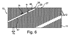
本発明に係るアプリケータのアプリケータ部材10のコア11の展開された表面が、図5に示されており、塗布要素12がコア11に取り付けられるところの、塗布要素12の基部19が、この図に示されている。塗布要素12の螺旋列26、27と塗布要素を有さない螺旋ストリップ25は各々、線Zに沿って延在し、コア11の長手方向軸Xとのその角度は、螺旋角度と一致する。
The developed surface of the
図2Aおよび5に示されるように、2つの隣接する、塗布要素の螺旋列26、27の間の間隔erは、列の向きに垂直の方向に測定され、かつ、塗布要素を有さないストリップ25を区画する2つの列26,27内の塗布要素12の側面12aに沿って延びる線の間をコア11において測定される距離に対応し、上記間隔erは、これらの螺旋列内の塗布要素12間の平均間隔eeよりも大きく、この間隔eeは、この場合には、列内の全ての塗布要素で同じである。
As shown in FIGS. 2A and 5, two adjacent spacing e r between
2つの隣接する、塗布要素の螺旋列26、27間の間隔erは、さらに、塗布要素12の最大横断寸法Deよりも大きい。
Two adjacent spacing e r between the
間隔erは、好ましくは、1つの螺旋列内の2つの塗布要素12間の間隔eeの1.1〜1.8倍、より好ましくは1.3〜1.6倍であり、記載された例では、1つの螺旋列内の2つの塗布要素12間の間隔eeの1.4倍に等しい。間隔erは、好ましくは、0.5mm〜1.5mmであり、例えば、0.7mmに等しい。
Distance e r is preferably 1.1 to 1.8 times the spacing e e between the two coating components in one
さらに、1つの螺旋列26内の2つの隣接する塗布要素12間の間隔は、コア11において、隣接する塗布要素12の隣接する側面12a間を測定されるとき、塗布要素12の最大横断寸法Deよりも小さく、特にこの場合には、コア11の全長Lに沿って、それらの基部19の直径よりも小さい。
Furthermore, the distance between two
上記間隔は、好ましくは、塗布要素の最大横断寸法Deの0.3〜0.9倍、より好ましくは0.5〜0.8倍であり、当該の例では、最大横断寸法Deの0.7倍に等しい。上記間隔は、好ましくは、0.2mm〜0.8mmであり、例えば、0.4mmに等しい。 The spacing is preferably 0.3 to 0.9 times the maximum transverse dimension D e of the applicator element, more preferably from 0.5 to 0.8 times, in this example, the largest transverse dimension D e Equal to 0.7 times. The spacing is preferably between 0.2 mm and 0.8 mm, for example equal to 0.4 mm.
本発明に係るアプリケータ3が用いられる場合には、アプリケータ部材10が、拭き取り部材6を通過した後に、塗布要素を有さない螺旋ストリップ25の存在に起因する、螺旋列間の比較的大きな間隔が、ストリップ25の領域内で、上記列間の製品Pのリザーバを形成する領域を得ること、よって、塗布の間のまつ毛および/または眉毛の満足のいく堆積を得ることを可能にする。
When the applicator 3 according to the invention is used, the
記載された例のように、1つの螺旋列26内の2つの隣接する塗布要素12間の間隔eeは、好ましくは一定であり、塗布要素の各螺旋列において同一であり、塗布要素12の全ては、例えば、それらの基部19にて同じ直径を有する。螺旋ストリップを区画する2つの螺旋列間の間隔erは、同様に、コア11の全ての箇所にて一定である。
As the example described, the interval e e between two
図示されていない変形例において、間隔eeおよびerは可変である。2つの隣接する塗布要素12間の間隔eeは、1つの同じ列内で異なり得、および/または、列ごとに異なり得る。間隔erは、いくつかの螺旋列間で異なり得る。
In a variant not shown, the intervals ee and err are variable. Distance e e between the
塗布要素を有さない螺旋ストリップ25の数は、好ましくは、1〜10個であり、記載された例では、6個に等しい。 The number of spiral strips 25 without application elements is preferably between 1 and 10 and in the example described is equal to 6.
記載された例では、塗布要素12の螺旋列は、全て同じであり、かつ、コア11の長手方向軸Xの周りでの360°/n(nは列の数)、すなわち例えば60°の回転によって互いに鏡像の関係にある。
In the example described, the spiral rows of the
塗布要素12の各螺旋列は、25〜40個、例えば約35個の塗布要素を有する。
Each helical row of
アプリケータ部材10は、好ましくは、100〜400個、例えば約200個の塗布要素12を有する。アプリケータ部材10が、示されるように、螺旋列内に配置されるもの以外の塗布要素12を有さないことが可能である。
The
これまで記載された例では、塗布要素を有さない複数の螺旋ストリップ25が、塗布要素12の螺旋列の間に設けられている。図6に示される変形例において、アプリケータ部材10は、塗布要素を有さない1つの螺旋ストリップ25を有する。
In the examples described so far, a plurality of spiral strips 25 without application elements are provided between the helical rows of
当該の例ではその基部19の直径である、塗布要素12の最大横断寸法Deは、0.5mm〜1mmであり得、例えば、0.5mmに等しい。
In this example the diameter of its base 19, the maximum transverse dimension D e of the
先行技術に係るアプリケータのアプリケータ部材110のコア111の展開面が、図7に示されており、塗布要素112がコア111に取り付けられているところの、塗布要素112の基部119が、この図に描かれている。塗布要素112の螺旋列126,127は各々、線Z’に沿って延在する。
The developed surface of the
このアプリケータ部材110は、2つの隣接する螺旋列126,127間の間隔er’を有する。上記間隔er’は、上記列の向きに垂直の方向に測定され、かつ、上記2つの列126,127内の塗布要素112の側面112aに沿って延びる線の間をコア111において測定される距離に対応する。この間隔er’は、これらの列内の2つの隣接する塗布要素間の間隔ee’よりも小さく、かつ塗布要素112の最大横断寸法De’よりも小さい。アプリケータ部材110の拭き取り後に製品Pのリザーバを形成する領域を得る可能性は、よって限られる。
The
図1〜6および8の本発明に係るアプリケータの例において、塗布要素12は、コア11上のそれらの位置に応じて異なる高さhを有する。図3Aに示されるように、長手方向軸X上の1つの同じ軸方向位置を占める塗布要素12により形成される冠部16の塗布要素12は、コアの近位端から開始する特定のランク(rank)で始まる、コアの自由端の方向における隣接する冠部17における塗布要素12の高さ以上の高さhを有することができる。示されていない一変形例では、塗布要素12は、全て同じ高さhである。さらなる変形例において、塗布要素12は、コア11に沿って他の何らかのやり方で異なる高さhを有し、アプリケータ部材10のエンベロープ面は、任意の形状、特に円筒形、円筒円錐形、双円錐形、タマゴ形、魚形、ピーナッツ形、球形、弓形、等の形状を有することが可能である。
In the example of the applicator according to the invention of FIGS. 1-6 and 8, the
図4に見られるように、冠部16の塗布要素12の自由端を通過する円の最大直径φ1は、5mm〜15mmであり得、例えば、8mmに等しい。
As can be seen in FIG. 4, the maximum diameter φ1 of the circle passing through the free end of the
2つの隣接する冠部16および17の間のコア11の長手方向軸Xの周りの角度オフセットαは、10°〜20°であり得、例えば、図4に示される例のように、15°に等しい。
The angular offset α around the longitudinal axis X of the core 11 between two
アプリケータ部材10は、その近位端20および遠位端21の近くで、より低い高さを有する塗布要素12を有することができる。
The
図3に示されるように、1つの長手方向列36内、すなわち1つの長手方向断面内で、塗布要素12の高さhは、コア13の自由端に向かって増加し、次いで減少することができる。
As shown in FIG. 3, within one
塗布要素12の高さhは、例えば、0.5mm〜5mmである。
The height h of the
塗布要素12の横断寸法は、それらの基部19からそれらの自由端22に向かって減少することができる。
The transverse dimension of the
塗布要素12の自由端22における曲率半径reは、好ましくは、0.4mm〜0.7mmであり、例えば、0.5mmに等しい。
The radius of curvature r e at the
図3Aおよび5に示されるように、1つの同じ長手方向列36内の2つの隣接する塗布要素12間の距離deは、それらの自由端22間で測定され、2mm〜3.5mmであり得、例えば、3mmに等しい。1つの同じ長手方向列内の2つの隣接する塗布要素12間の距離dbは、コア11の領域内の、隣接する塗布要素の隣接する側面12a間で測定され、2mm〜3mmであり得、例えば、2.5mmに等しい。
As shown in FIGS. 3A and 5, the distance d e between two
図3および3Aに示されるように、1つの同じ長手方向列36内の2つの隣接する塗布要素間に、投影図において、異なる長手方向列に属する3つの塗布要素12が存在し得る。
As shown in FIGS. 3 and 3A, there may be three
塗布要素12は、示された例では、それらの基部において円形断面を有する円錐形を有するスパイクにより構成されている。しかし、本発明は、円錐スパイクの形態の塗布要素に限定されず、例えば平らな断面を有する、他の形状のスパイクも可能である。
The
図9〜11に示される変形例では、コア11は複数のキャビティ13を有し、それらは各々、コア11の長手方向軸に対する横軸を有する。
In the variant shown in FIGS. 9 to 11, the
キャビティ13は、塗布要素を有さない螺旋ストリップ25に沿って配置され、よって、キャビティの複数の螺旋列で配置される。記載された例では、キャビティの各列は、塗布要素を有さない螺旋ストリップ25の幅の中間に配置される。
The
図11に示されるように、半球形のくぼみにより構成されるキャビティは、コア11の軸に垂直の断面にて、半円形の断面を有するが、本発明は、特定の形状のキャビティに限定されない。 As shown in FIG. 11, the cavity constituted by the hemispherical depression has a semicircular cross section in a cross section perpendicular to the axis of the core 11, but the present invention is not limited to a specific shape cavity. .
当該の例において、キャビティ13は、開口14によってコア11内に開いており、開口の直径であるその最大寸法Dgは、塗布要素12の最大横断寸法Deに等しい。示されていない変形例では、開口14の最大寸法Dgは、塗布要素12の最大横断寸法Deとは異なる。
In the example of the
記載された例では、キャビティ13は全て、同じ最大寸法Dgを有する開口14によりコア11内に開いている。一変形例では、開口14の最大寸法Dgは、キャビティの螺旋列内でおよび/または列ごとに異なる。
In the described example, it is open in the
キャビティの螺旋列28内の2つのキャビティ13間の間隔egは、記載された例では一定であり、キャビティの全ての列で同じである。示されていない一変形例では、キャビティの螺旋列内の2つのキャビティ13間の間隔egは、1つの同じ列内でおよび/または列ごとに異なる。
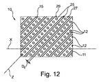
Distance e g between the two
図12に示される一変形例では、コア11は、塗布要素を有さない螺旋ストリップ25に沿ってかつ塗布要素12の2つの螺旋列間に配置された、連続する螺旋溝15の形態の少なくとも1つのキャビティを有する。溝の最大横断寸法Dgは、コア11におけるその幅であり、それを囲む螺旋列内の塗布要素12の最大横断寸法Deに等しい。
In one variant shown in FIG. 12, the
本発明は、ここまで記載された例に限定されない。 The invention is not limited to the examples described so far.
示された例の特徴を、示されていない変形例へと組み合わせることは、本発明の範囲からの逸脱を構成しない。 Combining the features of the examples shown with variations not shown does not constitute a departure from the scope of the invention.
記載された例では、塗布要素12は、全て同じ最大横断寸法Deを有する。示されていない一変形例では、塗布要素12の最大横断寸法Deは、例えば、塗布要素の同じ螺旋列内でおよび/または列ごとに異なる。
In the described embodiment, the
塗布要素12は、静菌性を有するおよび/または滑りを促進するおよび/または磁力がある材料を含んでもよい。
The
アプリケータ3が、使用中に振動に晒され、および/または加熱され、すなわち、加熱要素を有し、および/または回転可能であってもよい。また、アプリケータ部材10が、振動可能でありかつ加熱される、または単に振動可能である、または単に加熱される、または単に回転可能であることも可能である。アプリケータが回転可能である場合には、握り部材9は、軸体を回転させるための電気モータを収容してもよい。
The applicator 3 may be subjected to vibration and / or heated during use, i.e. having a heating element and / or rotatable. It is also possible for the
「有する」という表現は、「少なくとも1つを有する」と同義であると理解されるべきである。 The expression “having” should be understood as synonymous with “having at least one”.
Claims (23)
軸体(8)、および
軸体(8)の一端にあるアプリケータ部材(10)
を有し、ここで、アプリケータ部材(10)は、材料を成形することにより製造されており、かつ、
長手方向軸(X)に沿って延在する、ねじれていないコア(11)、および
コア(11)により保持され、かつコア(11)の長手方向軸(X)の周りに複数の螺旋列(26,27)で配置された塗布要素(12)
を有し、
アプリケータ部材(10)は、少なくとも1つの螺旋ストリップ(25)を有し、該螺旋ストリップ(25)は、コア(11)の長手方向軸(X)の周りに半回転を超えて延在し、塗布要素を有さず、かつ互いに平行に延在する2つの隣接する、塗布要素(11)の螺旋列(26,27)によって区画され、
これら2つの隣接する、塗布要素(11)の螺旋列(26,27)間の間隔(er)は、これらの螺旋列内の塗布要素(12)間の平均間隔(ee)よりも大きく、間隔(e r )が間隔(e e )の1.1〜1.8倍であり、
1つの螺旋列(26)内の2つの隣接する塗布要素(12)間の間隔が一定である、
上記アプリケータ(3)。 An applicator (3) for applying a cosmetic product (P) for makeup or care to the eyelashes and / or eyebrows,
Shaft (8), and applicator member (10) at one end of the shaft (8)
Where the applicator member (10) is manufactured by molding a material, and
An untwisted core (11) extending along the longitudinal axis (X), and a plurality of rows of spirals (held by the core (11) and around the longitudinal axis (X) of the core (11) ( 26, 27) Application elements (12) arranged in
Have
The applicator member (10) has at least one spiral strip (25) that extends more than half a revolution around the longitudinal axis (X) of the core (11). Defined by two adjacent helical rows (26, 27) of application elements (11), which have no application elements and extend parallel to each other,
The spacing (e r ) between the two adjacent spiral rows (26, 27) of the application elements (11) is greater than the average spacing (e e ) between the application elements (12) in these spiral rows. And the interval (e r ) is 1.1 to 1.8 times the interval (e e ),
The spacing between two adjacent application elements (12) in one spiral row (26) is constant;
The applicator (3).
Applications Claiming Priority (3)
| Application Number | Priority Date | Filing Date | Title |
|---|---|---|---|
| FR1356128A FR3007629B1 (en) | 2013-06-26 | 2013-06-26 | DEVICE FOR APPLYING A COSMETIC PRODUCT |
| FR1356128 | 2013-06-26 | ||
| PCT/IB2014/062588 WO2014207673A1 (en) | 2013-06-26 | 2014-06-25 | Device for applying a cosmetic product |
Publications (2)
| Publication Number | Publication Date |
|---|---|
| JP2016523650A JP2016523650A (en) | 2016-08-12 |
| JP6587611B2 true JP6587611B2 (en) | 2019-10-09 |
Family
ID=49274826
Family Applications (1)
| Application Number | Title | Priority Date | Filing Date |
|---|---|---|---|
| JP2016522931A Active JP6587611B2 (en) | 2013-06-26 | 2014-06-25 | Device for applying cosmetic products |
Country Status (8)
| Country | Link |
|---|---|
| US (1) | US9907386B2 (en) |
| EP (1) | EP3013175B1 (en) |
| JP (1) | JP6587611B2 (en) |
| KR (1) | KR20160024390A (en) |
| CN (1) | CN105338852B (en) |
| ES (1) | ES2874251T3 (en) |
| FR (1) | FR3007629B1 (en) |
| WO (1) | WO2014207673A1 (en) |
Families Citing this family (10)
| Publication number | Priority date | Publication date | Assignee | Title |
|---|---|---|---|---|
| FR3017783B1 (en) * | 2014-02-24 | 2016-02-26 | Albea Services | APPLICATOR FOR COSMETIC PRODUCT, IN PARTICULAR FOR MASCARA AND ASSOCIATED APPLICATOR ASSEMBLY |
| FR3026283B1 (en) * | 2014-09-30 | 2016-12-09 | Oreal | APPLICATOR OF A COSMETIC, MAKE-UP OR CARE PRODUCT, ON LASHES AND / OR EYEBROWS |
| JP2019525816A (en) * | 2016-06-08 | 2019-09-12 | ソシエテ アンデュストリエル ドゥ マティエール プラスティック | Applicator device for applying liquid or paste keratin fibers |
| FR3060278B1 (en) | 2016-12-21 | 2019-09-27 | L V M H Recherche | COSMETIC PRODUCT APPLICATOR DEVICE WITH FLEXIBLE APPLICATOR ELEMENT |
| FR3070842B1 (en) * | 2017-09-12 | 2021-07-16 | Oreal | COSMETIC APPLICATOR |
| FR3070841B1 (en) | 2017-09-12 | 2021-07-16 | Oreal | COSMETIC APPLICATOR |
| FR3070839B1 (en) | 2017-09-12 | 2025-04-11 | Oreal | COSMETIC APPLICATOR |
| WO2020095456A1 (en) * | 2018-11-09 | 2020-05-14 | 株式会社エイエムジー | Mascara comb |
| FR3090297B1 (en) * | 2018-12-19 | 2021-10-15 | Oreal | Spiral cosmetic applicator |
| IT202100002843A1 (en) * | 2021-02-09 | 2022-08-09 | Brivaplast Srl | COSMETICS APPLICATOR IN TWO COMPONENTS |
Family Cites Families (28)
| Publication number | Priority date | Publication date | Assignee | Title |
|---|---|---|---|---|
| US4635659A (en) | 1984-01-05 | 1987-01-13 | Spatz Laboratories, Inc. | Mascara applicator |
| JPS6172223A (en) * | 1984-09-17 | 1986-04-14 | Yokogawa Medical Syst Ltd | Crt multiframe photographing device |
| US4694429A (en) * | 1984-11-29 | 1987-09-15 | Kabushiki Kaisha Toshiba | Semiconductor memory device |
| GB8707086D0 (en) * | 1987-03-25 | 1987-04-29 | Cole R D | Cosmetics applicator |
| EP0474934A1 (en) | 1990-09-14 | 1992-03-18 | Aceworld Plastics Co Ltd | Brush bristle arrangement |
| FR2724296B1 (en) * | 1994-09-12 | 1997-06-20 | Sanofi Sa | APPLICATOR ASSEMBLY FOR A COSMETIC PRODUCT, SUCH AS A MASCARA |
| FR2730910B1 (en) * | 1995-02-23 | 1997-04-11 | Oreal | COSMETIC APPLICATOR |
| US20060070635A1 (en) | 2004-10-01 | 2006-04-06 | The Procter & Gamble Company | Cosmetic brush comprising bristles having external depressions |
| FR2909532B1 (en) | 2006-12-12 | 2009-11-13 | Oreal | APPLICATOR FOR APPLYING A PRODUCT ON LACQUERS OR EYEBROWS. |
| FR2912620B1 (en) * | 2007-02-21 | 2010-08-13 | Chanel Parfums Beaute | METHOD FOR MANUFACTURING A COSMETIC PRODUCT APPLICATOR, APPLICATOR, PACKAGE COMPRISING THE APPLICATOR, AND LOT OF APPLICATORS |
| FR2913572B1 (en) | 2007-03-16 | 2009-06-05 | Chanel Parfums Beaute Soc Par | APPLICATOR FOR APPLYING A PRODUCT ON THE LASHES |
| FR2918547B1 (en) * | 2007-07-11 | 2011-04-01 | Chanel Parfums Beaute | APPLICATOR FOR MAKE UP OF LASHES AND / OR EYEILS WITH A SILL. |
| US8985883B2 (en) * | 2007-07-30 | 2015-03-24 | The Procter & Gamble Company | Control surfaces for applicator with moveable applicator head |
| FR2983689A1 (en) * | 2007-10-23 | 2013-06-14 | Oreal | APPLICATOR TO COMBINE OR APPLY A PRODUCT ON LACQUERS AND / OR EYEBROWS |
| FR2939618B1 (en) * | 2008-12-11 | 2011-05-20 | Oreal | APPLICATOR FOR APPLYING A COSMETIC, MAKE-UP OR CARE PRODUCT ON KERATINIC MATERIALS |
| DE102009013233A1 (en) * | 2009-03-17 | 2010-09-23 | Oekametall Oehlhorn Gmbh & Co. Kg | Applicator for applying a cosmetic and / or pharmaceutical composition, in particular mascara |
| FR2943226B1 (en) * | 2009-03-20 | 2011-06-03 | Oreal | APPLICATOR FOR APPLYING A COSMETIC, MAKE-UP OR CARE PRODUCT, AND METHOD OF MANUFACTURE |
| FR2945921B1 (en) * | 2009-05-28 | 2014-07-25 | Rexam Beauty & Closures Inc | COSMETIC CONTAINER |
| KR200455309Y1 (en) * | 2009-07-21 | 2011-08-31 | 유강식 | Tubular Mascara Container |
| FR2951359B1 (en) * | 2009-10-15 | 2019-12-27 | L'oreal | DEVICE FOR APPLYING A PRODUCT TO EYELASHES OR EYEBROWS. |
| JP5527652B2 (en) * | 2009-12-17 | 2014-06-18 | フィグラ株式会社 | Liquid cosmetic applicator |
| JP5507676B2 (en) * | 2010-05-14 | 2014-05-28 | 株式会社新和製作所 | Makeup brush |
| FR2962015B1 (en) | 2010-07-01 | 2012-08-31 | Oreal | APPLICATOR TO APPLY A PRODUCT ON THE LASHES. |
| KR101237030B1 (en) * | 2010-12-03 | 2013-02-25 | (주)레이원 | Eyelash shaping and toiletries |
| DE202011002793U1 (en) | 2011-02-16 | 2012-06-12 | Geka Gmbh | Applicator with tubular, overmolded core element |
| JP5484535B2 (en) * | 2011-09-02 | 2014-05-07 | 株式会社 資生堂 | Makeup tools |
| FR2983045B1 (en) * | 2011-11-24 | 2014-02-07 | Chanel Parfums Beaute | APPLICATOR FOR APPLYING A PRODUCT TO EYELASHES OR EYCILS THAT INCLUDES INJECTION MOLDED HAIR |
| DE202014101055U1 (en) * | 2014-03-10 | 2015-06-12 | Geka Gmbh | Applicator with separately manufactured and mounted bristle plates |
-
2013
- 2013-06-26 FR FR1356128A patent/FR3007629B1/en not_active Expired - Fee Related
-
2014
- 2014-06-25 CN CN201480037149.5A patent/CN105338852B/en active Active
- 2014-06-25 US US14/901,652 patent/US9907386B2/en active Active
- 2014-06-25 WO PCT/IB2014/062588 patent/WO2014207673A1/en not_active Ceased
- 2014-06-25 JP JP2016522931A patent/JP6587611B2/en active Active
- 2014-06-25 EP EP14744180.2A patent/EP3013175B1/en active Active
- 2014-06-25 KR KR1020167001971A patent/KR20160024390A/en not_active Ceased
- 2014-06-25 ES ES14744180T patent/ES2874251T3/en active Active
Also Published As
| Publication number | Publication date |
|---|---|
| US9907386B2 (en) | 2018-03-06 |
| KR20160024390A (en) | 2016-03-04 |
| FR3007629B1 (en) | 2015-08-07 |
| EP3013175B1 (en) | 2021-04-21 |
| EP3013175A1 (en) | 2016-05-04 |
| CN105338852A (en) | 2016-02-17 |
| WO2014207673A1 (en) | 2014-12-31 |
| CN105338852B (en) | 2018-12-04 |
| ES2874251T3 (en) | 2021-11-04 |
| US20160143419A1 (en) | 2016-05-26 |
| JP2016523650A (en) | 2016-08-12 |
| FR3007629A1 (en) | 2015-01-02 |
Similar Documents
| Publication | Publication Date | Title |
|---|---|---|
| JP6587611B2 (en) | Device for applying cosmetic products | |
| US9723911B2 (en) | Device for applying a composition to the eyelashes or the eyebrows | |
| US9125474B2 (en) | Applicator for applying a composition to the eyelashes or the eyebrows | |
| US8944714B2 (en) | Applicator for combing the eyelashes and/or eyebrows or for applying a composition thereto | |
| KR102306530B1 (en) | Applicator for applying a product to the eyelashes and/or eyebrows | |
| CN110650652B (en) | Applicator for applying product to lashes | |
| KR20160003062A (en) | Applicator for applying a product to the eyelashes and/or eyebrows | |
| KR102255086B1 (en) | Applicator for applying a cosmetic, makeup or care, product to the eyelashes and/or eyebrows | |
| JP2019525816A (en) | Applicator device for applying liquid or paste keratin fibers | |
| CN114680445A (en) | Applicator for applying a product to eyelashes | |
| KR20190049945A (en) | Applicator for applying a cosmetic, makeup or care, product to the eyelashes and/or eyebrows | |
| WO2013153525A1 (en) | Applicator for applying a cosmetic product to the eyelashed and/or eyebrows | |
| US11445800B2 (en) | Applicator for applying a cosmetic, makeup or care, product to the eyelashes and/or eyebrows | |
| EP3206528B1 (en) | Applicator for applying a cosmetic, makeup or care product to the eyelashes and/or eyebrows | |
| CN105307537B (en) | Applicator for applying product to eyelashes or eyebrows | |
| CN107105880A (en) | Applicator for applying beauty, makeup or care products to eyelashes and/or eyebrows |
Legal Events
| Date | Code | Title | Description |
|---|---|---|---|
| A621 | Written request for application examination |
Free format text: JAPANESE INTERMEDIATE CODE: A621 Effective date: 20170426 |
|
| A131 | Notification of reasons for refusal |
Free format text: JAPANESE INTERMEDIATE CODE: A131 Effective date: 20180418 |
|
| A521 | Request for written amendment filed |
Free format text: JAPANESE INTERMEDIATE CODE: A523 Effective date: 20180717 |
|
| A131 | Notification of reasons for refusal |
Free format text: JAPANESE INTERMEDIATE CODE: A131 Effective date: 20190116 |
|
| A601 | Written request for extension of time |
Free format text: JAPANESE INTERMEDIATE CODE: A601 Effective date: 20190404 |
|
| A521 | Request for written amendment filed |
Free format text: JAPANESE INTERMEDIATE CODE: A523 Effective date: 20190716 |
|
| TRDD | Decision of grant or rejection written | ||
| A01 | Written decision to grant a patent or to grant a registration (utility model) |
Free format text: JAPANESE INTERMEDIATE CODE: A01 Effective date: 20190819 |
|
| A61 | First payment of annual fees (during grant procedure) |
Free format text: JAPANESE INTERMEDIATE CODE: A61 Effective date: 20190910 |
|
| R150 | Certificate of patent or registration of utility model |
Ref document number: 6587611 Country of ref document: JP Free format text: JAPANESE INTERMEDIATE CODE: R150 |
|
| R250 | Receipt of annual fees |
Free format text: JAPANESE INTERMEDIATE CODE: R250 |
|
| R250 | Receipt of annual fees |
Free format text: JAPANESE INTERMEDIATE CODE: R250 |
|
| R250 | Receipt of annual fees |
Free format text: JAPANESE INTERMEDIATE CODE: R250 |
|
| R250 | Receipt of annual fees |
Free format text: JAPANESE INTERMEDIATE CODE: R250 |