JP6572202B2 - End effector of surgical robot manipulator - Google Patents
End effector of surgical robot manipulator Download PDFInfo
- Publication number
- JP6572202B2 JP6572202B2 JP2016503280A JP2016503280A JP6572202B2 JP 6572202 B2 JP6572202 B2 JP 6572202B2 JP 2016503280 A JP2016503280 A JP 2016503280A JP 2016503280 A JP2016503280 A JP 2016503280A JP 6572202 B2 JP6572202 B2 JP 6572202B2
- Authority
- JP
- Japan
- Prior art keywords
- cutting accessory
- end effector
- shaft
- tip tube
- axis
- Prior art date
- Legal status (The legal status is an assumption and is not a legal conclusion. Google has not performed a legal analysis and makes no representation as to the accuracy of the status listed.)
- Active
Links
Images


Classifications
-
- A—HUMAN NECESSITIES
- A61—MEDICAL OR VETERINARY SCIENCE; HYGIENE
- A61B—DIAGNOSIS; SURGERY; IDENTIFICATION
- A61B17/00—Surgical instruments, devices or methods
- A61B17/32—Surgical cutting instruments
- A61B17/320016—Endoscopic cutting instruments, e.g. arthroscopes, resectoscopes
- A61B17/32002—Endoscopic cutting instruments, e.g. arthroscopes, resectoscopes with continuously rotating, oscillating or reciprocating cutting instruments
-
- A—HUMAN NECESSITIES
- A61—MEDICAL OR VETERINARY SCIENCE; HYGIENE
- A61B—DIAGNOSIS; SURGERY; IDENTIFICATION
- A61B34/00—Computer-aided surgery; Manipulators or robots specially adapted for use in surgery
- A61B34/30—Surgical robots
-
- A—HUMAN NECESSITIES
- A61—MEDICAL OR VETERINARY SCIENCE; HYGIENE
- A61B—DIAGNOSIS; SURGERY; IDENTIFICATION
- A61B34/00—Computer-aided surgery; Manipulators or robots specially adapted for use in surgery
- A61B34/70—Manipulators specially adapted for use in surgery
- A61B34/76—Manipulators having means for providing feel, e.g. force or tactile feedback
-
- A—HUMAN NECESSITIES
- A61—MEDICAL OR VETERINARY SCIENCE; HYGIENE
- A61B—DIAGNOSIS; SURGERY; IDENTIFICATION
- A61B50/00—Containers, covers, furniture or holders specially adapted for surgical or diagnostic appliances or instruments, e.g. sterile covers
- A61B50/10—Furniture specially adapted for surgical or diagnostic appliances or instruments
- A61B50/13—Trolleys, e.g. carts
-
- A—HUMAN NECESSITIES
- A61—MEDICAL OR VETERINARY SCIENCE; HYGIENE
- A61B—DIAGNOSIS; SURGERY; IDENTIFICATION
- A61B50/00—Containers, covers, furniture or holders specially adapted for surgical or diagnostic appliances or instruments, e.g. sterile covers
- A61B50/30—Containers specially adapted for packaging, protecting, dispensing, collecting or disposing of surgical or diagnostic appliances or instruments
- A61B50/36—Containers specially adapted for packaging, protecting, dispensing, collecting or disposing of surgical or diagnostic appliances or instruments for collecting or disposing of used articles
- A61B50/362—Containers specially adapted for packaging, protecting, dispensing, collecting or disposing of surgical or diagnostic appliances or instruments for collecting or disposing of used articles for sharps
-
- A—HUMAN NECESSITIES
- A61—MEDICAL OR VETERINARY SCIENCE; HYGIENE
- A61B—DIAGNOSIS; SURGERY; IDENTIFICATION
- A61B90/00—Instruments, implements or accessories specially adapted for surgery or diagnosis and not covered by any of the groups A61B1/00 - A61B50/00, e.g. for luxation treatment or for protecting wound edges
- A61B90/90—Identification means for patients or instruments, e.g. tags
-
- F—MECHANICAL ENGINEERING; LIGHTING; HEATING; WEAPONS; BLASTING
- F16—ENGINEERING ELEMENTS AND UNITS; GENERAL MEASURES FOR PRODUCING AND MAINTAINING EFFECTIVE FUNCTIONING OF MACHINES OR INSTALLATIONS; THERMAL INSULATION IN GENERAL
- F16D—COUPLINGS FOR TRANSMITTING ROTATION; CLUTCHES; BRAKES
- F16D1/00—Couplings for rigidly connecting two coaxial shafts or other movable machine elements
- F16D1/06—Couplings for rigidly connecting two coaxial shafts or other movable machine elements for attachment of a member on a shaft or on a shaft-end
- F16D1/08—Couplings for rigidly connecting two coaxial shafts or other movable machine elements for attachment of a member on a shaft or on a shaft-end with clamping hub; with hub and longitudinal key
- F16D1/0817—Couplings for rigidly connecting two coaxial shafts or other movable machine elements for attachment of a member on a shaft or on a shaft-end with clamping hub; with hub and longitudinal key with radial clamping due to rotation along an eccentric surface, e.g. arcuate wedging elements
-
- F—MECHANICAL ENGINEERING; LIGHTING; HEATING; WEAPONS; BLASTING
- F16—ENGINEERING ELEMENTS AND UNITS; GENERAL MEASURES FOR PRODUCING AND MAINTAINING EFFECTIVE FUNCTIONING OF MACHINES OR INSTALLATIONS; THERMAL INSULATION IN GENERAL
- F16D—COUPLINGS FOR TRANSMITTING ROTATION; CLUTCHES; BRAKES
- F16D1/00—Couplings for rigidly connecting two coaxial shafts or other movable machine elements
- F16D1/10—Quick-acting couplings in which the parts are connected by simply bringing them together axially
- F16D1/108—Quick-acting couplings in which the parts are connected by simply bringing them together axially having retaining means rotating with the coupling and acting by interengaging parts, i.e. positive coupling
- F16D1/116—Quick-acting couplings in which the parts are connected by simply bringing them together axially having retaining means rotating with the coupling and acting by interengaging parts, i.e. positive coupling the interengaging parts including a continuous or interrupted circumferential groove in the surface of one of the coupling parts
-
- F—MECHANICAL ENGINEERING; LIGHTING; HEATING; WEAPONS; BLASTING
- F16—ENGINEERING ELEMENTS AND UNITS; GENERAL MEASURES FOR PRODUCING AND MAINTAINING EFFECTIVE FUNCTIONING OF MACHINES OR INSTALLATIONS; THERMAL INSULATION IN GENERAL
- F16D—COUPLINGS FOR TRANSMITTING ROTATION; CLUTCHES; BRAKES
- F16D15/00—Clutches with wedging balls or rollers or with other wedgeable separate clutching members
-
- F—MECHANICAL ENGINEERING; LIGHTING; HEATING; WEAPONS; BLASTING
- F16—ENGINEERING ELEMENTS AND UNITS; GENERAL MEASURES FOR PRODUCING AND MAINTAINING EFFECTIVE FUNCTIONING OF MACHINES OR INSTALLATIONS; THERMAL INSULATION IN GENERAL
- F16J—PISTONS; CYLINDERS; SEALINGS
- F16J15/00—Sealings
- F16J15/16—Sealings between relatively-moving surfaces
- F16J15/32—Sealings between relatively-moving surfaces with elastic sealings, e.g. O-rings
- F16J15/3248—Sealings between relatively-moving surfaces with elastic sealings, e.g. O-rings provided with casings or supports
- F16J15/3252—Sealings between relatively-moving surfaces with elastic sealings, e.g. O-rings provided with casings or supports with rigid casings or supports
- F16J15/3256—Sealings between relatively-moving surfaces with elastic sealings, e.g. O-rings provided with casings or supports with rigid casings or supports comprising two casing or support elements, one attached to each surface, e.g. cartridge or cassette seals
-
- A—HUMAN NECESSITIES
- A61—MEDICAL OR VETERINARY SCIENCE; HYGIENE
- A61B—DIAGNOSIS; SURGERY; IDENTIFICATION
- A61B17/00—Surgical instruments, devices or methods
- A61B17/16—Instruments for performing osteoclasis; Drills or chisels for bones; Trepans
- A61B17/1613—Component parts
- A61B17/1615—Drill bits, i.e. rotating tools extending from a handpiece to contact the worked material
-
- A—HUMAN NECESSITIES
- A61—MEDICAL OR VETERINARY SCIENCE; HYGIENE
- A61B—DIAGNOSIS; SURGERY; IDENTIFICATION
- A61B17/00—Surgical instruments, devices or methods
- A61B17/16—Instruments for performing osteoclasis; Drills or chisels for bones; Trepans
- A61B17/1613—Component parts
- A61B17/162—Chucks or tool parts which are to be held in a chuck
-
- A—HUMAN NECESSITIES
- A61—MEDICAL OR VETERINARY SCIENCE; HYGIENE
- A61B—DIAGNOSIS; SURGERY; IDENTIFICATION
- A61B17/00—Surgical instruments, devices or methods
- A61B17/16—Instruments for performing osteoclasis; Drills or chisels for bones; Trepans
- A61B17/1613—Component parts
- A61B17/1622—Drill handpieces
- A61B17/1624—Drive mechanisms therefor
-
- A—HUMAN NECESSITIES
- A61—MEDICAL OR VETERINARY SCIENCE; HYGIENE
- A61B—DIAGNOSIS; SURGERY; IDENTIFICATION
- A61B17/00—Surgical instruments, devices or methods
- A61B17/16—Instruments for performing osteoclasis; Drills or chisels for bones; Trepans
- A61B17/1613—Component parts
- A61B17/1626—Control means; Display units
-
- A—HUMAN NECESSITIES
- A61—MEDICAL OR VETERINARY SCIENCE; HYGIENE
- A61B—DIAGNOSIS; SURGERY; IDENTIFICATION
- A61B17/00—Surgical instruments, devices or methods
- A61B2017/00017—Electrical control of surgical instruments
-
- A—HUMAN NECESSITIES
- A61—MEDICAL OR VETERINARY SCIENCE; HYGIENE
- A61B—DIAGNOSIS; SURGERY; IDENTIFICATION
- A61B17/00—Surgical instruments, devices or methods
- A61B2017/00017—Electrical control of surgical instruments
- A61B2017/00022—Sensing or detecting at the treatment site
- A61B2017/00039—Electric or electromagnetic phenomena other than conductivity, e.g. capacity, inductivity, Hall effect
-
- A—HUMAN NECESSITIES
- A61—MEDICAL OR VETERINARY SCIENCE; HYGIENE
- A61B—DIAGNOSIS; SURGERY; IDENTIFICATION
- A61B17/00—Surgical instruments, devices or methods
- A61B2017/00017—Electrical control of surgical instruments
- A61B2017/00022—Sensing or detecting at the treatment site
- A61B2017/00057—Light
-
- A—HUMAN NECESSITIES
- A61—MEDICAL OR VETERINARY SCIENCE; HYGIENE
- A61B—DIAGNOSIS; SURGERY; IDENTIFICATION
- A61B17/00—Surgical instruments, devices or methods
- A61B2017/00367—Details of actuation of instruments, e.g. relations between pushing buttons, or the like, and activation of the tool, working tip, or the like
-
- A—HUMAN NECESSITIES
- A61—MEDICAL OR VETERINARY SCIENCE; HYGIENE
- A61B—DIAGNOSIS; SURGERY; IDENTIFICATION
- A61B17/00—Surgical instruments, devices or methods
- A61B2017/0042—Surgical instruments, devices or methods with special provisions for gripping
-
- A—HUMAN NECESSITIES
- A61—MEDICAL OR VETERINARY SCIENCE; HYGIENE
- A61B—DIAGNOSIS; SURGERY; IDENTIFICATION
- A61B17/00—Surgical instruments, devices or methods
- A61B2017/00477—Coupling
-
- A—HUMAN NECESSITIES
- A61—MEDICAL OR VETERINARY SCIENCE; HYGIENE
- A61B—DIAGNOSIS; SURGERY; IDENTIFICATION
- A61B17/00—Surgical instruments, devices or methods
- A61B2017/00681—Aspects not otherwise provided for
- A61B2017/00738—Aspects not otherwise provided for part of the tool being offset with respect to a main axis, e.g. for better view for the surgeon
-
- A—HUMAN NECESSITIES
- A61—MEDICAL OR VETERINARY SCIENCE; HYGIENE
- A61B—DIAGNOSIS; SURGERY; IDENTIFICATION
- A61B17/00—Surgical instruments, devices or methods
- A61B17/16—Instruments for performing osteoclasis; Drills or chisels for bones; Trepans
- A61B17/1644—Instruments for performing osteoclasis; Drills or chisels for bones; Trepans using fluid other than turbine drive fluid
- A61B2017/1651—Instruments for performing osteoclasis; Drills or chisels for bones; Trepans using fluid other than turbine drive fluid for cooling
-
- A—HUMAN NECESSITIES
- A61—MEDICAL OR VETERINARY SCIENCE; HYGIENE
- A61B—DIAGNOSIS; SURGERY; IDENTIFICATION
- A61B90/00—Instruments, implements or accessories specially adapted for surgery or diagnosis and not covered by any of the groups A61B1/00 - A61B50/00, e.g. for luxation treatment or for protecting wound edges
- A61B90/08—Accessories or related features not otherwise provided for
- A61B2090/0801—Prevention of accidental cutting or pricking
-
- A—HUMAN NECESSITIES
- A61—MEDICAL OR VETERINARY SCIENCE; HYGIENE
- A61B—DIAGNOSIS; SURGERY; IDENTIFICATION
- A61B90/00—Instruments, implements or accessories specially adapted for surgery or diagnosis and not covered by any of the groups A61B1/00 - A61B50/00, e.g. for luxation treatment or for protecting wound edges
- A61B90/08—Accessories or related features not otherwise provided for
- A61B2090/0807—Indication means
- A61B2090/0811—Indication means for the position of a particular part of an instrument with respect to the rest of the instrument, e.g. position of the anvil of a stapling instrument
-
- A—HUMAN NECESSITIES
- A61—MEDICAL OR VETERINARY SCIENCE; HYGIENE
- A61B—DIAGNOSIS; SURGERY; IDENTIFICATION
- A61B2217/00—General characteristics of surgical instruments
- A61B2217/002—Auxiliary appliance
- A61B2217/007—Auxiliary appliance with irrigation system
-
- A—HUMAN NECESSITIES
- A61—MEDICAL OR VETERINARY SCIENCE; HYGIENE
- A61B—DIAGNOSIS; SURGERY; IDENTIFICATION
- A61B90/00—Instruments, implements or accessories specially adapted for surgery or diagnosis and not covered by any of the groups A61B1/00 - A61B50/00, e.g. for luxation treatment or for protecting wound edges
- A61B90/90—Identification means for patients or instruments, e.g. tags
- A61B90/98—Identification means for patients or instruments, e.g. tags using electromagnetic means, e.g. transponders
-
- F—MECHANICAL ENGINEERING; LIGHTING; HEATING; WEAPONS; BLASTING
- F16—ENGINEERING ELEMENTS AND UNITS; GENERAL MEASURES FOR PRODUCING AND MAINTAINING EFFECTIVE FUNCTIONING OF MACHINES OR INSTALLATIONS; THERMAL INSULATION IN GENERAL
- F16D—COUPLINGS FOR TRANSMITTING ROTATION; CLUTCHES; BRAKES
- F16D1/00—Couplings for rigidly connecting two coaxial shafts or other movable machine elements
- F16D1/10—Quick-acting couplings in which the parts are connected by simply bringing them together axially
- F16D2001/103—Quick-acting couplings in which the parts are connected by simply bringing them together axially the torque is transmitted via splined connections
Landscapes
- Health & Medical Sciences (AREA)
- Surgery (AREA)
- Life Sciences & Earth Sciences (AREA)
- Engineering & Computer Science (AREA)
- Public Health (AREA)
- Veterinary Medicine (AREA)
- Biomedical Technology (AREA)
- Heart & Thoracic Surgery (AREA)
- Medical Informatics (AREA)
- Molecular Biology (AREA)
- Animal Behavior & Ethology (AREA)
- General Health & Medical Sciences (AREA)
- Nuclear Medicine, Radiotherapy & Molecular Imaging (AREA)
- General Engineering & Computer Science (AREA)
- Orthopedic Medicine & Surgery (AREA)
- Oral & Maxillofacial Surgery (AREA)
- Robotics (AREA)
- Mechanical Engineering (AREA)
- Dentistry (AREA)
- Pathology (AREA)
- Physics & Mathematics (AREA)
- Electromagnetism (AREA)
- Surgical Instruments (AREA)
- Manipulator (AREA)
Description
[関連出願の相互参照]
本特許出願は、2013年3月15日に出願された米国仮特許出願第61/798,729号の優先権及び全ての利得を主張するものであり、かかる仮特許出願は、参照することによって、ここに含まれるものとする。
[Cross-reference of related applications]
This patent application claims priority and all gains of US Provisional Patent Application No. 61 / 798,729, filed March 15, 2013, which is hereby incorporated by reference. And shall be included here.
[発明の分野]
本発明は、外科用ロボットマニピュレータにおける外科用エンドエフェクタに関する。特に、かかるエンドエフェクタは、先端チューブ(ノーズチューブ)と、該先端チューブに取り外し可能に係合される切断アクセサリとを備えるものとなっている。
[Field of the Invention]
The present invention relates to a surgical end effector in a surgical robot manipulator. In particular, the end effector includes a tip tube (nose tube) and a cutting accessory that is detachably engaged with the tip tube.
本発明は、加工端と軸に沿って延びるシャフトとを有する切断アクセサリを備える外科用ロボットマニピュレータのエンドエフェクタもまた含んでいる。駆動部材が、切断アクセサリのシャフトを回転可能に駆動するように構成されている。アクチュエータが、駆動部材を回転可能に駆動するように駆動部材に連結されている。クラッチアセンブリが、駆動部材によって支持され、かつ駆動部材に対して回転可能に構成されている。かかるクラッチアセンブリは、シャフトを駆動部材に選択的に係止するように、切断アクセサリのシャフトを軸に沿って受け入れる構成になっている。 The present invention also includes an end effector for a surgical robotic manipulator comprising a cutting accessory having a machining end and a shaft extending along the axis. A drive member is configured to rotatably drive the shaft of the cutting accessory. An actuator is coupled to the drive member to drive the drive member rotatably. The clutch assembly is supported by the drive member and configured to be rotatable with respect to the drive member. Such a clutch assembly is configured to receive the shaft of the cutting accessory along an axis so as to selectively lock the shaft to the drive member.
本発明は、外科用ロボットマニピュレータのエンドエフェクタを含んでいる。かかるエンドエフェクタは、シャフトと該シャフトに回転可能に連結されたシュラウド(shroud、覆い部材)とを有する切断アクセサリを備えている。先端チューブが、切断アクセサリを離脱可能に受け入れるように軸に沿って延びている。溝及び指状要素(finger、フィンガー要素)が、シュラウドと先端チューブとの間に配置されている。指状要素は、シュラウドに対して柔軟性(可撓性)を有し、かつ切断アクセサリを軸に沿って先端チューブに離脱可能に係止するように溝に係合する構成になっている。 The present invention includes an end effector of a surgical robot manipulator. Such an end effector includes a cutting accessory having a shaft and a shroud rotatably coupled to the shaft. A tip tube extends along the axis to removably receive the cutting accessory. Grooves and finger elements are disposed between the shroud and the tip tube. The finger element is flexible with respect to the shroud and is configured to engage the groove to releasably lock the cutting accessory along the axis to the tip tube.
本発明は、外科用ロボットマニピュレータを含んでいる。エンドエフェクタが、切断アクセサリを離脱可能に受け入れるように軸に沿って延びる先端チューブを備えている。かかる先端チューブは長孔を画定している。指状要素が先端チューブにて支持されている。かかる指状要素は、長孔と真っ直ぐに並ぶ突起を備えており、かつ切断アクセサリに係合するために長孔を貫通するように付勢されている。係止カラーが、指状要素に隣接して先端チューブに回転可能に支持されている。指状要素は、先端チューブと係止カラーとの間に配置されている。係止カラーは、突起が長孔内に押し込まれることを可能にするように、指状要素と選択的に真っ直ぐに並ぶ切欠きを備えている。 The present invention includes a surgical robot manipulator. The end effector includes a tip tube extending along the axis to removably receive the cutting accessory. Such a tip tube defines a slot. Finger elements are supported by the tip tube. Such a finger element has a protrusion that is aligned with the slot and is biased to penetrate the slot to engage the cutting accessory. A locking collar is rotatably supported on the tip tube adjacent to the finger element. The finger element is disposed between the tip tube and the locking collar. The locking collar includes a notch that is selectively aligned with the finger-like element to allow the protrusion to be pushed into the slot.
本発明は、外科用ロボットマニピュレータのエンドエフェクタを含んでいる。かかるエンドエフェクタは切断アクセサリを備えている。先端チューブが軸に沿って延びている。かかる先端チューブは、切断アクセサリに離脱可能に係合し、かつ切断アクセサリを回転可能に支持するように構成されている。軸方向接続体が先端チューブによって支持されている。軸方向接続体は、切断アクセサリを軸に沿って先端チューブに離脱可能に係止するように構成されている。駆動接続体が先端チューブによって支持されている。かかる駆動接続体は、切断アクセサリを回転可能に駆動するように切断アクセサリを受け入れる構成になっている。駆動接続体を先端チューブに対して回転させるように、アクチュエータが駆動接続体に連結されている。軸方向接続体は、切断アクセサリを保持する係止位置と切断アクセサリを解放する離脱位置との間で軸に沿って移動可能に構成されている。 The present invention includes an end effector of a surgical robot manipulator. Such an end effector includes a cutting accessory. A tip tube extends along the axis. The tip tube is configured to removably engage the cutting accessory and rotatably support the cutting accessory. An axial connector is supported by the tip tube. The axial connector is configured to releasably lock the cutting accessory along the axis to the tip tube. The drive connection is supported by the tip tube. Such a drive connection is configured to receive the cutting accessory so as to rotatably drive the cutting accessory. An actuator is coupled to the drive connection so as to rotate the drive connection relative to the tip tube. The axial connector is configured to be movable along the axis between a locking position for holding the cutting accessory and a disengagement position for releasing the cutting accessory.
本発明は、切断アクセサリを回転可能に駆動するように構成される外科用ロボットマニピュレータのエンドエフェクタもまた含んでいる。かかるエンドエフェクタは、軸に沿って延びる先端チューブを備えている。軸方向接続体が、先端チューブによって支持されている。先端チューブは、切断アクセサリを軸に沿って先端チューブに対して係止するように構成されている。駆動接続体が、先端チューブによって回転可能に支持されている。駆動接続体は、切断アクセサリを軸に沿って受け入れ、かつ切断アクセサリを回転可能に駆動するように構成されている。駆動接続体を先端チューブに対して回転させるように、アクチュエータが駆動接続体に連結されている。軸方向接続体は、切断アクセサリを保持する係止位置と切断アクセサリを解放する離脱位置との間で軸に沿って移動可能に構成されている。 The present invention also includes an end effector of a surgical robotic manipulator configured to rotatably drive a cutting accessory. Such an end effector includes a tip tube extending along the axis. An axial connector is supported by the tip tube. The tip tube is configured to lock the cutting accessory relative to the tip tube along the axis. A drive connector is rotatably supported by the tip tube. The drive connection is configured to receive the cutting accessory along an axis and to rotatably drive the cutting accessory. An actuator is coupled to the drive connection so as to rotate the drive connection relative to the tip tube. The axial connector is configured to be movable along the axis between a locking position for holding the cutting accessory and a disengagement position for releasing the cutting accessory.
本発明は、軸に沿って延びる先端チューブを備える外科用ロボットマニピュレータのエンドエフェクタもまた含んでいる。切断アクセサリが、先端チューブに離脱可能に係合されたシュラウド及び該シュラウドに回転可能に連結された切断工具を備えている。切断工具をシュラウドに対して回転させるように、アクチュエータが切断工具に連結されている。軸方向接続体が先端チューブに保持されている。軸方向接続体は、切断アクセサリのシュラウドに係合する係合位置と切断アクセサリのシュラウドを離脱させる離脱位置との間で軸に沿って移動可能に構成されている。 The present invention also includes an end effector for a surgical robotic manipulator with a tip tube extending along the axis. A cutting accessory includes a shroud removably engaged with the tip tube and a cutting tool rotatably coupled to the shroud. An actuator is coupled to the cutting tool to rotate the cutting tool relative to the shroud. An axial connector is held on the tip tube. The axial connection body is configured to be movable along the axis between an engagement position for engaging the shroud of the cutting accessory and a disengagement position for releasing the shroud of the cutting accessory.
本発明は、外科用ロボットマニピュレータのエンドエフェクタに離脱可能に係合される切断アクセサリであって、軸に沿って延びるシャフトを備える切断アクセサリもまた含んでいる。バー(bur、削り工具)がシャフトに固定されている。シュラウドが、シャフトに回転可能に連結された本体と、少なくとも1つの指状要素とを備えており、該少なくとも1つの指状要素は、本体から軸に沿ってバーから離れる側に延びており、かつエンドエフェクタに離脱可能に係合するように構成されている。少なくとも1つの指状要素は、エンドエフェクタとの係合中に撓むように本体に対して柔軟性を有している。 The present invention also includes a cutting accessory releasably engaged with an end effector of a surgical robotic manipulator, the cutting accessory comprising a shaft extending along an axis. A bar (burr) is fixed to the shaft. The shroud includes a body rotatably coupled to the shaft and at least one finger element, the at least one finger element extending from the body along the axis away from the bar; And it is comprised so that it may detachably engage with an end effector. At least one finger element is flexible with respect to the body so as to flex during engagement with the end effector.
本発明は、外科用ロボットマニピュレータのエンドエフェクタもまた含んでいる。かかるエンドエフェクタは回転駆動部材を備えている。回転駆動部材は、アクチュエータに連結されるように構成されており、かつ流体を受け入れる管腔を画定している。切断アクセサリは、回転駆動部材と離脱可能に係合できるように構成され、かつ回転駆動部材の管腔と連通する管腔を画定している。駆動接続体が回転駆動部材に対して固定されている。駆動接続体は、切断アクセサリを駆動するように切断アクセサリに係合する構成になっている。流体を回転駆動部材の管腔に送達するように、流体送達部材が回転駆動部材に連結されている。回転駆動部材と切断アクセサリとの間を密封するように、第1のシール要素が、回転駆動部材の管腔内に配置され、かつ回転駆動部材及び切断アクセサリに回転可能に固定されている。第2のシール要素が、駆動接続体と流体送達部材との間に配置され、かつそれらの間を密封している。かかる第2のシール要素は、回転駆動部材と流体送達部材との相対的な回転中に回転駆動部材と流体送達部材との間を密封するように、回転駆動部材及び流体送達部材の少なくとも1つに回転可能に係合している。 The present invention also includes an end effector for a surgical robotic manipulator. Such an end effector includes a rotation driving member. The rotational drive member is configured to be coupled to the actuator and defines a lumen for receiving fluid. The cutting accessory is configured to be releasably engageable with the rotational drive member and defines a lumen in communication with the lumen of the rotational drive member. The drive connection body is fixed to the rotation drive member. The drive connection is configured to engage the cutting accessory to drive the cutting accessory. A fluid delivery member is coupled to the rotational drive member to deliver fluid to the lumen of the rotational drive member. A first sealing element is disposed within the lumen of the rotational drive member and rotatably secured to the rotational drive member and the cutting accessory so as to provide a seal between the rotational drive member and the cutting accessory. A second seal element is disposed between the drive connection and the fluid delivery member and seals between them. Such second sealing element includes at least one of the rotational drive member and the fluid delivery member so as to seal between the rotational drive member and the fluid delivery member during relative rotation of the rotational drive member and the fluid delivery member. Is rotatably engaged.
本発明は、外科用ロボットマニピュレータのエンドエフェクタであって、患者の組織を切断するように構成される切断アクセサリを備えたエンドエフェクタもまた含んでいる。切断アクセサリを駆動するように、アクチュエータが切断アクセサリに連結されている。先端チューブが軸に沿って延びている。レバーが先端チューブによって支持されている。かかるレバーは、押込位置と解放位置との間で先端チューブに対して旋回可能に構成されている。センサが先端チューブによって支持されている。センサは、押込位置及び解放位置にあるレバーの位置を識別するように構成されている。キャリッジ部材(carriage)がレバーに連結されている。キャリッジ部材は、押込位置及び解放位置にあるレバーの位置をセンサに示すように、押込位置と解放位置との間におけるレバーの移動に応じて、軸に沿ってセンサに対して移動可能に構成されている。 The present invention also includes an end effector for a surgical robotic manipulator comprising a cutting accessory configured to cut patient tissue. An actuator is coupled to the cutting accessory to drive the cutting accessory. A tip tube extends along the axis. A lever is supported by the tip tube. Such a lever is configured to be rotatable with respect to the distal end tube between a pushing position and a releasing position. A sensor is supported by the tip tube. The sensor is configured to identify the position of the lever in the pushed position and the released position. A carriage member is connected to the lever. The carriage member is configured to be movable with respect to the sensor along the axis in accordance with the movement of the lever between the pushing position and the releasing position so that the position of the lever at the pushing position and the releasing position is indicated to the sensor. ing.
本発明は、外科用ロボットマニピュレータのエンドエフェクタであって、患者の組織を切断するように構成される切断アクセサリを備えたエンドエフェクタもまた含んでいる。切断アクセサリを駆動するように、アクチュエータが切断アクセサリに連結されている。先端チューブが軸に沿って延びている。かかる先端チューブは、切断アクセサリを受け入れている。ハンドルが、先端チューブの軸を中心として先端チューブによって回転可能に支持されている。レバーが、旋回部を中心としてハンドルに連結されている。かかるレバーは、押込位置と解放位置との間で旋回部を中心として旋回可能に構成されている。旋回部は、軸を中心としてハンドルに固定されている。センサが、先端チューブによって支持されている。かかるセンサは、押込位置及び解放位置にあるレバーの位置を識別するように構成されている。 The present invention also includes an end effector for a surgical robotic manipulator comprising a cutting accessory configured to cut patient tissue. An actuator is coupled to the cutting accessory to drive the cutting accessory. A tip tube extends along the axis. Such a tip tube receives a cutting accessory. A handle is rotatably supported by the tip tube about the tip tube axis. The lever is connected to the handle with the turning portion as a center. Such a lever is configured to be capable of turning about a turning portion between a pushing position and a releasing position. The swivel unit is fixed to the handle about the axis. A sensor is supported by the tip tube. Such sensors are configured to identify the position of the lever in the pushed position and the released position.
本発明は、外科用ロボットマニピュレータのエンドエフェクタであって、軸に沿って延びる先端チューブを備えたエンドエフェクタもまた含んでいる。患者の組織を切断するように、切断アクセサリが先端チューブに離脱可能に連結される構成になっている。切断アクセサリを駆動するように、切断アクセサリが先端チューブに連結された際に、アクチュエータが切断アクセサリに連結される構成になっている。切断アクセサリの一部を覆うように、取り外し可能なガード部材(保護具)が切断アクセサリに離脱可能に連結される構成になっている。第1の回路がガード部材に取り付けられ、第2の回路が先端チューブに取り付けられている。このような第1の回路及び第2の回路は互いに通信するように構成されている。 The present invention also includes an end effector for a surgical robot manipulator that includes a tip tube extending along an axis. A cutting accessory is removably coupled to the tip tube to cut the patient's tissue. When the cutting accessory is connected to the tip tube so as to drive the cutting accessory, the actuator is connected to the cutting accessory. A removable guard member (protector) is detachably connected to the cutting accessory so as to cover a part of the cutting accessory. A first circuit is attached to the guard member and a second circuit is attached to the tip tube. Such a first circuit and a second circuit are configured to communicate with each other.
本発明は、切断アクセサリの一部を取り外し可能に覆うガード部材を用いて、切断アクセサリを外科用ロボットマニピュレータのエンドエフェクタに組み込む方法も含んでいる。ガード部材が第1の回路を保持し、エンドエフェクタが先端チューブを備え、先端チューブが、軸に沿って延びて、かつ第2の回路を保持している。本方法は、切断アクセサリに該切断アクセサリの一部を覆うガード部材を設けることを含んでいる。本方法は、切断アクセサリを先端チューブの軸に沿って先端チューブ内に挿入し、切断アクセサリを先端チューブに連結することを含んでいる。本方法は、第1の回路を第2の回路と通信させることを含んでいる。本方法は、ガード部材を切断アクセサリから取り外すことを含んでいる。 The present invention also includes a method of incorporating a cutting accessory into an end effector of a surgical robotic manipulator using a guard member that removably covers a portion of the cutting accessory. The guard member holds the first circuit, the end effector comprises a tip tube, the tip tube extends along the axis and holds the second circuit. The method includes providing the cutting accessory with a guard member that covers a portion of the cutting accessory. The method includes inserting a cutting accessory into the tip tube along the tip tube axis and coupling the cutting accessory to the tip tube. The method includes causing a first circuit to communicate with a second circuit. The method includes removing the guard member from the cutting accessory.
クラッチアセンブリは、駆動部材に対する切断アクセサリの迅速かつ容易な装填及び取り外しを可能にするものである。例えば、クラッチアセンブリは、切断アクセサリを切断アクセサリの軸に沿ってクラッチアセンブリ内に挿入することによって、先端チューブに対する切断アクセサリの容易な組み込みを可能にする。駆動部材によって支持されたクラッチアセンブリの配置によって、外科部位における切断アクセサリの見通し線を広くとることができる。また、この構成によって、外科部位に最も近いエンドエフェクタの端部の大きさ又は容積を縮小し、これによって、外科部位へのアクセス性を高め、例えば、外科部位への切断アクセサリの進入中における干渉を避けることが可能になる。 The clutch assembly allows for quick and easy loading and unloading of the cutting accessory to the drive member. For example, the clutch assembly allows easy integration of the cutting accessory into the tip tube by inserting the cutting accessory into the clutch assembly along the axis of the cutting accessory. The arrangement of the clutch assembly supported by the drive member allows a wider line of sight of the cutting accessory at the surgical site. This configuration also reduces the size or volume of the end effector end closest to the surgical site, thereby increasing accessibility to the surgical site, e.g., interference during entry of a cutting accessory into the surgical site. Can be avoided.
溝と指状要素との係合によって、切断アクセサリは、先端チューブの軸に沿って離脱可能に係止されるようになっている。換言すれば、溝と指状要素との係合によって、切断アクセサリは、先端チューブに軸方向に係止されることになる。この軸方向の係止によって、切断アクセサリを先端チューブに対して離脱可能に正確に位置決めすることができる。 The cutting accessory is releasably locked along the tip tube axis by engagement of the groove and the finger element. In other words, the cutting accessory is axially locked to the tip tube by engagement of the groove and the finger-like element. With this axial locking, the cutting accessory can be accurately positioned so as to be removable from the tip tube.
係止カラーは、該係止カラーの長孔を指状要素に対して選択的に真っ直ぐに並べるように、先端チューブに対して移動可能になっている。指状要素の突起が、切断アクセサリに係合するために長孔を貫通するように付勢されている。切断アクセサリを先端チューブから離脱させる場合、長孔が指状要素と真っ直ぐに並んだ際に、指状要素が長孔内に押し込まれるとよい。このようにして、係止カラーは、先端チューブに対する切断アクセサリの迅速かつ容易な取り付け及び取り外しを可能する。 The locking collar is movable with respect to the tip tube so that the slots in the locking collar are selectively aligned with the finger-like elements. The projection of the finger element is biased through the slot to engage the cutting accessory. When the cutting accessory is detached from the tip tube, the finger-like element may be pushed into the slot when the slot is aligned with the finger-like element. In this way, the locking collar allows for quick and easy attachment and removal of the cutting accessory to the tip tube.
軸方向接続体及び駆動接続体によって、先端チューブに対する切断アクセサリの適切な位置決めが可能になる。具体的には、軸方向接続体及び駆動接続体は、先端チューブに対する切断アクセサリの正確な軸方向の位置決めをもたらし、これによって、マニピュレータを制御する外科用ロボットは、外科用手術の処置中にエンドエフェクタを正確に移動させることができる。 The axial connector and the drive connector allow for proper positioning of the cutting accessory relative to the tip tube. Specifically, the axial connector and the drive connector provide accurate axial positioning of the cutting accessory relative to the tip tube, thereby allowing the surgical robot controlling the manipulator to end during the surgical procedure. The effector can be moved accurately.
軸方向接続体及び駆動接続体によって、先端チューブに対する切断アクセサリの迅速かつ容易な装填及び取り外しが可能になる。例えば、軸方向接続体及び駆動接続体の配置によって、先端チューブに対する切断アクセサリの片手による組み込みが可能になる。また、軸方向接続体及び駆動接続体は、繰り返し可能な接続をもたらすことができる。換言すれば、軸方向接続体及び駆動接続体は、構成要素の備蓄(stack-up、スタックアップ)を低減させることができる。 The axial connection and the drive connection allow for quick and easy loading and unloading of the cutting accessory to the tip tube. For example, the arrangement of the axial connection and the drive connection allows the cutting accessory to be integrated into the tip tube with one hand. Also, the axial connection and the drive connection can provide a repeatable connection. In other words, the axial connection body and the drive connection body can reduce the component stack-up.
軸方向接続体及び駆動接続体の配置によって、外科部位における切断アクセサリの見通し線を広くとることができる。また、この構成によって、外科部位に最も近いエンドエフェクタの端部の大きさ又は容積を縮小し、これによって、外科部位へのアクセス性を高め、例えば、外科部位への切断アクセサリの進入中における干渉を避けることができる。 The arrangement of the axial connection and the drive connection allows a wider line of sight of the cutting accessory at the surgical site. This configuration also reduces the size or volume of the end effector end closest to the surgical site, thereby increasing accessibility to the surgical site, e.g., interference during entry of a cutting accessory into the surgical site. Can be avoided.
レバーによって、例えば、半自律操作におけるエンドエフェクタの容易かつ確実な使用が可能になる。換言すれば、ユーザーは、レバーを掴んで、レバーを押込位置に移動させることができ、これがセンサによって検知され、最終的に、エンドエフェクタの操作を可能にする。もしもユーザーがレバーの掴みを解放し、レバーを解放位置に移動させたならば、センサは、レバーの解放位置を検知し、エンドエフェクタの操作が停止される。回転可能なハンドルは、エンドエフェクタの操作中に先端チューブに対して回転させることができ、これによって、ユーザーは、操作中、レバーの握りを無理なく維持することが可能になる。 The lever enables easy and reliable use of the end effector in semi-autonomous operation, for example. In other words, the user can grab the lever and move the lever to the pushed position, which is detected by the sensor, and finally allows the end effector to be operated. If the user releases the grip of the lever and moves the lever to the release position, the sensor detects the release position of the lever and the operation of the end effector is stopped. The rotatable handle can be rotated relative to the tip tube during operation of the end effector, allowing the user to reasonably maintain the lever grip during operation.
ガード部材に対する第1の回路の配置は、切断アクセサリが先端チューブに連結された際に第1の回路と第2の回路との間の通信がもたらされるので、有利である。この通信がもたらされた後、ガード部材が取り外されることになる。 The placement of the first circuit relative to the guard member is advantageous because communication between the first circuit and the second circuit is provided when the cutting accessory is coupled to the tip tube. After this communication is provided, the guard member will be removed.
本発明の他の利点は、添付の図面と併せて以下の詳細な説明を参照することによってよく理解されるならば、容易に評価されるであろう。 Other advantages of the present invention will be readily appreciated if the same is better understood by reference to the following detailed description taken in conjunction with the accompanying drawings.
[I.概観]
図1及び図2を参照すると、ロボット外科用マニピュレータ10はエンドエフェクタ12を備えている。マニピュレータ10はロボットシステム11の一部となっている。例えば、ロボットシステム11は、図1及び図2に示されるような外科用ロボットシステムであり、以下にさらに説明するように操作される構成となっている。
[I. Overview]
Referring to FIGS. 1 and 2, the robotic
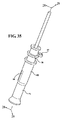
エンドエフェクタ12は、例えば、図3−図5に示されるように構成されている。エンドエフェクタ12は外科用器具14を備えている。マニピュレータ10は、外科用器具14を患者16に適用するように移動する構成になっている。具体的には、マニピュレータ10は、外科用器具14が患者に意図された医療/外科用手術の処置を行なうように外科用器具14を位置決めかつ配向するように、移動する構成になっている。
The
ロボットシステム11は、外科用ナビゲーションシステム18と連動して用いられるようになっている。外科用ナビゲーションシステム18は、エンドエフェクタ12及び患者16の位置を監視するように構成されている。この監視に基づいて、外科用ナビゲーションシステム18は、外科用器具14が適用される患者の部位に対する外科用器具14の位置を決定することになる。
The robot system 11 is used in conjunction with the surgical navigation system 18. Surgical navigation system 18 is configured to monitor the position of
図1及び図2をさらに参照すると、ロボットシステム11は可動カート20を備えている。マニピュレータ10は、エンドエフェクタ12をカート20に移動可能に接続する連結アセンブリ22を備えている。具体的には、エンドエフェクタ12は、連結アセンブリ22に接続された取付具36を備えている。
With further reference to FIGS. 1 and 2, the robot system 11 includes a
連結アセンブリ22は、例えば、第1の平行4本バーのリンクアセンブリ24及び第2の4本バーのリンクアセンブリ26を備えている。各リンクアセンブリ24,26における各継手の位置は、アクチュエータ28によって設定されるようになっている。図1において、アクチュエータ26のハウジングに部番が付されている。各アクチュエータ24,26は、リンクアセンブリ24,26の各別の1つに付随して設けられている。
The
(図1に仮想ボックスとして部分的に示されている)マニピュレータ制御装置30と呼ばれるプロセッサがカート20に取り付けられている。マニピュレータ制御装置30は、アクチュエータ28にリンクアセンブリ24,26の連結を適切に設定させる制御信号を与えるようになっている。マニピュレータ制御装置30は、多数の入力信号に基づき、リンクアセンブリ24,26の連結の位置を設定する。これらの信号は、外科用ナビゲーションシステム18からの信号データを含んでいる。これらのデータは、器具14が適用される外科部位に対する器具14の位置に関する情報をもたらすことになる。
A processor called a manipulator controller 30 (partially shown as a virtual box in FIG. 1) is attached to the
マニピュレータ制御装置30は、外科用器具14に作用する力及びトルクに基づき、リンクアセンブリ24,26の連結の位置を選択的に設定する。これらの力及びトルクは、(部番が付されていない)力/トルクセンサによって測定される。マニピュレータ制御装置30を備えるマニピュレータ10の構造は、「半自律モード又は手動境界拘束モードのいずれかによって外科用器具を制御することができる外科用マニピュレータ」と題する米国仮特許出願第61/679,258号にさらに詳細に記載されている。この文献の開示内容は、参照することによって、ここに含まれるものとする。
The
ロボットシステム11は、手動モードによって操作可能となっている。ロボットシステム11が手動モードによって操作される場合、かかるロボットシステム11は、オペレータが器具14を位置決めするためにエンドエフェクタ12に与える力及びトルクに対応するようになっている。この力及びトルクに応じて、連結アセンブリ22は、オペレータによって加えられた力及びトルクに基づいて生じ得る運動を模倣して、器具14を機械的に移動させることになる。器具14が移動すると、外科用ロボットシステム11及び外科用ナビゲーションシステム18は、協働し、かかる器具が画定された境界内にあるかどうかを決定する。この境界は、患者の体内にあり、ナビゲーションシステム18は、器具14が画定された境界の外側において作動しないように構成されている。このデータに基づき、ロボットシステム11は、連結アセンブリ22、従って、器具14の運動を選択的に制限する。具体的には、連結アセンブリ22は、画定された境界の外側において器具14の作用をもたらす器具14の運動を拘束することになる。もしもオペレータが画定された境界を越える器具14の前進をもたらす力及びトルクを加えたならば、連結アセンブリ22は、器具14のこの意図された位置決めを模倣しないことになる。
The robot system 11 can be operated in the manual mode. When the robot system 11 is operated in the manual mode, the robot system 11 corresponds to the force and torque that the operator applies to the
ロボットシステム11は、半自律モードによっても操作可能となっている。ロボットシステム11を半自律モードによって操作するために、組織内の器具14の移動の経路が生成される。この経路のうち少なくとも基本のものが、手術処置の開始前に生成される。連結アセンブリ22は、この生成された経路に基づき、器具14を前進させることになる。器具14が半自律モードによって操作される場合、連結アセンブリは、器具14を画定された境界を超えて前進させないようになっている。
The robot system 11 can be operated also in the semi-autonomous mode. In order to operate the robot system 11 in the semi-autonomous mode, a path of movement of the
外科用器具14は、オペレータが意図された医療/外科用手術の処置を行なうように制御する器具となっている。いくつかの実施形態では、外科用器具14は、電気信号を患者に作用するエネルギーの形態に変換させる動力生成ユニットを備えている。このエネルギーは、機械的エネルギー、超音波エネルギー、熱エネルギー、RFエネルギー、EMエネルギー、又はフォトニックエネルギーであるとよい。外科用器具14が動力生成ユニットを備えている場合、エネルギーは、外科用器具14から延びるエネルギー付与装置を介して外科部位に付与されることになる。図示されている代表的な実施形態では、外科用器具14は、切断アクセサリ32と、切断アクセサリ32を駆動するように切断アクセサリ32に連結されるアクチュエータ34とを備えている。
The
[II.切断アクセサリ]
切断アクセサリ32は、エンドエフェクタ12の台に取り外し可能に係合されるようになっている。例えば、図3、図5、及び図6は、エンドエフェクタ12の台に係合された切断アクセサリ32を示しており、図4は、切断アクセサリ32を係合していないエンドエフェクタ12を示している。工具38は、患者の目標組織から組織を除去するように構成されている。図示されるように、工具38は、例えば、バー(bur、削り工具)となっている。バーの代替例として、工具38は、外科部位において材料切断及び/又は材料除去を行なうためのどのような種類の外科用工具であってもよい。
[II. Cutting accessories]
The cutting
図7−図9を参照すると、切断アクセサリ32は、工具38及び該工具38に連結されたシュラウド(shroud、覆い部材)40,140を備えている。具体的には、一実施形態に係るシュラウド40を備える切断アクセサリ32が図7−図9に示されている。代替的に、他の実施形態に係るシュラウド140を備える切断アクセサリ32が図24−図25に示されている。
7-9, the cutting
図10−図14を参照すると、工具38は、近位端44、すなわち、自由端44と遠位端46との間で工具軸Tに沿って延びるシャフト42と、該シャフト42の遠位端46に固定された端片48とを備えている。シュラウド40,140は、シャフト42に回転可能に連結されるようになっている。工具38は、典型的には、50mm−200mmの長さを有している。例えば、工具38は、160mmの長さを有することができる。工具38のシャフト42は、典型的には、2.5mm−6.0mmの直径を有している。例えば、シャフト42は、4mmの直径を有することができる。
Referring to FIGS. 10-14, the
工具38は、患者16の目標組織を切断するように構成される切断チップ50を備えている。具体的には、端片48が切断チップ50を有している。
The
端片48は、例えば、シャフト42の遠位端46を受け入れる空洞52を画定している。端片48は、どのような方法、例えば、摩擦嵌合、接着、スナップリング要素、溶接等によって、シャフト42に固定されてもよい。代替的に、例えば、端片48は、シャフト42と一体に形成されてもよい。すなわち、端片48及びシャフト42は、一体部品として一緒に形成されてもよい。
The
端片48は、工具38に隣接してネジ部54を画定している。ネジ部54は、エンドエフェクタ12の端部と一緒に、破片、例えば、切除組織、体液、及び/又は灌注液をエンドエフェクタ12から離れる側に押し出すためのアルキメディアンスクリューを作るものである。
図示されている工具38は、前述したように、バーとなっており、該バーの切断チップ50は切断ヘッド72となっている。切断ヘッド72は、本発明の本質から逸脱することなく、どのような大きさ、形状、及び形態を有していてもよい。
The
シュラウド40,140は、工具38に回転可能に係合され、かつ工具軸Tに沿って工具38に対して軸方向に固定されている。シュラウド40は、工具軸Tを中心として回転可能になっている。
The
図8及び図9を参照すると、軸受56が、工具38とシュラウド40,140との間に配置され、かつ工具軸Tに沿って工具38及びシュラウド40,140に固定されている。具体的には、軸受56は孔58を画定している。軸受56は、孔58内にシャフト42を受け入れ、かつ摩擦嵌合によってシャフト42に接続されるようになっている。すなわち、孔58の内径及びシャフト42の外径は、軸受56の内径とシャフト42の外径との間における摩擦嵌合によって軸受56がシャフト42に固定されるように、寸法決めされ、かつ形作られている。摩擦嵌合は、典型的には、軸受56をシャフト42の周囲に押し込むことによって達成される。シュラウド40,140は、軸受56を受け入れ、かつ摩擦嵌合によって軸受56に接続されるようになっている。具体的には、シュラウド40,140は内面60を画定しており、軸受56の外径は内面60に摩擦嵌合されることになる。
Referring to FIGS. 8 and 9, the
図15及び図16を参照すると、シュラウド40は略円筒状になっている。シュラウド40は、内面60を有する本体部62、すなわち、基部62を備えている。少なくとも1つの指状要素(finger、フィンガー要素)64が、本体部62から延びている。図示されているシュラウド40は、例えば、本体部62から延びる7つの指状要素64を備えている。指状要素64は、工具軸Tを中心として周方向にて互いに離れている。指状要素64は、それぞれ、工具軸Tに向かってテーパを付した、すなわち、内方に傾斜したチップ66を備えている。指状要素64は、以下にさらに説明するように、本体部62に対して柔軟性(可撓性)を有している。
Referring to FIGS. 15 and 16, the
図24及び図25を参照すると、シュラウド140は、内面160及び該内面160に沿った溝161を有している。溝161は、典型的には、内面160に周方向に延びている。
Referring to FIGS. 24 and 25, the
図32−図38を参照すると、切断アクセサリ32はガード部材(保護具)68を備えている。切断アクセサリ32がハンドル300によって保持されている間に及び/又は切断アクセサリ32がエンドエフェクタ12に取り付けられているが使用されていない際に、ガード部材68は切断チップ50を覆っている。以下にさらに説明するように、ガード部材68は、マニピュレータ制御装置30に対して切断アクセサリ32のパラメータを識別可能とするような識別用構成要素、例えば、メモリチップ又はRFIDチップを保持する構成となっている。また、以下に説明するように、ガード部材68は、エンドエフェクタ12に対する切断アクセサリ32の係合及び離脱を促すように構成されていてもよい。
Referring to FIGS. 32 to 38, the cutting
切断アクセサリ32は、切断中に液体を受け入れ、かつ該液体を外科部位に送達するように構成されている。液体は、典型的には、工具38、例えば、シャフト42及び端片48を通って、外科部位に流れるようになっている。液体は、いくつかの機能を果たすことができる。例えば、液体は、切断チップを冷却し、及び/若しくは外科部位を冷却及び灌注することができ、切断チップ50と切断チップ50に接触する組織との間の界面を潤滑し、該界面における熱生成を抑えることができ、切除組織及び/若しくは体液を取り除くことができ、並びに/又は工具38のシャフト42を冷却し、先端チューブ(ノーズチューブ)100内の軸受104から熱を取り除くことができる。液体は、例えば、生理食塩水のような灌注液となっている。代替的に、液体は、本発明の本質から逸脱することなく、外科部位における外科用切断アクセサリ32及び/又は組織を冷却及び/又は灌注するどのような種類のものであってもよい。
Cutting
図7及び図8を参照すると、工具38のシャフト42は、液体を移送するように工具軸Tに沿って延びる孔70を画定している。液体は、以下にさらに説明するように、工具38の近位端44において孔70から送達され、近位端44から遠位端46に流れるようになっている。
7 and 8, the
図9−図14を参照すると、切断ヘッド72は、シャフト42の孔70と連通する少なくとも1つのポート74を画定している。切断ヘッド72は、典型的には、シャフト42の孔70とポート74との間に空洞52を画定している。ポート74は、流体をシャフト42の孔70から外科部位に送達するように切断ヘッド72を貫通している。ポート74は、手術室内のスタッフに流体の飛沫が掛かることなく流体を外科部位に送達するように設計された角度で、工具軸Tに対して延びている。また、ポート74は、流体によって外科部位に生じるキャビテーションを防ぐために、流体が外科部位に対して略直角にならない角度で、工具軸Tに対して延びている。例えば、ポート74は、典型的には、0°から45°の間の角度で工具軸Tに対して延びている。ポート74は、典型的には、0.25mmから0.50mmの直径を有している。
Referring to FIGS. 9-14, the cutting
[III.エンドエフェクタ]
図17−図31を参照すると、エンドエフェクタ12は、切断アクセサリ32がエンドエフェクタ12に係合された際に切断アクセサリ32を支持する先端チューブ100を備えている。先端チューブ100は、先端チューブ孔102を画定しており、かつ先端チューブ孔102内に切断アクセサリ32のシャフト42を受け入れるようになっている。先端チューブ100は、先端チューブ孔102内において切断アクセサリ32に離脱可能に係合し、かつ切断アクセサリ32を回転可能に支持するようになっている。典型的には、例えば、図5、図6、及び図20に示される少なくとも1つの軸受104が、先端チューブ孔102内に配置されている。軸受104は、先端チューブ孔102内にシャフト42を受け入れ、かつシャフト42を回転可能に支持するように構成されている。
[III. End effector]
With reference to FIGS. 17-31, the
先端チューブ100は取付具36に対して固定されている。先端チューブ100は、先端チューブ軸Nに沿った遠位端106、すなわち、終端106と先端チューブ100の近位端108との間で先端チューブ軸Nに沿って延びている。図示されている先端チューブ100は、先端チューブ軸Nに沿って配置された複数のセグメントを備えており、これらのセグメントは互いに固定されている。代替的に、先端チューブ100は、本発明の本質から逸脱することなく、単一片から形成されていてもよいし、又は任意の数のセグメントから形成されていてもよい。
The
エンドエフェクタ12は、切断アクセサリ32をエンドエフェクタ12に軸方向に係合するように構成される軸方向接続体110,150と、切断アクセサリ32をエンドエフェクタ12に回転可能に係合するように構成される駆動接続体112とを備えている。具体的には、一実施形態に係る軸方向接続体110は、図19−図23に示されており、他の実施形態に係る軸方向接続体150は、図24−図31に示されている。図19−図23の軸方向接続体110は、シュラウド40を備える切断アクセサリ32の実施形態に離脱可能に係合するように構成されている。図24−図31の軸方向接続体150は、シュラウド140を備える切断アクセサリ32の実施形態に離脱可能に係合するように構成されている。
The
軸方向接続体110,150は、先端チューブ軸Nに沿って終端106と駆動接続体112との間に配置されている。軸方向接続体110,150及び駆動接続体112は、先端チューブ軸Nを中心として配置されている。
The
以下にさらに説明するように、軸方向接続体110,150は、先端チューブ100によって支持され、かつ先端チューブ軸Nに沿って切断アクセサリ32を先端チューブ100に対して係止するように構成されている。また、以下にさらに説明するように、駆動接続体112は、切断アクセサリ32を先端チューブ軸Nに沿って受け入れ、かつ切断アクセサリ32を回転可能に駆動するように構成されている。
As described further below, the
典型的には、軸方向接続体110,150及び駆動接続体112は、先端チューブ軸Nに沿って互いに離れている。例えば、軸方向接続体110,150は、先端チューブ100の遠位端106に配置されており、駆動接続体112は、先端チューブ100の遠位端106と近位端108との間で先端チューブ軸Nに沿って軸方向接続体110,150から離れている。代替的に、駆動接続体112及び軸方向接続体110,150は、工具軸Tに沿って互いに隣接して配置されてもよい。軸方向接続体110、150及び遠位接続体は、切断アクセサリ32をエンドエフェクタ12に離脱可能に係合させるようになっている。
Typically, the
軸方向接続体110,150は、先端チューブ100によって支持され、かつ切断アクセサリ32を先端チューブ軸Nに沿って先端チューブ100に離脱可能に係止するようになっている。軸方向接続体110,150は、切断アクセサリ32のシュラウド40に離脱可能に係合するようになっている。軸方向接続体110,150は、先端チューブ軸Nに沿って延びると共に切断アクセサリ32を受け入れる孔57を画定している。切断アクセサリ32は、先端チューブ100の終端106から軸方向接続体110,150を通って駆動接続体112に延びることになる。切断アクセサリ32が先端チューブ100に組み込まれると、切断アクセサリ32のシュラウド40は、切断チップ50、例えば、図示されているバーに近位の第1の端47及びバーから遠位の第2の端49間で、先端チューブ軸Nに沿って延びることになる。シャフト42は、シュラウド40の遠位端49から駆動接続体112に延びることになる。
The
図19−図21に示される軸方向接続体110を参照すると、軸方向接続体110は、典型的には、先端チューブ100の遠位端106に連結され、拡張位置、すなわち、図19及び図20に示されるような切断アクセサリ32を保持する係止位置と、後退位置、すなわち、図21に示されるような切断アクセサリ32を解放する離脱位置との間で、先端チューブ10に対して移動可能になっている。具体的には、軸方向接続体110,150は、係止位置と離脱位置との間で軸に沿って移動可能になっている。
Referring to the
軸方向接続体110は、例えば、先端チューブ100に摺動可能に保持される筒状要素(バレル要素)114、すなわち、リング要素114を備えている。換言すれば、筒状要素114は、先端チューブ100に保持され、かつ拡張位置と後退位置との間で先端チューブ100に対して摺動可能になっている。典型的には、筒状要素114は、工具軸Tを中心として回転可能になっている。筒状要素114は、典型的には、円筒状であり、かつ先端チューブ100を受け入れるようになっている。
The
切断アクセサリ32が先端チューブ100に係合し、軸方向接続体110が係止位置にある際に、筒状要素114は、シュラウド40の周りに半径方向に延出し、かつシュラウドを先端チューブ100に対して挟み込むようになっている。換言すれば、拡張位置において、筒状要素114は、切断アクセサリ32、例えば、切断アクセセリ32のシュラウド40に係合し、これによって、切断アクセサリ32を先端チューブ100に係合させることになる。後退位置では、筒状要素114は、切断アクセサリ32から離脱され、これによって、切断アクセサリ32を先端チューブ100から解放することになる。
When the cutting
図18−図23を参照すると、先端チューブ100は、軸方向接続体110を支持するガイド部116を備えている。例えば、先端チューブ100は、ガイド部116を成すガイド部分118を備えている。筒状要素114及びガイド部116は、筒状要素114が拡張位置と後退位置との間でガイド部116に沿って移動可能となるように筒状要素114をガイド部116に操作可能に連結する係合用特徴部を画定している。
Referring to FIGS. 18 to 23, the
例えば、図19−図23に示されているように、少なくとも1つの係合部材120が、筒状要素114及びガイド部116に係合され、筒状要素114及びガイド部116を互いに連結している。先端チューブ100のガイド部116は、少なくとも1つの通路122を画定しており、係合部材120は、拡張位置と後退位置との間で通路122に沿って移動可能に係合されている。通路122は、先端チューブ軸Nに沿って長手方向に延びており、典型的には、ガイド部116を貫通している。図示されている先端チューブ100は、4つの通路122にそれぞれ係合された4つの係合部材を備えている。しかし、軸方向接続体110は、どのような数の係合部材120及び対応する通路122を備えていてもよい。
For example, as shown in FIGS. 19 to 23, at least one engaging
係合部材120は、例えば、筒状要素114をガイド部分118に連結するように筒状要素114に係合されると共にガイド部116の通路に係合される球面状のボール要素となっている。筒状要素114は、典型的には、半球面状のボール要素を受け入れる凹部124を画定している。ボール要素は、凹部124内において回転可能になっており、かつ工具軸Tに沿って筒状要素114に固定されている。ボール要素は、通路に沿って、すなわち、先端チューブ軸Nに沿って筒状要素114の移動を案内するように、ガイド部116の通路122に係合されている。ボール要素の代替例として、係合部材120は、筒状要素114をガイド部分に連結するどのような種類の構成要素、例えば、ピン、フランジ等であってもよい。
The engaging
図19−図22を参照すると、軸方向接続体110は、筒状要素114に連結された付勢機構126、例えば、バネ126を備えている。付勢機構126は、筒状要素114を拡張位置に向かって付勢するように構成されている。筒状要素114は、付勢機構126によって与えられた力を上回るのに十分な力、すなわち、付勢機構126を圧縮するのに十分な力を筒状要素114に対して後退位置に向かって加えることによって、後退位置に移動することができる。図示されているように、例えば、付勢機構126は、先端チューブ孔102内に配置されている。付勢機構126は、図19−図21に示されるように、先端チューブ孔102内において軸受104に当接し、これによって、先端チューブ軸Nに沿って適所に保持されている。図示されている付勢機構126は、コイルバネとなっている。代替的に、付勢機構126は、どのような種類の付勢機構であってもよい。
Referring to FIGS. 19 to 22, the
図19−図22をさらに参照すると、付勢機構126及び筒状要素114を連結させるように、プランジャー128が付勢機構126と筒状要素114との間に配置されている。具体的には、プランジャー128は、先端チューブ孔102内に配置されており、かつ先端チューブ孔102内において先端チューブ100に対して摺動するように構成されている。係合部材120、例えば、ボール要素は、プランジャー128と筒状要素114との間に配置され、係合部材120は、プランジャー128に接触するようになっている。プランジャー128は、係合部材120を受け入れるテーパ面130を画定している。付勢機構126は、軸受56とプランジャー128との間でプランジャー128に当接することになる。プランジャー128の代替例として、筒状要素114及び付勢機構126は、互いに直接接触するように構成されてもよい。
With further reference to FIGS. 19-22, a
図19−図22をさらに参照すると、先端チューブ100は、先端チューブ100の遠位端106の近くに、溝132、すなわち、凹部132を画定している。溝132は、先端チューブ1002の周方向に延びている。図19−図21を参照すると、溝132は、先端チューブ軸Nから離れる側にテーパを付した傾斜面134によって部分的に画定されている。勾配面136が、傾斜面134から先端チューブ100の遠位端に向かって延び、先端チューブ軸Nに向かってテーパが付されている。拡張位置にある際、筒状要素114は、典型的には、溝132に隣接して配置され、すなわち、先端チューブ軸Nに沿って溝132と少なくとも部分的に真っ直ぐに並んで溝132の少なくとも一部の周りに半径方向に配置されることになる。
With further reference to FIGS. 19-22, the
軸方向接続体110を用いることによって、工具38を用いることなく、すなわち、単にオペレータの手によって、切断アクセサリ32をエンドエフェクタ12に係合させることができる。エンドエフェクタ12への切断工具38の組み込みを片手操作によって、すなわち、オペレータの片方の手によって行なうことができる。切断工具38は、切断工具38を先端チューブ孔102内に挿入し、切断工具38に先端チューブ孔102に沿って先端チューブ100に向かう圧力を加え、その結果、切断工具38を軸方向接続体110に係合させることによって、エンドエフェクタ12に組み込まれることになる。
By using the
具体的には、切断アクセサリ32をエンドエフェクタ12に組み込むために、工具38のシャフト42が先端チューブ孔102内に挿入される。シャフト42が先端チューブ孔102に沿って移動すると、かかるシャフト42は、先端チューブ孔102内の軸受104に嵌入される。前述したように、シュラウド40の指状要素64は、シュラウド40の本体部62に対して柔軟性を有している。典型的には、シュラウド40が筒状要素114に接近すると、指状要素64は、勾配面136に沿って摺動し、かつ勾配面136に沿って工具軸Tに対して外方に変形する。
Specifically, the
シャフトが先端チューブ孔102に沿って移動すると、指状要素64のチップ66が筒状要素114に当接し、筒状要素114を後退位置に向かって押圧する。具体的には、指状要素64及び筒状要素114は、切断アクセサリ32が先端チューブ100に係合する際に先端チューブ軸Nに沿って互いに向き合った対向面115を備えている。対向面115は、典型的には、傾斜している。例えば、各指状要素64の対向面115は、先端チューブ100に対する切断アクセサリの係合中に先端チューブ100に接触して指状要素64を撓ませるように、シュラウド40の第1の端47からシュラウド40の第2の端49に向かう方向において半径方向内方にテーパが付された斜面となっている。各指状要素64の対向面115は、シュラウド40の第2の端で終端している。
When the shaft moves along the
指状要素64のチップ66が溝132に接近すると、チップ66は、工具軸Tに向かって内方に移動して先端チューブ100の溝132内に入り、筒状要素114は、拡張位置に戻って切断アクセサリ32を先端チューブ100に係止することになる。換言すれば、切断アクセサリ32が先端チューブ100に係合して軸方向接続体110が拡張位置にある際に、軸方向接続体110は指状要素64に係合することになる。
When the
指状要素64は、それぞれ、図15及び図16に示されているように、例えば、溝132に係合するように構成された突起65を画定している。指状要素64は、典型的には、指状要素64が予め変形された形状に向かってバネ付勢されて溝132内に入るように、勾配面136に沿って外方に弾性変形する構成となっている。付加的又は代替的に、筒状要素114は、チップ66が筒状要素114に接触して筒状要素114に沿って摺動すると、指状要素64を溝132内に変形させるようになっていてもよい。
The finger-
切断アクセサリ32がエンドエフェクタ12に係合すると、切断アクセサリ32の軸受56は先端チューブ100の遠位端106に当接する。軸方向接続体110は、切断アクセサリ32の軸受56が先端チューブ100の遠位端106に当接した際に、切断アクセサリ32に係合するように構成されている。指状要素64のチップ66を溝132内にスナップ嵌合させることによって、切断アクセサリ32が軸方向接続体110に対して適所に配置されて先端チューブ100に係合されたこと、すなわち、軸受56が先端チューブ100の遠位端106に当接したことを触覚によって確認することができる。換言すれば、オペレータが、指状要素64のチップ66が溝132内に入ったことを感触、視覚、及び/又は聴覚によって知った際に、オペレータは、切断アクセサリ32がエンドエフェクタ12に対して適切に配置され、かつ軸方向接続体110に係合したことを確認することができる。指状要素64、先端チューブ100の勾配面136、及び筒状要素114は、切断アクセサリ102がエンドエフェクタ12に係合した際、すなわち、指状要素64のチップ66が先端チューブ100の勾配面136と筒状要素114との間に係合した際、先端チューブ100の遠位端106に対して軸受56を引き込むように構成されている。
When the cutting
指状要素64のチップ66が溝132内にある際に、付勢機構126は、過剰な力が筒状要素114に付与されない限り、筒状要素114を拡張位置に付勢する。指状要素64のチップ66が溝132内にあり、筒状要素114が拡張位置にある際に、筒状要素114は、指状要素64を先端チューブ100の傾斜面134に対して挟み込み、かつシュラウド40を先端チューブ100に係止している。
When the
切断工具38をエンドエフェクタ12から解放させるように、筒状要素114が後退位置に移動し、これによって、指状要素64のチップ66が溝132から離脱する。典型的には、オペレータが後退位置に向かう力を筒状要素114に加えることによって、筒状要素114が後退位置に移動することになる。筒状要素114及び先端チューブ100は、筒状要素114が後退位置に移動する際に互いに当接するように構成された対向面138を画定している。
The
筒状要素114が後退位置にある際、切断工具38は、先端チューブ軸Nに沿って先端チューブ100から離れる側に移動可能である。典型的には、指状要素64は、筒状要素114が後退位置にある際、溝132内に位置するように構成されており、切断工具38が先端チューブ100から離れる側に移動すると、指状要素64のチップ66が傾斜面134に沿って摺動し、指状要素64は、工具軸Tから離れる方に弾性的に変形することになる。
When the
前述したように、ガード部材68は、エンドエフェクタ12に対して切断アクセサリ32を係合及び離脱させるように構成されている。具体的には、ガード部材68は、筒状要素114を作動させるように構成されている。換言すれば、ガード部材68は、筒状要素114を後退位置に移動させ、かつ先端チューブ100に対して切断アクセサリ32を係合及び離脱させるように構成されている。
As described above, the guard member 68 is configured to engage and disengage the cutting
図32−図34Bを参照すると、ガード部材68は、外側部材76及び外側部材76に摺動可能に係合された内側部材78を備えている。具体的には、外側部材76は、孔80を画定しており、かつ内側部材78を孔80内に摺動可能に受け入れるようになっている。内側部材78は、孔80内において、図37に示されるような拡張位置と図38に示されるような圧縮位置との間で摺動可能になっている。
Referring to FIGS. 32-34B, the guard member 68 includes an
図34Aを参照すると、外側部材76は、本体82及び該本体82に柔軟に接続された柔軟中子84を備えている。柔軟中子84は、孔80内に延びる掛かり部86を保持している。内側部材78は、掛かり部86を受け入れる長孔88を画定している。
Referring to FIG. 34A, the
図34Bを参照すると、内側部材78は、本体90及び該本体90に柔軟に接続された柔軟中子92を備えている。柔軟中子92は掛かり部90を保持している。内側部材78は、例えば、切頭円錐状の内側棚94を画定している。内側部材78はフィンガーグリップ97を備えることができる。
Referring to FIG. 34B, the
図35及び図36を参照すると、ガード部材68は、切断アクセサリ32を受け入れている。前述したように、ガード部材68は、切断アクセサリ32の操作を促すように切断アクセサリ32の切断チップ50を覆っている。
Referring to FIGS. 35 and 36, the guard member 68 receives the cutting
切断アクセサリ32がガード部材68内に配置されると、切断アクセサリ32のシュラウド40が棚94に当接する。シュラウド40は、内側部材78の中子92を受け入れる溝96を画定している。
When the cutting
シュラウド40が棚94に当接するようにガード部材68が切断アクセサリ32を受け入れた際に、オペレータは、内側部材78を用いて、切断アクセサリ32を軸方向接続体110に係合させることができる。具体的には、切断アクセサリ32のシャフト42が先端チューブ孔102内にある状態において、ユーザーは、先端チューブ軸Tに沿って先端チューブ100に向かって内側部材78に力を加え、これによって、ガード部材68の棚94がシュラウド40を軸方向接続体110に係合させる。一旦、シュラウド40が軸方向接続体100と係合したならば、ガード部材68に先端チューブ軸Tに沿って先端チューブ100から離れる側に力を加えることによって、ガード部材68を切断アクセサリ32から取り外すことができる。
When the guard member 68 receives the cutting
例えば、外科手術の処置後、切断アクセサリ32を軸方向接続体110から離脱させるように、ガード部材68が、棚94をシュラウド40に当接させて切断アクセサリ32上に配置される。このような配置によって、外側部材76の中子84が、筒状要素114の溝98に係合する。次いで、図38に示されるように、外側部材76が内側部材78に対して圧縮位置に移動され、これによって、筒状要素114が後退位置に移動することになる。
For example, the guard member 68 is placed on the cutting
具体的には、オペレータは、内側部材78を片手で掴み、外側部材76を他の手で掴む。次いで、オペレータは、外側部材76を内側部材78に対して先端チューブ軸Nに沿って移動させる。図38に示されるように、この移動によって、外側部材76の中子84を筒状要素114の溝98に対して押し込み、これによって、筒状要素114を後退位置に移動させ、切断アクセサリ32を先端チューブ100から離脱させることになる。
Specifically, the operator holds the
前述したように、ガード部材68が切断アクセサリ32に配置された際、内側部材78の中子92は、シュラウド40に摩擦によって係合される。外側部材76が圧縮位置に移動した時点で、図38に示さるように、外側部材76及び内側部材78は、先端チューブ軸Nに沿って先端チューブ100から離れる側に移動し、これによって、切断アクセサリ32を先端チューブ100から取り外すことができる。この運動中、中子92とシュラウド40との間の摩擦係合によって、ガード部材68が先端チューブ100から離れる側に移動する際に切断アクセサリ32をガード部材68に取り付けた状態で保持することができる。
As described above, the
前述したように、図24−図31に示されている軸方向接続体150は、シュラウド140を備える切断アクセサリ32を受け入れるようになっている。軸方向接続体150は、先端チューブ100のガイド部152に支持されている。軸方向接続体150は、ガイド部152によって支持される指状要素154と、筒状要素156とを備えている。筒状要素156は、以下にさらに説明するように、指状要素154をガイド部152に対して半径方向に係止及び離脱させるように、先端チューブ軸Tを中心として回転可能になっている。
As previously described, the
具体的には、図26及び図27を参照すると、軸方向接続体150は、リング要素162及び該リング要素162から延びる指状要素154を有する係止部材153を備えている。指状要素154は、それぞれ、突起164を備えている。図26及び図27は、2つの指状要素154を備える係止部材153を示しているが、係止部材153は、本発明の本質から逸脱することなく、どのような適切な数の指状要素154を備えていてもよい。
Specifically, referring to FIGS. 26 and 27, the
図26、図28、及び図29を参照すると、ガイド部152は、係止カラー158を受け入れている。ガイド部152は、図26及び図27に示されているように、一対の長孔166を画定しており、指状要素154のそれぞれの突起164が、図27及び図28に示されるように、それぞれ、長孔166を貫通するように位置決めされている。指状要素154は、長孔166を貫通するように突起164を付勢している。
Referring to FIGS. 26, 28, and 29, the
図26−図29を参照すると、係止カラー158は、ガイド部152内に配置され、かつ指状要素154の半径方向内方に位置決めされている。係止カラー158は、典型的には、円筒状の壁168を備えている。壁168は、以下にさらに説明するように、指状要素154の突起164を受け入れるように壁168の周りに互いに周方向に離れて配置された切欠き170を画定している。
Referring to FIGS. 26-29, the
筒状要素156は、ガイド部152上に支持され、かつガイド部152を通して係止カラー158に係合している。具体的には、図29に最もよく示されるように、ボール要素172が、ガイド部152の長孔174を貫通し、かつ筒状要素156及び係止カラー158に係合している。図26、図27、及び図29に最もよく示されているように、筒状要素156は、ボール要素172を受け入れる凹み176を画定している。図26及び図27を参照すると、係止カラー158は、ボール要素172を受け入れる溝178を画定している。図27及び図28は、2つのボール要素172を示しているが、係止カラー158は、本発明の本質から逸脱することなく、どのような適切な数のボール要素172を備えていてもよい。
The
筒状要素156は、図28及び図29に示されているような離脱位置と(図示されていない)係止位置との間で、先端チューブ軸Nを中心として回転可能となっている。係止カラー158は、係止位置と離脱位置との間で筒状要素156と一緒に移動する。離脱位置では、筒状要素156は、係止カラー158の切欠き170を指状要素154と真っ直ぐに並べるように位置決めされ、これによって、指状要素154は、突起164に作用する力に応じて半径方向内方に弾性的に移動することになる。係止位置では、筒状要素156は、係止カラー158の壁168を指状要素154と真っ直ぐに並べるように位置決めされる。このような位置では、壁168は、突起164に作用する力に応じて、半径方向内方への指状要素154の移動を防ぎ、すなわち、指状要素154を適所に係止させることになる。
The
図30及び図31を参照すると、切断アクセサリ32は、切断アクセサリ32のシャフト38を先端チューブ軸Nに沿って先端チューブ孔102内に挿入することによって、先端チューブ100に取り付けられる。筒状要素156が離脱位置にある状態において、すなわち、係止カラー158の切欠き170が指状要素154と真っ直ぐに並んだ状態において、切断アクセサリ32のシュラウド110が突起164に達すると、かかるシュラウド140が指状要素154の突起164を半径方向内方に押し込むことになる。シュラウド140が指状要素154を半径方向内方に押し込むことによって、切断アクセサリ32は、図30及び図31に示されるように、先端チューブ100に対して着座することができる。具体的には、切断アクセサリ32が先端チューブ100に対して着座した際、切断アクセサリ32の軸受56が、先端チューブ100の遠位端106に当接することになる。
Referring to FIGS. 30 and 31, the cutting
切断アクセサリ32が先端チューブ100に対して着座すると、指状要素154は、例えば、図30及び図31に示されるように、ガイド部152の長孔166内に弾性的に付勢され、かつシュラウド140の溝178と係合することになる。切断アクセサリ32が先端チューブ100に対して着座した際、筒状要素156は、係止位置に、すなわち、係止カラー158の壁168を指状要素154と真っ直ぐに並べ、半径方向内方への指状要素154の押込みを防ぐ位置に回転する。このような位置では、軸方向接続体150は、切断アクセサリ32を先端チューブに対して軸方向に係止している。
When the cutting
切断アクセサリ32を先端チューブ100から分解する際、筒状要素156は、離脱位置に、すなわち、係止カラー158の切欠き170を指状要素154と真っ直ぐに並べる位置に回転する。このような位置では、切断アクセサリ32を先端チューブ100から引っ張ると、切断アクセサリ32のシュラウド140が、指状要素154を切欠き170内に半径方向内方に押し込み、これによって、切断アクセサリ32を先端チューブ100から取り外すことが可能になる。
When disassembling the cutting
図26を参照すると、ガイド部152及び係止カラー158は、筒状要素156の係止位置及び離脱位置を触覚フィードバックによって識別するように構成されている。具体的には、ガイド部152の長孔174は戻り止め180を画定しており、係止カラー158の溝178は、浅い部分182及び深い部分184を有している。平坦部186が、長孔174の戻り止め180間に位置している。バネ188が、ガイド部152内においてガイド部152と係止カラー158との間に配置されており、かつボール要素172を戻り止め180及び浅い部分182内に付勢している。
Referring to FIG. 26, the
具体的には、筒状要素156が離脱位置にある際、ボール要素172は戻り止め180の1つに配置されている。筒状要素156が係止位置に向かって回転されると、平坦部186が、係止カラー158をバネ188に対して押し付ける。ボール要素172が他の戻り止め180に達すると、バネがボール要素172を他の戻り止め180内に押し込むことになる。ボール要素172と戻り止め180との相互作用によって、触覚フィードバックが得られると共に、選択された離脱位置又は係止位置に筒状要素156を弾性的に保持することが可能になる。
Specifically, the
図39及び図40を参照すると、切断工具38は、切断アクセサリ32を駆動するように構成される駆動システム200を備えている。図示される駆動システム200は、切断アクセサリ32に回転運動を与えるように、例えば、バーを回転させるように構成されている。代替的に、駆動システム200は、切断アクセサリ32にどのような種類の運動、例えば、往復鋸用の直線振動、対向ブレードのための挟込み運動、ニードル/カテーテルのための直線運動等を与えるように構成されていてもよい。
With reference to FIGS. 39 and 40, the cutting
駆動システム200は、先端チューブ100によって支持された駆動部材202、例えば、回転駆動部材202と、駆動部材202に連結されたアクチュエータ34と、切断アクセサリ32に回転可能に係合するように駆動部材202に連結された駆動接続体112とを備えている。図示されている駆動部材202は、先端チューブ100内に回転可能に支持されている。具体的には、軸受204が駆動部材202と先端チューブ100との間に配置され、軸受204は、駆動部材202を先端チューブ100内に回転可能に支持している。図44及び図45を参照すると、駆動部材202は、軸受204を受け入れる軸受面234を画定している。以下にさらに説明するように、駆動部材202を回転させるように、アクチュエータ34が駆動部材に連結されている。具体的には、アクチュエータ34は、駆動接続体112に連結され、かつ駆動接続体112を先端チューブ100に対して回転させるようになっている。
The
駆動接続体112は、先端チューブ100によって支持され、かつ切断アクセサリ32を回転可能に駆動するように切断アクセサリ32を受け入れる構成になっている。駆動接続体112は、先端チューブ軸Nに沿って延びて切断アクセサリ32を受け入れる孔207を画定している。
The
図41−図43を参照すると、駆動接続体112は、楔スリーブ208及び該楔スリーブ208内に配置されたクラッチアセンブリ210を備えている。軸方向接続体110は、クラッチアセンブリ210から離れている。具体的には、軸方向接続体110は、クラッチアセンブリ210と切断アクセサリ32の切断チップ50との間に配置されている。
With reference to FIGS. 41-43, the
クラッチアセンブリ210は、工具38のシャフト42を先端チューブ軸Nに沿って摺動可能に受け入れるように構成されている。クラッチアセンブリ210は、駆動部材202によって支持され、かつ駆動部材202に対して回転可能になっており、さらには、シャフト42を駆動部材202に選択的に係止するように、先端チューブ軸Nに沿って切断アクセサリ32のシャフト42を受け入れる構成になっている。具体的には、シャフト42は、工具38をクラッチアセンブリ210に係合させるようにクラッチアセンブリ210内に摺動可能になっており、かつ工具38をクラッチアセンブリ210から離脱させるようにクラッチアセンブリ210から外方に摺動可能になっている。
The
楔スリーブ208及びクラッチアセンブリ210は、駆動部材202から切断アクセサリ32のシャフト42に回転を伝達させるために、駆動部材202をシャフト42に摩擦によって係止するように構成されている。クラッチアセンブリ210によって、切断アクセサリ32への比較的短いシャフト42の使用が可能になる。切断アクセサリ32の比較的短いシャフト42のこのような使用は、切断アクセサリ32の剛性を高め、外科的アクセスを向上し、少ない材料の使用に起因してより経済的となっている。
The
図48−図55を参照すると、クラッチアセンブリ210は籠状要素212を備えている。籠状要素212は、孔と、該孔に連通するように籠状要素212を中心として周方向に互いに離れた複数の長孔216とを画定している。ローラ要素214が、長孔216のそれぞれに配置されている。籠状要素212は、各長孔216を画定する一対の離れた縁部218を画定しており、ローラ要素214は、対の縁部218の両方に当接している。ローラ要素214は、長孔を通って孔内に延びている。ローラ要素214は、互いに離れており、かつそれらの間にシャフト42を受け入れるようになっている。
Referring to FIGS. 48-55, the
ローラ要素214は、籠状要素212に対して半径方向に移動可能になっている。バネ220が、ローラ要素214及び籠状要素212を周回し、ローラ要素214を籠状要素212の長孔218に保持し、かつローラ要素214を縁部218に接触させている。ローラ要素214は、例えば、バネ220を受け入れるように構成された首部222を画定している。図48−図55に示されているクラッチアセンブリ210は、6つの長孔218及び6つのローラ要素214を備えているが、クラッチアセンブリ210は、どのような数の長孔218及び対応するローラ要素214を備えていてもよい。切断アクセサリ32のシャフト42がクラッチアセンブリ210に配置された際、かかるシャフト42は、ローラ要素213のそれぞれに接触することになる。
The
図41−図43を参照すると、駆動部材202は、例えば、ソケット状要素226に係合し、クラッチアセンブリ210は、駆動部材202とソケット状要素226との間に保持されている。ソケット状要素226は、例えば、リップ228を画定しており、駆動部材202は、端230を備えている。リップ228及び端230は、それらの間に空洞232を画定しており、クラッチアセンブリ210は、図43に示されるように、空洞323内に配置されている。軸受206が、ソケット状要素226と先端チューブ100との間に配置されている。軸受206は、ソケット状要素226を先端チューブ100内に回転可能に支持している。図44及び図45を参照すると、ソケット状要素226は、軸受206を受け入れる軸受面236を画定している。
41-43, the
駆動接続体112は、クラッチアセンブリ210を受け入れる内壁209を備えており、かつローラ要素214をシャフト42に対して選択的に付勢するように構成されている。具体的には、楔スリーブ208が内壁209を画定している。図47に単独で示されている楔スリーブ208は、図41−図43に示されているように、駆動部材202とソケット状要素226との間に配置され、かつ駆動部材202に固定されている。楔スリーブ208は、どのような方法、例えば、圧入、溶接、接着、ピン止め等によって駆動部材202に固定されてもよい。
The
図47及び図52−図55を参照すると、楔スリーブ208は、孔238を画定しており、かつ孔238の周方向に配置された接触面240を有している。図47及び図52−図55に示されている接触面240は、切子面(facets)、すなわち、平面である。代替的に、接触円240は、楔スリーブ208がクラッチアセンブリ210に対して回転している際に、接触面240と工具38のシャフト42との間でローラ要素214を挟み込むのに十分などのような形状を有していてもよい。例えば、接触面240は、先端チューブ軸Nを中心とする円弧面であってもよい。図47及び図52−図55の楔スリーブ208は、12の接触面240を備えており、すなわち、十二角形となっている。代替的に、楔スリーブ208は、どのような数の接触面240を備えていてもよい。
47 and 52-55, the
接触面240は、楔スリーブ208がクラッチアセンブリ210に対して回転する際に、ローラ要素214に接触するように構成されている。図52及び図53に示されるように、工具38のシャフト42がクラッチアセンブリ210内に挿入される前に、ローラ要素214は接触面240から離れている。図54に示されるように、シャフト42がクラッチアセンブリ210内に最初に挿入された際に、ローラ要素214は、接触面240から離れた状態に留まっている。クラッチアセンブリ210が楔スリーブ208に対して回転すると、図55に示されるように、ローラ要素214は、工具38のシャフト42を駆動システム200に回転可能に係止することになる。
例えば、アクチュエータ34が駆動部材202を駆動すると、駆動部材202は、楔スリーブ208をクラッチアセンブリ210に対して回転させる。楔スリーブ208がクラッチアセンブリ210に対して回転すると、接触面240が、ローラ要素214に接触し、ローラ要素214を接触面240と工具38のシャフト42との間に挟み込み、工具38のシャフト42を駆動部材202に回転可能に係止することになる。換言すれば、接触面240が、ローラ要素214を工具38のシャフト42に摩擦係合させることになる。クラッチアセンブリ210は、自己係合し、かつ自己離脱するものである。オペレータは、シャフト42を先端チューブ軸Nに沿って単に挿入することによって、シャフト42をクラッチアセンブリ210に係合させることができる。すなわち、オペレータは、捻れを生じさせることなく、シャフト42をクラッチアセンブリ210に係合させることができる。前述したように、軸方向接続体110は、切断アクセサリ32を先端チューブ100に対して先端チューブ軸Nに沿って軸方向に保持した状態を保っている。
For example, when the
クラッチアセンブリ210は、工具38のシャフト42の円筒外面43に離脱可能に係合するように構成されている。具体的には、シャフト42は、駆動接続体112に離脱可能に係合する円筒断面を有する外面43を含んでいる。外面43は、典型的には、シュラウド40から自由端45に延びる一定外径を有している。換言すれば、クラッチアセンブリ210は、工具38のシャフト42が該シャフト42に回転運動を伝達するように設計された平坦部又は他の特徴部を有することを必要としない。クラッチアセンブリ210は、円筒状シャフト42の任意の部分に係合可能である。シャフト42は、典型的には、近位端44と遠位端46との間にわたって、すなわち、シャフト42の全長に沿って円筒状になっている。従って、シャフト42をクラッチアセンブリ210に係合させるために、シャフト42を先端チューブ軸Nに沿って特に位置合わせさせる必要がない。換言すれば、シャフト42は、シャフト42の特定の特徴部を先端チューブ軸Nに沿った特定の箇所に位置合わせさせることなく、クラッチアセンブリ210に係合することになる。
The
駆動部材202、楔スリーブ208、及びクラッチアセンブリ210を備える駆動システムによって、高い剛性を有する切断アクセサリ32の使用が可能になり、切断アクセサリ32による見通し線の干渉が少なくなり、先端チューブ100の端部における容積の縮小によって外科的視界のアクセス性が高められ、さらに、例えば、軸方向接続体110と共に用いられる際における正確な軸方向の位置決めが可能になる。
A drive system comprising a
駆動システム200、特に、駆動部材202、楔スリーブ208、及びクラッチアセンブリ210の使用は、エンドエフェクタ12に制限されるものではない。換言すると、駆動システム200は、どのような形式の装置に実施されてもよい。例えば、手動の動力工具(図示せず)が、駆動システム200を備えることができる。手動の動力工具は、例えば、外科用の手動の動力工具であってもよい。
The use of
駆動システム200は、灌注される切断アクセサリとの使用に制限されるものではない。例えば、駆動システム200は、中実の切断工具に連結して用いられてもよい。このような1つの形式の切削工具は、例えば、2mmの直径を有するシャフトを備えることができる。
The
エンドエフェクタ12及び切断アクセサリ32は、液体をエンドエフェクタ12及び切断アクセサリ32を通して外科部位に送達する液体送達経路Lを画定している。液体送達経路Lの一実施形態は、図5及び図6に示されており、液体送達経路Lの他の実施形態は、図31に示されている。駆動部材202の孔242、すなわち、管腔242、工具38の孔、及び切断ヘッド72のポートが液体送達経路Lを画定している。
図43−図45を参照すると、以下にさらに説明するように、駆動部材202は、液体を受け入れるように構成されたニップル244を備えている。駆動部材202は、工具軸Tに沿って及び駆動部材202を通ってニップル244から延びる孔242を画定している。前述したように、駆動部材202は、該駆動部材202の孔242内に切断アクセサリ32のシャフト42を受け入れ、すなわち、切断アクセサリ32に離脱可能に係合され、駆動部材202は、液体をニップル244からシャフト42に送達するようになっている。切断中、液体は、ニップル244から駆動部材202の孔242内に送達され、駆動部材202の孔242及びシャフト42の孔70を通って、切断ヘッド72のポート74から外科部位に流出することになる。
Referring to FIGS. 43-45, the
図5及び図6を参照すると、ここでは第1のシール要素とも呼ばれる静止シール部材246が駆動部材202の孔内に配置されている。静止シール部材246は、切断アクセサリ32が駆動部材202の孔内に受け入れられた際に、駆動部材202と切断アクセサリ32のシャフト42との間から液体が漏れるのを防ぐために、駆動部材202と切断アクセサリ32との間を密封するものである。
With reference to FIGS. 5 and 6, a
静止シール部材246は孔248を画定している。静止シール部材246は、工具38のシャフト42が孔248内に挿入された際に、シャフト42の外部を密封するように構成されている。図43−図45を参照すると、駆動部材202は、静止シール部材246を受け入れるポケット250を画定している。静止シール部材246は、切断アクセサリ32を先端チューブ軸Nに沿って孔248内に摺動可能に受け入れている。具体的には、駆動部材202はポケット250を画定している。静止シール部材246は、駆動部材202と切断アクセサリ32との間を密封するために、駆動部材202及び切断アクセサリ32に回転可能に固定されている。
静止シール部材246は、駆動部材202及び切断アクセサリ32のシャフト42がユニットとして一緒に移動し、また、静止シール部材246が駆動部材202と切断アクセサリ32との間を静止して密封するという点において、「静止している(static)」のである。静止シール部材246は、例えば、高温エラストマー材料、例えば、オートクレーブ適合性を有するシリコーン又はViton(登録商標)である。
The
図5−図6及び図56−図58を参照すると、エンドエフェクタ12は、キャリッジ部材(carriage)252、すなわち、流体送達部材を備えている。キャリッジ部材252は、流体を駆動部材202の孔242に送達するように駆動部材202に連結される構成となっている。キャリッジ部材252は、駆動部材202に取り外し可能に係合できるようになっている。具体的には、キャリッジ部材252は、ニップル244に取り外し可能に接続するように構成されている。キャリッジ部材252は、エンドエフェクタ12の残りの部分に液体、電気、及び/又はデータを送達するように構成されている。例えば、キャリッジ部材252がニップル244に接続されると、キャリッジ部材252は、液体を液体送達経路Lに送達するように構成される液体送達経路Lに連通することになる。
5-6 and 56-58, the
図5及び図6をさらに参照すると、ハウジング254が先端チューブ100に取り付けられている。ハウジング254は、キャリッジ部材252を取り外し可能に受け入れる空洞256を画定している。キャリッジ部材252及び空洞256は、例えば、キャリッジ部材252が摩擦嵌合によって空洞256内に保持されるように、構成されている。代替的又は付加的に、キャリッジ部材252及び空洞256は、キャリッジ部材252を空洞256内に選択的に保持するためのどのような種類の特徴部を備えていてもよい。
With further reference to FIGS. 5 and 6, a
キャリッジ部材252は、例えば、液体を駆動部材202の孔242に送達するように、駆動部材202のニップル244に係合している。キャリッジ部材252は液体供給源(図示せず)に接続されており、液体供給源は、液体をキャリッジ部材252に送達するようになっている。液体供給源は、例えば、マニピュレータ制御装置30によって制御される蠕動ポンプである。配管(図示せず)が、典型的には、キャリッジ部材252を液体供給源に接続している。
The
図56−図58を参照すると、キャリッジ部材252は、駆動部材202のニップル244に接続されると共に、ここでは第2のシール要素とも呼ばれる動的シール部材258を備えている。動的シール部材258は、ニップル244を受け入れる孔260を画定している。キャリッジ部材252が駆動部材202に連結される際、動的シール部材258は、ニップル244とキャリッジ部材252との間でニップル244の周りに配置されている。動的ソール258は、例えば、Teflon(登録商標)含浸ポリアミドである。
56-58, the
動的シール部材258は、駆動部材202とキャリッジ部材252との相対的な回転中に駆動部材202とキャリッジ部材252との間を密封するように、駆動部材202及びキャリッジ部材252の少なくとも1つに回転可能に係合している。動的シール部材258は、典型的には、キャリッジ部材252に静止状態で保持され、ニップル244は、駆動部材202が回転する際に動的シール部材258に対して回転するようになっている。動的シール部材258は、ニップル224がキャリッジ部材252に対して回転する際、ニップル224とキャリッジ部材252との間を密封するように構成されている。典型的には、動的シール部材258は、キャリッジ部材252内に保持されている。すなわち、動的シール部材258は、キャリッジ部材252が駆動部材202から離脱される際に、キャリッジ部材252と共に移動することになる。
A
駆動部材202は先端チューブ軸Nに沿って延びている。静止シール部材246は先端チューブ軸Nの周りに延びている。動的シール部材258は、キャリッジ部材252が駆動部材202に連結された際に、先端チューブ軸Nの周りに延びている。静止シール部材246及び動的シール部材258は、キャリッジ部材が駆動部材202に連結された際に、先端チューブ軸Nに沿って互いに離れている。静止シール部材246は、軸に沿って駆動接続体112と動的シール部材258との間に配置されている。
The
キャリッジ部材252は、例えば、データ通信コネクタ(図示せず)を備えており、ハウジング254は、データをエンドエフェクタ12に伝達し、かつデータをエンドエフェクタ12から伝達するための対応するデータ通信コネクタ(図示せず)を保持している。例えば、エンドエフェクタ12は、以下にさらに説明するように、データをNVRAMチップ又はRFIDリーダからマニピュレータ制御装置30に伝達することができる。例えば、データをデータ通信コネクタに伝達し、かつデータをデータ通信コネクタから伝達するために、フレックス回路が、キャリッジ部材252のデータ通信コネクタに接続されている。フレックス回路は、例えば、配管及び/又は配線の少なくとも一部に連結され、かつ配管及び/又は配線の少なくとも一部に沿って延びている。キャリッジ部材252のデータ通信コネクタ及びハウジングの対応するデータ通信コネクタは、どのような種類のデータ通信コネクタ、例えば、ピン/対応するソケット、プラグ/レセプタクル等であってもよい。
The
代替的に、図31に示されている実施形態では、切断アクセサリ32のシャフト42は、駆動接続体112を通ってキャリッジ部材252の動的シール部材258に延びている。このような構成によって、静止シール部材の必要性をなくすことができる。
Alternatively, in the embodiment shown in FIG. 31, the
図59−図62及び図70を参照すると、エンドエフェクタ12は、先端チューブ100に回転可能に連結されたハンドル300を備えている。ハンドル300は、先端チューブ100によって、先端チューブ軸Nを中心として回転可能に支持されている。ハンドル300は、先端チューブ100を受け入れる孔302を画定している。ハンドル300は、前述したように、力/トルクセンサ408を用いてエンドエフェクタ12を移動させるために、オペレータの手によって掴まれるようになっている。ハンドル300は、典型的には、オペレータの手の輪郭に適合する人間工学的な形状を有している。図59−図62におけるハンドル300は、ノーズチューブ軸Nを中心とする先端チューブ100に対するハンドル300の回転を選択的に阻止するように、先端チューブ100によって選択的に係止可能になっている。図70のハンドル300は、常に先端チューブ100を中心として自在に回転可能になっている。
Referring to FIGS. 59-62 and 70, the
図68及び図69を参照すると、スリーブ304が、先端チューブ100に連結されている。スリーブ304は、先端チューブ軸Nと一致する中心軸を有するネジ部306を画定している。スリーブ304は、先端チューブ100に対して先端チューブ軸Nに沿って軸方向に固定されている。
Referring to FIGS. 68 and 69, the
図67及び図68を参照すると、ハンドル300は、該ハンドル300を先端チューブ100に連結するようにスリーブ304の溝306に係合するネジ部310を画定する内面308を備えている。スリーブ304は、典型的には、先端チューブ100の遠位端に配置されており、代替的に、先端チューブ100に沿ったどのような位置に配置されていてもよい。軸受筒(ブッシュ)312が、先端チューブ100とスリーブ304との間に配置されている。軸受筒312は、先端チューブ100及びスリーブ304の少なくとも1つに対して回転可能になっている。
With reference to FIGS. 67 and 68, the
図61を参照すると、ハンドル300を先端チューブ100に回転可能に連結させるように、軸受筒314が先端チューブ100とハンドル300との間に配置されている。軸受筒314は、スリーブ304から離れており、典型的には、先端チューブ100に沿ってスリーブ304と先端チューブ100の遠位端106との間に配置されている。ハンドル300の内面308は軸受筒314に係合している。軸受筒314は、例えば、摩擦嵌合によって先端チューブ100に固定されており、ハンドル300の内面308は軸受筒314に回転可能に係合している。代替的に、例えば、軸受筒314は摩擦嵌合によってハンドル300の内面308に固定され、軸受筒314が先端チューブ100に回転可能に係合してもよい。
Referring to FIG. 61, a
ハンドル300は、第6の受動軸をもたらしている。換言すれば、オペレータの手からハンドル300に対して5自由度(DOF)の運動が伝達可能であり、ハンドル300は受動的に構成されている。すなわち、ハンドル300は、第6の自由度を中心とする運動、すなわち、先端チューブ軸Nを中心とする回転を伝達することになる。換言すれば、ハンドル300に加えられる任意のトルクがハンドル30を先端チューブ100に対して回転させることになる。図3を参照すると、ハンドル300は、エンドエフェクタ12の残り、例えば、先端チューブ100にx軸、y軸、及びx軸に沿った平行移動並びにx軸及びy軸を中心する回転運動を伝達するようになっている。しかしながら、ハンドル300は、受動的でに構成されていて、z軸を中心とする回転を先端チューブ100に伝達しないようになっている。
The
図64−図67を参照すると、ハンドル300及び先端チューブ100は、ハンドル300を先端チューブ100に選択的に係止するように構成された係止特徴部316を画定している。例えば、先端チューブ100は、該先端チューブ100の周りに周方向に延びる歯318を画定しており、ハンドル300は、歯318に係合すると共にハンドル300を先端チューブ100に回転可能に係止するように構成された係止部材320を備えている。先端チューブ100は、例えば、歯318を有する周方向リング要素322を備えている。
With reference to FIGS. 64-67, the
係止部材320は、先端チューブ軸Nに沿って歯318と真っ直ぐに並んでいる。係止部材320は、例えば、ハンドル300内のネジ付きアクセス孔324に螺合する止めネジとなっている。止めネジは、アクセス孔324に対して螺合しながら前進かつ後退し、これによって、歯318に係合し、かつ歯318から離脱するようになっている。
The locking
図63−図77を参照すると、エンドエフェクタ12はグリップ検知機構400,450を備えている。一実施形態に係るグリップ検知機構400は、図63−図69に示されており、他の実施形態に係るグリップ検知機構450は、図69−図77に示されている。ロボット11が手動モードによって操作される際に、グリップ検知機構400,450は、グリップ検知機構400,450がオペレータによって解放された場合、例えば、オペレータが不注意によってエンドエフェクタ12のグリップから手を離した場合、切断アクセサリ32の運動及び操作を阻止するように作動可能になっている。換言すれば、使用中、マニピュレータ10は、オペレータがグリップ検知機構400,450の作動を継続している限り、切断アクセサリ32を移動させることができ、アクチュエータ34は、切断アクセサリ32を駆動させるように動力を供給することができる。もしもオペレータがグリップ検知機構400,450を解放したならば、マニピュレータ10は、切断アクセサリ32を移動させず、アクチュエータ34の作動が阻止される。これによって、もしもオペレータの手がエンドエフェクタ12のハンドル300を握っていないならば、切断アクセサリ32の移動又は駆動、例えば、回転が確実に阻止されることになる。
63 to 77, the
グリップ検知機構400,450は、典型的には、ハンドル300に支持されている。グリップ検知機構400,450は、オペレータがハンドル300を掴む際にオペレータの手によって係合されることによって、作動されるように構成されている。
The
グリップ検知機構400,500は、ハンドル300に移動可能に取り付けられたレバー402、すなわち、トリガー402と、レバー402の運動に応じて作動するセンサ408とを備えている。換言すれば、センサ408は、先端チューブ100によって支持されており、把持位置及び解放位置にあるレバー402の位置を識別するように構成されている。図66を参照すると、ハンドル300は長孔404を画定しており、レバー402は長孔404内に配置されている。
The
図66−図67及び図74−図75を参照すると、レバー402は、典型的には、ハンドル300に旋回可能に取り付けられている。レバー402は、オペレータがハンドル300を掴んだ際、ハンドル300に対して旋回されるように構成されている。例えば、レバー402は、先端チューブ100によって支持されており、例えば、ピン406によってハンドル300にピン結合されており、押込位置と解放位置との間でハンドル300に対してピン406を中心として回転可能になっている。代替的に、レバー402は、例えば、ハンドル300に沿って、すなわち、先端チューブ軸に沿って摺動可能となるように構成されていてもよく、例えば、先端チューブ軸Nに対して横方向にハンドル300に対して押し込まれるように構成されていてもよい。
66-67 and 74-75, the
レバー402がハンドル300に対して押込位置に旋回された際、それに応じて、センサ408は第1の状態となる。かかる第1の状態では、センサ408は、マニピュレータ10がエンドエフェクタ12を移動させてもよいこと及びアクチュエータ34が切断アクセサリ32を駆動するように操作されてもよいことをマニピュレータ制御装置30に指示するようになっている。レバー402がハンドル300に対して解放位置に旋回された際、センサ408は第2の状態となる。かかる第2の状態では、センサ408は、マニピュレータ10がエンドエフェクタ12を移動させるべきはないこと、及びアクチュエータ34が切断アクセサリ32を駆動するように操作できないことをマニピュレータ制御装置30に指示するようになっている。
When the
センサ408を第1の状態と第2の状態との間で作動させるように、典型的には、アクティベータ410がレバー402に連結されている。アクティベータ410は、押込位置と解放位置との間におけるレバー402の運動に応じてセンサ408に連通するように構成されている。
An
アクティベータ410は、レバー402の作動がアクティベータ410の運動をもたらすように、レバー402に操作可能に連結されている。例えば、以下にさらに説明するように、レバー402は、ハンドル300に対するレバー402の旋回に応じてセンサ408に対してアクティベータ410を平行移動させるように、アクティベータ410に操作可能に連結されている。
The
センサ408は、例えば、誘導型センサとなっており、アクティベータ410は、例えば、金属製の指標部材となっている。しかしながら、センサ408は、どのような種類のもの、例えば、ホール効果センサ、容量式センサ等であってもよく、アクティベータは、どのような適切な種類のものであってもよいことを理解されたい。レバー402の作動、すなわち、押込位置へのレバー402の移動は、ホール効果センサに対する磁石の移動をもたらし、ホール効果センサを作動させることになる。代替的に、センサ408及びアクティベータ410は、どのような種類のもの、例えば、発光ダイオード(LED)、近接センサ等によって作動される光センサであってもよい。
The
図64−図65及び図71を参照すると、グリップ検知機構400,450は、センサ408を支持するセンサホルダー412と、アクティベータ410を支持するキャリッジ部材414、すなわち、アクティベータホルダー414と、を備えている。センサホルダー412は、センサ408を受け入れる切欠きを画定しており、アクティベータホルダー414は、アクティベータ410を受け入れる切欠きを画定している。センサホルダー412及びアクティベータホルダー414の少なくとも1つは、レバー402に連結され、かつレバー402の作動に応じて移動するように構成されている。
Referring to FIGS. 64-65 and 71, the
図64−図77を参照すると、センサホルダー412及びアクティベータホルダー414は、先端チューブ100に連結されており、センサホルダー412及びアクティベータホルダー414の少なくとも1つは、先端チューブ孔102に沿って他方に対して移動可能になっている。例えば、図64及び図71を参照すると、センサホルダー412及びアクティベータホルダー414は、それぞれ、先端チューブ100を摺動可能に受け入れる孔416,418を画定している。センサホルダー412は、先端チューブ100に固定されており、アクティベータホルダー414は、センサホルダー412に向かう側又はセンサホルダー412から離れる側に先端チューブ孔102に沿って先端チューブ100に対して移動可能になっている。代替的に、アクティベータホルダー414が先端チューブ100に固定され、センサホルダー412がアクティベータホルダー414に向かう側若しくはアクティベータホルダー414から離れる側に先端チューブ孔102に対して移動可能になっていてもよいし、又はアクティベータホルダー414及びセンサホルダー412の両方が、互いに向かう側若しくは互いから離れる側に先端チューブ孔102に対して移動可能になっていてもよい。
Referring to FIGS. 64-77, the
図66−図69及び図74−図77を参照すると、アクティベータホルダー414は、図66、図68、図74、及び図76に示されるように、先端チューブ100に沿ってセンサホルダー412に向かって近接位置に移動可能であり、図67、図69、図75、及び図77に示されるように、先端チューブ100に沿ってセンサホルダー412から離れる側に離間位置に移動可能となっている。アクティベータホルダー414を離間位置に向かって付勢するように、少なくとも1つの付勢機構420が、アクティベータホルダー414とセンサホルダー412との間に配置されている。例えば、図64、図65、及び図71に示されるように、3つの付勢機構420がアクティベータホルダー414とセンサホルダー412との間に配置されている。付勢機構420は、アクティベータホルダー414を先端チューブ軸Nに沿ってセンサホルダー412から離間位置に向かって付勢するように構成されている。図67及び図68に示されている付勢機構420は、コイルバネである。代替的に、付勢機構420は、どのような種類のバネであってもよい。
Referring to FIGS. 66-69 and 74-77, the
図64、図65、及び図71をさらに参照すると、支柱部材422が、センサホルダー412とアクティベータ414との間で付勢機構420を支持している。具体的には、例えば、3つの支柱部材420が、3つの付勢機構420を支持している。付勢機構420は、支柱部材422の周りに配置されており、センサホルダー412とアクティベータホルダー414との間で支柱部材422の周りに保持されるように構成されている。支柱部材422は、センサホルダー412とアクティベータホルダー414との間に延びており、センサホルダー412及びアクティベータホルダー414の少なくとも1つは、支柱部材422に沿って摺動するようになっている。例えば、アクティベータホルダー414は、支柱部材422を摺動可能に受け入れる孔420を画定している。支柱部材422は、先端チューブ軸Nを中心としてセンサホルダー412及びアクティベータホルダー414を真っ直ぐに並べることになる。
With further reference to FIGS. 64, 65, and 71, the
図64及び図65を参照すると、押込部材420が、レバー402に旋回可能に連結され、かつアクティベータホルダー414に連結されている。押込部材420は、押込位置へのレバー402の作動に応じて、アクティベータホルダー414を近接位置に向かって移動させるように構成されている。レバー402は、レバー402及び押込部材420を貫通するピン424によって押込部材420にピン結合されている。押込部材420は、ピン424を中心としてレバー402に対して旋回可能である。
Referring to FIGS. 64 and 65, the pushing
図64及び図65を参照すると、スリーブ426が、アクティベータホルダー414に隣接して先端チューブ100を摺動可能に受け入れている。アクティベータホルダー414は、レバー420に連結されており、かつ把持位置及び解放位置におけるレバーの位置をセンサ408に示すように、把持位置と解放位置との間におけるレバー420の運動に応じて先端チューブ軸Nに沿ってセンサ408に対して移動可能になっている。
Referring to FIGS. 64 and 65, a
アクティベータホルダー414は、先端チューブ軸Nを中心として環状に延びており、さらには、レバー420が把持位置と解放位置との間で移動すると、先端チューブ100に沿って摺動するようになっている。押込部材420はフォーク状要素428を備えている。フォーク状要素428は、スリーブ426を受け入れ、かつスリーブ426に旋回可能にピン結合されている。押込部材420がレバー402の作動に応じて先端チューブ100に対して移動する際、押込部材420はスリーブ426を移動させ、スリーブ426は、アクティベータホルダー414に当接し、かつアクティベータホルダー414を移動させることになる。
The
図66及び図67を参照すると、押込部材420は、レバー402に対して鋭角でレバー402から先端チューブ100の近位端108に向かって先端チューブ軸Nに対して横方向に延びている。レバー402が作動した際、すなわち、レバー402が押込位置に移動した際、レバー402は、押込部材420を押し込み、スリーブ426を先端チューブ100の近位端に向かって先端チューブ軸Nに沿って摺動させ、スリーブ426は、アクティベータホルダー414を付勢機構420の付勢に対して近接位置に押し込む。換言すれば、スリーブ402の押込みが付勢機構420の付勢を上回り、アクティベータホルダー414を先端チューブ軸Nに沿って近接位置に移動させることになる。オペレータがレバー402を解放すると、付勢機構420は、アクティベータホルダー414を離間位置に付勢し、アクティベータホルダー414は、スリーブ426に当接し、スリーブ426を先端チューブ100の遠位端に向かって押し込むことになる。先端チューブ100の遠位端106に向かうスリーブ426の移動は、押込部材420を旋回させ、これによって、レバー402を解放位置に戻すように押し込むことになる。
66 and 67, the
前述したように、他の実施形態によるグリップ検知機構450が図70−図77に示されている。図70及び図71を参照すると、グリップ検知機構450はスリーブ452を備えている。スリーブ452は、レバー402に連結されていると共に、アクチュエータホルダー414及びセンサホルダー412の少なくとも1つに連結されている。例えば、図70に示されるように、スリーブ452は、先端チューブ100に摺動可能に係合し、かつアクチュエータホルダー414に当接している。
As described above, a
レバー402の運動をスリーブ452に伝達させるように、押込部材456がレバー402及びスリーブ452に連結されている。スリーブ452は、押込部材456を受け入れるリップ454を有している。レバー402は、レバー456を受け入れる孔458を画定している。
A pushing
図74−図77を参照すると、レバー402が作動された際、すなわち、レバー402が押込位置に移動された際、レバー402は、レバー456を押し込み、キャリッジ部材452を先端チューブ軸Nに沿って先端チューブ100の近位端に向かって摺動させる。キャリッジ部材452は、アクティベータホルダー414を付勢機構420の付勢に対して近位位置に押し込む。換言すれば、キャリッジ部材452の押込みが付勢機構420の付勢を上回り、アクティベータホルダー414を先端チューブ軸Nに沿って近接位置に移動させる。オペレータがレバー402を解放すると、付勢機構420は、アクティベータホルダー414を離間位置に付勢し、アクティベータホルダー414は、キャリッジ部材に当接し、キャリッジ部材452を先端チューブ100の遠位端106に向かって押し込む。先端チューブ100の遠位端106に向かうキャリッジ部材452の運動は、レバー456を旋回させ、これによって、レバー402を解放位置に戻すように押し込むことになる。
74-77, when the
前述したように、ハンドル300は、先端チューブ軸Nを中心として先端チューブ100によって回転可能に支持されている。レバー402は、旋回部Pを中心として先端チューブに旋回可能に連結されている。旋回部Pは、先端チューブ軸Nを中心としてハンドルに対して固定されている。換言すれば、レバー402は、ハンドル300と共に、すなわち、ユニットとして先端チューブ軸Nを中心として回転することになる。キャリッジ部材414は、先端チューブ100によって回転可能に支持され、先端チューブ軸Nを中心としてハンドル300とともに回転することになる。
As described above, the
図78−図83を参照すると、ギアボックス500は、アクチュエータ34を駆動部材202に連結している。ギアボックス500は、アクチュエータ34を工具軸Tから位置ズレさせている。換言すれば、アクチュエータ34は、液体を工具38に供給するキャリッジ部材252へのアクセスをもたらすように、工具軸Tから位置ズレしている。具体的には、アクチュエータ34は、マニピュレータ10の側に位置ズレしている。これによって、エンドエフェクタ12の重心がマニピュレータ10の側に移動し、その結果、マニピュレータ10の慣性が低減され、エンドエフェクタの人間工学的な取扱性能が改善されることになる。エンドエフェクタ12の重心の移動によって、マニピュレータ10の力/トルクセンサの性能を高めることができる。
Referring to FIGS. 78-83, the
ギアボックス500は、ハウジング502を備えており、かつハウジング502内に支持された少なくとも1つのギア504を備えることができる。ギア504は、図81に示されるように、アクチュエータ34から駆動部材202に回転を伝達するように、アクチュエータ34及び駆動部材202と連動している。図示されているギアボックス500は、1つのギア504を備えているが、ギアボックス500は、モータと駆動部材202との間にどのような数のギアを備えていてもよい。代替的に、アクチュエータ34は、駆動部材202に直接係合され、駆動部材202と軸方向において真っ直ぐに並んで配置されていてもよい。このような実施形態では、アクチュエータ34は、灌注液を駆動部材に送達するカニューレが挿通可能になっている。
The
図79を参照すると、ハウジング502は、アクチュエータ34及び駆動部材202を収容している。アクチュエータ34は出力シャフト506を備えており、駆動部材202は入力部508を備えており、ハウジング502は、これらの出力シャフト42及び入力部508を収容している。アクチュエータ34の出力シャフト42は、ギア510に係合されている。例えば、ギア510は、出力シャフト42に固定されているが、出力シャフト42上に形成されていてもよい。ギア510は、ハウジング502内においてギア504に螺合されている。
Referring to FIG. 79, the
駆動シャフト42の入力部508は、ギア504に係合されている。例えば、アイドラーギア512が、駆動部材202の入力部508に固定されている。アイドラーギア512は、ハウジング502内においてギア504に螺合されている。
The
図80、図82、及び図83を参照すると、ハウジング502は、基部514及び該基部514に取り付けられたカバー516を備えている。基部514は、空洞518を画定している。空洞516は、ギア504を受け入れ、かつ駆動シャフト42の入力部508及びアクチュエータ34の出力シャフト506を受け入れるようになっている。図79−図81を参照すると、アイドラーシャフト520が、ハウジング502内においてギア504を支持している。換言すれば、ギア504は、ハウジング502内でアイドル運動し、かつアクチェータ34の出力シャフト506によって駆動されるようになっている。
Referring to FIGS. 80, 82, and 83, the
アクチュエータ34は、典型的には、モータである。例えば、モータは、電動式モータ、ブラシレス式モータ、ホールレス(Hall-less)モータ、DC永久磁石式モータとすることができる。代替的に、例えば、アクチェータ34は、ブラシ式モータ、ACモータ、空圧モータ、流体圧式モータ等であってもよい。
The
[IV.切断アクセサリの識別]
図84−図89を参照すると、切断アクセサリ32及び/又はガード部材68は、第1の回路600,例えば、識別要素600を備えており、先端チューブ100は、第2の回路606を備えている。第1の回路600及び第2の回路606は、互いに通信するように構成されている。
[IV. Identification of cutting accessories]
84-89, the cutting
識別要素600は、例えば、図84−図85に示されているような無線データ要素602又は図86−図89に示されているような有線データ要素604となっている。識別要素600は、切断アクセサリ32を識別するために、エンドエフェクタ12と通信するようになっている。例えば、識別要素600は、エンドエフェクタ12に対して、切断アクセサリの種類、大きさ、製造業者、寿命データ、及び/又は他のパラメータを識別することができる。
The identification element 600 is, for example, a wireless data element 602 as shown in FIGS. 84 to 85 or a wired data element 604 as shown in FIGS. 86 to 89. The identification element 600 is adapted to communicate with the
図84−図85を参照すると、無線データ要素602は、例えば、無線識別(RFID)要素、例えば、RFIDチップ、RFIDタグ等である。図84−図85の無線データ要素602はガード部材68に取り付けられている。代替的に、無線データ要素602は、例えば、シュラウド内において切断アクセサリ32によって保持されていてもよい。例えば、無線データ要素602は、図24及び図25のシュラウド140の内面160に接続されていてもよい。
84-85, the wireless data element 602 is, for example, a wireless identification (RFID) element, such as an RFID chip, an RFID tag, or the like. The wireless data element 602 of FIGS. 84-85 is attached to the guard member 68. Alternatively, the wireless data element 602 may be held by the cutting
図85を参照すると、第2の回路606、例えば、RFIDリーダのような無線リーダ(無線読取器)606は先端チューブ100に取り付けられている。無線リーダ606は、例えば、アンテナとして作用する有線コイルであってもよい。このコイルは、先端チューブにおける軸受のための温度センサとして追加的に作用する熱電対ワイヤと共に巻装されていてもよい。
Referring to FIG. 85, a
無線リーダ606は、無線データ要素602から信号を受信するようになっている。無線リーダ606は、マニピュレータ制御装置30に接続されており、無線データ要素602から信号/データをマニピュレータ制御装置30に伝達し、これによって、マニピュレータ制御装置30は、該信号/データを用いて、切断アクセサリ32のパラメータによってエンドエフェクタ12を操作することができる。図85に示されているように、信号/データは、マニピュレータ制御装置30と通信可能である。例えば、フレックス回路614又はワイヤ等が、信号/データを送達するように無線リーダ606に接続されている。
図86を参照すると、有線データ要素604は、例えば、不揮発性ランダム・アクセスメモリ(NVRAM)のようなメモリとなっている。このメモリは、切断アクセサリ32のシュラウド40内に保持されている。
Referring to FIG. 86, the wired data element 604 is a memory such as a nonvolatile random access memory (NVRAM). This memory is held in the
図86及び図87を参照すると、シュラウド40の指状要素64の1つは、例えば、図示されていないフレックス回路、ワイヤ等によって有線データ要素604に接続された接続部610を保持している。図87を参照すると、先端チューブ100は、切断アクセサリ32が先端チューブ100に接続された際、接続部610に接続するように構成された対応する接続部612を保持している。切断アクセサリ32及び/又は先端チューブ100は、切断アクセサリ32が先端チューブ100に係合された際に接続体610が接続体612と真っ直ぐに並ぶように、シュラウド40を先端チューブ100と真っ直ぐに並べるように構成された位置合わせ特徴部(図示せず)を備えることができる。
86 and 87, one of the
図89を参照すると、接続体612は、信号/データを無線通信要素602からマニピュレータ制御装置30に伝達するように、マニピュレータ制御装置30に接続されている。これによって、マニピュレータ制御装置30は、該信号/データを用いて、切断アクセサリ32のパラメータによってエンドエフェクタ12を操作することができる。図89に示されるように、信号/データは、マニピュレータ制御装置30と通信可能である。例えば、フレックス回路616又は有線等が接続体612に接続され、信号/データを送達するようになっている。
Referring to FIG. 89, the
続いて、切断アクセサリ32を先端チューブ100に組み込む方法は、マニピュレータ制御装置30に対して切断アクセサリ32を識別することを含んでいる。例えば、第1の回路をガード部材68に取り付けている図84−図85の実施形態では、この方法は、最初、切断アクセサリ32に該切断アクセサリ32の一部を覆うガード部材68を設けることを含んでいる。具体的には、ガード部材68は、切断アクセサリ32の切断チップ50を覆っている。
Subsequently, the method of incorporating the cutting
この方法は、前述したように、切断アクセサリ32を先端チューブ軸Nに沿って先端チューブ100内に挿入し、切断アクセサリ32を先端チューブ100に連結することを含んでいる。この方法は、第1の回路を第2の回路606と通信させることを含んでいる。具体的には、切断アクセサリ32が先端チューブ100内に挿入されると、第1の回路600は、第2の回路606との無線通信を可能にするのに十分に近い区域内に達することになる。
This method includes inserting the cutting
切断アクセサリ32が先端チューブ100に接続された後、ガード部材68が取り外され、傍らに置かれることになる。このとき、第1の回路600と第2の回路606との間における通信は完了しているので、もはや、第1の回路を第2の回路606の近くに配置させる必要がない。
After the cutting
本発明を例示的に説明してきたが、用いられてきた専門用語は、説明するためのものであって制限することを意図していないことを理解されたい。上記の示唆に照らして、本発明の多くの変形及び変更が可能であり、本発明は、具体的に記載されている以外の方法によって実施されてもよい。
[実施形態例1]
切断チップ、及び軸に沿って延びるシャフトを含む切断アクセサリと、
前記切断アクセサリのシャフトを回転可能に駆動させるように構成された駆動部材と、
前記駆動部材を回転可能に駆動するように前記駆動部材に連結されたアクチュエータと、
前記駆動部材によって支持され、かつ前記駆動部材に対して選択的に回転可能に構成されたクラッチアセンブリであって、前記切断アクセサリのシャフトを前記駆動部材に選択的に係止するように、前記シャフトを前記軸に沿って受け入れる構成であるクラッチアセンブリと
を備えている外科用ロボットマニピュレータのエンドエフェクタ。
[実施形態例2]
前記クラッチアセンブリから離れて配置され、かつ前記切断アクセサリを前記軸に沿って前記先端チューブに離脱可能に係止するよう構成された軸方向接続体をさらに備えている実施形態例1に記載のエンドエフェクタ。
[実施形態例3]
前記軸方向接続体が、前記クラッチアセンブリ及び前記切断アクセサリの切断チップの間に配置されている、実施形態例2に記載のエンドエフェクタ。
[実施形態例4]
前記先端チューブが、前記軸に沿った終端を有し、
前記切断アクセサリが、前記終端から前記軸方向接続体を通って前記クラッチアセンブリに延びている、実施形態例2又は3に記載のエンドエフェクタ。
[実施形態例5]
前記軸方向接続体が、前記軸に沿って延びると共に前記切断アクセサリを受け入れる孔を画定している、実施形態例2〜4のいずれか一項に記載のエンドエフェクタ。
[実施形態例6]
前記クラッチアセンブリが、前記軸に沿って延びると共に前記切断アクセサリを受け入れる孔を画定している、実施形態例1〜5のいずれか一項に記載のエンドエフェクタ。
[実施形態例7]
前記切断アクセサリが、シャフトと、前記シャフトに回転可能に連結され、かつ前記軸方向接続体に離脱可能に係合されたシュラウドとを含んでいる、実施形態例2〜5のいずれか一項に記載のエンドエフェクタ。
[実施形態例8]
前記シャフトが、前記クラッチアセンブリに離脱可能に係合するように構成されている、実施形態例7に記載のエンドエフェクタ。
[実施形態例9]
前記シャフトが、前記クラッチアセンブリに離脱可能に係合する円筒断面を有する外面を含んでいる、実施形態例7又は8に記載のエンドエフェクタ。
[実施形態例10]
前記シャフトが、前記シュラウドから自由端に延びる一定外径の円筒断面を有する外面を含んでおり、
前記クラッチアセンブリが、前記外面に離脱可能に係合するように構成されている、実施形態例7又は8に記載のエンドエフェクタ。
[実施形態例11]
前記切断アクセサリがバーを含んでおり、
前記シュラウドが、前記バーに近位の第1の端及び前記バーから遠位の第2の端間で前記軸に沿って延びており、
前記シャフトが、前記シュラウドの遠位端から前記クラッチアセンブリに延びるように構成されている、実施形態例7又は8に記載のエンドエフェクタ。
[実施形態例12]
前記切断アクセサリがシャフト及びバーを含んでおり、
前記シャフトが、前記クラッチアセンブリに離脱可能に係合するように構成されている、実施形態例1〜6のいずれか一項に記載のエンドエフェクタ。
[実施形態例13]
前記シャフトが、前記クラッチアセンブリに離脱可能に係合される円筒断面を有する外面を含んでいる、実施形態例12に記載のエンドエフェクタ。
[実施形態例14]
前記シャフトが、前記バーから自由端に延びる一定外径の円筒断面を有する外面を含んでおり、
前記クラッチアセンブリが、前記外面に離脱可能に係合するように構成されている、実施形態例12に記載のエンドエフェクタ。
[実施形態例15]
前記クラッチアセンブリが、前記軸に沿って延びると共に前記軸を中心として周方向に互いに離れる複数の長孔を画定する籠状要素と、前記複数の長孔内にそれぞれ配置された複数のローラ要素とを含んでおり、
前記複数のローラ要素が、互いに離れており、かつ前記切断アクセサリのシャフトをそれらの間に受け入れるように構成されている、実施形態例1〜14のいずれか一項に記載のエンドエフェクタ。
[実施形態例16]
前記複数のローラ要素が、前記籠状要素に対して半径方向に移動可能に構成されている、実施形態例15に記載のエンドエフェクタ。
[実施形態例17]
前記駆動部材に対して回転可能に取り付けられ、かつ前記クラッチアセンブリを受け入れる孔を画定する接触面をさらに備え、
前記接触面が、前記複数のローラ要素を前記シャフトに対して選択的に付勢するように構成されている、実施形態例16に記載のエンドエフェクタ。
[実施形態例18]
シャフト及び前記シャフトに回転可能に連結されたシュラウドを含む切断アクセサリと、
前記切断アクセサリを離脱可能に受け入れるように軸に沿って延びる先端チューブと、
前記シュラウド及び前記先端チューブの間に配置された溝及び指状要素であって、前記指状要素が、前記シュラウドに対して柔軟性を有し、かつ前記切断アクセサリを前記軸に沿って前記先端チューブに離脱可能に係止するように前記溝に係合する構成である、溝及び指状要素と
を備えている外科用ロボットマニピュレータのエンドエフェクタ。
[実施形態例19]
前記指状要素を前記溝内に離脱可能に係止するように前記先端チューブに沿って配置された軸方向接続体をさらに備えている実施形態例18に記載のエンドエフェクタ。
[実施形態例20]
前記軸方向接続体が、前記指状要素を前記先端チューブの軸に対して半径方向に移動させるように構成されている、実施形態例19に記載のエンドエフェクタ。
[実施形態例21]
前記軸方向接続体が、前記先端チューブに支持された筒状要素を含んでおり、
前記筒状要素が、前記指状要素を前記溝内に選択的に係合させるように、前記先端チューブに対して移動可能に構成されている、実施形態例19又は20に記載のエンドエフェクタ。
[実施形態例22]
前記軸方向接続体がボール要素を含んでおり、
前記ボール要素が、前記先端チューブに連結され、かつ前記先端チューブの軸に沿って前記筒状要素に取り付けられている、実施形態例21に記載のエンドエフェクタ。
[実施形態例23]
前記先端チューブに支持された駆動接続体であって、前記切断アクチュエータを回転可能に駆動するように前記切断アクセサリを受け入れる構成である駆動接続体をさらに備えている実施形態例18〜22のいずれか一項に記載のエンドエフェクタ。
[実施形態例24]
前記切断アクチュエータのシャフトが、前記駆動接続体に離脱可能に係合されるように構成されている、実施形態例23に記載のエンドエフェクタ。
[実施形態例25]
前記シャフトが、前記シュラウドから自由端に延びる一定外径の円筒断面を有する外面を含んでおり、
前記駆動接続体が、前記外面に離脱可能に係合するように構成されている、実施形態例24に記載のエンドエフェクタ。
[実施形態例26]
前記駆動接続体が、前記先端チューブの軸に沿って前記軸方向接続体から離れている、実施形態例23〜25のいずれか一項に記載のエンドエフェクタ。
[実施形態例27]
前記溝及び前記指状要素が、前記先端チューブの軸に対して互いに半径方向に位置決めされている、実施形態例18〜26のいずれか一項に記載のエンドエフェクタ。
[実施形態例28]
切断アクセサリを離脱可能に受け入れるように軸に沿って延びる先端チューブであって、長孔を画定する先端チューブと、
前記先端チューブにて支持された指状要素であって、前記長孔と真っ直ぐに並んだ突起を有しており、かつ前記切断アクセサリに係合するために前記長孔を貫通するように付勢される指状要素と、
前記指状要素に隣接して前記先端チューブにて回転可能に支持された係止カラーであって、前記指状要素が、前記先端チューブ及び前記係止カラーの間に配置されており、前記係止カラーは、前記突起が前記長孔内に押し込まれることを可能にするように、前記指状要素と選択的に真っ直ぐに並ぶ切欠きを有する、係止カラーと
を備えている外科用ロボットマニピュレータノエンドエフェクタ。
[実施形態例29]
前記係止カラーが、前記切欠きを画定する壁を有しており、
前記係止カラーは、前記壁が前記指状要素に当接する係止位置及び前記切欠きが前記指状要素と真っ直ぐに並ぶ離脱位置の間で、前記先端チューブの軸を中心として回転可能に構成されている、実施形態例28に記載のエンドエフェクタ。
[実施形態例30]
前記先端チューブに支持される共に、前記係止カラーを前記係止位置及び前記離脱位置の間で移動させるように前記係止カラーに回転可能に取り付けられる筒状要素をさらに備えている実施形態例28又は29に記載のエンドエフェクタ。
[実施形態例31]
前記筒状要素から前記係止カラーに延び、かつ前記先端チューブの軸を中心として前記筒状要素及び前記係止カラーに回転可能に取り付けられるボール要素をさらに備えている実施形態例30に記載のエンドエフェクタ。
[実施形態例32]
前記先端チューブが、前記筒状要素及び前記係止カラーの間に配置されており、かつ前記先端チューブ及び前記係止カラーの間に第2の長孔を画定しており、
前記筒状要素が、前記第2の長孔を通って前記係止カラーに係合している、実施形態例30に記載のエンドエフェクタ。
[実施形態例33]
前記第2の長孔が、前記筒状要素の係止位置及び離脱位置を示すための戻り止めを画定している、実施形態例32に記載のエンドエフェクタ。
[実施形態例34]
切断アクセサリと、
軸から延びる先端チューブであって、前記切断アクセサリに離脱可能に係合し、かつ前記切断アクセサリを回転可能に支持するように構成される先端チューブと、
前記先端チューブによって支持され、かつ前記切断アクセサリを前記軸に沿って前記先端チューブに離脱可能に係止するように構成される軸方向接続体と、
前記先端チューブによって支持され、かつ前記切断アクセサリを回転可能に駆動させるように前記切断アクセサリを受け入れる構成である駆動接続体と、
前記駆動接続体を前記先端チューブに対して回転させるように前記駆動接続体に連結されるアクチュエータと
を備え、
前記軸方向接続体が、前記切断アクセサリを保持する係止位置及び前記切断アクセサリを解放する離脱位置の間で、前記軸に沿って移動可能に構成されている、外科用ロボットマニピュレータのエンドエフェクタ。
[実施形態例35]
前記先端チューブが、前記軸に沿った終端を含んでおり、
前記切断アクセサリが、前記終端から前記軸方向接続体を通って前記駆動接続体に延びている、実施形態例34に記載のエンドエフェクタ。
[実施形態例36])
前記軸方向接続体が、前記軸に沿って延びると共に前記切断アクセサリを受け入れる孔を画定している、実施形態例34又は35に記載のエンドエフェクタ。
[実施形態例37]
前記駆動接続体が、前記軸に沿って延びると共に前記切断アクセサリを受け入れる孔を画定している、実施形態例34〜36のいずれか一項に記載のエンドエフェクタ。
[実施形態例38]
前記切断アクセサリが、シャフトと、前記シャフトに回転可能に連結され、かつ前記軸方向接続体に離脱可能に係合されたシュラウドとを含んでいる、実施形態例34〜37のいずれか一項に記載のエンドエフェクタ。
[実施形態例39]
前記シャフトが、前記駆動接続体に離脱可能に係合されるように構成されている、実施形態例38に記載のエンドエフェクタ。
[実施形態例40]
前記シャフトが、前記駆動接続体に離脱可能に係合される円筒断面を有する外面を含んでいる、実施形態例39に記載のエンドエフェクタ。
[実施形態例41]
前記シャフトが、前記シュラウドから自由端に延びる一定外径の円筒断面を有する円筒外面を含んでおり、
前記駆動接続体が、前記外面に離脱可能に係合するように構成されている、実施形態例39に記載のエンドエフェクタ。
[実施形態例42]
前記切断アクセサリがバーを含んでおり、
前記シュラウドが、前記バーに近位の第1の端及び前記バーから遠位の第2の端間で前記軸に沿って延びており、
前記シャフトが、前記シュラウドの遠位端から前記駆動接続体に延びている、実施形態例38に記載のエンドエフェクタ。
[実施形態例43]
切断アクセサリを回転可能に駆動するように構成される外科用ロボットマニピュレータのエンドエフェクタであって、
軸に沿って延びる先端チューブと、
前記先端チューブによって支持された軸方向接続体であって、前記切断アクセサリを前記軸に沿って前記先端チューブに対して係止するように構成される軸方向接続体と、
前記先端チューブによって回転可能に支持された駆動接続体であって、前記切断アクセサリを前記軸に沿って受け入れ、かつ前記切断アクセサリを回転可能に駆動するように構成される駆動接続体と、
前記駆動接続体を前記先端チューブに対して回転させるように前記駆動接続体に連結されるアクチュエータと
を備え、
前記軸方向接続体が、前記切断アクセサリを保持する係止位置及び前記切断アクセサリを解放する離脱位置の間で、前記軸に沿って移動可能に構成されている、エンドエフェクタ。
[実施形態例44]
前記先端チューブが、前記軸に沿った終端を含んでおり、
前記軸方向接続体が、前記終端及び前記駆動接続体の間で前記軸に沿って配置されている、実施形態例43に記載のエンドエフェクタ。
[実施形態例45]
前記軸方向接続体が、前記切断アクセサリを受け入れるように前記軸に沿って延びる孔を画定している、実施形態例44に記載のエンドエフェクタ。
[実施形態例46]
前記駆動接続体が、前記切断アクサセリを受け入れるように前記軸に沿って延びる孔を画定している、実施形態例45に記載のエンドエフェクタ。
[実施形態例47]
前記軸方向接続体及び前記駆動接続体が前記軸を中心として配置されている、実施形態例46に記載のエンドエフェクタ。
[実施形態例48]
軸に沿って延びる先端チューブと、
前記先端チューブに離脱可能に係合されたシュラウド及び前記シュラウドに回転可能に連結された切断工具を含んだ切断アクセサリと、
前記切断工具を前記シュラウドに対して回転させるように前記切断工具に連結されるアクチュエータと、
前記先端チューブに保持された軸方向接続体であって、前記切断アクセサリのシュラウドに係合する係合位置及び前記切断アクセサリのシュラウドを離脱させる離脱位置の間で、前記軸に沿って移動可能に構成される軸方向接続体と
を備えている外科用ロボットマニピュレータのエンドエフェクタ。
[実施形態例49]
前記軸方向接続体がリング要素を含んでおり、
前記リング要素は、前記切断アクセサリが前記先端チューブに係合され、かつ前記軸方向接続体が前記係合位置にある場合に、前記シュラウドを前記先端チューブに対して挟み込むように、前記シュラウドの周りにて半径方向に延出する構成になっている、実施形態例48に記載のエンドエフェクタ。
[実施形態例50]
前記シュラウドが、前記切断工具に回転可能に連結された基部及び前記基部から延びる複数の指状要素を含んでおり、
前記切断アクセサリが前記先端チューブに係合され、かつ前記軸方向接続体が前記係合位置にある場合に、前記軸方向接続体が前記複数の指状要素に係合するように構成されている、実施形態例48又は49に記載のエンドエフェクタ。
[実施形態例51]
前記複数の指状要素が、前記基部に対して柔軟性を有するように構成されている、実施形態例50に記載のエンドエフェクタ。
[実施形態例52]
前記先端チューブは、前記切断アクセサリが前記先端チューブに係合された場合に前記複数の指状要素を受け入れる凹部を画定している、実施形態例50に記載のエンドエフェクタ。
[実施形態例53]
前記複数の指状要素のそれぞれが、前記凹部に係合するように構成された突起を画定している、実施形態例52に記載のエンドエフェクタ。
[実施形態例54]
前記先端チューブ及び前記リング要素の間に配置されたバネであって、前記軸方向接続体を前記係合位置に向かって付勢するように構成されるバネをさらに備えている実施形態例48〜54のいずれか一項に記載のエンドエフェクタ。
[実施形態例55]
前記軸方向接続体及び前記切断アクセサリのシュラウドは、前記切断アクセサリが前記先端チューブに係合された場合に前記軸に沿って互いに向き合う対向面を含んでいる、実施形態例48〜54のいずれか一項に記載のエンドエフェクタ。
[実施形態例56]
外科用ロボットマニピュレータのエンドエフェクタの先端チューブに離脱可能に係合される切断アクセサリであって、
軸に沿って延びるシャフトと、
前記シャフトに固定されたバーと、
前記シャフトに回転可能に連結された本体及び少なくとも1つの指状要素を備えるシュラウドであって、前記少なくとも1つの指状要素が、前記本体から前記軸に沿って前記バーから離れる側に延びており、かつ前記先端チューブに離脱可能に係合するように構成される、シュラウドと
を備え、
前記少なくとも1つの指状要素が、前記先端チューブとの係合中に撓むように前記本体に対して柔軟性を有する構成となっている、切断アクセサリ。
[実施形態例57]
前記シュラウドが、前記バーに近い第1の端及び前記バーから遠い第2の端の間で前記軸に沿って延びており、
前記少なくとも1つの指状要素が斜面を有しおり、
前記斜面が、前記先端チューブに対する前記切断アクセサリの係合中に前記先端チューブに接触して前記指状要素を撓ませるように、前記第1の端から前記第2の端に向かう方向にて半径方向の内側にテーパが付されている、実施形態例56に記載の切断アクセサリ。
[実施形態例58]
前記斜面が前記シュラウドの第2の端にて終端している、実施形態例57に記載の切断アクセサリ。
[実施形態例59]
前記第2の端にて前記少なくとも1つの指状要素から延びる突起であって、前記先端チューブに係合するように構成される突起をさらに備えている実施形態例58に記載の切断アクセサリ。
[実施形態例60]
前記少なくとも1つの指状要素から延びる突起であって、前記先端チューブに係合するように構成される突起をさらに備えている実施形態例56に記載の切断アクセサリ。
[実施形態例61]
前記少なくとも1つの指状要素が、前記軸を中心として環状に互いに離れた複数の指状要素を含んでいる、実施形態例56〜60のいずれか一項に記載の切断アクセサリ。
[実施形態例62]
前記シュラウドが前記シャフトを受け入れる孔を画定している、実施形態例56〜61のいずれか一項に記載の切断アクセサリ。
[実施形態例63]
前記孔内に配置され、かつ前記シャフト及び前記シュラウドに連結された軸受をさらに備えている実施形態例56〜62のいずれか一項に記載の切断アクセサリ。
[実施形態例64]
アクチュエータに連結されるように構成され、かつ流体を受け入れる管腔を画定する回転駆動部材と、
前記回転駆動部材に離脱可能に係合できるように構成される切断アクセサリであって、前記回転駆動部材の管腔と連通する管腔を画定する切断アクセサリと、
前記回転駆動部材に連結された駆動接続体であって、前記切断アクセサリを駆動させるように前記切断アクセサリに係合する駆動接続体と、
流体を前記回転駆動部材に送達するように前記回転駆動部材に連結された流体送達部材と、
前記回転駆動部材の管腔内における第1のシール要素であって、前記回転駆動部材及び前記接続アクセサリの間を密封するように、前記回転駆動部材及び前記切断アクセサリに回転可能に取り付けられる第1のシール要素と、
前記駆動接続体及び前記流体送達部材の間に配置され、かつそれらの間を密封する第2のシール要素であって、前記回転駆動部材及び前記流体送達部材の相対回転中に前記回転駆動部材及び前記流体送達部材の間を密封するように、前記回転駆動部材及び前記流体送達部材の少なくとも1つに回転可能に係合する第2のシール要素と
を備えている外科用ロボットマニピュレータのエンドエフェクタ。
[実施形態例65]
前記流体送達部材が前記回転駆動部材に取り外し可能に係合されている、実施形態例64に記載のエンドエフェクタ。
[実施形態例66]
前記回転駆動部材が軸に沿って延びており、
前記第1のシール要素及び前記第2のシール要素が、前記軸の周りに延びており、かつ前記軸に沿って互いに離れている、実施形態例64又は65の1つに記載のエンドエフェクタ。
[実施形態例67]
前記第1のシール要素が、前記軸に沿って前記切断アクセサリを摺動可能に受け入れるように構成されている、実施形態例66に記載のエンドエフェクタ。
[実施形態例68]
前記駆動接続体が前記軸の周りに配置されており、
前記第1のシール要素が、前記駆動接続体及び前記第2のシール要素の間で前記軸に沿って配置されている、実施形態例66又は67に記載のエンドエフェクタ。
[実施形態例69]
前記回転駆動部材が、前記流体送達部材によって離脱可能に受け入れられるニップルを有しており、
前記第2のシール要素が、前記ニップル及び前記流体送達部材の間で前記ニップルの周りに配置されている、実施形態例64〜68のいずれか一項に記載のエンドエフェクタ。
[実施形態例70]
前記第2のシール要素が前記流体送達部材に保持されている、実施形態例64〜69のいずれか一項に記載のエンドエフェクタ。
[実施形態例71]
患者の組織を切断するように構成される切断アクセサリと、
前記切断アクセサリを駆動するように前記切断アクセサリに連結されたアクチュエータと、
軸に沿って延びる先端チューブと、
前記先端チューブによって支持されたレバーであって、押込位置及び解放位置の間で前記先端チューブに対して旋回可能に構成されるレバーと、
前記先端チューブによって支持されたセンサであって、前記押込位置及び前記解放位置にある前記レバーの位置を識別するように構成されるセンサと、
前記レバーに連結されたキャリッジ部材であって、前記押込位置及び前記解放位置にある前記レバーの位置を前記センサに示すように、前記押込位置及び前記解放位置の間における前記レバーの移動に応じて前記軸に沿って前記センサに対して移動可能に構成されるキャリッジ部材と
を備えている外科用ロボットマニピュレータのエンドエフェクタ。
[実施形態例72]
前記キャリッジ部材が、前記先端チューブの軸を中心として環状に延びており、
前記レバーが、前記押込位置及び前記解放位置の間で移動するに従って、前記先端チューブに沿って摺動するように構成されている、実施形態例71に記載のエンドエフェクタ。
[実施形態例73]
前記レバー及び前記キャリッジ部材に旋回可能に連結された押込部材をさらに備えている実施形態例71又は72に記載のエンドエフェクタ。
[実施形態例74]
前記押込位置及び前記解放位置にある前記レバーの位置を示すように前記センサと通信するように構成されたアクティベータをさらに備えている実施形態例71〜73のいずれか一項に記載のエンドエフェクタ。
[実施形態例75]
前記センサが前記先端チューブに対して固定されており、
前記アクティベータが前記キャリッジ部材に対して固定されている、実施形態例74に記載のエンドエフェクタ。
[実施形態例76]
前記先端チューブの軸を中心として前記先端チューブによって回転可能に支持されたハンドルをさらに備え、
前記レバーが、旋回部を中心として前記先端チューブに旋回可能に連結されており、
前記旋回部が、前記先端チューブの軸を中心として前記ハンドルに対して固定されている、実施形態例71〜75のいずれか一項に記載のエンドエフェクタ。
[実施形態例77]
前記キャリッジ部材が、前記先端チューブによって回転可能に支持されており、かつ前記ハンドルと共に前記先端チューブを中心として回転するように構成されている、実施形態例76に記載のエンドエフェクタ。
[実施形態例78]
患者の組織を切断するように構成される切断アクセサリと、
前記切断アクセサリを駆動するように前記切断アクセサリに連結されたアクチュエータと、
軸に沿って延び、かつ前記切断アクセサリを受け入れるように構成される先端チューブと、
前記先端チューブの軸を中心として前記先端チューブによって回転可能に支持されたハンドルと、
旋回部を中心として前記ハンドルに連結され、かつ押込位置及び解放位置の間で前記旋回部を中心として旋回可能に構成されるレバーであって、前記旋回部が前記軸を中心として前記ハンドルに固定されている、レバーと、
前記先端チューブによって支持されたセンサであって、前記押込位置及び解放位置にある前記レバーの位置を識別するように構成されるセンサと
を備えている外科用ロボットマニピュレータのエンドエフェクタ。
[実施形態例79]
前記ハンドルが、前記先端チューブの軸に沿って前記先端チューブに軸方向にて固定されている、実施形態例78に記載のエンドエフェクタ。
[実施形態例80]
前記レバーに連結されたキャリッジ部材をさらに備え、
前記キャリッジ部材が、前記押込位置及び前記解放位置における前記レバーの位置を前記センサに示すように、前記押込位置及び前記解放位置の間の前記レバーの移動に応じて、前記軸に沿って前記センサに対して移動可能に構成されている、実施形態例78又は79記載のエンドエフェクタ。
[実施形態例81]
前記キャリッジ部材が前記先端チューブの軸を中心として環状に延びており、
前記レバーが、前記押込位置及び前記解放位置の間で移動するに従って、前記先端チューブに沿って摺動するように構成されている、実施形態例80に記載のエンドエフェクタ。
[実施形態例82]
前記レバー及び前記キャリッジ部材に旋回可能に連結された押込部材をさらに備えている実施形態例80又は81に記載のエンドエフェクタ。
[実施形態例83]
前記押込位置及び前記解放位置にある前記レバーの位置を示すように前記センサと通信する構成であるアクティベータをさらに備えている実施形態例80〜82のいずれか一項に記載のエンドエフェクタ。
[実施形態例84]
前記センサが前記先端チューブに対して固定されており、
前記アクティベータが前記キャリッジ部材に対して固定されている、実施形態例83に記載のエンドエフェクタ。
[実施形態例85]
軸に沿って延びる先端チューブと、
患者の組織を切断するように前記先端チューブに離脱可能に連結される切断アクセサリと、
前記切断アクセサリを駆動するように、前記切断アクセサリを前記先端チューブに連結した際に前記切断アクセサリに連結されるアクチュエータと、
前記切断アクセサリの一部を覆うように前記切断アクセサリに離脱可能に連結される取り外し可能なガード部材と、
互いに通信するように構成された第1及び第2の回路であって、第1の回路が前記ガード部材に取り付けられ、かつ第2の回路が前記先端チューブに取り付けられる、第1及び第2の回路と
を備えている外科用ロボットマニピュレータのエンドエフェクタ。
[実施形態例86]
前記第1の回路が無線識別回路となっており、
前記第2の回路が無線識別リーダとなっている、実施形態例85に記載のエンドエフェクタ。
[実施形態例87]
前記第1の回路が、前記切断アクセサリのパラメータを識別する識別データを含んでいる、実施形態例85に記載のエンドエフェクタ。
[実施形態例88]
切断アクセサリの一部を取り外し可能に覆うガード部材を用いて、前記切断アクセサリを外科用ロボットマニピュレータのエンドエフェクタに組み込む方法であって、前記ガード部材が第1の回路を保持し、前記エンドエフェクタが先端チューブを備え、前記先端チューブが、軸に沿って延びており、かつ第2の回路を保持する、方法において、
前記切断アクセサリに前記切断アクセサリの一部を覆う前記ガード部材を設けるステップと、
前記切断アクセサリを前記先端チューブの軸に沿って前記先端チューブ内に挿入し、前記切断アクセサリを前記先端チューブに連結するステップと、
前記第1の回路を前記第2の回路と通信させるステップと、
前記ガード部材を前記切断アクセサリから取り外すステップと
を含む方法。
[実施形態例89]
前記第1の回路が無線識別回路であり、
前記第2の回路が無線識別リーダである、実施形態例88に記載の方法。
[実施形態例90]
前記第1の回路が、前記切断アクセサリのパラメータを識別する識別データを有する、実施形態例88に記載の方法。
Although the present invention has been described by way of example, it is to be understood that the terminology that has been used is illustrative and not intended to be limiting. Many modifications and variations of the present invention are possible in light of the above teachings, and the invention may be practiced otherwise than as specifically described.
[Embodiment 1]
A cutting accessory including a cutting tip and a shaft extending along an axis;
A drive member configured to rotatably drive the shaft of the cutting accessory;
An actuator coupled to the drive member to rotatably drive the drive member;
A clutch assembly supported by the drive member and configured to be selectively rotatable with respect to the drive member, wherein the shaft is configured to selectively lock the shaft of the cutting accessory to the drive member. A clutch assembly configured to receive along the axis;
An end effector of a surgical robot manipulator comprising:
[Embodiment 2]
The end of embodiment 1, further comprising an axial connector disposed remotely from the clutch assembly and configured to releasably lock the cutting accessory to the tip tube along the axis. Effector.
[Embodiment 3]
The end effector of
[Embodiment 4]
The tip tube has an end along the axis;
4. The end effector of
[Embodiment 5]
5. The end effector of any one of embodiments 2-4, wherein the axial connector extends along the axis and defines a hole for receiving the cutting accessory.
[Embodiment 6]
6. The end effector of any one of embodiments 1-5, wherein the clutch assembly defines a hole extending along the axis and receiving the cutting accessory.
[Embodiment 7]
The embodiment of any one of embodiments 2-5, wherein the cutting accessory includes a shaft and a shroud rotatably coupled to the shaft and removably engaged with the axial connector. The end effector as described.
[Embodiment 8]
The end effector of
[Embodiment 9]
9. The end effector of
[Embodiment 10]
The shaft includes an outer surface having a cylindrical section of constant outer diameter extending from the shroud to a free end;
9. The end effector according to
[Embodiment 11]
The cutting accessory includes a bar;
The shroud extends along the axis between a first end proximal to the bar and a second end distal from the bar;
The end effector of
[Embodiment 12]
The cutting accessory includes a shaft and a bar;
7. The end effector according to any one of embodiments 1-6, wherein the shaft is configured to releasably engage the clutch assembly.
[Embodiment 13]
The end effector of
[Embodiment 14]
The shaft includes an outer surface having a constant outer diameter cylindrical cross section extending from the bar to a free end;
The end effector of
[Embodiment 15]
The clutch assembly extends along the axis and defines a plurality of elongated holes that are circumferentially separated from each other about the axis, and a plurality of roller elements that are respectively disposed in the plurality of elongated holes. Contains
15. The end effector according to any one of embodiments 1-14, wherein the plurality of roller elements are configured to be spaced apart from each other and to receive the cutting accessory shaft therebetween.
[Embodiment 16]
The end effector according to embodiment 15, wherein the plurality of roller elements are configured to be movable in a radial direction with respect to the bowl-shaped element.
[Embodiment 17]
A contact surface rotatably mounted to the drive member and defining a hole for receiving the clutch assembly;
Embodiment 17. The end effector of embodiment 16, wherein the contact surface is configured to selectively bias the plurality of roller elements against the shaft.
[Embodiment 18]
A cutting accessory including a shaft and a shroud rotatably coupled to the shaft;
A tip tube extending along an axis to removably receive the cutting accessory;
A groove and finger-like element disposed between the shroud and the tip tube, wherein the finger-like element is flexible with respect to the shroud, and the cutting accessory is placed on the tip along the axis. A groove and a finger-like element configured to engage the groove so as to releasably engage the tube
An end effector of a surgical robot manipulator comprising:
[Embodiment 19]
The end effector of embodiment 18, further comprising an axial connector disposed along the tip tube to releasably lock the finger element in the groove.
[Embodiment 20]
Embodiment 21. The end effector of
[Embodiment 21]
The axial connector includes a cylindrical element supported by the tip tube;
21. The end effector according to
[Embodiment 22]
The axial connector comprises a ball element;
[Embodiment 23]
Any of Embodiments 18-22, further comprising a drive connection supported by the tip tube, the drive connection being configured to receive the cutting accessory to drive the cutting actuator rotatably. The end effector according to one item.
[Embodiment 24]
The end effector according to embodiment 23, wherein the shaft of the cutting actuator is configured to be releasably engaged with the drive connector.
[Embodiment 25]
The shaft includes an outer surface having a cylindrical section of constant outer diameter extending from the shroud to a free end;
25. The end effector of embodiment 24, wherein the drive connector is configured to releasably engage the outer surface.
[Embodiment 26]
The end effector according to any one of embodiments 23 to 25, wherein the drive connector is spaced from the axial connector along the axis of the tip tube.
[Embodiment 27]
27. The end effector according to any one of embodiments 18-26, wherein the groove and the finger element are positioned radially relative to each other with respect to the axis of the tip tube.
[Embodiment 28]
A tip tube extending along an axis to releasably receive a cutting accessory, the tip tube defining a slot;
A finger-like element supported by the tip tube, having a protrusion aligned straight with the elongated hole, and biased through the elongated hole to engage the cutting accessory A finger-shaped element,
A locking collar rotatably supported by the tip tube adjacent to the finger element, the finger element being disposed between the tip tube and the locking collar; A locking collar having a notch selectively aligned with the finger-like element to allow the protrusion to be pushed into the slot; and
Surgical robot manipulator no end effector comprising:
[Embodiment 29]
The locking collar has a wall defining the notch;
The locking collar is configured to be rotatable about the axis of the tip tube between a locking position where the wall abuts on the finger-like element and a disengagement position where the notch is aligned with the finger-like element. The end effector of
[Embodiment 30]
An embodiment further comprising a cylindrical element supported by the distal tube and rotatably attached to the locking collar so as to move the locking collar between the locking position and the disengagement position. The end effector according to 28 or 29.
[Embodiment 31]
[Embodiment 32]
The tip tube is disposed between the tubular element and the locking collar, and defines a second slot between the tip tube and the locking collar;
The end effector according to
[Embodiment 33]
The end effector of
[Embodiment 34]
Cutting accessories,
A tip tube extending from an axis, wherein the tip tube is removably engaged with the cutting accessory and configured to rotatably support the cutting accessory;
An axial connector supported by the tip tube and configured to releasably lock the cutting accessory to the tip tube along the axis;
A drive connection supported by the tip tube and configured to receive the cutting accessory to rotatably drive the cutting accessory;
An actuator coupled to the drive connector to rotate the drive connector relative to the tip tube;
With
An end effector of a surgical robot manipulator, wherein the axial connector is configured to move along the axis between a locking position for holding the cutting accessory and a disengaging position for releasing the cutting accessory.
[Embodiment 35]
The tip tube includes an end along the axis;
35. The end effector of
[Embodiment Example 36])
36. The end effector of
[Embodiment 37]
37. The end effector of any of embodiments 34-36, wherein the drive connection extends along the axis and defines a hole for receiving the cutting accessory.
[Embodiment 38]
38. Any of the embodiments 34-37, wherein the cutting accessory includes a shaft and a shroud rotatably coupled to the shaft and releasably engaged with the axial connector. The end effector as described.
[Embodiment 39]
The end effector of
[Embodiment 40]
40. The end effector of example embodiment 39, wherein the shaft includes an outer surface having a cylindrical cross-section that is releasably engaged with the drive connection.
[Embodiment 41]
The shaft includes a cylindrical outer surface having a cylindrical section of constant outer diameter extending from the shroud to a free end;
40. The end effector of example embodiment 39, wherein the drive connector is configured to releasably engage the outer surface.
[Embodiment 42]
The cutting accessory includes a bar;
The shroud extends along the axis between a first end proximal to the bar and a second end distal from the bar;
The end effector of
[Embodiment 43]
An end effector of a surgical robotic manipulator configured to rotatably drive a cutting accessory comprising:
A tip tube extending along the axis;
An axial connector supported by the tip tube, the axial connector configured to lock the cutting accessory relative to the tip tube along the axis;
A drive connector rotatably supported by the tip tube, the drive connector configured to receive the cutting accessory along the axis and to drive the cutting accessory rotatably;
An actuator coupled to the drive connector to rotate the drive connector relative to the tip tube;
With
An end effector wherein the axial connector is configured to be movable along the axis between a locking position for holding the cutting accessory and a disengagement position for releasing the cutting accessory.
[Embodiment 44]
The tip tube includes an end along the axis;
The end effector of
[Embodiment 45]
45. The end effector of
[Embodiment 46]
The end effector of example embodiment 45, wherein the drive connection defines a hole extending along the axis to receive the cutting accessory.
[Embodiment 47]
The end effector according to
[Embodiment 48]
A tip tube extending along the axis;
A cutting accessory including a shroud removably engaged with the tip tube and a cutting tool rotatably coupled to the shroud;
An actuator coupled to the cutting tool to rotate the cutting tool relative to the shroud;
An axial connection body held by the tip tube, which is movable along the axis between an engagement position for engaging the shroud of the cutting accessory and a disengagement position for releasing the shroud of the cutting accessory. Composed of axial connection body and
An end effector of a surgical robot manipulator comprising:
[Embodiment 49]
The axial connector comprises a ring element;
The ring element surrounds the shroud so as to sandwich the shroud against the tip tube when the cutting accessory is engaged with the tip tube and the axial connector is in the engaged position. 49. The end effector according to
[Embodiment 50]
The shroud includes a base rotatably coupled to the cutting tool and a plurality of finger elements extending from the base;
The axial connector is configured to engage the plurality of finger elements when the cutting accessory is engaged with the tip tube and the axial connector is in the engaged position. The end effector according to
[Embodiment 51]
The end effector of
[Embodiment 52]
51. The end effector of
[Embodiment 53]
53. The end effector of
[Embodiment 54]
Embodiments 48-48 further comprising a spring disposed between the tip tube and the ring element, the spring configured to bias the axial connector toward the engagement position. 54. The end effector according to any one of 54.
[Embodiment 55]
Any of the embodiments 48-54, wherein the axial connector and the shroud of the cutting accessory include opposing surfaces that face each other along the axis when the cutting accessory is engaged with the tip tube. The end effector according to one item.
[Embodiment 56]
A cutting accessory releasably engaged with a tip tube of an end effector of a surgical robot manipulator,
A shaft extending along the axis;
A bar fixed to the shaft;
A shroud comprising a body rotatably coupled to the shaft and at least one finger element, the at least one finger element extending from the body along the axis and away from the bar. And a shroud configured to releasably engage the tip tube;
With
A cutting accessory, wherein the at least one finger element is configured to be flexible with respect to the body so as to flex during engagement with the tip tube.
[Embodiment 57]
The shroud extends along the axis between a first end close to the bar and a second end remote from the bar;
The at least one finger element has a bevel;
A radius in a direction from the first end to the second end such that the ramp contacts the tip tube and deflects the finger element during engagement of the cutting accessory with the tip tube. A cutting accessory according to
[Embodiment 58]
58. A cutting accessory according to example embodiment 57, wherein the ramp terminates at a second end of the shroud.
[Embodiment 59]
59. A cutting accessory according to
[Embodiment 60]
57. A cutting accessory according to
[Embodiment 61]
61. A cutting accessory according to any one of embodiments 56-60, wherein the at least one finger element includes a plurality of finger elements spaced annularly from each other about the axis.
[Embodiment 62]
62. A cutting accessory according to any one of embodiments 56-61, wherein the shroud defines a hole for receiving the shaft.
[Embodiment 63]
The cutting accessory according to any one of
[Embodiment 64]
A rotational drive member configured to be coupled to the actuator and defining a lumen for receiving fluid;
A cutting accessory configured to releasably engage the rotational drive member, wherein the cutting accessory defines a lumen in communication with the lumen of the rotational drive member;
A drive connector coupled to the rotational drive member, the drive connector engaging the cutting accessory to drive the cutting accessory;
A fluid delivery member coupled to the rotary drive member to deliver fluid to the rotary drive member;
A first sealing element in the lumen of the rotational drive member, the first sealing element rotatably attached to the rotational drive member and the cutting accessory so as to seal between the rotational drive member and the connection accessory; A sealing element,
A second sealing element disposed between and sealed between the drive connector and the fluid delivery member, the rotary drive member and the rotary drive member during relative rotation of the rotary drive member and the fluid delivery member; A second sealing element rotatably engaged with at least one of the rotational drive member and the fluid delivery member to seal between the fluid delivery members;
An end effector of a surgical robot manipulator comprising:
[Embodiment 65]
The end effector of
[Embodiment 66]
The rotational drive member extends along an axis;
66. An end effector according to one of
[Embodiment 67]
68. The end effector of
[Embodiment 68]
The drive connection is arranged around the axis;
68. The end effector of
[Embodiment 69]
The rotational drive member has a nipple removably received by the fluid delivery member;
69. The end effector of any one of embodiments 64-68, wherein the second sealing element is disposed about the nipple between the nipple and the fluid delivery member.
[Embodiment 70]
70. The end effector according to any one of embodiment examples 64-69, wherein the second sealing element is retained on the fluid delivery member.
[Embodiment 71]
A cutting accessory configured to cut the patient's tissue;
An actuator coupled to the cutting accessory to drive the cutting accessory;
A tip tube extending along the axis;
A lever supported by the tip tube, the lever configured to be pivotable with respect to the tip tube between a pushing position and a release position;
A sensor supported by the tip tube, the sensor configured to identify a position of the lever in the pushed position and the released position;
A carriage member coupled to the lever, wherein the sensor indicates the position of the lever at the push-in position and the release position according to the movement of the lever between the push-in position and the release position. A carriage member configured to be movable relative to the sensor along the axis;
An end effector of a surgical robot manipulator comprising:
[Embodiment 72]
The carriage member extends in an annular shape around the axis of the tip tube;
72. The end effector of
[Embodiment 73]
The end effector according to
[Embodiment 74]
74. The end effector according to any one of embodiments 71-73, further comprising an activator configured to communicate with the sensor to indicate the position of the lever in the pushed position and the released position. .
[Embodiment 75]
The sensor is fixed to the tip tube;
The end effector of
[Embodiment 76]
A handle further rotatably supported by the tip tube about the axis of the tip tube;
The lever is pivotally connected to the tip tube about a swivel portion;
The end effector according to any one of
[Embodiment 77]
79. The end effector of
[Embodiment 78]
A cutting accessory configured to cut the patient's tissue;
An actuator coupled to the cutting accessory to drive the cutting accessory;
A tip tube extending along an axis and configured to receive the cutting accessory;
A handle rotatably supported by the tip tube about the axis of the tip tube;
A lever that is connected to the handle with a turning portion as a center and is configured to be turnable with the turning portion as a center between a pushing position and a release position, and the turning portion is fixed to the handle with the shaft as a center Being a lever,
A sensor supported by the tip tube, the sensor configured to identify the position of the lever in the push-in position and the release position;
An end effector of a surgical robot manipulator comprising:
[Embodiment 79]
79. The end effector of
[Embodiment 80]
A carriage member coupled to the lever;
The sensor along the axis in response to movement of the lever between the push position and the release position so that the carriage member indicates to the sensor the position of the lever at the push position and the release position. 80. The end effector according to
[Embodiment 81]
The carriage member extends in an annular shape about the axis of the tip tube;
The end effector of
82. The end effector according to
[Embodiment 83]
83. The end effector according to any one of
[Embodiment 84]
The sensor is fixed to the tip tube;
84. The end effector of embodiment 83, wherein the activator is fixed relative to the carriage member.
[Embodiment 85]
A tip tube extending along the axis;
A cutting accessory releasably coupled to the tip tube to cut patient tissue;
An actuator coupled to the cutting accessory when the cutting accessory is coupled to the tip tube to drive the cutting accessory;
A removable guard member removably coupled to the cutting accessory so as to cover a portion of the cutting accessory;
First and second circuits configured to communicate with each other, the first circuit being attached to the guard member and the second circuit being attached to the tip tube Circuit and
An end effector of a surgical robot manipulator comprising:
[Embodiment 86]
The first circuit is a wireless identification circuit;
The end effector according to embodiment 85, wherein the second circuit is a wireless identification reader.
[Embodiment 87]
The end effector of embodiment 85, wherein the first circuit includes identification data that identifies a parameter of the cutting accessory.
[Embodiment 88]
A method of incorporating the cutting accessory into an end effector of a surgical robot manipulator using a guard member that removably covers a portion of the cutting accessory, the guard member holding a first circuit, In a method comprising a tip tube, the tip tube extending along an axis and holding a second circuit;
Providing the guard member covering the cutting accessory with a part of the cutting accessory;
Inserting the cutting accessory into the tip tube along an axis of the tip tube, and coupling the cutting accessory to the tip tube;
Communicating the first circuit with the second circuit;
Removing the guard member from the cutting accessory;
Including methods.
[Embodiment Example 89]
The first circuit is a wireless identification circuit;
90. The method of
[Embodiment 90]
90. The method of
Claims (11)
前記切断アクセサリのシャフトを回転可能に駆動させるように構成された回転可能な駆動部材と、
前記駆動部材によって支持され、かつ前記駆動部材に対して選択的に回転可能に構成されたクラッチアセンブリであって、前記切断アクセサリのシャフトを前記駆動部材に選択的に係止するように、前記シャフトを前記シャフトの軸に沿って受け入れる構成であるクラッチアセンブリと、
先端チューブ軸に沿って延びる先端チューブであって、前記切断アクセサリに離脱可能に係合し、かつ前記切断アクセサリを回転可能に支持する先端チューブと、
前記先端チューブの遠位端部の周りに配置され、前記先端チューブ軸に沿って移動可能であり、かつ前記切断アクセサリを前記先端チューブに解放可能に係止及び離脱させるよう構成された軸方向接続体と、
前記駆動部材を回転可能に駆動するように前記駆動部材に連結されたアクチュエータと
を備え、
前記軸方向接続体が、前記クラッチアセンブリから離れて配置されている、外科用ロボットマニピュレータのエンドエフェクタ。 A cutting accessory comprising a cutting tip and a shaft extending along the axis of the shaft;
A rotatable drive member configured to rotatably drive the shaft of the cutting accessory;
A clutch assembly supported by the drive member and configured to be selectively rotatable with respect to the drive member, wherein the shaft is configured to selectively lock the shaft of the cutting accessory to the drive member. A clutch assembly configured to receive along the axis of the shaft;
A tip tube extending along a tip tube axis, releasably engaged with the cutting accessory, and rotatably supporting the cutting accessory;
An axial connection disposed about the distal end of the tip tube, movable along the tip tube axis, and configured to releasably lock and disengage the cutting accessory from the tip tube Body ,
An actuator coupled to the drive member to drive the drive member rotatably ,
An end effector of a surgical robotic manipulator, wherein the axial connection is located away from the clutch assembly .
前記切断アクセサリが、前記終端から前記軸方向接続体を通って前記クラッチアセンブリに延びている、請求項1又は2に記載のエンドエフェクタ。 The tip tube has an end along the axis;
The end effector of claim 1 or 2 , wherein the cutting accessory extends from the terminal end through the axial connector to the clutch assembly.
前記シャフトが、前記クラッチアセンブリに離脱可能に係合するように構成されている、請求項1〜4のいずれか一項に記載のエンドエフェクタ。 The cutting accessory, includes a shaft, rotatably coupled to the shaft, and a shroud fitted releasably engaged in said axial connector,
Before Symbol shaft, wherein it is configured to engage detachably on the clutch assembly, the end effector according to any one of claims 1-4.
前記シャフトが、前記シュラウドから自由端に延びる一定外径の円筒断面を有する外面を含んでおり、かつ前記クラッチアセンブリが、前記外面に離脱可能に係合するように構成されているか、又は
前記切断アクセサリがバーを含んでおり、前記シュラウドが、前記バーに近位の第1の端及び前記バーから遠位の第2の端間で前記軸に沿って延び、かつ前記シャフトが、前記シュラウドの遠位端から前記クラッチアセンブリに延びている、請求項6に記載のエンドエフェクタ。 The shaft includes an outer surface having a cylindrical cross section that removably engages the clutch assembly, or the shaft includes an outer surface having a cylindrical section of constant outer diameter extending from the shroud to a free end; And the clutch assembly is configured to releasably engage the outer surface, or the cutting accessory includes a bar, the shroud having a first end proximal to the bar and the bar The end effector of claim 6 , wherein the end effector extends along the axis between a second end distal to the shaft and the shaft extends from the distal end of the shroud to the clutch assembly.
前記シャフトが、前記クラッチアセンブリに離脱可能に係合するように構成されている、請求項1〜5のいずれか一項に記載のエンドエフェクタ。 The cutting accessory includes a shaft and a bar;
The shaft, wherein are configured to engage detachably on the clutch assembly, the end effector according to any one of claims 1-5.
前記シャフトが、前記バーから自由端に延びる一定外径の円筒断面を有する外面を含んでおり、かつ前記クラッチアセンブリが、前記外面に離脱可能に係合するように構成されている、請求項8に記載のエンドエフェクタ。 The shaft includes an outer surface having a cylindrical cross section that is releasably engaged with the clutch assembly, or the shaft includes an outer surface having a constant outer diameter cylindrical cross section extending from the bar to a free end; The end effector of claim 8 , wherein the clutch assembly is configured to releasably engage the outer surface.
前記複数のローラ要素が、互いに離れており、かつ前記切断アクセサリのシャフトをそれらの間に受け入れるように構成されている、請求項1〜9のいずれか一項に記載のエンドエフェクタ。 The clutch assembly extends along the axis and defines a plurality of elongated holes that are circumferentially separated from each other about the axis, and a plurality of roller elements that are respectively disposed in the plurality of elongated holes. Contains
Wherein the plurality of rollers elements, remote from each other, and the cutting accessory is composed of the shaft to accept between them, the end effector according to any one of claims 1-9.
前記エンドエフェクタが、前記駆動部材に対して回転可能に取り付けられ、かつ前記クラッチアセンブリを受け入れる孔を画定する接触面をさらに備え、かつ前記接触面が、前記複数のローラ要素を前記シャフトに対して選択的に付勢するように構成されている、請求項10に記載のエンドエフェクタ。 The plurality of roller elements are configured to be movable in a radial direction with respect to the bowl-shaped element ,
Before SL end effector is rotatably mounted relative to said drive member, and further comprising a contact surface defining a hole for receiving a clutch assembly, and said contact surface, said plurality of roller element relative to the shaft The end effector of claim 10 , wherein the end effector is configured to be selectively biased.
Applications Claiming Priority (3)
| Application Number | Priority Date | Filing Date | Title |
|---|---|---|---|
| US201361798729P | 2013-03-15 | 2013-03-15 | |
| US61/798,729 | 2013-03-15 | ||
| PCT/US2014/029909 WO2014145188A2 (en) | 2013-03-15 | 2014-03-15 | End effector of a surgical robotic manipulator |
Related Child Applications (1)
| Application Number | Title | Priority Date | Filing Date |
|---|---|---|---|
| JP2019145486A Division JP6862510B2 (en) | 2013-03-15 | 2019-08-07 | Surgical robot manipulator end effector |
Publications (3)
| Publication Number | Publication Date |
|---|---|
| JP2016517331A JP2016517331A (en) | 2016-06-16 |
| JP2016517331A5 JP2016517331A5 (en) | 2017-04-13 |
| JP6572202B2 true JP6572202B2 (en) | 2019-09-04 |
Family
ID=50819947
Family Applications (5)
| Application Number | Title | Priority Date | Filing Date |
|---|---|---|---|
| JP2016503280A Active JP6572202B2 (en) | 2013-03-15 | 2014-03-15 | End effector of surgical robot manipulator |
| JP2019145486A Active JP6862510B2 (en) | 2013-03-15 | 2019-08-07 | Surgical robot manipulator end effector |
| JP2021057569A Active JP7110432B2 (en) | 2013-03-15 | 2021-03-30 | End effector of surgical robot manipulator |
| JP2022115216A Active JP7389178B2 (en) | 2013-03-15 | 2022-07-20 | Surgical robot manipulator end effector |
| JP2023195351A Active JP7679443B2 (en) | 2013-03-15 | 2023-11-16 | End effector of a surgical robot manipulator |
Family Applications After (4)
| Application Number | Title | Priority Date | Filing Date |
|---|---|---|---|
| JP2019145486A Active JP6862510B2 (en) | 2013-03-15 | 2019-08-07 | Surgical robot manipulator end effector |
| JP2021057569A Active JP7110432B2 (en) | 2013-03-15 | 2021-03-30 | End effector of surgical robot manipulator |
| JP2022115216A Active JP7389178B2 (en) | 2013-03-15 | 2022-07-20 | Surgical robot manipulator end effector |
| JP2023195351A Active JP7679443B2 (en) | 2013-03-15 | 2023-11-16 | End effector of a surgical robot manipulator |
Country Status (8)
| Country | Link |
|---|---|
| US (4) | US9566121B2 (en) |
| EP (4) | EP3513745B1 (en) |
| JP (5) | JP6572202B2 (en) |
| KR (4) | KR102505589B1 (en) |
| CN (4) | CN108606837B (en) |
| AU (4) | AU2014233309B2 (en) |
| CA (1) | CA2902238A1 (en) |
| WO (1) | WO2014145188A2 (en) |
Cited By (1)
| Publication number | Priority date | Publication date | Assignee | Title |
|---|---|---|---|---|
| JP2022141832A (en) * | 2013-03-15 | 2022-09-29 | ストライカー・コーポレイション | End effector of surgical robot manipulator |
Families Citing this family (128)
| Publication number | Priority date | Publication date | Assignee | Title |
|---|---|---|---|---|
| US10368878B2 (en) | 2013-06-11 | 2019-08-06 | Orthotaxy | System for positioning a surgical device |
| DE102014105311A1 (en) * | 2013-12-17 | 2015-06-18 | Ergosurg Gmbh | Method and system for the controllable adjustment of the removal rate of hand-held material and tissue-separating tools and effectors |
| US10130382B2 (en) * | 2014-03-27 | 2018-11-20 | Medtronic Xomed, Inc. | Powered surgical handpiece having a surgical tool with an RFID tag |
| WO2015189017A1 (en) | 2014-06-10 | 2015-12-17 | Kliniken Der Stadt Köln Ggmbh | Papillotome for percutaneous endoscopic gastrostomy |
| US10194892B2 (en) * | 2014-10-15 | 2019-02-05 | Karl Storz Endovision, Inc. | Detachable articulating endoscopic tool cartridge |
| DE102015102542A1 (en) * | 2015-02-23 | 2016-08-25 | medwork GmbH | Endoscopic cutting device for cutting free a provided with a holding plate probe |
| US11090097B2 (en) | 2015-03-17 | 2021-08-17 | Covidien Lp | Connecting end effectors to surgical devices |
| KR102491910B1 (en) | 2015-05-19 | 2023-01-26 | 마코 서지컬 코포레이션 | Systems and methods for manipulating anatomy |
| WO2017004056A1 (en) | 2015-07-01 | 2017-01-05 | Mako Surgical Corp. | Robotic systems and methods for controlling a tool removing material from a workpiece |
| US10265082B2 (en) | 2015-08-31 | 2019-04-23 | Medtronic Ps Medical, Inc. | Surgical burs |
| WO2017059412A1 (en) * | 2015-10-02 | 2017-04-06 | Vanderbilt University | Concentric tube robot |
| US10568640B2 (en) * | 2015-11-30 | 2020-02-25 | Stryker Corporation | Surgical instrument with telescoping nose mechanism |
| JP6886976B2 (en) | 2015-12-10 | 2021-06-16 | コヴィディエン リミテッド パートナーシップ | Robotic surgical system with independent roll, pitch, and yaw scaling |
| US11020195B2 (en) | 2016-03-04 | 2021-06-01 | Covidien Lp | Coupler assembly for coupling surgical instruments to robotic systems |
| EP3463146A4 (en) * | 2016-05-26 | 2020-03-11 | Covidien LP | ROBOTIC SURGICAL ARRANGEMENTS |
| WO2017210499A1 (en) * | 2016-06-03 | 2017-12-07 | Covidien Lp | Control arm for robotic surgical systems |
| US10874470B2 (en) * | 2016-06-03 | 2020-12-29 | Covidien Lp | Passive axis system for robotic surgical systems |
| GB2551541B (en) * | 2016-06-21 | 2021-09-01 | Cmr Surgical Ltd | Instrument-arm communications in a surgical robotic system |
| US10548576B2 (en) | 2016-07-12 | 2020-02-04 | Medtronic Xomed, Inc. | Control for surgical handpiece |
| US11141914B2 (en) * | 2016-07-21 | 2021-10-12 | Genesis Dimensions, LLC | Three-dimensional printing system |
| US10709508B2 (en) | 2016-07-28 | 2020-07-14 | Medtronics Ps Medical, Inc. | Tracked powered drill assembly |
| US11076871B2 (en) | 2016-08-31 | 2021-08-03 | Medtronic Ps Medical, Inc. | Multiple connection drive shaft |
| US10456207B2 (en) | 2016-10-21 | 2019-10-29 | Mako Surgical Corp. | Systems and tools for use with surgical robotic manipulators |
| EP3554774B1 (en) | 2016-12-16 | 2025-07-16 | MAKO Surgical Corp. | Techniques for detecting errors or loss of accuracy in a surgical robotic system |
| WO2018112025A1 (en) | 2016-12-16 | 2018-06-21 | Mako Surgical Corp. | Techniques for modifying tool operation in a surgical robotic system based on comparing actual and commanded states of the tool relative to a surgical site |
| CN110248612B (en) * | 2017-02-10 | 2023-02-03 | 捷迈有限公司 | System for advancing a needle or thread by means of a driver device |
| US10433842B2 (en) | 2017-04-07 | 2019-10-08 | Lexington Medical, Inc. | Surgical handle assembly |
| WO2018191396A1 (en) * | 2017-04-12 | 2018-10-18 | Mako Surgical Corp. | Packaging systems and methods for mounting a tool on a surgical device |
| WO2018189725A1 (en) | 2017-04-14 | 2018-10-18 | Stryker Corporation | Surgical systems and methods for facilitating ad-hoc intraoperative planning of surgical procedures |
| USD897537S1 (en) * | 2017-04-18 | 2020-09-29 | Intuitive Surgical Operations, Inc. | Surgical apparatus |
| US10349986B2 (en) | 2017-04-20 | 2019-07-16 | Warsaw Orthopedic, Inc. | Spinal implant system and method |
| US11065069B2 (en) | 2017-05-10 | 2021-07-20 | Mako Surgical Corp. | Robotic spine surgery system and methods |
| US11033341B2 (en) | 2017-05-10 | 2021-06-15 | Mako Surgical Corp. | Robotic spine surgery system and methods |
| US10792119B2 (en) | 2017-05-22 | 2020-10-06 | Ethicon Llc | Robotic arm cart and uses therefor |
| US10856948B2 (en) | 2017-05-31 | 2020-12-08 | Verb Surgical Inc. | Cart for robotic arms and method and apparatus for registering cart to surgical table |
| US10485623B2 (en) | 2017-06-01 | 2019-11-26 | Verb Surgical Inc. | Robotic arm cart with fine position adjustment features and uses therefor |
| CN110997247B (en) | 2017-06-09 | 2023-05-09 | 马科外科公司 | Robotic system and method for generating reaction forces to achieve virtual boundaries |
| US10913145B2 (en) | 2017-06-20 | 2021-02-09 | Verb Surgical Inc. | Cart for robotic arms and method and apparatus for cartridge or magazine loading of arms |
| US10912560B2 (en) | 2017-06-23 | 2021-02-09 | Lexington Medical, Inc. | Surgical reloadable cartridge assembly |
| US10874839B2 (en) * | 2017-07-13 | 2020-12-29 | Acclarent, Inc. | Adjustable instrument for dilation of anatomical passageway |
| US10806529B2 (en) | 2017-07-20 | 2020-10-20 | Mako Surgical Corp. | System and method for robotically assisting a surgical procedure |
| US11896239B2 (en) | 2017-08-17 | 2024-02-13 | Stryker Corporation | Surgical handpiece system for depth measurement and related accessories |
| KR20200042506A (en) | 2017-08-17 | 2020-04-23 | 스트리커 코포레이션 | Surgical handpiece and related accessories for measuring the depth of the bore hole |
| US10159495B1 (en) | 2017-08-21 | 2018-12-25 | Stryker Corporation | Drill bit for a handheld surgical instrument |
| US11027432B2 (en) | 2017-09-06 | 2021-06-08 | Stryker Corporation | Techniques for controlling position of an end effector of a robotic device relative to a virtual constraint |
| US10034721B1 (en) * | 2017-09-27 | 2018-07-31 | Verb Surgical Inc. | Robotic arm cart having shock absorbing mechanisms and uses therefor |
| US11129634B2 (en) | 2017-10-30 | 2021-09-28 | Cilag Gmbh International | Surgical instrument with rotary drive selectively actuating multiple end effector functions |
| US10932804B2 (en) | 2017-10-30 | 2021-03-02 | Ethicon Llc | Surgical instrument with sensor and/or control systems |
| US10736616B2 (en) * | 2017-10-30 | 2020-08-11 | Ethicon Llc | Surgical instrument with remote release |
| CN111405878A (en) | 2017-11-29 | 2020-07-10 | 柯惠Lp公司 | Robotic surgical system, instrument drive assembly and drive assembly |
| AU2018394076B2 (en) * | 2017-12-29 | 2020-11-05 | Endoquest Robotics, Inc. | End effector and end effector drive apparatus |
| WO2019147964A1 (en) * | 2018-01-26 | 2019-08-01 | Mako Surgical Corp. | End effectors and methods for driving tools guided by surgical robotic systems |
| EP3518348B1 (en) * | 2018-01-26 | 2020-11-11 | Vestel Elektronik Sanayi ve Ticaret A.S. | Electrical socket apparatus, electrical plug apparatus and method of operation |
| DE102018004244A1 (en) | 2018-05-28 | 2019-11-28 | Karl Storz Se & Co. Kg | Autoclavable handle |
| US11292135B2 (en) | 2018-05-31 | 2022-04-05 | Mako Surgical Corp. | Rotating switch sensor for a robotic system |
| EP3581121A1 (en) | 2018-06-15 | 2019-12-18 | MAKO Surgical Corp. | Techniques for patient-specific milling path generation |
| US11376003B2 (en) | 2018-07-05 | 2022-07-05 | Lexington Medical, Inc. | Surgical handle articulation assembly |
| JP7347774B2 (en) * | 2018-07-06 | 2023-09-20 | 地方独立行政法人神奈川県立産業技術総合研究所 | medical gripping device |
| JP7637055B2 (en) * | 2018-09-24 | 2025-02-27 | ストライカー・コーポレイション | Ultrasonic Surgical Handpiece Assembly |
| US11253330B2 (en) | 2018-09-26 | 2022-02-22 | Mako Surgical Corp. | Systems and tools for use with surgical robotic manipulators |
| CN109171986B (en) * | 2018-09-30 | 2021-07-16 | 泗洪县正心医疗技术有限公司 | Surgical robot and its control device based on ball and socket joint and tactile feedback |
| CN113038899B (en) * | 2018-11-08 | 2024-07-19 | 马科外科公司 | Robotic spine surgery system and method |
| CN109498157B (en) * | 2018-12-06 | 2024-06-25 | 北京天智航医疗科技股份有限公司 | Tool handle assembly and sleeve |
| US11547482B2 (en) | 2018-12-13 | 2023-01-10 | Mako Surgical Corp. | Techniques for patient-specific morphing of virtual boundaries |
| USD981561S1 (en) | 2018-12-21 | 2023-03-21 | Stryker Corporation | Self-aligning surgical drill bit |
| US10856871B2 (en) | 2019-01-16 | 2020-12-08 | Lexington Medical, Inc. | Advancing a toothed rack of a surgical handle assembly |
| USD915591S1 (en) * | 2019-01-25 | 2021-04-06 | Beijing Smtp Technology Co., Ltd. | Ultrasonic cutter head for medical purpose |
| CN109620415B (en) * | 2019-02-14 | 2024-03-26 | 北京水木天蓬医疗技术有限公司 | Robot-assisted ultrasonic bone power system |
| KR102746056B1 (en) * | 2019-02-20 | 2024-12-27 | 시락 게엠베하 인터내셔날 | Scissor sleeve assembly protection |
| CN110638500B (en) * | 2019-02-27 | 2021-04-20 | 中国科学院深圳先进技术研究院 | A clamping mechanism and a spinal lamina grinding surgical device |
| US11564761B2 (en) | 2019-03-08 | 2023-01-31 | Mako Surgical Corp. | Systems and methods for controlling movement of a surgical tool along a predefined path |
| WO2020190637A1 (en) | 2019-03-15 | 2020-09-24 | Mako Surgical Corp. | Robotic surgical system and methods utilizing a cutting bur for bone penetration and cannulation |
| AU2020276618B2 (en) | 2019-05-15 | 2025-12-18 | Stryker Corporation | Powered surgical drill having rotating field bit identification |
| USD974561S1 (en) * | 2019-05-17 | 2023-01-03 | Boston Scientific Scimed Inc. | Radial ultrasound needle biopsy device |
| US11628020B2 (en) | 2019-06-19 | 2023-04-18 | Virtuoso Surgical, Inc. | Insertable robot for minimally invasive surgery |
| EP3996623A1 (en) * | 2019-07-10 | 2022-05-18 | Vascular Technology, Inc. | Graspable surgical device |
| EP4037597B1 (en) | 2019-09-30 | 2025-07-23 | MAKO Surgical Corp. | Systems for guiding movement of a tool |
| CN114599306A (en) | 2019-10-01 | 2022-06-07 | 马科外科公司 | Surgical system for guiding robotic manipulators |
| US11298131B2 (en) | 2020-01-15 | 2022-04-12 | Lexington Medical, Inc. | Multidirectional apparatus |
| IT202000002551A1 (en) * | 2020-02-10 | 2021-08-10 | Medical Microinstruments Spa | TIP PROTECTOR DEVICE FOR A SURGICAL INSTRUMENT, ASSEMBLY AND METHOD |
| US11298197B2 (en) * | 2020-02-13 | 2022-04-12 | Smith & Nephew, Inc. | Methods and systems for robotic-assisted insertion of medical fasteners |
| US11793574B2 (en) | 2020-03-16 | 2023-10-24 | Stryker Australia Pty Ltd | Automated cut planning for removal of diseased regions |
| JP7747651B2 (en) | 2020-03-27 | 2025-10-01 | マコ サージカル コーポレーション | System and method for controlling robotic movement of a tool based on a virtual boundary |
| EP4132384B1 (en) * | 2020-04-10 | 2024-04-17 | Stryker European Operations Limited | Surgical drilling system for determining bone breakthrough |
| US11116501B1 (en) * | 2020-04-10 | 2021-09-14 | Lexington Medical, Inc. | Surgical handle articulation assemblies |
| DE102020110918A1 (en) * | 2020-04-22 | 2021-10-28 | Aesculap Ag | Medical tool with connection detection and medical tool with disconnection detection |
| US12279839B2 (en) | 2020-04-24 | 2025-04-22 | Orthosoft Ulc | End effector for robotic shoulder arthroplasty |
| EP4550272A3 (en) | 2020-06-09 | 2025-07-30 | Stryker Leibinger GmbH & Co. KG | Spatially-aware displays for computer-assisted interventions |
| US20220039898A1 (en) | 2020-08-05 | 2022-02-10 | Mako Surgical Corp. | Robotic surgical system including a coupler for connecting a tool to a manipulator and methods of using the coupler |
| AU2021350005A1 (en) | 2020-09-24 | 2023-04-27 | Mako Surgical Corp. | Interlocking collet system for a surgical device |
| WO2022076686A1 (en) | 2020-10-07 | 2022-04-14 | Canary Medical Switzerland Ag | Providing medical devices with sensing functionality |
| CN114488413B (en) * | 2020-10-28 | 2025-11-18 | 巴德阿克塞斯系统股份有限公司 | Connection system, connection establishment device and method |
| USD954950S1 (en) | 2020-11-18 | 2022-06-14 | Stryker Corporation | Measurement head for a surgical tool |
| CN116710017A (en) | 2020-12-31 | 2023-09-05 | 马科外科公司 | Robotic system and method for mitigating undesired directional motion of kinematic components |
| US11864757B2 (en) | 2021-01-15 | 2024-01-09 | Lexington, Medical, Inc. | Reloadable cartridge assembly |
| GB202101870D0 (en) * | 2021-02-11 | 2021-03-31 | Depuy Ireland Ultd Co | Improvements in and relating to mounting systems |
| US12029516B2 (en) | 2021-02-11 | 2024-07-09 | Mako Surgical Corp. | Robotic manipulator comprising isolation mechanism for force/torque sensor |
| US12178667B2 (en) | 2021-02-16 | 2024-12-31 | Mako Surgical Corp. | Clamp assembly for fixing a navigation tracker to a portion of bone |
| US11622764B2 (en) | 2021-04-27 | 2023-04-11 | Lexington Medical, Inc. | Surgical handle assembly |
| US11553920B2 (en) * | 2021-05-03 | 2023-01-17 | Covidien Lp | Trocar retainer assembly for surgical stapler |
| US12290274B2 (en) * | 2021-05-25 | 2025-05-06 | Arthrex, Inc. | Dynamically controlling a distal window opening in a rotary surgical shaver |
| US12343009B2 (en) | 2021-06-07 | 2025-07-01 | Lexington Medical, Inc. | Motorized surgical handle assembly |
| US11871951B2 (en) | 2021-06-25 | 2024-01-16 | Arthrex, Inc. | Surgical tool seal |
| US20230013867A1 (en) | 2021-07-19 | 2023-01-19 | Mako Surgical Corp. | Surgical Tool Guard |
| US11839440B2 (en) * | 2021-07-30 | 2023-12-12 | Corindus, Inc. | Attachment for robotic medical system |
| US12082896B2 (en) * | 2021-08-04 | 2024-09-10 | Pixee Medical | Surgical navigation system on wearable computer combining augmented reality and robotics |
| AU2022328362A1 (en) | 2021-08-10 | 2024-02-22 | Mako Surgical Corp. | Tracking apparatus for tracking a patient limb |
| US11832817B2 (en) | 2021-09-03 | 2023-12-05 | Lexington Medical, Inc. | Staple line surgical buttress |
| US12336731B2 (en) * | 2021-10-22 | 2025-06-24 | Gyrus Acmi, Inc. | High speed burr with flex shaft cooling and improved suction |
| CN118251187A (en) | 2021-12-20 | 2024-06-25 | 马科外科公司 | Robotic systems, methods and software programs for modifying tool operations based on tissue parameters |
| US12508020B2 (en) | 2022-02-11 | 2025-12-30 | Lexington Medical, Inc. | Blade assembly for a surgical reloadable cartridge assembly |
| KR102670846B1 (en) * | 2022-02-21 | 2024-05-30 | (주)디엠텍 | Reducer connection structure |
| AU2023228586A1 (en) | 2022-03-02 | 2024-09-12 | Mako Surgical Corp. | Robotic system including a link tracker |
| DE102022107972A1 (en) | 2022-04-04 | 2023-10-05 | Aesculap Ag | Medical tool system |
| US20230329813A1 (en) | 2022-04-18 | 2023-10-19 | Mako Surgical Corp. | Systems And Methods For Guided Placement Of A Robotic Manipulator |
| WO2023235483A1 (en) | 2022-06-03 | 2023-12-07 | Mako Surgical Corp. | Surgical robotic system with compliance mechanism |
| CN119836274A (en) | 2022-09-09 | 2025-04-15 | 马科外科公司 | Robotic surgical system for guiding tools along a path using hybrid automatic/manual control |
| US12569302B2 (en) | 2022-12-21 | 2026-03-10 | Mako Surgical Corp. | Surgical clamp assembly for fixing a navigation tracker to a portion of bone |
| CN121443230A (en) | 2023-06-30 | 2026-01-30 | 马科外科公司 | Electric orthopedic tensioners and their usage |
| US20250017666A1 (en) | 2023-07-14 | 2025-01-16 | Mako Surgical Corp. | Surgical Tracker Assemblies With Optimized Size, Weight, And Accuracy |
| CN119900949A (en) * | 2023-10-27 | 2025-04-29 | 南京迈瑞生物医疗电子有限公司 | Support arm and surgical light |
| US20250152266A1 (en) | 2023-11-09 | 2025-05-15 | Mako Surgical Corp. | System And Method For Generating A Patient-Specific Milling Path |
| WO2025154018A1 (en) | 2024-01-19 | 2025-07-24 | Stryker European Operations Limited | Surgical navigation systems for multi-modality tracking and object detection |
| DE102024107672A1 (en) | 2024-03-18 | 2025-09-18 | epitome GmbH | seal |
| US20250302572A1 (en) | 2024-03-28 | 2025-10-02 | Mako Surgical Corp. | Evaluation Of Surgical Instrument Usage Using Sensed Magnetism |
| EP4645327A1 (en) | 2024-05-02 | 2025-11-05 | Stryker European Operations Limited | Techniques for generating foreign object extraction plans |
| AU2025204140A1 (en) | 2024-06-28 | 2026-01-22 | Mako Surgical Corp. | Surgical navigation systems and methods for detecting localizer motion |
| CN120859684A (en) * | 2025-09-26 | 2025-10-31 | 吉林大学 | A intelligent handle of a knife for surgical robot |
Family Cites Families (187)
| Publication number | Priority date | Publication date | Assignee | Title |
|---|---|---|---|---|
| FR871222A (en) * | 1941-04-01 | 1942-04-13 | Improvements to so-called handpiece instruments for dental surgery | |
| US2679101A (en) * | 1949-05-11 | 1954-05-25 | Ulrico G I Klohn | Tool mount for dental drills and the like |
| US3400459A (en) | 1964-07-13 | 1968-09-10 | Ritter Pfaudler Corp | Dental handpiece |
| AT268505B (en) | 1966-09-08 | 1969-02-10 | Kaltenbach & Voigt | Dental handpiece |
| US3835858A (en) | 1972-09-05 | 1974-09-17 | Weck & Co Inc Edward | Surgical air drill |
| US3867943A (en) | 1972-09-13 | 1975-02-25 | Weck & Co Edward | Surgical drill with detachable hand-piece |
| US3847154A (en) | 1972-09-22 | 1974-11-12 | Weck & Co Edward | Surgical drill with detachable hand-piece |
| US3791660A (en) | 1973-01-09 | 1974-02-12 | Bendix Corp | Device for gripping, driving and supplying coolant to a cutting tool having coolant passages therein |
| DE2331023C3 (en) | 1973-06-18 | 1978-08-17 | Horst Prof. Dr.Med.Dent. 6300 Giessen Kirschner | Drilling or milling device for dentistry |
| US3905609A (en) | 1974-03-04 | 1975-09-16 | Ernst Sussman | Collet seal |
| DE2435156C2 (en) | 1974-07-22 | 1983-09-01 | Kuka Schweissanlagen + Roboter Gmbh, 8900 Augsburg | Program controlled manipulator |
| US4071029A (en) | 1976-05-21 | 1978-01-31 | Stryker Corporation | Angle handpiece |
| US4298308A (en) | 1979-09-24 | 1981-11-03 | Hans Richter | Apparatus for detecting forces directing the movement of a manipulating instrument |
| US4283764A (en) | 1979-10-12 | 1981-08-11 | Nordson Corporation | Manually programmable robot with power-assisted motion during programming |
| US4517977A (en) | 1981-07-24 | 1985-05-21 | Unisearch Limited | Co-axial tube surgical infusion/suction cutter tip |
| DE3202193A1 (en) | 1982-01-25 | 1983-08-04 | Merck Patent Gmbh, 6100 Darmstadt | SURGICAL BONE GRINDING INSTRUMENT |
| DE3240251A1 (en) | 1982-10-30 | 1984-05-03 | Deutsche Forschungs- und Versuchsanstalt für Luft- und Raumfahrt e.V., 5000 Köln | METHOD FOR PROGRAMMING MOVEMENTS AND, IF REQUIRED, MACHINING FORCES OR -MOMENTS OF A ROBOT OR MANIPULATOR AND DEVICE FOR CARRYING OUT THIS |
| US4648783A (en) | 1984-11-06 | 1987-03-10 | Patrick Tan | Educational and laboratory work cell for a robotic device |
| SE462438B (en) | 1988-05-11 | 1990-06-25 | Skf Nova Ab | DEVICE ON ROTATING MACHINES |
| US4867618A (en) | 1988-05-31 | 1989-09-19 | Brohammer Lawrence F | Removable spindle for drill heads |
| DE3828866C1 (en) * | 1988-08-25 | 1990-02-08 | Kaltenbach & Voigt Gmbh & Co, 7950 Biberach, De | |
| US4922069A (en) | 1988-09-07 | 1990-05-01 | Aircap Industries Corporation | Electrical control switch mechanism |
| DE3853632D1 (en) | 1988-12-19 | 1995-05-24 | Matsutani Seisakusho | Dental milling tool and handpiece. |
| DE3928210C1 (en) | 1989-08-25 | 1990-09-27 | Kaltenbach & Voigt Gmbh & Co, 7950 Biberach, De | |
| DE3928211C1 (en) | 1989-08-25 | 1990-09-27 | Kaltenbach & Voigt Gmbh & Co, 7950 Biberach, De | |
| US5096421A (en) | 1989-10-16 | 1992-03-17 | Seney John S | Dental bur cooling system |
| JPH03190688A (en) | 1989-12-19 | 1991-08-20 | Fanuc Ltd | Emergency stop circuit for robot |
| AU630294B2 (en) | 1990-05-11 | 1992-10-22 | Sumitomo Bakelite Company Limited | Surgical ultrasonic horn |
| JPH0636806B2 (en) | 1990-09-17 | 1994-05-18 | 株式会社モリタ東京製作所 | Removable dental joint |
| JP2812582B2 (en) | 1991-05-21 | 1998-10-22 | 株式会社日立製作所 | Industrial robot controller |
| US7074179B2 (en) | 1992-08-10 | 2006-07-11 | Intuitive Surgical Inc | Method and apparatus for performing minimally invasive cardiac procedures |
| US5762458A (en) | 1996-02-20 | 1998-06-09 | Computer Motion, Inc. | Method and apparatus for performing minimally invasive cardiac procedures |
| US5490860A (en) | 1993-12-08 | 1996-02-13 | Sofamor Danek Properties, Inc. | Portable power cutting tool |
| JP3418456B2 (en) | 1994-06-23 | 2003-06-23 | ファナック株式会社 | Robot position teaching tool and robot position teaching method |
| US6062575A (en) | 1994-07-27 | 2000-05-16 | Mednext, Inc. | Tool shaft coupler |
| US5490683A (en) * | 1994-07-27 | 1996-02-13 | Mednext Inc. | Tool shaft coupler |
| JP3618375B2 (en) | 1994-09-19 | 2005-02-09 | 株式会社安川電機 | Handheld controller |
| US5741084A (en) | 1995-03-27 | 1998-04-21 | Del Rio; Eddy H. | Wear compensating axial connection |
| JP2717520B2 (en) | 1995-05-31 | 1998-02-18 | 株式会社ナカニシ | Center irrigation dental handpiece |
| US5649956A (en) | 1995-06-07 | 1997-07-22 | Sri International | System and method for releasably holding a surgical instrument |
| US5814038A (en) | 1995-06-07 | 1998-09-29 | Sri International | Surgical manipulator for a telerobotic system |
| JPH0962334A (en) | 1995-08-25 | 1997-03-07 | Fanuc Ltd | Robot controller for safe execution of read-through teaching |
| EP0850730B1 (en) | 1995-09-14 | 2002-07-24 | Kabushiki Kaisha Yaskawa Denki | Teaching unit for robots |
| US5682886A (en) | 1995-12-26 | 1997-11-04 | Musculographics Inc | Computer-assisted surgical system |
| US6436107B1 (en) | 1996-02-20 | 2002-08-20 | Computer Motion, Inc. | Method and apparatus for performing minimally invasive surgical procedures |
| US6063095A (en) | 1996-02-20 | 2000-05-16 | Computer Motion, Inc. | Method and apparatus for performing minimally invasive surgical procedures |
| US6699177B1 (en) | 1996-02-20 | 2004-03-02 | Computer Motion, Inc. | Method and apparatus for performing minimally invasive surgical procedures |
| US5855583A (en) | 1996-02-20 | 1999-01-05 | Computer Motion, Inc. | Method and apparatus for performing minimally invasive cardiac procedures |
| US5915673A (en) | 1996-03-27 | 1999-06-29 | Kazerooni; Homayoon | Pneumatic human power amplifer module |
| US5707380A (en) | 1996-07-23 | 1998-01-13 | United States Surgical Corporation | Anastomosis instrument and method |
| US5888200A (en) * | 1996-08-02 | 1999-03-30 | Stryker Corporation | Multi-purpose surgical tool system |
| US8529582B2 (en) | 1996-12-12 | 2013-09-10 | Intuitive Surgical Operations, Inc. | Instrument interface of a robotic surgical system |
| US6132368A (en) | 1996-12-12 | 2000-10-17 | Intuitive Surgical, Inc. | Multi-component telepresence system and method |
| US6331181B1 (en) | 1998-12-08 | 2001-12-18 | Intuitive Surgical, Inc. | Surgical robotic tools, data architecture, and use |
| US5741263A (en) | 1997-04-18 | 1998-04-21 | Midas Rex Pneumatic Tools, Inc. | Mutiple flat quick release coupling |
| IL120889A (en) | 1997-05-22 | 1998-10-30 | Eshed Robotec 1982 Ltd | Method and apparatus for the direct teaching of automatic machines |
| JP3212546B2 (en) | 1997-08-25 | 2001-09-25 | ファナック株式会社 | Deadman switch mechanism for robot emergency stop and teaching operation panel |
| NL1006944C2 (en) | 1997-09-04 | 1999-03-11 | Mark Hans Emanuel | Surgical endoscopic cutting device. |
| US6012922A (en) | 1997-09-08 | 2000-01-11 | Tulsa Dental Products Inc. | Axial displacement bearing connecting a multi-section shaft for quick removal of dental tools from a handpiece |
| DE29716551U1 (en) * | 1997-09-15 | 1998-02-19 | Bahner, Axel, 83620 Feldkirchen-Westerham | Clamping device for end mills in medical and general foot care and in the dental field with secure tool fixation up to a speed range of 50,000 rpm |
| EP2362284B1 (en) | 1997-09-19 | 2015-05-20 | Massachusetts Institute Of Technology | Robotic apparatus |
| US20040236352A1 (en) | 1997-09-22 | 2004-11-25 | Yulun Wang | Method and apparatus for performing minimally invasive cardiac procedures |
| US6281651B1 (en) | 1997-11-03 | 2001-08-28 | Immersion Corporation | Haptic pointing devices |
| US6200311B1 (en) * | 1998-01-20 | 2001-03-13 | Eclipse Surgical Technologies, Inc. | Minimally invasive TMR device |
| US6132448A (en) | 1998-06-19 | 2000-10-17 | Stryker Corporation | Endoscopic irrigated bur |
| US6151789A (en) | 1998-07-01 | 2000-11-28 | Faro Technologies Inc. | Adjustable handgrip for a coordinate measurement machine |
| US6033415A (en) | 1998-09-14 | 2000-03-07 | Integrated Surgical Systems | System and method for performing image directed robotic orthopaedic procedures without a fiducial reference system |
| US6494892B1 (en) | 1998-10-20 | 2002-12-17 | Suros Surgical Systems, Inc. | Disposable hub for a surgical cutting instrument |
| US6659939B2 (en) | 1998-11-20 | 2003-12-09 | Intuitive Surgical, Inc. | Cooperative minimally invasive telesurgical system |
| US7125403B2 (en) | 1998-12-08 | 2006-10-24 | Intuitive Surgical | In vivo accessories for minimally invasive robotic surgery |
| US6325808B1 (en) | 1998-12-08 | 2001-12-04 | Advanced Realtime Control Systems, Inc. | Robotic system, docking station, and surgical tool for collaborative control in minimally invasive surgery |
| US6386513B1 (en) | 1999-05-13 | 2002-05-14 | Hamayoon Kazerooni | Human power amplifier for lifting load including apparatus for preventing slack in lifting cable |
| US6352532B1 (en) | 1999-12-14 | 2002-03-05 | Ethicon Endo-Surgery, Inc. | Active load control of ultrasonic surgical instruments |
| WO2001060261A2 (en) | 2000-02-18 | 2001-08-23 | Stryker Corporation | Surgical tool system with variable length attachments |
| JP2001269893A (en) | 2000-03-28 | 2001-10-02 | Matsushita Electric Ind Co Ltd | Industrial robot |
| US6385508B1 (en) | 2000-10-31 | 2002-05-07 | Fanuc Robotics North America, Inc. | Lead-through teach handle assembly and method of teaching a robot assembly |
| US20020165549A1 (en) | 2001-04-30 | 2002-11-07 | Medtronic, Inc. | Surgical instrument and attachment |
| JP2002345844A (en) | 2001-05-22 | 2002-12-03 | Nakanishi:Kk | Dental handpiece |
| DE10130897C1 (en) * | 2001-06-27 | 2003-01-09 | Bahner Feinwerktechnik Gmbh | Handpiece for a medical or cosmetic device comprises a clamping sleeve having a dirt-collecting chamber in a clamping sleeve section on the end of a collet chuck facing away from a tool insertion opening |
| DE10130898C2 (en) * | 2001-06-27 | 2003-10-09 | Bahner Feinwerktechnik Gmbh | Handpiece for a medical or cosmetic processing device |
| US7695478B2 (en) | 2001-07-16 | 2010-04-13 | Spinecore, Inc. | Insertion tool for use with intervertebral spacers |
| AT410710B (en) | 2001-07-31 | 2003-07-25 | Keba Ag | SAFETY SWITCHING DEVICE FOR ELECTRICALLY CONTROLLED MACHINES |
| US6733218B2 (en) | 2001-09-25 | 2004-05-11 | The Anspach Effort, Inc. | High speed surgical instrument |
| US6587750B2 (en) | 2001-09-25 | 2003-07-01 | Intuitive Surgical, Inc. | Removable infinite roll master grip handle and touch sensor for robotic surgery |
| US8010180B2 (en) | 2002-03-06 | 2011-08-30 | Mako Surgical Corp. | Haptic guidance system and method |
| AU2003218010A1 (en) | 2002-03-06 | 2003-09-22 | Z-Kat, Inc. | System and method for using a haptic device in combination with a computer-assisted surgery system |
| US9510740B2 (en) | 2002-03-12 | 2016-12-06 | Karl Storz Endovision, Inc. | Auto recognition of a shaver blade for medical use |
| US7247161B2 (en) * | 2002-03-22 | 2007-07-24 | Gyrus Ent L.L.C. | Powered surgical apparatus, method of manufacturing powered surgical apparatus, and method of using powered surgical apparatus |
| AT413330B (en) * | 2002-04-18 | 2006-02-15 | W & H Dentalwerk Buermoos Gmbh | TORQUE TRANSMISSION FOR A SURGICAL OR DENTAL, ROTATING TOOL |
| US6780189B2 (en) | 2002-06-07 | 2004-08-24 | Medtronic, Inc. | Surgical instrument with a collet locking and indexing system |
| US7155316B2 (en) | 2002-08-13 | 2006-12-26 | Microbotics Corporation | Microsurgical robot system |
| US7331967B2 (en) | 2002-09-09 | 2008-02-19 | Hansen Medical, Inc. | Surgical instrument coupling mechanism |
| US7549992B2 (en) | 2002-12-20 | 2009-06-23 | Medtronic, Inc. | Surgical instrument with angled attachment |
| US7559927B2 (en) | 2002-12-20 | 2009-07-14 | Medtronic Xomed, Inc. | Surgical instrument with telescoping attachment |
| DE10311455B3 (en) | 2003-03-15 | 2004-09-16 | Aesculap Ag & Co. Kg | Coupling for a surgical rotary drive hand piece comprises a catch which slides against the action of a spring into a extended position using a tool |
| FR2853272B1 (en) | 2003-04-04 | 2006-03-10 | Commissariat Energie Atomique | ARTICULATED ARM COMPRISING CABLE TRANSMISSIONS |
| JP2003275223A (en) * | 2003-04-21 | 2003-09-30 | Olympus Optical Co Ltd | Surgical instrument unit |
| US7879037B2 (en) | 2004-02-11 | 2011-02-01 | Medtronic Xomed, Inc. | High speed surgical cutting instrument |
| DE102004007413A1 (en) * | 2004-02-16 | 2005-09-01 | Kaltenbach & Voigt Gmbh & Co. Kg | Tool holder for a dental tool that uses a liquid medium has a circular gasket with an associated elastic sealing ring arranged between the tool receiving housing and the tool shaft |
| JP3923053B2 (en) | 2004-03-31 | 2007-05-30 | ファナック株式会社 | Robot teaching device |
| US7379790B2 (en) | 2004-05-04 | 2008-05-27 | Intuitive Surgical, Inc. | Tool memory-based software upgrades for robotic surgery |
| US8277474B2 (en) | 2004-05-26 | 2012-10-02 | Medtronic, Inc. | Surgical cutting instrument |
| US20060011457A1 (en) | 2004-07-19 | 2006-01-19 | Robertson Timothy B | Deadman switch |
| US7090448B2 (en) | 2004-08-03 | 2006-08-15 | Ford Motor Company | Tool holder assembly |
| US7658740B2 (en) | 2004-08-17 | 2010-02-09 | Medtronic, Inc. | Surgical attachment instrument and method |
| US7598696B2 (en) * | 2004-08-31 | 2009-10-06 | Medtronic, Inc. | Surgical apparatus including a hand-activated, control assembly and method of using same |
| US20060178775A1 (en) | 2005-02-04 | 2006-08-10 | George Zhang | Accelerometer to monitor movement of a tool assembly attached to a robot end effector |
| US7256699B2 (en) * | 2005-03-24 | 2007-08-14 | Sdgi Holdings, Inc. | Button-type RFID tag |
| US7837694B2 (en) | 2005-04-28 | 2010-11-23 | Warsaw Orthopedic, Inc. | Method and apparatus for surgical instrument identification |
| CA2612972A1 (en) * | 2005-06-25 | 2007-01-04 | Stryker Corporation | Surgical handpiece with compact clutch and anti-wobble coupling head |
| US7638958B2 (en) | 2005-06-28 | 2009-12-29 | Stryker Corporation | Powered surgical tool with control module that contains a sensor for remotely monitoring the tool power generating unit |
| US20070005002A1 (en) | 2005-06-30 | 2007-01-04 | Intuitive Surgical Inc. | Robotic surgical instruments for irrigation, aspiration, and blowing |
| WO2007008703A2 (en) * | 2005-07-08 | 2007-01-18 | Conceptual Gray, Llc | Apparatus and method thereof for drilling holes in discrete controlled increments |
| US8579176B2 (en) | 2005-07-26 | 2013-11-12 | Ethicon Endo-Surgery, Inc. | Surgical stapling and cutting device and method for using the device |
| JP2007068636A (en) * | 2005-09-05 | 2007-03-22 | Olympus Corp | Cell collection apparatus |
| US20110004215A1 (en) * | 2005-09-12 | 2011-01-06 | Bradley James P | Labrum retracting burr |
| US8182470B2 (en) | 2005-12-20 | 2012-05-22 | Intuitive Surgical Operations, Inc. | Telescoping insertion axis of a robotic surgical system |
| KR101337278B1 (en) | 2005-12-20 | 2013-12-09 | 인튜어티브 서지컬 인코포레이티드 | Instrument interface of a robotic surgical system |
| US7955322B2 (en) | 2005-12-20 | 2011-06-07 | Intuitive Surgical Operations, Inc. | Wireless communication in a robotic surgical system |
| JP2007168067A (en) | 2005-12-21 | 2007-07-05 | Abb As | Control system and teach pendant for industrial robot |
| EP1815949A1 (en) | 2006-02-03 | 2007-08-08 | The European Atomic Energy Community (EURATOM), represented by the European Commission | Medical robotic system with manipulator arm of the cylindrical coordinate type |
| EP1815950A1 (en) | 2006-02-03 | 2007-08-08 | The European Atomic Energy Community (EURATOM), represented by the European Commission | Robotic surgical system for performing minimally invasive medical procedures |
| US20090259412A1 (en) | 2006-02-23 | 2009-10-15 | Abb Ab | system for controlling the position and orientation of an object in dependence on received forces and torques from a user |
| JP4105200B2 (en) | 2006-05-11 | 2008-06-25 | 株式会社ナカニシ | Medical handpiece |
| WO2007136768A2 (en) | 2006-05-19 | 2007-11-29 | Mako Surgical Corp. | Method and apparatus for controlling a haptic device |
| US20080281343A1 (en) | 2006-05-30 | 2008-11-13 | Mako Surgical Corp. | Surgical tool |
| US7783384B2 (en) | 2006-05-31 | 2010-08-24 | Kraft Brett W | Ambidextrous robotic master controller |
| CN101610721A (en) | 2006-09-25 | 2009-12-23 | 皇家飞利浦电子股份有限公司 | Haptic feedback medical scanning and system |
| JP5085996B2 (en) | 2006-10-25 | 2012-11-28 | テルモ株式会社 | Manipulator system |
| US8459520B2 (en) * | 2007-01-10 | 2013-06-11 | Ethicon Endo-Surgery, Inc. | Surgical instrument with wireless communication between control unit and remote sensor |
| EP1949869B1 (en) | 2007-01-24 | 2014-03-12 | W & H Dentalwerk Bürmoos GmbH | Mechanically driven medical, particularly dental handpiece |
| US8233963B2 (en) | 2007-02-19 | 2012-07-31 | Medtronic Navigation, Inc. | Automatic identification of tracked surgical devices using an electromagnetic localization system |
| US8066717B2 (en) | 2007-03-19 | 2011-11-29 | Restoration Robotics, Inc. | Device and method for harvesting and implanting follicular units |
| DE202007006801U1 (en) * | 2007-05-15 | 2007-07-19 | Aesculap Ag & Co. Kg | Medical instrument with a connector for a gas cartridge |
| DE102007039384A1 (en) | 2007-08-17 | 2009-02-19 | Fraunhofer-Gesellschaft zur Förderung der angewandten Forschung e.V. | Handling device for a robot for handling different components comprises a support element to which is fixed arms with passive hinges |
| WO2009092164A1 (en) | 2008-01-25 | 2009-07-30 | Mcmaster University | Surgical guidance utilizing tissue feedback |
| JP4475339B2 (en) | 2008-02-26 | 2010-06-09 | トヨタ自動車株式会社 | Power assist device and control method thereof |
| JP4443615B2 (en) | 2008-02-27 | 2010-03-31 | トヨタ自動車株式会社 | Power assist device and control method thereof |
| US20110034930A1 (en) | 2008-02-29 | 2011-02-10 | Buschmann Michael D | Drill burr and method for performing holes in subchondral bone to promote cartilage repair |
| US8226664B2 (en) | 2008-03-18 | 2012-07-24 | Restoration Robotics, Inc. | Biological unit removal tools with movable retention member |
| US7779548B2 (en) | 2008-03-28 | 2010-08-24 | Hexagon Metrology, Inc. | Coordinate measuring machine with rotatable grip |
| JP4508263B2 (en) | 2008-04-24 | 2010-07-21 | トヨタ自動車株式会社 | Power assist device and control method thereof |
| US8795278B2 (en) | 2008-06-23 | 2014-08-05 | Microfabrica Inc. | Selective tissue removal tool for use in medical applications and methods for making and using |
| EP2326266B1 (en) | 2008-06-23 | 2018-05-16 | Microfabrica Inc. | Miniature shredding tool for medical applications |
| AT10676U1 (en) | 2008-07-21 | 2009-08-15 | Keba Ag | METHOD FOR OPERATING A MOBILE HAND CONTROL DEVICE FOR DISTRIBUTING OR RELEASING POTENTIALLY DANGEROUS CONTROL COMMANDS AND CORRESPONDING HAND CONTROL DEVICE |
| GB2491524B (en) * | 2008-08-19 | 2013-03-06 | Soutter Medical Ltd De | A medical device |
| JP5475262B2 (en) | 2008-10-01 | 2014-04-16 | テルモ株式会社 | Medical manipulator |
| US20100152795A1 (en) | 2008-12-11 | 2010-06-17 | Pacesetter, Inc. | Identification of dysynchrony using intracardiac electrogram data |
| US8657841B2 (en) | 2008-12-16 | 2014-02-25 | Nico Corporation | Tissue removal device for neurosurgical and spinal surgery applications |
| US10368890B2 (en) | 2008-12-16 | 2019-08-06 | Nico Corporation | Multi-functional surgical device for neurosurgical and spinal surgery applications |
| US9655639B2 (en) | 2008-12-16 | 2017-05-23 | Nico Corporation | Tissue removal device for use with imaging devices in neurosurgical and spinal surgery applications |
| US8430825B2 (en) | 2008-12-16 | 2013-04-30 | Nico Corporation | Tissue removal device for neurosurgical and spinal surgery applications |
| US8357175B2 (en) | 2008-12-16 | 2013-01-22 | Nico Corporation | Positioning system for tissue removal device |
| US10080578B2 (en) | 2008-12-16 | 2018-09-25 | Nico Corporation | Tissue removal device with adjustable delivery sleeve for neurosurgical and spinal surgery applications |
| US8496599B2 (en) | 2008-12-16 | 2013-07-30 | Nico Corporation | Tissue removal device for neurosurgical and spinal surgery applications |
| US9216031B2 (en) | 2008-12-16 | 2015-12-22 | Nico Corporation | Tissue removal device with adjustable fluid supply sleeve for neurosurgical and spinal surgery applications |
| US8460327B2 (en) | 2008-12-16 | 2013-06-11 | Nico Corporation | Tissue removal device for neurosurgical and spinal surgery applications |
| US9279751B2 (en) | 2008-12-16 | 2016-03-08 | Nico Corporation | System and method of taking and collecting tissue cores for treatment |
| US8702738B2 (en) | 2008-12-16 | 2014-04-22 | Nico Corporation | Tissue removal device for neurosurgical and spinal surgery applications |
| CN102292046B (en) * | 2008-12-23 | 2016-01-20 | 马科外科公司 | There is the actuating device of the adjustment member for changing tensile force |
| US9427279B2 (en) * | 2009-02-26 | 2016-08-30 | Stryker Corporation | Surgical tool arrangement having a handpiece usable with multiple surgical tools |
| JP5683568B2 (en) * | 2009-04-02 | 2015-03-11 | スパイン ビュー, インコーポレイテッド | Minimally invasive discectomy |
| DE102009016102A1 (en) * | 2009-04-03 | 2010-10-14 | Storz Medical Ag | Method for preparing a device for treating the human or animal body with mechanical pressure waves |
| JP5464892B2 (en) | 2009-04-15 | 2014-04-09 | Ntn株式会社 | Remote control type actuator |
| JP5562583B2 (en) | 2009-06-24 | 2014-07-30 | カール シュトルツ ゲゼルシャフト ミット ベシュレンクテル ハフツング ウント コンパニー コマンディートゲゼルシャフト | Medical robot system |
| KR101666859B1 (en) | 2009-10-01 | 2016-10-17 | 마코 서지컬 코포레이션 | Tool, kit-of-parts for multi-functional tool, and robotic system for same |
| FR2952573B1 (en) | 2009-10-02 | 2011-12-09 | Commissariat Energie Atomique | STRUCTURE OF ROBOT OR HAPTIC INTERFACE WITH PARALLEL ARM |
| US8288670B2 (en) | 2010-02-03 | 2012-10-16 | Phuong Taylor Nguyen | Electric deadman switch for blast system |
| JP5445196B2 (en) * | 2010-02-10 | 2014-03-19 | セイコーエプソン株式会社 | Stress detection element, tactile sensor, and gripping device |
| US8685020B2 (en) * | 2010-05-17 | 2014-04-01 | Ethicon Endo-Surgery, Inc. | Surgical instruments and end effectors therefor |
| FR2960467B1 (en) | 2010-06-01 | 2012-07-27 | Robotiques 3 Dimensions | COLLABORATIVE ROBOTICS EQUIPMENT |
| US9782214B2 (en) | 2010-11-05 | 2017-10-10 | Ethicon Llc | Surgical instrument with sensor and powered control |
| US8961519B2 (en) * | 2010-11-19 | 2015-02-24 | Zimmer, Inc. | Surgical rotary cutting tool and tool guard assembly |
| US9119655B2 (en) | 2012-08-03 | 2015-09-01 | Stryker Corporation | Surgical manipulator capable of controlling a surgical instrument in multiple modes |
| DE102010064389B4 (en) * | 2010-12-30 | 2017-02-02 | Siemens Healthcare Gmbh | Holder for receiving an elongate medical instrument |
| EP2675367B1 (en) | 2011-02-15 | 2018-03-07 | Intuitive Surgical Operations, Inc. | Systems for indicating a clamping prediction |
| US8801713B2 (en) | 2011-04-07 | 2014-08-12 | DePuy Synthes Products, LLC | Surgical drill instrument with motor and locking mechanism to receive an attachment and a cutting burr |
| DE102011050193A1 (en) * | 2011-05-06 | 2012-11-08 | Aesculap Ag | Surgical instrument, surgical handpiece and surgical drive system |
| KR102017552B1 (en) | 2011-05-31 | 2019-09-03 | 인튜어티브 서지컬 오퍼레이션즈 인코포레이티드 | Surgical instrument with control for detected fault condition |
| WO2013009252A2 (en) * | 2011-07-11 | 2013-01-17 | Medical Vision Research & Development Ab | Status control for electrically powered surgical tool systems |
| JP5916320B2 (en) | 2011-08-31 | 2016-05-11 | 株式会社ハイボット | Remote control device |
| EP2750620B1 (en) * | 2011-09-02 | 2017-04-26 | Stryker Corporation | Surgical instrument including a cutting accessory extending from a housing and actuators that establish the position of the cutting accessory relative to the housing |
| US9161760B2 (en) | 2011-12-29 | 2015-10-20 | Mako Surgical Corporation | Surgical tool for robotic arm with rotating handle |
| JP6572202B2 (en) | 2013-03-15 | 2019-09-04 | ストライカー・コーポレイション | End effector of surgical robot manipulator |
| US10028761B2 (en) | 2014-03-26 | 2018-07-24 | Ethicon Llc | Feedback algorithms for manual bailout systems for surgical instruments |
| US9913642B2 (en) | 2014-03-26 | 2018-03-13 | Ethicon Llc | Surgical instrument comprising a sensor system |
| US10779824B2 (en) | 2017-06-28 | 2020-09-22 | Ethicon Llc | Surgical instrument comprising an articulation system lockable by a closure system |
-
2014
- 2014-03-15 JP JP2016503280A patent/JP6572202B2/en active Active
- 2014-03-15 CA CA2902238A patent/CA2902238A1/en not_active Abandoned
- 2014-03-15 US US14/214,703 patent/US9566121B2/en active Active
- 2014-03-15 AU AU2014233309A patent/AU2014233309B2/en active Active
- 2014-03-15 CN CN201810504336.XA patent/CN108606837B/en active Active
- 2014-03-15 KR KR1020227010031A patent/KR102505589B1/en active Active
- 2014-03-15 EP EP19154730.6A patent/EP3513745B1/en active Active
- 2014-03-15 EP EP20186350.3A patent/EP3750488B1/en active Active
- 2014-03-15 CN CN202110537169.0A patent/CN113180834B/en active Active
- 2014-03-15 KR KR1020157023671A patent/KR102061727B1/en active Active
- 2014-03-15 KR KR1020197038350A patent/KR102260294B1/en active Active
- 2014-03-15 EP EP14726456.8A patent/EP2967589B1/en active Active
- 2014-03-15 EP EP24197132.4A patent/EP4446070B1/en active Active
- 2014-03-15 WO PCT/US2014/029909 patent/WO2014145188A2/en not_active Ceased
- 2014-03-15 CN CN202411026292.6A patent/CN118717295A/en active Pending
- 2014-03-15 CN CN201480022087.0A patent/CN105208962B/en active Active
- 2014-03-15 KR KR1020217015765A patent/KR102380980B1/en active Active
-
2017
- 2017-01-12 US US15/404,416 patent/US10675050B2/en active Active
-
2019
- 2019-08-07 JP JP2019145486A patent/JP6862510B2/en active Active
- 2019-11-01 AU AU2019257527A patent/AU2019257527B9/en active Active
-
2020
- 2020-06-08 US US16/895,404 patent/US11812984B2/en active Active
-
2021
- 2021-03-30 JP JP2021057569A patent/JP7110432B2/en active Active
-
2022
- 2022-03-09 AU AU2022201643A patent/AU2022201643B2/en active Active
- 2022-07-20 JP JP2022115216A patent/JP7389178B2/en active Active
-
2023
- 2023-10-06 US US18/482,385 patent/US20240032957A1/en active Pending
- 2023-11-16 JP JP2023195351A patent/JP7679443B2/en active Active
-
2024
- 2024-08-09 AU AU2024205625A patent/AU2024205625A1/en active Pending
Cited By (4)
| Publication number | Priority date | Publication date | Assignee | Title |
|---|---|---|---|---|
| JP2022141832A (en) * | 2013-03-15 | 2022-09-29 | ストライカー・コーポレイション | End effector of surgical robot manipulator |
| JP7389178B2 (en) | 2013-03-15 | 2023-11-29 | ストライカー・コーポレイション | Surgical robot manipulator end effector |
| JP2024020442A (en) * | 2013-03-15 | 2024-02-14 | ストライカー・コーポレイション | End effector of surgical robotic manipulator |
| JP7679443B2 (en) | 2013-03-15 | 2025-05-19 | ストライカー・コーポレイション | End effector of a surgical robot manipulator |
Also Published As
Similar Documents
| Publication | Publication Date | Title |
|---|---|---|
| JP6572202B2 (en) | End effector of surgical robot manipulator |
Legal Events
| Date | Code | Title | Description |
|---|---|---|---|
| A521 | Request for written amendment filed |
Free format text: JAPANESE INTERMEDIATE CODE: A523 Effective date: 20170313 |
|
| A621 | Written request for application examination |
Free format text: JAPANESE INTERMEDIATE CODE: A621 Effective date: 20170313 |
|
| A977 | Report on retrieval |
Free format text: JAPANESE INTERMEDIATE CODE: A971007 Effective date: 20180219 |
|
| A131 | Notification of reasons for refusal |
Free format text: JAPANESE INTERMEDIATE CODE: A131 Effective date: 20180403 |
|
| A521 | Request for written amendment filed |
Free format text: JAPANESE INTERMEDIATE CODE: A523 Effective date: 20180702 |
|
| A131 | Notification of reasons for refusal |
Free format text: JAPANESE INTERMEDIATE CODE: A131 Effective date: 20181214 |
|
| A521 | Request for written amendment filed |
Free format text: JAPANESE INTERMEDIATE CODE: A523 Effective date: 20190307 |
|
| TRDD | Decision of grant or rejection written | ||
| A01 | Written decision to grant a patent or to grant a registration (utility model) |
Free format text: JAPANESE INTERMEDIATE CODE: A01 Effective date: 20190712 |
|
| A61 | First payment of annual fees (during grant procedure) |
Free format text: JAPANESE INTERMEDIATE CODE: A61 Effective date: 20190809 |
|
| R150 | Certificate of patent or registration of utility model |
Ref document number: 6572202 Country of ref document: JP Free format text: JAPANESE INTERMEDIATE CODE: R150 |
|
| R250 | Receipt of annual fees |
Free format text: JAPANESE INTERMEDIATE CODE: R250 |
|
| R250 | Receipt of annual fees |
Free format text: JAPANESE INTERMEDIATE CODE: R250 |
|
| R250 | Receipt of annual fees |
Free format text: JAPANESE INTERMEDIATE CODE: R250 |
|
| R250 | Receipt of annual fees |
Free format text: JAPANESE INTERMEDIATE CODE: R250 |