JP6567346B2 - Method and apparatus for manufacturing capsule with electronic tag - Google Patents
Method and apparatus for manufacturing capsule with electronic tag Download PDFInfo
- Publication number
- JP6567346B2 JP6567346B2 JP2015137645A JP2015137645A JP6567346B2 JP 6567346 B2 JP6567346 B2 JP 6567346B2 JP 2015137645 A JP2015137645 A JP 2015137645A JP 2015137645 A JP2015137645 A JP 2015137645A JP 6567346 B2 JP6567346 B2 JP 6567346B2
- Authority
- JP
- Japan
- Prior art keywords
- electronic tag
- capsule
- hole
- suction
- holding body
- Prior art date
- Legal status (The legal status is an assumption and is not a legal conclusion. Google has not performed a legal analysis and makes no representation as to the accuracy of the status listed.)
- Expired - Fee Related
Links
Images


Landscapes
- Medical Preparation Storing Or Oral Administration Devices (AREA)
Description
本発明は、電子タグ付きカプセルの製造方法および製造装置に関する。 The present invention relates to a method and apparatus for manufacturing a capsule with an electronic tag.
電子タグは、ICチップおよびアンテナを備えており、ICチップに格納される情報の送受信を非接触で行うことができる。電子タグは、種々の業種において利用されており、最近では、電子タグ付きのカプセル剤を用いて服薬管理を行うことが検討されている。例えば、特許文献1には、アンテナを印刷した柔軟な基板をカプセルの外面に巻き付けた後、薬剤を充填する電子ピルの製造方法が開示されている。
The electronic tag includes an IC chip and an antenna, and can transmit and receive information stored in the IC chip in a contactless manner. Electronic tags are used in various industries, and recently, administration of medication using a capsule with an electronic tag has been studied. For example,
ところが、上記のように電子タグをカプセル外面に巻き付ける従来の製造方法は、カプセルから電子タグが剥離しないように確実な接着が必要になることから、作業が煩雑になり易いという問題があった。一方、電子タグをカプセル内に単に収容するだけでは、電子タグの位置や姿勢等によって薬剤等の確実な充填を妨げるおそれがあった。 However, the conventional manufacturing method in which the electronic tag is wound around the outer surface of the capsule as described above has a problem in that the work is likely to be complicated because reliable bonding is required so that the electronic tag does not peel from the capsule. On the other hand, if the electronic tag is simply accommodated in the capsule, there is a possibility that reliable filling of the medicine or the like may be hindered depending on the position and posture of the electronic tag.
そこで、本発明は、電子タグ付きカプセルを容易且つ確実に製造することができる電子タグ付きカプセルの製造方法および製造装置の提供を目的とする。 Then, an object of this invention is to provide the manufacturing method and manufacturing apparatus of a capsule with an electronic tag which can manufacture a capsule with an electronic tag easily and reliably.
本発明の前記目的は、可撓性基板を備える電子タグをカプセルボディに装着して電子タグ付きカプセルを製造する方法であって、 筒状の保持体の先端部外周面に設けられた吸着部を、ガイド部材に形成された貫通孔内に挿入する挿入ステップと、 前記貫通孔に案内する切欠状の導入部を介して、電子タグの端部を前記貫通孔内に供給する供給ステップと、前記貫通孔内に供給された前記電子タグの端部を前記貫通孔内に挿入された前記吸着部に吸着して、前記保持体の回転により前記電子タグを前記保持体の外周面に巻き付け、前記保持体の進出により前記電子タグをカプセルボディ内に配置する収容ステップと、 前記吸着部による前記電子タグの吸着を解除して、前記吸着部を前記カプセルボディから退避させる退避ステップとを備える電子タグ付きカプセルの製造方法により達成される。
The object of the present invention is a method of manufacturing a capsule with an electronic tag by attaching an electronic tag including a flexible substrate to a capsule body, and an adsorption portion provided on an outer peripheral surface of a distal end portion of a cylindrical holder Inserting into the through hole formed in the guide member, and supplying the end of the electronic tag into the through hole through the notch-shaped introduction portion guided to the through hole, The end of the electronic tag supplied into the through hole is adsorbed to the adsorption part inserted into the through hole, and the electronic tag is wound around the outer peripheral surface of the holding body by rotation of the holding body, An accommodation step of disposing the electronic tag in the capsule body by advancement of the holding body; and a retreating step of releasing the adsorption of the electronic tag by the adsorption portion and retracting the adsorption portion from the capsule body. Is achieved by the method of the child tagged capsules.
この電子タグ付きカプセルの製造方法において、前記収容ステップは、前記電子タグを前記保持体の外周面に巻き付けた後、前記保持体の回転を維持したまま前記保持体を進出させることが好ましい。 In this method of manufacturing a capsule with an electronic tag, it is preferable that, in the accommodating step, after the electronic tag is wound around the outer peripheral surface of the holding body, the holding body is advanced while maintaining the rotation of the holding body.
前記退避ステップは、前記電子タグを巻き解く方向に前記保持体を回転させながら前記吸着部を退避させることが好ましい。 In the retracting step, it is preferable that the adsorbing portion is retracted while rotating the holding body in a direction to unwind the electronic tag.
前記収容ステップは、前記吸着部に形成された吸引孔を介して空気を吸引することにより前記電子タグを真空吸着し、吸引路内の圧力が所定値以下になったことを検出した後に前記保持体の進出を開始することが好ましい。 In the housing step, the electronic tag is vacuum-sucked by sucking air through a suction hole formed in the suction part, and the holding is performed after detecting that the pressure in the suction path becomes a predetermined value or less. It is preferable to start a body advance.
また、本発明の前記目的は、可撓性基板を備える電子タグをカプセルボディに装着して電子タグ付きカプセルを製造する装置であって、 先端部外周面に吸着部を有する筒状の保持体と、 前記吸着部が挿入される貫通孔を有し、前記貫通孔に案内する切欠状の導入部を介して前記貫通孔に電子タグを供給可能なガイド部材と、 前記導入部を介して前記貫通孔に電子タグを供給する供給手段と、 カプセルボディを内部が前記貫通孔と対向するように支持する支持部材とを備え、 前記保持体は回転および進退可能とされており、前記貫通孔内に供給された前記電子タグの端部を前記貫通孔内に挿入された前記吸着部に吸着して前記吸着部を前記貫通孔内で回転させることにより前記保持体の外周面に巻き付けた前記電子タグを、前記保持体の進出によりカプセルボディ内に配置する電子タグ付きカプセルの製造装置により達成される。 Another object of the present invention is an apparatus for manufacturing a capsule with an electronic tag by attaching an electronic tag having a flexible substrate to a capsule body, and a cylindrical holding body having a suction portion on the outer peripheral surface of a tip portion And a guide member having a through hole into which the suction part is inserted, and capable of supplying an electronic tag to the through hole through a notch-like introduction part guided to the through hole, and through the introduction part A supply means for supplying an electronic tag to the through hole; and a support member for supporting the capsule body so that the inside of the capsule body faces the through hole. The holding body is capable of rotating and advancing and retreating . the electrons wound around the outer peripheral surface of the holding member by the suction portion adsorbed on the adsorbing portion of the end portion is inserted into the through hole of the electronic tag supplied to rotate in the through holes The tag It is achieved by the manufacturing apparatus of an electronic tagged capsule placed in the capsule body a.
本発明によれば、電子タグ付きカプセルを容易且つ確実に製造することができる電子タグ付きカプセルの製造方法および製造装置を提供することができる。 ADVANTAGE OF THE INVENTION According to this invention, the manufacturing method and manufacturing apparatus of a capsule with an electronic tag which can manufacture a capsule with an electronic tag easily and reliably can be provided.
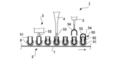
以下、本発明の実施の形態について、添付図面を参照して説明する。図1は、 本発明の一実施形態に係る電子タグ付きカプセル製造装置の概略構成図である。図1に示すように、電子タグ付きカプセル製造装置1は、カプセルボディ51を搬送する搬送装置2と、カプセルボディ51に電子タグ52を装着する電子タグ装着装置3と、カプセルボディ51に粉末、顆粒、液体、錠剤等の充填物53を供給する充填物供給装置4と、カプセルボディ51にキャップ54を結合するキャップ結合装置5とを備えている。電子タグ装着装置3、充填物供給装置4およびキャップ結合装置5は、搬送装置2の搬送方向に沿って上流側からこの順で配置されている。
Hereinafter, embodiments of the present invention will be described with reference to the accompanying drawings. FIG. 1 is a schematic configuration diagram of an electronic tag-equipped capsule manufacturing apparatus according to an embodiment of the present invention. As shown in FIG. 1, the capsule manufacturing
搬送装置2は、コンベア7上に椀状の支持部材8を多数備えており、カプセルボディ51の下部が支持部材8に収容されることにより、カプセルボディ51が起立状態で支持される。搬送装置2は、電子タグ装着装置3、充填物供給装置4およびキャップ結合装置5のそれぞれに対応する位置でカプセルボディ51を停止させるように間欠駆動され、これによって、カプセルボディ51とキャップ54との結合により電子タグ52および充填物53が封入されたカプセル50が製造される。
The
本実施形態の搬送装置2は、カプセルボディ51を一方向に搬送する構成としているが、ターンテーブルを使用することも可能であり、テーブルの割出位置に対応して、電子タグ装着装置3、充填物供給装置4およびキャップ結合装置5を配置してもよい。また、電子タグ付きカプセル製造装置1は、充填物供給装置4を備えない構成であってもよく、カプセルボディ51に電子タグ52のみを装着してキャップ54を仮結合した電子タグ付きカプセルを製造し、充填物53の供給は、後工程で別の装置により行うことも可能である。
Although the
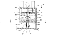
図2は、図1に示す電子タグ付きカプセル製造装置1の要部である電子タグ装着装置3の断面図である。図2に示すように、電子タグ装着装置3は、搬送装置2の近傍から起立するベース10の天板に取り付けられたエアシリンダ11を備えている。エアシリンダ11は、先端(下端)に取り付けられた支持プレート12を上下動可能に支持する。支持プレート12の中央には貫通孔が形成されており、この貫通孔にベアリング13を介して保持体14が挿通されている。
FIG. 2 is a cross-sectional view of the electronic tag mounting apparatus 3 which is a main part of the
保持体14は、基部側が拡径された筒状の部材であり、先端部外周面に吸着部15が設けられている。吸着部15は、外周面の軸方向に2つ形成された主吸着孔15aと、主吸着孔15aから外周面に沿って90度離間した位置に1つ形成された副吸着孔15bとを備えている。
The
保持体14の基端部は、支持プレート12に取り付けられたロータリージョイント16を介して、吸引管17に接続されている。吸引管17は、真空ポンプ(図示せず)に接続され、保持体14の内部に形成された吸引路14aを介して、吸着部15からエアを吸引することができる。吸引路14aの内圧は、圧力センサ18により検出される。
A base end portion of the
支持プレート12には、駆動モータ19が取り付けられている。駆動モータ19は、出力軸が鉛直下方を向くように支持されており、出力軸19には駆動ギヤ20が設けられている。駆動ギヤ20は、保持体14に外嵌された従動ギヤ21に噛合しており、駆動モータ19の作動により、保持体14が矢示のように軸線回りの両方向に回転する。
A
支持プレート12の下方には、ベース10に支持されたガイド部材22が設けられている。ガイド部材22には、吸着部15が挿入される貫通孔23が形成されており、吸着部15の外周面と貫通孔23の内周面との間には若干の隙間が形成される。貫通孔23の下方には、搬送装置2の作動により、支持部材8に支持されたカプセルボディ51が搬送される。支持部材8は、停止位置において、カプセルボディ51を内部が貫通孔23と対向するように支持する。 吸着部15は、図2に示すように、貫通孔23に挿入された位置から、エアシリンダ11の作動により下方に進出すると、図3に示すように、カプセルボディ51内に挿入される。
A
図4は、図2のA−A断面の一部を拡大して示す図である。ガイド部材22の貫通孔23には、内周面の接線方向に延びて外部と連通する切欠状の導入部24が形成されており、可撓性薄板状の電子タグ52を、導入部24から吸着部15と貫通孔23との隙間に供給することができる。本実施形態の電子タグ装着装置3は、多軸ロボットからなる供給装置26を備えており、パレット(図示せず)に複数搭載された電子タグ52を、供給装置26のアーム先端に設けられた吸引部26aに吸引してガイド部材22に矢示B方向に押し付けた後、矢示C方向にスライドさせることにより、電子タグ52の端部を貫通孔23内に供給することができる。導入部24の外方端には、電子タグ52の挿入を促すようにガイド面25が連続している。ガイド面25を形成する代わりに、ガイドローラ等により電子タグ52を貫通孔23に案内することも可能である。
4 is an enlarged view of a part of the AA cross section of FIG. A
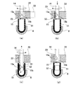
次に、図5および図6を参照して、上記の構成を備える電子タグ付きカプセル製造装置1の作動を説明する。図5および図6は、それぞれ電子タグ付きカプセル製造装置1の要部断面図および要部平面図である。本実施形態の電子タグ付きカプセル製造装置1は、上記のように保持体14が回転および進退可能とされており、制御装置(図示せず)により下記の駆動制御が行われる。
Next, the operation of the electronic tag-equipped
まず、図5(a)に示すように、保持体14の吸着部15をガイド部材22の貫通孔23内に挿入する(挿入ステップ)。ついで、図5(a)および図6(a)に示すように、導入部24を介して電子タグ52を貫通孔23内に供給する(供給ステップ)。吸着部15の主吸着孔15aは、導入部24から電子タグ52の挿入方向に約90度離隔した位置で停止しており、挿入された電子タグ52の端部と対向する。
First, as shown in FIG. 5A, the
図5(a)および図6(a)に示す状態から、真空ポンプ(図示せず)を作動させて電子タグ52の端部を吸着部15の主吸着孔15aおよび副吸着孔15bに吸着した後、保持体14を矢示方向に回転させると、図5(b)に示すように、電子タグ52が貫通孔23の内周面によりガイドされながら、保持体14の外周面に巻き付けられる。電子タグ52は、図6(b)に示すように、吸着部15の周方向全体を覆うように巻き付けられることが好ましく、電子タグ52の一部が重なり合うように巻き付けられてもよい。
From the state shown in FIG. 5A and FIG. 6A, a vacuum pump (not shown) is operated to adsorb the end of the
保持体14に電子タグ52が巻き付けられると、主吸着孔15aおよび副吸着孔15bが電子タグ52により密閉されるため、保持体14内部の吸引路の圧力は低下する。吸引路内の圧力は、圧力センサ18により常時検出され、圧力センサ18の検出値が所定値以下の場合に、制御装置は、保持体14を下方に進出させて、図5(c)に示すように電子タグ52をカプセルボディ51内に配置する(収容ステップ)。保持体14の進出は、保持体14の回転を維持したまま行うことが好ましく、これによって、電子タグ52の巻き付け状態を確実にして保持体14を進出させることができる。
When the
一方、圧力センサ18の検出値が所定値より大きい場合には、主吸着孔15a,15aおよび副吸着孔15bの少なくとも一部に電子タグ52が密着していないおそれがあるため、制御装置は、保持体14の進出を行わずに警報音等を発して作動を中断する。こうして、保持体14に正しく巻き付けられた電子タグ52のみをカプセルボディ51内に配置することができる。
On the other hand, when the detected value of the
図5(c)に示すように、電子タグ52をカプセルボディ51内に配置した後、吸着部15における吸着を解除すると、保持体14に巻き付けられていた電子タグ52は撓みの力で外方に拡がり、カプセルボディ51の内周面に密着する。カプセルボディ51に電子タグ52が確実に密着するように、電子タグ52は、少なくともカプセルボディ51の周方向全体を覆う長さを有することが好ましく、電子タグ52の一部が重なり合ってもよい。
As shown in FIG. 5C, after the
ついで、吸着部15を上方に退避させると、図5(d)に示すように、吸着部15は、電子タグ52をカプセルボディ51に残して貫通孔23内に再び配置される(退避ステップ)。吸着部15を退避させる際には、図5(c)に矢示するように、電子タグ52を巻き解く方向に保持体14を回転させながら行うことが好ましく、電子タグ52がカプセルボディ51の内周面に密着するのを促して、保持体14と共に電子タグ52が引き上げられるのを確実に防止することができる。この後は、貫通孔23の下方に新たなカプセルボディ51を搬送し、図5(a)に示すように、貫通孔23に新たな電子タグ52を供給することで、電子タグ付きカプセルを順次製造することができる。
Next, when the
本実施形態の電子タグ付きカプセル製造装置1は、カプセルボディ51の内周面に沿って電子タグ52を確実に密着させることができるので、充填物の充填が容易な電子タグ付きカプセルを効率良く製造することができる。
Since the electronic tag-equipped
1 電子タグ付きカプセル製造装置
3 電子タグ装着装置
8 支持部材
11 エアシリンダ
14 保持体
15 吸着部
22 ガイド部材
23 貫通孔
24 導入部
26 供給装置
51 カプセルボディ
52 電子タグ
DESCRIPTION OF
Claims (5)
筒状の保持体の先端部外周面に設けられた吸着部を、ガイド部材に形成された貫通孔内に挿入する挿入ステップと、
前記貫通孔に案内する切欠状の導入部を介して、電子タグの端部を前記貫通孔内に供給する供給ステップと、
前記貫通孔内に供給された前記電子タグの端部を前記貫通孔内に挿入された前記吸着部に吸着して、前記保持体の回転により前記電子タグを前記保持体の外周面に巻き付け、前記保持体の進出により前記電子タグをカプセルボディ内に配置する収容ステップと、
前記吸着部による前記電子タグの吸着を解除して、前記吸着部を前記カプセルボディから退避させる退避ステップとを備える電子タグ付きカプセルの製造方法。 A method of manufacturing a capsule with an electronic tag by attaching an electronic tag including a flexible substrate to a capsule body,
An insertion step of inserting the suction portion provided on the outer peripheral surface of the distal end portion of the cylindrical holder into a through hole formed in the guide member;
A supply step of supplying an end portion of the electronic tag into the through-hole through a notch-shaped introduction portion guided to the through-hole;
The end of the electronic tag supplied into the through hole is adsorbed to the adsorption part inserted into the through hole, and the electronic tag is wound around the outer peripheral surface of the holding body by rotation of the holding body, An accommodating step of arranging the electronic tag in the capsule body by advancement of the holding body,
A method of manufacturing a capsule with an electronic tag, comprising: a retraction step of releasing the adsorption of the electronic tag by the adsorption unit and retracting the adsorption unit from the capsule body.
先端部外周面に吸着部を有する筒状の保持体と、
前記吸着部が挿入される貫通孔を有し、前記貫通孔に案内する切欠状の導入部を介して前記貫通孔に電子タグを供給可能なガイド部材と、
前記導入部を介して前記貫通孔に電子タグを供給する供給手段と、
カプセルボディを内部が前記貫通孔と対向するように支持する支持部材とを備え、
前記保持体は回転および進退可能とされており、前記貫通孔内に供給された前記電子タグの端部を前記貫通孔内に挿入された前記吸着部に吸着して前記吸着部を前記貫通孔内で回転させることにより前記保持体の外周面に巻き付けた前記電子タグを、前記保持体の進出によりカプセルボディ内に配置する電子タグ付きカプセルの製造装置。 An apparatus for manufacturing a capsule with an electronic tag by attaching an electronic tag including a flexible substrate to a capsule body,
A cylindrical holder having a suction portion on the outer peripheral surface of the tip,
A guide member having a through-hole into which the suction part is inserted, and capable of supplying an electronic tag to the through-hole through a notch-shaped introduction part guided to the through-hole;
Supply means for supplying an electronic tag to the through-hole through the introduction part;
A support member for supporting the capsule body so that the inside faces the through hole,
The holding body is capable of rotating and advancing and retreating, and adsorbs an end portion of the electronic tag supplied into the through hole to the adsorbing portion inserted into the through hole so that the adsorbing portion is moved to the through hole. the electronic tag wound around the outer peripheral surface of the holding member by rotating the inner, electronic tagged capsule manufacturing apparatus for placement within the capsule body by advancement of the retaining member.
Priority Applications (1)
| Application Number | Priority Date | Filing Date | Title |
|---|---|---|---|
| JP2015137645A JP6567346B2 (en) | 2015-07-09 | 2015-07-09 | Method and apparatus for manufacturing capsule with electronic tag |
Applications Claiming Priority (1)
| Application Number | Priority Date | Filing Date | Title |
|---|---|---|---|
| JP2015137645A JP6567346B2 (en) | 2015-07-09 | 2015-07-09 | Method and apparatus for manufacturing capsule with electronic tag |
Publications (2)
| Publication Number | Publication Date |
|---|---|
| JP2017018239A JP2017018239A (en) | 2017-01-26 |
| JP6567346B2 true JP6567346B2 (en) | 2019-08-28 |
Family
ID=57886965
Family Applications (1)
| Application Number | Title | Priority Date | Filing Date |
|---|---|---|---|
| JP2015137645A Expired - Fee Related JP6567346B2 (en) | 2015-07-09 | 2015-07-09 | Method and apparatus for manufacturing capsule with electronic tag |
Country Status (1)
| Country | Link |
|---|---|
| JP (1) | JP6567346B2 (en) |
Families Citing this family (3)
| Publication number | Priority date | Publication date | Assignee | Title |
|---|---|---|---|---|
| CN108272638A (en) * | 2017-12-20 | 2018-07-13 | 佛山杰致信息科技有限公司 | A kind of biological medicine of optimization pellet processing machine device |
| US20220273520A1 (en) * | 2019-08-02 | 2022-09-01 | Qualicaps Co., Ltd. | Hard capsule formulation sealed with band seal containing tags |
| CN119345038B (en) * | 2024-11-11 | 2025-09-30 | 江西德瑞制药有限公司 | A Chinese medicine filling device and filling method for hard capsule production |
Family Cites Families (3)
| Publication number | Priority date | Publication date | Assignee | Title |
|---|---|---|---|---|
| JP2003017514A (en) * | 2001-03-20 | 2003-01-17 | Schlumberger Holding Ltd | Electronic tag device and method of packaging electronic tag |
| US20140309505A1 (en) * | 2005-07-20 | 2014-10-16 | Etect, Inc | Electronic medication compliance monitoring system and associated methods |
| EP2763645B8 (en) * | 2011-10-06 | 2016-09-14 | Binutra Incorporated | A method and apparatus for manufacturing a capsule |
-
2015
- 2015-07-09 JP JP2015137645A patent/JP6567346B2/en not_active Expired - Fee Related
Also Published As
| Publication number | Publication date |
|---|---|
| JP2017018239A (en) | 2017-01-26 |
Similar Documents
| Publication | Publication Date | Title |
|---|---|---|
| TWI507189B (en) | The combination of container cover | |
| JP6567346B2 (en) | Method and apparatus for manufacturing capsule with electronic tag | |
| TWI419787B (en) | Apparatus for punching stiffener and stiffener-attaching system using the same | |
| TWI483338B (en) | A posture correction device, an electronic component handling device, and an electronic component transfer device | |
| JP4652487B2 (en) | Component mounting apparatus and method | |
| KR20110050647A (en) | Mounting apparatus and mounting method | |
| TWI591738B (en) | Bonding machine | |
| KR20140031009A (en) | Electric chip carrier tape feeding deive and electric chip carrier tape feeding method | |
| US20130074447A1 (en) | Carrier tape winding unit and apparatus of packing semiconductor package | |
| CN104994827B (en) | Pharmaceutical tablet and its manufacturing method and manufacturing device | |
| JP2011121619A (en) | Labeling machine | |
| JP5051783B2 (en) | Container lid joining method | |
| CN117790392A (en) | Automatic integrated circuit wafer aligning feeding and discharging device | |
| JP5185422B2 (en) | Labeling device | |
| JP2006008153A (en) | Apparatus for sticking label wound on body | |
| JP2006069567A (en) | Label affixing method and affixing apparatus | |
| JP2014088202A (en) | Sheet fitting device and sheet fitting method | |
| JP4758321B2 (en) | Packaging apparatus and packaging method | |
| KR101826270B1 (en) | An automatic writing apparatus of a semiconductor device | |
| JP7133297B2 (en) | Elongated object conveying device and elongated object conveying method | |
| KR101669150B1 (en) | A printing device of automatic medicine packing machine | |
| JPH07187162A (en) | Labeling machine | |
| JP2013098323A (en) | Support device and support method, sheet peeling device and peeling method, and sheet sticking device and sticking method | |
| CN101740443A (en) | Roller for guiding of flexible printed circut film and apparatus for packaging semiconductor with the same | |
| JPH08236988A (en) | Polarity alignment device for electronic parts |
Legal Events
| Date | Code | Title | Description |
|---|---|---|---|
| A621 | Written request for application examination |
Free format text: JAPANESE INTERMEDIATE CODE: A621 Effective date: 20180530 |
|
| A131 | Notification of reasons for refusal |
Free format text: JAPANESE INTERMEDIATE CODE: A131 Effective date: 20190329 |
|
| A977 | Report on retrieval |
Free format text: JAPANESE INTERMEDIATE CODE: A971007 Effective date: 20190327 |
|
| A521 | Request for written amendment filed |
Free format text: JAPANESE INTERMEDIATE CODE: A523 Effective date: 20190417 |
|
| TRDD | Decision of grant or rejection written | ||
| A01 | Written decision to grant a patent or to grant a registration (utility model) |
Free format text: JAPANESE INTERMEDIATE CODE: A01 Effective date: 20190705 |
|
| A61 | First payment of annual fees (during grant procedure) |
Free format text: JAPANESE INTERMEDIATE CODE: A61 Effective date: 20190731 |
|
| R150 | Certificate of patent or registration of utility model |
Ref document number: 6567346 Country of ref document: JP Free format text: JAPANESE INTERMEDIATE CODE: R150 |
|
| R250 | Receipt of annual fees |
Free format text: JAPANESE INTERMEDIATE CODE: R250 |
|
| R250 | Receipt of annual fees |
Free format text: JAPANESE INTERMEDIATE CODE: R250 |
|
| LAPS | Cancellation because of no payment of annual fees |