JP6542693B2 - Solvent separation method, solvent separation device and solvent separation system - Google Patents
Solvent separation method, solvent separation device and solvent separation system Download PDFInfo
- Publication number
- JP6542693B2 JP6542693B2 JP2016033508A JP2016033508A JP6542693B2 JP 6542693 B2 JP6542693 B2 JP 6542693B2 JP 2016033508 A JP2016033508 A JP 2016033508A JP 2016033508 A JP2016033508 A JP 2016033508A JP 6542693 B2 JP6542693 B2 JP 6542693B2
- Authority
- JP
- Japan
- Prior art keywords
- solvent
- solvent separation
- recovery
- gas
- casing
- Prior art date
- Legal status (The legal status is an assumption and is not a legal conclusion. Google has not performed a legal analysis and makes no representation as to the accuracy of the status listed.)
- Active
Links
Images




Classifications
-
- B—PERFORMING OPERATIONS; TRANSPORTING
- B01—PHYSICAL OR CHEMICAL PROCESSES OR APPARATUS IN GENERAL
- B01D—SEPARATION
- B01D5/00—Condensation of vapours; Recovering volatile solvents by condensation
- B01D5/0057—Condensation of vapours; Recovering volatile solvents by condensation in combination with other processes
-
- B—PERFORMING OPERATIONS; TRANSPORTING
- B03—SEPARATION OF SOLID MATERIALS USING LIQUIDS OR USING PNEUMATIC TABLES OR JIGS; MAGNETIC OR ELECTROSTATIC SEPARATION OF SOLID MATERIALS FROM SOLID MATERIALS OR FLUIDS; SEPARATION BY HIGH-VOLTAGE ELECTRIC FIELDS
- B03C—MAGNETIC OR ELECTROSTATIC SEPARATION OF SOLID MATERIALS FROM SOLID MATERIALS OR FLUIDS; SEPARATION BY HIGH-VOLTAGE ELECTRIC FIELDS
- B03C3/00—Separating dispersed particles from gases or vapour, e.g. air, by electrostatic effect
- B03C3/01—Pretreatment of the gases prior to electrostatic precipitation
-
- B—PERFORMING OPERATIONS; TRANSPORTING
- B01—PHYSICAL OR CHEMICAL PROCESSES OR APPARATUS IN GENERAL
- B01D—SEPARATION
- B01D5/00—Condensation of vapours; Recovering volatile solvents by condensation
- B01D5/0057—Condensation of vapours; Recovering volatile solvents by condensation in combination with other processes
- B01D5/006—Condensation of vapours; Recovering volatile solvents by condensation in combination with other processes with evaporation or distillation
-
- B—PERFORMING OPERATIONS; TRANSPORTING
- B01—PHYSICAL OR CHEMICAL PROCESSES OR APPARATUS IN GENERAL
- B01D—SEPARATION
- B01D5/00—Condensation of vapours; Recovering volatile solvents by condensation
- B01D5/0027—Condensation of vapours; Recovering volatile solvents by condensation by direct contact between vapours or gases and the cooling medium
-
- B—PERFORMING OPERATIONS; TRANSPORTING
- B01—PHYSICAL OR CHEMICAL PROCESSES OR APPARATUS IN GENERAL
- B01D—SEPARATION
- B01D5/00—Condensation of vapours; Recovering volatile solvents by condensation
- B01D5/0033—Other features
- B01D5/0051—Regulation processes; Control systems, e.g. valves
-
- B—PERFORMING OPERATIONS; TRANSPORTING
- B01—PHYSICAL OR CHEMICAL PROCESSES OR APPARATUS IN GENERAL
- B01D—SEPARATION
- B01D5/00—Condensation of vapours; Recovering volatile solvents by condensation
- B01D5/0033—Other features
- B01D5/0054—General arrangements, e.g. flow sheets
-
- B—PERFORMING OPERATIONS; TRANSPORTING
- B01—PHYSICAL OR CHEMICAL PROCESSES OR APPARATUS IN GENERAL
- B01D—SEPARATION
- B01D5/00—Condensation of vapours; Recovering volatile solvents by condensation
- B01D5/0078—Condensation of vapours; Recovering volatile solvents by condensation characterised by auxiliary systems or arrangements
- B01D5/009—Collecting, removing and/or treatment of the condensate
-
- B—PERFORMING OPERATIONS; TRANSPORTING
- B01—PHYSICAL OR CHEMICAL PROCESSES OR APPARATUS IN GENERAL
- B01D—SEPARATION
- B01D53/00—Separation of gases or vapours; Recovering vapours of volatile solvents from gases; Chemical or biological purification of waste gases, e.g. engine exhaust gases, smoke, fumes, flue gases, aerosols
- B01D53/002—Separation of gases or vapours; Recovering vapours of volatile solvents from gases; Chemical or biological purification of waste gases, e.g. engine exhaust gases, smoke, fumes, flue gases, aerosols by condensation
-
- B—PERFORMING OPERATIONS; TRANSPORTING
- B01—PHYSICAL OR CHEMICAL PROCESSES OR APPARATUS IN GENERAL
- B01D—SEPARATION
- B01D53/00—Separation of gases or vapours; Recovering vapours of volatile solvents from gases; Chemical or biological purification of waste gases, e.g. engine exhaust gases, smoke, fumes, flue gases, aerosols
- B01D53/32—Separation of gases or vapours; Recovering vapours of volatile solvents from gases; Chemical or biological purification of waste gases, e.g. engine exhaust gases, smoke, fumes, flue gases, aerosols by electrical effects other than those provided for in group B01D61/00
- B01D53/323—Separation of gases or vapours; Recovering vapours of volatile solvents from gases; Chemical or biological purification of waste gases, e.g. engine exhaust gases, smoke, fumes, flue gases, aerosols by electrical effects other than those provided for in group B01D61/00 by electrostatic effects or by high-voltage electric fields
-
- B—PERFORMING OPERATIONS; TRANSPORTING
- B03—SEPARATION OF SOLID MATERIALS USING LIQUIDS OR USING PNEUMATIC TABLES OR JIGS; MAGNETIC OR ELECTROSTATIC SEPARATION OF SOLID MATERIALS FROM SOLID MATERIALS OR FLUIDS; SEPARATION BY HIGH-VOLTAGE ELECTRIC FIELDS
- B03C—MAGNETIC OR ELECTROSTATIC SEPARATION OF SOLID MATERIALS FROM SOLID MATERIALS OR FLUIDS; SEPARATION BY HIGH-VOLTAGE ELECTRIC FIELDS
- B03C3/00—Separating dispersed particles from gases or vapour, e.g. air, by electrostatic effect
- B03C3/01—Pretreatment of the gases prior to electrostatic precipitation
- B03C3/014—Addition of water; Heat exchange, e.g. by condensation
-
- B—PERFORMING OPERATIONS; TRANSPORTING
- B03—SEPARATION OF SOLID MATERIALS USING LIQUIDS OR USING PNEUMATIC TABLES OR JIGS; MAGNETIC OR ELECTROSTATIC SEPARATION OF SOLID MATERIALS FROM SOLID MATERIALS OR FLUIDS; SEPARATION BY HIGH-VOLTAGE ELECTRIC FIELDS
- B03C—MAGNETIC OR ELECTROSTATIC SEPARATION OF SOLID MATERIALS FROM SOLID MATERIALS OR FLUIDS; SEPARATION BY HIGH-VOLTAGE ELECTRIC FIELDS
- B03C3/00—Separating dispersed particles from gases or vapour, e.g. air, by electrostatic effect
- B03C3/34—Constructional details or accessories or operation thereof
- B03C3/40—Electrode constructions
- B03C3/45—Collecting-electrodes
- B03C3/47—Collecting-electrodes flat, e.g. plates, discs, gratings
-
- B—PERFORMING OPERATIONS; TRANSPORTING
- B01—PHYSICAL OR CHEMICAL PROCESSES OR APPARATUS IN GENERAL
- B01D—SEPARATION
- B01D2257/00—Components to be removed
- B01D2257/70—Organic compounds not provided for in groups B01D2257/00 - B01D2257/602
- B01D2257/704—Solvents not covered by groups B01D2257/702 - B01D2257/7027
-
- B—PERFORMING OPERATIONS; TRANSPORTING
- B01—PHYSICAL OR CHEMICAL PROCESSES OR APPARATUS IN GENERAL
- B01D—SEPARATION
- B01D2257/00—Components to be removed
- B01D2257/70—Organic compounds not provided for in groups B01D2257/00 - B01D2257/602
- B01D2257/708—Volatile organic compounds V.O.C.'s
Landscapes
- Chemical & Material Sciences (AREA)
- Chemical Kinetics & Catalysis (AREA)
- Engineering & Computer Science (AREA)
- Analytical Chemistry (AREA)
- General Chemical & Material Sciences (AREA)
- Oil, Petroleum & Natural Gas (AREA)
- Automation & Control Theory (AREA)
- Treating Waste Gases (AREA)
- Vaporization, Distillation, Condensation, Sublimation, And Cold Traps (AREA)
- Drying Of Gases (AREA)
- Electrostatic Separation (AREA)
Description
本発明は、気化した溶媒を含む気体から、溶媒を除去する溶媒分離方法、溶媒分離装置及び溶媒分離システムに関するものである。 The present invention relates to a solvent separation method, a solvent separation apparatus, and a solvent separation system for removing a solvent from a gas containing a vaporized solvent.
近年、家電等の様々な工業製品の組み立て製造工程、又は、これらの製品の構成部品となる電子部品、電池、若しくは、基板などのデバイス製造工程において、各種の機能を持ったペースト状の材料を塗布したのち、熱処理装置によって加熱処理が行われている。熱処理装置は、例えば、乾燥炉、焼成炉、キュア炉、もしくはリフロー炉などである。リフロー炉は、電子部品の実装工程などではんだ付けに使用される。ペースト状の材料には、最終的に製品に必要とされる固形分などに加え、水又は有機溶剤などの各種の溶媒が混入されて粘度調整又は性能調整が施されている。 In recent years, paste-like materials with various functions have been used in the assembly and manufacturing processes of various industrial products such as home appliances, or in the device manufacturing processes such as electronic components, batteries, and substrates to be components of these products. After application, heat treatment is performed by a heat treatment apparatus. The heat treatment apparatus is, for example, a drying furnace, a baking furnace, a curing furnace, or a reflow furnace. A reflow furnace is used for soldering in an electronic component mounting process or the like. The paste-like material is mixed with various solvents such as water or an organic solvent in addition to the solid content and the like finally required for the product, and viscosity adjustment or performance adjustment is performed.
ペースト状の材料に含まれている溶媒は、熱処理装置における加熱工程で、気化及び脱媒の工程を経て、ペースト状の材料から熱処理装置内に放出される。熱処理装置内において気化した溶媒の濃度が上がると、様々な不具合につながる可能性がある。例えば、熱処理装置内の雰囲気の溶媒濃度が飽和状態に近づくと、熱処理対象物の乾燥が困難となる可能性がある。そのため、熱処理装置内に外気や窒素ガス又はその他の雰囲気ガスを定期的又は連続的に供給するとともに、溶媒濃度が上昇した熱処理装置内の雰囲気を外部に放出する。 The solvent contained in the paste-like material is released from the paste-like material into the heat treatment apparatus through the steps of evaporation and demixing in the heating step of the heat treatment apparatus. An increase in the concentration of the vaporized solvent in the heat treatment apparatus can lead to various problems. For example, when the solvent concentration of the atmosphere in the heat treatment apparatus approaches saturation, drying of the heat treatment target may be difficult. Therefore, outside air, nitrogen gas, or other atmosphere gas is periodically or continuously supplied into the heat treatment apparatus, and the atmosphere in the heat treatment apparatus in which the solvent concentration is increased is released to the outside.
図10は、熱処理装置1に対する外気の供給及び雰囲気の排気を説明する図である。送風ブロア2は、熱処理装置1の内部に外気を供給する。排気ブロア3は、気化した溶媒を含んだ雰囲気の一部を熱処理装置外に排出する。ただし、溶媒が熱処理装置外に排出されると、環境への影響が懸念される場合がある。そこで、熱処理装置外に排出する排気雰囲気から溶媒を除去する方法として、例えば特許文献1の方式が知られている。
FIG. 10 is a view for explaining the supply of the outside air to the heat treatment apparatus 1 and the exhaust of the atmosphere. The
図11は特許文献1の説明図である。特許文献1では、熱処理装置1の熱処理装置内排気ダクト4に対して、冷却器5、熱処理装置外排気ダクト6、及びミストコレクタ7が順に接続されている。冷却器5は、熱処理装置1から排出される排気雰囲気を冷却することで、排気雰囲気に含まれる気化した溶媒を液化させる。液化した溶媒を含む排気雰囲気は、熱処理装置外排気ダクト6を介してミストコレクタ7に送られ、ミストコレクタ7で、液化した溶媒を捕捉して除去する。これにより、熱処理装置1から排出する排気雰囲気から溶媒を除去することができる。
FIG. 11 is an explanatory view of Patent Document 1. In FIG. In Patent Document 1, the
しかしながら、冷却器5で液化した溶媒は、排気経路に付着しやすくなる。特許文献1の構成では、液化した溶媒の一部は、ミストコレクタ7で捕捉されるだけでなく、冷却器5及び熱処理装置外排気ダクト6などの排気経路にも付着する。排気経路に溶媒が付着して蓄積していくと、排気雰囲気を浄化処理する能力が低下する。このため定期的に排気経路を分解して、排気経路に蓄積した溶媒を除去するメンテナンスを行う必要がある。
However, the solvent liquefied by the
特許文献1の構成では、液化した溶媒がミストコレクタ7だけでなく、冷却器5及び熱処理装置外排気ダクト6にも付着して残留するため、排気経路を分解して溶媒を除去するメンテナンスが必要で手数が掛かる。また、メンテナンスに手数が掛かることにより、熱処理装置1を長期間停止させる必要があるため、熱処理装置1の稼働率を低下させることとなる。
In the configuration of Patent Document 1, the liquefied solvent adheres and remains not only to the
本発明は、このような点に鑑み、排気雰囲気から除去した溶媒を容易に回収可能とし、排気経路のメンテナンスを容易に行うことができる、溶媒分離方法、溶媒分離装置及び溶媒分離システムを提供することを目的とする。 In view of such a point, the present invention provides a solvent separation method, a solvent separation apparatus, and a solvent separation system, which can easily recover the solvent removed from the exhaust atmosphere and easily perform maintenance of the exhaust path. The purpose is
本発明の第1の態様にかかる溶媒分離方法は、気化した溶媒を含む気体から、前記溶媒を除去する溶媒分離方法であって、
ケーシングの収容空間に収容された羽根車を回転させることにより、前記気化した溶媒を含んだ気体を前記ケーシングの取り入れ口から前記収容空間に取り入れる工程と、
前記収容空間に取り入れた前記気化した溶媒を、表面温度が前記気体の温度よりも低温となるように冷却された回収面で冷却して液化させることで、前記気体から前記溶媒を分離する工程とを含む、溶媒分離方法である。
The solvent separation method according to the first aspect of the present invention is a solvent separation method for removing the solvent from a gas containing a vaporized solvent,
Introducing the gas containing the vaporized solvent from the intake of the casing into the accommodation space by rotating an impeller accommodated in the accommodation space of the casing;
Separating the solvent from the gas by cooling and liquefying the vaporized solvent taken into the storage space on a recovery surface cooled so that the surface temperature is lower than the temperature of the gas; And a solvent separation method.
本発明の第2の態様にかかる溶媒分離方法は、前記第1の態様において、前記気化した溶媒を含んだ気体を前記収容空間に取り入れる工程の前に、前記気化した溶媒を含んだ気体に対し、前記気化した溶媒を凝集させる工程を含む、溶媒分離方法である。 In the solvent separation method according to the second aspect of the present invention, in the first aspect, the gas containing the vaporized solvent is introduced into the containing space before the step of introducing the gas containing the vaporized solvent to the gas containing the vaporized solvent. A solvent separation method comprising the step of aggregating the vaporized solvent.
本発明の第3の態様にかかる溶媒分離方法は、前記第1または第2の態様において、前記気体から前記溶媒を分離する工程に続いて、前記溶媒を分離した気体に電界をかけて、前記気体に残存する気化した溶媒を分離する工程を含む、溶媒分離方法である。 In the solvent separation method according to the third aspect of the present invention, in the first or second aspect, following the step of separating the solvent from the gas, an electric field is applied to the gas from which the solvent has been separated, A solvent separation method comprising the step of separating a vaporized solvent remaining in a gas.
また、本発明の第4の態様にかかる溶媒分離装置は、回転軸回りに複数の羽根が配列され、前記回転軸を中心として回転可能な羽根車を有するとともに、前記羽根車を収容する収容空間と、前記気体を前記収容空間に取り入れる取り入れ口と、前記気体を前記収容空間から排出する排出口と、を有するケーシングと、
前記収容空間に面した回収面を有し、前記回収面の表面温度が、前記取り入れ口から取り入れられる気体の温度よりも低温となるように冷却される回収部と、を備え、
前記羽根車が回転することにより、気化した溶媒を含んだ気体を前記取り入れ口から前記収容空間に取り入れ、前記回収面で前記気化した溶媒を冷却し液化させることで、前記気体から前記溶媒を分離する溶媒分離装置である。
The solvent separation device according to the fourth aspect of the present invention has a plurality of blades arranged around the rotation axis, and has an impeller rotatable around the rotation axis, and a storage space for housing the impeller. A casing having an inlet for introducing the gas into the storage space, and an outlet for discharging the gas from the storage space;
And a recovery unit having a recovery surface facing the housing space, wherein a surface temperature of the recovery surface is cooled to a temperature lower than a temperature of a gas introduced from the inlet.
When the impeller rotates, a gas containing a vaporized solvent is taken into the storage space from the intake, and the vaporized solvent is cooled and liquefied on the recovery surface to separate the solvent from the gas Solvent separation device.
本発明の第5の態様にかかる溶媒分離装置は、前記第4の態様において、前記回収面は、前記ケーシングの内面で構成される溶媒分離装置である。 The solvent separation apparatus according to a fifth aspect of the present invention is the solvent separation apparatus according to the fourth aspect, wherein the recovery surface is an inner surface of the casing.
本発明の第6の態様にかかる溶媒分離装置は、前記第4または第5の態様において、前記ケーシングは、前記回収面を含む第1部分と、前記第1部分以外の第2部分とに分解可能に構成され、前記ケーシングを分解して前記回収面のメンテナンスが可能な、溶媒分離装置である。 In the solvent separation device according to a sixth aspect of the present invention, in the fourth or fifth aspect, the casing is decomposed into a first portion including the recovery surface and a second portion other than the first portion. It is a solvent separation device that is configured and capable of disassembling the casing and maintaining the recovery surface.
本発明の第7の態様にかかる溶媒分離装置は、前記第4から第6のいずれか1つの態様において、前記回収部は、前記ケーシングから分離可能とした、溶媒分離装置である。 The solvent separation apparatus according to a seventh aspect of the present invention is the solvent separation apparatus according to any one of the fourth to sixth aspects, wherein the recovery unit is separable from the casing.
本発明の第8の態様にかかる溶媒分離装置は、前記第4から第7のいずれか1つの態様において、前記取り入れ口は、前記ケーシングの前記回転軸に交差する面に配置され、前記排出口は、前記回転軸に交差する方向に向けて配置されており、前記回収面は、前記ケーシングの内面のうち、前記取り入れ口が配置される面に対向した面に配置される、溶媒分離装置である。 In the solvent separation device according to the eighth aspect of the present invention, in any one of the fourth to seventh aspects, the inlet is disposed on a surface intersecting the rotation axis of the casing, and the outlet Is disposed in a direction intersecting with the rotation axis, and the recovery surface is disposed on a surface of the inner surface of the casing opposite to the surface on which the inlet is disposed. is there.
本発明の第9の態様にかかる溶媒分離装置は、前記第8の態様において、前記回転軸に沿う方向を第1方向とし、前記第1方向から見て、前記回収面は、前記羽根車に対して半径方向外側に配置されている、溶媒分離装置である。 In the solvent separation device according to a ninth aspect of the present invention, in the eighth aspect, a direction along the rotation axis is a first direction, and the recovery surface is a portion of the impeller as viewed from the first direction. It is a solvent separation device, which is arranged radially outward with respect to it.
本発明の第10の態様にかかる溶媒分離装置は、前記第4から第9のいずれか1つの態様において、前記ケーシングに断熱材が配置されている領域を断熱領域とし、断熱材が配置されていない領域を放熱領域として、前記回収面は、前記放熱領域に配置されている、溶媒分離装置である。 In the solvent separation device according to the tenth aspect of the present invention, in any one of the fourth to ninth aspects, the region where the heat insulating material is disposed in the casing is a heat insulating region, and the heat insulating material is disposed. It is a solvent separation device in which the recovery surface is disposed in the heat radiation area, where the non-area is a heat radiation area.
本発明の第11の態様にかかる溶媒分離装置は、前記第4から第10のいずれか1つの態様において、前記回収部は、前記回収面の表面積を拡大するための表面積拡大部を有する、溶媒分離装置である。 The solvent separation device according to an eleventh aspect of the present invention is the solvent separation device according to any one of the fourth to tenth aspects, wherein the recovery unit has a surface area expansion portion for expanding the surface area of the recovery surface. It is a separation device.
本発明の第12の態様にかかる溶媒分離装置は、前記第11の態様において、前記表面積拡大部は、ディンプル形状、凹凸形状、凹形状、及び針形状のいずれか、又はこれらを組み合わせた形状を有する、溶媒分離装置である。 In the solvent separation device according to a twelfth aspect of the present invention, in the eleventh aspect, the surface area widening part has a dimple shape, a concavo-convex shape, a concave shape, a needle shape, or a combination thereof. It is a solvent separation device.
本発明の第13の態様にかかる溶媒分離装置は、前記第4から第12のいずれか1つの態様において、前記回収部は、放熱するためのヒートシンクを有する、溶媒分離装置である。 The solvent separation device according to a thirteenth aspect of the present invention is the solvent separation device according to any one of the fourth to twelfth aspects, wherein the recovery unit has a heat sink for radiating heat.
本発明の第14の態様にかかる溶媒分離装置は、前記第4から第13のいずれか1つの態様において、前記回収部は、前記回収面を強制冷却する冷却部をさらに有する、溶媒分離装置である。 The solvent separation apparatus according to a fourteenth aspect of the present invention is the solvent separation apparatus according to any one of the fourth to thirteenth aspects, wherein the recovery unit further includes a cooling unit that forcibly cools the recovery surface. is there.
本発明の第15の態様にかかる溶媒分離装置は、前記第4から第14のいずれか1つの態様において、前記回収部は、前記回収面の温度を制御する温度制御部をさらに有する、溶媒分離装置である。 The solvent separation apparatus according to a fifteenth aspect of the present invention is the solvent separation apparatus according to any one of the fourth to fourteenth aspects, wherein the recovery unit further includes a temperature control unit that controls the temperature of the recovery surface. It is an apparatus.
また、本発明の第16の態様にかかる溶媒分離システムは、気化した溶媒を含んだ気体を発生させる排気発生装置の下流に配置される、前記第4から第15のいずれか1つの態様の溶媒分離装置と、前記排気発生装置と前記溶媒分離装置の間に配置され、前記気化した溶媒を凝集させる凝集装置と、を含む、溶媒分離システムである。 The solvent separation system according to the sixteenth aspect of the present invention is the solvent according to any one of the fourth to fifteenth aspects, which is disposed downstream of an exhaust gas generator that generates a gas containing a vaporized solvent. A solvent separation system comprising: a separation device; and an aggregation device disposed between the exhaust gas generation device and the solvent separation device for aggregating the vaporized solvent.
また、本発明の第17の態様にかかる溶媒分離システムは、前記第16の態様において、前記溶媒分離装置の下流において、前記溶媒分離装置から排出された気体にさらに電界をかけて、前記気体に残存する気化した溶媒を分離する集塵部を備える、溶媒分離システムである。 In the solvent separation system according to a seventeenth aspect of the present invention, in the sixteenth aspect, an electric field is further applied to the gas discharged from the solvent separation device downstream of the solvent separation device, and the gas is removed from the gas It is a solvent separation system provided with a dust collection part which separates a solvent residue which remains.
また、本発明の第18の態様にかかる溶媒分離システムは、前記第16または第17の態様において、気化した溶媒を分離した後の気体を前記排気発生装置に供給する、溶媒分離システムである。 A solvent separation system according to an eighteenth aspect of the present invention is the solvent separation system according to the sixteenth or seventeenth aspect, wherein the gas after separating the vaporized solvent is supplied to the exhaust gas generator.
本発明の前記第1から第18の態様にかかる溶媒分離方法、溶媒分離装置及び溶媒分離システムのそれぞれによれば、排気雰囲気から除去した溶媒を容易に回収することが可能となり、排気経路のメンテナンスを容易に行うことができる。 According to each of the solvent separation method, the solvent separation device, and the solvent separation system according to the first to eighteenth aspects of the present invention, it becomes possible to easily recover the solvent removed from the exhaust atmosphere, and maintenance of the exhaust path Can be done easily.
以下、本発明の実施の形態について、図面を参照しながら説明する。 Hereinafter, embodiments of the present invention will be described with reference to the drawings.
(第1実施形態)
図1は、本発明の第1実施形態にかかる溶媒分離システム100の構成を示す図である。溶媒分離システム100は、排気発生装置の一例としての熱処理装置10に接続されている。溶媒分離システム100は、凝集装置の一例としての凝集部30、集塵部40、集塵ファン60、及び電圧印加装置43を備えている。集塵ファン60は、本発明の第1実施形態にかかる溶媒分離装置の一例に相当する。溶媒分離システム100は、例えば1つの排気熱循環ユニットに組み込むことができる。
First Embodiment
FIG. 1 is a view showing the configuration of a
熱処理装置10は、例えば、焼成炉、乾燥炉、キュア炉、又は、リフロー炉など、加熱処理を行う炉である。加熱処理は、加熱対象の各種材料又は部材に対して加熱を行う。加熱処理により熱処理装置10内の雰囲気(気体)中に溶媒が気化する。気化した溶媒を含む雰囲気の一部は、熱処理装置10に連通して配置されている第1排気ダクト11に導かれる。第1排気ダクト11は、断熱材18で外部と断熱されており、排気雰囲気は、断熱された状態で下流に導かれる。
The
凝集部30は、第1排気ダクト11の下流側に連通している。凝集部30内には、第1排気ダクト11を介して排気雰囲気が送り込まれる。凝集部30は、断熱材30Aで外部と断熱されており、排気雰囲気は、断熱された状態で処理される。
The
凝集部30内には、電極38が配置されている。電極38は、電圧印加装置43から電圧が印加されることにより、凝集部30内に電界を発生させる。詳細は後述するが、排気雰囲気に電界がかけられると、極性を持ちかつ気化した溶媒の分子は、静電誘引により、電極38側に偏在する状態となり、排気雰囲気の中で溶媒濃度の偏りが生じる。また、溶媒分子同士がクーロン力により引き合い、溶媒分子が徐々に凝集する。凝集した溶媒分子を含む排気雰囲気は、凝集部30に連通して配置されている第2排気ダクト12に導かれる。第2排気ダクト12は、断熱材18で外部と断熱されており、排気雰囲気は、断熱された状態で下流に導かれる。
An
集塵ファン60は、第2排気ダクト12の下流側に連通している。第2排気ダクト12は、集塵ファン60の取り入れ口64に接続されている。集塵ファン60のケーシング62の内部には、羽根車71(図4、図5参照)が配置されており、羽根車71が回転することにより、排気雰囲気は、取り入れ口64からケーシング62内に取り入れられる。
The
ケーシング62には、外面の一部を除いて断熱材60Aが配置されている。ケーシング62の内部には、回収面83が配置されている。詳細は後述するが、回収面83は、ケーシング62の内部に送り込まれる排気雰囲気の温度よりも低温状態になっている。
In the
回収面83が低温であることにより、回収面83に接触した排気雰囲気の温度が低下し、その結果一部の溶媒が液化する。ここで、溶媒は上流の凝集部30で凝集しているため、液化しやすい状態になっている。液化した溶媒は、回収面83に付着して排気雰囲気から除去される。溶媒の一部が除去された排気雰囲気は、排出口65から排出され、排出口65に連通して配置されている第3排気ダクト13に導かれる。第3排気ダクト13は、断熱材18で外部と断熱されており、排気雰囲気は、断熱された状態で下流に導かれる。
Since the temperature of the
集塵部40は、第3排気ダクト13の下流側に連通している。集塵部40内には、集塵ファン60から第3排気ダクト13を介して排気雰囲気が送り込まれる。集塵部40は、断熱材40Aで外部と断熱されており、排気雰囲気は、断熱された状態で処理される。集塵部40内には、電極48が配置されている。電極48は、電圧印加装置43から電圧が印加されることにより、集塵部40内に電界を発生させる。詳細は後述するが、排気雰囲気に電界がかけられると、排気雰囲気に残存している溶媒の分子は、静電誘引により、電極48側に偏在する状態となり、排気雰囲気は溶媒を含む部分と溶媒を含まない部分に分離される。
The
集塵部40には、循環ダクト14及び排出ダクト15が連通して配置されている。排気雰囲気のうち、溶媒を含まない部分は、循環ダクト14に導かれ、熱処理装置10に戻される。一方、溶媒を含む部分は、排出ダクト15に導かれ、集塵部40の外に排出され回収される。循環ダクト14及び排出ダクト15は、断熱材18で外部と断熱されており、排気雰囲気は、断熱された状態で下流に導かれる。
In the
以上のように、気化した溶媒を含む排気雰囲気は、凝集部30、集塵ファン60、及び集塵部40の順に導かれ、集塵ファン60及び集塵部40で溶媒が除去される。溶媒が除去された排気雰囲気は、再び、熱処理装置10内に戻される。以下では、凝集部30、集塵ファン60、及び集塵部40について詳細に説明する。
As described above, the exhaust atmosphere containing the vaporized solvent is guided in the order of the
まず、凝集部30について説明する。図2は、凝集部30の正面断面図である。以下の図では、矢印Rは右方向、矢印Lは左方向を示す。矢印Uは上方向、矢印Dは下方向を示す。矢印Fは前方向、矢印Bは後方向を示す。
First, the
図2に示すように、凝集部30は、筒状部材31、断熱材30A、及び電極38を備えている。筒状部材31は、例えば四角柱状であり、少なくとも第1壁面(例えば内壁面)31A及び第2壁面31Bを有している。第1壁面31A及び第2壁面31Bは互いに対向する位置に設けられている。筒状部材31の内部には、排気雰囲気22を一定方向に流す流路32が形成されている。筒状部材31の入口31C側には、第1排気ダクト11が設けられ、筒状部材31の出口31D側には、第2排気ダクト12が設けられている。
As shown in FIG. 2, the
断熱材30Aは、筒状部材31の外面に配置されている。筒状部材31は、断熱材30Aで外部と断熱されており、筒状部材31に導入される排気雰囲気22は、断熱された状態で凝集処理される。このため、排気雰囲気22が保有する熱エネルギーの損失を抑制するとともに、気化している溶媒23が液化して筒状部材31の内部に付着することを抑制することができる。
The
電極38は、排気雰囲気22が流れる方向に伸びるように、第1壁面31Aに沿って設けられている。電極38は、電圧印加装置43により電圧が印加される。印加される電圧の大きさは、溶媒23の濃度、電極38の配置長さ、排気雰囲気22の流速、又は、流路32の大きさなどを考慮して、適宜決定される。第1壁面31Aに対向する第2壁面31Bは、電極38とは絶縁されており、アースに接続されている。
The
電極38に電圧が印加されると、第2壁面31Bと電極38の間に電位差が生じ、凝集部30内に電界24が発生する。電界24は、排気雰囲気22が流れる方向と交差する方向に発生する。
When a voltage is applied to the
第1排気ダクト11から導入された排気雰囲気22(22A)に電界がかけられると、分子構造で極性を持つ溶媒23の分子は、静電誘引により、電極38側に偏在する状態となり、排気雰囲気22の中で溶媒濃度の偏りが生じる。ここで、静電誘引とは、正の電荷に帯電した物質は負の電荷に引き寄せられ、負の電荷に帯電した物質は正の電荷に引き寄せられることを言う。さらに、溶媒23の分子の正の極性を有する部分と、他の溶媒23の分子の負の極性を有する部分とがクーロン力により引き合うことになる。これにより、溶媒23の分子は徐々に凝集する。凝集した溶媒23の分子を含む排気雰囲気22(22B)は、筒状部材31の出口31D側に配置されている第2排気ダクト12に導かれる。
When an electric field is applied to the exhaust atmosphere 22 (22A) introduced from the
ここで、溶媒23の分子の極性について説明する。図3は、水の分子構造を示す図である。図3に示すように、水は分子構造の関係で極性を有するために、電気的に偏りがある。これは、エタノールなどの他の溶媒についても同様である。一般的に溶媒として使用される物質については、分子構造の関係でこのように極性を有することで、他の物質を容易に溶融し得る性質を持つ。つまり、溶媒として使用される物質の多くは、極性を有していると言える。このような極性を有する溶媒分子が電界の中に置かれた場合に、この電界を発生させる電極が正極の場合でも負極の場合でも、溶媒分子は静電誘引によって電極に引き寄せられる。これは、電極が正極の場合は溶媒分子の負の極性を有する部分が、電極が負極の場合は溶媒分子の正の極性を有する側が、それぞれ静電誘引にて引き寄せられることによる。尚、溶媒分子に極性がない場合でも、溶媒分子が電界の中に置かれることにより、静電分極が生じ、溶媒分子が極性を有する状態となる。このため、溶媒分子に極性がない場合でも、電界をかけることにより、極性を有する溶媒分子の場合と同様のふるまいをすることになる。 Here, the polarity of the molecules of the solvent 23 will be described. FIG. 3 is a diagram showing the molecular structure of water. As shown in FIG. 3, water is electrically biased because it has polarity due to the molecular structure. This is also true for other solvents such as ethanol. Substances generally used as solvents have such a property that they can be easily melted by having such polarity because of their molecular structure. That is, it can be said that many of the substances used as the solvent have polarity. When solvent molecules having such polarity are placed in an electric field, the solvent molecules are attracted to the electrodes by electrostatic attraction regardless of whether the electrode generating the electric field is a positive electrode or a negative electrode. This is because the portion having the negative polarity of solvent molecules when the electrode is a positive electrode and the side having the positive polarity of solvent molecules when the electrode is a negative electrode are attracted by electrostatic attraction. Even when the solvent molecule is not polar, when the solvent molecule is placed in an electric field, electrostatic polarization occurs and the solvent molecule becomes polar. For this reason, even when the solvent molecule is not polar, by applying an electric field, the same behavior as in the case of the solvent molecule having polarity is performed.
次に、集塵ファン60について説明する。図4は、集塵ファン60の正面断面図である。図4に示すように、集塵ファン60は、ケーシング62、羽根車71、及び回収部81を有している。本実施形態の集塵ファン60は、遠心ファンの一種であるシロッコファンである。ただし、集塵ファン60は、シロッコファンに限定されず、同じく遠心ファンの一種であるターボファンであってもよく、あるいは回転軸方向に気体を送出する軸流ファンであってもよい。
Next, the
羽根車71は、複数の羽根72と、支持板73と、リング部74とを有している。複数の羽根72は、湾曲した板状の部材であり、回転軸75回りに等間隔に配列されている。複数の羽根72の後端部は、支持板73にそれぞれ支持されている。支持板73は、円盤状の部材であり、中心部が回転軸75に接続されている。回転軸75はケーシング62の背面板62Bを回転可能に貫通しており、モータM(図5参照)に接続されている。複数の羽根72の前端部は、リング部74でそれぞれ相互に連結されて強度が保たれている。羽根車71は、モータMの駆動力により回転軸75を中心として矢印R方向に回転可能である。
The
ケーシング62は、主に、正面板62A(図5参照)、背面板62B、及び側面板62Cで構成されており、収容空間63と、取り入れ口64と、排出口65とを有している。正面板62Aと背面板62Bとは、前後方向に対向するように配置されている。側面板62Cは、正面板62Aと背面板62Bとの周囲を接続するように配置されている。
The
収容空間63は、羽根車71を回転可能に収容する空間である。取り入れ口64は、収容空間63の前側の中央に配置され、排気雰囲気22を収容空間63に取り入れるための開口部である。取り入れ口64は、正面板62Aの中央部に形成されている(図5参照)。取り入れ口64には、第2排気ダクト12が接続されている。正面板62Aは、回転軸75に対して交差する方向の面であるため、第2排気ダクト12から導入される排気雰囲気22(22B)は、回転軸75の軸方向に向かう方向、すなわち前方から後方に向けて取り入れ口64から取り入れられる。
The
排出口65は、図4のケーシング62の下部右側に突出して配置され、排気雰囲気22(22C)を収容空間63から排出するための開口部である。排出口65は、回転軸75に交差する方向、図4では右方に向けて配置されている。羽根車71が矢印R方向に回転することにより、取り入れ口64から羽根車71の中心部に取り入れられた排気雰囲気22(22B)は、遠心力によって羽根車71の中心部から羽根72と羽根72との間をそれぞれ通過して半径方向外側に向けて放出される。そして、排気雰囲気22(22C)は、ケーシング62の側面板62Cに沿って収容空間63内で矢印R方向に旋回し、遠心力によって排出口65から排出される。
The
回収部81は、背面板62Bに配置されている。本実施形態では、背面板62Bの一部を回収部81とし、回収部81の収容空間63側の面(回収部81の内面)を回収面83としている。また、本実施形態では、回転軸75の前方から後方に向かう方向を正面視(第1方向)として、回収面83は、正面視で羽根車71に対して半径方向外側の外周部に環状に設定されている。言い換えると、回収面83は、正面視で羽根車71を取り囲むように円環状に配置されている。
The
ケーシング62の外面には、断熱材60Aが配置されている。ただし、背面板62Bの外面のうち、回収部81及び回収面83に対応する円環状の領域には、断熱材60Aは配置されていない(図5参照)。このため、回収面83は、ケーシング62の背面板62Bを介して放熱される。ケーシング62の内部に高温の排気雰囲気22が送り込まれても、回収面83の表面は、放熱により冷却され、排気雰囲気22の温度よりも低温状態となる。
A
図5は、集塵ファン60の平面断面図である。上述のように、背面板62Bの外面のうち、回収部81及び回収面83に対応する円環状の領域には、断熱材60Aは配置されていない。ケーシング62の外面のうち、回収部81及び回収面83に対応して断熱材60Aが配置されていない円環状の領域を放熱領域LTとする。また、回収部81及び回収面83に対応しておらず断熱材60Aが配置されている領域を断熱領域HTとする。
FIG. 5 is a plan sectional view of the
羽根車71が回転することにより、排気雰囲気22は、矢印FLに示すように、回転軸75の軸方向に向かう方向、すなわち前方から後方に向けて取り入れ口64から収容空間63内に取り入れられる。取り入れ口64から収容空間63内の羽根車71の中心部に取り入れられた排気雰囲気22は、矢印FLで示すように、遠心力によって羽根車71の中心部から各羽根72と羽根72の間を通過して羽根車71の半径方向外側に向けて放出される。そして、排気雰囲気22は、収容空間63内でケーシング62の側面板62Cに沿って矢印R方向(図4参照)に旋回し、遠心力によって排出口65から排出される。
As the
このとき、収容空間63内の側面板62C付近の領域では、羽根車71から放出される排気雰囲気22が直接吹き付けられる。このため、側面板62C付近の領域では、排気雰囲気22の流速は、羽根車71から放出される排気雰囲気22の流速にほぼ等しい高速となる。そこで、側面板62C付近の領域を高速領域HVとする。一方、背面板62Bの外周部付近の領域は、羽根車71から放出される排気雰囲気22が直接吹き付けられる領域ではない。このため、背面板62Bの外周部付近の領域では、排気雰囲気22の流速は、羽根車71から放出される排気雰囲気22の流速よりも低速となる。そこで、背面板62B付近の領域を低速領域LVとする。本実施形態では、回収部81の回収面83は、低速領域LVに配置されるよう設定されている。
At this time, the
つまり、回収面83は、断熱材60Aが配置されていない放熱領域LTであって、かつ、排気雰囲気22の流速が比較的低い低速領域LVに配置されている。このため、回収面83の表面は、放熱により冷却され、ケーシング62の内部に送り込まれる排気雰囲気22の温度よりも低温状態となる。
That is, the
回収面83が排気雰囲気22の温度よりも低温であることにより、回収面83に接触した排気雰囲気22の温度が低下し、その結果、溶媒23の飽和蒸気圧が低下して溶媒23の分子の一部が回収面83で液化する。ここで、溶媒23の分子は上流部に配置されている凝集部30で凝集しているため、液化しやすい状態になっている。液化した溶媒23は、回収面83に付着して除去される。その結果、排気雰囲気22に含まれていた溶媒23の一部が除去され、排気雰囲気22における溶媒濃度を低下させることができる。
Since the temperature of the
回収面83に付着した溶媒23は、ケーシング62を分解してメンテナンスを行うことで除去可能である。図5に示すように、ケーシング62の背面板62B(第1部分の一例)と側面板62C(第2部分の一例)とは、別部材で構成されており、図示しないボルト等で固定されている。ボルト等を外すことにより、背面板62Bと側面板62Cとを分離するようにケーシング62を容易に分解して、背面板62Bの内面(回収面83)をメンテナンスすることができる。尚、図5では、正面板62Aと側面板62Cとは一体の部材としているが、正面板62Aと側面板62Cとを別部材で構成してボルト等で固定されるようにしてもよい。この場合、ケーシング62の内部のメンテナンスがさらに容易になる。
The solvent 23 attached to the
また、ケーシング62は、回収面83に対応する放熱領域LT以外は、断熱材60Aによって高温が保たれる断熱領域HTであるため、溶媒23が液化しにくい。このため、回収面83以外に液化した溶媒23が付着することを抑制することができ、ケーシング62の内部のメンテナンスが容易になる。また、回収面83は、排気雰囲気22の流速が比較的低い低速領域LVに配置されているため、回収面83の表面温度が上昇しにくく、回収面83に付着した液化した溶媒23が再び気化することを抑制することができる。
Further, since the
次に、集塵部40について説明する。図6は、集塵部40の正面断面図である。図6に示すように、集塵部40は、筒状部材41、断熱材40A、及び電極48を備えている。
Next, the
筒状部材41は、例えば四角柱状であり、少なくとも第1壁面(例えば内壁面)41A及び第2壁面41Bを有している。第1壁面41A及び第2壁面41Bは互いに対向する位置に設けられている。筒状部材41の内部には、排気雰囲気22を一定方向に流す流路42が形成されている。筒状部材41の入口41C側には、第3排気ダクト13が設けられている。筒状部材41の出口41D側には、第1壁面41Aに沿って排出ダクト15が設けられており、第2壁面41Bに沿って循環ダクト14が設けられている。つまり、筒状部材41の出口41D側は、排出ダクト15と循環ダクト14とに分岐するように構成されている。
The
断熱材40Aは、筒状部材41の外面に配置されている。筒状部材41は、断熱材40Aで外部と断熱されており、筒状部材41に導入される排気雰囲気22は、断熱された状態で集塵処理される。このため、排気雰囲気22が保有する熱エネルギーの損失を抑制するとともに、溶媒23が液化して筒状部材41の内部に付着することを抑制することができる。
The
電極48は、排気雰囲気22が流れる方向に伸びるように、第1壁面41Aに沿って設けられている。電極48は、電圧印加装置43により電圧が印加される。印加される電圧の大きさは、溶媒23の濃度、電極48の配置長さ、排気雰囲気22の流速、又は、流路42の大きさなどを考慮して、適宜決定される。第1壁面41Aに対向する第2壁面41Bは、電極48とは絶縁されており、アースに接続されている。なお、電極48は、第1壁面41Aから、第1壁面41Aに続く排出ダクト15の壁面の少なくとも分岐部分まで設けられている。
The
電極48に電圧が印加されると、第2壁面41Bと電極48の間に電位差が生じ、凝集部40内に電界24が発生する。電界24は、排気雰囲気22が流れる方向と交差する方向に発生する。
When a voltage is applied to the
第3排気ダクト13から導入された排気雰囲気22(22C)に電界がかけられると、分子構造で極性を持つ溶媒23の分子は、静電誘引により、電極48側に偏在する状態となり、排気雰囲気22の中で溶媒濃度の偏りが生じる。その後、電極48の近傍に集中した溶媒23を含む排気雰囲気22(22E)は、排出ダクト15に導かれて集塵部40の外に排出された後、回収される。一方、溶媒23が除去された排気雰囲気22(22D)は、循環ダクト14に導かれて集塵部40の外に排出された後、熱処理装置10に再び導入される。
When an electric field is applied to the exhaust atmosphere 22 (22C) introduced from the
なお、図6では電極48は上方の第1壁面41A側に配置されているが、電極48を配置した第1壁面41Aを下方に配置し、第2壁面41Bを上方に配置してもよい。この場合、溶媒23の自重により、溶媒23を含む排気雰囲気22が下方の電極48の近傍に集中しやすくなり、溶媒23を含む排気雰囲気22を排出ダクト15に導きやすくなる。
Although the
第1実施形態によれば、集塵ファン60の回収面83に付着した溶媒23は、ケーシング62を分解しメンテナンスを行うことで除去可能である。また、集塵ファン60の回収面83以外の部分、及び排気経路は、高温に保たれているため、溶媒23は液化しにくく付着しにくい。このため、排気雰囲気22から除去した溶媒23を容易に回収可能とするとともに、排気経路のメンテナンスを容易に行うことができる。
According to the first embodiment, the solvent 23 attached to the
また、集塵ファン60の上流側において、凝集部30によって溶媒23の分子を凝集させている。このため、集塵ファン60で溶媒23を液化して除去することが容易である。
In addition, on the upstream side of the
また、集塵ファン60の下流側では、集塵ファン60で除去されずに残存している溶媒23を集塵部40で除去している。このため、排気雰囲気22に含まれる溶媒23の回収率を高めることができる。
Further, on the downstream side of the
(変形例)
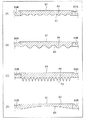
図7は、集塵ファン60の回収部81の変形例を示す図である。図7の(A)、(B)、(C)及び(D)に示すように、回収部81は、ケーシング62の背面板62Bとは別部材として、取外し可能にボルト(図示せず)などで固定するようにしてもよい。この場合、回収部81のみをケーシング62の背面板62Bから外向きに取り外し、回収面83に付着した溶媒23を除去することができる。このため、ケーシング62を分解する場合に比べて、集塵ファン60のメンテナンスが容易になる。
(Modification)
FIG. 7 is a view showing a modified example of the
回収部81は、回収面83側に表面積拡大部84を有してもよい。表面積拡大部84は、回収面83の表面積を拡大するために設けられる。図7の(A)では、表面積拡大部84は多数のディンプル形状を有している。図7の(B)では、表面積拡大部84は多数の凹凸形状を有している。図7の(C)では、表面積拡大部84は多数の針形状を有している。図7の(D)では、表面積拡大部84は1つの凹形状を有している。さらに、表面積拡大部84は、前記したディンプル形状、凹凸形状、凹形状、及び針形状を任意に組み合わせた形状でもよい。回収面83は、表面積拡大部84の表面に設けられる。表面積拡大部84を設けることにより回収面83の表面積が増大し、溶媒23を効率良く付着させることができる。尚、表面積拡大部84はこれらの形状に限定されない。表面積拡大部84の形状は、回収面83の表面積を拡大する形状であれば、任意の形状でもよい。
The
図8は、集塵ファン60の回収部81の別の変形例を示す図である。図8に示すように、回収部81の外面にヒートシンク85を設けてもよい。ヒートシンク85は、回収面83の放熱性を高めるために設けられる。ヒートシンク85を設けることにより回収面83を低温に保つことができ、回収面83に接触した溶媒23を液化させやすくなる。尚、ヒートシンク85と上述した表面積拡大部84とを組み合わせてもよい。
FIG. 8 is a view showing another modification of the
図9は、集塵ファン60の回収部81の別の変形例を示す図である。回収部81は、冷却部86及び温度制御部87を有してもよい。冷却部86は、回収面83を強制冷却する部分である。冷却部86は、例えば、送風ファンにより送風させること、又は、冷媒を循環させることにより、回収面83を強制冷却する機構を備えている。温度制御部87は、冷却部86の動作を制御して、回収面83の温度を制御する。温度制御部87は、回収面83の温度を検知するセンサ88を有している。温度制御部87は、センサ88からの検知信号に基づいて冷却部86の動作を制御して、回収面83の温度を制御する。この場合、回収面83をケーシング62の内部に送り込まれる排気雰囲気の温度よりも低温に確実に保つことができ、回収面83に接触した溶媒23を液化させやすくなる。尚、温度制御部87を設けずに、回収面83を強制冷却する冷却部86のみを設けてもよい。この場合、回収面83の温度を制御することはできないが、回収面83をケーシング62の内部に送り込まれる排気雰囲気の温度よりも低温にすることが可能になる。
FIG. 9 is a view showing another modified example of the
なお、本実施形態では、凝集部30、集塵部40、及び集塵ファン60を設けたが、溶媒の濃度又は必要とされる処理能力に応じて、溶媒分離システム100を集塵部40及び集塵ファン60で構成してもよい。また、溶媒分離システム100を凝集部30及び溶媒分離装置の一例としての集塵ファン60で構成してもよい。また、集塵ファン60のみで排気雰囲気22から溶媒23を除去するようにしてもよい。
In the present embodiment, although the
本実施形態では、集塵ファン60は1台としたが(図1参照)、複数台設置してもよい。例えば、図1において、第2排気ダクト12に複数台の集塵ファン60を並列に接続し、バルブによって排気雰囲気22を取り込む集塵ファン60を切り替えるようにしてもよい。この場合、集塵ファン60をメンテナンスする場合、バルブを操作することによりメンテナンス対象の集塵ファン60を排気経路から切り離し、メンテナンス対象外の別の集塵ファン60を作動させることができる。これにより、熱処理装置10及び溶媒分離システム100を停止させずに集塵ファン60のメンテナンスを行うことができる。
In the present embodiment, the
前記実施形態によれば、排気雰囲気から除去した溶媒を容易に回収することが可能となり、排気経路のメンテナンスを容易に行うことができる。 According to the embodiment, the solvent removed from the exhaust atmosphere can be easily recovered, and maintenance of the exhaust path can be easily performed.
以上、本発明の実施形態を説明したが、上述した実施形態は本発明を実施するための例示に過ぎない。よって、本発明は上述した実施形態に限定されることなく、その趣旨を逸脱しない範囲内で上述した実施形態を適宜変形して実施することが可能である。 While the embodiments of the present invention have been described above, the above-described embodiments are merely illustrative for carrying out the present invention. Therefore, the present invention is not limited to the embodiment described above, and the embodiment described above can be appropriately modified and implemented without departing from the scope of the invention.
なお、上記様々な実施形態又は変形例のうちの任意の実施形態又は変形例を適宜組み合わせることにより、それぞれの有する効果を奏するようにすることができる。また、実施形態同士の組み合わせ又は実施例同士の組み合わせ又は実施形態と実施例との組み合わせが可能であると共に、異なる実施形態又は実施例の中の特徴同士の組み合わせも可能である。 In addition, the effect which each has can be show | played by combining suitably the arbitrary embodiment or modification of said various embodiment or modification. Further, a combination of the embodiments or a combination of the embodiments or a combination of the embodiments and the embodiments is possible, and a combination of the features in different embodiments or the embodiments is also possible.
本発明の前記態様にかかる溶媒分離方法、溶媒分離装置及び溶媒分離システムは、排気雰囲気から除去した溶媒を容易に回収可能とし、排気経路のメンテナンスを容易に行うことができる。このため、溶媒分離方法、溶媒分離装置及び溶媒分離システムは、各種工業製品の製造工程又は各種電子部品の製造工程における乾燥炉、焼成炉、キュア炉、又はリフロー炉などの各種熱処理を行う熱処理装置などの排気発生装置に適用できる。 The solvent separation method, the solvent separation apparatus, and the solvent separation system according to the aspect of the present invention can easily recover the solvent removed from the exhaust atmosphere, and the maintenance of the exhaust path can be easily performed. Therefore, the solvent separation method, the solvent separation apparatus, and the solvent separation system are heat treatment apparatuses that perform various heat treatments such as a drying furnace, a baking furnace, a curing furnace, or a reflow furnace in the manufacturing process of various industrial products or the manufacturing process of various electronic components. It can be applied to exhaust gas generators such as
100 溶媒分離システム
10 熱処理装置
22 排気雰囲気
23 溶媒
30 凝集部
40 集塵部
60 集塵ファン(溶媒分離装置)
62 ケーシング
63 収容空間
64 取り入れ口
65 排出口
71 羽根車
72 羽根
75 回転軸
81 回収部
83 回収面
85 ヒートシンク
86 冷却部
87 温度制御部
100
62
Claims (18)
ケーシングの収容空間に収容された羽根車を回転させることにより、前記気化した溶媒を含んだ気体を前記ケーシングの取り入れ口から前記収容空間に取り入れる工程と、
前記収容空間に取り入れた前記気化した溶媒を、表面温度が前記気体の温度よりも低温となるように冷却された回収面で冷却して液化させることで、前記気体から前記溶媒を分離する工程とを含む、溶媒分離方法。 A solvent separation method for removing the solvent from a gas containing a vaporized solvent, the method comprising:
Introducing the gas containing the vaporized solvent from the intake of the casing into the accommodation space by rotating an impeller accommodated in the accommodation space of the casing;
Separating the solvent from the gas by cooling and liquefying the vaporized solvent taken into the storage space on a recovery surface cooled so that the surface temperature is lower than the temperature of the gas; Solvent separation method, including:
前記収容空間に面した回収面を有し、前記回収面の表面温度が、前記取り入れ口から取り入れられる気体の温度よりも低温となるように冷却される回収部と、を備え、
前記羽根車が回転することにより、気化した溶媒を含んだ気体を前記取り入れ口から前記収容空間に取り入れ、前記回収面で前記気化した溶媒を冷却し液化させることで、前記気体から前記溶媒を分離する溶媒分離装置。 A plurality of blades are arranged around the rotation axis, and the impeller has an impeller rotatable around the rotation axis, and a storage space for storing the impeller, an intake for introducing a gas into the storage space, and the gas A casing having a discharge port for discharging from the storage space;
And a recovery unit having a recovery surface facing the housing space, wherein a surface temperature of the recovery surface is cooled to a temperature lower than a temperature of a gas introduced from the inlet.
When the impeller rotates, a gas containing a vaporized solvent is taken into the storage space from the intake, and the vaporized solvent is cooled and liquefied on the recovery surface to separate the solvent from the gas Solvent separation equipment.
前記排気発生装置と前記溶媒分離装置の間に配置され、前記気化した溶媒を凝集させる凝集装置とを含む、溶媒分離システム。 The solvent separation device according to any one of claims 4 to 15 , which is disposed downstream of an exhaust gas generator for generating a gas containing a vaporized solvent.
A solvent separation system, comprising: an aggregation device disposed between the exhaust gas generator and the solvent separation device for aggregating the vaporized solvent.
Priority Applications (4)
| Application Number | Priority Date | Filing Date | Title |
|---|---|---|---|
| JP2016033508A JP6542693B2 (en) | 2016-02-24 | 2016-02-24 | Solvent separation method, solvent separation device and solvent separation system |
| US15/362,239 US10258995B2 (en) | 2016-02-24 | 2016-11-28 | Solvent separation method, solvent separation apparatus and solvent separation system |
| CN201611221825.1A CN107115689B (en) | 2016-02-24 | 2016-12-26 | Solvent fractionation method, solvent separation unit and solvent separation system |
| KR1020170010266A KR101867213B1 (en) | 2016-02-24 | 2017-01-23 | Solvent separation method, solvent separation apparatus and solvent separation system |
Applications Claiming Priority (1)
| Application Number | Priority Date | Filing Date | Title |
|---|---|---|---|
| JP2016033508A JP6542693B2 (en) | 2016-02-24 | 2016-02-24 | Solvent separation method, solvent separation device and solvent separation system |
Publications (2)
| Publication Number | Publication Date |
|---|---|
| JP2017148739A JP2017148739A (en) | 2017-08-31 |
| JP6542693B2 true JP6542693B2 (en) | 2019-07-10 |
Family
ID=59630619
Family Applications (1)
| Application Number | Title | Priority Date | Filing Date |
|---|---|---|---|
| JP2016033508A Active JP6542693B2 (en) | 2016-02-24 | 2016-02-24 | Solvent separation method, solvent separation device and solvent separation system |
Country Status (4)
| Country | Link |
|---|---|
| US (1) | US10258995B2 (en) |
| JP (1) | JP6542693B2 (en) |
| KR (1) | KR101867213B1 (en) |
| CN (1) | CN107115689B (en) |
Families Citing this family (1)
| Publication number | Priority date | Publication date | Assignee | Title |
|---|---|---|---|---|
| EP3473442B1 (en) * | 2017-10-20 | 2021-03-03 | CL Schutzrechtsverwaltungs GmbH | Apparatus for additively manufacturing of three-dimensional objects |
Family Cites Families (42)
| Publication number | Priority date | Publication date | Assignee | Title |
|---|---|---|---|---|
| NL166858C (en) * | 1969-05-24 | 1981-10-15 | Petersen Hugo Verfahrenstech | DEVICE FOR WET CLEANING OF A GAS POLLUTED WITH SUBSTANCES. |
| US3686893A (en) * | 1969-12-22 | 1972-08-29 | Purdue Research Foundation | Air refrigeration device |
| US3968649A (en) * | 1973-11-21 | 1976-07-13 | The Rovac Corporation | Exhaust emission control system |
| US3875268A (en) * | 1974-02-27 | 1975-04-01 | Gen Electric | Condenser apparatus |
| US4111615A (en) * | 1975-06-18 | 1978-09-05 | Matsushita Electric Industrial Company, Limited | Fluid exhausting device |
| US4292121A (en) * | 1979-09-21 | 1981-09-29 | The Caffes Trust | Solid/liquid separation through liquid vaporization and condensation, and apparatus therefor |
| US4316726A (en) | 1980-07-07 | 1982-02-23 | American Sterilizer Company | Method and apparatus for processing fluids |
| DE3528122A1 (en) * | 1985-08-06 | 1987-02-12 | Richard Scheuchl | PLANT FOR RECOVERING SOLVENTS FROM A PROCESS GAS FLOW |
| JPH0513363Y2 (en) | 1987-06-24 | 1993-04-08 | ||
| JPH0544223U (en) | 1991-11-25 | 1993-06-15 | 株式会社松井製作所 | Gas treatment equipment |
| US5277707A (en) * | 1992-07-16 | 1994-01-11 | Cool Fog Systems, Inc. | Air stream solvent vapor remover |
| US5580368A (en) * | 1995-02-22 | 1996-12-03 | Su-Ying R. Lu | Exhaust gas cleaning device |
| JPH08332302A (en) * | 1995-06-06 | 1996-12-17 | Seta Giken:Kk | Separation device and separation method |
| CN1092785C (en) * | 1995-07-28 | 2002-10-16 | 松下电器产业株式会社 | A connection method for a refrigeration system |
| JPH11300153A (en) * | 1998-04-24 | 1999-11-02 | Dainippon Screen Mfg Co Ltd | Sublimed component removing unit and heat treatment device provided with the same |
| US6638343B1 (en) * | 1998-12-01 | 2003-10-28 | Ebara Corporation | Exhaust gas treating device |
| JP2001070750A (en) * | 1999-09-06 | 2001-03-21 | Taikisha Ltd | Waste gas treatment system |
| JP4580590B2 (en) * | 2001-06-21 | 2010-11-17 | パナソニック株式会社 | Flux removal method and apparatus |
| US6619054B1 (en) | 2002-05-06 | 2003-09-16 | Hydrogenics Corporation | Condenser for dehumidifying gas |
| US6780225B2 (en) * | 2002-05-24 | 2004-08-24 | Vitronics Soltec, Inc. | Reflow oven gas management system and method |
| JP2004301373A (en) * | 2003-03-28 | 2004-10-28 | Ngk Insulators Ltd | Drying furnace |
| JP4022186B2 (en) * | 2003-09-04 | 2007-12-12 | 東京エレクトロン株式会社 | Vacuum drying device, vacuum drying method and collection device |
| US20050139073A1 (en) * | 2003-12-24 | 2005-06-30 | Rosen Eric B. | Emission control device and method of operation thereof |
| US20050142052A1 (en) * | 2003-12-24 | 2005-06-30 | Rosen Eric B. | Method and apparatus to remove particulates from a gas stream |
| FR2879942B1 (en) * | 2004-12-27 | 2007-01-26 | Commissariat Energie Atomique | DEVICE FOR PURIFYING A GAS STREAM CONTAINING CONDENSABLE VAPORS |
| CN100548555C (en) * | 2005-02-07 | 2009-10-14 | 千住金属工业株式会社 | Method for removing smoke from reflow furnace and reflow furnace |
| KR100614245B1 (en) * | 2005-03-21 | 2006-08-22 | 주식회사 동호에이텍 | Centrifugal Cooling Dust Collector for Dry Washing |
| SE528750C2 (en) * | 2005-06-27 | 2007-02-06 | 3Nine Ab | Method and apparatus for separating particles from a gas stream |
| KR20080005777A (en) * | 2006-07-10 | 2008-01-15 | 삼성전자주식회사 | Centrifugal Blower for Dehumidifier and Dehumidifier |
| US20100107687A1 (en) * | 2008-11-06 | 2010-05-06 | Diki Andrian | Process for removing gaseous contaminants from a feed gas stream comprising methane and gaseous contaminants |
| US20100319654A1 (en) * | 2009-06-17 | 2010-12-23 | Hans-Peter Messmer | Rotary vane engines and methods |
| US8584475B2 (en) * | 2009-06-30 | 2013-11-19 | George Scesney | Self-contained water generation system |
| US8596068B2 (en) * | 2009-10-30 | 2013-12-03 | Gilbert Staffend | High efficiency thermodynamic system |
| FR2952552B1 (en) * | 2009-11-19 | 2012-01-13 | Commissariat Energie Atomique | DEVICE FOR RECOVERING NANOPOUDERS AND ULTRAFINE POWDERS CONTAINED IN A GAS |
| JP5540680B2 (en) * | 2009-12-11 | 2014-07-02 | 千住金属工業株式会社 | Reflow furnace |
| JP2012005994A (en) * | 2010-06-28 | 2012-01-12 | Sozo Kagaku Kenkyusho:Kk | Method for condensation of hydrous liquid medium and condenser |
| JP5267889B2 (en) | 2010-08-10 | 2013-08-21 | 株式会社Aep | Atomizer recovery device |
| JP2014057935A (en) | 2012-09-19 | 2014-04-03 | Panasonic Corp | Exhaust purification method |
| US9593885B2 (en) | 2013-08-30 | 2017-03-14 | Advanced Analytical Solutions, Llc | Axial fan inlet wind-turning vane assembly |
| JP6103312B2 (en) * | 2013-11-06 | 2017-03-29 | パナソニックIpマネジメント株式会社 | Solvent separation method and apparatus |
| DE102014218344B4 (en) * | 2014-09-12 | 2023-08-03 | Dürr Systems Ag | Process and system for separating contaminants from process exhaust air |
| JP6268609B2 (en) * | 2015-04-24 | 2018-01-31 | パナソニックIpマネジメント株式会社 | Solvent separation apparatus and heat treatment apparatus |
-
2016
- 2016-02-24 JP JP2016033508A patent/JP6542693B2/en active Active
- 2016-11-28 US US15/362,239 patent/US10258995B2/en active Active
- 2016-12-26 CN CN201611221825.1A patent/CN107115689B/en active Active
-
2017
- 2017-01-23 KR KR1020170010266A patent/KR101867213B1/en active Active
Also Published As
| Publication number | Publication date |
|---|---|
| KR101867213B1 (en) | 2018-06-12 |
| CN107115689B (en) | 2019-05-14 |
| JP2017148739A (en) | 2017-08-31 |
| KR20170099758A (en) | 2017-09-01 |
| US20170239670A1 (en) | 2017-08-24 |
| US10258995B2 (en) | 2019-04-16 |
| CN107115689A (en) | 2017-09-01 |
Similar Documents
| Publication | Publication Date | Title |
|---|---|---|
| US10617974B2 (en) | Method and apparatus for extracting botanical oils | |
| KR102165974B1 (en) | Method and apparatus for separating solvent | |
| US20150354461A1 (en) | Engine systems and methods for removing particles from turbine air | |
| JP2014521496A5 (en) | ||
| US9199248B2 (en) | Aircraft electronic particle separation system | |
| KR101979496B1 (en) | Solvent separation method and solvent separation apparatus | |
| JP6542693B2 (en) | Solvent separation method, solvent separation device and solvent separation system | |
| WO2020090632A1 (en) | Vacuum pump, and vacuum pump constituent component | |
| US9216827B2 (en) | Self-contained aircraft electronic air treatment system | |
| US10040025B2 (en) | Solvent separator and heat treatment apparatus | |
| CN203852996U (en) | Device for recycling organic solvent during preparation of polyimide film | |
| SE512597C2 (en) | Drive system for a vehicle | |
| JP7447837B2 (en) | Painting exhaust treatment equipment and painting exhaust treatment method | |
| KR20230055061A (en) | Apparatus for sampling bio-aerosol in air with condenser | |
| AU2016362314B2 (en) | System, apparatuses, and methods for improving the operation of a turbine by using electrostatic precipitation | |
| Salazar et al. | Electrically enhanced condensation ii: Effects of the electrospray | |
| US20180106536A1 (en) | Dryer For Preparation of Dry Nanoparticles | |
| JP6398805B2 (en) | Continuous cooling device and cooling method for powder | |
| JP7380514B2 (en) | Deodorizing equipment and method for paint drying ovens | |
| JP2014057935A (en) | Exhaust purification method | |
| WO2024173351A1 (en) | Support systems for condensing systems | |
| JPH02298309A (en) | Clean air manufacturing device | |
| WO2014009839A2 (en) | A turbine cooling system |
Legal Events
| Date | Code | Title | Description |
|---|---|---|---|
| A621 | Written request for application examination |
Free format text: JAPANESE INTERMEDIATE CODE: A621 Effective date: 20170911 |
|
| A977 | Report on retrieval |
Free format text: JAPANESE INTERMEDIATE CODE: A971007 Effective date: 20181121 |
|
| A131 | Notification of reasons for refusal |
Free format text: JAPANESE INTERMEDIATE CODE: A131 Effective date: 20181204 |
|
| A521 | Request for written amendment filed |
Free format text: JAPANESE INTERMEDIATE CODE: A523 Effective date: 20190123 |
|
| TRDD | Decision of grant or rejection written | ||
| A01 | Written decision to grant a patent or to grant a registration (utility model) |
Free format text: JAPANESE INTERMEDIATE CODE: A01 Effective date: 20190611 |
|
| A61 | First payment of annual fees (during grant procedure) |
Free format text: JAPANESE INTERMEDIATE CODE: A61 Effective date: 20190613 |
|
| R151 | Written notification of patent or utility model registration |
Ref document number: 6542693 Country of ref document: JP Free format text: JAPANESE INTERMEDIATE CODE: R151 |