JP6513300B1 - IMAGE PROCESSING APPARATUS, IMAGE PROCESSING METHOD, AND IMAGE PROCESSING PROGRAM - Google Patents
IMAGE PROCESSING APPARATUS, IMAGE PROCESSING METHOD, AND IMAGE PROCESSING PROGRAM Download PDFInfo
- Publication number
- JP6513300B1 JP6513300B1 JP2018540890A JP2018540890A JP6513300B1 JP 6513300 B1 JP6513300 B1 JP 6513300B1 JP 2018540890 A JP2018540890 A JP 2018540890A JP 2018540890 A JP2018540890 A JP 2018540890A JP 6513300 B1 JP6513300 B1 JP 6513300B1
- Authority
- JP
- Japan
- Prior art keywords
- image
- image portion
- background
- foreground
- dimensional
- Prior art date
- Legal status (The legal status is an assumption and is not a legal conclusion. Google has not performed a legal analysis and makes no representation as to the accuracy of the status listed.)
- Active
Links
Images


Classifications
-
- G—PHYSICS
- G06—COMPUTING OR CALCULATING; COUNTING
- G06T—IMAGE DATA PROCESSING OR GENERATION, IN GENERAL
- G06T3/00—Geometric image transformations in the plane of the image
-
- G—PHYSICS
- G06—COMPUTING OR CALCULATING; COUNTING
- G06T—IMAGE DATA PROCESSING OR GENERATION, IN GENERAL
- G06T15/00—Three-dimensional [3D] image rendering
- G06T15/10—Geometric effects
- G06T15/20—Perspective computation
- G06T15/205—Image-based rendering
-
- B—PERFORMING OPERATIONS; TRANSPORTING
- B60—VEHICLES IN GENERAL
- B60R—VEHICLES, VEHICLE FITTINGS, OR VEHICLE PARTS, NOT OTHERWISE PROVIDED FOR
- B60R1/00—Optical viewing arrangements; Real-time viewing arrangements for drivers or passengers using optical image capturing systems, e.g. cameras or video systems specially adapted for use in or on vehicles
-
- G—PHYSICS
- G06—COMPUTING OR CALCULATING; COUNTING
- G06T—IMAGE DATA PROCESSING OR GENERATION, IN GENERAL
- G06T1/00—General purpose image data processing
-
- G—PHYSICS
- G06—COMPUTING OR CALCULATING; COUNTING
- G06T—IMAGE DATA PROCESSING OR GENERATION, IN GENERAL
- G06T15/00—Three-dimensional [3D] image rendering
- G06T15/04—Texture mapping
-
- G—PHYSICS
- G06—COMPUTING OR CALCULATING; COUNTING
- G06T—IMAGE DATA PROCESSING OR GENERATION, IN GENERAL
- G06T15/00—Three-dimensional [3D] image rendering
- G06T15/10—Geometric effects
- G06T15/20—Perspective computation
-
- G—PHYSICS
- G06—COMPUTING OR CALCULATING; COUNTING
- G06T—IMAGE DATA PROCESSING OR GENERATION, IN GENERAL
- G06T17/00—Three-dimensional [3D] modelling for computer graphics
- G06T17/10—Constructive solid geometry [CSG] using solid primitives, e.g. cylinders, cubes
-
- G—PHYSICS
- G06—COMPUTING OR CALCULATING; COUNTING
- G06T—IMAGE DATA PROCESSING OR GENERATION, IN GENERAL
- G06T19/00—Manipulating three-dimensional [3D] models or images for computer graphics
-
- G—PHYSICS
- G06—COMPUTING OR CALCULATING; COUNTING
- G06T—IMAGE DATA PROCESSING OR GENERATION, IN GENERAL
- G06T19/00—Manipulating three-dimensional [3D] models or images for computer graphics
- G06T19/006—Mixed reality
-
- G—PHYSICS
- G06—COMPUTING OR CALCULATING; COUNTING
- G06T—IMAGE DATA PROCESSING OR GENERATION, IN GENERAL
- G06T5/00—Image enhancement or restoration
- G06T5/50—Image enhancement or restoration using two or more images, e.g. averaging or subtraction
-
- G—PHYSICS
- G06—COMPUTING OR CALCULATING; COUNTING
- G06T—IMAGE DATA PROCESSING OR GENERATION, IN GENERAL
- G06T7/00—Image analysis
- G06T7/10—Segmentation; Edge detection
- G06T7/11—Region-based segmentation
-
- G—PHYSICS
- G06—COMPUTING OR CALCULATING; COUNTING
- G06T—IMAGE DATA PROCESSING OR GENERATION, IN GENERAL
- G06T7/00—Image analysis
- G06T7/10—Segmentation; Edge detection
- G06T7/174—Segmentation; Edge detection involving the use of two or more images
-
- G—PHYSICS
- G06—COMPUTING OR CALCULATING; COUNTING
- G06T—IMAGE DATA PROCESSING OR GENERATION, IN GENERAL
- G06T7/00—Image analysis
- G06T7/10—Segmentation; Edge detection
- G06T7/194—Segmentation; Edge detection involving foreground-background segmentation
-
- G—PHYSICS
- G06—COMPUTING OR CALCULATING; COUNTING
- G06T—IMAGE DATA PROCESSING OR GENERATION, IN GENERAL
- G06T7/00—Image analysis
- G06T7/70—Determining position or orientation of objects or cameras
-
- G—PHYSICS
- G06—COMPUTING OR CALCULATING; COUNTING
- G06T—IMAGE DATA PROCESSING OR GENERATION, IN GENERAL
- G06T7/00—Image analysis
- G06T7/97—Determining parameters from multiple pictures
-
- H—ELECTRICITY
- H04—ELECTRIC COMMUNICATION TECHNIQUE
- H04N—PICTORIAL COMMUNICATION, e.g. TELEVISION
- H04N23/00—Cameras or camera modules comprising electronic image sensors; Control thereof
- H04N23/60—Control of cameras or camera modules
-
- G—PHYSICS
- G06—COMPUTING OR CALCULATING; COUNTING
- G06T—IMAGE DATA PROCESSING OR GENERATION, IN GENERAL
- G06T2207/00—Indexing scheme for image analysis or image enhancement
- G06T2207/10—Image acquisition modality
- G06T2207/10004—Still image; Photographic image
- G06T2207/10012—Stereo images
-
- G—PHYSICS
- G06—COMPUTING OR CALCULATING; COUNTING
- G06T—IMAGE DATA PROCESSING OR GENERATION, IN GENERAL
- G06T2207/00—Indexing scheme for image analysis or image enhancement
- G06T2207/30—Subject of image; Context of image processing
- G06T2207/30248—Vehicle exterior or interior
- G06T2207/30252—Vehicle exterior; Vicinity of vehicle
- G06T2207/30261—Obstacle
-
- G—PHYSICS
- G06—COMPUTING OR CALCULATING; COUNTING
- G06T—IMAGE DATA PROCESSING OR GENERATION, IN GENERAL
- G06T2207/00—Indexing scheme for image analysis or image enhancement
- G06T2207/30—Subject of image; Context of image processing
- G06T2207/30248—Vehicle exterior or interior
- G06T2207/30252—Vehicle exterior; Vicinity of vehicle
- G06T2207/30264—Parking
-
- G—PHYSICS
- G06—COMPUTING OR CALCULATING; COUNTING
- G06T—IMAGE DATA PROCESSING OR GENERATION, IN GENERAL
- G06T3/00—Geometric image transformations in the plane of the image
- G06T3/40—Scaling of whole images or parts thereof, e.g. expanding or contracting
- G06T3/4038—Image mosaicing, e.g. composing plane images from plane sub-images
Landscapes
- Engineering & Computer Science (AREA)
- Physics & Mathematics (AREA)
- Theoretical Computer Science (AREA)
- General Physics & Mathematics (AREA)
- Computer Graphics (AREA)
- Computer Vision & Pattern Recognition (AREA)
- Geometry (AREA)
- Computing Systems (AREA)
- Software Systems (AREA)
- Multimedia (AREA)
- Computer Hardware Design (AREA)
- General Engineering & Computer Science (AREA)
- Signal Processing (AREA)
- Mechanical Engineering (AREA)
- Image Processing (AREA)
- Studio Devices (AREA)
- Processing Or Creating Images (AREA)
Abstract
画像処理装置(10)は、複数の撮像画像の各々を、実在する立体物である実在オブジェクトが占める前景画像部分とそれ以外の背景画像部分とに分割する画像分割部である立体物抽出部(1)と、参照画像部分を前景画像部分の領域に貼り付けることによって背景画像部分を補完する背景補完部(2)と、複数の補完された背景画像部分の視点位置を変更する俯瞰変換を行い、俯瞰変換された背景画像部分を合成することによって背景俯瞰合成画像を生成する背景画像合成部(3)と、実在オブジェクトの姿勢情報を取得する立体物認識部(4)と、姿勢情報を用いて実在オブジェクトに対応する3次元仮想オブジェクトを取得する立体物射影投影部(5)と、背景俯瞰合成画像に3次元仮想オブジェクトを重畳して3次元空間画像を生成する3次元空間重畳部(6)と、3次元空間画像を上から見た画像である俯瞰合成画像を生成して出力する表示画像出力部(7)とを有する。 The image processing apparatus (10) is a solid object extraction unit (image division unit) that divides each of a plurality of captured images into a foreground image portion occupied by a real object that is a solid object and a background image portion other than that. 1) and a background complementing unit (2) that complements the background image portion by pasting the reference image portion to the region of the foreground image portion, and performing a haze conversion that changes the viewpoint position of a plurality of complemented background image portions Using a background image combining unit (3) for generating a background / overlapping composite image by combining a background image portion subjected to overhead conversion, a solid object recognition unit (4) for acquiring orientation information of a real object, and orientation information Object projection and projection unit (5) for acquiring a three-dimensional virtual object corresponding to a real object, and a three-dimensional space image by superimposing That has three-dimensional space superimposing unit (6), the display image output unit for generating and outputting bird's-eye synthesized image is an image viewed from above the three-dimensional image and (7).
Description
本発明は、複数の撮像画像から俯瞰合成画像を生成する画像処理装置、並びに複数の撮像画像から俯瞰合成画像を生成するために使用される画像処理方法及び画像処理プログラムに関する。 The present invention relates to an image processing apparatus that generates an overhead synthetic image from a plurality of captured images, and an image processing method and an image processing program used to generate an overhead synthetic image from a plurality of captured images.
複数のカメラで得られた複数の撮像画像を視点変換して複数の俯瞰画像を生成し、複数の俯瞰画像を合成して俯瞰合成画像を生成する技術がある。特許文献1は、2つの撮像画像の共通の撮像領域を区分する境界位置と共通の撮像領域内の立体物の位置とに基づいて視点変換された2つの俯瞰画像のうちの、立体物の画像の歪みが小さい俯瞰画像を選択し、選択された俯瞰画像を用いて俯瞰合成画像を生成する技術を記載している。 There is a technique of generating viewpoint images by converting a plurality of captured images obtained by a plurality of cameras to generate a plurality of overhead images, and combining a plurality of overhead images to generate an overhead synthetic image. Patent document 1 is an image of a three-dimensional object of two overhead images obtained by viewpoint conversion based on a boundary position dividing a common imaging region of two captured images and a position of a three-dimensional object in the common imaging region. A technique is described that selects a bird's-eye view image with low distortion and generates a bird's-eye view composite image using the selected bird's-eye view image.
上記従来の技術では、立体物の画像の歪みが小さい俯瞰画像を用いて俯瞰合成画像を生成するが、立体物に歪みがあり、見る者に違和感を与える場合がある。 In the above-mentioned prior art, although a bird's-eye view composite image is generated using a bird's-eye view image with small distortion of the image of a three-dimensional object, the three-dimensional object has distortion, which may make the viewer uncomfortable.
本発明は、上記課題を解決するためになされたものであり、見る者に違和感を与えにくい俯瞰合成画像を生成することができる画像処理装置、並びに見る者に違和感を与えにくい俯瞰合成画像を生成するために使用される画像処理方法及び画像処理プログラムを提供することを目的とする。 The present invention has been made to solve the above problems, and an image processing apparatus capable of generating a synthetic image that is unlikely to give a sense of discomfort to a viewer, and a synthetic image of a shade that does not give a sense of discomfort to a viewer Image processing method and image processing program used to
本発明の一態様に係る画像処理装置は、撮影対象領域を撮影する第1の撮像装置から提供される第1の撮像画像を、前記撮影対象領域内に実在する立体物である実在オブジェクトが占める第1の前景画像部分と前記第1の前景画像部分以外の第1の背景画像部分とに分割し、前記撮影対象領域を撮影する第2の撮像装置から提供される第2の撮像画像を、前記撮影対象領域内に実在する前記立体物である実在オブジェクトが占める第2の前景画像部分と前記第2の前景画像部分以外の第2の背景画像部分とに分割する画像分割部と、予め取得されている参照画像の一部である参照画像部分を前記第1の前景画像部分の領域に貼り付けることによって前記第1の背景画像部分を補完して、補完された第1の背景画像部分を生成し、前記参照画像部分を前記第2の前景画像部分の領域に貼り付けることによって前記第2の背景画像部分を補完して、補完された第2の背景画像部分を生成する背景補完部と、前記補完された第1の背景画像部分の視点位置と前記補完された第2の背景画像部分の視点位置とを変更する俯瞰変換を行い、俯瞰変換された前記第1の背景画像部分と俯瞰変換された前記第2の背景画像部分とを合成することによって背景俯瞰合成画像を生成する背景画像合成部と、前記実在オブジェクトを認識し、前記実在オブジェクトの姿勢情報を取得する立体物認識部と、前記姿勢情報を用いて、前記実在オブジェクトに対応する3次元仮想オブジェクトを取得し、前記3次元仮想オブジェクトに前記第1の前景画像部分又は前記第2の前景画像部分である前景画像部分を射影投影し、前記前景画像部分が射影投影されている前記3次元仮想オブジェクトを生成する立体物射影投影部と、前記背景俯瞰合成画像に前記前景画像部分が射影投影されている前記3次元仮想オブジェクトを重畳して3次元空間画像を生成する3次元空間重畳部と、前記3次元空間画像を上から見た画像である俯瞰合成画像を生成して出力する表示画像出力部と、を有することを特徴とする。 The image processing apparatus according to an embodiment of the present invention, the first captured image provided from the first imaging device for photographing a photographing target area, the real object is a solid object which actually exists in the shooting target area the first is divided into a front image part and the first background image portion other than the first foreground image portion, the second captured image supplied from the second imaging device for imaging the imaging target region occupied An image dividing unit configured to divide in advance a second foreground image portion occupied by the real object which is the three-dimensional object existing in the photographing target area and a second background image portion other than the second foreground image portion ; a reference image portion which is a part of the reference image being obtained by complementing the first background image portion by attaching to the region of the first foreground image portion, the first background image complements generates a portion, said reference image It complements the second background image portion by attaching a minute area of the second foreground image portion, the background complement unit that generates a second background image portion complemented were the complements The eyelid transformation is performed to change the eyepoint position of the first background image portion and the eyepoint position of the second background image portion that has been complemented , and the eyelet transformed first eye portion with the first background image portion A background image combining unit that generates a background / 俯瞰 composite image by combining the two background image portions; a solid object recognition unit that recognizes the real object and acquires posture information of the real object; using the three-dimensional acquires a virtual object, the first foreground image portion or the front image part is a second front image part to the three-dimensional virtual object corresponding to the real object A three-dimensional object projection / projecting unit that generates a three-dimensional virtual object by performing shadow projection and projection projection of the foreground image portion; and the three-dimensional virtual object projection projection of the foreground image portion on the background / 俯瞰 composite image Having a three-dimensional space superimposing unit that generates a three-dimensional space image by superimposing the three-dimensional space image, and a display image output unit that It features.
本発明の他の態様に係る画像処理方法は、撮影対象領域を撮影する第1の撮像装置から提供される第1の撮像画像を、前記撮影対象領域内に実在する立体物である実在オブジェクトが占める第1の前景画像部分と前記第1の前景画像部分以外の第1の背景画像部分とに分割し、前記撮影対象領域を撮影する第2の撮像装置から提供される第2の撮像画像を、前記撮影対象領域内に実在する前記立体物である実在オブジェクトが占める第2の前景画像部分と前記第2の前景画像部分以外の第2の背景画像部分とに分割するステップと、予め取得されている参照画像の一部である参照画像部分を前記第1の前景画像部分の領域に貼り付けることによって前記第1の背景画像部分を補完して、補完された第1の背景画像部分を生成し、前記参照画像部分を前記第2の前景画像部分の領域に貼り付けることによって前記第2の背景画像部分を補完して、補完された第2の背景画像部分を生成するステップと、前記補完された第1の背景画像部分の視点位置と前記補完された第2の背景画像部分の視点位置とを変更する俯瞰変換を行い、俯瞰変換された前記第1の背景画像部分と俯瞰変換された前記第2の背景画像部分とを合成することによって背景俯瞰合成画像を生成するステップと、前記実在オブジェクトを認識し、前記実在オブジェクトの姿勢情報を取得するステップと、前記姿勢情報を用いて、前記実在オブジェクトに対応する3次元仮想オブジェクトを取得し、前記3次元仮想オブジェクトに前記第1の前景画像部分又は前記第2の前景画像部分である前景画像部分を射影投影し、前記前景画像部分が射影投影されている前記3次元仮想オブジェクトを生成するステップと、前記背景俯瞰合成画像に前記前景画像部分が射影投影されている前記3次元仮想オブジェクトを重畳して3次元空間画像を生成するステップと、前記3次元空間画像を上から見た画像である俯瞰合成画像を生成して出力するステップと、を有することを特徴とする。 Image processing method according to another aspect of the present invention, real object is a solid object which the first captured image provided from the first imaging device for photographing a photographing target area, actually exists in the shooting target area first divided into a front image part and the first background image portion other than the first foreground image portion, the second captured image supplied from the second imaging device for imaging the imaging target region occupies Dividing into a second foreground image portion occupied by the real object which is the solid object existing in the photographing target area and a second background image portion other than the second foreground image portion; It complements the first background image portion by attaching the reference image portion which is a part of the reference image being the area of the first foreground image portion, the first background image portion complements It generates the reference image It complements the second background image portion by attaching a minute area of the second foreground image portion, and generating a second background image portion is complemented, first, which is the complement background image portion of the viewpoint position and performs overview transformation for changing the viewpoint position of the complemented second background image portion, overhead converted first background image portion and overhead converted the second of The step of generating a background / 俯瞰 synthetic image by combining with a background image portion, the step of recognizing the real object, the step of acquiring posture information of the real object, and using the posture information to correspond to the real object get the 3-dimensional virtual object, the first foreground image portion or front image part is the second foreground image portions projected projected onto the 3-dimensional virtual object, Generating the three-dimensional virtual object in which the foreground image portion is project-projected; and superimposing the three-dimensional virtual object in which the foreground image portion is project-projected on the background / 俯瞰 composite image to form a three-dimensional space image And generating and outputting an overhead synthetic image which is an image of the three-dimensional space image viewed from above.
本発明によれば、複数の撮像画像から見る者に違和感を与えにくい俯瞰合成画像を生成することができる。 According to the present invention, it is possible to generate a bird's-eye synthetic image that is less likely to give a sense of incongruity to a viewer from a plurality of captured images.
以下に、本発明の実施の形態に係る画像処理装置、画像処理方法、及び画像処理プログラムを、添付図面を参照しながら説明する。以下の実施の形態は、例にすぎず、本発明の範囲内で種々の変更が可能である。 Hereinafter, an image processing apparatus, an image processing method, and an image processing program according to an embodiment of the present invention will be described with reference to the attached drawings. The following embodiments are merely examples, and various modifications are possible within the scope of the present invention.
《1》構成
《1−1》ハードウェア構成
図1は、本発明の実施の形態に係る画像処理装置10のハードウェア構成を示す図である。画像処理装置10は、本実施の形態に係る画像処理方法を実施することができる装置である。画像処理装置10は、例えば、コンピュータである。図1に示されるように、画像処理装置10は、情報処理部であるプロセッサ11と、メモリ12と、記憶装置13と、撮像画像データ(単に「撮像画像」とも言う)を受け取る画像入力インタフェース14と、表示画像データを出力する表示機器インタフェース15とを有する。メモリ12と記憶装置13とは、記憶部16とも称される。<< 1 >> Configuration << 1-1 >> Hardware Configuration FIG. 1 is a diagram showing a hardware configuration of the
プロセッサ11は、各種の演算処理及びハードウェアに対する各種の制御処理を行う。メモリ12は、主記憶装置である。メモリ12は、例えば、RAM(Random Access Memory)である。記憶装置13は、補助記憶装置である。記憶装置13は、例えば、ハードディスク装置又はSSD(Solid State Drive)である。画像入力インタフェース14は、複数の撮像装置から提供される複数の映像信号、すなわち、複数の撮像画像を画像処理装置10に取り込むための装置である。表示機器インタフェース15は、表示画像をディスプレイなどの表示機器に送信するための装置である。
The
図1の例では、画像処理装置10に2台の撮像装置20a及び20bが接続されている。ただし、画像処理装置10に接続される撮像装置の台数は、3台以上であってもよい。撮像装置20a及び20bの各々は、画像を撮影する機能を持つ。撮像装置20a及び20bの各々は、CCD(Charged−Coupled Device)又はCMOS(Complementary Metal−Oxide−Semiconductor)のような撮像素子とレンズとを備えたカメラ機器(単に「カメラ」とも言う)である。撮像装置20a及び20bは、互いに同様の構造を持つカメラ機器であることが望ましい。撮像装置20aは、第1の撮像対象領域を撮像する。撮像装置20bは、第2の撮像対象領域を撮像する。第1の撮像対象領域と第2の撮像対象領域とは、部分的に重複しており、共通の撮像対象領域部分を有する。
In the example of FIG. 1, two
撮像装置20a及び20bは、画像処理装置10の画像入力インタフェース14と有線で接続されてもよく、又は、無線で接続されてもよい。撮像装置20a及び20bと画像入力インタフェース14とは、例えば、IP(Internet Protocol)ネットワークを介して又は同軸ケーブルを介して通信する。撮像装置20a及び20bと画像入力インタフェース14との間の接続方式及び通信方式は、特定の方式に限定されない。画像入力インタフェース14は、撮像装置20a及び20bから提供される2つの(すなわち、2画面の)撮像画像100a及び100bを同時に(すなわち、並列的に)受信する機能を持つ。
The
撮像装置20a及び20bから提供される2つの撮像画像100a及び100bは、画像入力インタフェース14を介して画像処理装置10の内部に取り込まれ、メモリ12に記憶される。画像処理装置10に取り込まれた2つの撮像画像100a及び100bは、撮像対象領域の各々の上方に視点を設けた画像である2つの俯瞰画像データ(単に「俯瞰画像」とも言う)に変換され、その後、2つの俯瞰画像は合成される。俯瞰画像を生成するための変換処理は「視点変換処理」である。本実施の形態では、俯瞰画像を生成するための視点変換処理を「俯瞰変換処理」と言う。プロセッサ11は、メモリ12又は記憶装置13に記憶されている画像処理プログラムを読み出して実行することで、視点変換処理及び合成処理を行う。視点変換処理及び合成処理によって生成された俯瞰合成画像データ(単に「俯瞰合成画像」とも言う)である表示画像データ(単に「表示画像」とも言う)は、表示機器インタフェース15を介してディスプレイなどの表示機器へ送信される。
The two captured
《1−2》機能構成
図2は、本実施の形態に係る画像処理装置10を示す機能ブロック図である。画像処理装置10は、撮像装置20a及び20bから撮像画像100a及び100bをそれぞれ受け取り、撮像対象領域における俯瞰画像から生成された俯瞰合成画像を表示画像として出力する。画像処理装置10は、撮像画像100a及び100bの各々から実在する対象物である立体物(「実在オブジェクト」とも言う)を抽出することによって、撮像画像100a及び100bの各々を前景画像部分データ(「前景画像部分」とも言う)と背景画像部分データ(「背景画像部分」とも言う)とに分割する画像分割部としての立体物抽出部1を有する。<< 1-2 >> Functional Configuration FIG. 2 is a functional block diagram showing an
また、画像処理装置10は、撮像画像100a及び100bの各々における立体物が抽出された領域に対して過去に取得した撮像画像100a及び100b(「参照画像データ」又は「参照画像」とも言う)の背景画像部分の一部を貼りつける背景補完部2を有する。参照画像の背景画像部分は、「参照画像部分データ」又は「参照画像部分」とも称される。また、画像処理装置10は、撮像画像100aの背景画像部分と撮像画像100bの背景画像部分とを合成する背景画像合成部3を有する。
In addition, the
さらに、画像処理装置10は、前景画像部分として抽出された立体物である実在オブジェクトを認識する立体物認識部4と、抽出された実在オブジェクトが占める前景画像部分に対応する(すなわち、立体物に対応する)選択された3次元仮想オブジェクトに射影投影する立体物射影投影部5とを有する。3次元仮想オブジェクトは、例えば、予め記憶部16に格納されている仮想的な立体物を表示させるための3次元画像データ又は立体物に対応する大きさを持つ仮想的な立体物を表示させるように生成された3次元画像データである。
Furthermore, the
また、画像処理装置10は、背景画像合成部3によって仮想的な3次元空間に形成された背景画像部分上に、3次元仮想オブジェクトを配置する(すなわち、重ねる)3次元空間重畳部6と、背景画像部分に3次元仮想オブジェクトを重畳することで形成された俯瞰合成画像を表示画像として出力する表示画像出力部7とを有する。
Further, the
《1−3》構成例
図3は、本実施の形態に係る画像処理装置10と2台の撮像装置20a及び20bと表示機器30とを含む画像処理システムの構成例を概略的に示す図である。<< 1-3 >> Configuration Example FIG. 3 schematically shows a configuration example of an image processing system including the
立体物抽出部1は、撮像画像100a及び100bの各々から実在する立体物である実在オブジェクト40を検出し、撮像画像における実在オブジェクト40に対応する部分である前景画像部分を抽出することによって、撮像画像100a及び100bの各々を前景画像部分と背景画像部分とに分割する。実在オブジェクト40は、例えば、人物、車両、生産物などである。立体物抽出部1は、実在オブジェクト40を検出し、検出された実在オブジェクト40を前景画像部分とし、前景画像部分以外の部分を背景画像部分とすることによって、撮像画像100a及び100bの各々を前景画像部分と背景画像部分とに分割する。撮像画像100aの背景画像部分は、撮像画像100aから立体物である実在オブジェクト40の領域を抜いた画像部分である。撮像画像100bの背景画像部分は、撮像画像100bから立体物である実在オブジェクト40の領域を抜いた画像部分である。立体物抽出部1が行う処理は、後述の図4、図5(a)及び(b)を用いて詳述される。
The three-dimensional object extraction unit 1 detects an
背景補完部2は、過去の撮像画像(例えば、同じ撮像装置によって撮影された画像)として記憶部16に記憶されている参照画像から、実在オブジェクト40の領域である前景画像部分を抜き取り、抜き取られた前景画像部分の代わりに参照画像の一部である参照画像部分を貼り付けることによって、前景画像部分が欠落している背景画像部分を補完する。これにより、実在オブジェクト40の領域を参照画像の一部によって補完した(すなわち、不足箇所の画像データを参照画像部分データで補った)背景画像部分が生成される。背景補完部2が行う処理は、後述の図6、図7(a)から(e)を用いて詳述される。
The background complement unit 2 extracts and extracts a foreground image portion which is a region of the
背景画像合成部3は、背景補完部2で補完された2つの背景画像部分から、背景俯瞰合成画像302を生成する。背景俯瞰合成画像302を生成するためには、事前に撮像装置20a及び20bの各々のキャリブレーションが行われており、撮像装置20a及び20bの各々の内部パラメータと外部パラメータと画像処理装置10によって取得されていることが前提になる。内部パラメータは、撮像装置20a及び20bの各々の焦点距離、光軸中心の位置及び方向などを示す情報を含む。外部パラメータは、撮像装置20a及び20bの各々の位置と姿勢であるカメラ位置姿勢を示す情報であり、撮像対象となる空間における設置位置(設置座標)情報と設置姿勢情報(例えば、ヨー、ロール、ピッチ情報)などを含む。背景画像合成部3は、背景補完部2で補完された2つの背景画像部分と、2つの背景画像部分と俯瞰合成画像との対応関係を示すピクセルデータからなる参照テーブルとを用いて俯瞰変換処理と合成処理とを行う。背景画像合成部3が行う処理は、後述の図8、図9(a)から(c)を用いて詳述される。
The background image combining unit 3 generates a background / overlapping combined
立体物認識部4は、先ず、撮像画像100aから抽出された前景画像部分と撮像画像100bから抽出された前景画像部分とから、立体物である実在オブジェクト40の認識を行う。実在オブジェクト40は、例えば、人物、車両、生産物などである。ただし、実在オブジェクト40は人物、車両、生産物に限定されない。次に、立体物認識部4は、撮像画像100aから抽出された前景画像部分と撮像画像100bから抽出された前景画像部分とから、実在オブジェクト40の姿勢情報を取得して、実在オブジェクト40の識別情報である実在オブジェクトID(識別子)、実在オブジェクト40の種類を示す実在オブジェクト種別、実在オブジェクト40の姿勢情報を記憶部16(例えば、メモリ12)に記憶させる。実在オブジェクト40の姿勢情報は、例えば、撮像画像100aから抽出された前景画像部分及び撮像画像100bから抽出された前景画像部分である2次元座標のピクセルデータを、3次元座標のピクセルデータに変換する際に使用されるテーブルである。実在オブジェクト40の姿勢情報は、前景画像部分における画像解析により求めてもよいし、撮像装置20a及び20bとは別の装置であるセンサーを用いて取得してもよい。実在オブジェクト40の姿勢情報の取得方法は、特定のものに限定されない。立体物認識部4が行う処理は、後述の図10を用いて詳述される。
The three-dimensional object recognition unit 4 first recognizes the
立体物射影投影部5は、立体物認識部4で認識された実在オブジェクト40に対応する3次元仮想オブジェクト400を取得する。3次元仮想オブジェクト400は、予め記憶部16に記憶されている複数の3次元仮想オブジェクトの中から、実在オブジェクト40に応じて選択されたものであってもよいし、姿勢情報を用いて生成されたものであってもよい。例えば、実在オブジェクト40が人物である場合には、人物を示す形状の3次元仮想オブジェクトが用いられる。また、実在オブジェクト40が動物である場合には、動物を示す形状の3次元仮想オブジェクトが用いられる。次に、立体物射影投影部5は、立体物抽出部1で撮像画像100aから抽出された前景画像部分及び撮像画像100bから抽出された前景画像部分に対応する3次元仮想オブジェクトに対して射影投影を行うことで、射影投影された3次元仮想オブジェクト400を生成する。具体的には、立体物射影投影部5は、背景俯瞰合成画像302における実在オブジェクト40としての人物を抽出した位置に、人物を上から見た形状に対応する形状を持つ3次元仮想オブジェクト400の画像を重畳表示させる。立体物射影投影部5が行う処理は、後述の図11及び図12を用いて詳述される。
The three-dimensional object projection and
3次元空間重畳部6は、例えば、XYZ直交座標系で示される3次元空間におけるZ=0の面に、背景画像合成部3で2つの補完された背景画像部分から生成された背景俯瞰合成画像302を配置し、前景画像部分の位置座標に射影投影された3次元仮想オブジェクト400を配置する。3次元空間重畳部6が行う処理は、後述の図13及び図14を用いて詳述される。
The three-dimensional space superimposing unit 6 is, for example, a background / tongue composite image generated from the two background image portions complemented by the background image combining unit 3 on the Z = 0 plane in the three-dimensional space indicated by the XYZ orthogonal coordinate system. 302 is arranged, and the three-dimensional
表示画像出力部7は、背景俯瞰合成画像302上に3次元仮想オブジェクト400が重畳された3次元空間の俯瞰合成画像を表示画像として表示機器30に出力する。表示画像出力部7が行う処理は、後述の図15を用いて詳述される。
The display
《2》動作
《2−1》立体物抽出部1
図4は、画像処理装置10の立体物抽出部1が行う処理を示すフローチャートである。図5(a)は、立体物抽出部1によって撮像画像100aから抽出された前景画像部分200a及び201a、背景画像部分300a、並びに前景画像撮影情報500a及び501aの例を示す説明図である。図5(b)は、立体物抽出部1によって撮像画像100bから抽出された前景画像部分200b及び201b、背景画像部分300b、並びに前景画像撮影情報500b及び501bの例を示す説明図である。図5(a)及び(b)には、1つの撮像画像から2つの前景画像部分と、2つの前景画像撮影情報とが抽出された例を示しているが、前景画像部分の数は2つに限定されず、前景画像撮影情報の数も2つに限定されない。<< 2 >> Operation << 2-1 >> Solid Object Extraction Unit 1
FIG. 4 is a flowchart showing processing performed by the three-dimensional object extraction unit 1 of the
前景画像撮影情報は、例えば、実在オブジェクト40における撮像装置20a及び20bに最も近い部分の位置座標、前景画像部分の解像度、実在オブジェクト40の大きさなどを含む。実在オブジェクト40の大きさは、例えば、実在オブジェクト40を矩形で囲んだ(例えば、外接するように囲んだ)際の、矩形の4つの頂点の座標で表わされる。ただし、実在オブジェクト40の大きさを表す情報は、矩形の4つの頂点の座標以外の情報指標であってもよい。
The foreground image photographing information includes, for example, position coordinates of a portion closest to the
先ず、立体物抽出部1は、複数の撮像画像100a及び100bを取得する(ステップS10)。撮像画像100a及び100bが圧縮符号化されている場合、立体物抽出部1は、撮像画像100a及び100bをデコードすることで、撮像画像100a及び100bに対応するRAW画像データを取得する。例えば、撮像装置20a及び20bから動画圧縮規格であるH.264形式で圧縮符号化された映像がストリーミング配信されている場合、立体物抽出部1は、撮像画像100a及び100bに対しH.264形式に対応するデコードを行うことで、RGBA(Red Green Blue Alpha)32ビットのRAW画像データを取得する。ただし、立体物抽出部1が取得する画像データの形式は、RGBA32ビットのRAW画像データに限定されない。
First, the three-dimensional object extraction unit 1 acquires a plurality of captured
次に、立体物抽出部1は、取得したRAW画像データから人物、車両、生産物などのような立体物である1つ以上の実在オブジェクト40を検出する(ステップS11)。実在オブジェクト40は、例えば、歩行する人物、走行する車両、工場の生産ラインにおける生産物などである。ただし、実在オブジェクト40は、これらに限定されず、動物、建造物、障害物、工場設備、ロボットなどのような他の立体物であってもよい。
Next, the three-dimensional object extraction unit 1 detects one or more
次に、立体物抽出部1は、RAW画像データから、検出され実在オブジェクト40を抽出し、RAW画像データを、実在オブジェクト40が撮像された領域部分である前景画像部分と、それ以外の領域部分である背景画像部分とに分割する(ステップS12)。実在オブジェクト40の抽出は、例えば、グラフカットと呼ばれる画像の領域抽出のための画像セグメンテ−ション技術を用いて行われる。立体物抽出部1は、グラフカットを用いることによって、撮像画像100a及び100bの各々から背景画像部分と前景画像部分とを分割することができる。ただし、実在オブジェクト40の抽出方法は、グラフカットを用いた方法に限定されない。例えば、実在オブジェクトの抽出に、ディープラーニングを用いた学習ベースの画像セグメンテーション技術(例えば、Open Pose)を用いてもよい。実在オブジェクト40に関する前景画像撮影情報は、例えば、撮像画像における前景画像部分の位置座標、前景画像部分の大きさを表す値、実在オブジェクト40を識別する識別子を含む。撮像画像100a及び100bから対象となる実在オブジェクト40が、0個又は1個以上抽出される。このため、実在オブジェクト40の検出から実在オブジェクト40の抽出までの処理(ステップS11及びS12)は、処理対象の撮像画像の数と同じ回数繰り返される。
Next, the three-dimensional object extraction unit 1 extracts the detected
次に、立体物抽出部1は、抽出された実在オブジェクト40に対して、実在オブジェクト40の同定を行う(ステップS13)。撮像装置20aの撮像対象領域と撮像装置20bの撮像対象領域とが共通の撮像対象領域部分を含む場合、撮像画像100a及び100bは、同じ実在オブジェクト40を撮影する場合がある。立体物抽出部1は、複数の実在オブジェクトの各々を識別するための識別子を実在オブジェクトの各々に付与する。撮像画像100aに含まれる実在オブジェクトと撮像画像100bに含まれる実在オブジェクトとが同じ実在オブジェクトである場合、立体物抽出部1は、この実在オブジェクトに同じ識別子を付与する。例えば、立体物抽出部1は、図5(a)及び(b)に示されるように、4枚の前景画像部分200a、201a、200b及び201bを検出し、前景画像部分201aと前景画像部分201bが同一であると判断した場合には、実際の実在オブジェクトの個数は3個であると判定する。立体物抽出部1は、撮像画像100a及び100bを入力として受け取り、背景画像部分300a及び300b、前景画像部分200a、201a、200b及び201b、前景画像撮影情報500a、501a、500b及び501bを出力する。
Next, the three-dimensional object extraction unit 1 identifies the existing
《2−2》背景補完部2
図6は、画像処理装置10の背景補完部2が行う処理を示すフローチャートである。背景補完部2は、予め記憶部16に記憶されている参照画像を用いて背景補完を行う(ステップS20)。背景補完部2は、対象となる前景画像部分200a、201a、200b及び201bに対応する前景画像撮影情報500a、501a、500b及び501bを用いて、背景補完を行う。背景補完部2は、実在オブジェクト40の前景画像部分200a、201a、200b及び201bの位置座標及び大きさを基に、参照画像から、前景画像部分200a、201a、200b及び201bの位置座標及び大きさと同じ位置座標及び大きさの参照画像部分を取得し、この参照画像部分を背景画像部分に貼りつけることで、前景画像部分の抜けを補完して、補完された背景画像部分を生成する。<< 2-2 >> Background complement unit 2
FIG. 6 is a flowchart showing processing performed by the background complementing unit 2 of the
図7(a)から(e)は、背景補完部2が行う処理を示す説明図である。例えば、背景補完部2は、図7(a)に示される撮像画像100aから抽出された図7(b)に示される対象となる前景画像部分200aを除いて得られた、図7(c)に示される背景画像部分300aを受け取る。次に、背景補完部2は、前景画像部分200aに関する前景画像撮影情報500aを用いて、対象物としての実在オブジェクトの前景画像部分200aの位置座標及び大きさを基に、図7(d)に示される参照画像350から、対象物としての実在オブジェクトの前景画像部分200aの位置座標及び大きさと同じ位置座標及び大きさの参照画像部分350aを取得する。次に、背景補完部2は、背景画像部分300aに参照画像部分350aを貼りつけることによって背景画像部分300aを補完し、図7(e)に示されるような補完された背景画像部分301aを生成する。つまり、背景補完部2は、前景画像部分200aを抜いた背景画像部分300aを入力として受け取り、参照画像350を用いて背景補完した背景画像部分301aを出力する。
FIGS. 7A to 7E are explanatory diagrams showing the process performed by the background complementing unit 2. For example, the background complement unit 2 is obtained by excluding the target foreground image portion 200a shown in FIG. 7B extracted from the captured
《2−3》背景画像合成部3
図8は、画像処理装置10の背景画像合成部3が行う処理を示すフローチャートである。背景画像合成部3は、背景補完部2における背景補完が行われた背景画像部分301a及び301bを入力として受け取り、背景画像部分301a及び301bを俯瞰変換(視点変換)し、俯瞰変換された背景画像部分を合成することで背景俯瞰合成画像302を生成する。<< 2-3 >> Background image combining unit 3
FIG. 8 is a flowchart showing processing performed by the background image combining unit 3 of the
具体的には、背景画像合成部3は、背景補完が行われた背景画像部分301a及び301bに対して撮像装置20aのレンズの特性によって生じる歪み及び撮像装置20bのレンズの特性によって生じる歪みを補正するための歪み補正処理を行う(ステップS30)。
Specifically, the background image combining unit 3 corrects distortion caused by the characteristics of the lens of the
次に、背景画像合成部3は、撮像装置20aの外部パラメータを用いて、背景補完が行われた背景画像部分301aを上(例えば、真上から)から見たように視点位置を変換する俯瞰変換を行う(ステップS31)。また、背景画像合成部3は、撮像装置20bの外部パラメータを用いて、背景補完が行われた背景画像部分301bを上(例えば、真上から)から見たように視点位置を変換する俯瞰変換を行う(ステップS31)。
Next, the background image combining unit 3 converts the viewpoint position as viewed from above (for example, from above) using the external parameters of the
次に、背景画像合成部3は、それぞれの俯瞰変換後の背景画像部分301a及び301bを合成する(ステップS32)。 Next, the background image combining unit 3 combines the background image portions 301a and 301b after the overhead conversion (step S32).
次に、背景画像合成部3は、俯瞰変換後の背景画像部分301a及び301bが重なり合う領域に対してアルファブレンドを行う(ステップS33)。アルファブレンドは、2つの画像を重ね合わせ、画素ごとに設定された係数である透明度(α値)に基いて合成する画像合成方法である。α値は、概念としては、透明度0%の完全不透明状態から透明度100%の完全透明状態までの透明度を表す。例えば、α値は、0から1までの範囲の値を取る係数であり、最小値(値0)の場合には透明度が最大であり、最大値(値1)の場合には不透明度が最大(塗りつぶし)になる。 Next, the background image combining unit 3 performs alpha blending on the overlapping region of the background image portions 301a and 301b after the eyelid conversion (step S33). Alpha blending is an image combining method of overlapping two images and combining them based on transparency (α value) which is a coefficient set for each pixel. The α value conceptually represents the transparency from a completely opaque state of 0% transparency to a completely transparent state of 100% transparency. For example, the α value is a coefficient taking a value in the range of 0 to 1, and in the case of the minimum value (value 0), the transparency is maximum, and in the case of the maximum value (value 1) the opacity is maximum It will be (filled).
図9(a)から(c)は、背景画像合成部3が行う処理を示す説明図である。背景画像合成部3は、図9(a)に示される背景画像部分301a及び301bから、図9(b)に示される俯瞰変換後の背景画像部分301a及び背景画像部分301bを生成し、さらに、図9(c)に示される背景俯瞰合成画像302を生成する。画像処理装置10は、背景俯瞰合成画像302を生成するために、事前に撮像装置20a及び20bのキャリブレーションを行い、内部パラメータと外部パラメータを取得する必要がある。内部パラメータは、撮像装置の光学部材の焦点距離、光軸中心の位置及び方向などの情報が含まれる。外部パラメータは、カメラ位置姿勢の情報を含み、撮像対象となる空間における設置位置(設置座標)情報と設置姿勢(ヨー、ロール、ピッチ情報)などが含まれる。背景画像合成部3は、背景画像部分301aと背景画像部分301bから背景俯瞰合成画像302を作成するためには、予め準備された参照テーブルを用いて行うことも可能である。
FIGS. 9A to 9C are explanatory diagrams showing processing performed by the background image combining unit 3. The background image combining unit 3 generates the background image portion 301a and the background image portion 301b after the haze conversion shown in FIG. 9B from the background image portions 301a and 301b shown in FIG. 9A, and further, A background / 俯瞰
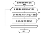
《2−4》立体物認識部4
図10は、画像処理装置10の立体物認識部4が行う処理を示すフローチャートである。立体物認識部4は、立体物抽出部1で抽出した前景画像部分200a、201a、200b及び201bから実在する立体物である実在オブジェクト40の認識を行う(ステップS40)。«2-4» Three-dimensional object recognition unit 4
FIG. 10 is a flowchart showing processing performed by the three-dimensional object recognition unit 4 of the
次に、立体物認識部4は、立体物抽出部1で抽出した前景画像部分200a及び200bの姿勢情報、すなわち、実在オブジェクトの姿勢情報を取得して、実在オブジェクトID、実在オブジェクト種別、姿勢情報を記憶部16に記憶する(ステップS41)。姿勢情報は、前景画像部分200a及び200bである2次元座標のピクセルデータから3次元座標のピクセルデータに変換するためのデータテーブルである。立体物認識部4は、姿勢情報を、前景画像部分における画像解析により予め求めてもよいし、撮像装置以外のセンサーを用いて予め取得してもよい。姿勢情報の取得方法は、特定の方法に限定されない。特に実在オブジェクト40が人物の場合、撮影画像から人物の骨格情報を取得できるため、立体物認識部4は、人物の骨格情報を姿勢情報として記憶部16に記憶させてもよい。
Next, the three-dimensional object recognition unit 4 acquires posture information of the foreground image portions 200a and 200b extracted by the three-dimensional object extraction unit 1, that is, posture information of the real object, and the real object ID, real object type, and posture information Are stored in the storage unit 16 (step S41). The posture information is a data table for converting pixel data of two-dimensional coordinates, which are the foreground image portions 200a and 200b, into pixel data of three-dimensional coordinates. The three-dimensional object recognition unit 4 may obtain posture information in advance by image analysis on a foreground image portion, or may previously obtain posture information using a sensor other than the imaging device. The acquisition method of posture information is not limited to a specific method. In particular, when the
《2−5》立体物射影投影部5
図11は、画像処理装置10の立体物射影投影部5が行う処理を示すフローチャートである。立体物射影投影部5は、立体物認識部4で取得した実在オブジェクトの姿勢情報から3次元仮想オブジェクトを生成する(ステップS50)。<< 2-5 >> Solid
FIG. 11 is a flowchart showing processing performed by the solid object projection and
次に、立体物射影投影部5は、立体物抽出部1で抽出した2次元の前景画像部分を、姿勢情報を用いて3次元仮想オブジェクトに射影投影する(ステップS51)。同じ実在オブジェクトIDである前景画像部分は、同じ3次元仮想オブジェクトに射影投影される。
Next, the three-dimensional object projection and
図12は、立体物射影投影部5が行う処理を示す説明図である。立体物射影投影部5は、認識した実在オブジェクト40に対応する3次元仮想オブジェクト400aを取得(生成を含む)する。3次元仮想オブジェクト400aは、対応する実在オブジェクト40に応じて事前に記憶部16に記憶されている複数の3次元仮想オブジェクトの候補の中から選択される。また、立体物射影投影部5は、3次元仮想オブジェクト400aを、姿勢情報を用いて作成してもよい。次に、立体物射影投影部5は、立体物抽出部1で抽出した前景画像部分200a及び200bを3次元仮想オブジェクト400aに対して射影投影する。このとき、立体物射影投影部5は、前景画像部分200a及び200bの姿勢情報を用いて3次元仮想オブジェクトに射影投影を行い、射影投影された3次元仮想オブジェクト400を生成する。
FIG. 12 is an explanatory view showing a process performed by the solid object projection and
《2−6》3次元空間重畳部6
図13は、画像処理装置10の3次元空間重畳部6が行う処理を示すフローチャートである。図14は、立体物射影投影部5が行う処理を示す説明図である。3次元空間重畳部6は、XYZ直交座標系で示される3次元空間上に、例えば、高さ0(Z=0)の平面(例えば、XY面)に背景画像合成部3で生成した背景俯瞰合成画像302を配置する(ステップS60)。<< 2-6 >> Three-dimensional space superimposing unit 6
FIG. 13 is a flowchart showing processing performed by the three-dimensional space superimposing unit 6 of the
次に、3次元空間重畳部6は、立体物射影投影部5で生成した射影投影された3次元仮想オブジェクト400を、背景俯瞰合成画像302に重ねて配置する(ステップS61)。3次元仮想オブジェクト400の配置位置は、前景画像撮影情報に含まれる位置情報を、撮像装置20a及び20bにおける内部パラメータと外部パラメータを用いて座標変換した座標である。
Next, the three-dimensional space superimposing unit 6 arranges the projection-projected three-dimensional
《2−7》表示画像出力部7
図15は、画像処理装置10の表示画像出力部7が行う処理を示すフローチャートである。表示画像出力部7は、3次元空間重畳部6で生成された3次元空間に配置された背景俯瞰合成画像302と3次元仮想オブジェクト400とからなる俯瞰合成画像、すなわち、指定された視点位置(例えば、3次元仮想オブジェクト400の真上の視点位置)から見た俯瞰合成画像を取得する(ステップS70)。<< 2-7 >> Display
FIG. 15 is a flowchart showing processing performed by the display
次に、表示画像出力部7は、取得した俯瞰合成画像を表示機器30に対して出力する(ステップS71)。
Next, the display
《3》効果
以上に説明したように、本実施の形態に係る画像処理装置10及び画像処理方法によれば、3次元空間上に平面の背景俯瞰合成画像302と3次元仮想オブジェクト400とを配置するようにしているので、複数の撮像画像100a及び100bを合成する場合、撮像画像100a及び100bが重なる範囲において立体物が2重に表示されることはなく、また、立体物が消失することもない。<< 3 >> Effects As described above, according to the
また、本実施の形態に係る画像処理装置10及び画像処理方法によれば、複数の実在オブジェクト40が存在する場合に、実在オブジェクトごとの3次元仮想オブジェクトを用いて個別に歪みを抑制することができるので、違和感のない真上から見た俯瞰画像を生成することができる。
Furthermore, according to the
さらに、本実施の形態に係る画像処理装置10及び画像処理方法によれば、真上から見た俯瞰画像だけでなく、任意の視点位置から見た俯瞰合成画像を作成することができる。したがって、画像処理装置10を監視用途で用いる場合、監視者の監視作業の効率化を図ることができる。
Furthermore, according to the
《4》利用形態の説明
本実施の形態に係る画像処理装置10及び画像処理方法は、工場の作業者の監視用の作業監視システムに適用できる。<< 4 >> Description of Usage Mode The
また、本実施の形態に係る画像処理装置10及び画像処理方法は、車両に搭載することによって、車両周辺の障害物を検出し、表示する運転支援システムに適用できる。
In addition, the
また、本実施の形態に係る画像処理装置10及び画像処理方法は、工場の生産ライン上にある作業対象物を管理する製造管理システム又は完成品の在庫状況を監視する在庫管理システムなどに適用できる。
In addition, the
1 立体物抽出部(画像分割部)、 2 背景補完部、 3 背景画像合成部、 4 立体物認識部、 5 立体物射影投影部、 6 3次元空間重畳部、 7 表示画像出力部、 10 画像処理装置、 11 プロセッサ、 12 メモリ、 13 記憶装置、 14 画像入力インタフェース、 15 表示機器インタフェース、 16 記憶部、 20a,20b 撮像画像、 30 表示機器、 40 実在オブジェクト(立体物)、 100a,100b 撮像画像、 200a,201a,200b,201b 前景画像部分、 300a,300b 背景画像部分、 302 背景俯瞰合成画像、 350 参照画像、 350a 参照画像部分、 400 射影投影された3次元仮想オブジェクト、 400a 3次元仮想オブジェクト、 500a,501a,500b,501b 前景画像撮影情報。 1 solid object extraction unit (image division unit), 2 background complementation unit, 3 background image synthesis unit, 4 solid object recognition unit, 5 solid object projection and projection unit, 6 three-dimensional space superposition unit, 7 display image output unit, 10 images Processing device, 11 processor, 12 memory, 13 storage device, 14 image input interface, 15 display device interface, 16 storage unit, 20a, 20b captured image, 30 display device, 40 real object (three-dimensional object), 100a, 100b captured image , 200a, 201a, 200b, 201b foreground image portion, 300a, 300b background image portion, 302 background view composite image, 350 reference image, 350a reference image portion, 400 projection-projected three-dimensional virtual object, 400a three-dimensional virtual object, 500a, 501 a, 500b, 501b Foreground image shooting information.
Claims (9)
予め取得されている参照画像の一部である参照画像部分を前記第1の前景画像部分の領域に貼り付けることによって前記第1の背景画像部分を補完して、補完された第1の背景画像部分を生成し、前記参照画像部分を前記第2の前景画像部分の領域に貼り付けることによって前記第2の背景画像部分を補完して、補完された第2の背景画像部分を生成する背景補完部と、
前記補完された第1の背景画像部分の視点位置と前記補完された第2の背景画像部分の視点位置とを変更する俯瞰変換を行い、俯瞰変換された前記第1の背景画像部分と俯瞰変換された前記第2の背景画像部分とを合成することによって背景俯瞰合成画像を生成する背景画像合成部と、
前記実在オブジェクトを認識し、前記実在オブジェクトの姿勢情報を取得する立体物認識部と、
前記姿勢情報を用いて、前記実在オブジェクトに対応する3次元仮想オブジェクトを取得し、前記3次元仮想オブジェクトに前記第1の前景画像部分又は前記第2の前景画像部分である前景画像部分を射影投影し、前記前景画像部分が射影投影されている前記3次元仮想オブジェクトを生成する立体物射影投影部と、
前記背景俯瞰合成画像に前記前景画像部分が射影投影されている前記3次元仮想オブジェクトを重畳して3次元空間画像を生成する3次元空間重畳部と、
前記3次元空間画像を上から見た画像である俯瞰合成画像を生成して出力する表示画像出力部と、
を有することを特徴とする画像処理装置。 Capturing a first captured image provided the target area from the first image pickup apparatus for capturing, the shooting real object is a solid object which actually exist in the shadow target area is first occupied by the foreground image portion and the first The three-dimensional object which is divided into a first background image portion other than a foreground image portion and a second captured image provided from a second imaging device for capturing the shooting target region is present in the shooting target region An image dividing unit for dividing into a second foreground image portion occupied by the existing object and a second background image portion other than the second foreground image portion ;
Complements the first background image portion by attaching the reference image portion which is a part of a reference image previously acquired in the area of the first foreground image portion, complement is first background was Background that complements the second background image portion by generating an image portion and pasting the reference image portion to the area of the second foreground image portion to generate a complemented second background image portion The complement section,
The complement to the first and the viewpoint position of the background image part performs overview transformation for changing the viewpoint position of the complemented second background image portion was, overhead and overhead converted first background image portion A background image combining unit that generates a background / overlapping composite image by combining the second background image portion that has been converted ;
A three-dimensional object recognition unit that recognizes the real object and obtains posture information of the real object;
The three-dimensional virtual object corresponding to the real object is acquired using the posture information, and the three-dimensional virtual object is projected and projected on a foreground image portion which is the first foreground image portion or the second foreground image portion. A solid object projection projection unit generating the three-dimensional virtual object on which the foreground image portion is projection-projected;
A three-dimensional space superimposing unit that generates a three-dimensional space image by superimposing the three-dimensional virtual object on which the foreground image portion is projectively projected on the background / eyelid synthetic image;
A display image output unit that generates and outputs a bird's-eye synthetic image that is an image of the three-dimensional space image viewed from above;
An image processing apparatus comprising:
前記補完された第1の背景画像部分と前記補完された第2の背景画像部分から生成された前記背景俯瞰合成画像を仮想的な3次元空間に配置し、
前記前景画像部分が射影投影されている前記3次元仮想オブジェクトを、前記背景俯瞰合成画像が配置されている前記仮想的な3次元空間に配置する
ことを特徴とする請求項1に記載の画像処理装置。 The three-dimensional space superimposing unit is
Placing the complement is the first of the background bird's-eye synthesized image generated from the second background image portion the complemented background image part was in a virtual three-dimensional space,
The image processing according to claim 1, wherein the three-dimensional virtual object on which the foreground image portion is projectively projected is arranged in the virtual three-dimensional space in which the background / overlapping composite image is arranged. apparatus.
予め取得されている参照画像の一部である参照画像部分を前記第1の前景画像部分の領域に貼り付けることによって前記第1の背景画像部分を補完して、補完された第1の背景画像部分を生成し、前記参照画像部分を前記第2の前景画像部分の領域に貼り付けることによって前記第2の背景画像部分を補完して、補完された第2の背景画像部分を生成するステップと、
前記補完された第1の背景画像部分の視点位置と前記補完された第2の背景画像部分の視点位置とを変更する俯瞰変換を行い、俯瞰変換された前記第1の背景画像部分と俯瞰変換された前記第2の背景画像部分とを合成することによって背景俯瞰合成画像を生成するステップと、
前記実在オブジェクトを認識し、前記実在オブジェクトの姿勢情報を取得するステップと、
前記姿勢情報を用いて、前記実在オブジェクトに対応する3次元仮想オブジェクトを取得し、前記3次元仮想オブジェクトに前記第1の前景画像部分又は前記第2の前景画像部分である前景画像部分を射影投影し、前記前景画像部分が射影投影されている前記3次元仮想オブジェクトを生成するステップと、
前記背景俯瞰合成画像に前記前景画像部分が射影投影されている前記3次元仮想オブジェクトを重畳して3次元空間画像を生成するステップと、
前記3次元空間画像を上から見た画像である俯瞰合成画像を生成して出力するステップと、
を有することを特徴とする画像処理方法。 Capturing a first captured image provided the target area from the first image pickup apparatus for capturing, the shooting real object is a solid object which actually exist in the shadow target area is first occupied by the foreground image portion and the first The three-dimensional object which is divided into a first background image portion other than a foreground image portion and a second captured image provided from a second imaging device for capturing the shooting target region is present in the shooting target region Dividing into a second foreground image portion occupied by the existing object and a second background image portion other than the second foreground image portion ;
Complements the first background image portion by attaching the reference image portion which is a part of a reference image previously acquired in the area of the first foreground image portion, complement is first background was Generating the image portion and complementing the second background image portion by pasting the reference image portion to the area of the second foreground image portion to generate a complemented second background image portion When,
The complement to the first and the viewpoint position of the background image part performs overview transformation for changing the viewpoint position of the complemented second background image portion was, overhead and overhead converted first background image portion Generating a background / 俯瞰 composite image by combining with the converted second background image portion ;
Recognizing the real object and acquiring posture information of the real object;
The three-dimensional virtual object corresponding to the real object is acquired using the posture information, and the three-dimensional virtual object is projected and projected on a foreground image portion which is the first foreground image portion or the second foreground image portion. Generating the three-dimensional virtual object on which the foreground image portion is projectively projected;
Superimposing the three-dimensional virtual object on which the foreground image portion is project-projected on the background / 俯瞰 composite image to generate a three-dimensional space image;
Generating and outputting a bird's-eye view composite image which is an image of the three-dimensional space image viewed from above;
An image processing method comprising:
予め取得されている参照画像の一部である参照画像部分を前記第1の前景画像部分の領域に貼り付けることによって前記第1の背景画像部分を補完して、補完された第1の背景画像部分を生成し、前記参照画像部分を前記第2の前景画像部分の領域に貼り付けることによって前記第2の背景画像部分を補完して、補完された第2の背景画像部分を生成する処理と、
前記補完された第1の背景画像部分の視点位置と前記補完された第2の背景画像部分の視点位置とを変更する俯瞰変換を行い、俯瞰変換された前記第1の背景画像部分と俯瞰変換された前記第2の背景画像部分とを合成することによって背景俯瞰合成画像を生成する処理と、
前記実在オブジェクトを認識し、前記実在オブジェクトの姿勢情報を取得する処理と、
前記姿勢情報を用いて、前記実在オブジェクトに対応する3次元仮想オブジェクトを取得し、前記3次元仮想オブジェクトに前記第1の前景画像部分又は前記第2の前景画像部分である前景画像部分を射影投影し、前記前景画像部分が射影投影されている前記3次元仮想オブジェクトを生成する処理と、
前記背景俯瞰合成画像に前記前景画像部分が射影投影されている前記3次元仮想オブジェクトを重畳して3次元空間画像を生成する処理と、
前記3次元空間画像を上から見た画像である俯瞰合成画像を生成して出力する処理と、
をコンピュータに実行させることを特徴とする画像処理プログラム。 Capturing a first captured image provided the target area from the first image pickup apparatus for capturing, the shooting real object is a solid object which actually exist in the shadow target area is first occupied by the foreground image portion and the first The three-dimensional object which is divided into a first background image portion other than a foreground image portion and a second captured image provided from a second imaging device for capturing the shooting target region is present in the shooting target region A process of dividing into a second foreground image portion occupied by a real object, and a second background image portion other than the second foreground image portion ;
Complements the first background image portion by attaching the reference image portion which is a part of a reference image previously acquired in the area of the first foreground image portion, complement is first background was Processing for complementing the second background image portion by generating an image portion and pasting the reference image portion to the area of the second foreground image portion to generate a complemented second background image portion When,
The complement to the first and the viewpoint position of the background image part performs overview transformation for changing the viewpoint position of the complemented second background image portion was, overhead and overhead converted first background image portion A process of generating a background / 俯瞰 composite image by combining the second background image portion that has been converted ;
A process of recognizing the real object and acquiring posture information of the real object;
The three-dimensional virtual object corresponding to the real object is acquired using the posture information, and the three-dimensional virtual object is projected and projected on a foreground image portion which is the first foreground image portion or the second foreground image portion. Generating the three-dimensional virtual object on which the foreground image portion is projected and projected;
A process of generating a three-dimensional space image by superimposing the three-dimensional virtual object on which the foreground image portion is projectively projected on the background / 俯瞰 synthetic image;
A process of generating and outputting a bird's-eye synthetic image which is an image of the three-dimensional space image viewed from above;
An image processing program for causing a computer to execute the program.
Applications Claiming Priority (1)
| Application Number | Priority Date | Filing Date | Title |
|---|---|---|---|
| PCT/JP2018/012852 WO2019186787A1 (en) | 2018-03-28 | 2018-03-28 | Image processing device, image processing method, and image processing program |
Publications (2)
| Publication Number | Publication Date |
|---|---|
| JP6513300B1 true JP6513300B1 (en) | 2019-05-15 |
| JPWO2019186787A1 JPWO2019186787A1 (en) | 2020-04-30 |
Family
ID=66530751
Family Applications (1)
| Application Number | Title | Priority Date | Filing Date |
|---|---|---|---|
| JP2018540890A Active JP6513300B1 (en) | 2018-03-28 | 2018-03-28 | IMAGE PROCESSING APPARATUS, IMAGE PROCESSING METHOD, AND IMAGE PROCESSING PROGRAM |
Country Status (5)
| Country | Link |
|---|---|
| US (1) | US11403742B2 (en) |
| JP (1) | JP6513300B1 (en) |
| CN (1) | CN111886624A (en) |
| GB (1) | GB2586712B (en) |
| WO (1) | WO2019186787A1 (en) |
Cited By (1)
| Publication number | Priority date | Publication date | Assignee | Title |
|---|---|---|---|---|
| WO2021040075A1 (en) * | 2019-08-27 | 2021-03-04 | 엘지전자 주식회사 | Image display apparatus and image processing method thereof |
Families Citing this family (8)
| Publication number | Priority date | Publication date | Assignee | Title |
|---|---|---|---|---|
| US11429814B2 (en) * | 2018-04-12 | 2022-08-30 | Nec Corporation | Learning image generation apparatus, learning image generation method, and non-transitory storage medium |
| EP3968274B1 (en) * | 2020-09-14 | 2025-03-12 | Tata Consultancy Services Limited | Method and system for asset inspection using unmanned aerial vehicles |
| WO2022181174A1 (en) * | 2021-02-24 | 2022-09-01 | ソニーグループ株式会社 | Image processing device, image processing method, and projector device |
| CN115914497B (en) * | 2021-08-24 | 2026-03-13 | 北京字跳网络技术有限公司 | Video processing methods, apparatus, equipment, media and program products |
| CN113538318B (en) * | 2021-08-24 | 2023-12-15 | 北京奇艺世纪科技有限公司 | Image processing method, device, terminal equipment and readable storage medium |
| CN114612564B (en) * | 2022-03-28 | 2026-03-31 | 欧姆龙(上海)有限公司 | Image data generation methods, apparatuses, and electronic devices |
| US12536617B2 (en) * | 2022-08-12 | 2026-01-27 | Purdue Research Foundation | Fused images backgrounds |
| WO2024142361A1 (en) * | 2022-12-28 | 2024-07-04 | 三菱電機株式会社 | Video synthesizing device, video synthesizing method, and video synthesizing program |
Citations (4)
| Publication number | Priority date | Publication date | Assignee | Title |
|---|---|---|---|---|
| JP2000184336A (en) * | 1998-10-09 | 2000-06-30 | Canon Inc | Image processing apparatus, image processing method, and computer-readable storage medium |
| JP2010128742A (en) * | 2008-11-27 | 2010-06-10 | Casio Computer Co Ltd | Three-dimensional data creation device |
| WO2012046392A1 (en) * | 2010-10-08 | 2012-04-12 | パナソニック株式会社 | Posture estimation device and posture estimation method |
| JP2012147149A (en) * | 2011-01-11 | 2012-08-02 | Aisin Seiki Co Ltd | Image generating apparatus |
Family Cites Families (16)
| Publication number | Priority date | Publication date | Assignee | Title |
|---|---|---|---|---|
| US20050031169A1 (en) * | 2003-08-09 | 2005-02-10 | Alan Shulman | Birds eye view virtual imaging for real time composited wide field of view |
| JP4934308B2 (en) * | 2005-10-17 | 2012-05-16 | 三洋電機株式会社 | Driving support system |
| US7728879B2 (en) * | 2006-08-21 | 2010-06-01 | Sanyo Electric Co., Ltd. | Image processor and visual field support device |
| CN101765527A (en) * | 2007-07-31 | 2010-06-30 | 株式会社丰田自动织机 | Parking assistance device, vehicle-side device for parking assistance device, parking assistance method, and parking assistance program |
| JP5053043B2 (en) | 2007-11-09 | 2012-10-17 | アルパイン株式会社 | Vehicle peripheral image generation device and vehicle peripheral image distortion correction method |
| JP4697480B2 (en) * | 2008-01-11 | 2011-06-08 | 日本電気株式会社 | Lane recognition device, lane recognition method, and lane recognition program |
| JP5067632B2 (en) * | 2008-11-28 | 2012-11-07 | アイシン精機株式会社 | Bird's-eye image generator |
| WO2012007993A1 (en) * | 2010-07-14 | 2012-01-19 | 三菱電機株式会社 | Image synthesis device |
| TWI433529B (en) * | 2010-09-21 | 2014-04-01 | Huper Lab Co Ltd | Method for intensifying 3d objects identification |
| KR101751405B1 (en) * | 2010-10-22 | 2017-06-27 | 히다치 겡키 가부시키 가이샤 | Work machine peripheral monitoring device |
| JP5962927B2 (en) * | 2011-09-30 | 2016-08-03 | パナソニックIpマネジメント株式会社 | Overhead image generation apparatus, overhead image generation method, and overhead image generation program |
| US8970701B2 (en) * | 2011-10-21 | 2015-03-03 | Mesa Engineering, Inc. | System and method for predicting vehicle location |
| US20160379074A1 (en) * | 2015-06-25 | 2016-12-29 | Appropolis Inc. | System and a method for tracking mobile objects using cameras and tag devices |
| US10417743B2 (en) | 2015-11-06 | 2019-09-17 | Mitsubishi Electric Corporation | Image processing device, image processing method and computer readable medium |
| US10678257B2 (en) * | 2017-09-28 | 2020-06-09 | Nec Corporation | Generating occlusion-aware bird eye view representations of complex road scenes |
| TWI657409B (en) * | 2017-12-27 | 2019-04-21 | 財團法人工業技術研究院 | Superimposition device of virtual guiding indication and reality image and the superimposition method thereof |
-
2018
- 2018-03-28 JP JP2018540890A patent/JP6513300B1/en active Active
- 2018-03-28 CN CN201880091553.9A patent/CN111886624A/en active Pending
- 2018-03-28 GB GB2014492.9A patent/GB2586712B/en active Active
- 2018-03-28 WO PCT/JP2018/012852 patent/WO2019186787A1/en not_active Ceased
-
2020
- 2020-09-22 US US17/028,508 patent/US11403742B2/en active Active
Patent Citations (4)
| Publication number | Priority date | Publication date | Assignee | Title |
|---|---|---|---|---|
| JP2000184336A (en) * | 1998-10-09 | 2000-06-30 | Canon Inc | Image processing apparatus, image processing method, and computer-readable storage medium |
| JP2010128742A (en) * | 2008-11-27 | 2010-06-10 | Casio Computer Co Ltd | Three-dimensional data creation device |
| WO2012046392A1 (en) * | 2010-10-08 | 2012-04-12 | パナソニック株式会社 | Posture estimation device and posture estimation method |
| JP2012147149A (en) * | 2011-01-11 | 2012-08-02 | Aisin Seiki Co Ltd | Image generating apparatus |
Cited By (1)
| Publication number | Priority date | Publication date | Assignee | Title |
|---|---|---|---|---|
| WO2021040075A1 (en) * | 2019-08-27 | 2021-03-04 | 엘지전자 주식회사 | Image display apparatus and image processing method thereof |
Also Published As
| Publication number | Publication date |
|---|---|
| GB2586712B (en) | 2021-12-22 |
| GB202014492D0 (en) | 2020-10-28 |
| WO2019186787A1 (en) | 2019-10-03 |
| JPWO2019186787A1 (en) | 2020-04-30 |
| US20210004943A1 (en) | 2021-01-07 |
| US11403742B2 (en) | 2022-08-02 |
| CN111886624A (en) | 2020-11-03 |
| GB2586712A (en) | 2021-03-03 |
Similar Documents
| Publication | Publication Date | Title |
|---|---|---|
| JP6513300B1 (en) | IMAGE PROCESSING APPARATUS, IMAGE PROCESSING METHOD, AND IMAGE PROCESSING PROGRAM | |
| JP6425780B1 (en) | Image processing system, image processing apparatus, image processing method and program | |
| JP7002056B2 (en) | 3D model generator and 3D model generation method | |
| JP6021541B2 (en) | Image processing apparatus and method | |
| US10699473B2 (en) | System and method for generating a virtual viewpoint apparatus | |
| CN106254854B (en) | Preparation method, the apparatus and system of 3-D image | |
| US10349040B2 (en) | Storing data retrieved from different sensors for generating a 3-D image | |
| JP5845123B2 (en) | Three-dimensional model-integral image conversion apparatus and program thereof | |
| CN113132708B (en) | Method and apparatus for acquiring three-dimensional scene image using fisheye camera, device and medium | |
| KR102067823B1 (en) | Method and apparatus for operating 2d/3d augument reality technology | |
| CN113348489A (en) | Image processing method and device | |
| JP6021489B2 (en) | Imaging apparatus, image processing apparatus and method thereof | |
| WO2018052100A1 (en) | Image processing device, image processing method, and image processing program | |
| KR101801100B1 (en) | Video providing apparatus and method for supporting production of immersive contents | |
| US12148211B2 (en) | Image processing apparatus and 3D model generation method | |
| KR20220121533A (en) | Image restoration method and image restoration apparatus for restoring images acquired through an array camera | |
| TWI615808B (en) | Image processing method for immediately producing panoramic images | |
| JP2008217593A (en) | Subject area extraction device and subject area extraction program | |
| US20200311884A1 (en) | Method and apparatus for generating virtual reality image inside vehicle using image stitching technique | |
| KR102019879B1 (en) | Apparatus and method for acquiring 360 VR images in a game using a virtual camera | |
| JP2014164497A (en) | Information processor, image processing method and program | |
| KR101718309B1 (en) | The method of auto stitching and panoramic image genertation using color histogram | |
| JP2008017386A (en) | Key image generation device | |
| JP2014049895A (en) | Image processing method | |
| JP2012150614A (en) | Free viewpoint image generation device |
Legal Events
| Date | Code | Title | Description |
|---|---|---|---|
| A521 | Request for written amendment filed |
Free format text: JAPANESE INTERMEDIATE CODE: A523 Effective date: 20180803 |
|
| A621 | Written request for application examination |
Free format text: JAPANESE INTERMEDIATE CODE: A621 Effective date: 20180803 |
|
| A871 | Explanation of circumstances concerning accelerated examination |
Free format text: JAPANESE INTERMEDIATE CODE: A871 Effective date: 20180803 |
|
| A975 | Report on accelerated examination |
Free format text: JAPANESE INTERMEDIATE CODE: A971005 Effective date: 20180828 |
|
| A131 | Notification of reasons for refusal |
Free format text: JAPANESE INTERMEDIATE CODE: A131 Effective date: 20181113 |
|
| A521 | Request for written amendment filed |
Free format text: JAPANESE INTERMEDIATE CODE: A523 Effective date: 20181214 |
|
| TRDD | Decision of grant or rejection written | ||
| A01 | Written decision to grant a patent or to grant a registration (utility model) |
Free format text: JAPANESE INTERMEDIATE CODE: A01 Effective date: 20190312 |
|
| A61 | First payment of annual fees (during grant procedure) |
Free format text: JAPANESE INTERMEDIATE CODE: A61 Effective date: 20190409 |
|
| R150 | Certificate of patent or registration of utility model |
Ref document number: 6513300 Country of ref document: JP Free format text: JAPANESE INTERMEDIATE CODE: R150 |
|
| R250 | Receipt of annual fees |
Free format text: JAPANESE INTERMEDIATE CODE: R250 |
|
| R250 | Receipt of annual fees |
Free format text: JAPANESE INTERMEDIATE CODE: R250 |
|
| R250 | Receipt of annual fees |
Free format text: JAPANESE INTERMEDIATE CODE: R250 |
|
| R250 | Receipt of annual fees |
Free format text: JAPANESE INTERMEDIATE CODE: R250 |