JP6510990B2 - Wavelength variable light source and driving method thereof - Google Patents
Wavelength variable light source and driving method thereof Download PDFInfo
- Publication number
- JP6510990B2 JP6510990B2 JP2016015539A JP2016015539A JP6510990B2 JP 6510990 B2 JP6510990 B2 JP 6510990B2 JP 2016015539 A JP2016015539 A JP 2016015539A JP 2016015539 A JP2016015539 A JP 2016015539A JP 6510990 B2 JP6510990 B2 JP 6510990B2
- Authority
- JP
- Japan
- Prior art keywords
- actuator
- angle
- light source
- frequency
- wavelength
- Prior art date
- Legal status (The legal status is an assumption and is not a legal conclusion. Google has not performed a legal analysis and makes no representation as to the accuracy of the status listed.)
- Expired - Fee Related
Links
Images


Landscapes
- Mechanical Light Control Or Optical Switches (AREA)
- Semiconductor Lasers (AREA)
Description
本発明は、波長可変光源及びその駆動方法に関する。 The present invention relates to a wavelength tunable light source and a method of driving the same.
吸光分析等に用いられる光源として、回折格子を回転させることにより、波長の選択を行う外部共振器型の波長可変光源が知られている。回折格子の回転には、ステップ動作型アクチュエータ(例えば、特許文献1参照)、または、MEMS(Micro Electro Mechanical Systems)アクチュエータ(例えば、特許文献2参照)が用いられている。ステップ動作型アクチュエータは、可動範囲が広く、任意の角度で精度よく静止することができる。一方、MEMSアクチュエータは、スキャンレートが高く、吸光分析等に用いた場合、積算及び平均化により短時間でS/Nを向上させることができる。 As a light source used for light absorption analysis or the like, an external resonator-type wavelength-tunable light source of which wavelength is selected by rotating a diffraction grating is known. For rotation of the diffraction grating, a step operation type actuator (for example, refer to Patent Document 1) or a MEMS (Micro Electro Mechanical Systems) actuator (for example, refer to Patent Document 2) is used. The step-motion actuator has a wide movable range, and can accurately stop at an arbitrary angle. On the other hand, the MEMS actuator has a high scan rate, and when it is used for absorption analysis etc., S / N can be improved in a short time by integration and averaging.
ステップ動作型アクチュエータは、スキャンレートが低いため、吸光分析等に用いた場合、MEMSアクチュエータのように短時間でS/Nを向上させることができない。一方、MEMSアクチュエータは、可動範囲が狭く、任意の角度で精度よく回折格子を静止させることができないため、ステップ動作型アクチュエータのように広い波長範囲及び高い波長制御性を実現することができない。 Since the step rate actuator has a low scan rate, it can not improve S / N in a short time as in the case of a MEMS actuator when it is used for absorption analysis or the like. On the other hand, since the MEMS actuator has a narrow movable range and can not accurately stop the diffraction grating at an arbitrary angle, it can not realize a wide wavelength range and high wavelength controllability like a step operation type actuator.
本発明は、広い波長範囲及び高い波長制御性を維持しながら、スキャンレートを高めることができる波長可変光源及びその駆動方法を提供することを目的とする。 An object of the present invention is to provide a wavelength tunable light source capable of enhancing a scan rate while maintaining a wide wavelength range and high wavelength controllability, and a method of driving the same.
本発明に係る波長可変光源は、パルス光を出射する半導体レーザと、半導体レーザと共に外部共振器を構成する回折格子であって、半導体レーザから出射されたパルス光が入射し、パルス光のうち入射角に応じた波長の光を半導体レーザに帰還させる回折格子と、回折格子を回転駆動して入射角を変化させる回転駆動部と、を備え、回転駆動部は、回転シャフトを含み、ステップ動作型である第一アクチュエータと、支持部と、回折格子が設けられた可動部と、可動部を支持部に回転可能に連結する連結部と、を含む第二アクチュエータと、を有し、第二アクチュエータは、可動部の回転軸が回転シャフトの中心軸と一致するように回転シャフトに取り付けられている。 The variable-wavelength light source according to the present invention is a semiconductor laser that emits pulsed light and a diffraction grating that constitutes an external resonator together with the semiconductor laser, and the pulsed light emitted from the semiconductor laser is incident and is incident among the pulsed light. A diffraction grating for returning light of a wavelength according to an angle to a semiconductor laser, and a rotation drive unit for rotating the diffraction grating to change an incident angle, the rotation drive unit including a rotation shaft, and a step operation type A second actuator including a first actuator, a support, a movable part provided with a diffraction grating, and a connecting part rotatably connecting the movable part to the support; Is mounted on the rotating shaft such that the rotation axis of the movable part coincides with the central axis of the rotation shaft.
この波長可変光源では、外部共振器を構成する回折格子を回転駆動する回転駆動部が、ステップ動作型である第一アクチュエータに加え、第二アクチュエータを有している。第二アクチュエータは、連結部により支持部に回転可能に連結され、かつ、回折格子が設けられた可動部を含んでいる。このため、第一アクチュエータにより広い波長範囲及び高い波長制御性を維持しながら、第二アクチュエータによりスキャンレートを高めることができる。また、可動部の回転軸が回転シャフトの中心軸と一致しているので、外部共振器の長さが一定に保たれる。これにより、波長の再現性及び安定性が保たれる。 In this wavelength tunable light source, a rotational drive unit for rotationally driving a diffraction grating that constitutes an external resonator includes a second actuator in addition to the first actuator that is a step operation type. The second actuator is rotatably connected to the support by a connection and includes a movable portion provided with a diffraction grating. Therefore, the scan rate can be increased by the second actuator while maintaining a wide wavelength range and high wavelength controllability by the first actuator. In addition, since the rotation axis of the movable part coincides with the central axis of the rotation shaft, the length of the external resonator is kept constant. This maintains the repeatability and stability of the wavelength.
本発明に係る波長可変光源の駆動方法は、上述の波長可変光源の駆動方法であって、第一アクチュエータを駆動するステップと、第一アクチュエータを停止させた状態で、第二アクチュエータを駆動するステップと、を含む。 A method of driving a variable-wavelength light source according to the present invention is the method of driving a variable-wavelength light source described above, comprising the steps of: driving a first actuator; and driving a second actuator with the first actuator stopped. And.
この波長可変光源の駆動方法では、たとえば、吸光分析に適用した際、第一アクチュエータにより広い波長範囲で粗動スキャンを行った後、より詳細に分析すべき波長範囲を絞り込み、絞り込んだ範囲を第二アクチュエータにより高速で微動スキャンすることができる。これにより、分析可能な波長範囲を広く維持しながら、任意の波長範囲における分析の精度を高めることができる。 In this method of driving a variable wavelength light source, for example, when applied to absorption analysis, after performing coarse movement scan in a wide wavelength range by the first actuator, the wavelength range to be analyzed in more detail is narrowed down and the narrowed range is narrowed Fine movement scanning can be performed at high speed by the two actuators. This makes it possible to increase the accuracy of analysis in any wavelength range while maintaining a wide range of wavelength that can be analyzed.
本発明に係る波長可変光源の駆動方法は、上述の波長可変光源の駆動方法であって、第一アクチュエータとして、ステッピングモータを用い、入射角が1ステップで第一角度ずつ変化するように第一アクチュエータを第一周波数で駆動すると共に、入射角が第二角度を最大振幅として増減するように第二アクチュエータを第二周波数で駆動し、第一周波数と第二周波数とは互いに等しく、第一角度をΔθとすると、第二角度はΔθ/8である。 A method of driving a variable wavelength light source according to the present invention is the method of driving a variable wavelength light source described above, wherein a stepping motor is used as the first actuator, and the incident angle is changed by the first angle in one step. The actuator is driven at a first frequency and the second actuator is driven at a second frequency such that the incident angle increases or decreases with the second angle as the maximum amplitude, the first frequency and the second frequency being equal to each other, the first angle Where Δθ is the second angle is Δθ / 8.
この波長可変光源の駆動方法では、第一アクチュエータを用いた場合に生じる回折格子の角速度のムラを、第二アクチュエータにより打ち消すことができる。これにより、波長可変光源から出射される光の波長の変化速度を一定とすることができる。 In this driving method of the wavelength variable light source, the unevenness of the angular velocity of the diffraction grating generated when the first actuator is used can be canceled by the second actuator. Thereby, the change speed of the wavelength of the light emitted from the variable wavelength light source can be made constant.
本発明に係る波長可変光源の駆動方法は、上述の波長可変光源の駆動方法であって、第一アクチュエータとして、超音波モータを用い、入射角が1ステップで第一角度ずつ変化するように第一アクチュエータを第一周波数で駆動すると共に、入射角が第二角度を最大振幅として増減するように第二アクチュエータを第二周波数で駆動し、第一周波数をfとすると、第二周波数は2fであり、第一角度をΔθとすると、第二角度はΔθ/16である。 The method of driving a variable wavelength light source according to the present invention is the method of driving a variable wavelength light source described above, wherein an ultrasonic motor is used as the first actuator, and the incident angle is changed by each first angle in one step. Assuming that one actuator is driven at a first frequency and the second actuator is driven at a second frequency such that the incident angle increases or decreases with the second angle as the maximum amplitude, and the first frequency is f, the second frequency is 2f If the first angle is Δθ, the second angle is Δθ / 16.
この波長可変光源の駆動方法では、第一アクチュエータを用いた場合に生じる回折格子の角速度のムラを、第二アクチュエータにより打ち消すことができる。これにより、波長可変光源から出射される光の波長の変化速度を一定とすることができる。 In this driving method of the wavelength variable light source, the unevenness of the angular velocity of the diffraction grating generated when the first actuator is used can be canceled by the second actuator. Thereby, the change speed of the wavelength of the light emitted from the variable wavelength light source can be made constant.
本発明によれば、広い波長範囲及び高い波長制御性を維持しながら、スキャンレートを高めることができる。 According to the present invention, the scan rate can be increased while maintaining a wide wavelength range and high wavelength controllability.
以下、本発明の実施形態について、図面を参照して詳細に説明する。なお、各図において同一又は相当部分には同一符号を付し、重複する説明を省略する。 Hereinafter, embodiments of the present invention will be described in detail with reference to the drawings. In the drawings, the same or corresponding parts are denoted by the same reference numerals and redundant description will be omitted.
図1は、本実施形態に係る波長可変光源を用いた吸光分析装置の構成図である。図1に示されるように、吸光分析装置100は、ガスの成分を分析する装置であって、波長可変光源10と、回転制御部12と、ガスセル16と、レンズ18と、ディテクタ20と、ロックインアンプ22と、オシロスコープ24と、を備えている。
FIG. 1 is a block diagram of an absorption analyzer using a variable wavelength light source according to the present embodiment. As shown in FIG. 1, the
図2は、本実施形態に係る波長可変光源の構成図である。図1及び図2に示されるように、波長可変光源10は、半導体レーザ1と、レーザ駆動部2と、レンズ3と、回折格子4と、回転駆動部5と、レンズ7と、筐体8と、を備えている。なお、筐体8は図2では省略されている。
FIG. 2 is a block diagram of the wavelength tunable light source according to the present embodiment. As shown in FIGS. 1 and 2, the variable
半導体レーザ1は、互いに対向する第一端1a及び第二端1bを有している。本実施形態では、半導体レーザ1は、量子カスケードレーザ(QCL:Quantum Cascade Laser)である。量子カスケードレーザは、中心波長が互いに異なる複数の活性層をスタック状に積層した構造を有することで、中赤外領域の広帯域の光を出射することができる。半導体レーザ1は、レーザ駆動部2から駆動電流信号S0が入力(印加)されることによりパルス光L1を発生(点灯)させ、第一端1aからパルス光L1を出射する。なお、半導体レーザ1は、量子カスケードレーザに限られない。
The
第一端1aは反射低減膜(不図示)を含んでいる。これにより、第一端1aから外部へ光が出射する際の反射率がたとえば5%以下に低減され、また、外部から第一端1aへ光が入射する際の反射率がたとえば5%以下に低減される。第二端1bは、発振に適した端面反射率を得るための反射制御膜(不図示)を含んでいる。これにより、第二端1bから外部へ光が出射する際の反射率が50%〜90%とされる。
The
レーザ駆動部2は、半導体レーザ1を駆動する。レーザ駆動部2は、駆動電流信号S0を半導体レーザ1に出力するレーザ駆動用電源である。レーザ駆動部2は、他の装置(不図示)から入力した信号を外部トリガをとし、駆動電流信号S0を出力してもよい。駆動電流信号S0は、たとえばパルス信号であって、駆動電流信号S0のデューティー比は、たとえば1%〜10%である。
The
レンズ3は、第一端1aから出射されるパルス光L1をコリメートする。レンズ3は、発振波長において透明な材料(たとえばZnSe)からなる。レンズ3は、球面収差低減のために非球面レンズであってもよい。レンズ3は、発振波長において反射率をたとえば5%以下に低減する反射低減膜が両面に設けられていてもよい。
The
回折格子4は、たとえば、格子の断面が鋸歯形状であるブレーズド回折格子である。回折格子4には、第一端1aから出射され、レンズ3によりコリメートされたパルス光L1が入射する。回折格子4の格子面には、高反射率の反射膜4aが設けられている。これにより、回折格子4は、入射したパルス光L1のうち、入射角θに応じた波長λの光を入射方向と逆方向に回折させて、回折光L2として第一端1aに帰還させる。入射角θは、パルス光L1の光軸Aと格子面の法線とがなす角度である。
The
回折格子4の格子周期(刻み間隔)dを決定すれば、下記(1)式によって、帰還させるべき波長λに対する入射角θが一意に決まる。リトロー配置であるから、回折次数mは1とする。入射角と回折角とは等しい。
mλ=2d・sinθ …(1)
If the grating period (step interval) d of the
mλ = 2d · sin θ (1)
回折格子4と、半導体レーザ1の特に第二端1bとは、リトロー型の外部共振器(EC:ExternalCavity)Eを構成している。すなわち、半導体レーザ1は、外部共振型量子カスケードレーザ(EC−QCL)であり、広い波長可変幅を実現し、複数物質(特に有機物質)の吸光分析を行うことができる。回折格子4と第二端1bとは、回折光L2を多重反射させて増幅する。回折格子4と第二端1bとは、これにより得られたパルス状のレーザ光L3を第二端1bから出射する。
The
回転駆動部5は、ステップ動作型である第一アクチュエータ51と、MEMSアクチュエータである第二アクチュエータ52と、を有するハイブリッドアクチュエータである。回転駆動部5は、回転制御部12から制御信号S1,S2を入力し、入力した制御信号S1,S2に基づき、回折格子4を回転駆動して入射角θを変化させる。回転駆動部5による回折格子4の回転角は、パルス光L1の光軸Aと格子面の法線とがなす角度であって、入射角θに等しい。
The
第一アクチュエータ51は、回転シャフト53(図3参照)を含んでいる。回転シャフト53には、第二アクチュエータ52が取り付けられている。第一アクチュエータ51は、たとえば超音波モータ及びステッピングモータである。本実施形態では、第一アクチュエータ51はステッピングモータである。
The
図3は、格子面の法線方向から見た第二アクチュエータの構成図である。図3に示されるように、第二アクチュエータ52は、支持部55と、可動部56と、一対の連結部57と、を含んでいる。支持部55は、外側輪郭が矩形状を呈する枠体である。可動部56は、外側輪郭が矩形状を呈する平板であり、支持部55の内側に支持部55から離間して配置されている。可動部56には、回折格子4が設けられている。
FIG. 3 is a configuration diagram of the second actuator as viewed from the normal direction of the lattice plane. As shown in FIG. 3, the
一対の連結部57は、可動部56を支持部55に回転可能に連結している。本実施形態では、支持部55、可動部56、及び一対の連結部57は、一体に形成されており、たとえばSiからなっている。第二アクチュエータ52は、可動部56の回転軸R2が回転シャフト53の中心軸R1と一致するように回転シャフト53に取り付けられている。
The pair of connecting
第二アクチュエータ52は、制御信号S2に基づき、一対の連結部57の中心軸を回転軸R2として、所定の振り角(最大で±15°程度)及び所定の周波数(たとえば1kHz)で可動部56を回転させることにより、回折格子4(図2参照)を回転駆動する。すなわち、第二アクチュエータ52は、所定の振り角を最大振幅として入射角θを所定の周波数で増減させる。第二アクチュエータ52の駆動方式は、電磁方式、静電方式及び圧電方式等である。
The
図1〜図3に示されるように、第一アクチュエータ51は、移動命令信号である制御信号S1に基づき動作し、回転シャフト53に取り付けられた第二アクチュエータ52を回転駆動する。第二アクチュエータ52には回折格子4が設けられているため、第一アクチュエータ51は、回折格子4を第二アクチュエータ52ごと回転駆動する。第一アクチュエータ51は、ステップ動作型であるため、最小移動ステップ(最小回転量)が離散的となる。第一アクチュエータ51の最小移動ステップは、たとえば0.0025°である。第一アクチュエータ51の回転速度は、0.5rpm〜数rpm程度であり、スキャンレート(1秒間あたりの波長スキャン回数)は最大で10Hz程度である。
As shown in FIGS. 1 to 3, the
レンズ7は、第二端1bから出射されるレーザ光L3をコリメートする。レンズ7は、発振波長において透明な材料(たとえばZnSe)からなる。レンズ7は、球面収差低減のために非球面レンズであってもよい。レンズ7は、発振波長において反射率をたとえば5%以下に低減する反射低減膜が両面に設けられていてもよい。
The
筐体8は、半導体レーザ1と、レンズ3と、回折格子4と、回転駆動部5と、レンズ7とを内部に収容する。筐体8は、窓8aを有している。窓8aからは、第二端1bから出射されレンズ7によりコリメートされたレーザ光L3が外部へ出射される。窓8aは、発振波長において透明な材料(たとえばZnSe)からなり、発振波長において反射率をたとえば5%以下に低減する反射低減膜が両面に設けられていてもよい。
The
回転制御部12は、制御信号S1,S2を回転駆動部5に出力して、回転駆動部5の回転を制御する。具体的には、回転制御部12は、制御信号S1を第一アクチュエータ51に出力し、制御信号S2を第二アクチュエータ52に出力する。
The
ガスセル16は、筒状の容器であり、気体の流入口16a及び流出口16bを有している。ガスセル16は、ガス分析の対象となる気体がガスセル16の軸方向に沿って内部を流れるように構成されている。ガスセル16は、レーザ光L3をガスセル16内に入射させる第一窓16cを軸方向の一端に有し、気体を通過したレーザ光L4をガスセル16外に出射させる第二窓16dを軸方向の他端に有している。
The
レンズ18は、レーザ光L4を集光し、集光された光をディテクタ20に受光させる。ディテクタ20は、レンズ18により集光された光を受光し、受光した光の強度を電気信号S3に変換する。ディテクタ20は、たとえばフォトダイオードである。ディテクタ20は、電気信号S3をロックインアンプに出力する。
The
ロックインアンプ22は、ディテクタ20から電気信号S3を入力すると共に、レーザ駆動部2から駆動電流信号S0を参照信号として入力する。ロックインアンプ22は、駆動電流信号S0に基づいて、電気信号S3から不要なノイズを取り除き、光出力(強度)を示す信号として電気信号S4をオシロスコープ24に出力する。
The lock-in
オシロスコープ24は、ロックインアンプ22から電気信号S4を入力し、電気信号S4に基づき、たとえばガス吸収線を分析結果として出力する。ガス吸収線は、横軸を時間(波長)、縦軸を光出力としたグラフである。
The
続いて、吸光分析装置100の駆動方法、具体的には波長可変光源10の駆動方法について説明する。まず、制御信号S1,S2を回転制御部12から出力し、回転駆動部5に入力する。これにより回転駆動部5を駆動する。この結果、回折格子4が回転駆動部5により回転駆動されて入射角θが変化する。
Subsequently, a method of driving the
このとき、まず、第二アクチュエータ52を停止させた状態で、入射角θが連続的に変化するように第一アクチュエータ51を駆動する(粗動スキャン)。続いて、入射角θが所定角度αとなるように第一アクチュエータ51を駆動する。次に、第一アクチュエータ51を停止させた状態で、入射角θが所定角度αを中心として増減するように第二アクチュエータ52を駆動する(微動スキャン)。すなわち、この駆動方法は、回転駆動部5のうち第一アクチュエータ51のみ駆動するステップと、第二アクチュエータ52のみを駆動するステップと、を含んでいる。
At this time, first, in a state where the
粗動スキャン及び微動スキャンの際、駆動電流信号S0をレーザ駆動部2から出力し、半導体レーザ1及びロックインアンプ22に入力する。駆動電流信号S0を半導体レーザ1に入力することにより、半導体レーザ1ではパルス光L1が発生する。発生したパルス光L1は、第一端1aから出射される。
At the time of coarse movement scan and fine movement scan, a drive
パルス光L1は、レンズ3によりコリメートされた後、回折格子4に入射する。回折格子4では、パルス光L1の入射角θに応じた波長λの光が回折され、回折光L2として第一端1aに帰還する。回折光L2は、回折格子4と第二端1bとの間で多重反射されて増幅される。回折光L2は、閾値電流に達した時点で発振し、第二端1bからレーザ光L3として出射される。レーザ光L3は、レンズ7によりコリメートされた後、窓8aを通って筐体8の外部に出射される。
The pulsed
波長可変光源10から出射されたレーザ光L3は、第一窓16cを通って、ガスセル16内に入射する。ガスセル16内の気体を通過したレーザ光L4は、第二窓16dを通って、ガスセル16外に出射する。レーザ光L4は、レンズ18により集光された後、ディテクタ20に受光され、電気信号S3に変換される。電気信号S3は、ロックインアンプ22により不要なノイズ成分が除去され、電気信号S4に変換される。
The laser beam L3 emitted from the variable wavelength
電気信号S4は、レーザ光L4の光出力を示す信号としてオシロスコープ24に出力される。電気信号S4は、駆動電流信号S0と同期して出力されるので、電気信号S4の周期は駆動電流信号S0の周期と同じとなる。電気信号S4がオシロスコープ24で分析されることにより、吸光分析結果が得られる。
The electrical signal S4 is output to the
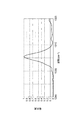
図4は、粗動スキャンにより得られたメタン(CH4)の波数1300cm−1付近における吸光度のグラフである。スキャンレートを1Hzとし、吸光度を10スキャン(10秒間)の平均値とした。図5は、NIST(National Institute of Standards and Technology)データベースより引用したメタンの波数1300cm−1付近における吸光度(規格化吸光度)のグラフである。 FIG. 4 is a graph of absorbance at a wave number of about 1300 cm −1 of methane (CH 4 ) obtained by coarse movement scan. The scan rate was 1 Hz, and the absorbance was an average of 10 scans (10 seconds). FIG. 5 is a graph of absorbance (normalized absorbance) in the vicinity of a wave number of 1300 cm −1 of methane, which is referred to from a National Institute of Standards and Technology (NIST) database.
図5の規格化吸光度のグラフに近いほど、吸光分析の精度が高いと考えられる。図4の吸光度のグラフは、図5の規格化吸光度のグラフと比較して、グラフ中央のピーク部分で鈍った形状となっており、ピーク部分について詳細な情報が得られていないことが分かる。これは、ステップ動作型である第一アクチュエータ51では、スキャン回数を稼ぐのに不向きであり、積算及び平均化によりS/Nを高め難いためである。
It is considered that the closer to the graph of the normalized absorbance in FIG. 5, the higher the accuracy of the absorbance analysis. Compared with the graph of the normalized absorbance of FIG. 5, the graph of the absorbance of FIG. 4 has a dull shape at the peak portion in the center of the graph, and it can be seen that detailed information is not obtained for the peak portion. This is because the step-operation type
図6は、微動スキャンにより得られたメタンの波数1300cm−1付近における吸光度のグラフである。微動スキャンの中心となる所定角度αは、粗動スキャンにより得られたピークの中心波長に対応する角度とした。つまり、入射角θを所定角度αとすることにより、波長可変光源10から出力されるレーザ光L3の波長が、粗動スキャンにより得られたピークの中心波長と重なる。この状態で、振り角を±2°として第二アクチュエータ52を周波数約700Hzで駆動した。吸光度を700スキャン(1秒間)の平均値とした。
FIG. 6 is a graph of absorbance at around 1300 cm −1 wavenumber of methane obtained by the fine movement scan. The predetermined angle α which is the center of the fine movement scan is an angle corresponding to the central wavelength of the peak obtained by the coarse movement scan. That is, by setting the incident angle θ to the predetermined angle α, the wavelength of the laser light L3 output from the variable wavelength
図4〜図6の比較により、波長可変光源10によれば、微動スキャンを行うことで、より精度の互い吸光分析が可能となり、粗動スキャンでは測定できなかったピーク部分の細かい形状まで測定できることが分かる。高速スキャンにより積算回数を増やしS/Nを高める手法自体は、MEMSアクチュエータを用いる従来の外部共振器型の波長可変光源でも可能である。
According to the comparison of FIGS. 4 to 6, according to the variable-
しかしながら、このような従来の波長可変光源は、第一アクチュエータ51のような粗動機構を有していない。このため、中心波長の変更ができず、限られた範囲(たとえば±50cm−1)の吸収ピークにしか図6のような分析結果を得ることができない。これに対して、波長可変光源10はハイブリッドアクチュエータを備えるため、1300cm−1付近のピークだけでなく、たとえば1350cm−1付近のピークに対しても同様の分析結果を得ることができる。
However, such a conventional tunable light source does not have a coarse movement mechanism like the
続いて、図7及び図8を参照して、本実施形態に係る波長可変光源の別の駆動方法について説明する。この駆動方法では、粗動スキャンの際、第一アクチュエータ51だけでなく第二アクチュエータ52も駆動する点で、上述の駆動方法と異なっている。具体的には、入射角θが1ステップでΔθずつ変化するように第一アクチュエータ51を周波数fで駆動すると共に、入射角θがΔθ/8を最大振幅として増減するように第二アクチュエータ52を周波数fで駆動する。
Subsequently, another driving method of the wavelength tunable light source according to the present embodiment will be described with reference to FIGS. 7 and 8. This driving method is different from the above-described driving method in that not only the
ここで、第二アクチュエータ52を停止させた状態で、第一アクチュエータ51のみを駆動した場合の問題について説明した後、第一アクチュエータ51及び第二アクチュエータ52を上述のように駆動する理由について説明する。図7は、第一アクチュエータのみを駆動した場合のタイミングチャートである。このタイミングチャートでは、(a)移動命令信号(すなわち、制御信号S1)、(b)回転量(すなわち、入射角θの変化量)、(c)回折格子の角速度(回転量の微分値)が示されている。
Here, after explaining the problem when only the
図7に示されるように、回転制御部12から出力される制御信号S1は、デューティー比がたとえば50%であり、t/2ごとに立ち上りおよび立ち下りを繰り返す矩形波の信号である。制御信号S1は、たとえば、周波数が100kHz(周期tが0.010msec)のパルス信号である。
As shown in FIG. 7, the control signal S1 output from the
上述のように、本実施形態では、第一アクチュエータ51はステッピングモータである。第一アクチュエータ51は、制御信号S1が1パルス入力される度に、最小移動ステップずつ回転する。第一アクチュエータ51は、制御信号S1をトリガとして回転する。本実施形態では、第一アクチュエータ51は、制御信号S1の立ち上りをトリガとして回転する。これにより、回折格子4の角速度が周期的に変化するように回折格子4が第二アクチュエータ52ごと回転駆動されて入射角θが変化する。角速度の変化の周期は、制御信号S1の周期tと等しくなる。
As described above, in the present embodiment, the
制御信号S1の立ち上りにおける角速度は、最小値ω1である。制御信号S1の立ち上りから約t/2経過後における角速度は、最大値ω2である。角速度の時間波形は、正弦波状であり、角速度がω1となる点から角速度が次にω1となる点まで、連続的に(滑らかに)変化する。言い換えると、角速度はω1とω2との間で周期的に変化する。 The angular velocity at the rise of the control signal S1 is the minimum value ω1. The angular velocity after a lapse of about t / 2 from the rise of the control signal S1 is the maximum value ω2. The time waveform of the angular velocity is sinusoidal, and changes continuously (smoothly) from the point where the angular velocity is ω1 to the point where the angular velocity is next ω1. In other words, the angular velocity changes periodically between ω1 and ω2.
角速度がこのように変化することにより、回転量は階段状に変化する。ここでは、回転量は、単調増加する。なお、単調増加とは減少傾向とならないことを意味し、広義の単調増加を意味する。図7(b)では、角速度が変化しない(角速度が一定である)理想的な場合の回転量が一点鎖線で示されている。 Due to this change in angular velocity, the amount of rotation changes in a step-like manner. Here, the amount of rotation monotonously increases. Note that monotonous increase means that it does not tend to decrease, and means monotonous increase in a broad sense. In FIG. 7B, the amount of rotation in the ideal case where the angular velocity does not change (the angular velocity is constant) is indicated by a one-dot chain line.
理想的な場合の回転駆動部5の動作は、正比例の直線動作である。第一アクチュエータ51の動作は、ステップ動作であるため、第一アクチュエータ51による回転量は、理想的な場合の回転量よりも小さくなったり大きくなったりを繰り返す。制御信号S1の立ち上り、及び制御信号S1の立ち上りから約t/2経過後において、第一アクチュエータ51による回転量と理想的な場合の回転量とは等しくなる。
The operation of the
このように、第一アクチュエータ51のみを駆動した場合、回折格子4の角速度にはムラが生じ、回折格子4の角速度は一定にはならない。このため、第一アクチュエータ51のみを駆動して波長掃引を行うと、回折格子4の角速度のムラにより波長変化速度のムラが発生する。この結果、吸光分析で得られる吸収曲線の吸収線幅が安定しなくなり、分析結果の精度を向上させることができない。
Thus, when only the
図8は、波長可変光源の別の駆動方法における回転量の時間波形である。図8の横軸は時間、縦軸は回転量となっている。図8には、1ステップでΔθずつ入射角θが変化するように、第一アクチュエータ51のみを周波数f(すなわち、周期1/f)で駆動した場合の回転量の時間波形が一点鎖線で示されている。Δθ/8を最大振幅として入射角θが増減するように、第二アクチュエータ52のみを周波数f(すなわち、周期1/f)で駆動した場合の回転量の時間波形が二点鎖線で示されている。第一アクチュエータ51による回転量の時間波形と、第二アクチュエータ52による回転量の時間波形との合成波形が実線で示されている。
FIG. 8 is a time waveform of the amount of rotation in another driving method of the wavelength tunable light source. The horizontal axis in FIG. 8 represents time, and the vertical axis represents the amount of rotation. In FIG. 8, the time waveform of the amount of rotation when only the
図8に示されるように、第一アクチュエータ51のみを駆動した場合に生じる回折格子4の角速度のムラが、第二アクチュエータ52により打ち消され、合成波形が略正比例の直線形状となる。したがって、この駆動方法によれば、回折格子4の角速度を略等速とすることができる。
As shown in FIG. 8, the unevenness of the angular velocity of the
続いて、図9及び図10を参照して、第一アクチュエータ51が超音波モータである場合についても説明する。図9は、超音波モータの場合に第一アクチュエータのみを駆動したときのタイミングチャートである。図10は、超音波モータの場合の別の駆動方法における回転量の時間波形である。図9に示されるように、超音波モータは、圧電素子を利用した圧電アクチュエータであり、制御信号S1の立ち上りおよび立ち下りに合わせて、圧電素子に与えられる電圧の極性を所定時間ごとに反転させることにより動作する。したがって、超音波モータの場合、角速度の変化の周期は、制御信号S1の周期tの1/2となり、超音波モータは、制御信号S1が1パルス入力される度に、ステッピングモータの2ステップ分を最小移動ステップとして回転する。
Subsequently, a case where the
そこで、超音波モータの場合は、図10に示されるように、入射角θが1ステップでΔθずつ変化するように第一アクチュエータ51を周波数fで駆動すると共に、入射角θがΔθ/16を最大振幅として増減するように第二アクチュエータ52を周波数2fで駆動する。これにより、第一アクチュエータ51のみを駆動した場合に生じる回折格子4の角速度のムラが、第二アクチュエータ52により打ち消され、合成波形が略正比例の直線形状となる。したがって、この駆動方法によれば、ステッピングモータの場合と同様に、回折格子4の角速度を略等速とすることができる。
Therefore, in the case of an ultrasonic motor, as shown in FIG. 10, the
以上説明したように、波長可変光源10では、回転駆動部5が、ステップ動作型である第一アクチュエータ51と、MEMSアクチュエータである第二アクチュエータ52とを有するハイブリッドアクチュエータである。このため、第一アクチュエータ51により広い波長範囲、及び高い波長制御性を維持しながら、第二アクチュエータ52により高速スキャンを行うことができる。
As described above, in the variable wavelength
また、第一アクチュエータ51の回転シャフト53の中心軸R1と、第二アクチュエータ52の可動部56の回転軸R2とが、同軸となっている。図11に示されるように、中心軸R1及び回転軸R2が同軸でなくオフセットしている場合、第一アクチュエータ51の回転角が変わると、外部共振器Eの長さLEが変わってしまう。具体的には、図11(a)よりも図11(b)では、第一アクチュエータ51の回転角が大きく、長さLEが短い。
Further, a central axis R1 of the
図11では、第二アクチュエータ52は停止した状態であり、第二アクチュエータ52の回転角は0°である。このため、長さLEは、第一アクチュエータ51の回転角により一意に定まる。しかしながら、第二アクチュエータ52の回転を考慮すると、長さLEは、第一アクチュエータ51の回転角と第二アクチュエータ52の回転角との組み合わせにより変動する。すなわち、所望の波長を実現する入射角θに対し、モード次数の異なる複数の長さLEが存在する。
In FIG. 11, the
例えば、第二アクチュエータ52を停止させ、第二アクチュエータ52の回転角を0°とした状態で第一アクチュエータ51を駆動させる粗動スキャン中と、第一アクチュエータ51を所定の回転角で停止させた状態で第二アクチュエータ52を回転させる微動スキャン中とでは、入射角θが等しくても長さLEが互いに異なり、モード次数が異なる結果、波長が異なってしまう場合がある。
For example, the
このように、粗動スキャン中と微動スキャン中とでモード次数が異なる結果、波長の再現性及び安定性が損なわれる懼れがある。これに対して、波長可変光源10では、第一アクチュエータ51の中心軸R1と第二アクチュエータ52の回転軸R2とが、同軸となっている。これにより、所望の波長を実現する入射角θに対し、長さLEが一意に定まる結果、波長の再現性及び安定性が保たれる。なお、所望の波長を実現する入射角θに対し、長さLEが一意に定まれば、入射角θに応じて長さLEが変化しても問題はないが、波長可変光源10における長さLEは全ての入射角θに対して一定に保たれている。
As described above, as a result of the difference in the mode order between the coarse movement scan and the fine movement scan, the wavelength reproducibility and stability may be impaired. On the other hand, in the variable wavelength
波長可変光源10の駆動方法は、回転駆動部5のうち第一アクチュエータ51のみ駆動するステップと、第二アクチュエータ52のみを駆動するステップと、を含んでいる。これにより、吸光分析装置100では、たとえば第一アクチュエータ51により広い波長範囲で粗動スキャンを行った後、より詳細に分析すべき波長範囲を絞り込み、絞り込んだ波長範囲を第二アクチュエータ52により高速で微動スキャンすることができる。この結果、分析可能な波長範囲を広く維持しながら、任意の波長範囲における分析の精度を高めることができる。
The driving method of the variable wavelength
波長可変光源10の別の駆動方法では、第一アクチュエータ51がステッピングモータの場合、粗動スキャンの際、入射角θが1ステップでΔθずつ変化するように第一アクチュエータ51を周波数fで駆動すると共に、入射角θがΔθ/8を最大振幅として増減するように第二アクチュエータ52を周波数fで駆動する。また、第一アクチュエータ51が超音波モータの場合、粗動スキャンの際、入射角θが1ステップでΔθずつ変化するように第一アクチュエータ51を周波数fで駆動すると共に、入射角θがΔθ/16を最大振幅として増減するように第二アクチュエータ52を周波数2fで駆動する。
In another driving method of the variable wavelength
この駆動方法では、ステップ動作型である第一アクチュエータ51を用いた場合に生じる角速度のムラを、第二アクチュエータ52により打ち消すことができる。これにより、レーザ光L3の波長変化速度の変動が抑制される。この結果、吸光分析で得られる吸収曲線の吸収線幅が安定し、分析結果の精度を向上させることができる。
In this driving method, the
1…半導体レーザ、2…レーザ駆動部、4…回折格子、5…回転駆動部、10…波長可変光源、51…第一アクチュエータ、52…第二アクチュエータ、53…回転シャフト、55…支持部、56…可動部、57…連結部、E…外部共振器、L1…パルス光、L2…回折光、R1…中心軸、R2…回転軸、θ…入射角。
DESCRIPTION OF
Claims (4)
前記半導体レーザと共に外部共振器を構成する回折格子であって、前記半導体レーザから出射された前記パルス光が入射し、前記パルス光のうち入射角に応じた波長の光を前記半導体レーザに帰還させる回折格子と、
前記回折格子を回転駆動して前記入射角を変化させる回転駆動部と、を備え、
前記回転駆動部は、
回転シャフトを含み、ステップ動作型である第一アクチュエータと、
支持部と、前記回折格子が設けられた可動部と、前記可動部を前記支持部に回転可能に連結する連結部と、を含む第二アクチュエータと、を有し、
前記第二アクチュエータは、前記可動部の回転軸が前記回転シャフトの中心軸と一致するように前記回転シャフトに取り付けられている、波長可変光源。 A semiconductor laser for emitting pulsed light;
A diffraction grating constituting an external resonator together with the semiconductor laser, wherein the pulse light emitted from the semiconductor laser is incident, and light of a wavelength according to an incident angle of the pulse light is returned to the semiconductor laser A diffraction grating,
And a rotational drive unit that rotates the diffraction grating to change the incident angle.
The rotational drive unit is
A first actuator including a rotating shaft and being step-operated,
A second actuator including a support portion, a movable portion provided with the diffraction grating, and a connecting portion rotatably connecting the movable portion to the support portion;
The variable wavelength light source according to claim 1, wherein the second actuator is attached to the rotating shaft such that a rotating shaft of the movable portion coincides with a central axis of the rotating shaft.
前記第一アクチュエータを駆動するステップと、
前記第一アクチュエータを停止させた状態で、前記第二アクチュエータを駆動するステップと、を含む、波長可変光源の駆動方法。 The method of driving a variable wavelength light source according to claim 1,
Driving the first actuator;
Driving the second actuator in a state in which the first actuator is stopped.
前記第一アクチュエータとして、ステッピングモータを用い、
前記入射角が1ステップで第一角度ずつ変化するように前記第一アクチュエータを第一周波数で駆動すると共に、前記入射角が第二角度を最大振幅として増減するように前記第二アクチュエータを第二周波数で駆動し、
前記第一周波数と前記第二周波数とは互いに等しく、前記第一角度をΔθとすると、前記第二角度はΔθ/8である、波長可変光源の駆動方法。 The method of driving a variable wavelength light source according to claim 1,
A stepping motor is used as the first actuator,
The first actuator is driven at a first frequency such that the incident angle changes by a first angle in one step, and the second actuator is increased or decreased such that the incident angle increases or decreases with a second angle. Drive at frequency
A method of driving a tunable light source, wherein the first frequency and the second frequency are equal to each other, and the first angle is Δθ, the second angle is Δθ / 8.
前記第一アクチュエータとして、超音波モータを用い、
前記入射角が1ステップで第一角度ずつ変化するように前記第一アクチュエータを第一周波数で駆動すると共に、前記入射角が第二角度を最大振幅として増減するように前記第二アクチュエータを第二周波数で駆動し、
前記第一周波数をfとすると、前記第二周波数は2fであり、前記第一角度をΔθとすると、前記第二角度はΔθ/16である、波長可変光源の駆動方法。 The method of driving a variable wavelength light source according to claim 1,
An ultrasonic motor is used as the first actuator,
The first actuator is driven at a first frequency such that the incident angle changes by a first angle in one step, and the second actuator is increased or decreased such that the incident angle increases or decreases with a second angle. Drive at frequency
A driving method of a tunable light source, where the first frequency is f, the second frequency is 2f, and the first angle is Δθ, the second angle is Δθ / 16.
Priority Applications (1)
| Application Number | Priority Date | Filing Date | Title |
|---|---|---|---|
| JP2016015539A JP6510990B2 (en) | 2016-01-29 | 2016-01-29 | Wavelength variable light source and driving method thereof |
Applications Claiming Priority (1)
| Application Number | Priority Date | Filing Date | Title |
|---|---|---|---|
| JP2016015539A JP6510990B2 (en) | 2016-01-29 | 2016-01-29 | Wavelength variable light source and driving method thereof |
Publications (2)
| Publication Number | Publication Date |
|---|---|
| JP2017135314A JP2017135314A (en) | 2017-08-03 |
| JP6510990B2 true JP6510990B2 (en) | 2019-05-08 |
Family
ID=59503743
Family Applications (1)
| Application Number | Title | Priority Date | Filing Date |
|---|---|---|---|
| JP2016015539A Expired - Fee Related JP6510990B2 (en) | 2016-01-29 | 2016-01-29 | Wavelength variable light source and driving method thereof |
Country Status (1)
| Country | Link |
|---|---|
| JP (1) | JP6510990B2 (en) |
Cited By (1)
| Publication number | Priority date | Publication date | Assignee | Title |
|---|---|---|---|---|
| JP2017135315A (en) * | 2016-01-29 | 2017-08-03 | 浜松ホトニクス株式会社 | Tunable light source |
Families Citing this family (4)
| Publication number | Priority date | Publication date | Assignee | Title |
|---|---|---|---|---|
| JP6943675B2 (en) * | 2017-08-10 | 2021-10-06 | 浜松ホトニクス株式会社 | External resonance type laser module, analyzer, external resonance type laser module drive method, program |
| JP7738381B2 (en) | 2019-03-28 | 2025-09-12 | セイコーエプソン株式会社 | Frequency shifter type optical modulator and laser Doppler measurement device |
| JP7302321B2 (en) | 2019-06-18 | 2023-07-04 | セイコーエプソン株式会社 | Electronic watch, movement, motor control circuit, and electronic watch control method |
| CN116804588A (en) * | 2022-03-16 | 2023-09-26 | 北京科益虹源光电技术有限公司 | Grating diffraction efficiency measuring device |
Family Cites Families (14)
| Publication number | Priority date | Publication date | Assignee | Title |
|---|---|---|---|---|
| JPS5812385A (en) * | 1981-06-26 | 1983-01-24 | Fujitsu Ltd | Emitting light wave length sweep system of wave length variable laser |
| ATE50864T1 (en) * | 1985-10-16 | 1990-03-15 | British Telecomm | FABRY-PEROT INTERFEROMETER. |
| JPH06289305A (en) * | 1993-04-01 | 1994-10-18 | Olympus Optical Co Ltd | Scanning unit |
| JPH10313146A (en) * | 1997-05-14 | 1998-11-24 | Anritsu Corp | Wavelength variable light source device |
| JP3511359B2 (en) * | 1998-02-27 | 2004-03-29 | 三菱電機株式会社 | Laser processing equipment |
| JP2002190642A (en) * | 2000-12-21 | 2002-07-05 | Ando Electric Co Ltd | Variable wavelength light source |
| JP4557730B2 (en) * | 2005-01-28 | 2010-10-06 | アンリツ株式会社 | Optical spectrum analyzer |
| JP2008270585A (en) * | 2007-04-23 | 2008-11-06 | Fujifilm Corp | Optical semiconductor device, wavelength tunable light source and optical tomographic image acquisition apparatus using the optical semiconductor device |
| JP2011170140A (en) * | 2010-02-19 | 2011-09-01 | Seiko Epson Corp | Image forming apparatus |
| WO2011156818A2 (en) * | 2010-06-11 | 2011-12-15 | Block Engineering, Llc | Qcl spectroscopy system and applications therefor |
| JP5867691B2 (en) * | 2011-10-13 | 2016-02-24 | 横河電機株式会社 | Laser gas analyzer |
| JP5899146B2 (en) * | 2013-03-26 | 2016-04-06 | 日本電信電話株式会社 | Multi-wavelength semiconductor laser light source |
| JP5848791B2 (en) * | 2013-08-06 | 2016-01-27 | 株式会社東芝 | Exhalation diagnostic device |
| JP6062355B2 (en) * | 2013-12-13 | 2017-01-18 | 三菱日立パワーシステムズ株式会社 | Gas analysis method and gas analyzer |
-
2016
- 2016-01-29 JP JP2016015539A patent/JP6510990B2/en not_active Expired - Fee Related
Cited By (1)
| Publication number | Priority date | Publication date | Assignee | Title |
|---|---|---|---|---|
| JP2017135315A (en) * | 2016-01-29 | 2017-08-03 | 浜松ホトニクス株式会社 | Tunable light source |
Also Published As
| Publication number | Publication date |
|---|---|
| JP2017135314A (en) | 2017-08-03 |
Similar Documents
| Publication | Publication Date | Title |
|---|---|---|
| JP6510990B2 (en) | Wavelength variable light source and driving method thereof | |
| US10928313B2 (en) | Optical absorption spectroscopy based gas analyzer systems and methods | |
| CN103201603B (en) | Interferometer and Fourier transform spectroscopic analysis device | |
| Wysocki et al. | Widely tunable mode-hop free external cavity quantum cascade laser for high resolution spectroscopic applications | |
| Spagnolo et al. | Mid-infrared fiber-coupled QCL-QEPAS sensor | |
| JP6943675B2 (en) | External resonance type laser module, analyzer, external resonance type laser module drive method, program | |
| JP6676389B2 (en) | Tunable light source | |
| CN102195233B (en) | Laser diode structure with reduced inference signal | |
| CN103562704B (en) | Adaptable cell design for a spectroscopy apparatus | |
| US9131877B2 (en) | Laser apparatus and photoacoustic apparatus | |
| JP2011187947A (en) | Wavelength swept light source apparatus and imaging device employing the same | |
| Jiménez et al. | Narrow-line external cavity diode laser micro-packaging in the NIR and MIR spectral range | |
| CN113671465B (en) | Laser radar transmitting device, laser radar and detection method | |
| CN115603172B (en) | Fast tuning small Littman structure external cavity laser | |
| US20160336720A1 (en) | Microelectromechanical system for tuning lasers | |
| CN113412561A (en) | Method and apparatus for characterizing a laser gain chip | |
| Bayrakli | External cavity diode laser-based off-axis cavity enhanced absorption spectroscopy in the spectral range between 1000 nm and 1620 nm for trace gas measurements | |
| JP5121150B2 (en) | Tunable laser light source | |
| JP5000277B2 (en) | Terahertz electromagnetic wave generator and terahertz electromagnetic wave detector | |
| US7406218B2 (en) | FBG sensor system | |
| Luo et al. | Study of a periodic spectral fluctuation existing in a fibered optical feedback cavity-enhanced absorption spectroscopy (OF-CEAS) | |
| Haertelt et al. | Advances of MOEMS-based external cavity QCLs | |
| US20250102358A1 (en) | Spectroscopic analyzer | |
| Phillips et al. | Measurement of broad absorption features using a tunable external cavity quantum cascade laser | |
| Ostendorf et al. | MOEMS EC-QCL for real-time identification of chemical compounds |
Legal Events
| Date | Code | Title | Description |
|---|---|---|---|
| A621 | Written request for application examination |
Free format text: JAPANESE INTERMEDIATE CODE: A621 Effective date: 20180905 |
|
| A977 | Report on retrieval |
Free format text: JAPANESE INTERMEDIATE CODE: A971007 Effective date: 20190328 |
|
| TRDD | Decision of grant or rejection written | ||
| A01 | Written decision to grant a patent or to grant a registration (utility model) |
Free format text: JAPANESE INTERMEDIATE CODE: A01 Effective date: 20190402 |
|
| A61 | First payment of annual fees (during grant procedure) |
Free format text: JAPANESE INTERMEDIATE CODE: A61 Effective date: 20190405 |
|
| R150 | Certificate of patent or registration of utility model |
Ref document number: 6510990 Country of ref document: JP Free format text: JAPANESE INTERMEDIATE CODE: R150 |
|
| R250 | Receipt of annual fees |
Free format text: JAPANESE INTERMEDIATE CODE: R250 |
|
| LAPS | Cancellation because of no payment of annual fees |