JP6504620B2 - Chamfering tool - Google Patents
Chamfering tool Download PDFInfo
- Publication number
- JP6504620B2 JP6504620B2 JP2017004213A JP2017004213A JP6504620B2 JP 6504620 B2 JP6504620 B2 JP 6504620B2 JP 2017004213 A JP2017004213 A JP 2017004213A JP 2017004213 A JP2017004213 A JP 2017004213A JP 6504620 B2 JP6504620 B2 JP 6504620B2
- Authority
- JP
- Japan
- Prior art keywords
- chamfering tool
- body portion
- groove
- chamfering
- main body
- Prior art date
- Legal status (The legal status is an assumption and is not a legal conclusion. Google has not performed a legal analysis and makes no representation as to the accuracy of the status listed.)
- Active
Links
Images




Landscapes
- Grinding And Polishing Of Tertiary Curved Surfaces And Surfaces With Complex Shapes (AREA)
Description
本発明は、木材等の角部を削る面取り具に関するものである。 TECHNICAL FIELD The present invention relates to a chamfering tool for cutting corners of wood or the like.
一般に、木材を加工し、木工製品を製作する際に、のこぎり等で切断したままの板材や角柱を使用すると、さわり心地が悪かったり、ささくれ等により怪我をする虞れがある。このため、鉋や棒ヤスリで角部を削ったり、紙ヤスリのみを用いたりして面取り作業を行っている。 Generally, when processing wood and manufacturing woodworking products, using plate materials and prisms as they are cut with a saw or the like may cause discomfort due to touching feeling or tears. For this reason, chamfering work is performed by scraping the corners with a scissors or a stick file, or using only a sandpaper.
しかし、鉋や棒ヤスリで均一な面取り作業を行うには、鉋や棒ヤスリがぶれないような一定の角度で、力加減を保持しながら作業を行う必要があり、家庭での日用大工程度の素人の技術では、見栄えの良い面取り作業を行うことは難しい。また、紙ヤスリのみを用いて面取り作業を行った場合も、加減の調整が難しいため面取りした面が不均一となる。 However, in order to perform uniform chamfering work with scissors and stick files, it is necessary to work while holding the amount of force at a certain angle so that the stick and stick files do not shake It is difficult to do a good-looking chamfering operation with the amateur technique of In addition, even when chamfering work is performed using only a sandpaper, the chamfered surface becomes uneven because it is difficult to adjust the degree of change.
そこで、例えば特許文献1に示すような木材の面取り専用の金属刃を備えたばり取り具を使用すれば、切削面を正確に一定角度に加工できる。汎用の鉋や棒ヤスリを使用した場合に比較すると、見栄えの良い面取り作業を行うことができる。
Therefore, for example, if a deburring tool provided with a metal blade dedicated to chamfering of wood as shown in
しかし、特許文献1のばり取り具は、鉋の一種であって、特殊な形状の刃を使用しており、刃が摩耗すれば刃を外し、研ぎ直した後に再度、刃の出刃を調整をする必要がある。
However, the deburring tool of
この特殊な形状の刃の研ぎ直しは、熟練の技術が必要であると共に、刃の微妙な出刃調整も専門家でないと到底不可能である。刃の研ぎ方、出刃調整は研削する木材の種類によって変化させる繊細な作業であり、これらの調整作業ができないと、ばり取り具として使用することが難しい。従って、特許文献1のばり取り具は、素人では使用することが困難であるという問題がある。
The regrinding of this special-shaped blade requires skill and skill, and it is impossible without an expert to adjust the blade's subtle protrusion. The method of sharpening the blade and adjusting the outgoing blade are delicate operations that are changed according to the type of wood to be ground, and if these adjusting operations can not be performed, it is difficult to use as a deburring tool. Therefore, there is a problem that the deburring tool of
更に、特許文献1の面取り具は刃を使用しているために、面取りの対象が金属材や硬い合成樹脂材に対しては適用が困難であるという問題もある。
Furthermore, since the chamfering tool of
本発明の目的は、上述の課題を解消し、家庭においても簡便に木材等の角部に対する正確な面取り作業を行うことのできる面取り具を提供することにある。 An object of the present invention is to provide a chamfering tool capable of solving the above-mentioned problems and easily performing accurate chamfering work on corners of wood or the like even at home.
上記目的を達成するための本発明に係る面取り具は、上面に開き角が略90度から成る2つの斜面部をV字溝状に配置した本体部を有する面取り具であって、 前記2つの斜面部は主溝部を介して連続しており、前記主溝部の両側には、前記本体部の底面から上方に起立する一対の側面部に設けた副溝部が連続し、前記主溝部及び前記副溝部に細条の研磨シートを貼り付け可能としたことを特徴とする。
また、本発明に係る面取り具は、上面に開き角が略90度から成る2つの斜面部をV字溝状に配置した本体部を有する面取り具であって、前記2つの斜面部は主溝部を介して連続しており、該主溝部に細条の研磨シートを貼り付け可能とし、矩形状である前記2つの斜面部の短辺の長さが異なるようにされていることを特徴とする。
A chamfering tool according to the present invention for achieving the above object is a chamfering tool having a main body portion in which two sloped portions having an opening angle of approximately 90 degrees are arranged in a V-shaped groove shape on the upper surface, The sloped portion is continuous via the main groove portion, and on both sides of the main groove portion, sub groove portions provided in a pair of side surface portions rising upward from the bottom surface of the main body portion are continuous, the main groove portion and the sub groove portion It is characterized in that a strip abrasive sheet can be attached to the groove .
The chamfering tool according to the present invention is a chamfering tool having a main body portion in which two sloped portions having an opening angle of approximately 90 degrees are arranged in a V-shaped groove shape on the upper surface, and the two sloped portions are main grooved portions. Continuous between the main groove portion and the main groove portion, and the lengths of the short sides of the two slope portions which are rectangular are made different from each other. .
本発明に係る面取り具によれば、溝底の貼付部に貼り付けた研磨シートを用いて、木材等の角度を簡便にかつ正確に面取りを行うことができる。 ADVANTAGE OF THE INVENTION According to the chamfering tool which concerns on this invention, angle of wood etc. can be chamfered simply and correctly using the abrasive sheet stuck on the sticking part of the groove bottom.
本発明を図示の実施例に基づいて詳細に説明する。
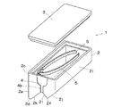
図1は本実施例における丸面取り用の面取り具1の斜視図、図2は側面図である。
The present invention will be described in detail based on the illustrated embodiments.
FIG. 1 is a perspective view of a
本体部2は内部が中空状とされており、本体部2の底面には、平面状の底板3が開閉自在に取り付けられている。本体部2の内部には、後述する紙ヤスリ等の研磨シートが収納できるようにされている。
The inside of the
本体部2及び底板3は合成樹脂から成り、合成樹脂以外にも金属等の材料を適宜に用いてもよい。また、底板3の端部に押圧片を設けて、本体部2の底面に押圧片の部分が嵌り込む構造にしてもよい。この押圧片を押すことで、本体部2に係止されていた底板3を容易に本体部2から離脱させることが可能となる。
The
本体部2の底面を水平面と一致させた状態で、本体部2の上面側に水平方向に対してそれぞれ略45度ずつ傾斜した斜面部2a、2bが開き角が略90度のV字溝状に配置されている。これらの斜面部2a、2bはそれぞれ矩形状であり、溝底の貼付部4を介して連続している。また、本体部2の長手方向の両側には側面部2cが設けられている。
With the bottom surface of the
貼付部4は、後述する研磨シートを貼り付けるため、断面円弧状に湾曲された浅い主溝部4aと、この主溝部4aの長手方向の両側に連続し、側面部2cに設けた一対の浅い副溝部4bとから構成されている。そして、副溝部4bは上方の主溝部4aと同幅の側溝と、下方の半円状の側溝とから構成されている。なお、側面部2cは本体部2の底面の短辺から上方に起立している。
The
斜面部2aは本体部2の底面の一方の長辺から上方に起立する長側面部2eと陵線2dを介して連続しており、斜面部2bは斜面部2aと平行する矩形状の斜面部2gと陵線2fを介して連続している。斜面部2bと斜面部2gとは角90度で連続され、斜面部2gは本体部2の底面の他方の長辺から上方に起立する長側面部2iと陵線2hを介して連続している。なお、陵線2d、2f、2hは若干の丸みを帯びている。
The
斜面部2gと側面部2c間の陵線2jの長さは、斜面部2aと側面部2c間の陵線2kよりも短く、斜面部2bと側面部2c間の陵線2lよりも長い。寸法的には、例えば本体部2の長手方向の長さが70mm、短手方向の長さが30mm、長側面部2eの高さが30mm程度であり、陵線2j、2k、2lの長さがそれぞれ、13mm、16mm、8.5mm程度である。この面取り具1の大きさは、被面取り材の板厚等に応じて適宜の大きさのものを採用することができる。
The length of the
貼付部4には、紙ヤスリ等から成る細条の研磨シート5が貼り付け可能とされている。この研磨シートは貼付部4の溝幅と幅が略一致し、例えば幅4mm、長さは例えば120mm程度である。また、研磨シート5は、表面が砥粒を塗布した研磨層とされた紙又は不織布又は布体であり、裏面が粘着剤を塗布した粘着層とされ、この粘着層上に剥離テープが貼付されている。
A strip
使用時には、研磨シート5から剥離テープを剥がして、貼付部4に沿って図3に示すように研磨シート5の粘着層を貼り付ける。貼付部4の浅い主溝部4aに研磨シート5が嵌まり込むため、使用時に研磨シート5の短手方向の縁部から引っかかることはなく、貼付部4から研磨シート5がずれたりすることはない。
At the time of use, the peeling tape is peeled off from the
また、研磨シート5は主溝部4aの長さよりも大きくされており、研磨シート5の端部5aは一対の側面部2cの副溝部4bに至るまで貼り付けることで、研磨シート5の端部5aが被面取り材に引っかかって貼付部4から剥れる虞れもない。
Further, the
また、図4に示すように矩形状の底板3を開閉できる本体部2の内部には、予備の研磨シート5や番手の異なる研磨シート5等を収納しておくことができる。
In addition, as shown in FIG. 4, spare
面取り作業に際しては、図5に示すように斜面部2a、2bを木材Wの上端の直角面に当接させ、図示する矢印の方向に摺動させる。これにより、研磨シート5の研磨層が直角面の角部W1に対し45度の角度で当接し、円弧状に貼られた研磨シート5により角部W1を丸面状に面取りすることができる。
At the time of the chamfering operation, as shown in FIG. 5, the
なお、一般に流通する木製の板材には、例えば9mm、12mm、15mm、18mm、20mm、25mm、・・・のように板厚の規格が存在する。9mm以下の板厚の板材も存在するが、板厚9mm以下の板材は比較的少なく、圧倒的に9mm以上の板材が多い。 In addition, the standard of board thickness exists, for example like 9 mm, 12 mm, 15 mm, 18 mm, 20 mm, 25 mm, ... in the board material of the wood generally distribute | circulating. There are plate materials with a thickness of 9 mm or less, but there are relatively few plates with a thickness of 9 mm or less, and there are a large number of plates with a thickness of 9 mm or more.
そこで、本実施例における面取り具1は、例えば汎用的な板厚である板厚9mmの木材Wを作業台上に載置し、安定した状態で面取り作業できるようするために、斜面部2bの陵線2lは前述したように9mmとすることで、斜面部2gも作業台上を摺動させることが可能である。
Therefore, the
なお、斜面部2a、2bの幅が異なるようにされているので、木材Wの厚み側の端縁に短い幅の斜面部2bを当接することにより、作業台上に載置した厚みの小さな木材Wに対しても面取りが可能となる。
In addition, since the width of the
なお、使用目的に応じて研磨シート5を粗い番手の研磨シート5から細かな番手の研磨シートSに貼り直すなどして、適切な番手の研磨シート5を選択することにより、効率的かつ綺麗な面取り作業を行うことができる。
In addition, depending on the purpose of use, the
また、研磨シート5が摩耗したり、異なる番手のものに取り換える場合には、副溝部4bの半円状の溝部に突出して貼られている研磨シート5の端部から爪等で剥して、新たな研磨シート5を貼り換える。従って、簡便に新たな研磨層により面取り作業を再開することができる。
In addition, when the
なお、実施例においては、面取りの対象を木材としたが、研磨シート5は砥粒による研磨層を有しているので、必要に応じて金属材や合成樹脂材から成る被面取り材の角部に対し、面取りを行うことが可能である。
In the embodiment, although the target of chamfering is wood, since the polishing
図6は平面取り用の面取り具1’の側面図であり、貼付部4の主溝部4a’は底板3と平行する平面状とされている。従って、主溝部4a’に貼り付けた研磨シート5の研磨層は平面状となる。
FIG. 6 is a side view of the chamfering tool 1 'for planarizing, and the
このため、面取り作業に際しては、研磨シート5が角部W1に対し45度の角度で平面状に当接し、角部W1は平面状に面取りされる。
For this reason, at the time of the chamfering operation, the polishing
また、副溝部4bについては、丸面取り用の面取り具では図1に示すように半円状である丸状の側溝を形成し、平面取り用では図6に示すように角状の側溝を形成すれば、これらの側溝の形状の相異から、遠目からでも平面状の面取り具なのか丸面状の面取り具なのか瞬時に判断することができる。
In addition, with respect to the
このように、面取り具1、1’を用いることで、素人であっても、簡便にかつ正確に被面取り材に対して面取りを行うことができる。
As described above, by using the
1、1’ 面取り具
2 本体部
2a、2b、2g 斜面部
2c 側面部
2d、2f、2h、2j、2k、2l 陵線
3 底部
4 貼付部
4a 主溝部
4b 副溝部
5 研磨シート
W 木材
W1 角部
1, 1 '
2a, 2b,
Claims (6)
前記2つの斜面部は主溝部を介して連続しており、
前記主溝部の両側には、前記本体部の底面から上方に起立する一対の側面部に設けた副溝部が連続し、前記主溝部及び前記副溝部に細条の研磨シートを貼り付け可能としたことを特徴とする面取り具。 A chamfering tool having a main body portion in which two slope portions having an opening angle of about 90 degrees are arranged in a V-shaped groove shape on the upper surface,
The two slopes are continuous through the main groove,
On both sides of the main groove portion, sub groove portions provided in a pair of side surface portions rising upward from the bottom surface of the main body portion are continuous, and it is possible to attach a strip polishing sheet to the main groove portion and the sub groove portion. Chamfer tool characterized by.
前記2つの斜面部は主溝部を介して連続しており、該主溝部に細条の研磨シートを貼り付け可能とし、
矩形状である前記2つの斜面部の短辺の長さが異なるようにされていることを特徴とする面取り具。 A chamfering tool having a main body portion in which two slope portions having an opening angle of about 90 degrees are arranged in a V-shaped groove shape on the upper surface,
The two slopes are continuous through the main groove, and a strip abrasive sheet can be attached to the main groove,
A chamfering tool characterized in that the lengths of the short sides of the two slopes which are rectangular are different .
Priority Applications (1)
| Application Number | Priority Date | Filing Date | Title |
|---|---|---|---|
| JP2017004213A JP6504620B2 (en) | 2017-01-13 | 2017-01-13 | Chamfering tool |
Applications Claiming Priority (1)
| Application Number | Priority Date | Filing Date | Title |
|---|---|---|---|
| JP2017004213A JP6504620B2 (en) | 2017-01-13 | 2017-01-13 | Chamfering tool |
Publications (2)
| Publication Number | Publication Date |
|---|---|
| JP2018111178A JP2018111178A (en) | 2018-07-19 |
| JP6504620B2 true JP6504620B2 (en) | 2019-04-24 |
Family
ID=62911631
Family Applications (1)
| Application Number | Title | Priority Date | Filing Date |
|---|---|---|---|
| JP2017004213A Active JP6504620B2 (en) | 2017-01-13 | 2017-01-13 | Chamfering tool |
Country Status (1)
| Country | Link |
|---|---|
| JP (1) | JP6504620B2 (en) |
Families Citing this family (1)
| Publication number | Priority date | Publication date | Assignee | Title |
|---|---|---|---|---|
| CN114454027B (en) * | 2022-02-28 | 2023-01-10 | 宿迁澳中玻璃股份有限公司 | A support platform for large glass processing |
Family Cites Families (10)
| Publication number | Priority date | Publication date | Assignee | Title |
|---|---|---|---|---|
| JPS53141592U (en) * | 1977-04-15 | 1978-11-08 | ||
| JPS5837098B2 (en) * | 1977-08-16 | 1983-08-13 | 哲夫 頼 | finishing machine |
| JPS5520449Y2 (en) * | 1977-09-21 | 1980-05-16 | ||
| JPS5969821U (en) * | 1982-11-04 | 1984-05-11 | 日本電気株式会社 | Deburring tool |
| JPH01114229U (en) * | 1988-01-29 | 1989-08-01 | ||
| US5895316A (en) * | 1996-09-03 | 1999-04-20 | Williams; John W. | Dry-wall corner sander |
| JPH10235565A (en) * | 1997-02-26 | 1998-09-08 | Hoorai:Kk | Grinding tool and grinding sheet holding tool |
| US6439983B1 (en) * | 2000-11-17 | 2002-08-27 | Pro-Line, Inc. | Sanding and cleaning device for drywall bullnose cornerbeads |
| JP2004082241A (en) * | 2002-08-26 | 2004-03-18 | Kato Seiko:Kk | Work supporting tool in chamfering grinding device |
| US20070173186A1 (en) * | 2006-01-26 | 2007-07-26 | Esito International Llc. | Grinder for windshield wipers |
-
2017
- 2017-01-13 JP JP2017004213A patent/JP6504620B2/en active Active
Also Published As
| Publication number | Publication date |
|---|---|
| JP2018111178A (en) | 2018-07-19 |
Similar Documents
| Publication | Publication Date | Title |
|---|---|---|
| US6997795B2 (en) | Versatile manual scissor sharpener | |
| US2765593A (en) | Sanding block | |
| US8597087B2 (en) | Universal abrasive sheet | |
| US9511480B1 (en) | Dropless drywall sanding block | |
| JP6504620B2 (en) | Chamfering tool | |
| US20080039001A1 (en) | Knife Sharpener | |
| US20140256237A1 (en) | Drywall Sander | |
| JP2010260160A (en) | Blade sharpener | |
| US5287625A (en) | Sandpaper cutting guide | |
| US3517462A (en) | Reducing and roughing tools | |
| US9168600B2 (en) | Rasp for smoothing irregularly shaped surfaces | |
| US3513602A (en) | Clipper blade sharpener | |
| JP5578631B2 (en) | Sharpening tools | |
| JP3246952U (en) | Blade sharpening device | |
| JP6770731B2 (en) | Polishing sheet | |
| JP2005334577A (en) | Chopping board with kitchen knife sharpener | |
| TWM493439U (en) | Knife grinder | |
| US2434141A (en) | Sharpening device | |
| KR200465221Y1 (en) | knife sharpener with grinding tip | |
| JP2009219793A (en) | Method for sewing stingray skin and sewn products | |
| JPH061328Y2 (en) | Sharpening | |
| JP3030597U (en) | Kitchen knife storage tool with blade sharpening function | |
| JP4145130B2 (en) | Wax scraper processing jig | |
| JPH0530601B2 (en) | ||
| JP2009148871A (en) | Grinding tool |
Legal Events
| Date | Code | Title | Description |
|---|---|---|---|
| A977 | Report on retrieval |
Free format text: JAPANESE INTERMEDIATE CODE: A971007 Effective date: 20181212 |
|
| A131 | Notification of reasons for refusal |
Free format text: JAPANESE INTERMEDIATE CODE: A131 Effective date: 20181218 |
|
| A521 | Request for written amendment filed |
Free format text: JAPANESE INTERMEDIATE CODE: A523 Effective date: 20190215 |
|
| TRDD | Decision of grant or rejection written | ||
| A01 | Written decision to grant a patent or to grant a registration (utility model) |
Free format text: JAPANESE INTERMEDIATE CODE: A01 Effective date: 20190226 |
|
| A61 | First payment of annual fees (during grant procedure) |
Free format text: JAPANESE INTERMEDIATE CODE: A61 Effective date: 20190320 |
|
| R150 | Certificate of patent or registration of utility model |
Ref document number: 6504620 Country of ref document: JP Free format text: JAPANESE INTERMEDIATE CODE: R150 |
|
| R250 | Receipt of annual fees |
Free format text: JAPANESE INTERMEDIATE CODE: R250 |
|
| R250 | Receipt of annual fees |
Free format text: JAPANESE INTERMEDIATE CODE: R250 |
|
| R250 | Receipt of annual fees |
Free format text: JAPANESE INTERMEDIATE CODE: R250 |
|
| R250 | Receipt of annual fees |
Free format text: JAPANESE INTERMEDIATE CODE: R250 |
|
| R250 | Receipt of annual fees |
Free format text: JAPANESE INTERMEDIATE CODE: R250 |