JP6495857B2 - Construction machinery - Google Patents
Construction machinery Download PDFInfo
- Publication number
- JP6495857B2 JP6495857B2 JP2016070130A JP2016070130A JP6495857B2 JP 6495857 B2 JP6495857 B2 JP 6495857B2 JP 2016070130 A JP2016070130 A JP 2016070130A JP 2016070130 A JP2016070130 A JP 2016070130A JP 6495857 B2 JP6495857 B2 JP 6495857B2
- Authority
- JP
- Japan
- Prior art keywords
- boom
- pressure
- control valve
- pilot pressure
- construction machine
- Prior art date
- Legal status (The legal status is an assumption and is not a legal conclusion. Google has not performed a legal analysis and makes no representation as to the accuracy of the status listed.)
- Active
Links
- 238000010276 construction Methods 0.000 title claims description 78
- 230000001133 acceleration Effects 0.000 claims description 58
- 238000009412 basement excavation Methods 0.000 claims description 40
- 238000012937 correction Methods 0.000 description 14
- 230000007423 decrease Effects 0.000 description 12
- 238000010586 diagram Methods 0.000 description 11
- 238000006243 chemical reaction Methods 0.000 description 10
- 238000000034 method Methods 0.000 description 10
- 230000008569 process Effects 0.000 description 10
- 230000033001 locomotion Effects 0.000 description 6
- 230000008859 change Effects 0.000 description 3
- 238000013459 approach Methods 0.000 description 2
- 230000008602 contraction Effects 0.000 description 2
- 230000003111 delayed effect Effects 0.000 description 2
- 238000006073 displacement reaction Methods 0.000 description 2
- 238000012935 Averaging Methods 0.000 description 1
- 230000006866 deterioration Effects 0.000 description 1
- 230000000694 effects Effects 0.000 description 1
- 230000009545 invasion Effects 0.000 description 1
- 238000012986 modification Methods 0.000 description 1
- 230000004048 modification Effects 0.000 description 1
- 230000035515 penetration Effects 0.000 description 1
- 230000009467 reduction Effects 0.000 description 1
- 230000004044 response Effects 0.000 description 1
- 238000007493 shaping process Methods 0.000 description 1
- XLYOFNOQVPJJNP-UHFFFAOYSA-N water Substances O XLYOFNOQVPJJNP-UHFFFAOYSA-N 0.000 description 1
Images


Classifications
-
- E—FIXED CONSTRUCTIONS
- E02—HYDRAULIC ENGINEERING; FOUNDATIONS; SOIL SHIFTING
- E02F—DREDGING; SOIL-SHIFTING
- E02F9/00—Component parts of dredgers or soil-shifting machines, not restricted to one of the kinds covered by groups E02F3/00 - E02F7/00
- E02F9/20—Drives; Control devices
- E02F9/22—Hydraulic or pneumatic drives
- E02F9/2221—Control of flow rate; Load sensing arrangements
-
- E—FIXED CONSTRUCTIONS
- E02—HYDRAULIC ENGINEERING; FOUNDATIONS; SOIL SHIFTING
- E02F—DREDGING; SOIL-SHIFTING
- E02F9/00—Component parts of dredgers or soil-shifting machines, not restricted to one of the kinds covered by groups E02F3/00 - E02F7/00
- E02F9/20—Drives; Control devices
- E02F9/22—Hydraulic or pneumatic drives
- E02F9/2278—Hydraulic circuits
- E02F9/2292—Systems with two or more pumps
-
- E—FIXED CONSTRUCTIONS
- E02—HYDRAULIC ENGINEERING; FOUNDATIONS; SOIL SHIFTING
- E02F—DREDGING; SOIL-SHIFTING
- E02F3/00—Dredgers; Soil-shifting machines
- E02F3/04—Dredgers; Soil-shifting machines mechanically-driven
- E02F3/28—Dredgers; Soil-shifting machines mechanically-driven with digging tools mounted on a dipper- or bucket-arm, i.e. there is either one arm or a pair of arms, e.g. dippers, buckets
- E02F3/36—Component parts
- E02F3/42—Drives for dippers, buckets, dipper-arms or bucket-arms
- E02F3/43—Control of dipper or bucket position; Control of sequence of drive operations
-
- E—FIXED CONSTRUCTIONS
- E02—HYDRAULIC ENGINEERING; FOUNDATIONS; SOIL SHIFTING
- E02F—DREDGING; SOIL-SHIFTING
- E02F9/00—Component parts of dredgers or soil-shifting machines, not restricted to one of the kinds covered by groups E02F3/00 - E02F7/00
- E02F9/20—Drives; Control devices
- E02F9/2025—Particular purposes of control systems not otherwise provided for
- E02F9/2029—Controlling the position of implements in function of its load, e.g. modifying the attitude of implements in accordance to vehicle speed
-
- E—FIXED CONSTRUCTIONS
- E02—HYDRAULIC ENGINEERING; FOUNDATIONS; SOIL SHIFTING
- E02F—DREDGING; SOIL-SHIFTING
- E02F9/00—Component parts of dredgers or soil-shifting machines, not restricted to one of the kinds covered by groups E02F3/00 - E02F7/00
- E02F9/20—Drives; Control devices
- E02F9/22—Hydraulic or pneumatic drives
- E02F9/2221—Control of flow rate; Load sensing arrangements
- E02F9/2239—Control of flow rate; Load sensing arrangements using two or more pumps with cross-assistance
- E02F9/2242—Control of flow rate; Load sensing arrangements using two or more pumps with cross-assistance including an electronic controller
-
- E—FIXED CONSTRUCTIONS
- E02—HYDRAULIC ENGINEERING; FOUNDATIONS; SOIL SHIFTING
- E02F—DREDGING; SOIL-SHIFTING
- E02F9/00—Component parts of dredgers or soil-shifting machines, not restricted to one of the kinds covered by groups E02F3/00 - E02F7/00
- E02F9/20—Drives; Control devices
- E02F9/22—Hydraulic or pneumatic drives
- E02F9/2264—Arrangements or adaptations of elements for hydraulic drives
- E02F9/2267—Valves or distributors
-
- F—MECHANICAL ENGINEERING; LIGHTING; HEATING; WEAPONS; BLASTING
- F15—FLUID-PRESSURE ACTUATORS; HYDRAULICS OR PNEUMATICS IN GENERAL
- F15B—SYSTEMS ACTING BY MEANS OF FLUIDS IN GENERAL; FLUID-PRESSURE ACTUATORS, e.g. SERVOMOTORS; DETAILS OF FLUID-PRESSURE SYSTEMS, NOT OTHERWISE PROVIDED FOR
- F15B11/00—Servomotor systems without provision for follow-up action; Circuits therefor
- F15B11/02—Systems essentially incorporating special features for controlling the speed or actuating force of an output member
- F15B11/028—Systems essentially incorporating special features for controlling the speed or actuating force of an output member for controlling the actuating force
-
- F—MECHANICAL ENGINEERING; LIGHTING; HEATING; WEAPONS; BLASTING
- F15—FLUID-PRESSURE ACTUATORS; HYDRAULICS OR PNEUMATICS IN GENERAL
- F15B—SYSTEMS ACTING BY MEANS OF FLUIDS IN GENERAL; FLUID-PRESSURE ACTUATORS, e.g. SERVOMOTORS; DETAILS OF FLUID-PRESSURE SYSTEMS, NOT OTHERWISE PROVIDED FOR
- F15B11/00—Servomotor systems without provision for follow-up action; Circuits therefor
- F15B11/02—Systems essentially incorporating special features for controlling the speed or actuating force of an output member
- F15B11/04—Systems essentially incorporating special features for controlling the speed or actuating force of an output member for controlling the speed
- F15B11/044—Systems essentially incorporating special features for controlling the speed or actuating force of an output member for controlling the speed by means in the return line, i.e. "meter out"
-
- F—MECHANICAL ENGINEERING; LIGHTING; HEATING; WEAPONS; BLASTING
- F15—FLUID-PRESSURE ACTUATORS; HYDRAULICS OR PNEUMATICS IN GENERAL
- F15B—SYSTEMS ACTING BY MEANS OF FLUIDS IN GENERAL; FLUID-PRESSURE ACTUATORS, e.g. SERVOMOTORS; DETAILS OF FLUID-PRESSURE SYSTEMS, NOT OTHERWISE PROVIDED FOR
- F15B11/00—Servomotor systems without provision for follow-up action; Circuits therefor
- F15B11/08—Servomotor systems without provision for follow-up action; Circuits therefor with only one servomotor
-
- F—MECHANICAL ENGINEERING; LIGHTING; HEATING; WEAPONS; BLASTING
- F15—FLUID-PRESSURE ACTUATORS; HYDRAULICS OR PNEUMATICS IN GENERAL
- F15B—SYSTEMS ACTING BY MEANS OF FLUIDS IN GENERAL; FLUID-PRESSURE ACTUATORS, e.g. SERVOMOTORS; DETAILS OF FLUID-PRESSURE SYSTEMS, NOT OTHERWISE PROVIDED FOR
- F15B11/00—Servomotor systems without provision for follow-up action; Circuits therefor
- F15B11/16—Servomotor systems without provision for follow-up action; Circuits therefor with two or more servomotors
- F15B11/17—Servomotor systems without provision for follow-up action; Circuits therefor with two or more servomotors using two or more pumps
Landscapes
- Engineering & Computer Science (AREA)
- General Engineering & Computer Science (AREA)
- Mechanical Engineering (AREA)
- Physics & Mathematics (AREA)
- Fluid Mechanics (AREA)
- Mining & Mineral Resources (AREA)
- Civil Engineering (AREA)
- Structural Engineering (AREA)
- Operation Control Of Excavators (AREA)
- Fluid-Pressure Circuits (AREA)
Description
本発明は、建設機械に関する。 The present invention relates to a construction machine.
一般に、建設機械は、搭載されているフロント作業装置を駆動する油圧シリンダ等の油圧アクチュエータと、オペレータが操作する操作装置と、油圧ポンプと、操作装置の操作量に応じた操作パイロット圧で内部の方向制御弁を駆動して、油圧ポンプから油圧アクチュエータへ供給する圧油の流量と方向を制御するコントロールバルブとを備えている。 In general, a construction machine has a hydraulic actuator such as a hydraulic cylinder that drives a mounted front working device, an operating device operated by an operator, a hydraulic pump, and an operation pilot pressure corresponding to an operation amount of the operating device. A directional control valve is driven to provide a control valve for controlling the flow rate and direction of pressure oil supplied from the hydraulic pump to the hydraulic actuator.
また、コントロールバルブには油圧機器の破損を防ぐためのリリーフ弁が備えられている。建設機械が掘削などの作業を行うと、フロント作業装置を駆動する油圧アクチュエータの内部には、掘削反力(掘削負荷)に応じた負荷圧力が生じる。リリーフ弁は、負荷圧力の上昇により油圧回路内の圧力が、油圧機器の耐圧を超えることが無いように、所定の設定圧に達したときに開動作して、圧油をタンクへ逃がす。リリーフ弁から逃がした圧油の持つエネルギは、熱として放出されるので損失となる。そこで、一般的なコントロールバルブでは、異なる油圧アクチュエータの方向制御弁を同一のポンプラインにパラレルに配置し、油圧回路内の圧力が上昇したときに、比較的に負荷圧力の低いアクチュエータへ圧油を流す(いわゆる分流を行う)ことで油圧回路内の圧力上昇を抑えつつ、リリーフ動作による損失を回避している。 In addition, the control valve is provided with a relief valve for preventing damage to the hydraulic equipment. When the construction machine performs an operation such as excavation, a load pressure corresponding to an excavation reaction force (excavation load) is generated inside the hydraulic actuator that drives the front working device. The relief valve opens when the pressure in the hydraulic circuit does not exceed the pressure resistance of the hydraulic equipment due to the increase in load pressure, and releases the pressure oil to the tank. The energy of the pressure oil released from the relief valve is released as heat and is lost. Therefore, in a general control valve, directional control valves of different hydraulic actuators are arranged in parallel on the same pump line, and when the pressure in the hydraulic circuit rises, pressure oil is supplied to the actuator with a relatively low load pressure. By flowing (so-called diversion), the pressure rise in the hydraulic circuit is suppressed and loss due to the relief operation is avoided.
このような建設機械において、オペレータの操作量に関係なくフロント作業装置先端を、常に人のフィーリングに合致した良好な軌道を経て目標軌跡に収束させる建設機械の軌跡制御装置がある(例えば、特許文献1参照)。この軌跡制御装置は、角度検出器からの信号に基づきフロント作業装置の位置と姿勢を演算し、操作レバー装置からの信号に基づきフロント作業装置の目標速度ベクトルを演算する。目標速度ベクトルは、フロント作業装置先端から最短距離にある目標軌跡上の点から所定の距離だけ掘削進行方向前方に進んだ点に向かうように補正され、補正された目標速度ベクトルに対応するように油圧制御弁を駆動するための目標パイロット圧が演算される。演算された目標パイロット圧を生成するように操作油圧回路に備えた比例電磁弁を制御する。 In such a construction machine, there is a trajectory control device for a construction machine that always converges the front work device tip to a target trajectory through a good trajectory that matches a human feeling regardless of the amount of operation of the operator (for example, patents) Reference 1). The trajectory control device calculates the position and orientation of the front working device based on the signal from the angle detector, and calculates the target speed vector of the front working device based on the signal from the operation lever device. The target speed vector is corrected so as to be directed to a point that has advanced a predetermined distance forward from a point on the target locus that is the shortest distance from the front working device tip, and corresponds to the corrected target speed vector. A target pilot pressure for driving the hydraulic control valve is calculated. The proportional solenoid valve provided in the operation hydraulic circuit is controlled so as to generate the calculated target pilot pressure.
また、複合操作される各アクチュエータのマッチング自由度を高め、油圧建設機械の操作性を良くすることを目的とし、1つのアクチュエータへの圧油の流れを制御する複数個の制御弁の開度を個別に制御する油圧建設機械の制御装置がある(例えば、特許文献2参照)。この制御装置は、ブームシリンダへの圧油の流れを制御する第1及び第2のブーム用制御弁、アームシリンダへの圧油の流れを制御する第1及び第2のアーム用制御弁のそれぞれに、パイロット信号発生用の比例弁を付設し、ブームレバーストロークおよびアームレバーストローク信号に応じて、作業モード毎に設定したマップを用いてそれぞれの制御信号を求め、これによって各比例弁を制御する。 Also, with the aim of increasing the degree of freedom of matching of each actuator that is operated in combination and improving the operability of the hydraulic construction machine, the opening of a plurality of control valves that control the flow of pressure oil to one actuator is increased. There is a control device for a hydraulic construction machine that is individually controlled (for example, see Patent Document 2). The control device includes first and second boom control valves that control the flow of pressure oil to the boom cylinder, and first and second arm control valves that control the flow of pressure oil to the arm cylinder. In addition, a proportional valve for generating a pilot signal is attached, and a control signal is obtained using a map set for each work mode according to the boom lever stroke and arm lever stroke signal, thereby controlling each proportional valve. .
特許文献1に記載の建設機械の軌跡制御装置は、従来の建設機械を構成するコントロールバルブを駆動制御する操作パイロット圧を制御することで、同一のポンプラインにパラレルに配置された方向制御弁の開度を調節し、フロント作業装置先端を目標軌跡に収束させる。このため、掘削負荷が増大した場合には、分流量が変化してフロント作業装置先端が目標軌跡から逸脱する可能性があり、逸脱した後の目標軌跡への収束が遅れる可能性があった。
The trajectory control device for a construction machine described in
具体的には、例えば、ブームシリンダとアームシリンダとでフロント作業装置を駆動して水平引きにより掘削(地ならし作業)を行う場合、掘削負荷が小さいときはブームシリンダの伸長方向への負荷圧力の方がアームシリンダの伸長方向への負荷圧力よりも高いため、アーム用の方向制御弁の開度を小さくし、ブーム用の方向制御弁の開度を大きくする必要がある。一方で、掘削負荷が大きくなると、掘削対象からの反力を受けアームシリンダの負荷圧力の方が増加し、結果として反力を受けたアームを介してブームが上方に持ち上げられるため、ブームシリンダの負荷圧力が減少し、アームシリンダの負荷圧力がブームシリンダの負荷圧力よりも高くなり、ブームシリンダへの分流量が増加する。このことにより、アームシリンダの速度が減少し、逆にブームシリンダの速度が増加し、速度バランスが崩れてフロント作業装置の先端が目標軌跡から逸脱する可能性があった。また、上述した建設機械の軌跡制御装置は、分流量の変化によってフロント作業装置先端が目標軌跡から逸脱した後、その偏差に応じて操作パイロット圧を制御するため、目標軌跡への収束が遅れる可能性があった。 Specifically, for example, when the front working device is driven by the boom cylinder and the arm cylinder to perform excavation (leveling work) by horizontal pulling, when the excavation load is small, the load pressure in the direction of extension of the boom cylinder Is higher than the load pressure in the extension direction of the arm cylinder, it is necessary to reduce the opening degree of the directional control valve for the arm and increase the opening degree of the directional control valve for the boom. On the other hand, when the excavation load increases, the load pressure of the arm cylinder increases due to the reaction force from the excavation object, and as a result, the boom is lifted upward via the arm that receives the reaction force. The load pressure decreases, the load pressure of the arm cylinder becomes higher than the load pressure of the boom cylinder, and the partial flow rate to the boom cylinder increases. As a result, the speed of the arm cylinder decreases, and conversely, the speed of the boom cylinder increases, and the speed balance may be lost, and the front end of the front working device may deviate from the target locus. In addition, the above-described construction machine trajectory control device controls the operation pilot pressure in accordance with the deviation after the front working device tip deviates from the target trajectory due to a change in the partial flow rate, so that convergence to the target trajectory may be delayed. There was sex.
このような課題に対して、上述した建設機械の軌跡制御装置に特許文献2に記載の油圧建設機械の制御装置を組合せたとすると、適切な作業モードが選択された場合、作業モードに応じて設定されたパターンとレバーストロークにより、アクチュエータへの圧油の流れを制御する制御弁の開度を個別に制御するので、操作性についての改善が図れることが想定される。 In response to such a problem, when the control device for the hydraulic construction machine described in Patent Document 2 is combined with the trajectory control device for the construction machine described above, when an appropriate work mode is selected, the setting is made according to the work mode. Since the opening of the control valve that controls the flow of the pressure oil to the actuator is individually controlled by the pattern and the lever stroke, it is assumed that the operability can be improved.
しかしながら、上述した掘削作業中の負荷や掘削反力等は、上述したマップには考慮されていないので、掘削負荷が増大した場合に、分流量の変化による目標軌跡からの逸脱、目標軌跡への収束遅れを改善することは困難であった。例えば、オペレータが、掘削負荷の変化に応じて作業モードを切り換えることによる対応も想定できるが、その場合には、作業速度の低下と効率の悪化を招いてしまう憾みがあった。 However, since the above-described load during excavation work, excavation reaction force, etc. are not considered in the above-described map, when the excavation load increases, the deviation from the target locus due to the change in the partial flow rate, It was difficult to improve the convergence delay. For example, it can be assumed that the operator switches the work mode in accordance with a change in excavation load, but in that case, there is a stagnation that causes a reduction in work speed and a deterioration in efficiency.
本発明は、上述した事柄に基づいてなされたものであって、その目的は、水平均し作業や法面整形作業などにおいて掘削負荷が増大しても、リリーフによる損失を回避しつつ、所定の仕上げ精度を得られる建設機械を提供することにある。 The present invention has been made on the basis of the above-described matters, and its purpose is to perform water averaging and perform a predetermined amount while avoiding loss due to relief even if the excavation load increases in a work such as a slope shaping work. It is to provide a construction machine capable of obtaining finishing accuracy.
上記課題を解決するために、例えば特許請求の範囲に記載の構成を採用する。本願は、上記課題を解決する手段を複数含んでいるが、その一例を挙げるならば、第1油圧アクチュエータと、第2油圧アクチュエータと、第1油圧アクチュエータおよび第2油圧アクチュエータにより駆動する作業機と、第1油圧ポンプと、第2油圧ポンプと、前記第1油圧ポンプの吐出油路である第1ポンプラインに設けられ、前記第1油圧アクチュエータへ供給される圧油の流量と方向を制御する第1方向制御弁と、前記第2油圧ポンプの吐出油路である第2ポンプラインに設けられ、前記第1油圧アクチュエータへ供給される圧油の流量と方向を制御する第1増速方向制御弁と、前記第2油圧ポンプの吐出油路である第2ポンプラインに設けられ、前記第2油圧アクチュエータへ供給される圧油の流量と方向を制御する第2方向制御弁とを備えた建設機械において、前記作業機にかかる掘削負荷を検出する掘削負荷センサと、前記第1増速方向制御弁を駆動する第1増速制御部とを備え、前記第1増速制御部は、前記掘削負荷センサで検出した掘削負荷に応じて前記第1増速方向制御弁の駆動量を制御することを特徴とする。 In order to solve the above problems, for example, the configuration described in the claims is adopted. The present application includes a plurality of means for solving the above-described problems. For example, a first hydraulic actuator, a second hydraulic actuator, a work machine driven by the first hydraulic actuator and the second hydraulic actuator, A first hydraulic pump, a second hydraulic pump, and a first pump line that is a discharge oil passage of the first hydraulic pump, and controls a flow rate and a direction of pressure oil supplied to the first hydraulic actuator. A first speed increasing direction control that is provided in a first direction control valve and a second pump line that is a discharge oil passage of the second hydraulic pump and controls a flow rate and a direction of pressure oil supplied to the first hydraulic actuator. A second direction control for controlling a flow rate and direction of pressure oil provided to the second hydraulic actuator and provided in a valve and a second pump line which is a discharge oil passage of the second hydraulic pump; A first excavation load sensor that detects an excavation load applied to the work implement; and a first acceleration control unit that drives the first acceleration direction control valve, and the first acceleration control. The unit controls the drive amount of the first acceleration direction control valve according to the excavation load detected by the excavation load sensor.
本発明によれば、掘削負荷に応じて第2方向制御弁と分流可能に構成された第1増速方向制御弁の駆動量を制御するので、掘削負荷が増大してもリリーフによる損失を回避しつつ、分流を抑制して目標軌跡からの逸脱を防止できる。この結果、所定の仕上げ精度を確保できる。 According to the present invention, since the drive amount of the first speed increasing direction control valve configured to be diverted with the second direction control valve is controlled according to the excavation load, loss due to relief is avoided even when the excavation load increases. However, the deviation from the target locus can be prevented by suppressing the diversion. As a result, a predetermined finishing accuracy can be ensured.
以下、本発明の建設機械の実施の形態を図面を用いて説明する。 Hereinafter, embodiments of the construction machine of the present invention will be described with reference to the drawings.
図1は本発明の建設機械の第1の実施の形態を備えた油圧ショベルを示す斜視図である。図1に示すように、油圧ショベルは下部走行体9と上部旋回体10と作業機15を備えている。下部走行体9は左右のクローラ式走行装置を有し、左右の走行油圧モータ3b、3a(左側3bのみ図示)により駆動される。上部旋回体10は下部走行体9上に旋回可能に搭載され、旋回油圧モータ4により旋回駆動される。上部旋回体10には、原動機としてのエンジン14と、エンジン14により駆動される油圧ポンプ装置2とを備えている。
FIG. 1 is a perspective view showing a hydraulic excavator provided with a first embodiment of a construction machine of the present invention. As shown in FIG. 1, the excavator includes a lower traveling body 9, an
作業機15は上部旋回体10の前部に俯仰可能に取り付けられている。上部旋回体10には運転室が備えられ、運転室内には走行用右操作レバー装置1a、走行用左操作レバー装置1b、作業機15の動作及び旋回動作を指示するための右操作レバー装置1c、左操作レバー装置1d等の操作装置が配置されている。
The
作業機15はブーム11、アーム12、バケット8を有する多関節構造であり、ブーム11はブームシリンダ5の伸縮により上部旋回体10に対して上下方向に回動し、アーム12はアームシリンダ6の伸縮によりブーム11に対して上下及び前後方向に回動し、バケット8はバケットシリンダ7の伸縮によりアーム12に対して上下及び前後方向に回動する。
The
また、作業機15の位置を算出するために、上部旋回体10とブーム11との連結部近傍に設けられ、ブーム11の角度を検出する角度検出器13aと、ブーム11とアーム12との連結部近傍に設けられ、アーム12の角度を検出する角度検出器13bと、アーム12とバケット8との近傍に設けられ、バケット8の角度を検出する角度検出器13cとを備えている。これらの角度検出器13a〜cが検出した角度信号は、後述するメインコントローラ100に入力されている。
Further, in order to calculate the position of the work implement 15, an
コントロールバルブ20は、油圧ポンプ装置2から上述したブームシリンダ5、アームシリンダ6、バケットシリンダ7、左右の走行油圧モータ3b、3a等の油圧アクチュエータのそれぞれに供給される圧油の流れ(流量と方向)を制御するものである。
The
図2は本発明の建設機械の第1の実施の形態を備えた建設機械の油圧駆動装置を示す構成図である。なお、説明の簡略化のため、油圧アクチュエータとしてブームシリンダ5とアームシリンダ6のみを備えた構成として説明し、本発明の実施の形態と直接的に関係しないドレーン回路等の図示と説明は省略する。また、従来の油圧駆動装置と構成および動作が同様のロードチェック弁などの説明を省略する。
FIG. 2 is a block diagram showing a hydraulic drive device for a construction machine provided with the first embodiment of the construction machine of the present invention. For simplification of description, the description will be made assuming that only the boom cylinder 5 and the
図2において、油圧駆動装置は、油圧ポンプ装置2と、第1油圧アクチュエータとしてのブームシリンダ5と、第2油圧アクチュエータとしてのアームシリンダ6と、右操作レバー装置1cと、左操作レバー装置1dと、コントロールバルブ20と、メインコントローラ100と、情報コントローラ200とを備えている。
In FIG. 2, the hydraulic drive device includes a hydraulic pump device 2, a boom cylinder 5 as a first hydraulic actuator, an
油圧ポンプ装置2は、第1油圧ポンプ21と第2油圧ポンプ22とを備えている。第1油圧ポンプ21と第2油圧ポンプ22は、エンジン14によって駆動され、それぞれ第1ポンプラインL1と第2ポンプラインL2に圧油を吐出する。本実施の形態では、第1油圧ポンプ21及び第2油圧ポンプ22は固定容量型の油圧ポンプとして説明するが、本発明はこれに限定されるものではなく、可変容量型の油圧ポンプを用いて構成してもよい。
The hydraulic pump device 2 includes a first hydraulic pump 21 and a second hydraulic pump 22. The first hydraulic pump 21 and the second hydraulic pump 22 are driven by the
コントロールバルブ20は、第1ポンプラインL1と第2ポンプラインL2からなる2系統のポンプラインから構成されている。第1ポンプラインL1には第1方向制御弁としてのブーム方向制御弁23が接続されていて、第1油圧ポンプ21が吐出した圧油は、ブームシリンダ5へ供給される。同様に、第2ポンプラインL2には第1増速方向制御弁としてのブーム増速方向制御弁24と、第2方向制御弁としてのアーム方向制御弁25とが接続されていて、第2油圧ポンプ22が吐出した圧油は、ブームシリンダ5とアームシリンダ6へ供給される。なお、ブーム増速方向制御弁24とアーム方向制御弁25はパラレル回路L2aによって、分流可能に構成されている。
The
第1ポンプラインL1と第2ポンプラインL2とには、それぞれ個別にリリーフ弁26、27が設けられている。それぞれのポンプラインの圧力が予め設定されたリリーフ圧に達した場合、それぞれのリリーフ弁26、27が開いて圧油をタンクへ逃がす。
ブーム方向制御弁23は、電磁比例弁23a、23bを介して受圧部へ供給されるパイロット圧油によって駆動されて動作する。同様に、ブーム増速方向制御弁24は電磁比例弁24a、23b(ブーム方向制御弁23と共用)を介して、アーム方向制御弁25は電磁比例弁25a、25bを介して、各弁の受圧部にパイロット圧油が供給されて動作する。
The boom direction control valve 23 is driven and operated by pilot pressure oil supplied to the pressure receiving part via the electromagnetic proportional valves 23a and 23b. Similarly, the boom speed increasing
これらの電磁比例弁23a,23b,24a,25a,25bは、パイロット油圧源29から供給されるパイロット圧油を元圧として、メインコントローラ100からの指令電流に応じて減圧した2次パイロット圧油を、各方向制御弁23〜25へ出力する。
These
右操作レバー装置1cは、操作レバーの操作量と操作方向に応じた電圧信号を、ブーム操作信号としてメインコントローラ100に出力する。同様に、左操作レバー装置1dは、操作レバーの操作量と操作方向に応じた電圧信号を、アーム操作信号としてメインコントローラ100に出力する。
The right operation lever device 1c outputs a voltage signal corresponding to the operation amount and operation direction of the operation lever to the
ブームシリンダ5には、ボトム側油室の圧力を検出するブームシリンダボトム室側圧力センサ5bが設けられ、アームシリンダ6には、ボトム側油室の圧力を検出する請求項に記載の掘削負荷検センサとしてのアームシリンダボトム室側圧力センサ6bが設けられている。ブームシリンダボトム室側圧力センサ5bとアームシリンダボトム室側圧力センサ6bは、それぞれ検出した圧力信号をメインコントローラ100に出力する。
The boom cylinder 5 is provided with a boom cylinder bottom chamber side pressure sensor 5b for detecting the pressure of the bottom side oil chamber, and the
モード設定スイッチ32は、運転室内に配置されており、建設機械の作業において、半自動制御を有効にするか否かをオペレータが選択可能とするものであって、真:半自動制御有効、又は、偽:半自動制御無効のいずれかを選択可能とする。
The
メインコントローラ100は、モード設定スイッチ32から送信される半自動制御有効フラグ、情報コントローラ200から送信される目標面情報、角度検出器13a、13bから送信されるそれぞれブーム角度信号、アーム角度信号、ブームシリンダボトム室側圧力センサ5b、アームシリンダボトム室側圧力センサ6bから送信されるそれぞれブームボトム圧信号、アームボトム圧信号を入力し、これら入力信号に応じて、各電磁比例弁23a,23b,24a,25a,25bを駆動する指令信号をそれぞれへ出力する。なお、情報コントローラ200で行う演算は、本発明と直接的に関係しないため、その説明を省略する。
The
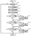
次に、本発明の建設機械の第1の実施の形態を構成するメインコントローラ100について図を用いて説明する。図3は本発明の建設機械の第1の実施の形態を構成するメインコントローラの構成を示す概念図、図4は本発明の建設機械の第1の実施の形態を構成するメインコントローラのメインスプール制御部の演算内容の一例を示す制御ブロック図、図5は本発明の建設機械の第1の実施の形態を構成するメインコントローラのブーム増速制御部の演算内容の一例を示す制御ブロック図である。
Next, the
図3に示すように、メインコントローラ100は、目標パイロット圧演算部110と、作業機位置取得部120と、目標面距離取得部130と、メインスプール制御部140と、ブーム増速制御部150とを備えている。
As shown in FIG. 3, the
目標パイロット圧演算部110は、右操作レバー装置1cからのブーム操作量信号と、左操作レバー装置1dからのアーム操作量信号とを入力し、入力信号に応じてブーム上げ目標パイロット圧と、ブーム下げ目標パイロット圧と、アームクラウド目標パイロット圧と、アームダンプ目標パイロット圧を演算して、メインスプール制御部140へ出力する。なお、ブーム操作量がブーム上げ方向に大きいほど、ブーム上げ目標パイロット圧を大きくし、ブーム操作量がブーム下げ方向に大きいほど、ブーム下げ目標パイロット圧を大きくする。同様に、アーム操作量がアームクラウド方向に大きいほど、アームクラウド目標パイロット圧を大きくし、アーム操作量がアームダンプ方向に大きいほど、アームダンプ目標パイロット圧を大きくする。
The target pilot
作業機位置取得部120は、角度検出器13a、13bからのブーム角度信号とアーム角度信号を入力し、入力信号に応じて予め設定されているブーム11とアーム12の幾何学情報を用いてバケット8の先端位置を演算して、作業機位置信号として目標面距離取得部130へ出力する。ここで、作業機位置は、例えば建設機械に固定された座標系の1点として演算される。ただし、作業機位置はこれに限らず、作業機15の形状を考慮した複数の点群として演算されてもよい。また、特許文献1に記載されている建設機械の軌跡制御装置と同様の演算を行ってもよい。
The work machine
目標面距離取得部130は、情報コントローラ200から送信される目標面情報と、作業機位置取得部120からの作業機位置信号とを入力し、作業機15と施工目標面との距離(以下、目標面距離という)を演算し、メインスプール制御部140、ブーム増速制御部150へ出力する。ここで目標面情報は、例えば建設機械に固定された2次元平面座標系の2点として与えられる。ただし、目標面情報はこれに限らず、グローバル3次元座標系に平面を構成する3点として与えられてもよいが、この場合は作業機位置と同じ座標系へ座標変換を行う必要がある。また、作業機位置が点群として演算された場合は、目標面情報に最も近い点を用いて目標面距離を演算してもよい。また、特許文献1に記載されている建設機械の軌跡制御装置の最短距離Δhと同様の演算を行ってもよい。
The target surface distance acquisition unit 130 inputs the target surface information transmitted from the
メインスプール制御部140は、モード設定スイッチ32から送信される半自動制御有効フラグと、目標パイロット圧演算部110からのブーム上げ目標パイロット圧と、ブーム下げ目標パイロット圧と、アームクラウド目標パイロット圧と、アームダンプ目標パイロット圧と、目標面距離取得部130からの目標面距離信号とを入力し、半自動制御有効フラグが真である場合には、目標面距離に応じて各目標パイロット圧を補正演算して、ブーム上げ電磁弁駆動信号、ブーム下げ電磁弁駆動信号、アームクラウド電磁弁駆動信号、アームダンプ電磁弁駆動信号を演算し、それぞれの信号に対応する電磁比例弁23a、23b、25a、25bを駆動する駆動信号を出力する。メインスプール制御部140で行う演算の詳細は後述する。
The main
ブーム増速制御部150は、モード設定スイッチ32から送信される半自動制御有効フラグと、メインスプール制御部140からのブーム上げ制御パイロット圧と、目標面距離取得部130からの目標面距離信号と、圧力センサ5b、6bから送信されるそれぞれブームシリンダボトム側油室の圧力信号(以下ブームボトム圧信号ともいう)、アームシリンダボトム側油室の圧力信号(以下アームボトム圧信号ともいう)を入力し、ブーム上げ目標パイロット圧を補正演算して、ブーム上げ増速電磁弁駆動信号を演算し、電磁比例弁24aを駆動する駆動信号を出力する。ブーム増速制御部150で行う演算の詳細は後述する。
The boom
メインスプール制御部140で行う演算の一例を、図4を用いて説明する。メインスプール制御部140は、ブーム上げ補正パイロット圧テーブル141と、最大値選択器142と、アームクラウド補正パイロット圧ゲインテーブル143と、乗算器144と、選択器145a、145cと、電磁弁駆動信号テーブル146a、146b、146c、146dとを備えている。
An example of calculation performed by the main
ブーム上げ補正パイロット圧テーブル141は、目標面距離信号を入力し、予め設定したテーブルを用いてブーム上げ補正パイロット圧を演算して、最大値選択器142へ出力する。最大値選択器142は、ブーム上げ目標パイロット圧とブーム上げ補正パイロット圧とを入力し、いずれかの最大値を選択して、選択器145aの第2入力端へ出力する。ブーム上げ補正パイロット圧テーブル141は、目標面距離が負の方向に大きくなるほど、すなわち作業機15が目標面に深く侵入するほど、ブーム上げ補正パイロット圧が大きくなるように設定する。これにより、目標面距離に応じてブーム上げ動作が行われ、作業機15の目標面への侵入を制限することができる。
The boom raising correction pilot pressure table 141 receives a target surface distance signal, calculates a boom raising correction pilot pressure using a preset table, and outputs it to the maximum value selector 142. The maximum value selector 142 receives the boom raising target pilot pressure and the boom raising correction pilot pressure, selects one of the maximum values, and outputs it to the second input terminal of the
選択器145aは、ブーム上げ目標パイロット圧信号を第1入力端に、上述した最大値選択器142の出力信号を第2入力端にそれぞれ入力すると共に、半自動制御有効フラグ信号を切換入力端に入力する。選択器145aは、半自動制御有効フラグ信号が偽の場合にブーム上げ目標パイロット圧信号を選択出力し、半自動制御有効フラグ信号が真の場合に、ブーム上げ目標パイロット圧信号とブーム上げ補正パイロット圧信号のいずれかの最大値を選択出力する。選択器145aからの出力信号は、ブーム上げ制御パイロット圧信号として、電磁弁駆動信号テーブル146aとブーム増速制御部150へ出力する。
The
電磁弁駆動信号テーブル146aは、入力するブーム上げ制御パイロット圧信号に応じて、予め設定したテーブルを用いて、電磁弁駆動信号を演算して出力し、電磁比例弁23aを駆動する。同様に電磁弁駆動信号テーブル146bは、入力するブーム上げ下げ目標パイロット圧信号に応じて、予め設定したテーブルを用いて、電磁弁駆動信号を演算して出力し、電磁比例弁23bを駆動する。 The electromagnetic valve drive signal table 146a calculates and outputs an electromagnetic valve drive signal using a preset table according to the input boom raising control pilot pressure signal, and drives the electromagnetic proportional valve 23a. Similarly, the electromagnetic valve drive signal table 146b calculates and outputs an electromagnetic valve drive signal using a preset table in accordance with the input boom up / down target pilot pressure signal, and drives the electromagnetic proportional valve 23b.
アームクラウド補正パイロット圧ゲインテーブル143は、目標面距離信号を入力し、目標面距離に応じて、予め設定したテーブルを用いて、アームクラウド補正パイロット圧ゲインを演算して、乗算器144へ出力する。乗算器144は、アームクラウド目標パイロット圧とアームクラウド補正パイロット圧ゲインとを入力し、入力値を乗算して、選択器145cの第2入力端へ出力する。アームクラウド補正パイロット圧ゲインテーブル143は、目標面距離が負の方向に大きくなるほど、すなわち作業機15が目標面に深く侵入するほど、アームクラウド補正パイロット圧ゲインが小さくなるように設定する。これにより、目標面距離に応じてアームクラウド速度が小さくなり、作業機15の目標面への侵入を制限することができる。
The arm cloud correction pilot pressure gain table 143 inputs a target surface distance signal, calculates an arm cloud correction pilot pressure gain using a table set in advance according to the target surface distance, and outputs the calculated value to the
選択器145cは、アームクラウド目標パイロット圧信号を第1入力端に、上述した乗算器144の出力信号を第2入力端にそれぞれ入力すると共に、半自動制御有効フラグ信号を切換入力端に入力する。選択器145cは、半自動制御有効フラグ信号が偽の場合にアームクラウド目標パイロット圧信号を選択出力し、半自動制御有効フラグ信号が真の場合に、アームクラウド目標パイロット圧信号とアームクラウド補正パイロット圧ゲインとを乗算したアームクラウド補正パイロット圧信号を選択出力する。選択器145cからの出力信号は、アームクラウド制御パイロット圧信号として、電磁弁駆動信号テーブル146cへ出力する。
The
電磁弁駆動信号テーブル146cは、入力するアームクラウド制御パイロット圧信号に応じて、予め設定したテーブルを用いて、電磁弁駆動信号を演算して出力し、電磁比例弁25aを駆動する。同様に電磁弁駆動信号テーブル146dは、入力するアームダンプ目標パイロット圧信号に応じて、予め設定したテーブルを用いて、電磁弁駆動信号を演算して出力し、電磁比例弁25bを駆動する。 The electromagnetic valve drive signal table 146c calculates and outputs an electromagnetic valve drive signal using a preset table in accordance with the input arm cloud control pilot pressure signal, and drives the electromagnetic proportional valve 25a. Similarly, the solenoid valve drive signal table 146d calculates and outputs a solenoid valve drive signal using a preset table in accordance with the input arm dump target pilot pressure signal, and drives the solenoid proportional valve 25b.
なお、特許文献1に記載されているベクトル方向補正によりブーム上げ目標パイロット圧、アームクラウド目標パイロット圧を補正しても良い。
In addition, you may correct | amend a boom raising target pilot pressure and an arm cloud target pilot pressure by the vector direction correction | amendment described in
次に、ブーム増速制御部150で行う演算の一例を、図5を用いて説明する。ブーム増速制御部150は、減算器151と、パイロット圧上限値テーブル152と、第2パイロット圧上限値テーブル153と、第3パイロット圧上限値テーブル154と、最大値選択器155と、最小値選択器156と、選択器157と、電磁弁駆動信号テーブル158とを備えている。
Next, an example of calculation performed by the boom
減算器151は、ブームボトム圧信号とアームボトム圧信号を入力し、ブームボトム圧信号からアームボトム圧信号を引いて圧力偏差を演算してパイロット圧上限値テーブル152に出力する。ここで、圧力偏差が小さくなることは、ブームボトム圧に対してアームボトム圧が増加することを示し、これは、作業機15にかかる掘削負荷が増加したことを示している。パイロット圧上限値テーブル152は入力した圧力偏差に応じて、予め設定したテーブルを用いて、パイロット圧上限値を演算して最大値選択器155へ出力する。
The
パイロット圧上限値テーブル152は、ブームボトム圧信号とアームボトム圧信号の圧力偏差が小さいほど、すなわち作業機15にかかる掘削負荷が大きいほど、パイロット圧上限値が小さくなるように設定する。こうすることにより、掘削負荷が増大した場合に、アームボトム圧が増加してブームボトム圧との偏差が小さくなったことを検出し、電磁比例弁24aが吐出するブーム上げ増速パイロット圧を制限してブーム増速方向制御弁24のメータイン開口を制限する。よって、第2油圧ポンプ22からブームシリンダ5への分流が抑制され、アームシリンダ6とブームシリンダ5の速度バランスが保たれるため、所定の仕上げ精度を得ることができる。
The pilot pressure upper limit value table 152 is set such that the pilot pressure upper limit value decreases as the pressure deviation between the boom bottom pressure signal and the arm bottom pressure signal decreases, that is, as the excavation load applied to the work implement 15 increases. By doing this, when the excavation load increases, it is detected that the arm bottom pressure has increased and the deviation from the boom bottom pressure has become small, and the boom raising acceleration pilot pressure discharged by the electromagnetic
第2パイロット圧上限値テーブル153は、入力したアームボトム圧信号に応じて、予め設定したテーブルを用いて、第2パイロット圧上限値を演算して最大値選択器155へ出力する。第2パイロット圧上限値テーブル153は、アームボトム圧信号が大きいほど、第2パイロット圧上限値が大きくなるように設定する。なお、図中に点線Aで示すアームボトム圧はリリーフ圧と略一致しており、アームボトム圧がリリーフ圧と略一致するまでに第2パイロット圧上限値を最大とする。こうすることにより、アームボトム圧が増加してリリーフ圧に近づいたことを検出し、電磁比例弁24aが吐出するブーム上げ増速パイロット圧を増加してブーム増速方向制御弁24のメータイン開口を大きくする。よって、第2油圧ポンプ22からブームシリンダ5への分流を可能とし、リリーフによる損失を回避できる。結果として、上述したアームボトム圧が増加してブームボトム圧との偏差が小さくなった場合であっても、アームシリンダ6とブームシリンダ5の速度バランスを保つべくブーム増速方向制御弁24のメータイン開口が制限された後、アームボトム圧が大きくなりすぎた場合にブーム増速方向制御弁24のメータイン開口を大きくすることにより、ブーム及びアームの速度バランスを保ったままリリーフによる圧損を回避することが可能となる。
The second pilot pressure upper limit value table 153 calculates the second pilot pressure upper limit value using a preset table according to the input arm bottom pressure signal, and outputs the second pilot pressure upper limit value to the
第3パイロット圧上限値テーブル154は、目標面距離信号を入力し、予め設定したテーブルを用いて、第3パイロット圧上限値を演算して最大値選択器155へ出力する。第3パイロット圧上限値テーブル154は、目標面距離が大きいほど、第2パイロット圧上限値が大きくなるように設定する。こうすることにより、作業機15が目標面から遠い位置では、第2油圧ポンプ22からブームシリンダ5への分流を確実に可能とし、リリーフによる損失を回避できる。
The third pilot pressure upper limit value table 154 receives the target surface distance signal, calculates a third pilot pressure upper limit value using a preset table, and outputs it to the
最大値選択器155は、パイロット圧上限値と第2パイロット圧上限値と第3パイロット圧上限値とを入力し、いずれかの最大値を選択して、パイロット圧上限値を補正して最小値選択器156へ出力する。
The
最小値選択器156は、オペレータのレバー操作により発生したブーム上げ制御パイロット圧と最大値選択器155からのパイロット圧上限値とを入力し、いずれかの最小値を選択することでブーム上げ制御パイロット圧を補正して選択器157の第2入力端へ出力する。
The
選択器157は、ブーム上げ制御パイロット圧信号を第1入力端に、上述した最小値選択器156の出力信号を第2入力端にそれぞれ入力すると共に、半自動制御有効フラグ信号を切換入力端に入力する。選択器157は、半自動制御有効フラグ信号が偽の場合にブーム上げ制御パイロット圧信号を選択出力し、半自動制御有効フラグ信号が真の場合に、ブーム上げ制御パイロット圧をブームボトム圧、アームボトム圧、目標面距離に応じて補正した値を選択して出力する。選択器157からの出力信号は、電磁弁駆動信号テーブル158へ出力する。
The
電磁弁駆動信号テーブル158はブーム上げ制御パイロット圧に応じて、予め設定したテーブルを用いて、ブーム上げ増速電磁弁駆動信号を演算して出力し、電磁比例弁24aを駆動する。
The solenoid valve drive signal table 158 calculates and outputs a boom lift acceleration solenoid valve drive signal using a preset table in accordance with the boom lift control pilot pressure, and drives the electromagnetic
次に、ブーム増速制御部150の演算フローについて図6を用いて説明する。図6は本発明の建設機械の第1の実施の形態を構成するメインコントローラのブーム増速制御部の演算のフローの一例を示すフローチャート図である。
メインコントローラ100のブーム増速制御部150は、半自動制御が有効か否かを判断する(ステップS101)。具体的には、半自動制御有効フラグ信号が真か偽かを判断する。半自動制御有効フラグ信号が真の場合(ステップS102)へ進み、それ以外の場合はリターンへ進む。
Next, the calculation flow of the boom
The boom
ブーム増速制御部150は、パイロット圧上限値と第2パイロット圧上限値と第3パイロット圧上限値とを演算する(ステップS102、S103、S104)。具体的には、上述したパイロット圧上限値テーブル152と第2パイロット圧上限値テーブル153と第3パイロット圧上限値テーブル154とで実行される。
The boom
ブーム増速制御部150は、パイロット圧上限値が第2パイロット圧上限値超過か否かを判断する(ステップS105)。パイロット圧上限値が第2パイロット圧上限値超過の場合(ステップS107)へ進み、それ以外の場合は(ステップS106)へ進む。
The boom
(ステップS105)にて、パイロット圧上限値が第2パイロット圧上限値超過でない場合、ブーム増速制御部150は、パイロット圧上限値を第2パイロット圧上限値に設定する(ステップS106)。その後、(ステップS107)へ進む。
When the pilot pressure upper limit value is not exceeding the second pilot pressure upper limit value in (Step S105), the boom
ブーム増速制御部150は、パイロット圧上限値が第3パイロット圧上限値超過か否かを判断する(ステップS107)。パイロット圧上限値が第3パイロット圧上限値超過の場合(ステップS109)へ進み、それ以外の場合は(ステップS108)へ進む。
The boom
(ステップS107)にて、パイロット圧上限値が第3パイロット圧上限値超過でない場合、ブーム増速制御部150は、パイロット圧上限値を第3パイロット圧上限値に設定する(ステップS108)。その後、(ステップS109)へ進む。
If the pilot pressure upper limit value does not exceed the third pilot pressure upper limit value in (Step S107), the boom
ブーム増速制御部150は、ブーム制御パイロット圧がパイロット圧上限値未満か否かを判断する(ステップS109)。ブーム制御パイロット圧がパイロット圧上限値未満の場合は、リターンに進み、ブーム上げ制御パイロット圧に応じてブーム上げ増速電磁弁24aを制御する。この場合には、本願発明の特徴である掘削負荷等によるブーム増速方向制御弁24の駆動量の制御は実行されない。ブーム制御パイロット圧がパイロット圧上限値未満でない場合は(ステップS110)へ進む。
The boom
(ステップS109)にて、ブーム制御パイロット圧がパイロット圧上限値未満でない場合、ブーム増速制御部150は、ブーム上げ制御パイロット圧をパイロット圧上限値に設定する(ステップS110)。具体的にはパイロット圧上限値に応じてブーム上げ増速電磁弁24aを制御する。この結果、掘削負荷等によるブーム増速方向制御弁24の駆動量の制御がなされるので、掘削負荷が増大してもリリーフによる損失を回避しつつ、分流を抑制して目標軌跡からの逸脱を防止できる。
If the boom control pilot pressure is not less than the pilot pressure upper limit value (step S109), the boom speed increasing
次に、本発明の建設機械の第1の実施の形態の動作について図を用いて説明する。図7Aは従来の建設機械の時系列の動作の一例を示す特性図、図7Bは本発明の建設機械の一実施の形態における建設機械の時系列の動作の一例を示す特性図である。 Next, operation | movement of 1st Embodiment of the construction machine of this invention is demonstrated using figures. FIG. 7A is a characteristic diagram showing an example of time-series operation of a conventional construction machine, and FIG. 7B is a characteristic diagram showing an example of time-series operation of the construction machine in one embodiment of the construction machine of the present invention.
図7Aは、ブーム方向制御弁23、ブーム増速方向制御弁24を同一のパイロット圧で駆動した場合の例を示し、図7Bはブーム方向制御弁23、ブーム増速方向制御弁24を個別のパイロット圧で駆動した場合の例を示す。
FIG. 7A shows an example in which the boom direction control valve 23 and the boom acceleration
図7Aおよび図7Bにおいて、横軸は時間を示していて、縦軸は、(a)目標面距離、(b)シリンダ速度、(c)メータイン開口面積、(d)アームボトム圧力とシリンダボトム圧力をそれぞれ示している。なお、目標面距離とは作業機15と施工目標面までの距離をいう。また、時刻T1は、ブームシリンダ5のブームボトム圧よりもアームシリンダ6のアームボトム圧の圧力が高くなった時刻を示している。
7A and 7B, the horizontal axis indicates time, and the vertical axis indicates (a) target surface distance, (b) cylinder speed, (c) meter-in opening area, (d) arm bottom pressure and cylinder bottom pressure. Respectively. The target surface distance refers to the distance between the
図7Aにおいて、時刻T0から掘削を開始すると、アームシリンダ6へ圧油が供給され(b)に示すようにアームシリンダ速度が増加する。目標面距離が0になると(c)に示すようにブーム方向制御弁23のメータイン開口面積が増加し、ブームシリンダ5へ圧油が供給されブームシリンダ速度が増加する。なお、ここでは図の簡略化のため、ブーム方向制御弁23とブーム増速方向制御弁24のパイロット圧に対する開口特性が同一であったと仮定して説明する。ブームシリンダ速度が増加することで、(a)に示すように作業機15が施工目標面に沿って動作し、目標面距離が0付近に保たれる。また、このとき、(d)に示すように掘削反力によってアームボトム圧が増加し、逆にブームボトム圧が減少する。
In FIG. 7A, when excavation is started from time T0, pressure oil is supplied to the
時刻T1において、ブームボトム圧よりもアームボトム圧が高くなるにつれ、ブーム増速方向制御弁24を通過する分流量が増加するので、(b)に示すようにブームシリンダ速度が増加してアームシリンダ速度が減少する。この結果、目標面距離が増加する。これは、換言すると、作業機15が施工目標面から浮き上がってしまうという問題を生起する。
At time T1, as the arm bottom pressure becomes higher than the boom bottom pressure, the amount of flow passing through the boom speed increasing
次に、本実施の形態における動作を図7Bを用いて説明する。図7Bにおいても、時刻T1’までは、図7Aの場合と同様に動作する。本実施の形態においては、時刻T1’から時刻T1において、アームボトム圧がブームボトム圧に近づくと、(c)に示すようにブーム増速方向制御弁24のメータイン開口面積が減少するので、ブーム増速方向制御弁24を通過する分流量が増加しない。このことにより、(b)に示すようにブームシリンダ速度とアームシリンダ速度のバランスが保たれる。
Next, the operation in this embodiment will be described with reference to FIG. 7B. 7B also operates in the same manner as in FIG. 7A until time T1 '. In the present embodiment, when the arm bottom pressure approaches the boom bottom pressure from time T1 ′ to time T1, the meter-in opening area of the boom speed increasing
これは、上述したようにブーム増速制御部150における制御により、アームボトム圧に応じてブーム増速方向制御弁24に作用するパイロット圧が制限されるためである。この結果、(a)に示すように目標面距離が0付近に保たれる。
This is because the pilot pressure acting on the boom acceleration
上述した本発明の建設機械の第1の実施の形態によれば、掘削負荷に応じて第2方向制御弁と分流可能に構成された第1増速方向制御弁の駆動量を制御するので、掘削負荷が増大してもリリーフによる損失を回避しつつ、分流を抑制して目標軌跡からの逸脱を防止できる。この結果、所定の仕上げ精度を確保できる。 According to the first embodiment of the construction machine of the present invention described above, since the drive amount of the first speed increasing direction control valve configured to be divertable with the second direction control valve is controlled according to the excavation load, Even if the excavation load increases, loss due to relief can be avoided and the diversion can be suppressed to prevent deviation from the target locus. As a result, a predetermined finishing accuracy can be ensured.
以下、本発明の建設機械の第2の実施の形態を図面を用いて説明する。図8Aは従来の建設機械におけるブーム方向制御弁、ブーム増速方向制御弁の開口特性の一例を示す開口特性図、図8Bは本発明の建設機械の第2の実施の形態を構成するブーム方向制御弁、ブーム増速方向制御弁の開口特性の一例を示す開口特性図である。 Hereinafter, a second embodiment of the construction machine of the present invention will be described with reference to the drawings. FIG. 8A is an opening characteristic diagram showing an example of an opening characteristic of a boom direction control valve and a boom speed increasing direction control valve in a conventional construction machine, and FIG. 8B is a boom direction constituting a second embodiment of the construction machine of the present invention. It is an opening characteristic figure which shows an example of the opening characteristic of a control valve and a boom acceleration direction control valve.
本発明の建設機械の第2の実施の形態において、油圧駆動装置の構成は、大略第1の実施の形態と同じであるが、パイロット圧に対する開口面積特性を一般的な従来技術の特性から変更した点が異なる。 In the second embodiment of the construction machine of the present invention, the configuration of the hydraulic drive device is substantially the same as that of the first embodiment, but the opening area characteristic with respect to the pilot pressure is changed from the characteristic of the general prior art. The difference was.
図8Aの(a)は従来の建設機械におけるブーム上げパイロット圧に対するブーム方向制御弁23のブーム上げ側の開口面積を示し、図8Aの(b)は従来の建設機械におけるブーム上げ増速パイロット圧に対するブーム増速方向制御弁24のブーム上げ側の開口面積を示している。同様に、図8Bの(a)は本発明の第2の実施の形態におけるブーム上げパイロット圧に対するブーム方向制御弁23のブーム上げ側の開口面積を示し、図8Bの(b)は本発明の第2の実施の形態におけるブーム上げ増速パイロット圧に対するブーム増速方向制御弁24のブーム上げ側の開口面積を示している。なお、各図において、実線はメータインの開口面積特性を示し、破線はメータアウトの開口面積特性を示している。
8A shows the opening area on the boom raising side of the boom direction control valve 23 with respect to the boom raising pilot pressure in the conventional construction machine, and FIG. 8A (b) shows the boom raising acceleration pilot pressure in the conventional construction machine. The opening area on the boom raising side of the boom speed increasing
従来技術では、図8Aに示すように、ブーム方向制御弁23、ブーム増速方向制御弁24において、それぞれのブーム上げパイロット圧に対してメータインの開口面積とメータアウトの開口面積が同時に開くように設定されているのが一般的である。
In the prior art, as shown in FIG. 8A, in the boom direction control valve 23 and the boom speed increasing
これに対して、本実施の形態においては、図8Bの(a)に示すように、ブーム方向制御弁23を、ブーム上げパイロット圧に対してメータインの開口面積が、メータアウトの開口面積よりも先に増加し始めるように設定し、ブーム増速方向制御弁24を図8Bの(b)に示すように、ブーム上げ増速パイロット圧に対してメータアウトの開口面積が、メータインの開口面積よりも先に増加し始めるように設定している。また、ブーム方向制御弁23のメータアウトの開口面積とブーム増速方向制御弁24のメータアウトの開口面積とを同じパイロット圧が作用したとして比較した場合、ブーム増速方向制御弁24のメータアウトの開口面積の方が、ブーム方向制御弁23のメータアウトの開口面積より先に増加し始めるように設定している。換言すると、ブーム増速方向制御弁24の開き始めのパイロット圧を、ブーム方向制御弁23の開き始めのパイロット圧より低い値に設定している。
On the other hand, in the present embodiment, as shown in FIG. 8B (a), the boom direction control valve 23 has a meter-in opening area larger than a meter-out opening area with respect to the boom raising pilot pressure. First, the boom acceleration
このように開口面積特性を設定することにより、パイロット圧が低い領域、すなわちブーム速度が低い領域では、ブームのメータアウトの開口面積をブーム増速方向制御弁24のみで調節することができる。
By setting the opening area characteristic in this manner, the opening area of the boom meter-out can be adjusted only by the boom speed increasing
例えば、本実施の形態においてブーム上げパイロット圧を図8Bの(a)に示す破線Pi1、ブーム上げ増速パイロット圧を図8Bの(b)に示す破線Pi2として与えた場合と、従来技術においてブーム上げパイロット圧を図8Aの(a)に示す破線Pi1、ブーム上げ増速パイロット圧を図8Aの(b)に示す破線Pi2として与えた場合とを比較すると、合計のメータアウト開口面積は、本実施の形態のほうが従来技術よりも小さくなる。 For example, in the present embodiment, the boom raising pilot pressure is given as the broken line Pi1 shown in FIG. 8B (a), and the boom raising acceleration pilot pressure is given as the broken line Pi2 shown in FIG. 8B (b). Compared with the case where the raised pilot pressure is given as the broken line Pi1 shown in FIG. 8A (a) and the boom raising acceleration pilot pressure is given as the broken line Pi2 shown in FIG. 8A (b), the total meter-out opening area is The embodiment is smaller than the prior art.
このため、本実施の形態においては、例えば掘削負荷が増大した場合に、ブーム上げ増速パイロット圧を制限すると、ブーム増速方向制御弁24のメータイン開口を閉じると同時にメータアウト開口面積を小さくすることができるので、ブームロッド圧を上昇させることができる。このことにより、掘削反力によるブームシリンダ5の伸長方向の負荷圧力低下を防止できるので、アームシリンダ6とブームシリンダ5の速度バランスが保たれる。この結果、所定の仕上げ精度を得ることができる。
For this reason, in this embodiment, for example, when the excavation load increases and the boom raising acceleration pilot pressure is limited, the meter-in opening area of the boom acceleration
次に、本発明の建設機械の第2の実施の形態の動作について図を用いて説明する。図9Aは本発明の建設機械の第2の実施の形態において、従来技術の開口面積特性を備えた方向制御弁を適用した建設機械の時系列の動作の一例を示す特性図、図9Bは本発明の建設機械の第2の実施の形態における建設機械の時系列の動作の一例を示す特性図である。 Next, operation | movement of 2nd Embodiment of the construction machine of this invention is demonstrated using figures. FIG. 9A is a characteristic diagram showing an example of time-series operation of a construction machine to which a directional control valve having an opening area characteristic of the prior art is applied in the second embodiment of the construction machine of the present invention, and FIG. It is a characteristic view which shows an example of the time series operation | movement of the construction machine in 2nd Embodiment of the construction machine of invention.
図9Aおよび図9Bにおいて、横軸は時間を示していて、縦軸は、(a)目標面距離、(b)シリンダ速度、(c)メータイン開口面積、(d)メータアウト開口面積、(e)アームボトム圧力とシリンダボトム圧力をそれぞれ示している。なお、目標面距離とは作業機15と施工目標面までの距離をいう。また、時刻T1は、ブームシリンダ5のブームボトム圧よりもアームシリンダ6のアームボトム圧の圧力が高くなった時刻を、時刻T2はブームシリンダ5のブームボトム圧が略0となった時刻を示している。
9A and 9B, the horizontal axis indicates time, and the vertical axis indicates (a) target surface distance, (b) cylinder speed, (c) meter-in opening area, (d) meter-out opening area, (e ) Arm bottom pressure and cylinder bottom pressure are shown respectively. The target surface distance refers to the distance between the
図9Aにおいて、時刻T0から掘削を開始すると、アームシリンダ6へ圧油が供給され(b)に示すようにアームシリンダ速度が増加する。目標面距離が0になると(c)に示すようにブーム方向制御弁23、ブーム増速方向制御弁24のメータイン開口が順次開き、ブームシリンダ5へ圧油が供給されブームシリンダ速度が増加する。同時に、(d)に示すようにブーム方向制御弁23、ブーム増速方向制御弁24のメータアウト開口も順次開き、これらの開口面積とブームシリンダ速度に応じたブームシリンダ5のロッド側の圧力(以下、ブームロッド圧と記載)が(e)に示すように発生する。ブームシリンダ速度が増加することで、(a)に示すように作業機15が施工目標面に沿って動作し、目標面距離が0付近に保たれる。また、このとき掘削反力によってアームボトム圧が増加し、逆にブームボトム圧が減少する。
In FIG. 9A, when excavation is started from time T0, pressure oil is supplied to the
時刻T1’から時刻T1において、アームボトム圧がブームボトム圧に近づくと、上述したようにブーム増速方向制御弁24に作用するパイロット圧が制限され、結果として(c)に示すようにブーム増速方向制御弁24のメータイン開口面積が減少するので、ブーム増速方向制御弁24を通過する分流量が増加せず、(b)に示すようにブームシリンダ速度とアームシリンダ速度のバランスが保たれる。このとき、(d)に示すようにブーム増速方向制御弁24のメータアウト開口面積も減少するが、ブーム方向制御弁23のメータアウト開口面積が相対的に大きいため、合計のメータアウト開口が比較的大きくなるので、(e)に示すブームロッド圧の増加量は小さい。
When the arm bottom pressure approaches the boom bottom pressure from the time T1 ′ to the time T1, the pilot pressure acting on the boom speed increasing
時刻T2において、(e)に示すように掘削反力によってブームボトム圧がさらに減少し、略0に達すると、(b)に示すようにブームシリンダ5が供給流量以上の速度で伸長し始める。この結果、(a)に示す目標面距離が増加する。これは、換言すると、作業機15が施工目標面から浮き上がってしまうという問題を生起する。
At time T2, as shown in (e), the boom bottom pressure is further reduced by the excavation reaction force, and when it reaches approximately 0, the boom cylinder 5 starts to extend at a speed equal to or higher than the supply flow rate as shown in (b). As a result, the target surface distance shown in (a) increases. In other words, this causes a problem that the
次に、本実施の形態における動作を図9Bを用いて説明する。図9Bにおいても、時刻T1’までは、図9Aの場合と同様に動作する。本実施の形態においては、時刻T1’から時刻T1においても、(c)に示すメータイン開口面積については図9Aと同様に動作する。一方、メータアウト開口面積については、(d)に示すように、ブーム増速方向制御弁24のメータアウト開口面積が大きく減少する。ブーム方向制御弁23のメータアウト開口面積よりもブーム増速方向制御弁24のメータアウト開口面積が相対的に大きく構成されているため、2弁の合計のメータアウト開口面積が比較的小さくなる。このことにより、(e)で示すように、ブームロッド圧が比較的大きく増加する。
Next, the operation in this embodiment will be described with reference to FIG. 9B. 9B also operates in the same manner as in FIG. 9A until time T1 '. In the present embodiment, from time T1 'to time T1, the meter-in opening area shown in (c) operates in the same manner as in FIG. 9A. On the other hand, as for the meter-out opening area, as shown in (d), the meter-out opening area of the boom speed increasing
時刻T2において、掘削反力によってブームボトム圧がさらに減少し、略0に達した場合であっても、(e)に示すようにブームロッド圧が比較的大きいため、(b)に示すようにブームシリンダ5が供給流量以上の速度で伸長することを防止できる。この結果、(a)に示すように目標面距離が0付近に保たれる。 Even at the time T2, the boom bottom pressure further decreases due to the excavation reaction force, and even when the boom bottom pressure reaches approximately 0, the boom rod pressure is relatively large as shown in (e). The boom cylinder 5 can be prevented from extending at a speed higher than the supply flow rate. As a result, the target surface distance is kept near 0 as shown in FIG.
上述した本発明の建設機械の第2の実施の形態によれば、第1の実施の形態と同様の効果を得ることができる。 According to the second embodiment of the construction machine of the present invention described above, the same effect as that of the first embodiment can be obtained.
なお、本発明は上記した実施形態に限定されるものではなく、様々な変形例が含まれる。例えば、上記した実施形態では、ブームシリンダ5及びアームシリンダ6を例に本発明を説明したが、これに限るものではない。
In addition, this invention is not limited to above-described embodiment, Various modifications are included. For example, in the above-described embodiment, the present invention has been described by taking the boom cylinder 5 and the
さらに、上記した実施形態は本発明を分かり易く説明するために詳細に説明したものであり、必ずしも説明した全ての構成を備えるものに限定されるものではない。 Further, the above-described embodiment has been described in detail for easy understanding of the present invention, and is not necessarily limited to the one having all the configurations described.
5:ブームシリンダ(第1油圧アクチュエータ)、6:アームシリンダ(第2油圧アクチュエータ)、5b:ブームシリンダボトム室側圧力センサ、6b:アームシリンダボトム室側圧力センサ(掘削負荷センサ)、15:作業機、21:第1油圧ポンプ、22:第2油圧ポンプ、23:ブーム方向制御弁(第1方向制御弁)、24:ブーム増速方向制御弁(第1増速方向制御弁)、25:アーム方向制御弁(第2方向制御弁)、32:モード設定スイッチ、100:メインコントローラ、130:目標面距離取得部、150:ブーム増速制御部、200:情報コントローラ、L1:第1ポンプライン、L2:第2ポンプライン 5: Boom cylinder (first hydraulic actuator), 6: Arm cylinder (second hydraulic actuator), 5b: Boom cylinder bottom chamber side pressure sensor, 6b: Arm cylinder bottom chamber side pressure sensor (excavation load sensor), 15: Work 21: first hydraulic pump, 22: second hydraulic pump, 23: boom direction control valve (first direction control valve), 24: boom acceleration direction control valve (first acceleration direction control valve), 25: Arm direction control valve (second direction control valve), 32: Mode setting switch, 100: Main controller, 130: Target surface distance acquisition unit, 150: Boom acceleration control unit, 200: Information controller, L1: First pump line , L2: Second pump line
Claims (5)
前記作業機にかかる掘削負荷を検出する掘削負荷センサと、
前記第1増速方向制御弁を駆動する第1増速制御部とを備え、
前記第1増速制御部は、前記掘削負荷センサで検出した掘削負荷に応じて前記第1増速方向制御弁の駆動量を制御する
ことを特徴とする建設機械。 A first hydraulic actuator, a second hydraulic actuator, a work machine driven by the first hydraulic actuator and the second hydraulic actuator, a first hydraulic pump, a second hydraulic pump, and a discharge oil path of the first hydraulic pump. A first directional control valve which is provided in a certain first pump line and controls the flow rate and direction of pressure oil supplied to the first hydraulic actuator; and a second pump line which is a discharge oil passage of the second hydraulic pump. A first speed-increasing direction control valve that controls the flow rate and direction of pressure oil supplied to the first hydraulic actuator, and a second pump line that is a discharge oil passage of the second hydraulic pump, In a construction machine comprising a second direction control valve for controlling a flow rate and direction of pressure oil supplied to a second hydraulic actuator,
An excavation load sensor for detecting an excavation load applied to the working machine;
A first speed increase control unit for driving the first speed increase direction control valve,
The construction machine characterized in that the first acceleration control unit controls a drive amount of the first acceleration direction control valve in accordance with an excavation load detected by the excavation load sensor.
前記作業機がブーム及びアームを備え、
前記第1油圧アクチュエータは前記ブームを駆動するブームシリンダであり、
前記第2油圧アクチュエータは前記アームを駆動するアームシリンダであり、
前記掘削負荷センサは前記アームシリンダのボトム側油室の圧力を計測するアームシリンダボトム室側圧力センサと、前記ブームシリンダのボトム側油室の圧力を計測するブームシリンダボトム室側圧力センサであり、
前記第1増速制御部は、前記ブームシリンダボトム室側圧力センサで計測したブームシリンダのボトム側油室の圧力と、前記アームシリンダボトム室側圧力センサで計測したアームシリンダのボトム側油室の圧力との偏差に基づいて前記第1増速方向制御弁の駆動量を制御する
ことを特徴とする建設機械。 The construction machine according to claim 1,
The working machine includes a boom and an arm;
The first hydraulic actuator is a boom cylinder for driving the boom;
The second hydraulic actuator is an arm cylinder that drives the arm;
The excavation load sensor is an arm cylinder bottom chamber pressure sensor that measures the pressure of the bottom oil chamber of the arm cylinder, and a boom cylinder bottom chamber pressure sensor that measures the pressure of the bottom oil chamber of the boom cylinder,
The first acceleration control unit includes a pressure of a bottom oil chamber of the boom cylinder measured by the boom cylinder bottom chamber pressure sensor, and a bottom oil chamber of the arm cylinder measured by the arm cylinder bottom chamber pressure sensor. A construction machine that controls a driving amount of the first speed increasing direction control valve based on a deviation from a pressure.
前記第1増速制御部は、前記ブームシリンダのボトム側油室の圧力と前記アームシリンダのボトム側油室の圧力との偏差が小さいほど前記第1増速方向制御弁の開口面積を小さくするよう制御し、前記アームシリンダのボトム側油室の圧力が大きくなるほど前記第1増速方向制御弁の開口面積を大きくするよう制御する
ことを特徴とする建設機械。 The construction machine according to claim 2,
The first acceleration control unit reduces the opening area of the first acceleration direction control valve as the deviation between the pressure in the bottom oil chamber of the boom cylinder and the pressure in the bottom oil chamber of the arm cylinder is smaller. The construction machine is characterized in that the opening area of the first speed increasing direction control valve is increased as the pressure in the bottom side oil chamber of the arm cylinder increases.
前記作業機が作業する目標面と前記作業機との距離である目標面距離を計測または演算する目標面距離取得部を更に備え、
前記第1増速制御部は、前記目標面距離に応じて、前記第1増速方向制御弁の駆動量を補正制御する
ことを特徴とする建設機械。 The construction machine according to claim 1,
A target surface distance acquisition unit that measures or calculates a target surface distance that is a distance between the target surface on which the work machine works and the work machine;
The construction machine according to claim 1, wherein the first acceleration control unit corrects and controls a drive amount of the first acceleration direction control valve according to the target surface distance.
前記第1方向制御弁及び前記第1増速方向制御弁は、パイロット油圧源より発生するパイロット圧油により駆動されると共に、
前記第1油圧アクチュエータの排出側油室と油圧タンクとを連通するメータアウト開口をそれぞれ備え、
前記第1方向制御弁のメータアウト開口が開き始めるパイロット圧の値よりも、前記第1増速方向制御弁のメータアウト開口が開き始める前記パイロット圧の値が低い値に設定された
ことを特徴とする建設機械。 The construction machine according to claim 1,
The first direction control valve and the first speed increasing direction control valve are driven by pilot pressure oil generated from a pilot hydraulic source,
A meter-out opening for communicating the discharge side oil chamber and the hydraulic tank of the first hydraulic actuator,
Said than the value of the meter-out opening opens started Rupa pilots pressure of the first directional control valve, the value of the meter-out opening begins to open the pilot pressure of the first speed increasing directional control valve is set to a low value Construction machine characterized by.
Priority Applications (6)
| Application Number | Priority Date | Filing Date | Title |
|---|---|---|---|
| JP2016070130A JP6495857B2 (en) | 2016-03-31 | 2016-03-31 | Construction machinery |
| CN201680070727.4A CN108368861B (en) | 2016-03-31 | 2016-11-17 | construction machinery |
| PCT/JP2016/084103 WO2017168822A1 (en) | 2016-03-31 | 2016-11-17 | Construction machinery |
| KR1020187014982A KR102110887B1 (en) | 2016-03-31 | 2016-11-17 | Construction machinery |
| US16/074,132 US10633825B2 (en) | 2016-03-31 | 2016-11-17 | Construction machine |
| EP16897038.2A EP3438468B1 (en) | 2016-03-31 | 2016-11-17 | Construction machine with speed-up control section |
Applications Claiming Priority (1)
| Application Number | Priority Date | Filing Date | Title |
|---|---|---|---|
| JP2016070130A JP6495857B2 (en) | 2016-03-31 | 2016-03-31 | Construction machinery |
Publications (3)
| Publication Number | Publication Date |
|---|---|
| JP2017180712A JP2017180712A (en) | 2017-10-05 |
| JP2017180712A5 JP2017180712A5 (en) | 2018-04-26 |
| JP6495857B2 true JP6495857B2 (en) | 2019-04-03 |
Family
ID=59962878
Family Applications (1)
| Application Number | Title | Priority Date | Filing Date |
|---|---|---|---|
| JP2016070130A Active JP6495857B2 (en) | 2016-03-31 | 2016-03-31 | Construction machinery |
Country Status (6)
| Country | Link |
|---|---|
| US (1) | US10633825B2 (en) |
| EP (1) | EP3438468B1 (en) |
| JP (1) | JP6495857B2 (en) |
| KR (1) | KR102110887B1 (en) |
| CN (1) | CN108368861B (en) |
| WO (1) | WO2017168822A1 (en) |
Families Citing this family (23)
| Publication number | Priority date | Publication date | Assignee | Title |
|---|---|---|---|---|
| JP6633464B2 (en) * | 2016-07-06 | 2020-01-22 | 日立建機株式会社 | Work machine |
| JP6707064B2 (en) * | 2017-08-24 | 2020-06-10 | 日立建機株式会社 | Hydraulic work machine |
| JP6966312B2 (en) | 2017-12-14 | 2021-11-10 | 日立建機株式会社 | Work machine |
| US11105066B2 (en) * | 2018-03-15 | 2021-08-31 | Hitachi Construction Machinery Co., Ltd. | Work machine |
| CN109083223B (en) * | 2018-07-27 | 2023-11-21 | 山东临工工程机械有限公司 | Hydraulic system of remote control loader |
| JP7141894B2 (en) * | 2018-09-05 | 2022-09-26 | 日立建機株式会社 | working machine |
| JP7149140B2 (en) * | 2018-09-18 | 2022-10-06 | 川崎重工業株式会社 | Multi-control valve unit and hydraulic drive for hydraulic excavators |
| JP7283910B2 (en) * | 2019-02-01 | 2023-05-30 | 株式会社小松製作所 | CONSTRUCTION MACHINE CONTROL SYSTEM, CONSTRUCTION MACHINE, AND CONSTRUCTION MACHINE CONTROL METHOD |
| JP7268435B2 (en) * | 2019-03-22 | 2023-05-08 | コベルコ建機株式会社 | Working machine hydraulic drive |
| JP7370724B2 (en) * | 2019-04-05 | 2023-10-30 | 株式会社竹内製作所 | Operation control device for work vehicles |
| JP7253478B2 (en) * | 2019-09-25 | 2023-04-06 | 日立建機株式会社 | working machine |
| KR20220067535A (en) | 2019-09-26 | 2022-05-24 | 스미토모 겐키 가부시키가이샤 | Shovel and shovel display device |
| JP2021095775A (en) * | 2019-12-18 | 2021-06-24 | 株式会社神戸製鋼所 | Work auxiliary device of work machine, and construction surface recognition method in work site |
| GB2593488B (en) * | 2020-03-24 | 2024-05-22 | Bamford Excavators Ltd | Hydraulic system |
| FI131037B1 (en) | 2020-06-03 | 2024-08-08 | Ponsse Oyj | Control of a boom system in a work machine |
| CN111764459A (en) * | 2020-07-10 | 2020-10-13 | 三一重机有限公司 | Start-up control method of hydraulic pump of excavator |
| CN112482485A (en) * | 2020-11-10 | 2021-03-12 | 徐州徐工挖掘机械有限公司 | Actuator trajectory control method, actuator trajectory control device, actuator trajectory control controller and storage medium |
| JP7444032B2 (en) | 2020-11-16 | 2024-03-06 | コベルコ建機株式会社 | construction machinery |
| JP7688503B2 (en) | 2021-03-30 | 2025-06-04 | 株式会社小松製作所 | Hydraulic system of hydraulic excavator, hydraulic excavator, and method for controlling hydraulic excavator |
| CN113153844B (en) * | 2021-05-31 | 2023-07-25 | 上海三一重机股份有限公司 | Hydraulic system, control method thereof, and work machine |
| JP7705331B2 (en) * | 2021-09-30 | 2025-07-09 | キャタピラー エス エー アール エル | Hydraulic control system for work machines |
| WO2023191014A1 (en) * | 2022-03-31 | 2023-10-05 | 日立建機株式会社 | Work machine |
| US12589768B2 (en) * | 2024-02-28 | 2026-03-31 | Aptiv Technologies AG | Path determination for autonomous vehicle parking |
Family Cites Families (21)
| Publication number | Priority date | Publication date | Assignee | Title |
|---|---|---|---|---|
| DE2656032B2 (en) * | 1976-12-10 | 1979-09-13 | Danfoss A/S, Nordborg (Daenemark) | Hydraulic system with at least two consumers |
| JP3767914B2 (en) | 1993-12-27 | 2006-04-19 | 日立建機株式会社 | Control equipment for hydraulic construction machinery |
| JP3059378B2 (en) * | 1996-04-17 | 2000-07-04 | 住友建機株式会社 | Hydraulic excavator control circuit |
| JP3571142B2 (en) | 1996-04-26 | 2004-09-29 | 日立建機株式会社 | Trajectory control device for construction machinery |
| JP3165048B2 (en) * | 1996-12-19 | 2001-05-14 | 住友建機株式会社 | Hydraulic excavator control circuit |
| JPH11131532A (en) * | 1997-10-28 | 1999-05-18 | Shin Caterpillar Mitsubishi Ltd | Control circuit for construction machine |
| JP4209705B2 (en) * | 2003-03-17 | 2009-01-14 | 日立建機株式会社 | Working machine hydraulic circuit |
| JP4410512B2 (en) * | 2003-08-08 | 2010-02-03 | 日立建機株式会社 | Hydraulic drive |
| KR100601458B1 (en) * | 2004-12-16 | 2006-07-18 | 두산인프라코어 주식회사 | Hydraulic control device for boom-arm combined motion of excavator |
| JP2007024103A (en) * | 2005-07-13 | 2007-02-01 | Hitachi Constr Mach Co Ltd | Hydraulic drive mechanism |
| JP2007100779A (en) * | 2005-10-03 | 2007-04-19 | Kayaba Ind Co Ltd | Hydraulic control device |
| JP5275187B2 (en) | 2009-09-17 | 2013-08-28 | 住友建機株式会社 | Hydraulic circuit for construction machinery |
| KR101652112B1 (en) * | 2009-12-23 | 2016-08-29 | 두산인프라코어 주식회사 | Hybrid Excavator Boom Actuator System and its Control Method |
| JP5647052B2 (en) * | 2011-03-25 | 2014-12-24 | 日立建機株式会社 | Hybrid construction machine |
| JP5356477B2 (en) | 2011-09-06 | 2013-12-04 | 住友建機株式会社 | Construction machinery |
| JP5938356B2 (en) | 2013-02-22 | 2016-06-22 | 日立建機株式会社 | Hydraulic drive device for hydraulic excavator |
| CN203614479U (en) * | 2013-11-08 | 2014-05-28 | 宣化钢铁集团有限责任公司 | Tundish lifting hydraulic device with high synchronization accuracy |
| EP3118465B1 (en) * | 2014-03-11 | 2021-01-20 | Sumitomo Heavy Industries, Ltd. | Shovel |
| US20170121930A1 (en) | 2014-06-02 | 2017-05-04 | Komatsu Ltd. | Construction machine control system, construction machine, and method of controlling construction machine |
| CN204729370U (en) * | 2015-07-02 | 2015-10-28 | 四川海洋特种技术研究所 | A kind of underwater hydraulic system shallow water testing apparatus hydraulic power unit |
| KR101737389B1 (en) * | 2015-09-25 | 2017-05-18 | 가부시키가이샤 고마쓰 세이사쿠쇼 | Work machine control device, work machine, and work machine control method |
-
2016
- 2016-03-31 JP JP2016070130A patent/JP6495857B2/en active Active
- 2016-11-17 KR KR1020187014982A patent/KR102110887B1/en active Active
- 2016-11-17 EP EP16897038.2A patent/EP3438468B1/en active Active
- 2016-11-17 US US16/074,132 patent/US10633825B2/en active Active
- 2016-11-17 WO PCT/JP2016/084103 patent/WO2017168822A1/en not_active Ceased
- 2016-11-17 CN CN201680070727.4A patent/CN108368861B/en active Active
Also Published As
| Publication number | Publication date |
|---|---|
| KR102110887B1 (en) | 2020-05-14 |
| EP3438468A4 (en) | 2020-05-20 |
| US10633825B2 (en) | 2020-04-28 |
| EP3438468A1 (en) | 2019-02-06 |
| CN108368861A (en) | 2018-08-03 |
| JP2017180712A (en) | 2017-10-05 |
| EP3438468B1 (en) | 2022-01-26 |
| KR20180075624A (en) | 2018-07-04 |
| WO2017168822A1 (en) | 2017-10-05 |
| US20190338494A1 (en) | 2019-11-07 |
| CN108368861B (en) | 2019-10-18 |
Similar Documents
| Publication | Publication Date | Title |
|---|---|---|
| JP6495857B2 (en) | Construction machinery | |
| CN110392755B (en) | Hydraulic work machine | |
| KR102255674B1 (en) | Working machine | |
| CN108368689B (en) | Control device for hydraulic construction machine | |
| US11286644B2 (en) | Hydraulic actuator for excavation work machine | |
| US10227997B2 (en) | Hydraulic drive system for work machine | |
| KR102091504B1 (en) | Construction machinery | |
| US10584722B2 (en) | Hydraulic fluid energy regeneration apparatus of work machine | |
| US10767674B2 (en) | Construction machine | |
| JP2018172860A (en) | Hydraulic control device for construction machine | |
| CN112424483B (en) | Construction machine | |
| US20210230843A1 (en) | Work machine | |
| KR102228436B1 (en) | Construction machinery | |
| US10662618B2 (en) | Construction machine | |
| JP2013249900A (en) | Hydraulic drive circuit | |
| WO2019180798A1 (en) | Construction machine |
Legal Events
| Date | Code | Title | Description |
|---|---|---|---|
| A521 | Written amendment |
Free format text: JAPANESE INTERMEDIATE CODE: A523 Effective date: 20180313 |
|
| A621 | Written request for application examination |
Free format text: JAPANESE INTERMEDIATE CODE: A621 Effective date: 20180313 |
|
| TRDD | Decision of grant or rejection written | ||
| A01 | Written decision to grant a patent or to grant a registration (utility model) |
Free format text: JAPANESE INTERMEDIATE CODE: A01 Effective date: 20190219 |
|
| A61 | First payment of annual fees (during grant procedure) |
Free format text: JAPANESE INTERMEDIATE CODE: A61 Effective date: 20190307 |
|
| R150 | Certificate of patent or registration of utility model |
Ref document number: 6495857 Country of ref document: JP Free format text: JAPANESE INTERMEDIATE CODE: R150 |