JP6492059B2 - Fluid path set bolus control device - Google Patents
Fluid path set bolus control device Download PDFInfo
- Publication number
- JP6492059B2 JP6492059B2 JP2016511804A JP2016511804A JP6492059B2 JP 6492059 B2 JP6492059 B2 JP 6492059B2 JP 2016511804 A JP2016511804 A JP 2016511804A JP 2016511804 A JP2016511804 A JP 2016511804A JP 6492059 B2 JP6492059 B2 JP 6492059B2
- Authority
- JP
- Japan
- Prior art keywords
- fluid
- connector
- check valve
- compressible
- control device
- Prior art date
- Legal status (The legal status is an assumption and is not a legal conclusion. Google has not performed a legal analysis and makes no representation as to the accuracy of the status listed.)
- Active
Links
Images




Classifications
-
- A—HUMAN NECESSITIES
- A61—MEDICAL OR VETERINARY SCIENCE; HYGIENE
- A61M—DEVICES FOR INTRODUCING MEDIA INTO, OR ONTO, THE BODY; DEVICES FOR TRANSDUCING BODY MEDIA OR FOR TAKING MEDIA FROM THE BODY; DEVICES FOR PRODUCING OR ENDING SLEEP OR STUPOR
- A61M39/00—Tubes, tube connectors, tube couplings, valves, access sites or the like, specially adapted for medical use
- A61M39/22—Valves or arrangement of valves
- A61M39/24—Check- or non-return valves
-
- A—HUMAN NECESSITIES
- A61—MEDICAL OR VETERINARY SCIENCE; HYGIENE
- A61M—DEVICES FOR INTRODUCING MEDIA INTO, OR ONTO, THE BODY; DEVICES FOR TRANSDUCING BODY MEDIA OR FOR TAKING MEDIA FROM THE BODY; DEVICES FOR PRODUCING OR ENDING SLEEP OR STUPOR
- A61M5/00—Devices for bringing media into the body in a subcutaneous, intra-vascular or intramuscular way; Accessories therefor, e.g. filling or cleaning devices, arm-rests
- A61M5/14—Infusion devices, e.g. infusing by gravity; Blood infusion; Accessories therefor
- A61M5/168—Means for controlling media flow to the body or for metering media to the body, e.g. drip meters, counters ; Monitoring media flow to the body
- A61M5/16804—Flow controllers
- A61M5/16827—Flow controllers controlling delivery of multiple fluids, e.g. sequencing, mixing or via separate flow-paths
-
- A—HUMAN NECESSITIES
- A61—MEDICAL OR VETERINARY SCIENCE; HYGIENE
- A61M—DEVICES FOR INTRODUCING MEDIA INTO, OR ONTO, THE BODY; DEVICES FOR TRANSDUCING BODY MEDIA OR FOR TAKING MEDIA FROM THE BODY; DEVICES FOR PRODUCING OR ENDING SLEEP OR STUPOR
- A61M39/00—Tubes, tube connectors, tube couplings, valves, access sites or the like, specially adapted for medical use
- A61M39/10—Tube connectors; Tube couplings
- A61M2039/1077—Adapters, e.g. couplings adapting a connector to one or several other connectors
-
- A—HUMAN NECESSITIES
- A61—MEDICAL OR VETERINARY SCIENCE; HYGIENE
- A61M—DEVICES FOR INTRODUCING MEDIA INTO, OR ONTO, THE BODY; DEVICES FOR TRANSDUCING BODY MEDIA OR FOR TAKING MEDIA FROM THE BODY; DEVICES FOR PRODUCING OR ENDING SLEEP OR STUPOR
- A61M39/00—Tubes, tube connectors, tube couplings, valves, access sites or the like, specially adapted for medical use
- A61M39/22—Valves or arrangement of valves
- A61M2039/226—Spindles or actuating means
-
- A—HUMAN NECESSITIES
- A61—MEDICAL OR VETERINARY SCIENCE; HYGIENE
- A61M—DEVICES FOR INTRODUCING MEDIA INTO, OR ONTO, THE BODY; DEVICES FOR TRANSDUCING BODY MEDIA OR FOR TAKING MEDIA FROM THE BODY; DEVICES FOR PRODUCING OR ENDING SLEEP OR STUPOR
- A61M39/00—Tubes, tube connectors, tube couplings, valves, access sites or the like, specially adapted for medical use
- A61M39/22—Valves or arrangement of valves
- A61M39/24—Check- or non-return valves
- A61M2039/242—Check- or non-return valves designed to open when a predetermined pressure or flow rate has been reached, e.g. check valve actuated by fluid
-
- A—HUMAN NECESSITIES
- A61—MEDICAL OR VETERINARY SCIENCE; HYGIENE
- A61M—DEVICES FOR INTRODUCING MEDIA INTO, OR ONTO, THE BODY; DEVICES FOR TRANSDUCING BODY MEDIA OR FOR TAKING MEDIA FROM THE BODY; DEVICES FOR PRODUCING OR ENDING SLEEP OR STUPOR
- A61M39/00—Tubes, tube connectors, tube couplings, valves, access sites or the like, specially adapted for medical use
- A61M39/22—Valves or arrangement of valves
- A61M39/24—Check- or non-return valves
- A61M2039/2433—Valve comprising a resilient or deformable element, e.g. flap valve, deformable disc
- A61M2039/2446—Flexible disc
- A61M2039/2466—Flexible disc being fixed in its center
-
- A—HUMAN NECESSITIES
- A61—MEDICAL OR VETERINARY SCIENCE; HYGIENE
- A61M—DEVICES FOR INTRODUCING MEDIA INTO, OR ONTO, THE BODY; DEVICES FOR TRANSDUCING BODY MEDIA OR FOR TAKING MEDIA FROM THE BODY; DEVICES FOR PRODUCING OR ENDING SLEEP OR STUPOR
- A61M5/00—Devices for bringing media into the body in a subcutaneous, intra-vascular or intramuscular way; Accessories therefor, e.g. filling or cleaning devices, arm-rests
- A61M5/14—Infusion devices, e.g. infusing by gravity; Blood infusion; Accessories therefor
- A61M5/142—Pressure infusion, e.g. using pumps
- A61M5/14212—Pumping with an aspiration and an expulsion action
- A61M5/14216—Reciprocating piston type
Landscapes
- Health & Medical Sciences (AREA)
- Heart & Thoracic Surgery (AREA)
- Hematology (AREA)
- Engineering & Computer Science (AREA)
- Anesthesiology (AREA)
- Biomedical Technology (AREA)
- Life Sciences & Earth Sciences (AREA)
- Animal Behavior & Ethology (AREA)
- General Health & Medical Sciences (AREA)
- Public Health (AREA)
- Veterinary Medicine (AREA)
- Pulmonology (AREA)
- Vascular Medicine (AREA)
- Infusion, Injection, And Reservoir Apparatuses (AREA)
Description
関連出願の相互参照
本出願は、2013年5月1日に出願された、名称を「Fluid Path Set Bolus Control Device」とする米国仮特許出願第61/818,056号明細書の優先権を主張し、その開示は参照により本出願に完全に組み込まれる。
CROSS REFERENCE TO RELATED APPLICATIONS This application claims priority from US Provisional Patent Application No. 61 / 818,056, filed May 1, 2013, with the name “Fluid Path Set Bolus Control Device”. The disclosure of which is fully incorporated herein by reference.
本開示は、医療用流体の送達用途、特に流体経路セットボーラス制御装置に関するものである。 The present disclosure relates to medical fluid delivery applications, and more particularly to fluid path set bolus control devices.
多数の医療診断および治療手段において、内科医などの医師は患者に医療用流体を注入する。近年、造影剤(contrast solution)(多くの場合、単に「造影剤(contrast)」と呼ばれる)などの流体を加圧注入するための多数のインジェクタ作動型の注射器および電動式注入器が、血管造影法、コンピュータ断層撮影法(CT)、超音波、およびNMR/MRIといった処置での使用のために開発されてきた。一般的に、これらの電動式注入器は、あらかじめ設定された流動速度で、あらかじめ設定された量の造影剤を送達するよう設計されている。 In many medical diagnostic and therapeutic measures, a physician, such as a physician, infuses a patient with medical fluid. In recent years, a number of injector-actuated syringes and motorized injectors for pressurizing fluids such as contrast solutions (often referred to simply as “contrasts”) have become angiographic. Have been developed for use in procedures such as CT, computed tomography (CT), ultrasound, and NMR / MRI. Generally, these motorized injectors are designed to deliver a preset amount of contrast agent at a preset flow rate.
典型的な血管造影検査において、医師は心臓カテーテルを静脈または動脈に配置する。カテーテルは手動または自動の造影剤注入メカニズムに連結される。典型的な手動の造影剤注入メカニズムには、カテーテル連結部と流体連結している注射器を含む。流体経路はまた、たとえば造影剤の源泉、フラッシング流体(通常は生理食塩水)の源泉、および患者の血圧を計測するための圧力トランスデューサを含んでもよい。典型的なシステムにおいて、造影剤の源泉は、弁、たとえば三方活栓を介して流体経路に連結されている。生理食塩水の源泉および圧力トランスデューサも、活栓などの追加の弁を介して流体経路に連結されてもよい。手動の造影剤注入メカニズムの操作者は注射器および各弁を制御して、生理食塩水または造影剤を注射器に引き入れ、カテーテル連結部から造影剤または生理食塩水を患者に注入する。 In a typical angiographic examination, a physician places a cardiac catheter in a vein or artery. The catheter is coupled to a manual or automatic contrast agent injection mechanism. A typical manual contrast injection mechanism includes a syringe in fluid communication with a catheter connection. The fluid path may also include, for example, a source of contrast agent, a source of flushing fluid (usually saline), and a pressure transducer for measuring patient blood pressure. In a typical system, the source of contrast agent is connected to the fluid pathway via a valve, such as a three-way stopcock. Saline sources and pressure transducers may also be coupled to the fluid pathway via additional valves such as stopcocks. The operator of the manual contrast injection mechanism controls the syringe and valves to draw saline or contrast into the syringe and inject contrast or saline into the patient from the catheter connection.
自動の造影剤注入メカニズムは通常、たとえば電動式線形アクチュエータを有する1つまたは複数の電動式注入器に連結された注射器を含む。通常、操作者は、一定の量の造影剤および/または生理食塩水、およびそれぞれの一定の注入速度に関して、電動式注入器の電子制御システムに設定を入力する。自動の造影剤注入メカニズムは、このような手動装置をうまく使用することが装置を操作する医師のスキルに左右される手動器具よりも、すぐれた制御を提供する。手動システムのように、自動の造影剤注入メカニズムから患者への流体経路は、たとえば造影剤の源泉、フラッシング流体(通常は生理食塩水)の源泉、および患者の血圧を計測するための圧力トランスデューサを含む。造影剤の源泉は、弁、たとえば三方活栓を介して流体経路に連結されている。生理食塩水の源泉および圧力トランスデューサも、活栓などの追加の弁を介して流体経路に連結されてもよい。 Automatic contrast agent injection mechanisms typically include a syringe coupled to one or more motorized injectors having, for example, a motorized linear actuator. Typically, the operator enters settings into the electronic control system of the motorized injector for a certain amount of contrast agent and / or saline and their respective constant infusion rates. An automatic contrast agent injection mechanism provides better control than manual instruments where the successful use of such manual devices depends on the skill of the physician operating the device. Like manual systems, the fluid path from the automatic contrast agent injection mechanism to the patient includes, for example, a source of contrast agent, a source of flushing fluid (usually saline), and a pressure transducer for measuring the patient's blood pressure. Including. The source of contrast agent is connected to the fluid pathway via a valve, such as a three-way stopcock. Saline sources and pressure transducers may also be coupled to the fluid pathway via additional valves such as stopcocks.
注入された造影剤は、患者の体、たとえば患者の鼠径部に挿入されたカテーテルによって、患者の体の所望の部位に送達される。造影剤の投与量は、ボーラスと呼ばれる。造影剤のボーラスが所望の部位に送達されると、その領域は、血管造影撮像またはスキャンなどの従来の撮像技術を用いて画像化される。造影剤は、周辺組織の背景に対して明確に視認可能となる。 The injected contrast agent is delivered to the desired site on the patient's body, for example, by a catheter inserted into the patient's groin. The dose of contrast agent is called a bolus. Once the contrast bolus is delivered to the desired site, the area is imaged using conventional imaging techniques such as angiographic imaging or scanning. The contrast agent is clearly visible with respect to the background of the surrounding tissue.
通常、自動の造影剤注入メカニズムにおいて1200psi(8.27MPa)に達することがある、造影剤注入メカニズムの高い注入圧のため、注入手順で選択される所望の量を上回る造影剤の量となってもよいように、システム構成部品の拡張があってもよい。造影剤の量のこのような増加は、システム容量のために発生する。全体のシステム容量は、圧力によるシステム構成部品の膨張において取得される抑制された流体の量を表す。全体のシステム容量は、それぞれの自動の造影剤注入メカニズムに固有であり、注入器の構造、注射器を構成するために用いられる材料の機械的特性、ピストン、注射器を囲む圧力ジャケット、入口および出口流体ライン、サイズ、および注射器の側壁厚さなどを含む複数の要因によって決まる。注入手順が完了した後、システムは、流体の過剰量を解放することによって、元の状態に戻り、それは多くの場合、カテーテル先端からの造影剤の滴下として表れる。これは、注入部位に送達される造影剤の量を増加させ、結果として不正確なボーラスおよび画像ムラとなる。 Due to the high injection pressure of the contrast agent injection mechanism, which can typically reach 1200 psi (8.27 MPa) in an automatic contrast agent injection mechanism, the amount of contrast agent exceeds the desired amount selected in the injection procedure. There may be an extension of the system components as well. Such an increase in the amount of contrast agent occurs due to system capacity. The overall system capacity represents the amount of constrained fluid that is acquired in the expansion of system components due to pressure. The overall system capacity is specific to each automatic contrast agent injection mechanism, including the injector structure, the mechanical properties of the materials used to construct the syringe, the piston, the pressure jacket surrounding the syringe, the inlet and outlet fluids It depends on several factors, including line, size, syringe sidewall thickness, and the like. After the injection procedure is complete, the system returns to its original state by releasing excess fluid, which often appears as a drop of contrast from the catheter tip. This increases the amount of contrast agent delivered to the injection site, resulting in inaccurate boluses and image irregularities.
手動および自動の注入器が医療分野で知られているが、造影剤の過剰な滴下を制御するボーラス制御装置を有する、すぐれた流体送達システムは、医療分野において需要があり続けている。 Although manual and automatic injectors are known in the medical field, excellent fluid delivery systems with bolus control devices that control excessive dripping of contrast agent continue to be in demand in the medical field.
既存の手動および自動の造影剤注入メカニズムの欠点を考慮すると、既存の流体経路セットの用途に適合するボーラス制御装置の必要性が、当該技術分野において存在する。注入後のカテーテル先端からの過剰な造影剤の滴下を防止するボーラス制御装置に関する、追加の必要性が存在する。ボーラス制御装置が注入後のカテーテル先端からの過剰な造影剤の滴下を防止するクラッキング圧の調節可能な制御を設けるように適合される1つまたは複数の要素を有するボーラス制御装置のさらなる必要性が、当該技術分野において存在している。 In view of the shortcomings of existing manual and automatic contrast agent injection mechanisms, there is a need in the art for bolus control devices that are compatible with existing fluid path set applications. There is an additional need for a bolus control device that prevents dripping excess contrast agent from the catheter tip after injection. There is a further need for a bolus control device having one or more elements adapted to provide adjustable control of cracking pressure that prevents the bolus control device from dripping excessive contrast agent from the catheter tip after injection. Exist in the art.
1つの実施形態によると、注入装置に用いられるボーラス制御装置は、遠位端の反対側に近位端を有し、それを通して流体チャネルを形成する弁本体を含んでもよい。ボーラス制御装置は、流体入口ラインに連結するために構成された近位端の第1のコネクタと、流体出口ラインに連結するために構成された遠位端の第2のコネクタと、をさらに含んでもよい。圧縮可能逆止弁は、流体チャネル内に配置されてもよく、流体チャネル内で流体圧に応じて圧縮可能でもよい。圧縮可能逆止弁は、圧縮可能逆止弁が流体チャネルを通る流体流れを可能とするために開くクラッキング圧を制御するために調節可能でもよい。 According to one embodiment, the bolus control device used in the infusion device may include a valve body having a proximal end opposite the distal end and forming a fluid channel therethrough. The bolus control device further includes a first connector at the proximal end configured for coupling to the fluid inlet line and a second connector at the distal end configured for coupling to the fluid outlet line. But you can. The compressible check valve may be disposed within the fluid channel and may be compressible in response to fluid pressure within the fluid channel. The compressible check valve may be adjustable to control the cracking pressure that the compressible check valve opens to allow fluid flow through the fluid channel.
ボーラス制御装置は、第1のコネクタと第2のコネクタとの間に配置された中間要素をさらに含んでもよく、流体チャネルは中間要素の内部空洞を貫通している。圧縮可能逆止弁は、流体チャネルが圧縮可能逆止弁のまわりで半径方向に延在するように、中間要素の内部空洞内に配置されてもよい。圧縮可能逆止弁は、圧縮可能逆止弁が第1のコネクタの遠位端から中間要素の遠位端の方へ遠位方向に流体圧の下で圧縮可能であるように、第1のコネクタの遠位端と中間要素の遠位端との間に配置されてもよい。第1のコネクタの軸方向位置は中間要素に対して調節可能でもよく、第1のコネクタの遠位端と中間要素の遠位端との間で圧縮可能逆止弁の圧縮を調整する。 The bolus control device may further include an intermediate element disposed between the first connector and the second connector, wherein the fluid channel extends through the internal cavity of the intermediate element. The compressible check valve may be disposed within the internal cavity of the intermediate element such that the fluid channel extends radially around the compressible check valve. The compressible check valve includes a first check valve such that the compressible check valve is compressible under fluid pressure in a distal direction from the distal end of the first connector toward the distal end of the intermediate element. It may be disposed between the distal end of the connector and the distal end of the intermediate element. The axial position of the first connector may be adjustable relative to the intermediate element and adjusts the compression of the compressible check valve between the distal end of the first connector and the distal end of the intermediate element.
カラーは、第1のコネクタおよび中間要素の少なくとも一部のまわりに延在するように設けられてもよい。カラーは第1のコネクタに対して回転可能でもよく、中間要素に対する第1のコネクタの軸方向位置を調整する。カラーは、ねじ連結によって第1のコネクタに連結されてもよい。第1のコネクタに対するカラーの回転が、圧縮可能逆止弁の圧縮を調整してもよい。 A collar may be provided that extends around at least a portion of the first connector and the intermediate element. The collar may be rotatable with respect to the first connector and adjusts the axial position of the first connector relative to the intermediate element. The collar may be connected to the first connector by a screw connection. The rotation of the collar relative to the first connector may regulate the compression of the compressible check valve.
別の実施形態によると、注入装置に用いられる流体経路セットは、流体入口ラインと、流体出口ラインと、流体入口ラインと流体出口ラインとの間に配置されるボーラス制御装置と、を含んでもよい。ボーラス制御装置は、遠位端の反対側に近位端を有し、それを通して流体チャネルを形成した弁本体を含んでもよい。ボーラス制御装置は、流体入口ラインに連結するために構成された近位端の第1のコネクタと、流体出口ラインに連結するために構成された遠位端の第2のコネクタと、をさらに含んでもよい。圧縮可能逆止弁は、流体チャネル内に配置されてもよく、流体チャネル内で流体圧に応じて圧縮可能でもよい。圧縮可能逆止弁は、圧縮可能逆止弁が流体チャネルを通る流体流れを可能とするために開くクラッキング圧を制御するように調節可能でもよい。 According to another embodiment, the fluid path set used in the infusion device may include a fluid inlet line, a fluid outlet line, and a bolus control device disposed between the fluid inlet line and the fluid outlet line. . The bolus control device may include a valve body having a proximal end opposite the distal end and through which a fluid channel is formed. The bolus control device further includes a first connector at the proximal end configured for coupling to the fluid inlet line and a second connector at the distal end configured for coupling to the fluid outlet line. But you can. The compressible check valve may be disposed within the fluid channel and may be compressible in response to fluid pressure within the fluid channel. The compressible check valve may be adjustable to control the cracking pressure that the compressible check valve opens to allow fluid flow through the fluid channel.
中間要素は、第1のコネクタと第2のコネクタとの間に配置されてもよく、流体チャネルは中間要素の内部空洞を貫通している。第1のコネクタは、ねじ連結によって流体入口ラインに連結されてもよい。同様に、第2のコネクタは、ねじ連結によって流体出口ラインに連結されてもよい。流体入口ラインは、流体注入装置に連結するために構成されてもよい。流体出口ラインは、患者に流体を送達するためのカテーテルに連結するために構成されてもよい。 The intermediate element may be disposed between the first connector and the second connector, and the fluid channel passes through the internal cavity of the intermediate element. The first connector may be connected to the fluid inlet line by a screw connection. Similarly, the second connector may be connected to the fluid outlet line by a screw connection. The fluid inlet line may be configured for connection to a fluid infusion device. The fluid outlet line may be configured to couple to a catheter for delivering fluid to the patient.
別の実施形態によると、注入装置に用いられるボーラス制御装置は、遠位端の反対側に近位端を有し、それを通して流体チャネルを形成した弁本体を含んでもよい。ボーラス制御装置は、流体入口ラインに連結するために構成された近位端の第1のコネクタと、流体出口ラインに連結するために構成された遠位端の第2のコネクタと、をさらに含んでもよい。圧縮可能逆止弁は、流体チャネル内に配置されてもよく、流体チャネル内で流体圧に応じて圧縮可能でもよい。ボーラス制御装置は、第1のコネクタに対する圧縮可能逆止弁の圧縮を調整するための調整メカニズムをさらに含み、圧縮可能逆止弁が流体チャネルを通る流体流れを可能とするために開くクラッキング圧を制御してもよい。 According to another embodiment, a bolus control device used in an infusion device may include a valve body having a proximal end opposite the distal end and through which a fluid channel is formed. The bolus control device further includes a first connector at the proximal end configured for coupling to the fluid inlet line and a second connector at the distal end configured for coupling to the fluid outlet line. But you can. The compressible check valve may be disposed within the fluid channel and may be compressible in response to fluid pressure within the fluid channel. The bolus control device further includes an adjustment mechanism for adjusting the compression of the compressible check valve relative to the first connector, wherein the compressible check valve opens the cracking pressure to allow fluid flow through the fluid channel. You may control.
調整メカニズムは、偏心カム要素を有する弁棒を受けるように構成された空胴を有する筐体を含んでもよい。圧縮可能逆止弁は、圧縮可能逆止弁が第1のコネクタの遠位端から偏心カム要素の方へ遠位方向に流体圧の下で圧縮可能であるように、第1のコネクタの遠位端と偏心カム要素との間に配置されてもよい。偏心カム要素は、調整メカニズムの筐体内で回転可能でもよい。偏心カム要素の回転は、第1のコネクタに対する圧縮可能逆止弁の圧縮を調整し、圧縮可能逆止弁が流体チャネルを通る流体流れを可能とするために開くクラッキング圧を制御する。中間要素は、第2のコネクタと調整メカニズムの筐体との間に配置されてもよく、流体チャネルは中間要素の内部空洞を貫通する。 The adjustment mechanism may include a housing having a cavity configured to receive a valve stem having an eccentric cam element. The compressible check valve is distant from the first connector such that the compressible check valve is compressible under fluid pressure distally from the distal end of the first connector toward the eccentric cam element. It may be arranged between the distal end and the eccentric cam element. The eccentric cam element may be rotatable within the housing of the adjustment mechanism. The rotation of the eccentric cam element regulates the compression of the compressible check valve relative to the first connector and controls the cracking pressure that the compressible check valve opens to allow fluid flow through the fluid channel. The intermediate element may be disposed between the second connector and the housing of the adjustment mechanism, and the fluid channel extends through the internal cavity of the intermediate element.
流体経路セットボーラス制御装置のこれらおよびその他の特徴および特性、ならびに、操作方法、構造の関連要素の機能、部品の組合せ、製造の経済性は、添付の図面を参照して以下の説明および添付の特許請求の範囲を考慮することでより明らかになり、そのすべてが本明細書の一部を形成し、同様の参照番号はさまざまな図において対応する部品を示す。ただし、図面はもっぱら説明のためのものであって、本開示の範囲を限定するものではない。本明細書および特許請求の範囲で使用されるように、単数形「1つの(a)」、「1つの(an)」、および「その(the)」は、文脈で明らかにそうでないことが示されていない限り、複数の場合も含めて意味する。 These and other features and characteristics of the fluid path set bolus control, as well as the method of operation, the function of the relevant elements of the structure, the combination of parts, and the economics of manufacture are described below with reference to the accompanying drawings and It will become more apparent upon consideration of the claims, all of which form part of this specification, and like reference numerals indicate corresponding parts in the various views. However, the drawings are only for description and do not limit the scope of the present disclosure. As used herein in the specification and in the claims, the singular forms “a”, “an”, and “the” are not clearly the case. Unless indicated, it also includes multiple cases.
以下の説明の目的のために、空間方向の用語は、図面でそれが方向付けられるように、参照の実施形態に関連するものとする。しかし、さまざまな実施形態には、そうでないと明確に指定される場合を除き、当然のことながら代替的な変形および工程順位がある可能性がある。また、これも当然のことながら、添付の図面で図示され、以下の明細書で説明される特定の装置およびプロセスは、単に例示的な実施形態である。よって、本明細書に開示される実施形態に関する特定の寸法およびその他の物理的な特性は、限定とはみなされない。 For the purposes of the following description, the spatial direction term shall relate to the reference embodiment as it is oriented in the drawings. However, it will be appreciated that various embodiments may have alternative variations and process ranks, unless expressly specified otherwise. It will also be appreciated that the specific devices and processes illustrated in the accompanying drawings and described in the following specification are merely exemplary embodiments. Thus, specific dimensions and other physical characteristics related to the embodiments disclosed herein are not considered limitations.
図面について説明すると、同様の参照文字は、そのいくつかの図にわたって同様の部品を示し、本開示は、一般に、注入システムで使用される流体経路セットへの連結に適したボーラス制御装置に関するものである。 Referring to the drawings, like reference characters indicate like parts throughout the several views, and this disclosure relates generally to bolus control devices suitable for connection to fluid path sets used in infusion systems. is there.
図1は、1つの実施形態による、流体経路セットボーラス制御装置100を有する流体送達システム10の斜視図である。流体送達システム10は、医療的な注入処置の間、患者に流体を送達するために適合される。たとえば、流体送達システム10は、血管造影検査の間、患者の体に造影剤および/または生理食塩水などの共通フラッシング剤を注入するために用いられてもよい。このような流体注入または送達システムの実施例は、2001年10月18日に出願された米国特許出願第09/982,518号明細書において開示され、2006年8月22日に特許文献1(以下「216の特許」)として付与されて、本出願の譲受人に割り当てられており、その開示は参照により本明細書に完全に組み込まれる。流体送達システムの追加の実施例は、以下の参照において開示される。2004年4月16日に出願された米国特許出願第10/825,866号明細書であって、2009年7月7日に付与された特許文献2(以下「619の特許」)。2009年5月7日に出願された米国特許出願第12/437,011号明細書であって、2012年12月25日にSchriverらに付与された特許文献3。2009年6月2日に出願された米国特許出願第12/476,513号明細書であって、2012年4月3日にSpohnらに付与された特許文献4。および、2004年12月3日に出願された米国特許出願第11/004,670号明細書であって、2008年4月10日に公開された特許文献5。それぞれが本出願の譲受人に割り当てられており、その開示は参照により本明細書に完全に組み込まれる。以下で説明されるように、注入手順の完了後、ボーラス制御装置100は一般に、流体送達システム10の1つまたは複数の構成部品と整合するように適合され、過剰な流体漏れの防止を支援する。
FIG. 1 is a perspective view of a
流体送達システム10は一般に、血管造影検査などの医療処置の間、患者への注入のための第1の注入流体22を格納する注射器14を支持および作動させるように適合される電動式流体注入器12を含む。流体送達システム10は、患者への送達前に第1の注入流体22と混合してもよい第2の注入流体24をさらに含む。注入器12は一般に、圧力下で第1および第2の注入流体22、24を流体経路セット16へ、および最終的には患者へ供給するために用いられる。注入器12は、手動制御装置18によって制御し、手動制御装置18への物理的入力に基づいた、個別のあらかじめ設定された流動速度で、第1および第2の注入流体22、24を供給してもよい。
The
以下のボーラス制御装置100の操作についての考察は、流体送達システム10を含む血管造影検査の例示的な参照、およびボーラス制御装置100が流体送達システム10からの第1の注入流体22と第2の注入流体24との均一混合に貢献する方法である。典型的な血管造影検査において、第1の注入流体22は造影剤であり、第2の注入流体24またはフラッシング剤は生理食塩水である。通常、造影剤は、生理食塩水と比較してより高い粘度および比重を有する。当業者は、医療処置に応じて、さまざまな他の医療用流体が第1の注入流体22および第2の注入流体24として用いられる可能性があることを理解するであろう。
The following discussion of the operation of the
注入器12は、流体制御モジュール20と有効に関連する。流体制御モジュール20は、使用者が手動で注入パラメータを選択または既定の注入プロトコルを選択することを可能とすることによって、流体送達システム10の操作を制御するために適合されてもよい。あるいは、この機能は、外部制御ユニットまたは電動式注入器12に存在してもよい。いずれの場合も、流体制御モジュール20は、注入圧、および第2の注入流体24に対する第1の注入流体22の比率を制御する。流体制御モジュール20は一般に、注射器14を第1の注入流体22(造影剤)の源泉に流体連結するように一般に適合される流体経路セット16を支援するように適合される。流体経路セット16は、造影剤と同じカテーテルによって患者に供給される第2の注入流体24(生理食塩水)の源泉に、さらに連結される。1つの実施形態において、以下に詳細に説明するように、第2の注入流体24は第2の電動式注入器経由で送達されてもよい。別の実施形態において、第2の注入流体24は、ピストンポンプまたは蠕動ポンプなどのポンプ経由で送達されてもよい。ボーラス制御装置100は、流体経路セット16内に配置される。造影剤および生理食塩水の流れは、流体経路セット16のさまざまな弁および流量調整構造体を制御する流体制御モジュール20によって調整され、使用者が選択した全注入量および造影剤と生理食塩水との比率などの注入パラメータに基づき、造影剤および生理食塩水の患者への送達が調整される。流体経路セット16は、造影剤および生理食塩水を患者に供給するために、患者と関連するカテーテル(図示せず)に注射器14をさらに連結する。1つの実施形態において、カテーテルは、ボーラス制御装置100に直接、連結される可能性がある。
The injector 12 is effectively associated with the
図2は、2つの注射器14a、14bと整合するように適合される電動式流体注入器12aを有する流体送達システム10aの代替的な実施形態を示し、それは第1の注入流体22の源泉および第2の注入流体24の源泉、または任意の2つの所望の医療用流体に流体連結されてもよい。注入器12aは望ましくは、少なくとも二重注射器式の注入器であり、2つの流体送達注射器は隣り合うように並べられ、それは注入器12aと関連するそれぞれのピストン要素で別々に作動する。別の実施形態において、注入器12aは、複式ポンプ注入器でもよく、ピストンポンプおよび/または蠕動ポンプなどの2台のポンプは、別々に作動し、制御される。流体経路セット16aは、図1を参照して説明された流体送達システム10に関連して上で説明された同様の方法で、注入器12aと整合されてもよい。特に、注入器12aは、流体制御モジュール20aと有効に関連する。流体制御モジュール20aは一般に、造影剤のような第1の注入流体22を有する第1の注射器14aに流体連結するように一般に適合される流体経路セット16aを支援するように適合される。流体経路セット16aは、生理食塩水などの第2の注入流体24を有する第2の注射器14bに、さらに連結される。第1および第2の注射器14a、14bは、互いに異なるサイズを有してもよい。第1の注射器14aおよび第2の注射器14bの一方は、第1の注射器14aおよび第2の注射器14bの他方より大きく、その中に、より大容量の流体を受ける。ボーラス制御装置100は、流体経路セット16a内に配置される。第1の注射器14aからの第1の注入流体22および第2の注射器14bからの第2の注入流体24の流れは、流体制御モジュール20aによって調整され、さまざまな弁および流量調整構造体が制御されて、使用者が選択した全注入量および造影剤と生理食塩水との比率などの注入パラメータに基づき、第1および第2の医療用流体の患者への送達が調整される。流体経路セット16aは、第1および第2の医療用流体を患者に供給するために、患者と関連するカテーテル(図示せず)にさらに連結される。上記のシステムに用いられる好適な複数注射器流体注入器は、2012年1月24日に出願された米国特許出願第13/386,765号明細書であって、特許文献6として公開された明細書において説明されており、それは本出願の譲受人に割り当てられており、その開示は参照により本明細書に完全に組み込まれる。その他の関連する多流体送達システムは、2002年5月30日に出願された米国特許出願第10/159,592号明細書(特許文献7として公開)、2003年11月25日に出願された米国特許出願第10/722,370号明細書(特許文献8として公開)、および、2012年5月11日に出願された国際特許出願PCT/US2012/037491(特許文献9として公開)において明らかとなっており、そのすべてが本出願の譲受人に割り当てられており、その開示は参照により本明細書に組み込まれる。
FIG. 2 shows an alternative embodiment of a
さらに別の実施形態において、三流体送達システム(図示せず)が提供されてもよい。図1〜2を参照して説明された電動式流体送達システムと同様に、三流体送達システムは、造影剤などの第1の注入流体22を送達するように適合される第1の注入器またはポンプと、生理食塩水などの第2の注入流体24を送達するように適合される第2の注入器またはポンプと、第3の注入流体を送達するように適合される第3の注入器またはポンプとを含んでもよい。流体経路セットは、患者への送達前に、第1、第2、および第3の注入流体を送達して、所望の比率で混合するために設けられる。例示的な三流体送達システムは、上で説明された特許文献6の図60〜62で開示されている。
In yet another embodiment, a three fluid delivery system (not shown) may be provided. Similar to the motorized fluid delivery system described with reference to FIGS. 1-2, the three-fluid delivery system is adapted to deliver a
別の実施形態において、手動制御式流体送達システム(図示せず)が提供されてもよい。図1〜2を参照して説明された電動式流体送達システムと同様に、手動制御式流体送達システムは、医療処置の間の患者への注入のために、造影剤などの第1の注入流体22を格納する第1の注射器を作動させるように適合される第1の注入器を含んでもよい。手動制御式流体送達システムは、生理食塩水などの第2の注入流体24を格納する第2の注射器を作動させるように適合される第2の注入器も含んでもよい。流体経路セットは、患者への送達前に、第1の注入流体22および第2の注入流体24を送達して、所望の比率で混合するために設けられる。例示的な手動制御式流体送達システムは、2013年1月31日に出願された米国特許出願第13/755,883号明細書で開示されて、本出願の譲受人に割り当てられており、その開示は参照により本明細書に組み込まれる。
In another embodiment, a manually controlled fluid delivery system (not shown) may be provided. Similar to the motorized fluid delivery system described with reference to FIGS. 1-2, the manually controlled fluid delivery system is a first infusion fluid, such as a contrast agent, for infusion into the patient during a medical procedure. A first injector adapted to actuate a first syringe containing 22 may be included. The manually controlled fluid delivery system may also include a second injector adapted to actuate a second syringe containing a
図3を参照すると、流体経路セット16が、流体送達システム10から取り外されて示される。流体経路セット16は、第1の注入流体22の源泉とその近位端で流体連通する第1の流体ライン26と、第2の注入流体24の源泉とその近位端で流体連通する第2の流体ライン28と、を含む。第1および第2の流体ライン26、28は、各流体の源泉から第1および第2の注入流体22、24をそれぞれ送達するための流体導管として働く。第1および第2の流体ライン26、28のそれぞれの遠位端は、第1および第2の流体ライン26、28を単一の流体入口ライン32に結合する流体コネクタ30と流体連通する。1つまたは複数の弁34を流体経路セット16内に設け、流体経路セット16を通る第1および/または第2の注入流体22、24の流路を選択的に遮断してもよい。たとえば、造影剤および/または生理食塩水の流体コネクタ30への逆流を防止するために、一方向弁を流体入口ライン32上に設けてもよい。1つの実施形態において、1つまたは複数の弁34を直接、ボーラス制御装置100上に設けてもよく、それはその近位端で流体入口ライン32に連結される。流体出口ライン36は、ボーラス制御装置100の遠位端から延在する。流体出口ライン36の遠位端は望ましくは、コネクタ38でカテーテル(図示せず)に連結され、第1および第2の注入流体22、24の混合溶液を患者に送達する。コネクタ38は、従来のUV接合技術によって、流体出口ライン36に接合されてもよい。あるいは、コネクタ38は、オーバーモールド技術によって、流体出口ライン36に結合されてもよい。コネクタ38は、その遠位端に、カテーテル上の対応するルアータイプ連結との結合のために構成されるルアータイプ連結を有してもよい。
With reference to FIG. 3, the fluid pathway set 16 is shown removed from the
図4Aを参照すると、ボーラス制御装置100が、第1の実施形態によって示される。本明細書に記載されるように、ボーラス制御装置100は、医療当業者にとって容易に明らかであるように、流体注入システムへの連結が意図される。ボーラス制御装置100は、遠位端106の反対側に近位端104を有する弁本体102を含む。弁本体102は、それを通る流体チャネル108を形成し、近位端104から遠位端106への医療用流体の通過を可能とする。第1のコネクタ110は近位端104に設けられて、(図3に示される)流体入口ライン32に連結するために構成される。たとえば、第1のコネクタ110は、(図3に示される)流体入口ライン32の対応するルアータイプコネクタの雌端部に連結するための雄ルアータイプコネクタでもよい。第2のコネクタ112は遠位端106に設けられて、(図3に示される)流体出口ライン36に、または、直接カテーテル(図示せず)に連結するために構成される。第1のコネクタ110と同様に、第2のコネクタ112は、注入部位に導く流体出口ライン36の対応するルアータイプコネクタの雄端部に連結するための雌ルアータイプコネクタでもよい。あるいは、第1のコネクタ110は雌ルアータイプコネクタでもよく、第2のコネクタ112は雄ルアータイプコネクタでもよい。さらに別の実施形態において、第1および第2のコネクタ110、112は、雄または雌のルアータイプコネクタでもよい。当業者は、第1のコネクタ110および第2のコネクタ112が、(図3に示される)流体経路セット16の複数の構成部品を連結するための、医療業界で周知の任意のタイプの機械式コネクタとして具現化されてもよいことを理解するであろう。
Referring to FIG. 4A, a
図4Bを参照すると、第2のコネクタ112は一般に、その中心軸に沿って延在する流体チャネル108を有する筒状構造を有する。第2のコネクタ112は、中心軸に沿って延在する中央管腔142を有する。中央管腔142は、中央管腔142のまわりで同軸である環状スカート144によって囲まれる。環状スカート144は、(図3に示される)流体出口ライン36に連結するために構成される雌ねじ146を有する。あるいは、環状スカート144は、雄ねじを有してもよい。第2のコネクタ112の外部は、半径方向外向きに延在する1つまたは複数の突起148を有する。突起148は、ボーラス制御装置100の取り扱いを容易にするために構成される。たとえば、突起148が、使用者によって握持される把持面を提供し、流体出口ライン36との連結を容易にしてもよい。
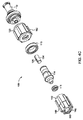
Referring to FIG. 4B, the
引き続き図4Bを参照すると、第2のコネクタ112は中間部114に連結される。1つの実施形態において、第2のコネクタ112は、取り外し可能または取り外し不能に中間部114と結合される独立部品として形成されてもよい。あるいは、第2のコネクタ112は、中間部114と一体的に形成されてもよい。中間部114は一般に、第2のコネクタ112上で環状端部壁152との封止界面を形成するために構成された半径方向面150を有する遠位端を有する筒状構造を有する。Oリングなどのガスケット116は、第2のコネクタ112と中間部114との間の封止界面を密封する。ガスケット116は、中間部114の半径方向面150と第2のコネクタ112の環状端部壁152との間に配置される。ガスケット116は望ましくは、ゴムなどの可撓性および弾性の材料から作られ、第2のコネクタ112と中間部114との間の界面を密封する。
With continued reference to FIG. 4B, the
引き続き図4Bを参照すると、リング118が、第2のコネクタ112と中間部114とを連結する。リング118は実質的に環状に形成され、第2のコネクタ112を中間部114に連結するための連結部材154を形成する。1つの実施形態において、リング118は、第2のコネクタ112と中間部114とを取り外し不能に連結する。別の実施形態において、第2のコネクタ112と中間部114とは取り外し可能に連結される。たとえば、リング118は、第2のコネクタ112に完全に螺着されたとき、リング118が中間部114を第2のコネクタ112に付勢するように、連結部材154を介して第2のコネクタ112に螺合されてもよい。このようにして、ガスケット116は、第2のコネクタ112と中間部114との間で圧縮され、その間に封止界面を提供する。
With continued reference to FIG. 4B, a
引き続き図4Bを参照すると、スリーブ120は、中間部114上で凹部122に係合することによって、中間部114に固定される。凹部122は望ましくは、中間部114の外周の少なくとも一部を囲み、中間部114の周辺部分に対して、半径方向内向きにくぼみを作る。スリーブ120は、凹部122に係合する唇縁124を含み、スリーブ120と中間部114との間の相対的な軸方向の動きを防止する。唇縁124は、スリーブ120の本体から半径方向内向きに延在し、凹部122内に受け入れられるように形成される。唇縁124は望ましくは、スリーブ120の外周の少なくとも一部を囲み、スリーブ120の周辺部分に対して、半径方向内向きに突出する。唇縁124の少なくとも一部は、凹部122の周縁まわりで半径方向に受け入れられる。
With continued reference to FIG. 4B, the
第2のコネクタ112と同様に、第1のコネクタ110は一般に、その中心軸に沿って延在する流体チャネル108を有する筒状構造を有する。第1のコネクタ110は、中心軸に沿って延在する中央管腔156を有する。中央管腔156は、中央管腔156のまわりで同軸である環状スカート158によって囲まれる。環状スカート158は、第1のコネクタ110が中間部114に対して螺進することができるように、スリーブ120に螺合するために構成される雄ねじ160を有する。中央管腔156の遠位端は、以下に記載されるように、中間部114に配置される逆止弁と相互作用するために構成される。中央管腔156の近位端は、(図3に示される)流体入口ライン32と連結するためのルアータイプコネクタ164を有する。
Similar to the
スリーブ120は一般に、中間部114および第1のコネクタ110の外周のまわりで延在するように形成される筒状構造を有する。スリーブ120の外部は、半径方向外向きに延在する1つまたは複数の突起162を有する。突起162は、ボーラス制御装置100の取り扱いを容易にするために構成される。たとえば、突起162が、使用者によって握持される把持面を提供し、(図3に示される)流体入口ライン32との連結を容易にしてもよい。
The
第1のコネクタ110と中間部114との間の界面は、Oリングなどのガスケット126で密封される。図4Bに示される実施形態において、ガスケット126は、中間部114の外周のまわりで半径方向に配置される。しかし、代替的な実施形態において、ガスケット126は、第1のコネクタ110の内周上に設けられてもよい。当業者は、任意の他の密封メカニズムが、中間部114と第1のコネクタ110との間の界面を密封するために用いられてもよいことを理解するであろう。
The interface between the
スリーブ120は、第1のコネクタ110の外周上のねじ160に対応する、その内周に沿ったねじ128を含む。よって、第1のコネクタ110は、弁本体102の近位端104と遠位端106との間で、スリーブ120に対して軸方向に可動である。キャップ132は、スリーブ120の近位端に設けられ、第1のコネクタ110がスリーブ120から完全にねじ戻されることを防止する。図4A〜4Cは、スリーブ120と第1のコネクタ110との間のねじ連結を示すが、任意のその他のタイプの機械的連結が用いられてもよい。たとえば、スリーブ120および第1のコネクタ110は、摺動、摩擦適合連結で連結されてもよい。
The
引き続き図4Bを参照すると、圧縮可能逆止弁134が、中間部114を貫通する空胴166内に配置される。空胴166は、空胴166が中間部114を貫通する流体チャネル108の部分を形成するように、ボーラス制御装置100の中心軸と整列する。圧縮可能逆止弁134は望ましくは、その外径が、流体が逆止弁134のまわりおよび空胴166の中を通るように空胴166の内径よりわずかに小さくなるように寸法が決められる。1つの実施形態において、図5B〜5Cを参照して以下で説明されるように、空胴166は、それは、第1の半径を有する複数の突起、および第1の半径より大きい第2の半径を有する複数の凹部を形成するように、正弦波形状の断面を有してもよい。逆止弁134は、突起の間で保持されるように、空胴166内に配置されてもよい。たとえば、逆止弁134の外径は、対向する突起の間の距離以下でもよい。複数の凹部は、逆止弁134のまわりに流体経路を形成する。逆止弁134は、中間部114の遠位壁138と第1のコネクタ110の遠位突起140との間の流体チャネル108内に保持される。
With continued reference to FIG. 4B, a
逆止弁134は、逆止弁134を貫通する複数の開口部136を含む。複数の開口部136は、逆止弁134の長手方向長さに沿って離間し、逆止弁134の直径の少なくとも一部で半径方向に貫通する。別の実施形態において、逆止弁134は、それを貫通する任意の開口部が空いた一体構造を有してもよい。
The
圧縮可能逆止弁134は望ましくは、流体圧が作用するとき、少なくとも部分的に長手方向に圧縮可能なエラストマー部である。注入手順の間、流体は、第1のコネクタ110に入る前に、(図3に示される)流体入口ライン32を通って、圧力下で付勢される。流体が第1のコネクタ110の中央管腔156を通って移動すると、流体は逆止弁134の近位面168に係合する。最初、近位面168は遠位突起140の遠位端に係合し、中間部114への流体の通過を遮断する。流体圧が高まると、逆止弁134の近位面168上の力は増加する。その圧縮可能な性質のために、近位面168は遠位方向に付勢され、それによって、近位面168と遠位突起140の遠位端との間に間隙が作成される。たとえば典型的な注入手順の間など、十分な流体圧が近位面168上に与えられるときのみ、このような間隙が形成される。次いで、加圧流体は、逆止弁134のまわりに移動し、患者に送達するためにボーラス制御装置100を通って移動する。たとえば、加圧流体は、逆止弁134を囲む複数の凹部を通って流れる可能性がある。注入手順が完了した後、逆止弁134の弾力性により、近位面168が遠位突起140の遠位端に係合してさらなる流体がボーラス制御装置100を通って流れることを防止するように軸方向に広がる。このようにして、加圧流体のボーラスがそれを通って送達されたあと、任意の過剰な流体がボーラス制御装置100を通って流れることは防止される。
The
第1のコネクタ110とスリーブ120との間のねじ連結により、中間部114の遠位壁138と第1のコネクタ110の遠位突起140との間の逆止弁134の初期圧縮を、調整することができる。逆止弁134の圧縮を調整することによって、逆止弁134の近位面168が遠位方向に圧縮されるクラック圧を調整することができる。このようにして、逆止弁134は、中間部114の遠位壁138と第1のコネクタ110の遠位突起140との間で軸方向に圧縮することによって、より強固にでき、それによって、逆止弁134と遠位突起140との間の間隙を開けるために、より高い圧力を必要とする。反対に、逆止弁134は、中間部114の遠位壁138と第1のコネクタ110の遠位突起140との間で軸方向に伸長することによって、より軟化でき、それによって、逆止弁134と遠位突起140との間の間隙を開けるために、より低い圧力を必要とする。逆止弁134の剛性は、第1のコネクタ110に対してスリーブ120を回転させることによって調整することができる。
A threaded connection between the
図5A〜5Hを参照すると、ボーラス制御装置200が、第2の実施形態によって示される。図5Hは、流体経路セット16に関連するボーラス制御装置200を示す。本明細書に記載されるように、ボーラス制御装置200は、医療当業者にとって容易に明らかであるように、(図1に示される)流体注入システム10への連結が意図される。ボーラス制御装置200は、遠位端206の反対側に近位端204を有する弁本体202を含む。弁本体202は、それを通る流体チャネル208を形成し、近位端204から遠位端206への流体の通過を可能とする。第1のコネクタ210は近位端204に設けられて、流体入口ライン(図示せず)に連結するために構成される。たとえば、第1のコネクタ210は、手動または自動の造影剤注入メカニズムなどの注入装置に連結された流体入口ラインの対応するルアータイプコネクタの雌端部に連結するための雄ルアータイプコネクタでもよい。第2のコネクタ212は遠位端206に設けられて、カテーテル(図示せず)などの流体出口ラインに連結するために構成される。第1のコネクタ210と同様に、第2のコネクタ212は、注入部位に導く流体出口ラインの対応するルアータイプコネクタの雄端部に連結するための雌ルアータイプコネクタでもよい。あるいは、第1のコネクタ210は雌ルアータイプコネクタでもよく、第2のコネクタ212は雄ルアータイプコネクタでもよい。さらに別の実施形態において、第1および第2のコネクタ210、212はどちらも、雄または雌のルアータイプコネクタでもよい。当業者は、第1のコネクタ210および第2のコネクタ212が、(図5Hに示される)流体経路セット16の複数の構成部品を連結するための、医療業界で周知の任意のタイプの機械式コネクタとして具現化されてもよいことを理解するであろう。
Referring to FIGS. 5A-5H, a
図5D〜5Gを参照すると、第2のコネクタ212は一般に、その中心軸に沿って延在する流体チャネル208を有する筒状構造を有する。第2のコネクタ212は、中心軸に沿って延在する中央管腔242を有する。中央管腔242は、中央管腔242のまわりで同軸である環状スカート244によって囲まれる。環状スカート244は、(図3に示される)流体出口ライン36に連結するために構成される雌ねじ246を有する。あるいは、環状スカート244は、雄ねじを有してもよい。第2のコネクタ212の外部は、半径方向外向きに延在する1つまたは複数の突起248を有する。突起248は、ボーラス制御装置200の取り扱いを容易にするために構成される。たとえば、突起248が、使用者によって握持される把持面を提供し、流体出口ライン36との連結を容易にしてもよい。
Referring to FIGS. 5D-5G, the
引き続き図5D〜5Gを参照すると、第2のコネクタ212は中間部214に連結される。1つの実施形態において、第2のコネクタ212は、取り外し可能または取り外し不能に中間部214と結合される独立部品として形成されてもよい。あるいは、第2のコネクタ212は、中間部214と一体的に形成されてもよい。中間部214は一般に、第2のコネクタ212上で環状端部壁252との封止界面を形成するために構成される半径方向面250を有する遠位端を有する筒状構造を有する。ガスケット216は、中間部214の半径方向面250と第2のコネクタ212の環状端部壁252との間に配置される。ガスケット216は望ましくは、ゴムなどの可撓性および弾性の材料から作られ、第2のコネクタ212と中間部214との間の界面を密封する。
With continued reference to FIGS. 5D-5G, the
引き続き図5D〜5Gを参照すると、リング218が、第2のコネクタ212と中間部214とを連結する。リング218は実質的に環状に形成され、第2のコネクタ212を中間部214に連結するための連結部材254を形成する。1つの実施形態において、リング218は、第2のコネクタ212と中間部214とを取り外し不能に連結する。別の実施形態において、第2のコネクタ212と中間部214とは取り外し可能に連結される。たとえば、リング218は、第2のコネクタ212に完全に螺着されたとき、リング218が中間部214を第2のコネクタ212に付勢するように、連結部材254を介して第2のコネクタ212に螺合されてもよい。このようにして、ガスケット216は、第2のコネクタ212と中間部214との間で圧縮され、その間に封止界面を提供する。
With continued reference to FIGS. 5D-5G, a
特に図5Dを参照すると、ボーラス制御装置200は、逆止弁234を調節可能に制御するための調整メカニズム220を含み、システム容量による、注入システム(図示せず)に格納されてもよい過剰な流体の任意の滴下を防止する。調整メカニズム220は、リング218と第1のコネクタ210との間に配置される。調整メカニズム220は、カムエレメント226を有する弁棒224を受けるように適合される空胴266を有する筐体222を含む。弁棒224およびカムエレメント226は、ボーラス制御装置200を通る流体流れの方向に、略直交する方向で、空胴266内に受け入れられる。弁棒224の一端は、筐体222の(図5Dおよび5Fに示される)凹部228の中に受け入れられ、一方、弁棒224の反対側の端部は、弁キャップ230上の開口部を貫通する。シール231は、弁棒224と弁キャップ230との間の界面に設けられてもよい。別の実施形態において、弁棒224は、凹部228と筐体222の一部との間に固定されてもよい。弁ハンドル232は、弁ハンドル232の回転により空胴266内の弁棒224が回転するように、弁棒224に連結される。弁棒224がその縦軸まわりに回転すると、カムエレメント226は、弁棒224の回転に対して偏心経路をたどる。1つの実施形態において、ハンドル232は、弁棒224を回転させるために、調整メカニズム220の筐体222上に直接、設けられてもよく、それによって、圧縮可能逆止弁の圧縮を調整する。1つの実施形態において、ハンドル232は、筐体222の近位端と並ぶ第1の位置から、筐体222の遠位端と並ぶ第2の位置までの180度の回転によって回転可能である。停止部材(図示せず)が、ハンドル232または弁棒224の回転運動を制限するために設けられてもよい。筐体222は、ハンドル232の位置に基づき、圧縮可能逆止弁の「剛性」を示す(図5B〜5Cに示される)表示部270を含んでもよい。たとえば、表示部270は、圧縮可能逆止弁のクラッキング圧に対応する目盛りの形態でもよい。
With particular reference to FIG. 5D, the
第2のコネクタ212と同様に、第1のコネクタ210は一般に、その中心軸に沿って延在する流体チャネル208を有する筒状構造を有する。第1のコネクタ210は、環状スカート258によって形成される中央管腔256を有する。中央管腔256の近位端は、(図5Hに示される)流体入口ライン32と連結するためのルアータイプ連結264を有する。
Similar to the
引き続き図5Dを参照すると、圧縮可能逆止弁234は、筐体222の空胴266と第1のコネクタ210との間のチャネル267内に配置される。チャネル267は、チャネル267がボーラス制御装置200を貫通する流体チャネル208の部分を形成するように、ボーラス制御装置200の中心軸と整列する。圧縮可能逆止弁234は望ましくは、その外径が、流体が逆止弁234のまわりおよび空胴266の中を通るようにチャネル267の内径よりわずかに小さくなるように寸法が決められる。逆止弁234は、第1のコネクタ210の遠位突起240とカムエレメント226との間のチャネル267内で保持される。図5B〜5Cに示される1つの実施形態において、チャネル267は、それは、第1の半径を有する複数の突起、および第1の半径より大きい第2の半径を有する複数の凹部を形成するように、正弦波形状の断面を有してもよい。逆止弁234は、突起の間で保持されるように、チャネル267内に配置されてもよい。たとえば、逆止弁234の外径は、対向する突起の間の距離以下でもよい。複数の凹部は、逆止弁234のまわりで流体経路を形成する。
With continued reference to FIG. 5D, the
逆止弁234は、逆止弁234を貫通する複数の開口部236を含む。複数の開口部236は、逆止弁234の長手方向長さに沿って離間し、逆止弁234の直径の少なくとも一部で半径方向に貫通する。別の実施形態において、逆止弁234は、それを貫通する任意の開口部が空いた一体構造を有してもよい。
The
圧縮可能逆止弁234は、望ましくは流体圧が作用するとき、少なくとも部分的に長手方向に圧縮可能なエラストマー部である。注入手順の間、流体は、第1のコネクタ210に入る前に、(図5Hに示される)流体入口ライン32を通って、圧力下で付勢される。流体が第1のコネクタ210の中央管腔256を通って移動すると、流体は逆止弁234の近位面268に係合する。最初、近位面268は遠位突起240の遠位端に係合し、中間部214への流体の通過を遮断する。流体圧が高まると、逆止弁234の近位面268上の力は増加する。その圧縮可能な性質のために、近位面268は遠位方向に付勢され、それによって、近位面268と遠位突起240の遠位端との間に間隙が作成される。たとえば典型的な注入手順の間など、十分な流体圧が近位面268上に与えられるときのみ、このような間隙が形成される。次いで、加圧流体は、逆止弁234のまわりに移動し、患者に送達するためにボーラス制御装置200を通って移動する。たとえば、加圧流体は、逆止弁234を囲む複数の凹部を通って流れる可能性がある。注入手順が完了した後、逆止弁234の弾力性により、近位面268が遠位突起240の遠位端に係合してさらなる流体がボーラス制御装置200を通って流れることを防止するように軸方向に広がる。このようにして、加圧流体のボーラスがそれを通って送達されたあと、任意の過剰な流体がボーラス制御装置200を通って流れることは防止される。
The
カムエレメント226の偏心運動により、カムエレメント226と第1のコネクタ210の遠位突起240との間の逆止弁234の初期圧縮を、調整することができる。逆止弁234の圧縮を調整することによって、逆止弁234の近位面268が遠位方向に圧縮されるクラック圧を調整することができる。このようにして、逆止弁234は、カムエレメント226と第1のコネクタ210の遠位突起240との間で軸方向に圧縮することによって、より強固にでき、それによって、逆止弁234と遠位突起240との間の間隙を開けるために、より高い圧力を必要とする。反対に、逆止弁234は、中間部214の上の遠位突起240と第1のコネクタ210の遠位突起240との間で軸方向に伸長することによって、より軟化でき、それによって、逆止弁234と遠位突起240との間の間隙を開けるために、より低い圧力を必要とする。
Due to the eccentric movement of the
図5D〜5Eを参照すると、ボーラス制御装置200の調整メカニズム220は第1の位置に示され、カムエレメント226が第1のコネクタ210に最も近い位置に配置される最大圧縮設定に圧縮可能逆止弁234が調整されている。図5G〜5Hに示すように、カムエレメント226が第1のコネクタ210から最も遠く離れた位置に配置されるように、圧縮可能逆止弁234の圧縮を、弁棒224を回すことによって減少させることができる。この位置において、圧縮可能逆止弁234は、図5D〜5Eに示される位置に対して圧縮が小さい。圧縮可能逆止弁234の圧縮の調整は、処置タイプ、流体経路セットのタイプ、カテーテルサイズ、注入流体のタイプ、および圧力パラメータを含む種々のシステム変数に関して、クラック圧を調整することが望ましい。
Referring to FIGS. 5D-5E, the
図6A〜6Cを参照すると、ボーラス制御装置300が、第3の実施形態によって示される。本明細書に記載されるように、ボーラス制御装置300は、医療当業者にとって容易に明らかであるように、(図1に示される)流体注入システム10への連結が意図される。ボーラス制御装置300は、図4A〜4Cを参照して先に記載されたボーラス制御装置100と同様である。図6A〜6Cの参照番号302〜368は、図4A〜4Cの参照番号102〜168と同一の構成部品を示すために用いられる。2つの実施形態の間の相対的な差異のみ、以下で論じられる。
With reference to FIGS. 6A-6C, a
図4A〜4Cの逆止弁134の剛性は、第1のコネクタ110に対してスリーブ120を回転させることによって調整することができるが、図6A〜6Cのボーラス制御装置300は、リング318とスリーブ320との間に配置される調整リング372を含む。調整リング372は、中間部314を係合するために構成される中央開口部374を有する環形状を有する。中央開口部374は望ましくは、調整リング372が中間部314に対して回転可能でないように非円形である。1つの実施形態において、調整リング372は、調整リング372が中間部314に対して回転可能でないように、中間部314と摩擦係合される円形中央開口部374を有してもよい。調整リング372は、ハンドル332の位置に基づき、圧縮可能逆止弁334の「剛性」を示す表示部370を有する。たとえば、表示部370は、圧縮可能逆止弁334のクラッキング圧に対応する目盛りの形態でもよい。
While the stiffness of the
調整リング372の回転は、中間部314の対応する回転を引き起こし、それは第1のコネクタ310をスリーブ320に対して回転させる。第1のコネクタ310とスリーブ320との間のねじ連結により、中間部314の遠位壁338と第1のコネクタ310の遠位突起340との間の逆止弁334の初期圧縮を、調整することができる。逆止弁334の圧縮を調整することによって、逆止弁334の近位面368が遠位方向に圧縮されるクラック圧を調整することができる。このようにして、逆止弁334は、中間部314の遠位壁338と第1のコネクタ310の遠位突起340との間で軸方向に圧縮することによって、より強固にでき、それによって、逆止弁334と遠位突起340との間の間隙を開けるために、より高い圧力を必要とする。反対に、逆止弁334は、中間部314の遠位壁338と第1のコネクタ310の遠位突起340との間で軸方向に伸長することによって、より軟化でき、それによって、逆止弁334と遠位突起340との間の間隙を開けるために、より低い圧力を必要とする。
The rotation of the
流体経路セットボーラス制御装置のさまざまな実施形態が、上記説明において提供されたが、当業者は、本開示の範囲および精神を逸脱しない範囲で、これらの実施形態に対する変形および変更を行ってもよい。たとえば、本開示は、可能な限り、任意の実施形態の1つまたは複数の特徴を任意の他の実施形態の1つまたは複数の特徴に組み合わせることができることを意図すると理解されるべきである。したがって、前述の説明は限定的というよりも説明的なものとして意図される。 While various embodiments of the fluid path set bolus control device have been provided in the above description, those skilled in the art may make variations and modifications to these embodiments without departing from the scope and spirit of the present disclosure. . For example, it is to be understood that this disclosure contemplates where possible one or more features of any embodiment can be combined with one or more features of any other embodiment. Accordingly, the foregoing description is intended as illustrative rather than limiting.
10 ・・・流体送達システム
12 ・・・電動式流体注入器
14 ・・・注射器
16 ・・・流体経路セット
18 ・・・手動制御装置
20 ・・・流体制御モジュール
22 ・・・第1の注入流体
24 ・・・第2の注入流体
26 ・・・第1の流体ライン
28 ・・・第2の流体ライン
30 ・・・流体コネクタ
32 ・・・流体入口ライン
34 ・・・弁
36 ・・・流体出口ライン
38 ・・・コネクタ
100、200、300 ・・・ボーラス制御装置
102、202 ・・・弁本体
108、208 ・・・流体チャネル
110、210、310 ・・・第1のコネクタ
112、212 ・・・第2のコネクタ
114、214、314 ・・・中間部
116、126、216 ・・・ガスケット
118、218、318 ・・・リング
120、320 ・・・スリーブ
132 ・・・キャップ
134、234、334 ・・・圧縮可能逆止弁
142、242 ・・・中央管腔
144、244 ・・・環状スカート
150、250 ・・・半径方向面
152、252 ・・・環状端部壁
154、254 ・・・連結部材
156、256 ・・・中央管腔
158、258 ・・・環状スカート
164 ・・・ルアータイプコネクタ
220 ・・・調整メカニズム
222 ・・・筐体
224 ・・・弁棒
226 ・・・カムエレメント
230 ・・・弁キャップ
231 ・・・シール
232 ・・・弁ハンドル
236 ・・・開口部
266 ・・・空胴
264 ・・・ルアータイプ連結
267 ・・・チャネル 332 ・・・ハンドル
372 ・・・調整リング
374 ・・・中央開口部
DESCRIPTION OF
Claims (19)
遠位端の反対側に近位端を有し、それを通して流体チャネルを形成した弁本体と、
流体入口ラインに連結するために構成された前記近位端の第1のコネクタと、
流体出口ラインに連結するために構成された前記遠位端の第2のコネクタと、
前記弁本体の前記近位端および前記遠位端の間で前記流体チャネル内に配置された圧縮可能逆止弁であって、前記圧縮可能逆止弁は、圧縮可能な材料で形成された本体と、前記流体チャネルの流れ方向を横切る方向に前記本体を通り延在する複数の開口部とを有し、前記本体は、前記流体チャネル内の流体圧に応じて、前記弁本体の前記近位端および前記遠位端の間で長手方向に圧縮可能である、圧縮可能逆止弁と、
前記圧縮可能逆止弁の圧縮を変えるよう構成された調整メカニズムと、
を備え、
前記調整メカニズムの動きによって前記圧縮可能逆止弁の材料の圧縮を増加または減少させることによって、前記流体チャネルを通る流体流れを許容するために前記圧縮可能逆止弁が開くクラッキング圧を増加または減少させる、ボーラス制御装置。 A bolus control device used with an infusion device, the bolus control device comprising:
A valve body having a proximal end opposite the distal end and through which a fluid channel is formed;
A first connector at the proximal end configured for connection to a fluid inlet line;
A second connector at the distal end configured for connection to a fluid outlet line;
A compressible check valve disposed in the fluid channel between the proximal end and the distal end of the valve body, wherein the compressible check valve is formed of a compressible material. And a plurality of openings extending through the body in a direction transverse to the flow direction of the fluid channel, wherein the body is proximate to the valve body in response to fluid pressure in the fluid channel. A compressible check valve that is longitudinally compressible between an end and said distal end;
An adjustment mechanism configured to change the compression of the compressible check valve;
With
Increasing or decreasing the compression pressure of the compressible check valve to allow fluid flow through the fluid channel by increasing or decreasing compression of the compressible check valve material by movement of the adjustment mechanism A bolus control device.
流体入口ラインと、
流体出口ラインと、
前記流体入口ラインと前記流体出口ラインとの間に配置されたボーラス制御装置であって、該ボーラス制御装置は、
遠位端の反対側に近位端を有し、それを通して流体チャネルを形成した弁本体と、
前記流体入口ラインに連結するために構成された前記近位端の第1のコネクタと、
前記流体出口ラインに連結するために構成された前記遠位端の第2のコネクタと、
前記弁本体の前記近位端および前記遠位端の間で前記流体チャネル内に配置された圧縮可能逆止弁であって、圧縮可能な材料で形成された本体と、前記流体チャネルの流れ方向を横切る方向に前記本体を通り延在する複数の開口部とを有する圧縮可能逆止弁と、
前記圧縮可能逆止弁の圧縮を変えるよう構成された調整メカニズムと、
を備えたボーラス制御装置と、を備え、
前記圧縮可能逆止弁の材料は、前記流体チャネル内の流体圧に応じて、前記弁本体の前記近位端および前記遠位端の間で長手方向に可逆的に圧縮可能であり、
前記調整メカニズムの動きが前記材料の圧縮を増加または減少させることにより、前記弁本体を通る流体の加圧送達中に前記流体チャネルを通る流体流れを許容するために前記圧縮可能逆止弁が開くクラッキング圧が増加または減少する、流体経路セット。 A fluid path set for use with an infusion device, the fluid path set comprising:
A fluid inlet line;
A fluid outlet line;
A bolus control device disposed between the fluid inlet line and the fluid outlet line, the bolus control device comprising:
A valve body having a proximal end opposite the distal end and through which a fluid channel is formed;
A first connector at the proximal end configured to couple to the fluid inlet line;
A second connector at the distal end configured to couple to the fluid outlet line;
A compressible check valve disposed in the fluid channel between the proximal end and the distal end of the valve body, the body formed of a compressible material; and a flow direction of the fluid channel A compressible check valve having a plurality of openings extending through the body in a direction across the body;
An adjustment mechanism configured to change the compression of the compressible check valve;
A bolus control device comprising:
The compressible check valve material is reversibly compressible longitudinally between the proximal end and the distal end of the valve body in response to fluid pressure within the fluid channel;
Movement of the adjustment mechanism increases or decreases compression of the material, thereby opening the compressible check valve to allow fluid flow through the fluid channel during pressurized delivery of fluid through the valve body. A fluid path set in which the cracking pressure increases or decreases.
遠位端の反対側に近位端を有し、それを通して流体チャネルを形成した弁本体と、
流体入口ラインに連結するために構成された前記近位端の第1のコネクタと、
流体出口ラインに連結するために構成された前記遠位端の第2のコネクタと、
前記弁本体の前記近位端および前記遠位端の間で前記流体チャネル内に配置された圧縮可能逆止弁であって、圧縮可能な材料で形成された本体を有する圧縮可能逆止弁と、
前記第1のコネクタに対する前記圧縮可能逆止弁の圧縮を変える調整メカニズムであって、偏心カム要素と、前記偏心カム要素を有する弁棒を受けるように構成された空胴を有する筐体とを備える調整メカニズムと、
を備え、
前記圧縮可能逆止弁の材料は、前記流体チャネル内の流体圧に応じて、前記弁本体の前記近位端および前記遠位端の間で長手方向に可逆的に圧縮可能であり、
前記調整メカニズムの動きが前記材料の圧縮を増加または減少させることにより、前記弁本体を通る流体の加圧送達中に前記流体チャネルを通る流体流れを許容するために前記圧縮可能逆止弁が開くクラッキング圧が増加または減少する、ボーラス制御装置。 A bolus control device used in an infusion device, the bolus control device comprising:
A valve body having a proximal end opposite the distal end and through which a fluid channel is formed;
A first connector at the proximal end configured for connection to a fluid inlet line;
A second connector at the distal end configured for connection to a fluid outlet line;
A compressible check valve disposed in the fluid channel between the proximal end and the distal end of the valve body, the compressible check valve having a body formed of a compressible material; ,
An adjustment mechanism for altering compression of the compressible check valve relative to the first connector, comprising: an eccentric cam element; and a housing having a cavity configured to receive a valve stem having the eccentric cam element. An adjustment mechanism to provide,
With
The compressible check valve material is reversibly compressible longitudinally between the proximal end and the distal end of the valve body in response to fluid pressure within the fluid channel;
Movement of the adjustment mechanism increases or decreases compression of the material, thereby opening the compressible check valve to allow fluid flow through the fluid channel during pressurized delivery of fluid through the valve body. Bolus control device that increases or decreases cracking pressure.
Applications Claiming Priority (3)
| Application Number | Priority Date | Filing Date | Title |
|---|---|---|---|
| US201361818056P | 2013-05-01 | 2013-05-01 | |
| US61/818,056 | 2013-05-01 | ||
| PCT/US2014/035892 WO2014179326A1 (en) | 2013-05-01 | 2014-04-29 | Fluid path set bolus control device |
Publications (2)
| Publication Number | Publication Date |
|---|---|
| JP2016516550A JP2016516550A (en) | 2016-06-09 |
| JP6492059B2 true JP6492059B2 (en) | 2019-03-27 |
Family
ID=51843891
Family Applications (1)
| Application Number | Title | Priority Date | Filing Date |
|---|---|---|---|
| JP2016511804A Active JP6492059B2 (en) | 2013-05-01 | 2014-04-29 | Fluid path set bolus control device |
Country Status (4)
| Country | Link |
|---|---|
| US (2) | US10441775B2 (en) |
| EP (1) | EP2991721B1 (en) |
| JP (1) | JP6492059B2 (en) |
| WO (1) | WO2014179326A1 (en) |
Families Citing this family (25)
| Publication number | Priority date | Publication date | Assignee | Title |
|---|---|---|---|---|
| ATE480278T1 (en) | 2005-09-12 | 2010-09-15 | Unomedical As | INTRODUCTION SYSTEM FOR AN INFUSION SET WITH A FIRST AND SECOND SPRING UNIT |
| CA2792138A1 (en) | 2010-03-30 | 2011-10-06 | Unomedical A/S | Medical device |
| US10194938B2 (en) | 2011-03-14 | 2019-02-05 | UnoMedical, AS | Inserter system with transport protection |
| EP2763723B1 (en) | 2011-10-05 | 2016-04-13 | Unomedical A/S | Inserter for simultaneous insertion of multiple transcutaneous parts |
| EP2583715A1 (en) | 2011-10-19 | 2013-04-24 | Unomedical A/S | Infusion tube system and method for manufacture |
| EP3258987B1 (en) * | 2015-02-19 | 2018-09-26 | UMC Utrecht Holding B.V. | Device for administration of fluid medicaments |
| AR106795A1 (en) * | 2015-11-25 | 2018-02-21 | Bayer Healthcare Llc | SYRINGE AND CONNECTOR SYSTEM |
| WO2017125817A1 (en) | 2016-01-19 | 2017-07-27 | Unomedical A/S | Cannula and infusion devices |
| KR101833899B1 (en) | 2016-02-18 | 2018-03-05 | (주)선메딕스 | Blood access apparatus with pressor sensor and drug filter |
| EP3423130B1 (en) | 2016-03-03 | 2025-05-14 | Bayer Healthcare LLC | System and method for improved fluid delivery in multi-fluid injector systems |
| EP3538182A1 (en) | 2016-11-14 | 2019-09-18 | Bayer Healthcare LLC | Methods and systems for verifying the contents of a syringe used for medical fluid delivery |
| CN110809482B (en) | 2017-08-31 | 2023-03-07 | 拜耳医药保健有限公司 | Fluid injector system volume compensation system and method |
| AU2018323442B2 (en) | 2017-08-31 | 2024-06-27 | Bayer Healthcare Llc | Fluid path impedance assessment for improving fluid delivery performance |
| JP7493337B2 (en) | 2017-08-31 | 2024-05-31 | バイエル・ヘルスケア・エルエルシー | Method for dynamic pressure control in a fluid injector system - Patents.com |
| AU2018326485B2 (en) | 2017-08-31 | 2024-01-04 | Bayer Healthcare Llc | Injector pressure calibration system and method |
| CN110891630B (en) | 2017-08-31 | 2022-04-26 | 拜耳医药保健有限公司 | System and method for drive member positioning and fluid injector system mechanical calibration |
| CA3097557A1 (en) | 2018-04-19 | 2019-10-24 | Bayer Healthcare Llc | System and method for air detection in fluid injector |
| EP3796954B1 (en) | 2018-07-31 | 2023-05-03 | Fresenius Medical Care Holdings, Inc. | Rotary valves for dialysis systems |
| JP2021536278A (en) | 2018-08-28 | 2021-12-27 | バイエル・ヘルスケア・エルエルシーBayer HealthCare LLC | Fluid injector system with improved specific performance |
| CA3110859A1 (en) | 2018-08-28 | 2020-03-05 | Bayer Healthcare Llc | Fluid injector system, method of preventing fluid backflow, and computer program product |
| US11666745B2 (en) * | 2018-12-07 | 2023-06-06 | Fresenius Medical Care Holdings, Inc. | Rotary valves for managing fluid flows in medical systems |
| CA3141608A1 (en) | 2019-05-20 | 2020-11-26 | Unomedical A/S | Rotatable infusion device and methods thereof |
| US12558468B2 (en) | 2019-12-12 | 2026-02-24 | Fresenius Medical Care Holdings, Inc. | Blood treatment systems |
| CN117618762B (en) * | 2023-11-16 | 2024-07-30 | 锐嘉(宜兴)科技有限公司 | Multi-size applicability needle-free dosing connector |
| US12594374B2 (en) * | 2024-03-15 | 2026-04-07 | Asset Medical, Inc. | Stackable manifolds for medical fluids |
Family Cites Families (37)
| Publication number | Priority date | Publication date | Assignee | Title |
|---|---|---|---|---|
| US3889710A (en) * | 1972-11-07 | 1975-06-17 | Julien H Brost | Check valve with elastomeric valve element |
| US4550749A (en) | 1984-03-12 | 1985-11-05 | C. R. Bard, Inc. | Adjustable check valve |
| JPS6266064U (en) * | 1985-10-15 | 1987-04-24 | ||
| US4749003A (en) * | 1987-01-22 | 1988-06-07 | Filtertek, Inc. | Center flow check valve |
| US4919167A (en) * | 1989-03-17 | 1990-04-24 | Manska Wayne E | Check valve |
| US5289849A (en) * | 1990-05-29 | 1994-03-01 | Paradis Joseph R | Control of fluid flow |
| DK0988871T3 (en) * | 1991-12-18 | 2004-05-24 | Icu Medical Inc | Method of transferring fluid |
| US5788215A (en) * | 1995-12-29 | 1998-08-04 | Rymed Technologies | Medical intravenous administration line connectors having a luer or pressure activated valve |
| TW390942B (en) * | 1996-04-22 | 2000-05-21 | Schwinn Cycling & Fitness Inc | Combination pump head |
| US5989240A (en) * | 1998-02-27 | 1999-11-23 | Becton, Dickson And Company | Adaptor for mounting a fluid handling device on a catheter tubing |
| US6706022B1 (en) | 1999-07-27 | 2004-03-16 | Alaris Medical Systems, Inc. | Needleless medical connector with expandable valve mechanism |
| IT1311348B1 (en) * | 1999-11-12 | 2002-03-12 | Borla Ind | CHECK VALVE FOR MEDICAL INFUSION LINES AND SIMILAR. |
| US6695817B1 (en) * | 2000-07-11 | 2004-02-24 | Icu Medical, Inc. | Medical valve with positive flow characteristics |
| US7094216B2 (en) | 2000-10-18 | 2006-08-22 | Medrad, Inc. | Injection system having a pressure isolation mechanism and/or a handheld controller |
| JP4357764B2 (en) | 2001-04-16 | 2009-11-04 | 株式会社ニフコ | Rotary actuator for hinge |
| JP2002331032A (en) * | 2001-05-11 | 2002-11-19 | Otsuka Techno Kk | Backflow prevention tool and manufacturing method thereof and medical tool using the same |
| US20070161970A1 (en) * | 2004-04-16 | 2007-07-12 | Medrad, Inc. | Fluid Delivery System, Fluid Path Set, and Pressure Isolation Mechanism with Hemodynamic Pressure Dampening Correction |
| US8540698B2 (en) | 2004-04-16 | 2013-09-24 | Medrad, Inc. | Fluid delivery system including a fluid path set and a check valve connector |
| US20080154214A1 (en) * | 2006-12-22 | 2008-06-26 | Medrad, Inc. | Flow Based Pressure Isolation and Fluid Delivery System Including Flow Based Pressure Isolation |
| US7563249B2 (en) | 2002-12-20 | 2009-07-21 | Medrad, Inc. | Syringe having an alignment flange, an extending lip and a radial expansion section of reduced wall thickness |
| US7553294B2 (en) | 2002-05-30 | 2009-06-30 | Medrad, Inc. | Syringe plunger sensing mechanism for a medical injector |
| US7666169B2 (en) | 2003-11-25 | 2010-02-23 | Medrad, Inc. | Syringe and syringe plungers for use with medical injectors |
| JP4548823B2 (en) | 2004-03-31 | 2010-09-22 | サーパス工業株式会社 | Safety valve device |
| US7556619B2 (en) | 2004-04-16 | 2009-07-07 | Medrad, Inc. | Fluid delivery system having a fluid level sensor and a fluid control device for isolating a patient from a pump device |
| US20060161115A1 (en) * | 2004-11-05 | 2006-07-20 | Fangrow Thomas F | Soft-grip medical connector |
| EP1980291A1 (en) * | 2006-01-17 | 2008-10-15 | JMS Co., Ltd. | Water passage control device and medical infusion circuit using the same |
| CN104162200B (en) * | 2006-02-09 | 2018-03-27 | 德卡产品有限公司 | peripheral system |
| EP2026859A4 (en) * | 2006-06-14 | 2015-02-18 | Acist Medical Sys Inc | FLUID PURGING IN A MEDICAL INJECTION SYSTEM |
| CN102202705A (en) * | 2008-10-31 | 2011-09-28 | 马林克罗特公司 | Multi-dose injection system |
| US8454579B2 (en) * | 2009-03-25 | 2013-06-04 | Icu Medical, Inc. | Medical connector with automatic valves and volume regulator |
| ES2464046T3 (en) | 2009-07-24 | 2014-05-30 | Bayer Medical Care Inc. | Multi-fluid medical injector system |
| US8603047B2 (en) * | 2010-12-15 | 2013-12-10 | Infusion Innovations | Devices, assemblies and methods for controlling fluid flow |
| WO2012155035A1 (en) | 2011-05-12 | 2012-11-15 | Medrad, Inc. | Fluid injection system having various systems for controlling an injection procedure |
| WO2014004511A1 (en) * | 2012-06-28 | 2014-01-03 | Saint-Gobain Performance Plastics Corporation | Polymer bellows spring |
| US20140102561A1 (en) * | 2012-10-11 | 2014-04-17 | Diba Industries, Inc. | Quick-release connectors and connection assemblies for fluidic coupling |
| US9259527B2 (en) | 2012-10-17 | 2016-02-16 | Bayer Healthcare Llc | Fluid delivery system with high and low pressure hand manifold |
| JP6266064B2 (en) | 2016-09-14 | 2018-01-24 | Kddi株式会社 | Authentication method, access point, and program for connecting third-party wireless terminal to user-owned access point |
-
2014
- 2014-04-29 JP JP2016511804A patent/JP6492059B2/en active Active
- 2014-04-29 EP EP14791318.0A patent/EP2991721B1/en active Active
- 2014-04-29 WO PCT/US2014/035892 patent/WO2014179326A1/en not_active Ceased
- 2014-04-29 US US14/888,298 patent/US10441775B2/en active Active
-
2019
- 2019-10-14 US US16/600,961 patent/US11202898B2/en active Active
Also Published As
| Publication number | Publication date |
|---|---|
| US10441775B2 (en) | 2019-10-15 |
| US11202898B2 (en) | 2021-12-21 |
| WO2014179326A1 (en) | 2014-11-06 |
| EP2991721A4 (en) | 2017-01-25 |
| EP2991721B1 (en) | 2020-03-11 |
| US20160058995A1 (en) | 2016-03-03 |
| US20200038647A1 (en) | 2020-02-06 |
| EP2991721A1 (en) | 2016-03-09 |
| JP2016516550A (en) | 2016-06-09 |
Similar Documents
| Publication | Publication Date | Title |
|---|---|---|
| JP6492059B2 (en) | Fluid path set bolus control device | |
| EP2908884B1 (en) | Fluid delivery system with high and low pressure hand manifold | |
| EP3151907B1 (en) | Tubing assembly | |
| US8852167B2 (en) | Medical connector | |
| US7972305B2 (en) | Drug supply system for CED (convection-enhanced delivery) catheter infusions | |
| US11826541B2 (en) | Sliding syringe cap for separate filling and delivery | |
| JP6945661B2 (en) | Priming system for injection equipment | |
| US7704230B2 (en) | Pressurized fluid reservoir for an infusion system | |
| US20210030957A1 (en) | Dual fluid injection system | |
| CN1738655A (en) | Distribution device for a supply network for supply of medical fluids to a patient | |
| CN109843369B (en) | Fluid control valve and manifold | |
| CN108904970A (en) | A kind of multipurpose medical anti-reflective stream connector | |
| JP2012055592A (en) | Drug solution administration appliance | |
| HK1212934B (en) | Fluid delivery system with high and low pressure hand manifold | |
| KR20170041393A (en) | Rate of flow controlling type drug dosage controller |
Legal Events
| Date | Code | Title | Description |
|---|---|---|---|
| A711 | Notification of change in applicant |
Free format text: JAPANESE INTERMEDIATE CODE: A711 Effective date: 20161115 |
|
| A621 | Written request for application examination |
Free format text: JAPANESE INTERMEDIATE CODE: A621 Effective date: 20170410 |
|
| A977 | Report on retrieval |
Free format text: JAPANESE INTERMEDIATE CODE: A971007 Effective date: 20180319 |
|
| A131 | Notification of reasons for refusal |
Free format text: JAPANESE INTERMEDIATE CODE: A131 Effective date: 20180326 |
|
| A521 | Request for written amendment filed |
Free format text: JAPANESE INTERMEDIATE CODE: A523 Effective date: 20180622 |
|
| A131 | Notification of reasons for refusal |
Free format text: JAPANESE INTERMEDIATE CODE: A131 Effective date: 20181029 |
|
| A521 | Request for written amendment filed |
Free format text: JAPANESE INTERMEDIATE CODE: A523 Effective date: 20190118 |
|
| TRDD | Decision of grant or rejection written | ||
| A01 | Written decision to grant a patent or to grant a registration (utility model) |
Free format text: JAPANESE INTERMEDIATE CODE: A01 Effective date: 20190204 |
|
| A61 | First payment of annual fees (during grant procedure) |
Free format text: JAPANESE INTERMEDIATE CODE: A61 Effective date: 20190304 |
|
| R150 | Certificate of patent or registration of utility model |
Ref document number: 6492059 Country of ref document: JP Free format text: JAPANESE INTERMEDIATE CODE: R150 |
|
| R250 | Receipt of annual fees |
Free format text: JAPANESE INTERMEDIATE CODE: R250 |
|
| R250 | Receipt of annual fees |
Free format text: JAPANESE INTERMEDIATE CODE: R250 |
|
| R250 | Receipt of annual fees |
Free format text: JAPANESE INTERMEDIATE CODE: R250 |
|
| R250 | Receipt of annual fees |
Free format text: JAPANESE INTERMEDIATE CODE: R250 |
|
| R250 | Receipt of annual fees |
Free format text: JAPANESE INTERMEDIATE CODE: R250 |