JP6446843B2 - Golf club head - Google Patents
Golf club head Download PDFInfo
- Publication number
- JP6446843B2 JP6446843B2 JP2014119805A JP2014119805A JP6446843B2 JP 6446843 B2 JP6446843 B2 JP 6446843B2 JP 2014119805 A JP2014119805 A JP 2014119805A JP 2014119805 A JP2014119805 A JP 2014119805A JP 6446843 B2 JP6446843 B2 JP 6446843B2
- Authority
- JP
- Japan
- Prior art keywords
- golf club
- face plate
- club head
- head
- face
- Prior art date
- Legal status (The legal status is an assumption and is not a legal conclusion. Google has not performed a legal analysis and makes no representation as to the accuracy of the status listed.)
- Active
Links
Images




Classifications
-
- A—HUMAN NECESSITIES
- A63—SPORTS; GAMES; AMUSEMENTS
- A63B—APPARATUS FOR PHYSICAL TRAINING, GYMNASTICS, SWIMMING, CLIMBING, OR FENCING; BALL GAMES; TRAINING EQUIPMENT
- A63B53/00—Golf clubs
- A63B53/04—Heads
- A63B53/047—Heads iron-type
-
- A—HUMAN NECESSITIES
- A63—SPORTS; GAMES; AMUSEMENTS
- A63B—APPARATUS FOR PHYSICAL TRAINING, GYMNASTICS, SWIMMING, CLIMBING, OR FENCING; BALL GAMES; TRAINING EQUIPMENT
- A63B53/00—Golf clubs
- A63B53/04—Heads
- A63B53/0408—Heads characterised by specific dimensions, e.g. thickness
-
- A—HUMAN NECESSITIES
- A63—SPORTS; GAMES; AMUSEMENTS
- A63B—APPARATUS FOR PHYSICAL TRAINING, GYMNASTICS, SWIMMING, CLIMBING, OR FENCING; BALL GAMES; TRAINING EQUIPMENT
- A63B53/00—Golf clubs
- A63B53/04—Heads
- A63B53/0458—Heads with non-uniform thickness of the impact face plate
- A63B53/0462—Heads with non-uniform thickness of the impact face plate characterised by tapering thickness of the impact face plate
-
- A—HUMAN NECESSITIES
- A63—SPORTS; GAMES; AMUSEMENTS
- A63B—APPARATUS FOR PHYSICAL TRAINING, GYMNASTICS, SWIMMING, CLIMBING, OR FENCING; BALL GAMES; TRAINING EQUIPMENT
- A63B53/00—Golf clubs
- A63B53/04—Heads
- A63B53/0466—Heads wood-type
-
- A—HUMAN NECESSITIES
- A63—SPORTS; GAMES; AMUSEMENTS
- A63B—APPARATUS FOR PHYSICAL TRAINING, GYMNASTICS, SWIMMING, CLIMBING, OR FENCING; BALL GAMES; TRAINING EQUIPMENT
- A63B2209/00—Characteristics of used materials
-
- A—HUMAN NECESSITIES
- A63—SPORTS; GAMES; AMUSEMENTS
- A63B—APPARATUS FOR PHYSICAL TRAINING, GYMNASTICS, SWIMMING, CLIMBING, OR FENCING; BALL GAMES; TRAINING EQUIPMENT
- A63B53/00—Golf clubs
- A63B53/04—Heads
- A63B53/0416—Heads having an impact surface provided by a face insert
-
- A—HUMAN NECESSITIES
- A63—SPORTS; GAMES; AMUSEMENTS
- A63B—APPARATUS FOR PHYSICAL TRAINING, GYMNASTICS, SWIMMING, CLIMBING, OR FENCING; BALL GAMES; TRAINING EQUIPMENT
- A63B53/00—Golf clubs
- A63B53/04—Heads
- A63B53/0416—Heads having an impact surface provided by a face insert
- A63B53/0429—Heads having an impact surface provided by a face insert the face insert comprising two or more layers of material
-
- A—HUMAN NECESSITIES
- A63—SPORTS; GAMES; AMUSEMENTS
- A63B—APPARATUS FOR PHYSICAL TRAINING, GYMNASTICS, SWIMMING, CLIMBING, OR FENCING; BALL GAMES; TRAINING EQUIPMENT
- A63B53/00—Golf clubs
- A63B53/04—Heads
- A63B53/0458—Heads with non-uniform thickness of the impact face plate
-
- A—HUMAN NECESSITIES
- A63—SPORTS; GAMES; AMUSEMENTS
- A63B—APPARATUS FOR PHYSICAL TRAINING, GYMNASTICS, SWIMMING, CLIMBING, OR FENCING; BALL GAMES; TRAINING EQUIPMENT
- A63B53/00—Golf clubs
- A63B53/04—Heads
- A63B53/047—Heads iron-type
- A63B53/0475—Heads iron-type with one or more enclosed cavities
Landscapes
- Health & Medical Sciences (AREA)
- General Health & Medical Sciences (AREA)
- Physical Education & Sports Medicine (AREA)
- Life Sciences & Earth Sciences (AREA)
- Engineering & Computer Science (AREA)
- Wood Science & Technology (AREA)
- Golf Clubs (AREA)
Description
本発明は、ゴルフクラブヘッドに係り、特にフェース部に弾性体を介してフェースプレートが設けられているゴルフクラブヘッドに関するものである。 The present invention relates to a golf club head, and more particularly to a golf club head having a face plate provided with an elastic body at a face portion.
アイアン型ゴルフクラブヘッドは、周知の通り、平面状のフェース面を有したフェース部と、該フェース部のヒール側に連なるホゼル部とを有し、該ホゼル部にシャフト挿入穴が設けられている。このシャフト挿入穴にシャフトが挿入され、接着剤によって固着される。 As is well known, an iron type golf club head has a face portion having a flat face surface and a hosel portion connected to the heel side of the face portion, and a shaft insertion hole is provided in the hosel portion. . A shaft is inserted into the shaft insertion hole and fixed by an adhesive.
特許文献1には、打撃面プレートが衝撃吸収層によってヘッド本体の打撃面位置に貼り付けられているゴルフクラブヘッドが記載されている。
特許文献2には、ヘッド本体のフェース面側に、緩衝材からなる中間層を介在したヘッドが記載されている。 Patent Document 2 describes a head in which an intermediate layer made of a cushioning material is interposed on the face surface side of the head body.
ドライバーやフェアウェーウッドなどのウッド型ゴルフクラブヘッドとして、中空の金属製のものが広く用いられている。一般に、中空のウッド型のゴルフクラブヘッドは、ボールをヒットするためのフェース部と、ゴルフクラブヘッドの上面部を構成するクラウン部と、ゴルフクラブヘッドの底面部を構成するソール部と、ゴルフクラブヘッドのトウ側、バック側及びヒール側の側面部を構成するサイド部と、ホゼル部とを有している。この中空ゴルフクラブヘッドを構成する金属としては、アルミニウム合金、ステンレスやチタン合金が用いられているが、ドライバーの場合、近年は特にチタン合金が広く用いられている。 Hollow metal golf club heads such as drivers and fairway woods are widely used. In general, a hollow wood-type golf club head includes a face portion for hitting a ball, a crown portion constituting an upper surface portion of the golf club head, a sole portion constituting a bottom surface portion of the golf club head, and a golf club. It has a side part constituting a side part on the toe side, back side and heel side of the head, and a hosel part. As a metal constituting the hollow golf club head, an aluminum alloy, stainless steel, or titanium alloy is used. In the case of a driver, in particular, a titanium alloy has been widely used in recent years.
特許文献3には、ヘッド本体のフェース部に設けられた弾性体層と、この弾性体層の表面を覆う繊維強化樹脂層とを有するゴルフクラブヘッドが記載されている。 Patent Document 3 describes a golf club head having an elastic body layer provided on a face portion of a head body and a fiber reinforced resin layer covering the surface of the elastic body layer.
本発明は、ボールヒット時にフェースプレートが上方又は下方にスライドし、これによりバックスピン量が減少又は増加するゴルフクラブヘッドを提供することを目的とする。 It is an object of the present invention to provide a golf club head in which a face plate slides upward or downward when a ball hits, thereby reducing or increasing the backspin amount.
本発明のゴルフクラブヘッドは、ヘッド本体に弾性体を介してフェースプレートが設けられたゴルフクラブヘッドにおいて、該弾性体の材料の硬度は、ショアA硬度10以上、ショアD硬度80以下であり、該フェースプレートの後面は該ヘッド本体のフェース面に対して平行ではなく、該フェースプレートの後面と該ヘッド本体の弾性体配置面とが平行であることを特徴とするものである。 The golf club head of the present invention is a golf club head in which a face plate is provided on the head body via an elastic body, and the material of the elastic body has a Shore A hardness of 10 or more and a Shore D hardness of 80 or less, The rear surface of the face plate is not parallel to the face surface of the head main body, and the rear surface of the face plate and the elastic body arrangement surface of the head main body are parallel to each other.
本発明では、該フェースプレートは、下方ほど厚みが小さくなっていることが好ましい。 In the present invention, it is preferable that the thickness of the face plate decreases toward the bottom.
本発明では、フェースプレートの前面及び後面がいずれも平面であり、両者の交差角度θが2°以上、70°以下であることが好ましい。 In the present invention, it is preferable that both the front surface and the rear surface of the face plate are flat surfaces, and the crossing angle θ between them is 2 ° or more and 70 ° or less.
本発明では、該フェースプレートは、下方ほど厚みが大きくなっていることが好ましい。 In the present invention, it is preferable that the thickness of the face plate increases toward the bottom.
本発明では、弾性体の厚さが一様であることが好ましい。 In the present invention, it is preferable that the thickness of the elastic body is uniform.
本発明のゴルフクラブヘッドがアイアン型ゴルフクラブヘッドである場合、前記弾性体の上縁がフェースプレートの上縁よりも下位に位置していることが好ましい。 When the golf club head of the present invention is an iron type golf club head, it is preferable that the upper edge of the elastic body is positioned lower than the upper edge of the face plate.
本発明のゴルフクラブヘッドにあっては、フェースプレートがショアA硬度10以上、ショアD硬度80以下の材料を用いた弾性体を介してヘッド本体のフェース面に保持され、フェースプレートの後面はヘッド本体のフェース面に対して平行ではなく、フェースプレートの後面とヘッド本体の弾性体配置面とが平行になっており、ボールをヒットしたとき(即ちインパクト時)にフェースプレートが上方又は下方にスライドするので、バックスピン量が減少又は増加する。 In the golf club head of the present invention, the face plate is held on the face surface of the head body via an elastic body using a material having a Shore A hardness of 10 or more and a Shore D hardness of 80 or less. The back surface of the face plate and the elastic body placement surface of the head main body are not parallel to the face surface of the main body, and the face plate slides upward or downward when the ball is hit (ie during impact). Therefore, the backspin amount decreases or increases.
フェースプレートが下方ほど厚みが小さくなっている場合は、フェースプレートが一様厚さである場合に比べて、フェースプレート背面の後傾角度が大きく、インパクト時におけるフェースプレートのスライド量が大きなものとなり、バックスピン量が減少する。 When the thickness of the face plate is reduced toward the lower side, the rearward tilt angle of the rear face of the face plate is larger and the sliding amount of the face plate at the time of impact is larger than when the face plate has a uniform thickness. , The backspin amount decreases.
一方、フェースプレートが下方ほど厚みが大きくなっている場合は、フェースプレート背面が前傾し、インパクト時にフェースプレートが下方にスライドするので、バックスピン量が増加する。 On the other hand, when the thickness of the face plate increases toward the lower side, the back surface of the face plate tilts forward, and the face plate slides downward at the time of impact, so the backspin amount increases.
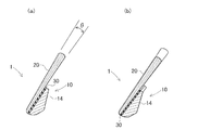
図1〜4を参照して第1発明の実施の形態に係るアイアン型ゴルフクラブヘッド1について説明する。
An iron type
このアイアン型ゴルフクラブヘッド1は、フェース部に凹陥部11(図3)が設けられたヘッド本体10と、この凹陥部11に弾性体30を介して装着されたフェースプレート20とを有する。
The iron-type
この実施の形態では、ヘッド本体10及びフェースプレート20はステンレス、軟鉄などの鉄系材料にて構成されている。ヘッド本体10のヒール側にはホゼル部12が設けられている。
In this embodiment, the
このゴルフクラブヘッド1はマッスルバック構造のものであり、ヘッド本体10の下部にふくらみを持たせた形状となっている。ヘッド本体10の下部のうちトウ・ヒール方向の中央部は板状部14となっている。
This
凹陥部11は、ヘッド本体10のトウ・ヒール方向の中央部に配置され、ヘッド本体10の上端から下端にまで設けられている。凹陥部11のトウ・ヒール方向の幅は、上下方向において均等である。板状部14の前面側において、凹陥部11の深さは、下方ほど小さくなっている。
The
板状部14よりも上位側では、凹陥部11はヘッド本体10を前後方向に貫通しており、これにより凹陥部11のトウ側及びヒール側にそれぞれトウ側起立部15及びヒール側起立部16が形成されている。この貫通した構造により、ヘッド上部の厚さが厚くなり過ぎないようにすることができる。
On the upper side of the plate-
凹陥部11のうち板状部14の前面は上向き傾斜面よりなる。この板状部14の前面に弾性体30が配置されている。この弾性体30の前面にフェースプレート20が配置されている。板状部14の前面とフェースプレート20の背面は、平行になっている。弾性体30は接着剤により、板状部14の前面とフェースプレート20の背面に固定されてもよい。フェースプレート20のトウ・ヒール方向の幅は凹陥部11のトウ・ヒール方向の幅と同じか、若干小さくなっている。フェースプレート20は、静的な状態で弾性体30とのみ接触するように固定すると、よりスライドしやすい構造が得られる。弾性体30を介してフェースプレート20を凹陥部11に装着した状態において、フェースプレート20の上縁及び下縁はヘッド本体10の上縁及び下縁と同じになっている。また、この弾性体30を介してフェースプレート20を装着した状態において、フェースプレート20の前面と、そのトウ側及びヒール側のヘッド本体10の前面とは同一平面上にある。図示は省略するが、フェースプレート20の前面には溝(スコアライン)が設けられている。
The front surface of the plate-
フェースプレート20の背面は、フェースプレート20の前面に対して平行ではなく、傾斜(後傾)している。フェースプレート20の前面に対する、フェースプレート20の背面の傾斜角度について、下限としては2°以上、好ましくは10°以上であり、上限としては70°以下、好ましくは60°以下である。傾斜角度が小さすぎると、スライドの効果が得られにくい場合があり、大きすぎると、ヘッド重量が重くなりすぎる等、ヘッド設計に影響を与える場合がある。
The back surface of the
フェースプレート20の厚さは、上縁部から下縁部にかけて徐々に小さくなっている。フェースプレート20の下縁におけるフェースプレート20の厚さについて、下限として1mm以上、好ましくは3mm以上であり、上限としては7mm以下、好ましくは5mm以下である。フェースプレート20の厚さが小さすぎると強度が不足してしまう場合があり、大きすぎると、スライドの効果が低下したり、ヘッド重量が重くなりすぎたりする等、ヘッド設計に影響を与える場合がある。凹陥部11及びフェースプレート20のトウ・ヒール方向の幅について、特に制限はないが、下限として10mm以上、好ましくは20mm以上であり、上限としては100mm以下である。
The thickness of the
弾性体30の材料の硬度は、下限値としてショアA硬度10以上、好ましくはショアA硬度30以上、上限値としてはショアD硬度80以下、好ましくはショアD硬度70以下である。硬度が小さすぎると、フェースプレートやヘッド本体との接着力が低下してしまう場合があり、大きすぎると、スライドの効果が得られなくなる場合がある。弾性体30の材料としては、ゴム又は樹脂等からなる材料が挙げられる。ゴムとしては、例えば天然ゴム、ポリブタジエンゴム、スチレンブタジエンゴム、イソプレンゴム等が挙げられる。樹脂としては、例えばアイオノマー樹脂、ウレタン樹脂、ポリエステル樹脂、ポリアミド樹脂等が挙げられる。特に、ウレタン樹脂が好適である。弾性体30の厚さは下限として0.1mm以上、好ましくは0.3mm以上であり、上限としては5mm以下、好ましくは3mm以下である。厚さが小さすぎると、スライドの効果が得られにくくなってしまう場合があり、大きすぎると、ゴルフボールの初速が低下し過ぎてしまう場合がある。この実施形態では弾性体30の厚さは全体として均一としているが、厚さを部分的に異ならせてもよい。
The hardness of the material of the
このように構成されたゴルフクラブヘッド1を有するゴルフクラブにあっては、ボールを打ったインパクト時に弾性体30が凹陥部11に沿って剪断変形し、フェースプレート20が上方にスライドする。つまり、フェースプレート20の背面が前面よりも上記角度θだけ後傾しているため、インパクト時にフェースプレート20が凹陥部11に沿って上方にスライドしやすくなっている。これにより、ボールに生じるバックスピン量が減少し、飛距離が増大する。なお、この実施形態のアイアン型ゴルフクラブは、ミドルアイアン又はロングアイアンのヘッドに用いる事で、バックスピン量の減少による飛距離の増大を得る事ができる。
In the golf club having the
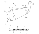
図5を参照して別の実施の形態に係るゴルフクラブヘッド1Aについて説明する。このゴルフクラブヘッド1Aでは、フェースプレート20Aの両側端面21を、前面側ほどフェースプレート20Aのトウ・ヒール方向幅が小さくなるように傾斜したテーパ面としている。ヘッド本体10の凹陥部11の両側面もこれに係合したアンダーカット状としている。これにより、フェースプレート20Aのフェース面と垂直方向への脱落が防止される。
A
なお、図示は省略するが、フェースプレートのトウ・ヒール方向の両側端面の後縁側に凸条部を設け、凹陥部11に該凸条部がスライド可能に係合する凹条部を設け、フェースプレートの脱落を防止するようにしてもよい。
Although not shown in the figure, a convex strip is provided on the rear edge side of both end faces in the toe / heel direction of the face plate, and a concave strip is provided on the
また、これら以外の、フェースプレートの上下方向のスライドにあまり影響しないような、フェースプレートとヘッド本体を結合する手段を設けてもよい。例えば、フェースプレートと弾性体とヘッド本体を、トウ端とヒール端においてネジで結合するようにしてもよい。 In addition, other means for connecting the face plate and the head body may be provided so as not to significantly affect the vertical sliding of the face plate. For example, the face plate, the elastic body, and the head main body may be coupled with screws at the toe end and the heel end.
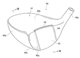
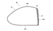
上記実施の形態はアイアン型ゴルフクラブヘッドに関するものであるが、本発明はウッド型ゴルフクラブヘッドや、ユーティリティ型ゴルフクラブヘッドにも適用できる。図6,7はウッド型ゴルフクラブヘッド40を示すものである。このゴルフクラブヘッド40は、中空ドライバーヘッドであり、フェース部40aと、クラウン部40bと、ソール部40cと、サイド部40dと、ホゼル部40eとを有する。
Although the above embodiment relates to an iron type golf club head, the present invention can also be applied to a wood type golf club head and a utility type golf club head. 6 and 7 show a wood type
このゴルフクラブヘッド40は、ヘッド本体41と、弾性体42と、フェースプレート43とで構成されている。ヘッド本体41及びフェースプレート43はチタン合金製であるが、これに限定されない。
The
フェース部40aに、上下方向に延在する凹陥部44が設けられ、この凹陥部44に弾性体42が配置され、弾性体42の前面にフェースプレート43が配置されている。ヘッド本体41における弾性体42の配置面とフェースプレート43の背面とは平行になっている。弾性体42は接着剤により、ヘッド本体41の弾性体配置面とフェースプレート43の背面に固定されてもよい。フェースプレート43及び凹陥部44はクラウン部40bからソール部40cにまで達している。
A
フェースプレート43の背面は、フェースプレート43の前面に対して平行ではなく、傾斜(後傾)している。フェースプレート43の前面に対する、フェースプレート43の背面の傾斜角度について、下限としては2°以上、好ましくは10°以上であり、上限としては70°以下、好ましくは60°以下である。傾斜角度が小さすぎると、スライドの効果が得られなくなる場合があり、大きすぎると、ヘッド重量が重くなりすぎる等、ヘッド設計に影響を与える場合がある。
The back surface of the
凹陥部44は、下方ほど深さが小さくなっている。フェースプレート43は、下方ほど厚みが小さくなっている。フェースプレート43のトウ・ヒール方向の幅員は、凹陥部44のトウ・ヒール方向の幅員と同じか、若干小さくなっている。フェースプレート43は、静的な状態で弾性体42とのみ接触するように固定すると、よりスライドしやすい構造が得られる。
The depth of the recessed
フェースプレート43及び凹陥部44の幅員について、下限として10mm以上、好ましくは20mm以上であり、上限としては120mm以下である。弾性体42の厚みは全体として均一である。弾性体42の厚みは下限として0.1mm以上、好ましくは0.3mm以上であり、上限としては5mm以下、好ましくは3mm以下である。厚さが小さすぎると、スライドの効果が得られにくくなってしまう場合があり、大きすぎると、ゴルフボールの初速が低下し過ぎてしまう場合がある。
Regarding the width of the
弾性体42を介してフェースプレート43を装着した状態において、フェースプレート43の前面と、そのトウ側及びヒール側のヘッド本体41の前面とは同一平面上にある。この実施形態では弾性体42の厚さは全体として均一としているが、厚さを部分的に異ならせてもよい。
In a state where the
このゴルフクラブヘッド40を有するゴルフクラブでボールを打った場合においても、インパクト時にフェースプレート43が上方にスライドするので、ボールのバックスピン量が減少し、飛距離が増大する。
Even when a ball is hit with a golf club having the
図8を参照して第2発明の実施の形態に係るアイアン型ゴルフクラブヘッド1Bについて説明する。
An iron type
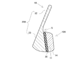
このアイアン型ゴルフクラブヘッド1Bは、フェース部に凹陥部11が設けられたヘッド本体10Bと、このヘッド本体10Bの凹陥部11に弾性体30を介して装着されたフェースプレート20Bとを有する。フェースプレート20Bの上部22の厚さは、上下方向においてほぼ均等である。フェースプレート20Bの下部23の厚さは、下縁部から上方に向って徐々に小さくなっている。フェースプレート20Bの下縁における下部23の厚さについて、特に制限はないが、下限としては1.5mm以上、好ましくは3mm以上であり、上限としては15mm以下、好ましくは10mm以下である。フェースプレート20Bの上縁における上部22の厚さについて、特に制限はないが、下限としては1mm以上、好ましくは2mm以上であり、上限としては5mm以下、好ましくは4mm以下である。
This iron type
凹陥部11のうち板状部14の前面は下向き傾斜面となっている。この板状部14の前面に弾性体30が配置されている。この弾性体30の前面にフェースプレート20Bの下部23が配置されている。板状部14の前面と、下部23の背面は平行になっている。弾性体30は、接着剤により、板状部14の前面と下部23の背面に固定されてもよい。
The front surface of the plate-
下部23の背面の上下方向の長さは、板状部14の前面の上下方向の長さよりも大きく、上部22と板状部14との間にはスペースSが設けられ、フェースプレート20Bが下方にスライドした際に、板状部14及び弾性体30と上部22とが接触しないようになっている。
The length of the back surface of the
下部23の背面は、フェースプレート20Bの前面に対して平行ではなく、傾斜(前傾)している。フェースプレート20Bの前面に対する、下部23の背面の傾斜角度について、下限としては2°以上、好ましくは10°以上であり、上限としては70°以下、好ましくは60°以下である。傾斜角度が小さすぎると、スライドの効果が得られなくなる場合があり、大きすぎるとヘッド重量が重くなりすぎる等、ヘッド設計に影響を与える場合がある。
The back surface of the
このゴルフクラブヘッド1Bのその他の構成はゴルフクラブヘッド1又は1Aと同様である。
Other configurations of the
このように構成されたゴルフクラブヘッド1Bを有するゴルフクラブにあっては、板状部14の前面が下向き傾斜面となっているところから、ボールを打ったインパクト時に弾性体30が凹陥部11に沿って剪断変形し、フェースプレート20Bが若干下方にスライドする。つまり、フェースプレート20Bの下部23の背面が前面よりも前傾しているため、インパクト時にフェースプレート20Bが凹陥部11に沿って下方にスライドしやすくなっている。これにより、ボールに生じるバックスピン量が増加し、ボールが止まり易くなる。なお、この実施形態のアイアン型ゴルフクラブは、ショートアイアン又はミドルアイアンのヘッドに用いることで、バックスピン量が増加し、落下点の近くでボールを止めることが容易となる。
In the golf club having the
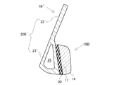
図9を参照して別の実施の形態に係るゴルフクラブヘッド1B’について説明する。このゴルフクラブヘッド1B’では、フェースプレート20B’の下部23’に中空部25を設けた中空構造とし、フェースプレート20B’を軽量化している。このゴルフクラブヘッド1B’でもゴルフクラブヘッド1Bと同様の効果が奏される。
A
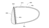
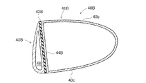
図8,9の実施の形態はアイアン型ゴルフクラブヘッドに関するものであるが、第2発明はウッド型ゴルフクラブヘッドや、ユーティリティ型ゴルフクラブヘッドにも適用できる。図10,11はウッド型ゴルフクラブヘッド40A,40Bを示すものである。ゴルフクラブヘッド40Aはフェースプレート43Aを中実としたものである。ゴルフクラブヘッド40Bは、フェースプレート43Bに中空部48を設けた中空構造とし、フェースプレート43Bを軽量化している。
Although the embodiment of FIGS. 8 and 9 relates to an iron type golf club head, the second invention can be applied to a wood type golf club head and a utility type golf club head. 10 and 11 show wood type golf club heads 40A and 40B. The
このゴルフクラブヘッド40A,40Bは、ヘッド本体41A,41Bと、弾性体42A、42Bと、フェースプレート43A、43Bとで構成されている。ヘッド本体41A、41B及びフェースプレート43A、43Bはチタン合金製であるが、これに限定されない。弾性体42A、42Bの材料の硬度は、下限としてショアA硬度10以上、好ましくはショアA硬度30以上であり、上限としてショアD硬度80以下、好ましくはショアD硬度70以下である。
The golf club heads 40A and 40B are composed of head
ヘッド本体41A、41Bのフェース面は下向き傾斜面よりなる。このフェース面に、上下方向に延在する凹陥部44A、44Bが設けられ、この凹陥部44A、44Bに弾性体42A、42Bが配置され、弾性体42A、42Bの前面にフェースプレート43A、43Bが配置されている。ヘッド本体41A、41Bにおける弾性体42A、42Bの配置面とフェースプレート43A、43Bの背面とは平行になっている。弾性体42A、42Bは接着剤により、ヘッド本体41A、41Bの弾性体配置面とフェースプレート43A、43Bの背面に固定されてもよい。フェースプレート43A、43B及び凹陥部44A、44Bはクラウン部40bの前縁からソール部40cの前縁にまで達している。
The face surfaces of the head
凹陥部44A、44Bは、下方ほど深さが大きくなっている。フェースプレート43A、43Bは、上方ほど厚みが小さくなっている。フェースプレート43A、43Bの背面は、フェースプレート43A、43Bの前面に対して平行ではなく、傾斜(前傾)している。フェースプレート43Aは中実構造であり、フェースプレート43Bは中空部48を有した中空構造である。
The depth of the recessed
このゴルフクラブヘッド40A、40Bを有するゴルフクラブでボールを打った場合においても、インパクト時にフェースプレート43A、43Bが下方にスライドするので、ボールのバックスピン量が増加し、ボールが止まり易くなる。この実施形態のウッド型ゴルフクラブヘッド40A、40Bは、フェアウェーウッドに用いることで、バックスピン量の増加により、ボールを止め易くすることができる。
Even when a ball is hit with a golf club having the golf club heads 40A and 40B, the
[実験1]
図12(a),(d)に示すチタン製の長方形の板50(80mmW×80mmH×5.8mmt)を前面が鉛直面に対し角度αだけ後傾するようにして、4つ角をネジで土台(図示せず)に固定した。このチタン板の前面に対しゴルフボール(ブリヂストンスポーツ株式会社製「X01z」又は「2013年PHYZ」)を速度43m/sにて衝突させ、弾ね返ったボールの初速、打出し角及びスピン量を測定した。結果を表1に示す。なお、上記角度α=5°、10°又は15°(PHYZの場合は5°のみ)とした。
[Experiment 1]
A rectangular plate 50 (80 mmW × 80 mmH × 5.8 mmt) made of titanium shown in FIGS. 12A and 12D is tilted with respect to a vertical plane by an angle α, and four corners are screwed. Fixed to a base (not shown). A golf ball (“X01z” or “2013 PHYZ” manufactured by Bridgestone Sports Co., Ltd.) made at the front surface of the titanium plate is collided at a speed of 43 m / s, and the initial speed, launch angle and spin amount of the bounced ball are set. It was measured. The results are shown in Table 1. The angle α was set to 5 °, 10 ° or 15 ° (only 5 ° in the case of PHYZ).
[実験2]
図12(b),(e)に示す、チタン板61,62を厚さ0.5mmの樹脂板63を介して張り合せた、チタン板50と同一寸法の複合板60を用いた。この複合板60を実験1と同様に前面60aを後傾させて固定し、同様にしてボールを衝突させ、弾ね返ったボールの初速、打出し角及びスピン量を測定した。角度α=5°とした。結果を表1に示す。樹脂板63としては、ショアD硬度30のウレタン樹脂板又はショアD硬度68のウレタン樹脂板を用いた。チタン板61,62と樹脂板63との張り合せにはエポキシ系接着剤を用いた。
[Experiment 2]
A
チタン板61,62は同一形状であり、張り合せ面の複合板前面60aに対する角度は15°とした。なお、この張り合せ面は、複合板前面を鉛直とした状態では下向きであり、鉛直面に対し15°前傾(−15°後傾)している。
The
衝突実験では、複合板前面60aが鉛直面に対し角度α=5°だけ後傾するようにしているため、樹脂板前面(張り合せ面)の後傾角度は−10°(=α−15°)となる。樹脂板前面の後傾角度がマイナスであることは、樹脂板の前面が下向きであることを表す。
In the collision experiment, the composite plate
[実験3]
図12(c),(f)に示すように、チタン板71,72を厚さ0.5mmの樹脂板73を介して張り合せた複合板70を用いたこと以外は実験2と同様にしてボールを衝突させ、弾ね返ったボールの初速、打出し角β及びスピン量を測定した。角度α=5°、10°又は15°(PHYZの場合は5°のみ)とした。結果を表1に示す。
[Experiment 3]
As shown in FIGS. 12C and 12F, the same procedure as in Experiment 2 was performed except that a
なお、この複合板70は、図12(b),(e)の複合板60を上下反転させたこと以外は同一材料、同一構造のものである。複合板70の前面70aを鉛直とした状態では、張り合せ面は鉛直面よりも上向きとなっており、その角度は15°である。
The
衝突実験では、複合板前面70aが鉛直面に対し角度α=5°、10°又は15°だけ後傾するようにしているため、樹脂板前面(張り合せ面)の後傾角度は20°、25°又は30°(=α+15°)となる。樹脂板前面の後傾角度がプラスであることは、樹脂板の前面が上向きであることを表す。
In the collision experiment, since the composite plate
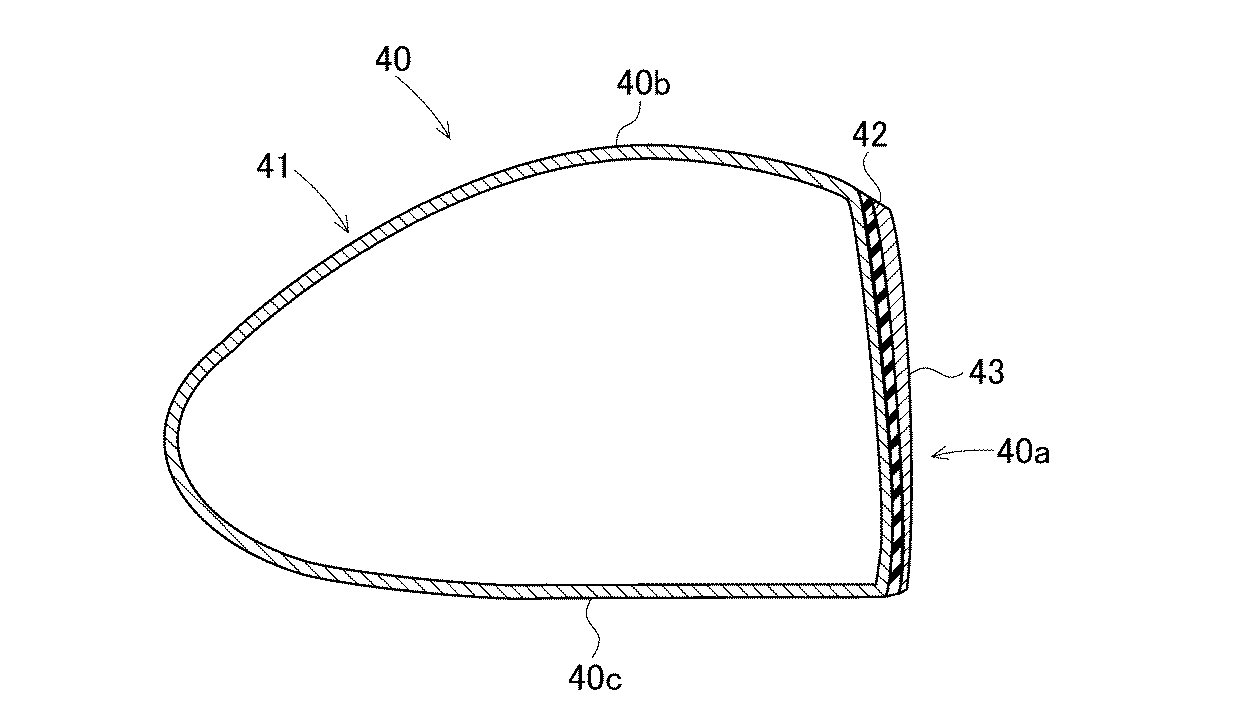
表1の通り、樹脂板を図12(c)の後傾斜構造にした場合、図12(a)の単板構造に比べてスピン量が少なく、打出し角も大きい。これに対し、樹脂板が図12(b)の前傾斜構造であると、図12(a)の単板構造に比べてスピン量が多い。 As shown in Table 1, when the resin plate has a rear inclined structure shown in FIG. 12C, the spin amount is small and the launch angle is large as compared with the single plate structure shown in FIG. On the other hand, when the resin plate has the forward inclined structure of FIG. 12B, the spin amount is larger than that of the single plate structure of FIG.
以上のことから、第1発明構造(樹脂板後傾斜構造)とすることによりスピン量が減少し、第2発明構造(樹脂板前傾斜構造)とすることによりスピン量が増加することが裏付けられた。 From the above, it was confirmed that the spin amount decreased by adopting the first invention structure (inclined structure after the resin plate) and increased by adopting the second invention structure (inclined structure before the resin plate). .
1,1A,1B,1B’,40,40A,40B ゴルフクラブヘッド
10,10B,10B’,41,41A,41B ヘッド本体
11,44,44A,44B 凹陥部
20,20A,20B,20B’,43,43A,43B フェースプレート
30,42,42A,42B 弾性体
1, 1A, 1B, 1B ', 40, 40A, 40B
Claims (7)
該ゴルフクラブヘッドはアイアン型ゴルフクラブヘッドであり、
該弾性体の材料の硬度は、ショアA硬度10以上、ショアD硬度80以下であり、
該フェースプレートの後面は該ヘッド本体のフェース面に対して平行ではなく、
該フェースプレートの後面と該ヘッド本体の弾性体配置面とが平行であり、
該弾性体の上縁が該フェースプレートの上縁よりも下位に位置していることを特徴とするゴルフクラブヘッド。 In a golf club head in which a face plate is provided on the head body via an elastic body,
The golf club head is an iron type golf club head,
The elastic material has a Shore A hardness of 10 or more and a Shore D hardness of 80 or less,
The rear surface of the face plate is not parallel to the face surface of the head body,
Ri parallel der the elastic body disposed surface of the face and the head main body after said face plate,
Golf club head to the upper edge of the elastic body and said that you have located in the lower than the upper edge of the face plate.
該フェースプレートのトウ・ヒール方向の両側端面の後縁側に凸条部を設け、該凹陥部に該凸条部に係合する凹条部を設けたことを特徴とするゴルフクラブヘッド。A golf club head, wherein a convex strip is provided on the rear edge side of both end surfaces in the toe-heel direction of the face plate, and a concave strip that engages with the convex strip is provided in the concave portion.
該凹陥部は、該ヘッド本体のトウ・ヒール方向の中央部に配置され、The recessed portion is disposed at the center of the head body in the toe-heel direction,
該ヘッド本体の下部のうちトウ・ヒール方向の中央部は板状部となっており、Of the lower part of the head body, the central part in the toe-heel direction is a plate-like part,
該板状部よりも上位側の該凹陥部は該ヘッド本体を前後方向に貫通していることを特徴とするゴルフクラブヘッド。The golf club head characterized in that the concave portion on the upper side of the plate-like portion penetrates the head body in the front-rear direction.
Priority Applications (2)
| Application Number | Priority Date | Filing Date | Title |
|---|---|---|---|
| JP2014119805A JP6446843B2 (en) | 2014-06-10 | 2014-06-10 | Golf club head |
| US14/689,692 US9539478B2 (en) | 2014-06-10 | 2015-04-17 | Golf club head |
Applications Claiming Priority (1)
| Application Number | Priority Date | Filing Date | Title |
|---|---|---|---|
| JP2014119805A JP6446843B2 (en) | 2014-06-10 | 2014-06-10 | Golf club head |
Related Child Applications (1)
| Application Number | Title | Priority Date | Filing Date |
|---|---|---|---|
| JP2018220291A Division JP6642687B2 (en) | 2018-11-26 | 2018-11-26 | Golf club head |
Publications (2)
| Publication Number | Publication Date |
|---|---|
| JP2015231485A JP2015231485A (en) | 2015-12-24 |
| JP6446843B2 true JP6446843B2 (en) | 2019-01-09 |
Family
ID=54768762
Family Applications (1)
| Application Number | Title | Priority Date | Filing Date |
|---|---|---|---|
| JP2014119805A Active JP6446843B2 (en) | 2014-06-10 | 2014-06-10 | Golf club head |
Country Status (2)
| Country | Link |
|---|---|
| US (1) | US9539478B2 (en) |
| JP (1) | JP6446843B2 (en) |
Families Citing this family (11)
| Publication number | Priority date | Publication date | Assignee | Title |
|---|---|---|---|---|
| US10398951B2 (en) * | 2011-11-28 | 2019-09-03 | Acushnet Company | Co-forged golf club head and method of manufacture |
| JP6786267B2 (en) | 2016-06-15 | 2020-11-18 | ブリヂストンスポーツ株式会社 | Golf club head |
| KR101728074B1 (en) * | 2016-09-13 | 2017-04-18 | 이윤경 | Putter head for golf and golf putter having the same |
| JP7003444B2 (en) * | 2017-05-18 | 2022-01-20 | 住友ゴム工業株式会社 | Golf club head |
| JP6917785B2 (en) | 2017-06-05 | 2021-08-11 | ブリヂストンスポーツ株式会社 | Golf club head |
| US10881926B1 (en) | 2019-07-29 | 2021-01-05 | Taylor Made Golf Company, Inc. | Iron golf club head |
| US11130023B1 (en) | 2020-05-29 | 2021-09-28 | Sumitomo Rubber Industries, Ltd. | Golf club head |
| US11491377B1 (en) * | 2021-12-28 | 2022-11-08 | Acushnet Company | Golf club head having multi-layered striking face |
| US11850461B2 (en) * | 2022-03-11 | 2023-12-26 | Acushnet Company | Golf club head having supported striking face |
| US20240207696A1 (en) * | 2022-12-21 | 2024-06-27 | Karsten Manufacturing Corporation | Golf club head with descending face thickness |
| JP7626952B1 (en) | 2023-08-30 | 2025-02-05 | 株式会社プロギア | Golf Club Head |
Family Cites Families (24)
| Publication number | Priority date | Publication date | Assignee | Title |
|---|---|---|---|---|
| US708575A (en) * | 1901-01-21 | 1902-09-09 | William Mules | Golf-club. |
| US2429351A (en) * | 1944-01-01 | 1947-10-21 | Frank J Werner Jr | Golf club |
| US3084940A (en) * | 1960-07-06 | 1963-04-09 | Eric B Cissel | Golf club heads |
| US3368812A (en) * | 1964-06-29 | 1968-02-13 | William K. Baldwin Sr. | Wood-type golf club with detachable face plate |
| JPS58166365U (en) | 1982-04-30 | 1983-11-05 | ヤマハ株式会社 | golf iron club head |
| JPS6113984A (en) | 1984-06-28 | 1986-01-22 | 住友ゴム工業株式会社 | Golf club head |
| JPH01131682A (en) | 1987-11-17 | 1989-05-24 | Mizuno Corp | Golf club head |
| US5083778A (en) * | 1988-02-18 | 1992-01-28 | Douglass Michael B | Golf club putter head |
| JPH01126269U (en) * | 1988-02-20 | 1989-08-29 | ||
| US4884808A (en) * | 1988-03-24 | 1989-12-05 | Retzer Jerome E | Golf club with head having exchangeable face plates |
| US5141231A (en) * | 1990-12-14 | 1992-08-25 | Elizabeth Ann Martin | Golf club face shield |
| JPH05305161A (en) | 1992-04-28 | 1993-11-19 | Maruman Golf Corp | Golf club head |
| FR2693378A1 (en) * | 1992-07-10 | 1994-01-14 | Taylor Made Golf Inc | Improvement for "iron" type golf club head. |
| US5403007A (en) * | 1992-07-28 | 1995-04-04 | Chen; Archer C. C. | Golf club head of compound material |
| JPH0666730U (en) * | 1993-03-10 | 1994-09-20 | ヤマハ株式会社 | Golf club head |
| US6001030A (en) * | 1998-05-27 | 1999-12-14 | Delaney; William | Golf putter having insert construction with controller compression |
| JP3091025U (en) | 2002-06-27 | 2003-01-17 | 陳 晴▲祺▼ | Golf club head |
| US7281990B2 (en) * | 2004-12-22 | 2007-10-16 | Head Technology Gmbh, Ltd. | Method and apparatus for elastic tailoring of golf club impact |
| JP4411990B2 (en) * | 2004-02-03 | 2010-02-10 | ブリヂストンスポーツ株式会社 | Golf club head |
| JP4677793B2 (en) | 2005-01-24 | 2011-04-27 | 横浜ゴム株式会社 | Iron golf club head and iron golf club |
| US8277337B2 (en) * | 2009-07-22 | 2012-10-02 | Bridgestone Sports Co., Ltd. | Iron head |
| US8790192B2 (en) * | 2010-06-29 | 2014-07-29 | Bridgestone Sports Co., Ltd. | Putter head |
| JP2012010767A (en) * | 2010-06-29 | 2012-01-19 | Bridgestone Sports Co Ltd | Putter head |
| US8622850B2 (en) * | 2010-12-17 | 2014-01-07 | Bridgestone Sports Co., Ltd. | Putter head |
-
2014
- 2014-06-10 JP JP2014119805A patent/JP6446843B2/en active Active
-
2015
- 2015-04-17 US US14/689,692 patent/US9539478B2/en not_active Expired - Fee Related
Also Published As
| Publication number | Publication date |
|---|---|
| JP2015231485A (en) | 2015-12-24 |
| US20150352412A1 (en) | 2015-12-10 |
| US9539478B2 (en) | 2017-01-10 |
Similar Documents
| Publication | Publication Date | Title |
|---|---|---|
| JP6446843B2 (en) | Golf club head | |
| US11273348B2 (en) | Golf club head with sound damping | |
| US7803064B2 (en) | Golf club head with multiple undercuts | |
| US9555300B2 (en) | Putter face insert | |
| US7682263B2 (en) | Golf club head | |
| JP4256206B2 (en) | Golf club head | |
| CN101031342B (en) | Muscleback iron golf club head with insert | |
| KR102026595B1 (en) | Golf club head | |
| JP5989509B2 (en) | Golf club head and golf club | |
| JP5906055B2 (en) | Golf club head and golf club | |
| EP1893308B1 (en) | Golf club | |
| US20090291775A1 (en) | Wood-type golf club head | |
| JP2005305179A (en) | Golf club head with undercut | |
| US20160158609A1 (en) | Golf club head | |
| JP4723397B2 (en) | Golf club head for putter and golf putter | |
| JP6642687B2 (en) | Golf club head | |
| US12102888B2 (en) | Putter club head with profiled face insert | |
| JP5447914B2 (en) | Wood type golf club head and wood type golf club | |
| JP2007054166A (en) | Wood type golf club head | |
| JP2015000237A (en) | Golf club head | |
| KR102030285B1 (en) | Golf club Wood Head | |
| JP2022064225A (en) | Putter head with front side member, intermediate member and rear side member | |
| JP2007037997A (en) | Iron type golf club |
Legal Events
| Date | Code | Title | Description |
|---|---|---|---|
| A621 | Written request for application examination |
Free format text: JAPANESE INTERMEDIATE CODE: A621 Effective date: 20170516 |
|
| A977 | Report on retrieval |
Free format text: JAPANESE INTERMEDIATE CODE: A971007 Effective date: 20180411 |
|
| A131 | Notification of reasons for refusal |
Free format text: JAPANESE INTERMEDIATE CODE: A131 Effective date: 20180417 |
|
| A521 | Request for written amendment filed |
Free format text: JAPANESE INTERMEDIATE CODE: A523 Effective date: 20180611 |
|
| TRDD | Decision of grant or rejection written | ||
| A01 | Written decision to grant a patent or to grant a registration (utility model) |
Free format text: JAPANESE INTERMEDIATE CODE: A01 Effective date: 20181106 |
|
| A61 | First payment of annual fees (during grant procedure) |
Free format text: JAPANESE INTERMEDIATE CODE: A61 Effective date: 20181119 |
|
| R150 | Certificate of patent or registration of utility model |
Ref document number: 6446843 Country of ref document: JP Free format text: JAPANESE INTERMEDIATE CODE: R150 |
|
| R250 | Receipt of annual fees |
Free format text: JAPANESE INTERMEDIATE CODE: R250 |
|
| R250 | Receipt of annual fees |
Free format text: JAPANESE INTERMEDIATE CODE: R250 |
|
| R250 | Receipt of annual fees |
Free format text: JAPANESE INTERMEDIATE CODE: R250 |
|
| R250 | Receipt of annual fees |
Free format text: JAPANESE INTERMEDIATE CODE: R250 |
|
| R250 | Receipt of annual fees |
Free format text: JAPANESE INTERMEDIATE CODE: R250 |