JP6425681B2 - Vehicle camera system - Google Patents
Vehicle camera system Download PDFInfo
- Publication number
- JP6425681B2 JP6425681B2 JP2016076327A JP2016076327A JP6425681B2 JP 6425681 B2 JP6425681 B2 JP 6425681B2 JP 2016076327 A JP2016076327 A JP 2016076327A JP 2016076327 A JP2016076327 A JP 2016076327A JP 6425681 B2 JP6425681 B2 JP 6425681B2
- Authority
- JP
- Japan
- Prior art keywords
- camera system
- light
- sensitivity
- region
- cut filter
- Prior art date
- Legal status (The legal status is an assumption and is not a legal conclusion. Google has not performed a legal analysis and makes no representation as to the accuracy of the status listed.)
- Expired - Fee Related
Links
Images


Classifications
-
- H—ELECTRICITY
- H04—ELECTRIC COMMUNICATION TECHNIQUE
- H04N—PICTORIAL COMMUNICATION, e.g. TELEVISION
- H04N23/00—Cameras or camera modules comprising electronic image sensors; Control thereof
- H04N23/20—Cameras or camera modules comprising electronic image sensors; Control thereof for generating image signals from infrared radiation only
-
- H—ELECTRICITY
- H04—ELECTRIC COMMUNICATION TECHNIQUE
- H04N—PICTORIAL COMMUNICATION, e.g. TELEVISION
- H04N23/00—Cameras or camera modules comprising electronic image sensors; Control thereof
- H04N23/57—Mechanical or electrical details of cameras or camera modules specially adapted for being embedded in other devices
-
- B—PERFORMING OPERATIONS; TRANSPORTING
- B62—LAND VEHICLES FOR TRAVELLING OTHERWISE THAN ON RAILS
- B62D—MOTOR VEHICLES; TRAILERS
- B62D41/00—Fittings for identifying vehicles in case of collision; Fittings for marking or recording collision areas
-
- H—ELECTRICITY
- H04—ELECTRIC COMMUNICATION TECHNIQUE
- H04N—PICTORIAL COMMUNICATION, e.g. TELEVISION
- H04N23/00—Cameras or camera modules comprising electronic image sensors; Control thereof
- H04N23/10—Cameras or camera modules comprising electronic image sensors; Control thereof for generating image signals from different wavelengths
-
- H—ELECTRICITY
- H04—ELECTRIC COMMUNICATION TECHNIQUE
- H04N—PICTORIAL COMMUNICATION, e.g. TELEVISION
- H04N23/00—Cameras or camera modules comprising electronic image sensors; Control thereof
- H04N23/50—Constructional details
- H04N23/55—Optical parts specially adapted for electronic image sensors; Mounting thereof
-
- H—ELECTRICITY
- H04—ELECTRIC COMMUNICATION TECHNIQUE
- H04N—PICTORIAL COMMUNICATION, e.g. TELEVISION
- H04N23/00—Cameras or camera modules comprising electronic image sensors; Control thereof
- H04N23/56—Cameras or camera modules comprising electronic image sensors; Control thereof provided with illuminating means
-
- H—ELECTRICITY
- H04—ELECTRIC COMMUNICATION TECHNIQUE
- H04N—PICTORIAL COMMUNICATION, e.g. TELEVISION
- H04N23/00—Cameras or camera modules comprising electronic image sensors; Control thereof
- H04N23/60—Control of cameras or camera modules
- H04N23/63—Control of cameras or camera modules by using electronic viewfinders
-
- B—PERFORMING OPERATIONS; TRANSPORTING
- B60—VEHICLES IN GENERAL
- B60R—VEHICLES, VEHICLE FITTINGS, OR VEHICLE PARTS, NOT OTHERWISE PROVIDED FOR
- B60R2300/00—Details of viewing arrangements using cameras and displays, specially adapted for use in a vehicle
- B60R2300/10—Details of viewing arrangements using cameras and displays, specially adapted for use in a vehicle characterised by the type of camera system used
- B60R2300/103—Details of viewing arrangements using cameras and displays, specially adapted for use in a vehicle characterised by the type of camera system used using camera systems provided with artificial illumination device, e.g. IR light source
-
- B—PERFORMING OPERATIONS; TRANSPORTING
- B60—VEHICLES IN GENERAL
- B60R—VEHICLES, VEHICLE FITTINGS, OR VEHICLE PARTS, NOT OTHERWISE PROVIDED FOR
- B60R2300/00—Details of viewing arrangements using cameras and displays, specially adapted for use in a vehicle
- B60R2300/30—Details of viewing arrangements using cameras and displays, specially adapted for use in a vehicle characterised by the type of image processing
-
- B—PERFORMING OPERATIONS; TRANSPORTING
- B60—VEHICLES IN GENERAL
- B60R—VEHICLES, VEHICLE FITTINGS, OR VEHICLE PARTS, NOT OTHERWISE PROVIDED FOR
- B60R2300/00—Details of viewing arrangements using cameras and displays, specially adapted for use in a vehicle
- B60R2300/80—Details of viewing arrangements using cameras and displays, specially adapted for use in a vehicle characterised by the intended use of the viewing arrangement
- B60R2300/8046—Details of viewing arrangements using cameras and displays, specially adapted for use in a vehicle characterised by the intended use of the viewing arrangement for replacing a rear-view mirror system
Landscapes
- Engineering & Computer Science (AREA)
- Multimedia (AREA)
- Signal Processing (AREA)
- Mechanical Engineering (AREA)
- Chemical & Material Sciences (AREA)
- Combustion & Propulsion (AREA)
- Transportation (AREA)
- Studio Devices (AREA)
- Blocking Light For Cameras (AREA)
- Stroboscope Apparatuses (AREA)
- Camera Bodies And Camera Details Or Accessories (AREA)
- Closed-Circuit Television Systems (AREA)
Description
本発明は、車両用カメラシステムに関し、例えば運転支援システムや、例えば商用車などの車両のミラー代替システム(mirror substitution system)に利用できる。 The present invention relates to a camera system for a vehicle, and can be used, for example, for a driving support system and a mirror substitution system for a vehicle such as a commercial vehicle.
車両用の公知のカメラシステムは、当該カメラシステムが搭載された車両の周囲を写実的に画像化するためのカラーイメージセンサを備える。カラーイメージセンサに入射する赤外光により、色再現性(color reproduction)が低下する可能性があり、その結果、周囲の描出が現実離れしうる。一方、赤外光の利用は、例えば夜間やトンネル内を運転中などの周囲が暗い条件において画像の明るさを向上させる。 A known camera system for a vehicle includes a color image sensor for realistically imaging the surroundings of the vehicle on which the camera system is mounted. The infrared light incident on the color image sensor may reduce color reproduction, and as a result, the depiction of the surroundings may become realistic. On the other hand, the use of infrared light improves the brightness of the image in dark conditions such as nighttime and driving in a tunnel.
周囲が明るい条件下では赤外光が色再現性に与えるデメリットを抑制し、その一方で、周囲が暗い条件下では赤外光によるメリットを利用するため、撮像ユニット(image acquisition unit)において例えば赤外線フィルタが用いられる。特に、第1の位置において日中に赤外光の影響を抑制すると共に第2の位置において夜間に赤外光の効果を利用するために、第1の位置と第2の位置との間で機械的に旋回可能な赤外線フィルタが用いられる。 In the image acquisition unit, for example, infrared light is used to suppress the demerit that infrared light imparts to color reproducibility under bright ambient conditions, while taking advantage of infrared light under dark ambient conditions. A filter is used. In particular, between the first position and the second position, in order to suppress the influence of the infrared light during the day at the first position and to take advantage of the infrared light at night at the second position. A mechanically pivotable infrared filter is used.
しかしながら、そのような可動式の赤外線フィルタは、車両に搭載される場合には運転時の強い振動の影響を受けながら機械的に所定の運動することが要求されるため、車両の分野では利用が困難である。そのような旋回可能な赤外線フィルタは、機械的に複雑であり、エラーを起こし易い。 However, such a movable infrared filter is required to mechanically move in a predetermined manner while being affected by strong vibration at the time of being mounted on a vehicle, and therefore it is used in the field of vehicles. Have difficulty. Such pivotable infrared filters are mechanically complex and prone to errors.
一方、公知のカメラシステムは、可視光を放つ複数のスポットライトを付加的に備える。そのような付加的な複数のスポットライトは、画像再現性(image reproduction)を低下させる効果を含む可能性があり、取付位置に関する法的要件のために許可されない可能性もある。 On the other hand, known camera systems additionally comprise a plurality of spotlights emitting visible light. Such additional spotlights may include the effect of reducing image reproduction and may not be permitted due to legal requirements regarding the mounting position.
他方、公知のカメラシステムは、画像再現性を向上するために付加的な赤外光照明(IR-illumination)を暗い場所で用いるが、それは上述した日中における色ひずみ(color distortion)というデメリットをもたらす。 On the other hand, known camera systems use additional infrared illumination (IR-illumination) in the dark to improve image reproduction, which has the disadvantage of daytime color distortion. Bring.
通常、カメラシステムにおける赤外光照明は、約850nm〜約950nmの波長範囲で用いられ、その波長範囲は人間の目では見えない。人間の目が感知できる波長範囲は、約380nm〜約780nmだからである。 Typically, infrared illumination in camera systems is used in the wavelength range of about 850 nm to about 950 nm, which is invisible to the human eye. This is because the wavelength range that the human eye can detect is about 380 nm to about 780 nm.
本発明の目的は、暗い条件下では車両の周囲の詳細な画像再現性を可能とすると共に、明るい条件下では色忠実度(color fidelity)に対する影響を最小限に留める車両用のカメラシステムを提供することである。 The object of the present invention is to provide a camera system for a vehicle that enables detailed image reproduction of the surroundings of the vehicle under dark conditions and minimizes the impact on color fidelity under bright conditions. It is to be.
上記目的は、請求項1の特徴を備えるカメラシステムによって解決される。本発明の、有利な更なる発展型の態様は、複数の従属請求項に記載されている。 The object is solved by a camera system comprising the features of claim 1. Advantageous further developments of the invention are set out in the dependent claims.
本発明のカメラシステムは、被写体(車両の周囲)の画像データを取得する撮像ユニットを備える。この撮像ユニットは、イメージセンサと、少なくとも1つの光学素子と、少なくとも1つの赤外線カットフィルタとを有する。上記画像データは、上記撮像ユニットにより取得され、演算処理ユニットにより処理されることで、ユーザが見ることができるディスプレイ上に表示される。これにより、画像データに含まれる車両の周囲、及び、被写体がそれぞれディスプレイ上に表示される。 The camera system of the present invention includes an imaging unit that acquires image data of a subject (around the vehicle). The imaging unit includes an image sensor, at least one optical element, and at least one infrared cut filter. The image data is acquired by the imaging unit and processed by the arithmetic processing unit to be displayed on a display that can be viewed by the user. Thus, the surroundings of the vehicle and the subject included in the image data are displayed on the display.
本発明によれば、カメラシステムは、能動的な(active)照明ユニットを備える。この照明ユニットは、表示ユニット上に表示されるべき車両の周囲、及び、被写体をそれぞれ照明するものである。照明ユニットの光は、少なくとも部分的には人間の目の感度の高域側領域(upper region)の波長を有すると共に、使用される赤外線カットフィルタの遮断限界よりも少なくとも部分的には下の領域の波長(短い波長)を有する。 According to the invention, the camera system comprises an active lighting unit. The lighting unit illuminates the surroundings of the vehicle to be displayed on the display unit and the subject. The light of the lighting unit has a wavelength of the upper region at least partially of the sensitivity of the human eye and a region at least partially below the blocking limit of the infrared cut filter used Have a wavelength of (short wavelength).
そのような照明ユニットを用いることで、周囲が明るい状況下では色ひずみ(color distortion)を回避することができると共に、周囲が暗い状況下で最適(optimal)且つ詳細な(detailed)画像再現性(image reproduction)を確保することができる。 By using such a lighting unit, color distortion can be avoided under bright ambient conditions and optimal and detailed image reproduction (under dark ambient conditions) image reproduction) can be secured.
本発明を更に発展させた態様では、照明ユニットは、人間の目の感度の高域側領域(upper region)に完全に含まれると共に、赤外線カットフィルタの遮断限界よりも完全に下の領域の波長(短い波長)を有する光により、被写体を照らす。 In a further development of the invention, the lighting unit is completely contained in the upper region of the sensitivity of the human eye and has a wavelength completely below the blocking limit of the infrared cut filter. The subject is illuminated with light having a (short wavelength).
本発明の別の実施形態では、照明ユニットは、少なくとも、その光の50%が人間の目の感度の高域側領域(upper region)に含まれる光により、被写体を照らす。 In another embodiment of the present invention, the lighting unit illuminates the subject with light at least 50% of its light being contained in the upper region of the sensitivity of the human eye.
本発明の別の実施形態では、照明ユニットは、人間の目の感度の高域側領域 (upper region)に含まれる共に、赤外線カットフィルタの遮断限界よりも部分的に下の領域の波長(短い波長)を有する光により、被写体を照らす。 In another embodiment of the invention, the lighting unit is included in the upper region of the sensitivity of the human eye and has a wavelength (shorter than that of the region partially below the blocking limit of the infrared cut filter) The subject is illuminated by light having a wavelength).
上述した本発明の複数の異なる実施形態によれば、(夜間のように)周囲が暗い状況下では詳細な画像再現性を確保できると共に、(日中のように)周囲が明るい状況下では車両の周囲を色忠実度良く再現することができる。 According to the different embodiments of the invention described above, it is possible to ensure a detailed image reproduction under dark circumstances (like at night) and vehicles under bright circumstances (as during daytime) Can be reproduced with good color fidelity.
本発明によれば、使用されるイメージセンサは、赤外光に感度をもつカラーイメージセンサ(IR-light sensitive color image sensor)であることが好ましい。本発明によれば、照明ユニットは、例えば、レーザ照射装置、又は、1つ或いは複数の発光ダイオードを有する。照明ユニットには、他の公知の光源を用いることもできる。 According to the invention, the image sensor used is preferably a color image sensor sensitive to infrared light (IR-light sensitive color image sensor). According to the invention, the lighting unit comprises, for example, a laser irradiation device or one or more light emitting diodes. Other known light sources can also be used for the lighting unit.
本発明では、人間の目で見える波長範囲が380nm〜780nmであり、人間の目の感度の高域側領域(upper region)は、680nm〜約780nmの範囲として定義される。 In the present invention, the wavelength range visible to the human eye is 380 nm to 780 nm, and the upper region of the sensitivity of the human eye is defined as the range of 680 nm to about 780 nm.
本発明における照明ユニットの構成によれば、上述のように、カメラシステムは、人間の目では周囲が殆ど分からないような暗い状況下において、詳細な画像再現性を提供する。その理由は、照明ユニットの照射光の波長の範囲内においても、イメージセンサはまだ高い光感度を有するため、周囲を画像として詳細に再現できるからである。 According to the configuration of the lighting unit in the present invention, as described above, the camera system provides detailed image reproduction under dark conditions where the human eye hardly knows the surroundings. The reason is that the image sensor still has high light sensitivity even within the range of the wavelength of the illumination light of the illumination unit, so that the surroundings can be reproduced in detail as an image.
本発明の照明ユニットは人間の目の感度の高域側領域 (upper region)において機能するため、人間の目では照明ユニットの存在には殆ど気づかないだけではなく、煩わされることもない。赤外線カットフィルタも用いられるため、明るい状況下でも色ひずみも殆ど生じない。 The lighting unit according to the invention works in the upper region of the sensitivity of the human eye, so that the human eye hardly notices the presence of the lighting unit and is not bothersome. Since an infrared cut filter is also used, almost no color distortion occurs even in bright conditions.
本発明の有益な実施形態について、添付図面を参照しながら、以下に説明する。なお、各図における同一の符号は、同一又は類似する構成要素を示す。 Advantageous embodiments of the invention are described below with reference to the accompanying drawings. In addition, the same code | symbol in each figure shows the same or similar component.
図1は、本発明の好適な実施形態のカメラシステム1を示す。カメラシステム1は撮像ユニット(image acquisition unit)2を備え、撮像ユニット2は、光学素子3と、イメージセンサ4とを有する。光学素子3は、例えば、対物レンズである。或いは、光学素子3は、外部からの光を撮像ユニット2内に入射させる別の光学的部品を有する。本発明の好適な実施形態では、イメージセンサ4は、例えば、赤外光に感度をもつカラーイメージセンサ(IR-light sensitive color image sensor)である。 FIG. 1 shows a camera system 1 of a preferred embodiment of the present invention. The camera system 1 comprises an image acquisition unit 2, which comprises an optical element 3 and an image sensor 4. The optical element 3 is, for example, an objective lens. Alternatively, the optical element 3 has another optical component that allows light from the outside to be incident into the imaging unit 2. In a preferred embodiment of the present invention, the image sensor 4 is, for example, an IR-light sensitive color image sensor that is sensitive to infrared light.
図1に示すように、光学素子3と、イメージセンサ4との間に赤外線カットフィルタ(IR-blocking filter)5が設けられ、この赤外線カットフィルタ5は、後述の図2〜図5で詳細に説明する所定の特性を有する。
As shown in FIG. 1, an infrared cut filter (IR-blocking filter) 5 is provided between the optical element 3 and the image sensor 4, and this
赤外線カットフィルタ5は、光学素子3を透過した光から、赤外光のフィルタリングを確保するために設けられる。従って、赤外線カットフィルタ5は、光学素子3と、イメージセンサ4との間に位置することが好ましい。
The
本発明の好適な実施形態では、光学素子3、イメージセンサ4、及び、赤外線カットフィルタ5は、筺体(housing)6内に収納される。
In the preferred embodiment of the present invention, the optical element 3, the image sensor 4 and the
図1は更に、カメラシステム1の外側の被写体7、特に、カメラシステム1が搭載される車両の外側にある被写体7を示す。カメラシステム1は、例えば、車両における運転室の周囲内又は荷台(loading space)の周囲内にある被写体7を判定するために、運転室の内部又は外部に設けられる。被写体7の画像データは、撮像ユニット2によって取得され、演算処理ユニット(processing unit)8に入力される。演算処理ユニット8は、表示装置9の画面上において上記画像データがユーザ(ドライバー)に対して表示されるように、上記画像データに対して通常の画像処理を施す。表示装置9は、例えば、車両のドライバーが見えるように車両内に設けられる通常のモニタである。 FIG. 1 furthermore shows the subject 7 outside the camera system 1, in particular the subject 7 outside the vehicle on which the camera system 1 is mounted. The camera system 1 is provided inside or outside of the cab, for example, to determine the subject 7 within the cabin or around the loading space of the vehicle. Image data of the subject 7 is acquired by the imaging unit 2 and is input to a processing unit 8. The arithmetic processing unit 8 performs normal image processing on the image data so that the image data is displayed to the user (driver) on the screen of the display device 9. The display device 9 is, for example, a normal monitor provided in the vehicle so that the driver of the vehicle can see it.
図1に示すように、本発明の好適な実施形態によれば、カメラシステム2は、照明ユニット(illumination unit)10を更に備える。この照明ユニット10は、撮像ユニット2と共に筺体(housing)11内に収納される。筺体11は、照明ユニット10からの光が遮られることなく被写体7に届いて当該被写体7を照らすように構成される。図1には図示していないが、照明ユニット10により被写体7が十分に明るく照らされることを確実にするため、1つ又は複数の傾けられたミラー(tilted mirrors)や複数の集光レンズ(converging lenses)等をカメラシステム1内に設けることができる。
As shown in FIG. 1, according to a preferred embodiment of the present invention, the camera system 2 further comprises an
照明ユニット10は更に、撮像ユニット2から離して設けることもできるし、或いは、撮像ユニット2から独立して設けることもできる。
The
更に、本発明の別の実施形態では、光学素子3、イメージセンサ4、赤外線カットフィルタ5、及び、照明ユニット10を共通の筺体(housing)内に設けることもできる。
Furthermore, in another embodiment of the present invention, the optical element 3, the image sensor 4, the
本発明の好適な実施形態によれば、照明ユニット10は、例えば、発光ダイオード(LED:Light Emission Diode)として構成されるか、又は、複数の発光ダイオードを有する。或いは、照明ユニット10は、レーザ照射装置を備えていてもよい。
According to a preferred embodiment of the present invention, the
図1に示すように、照明ユニット10は、暗い条件下では、詳細な画像再現性(detailed image reproduction)により、撮像ユニット2が被写体7を撮像して確実に画像化することに資する。同時に、照明ユニット10は、明るい条件下では色忠実度(color fidelity)に対する影響を確実に最小限に留めることに資する。本発明の好適な実施形態によれば、照明ユニット10は、特に、少なくとも部分的には人間の目の感度の高域側領域 (upper region)に含まれると共に、少なくとも部分的には赤外線カットフィルタ5の遮断限界(blocking limit)よりも下の領域の波長(短い波長)を有する光12によって、被写体7を照らす。この波長に関しては、後述の図2〜図5で詳細に説明する。
As shown in FIG. 1, the
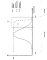
図2は、本発明の第1の実施形態において、照明ユニット10から照射される光の特性を示すグラフである。
FIG. 2 is a graph showing the characteristics of the light emitted from the
図2における中央の山なりの太線は、人間の目で見える典型的な波長域を示す。図2によれば、人間の目で見える典型的な波長域は、好ましくは、380nmから780nmの範囲に亘る。この380nmから780nmの波長域は、可視光領域(visible range)として知られている。780nmよりも上の領域(長い波長域)は、通常、赤外線範囲と呼ばれる。 The thick line at the center of the mountain in FIG. 2 indicates a typical wavelength range visible to human eyes. According to FIG. 2, a typical wavelength range visible to the human eye preferably ranges from 380 nm to 780 nm. This wavelength range of 380 nm to 780 nm is known as the visible light range. The region above 780 nm (long wavelength region) is usually referred to as the infrared range.
図2は更に、人間の目の感度の高域側領域(上限領域)(upper border area)13を示す。好適な実施形態では、この高域側領域13は、約680nmから約780nmの波長範囲である。
FIG. 2 further shows the upper band area (upper border area) 13 of the sensitivity of the human eye. In the preferred embodiment, the
図2は更に、図1の赤外線カットフィルタ5の特性を一点鎖線で示す。この実施形態における赤外線カットフィルタ5は、380nmから約730nmの波長域ではほぼ100%赤外線を透過させるが、それ以外の波長域では、図2に示すように実質的に赤外線を透過させない。
FIG. 2 further shows the characteristic of the
図2は更に、照明ユニット10から照射される光12を示す。この実施形態では、光12は、完全に人間の目の感度の高域側領域13内にあり、赤外線カットフィルタ5の遮断限界よりも完全に下の領域にある。この第1の実施形態では、赤外線カットフィルタ5の遮断限界は、人間の目の感度の高域側領域13内にある。
FIG. 2 further shows the light 12 emitted from the
図3は、本発明の第2の実施形態において、照明ユニット10から照射される光の特性を示すグラフである。
FIG. 3 is a graph showing the characteristics of the light emitted from the
図2に示した第1の実施形態と対比すると、図3の第2の実施形態において、照明ユニット10から照射される光12は、部分的に、人間の目の感度の高域側領域 (upper region)13内にあると共に、赤外線カットフィルタ5の遮断限界よりも完全に下にある。第2の実施形態では特に、照明ユニット10は、その50%が人間の目の感度の高域側領域13内となる光12により、図1の被写体7を照らす。
In contrast to the first embodiment shown in FIG. 2, in the second embodiment of FIG. 3, the light 12 emitted from the
図4は、本発明の第3の実施形態において、照明ユニット10から照射される光の特性を示すグラフである。
FIG. 4 is a graph showing the characteristics of the light emitted from the
第3の実施形態では、波長が、完全に人間の目の感度の高域側領域3内であると共に、赤外線カットフィルタ5の遮断限界よりも部分的に下の領域の波長(短い波長)を含む光12により、図1に示す被写体7は照らされる。
In the third embodiment, the wavelength is completely within the high-pass region 3 of the sensitivity of the human eye, and the wavelength (short wavelength) in the region partially below the cutoff limit of the
図5は、第4の実施形態において、照明ユニット10から照射される光の特性を示すグラフである。
FIG. 5 is a graph showing the characteristics of the light emitted from the
図2に示した実施形態と同様に、完全に人間の目の感度の高域側領域13内であると共に、赤外線カットフィルタ5の遮断限界よりも完全に下の領域の波長(短い波長)の光12により、図1に示す被写体7は照らされる。第4の実施形態では、赤外線カットフィルタ5は、図5の一点鎖線に示すように、可視光領域(380nm〜780nm)の赤外光を完全に通す特性である。従って、赤外線カットフィルタ5は、その遮断限界が赤外光の範囲内となる。即ち、図2〜図4に示した第1〜第3の実施形態とは対照的に、第4の実施形態の赤外線カットフィルタ5は、その遮断限界の波長が人間の目の感度の高域側領域13の外側となる。
Similar to the embodiment shown in FIG. 2, the wavelength (short wavelength) of the region completely below the cutoff limit of the
図1に示す被写体7を照らすために照明ユニット10から照射される光の特性について、図2〜図5にそれぞれ対応する複数の異なる実施形態を説明したが、全ての実施形態は、人間の目では殆ど周囲を識別できない暗い状況下でもカメラシステム1が当該周囲を画像化できる点で共通である。これは、イメージセンサ4が照明ユニット10の照射光の範囲において優れた感度を有するため、暗い状況下においても周囲を描出する画像を取得可能だからである。一方、照明ユニット10は人間の目の感度の高域側領域13において機能するため、照明ユニット10からの照射光は、人間の目では殆ど感知されないので、車両内のドライバー或いは被写体となり得る車両外の人を煩わすことはない。また、赤外線カットフィルタ5が更に用いられるため、明るい状況下において、色忠実度に対する影響をかなり低くすることができる。
Although a plurality of different embodiments corresponding to FIGS. 2 to 5 have been described for the characteristics of the light emitted from the
複数の好適な実施形態を挙げながら上述のように本発明を説明してきたが、当然ながら、本発明の要旨を逸脱しない範囲で種々の省略、置き換え、変更を行うことができる。 Although the present invention has been described above by mentioning a plurality of preferred embodiments, it is of course possible to make various omissions, substitutions and changes without departing from the scope of the present invention.
本発明に係る1つのカメラシステムにおいて、例えば、複数の撮像ユニットを設けることが可能である。更に、本発明によれば、車両の外の被写体を光で照らす複数の照明ユニットを設けることもできる。また、単一の赤外線カットフィルタが設けられる実施形態を説明したが、同一の又は近い遮断限界を有する複数の赤外線カットフィルタを用いることもできる。 In one camera system according to the present invention, for example, a plurality of imaging units can be provided. Furthermore, according to the invention, it is also possible to provide a plurality of lighting units which illuminate the object outside the vehicle with light. Also, although embodiments have been described in which a single infrared cut filter is provided, multiple infrared cut filters having the same or near blocking limits can also be used.
1 カメラシステム
2 撮像ユニット
3 光学素子
4 イメージセンサ
5 赤外線カットフィルタ
6 筺体
7 被写体
8 演算処理ユニット
9 表示装置
10 照明ユニット
11 筺体
12 光
13 高域側(上限)領域
Reference Signs List 1 camera system 2 imaging unit 3 optical element 4
Claims (10)
前記撮像ユニット(2)により取得された前記画像データを処理することで、前記被写体(7)を表示ユニット(9)上に表示させる演算処理ユニット(8)と、
少なくとも50%が、680nmから略780nmの範囲として定義される人間の目の感度の高域側領域(13)に含まれると共に、少なくとも部分的には前記赤外線カットフィルタ(5)の遮断限界よりも下の領域の波長を有する光(12)により、前記被写体(7)を照らす少なくとも1つの照明ユニット(10)と、
を備え、
前記遮断限界より下では、前記赤外線カットフィルタ(5)は、ほぼ100%赤外線を透過させるが、前記遮断限界より上では、実質的に赤外線を透過させない、
ことを特徴とする車両用カメラシステム。 An imaging unit (2) having an image sensor (4), an optical element (3), and at least one infrared cut filter (5) and acquiring image data of a subject (7);
An arithmetic processing unit (8) for displaying the subject (7) on a display unit (9) by processing the image data acquired by the imaging unit (2);
At least 50% is included in the high side region (13) of human eye sensitivity defined as the range of 680 nm to about 780 nm , and at least partially above the cutoff limit of the infrared cut filter (5) At least one lighting unit (10), which illuminates the object (7) by light (12) having a wavelength of the lower region;
Equipped with
Below the blocking limit, the infrared cut filter (5) transmits approximately 100% infrared light, but above the blocking limit substantially does not transmit infrared light.
Camera system for a vehicle, characterized in that.
前記照明ユニット(10)は、前記人間の目の感度の高域側領域(13)に含まれると共に、前記赤外線カットフィルタ(5)の前記遮断限界よりも下の領域の波長を有する光(12)により、前記被写体(7)を照らすカメラシステム。 In the vehicle camera system according to claim 1,
The illumination unit (10) is a light (12) having a wavelength in a region lower than the cutoff limit of the infrared cut filter (5) while being included in the high region (13) of the sensitivity of the human eye A camera system that illuminates the subject (7).
前記照明ユニット(10)は、少なくとも50%が前記人間の目の感度の高域側領域(13)に含まれる光(12)により、前記被写体(7)を照らすカメラシステム。 In the vehicle camera system according to claim 1,
A camera system in which the lighting unit (10) illuminates the subject (7) with light (12) at least 50% of which is included in the high-pass region (13) of the sensitivity of the human eye.
前記照明ユニット(10)は、前記人間の目の感度の高域側領域(13)に含まれる共に、部分的には前記赤外線カットフィルタ(5)の前記遮断限界よりも下の領域の波長を有する光(12)により、前記被写体(7)を照らすカメラシステム。 In the vehicle camera system according to claim 1,
The illumination unit (10) is included in the high-pass region (13) of the sensitivity of the human eye, and partially has a wavelength of the region below the cutoff limit of the infrared cut filter (5). The camera system which illuminates the said object (7) by the light (12) which it has.
前記赤外線カットフィルタ(5)の前記遮断限界は、前記人間の目の感度の高域側領域(13)に含まれるカメラシステム。 In the vehicle camera system according to claim 1,
The camera system in which the cutoff limit of the infrared cut filter (5) is included in a high region (13) of the sensitivity of the human eye.
前記赤外線カットフィルタ(5)の前記遮断限界は、赤外光の範囲において、前記人間の目の感度の高域側領域(13)の外側にあるカメラシステム In the vehicle camera system according to claim 1,
A camera system in which the cutoff limit of the infrared cut filter (5) is outside the high region (13) of the sensitivity of the human eye in the range of infrared light
前記イメージセンサ(4)は、赤外光に感度を有するカラーイメージセンサ(IR-light sensitive color image sensor)であるカメラシステム In the vehicle camera system according to claim 1,
Camera system wherein the image sensor (4) is a color image sensor (IR-light sensitive color image sensor) having sensitivity to infrared light
前記照明ユニット(10)は、レーザ照射装置を有するカメラシステム。 In the vehicle camera system according to claim 1,
The camera system, wherein the lighting unit (10) comprises a laser irradiation device.
前記照明ユニット(10)は、1つ又は複数の発光ダイオードを有するカメラシステム。 In the vehicle camera system according to claim 1,
Camera system, wherein the lighting unit (10) comprises one or more light emitting diodes.
前記人間の目の感度の高域側領域(13)は、最短波長が680nmから始まる波長域であるカメラシステム。 In the vehicle camera system according to claim 1,
The camera system according to the present invention, wherein the high side region (13) of the sensitivity of the human eye is a wavelength range in which the shortest wavelength starts from 680 nm.
Applications Claiming Priority (2)
| Application Number | Priority Date | Filing Date | Title |
|---|---|---|---|
| DE102015005697.2A DE102015005697B4 (en) | 2015-05-04 | 2015-05-04 | Camera system for a motor vehicle |
| DE102015005697.2 | 2015-05-04 |
Publications (2)
| Publication Number | Publication Date |
|---|---|
| JP2016213818A JP2016213818A (en) | 2016-12-15 |
| JP6425681B2 true JP6425681B2 (en) | 2018-11-21 |
Family
ID=56068614
Family Applications (1)
| Application Number | Title | Priority Date | Filing Date |
|---|---|---|---|
| JP2016076327A Expired - Fee Related JP6425681B2 (en) | 2015-05-04 | 2016-04-06 | Vehicle camera system |
Country Status (5)
| Country | Link |
|---|---|
| US (1) | US10239454B2 (en) |
| EP (1) | EP3091732A1 (en) |
| JP (1) | JP6425681B2 (en) |
| KR (1) | KR101917289B1 (en) |
| DE (1) | DE102015005697B4 (en) |
Families Citing this family (2)
| Publication number | Priority date | Publication date | Assignee | Title |
|---|---|---|---|---|
| US20200097019A1 (en) * | 2018-09-26 | 2020-03-26 | GM Global Technology Operations LLC | Vision system for an automotive vehicle |
| US11409917B2 (en) | 2020-08-26 | 2022-08-09 | Red Hat, Inc. | Un-photographable screens and displays |
Family Cites Families (18)
| Publication number | Priority date | Publication date | Assignee | Title |
|---|---|---|---|---|
| JPH07128579A (en) | 1993-10-29 | 1995-05-19 | Canon Inc | Eye-gaze detecting method, eye-gaze detecting means, and video equipment having the eye-gaze detecting means |
| US20080021849A1 (en) | 1995-10-11 | 2008-01-24 | Stamps.Com Inc | System and method for printing multiple postage indicia |
| JP2002320139A (en) * | 2001-04-19 | 2002-10-31 | Matsushita Electric Ind Co Ltd | Camera device |
| DE10138361A1 (en) * | 2001-08-04 | 2003-02-27 | Daimler Chrysler Ag | Method for improving the visibility in vehicles |
| DE10335189A1 (en) * | 2003-07-30 | 2005-03-03 | Daimlerchrysler Ag | Device for improving the visibility of motor vehicles |
| CN1627317A (en) * | 2003-12-12 | 2005-06-15 | 北京阳光奥森科技有限公司 | Method for obtaining image of human faces by using active light source |
| DE102004001556A1 (en) * | 2004-01-10 | 2005-08-04 | Robert Bosch Gmbh | Night vision system for motor vehicles with partial optical filter |
| US7012551B2 (en) * | 2004-02-04 | 2006-03-14 | Ford Global Technologies, Llc | Method of anti-blinding for active night vision system |
| WO2007111317A1 (en) * | 2006-03-28 | 2007-10-04 | Kyocera Corporation | Night vision device |
| US8446470B2 (en) * | 2007-10-04 | 2013-05-21 | Magna Electronics, Inc. | Combined RGB and IR imaging sensor |
| JP2009286234A (en) * | 2008-05-28 | 2009-12-10 | Funai Electric Co Ltd | On-vehicle side view camera |
| DE102008031593A1 (en) | 2008-07-03 | 2010-01-07 | Hella Kgaa Hueck & Co. | Camera system for use in motor vehicle to assist driver during e.g. reversing vehicle, has filter system formed from red, green, blue and weight color filters, and evaluation arrangement with compensating unit to compensate infrared parts |
| KR20110140010A (en) * | 2010-06-24 | 2011-12-30 | 삼성전자주식회사 | Image sensor using near infrared signal |
| KR20120068655A (en) | 2010-12-19 | 2012-06-27 | 김인선 | Method and camera device for capturing iris or subject of good quality with one bandpass filter passing both visible ray and near infra red ray |
| KR101761921B1 (en) | 2011-02-28 | 2017-07-27 | 삼성전기주식회사 | System and method for assisting a driver |
| DE102013200427B4 (en) * | 2013-01-14 | 2021-02-04 | Robert Bosch Gmbh | Method and device for generating an all-round view image of a vehicle environment of a vehicle, method for providing at least one driver assistance function for a vehicle, all-round view system for a vehicle |
| DE102013001285A1 (en) | 2013-01-25 | 2014-07-31 | GM Global Technology Operations LLC (n. d. Ges. d. Staates Delaware) | Headlight for motor vehicle, has first light generator for generating dipped beam, where second light generator generates auxiliary light beam, which is partially propagated above half of bright-dark boundary |
| DE102013016277A1 (en) * | 2013-09-28 | 2015-04-16 | GM GLOBAL TECHNOLOGY OPERATION LLC (n. d. Ges. d. Staates Delaware) | Headlight, motor vehicle with a headlight and method for operating a headlight |
-
2015
- 2015-05-04 DE DE102015005697.2A patent/DE102015005697B4/en active Active
-
2016
- 2016-04-06 JP JP2016076327A patent/JP6425681B2/en not_active Expired - Fee Related
- 2016-04-11 EP EP16164627.8A patent/EP3091732A1/en not_active Withdrawn
- 2016-05-03 US US15/145,468 patent/US10239454B2/en active Active
- 2016-05-04 KR KR1020160055545A patent/KR101917289B1/en not_active Expired - Fee Related
Also Published As
| Publication number | Publication date |
|---|---|
| JP2016213818A (en) | 2016-12-15 |
| US20160325679A1 (en) | 2016-11-10 |
| EP3091732A1 (en) | 2016-11-09 |
| US10239454B2 (en) | 2019-03-26 |
| KR101917289B1 (en) | 2018-11-09 |
| DE102015005697A1 (en) | 2016-11-10 |
| KR20160130714A (en) | 2016-11-14 |
| DE102015005697B4 (en) | 2019-10-02 |
Similar Documents
| Publication | Publication Date | Title |
|---|---|---|
| US10671162B1 (en) | Eyeball tracking module for video glasses | |
| KR102252759B1 (en) | Display device for superimposing a virtual image on the user's field of view | |
| KR102301950B1 (en) | Data-display glasses comprising an anti-glare screen | |
| CN110320666B (en) | Display system, control device and method, computer readable medium, and moving object | |
| WO2016147486A1 (en) | Projection display device and projection display method | |
| JP2022104965A (en) | Head-up display device | |
| EP2515809A1 (en) | Signal-processing eye-protection digital spectacles | |
| JP2009278234A (en) | Display system | |
| US10520724B2 (en) | Multi-wavelength head up display systems and methods | |
| US7132654B2 (en) | Device for improving view in a vehicle | |
| KR20160062018A (en) | Data-display glasses comprising an anti-glare screen | |
| JP5179428B2 (en) | Vehicle periphery monitoring device | |
| JP6425681B2 (en) | Vehicle camera system | |
| JP7182368B2 (en) | VEHICLE DISPLAY DEVICE, METHOD AND COMPUTER PROGRAM FOR CONTROLLING VEHICLE DISPLAY DEVICE | |
| WO2019009125A1 (en) | Passenger imaging device | |
| JP2017162233A (en) | Visual line detection device and visual line detection method | |
| JP2018146761A (en) | Display device and projection device | |
| JP2008193504A (en) | Night vision device | |
| JP2019001293A (en) | On-vehicle display device | |
| JP6909911B2 (en) | Electronic devices and display methods | |
| KR102194289B1 (en) | Apparatus and Method for Inspecting Cutting-off Ability of Blue or Violet Light | |
| JP2010018121A (en) | Image monitoring device | |
| JP4834977B2 (en) | See-through type head mounted display | |
| JP2021017064A (en) | Head-up display device | |
| JP2021119065A (en) | Head-up display device |
Legal Events
| Date | Code | Title | Description |
|---|---|---|---|
| A977 | Report on retrieval |
Free format text: JAPANESE INTERMEDIATE CODE: A971007 Effective date: 20170421 |
|
| A131 | Notification of reasons for refusal |
Free format text: JAPANESE INTERMEDIATE CODE: A131 Effective date: 20170606 |
|
| A02 | Decision of refusal |
Free format text: JAPANESE INTERMEDIATE CODE: A02 Effective date: 20180327 |
|
| A521 | Request for written amendment filed |
Free format text: JAPANESE INTERMEDIATE CODE: A523 Effective date: 20180706 |
|
| A521 | Request for written amendment filed |
Free format text: JAPANESE INTERMEDIATE CODE: A821 Effective date: 20180706 |
|
| A911 | Transfer to examiner for re-examination before appeal (zenchi) |
Free format text: JAPANESE INTERMEDIATE CODE: A911 Effective date: 20180726 |
|
| TRDD | Decision of grant or rejection written | ||
| A01 | Written decision to grant a patent or to grant a registration (utility model) |
Free format text: JAPANESE INTERMEDIATE CODE: A01 Effective date: 20181002 |
|
| A61 | First payment of annual fees (during grant procedure) |
Free format text: JAPANESE INTERMEDIATE CODE: A61 Effective date: 20181023 |
|
| R150 | Certificate of patent or registration of utility model |
Ref document number: 6425681 Country of ref document: JP Free format text: JAPANESE INTERMEDIATE CODE: R150 |
|
| LAPS | Cancellation because of no payment of annual fees |