JP6336076B2 - Beverage whipping device and jug having this device - Google Patents
Beverage whipping device and jug having this device Download PDFInfo
- Publication number
- JP6336076B2 JP6336076B2 JP2016534989A JP2016534989A JP6336076B2 JP 6336076 B2 JP6336076 B2 JP 6336076B2 JP 2016534989 A JP2016534989 A JP 2016534989A JP 2016534989 A JP2016534989 A JP 2016534989A JP 6336076 B2 JP6336076 B2 JP 6336076B2
- Authority
- JP
- Japan
- Prior art keywords
- beverage
- steam
- steam inlet
- steam supply
- milk
- Prior art date
- Legal status (The legal status is an assumption and is not a legal conclusion. Google has not performed a legal analysis and makes no representation as to the accuracy of the status listed.)
- Expired - Fee Related
Links
Images




Classifications
-
- A—HUMAN NECESSITIES
- A47—FURNITURE; DOMESTIC ARTICLES OR APPLIANCES; COFFEE MILLS; SPICE MILLS; SUCTION CLEANERS IN GENERAL
- A47J—KITCHEN EQUIPMENT; COFFEE MILLS; SPICE MILLS; APPARATUS FOR MAKING BEVERAGES
- A47J31/00—Apparatus for making beverages
- A47J31/44—Parts or details or accessories of beverage-making apparatus
- A47J31/4485—Nozzles dispensing heated and foamed milk, i.e. milk is sucked from a milk container, heated and foamed inside the device, and subsequently dispensed from the nozzle
-
- A—HUMAN NECESSITIES
- A47—FURNITURE; DOMESTIC ARTICLES OR APPLIANCES; COFFEE MILLS; SPICE MILLS; SUCTION CLEANERS IN GENERAL
- A47J—KITCHEN EQUIPMENT; COFFEE MILLS; SPICE MILLS; APPARATUS FOR MAKING BEVERAGES
- A47J31/00—Apparatus for making beverages
- A47J31/44—Parts or details or accessories of beverage-making apparatus
- A47J31/4489—Steam nozzles, e.g. for introducing into a milk container to heat and foam milk
-
- A—HUMAN NECESSITIES
- A47—FURNITURE; DOMESTIC ARTICLES OR APPLIANCES; COFFEE MILLS; SPICE MILLS; SUCTION CLEANERS IN GENERAL
- A47J—KITCHEN EQUIPMENT; COFFEE MILLS; SPICE MILLS; APPARATUS FOR MAKING BEVERAGES
- A47J31/00—Apparatus for making beverages
- A47J31/44—Parts or details or accessories of beverage-making apparatus
- A47J31/60—Cleaning devices
Landscapes
- Engineering & Computer Science (AREA)
- Food Science & Technology (AREA)
- Apparatus For Making Beverages (AREA)
Description
本発明は、飲料製造装置及びその付属品に関する。より具体的には、本発明は、飲料泡立て装置、特にミルク泡立て装置及びミルク泡立て装置が設けられたジャグに関連する改良に関する。本発明は、泡立て装置を含む飲料製造マシンにさらに関する。 The present invention relates to a beverage production apparatus and its accessories. More specifically, the present invention relates to a beverage frothing device, in particular a milk frothing device and an improvement associated with a jug provided with a milk frothing device. The invention further relates to a beverage production machine comprising a whipping device.
飲料製造マシン、例えばコーヒーやエスプレッソ製造マシンには、大抵の場合、泡立てたミルク又はホットミルクを製造するための装置が設けられている。ミルク泡立て装置は、通常、ミルク吸引チャンバを含み、このチャンバには、飲料製造マシンの蒸気発生器によって生成された加圧された蒸気の流れが蒸気供給ノズルによって供給される。ミルク吸引ダクトが、ミルク容器と流体連通するとともに、ミルク吸引チャンバと流体連通する。ミルク吸引チャンバを通って流れる加圧された高温蒸気の流れは、ベンチュリ効果によって、ミルク吸引チャンバ内に負圧を発生させ、それによってミルクが、ミルク吸引ダクトを通して吸引され、蒸気と混合され且つ蒸気に含まれる気化潜熱によって加熱され、蒸気は、ミルクの流れで凝縮される。ミルク吸引チャンバと流体連通する吸気ポートが、さらに設けられており、必要に応じて、調整可能な量の空気を、ミルク経路内に吸引することができる。こうして、ミルクを空気で乳化して泡立てたミルクを製造することができる。吸気ポートの断面積を調整し、こうして泡の量を調整する調整可能なピンが、通常、設けられる。吸気ポートがこのピンによって完全に閉鎖される場合に、空気は、ミルク経路内に全く吸引されず、泡立てないホットミルクが生成される。この種の泡立て装置が、例えば特許文献1に開示されている。 Beverage production machines, such as coffee and espresso production machines, are often provided with devices for producing frothed milk or hot milk. A milk frothing device typically includes a milk suction chamber, which is supplied with a stream of pressurized steam generated by a steam generator of a beverage production machine by a steam supply nozzle. A milk suction duct is in fluid communication with the milk container and in fluid communication with the milk suction chamber. The flow of pressurized hot steam flowing through the milk suction chamber creates a negative pressure in the milk suction chamber due to the Venturi effect, whereby milk is sucked through the milk suction duct, mixed with the steam and steam The steam is condensed by the flow of milk. An intake port in fluid communication with the milk suction chamber is further provided so that an adjustable amount of air can be sucked into the milk path as required. Thus, milk can be produced by emulsifying the milk with air. Adjustable pins are usually provided to adjust the cross-sectional area of the intake port and thus adjust the amount of foam. When the intake port is completely closed by this pin, no air is sucked into the milk path, producing hot milk that does not foam. This type of foaming device is disclosed in Patent Document 1, for example.
この種のミルク泡立て装置は、使用中に効率的であり且つ柔軟性を有するが、吸気ポートの狭い断面積によって主に生じる同じ欠点に悩まされる。これは、例えば吸気ポートに入るミルクによって、大抵の場合、吸気ポートの詰まりのリスクを生じさせる。 This type of milk frothing device is efficient and flexible in use, but suffers from the same drawbacks mainly caused by the narrow cross-sectional area of the intake port. This creates a risk of clogging of the intake port, in most cases, for example by milk entering the intake port.
これらの問題を克服するために、特許文献2は、新規な泡立て装置を開示しており、この装置では、大きな空気通路又は吸気ポートが、ミルク経路に沿って配置される。吸気ポートは、実際に、ミルクが流れる連続して配置された2つのパイプ同士の間の空間によって形成される。多量の空気が、ミルクの流れに取り込まれ且つミルクと混合され、ミルクの泡を生成する。泡立てたミルクから過剰な空気を除去するために、サイクロンチャンバが、吸気ポートの下流側に配置される。この既知の装置は、吸気ポートの詰まりの問題を解決する。しかしながら、この公知の装置は、空気調整ピンが設けられた他の泡立て装置の使用に同様の柔軟性を提供しない。空気調整ピンの欠如によって、この装置は、泡立てないホットミルクの製造に適していない。 In order to overcome these problems, U.S. Patent No. 6,053,077 discloses a new frothing device in which large air passages or intake ports are arranged along the milk path. The intake port is actually formed by the space between two consecutively arranged pipes through which milk flows. A large amount of air is taken into the milk stream and mixed with the milk, producing a milk foam. A cyclone chamber is located downstream of the intake port to remove excess air from the frothed milk. This known device solves the problem of clogged intake ports. However, this known device does not provide the same flexibility for the use of other whipping devices provided with air conditioning pins. Due to the lack of air conditioning pins, this device is not suitable for the production of non-foamed hot milk.
第1の態様によれば、本発明は、第1の飲料通路を含む飲料泡立て装置に関し、第1の飲料通路は、第1の飲料吸引ダクト及び第1の蒸気入口ダクトと流体連通する第1の飲料吸引チャンバであって、第1の蒸気入口ダクトを通って流れる蒸気によって、第1の飲料吸引ダクトを通る飲料の吸引を生じさせ、第1の飲料吸引ダクトは、飲料容器と流体連通を確立するように構成される、第1の飲料吸引チャンバと;吸気ポートと;第1の飲料吸引ダクトを通して供給される飲料を吸気ポートからの空気と混合して、泡立てた飲料を製造するための泡立て装置と;泡立てた飲料が分配される第1の飲料分配注ぎ口と;から構成される。この装置は、第2の飲料通路をさらに含み、第2の飲料通路は、第2の飲料吸引ダクト及び第2の蒸気入口ダクトと流体連通する第2の飲料吸引チャンバであって、第2の蒸気入口ダクトを通って流れる蒸気によって、第2の飲料吸引ダクトを通る飲料の吸引を生じさせ、第2の飲料吸引ダクトは、飲料容器と流体連通するように構成される、第2の飲料吸引チャンバから構成される。さらに、この装置は、蒸気供給源から蒸気を受け取り、泡立てたホット(hot)飲料を製造するために第1の蒸気入口ダクトに又は泡立てないホット飲料を製造するために第2の蒸気入口ダクトに選択的に蒸気を供給するように構成された少なくとも1つの蒸気供給装置を有する。この目的のために、蒸気供給装置には、第1の位置と第2位置との間で切り替えることができる切替部材が配置され、第1の位置では、蒸気入口開孔部から(第2の蒸気入口ダクト内ではなく)第1の蒸気入口ダクト内に蒸気を供給する;第2の位置では、蒸気入口開孔部から(第1の蒸気入口ダクト内ではなく)第2の蒸気入口ダクト内に蒸気を供給する。切替部材は、洗浄目的のために、蒸気入口開孔部と第1及び第2の蒸気入口ダクトの両方との間に流体接続が確立されるような第3の切替位置をさらに有する。 According to a first aspect, the present invention relates to a beverage whipping device including a first beverage passage, the first beverage passage being in fluid communication with a first beverage suction duct and a first steam inlet duct. A beverage suction chamber, wherein the steam flowing through the first steam inlet duct causes a suction of the beverage through the first beverage suction duct, the first beverage suction duct being in fluid communication with the beverage container. A first beverage suction chamber configured to establish; an intake port; and the beverage supplied through the first beverage suction duct is mixed with air from the intake port to produce a whipped beverage A whipping device; and a first beverage dispensing spout from which the whipped beverage is dispensed. The apparatus further includes a second beverage passage, wherein the second beverage passage is a second beverage suction chamber in fluid communication with the second beverage suction duct and the second steam inlet duct, Steam that flows through the steam inlet duct causes a suction of the beverage through the second beverage suction duct, the second beverage suction duct configured to be in fluid communication with the beverage container. Consists of a chamber. In addition, the apparatus receives steam from a steam source and in a first steam inlet duct to produce a whipped hot beverage or in a second steam inlet duct to produce a non-whipped hot beverage. Having at least one steam supply configured to selectively supply steam; For this purpose, the steam supply device is provided with a switching member that can be switched between a first position and a second position, and in the first position from the steam inlet opening (second Steam is fed into the first steam inlet duct (not in the steam inlet duct); in the second position, from the steam inlet opening (inside the first steam inlet duct) into the second steam inlet duct To supply steam. The switching member further has a third switching position such that a fluid connection is established between the steam inlet opening and both the first and second steam inlet ducts for cleaning purposes.
以下の説明から明らかになるように、蒸気供給装置は、1つ又は複数の蒸気供給ノズルを含むことができる。
泡立て装置は、飲料を空気と混合して泡立てた飲料を形成するような泡立てチャンバを構成することができる。例えば、泡立て装置は、吸気チャンバを含むことができ、その吸気チャンバに空気を吸引し、吸気チャンバに入る飲料と密に混合させる。いくつかの実施形態によれば、飲料は、吸気チャンバに入る前に、加圧された高温蒸気と接触させることができ、それにより飲料は、最初に加熱され、続いて吸気チャンバ内の空気と混合することにより泡立てられる。他の実施形態では、空気及び飲料を混合して泡立てた飲料を得て、その後、高温蒸気と混合することによって加熱することができる。さらに別の実施形態では、空気、蒸気、及び飲料は、飲料を加熱及び同時に泡立てるためにこれら3つの流れを一緒に混合するように単一の泡立てチャンバに入ることができる。
As will become apparent from the description below, the steam supply device may include one or more steam supply nozzles.
The whipping device can constitute a whipping chamber that mixes the beverage with air to form a whipped beverage. For example, the whipping device can include an intake chamber that draws air into the intake chamber and intimately mixes with the beverage entering the intake chamber. According to some embodiments, the beverage can be contacted with pressurized hot steam prior to entering the intake chamber, whereby the beverage is first heated, followed by air in the intake chamber. Foamed by mixing. In other embodiments, air and beverage can be mixed to obtain a whipped beverage and then heated by mixing with hot steam. In yet another embodiment, air, steam, and beverage can enter a single whipping chamber to mix these three streams together to heat and whipping the beverage at the same time.
特にコンパクトで効率的ないくつかの実施形態によれば、蒸気供給装置は、少なくとも第1の位置及び第2の位置で選択的に移動可能な少なくとも1つの蒸気供給ノズルを有し、蒸気供給ノズルは、蒸気供給源からの蒸気を受け取るように適合される。第1の位置では、蒸気供給ノズルは、泡立てた飲料を製造するために、第2の蒸気入口ダクトではなく、第1の蒸気入口ダクトと流体連通する。第2の位置では、蒸気供給ノズルは、泡立てないホット飲料を製造するために、第1の蒸気入口ダクトではなく、第2の蒸気入口ダクトと流体連通する。 According to some particularly compact and efficient embodiments, the steam supply device has at least one steam supply nozzle that is selectively movable in at least a first position and a second position, and the steam supply nozzle Is adapted to receive steam from a steam source. In the first position, the steam supply nozzle is in fluid communication with the first steam inlet duct instead of the second steam inlet duct to produce a whipped beverage. In the second position, the steam supply nozzle is in fluid communication with the second steam inlet duct rather than the first steam inlet duct to produce a non-foamed hot beverage.
こうして、泡立て装置は、空気入口開孔部を閉じるバルブ又はシャッターを必要とせず、泡立てたホット飲料、又は泡立てないホット飲料を交互に分配することができる。こうして、空気入口開孔部は、飲料残渣の蓄積による詰まりを防止するために比較的大きな断面積を有するように設計することができる。当技術分野で公知のように、第1の飲料分配注ぎ口は、泡立てた飲料の流れから過剰な空気を除去するために、サイクロン又は同等物として設計することができる。
いくつかの実施形態では、泡立てない飲料は、泡立てた飲料が分配される同じ第1の飲料分配注ぎ口から分配することができる。
Thus, the whipping device does not require a valve or shutter to close the air inlet opening, and can alternately dispense whipped hot beverage or non-foamed hot beverage. Thus, the air inlet aperture can be designed to have a relatively large cross-sectional area to prevent clogging due to beverage residue accumulation. As is known in the art, the first beverage dispensing spout can be designed as a cyclone or equivalent to remove excess air from the whipped beverage stream.
In some embodiments, the non-whipped beverage can be dispensed from the same first beverage dispensing spout where the whipped beverage is dispensed.
好ましい実施形態によれば、第2の飲料通路は、泡立てないミルクが分配される第2の飲料分配注ぎ口を含む。第1の飲料分配注ぎ口及び第2の飲料分配注ぎ口は、泡立てた飲料を製造する場合に、例えば第1の飲料分配注ぎ口によって提供されるサイクロン効果によって、泡立てた飲料が、第2の飲料分配注ぎ口に入るのを防止するように設計することができる。例えば、第2の飲料分配注ぎ口の出口開孔部は、第1の飲料分配注ぎ口を通して分配される泡立てた飲料が第2の飲料分配注ぎ口に入るのを防止する、隔壁又は他の任意の適切な構成によって保護することができる。いくつかの実施形態では、第1の飲料分配注ぎ口及び第2の飲料分配注ぎ口は、下向きに向き合わせされた両方の出口開孔部と並べて配置することができる。 According to a preferred embodiment, the second beverage passage comprises a second beverage dispensing spout where non-foamed milk is dispensed. The first beverage dispensing spout and the second beverage dispensing spout are used when producing a whipped beverage, for example, by the cyclone effect provided by the first beverage dispensing spout, It can be designed to prevent entry into the beverage dispensing spout. For example, the outlet opening of the second beverage dispensing spout can be a septum or other optional device that prevents whipped beverage dispensed through the first beverage dispensing spout from entering the second beverage dispensing spout Can be protected by an appropriate configuration. In some embodiments, the first beverage dispensing spout and the second beverage dispensing spout can be placed side by side with both outlet apertures facing downward.
いくつかの実施形態によれば、蒸気供給ノズルは、移動可能な切替部材に配置することができ、それによって切替部材を対応する切替位置に移動させることによって、蒸気供給ノズルを、その様々な位置に選択的に移動させることができる。切替部材は、様々な選択切替位置のうちのいずれかの位置となるように回転軸線を中心に回転可能である。他の実施形態によれば、切替部材は、回転運動ではなく、並進運動に従って移動することができる。例えば、切替部材が、スライド上に配置されるか、又はスライドにより形成される。しかしながら、泡立て装置のよりコンパクトな構造をもたらすので、回転式切替部材が、好ましい。また、回転式切替部材は、組み立てが容易であり、より信頼性が高く且つ堅牢である。いくつかの実施形態では、切替部材の回転軸線は、蒸気供給ノズルに直交する。いくつかの実施形態では、切替部材は、蒸気供給源と、一方の、他方の、又は両方の蒸気入口ダクトと選択的に流体連通するように配置された2つ以上の蒸気供給ノズルを含むことができる。 According to some embodiments, the steam supply nozzle can be disposed on a movable switching member, thereby moving the switching member to a corresponding switching position, thereby moving the steam supply nozzle to its various positions. Can be moved selectively. The switching member is rotatable about the rotation axis so as to be in any one of various selection switching positions. According to another embodiment, the switching member can move according to a translational motion rather than a rotational motion. For example, the switching member is disposed on the slide or formed by the slide. However, a rotary switching member is preferred because it provides a more compact structure of the whipping device. Further, the rotary switching member is easy to assemble, is more reliable, and is robust. In some embodiments, the axis of rotation of the switching member is orthogonal to the steam supply nozzle. In some embodiments, the switching member includes two or more steam supply nozzles disposed in selective fluid communication with the steam supply source and one, the other, or both steam inlet ducts. Can do.
特に有利な実施形態によれば、切替部材は、蒸気が第1の蒸気入口ダクトに供給されたときに、第1の飲料吸引ダクトと、及び蒸気が第2の蒸気入口ダクトに供給されたときに、第2の飲料吸引ダクトと、の流体連通が選択的にもたらされる飲料供給ダクトをさらに含む。例えば切替部材の回転軸線と同軸に配置された可撓性パイプを設けることができ、この可撓性パイプは、飲料容器の内側に延び、その飲料容器から飲料を吸引する。この配置によって、2つの飲料通路のどちらか一方と選択的に流体連通するように配置され単一の飲料吸引パイプ又はダクトを設けることができる。選択は、切替部材に作用を与えることによって得られる。 According to a particularly advantageous embodiment, the switching member is arranged when the steam is supplied to the first steam inlet duct, the first beverage suction duct, and when the steam is supplied to the second steam inlet duct. And a beverage supply duct that is selectively provided in fluid communication with the second beverage suction duct. For example, a flexible pipe arranged coaxially with the rotation axis of the switching member can be provided, the flexible pipe extending inside the beverage container and sucking the beverage from the beverage container. With this arrangement, a single beverage suction pipe or duct can be provided that is arranged in selective fluid communication with either one of the two beverage passages. The selection is obtained by acting on the switching member.
1つ又は複数の更に可能な実施形態によれば、第1の飲料通路及び第2の飲料通路と流体連通する2つの別々の飲料供給ダクトを設けることができる。飲料は、加圧蒸気がどちらの通路に供給されるかに応じて、2つの飲料供給ダクトのうちのどちらか一方によって吸引される。
いくつかの実施形態では、切替部材は、第3の、洗浄位置を有する。
切替部材は、蒸気供給源と、第1及び第2の飲料通路の第1及び第2の蒸気入口ダクトとの間の流れ接続を確立するように構成された、追加の蒸気又は熱水供給ノズルを含むことができる。こうして、追加の蒸気又は熱水供給ノズルを介して供給される蒸気又は熱水は、2つの飲料通路を洗浄又は清掃するために使用される。
According to one or more further possible embodiments, two separate beverage supply ducts can be provided in fluid communication with the first beverage passage and the second beverage passage. Beverages are aspirated by either one of the two beverage supply ducts depending on which passage the pressurized steam is supplied to.
In some embodiments, the switching member has a third, cleaning position.
The switching member is an additional steam or hot water supply nozzle configured to establish a flow connection between the steam source and the first and second steam inlet ducts of the first and second beverage passages. Can be included. Thus, steam or hot water supplied via an additional steam or hot water supply nozzle is used to wash or clean the two beverage passages.
他の実施形態によれば、全く同一の蒸気供給ノズルが、泡立てたホット飲料又は泡立てないホット飲料を交互に製造するように第1又は第2の飲料通路との接続を選択的に確立するために、又は洗浄又は清掃目的のために蒸気供給源と第1及び第2の飲料通路の両方との間の同時接続を確立するために使用される。この第3の可能な位置では、蒸気又は熱水は、飲料、例えばミルクと接触するその装置の構成要素を洗浄するためにこの装置を通して供給することができる。 According to another embodiment, the identical steam supply nozzle selectively establishes a connection with the first or second beverage passage so as to alternately produce whipped hot beverage or non-whipped hot beverage. Or for establishing a simultaneous connection between the steam source and both the first and second beverage passages for cleaning or cleaning purposes. In this third possible position, steam or hot water can be supplied through this device to clean the components of the device that come into contact with the beverage, eg milk.
いくつかの実施形態では、蒸気供給ノズルには、第1の端部開口部及び第2端開口部を設けることができる。第1の端部開口部は、切替部材と一体的に移動可能である蒸気分配チャンバと流体連通し及び切替部材の移動方向の寸法を有し、それによって第1の切替位置及び第2の切替位置の両方において、蒸気分配チャンバは、蒸気入口開孔部と、第1の蒸気入口ダクト又は第2の蒸気入口ダクトとの間で流れ接続を選択的に確立するために、蒸気入口開孔部と流体連通する。蒸気供給ノズルの第2の端部開口部は、切替部材の位置に応じて、第1の蒸気入口ダクト及び第2の蒸気入口ダクトのいずれか一方のみと流体接続を選択的に確立するために、十分に小さい断面積を有する。この配置によって、切替部材をシフトすることによって、切替部材が第3の、洗浄又は清掃位置にあるときに、2つの飲料通路を通じて同時に蒸気又は水を流すことができる。さらに、切替部材が第1及び第2の飲料製造位置のどちらか一方に配置されたときに、第1又は第2の飲料通路を通して蒸気を選択的に流すことができる。 In some embodiments, the steam supply nozzle can be provided with a first end opening and a second end opening. The first end opening is in fluid communication with the vapor distribution chamber that is movable integrally with the switching member and has a dimension in the direction of movement of the switching member, whereby the first switching position and the second switching position. In both locations, the steam distribution chamber has a steam inlet aperture to selectively establish a flow connection between the steam inlet aperture and the first steam inlet duct or the second steam inlet duct. In fluid communication. The second end opening of the steam supply nozzle is configured to selectively establish a fluid connection with only one of the first steam inlet duct and the second steam inlet duct, depending on the position of the switching member. Have a sufficiently small cross-sectional area. This arrangement allows the steam or water to flow simultaneously through the two beverage passages when the switching member is in the third, cleaning or cleaning position by shifting the switching member. Furthermore, steam can be selectively flowed through the first or second beverage passage when the switching member is disposed in one of the first and second beverage production positions.
上述したように、他の実施形態では、切替部材には、複数の蒸気供給ノズル、例えば一方の、他方の、両方の飲料通路とのいずれかと及び蒸気入口開孔部とを選択的に流体連通するように配置された2つの蒸気供給ノズルを設けることができる。例えば、切替部材には、第1の蒸気供給ノズルが蒸気入口開孔部と2つの飲料通路のうちの第1の通路との間の接続を確立する第1の切替位置から、第2の蒸気供給ノズルが蒸気入口開孔部と2つの飲料通路のうちの第2の通路との間の接続を確立する第2の切替位置に、並進運動を提供することができる。切替部材が第3の、洗浄位置にあるときに、蒸気入口開孔部と両方の飲料通路との間の同時接続を確立するために、第3の蒸気供給ノズルを設けることができる。 As described above, in other embodiments, the switching member is selectively in fluid communication with a plurality of steam supply nozzles, eg, one of the other, both beverage passages, and the steam inlet aperture. There may be provided two steam supply nozzles arranged to do so. For example, the first steam supply nozzle is connected to the switching member from the first switching position where the first steam supply nozzle establishes a connection between the steam inlet opening and the first of the two beverage paths. Translational motion can be provided to a second switching position where the supply nozzle establishes a connection between the steam inlet aperture and the second of the two beverage passages. A third steam supply nozzle can be provided to establish a simultaneous connection between the steam inlet aperture and both beverage passages when the switching member is in the third, wash position.
切替部材の移動は、手動で又はアクチュエータによって制御することができる。
いくつかの実施形態では、切替部材は、泡立て装置が取り付け又は相互接続される飲料製造マシンに設けられた感知装置に作用を与えることができる。こうして、飲料製造マシンは、ユーザが切替部材を移動した位置を検出することができる。例えば、飲料製造マシンには、その位置を検出するために、切替部材と共に機能する静電容量センサ、マイクロスイッチ又は他の感知装置を設けることができる。
The movement of the switching member can be controlled manually or by an actuator.
In some embodiments, the switching member can act on a sensing device provided in a beverage production machine to which the whipping device is attached or interconnected. Thus, the beverage manufacturing machine can detect the position where the user has moved the switching member. For example, a beverage production machine can be provided with a capacitive sensor, microswitch or other sensing device that works with the switching member to detect its position.
感知した位置に基づいて、正しいサイクルを行うように飲料製造マシンを制御することができる。例えば飲料製造マシンがコーヒーマシンである場合であって、蒸気供給ノズルが第2の飲料通路と流体連通しているときに、切替部材によって、コーヒーマシンをホットミルク製造モードに切り替えることができる。あるいはまた、蒸気供給ノズルが第1の飲料通路と接続を確立するときに、切替部材によって、コーヒーマシンをカプチーノ製造モードに切り替えることができる。切替部材が第3の、洗浄位置にある場合に、コーヒー製造マシンは、切替部材が第3の位置に配置されたとき、洗浄モードに自動的に切り替えることができる。 Based on the sensed position, the beverage production machine can be controlled to perform the correct cycle. For example, when the beverage production machine is a coffee machine and the steam supply nozzle is in fluid communication with the second beverage passage, the switching member can switch the coffee machine to the hot milk production mode. Alternatively, the coffee machine can be switched to cappuccino production mode by the switching member when the steam supply nozzle establishes a connection with the first beverage passage. When the switching member is in the third, cleaning position, the coffee making machine can automatically switch to the cleaning mode when the switching member is placed in the third position.
いくつかの実施形態では、洗浄は、蒸気又は熱水、あるいはその両方を飲料通路を通して供給することにより行うことができる。
いくつかの実施形態では、切替部材は、切替部材が第3の、洗浄位置にあるときに、第1の飲料吸引ダクト及び第2の飲料吸引ダクトが切替部材と一体的に移動可能なシャッターによって閉鎖されるように構成することができる。他の実施形態では、別個のシャッターによって、第1及び第2の飲料吸引ダクトを閉鎖する。
In some embodiments, cleaning can be accomplished by supplying steam or hot water, or both, through the beverage passage.
In some embodiments, the switching member is a shutter that allows the first beverage suction duct and the second beverage suction duct to move integrally with the switching member when the switching member is in the third, cleaning position. It can be configured to be closed. In other embodiments, separate shutters close the first and second beverage suction ducts.
一般的に、泡立て装置は、飲料製造マシン、例えばコーヒーマシン用の追加部品、又はそのようなマシンの内部部品として設計することができる。加熱又は泡立てるための飲料を容器から吸引できるこのケースでは、マシンには、飲料パッケージ、例えばミルクパックが設けられる、又はこのパックから直接的に供給される。
現在好ましいと考えられる他の実施形態では、飲料泡立て装置は、飲料ジャグに一体化することができる。例えば、泡立て装置は、ジャグのカバー内に収容することができ、又はジャグのカバーによって支持される。
In general, the whipping device can be designed as an additional part for a beverage production machine, for example a coffee machine, or as an internal part of such a machine. In this case where the beverage for heating or whipping can be sucked out of the container, the machine is provided with or directly supplied with a beverage package, for example a milk pack.
In other embodiments presently preferred, the beverage whipping device can be integrated into the beverage jug. For example, the frothing device can be housed in or supported by a jug cover.
更なる態様によれば、本発明は、蒸気供給ラインと飲料泡立て装置の蒸気供給ノズルとの間に流体連通を確立するために、上述したような蒸気供給ライン及びこの蒸気供給ラインに接続可能である飲料泡立て装置を有する飲料製造マシンに関する。
本発明の更なる特徴及び利点は、その例示的な実施形態の以下の詳細な説明、及び本明細書の不可欠な部分を形成する添付の特許請求の範囲に記載される。
According to a further aspect, the present invention is connectable to a steam supply line as described above and to this steam supply line in order to establish fluid communication between the steam supply line and the steam supply nozzle of the beverage frothing device. The present invention relates to a beverage production machine having a certain beverage whipping device.
Additional features and advantages of the invention are set forth in the following detailed description of exemplary embodiments thereof, and in the appended claims forming an integral part of the specification.
本発明のより完全な理解及び直ぐに同様に取得されるであろうその多くの利点は、本発明の非限定的な例示的な一実施形態を示す添付図面と一緒に考慮するときに、以下の詳細な説明を参照することによってより良く理解される。
例示的な実施形態についての以下の詳細な説明では、添付図面を参照する。異なる図面における同じ参照符号は、同一又は同様の要素を特定する。さらに、図面は、必ずしも一定の縮尺で描かれていない。また、以下の詳細な説明は、本発明を限定するものではない。代わりに、本発明の範囲は、添付の特許請求の範囲によって規定される。
A more complete understanding of the present invention and its many advantages that will soon be obtained as well, when considered in conjunction with the accompanying drawings showing a non-limiting exemplary embodiment of the present invention, include: A better understanding can be obtained by reference to the detailed description.
In the following detailed description of the exemplary embodiments, reference is made to the accompanying drawings. The same reference numbers in different drawings identify the same or similar elements. Further, the drawings are not necessarily drawn to scale. Also, the following detailed description does not limit the invention. Instead, the scope of the invention is defined by the appended claims.
明細書を通して、「一実施形態」、「実施形態」、又は「いくつかの実施形態」の言及は、ある実施形態に関連して説明した特定の特徴、構造又は特性が、開示される主題の少なくとも1つの実施形態に含まれることを意味する。従って、明細書を通して様々な箇所での「一実施形態では」、「実施形態では」、又は「いくつかの実施形態では」という語句の出現は、必ずしも同じ実施形態(複数可)を参照するものではない。さらに、特定の特徴、構造、又は特性は、1つ又は複数の実施形態において任意の適切な方法で組み合わせることができる。 Throughout the specification, references to “one embodiment,” “embodiment,” or “some embodiments” refer to particular features, structures, or characteristics described in connection with an embodiment of the disclosed subject matter. It is meant to be included in at least one embodiment. Thus, appearances of the phrases “in one embodiment”, “in an embodiment”, or “in some embodiments” in various places throughout the specification are not necessarily referring to the same embodiment (s). is not. Furthermore, the particular features, structures, or characteristics may be combined in any suitable manner in one or more embodiments.
以下の本明細書中で、特にミルク泡立て装置について参照を行う。
このような装置は、ミルクジャグやコーヒーマシンと有用に組み合わせることができる。しかしながら、泡立て装置及びその機構は、空気と混合して泡立てることができる及び/又は飲料を高温蒸気の流れと接触させることによって加熱することができる様々な飲料、すなわち、あらゆる食品液体又は実質的な液体製品を泡立てるためにも使用できることを理解しなければならない。
In the following description, reference is made in particular to the milk frothing device.
Such devices can be usefully combined with milk jugs and coffee machines. However, the whipping device and its mechanism can be mixed with air and / or various beverages that can be heated by contacting the beverage with a stream of hot steam, ie any food liquid or substantially It must be understood that it can also be used to foam liquid products.
本明細書に開示された実施形態では、ミルク泡立て装置は、ミルクジャグ(jug)と組み合わされ、より具体的にはミルクジャグのカバー内に配置される。他の実施形態では、図示しないが、ミルク泡立て装置は、一方で飲料製造マシンに及び他方で別のミルク容器に直接的に振り分けられる別個の構成要素の形態とすることができる。
また、以下の詳細な説明では、手動切替システムを含み、いくつかの動作位置の間で切り替えることができるミルク泡立て装置について参照を行う。他の実施形態では、図示しないが、泡立て装置の位置を選択するためにアクチュエータを設けることができる。
In the embodiments disclosed herein, the milk frothing device is combined with a milk jug and more specifically placed within the cover of the milk jug. In other embodiments, although not shown, the milk frothing device can be in the form of a separate component that is directly distributed on the one hand to the beverage production machine and on the other hand to another milk container.
Also, in the following detailed description, reference is made to a milk frothing device that includes a manual switching system and can be switched between several operating positions. In other embodiments, although not shown, an actuator can be provided to select the position of the foaming device.
図1は、本発明に係るミルク泡立て装置を含むミルクジャグ1の側面図を示す。この実施形態では、ミルクジャグ1は、ジャグ本体3と、ジャグカバー5とを有する。ジャグカバー5は、蒸気供給ラインが設けられた飲料製造マシン、例えばコーヒーマシンやエスプレッソマシン(図示せず)にジャグを接続するための蒸気コネクタを形成する突起部7を有することができる。蒸気コネクタは、ジャグカバー5内に配置された後で詳細に説明する蒸気回路に流体接続される。図12に示されるように、ミルクジャグ1は、飲料製造マシン2、例えばコーヒー製造マシンに接続することができる。飲料製造マシン2には、蒸気供給ライン4を設けることができる。
FIG. 1 shows a side view of a milk jug 1 including a milk frothing device according to the present invention. In this embodiment, the milk jug 1 has a
突起部7の反対側で、ジャグ1には、泡立てた又は泡立てないホットミルクが分配されるノーズ9を設けることができる。いくつかの実施形態によれば、図示しないが、ノーズ9又は突起部7は、必要に応じてそれらノーズ又は突起部を向き合わせするように、例えばマシン2のコーヒー分配ノズルの下に置かれたカップの上にノーズ9を配置するために、ジャグに回動可能に取り付けることができる。さらに別の実施形態では、ノーズ9及び突起部7は、180°とは異なる角度で、例えば90°又は120°で向き合わせすることができる。
On the opposite side of the protrusion 7, the jug 1 can be provided with a nose 9 in which hot or non-foamed hot milk is dispensed. According to some embodiments, although not shown, the nose 9 or protrusion 7 was placed, for example, under the coffee dispensing nozzle of the
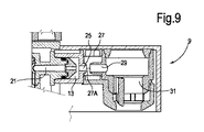
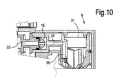
ここで図2、図3及び図8〜図11を参照し、ジャグカバー5内に収容された泡立て装置11の主な機構について説明する。
いくつかの実施形態では、ミルク泡立て装置11は、第1のミルク吸引チャンバ13と、第2のミルク吸引チャンバ15とを有する。第1のミルク吸引チャンバ13は、第1のミルク吸引ダクト17と流体連通する。第2のミルク吸引チャンバ15は、第2のミルク吸引ダクト19と流体連通する。
Here, the main mechanism of the foaming device 11 accommodated in the
In some embodiments, the milk frothing device 11 has a first
さらに、第1のミルク吸引チャンバ13は、第1の蒸気入口ダクト21に接続され、第2のミルク吸引チャンバ15は、第2の蒸気入口ダクト23に接続される。以下でより詳細に説明するように、蒸気は、第1の蒸気入口ダクト21及び第2の蒸気入口ダクト23のどちらか一方を通して選択的に供給することができる。切替装置が、蒸気の流れを同様に切り替えるために設けられる。第1の蒸気入口ダクト21又は第2の蒸気入口ダクト23を通って流れる加圧蒸気は、ベンチュリ効果により、第1又は第2のミルク吸引チャンバ13、15それぞれにミルクの吸引を生じさせる。
Further, the first
図面に示される例示的な実施形態では、2つのミルク吸引ダクト17、19は、実質的に同じ形状及び断面を有する。しかしながら、これは必須ではない。1つ又は複数の代替形態では、第1及び第2のミルク吸引ダクト17、19は、例えば2つの飲料通路内の蒸気の流れの異なる挙動を考慮して、異なる形状及び/又は寸法を有することができる。例えば、いくつかの例示的な実施形態では、第2のミルク吸引ダクト19は、同じ量の蒸気についてより少ないミルクを吸引し且つ十分に高いミルク温度が達成されるように、より狭い断面積を有することができる。 In the exemplary embodiment shown in the drawings, the two milk suction ducts 17, 19 have substantially the same shape and cross section. However, this is not essential. In one or more alternatives, the first and second milk suction ducts 17, 19 have different shapes and / or dimensions, for example taking into account the different behavior of the steam flow in the two beverage passages. Can do. For example, in some exemplary embodiments, the second milk suction duct 19 has a narrower cross-sectional area so that less milk is sucked for the same amount of steam and a sufficiently high milk temperature is achieved. Can have.
また、第1のミルク吸引チャンバ13は、ポート25を介して吸気チャンバ27に接続されるとともに、ダクト29を介して第1のミルク分配注ぎ口31に接続される。第1のミルク吸引チャンバ13、ポート25、ダクト29、及び第1のミルク分配注ぎ口31は、泡立てたホットミルクを製造及び分配するように設計及び配置され第1のミルク通路を形成する。このように形成されたミルク泡立て装置は、特許文献2(国際公開第2011/158171号)に開示された装置と全く同じように動作し、その装置についてさらに詳細な参照を行う。具体的には、第1の蒸気入口ダクト21を通って流れる蒸気によって吸引されたミルクは、この蒸気と混合することにより加熱される。蒸気は凝縮し、加熱されたミルクの流れは、吸気チャンバ27に入り、そこで、ミルクと空気とを混合することによって泡立てたミルクが形成される。こうして、吸気チャンバ27は、ミルクを加熱し、空気で泡立てるミルク泡立て装置の一部を形成する。
第2のミルク吸引チャンバ15は、ホットミルク用ダクト33を介して第2のミルク分配注ぎ口35に接続される(図10も参照)。第2のミルク吸引チャンバ15、ホットミルク用ダクト33、及び第2のミルク分配注ぎ口35は、第2のミルク通路を規定する。
The first
The second
いくつかの実施形態では、第1の蒸気入口ダクト21及び第2の蒸気入口ダクト23のいずれか一方に蒸気を選択的に分配するために、第1の蒸気入口ダクト21及び第2の蒸気入口ダクト23の上流側に蒸気供給ノズル37を設けることができる。いくつかの実施形態によれば、蒸気供給ノズル37は、移動可能な切替部材39によって支持される。切替部材39は、縦軸線Aを中心にして回転運動を提供することができる。切替部材39は、ミルクジャグ1のカバー5に設けられた着座部41内に回転可能に収容することができる。切替部材の移動は、例えばジャグカバー5から突出する切替ノブ43によって手動で制御することができる。切替部材は、飲料製造マシンの基板に設けられた感知手段又は装置、例えば静電容量センサ、マイクロスイッチ等と一緒に動作することができる。こうして、切替部材の位置は、飲料製造マシンによって感知することができ、それによって、切替部材に作用を与えることにより、ユーザは、例えば適切な動作サイクルの選択に有用な命令を飲料製造マシンに同時に与えることができる。
In some embodiments, the first
1つ又は複数の更なる実施形態では、図示しないが、手動ではなく、アクチュエータによって切替部材を作動させることができる。
さらに別の実施形態では、切替部材は、回転運動ではなく、並進運動を提供することができる。切替部材39について、複数の蒸気供給ノズル37を設けることも可能である。次に、切替部材の移動によって、2つ以上の蒸気供給ノズルのいずれか一方を2つの蒸気入口ダクト21、23のいずれか一方と一緒に移動させることができる。洗浄又は清掃目的のために、更なる蒸気供給ノズルを設けることができる。
In one or more further embodiments, although not shown, the switching member can be actuated by an actuator rather than manually.
In yet another embodiment, the switching member can provide a translational motion rather than a rotational motion. A plurality of
蒸気供給ノズル37は、切替部材39を所定の角度で移動させることによって、図2、図4及び図6それぞれに示される3つの位置のいずれかに選択に切り替えることができる。図2では、蒸気供給ノズル37は、蒸気入口ダクト21と流体連通しているが、図4では、蒸気供給ノズル37は、蒸気入口ダクト23と流体連通している。蒸気供給ノズル37が図2に示される角度位置にあるときに、蒸気が、ミルク吸引チャンバ13に供給され、ミルクを加熱し、第1のミルク通路及び第1のミルク分配注ぎ口31を通して泡立てたホットミルクを分配する。図4に示される位置では、泡立てないホットミルクが製造され、第2のミルク分配注ぎ口35を通して分配される。
The
いくつかの実施形態では、蒸気供給ノズル37は、第1の端部開口部37Aと、第2の端部開口部37Bとを有する。第1の端部開口部37Aは、蒸気供給ノズルが図2の位置又は図4の位置のいずれかにある場合に、蒸気を、第1の蒸気入口ダクト21又は第2の蒸気入口ダクト23のみに供給することができるように寸法決めされた断面を有する、すなわち、第1の端部開口部37Aによって、一度に蒸気供給ノズル37を第1及び第2の蒸気入口ダクト21、23の一方のみと相互接続することが可能となる。
In some embodiments, the
第2の端部開口部37Bは、蒸気供給ノズルと一体化される蒸気分配チャンバ49と流体連通する。図2及び図4に確認することができるように、移動可能な切替部材の及び蒸気供給ノズル37の移動方向における蒸気分配チャンバ49の寸法又は拡張部は、図2及び図4それぞれに示される2つの位置の両方において、蒸気分配チャンバ49が、蒸気入口開孔部51と流体連通するような、寸法又は拡張部である。蒸気入口開孔部51は、移動可能な切替部材を収容する着座部41の壁に設けることができる。蒸気入口開孔部51は、突起部7に設けられた蒸気パイプ53、コネクタ55を介して接続される。コネクタ55は、蒸気発生マシン又は飲料製造マシン(図示せず)の蒸気供給ラインと流体連通するように配置することができ、そこから蒸気がミルク泡立て装置11に供給される。
The second end opening 37B is in fluid communication with a
蒸気供給ノズル37の、及びこの蒸気供給ノズル37を支持する移動可能な切替部材39の第3の位置が、図6に示される。この第3の位置では、蒸気供給ノズル37は、第1の端部開口部37Aが蒸気入口開孔部51に対向するように向き合わせされる一方、蒸気分配チャンバ49は、第1の蒸気入口ダクト21及び第2の蒸気入口ダクト23の入口に対向するように向き合わせされる。蒸気分配チャンバ49は、第1の蒸気入口ダクト21から第2の蒸気入口ダクト23に及ぶ。こうして、この位置では、蒸気入口開孔部51と、第1及び第2の蒸気入口ダクト21、23の両方との間に流体連通が確立される。
A third position of the
いくつかの実施形態によれば、図3、図5、図7、及び図8に示されるように、移動可能な切替部材39には、蒸気供給ノズル37の下に位置付けされたミルク供給ダクト61が設けられる。ミルク供給ダクト61は、図3及び図5に最も良く示されるように、第1のミルク吸引ダクト17及び第2のミルク吸引ダクト19それぞれと選択的に流体連通状態に置かれる開口部61Aを有する。図3では、ミルク供給ダクト61は、第1のミルク吸引ダクト17と流体連通し、蒸気供給ノズル37は、第1の端部開口部37Aを介して第1の蒸気入口ダクト21と流体連通する。逆に、図5の位置では、蒸気供給ノズル37が、第1の端部開口部37Aを介して第2の蒸気入口ダクト23と連通する場合に、ミルク供給ダクト61は、第2のミルク吸引ダクト19と流体連通する。
According to some embodiments, as shown in FIGS. 3, 5, 7, and 8, the
ミルク供給ダクト61は、図8に特に示されるミルク吸引パイプ63に接続される。ミルク吸引パイプ63は、ジャグ本体3の底部に向けて延びる可撓性パイプとすることができる。
ミルク供給ダクト61を切替部材39に設けることにより、ジャグからミルクを吸引し、このミルクを第1又は第2のミルク吸引ダクト17、19に供給する単一のミルク吸引パイプ63を設けることができる。また、閉鎖部材やストッパ67(図5、図7参照)を切替部材39に設けることによって、ミルク吸引ダクト17、19は、後述するように例えば洗浄又は清掃目的のために、ミルク吸引パイプ63から分離することができる。
The
By providing the
1つ又は複数の代替形態では、2つのミルク吸引ダクト17、19を、ミルクジャグ内に別々に延ばし、ミルクに浸漬することができる。例えば、各可撓性パイプがジャグ本体3の底部に向けて下方に延びるような可撓性パイプをダクト17、19に取り付けることができる。装置が洗浄又は清掃位置に供される場合には、以下に説明するように、切替部材39は、切替部材39を洗浄位置に移動させたときに、吸引ダクト17、19を閉鎖するように構成することができる。
これまでに説明したミルク泡立て装置は、移動可能な切替部材39により、及びその切替部材によって支持される蒸気供給ノズル37により取られた位置に応じて、3つの異なるモードで動作することができる。3つの動作モードについて、以下でより詳細に説明する。
In one or more alternatives, the two milk suction ducts 17, 19 can be separately extended into the milk jug and immersed in milk. For example, flexible pipes can be attached to the ducts 17 and 19 such that each flexible pipe extends downward toward the bottom of the
The milk frothing device described so far can operate in three different modes depending on the position taken by the
図2及び図3に示される位置にミルク泡立て装置11を配置したときに、泡立てたホットミルクは、以下のように製造できる。飲料製造マシン等からの加圧された高温蒸気の流れは、コネクタ55及び蒸気パイプ53を介してミルク泡立て装置に流入する。蒸気の流れは、蒸気分配チャンバ49に入り、蒸気供給ノズル37を通って流れ、第1の蒸気入口ダクト21に達する。
When the milk whipping device 11 is arranged at the position shown in FIGS. 2 and 3, the whipped hot milk can be produced as follows. The flow of pressurized hot steam from a beverage production machine or the like flows into the milk frothing device via the
こうして、蒸気の流れは、第1のミルク吸引チャンバ13に入り、その中で低圧を発生させる。第1のミルク吸引チャンバ13で発生した(大気圧より低い)低圧によって、ミルクを、ミルク吸引パイプ63、ミルク供給ダクト61、及び第1のミルク吸引ダクト17を介して第1のミルク吸引チャンバ13内に吸引する。第1のミルク吸引チャンバ13では、ミルクは、蒸気と混合され且つ加熱される。ホットミルクは、第1のミルク吸引チャンバ13からポート25を介してダクト29内に流れ、且つ吸気チャンバ27を介して吸引された空気によって泡立てられる。空気は、例えば吸気チャンバ27の周囲の壁に形成された1つ又は複数のポート27Bを介して吸気チャンバ27内に入ることができる。空気は、ポート25とダクト29との間に残された空間27Aを通って流れるミルクによって取り込まれ、この空間は、吸気ポートを形成する。次に、泡立てたホットミルクは、第1のミルク分配注ぎ口31を介して、ノーズ9の下に配置されるカップ又は他の適当な容器に分配される。泡立て装置の動作の更なる詳細について、特許文献2(国際公開第2011/158171号)に確認することができる。
Thus, the steam flow enters the first
ミルク泡立て装置11を図4及び図5に示される位置に切り替えたときに、コネクタ55、ダクト53、及び蒸気入口開孔部51を介して流入する蒸気は、蒸気供給ノズル37を介して第2の蒸気入口ダクト23に供給され、第2のミルク吸引チャンバ15において吸引力を発生させる。
第2のミルク吸引チャンバ15では、ミルクは、蒸気と混合され且つ加熱される。次に、泡立てないホットミルクは、ホットミルク用ダクト33及び第2のミルク分配注ぎ口35を介してカップ又は他の受取り容器に分配される。
従って、移動可能な切替部材39の位置を適切に選択することで、泡立て装置は、泡立てたホットミルク又は泡立てないホットミルクそれぞれを選択的に製造することができる。
When the milk frothing device 11 is switched to the position shown in FIGS. 4 and 5, the steam flowing in through the
In the second
Accordingly, by appropriately selecting the position of the
図6及び図7に示される移動可能な切替部材39の第3の位置が、洗浄又は清掃目的のために提供される。この第3の位置では、蒸気供給ノズル37の第1の端部開口部37Aは、蒸気入口開孔部51に対向する一方、蒸気分配チャンバ49は、第1の蒸気入口ダクト21及び第2の蒸気入口ダクト23に対向しており、第1及び第2の蒸気入口ダクト21、23の両方と蒸気供給ノズル37との間に流体接続を確立する。ミルク供給ダクト61は、移動可能な切替部材39に形成された、必要に応じて設けられたストッパ又は閉鎖部材67が、第1のミルク吸引ダクト17及び第2のミルク吸引ダクト19の両方を閉鎖するように回転される。
A third position of the
この第3の位置で蒸気がミルク泡立て装置11を通って流れるときに、ミルク供給ダクト61が蒸気経路と流体連通していないので、ミルクは、ジャグ本体3から全く吸引されない。蒸気が、第1及び第2の蒸気入口ダクト21、23の両方から第1及び第2のミルク経路を介して流れ、これらミルク経路を洗浄し且つミルク残渣を除去し、こうして、例えば使用後であってミルクジャグを冷蔵庫に保存する前に、ミルク泡立て装置11内のミルクの劣化を防止する。代替的に又は蒸気と組み合わせて、熱水をミルク泡立て装置を介して分配することができる。洗浄サイクルは、例えばユーザが泡立て装置が接続される飲料製造マシンに動作を与えることで選択することができる。
When the steam flows through the milk frothing device 11 in this third position, no milk is sucked from the
今まで開示した実施形態では、泡立て装置は、単一の蒸気供給ノズル37が設けられた、切替部材39を含む蒸気供給装置から構成される。この装置は、様々な機能を実行するために、単一の蒸気供給ノズル37によって、蒸気入口開孔部51を第1の蒸気入口ダクト21のみに、第2の蒸気入口ダクト23のみに、又は第1及び第2の蒸気入口ダクト21、23の両方に流体接続するような装置であり、すなわち、泡立てた、好ましくはホット飲料を製造する、泡立てないホット飲料を製造する、及び飲料通路を洗浄することができるような装置である。
切替素子39は、回転式切替装置であり、非常にコンパクトで使い易い装置となる。
In the embodiments disclosed so far, the foaming device is constituted by a steam supply device including a switching
The switching
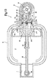
しかしながら、他の実施形態も可能である。図13は、本発明に係る装置の更なる例示的な実施形態の図2に似た断面図である。同じ参照符号は、同一又は同様の構成要素、要素、又は部品を指し、これらについて再度説明しない。図13の実施形態では、回転する切替部材の代わりに、並進する切替部材39が設けられる。切替部材39は、二重矢印f39に従って移動することができる。いくつかの実施形態では、切替部材39は、第1の蒸気供給ノズル37X、第2の蒸気供給ノズル37Y、及び第3の蒸気供給ノズル37Zから構成される蒸気供給装置を含む。蒸気供給ノズル37X、37Y、及び37Zは、切替部材39の位置に応じて、流体接続を、蒸気入口開孔部51と(第2の蒸気入口ダクト23ではなく)第1の蒸気導入ダクト21との間に、又は蒸気入口開孔部51と(第1の蒸気入口ダクト21ではなく)第2の蒸気入口ダクト23との間に、又は蒸気入口開孔部51と第1及び第2の蒸気入口ダクト21、23の両方との間に確立できるように構成及び配置される。
However, other embodiments are possible. FIG. 13 is a sectional view similar to FIG. 2 of a further exemplary embodiment of the device according to the invention. The same reference numbers refer to the same or similar components, elements or parts and will not be described again. In the embodiment of FIG. 13, a
具体的には、図13に示される中間位置では、切替部材39は、第3の中間蒸気供給ノズル37Zが、第1及び第2の蒸気入口ダクト21、23の両方を蒸気入口開孔部51と流体接続するような位置にある。
切替部材39を(図12で見て)上方に移動させることにより、流体接続が、第2の蒸気供給ノズル37Yを介して蒸気入口開孔部51と第2の蒸気入口ダクト23との間で確立される一方、第1の蒸気入口ダクト21は、蒸気入口開孔部51から分離される。
切替部材39を(再び図12で見て)下方に移動させることにより、流体接続が、第1の蒸気供給ノズル37Xを介して蒸気入口開孔部51と第1の蒸気入口ダクト21との間で確立される一方、第2の蒸気入口ダクト21は、蒸気入口開孔部51から分離される。
Specifically, at the intermediate position shown in FIG. 13, the switching
By moving the switching
By moving the switching
本明細書に記載された主題についての開示された実施形態は、図面に示されており、いくつかの例示的実施形態に関連して詳細且つ入念に完全に説明してきたが、当業者には、多くの修正、変更、及び省略が、本明細書に記載された新規な教示、原理、及び概念、並びに添付の特許請求の範囲に記載された主題の利点から実質的に逸脱することなく、可能であることが明らかであろう。従って、開示されたイノベーションの適切な範囲は、そのような修正、変更、及び省略の全てを包含するように、添付の特許請求の範囲の最も広範な解釈によってのみ決定すべきである。単語「備える、有する、含む(comprising)」は、請求項に記載されたもの以外の要素又はステップの存在を排除するものではない。ある要素に先行する単語「1つの(a,an)」は、複数のそのような要素の存在を排除するものではない。いくつかの手段を列挙する装置クレームにおいて、これらの手段のいくつかは、ハードウェアの同一のアイテムによって具現化し得る。特定の手段が互いに異なる従属請求項に記載されているという単なる事実は、これらの手段の組合せを有利に使用できないことを示すものではない。 The disclosed embodiments of the subject matter described in this specification are shown in the drawings and have been described in detail and in full detail in connection with some exemplary embodiments, but those skilled in the art will understand. Many modifications, changes and omissions may be made without substantial departure from the novel teachings, principles and concepts described herein, and the advantages of the claimed subject matter. It will be clear that this is possible. Accordingly, the proper scope of the disclosed innovation should be determined only by the broadest interpretation of the appended claims so as to encompass all such modifications, changes and omissions. The word “comprising” does not exclude the presence of elements or steps other than those listed in a claim. The word “a (an)” preceding an element does not exclude the presence of a plurality of such elements. In the device claim enumerating several means, several of these means can be embodied by one and the same item of hardware. The mere fact that certain measures are recited in mutually different dependent claims does not indicate that a combination of these measured cannot be used to advantage.
Claims (10)
第1の飲料通路と、第2の飲料通路と、蒸気供給装置とを含み、
第1の飲料通路は、
第1の飲料吸引ダクト及び第1の蒸気入口ダクトと連通する第1の飲料吸引チャンバであって、第1の飲料吸引ダクトは、飲料容器と連通するように構成される、第1の飲料吸引チャンバと、
吸気ポートと、
第1の飲料吸引ダクトを通して供給される飲料を前記吸気ポートからの空気と混合して、泡立てた飲料を製造するための泡立て装置と、
泡立てた飲料が分配される第1の飲料分配注ぎ口と、から構成され、
第2の飲料通路は、
第2の飲料吸引ダクト及び第2の蒸気入口ダクトと連通する第2の飲料吸引チャンバであって、第2の飲料吸引ダクトは、前記飲料容器と連通するように構成される、第2の飲料吸引チャンバから構成され、
前記蒸気供給装置は、蒸気供給源からの蒸気を受け取り、且つ泡立てたホット飲料を製造するために第1の蒸気入口ダクトに、泡立てないホット飲料を製造するために第2の蒸気入口ダクトに、又は洗浄目的のために第1の蒸気入口ダクト及び第2の蒸気入口ダクトの両方に蒸気を選択的に供給するように構成され、
前記蒸気供給装置は、単一の蒸気供給ノズル又は3つの蒸気供給ノズルを有する蒸気供給ノズル構成を含み、前記単一の蒸気供給ノズル及び3つの蒸気供給ノズルのうちの第3のノズルの一端の端部開口部が、第1の蒸気入口ダクトから第2の蒸気入口ダクトに及んでおり、
前記蒸気供給装置は、選択的に可動する移動可能な切替部材に配置され、
第1の切替位置では、前記単一の蒸気供給ノズル又は前記3つの蒸気供給ノズルのうちの第1のノズルは、蒸気を分配するために蒸気入口開孔部を前記第1の蒸気入口ダクトに流体的に接続して泡立てた飲料を製造し、
第2の切替位置では、前記単一の蒸気供給ノズル又は前記3つの蒸気供給ノズルのうちの第2のノズルは、蒸気を分配するために前記蒸気入口開孔部を前記第2の蒸気入口ダクトに流体的に接続して泡立てないホット飲料を製造し、
第3の切替位置では、前記単一の蒸気供給ノズル又は前記3つの蒸気供給ノズルのうちの第3のノズルは、前記端部開口部を第1の蒸気入口ダクト及び第2の蒸気入口ダクトの両方と流体的に接続し、それによって熱水及び/又は蒸気が洗浄目的のために第1の飲料通路及び第2の飲料通路の両方を通して供給され、且つ第1の飲料吸引ダクト及び第2の飲料吸引ダクトは、前記切替部材と一体的に移動可能なシャッターによって閉鎖される、
飲料泡立て装置。 A beverage whipping device, wherein the beverage whipping device is
Including a first beverage passage, a second beverage passage, and a steam supply device;
The first beverage passage is
A first beverage suction chamber in communication with a first beverage suction duct and a first steam inlet duct, wherein the first beverage suction duct is configured to communicate with a beverage container. A chamber;
An intake port;
A whipping device for producing a whipped beverage by mixing the beverage supplied through the first beverage suction duct with the air from the intake port;
A first beverage dispensing spout from which the whipped beverage is dispensed,
The second beverage passage is
A second beverage suction chamber in communication with a second beverage suction duct and a second steam inlet duct, wherein the second beverage suction duct is configured to communicate with the beverage container Consisting of a suction chamber,
The steam supply device receives steam from a steam source and in a first steam inlet duct to produce a whipped hot beverage, and in a second steam inlet duct to produce a whipped hot beverage, Or configured to selectively supply steam to both the first steam inlet duct and the second steam inlet duct for cleaning purposes;
The steam supply device includes a steam supply nozzle configuration having a single steam supply nozzle or three steam supply nozzles, at one end of a third nozzle of the single steam supply nozzle and the three steam supply nozzles. An end opening extends from the first steam inlet duct to the second steam inlet duct;
The steam supply device is disposed on a movable switching member that selectively moves,
In the first switching position, the first nozzle of the single steam supply nozzle or the three steam supply nozzles has a steam inlet opening in the first steam inlet duct for distributing steam. Producing fluidly connected and frothed beverages,
In the second switching position, the single steam supply nozzle or the second nozzle of the three steam supply nozzles connects the steam inlet opening to the second steam inlet duct for distributing steam. To produce a hot beverage that is fluidly connected to
In a third switching position, the single steam supply nozzle or a third nozzle of the three steam supply nozzles passes the end openings through the first steam inlet duct and the second steam inlet duct. Fluidly connected to both, whereby hot water and / or steam is supplied through both the first beverage passage and the second beverage passage for cleaning purposes , and the first beverage suction duct and the second The beverage suction duct is closed by a shutter that can move integrally with the switching member.
Beverage whipping device.
請求項1に記載の飲料泡立て装置。 The second beverage passage includes a second beverage dispensing spout from which non-foamed beverage is dispensed.
The beverage whipping device according to claim 1.
請求項1に記載の飲料泡立て装置。 The switching member is movable by rotation about a rotational axis to selectively move the steam supply nozzle to a first switching position, a second switching position, and a third switching position. is there,
The beverage whipping device according to claim 1.
請求項1に記載の飲料泡立て装置。 The switching member is in selective communication with the first beverage suction duct when the steam supply nozzle is in the first position and with the second beverage suction duct when the steam supply nozzle is in the second position. Further comprising a beverage supply duct that can provide
The beverage whipping device according to claim 1.
第1の端部開口部は、前記切替部材が移動する方向に寸法を有する蒸気分配チャンバと連通し、それによって第1の切替位置及び第2の切替位置の両方で、前記蒸気分配チャンバは、前記蒸気入口開孔部と連通して、前記蒸気入口開孔部と第1の蒸気入口ダクト又は第2の蒸気入口ダクトとの間の流れ接続を選択的に確立し、
前記蒸気供給ノズルの第2の端部開口部は、前記切替部材の位置に応じて、第1の蒸気入口ダクト及び第2の蒸気入口ダクトの一方のみと選択的に流体接続を確立するために十分に小さい断面を有する、
請求項1に記載の飲料泡立て装置。 The steam supply nozzle has a first end opening and a second end opening,
The first end opening communicates with a vapor distribution chamber having a dimension in the direction in which the switching member moves, whereby the vapor distribution chamber in both the first switching position and the second switching position is Selectively establishing a flow connection between the steam inlet aperture and the first steam inlet duct or the second steam inlet duct in communication with the steam inlet aperture;
The second end opening of the steam supply nozzle selectively establishes fluid connection with only one of the first steam inlet duct and the second steam inlet duct, depending on the position of the switching member. Having a sufficiently small cross-section,
The beverage whipping device according to claim 1.
請求項5に記載の飲料泡立て装置。 In the third switching position of the switching member, the second end opening of the steam supply nozzle faces the steam inlet opening, and the steam distribution chamber is connected to the steam supply nozzle and the first opening. Establishing communication between both the steam inlet duct and the second steam inlet duct;
The beverage whipping device according to claim 5.
請求項7に記載の飲料ジャグ。 A jug body and a jug cover, the jug cover supports the beverage frothing device,
The beverage jug according to claim 7 .
請求項9に記載の飲料製造マシン。 The beverage whipping device is supported by a beverage jug,
The beverage production machine according to claim 9 .
Applications Claiming Priority (3)
| Application Number | Priority Date | Filing Date | Title |
|---|---|---|---|
| EP13194776 | 2013-11-28 | ||
| EP13194776.4 | 2013-11-28 | ||
| PCT/EP2014/075529 WO2015078858A1 (en) | 2013-11-28 | 2014-11-25 | Beverage frothing device and jug comprising said device |
Publications (3)
| Publication Number | Publication Date |
|---|---|
| JP2017501769A JP2017501769A (en) | 2017-01-19 |
| JP2017501769A5 JP2017501769A5 (en) | 2017-09-21 |
| JP6336076B2 true JP6336076B2 (en) | 2018-06-06 |
Family
ID=49683549
Family Applications (1)
| Application Number | Title | Priority Date | Filing Date |
|---|---|---|---|
| JP2016534989A Expired - Fee Related JP6336076B2 (en) | 2013-11-28 | 2014-11-25 | Beverage whipping device and jug having this device |
Country Status (6)
| Country | Link |
|---|---|
| US (1) | US10092131B2 (en) |
| EP (1) | EP3073874B1 (en) |
| JP (1) | JP6336076B2 (en) |
| CN (1) | CN105992538B (en) |
| RU (1) | RU2667706C1 (en) |
| WO (1) | WO2015078858A1 (en) |
Families Citing this family (14)
| Publication number | Priority date | Publication date | Assignee | Title |
|---|---|---|---|---|
| GB2545512B (en) * | 2015-12-15 | 2020-04-15 | Douwe Egberts Bv | Selection valve and beverage system including same |
| ITUB20159657A1 (en) * | 2015-12-17 | 2017-06-17 | Caffitaly System Spa | EQUIPMENT FOR THE PREPARATION OF A BEVERAGE, IN PARTICULAR FOR A DRINK CONTAINING MILK |
| PT109611A (en) | 2016-09-13 | 2018-03-13 | Novadelta Comercio Ind Cafes Sa | DISPOSAL OF DISCHARGE OF COMPACT DRINKS AND PREPARATION MACHINE OF BEVERAGES WITH THE REFERENCE DISPOSAL OF DISCHARGE OF BEVERAGES |
| IT201600096851A1 (en) * | 2016-09-27 | 2018-03-27 | De Longhi Appliances Srl | DEVICE FOR EMULSION OF MILK WITH VENTURI EFFECT AND METHOD OF PRODUCTION OF HOT MILK WITH AND WITHOUT FOAM WITH SUCH A DEVICE |
| IT201600099780A1 (en) * | 2016-10-05 | 2018-04-05 | De Longhi Appliances Srl | VENTURI EFFECT MILK EMULSIFIER DEVICE |
| FR3086152B1 (en) * | 2018-09-24 | 2020-09-18 | Seb Sa | BEVERAGE PREPARATION MACHINE WITH ROTARY AGITATION DEVICE AND AIR VALVE FOR A HOT WATER AND / OR STEAM DELIVERY DUCT |
| TW202019330A (en) * | 2018-10-12 | 2020-06-01 | 義大利商辛巴利集團公司 | Steam dispensing apparatus for hot beverage preparation |
| CN109998367B (en) * | 2019-05-23 | 2021-01-05 | 南通天泉餐饮管理有限公司 | Electric rice cooker capable of preventing water dripping and defoaming |
| CN112806857B (en) * | 2019-09-12 | 2022-11-11 | 淮北智淮科技有限公司 | Anti-blocking cleaning device and cleaning method for steam nozzle of coffee machine |
| EP3838078A1 (en) * | 2019-12-19 | 2021-06-23 | Koninklijke Philips N.V. | A mixing apparatus |
| TWI715443B (en) * | 2020-02-19 | 2021-01-01 | 迅智自動化科技股份有限公司 | Beverage brewing apparatus |
| PL4014802T3 (en) * | 2020-12-21 | 2023-09-18 | Koninklijke Philips N.V. | A mixing apparatus for, for example, creating frothed milk |
| CN116998881B (en) * | 2023-08-30 | 2025-07-11 | 浙江比依电器股份有限公司 | Steam valve assembly and coffee machine with same |
| CN118576091A (en) * | 2023-12-29 | 2024-09-03 | 苏州咖乐美咖啡机科技有限公司 | Emulsification equipment and beverage machine |
Family Cites Families (17)
| Publication number | Priority date | Publication date | Assignee | Title |
|---|---|---|---|---|
| JPS5282234U (en) | 1975-12-18 | 1977-06-20 | ||
| IT206829Z2 (en) | 1986-04-18 | 1987-10-01 | Nuova Faema Spa | SIMILAR, ESPECIALLY FOR EMULSIFIER GROUP FOR ESPRESSO COFFEE MACHINES TO EMULSATE AIR, STEAM AND BAR MILK. FOR THE OBTAINING OF CAPPUCCINI AND |
| US5207148A (en) * | 1990-06-25 | 1993-05-04 | Caffe Acorto, Inc. | Automated milk inclusive coffee apparatus |
| NL1002936C2 (en) * | 1996-04-24 | 1997-10-28 | Sara Lee De Nv | Assembly for preparing hot and frothed milk. |
| US6289796B1 (en) * | 2001-02-23 | 2001-09-18 | Simatelex Manufactory Company Limited | Hot milk dispenser |
| FR2875106B1 (en) | 2004-09-10 | 2006-11-03 | Seb Sa | DEVICE FOR PRODUCING MILK EMULSION AND COFFEE MACHINE COMPRISING SUCH A DEVICE |
| JP2006284145A (en) | 2005-04-05 | 2006-10-19 | Corona Corp | Storage type hot water supply bath device |
| WO2008071024A1 (en) | 2006-12-12 | 2008-06-19 | Jura Elektroapparate Ag | Beverage preparation machine with a pinch valve |
| EP2050368B1 (en) | 2007-10-16 | 2010-04-14 | Gruppo Cimbali S.p.A. | Coffee machine with dispenser of a ready prepared chocolate-based beverage |
| BRPI0822818A2 (en) | 2008-06-25 | 2015-06-30 | Swiss Caffe Asia Ltd | Device for heating and / or frothing milk for hot beverage machines and hot beverage machine |
| ITFI20080198A1 (en) * | 2008-10-15 | 2010-04-16 | Saeco Ipr Ltd | "COFFEE MACHINE'" |
| DE202008016400U1 (en) | 2008-12-12 | 2009-03-05 | Eugster/Frismag Ag | Multiway valve arrangement in a beverage preparation unit |
| DE102009001752A1 (en) | 2009-03-23 | 2010-09-30 | BSH Bosch und Siemens Hausgeräte GmbH | Vending Machine |
| DE202009013064U1 (en) | 2009-09-29 | 2010-02-11 | Eugster/Frismag Ag | Coffee / espresso machine with a milk froth maker for cappuccino |
| DE102010007143B4 (en) * | 2010-02-05 | 2013-08-22 | Eugster/Frismag Ag | Coffee machine with a foaming device and means for cleaning the foaming device and a milk suction line and method for rinsing the milk suction line |
| RU2571198C2 (en) | 2010-06-18 | 2015-12-20 | Конинклейке Филипс Электроникс Н.В. | Fluid foamer |
| DE202012009074U1 (en) | 2012-09-21 | 2012-11-08 | Eugster/Frismag Ag | Device for the preparation of either cold or warm milk froth or delivery of either cold or warm milk |
-
2014
- 2014-11-25 WO PCT/EP2014/075529 patent/WO2015078858A1/en not_active Ceased
- 2014-11-25 US US15/037,369 patent/US10092131B2/en active Active
- 2014-11-25 RU RU2016125319A patent/RU2667706C1/en active
- 2014-11-25 EP EP14803100.8A patent/EP3073874B1/en active Active
- 2014-11-25 JP JP2016534989A patent/JP6336076B2/en not_active Expired - Fee Related
- 2014-11-25 CN CN201480065079.4A patent/CN105992538B/en active Active
Also Published As
| Publication number | Publication date |
|---|---|
| RU2667706C1 (en) | 2018-09-24 |
| CN105992538B (en) | 2019-02-22 |
| CN105992538A (en) | 2016-10-05 |
| EP3073874B1 (en) | 2017-11-08 |
| US10092131B2 (en) | 2018-10-09 |
| RU2016125319A (en) | 2018-01-10 |
| JP2017501769A (en) | 2017-01-19 |
| US20160296063A1 (en) | 2016-10-13 |
| EP3073874A1 (en) | 2016-10-05 |
| WO2015078858A1 (en) | 2015-06-04 |
Similar Documents
| Publication | Publication Date | Title |
|---|---|---|
| JP6336076B2 (en) | Beverage whipping device and jug having this device | |
| JP2011525393A (en) | A device that is used in hot beverage production machines such as cappuccino and that heats and / or froths milk | |
| US9049961B2 (en) | Liquid cartridge for use in a beverage system | |
| RU2691298C2 (en) | Milk frother, beverage preparation system and beverage preparation machine | |
| CA2708473C (en) | Beverage preparation machine and method for cleaning a beverage preparation machine | |
| RU2691299C2 (en) | Device for foaming milk | |
| RU2526011C2 (en) | Milk foam production device | |
| RU2691449C2 (en) | Device for foaming milk | |
| ITFI20080198A1 (en) | "COFFEE MACHINE'" | |
| RU2649263C2 (en) | Jug for beverages and beverage producing machine comprising said jug | |
| JP5086263B2 (en) | Beverage preparation system comprising a beverage maker and a cartridge removably disposed in the beverage maker | |
| CN103169373A (en) | Coffee/espresso machine with a milk froth generating device for the preparation of cappuccino | |
| JP2017501769A5 (en) | ||
| CN100551313C (en) | Pump units and disposable sets for use in beverage machines | |
| ITUA20163857A1 (en) | AUTOMATIC EQUIPMENT FOR HEATING AND MOUNTING THE MILK AND ITS METHOD. | |
| CN102379632A (en) | Device for foaming milk in hot beverage machine | |
| US20160113436A1 (en) | Device for frothing a liquid | |
| CN111356388B (en) | Beverage vending machine | |
| JP5144521B2 (en) | Beverage making unit for use in a process for preparing a beverage based on at least two fluids | |
| WO2009071247A1 (en) | Device for the production of milk foam or the like | |
| RU2805221C1 (en) | Mixing device, for example, for preparing foamed milk | |
| HK1225244A1 (en) | Milk frothing device | |
| HK1225243A1 (en) | Milk frothing device, beverage preparation system and machine for preparing beverages |
Legal Events
| Date | Code | Title | Description |
|---|---|---|---|
| A521 | Request for written amendment filed |
Free format text: JAPANESE INTERMEDIATE CODE: A523 Effective date: 20160728 |
|
| A521 | Request for written amendment filed |
Free format text: JAPANESE INTERMEDIATE CODE: A523 Effective date: 20170809 |
|
| A621 | Written request for application examination |
Free format text: JAPANESE INTERMEDIATE CODE: A621 Effective date: 20170809 |
|
| A871 | Explanation of circumstances concerning accelerated examination |
Free format text: JAPANESE INTERMEDIATE CODE: A871 Effective date: 20170809 |
|
| A975 | Report on accelerated examination |
Free format text: JAPANESE INTERMEDIATE CODE: A971005 Effective date: 20170823 |
|
| A131 | Notification of reasons for refusal |
Free format text: JAPANESE INTERMEDIATE CODE: A131 Effective date: 20170912 |
|
| A521 | Request for written amendment filed |
Free format text: JAPANESE INTERMEDIATE CODE: A523 Effective date: 20171026 |
|
| A131 | Notification of reasons for refusal |
Free format text: JAPANESE INTERMEDIATE CODE: A131 Effective date: 20171205 |
|
| A521 | Request for written amendment filed |
Free format text: JAPANESE INTERMEDIATE CODE: A523 Effective date: 20180116 |
|
| TRDD | Decision of grant or rejection written | ||
| A01 | Written decision to grant a patent or to grant a registration (utility model) |
Free format text: JAPANESE INTERMEDIATE CODE: A01 Effective date: 20180403 |
|
| A61 | First payment of annual fees (during grant procedure) |
Free format text: JAPANESE INTERMEDIATE CODE: A61 Effective date: 20180501 |
|
| R150 | Certificate of patent or registration of utility model |
Ref document number: 6336076 Country of ref document: JP Free format text: JAPANESE INTERMEDIATE CODE: R150 |
|
| LAPS | Cancellation because of no payment of annual fees |