JP6303974B2 - In-vehicle camera device and in-vehicle system - Google Patents
In-vehicle camera device and in-vehicle system Download PDFInfo
- Publication number
- JP6303974B2 JP6303974B2 JP2014215644A JP2014215644A JP6303974B2 JP 6303974 B2 JP6303974 B2 JP 6303974B2 JP 2014215644 A JP2014215644 A JP 2014215644A JP 2014215644 A JP2014215644 A JP 2014215644A JP 6303974 B2 JP6303974 B2 JP 6303974B2
- Authority
- JP
- Japan
- Prior art keywords
- vehicle
- camera module
- windshield
- processing
- camera
- Prior art date
- Legal status (The legal status is an assumption and is not a legal conclusion. Google has not performed a legal analysis and makes no representation as to the accuracy of the status listed.)
- Active
Links
Images





Classifications
-
- B—PERFORMING OPERATIONS; TRANSPORTING
- B60—VEHICLES IN GENERAL
- B60R—VEHICLES, VEHICLE FITTINGS, OR VEHICLE PARTS, NOT OTHERWISE PROVIDED FOR
- B60R11/00—Arrangements for holding or mounting articles, not otherwise provided for
- B60R11/04—Mounting of cameras operative during drive; Arrangement of controls thereof relative to the vehicle
-
- G—PHYSICS
- G03—PHOTOGRAPHY; CINEMATOGRAPHY; ANALOGOUS TECHNIQUES USING WAVES OTHER THAN OPTICAL WAVES; ELECTROGRAPHY; HOLOGRAPHY
- G03B—APPARATUS OR ARRANGEMENTS FOR TAKING PHOTOGRAPHS OR FOR PROJECTING OR VIEWING THEM; APPARATUS OR ARRANGEMENTS EMPLOYING ANALOGOUS TECHNIQUES USING WAVES OTHER THAN OPTICAL WAVES; ACCESSORIES THEREFOR
- G03B17/00—Details of cameras or camera bodies; Accessories therefor
- G03B17/55—Details of cameras or camera bodies; Accessories therefor with provision for heating or cooling, e.g. in aircraft
-
- G—PHYSICS
- G06—COMPUTING OR CALCULATING; COUNTING
- G06V—IMAGE OR VIDEO RECOGNITION OR UNDERSTANDING
- G06V20/00—Scenes; Scene-specific elements
- G06V20/50—Context or environment of the image
- G06V20/56—Context or environment of the image exterior to a vehicle by using sensors mounted on the vehicle
-
- H—ELECTRICITY
- H04—ELECTRIC COMMUNICATION TECHNIQUE
- H04N—PICTORIAL COMMUNICATION, e.g. TELEVISION
- H04N23/00—Cameras or camera modules comprising electronic image sensors; Control thereof
- H04N23/50—Constructional details
- H04N23/51—Housings
-
- H—ELECTRICITY
- H04—ELECTRIC COMMUNICATION TECHNIQUE
- H04N—PICTORIAL COMMUNICATION, e.g. TELEVISION
- H04N23/00—Cameras or camera modules comprising electronic image sensors; Control thereof
- H04N23/57—Mechanical or electrical details of cameras or camera modules specially adapted for being embedded in other devices
-
- H—ELECTRICITY
- H04—ELECTRIC COMMUNICATION TECHNIQUE
- H04N—PICTORIAL COMMUNICATION, e.g. TELEVISION
- H04N7/00—Television systems
- H04N7/18—Closed-circuit television [CCTV] systems, i.e. systems in which the video signal is not broadcast
- H04N7/181—Closed-circuit television [CCTV] systems, i.e. systems in which the video signal is not broadcast for receiving images from a plurality of remote sources
-
- B—PERFORMING OPERATIONS; TRANSPORTING
- B60—VEHICLES IN GENERAL
- B60R—VEHICLES, VEHICLE FITTINGS, OR VEHICLE PARTS, NOT OTHERWISE PROVIDED FOR
- B60R11/00—Arrangements for holding or mounting articles, not otherwise provided for
- B60R2011/0001—Arrangements for holding or mounting articles, not otherwise provided for characterised by position
- B60R2011/0003—Arrangements for holding or mounting articles, not otherwise provided for characterised by position inside the vehicle
- B60R2011/0026—Windows, e.g. windscreen
Landscapes
- Engineering & Computer Science (AREA)
- Multimedia (AREA)
- Signal Processing (AREA)
- Physics & Mathematics (AREA)
- General Physics & Mathematics (AREA)
- Mechanical Engineering (AREA)
- Aviation & Aerospace Engineering (AREA)
- Theoretical Computer Science (AREA)
- Traffic Control Systems (AREA)
- Fittings On The Vehicle Exterior For Carrying Loads, And Devices For Holding Or Mounting Articles (AREA)
- Studio Devices (AREA)
Description
本発明は、車載カメラ装置に関する。 The present invention relates to an in-vehicle camera device.
車両のフロントガラスの内側にカメラ装置を設置し、当該カメラ装置による撮像画像に基づき車両の前方に存在する人や車両等を認識する技術が知られている。この種のカメラ装置は、例えば、炎天下において太陽光が照りつけることなどにより高温になりやすく、耐熱温度を超過してしまうことが生じ得る。そこで、特許文献1に記載のカメラ装置では、筐体表面部に赤外線反射材が設けられている。このような構成によれば、太陽光に含まれる赤外線が赤外線反射材により反射され、カメラ装置の温度上昇が抑制される。
A technique is known in which a camera device is installed inside a windshield of a vehicle, and a person or vehicle existing in front of the vehicle is recognized based on an image captured by the camera device. This type of camera device is likely to become hot due to, for example, sunlight shining in the sun, and may exceed the heat-resistant temperature. Therefore, in the camera device described in
特許文献1に記載のカメラ装置では、赤外線が反射されることでカメラ装置の温度上昇が抑制されるが、カメラ装置自体が冷却されるわけではないため、何らかの理由でカメラ装置が高温になってしまった場合には速やかに温度を低下させることができない。一方、この種のカメラ装置では、車両外の環境が低温のとき(例えば冬等)に、フロントガラスにおけるカメラ装置の前方に位置する部分が曇ることで撮像に支障を来すという別の問題もある。
In the camera device described in
本発明は、フロントガラスの内側に設置されたカメラ装置の冷却を促進し、かつ、フロントガラスにおけるカメラ装置の前方に位置する部分の曇りを抑制することのできるカメラ装置を提供することを目的とする。 It is an object of the present invention to provide a camera device that can promote cooling of a camera device installed inside a windshield and suppress fogging of a portion of the windshield located in front of the camera device. To do.
本発明の一側面は、車載カメラ装置であって、カメラモジュールと、制御回路基板と、筐体と、ブラケットと、フードと、第1の熱伝導部材と、を備える。カメラモジュールは、車両の前方を撮像する。制御回路基板は、車両の前方の状況を認識する認識処理をカメラモジュールによる撮像画像に基づき実行し、車線逸脱警報処理、ヘッドライト制御処理及び前方衝突回避処理のうち少なくとも2つの車両制御処理を認識処理の認識結果に基づき実行する。筐体は、カメラモジュール及び制御回路基板を収容する。ブラケットは、筐体を車両のフロントガラスに固定するための部材であって、筐体が当該部材を介してフロントガラスに固定された状態において筐体とフロントガラスとを対向させる開口部が形成されている。フードは、カメラモジュールを覆うように配置される。第1の熱伝導部材は、ブラケットに形成された開口部において筐体とフロントガラスとに接するように設けられる。 One aspect of the present invention is an in-vehicle camera device including a camera module, a control circuit board, a housing, a bracket, a hood, and a first heat conducting member. The camera module images the front of the vehicle. The control circuit board executes a recognition process for recognizing a situation in front of the vehicle based on an image captured by the camera module, and recognizes at least two vehicle control processes among a lane departure warning process, a headlight control process, and a front collision avoidance process. Execute based on the recognition result of the process. The housing accommodates the camera module and the control circuit board. The bracket is a member for fixing the casing to the windshield of the vehicle, and an opening is formed to face the casing and the windshield in a state where the casing is fixed to the windshield via the member. ing. The hood is disposed so as to cover the camera module. The first heat conducting member is provided in contact with the housing and the windshield at the opening formed in the bracket.
このような構成によれば、カメラ装置の冷却を促進しつつ、フロントガラスにおけるカメラ装置の前方に位置する部分の曇りを抑制することができる。 According to such a configuration, it is possible to suppress fogging of a portion of the windshield positioned in front of the camera device while promoting cooling of the camera device.
以下、本発明の例示的な実施形態について図面を参照しながら説明する。また、下記の実施形態の説明で用いる符号を特許請求の範囲にも適宜使用しているが、これは本発明の理解を容易にする目的で使用しており、本発明の技術的範囲を限定する意図ではない。 Hereinafter, exemplary embodiments of the present invention will be described with reference to the drawings. Further, the reference numerals used in the description of the following embodiments are also used in the claims as appropriate, but this is used for the purpose of facilitating the understanding of the present invention, and limits the technical scope of the present invention. Not intended.
[1.構成]
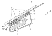
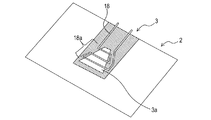
図1及び図2に示すカメラ装置1は、車両のフロントガラス2に内側(車室側)から取り付けられ、フロントガラス2の上部における中央(ルームミラーの近く)に設置される。カメラ装置1は、画像センサ11、ブラケット12、フード13、第1の熱伝導部材14、第2の熱伝導部材15、カバー16、換気ファン17及び熱線18を備える。図1及び図2においては、フロントガラス2の一部が図示されており、図2では、説明の便宜上、換気ファン17及び熱線18が省略されている。なお、以下では、カメラ装置1が搭載された車両を「自車両」という。
[1. Constitution]
The
図3に示すように、画像センサ11は、カメラモジュール111、電気接続配線112、制御回路基板113、筐体114及び下部カバー115を備える。
カメラモジュール111は、レンズ111a及びレンズ鏡筒部111bを備える、自車両の前方を撮像するための装置である。レンズ鏡筒部111bは、円筒状の部位であり、その内部にてレンズ111aを保持する。
As shown in FIG. 3, the
The
電気接続配線112は、カメラモジュール111と制御回路基板113とを電気的に接続するための部品である。
制御回路基板113は、CPU、ROM及びRAMを中心とする周知のマイクロコンピュータを備える板状の部品であり、自車両の前方の状況を認識する認識処理を、カメラモジュール111による撮像画像に基づき実行する。また、制御回路基板113は、認識処理の認識結果に基づき、自車両に搭載された機器を制御するための車両制御処理を実行する。なお、認識処理によって認識される認識対象、及び、車両制御処理の処理内容については後述する。
The
The
筐体114は、下方が開放された、側壁及び上壁を有する容器状の部材であり、カメラモジュール111、電気接続配線112及び制御回路基板113を上方から覆うようにして収容する。また、筐体114におけるガラス側壁部1141には、カメラモジュール111のレンズ鏡筒部111bをフロントガラス2側に露出させるための切欠部1142が形成されている。ここで、ガラス側壁部1141とは、後述する方法でブラケット12を介して筐体114がフロントガラス2に固定された状態において、筐体114内部のカメラモジュール111よりもフロントガラス2側に位置する筐体114の上壁の一部である。
The
下部カバー115は、筐体114の下方を閉じるための部材である。
一方、図1及び図2に示すブラケット12は樹脂からできた概略板状の部材であり、その中央部には開口部12aが形成され、開口部12aを囲む領域には当該ブラケット12
がU字形状となるように欠損した欠損部12bが形成されている。ブラケット12は、画像センサ11の筐体114をフロントガラス2に固定するための部材である。すなわち、ブラケット12の表面であって厚み方向に垂直な面の一方がフロントガラス2に固定(この例では接着)され、固定されたブラケット12に筐体114が組み付けられることで筐体114がフロントガラス2に固定される。このようにブラケット12を介して筐体114がフロントガラス2に固定された状態において、ブラケット12には開口部12aが形成されているため、筐体114とフロントガラス2とは対向する。ここでいう「対向」とは、筐体114とフロントガラス2との間に何ら部材がない状態において筐体114とフロントガラス2とが互いに向き合うことを意味する。また、ブラケット12の欠損部12bは、筐体114から露出したカメラモジュール111の前方に位置する。この欠損部12bは、カメラモジュール111の画角範囲に対応するように、カメラモジュール111の撮像方向の前方に向かって幅が広くなる台形状に形成されており、カメラモジュール111の視界が確保されるようになっている。
The
On the other hand, the
A
フード13は、台形状の底面と、台形状の底面の底辺以外の2辺に立設された2つの側面と、を有する樹脂製の部材である。フード13は、ブラケット12の欠損部12bにはめ込まれて使用され、本実施形態では、フード13がはめ込まれたブラケット12に筐体114が組み付けられることにより、フード13がカメラモジュール111のレンズ鏡筒部111bを覆う構成となる。ここで、フード13の底面がカメラモジュール111のレンズ鏡筒部111bより下方に位置するように、フード13は配置される。このようにフード13が配置されることにより、カメラモジュール111の画角範囲外の景色のレンズ111aへの映り込みが抑制される。
The
第1の熱伝導部材14は、その熱伝導率が1[W/m・K]以上50[W/m・K]以下であるようなシリコン系のシート部材であり、粘着性を有し、接触した物に貼り付く性質を備える。第1の熱伝導部材14は、ブラケット12に形成された開口部12aにおいて筐体114とフロントガラス2とに接するように設けられる。本実施形態では、まず、第1の熱伝導部材14が筐体114のガラス側壁部1141に貼り付けられて接着され、その後、筐体114がブラケット12を介してフロントガラス2に固定されることで、第1の熱伝導部材14がフロントガラス2に密着し、接着される。ここで、第1の熱伝導部材14は、筐体114のガラス側壁部1141の上面と同様な大きさ及び形状を有している。そのため、第1の熱伝導部材14は、ガラス側壁部1141における切欠部1142よりもカメラモジュール111の撮像方向の後方に位置する領域1141aに接している。また、第1の熱伝導部材14は、ガラス側壁部1141における切欠部1142を挟む両側の領域1141bにも接している。
The first thermal
第2の熱伝導部材15は、第1の熱伝導部材14の素材と同一素材からできたシート部材であり、ブラケット12とフロントガラス2との間に位置し、ブラケット12とフロントガラス2とに接するように設けられる。本実施形態では、第2の熱伝導部材15は、ブラケット12の上面と同様な大きさ及び形状を有し、ブラケット12の上面全体に貼り付けられる。第2の熱伝導部材15は、接着剤を用いることでブラケット12及びフロントガラス2に固定される。本実施形態では、第2の熱伝導部材15をフロントガラス2に固定するための接着剤等が自車両の外から視認されることを抑制するために、黒セラミック3を介して第2の熱伝導部材15がフロントガラス2に取り付けられる。ここで、黒セラミック3には、カメラモジュール111の視界を遮らないようにするため、カメラモジュール111の画角範囲に相当する台形状の欠損部3aが形成されている。
The second
カバー16は、上方が開放された、側面及び下面を有する容器状の部材であり、画像センサ11、ブラケット12及びフード13を下方から覆い、これらの構成が自車両の車室内から視認されにくくする。本実施形態では、カバー16の下面には、貫通孔16aが形
成されている。
The
換気ファン17は、カバー16の内部に存在する空気を入れ換えるための装置であり、カバー16に形成された貫通孔16aにはめ込まれた状態でカバー16に固定される。
熱線18は、フロントガラス2におけるカメラモジュール111のレンズ111aの前方に位置する部分を加熱する。本実施形態では、熱線18は銅線であり、熱線18の両端は自車両に配置された図示しない電源に接続され、通電されることにより、熱線18が発熱する。熱線18は、図4に示すように、フロントガラス2及び黒セラミック3の車室側の表面に沿うように配置される。すなわち、熱線18は、S字状に折り曲げられたS字状部位18aを備え、S字状部位18aが黒セラミック3の欠損部3aに重ねられることで、台形状である欠損部3aの高さ方向と垂直に欠損部3aを複数回横切るように配置される。
The
The
次に、カメラ装置1の電気的な機能について図5を用いて説明する。図5においては、カメラ装置1の構成のうち電気的な機能を有さないブラケット12やフード13等は省略されている。自車両は、共通のバス4に接続された検出部5、センサ部6、運動部7、ヒューマンマシンインタフェース部(以下「HMI部」という。)8、認識部9及び制御部10を備える。
Next, the electrical functions of the
検出部5は、自車両の周辺の状況を検出するための装置として、車載カメラ51及びレーダ装置52を備える。車載カメラ51は、右側方カメラ511、左側方カメラ512、後方カメラ513及び先述したカメラモジュール111を備える。右側方カメラ511は、自車両右側のサイドミラーに設置され、自車両右側方を撮像する。左側方カメラ512は、自車両左側のサイドミラーに設置され、自車両左側方を撮像する。後方カメラ513は、自車両後方のリアバンパーに設置され、自車両の後方を撮像する。
The
レーダ装置52は、ミリ波帯又はレーザ光によるレーダ波を送受信することによって所定の探査範囲内に存在するレーダ波を反射した物体を検出する周知のものであり、車両からの距離、車両との相対速度、及び車両に対する横位置を少なくとも含んだ対象物情報を生成して後述する認識部9に出力する。また、レーダ装置として、超音波を発信し、所定の方向にある物体からの反射波により物体を検出するソナー(図示せず)を備えてもよい。
The
センサ部6は、自車両に搭載された機器の状態を検出するための装置として、温度センサ61を備える。温度センサ61は、カメラモジュール111の近傍に設置され、カメラモジュール111の温度を検出する。
The
運動部7は、自車両におけるボディ系、パワートレイン系及びシャーシ系の制御の制御対象となる装置として、車両の進行方向を変更する操舵装置71、減速やエネルギー回生を行うブレーキ72、エンジンやモーター等の発動機からなり車両を推進する動力発生装置73、回転速度とトルクの変換を行い動力を伝達する変速機74、ヘッドライト75、進路変更や右左折時の合図を行う方向指示器76及びガラスに付着した雨滴、雪、汚れ等により視界が不良となる場合に付着物を除去するワイパ77を備える。
The
HMI部8は、人間と装置とのコミュニケーションのためのインタフェースを提供するための装置として、ブザー81、スピーカ82、インジケータ83及びセンタコンソール内に設けられたナビゲーションディスプレイやセンタコンソール上に設けられたヘッドアップディスプレイなどのディスプレイ84を備える。また、電動モータなどからなりステアリングやシートを振動させる加振器(図示なし)やステアリングやブレーキペダルに反力を発生させる反力生成器(図示なし)を備え、これらの機器を作動させることにより装
置から人間に対して情報伝達を行ってもよい。また、後述する認識部や制御部における認識処理の感度(認識のし易さの段階)や判断処理の処理タイミングを調整するための感度調整器を備え、人間から装置へ情報伝達を行ってもよい。
The
認識部9は、制御回路基板113に実装された回路の一部位であり、自車両の周辺の状況を認識する認識処理を、車載カメラ51による撮像画像及びレーダ装置52の検出結果に基づき実行する。なお、以下では、車載カメラ51のカメラモジュール111による撮像画像に基づく認識処理を「第1の認識処理」、レーダ装置52による検出結果に基づく認識処理を「第2の認識処理」という。本実施形態では、認識部9は、認識処理により、車線、道路形状、路面状態、光源、先行車両、対向車両、静止車両、先行歩行者、対向歩行者、静止者、自動二輪車、自転車、障害物、路側物、標識、交通信号、道路標示、看板、トンネル、退避領域、カメラモジュール111の視界を遮るもの、気象環境及び建造物を認識する。
The
ここで、道路形状とは、道路の曲率や勾配等を意味し、路面状態とは、例えば、雨や雪等により光が反射しやすくなった路面の状態等を意味する。また、光源としては、例えば、先行車両のテールライトや対向車両のヘッドライト等が挙げられる。また、先行歩行者とは、自車両の前方を自車両の進行方向と同方向に歩いている歩行者であり、対向歩行者とは、自車両の前方を自車両の進行方向と逆方向に歩いている歩行者であり、静止者とは、静止している者である。障害物としては、例えば、岩等が挙げられ、路側物としては、例えば、縁石、ガードレール、ポール、樹木、塀、建物、駐車車両、駐輪車両等の路側障害物や電柱等が挙げられる。また、退避領域とは、後方から接近して来る車両等を回避するための道路の脇に設けられた領域である。カメラモジュール111の視界を遮るものとしては、例えば、フロントガラス2におけるカメラモジュール111のレンズ111aの前方に位置する部分又はレンズ111aに付着した汚れや、フロントガラス2の上記部分に貼り付いた紙等の貼付物等が挙げられる。また、気象環境としては、例えば、雨、雪、霧や逆光等が挙げられる。
Here, the road shape means a curvature or gradient of the road, and the road surface state means a road surface state where light is easily reflected by rain or snow, for example. Moreover, as a light source, the taillight of a preceding vehicle, the headlight of an oncoming vehicle, etc. are mentioned, for example. A preceding pedestrian is a pedestrian walking in front of the host vehicle in the same direction as the traveling direction of the host vehicle, and an oncoming pedestrian is traveling in the direction opposite to the traveling direction of the host vehicle. A pedestrian who is walking and a stationary person is a stationary person. Examples of the obstacle include rocks, and examples of the roadside object include roadside obstacles such as curbs, guardrails, poles, trees, fences, buildings, parking vehicles, bicycle parking vehicles, and utility poles. The retreat area is an area provided on the side of the road for avoiding vehicles approaching from the rear. Examples of the
また、車線は、道路の白線の位置を認識することにより認識される。白線の位置は、カメラモジュール111による撮像画像に対して、周知の白線認識処理(例えば、画像二値化及びハフ変換を用いた白線認識処理)を行うことで、認識される。また、光源は、カメラモジュール111による撮像画像に対して、周知の認識処理を逐次行うことで認識される。すなわち、認識部9は、撮像画像に写された物体のうち所定値以上の輝度、所定の形状に近い形状及び所定の色に近い色等を有する物体を光源として認識し、撮像画像におけるその位置座標を特定する。また、認識部9は、例えば、その光源が先行車両のテールライトであること、又は、その光源が対向車両のヘッドライトであること、を認識する。ここで、認識部9は、例えば、光源の色が赤色に近い所定の範囲内の色であればその光源を先行車両のテールライトであると認識し、光源の色が白色に近い所定の範囲内の色であればその光源が対向車両のヘッドライトであると認識する。
The lane is recognized by recognizing the position of the white line on the road. The position of the white line is recognized by performing a known white line recognition process (for example, a white line recognition process using image binarization and Hough transform) on the image captured by the
制御部10は、制御回路基板113に実装された回路の一部位であり、認識部9の認識結果に基づき車両制御処理を実行する。本実施形態では、制御部10は、車両制御処理として、車線逸脱警報処理、車線維持処理、ヘッドライト制御処理、出会頭衝突回避処理、交差点衝突回避処理、前方衝突回避処理、標識表示処理、制限速度表示処理、制限速度超過警報処理、オートワイパ処理、車線変更支援処理、アラウンドビュー表示処理、自動駐車処理、全車速アダプティブクルーズコントロール処理、ブラインドスポット警報処理、後方クロストラフィック警報処理、前方クロストラフィック警報処理、車間警報処理、追突警報処理及び誤発進防止処理を実行する。
The
ここでいう車線逸脱警報処理とは、制御部10が、車線逸脱判定を行い、車線逸脱判定
の判定結果に応じて、ブザー81及びスピーカ82に自車両の乗員に対する警告を音声出力させる処理である。ここで、車線逸脱判定とは、自車両が車線を逸脱するおそれがあるか否かの判定及び自車両が車線を逸脱しているか否かの判定である。車線逸脱警報処理は、車線及び道路形状等に関する認識結果に基づき実行される。
Here, the lane departure warning process is a process in which the
車線維持処理とは、自車両が車線から逸脱しないように操舵装置71を制御する処理であり、車線及び道路形状等に関する認識結果に基づき実行される。
ヘッドライト制御処理とは、自車両のヘッドライト75のハイビームとロービームとを切り替える制御、又は、ヘッドライト75の光軸方向をスイブル(Swivel:旋回)させる制御、を実行する処理である。ヘッドライト制御処理は、車線、道路形状、路面状態及び光源等に関する認識結果に基づき実行される。
The lane keeping process is a process for controlling the
The headlight control process is a process of executing control for switching between the high beam and the low beam of the
出会頭衝突回避処理とは、交差点の手前で自車両の前方を横断している車両等と自車両とが衝突する可能性がある場合に、衝突を回避するように操舵装置71やブレーキ72等の自車両の運動にかかわる制御対象を制御する処理である。交差点衝突回避処理とは、自車両が交差点を曲がっているときに歩行者や車両等と自車両とが衝突する可能性がある場合に、衝突を回避するように操舵装置71やブレーキ72等の自車両の運動にかかわる制御対象を制御する処理である。前方衝突回避処理とは、先行車両等と自車両とが衝突する可能性がある場合に、衝突を回避するように操舵装置71やブレーキ72等の自車両の運動にかかわる制御対象を制御する処理である。また、出会頭衝突回避処理、交差点衝突回避処理及び前方衝突回避処理には、看板又はトンネルが認識された場合であって自車両が当該看板の下又は当該トンネルを通過できない場合にブザー81及びスピーカ82に警告を音声出力させる処理も含まれる。なお、出会頭衝突回避処理及び交差点衝突回避処理は、路面状態、先行車両、対向車両、静止車両、先行歩行者、対向歩行者、静止者、自動二輪車、自転車、障害物、路側物、看板及びトンネル等に関する認識結果に基づき実行される。また、前方衝突回避処理は、出会頭衝突回避処理及び交差点衝突回避処理を実行する際に使用される認識結果に加えて退避領域に関する認識結果に基づき実行される。
The head-on collision avoidance process is a
標識表示処理とは、標識、交通信号、道路標示及び看板の指示内容等をディスプレイ84に表示させる処理であり、標識、交通信号、道路標示及び看板等に関する認識結果に基づき実行される。また、制限速度表示処理とは、標識に示された制限速度をディスプレイ84に表示させる処理であり、標識等の認識結果に基づき実行される。
The sign display process is a process of displaying signs, traffic signals, road markings, instruction contents of signboards, and the like on the
制限速度超過警報処理とは、自車両の速度が制限速度を超過している場合に、ブザー81及びスピーカ82に自車両の乗員に対する警告を音声出力させる処理であり、標識等に関する認識結果に基づき実行される。
The speed limit excess warning process is a process in which the
オートワイパ処理とは、降雨等に応じてワイパ77の動作を制御する処理であり、路面状態及び気象環境等に関する認識結果に基づき視認性低下の状況を判断して実行される。
車線変更支援処理とは、ドライバの車線変更を支援するように操舵装置71、ブレーキ72、変速機74及び方向指示器76を制御する処理であり、例えば、隣接車線を走行する車両を検出し、車線変更時ドライバに報知する。また、アラウンドビュー表示処理とは、自車両の全周囲の撮像画像をディスプレイ84に表示させる処理である。また、自動駐車処理とは、自動で駐車を行うように操舵装置71及びブレーキ72を制御する処理であり、全車速アダプティブクルーズコントロール処理とは、先行車両に追従して走行するようにブレーキ72、動力発生装置73及び変速機74を制御する処理である。なお、車線変更支援処理、アラウンドビュー表示処理、自動駐車処理及び全車速アダプティブクルーズコントロール処理は、次の認識結果に基づき実行される。すなわち、これらの処理は、車線、道路形状、先行車両、対向車両、静止車両、先行歩行者、対向歩行者、静止者、自動二輪車、自転車、障害物、路側物、標識、交通信号及び道路標示等に関する認識結果に
基づき実行される。
The auto wiper process is a process for controlling the operation of the
The lane change support process is a process of controlling the
ブラインドスポット警報処理とは、走行中の自車両の死角に当たる斜め後方等に車両等が進入した場合に、ドライバに注意喚起するためにブザー81及びスピーカ82に音声出力させる処理である。後方クロストラフィック警報処理とは、駐車場等における自車両の後退時において自車両の死角に当たる後方等に車両等が進入した場合に、ドライバに注意喚起するためにブザー81及びスピーカ82に音声出力させる処理である。また、前方クロストラフィック警報処理とは、見通しの悪い交差点等において、自車両の前方の死角に車両等が存在する場合に、注意喚起するためにブザー81及びスピーカ82に音声出力させる処理である。なお、ブラインドスポット警報処理、後方クロストラフィック警報処理及び前方クロストラフィック警報処理は、次の認識結果に基づき実行される。すなわち、これらの処理は、先行車両、対向車両、静止車両、先行歩行者、対向歩行者、静止者、自動二輪車、自転車、障害物、路側物、標識、交通信号及び道路標示等に関する認識結果に基づき実行される。
The blind spot warning process is a process of outputting a sound to the
車間警報処理とは、先行車両との車間距離が所定の警報距離よりも短くなった場合に注意喚起するためにブザー81及びスピーカ82に音声出力させる処理である。また、追突警報処理とは、先行車両と衝突しそうな場合に注意喚起するためにブザー81及びスピーカ82に音声出力させる処理である。なお、車間警報処理及び追突警報処理は、先行車両等に関する認識結果に基づき実行される。また、誤発進防止処理とは、自車両の停車時において自車両の前方に建造物があるにもかかわらずアクセルが踏まれた場合にブレーキ72を制御する処理であり、建造物に関する認識結果に基づき実行される。
The inter-vehicle warning process is a process of outputting sound to the
なお、制御部10は、上記各車両制御処理においてカメラモジュール111の視界を遮るものが認識された場合は、当該車両制御処理において実行する少なくとも一部の制御、特に、操舵装置71やブレーキ72等の自車両の運動を伴う制御対象の制御を停止する。また、制御部10は、上記各車両制御処理においてカメラモジュール111による画像認識が実行困難な豪雨等の気象環境が認識された場合にも、当該車両制御処理において実行する少なくとも一部の制御を停止する。
In addition, when it is recognized in the above vehicle control processes that the field of view of the
制御部10は、後述する切替処理(図6)を実行することにより、カメラモジュール111による撮像画像に基づく第1の認識処理と、レーダ装置52による検出結果に基づく第2の認識処理と、を切り替える。
The
[2.処理]
次に、制御部10が実行する切替処理について、図6のフローチャートを用いて説明する。なお、切替処理は、自車両のイグニッションスイッチがオンにされることにより開始される。また、切替処理の開始時は、レーダ装置52は作動しておらず、認識部9はカメラモジュール111による撮像画像に基づく認識処理(第1の認識処理)を実行している。
[2. processing]
Next, the switching process executed by the
まず、制御部10は、S11(Sはステップを表す)にて温度センサ61からカメラモジュール111の温度を取得する。そして、制御部10は、カメラモジュール111の温度が所定のしきい値Th以下であるか否かを判定する(S12)。例えば、しきい値Thは、カメラモジュール111の耐熱温度よりもやや低い所定の温度に設定される。制御部10は、カメラモジュール111の温度がしきい値Th以下であると判定した場合は(S12:YES)、カメラモジュール111の視界が遮られているか否かを判定する(S13)。制御部10は、カメラモジュール111の視界が遮られていないと判定した場合は(S13:NO)、先述したS11に戻り、S11以降の処理を繰り返す。
First, the
一方、制御部10は、カメラモジュール111の視界が遮られていると判定した場合は(S13:YES)、カメラモジュール111の動作を停止させるとともにレーダ装置52を起動させる(S14)。そして、制御部10は、第1の認識処理を第2の認識処理へ切り替え(S15)、切替処理を終了する。同様に、制御部10は、S12にてカメラモジュール111の温度がしきい値Th以下でない(しきい値Thを超過している)と判定した場合にも(S12:NO)、S14以降の処理を実行する。つまり、制御部10は、カメラモジュール111の温度がしきい値Thを超過した場合又はカメラモジュール111の視界が遮られている場合に、第1の認識処理を第2の認識処理へ切り替える。
On the other hand, when it is determined that the field of view of the
[3.効果]
(3a)本実施形態のカメラ装置1は、筐体114とフロントガラス2とに接するように設けられた第1の熱伝導部材14を備える。そのため、カメラモジュール111の冷却を促進し、かつ、フロントガラス2の曇りを抑制することができる。すなわち、自車両外の環境が高温のとき(例えば、炎天下において太陽光が照りつけるとき)においてカメラモジュール111は高温になりやすい。しかしながら、本実施形態のカメラ装置1では、自車両の走行に伴い風を受けて冷却されたフロントガラス2によりカメラモジュール111の熱が第1の熱伝導部材14を介して奪われるため、カメラモジュール111の冷却が促進される。また、自車両外の環境が低温のとき(例えば冬)においては、フロントガラスにおけるカメラモジュール111のレンズ111aの前方に位置する部分が曇りやすい。しかしながら、本実施形態のカメラ装置1では、制御回路基板113の内部発熱により温められた筐体114の熱が第1の熱伝導部材14を介してフロントガラス2へ流れる。その結果、フロントガラス2が温められ、フロントガラス2におけるカメラモジュール111のレンズ111aの前方に位置する部分の曇りが抑制される。
[3. effect]
(3a) The
(3b)本実施形態では、第1の熱伝導部材14が、フロントガラス2と筐体114との間隔を保つ(干渉を防ぐ)スペーサとしての機能を果たすため、フロントガラス2へレンズ111aを接近させた状態でカメラモジュール111を設置することができる。すなわち、仮に、筐体114とフロントガラス2との間にスペーサを有しない構成では、振動による干渉を防ぐためにフロントガラス2と筐体114との間隔を大きくする必要がある。それに対し、本実施形態では、第1の熱伝導部材14がスペーサとして機能するため、レンズ111aをフロントガラス2へ近づけることができ、カメラモジュール111のレンズ鏡筒部111bを覆うフードのサイズを小さくすることができる。
(3b) In the present embodiment, the first
(3g)本実施形態では、カメラモジュール111の温度がしきい値Thを超過した場合又はカメラモジュール111の視界が遮られている場合に第1の認識処理が第2の認識処理へ切り替えられる。したがって、カメラモジュール111による撮像画像に基づく認識処理の実行が困難な場合であっても、レーダ装置52による検出結果に基づき、認識処理を続行することができる。
(3g) In the present embodiment, the first recognition process is switched to the second recognition process when the temperature of the
なお、本実施形態では、カメラ装置1が車載カメラ装置の一例に相当し、換気ファン17が換気部の一例に相当し、熱線18が加熱部の一例に相当する。また、ミリ波帯又はレーザ光によるレーダ波が送信信号及び受信信号の一例に相当し、送信が放射の一例に相当する。また、カメラ装置1及びレーダ装置52を備えるシステムが車載システムの一例に相当する。
In the present embodiment, the
[4.他の実施形態]
以上、本発明の実施形態について説明したが、本発明は上記実施形態に限定されることなく、種々の形態を採り得る。
[4. Other Embodiments]
As mentioned above, although embodiment of this invention was described, this invention can take a various form, without being limited to the said embodiment.
(4a)上記実施形態では、第1の熱伝導部材14及び第2の熱伝導部材15の熱伝導
率は1[W/m・K]以上50[W/m・K]以下であったが、熱伝導部材の熱伝導率はこれに限られない。例えば、熱伝導部材の熱伝導率は50[W/m・K]よりも大きくてもよい。
(4a) In the above embodiment, the thermal conductivity of the first thermal
(4b)上記実施形態では、第1の熱伝導部材14及び第2の熱伝導部材15はシリコン系の部材であったが、熱伝導部材の素材はシリコン系の素材に限られない。例えば、熱伝導部材は、金属製の部材であってもよい。また、上記実施形態では、第1の熱伝導部材14及び第2の熱伝導部材15はシート状の部材であったが、熱伝導部材の態様はこれに限られない。例えば、第1の熱伝導部材はゲル状やグリス状であってもよく、第2の熱伝導部材は、熱伝導性接着剤等の接着力を有するゲル状又はグリス状の部材であってもよい。また、上記実施形態では、第2の熱伝導部材15は第1の熱伝導部材14の素材と同一素材から構成されていたが、第2の熱伝導部材は第1の熱伝導部材と異なる素材から構成されていてもよい。
(4b) In the above embodiment, the first heat
(4c)上記実施形態では、第1の熱伝導部材14は筐体114のガラス側壁部1141の上面と同様な大きさ及び形状を有し、第2の熱伝導部材15はブラケット12の上面と同様な大きさ及び形状を有していた。しかし、第1の熱伝導部材及び第2の熱伝導部材の大きさ及び形状はこれに限られない。例えば、第2の熱伝導部材は、ブラケット12の上面よりも小さく、ブラケット12の上面と異なった形状を有していてもよい。この場合、第2の熱伝導部材は、ブラケット12の上面の一部に接するように設けられてもよい。そして、ブラケット12の上面のうち第2の熱伝導部材が接していない部分に接着剤が塗布されることにより、ブラケット12がフロントガラス2に固定されてもよい。また、上記実施形態では、第1の熱伝導部材14及び第2の熱伝導部材15のそれぞれは一枚のシート部材であったが、第1の熱伝導部材及び第2の熱伝導部材は、複数枚のシート部材であってもよい。
(4c) In the above embodiment, the first
(4d)上記実施形態では、第1の熱伝導部材14は、それ自体の粘着性により筐体114とフロントガラス2とに接着されたが、第1の熱伝導部材の接着方法はこれに限られない。例えば、第1の熱伝導部材は、接着剤で筐体114とフロントガラス2とに接着されてもよい。また、上記実施形態では、第2の熱伝導部材15は、接着剤を用いることでブラケット12及びフロントガラス2に固定されたが、第2の熱伝導部材の固定方法はこれに限られない。例えば、第2の熱伝導部材が粘着性の高い素材から構成されている場合、接着剤を使わず、第2の熱伝導部材の粘着性のみにより第2の熱伝導部材がブラケット12及びフロントガラス2に固定されてもよい。
(4d) In the above embodiment, the first
(4e)上記実施形態では、ブラケット12及びフード13の素材は樹脂であったが、ブラケット及びフードの素材はこれに限られない。例えば、ブラケット及びフードは、金属等の熱伝導率の高い素材からできていてもよい。この場合、第2の熱伝導部材15、ブラケット及びフードを介する筐体114とフロントガラス2との間の熱伝導を促進することができ、筐体114とフロントガラス2との間の熱の経路であって熱伝導しやすい経路を拡大することができる。
(4e) In the said embodiment, although the raw material of the
(4f)上記実施形態では、認識部9及び制御部10はそれぞれ制御回路基板113に実装された回路の一部位であったが、これに限られず、例えば、同一のマイクロコンピュータが認識部9及び制御部10として機能するように構成してもよい。
(4f) In the above embodiment, the
(4g)上記実施形態では、カメラ装置1は、第1の熱伝導部材14及び第2の熱伝導部材15を備えていたが、これに限られず、第1の熱伝導部材14及び第2の熱伝導部材15のいずれか一方のみを備えていてもよい。
(4g) In the above embodiment, the
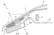
(4h)上記実施形態では、換気ファン17はカバー16の底面に配置されたが、換気ファン17のカバー16における配置位置はこれに限られない。例えば、カバー16の側面に貫通孔を形成し、当該貫通孔にはめ込まれるように換気ファン17が配置されてもよい。また、上記実施形態では、換気ファン17はカバー16に形成された貫通孔にはめ込まれるように配置されたが、換気ファン17の配置方法はこれに限られない。例えば、換気ファンは、図7に示されるように配置されてもよい。すなわち、図7に示すカメラ装置20では、図1に示すカメラ装置1の場合と比較して、カバー16の代わりにカバー201が使用され、換気ファン17が異なった位置に配置されている。
(4h) In the above embodiment, the
カバー201は、容器部位201a及び突出壁201bを備える。容器部位201aは、上方が開放された、側壁及び底壁を有する容器状の部位である。突出壁201bは、容器部位201aの上方の端の一部にて当該容器部位201aの側壁に垂直に当該容器部位201aの外部へ伸びる壁部である。突出壁201bは、画像センサ11、ブラケット12及びフード13がカバー201により下方から覆われた状態において画像センサ11等よりもカメラモジュール111の撮像方向の後方に位置する。図7においては、自車両の天井21と、自車両の天井21を車室側(下側)から覆う天井カバー22と、の間に空間が形成されている。突出壁201bの先端は、天井カバー22の端とつながっており、そのため、自車両の天井21と天井カバー22との間の空間とカバー201の内部の空間とがつながり、両空間の間の空気の通り道が確保される。換気ファン17は、自車両の天井21と天井カバー22との間の空間に配置され、カバー201の内部の空気を入れ換える。
The
(4i)上記実施形態では、換気部として換気ファン17を例示したが、換気部はこれに限られない。例えば、図7に示すカメラ装置20において換気ファン17を排し、天井21と天井カバー22との間の空間に配置されたエアコンダクト内の空気がカバー201内に流入するようにし、自車両に設置されたエアコンの換気ファンを換気部としてもよい。
(4i) In the above embodiment, the
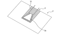
(4j)上記実施形態では、熱線18は、そのS字状部位18aが黒セラミック3の欠損部3aに重ねられるように配置されたが、熱線18の配置方法はこれに限られない。例えば、図8に示すように、熱線18は、黒セラミック3の欠損部3aを囲むように配置されてもよい。また、上記実施形態では、加熱部として熱線18を例示したが、加熱部はこれに限られない。例えば、加熱部は、ヒータであってもよい。
(4j) In the above-described embodiment, the
(4k)上記実施形態では、カメラ装置1は換気ファン17及び熱線18を備えていたが、カメラ装置は換気ファン17及び熱線18のいずれか一方のみを備えていてもよい。また、カメラ装置は、換気ファン17及び熱線18のいずれも備えていなくてもよい。
(4k) In the above embodiment, the
(4l)上記実施形態では、カメラ装置1は単眼カメラであったが、カメラ装置はこれらに限られない。例えば、図9に示すように、カメラ装置はステレオカメラであってもよい。図9に示す車両は、検出部23を備え、検出部23は、車載カメラ231及びレーダ装置52を備える。図9におけるレーダ装置52は、図5におけるレーダ装置52と同一の装置である。車載カメラ231は、右側方カメラ511、左側方カメラ512、後方カメラ513、カメラモジュール111及びカメラモジュール116を備える。つまり、図9に示す車両は、カメラモジュール116を更に備える点で、図5に示す車両と相違する。カメラモジュール116はカメラモジュール111と同一構成の装置であり、カメラモジュール111及びカメラモジュール116は1つの筐体内に収容される。当該筐体はブラケットを介してフロントガラスの上部における中央(ルームミラーの近く)に設置され、カメラモジュール111及びカメラモジュール116はフロントガラスの中心を挟む両側に配置される。なお、図9に示す例では、カメラモジュール111及びカメラモジュー
ル116は1つの筐体内に収容されたが、カメラモジュール111及びカメラモジュール116は2つの筐体に別個に収容されてもよい。また、カメラモジュール111及びカメラモジュール116は、フロントガラスの上部であってフロントガラスの中心を挟む両側に配置されたが、カメラモジュール111及びカメラモジュール116の配置位置はこれに限られない。
(4l) In the above embodiment, the
(4m)上記実施形態では、レーダ装置52はカメラモジュール111の動作が停止している期間に作動したが、レーダ装置52の作動する期間はこれに限られない。例えば、レーダ装置52及びカメラモジュール111が同時に作動してもよい。この場合、認識部9は、カメラモジュール111による撮像画像及びレーダ装置52による検出結果の両方に基づき認識処理を実行してもよい。
(4m) In the above embodiment, the
(4n)上記実施形態では、第1の認識処理と第2の認識処理とは、カメラモジュール111の温度がしきい値Thを超過する、及び、カメラモジュール111の視界が遮られている、のいずれかの条件が成立した場合に切り替わった。しかし、第1の認識処理と第2の認識処理とが切り替わるための条件はこれらに限られない。例えば、カメラモジュール111が故障した場合において第1の認識処理と第2の認識処理とが切り替わってもよい。
(4n) In the above embodiment, the first recognition process and the second recognition process are such that the temperature of the
(4o)上記実施形態では、切替処理は、第1の認識処理と第2の認識処理とが一度切り替わると終了したが、第1の認識処理及び第2の認識処理は複数回切り替わってもよい。例えば、カメラモジュール111の温度がしきい値Thを超過して第1の認識処理が第2の認識処理へ切り替わった場合、カメラモジュール111の温度がしきい値Thよりも低い所定のしきい値以下になると第2の認識処理が第1の認識処理へ切り替わってもよい。この場合、第1の熱伝導部材14及び第2の熱伝導部材15による冷却効果のため、カメラ装置1が早く冷却され、第2の認識処理が第1の認識処理へ切り替わるまでの時間(第1の認識処理が再開されるまでの時間)を短縮することができる。
(4o) In the above embodiment, the switching process ends when the first recognition process and the second recognition process are switched once. However, the first recognition process and the second recognition process may be switched a plurality of times. . For example, when the temperature of the
(4p)上記実施形態では、カメラ装置1及びレーダ装置52により自車両の前方の状況を検出したが、自車両の前方の状況を検出する装置の組合せはこれに限られない。例えば、カメラ装置1及びソナーにより自車両の前方の状況を検出してもよい。
(4p) In the above embodiment, the
(4q)上記実施形態では、認識部9は、第1の認識処理及び第2の認識処理の両方を実行可能であったが、認識部9は第1の認識処理のみ実行可能であってもよい。この場合、自車両は、当該自車両の前方の状況を検出する装置としてカメラ装置1のみを備えていてもよい。
(4q) In the above embodiment, the
(4r)上記実施形態における1つの構成要素が有する機能を複数の構成要素として分散させたり、複数の構成要素が有する機能を1つの構成要素に統合させたりしてもよい。また、上記実施形態の構成の少なくとも一部を、同様の機能を有する公知の構成に置き換えてもよい。また、上記実施形態の構成の一部を省略してもよい。また、上記実施形態の構成の少なくとも一部を、他の上記実施形態の構成に対して付加又は置換してもよい。なお、特許請求の範囲に記載した文言のみによって特定される技術思想に含まれるあらゆる態様が本発明の実施形態である。 (4r) The functions of one component in the above embodiment may be distributed as a plurality of components, or the functions of a plurality of components may be integrated into one component. Further, at least a part of the configuration of the above embodiment may be replaced with a known configuration having the same function. Moreover, you may abbreviate | omit a part of structure of the said embodiment. In addition, at least a part of the configuration of the above embodiment may be added to or replaced with the configuration of the other embodiment. In addition, all the aspects included in the technical idea specified only by the wording described in the claim are embodiment of this invention.
1,20…カメラ装置、2…フロントガラス、11…画像センサ、12…ブラケット、13…フード、14…第1の熱伝導部材、15…第2の熱伝導部材、16,201…カバー、111,116…カメラモジュール、111a…レンズ、111b…レンズ鏡筒部、112…電気接続配線、113…制御回路基板、114…筐体、115…下部カバー。
DESCRIPTION OF
Claims (11)
前記車両の前方の状況を認識する認識処理を前記カメラモジュールによる撮像画像に基づき実行し、車線逸脱警報処理、ヘッドライト制御処理及び前方衝突回避処理のうち少なくとも2つの車両制御処理を前記認識処理の認識結果に基づき実行する、制御回路基板(113)と、
前記カメラモジュール及び前記制御回路基板を収容する筐体(114)と、
前記筐体を前記車両のフロントガラスに固定するための部材であって、前記筐体が当該部材を介して前記フロントガラスに固定された状態において前記筐体と前記フロントガラスとを対向させる開口部が形成されたブラケット(12)と、
前記カメラモジュールを覆うように配置されるフード(13)と、
前記ブラケットに形成された前記開口部において前記筐体と前記フロントガラスとに接するように設けられた第1の熱伝導部材(14)と、
を備え、
前記筐体は、前記ブラケットを介して前記フロントガラスに固定された状態において前記カメラモジュールよりも前記フロントガラス側に位置するガラス側壁部(1141)を備え、
前記ガラス側壁部には、前記カメラモジュールを前記フロントガラス側に露出させるための切欠部(1142)が形成されており、
前記ガラス側壁部は、前記筐体が前記ブラケットを介して前記フロントガラスに固定された状態において前記開口部を介して前記フロントガラスと対向し、
前記第1の熱伝導部材は、前記開口部において前記ガラス側壁部と前記フロントガラスとに接するように設けられていることを特徴とする車載カメラ装置(1,20)。 A camera module (111, 116) for imaging the front of the vehicle;
A recognition process for recognizing a situation ahead of the vehicle is executed based on an image captured by the camera module, and at least two vehicle control processes among a lane departure warning process, a headlight control process, and a front collision avoidance process are performed in the recognition process. A control circuit board (113) to be executed based on the recognition result;
A housing (114) for housing the camera module and the control circuit board;
A member for fixing the casing to the windshield of the vehicle, wherein the casing and the windshield face each other in a state where the casing is fixed to the windshield via the member. A bracket (12) formed with
A hood (13) arranged to cover the camera module;
A first heat conducting member (14) provided in contact with the casing and the windshield at the opening formed in the bracket;
Equipped with a,
The housing includes a glass side wall portion (1141) positioned closer to the windshield than the camera module in a state of being fixed to the windshield via the bracket,
The glass side wall is formed with a notch (1142) for exposing the camera module to the windshield side,
The glass side wall portion faces the windshield through the opening in a state where the housing is fixed to the windshield via the bracket,
The on-vehicle camera device (1, 20), wherein the first heat conducting member is provided in contact with the glass side wall and the windshield at the opening .
前記第1の熱伝導部材は、前記ガラス側壁部における前記切欠部よりも前記カメラモジュールの撮像方向の後方に位置する領域(1141a)に接するように設けられていることを特徴とする車載カメラ装置。 The in-vehicle camera device according to claim 1 ,
The in-vehicle camera device, wherein the first heat conducting member is provided so as to be in contact with a region (1141a) located rearward in the imaging direction of the camera module with respect to the notch portion in the glass side wall portion. .
前記第1の熱伝導部材は、前記ガラス側壁部における前記切欠部を挟む両側の領域(1141b)に接するように設けられていることを特徴とする車載カメラ装置。 The in-vehicle camera device according to claim 1 or 2 ,
The in-vehicle camera device, wherein the first heat conducting member is provided so as to be in contact with regions (1141b) on both sides of the glass sidewall portion sandwiching the notch portion.
前記第1の熱伝導部材の熱伝導率は、1[W/m・K]以上50[W/m・K]以下であることを特徴とする車載カメラ装置。 The in-vehicle camera device according to any one of claims 1 to 3 ,
The in-vehicle camera device characterized in that the thermal conductivity of the first heat conducting member is 1 [W / m · K] or more and 50 [W / m · K] or less.
前記ブラケットと前記フロントガラスとの間に位置し、前記ブラケットと前記フロントガラスとに接するように設けられた第2の熱伝導部材(15)を更に備えることを特徴とする車載カメラ装置。 The in-vehicle camera device according to any one of claims 1 to 4 ,
The in-vehicle camera device further comprising a second heat conducting member (15) located between the bracket and the windshield and provided so as to contact the bracket and the windshield.
前記第2の熱伝導部材の熱伝導率は、1[W/m・K]以上50[W/m・K]以下であることを特徴とする車載カメラ装置。 The in-vehicle camera device according to claim 5 ,
The in-vehicle camera device characterized in that the thermal conductivity of the second heat conducting member is not less than 1 [W / m · K] and not more than 50 [W / m · K].
前記筐体、前記ブラケット及び前記フードを覆うカバー(16,201)と、
前記カバーの内部に存在する空気を入れ換える換気部(17)と、
を更に備えることを特徴とする車載カメラ装置。 It is a vehicle-mounted camera apparatus of any one of Claims 1 thru | or 6 , Comprising:
A cover (16, 201) covering the housing, the bracket and the hood;
A ventilation part (17) for replacing the air present in the cover;
An in-vehicle camera device further comprising:
前記フロントガラスにおける前記カメラモジュールのレンズの前方に位置する部分を加熱する加熱部(18)を更に備えることを特徴とする車載カメラ装置。 It is a vehicle-mounted camera apparatus of any one of Claims 1 thru | or 7 , Comprising:
The in-vehicle camera device further comprising a heating unit (18) for heating a portion of the windshield positioned in front of the lens of the camera module.
前記制御回路基板は、
車線、道路形状、路面状態、光源、先行車両、対向車両、静止車両、先行歩行者、対向歩行者、静止者、自動二輪車、自転車、障害物、路側物、標識、交通信号、道路標示、看板、トンネル、退避領域、前記カメラモジュールの視界を遮るもの、気象環境及び建造物のうち少なくとも1つを前記認識処理で認識し、
車線逸脱警報処理、車線維持処理、ヘッドライト制御処理、出会頭衝突回避処理、交差点衝突回避処理、前方衝突回避処理、標識表示処理、制限速度表示処理、制限速度超過警報処理、オートワイパ処理、車線変更支援処理、アラウンドビュー表示処理、自動駐車処理、全車速アダプティブクルーズコントロール処理、ブラインドスポット警報処理、後方クロストラフィック警報処理、前方クロストラフィック警報処理、車間警報処理、追突警報処理及び誤発進防止処理のうち少なくとも3つの前記車両制御処理を実行することを特徴とする車載カメラ装置。 The vehicle-mounted camera device according to any one of claims 1 to 8 ,
The control circuit board is
Lane, road shape, road surface condition, light source, preceding vehicle, oncoming vehicle, stationary vehicle, preceding pedestrian, oncoming pedestrian, stationary person, motorcycle, bicycle, obstacle, roadside, sign, traffic signal, road marking, signboard Recognizing at least one of a tunnel, a retreat area, an object that obstructs the field of view of the camera module, a weather environment, and a building by the recognition process,
Lane departure warning processing, lane maintenance processing, headlight control processing, head-on collision avoidance processing, intersection collision avoidance processing, forward collision avoidance processing, sign display processing, speed limit display processing, speed limit excess warning processing, auto wiper processing, lane change Support processing, around view display processing, automatic parking processing, full vehicle speed adaptive cruise control processing, blind spot warning processing, rear cross traffic warning processing, forward cross traffic warning processing, inter-vehicle warning processing, rear-end collision warning processing and false start prevention processing An on-vehicle camera device that executes at least three vehicle control processes.
前記カメラモジュールはステレオカメラであることを特徴とする車載カメラ装置(20)。 It is a vehicle-mounted camera apparatus of any one of Claims 1 thru | or 9 , Comprising:
The on-vehicle camera device (20), wherein the camera module is a stereo camera.
前記カメラモジュールの温度を検出する温度センサと、
前記車両の前方に向けて送信信号を放射し、前記車両の前方の物体で反射された前記送信信号を受信信号として受信するとともに、前記送信信号と前記受信信号とから前記物体を検出するレーダ装置(52)と、を更に備え、
前記制御回路基板は、前記認識処理として、前記カメラモジュールによる前記撮像画像に基づく第1の認識処理と、前記レーダ装置による検出結果に基づく第2の認識処理と、を実行可能であり、
前記制御回路基板は、
前記温度センサから前記カメラモジュールの温度を取得する取得部と、
前記取得部により取得された前記カメラモジュールの温度に基づき、前記カメラモジュールの温度が所定のしきい値以下であるか否かを判定する第1の判定部と、
前記第1の認識処理による認識結果に基づき、前記カメラモジュールの視界が遮られているか否かを判定する第2の判定部と、
前記第1の判定部により前記カメラモジュールの温度が前記所定のしきい値以下でないと判定された場合、又は、前記第2の判定部により前記カメラモジュールの視界が遮られていると判定された場合に、前記第1の認識処理を前記第2の認識処理へ切り替える切替え部と、
を備えることを特徴とする車載システム。 An in-vehicle system comprising the in-vehicle camera device according to any one of claims 1 to 10 ,
A temperature sensor for detecting the temperature of the camera module;
A radar device that radiates a transmission signal toward the front of the vehicle, receives the transmission signal reflected by an object in front of the vehicle as a reception signal, and detects the object from the transmission signal and the reception signal (52) and
The control circuit board can execute a first recognition process based on the captured image by the camera module and a second recognition process based on a detection result by the radar device as the recognition process,
The control circuit board is
An acquisition unit for acquiring the temperature of the camera module from the temperature sensor;
A first determination unit that determines whether the temperature of the camera module is equal to or lower than a predetermined threshold based on the temperature of the camera module acquired by the acquisition unit;
A second determination unit that determines whether or not the field of view of the camera module is obstructed based on a recognition result by the first recognition process;
When the first determination unit determines that the temperature of the camera module is not less than or equal to the predetermined threshold, or the second determination unit determines that the field of view of the camera module is blocked when, with the switches switching unit first recognition processing to the second recognition process,
Vehicle system, characterized in that it comprises a.
Priority Applications (4)
| Application Number | Priority Date | Filing Date | Title |
|---|---|---|---|
| JP2014215644A JP6303974B2 (en) | 2014-10-22 | 2014-10-22 | In-vehicle camera device and in-vehicle system |
| US14/918,301 US9961240B2 (en) | 2014-10-22 | 2015-10-20 | In-vehicle camera device and in-vehicle system |
| CN201510683426.6A CN105539310B (en) | 2014-10-22 | 2015-10-20 | Vehicle-mounted camera device and vehicle-mounted system |
| DE102015220575.4A DE102015220575B4 (en) | 2014-10-22 | 2015-10-21 | VEHICLE SIDE CAMERA DEVICE AND VEHICLE SIDE SYSTEM |
Applications Claiming Priority (1)
| Application Number | Priority Date | Filing Date | Title |
|---|---|---|---|
| JP2014215644A JP6303974B2 (en) | 2014-10-22 | 2014-10-22 | In-vehicle camera device and in-vehicle system |
Publications (2)
| Publication Number | Publication Date |
|---|---|
| JP2016078807A JP2016078807A (en) | 2016-05-16 |
| JP6303974B2 true JP6303974B2 (en) | 2018-04-04 |
Family
ID=55698728
Family Applications (1)
| Application Number | Title | Priority Date | Filing Date |
|---|---|---|---|
| JP2014215644A Active JP6303974B2 (en) | 2014-10-22 | 2014-10-22 | In-vehicle camera device and in-vehicle system |
Country Status (4)
| Country | Link |
|---|---|
| US (1) | US9961240B2 (en) |
| JP (1) | JP6303974B2 (en) |
| CN (1) | CN105539310B (en) |
| DE (1) | DE102015220575B4 (en) |
Cited By (1)
| Publication number | Priority date | Publication date | Assignee | Title |
|---|---|---|---|---|
| US12109950B2 (en) | 2020-02-18 | 2024-10-08 | Tokyo Cosmos Electric Co., Ltd. | Attachment device |
Families Citing this family (77)
| Publication number | Priority date | Publication date | Assignee | Title |
|---|---|---|---|---|
| WO2013131700A1 (en) * | 2012-03-05 | 2013-09-12 | Saint-Gobain Glass France | Pane arrangement having an electrically heatable baffle plate |
| US10289921B2 (en) * | 2014-03-24 | 2019-05-14 | Panasonic Automotive Systems Company Of America, Division Of Panasonic Corporation Of North America | Method of operating an in-vehicle camera |
| CN106457965A (en) * | 2014-06-11 | 2017-02-22 | Trw汽车美国有限责任公司 | Moderation of a driver assist camera environment by cooling fan |
| DE112015002727B4 (en) * | 2014-06-11 | 2025-01-09 | Trw Automotive U.S. Llc | Air conditioning of an environment of a driver assistance camera through an air duct of a roof liner |
| US9692862B2 (en) * | 2014-10-23 | 2017-06-27 | Samsung Electronics Co., Ltd. | Camera device and wearable electronic device having the same |
| JP6612271B2 (en) * | 2015-02-13 | 2019-11-27 | 日本板硝子株式会社 | Windshield |
| US9896022B1 (en) | 2015-04-20 | 2018-02-20 | Ambarella, Inc. | Automatic beam-shaping using an on-car camera system |
| JP6390512B2 (en) * | 2015-05-21 | 2018-09-19 | 株式会社デンソー | In-vehicle camera device |
| JP6493087B2 (en) | 2015-08-24 | 2019-04-03 | 株式会社デンソー | In-vehicle camera device |
| WO2017163584A1 (en) * | 2016-03-23 | 2017-09-28 | 日立オートモティブシステムズ株式会社 | Vehicle-mounted image processing device |
| US20170274832A1 (en) * | 2016-03-24 | 2017-09-28 | Nidec Elesys Corporation | Windshield including vehicle-mounted radar |
| EP3226027B8 (en) * | 2016-03-30 | 2019-01-09 | Aptiv Technologies Limited | Radar with defrost beam being absorbed in the radome |
| JP6589726B2 (en) * | 2016-04-06 | 2019-10-16 | トヨタ自動車株式会社 | Vehicle shooting device |
| JP2017206080A (en) * | 2016-05-17 | 2017-11-24 | トヨタ自動車株式会社 | Car camera |
| JP6555190B2 (en) * | 2016-05-18 | 2019-08-07 | トヨタ自動車株式会社 | Vehicle shooting device |
| JP6713832B2 (en) * | 2016-05-26 | 2020-06-24 | 日本板硝子株式会社 | Windshield |
| JP2017214059A (en) * | 2016-05-27 | 2017-12-07 | 日本板硝子株式会社 | Windshield |
| JP6633974B2 (en) * | 2016-06-02 | 2020-01-22 | 日本板硝子株式会社 | Windshield |
| JP6565806B2 (en) * | 2016-06-28 | 2019-08-28 | 株式会社デンソー | Camera system |
| JP6673072B2 (en) * | 2016-07-19 | 2020-03-25 | 株式会社デンソー | Vehicle camera device |
| JP6767186B2 (en) * | 2016-07-20 | 2020-10-14 | 日野自動車株式会社 | In-vehicle camera device |
| FR3054171B1 (en) * | 2016-07-25 | 2021-11-19 | Peugeot Citroen Automobiles Sa | ANTI-GLARE SHOOTING SYSTEM |
| CN106043150B (en) * | 2016-08-04 | 2018-02-09 | 歌尔科技有限公司 | A kind of vehicle-mounted optical projection system with speech identifying function |
| JP2018042141A (en) * | 2016-09-08 | 2018-03-15 | 株式会社デンソー | Imaging device |
| US10288986B2 (en) * | 2017-02-22 | 2019-05-14 | Trw Automotive U.S. Llc | Moderation of a driver assist camera enhancement via a vehicle windshield |
| JP6998661B2 (en) * | 2017-02-22 | 2022-02-10 | 日本板硝子株式会社 | Rear glass |
| JP6699593B2 (en) * | 2017-02-27 | 2020-05-27 | トヨタ自動車株式会社 | Glass heating equipment |
| US10488738B2 (en) * | 2017-03-08 | 2019-11-26 | Trw Automotive U.S. Llc | Temperature management of a driver assist camera via a vehicle windshield |
| JP6678124B2 (en) * | 2017-03-28 | 2020-04-08 | 日立オートモティブシステムズ株式会社 | In-vehicle imaging device |
| DE102017207024B4 (en) | 2017-04-26 | 2023-03-30 | Audi Ag | Sensor arrangement for a motor vehicle and motor vehicle |
| CN108944765A (en) * | 2017-05-19 | 2018-12-07 | 郭宇铮 | A kind of dual camera real-time early warning car crass system |
| JP6813431B2 (en) * | 2017-05-23 | 2021-01-13 | 東京コスモス電機株式会社 | Heat generator |
| DE102017211331A1 (en) * | 2017-07-04 | 2019-01-10 | Robert Bosch Gmbh | Image analysis with targeted preprocessing |
| JP6939353B2 (en) * | 2017-09-29 | 2021-09-22 | 株式会社デンソー | In-vehicle camera device |
| JP6852655B2 (en) * | 2017-11-14 | 2021-03-31 | トヨタ自動車株式会社 | Vehicle measuring device |
| WO2019108964A1 (en) * | 2017-12-01 | 2019-06-06 | Illinois Tool Works Inc. | Lane departure warning system |
| JP6885315B2 (en) * | 2017-12-06 | 2021-06-09 | トヨタ自動車株式会社 | Sensor mounting structure |
| JP7125261B2 (en) * | 2017-12-12 | 2022-08-24 | 小島プレス工業株式会社 | camera for vehicle |
| CN107832759A (en) * | 2017-12-12 | 2018-03-23 | 成都电科海立科技有限公司 | A kind of vehicle-mounted face identification device |
| JP7006258B2 (en) * | 2017-12-27 | 2022-01-24 | トヨタ自動車株式会社 | Vehicle photography equipment and heating equipment |
| US10647173B2 (en) | 2018-01-08 | 2020-05-12 | Ford Global Technologies, Llc | Vehicle sensor temperature control |
| US20190212174A1 (en) * | 2018-01-10 | 2019-07-11 | Ford Global Technologies, Llc | Sensor temperature regulation |
| JP6622332B2 (en) * | 2018-02-13 | 2019-12-18 | 株式会社Subaru | Outside monitoring device |
| US10812712B2 (en) | 2018-04-23 | 2020-10-20 | Toyota Motor Engineering & Manufacturing North America, Inc. | Systems and methods for vehicle camera view activation |
| CN112585036B (en) * | 2018-08-30 | 2024-04-26 | 三菱电机株式会社 | Car camera device |
| JP2020037342A (en) * | 2018-09-05 | 2020-03-12 | 三菱電機株式会社 | On-vehicle camera device |
| CN109493642B (en) * | 2018-10-24 | 2024-04-02 | 魔门塔(苏州)科技有限公司 | Vehicle-mounted shooting device with anti-collision early warning function |
| DE102018218940A1 (en) * | 2018-11-07 | 2020-05-07 | Conti Temic Microelectronic Gmbh | Sensor covering device and motor vehicle with such a sensor covering device |
| JPWO2020116205A1 (en) * | 2018-12-07 | 2021-10-21 | ソニーセミコンダクタソリューションズ株式会社 | Information processing equipment, information processing methods, and programs |
| JP7172682B2 (en) * | 2019-02-06 | 2022-11-16 | トヨタ自動車株式会社 | Camera mounting structure |
| EP3696644B1 (en) * | 2019-02-15 | 2022-06-08 | Veoneer Sweden AB | A cooling arrangement for a motor vehicle |
| JP7078578B2 (en) * | 2019-06-10 | 2022-05-31 | 本田技研工業株式会社 | Transportation equipment and vehicles |
| DE102019122190B4 (en) | 2019-08-19 | 2022-08-11 | Webasto SE | Roof module for forming a vehicle roof with a cooling device |
| WO2021040055A1 (en) | 2019-09-01 | 2021-03-04 | 日本板硝子株式会社 | Windshield |
| US10981520B1 (en) | 2019-11-14 | 2021-04-20 | Zf Friedrichshafen Ag | Driver assist system for a vehicle |
| JP7639696B2 (en) * | 2019-12-06 | 2025-03-05 | Agc株式会社 | Vehicle glass and camera unit |
| US11816905B2 (en) * | 2020-03-19 | 2023-11-14 | Magna Electronics Inc. | Multi-camera vision system integrated into interior rearview mirror |
| JP7624693B2 (en) * | 2020-03-31 | 2025-01-31 | 株式会社ユピテル | In-vehicle equipment, electronic devices and mounting parts, etc. |
| DE102020109505B4 (en) * | 2020-04-06 | 2023-02-16 | Webasto SE | Roof module for forming a vehicle roof |
| JP2020115467A (en) * | 2020-04-08 | 2020-07-30 | 日本板硝子株式会社 | Windshield |
| JP2023523349A (en) * | 2020-04-28 | 2023-06-02 | バヤー イメージング リミテッド | Systems and methods for monitoring a vehicle passenger compartment |
| JP7546382B2 (en) * | 2020-06-02 | 2024-09-06 | 株式会社Subaru | Vehicle-mounted camera device |
| JP7449177B2 (en) | 2020-06-12 | 2024-03-13 | 株式会社Subaru | In-vehicle camera device |
| JP7369677B2 (en) * | 2020-07-22 | 2023-10-26 | 株式会社ニフコ | Heating device for imaging equipment |
| US11474417B2 (en) | 2020-08-07 | 2022-10-18 | Lineage Logistics, LLC | Lens heater assembly for camera |
| JP7445563B2 (en) * | 2020-09-02 | 2024-03-07 | 株式会社ニフコ | Fixation device |
| DE102020129731B4 (en) | 2020-11-11 | 2023-08-17 | Dr. Ing. H.C. F. Porsche Aktiengesellschaft | camera body |
| US11997371B2 (en) * | 2021-01-22 | 2024-05-28 | Magna Electronics Inc. | Vehicular cooling system for forward camera module |
| JP7540377B2 (en) * | 2021-03-23 | 2024-08-27 | Agc株式会社 | Window glass for vehicles with on-board cameras |
| JP7650723B2 (en) * | 2021-05-21 | 2025-03-25 | 小島プレス工業株式会社 | Heater fixing structure for vehicle-mounted camera |
| JP2023006653A (en) * | 2021-06-30 | 2023-01-18 | 日本板硝子株式会社 | Vehicular glass module |
| JP7716315B2 (en) * | 2021-11-05 | 2025-07-31 | ルネサスエレクトロニクス株式会社 | Collision avoidance system and vehicle equipped with same |
| CN114407792B (en) * | 2022-02-21 | 2023-06-23 | 岚图汽车科技有限公司 | Corner radar headlight combination structure and bracket assembly |
| US11833972B1 (en) * | 2022-05-13 | 2023-12-05 | Magna Mirrors Holding Gmbh | Vehicle overhead console with cooling fan |
| US20240155214A1 (en) * | 2022-11-09 | 2024-05-09 | Magna Electronics Inc. | Vehicular camera assembly with thermally conductive adhesive interface |
| US12475679B2 (en) * | 2023-04-04 | 2025-11-18 | Bendix Commercial Vehicle Systems Llc | System and method for optical detection of driver tampering of a camera in a vehicle |
| DE102024120165A1 (en) * | 2024-07-15 | 2026-01-15 | Bayerische Motoren Werke Aktiengesellschaft | Camera arrangement for a vehicle and method for operating a camera arrangement |
Family Cites Families (37)
| Publication number | Priority date | Publication date | Assignee | Title |
|---|---|---|---|---|
| JP2920653B2 (en) | 1990-03-15 | 1999-07-19 | アイシン精機株式会社 | In-vehicle imaging device |
| JP3146016B2 (en) | 1991-03-14 | 2001-03-12 | 株式会社東芝 | Vehicle back confirmation device |
| DE4332836C1 (en) | 1993-09-27 | 1994-09-15 | Daimler Benz Ag | Device for steering a vehicle with controlled tracking |
| JP3684522B2 (en) | 1997-08-22 | 2005-08-17 | 靖正 山口 | Electronic camera that captures images through glass |
| US6170955B1 (en) | 1998-02-27 | 2001-01-09 | Iteris, Inc. | Vehicle mounted optical assembly |
| JP3877475B2 (en) | 1999-09-22 | 2007-02-07 | 富士重工業株式会社 | In-vehicle camera mounting structure |
| JP3148749B1 (en) | 1999-09-22 | 2001-03-26 | 富士重工業株式会社 | In-vehicle camera |
| JP2002341432A (en) * | 2001-05-16 | 2002-11-27 | Murakami Corp | Imaging device |
| JP2002374441A (en) | 2001-06-13 | 2002-12-26 | Mitsubishi Electric Corp | Vehicle window sensor |
| US6882287B2 (en) * | 2001-07-31 | 2005-04-19 | Donnelly Corporation | Automotive lane change aid |
| JP2003300414A (en) | 2002-04-11 | 2003-10-21 | Mitsubishi Electric Corp | In-vehicle equipment |
| JP4045871B2 (en) * | 2002-06-21 | 2008-02-13 | トヨタ自動車株式会社 | Camera cover for on-board camera |
| DE10237608A1 (en) | 2002-08-16 | 2004-02-26 | Hella Kg Hueck & Co. | Camera arrangement for motor vehicles |
| JP2004112329A (en) * | 2002-09-18 | 2004-04-08 | Toyota Motor Corp | Imaging system |
| DE10319176A1 (en) * | 2003-04-29 | 2004-11-18 | Robert Bosch Gmbh | Device for cooling a camera |
| SE526424C2 (en) | 2003-06-02 | 2005-09-13 | Lear Corp | Active night vision system for an internal passenger compartment of a vehicle and method for controlling said system |
| DE10329900A1 (en) | 2003-07-03 | 2005-02-17 | Daimlerchrysler Ag | Camera system for a motor vehicle |
| GB0408392D0 (en) | 2004-04-15 | 2004-05-19 | Pilkington Plc | Electrically heated window |
| JP2005341522A (en) | 2004-04-27 | 2005-12-08 | Kyocera Corp | Camera module, in-vehicle camera device using the same, and manufacturing method thereof |
| DE102004024735A1 (en) | 2004-05-19 | 2005-12-15 | Leopold Kostal Gmbh & Co Kg | Camera arrangement for a motor vehicle |
| JP5005535B2 (en) * | 2005-06-25 | 2012-08-22 | 株式会社堀場製作所 | Driving recorder |
| EP1914691A4 (en) | 2005-07-01 | 2011-11-02 | Japan Automobile Res Inst | DRIVING RECORDER |
| JP2007011908A (en) | 2005-07-01 | 2007-01-18 | Japan Automobile Research Inst Inc | Driving recorder |
| JP4754284B2 (en) * | 2005-07-05 | 2011-08-24 | 富士重工業株式会社 | Thermal insulation structure for in-vehicle equipment |
| CN101535087B (en) * | 2005-11-01 | 2013-05-15 | 唐纳利公司 | Interior rearview mirror with display |
| JP4871663B2 (en) | 2006-07-21 | 2012-02-08 | 株式会社堀場製作所 | Mounting tool for vehicle-mounted driving recorder |
| DE102007035027A1 (en) | 2007-07-26 | 2009-01-29 | Adc Automotive Distance Control Systems Gmbh | Viewing window for arranging an optical sensor and / or recognition system in a vehicle |
| JP4849346B2 (en) | 2008-09-08 | 2012-01-11 | トヨタ自動車株式会社 | Road section mark recognition device and lane departure prevention device |
| US8570374B2 (en) * | 2008-11-13 | 2013-10-29 | Magna Electronics Inc. | Camera for vehicle |
| DE102009026319A1 (en) | 2009-08-04 | 2011-02-24 | Saint-Gobain Sekurit Deutschland Gmbh & Co. Kg | Disc with optically transparent sensor field |
| JP5472078B2 (en) * | 2010-12-21 | 2014-04-16 | 株式会社デンソー | Car camera |
| DE102011103302A1 (en) * | 2011-06-03 | 2012-12-06 | Conti Temic Microelectronic Gmbh | Camera system for a vehicle |
| CN103717392B (en) | 2011-08-05 | 2016-02-03 | 三菱工程塑料株式会社 | Panels and Panel Settings Structure |
| JP2013053966A (en) * | 2011-09-05 | 2013-03-21 | Nikon Corp | Observation device |
| JP5206898B2 (en) | 2011-10-17 | 2013-06-12 | 三菱エンジニアリングプラスチックス株式会社 | panel |
| JP5761100B2 (en) * | 2012-03-28 | 2015-08-12 | 株式会社デンソー | Car camera |
| JP5949490B2 (en) * | 2012-11-20 | 2016-07-06 | トヨタ自動車株式会社 | Vehicle sensor mounting structure and system linkage method |
-
2014
- 2014-10-22 JP JP2014215644A patent/JP6303974B2/en active Active
-
2015
- 2015-10-20 CN CN201510683426.6A patent/CN105539310B/en active Active
- 2015-10-20 US US14/918,301 patent/US9961240B2/en active Active
- 2015-10-21 DE DE102015220575.4A patent/DE102015220575B4/en active Active
Cited By (1)
| Publication number | Priority date | Publication date | Assignee | Title |
|---|---|---|---|---|
| US12109950B2 (en) | 2020-02-18 | 2024-10-08 | Tokyo Cosmos Electric Co., Ltd. | Attachment device |
Also Published As
| Publication number | Publication date |
|---|---|
| DE102015220575B4 (en) | 2021-09-02 |
| US9961240B2 (en) | 2018-05-01 |
| DE102015220575A1 (en) | 2016-04-28 |
| US20160119509A1 (en) | 2016-04-28 |
| JP2016078807A (en) | 2016-05-16 |
| CN105539310A (en) | 2016-05-04 |
| CN105539310B (en) | 2022-10-28 |
Similar Documents
| Publication | Publication Date | Title |
|---|---|---|
| JP6303974B2 (en) | In-vehicle camera device and in-vehicle system | |
| US10880459B2 (en) | Optical device and imaging device with mechanism for reducing condensation | |
| JP6519355B2 (en) | Camera apparatus and in-vehicle system | |
| JP6493087B2 (en) | In-vehicle camera device | |
| CN107547784B (en) | Camera system | |
| US10479274B2 (en) | Vehicle and control method for the same | |
| KR100935737B1 (en) | Danger recognition system for vehicles, comprising at least one lateral and rear environment detection unit | |
| CN111204333B (en) | Vehicle forward blind spot detection and warning system | |
| CN103874931B (en) | For the method and apparatus of the position of the object in the environment for asking for vehicle | |
| WO2019181112A1 (en) | Imaging system and vehicle window for use in same | |
| CN113401120A (en) | Driving assistance system, method for operating driving assistance system, and program product | |
| JP2004331021A (en) | Night obstacle notification device | |
| WO2020218498A1 (en) | Sensing system and vehicle | |
| CN113492754B (en) | Driving environment detection system of commercial vehicle, cab of commercial vehicle and commercial vehicle | |
| JP2021187367A (en) | Vehicle control method, vehicle control program and vehicle control system | |
| KR20230106207A (en) | Vehicle and method for performing according to at least one mode | |
| JP6699593B2 (en) | Glass heating equipment | |
| EP3276588B1 (en) | Cross traffic detection system for a vehicle |
Legal Events
| Date | Code | Title | Description |
|---|---|---|---|
| A621 | Written request for application examination |
Free format text: JAPANESE INTERMEDIATE CODE: A621 Effective date: 20160915 |
|
| A977 | Report on retrieval |
Free format text: JAPANESE INTERMEDIATE CODE: A971007 Effective date: 20170607 |
|
| A131 | Notification of reasons for refusal |
Free format text: JAPANESE INTERMEDIATE CODE: A131 Effective date: 20170718 |
|
| A521 | Request for written amendment filed |
Free format text: JAPANESE INTERMEDIATE CODE: A523 Effective date: 20170914 |
|
| TRDD | Decision of grant or rejection written | ||
| A01 | Written decision to grant a patent or to grant a registration (utility model) |
Free format text: JAPANESE INTERMEDIATE CODE: A01 Effective date: 20180206 |
|
| A61 | First payment of annual fees (during grant procedure) |
Free format text: JAPANESE INTERMEDIATE CODE: A61 Effective date: 20180219 |
|
| R151 | Written notification of patent or utility model registration |
Ref document number: 6303974 Country of ref document: JP Free format text: JAPANESE INTERMEDIATE CODE: R151 |
|
| R250 | Receipt of annual fees |
Free format text: JAPANESE INTERMEDIATE CODE: R250 |
|
| R250 | Receipt of annual fees |
Free format text: JAPANESE INTERMEDIATE CODE: R250 |
|
| R250 | Receipt of annual fees |
Free format text: JAPANESE INTERMEDIATE CODE: R250 |
|
| R250 | Receipt of annual fees |
Free format text: JAPANESE INTERMEDIATE CODE: R250 |
|
| R250 | Receipt of annual fees |
Free format text: JAPANESE INTERMEDIATE CODE: R250 |
|
| R250 | Receipt of annual fees |
Free format text: JAPANESE INTERMEDIATE CODE: R250 |