JP6272214B2 - Container sterilization method and sterilization system - Google Patents
Container sterilization method and sterilization system Download PDFInfo
- Publication number
- JP6272214B2 JP6272214B2 JP2014244055A JP2014244055A JP6272214B2 JP 6272214 B2 JP6272214 B2 JP 6272214B2 JP 2014244055 A JP2014244055 A JP 2014244055A JP 2014244055 A JP2014244055 A JP 2014244055A JP 6272214 B2 JP6272214 B2 JP 6272214B2
- Authority
- JP
- Japan
- Prior art keywords
- container
- sterilization
- ozone gas
- wet
- wet ozone
- Prior art date
- Legal status (The legal status is an assumption and is not a legal conclusion. Google has not performed a legal analysis and makes no representation as to the accuracy of the status listed.)
- Active
Links
Images



Classifications
-
- A—HUMAN NECESSITIES
- A61—MEDICAL OR VETERINARY SCIENCE; HYGIENE
- A61L—METHODS OR APPARATUS FOR STERILISING MATERIALS OR OBJECTS IN GENERAL; DISINFECTION, STERILISATION OR DEODORISATION OF AIR; CHEMICAL ASPECTS OF BANDAGES, DRESSINGS, ABSORBENT PADS OR SURGICAL ARTICLES; MATERIALS FOR BANDAGES, DRESSINGS, ABSORBENT PADS OR SURGICAL ARTICLES
- A61L2/00—Disinfection or sterilisation of materials or objects, in general; Accessories therefor
- A61L2/16—Disinfection or sterilisation of materials or objects, in general; Accessories therefor using chemical substances
- A61L2/20—Gaseous substances, e.g. vapours
- A61L2/202—Ozone
-
- A—HUMAN NECESSITIES
- A61—MEDICAL OR VETERINARY SCIENCE; HYGIENE
- A61L—METHODS OR APPARATUS FOR STERILISING MATERIALS OR OBJECTS IN GENERAL; DISINFECTION, STERILISATION OR DEODORISATION OF AIR; CHEMICAL ASPECTS OF BANDAGES, DRESSINGS, ABSORBENT PADS OR SURGICAL ARTICLES; MATERIALS FOR BANDAGES, DRESSINGS, ABSORBENT PADS OR SURGICAL ARTICLES
- A61L2/00—Disinfection or sterilisation of materials or objects, in general; Accessories therefor
- A61L2/16—Disinfection or sterilisation of materials or objects, in general; Accessories therefor using chemical substances
- A61L2/20—Gaseous substances, e.g. vapours
-
- A—HUMAN NECESSITIES
- A61—MEDICAL OR VETERINARY SCIENCE; HYGIENE
- A61L—METHODS OR APPARATUS FOR STERILISING MATERIALS OR OBJECTS IN GENERAL; DISINFECTION, STERILISATION OR DEODORISATION OF AIR; CHEMICAL ASPECTS OF BANDAGES, DRESSINGS, ABSORBENT PADS OR SURGICAL ARTICLES; MATERIALS FOR BANDAGES, DRESSINGS, ABSORBENT PADS OR SURGICAL ARTICLES
- A61L2/00—Disinfection or sterilisation of materials or objects, in general; Accessories therefor
- A61L2/24—Apparatus using programmed or automatic operation
-
- B—PERFORMING OPERATIONS; TRANSPORTING
- B29—WORKING OF PLASTICS; WORKING OF SUBSTANCES IN A PLASTIC STATE IN GENERAL
- B29C—SHAPING OR JOINING OF PLASTICS; SHAPING OF MATERIAL IN A PLASTIC STATE, NOT OTHERWISE PROVIDED FOR; AFTER-TREATMENT OF THE SHAPED PRODUCTS, e.g. REPAIRING
- B29C49/00—Blow-moulding, i.e. blowing a preform or parison to a desired shape within a mould; Apparatus therefor
- B29C49/42—Component parts, details or accessories; Auxiliary operations
- B29C49/46—Component parts, details or accessories; Auxiliary operations characterised by using particular environment or blow fluids other than air
-
- B—PERFORMING OPERATIONS; TRANSPORTING
- B65—CONVEYING; PACKING; STORING; HANDLING THIN OR FILAMENTARY MATERIAL
- B65B—MACHINES, APPARATUS OR DEVICES FOR, OR METHODS OF, PACKAGING ARTICLES OR MATERIALS; UNPACKING
- B65B55/00—Preserving, protecting or purifying packages or package contents in association with packaging
- B65B55/02—Sterilising, e.g. of complete packages
- B65B55/027—Packaging in aseptic chambers
-
- B—PERFORMING OPERATIONS; TRANSPORTING
- B65—CONVEYING; PACKING; STORING; HANDLING THIN OR FILAMENTARY MATERIAL
- B65B—MACHINES, APPARATUS OR DEVICES FOR, OR METHODS OF, PACKAGING ARTICLES OR MATERIALS; UNPACKING
- B65B55/00—Preserving, protecting or purifying packages or package contents in association with packaging
- B65B55/02—Sterilising, e.g. of complete packages
- B65B55/04—Sterilising wrappers or receptacles prior to, or during, packaging
-
- B—PERFORMING OPERATIONS; TRANSPORTING
- B65—CONVEYING; PACKING; STORING; HANDLING THIN OR FILAMENTARY MATERIAL
- B65B—MACHINES, APPARATUS OR DEVICES FOR, OR METHODS OF, PACKAGING ARTICLES OR MATERIALS; UNPACKING
- B65B55/00—Preserving, protecting or purifying packages or package contents in association with packaging
- B65B55/02—Sterilising, e.g. of complete packages
- B65B55/04—Sterilising wrappers or receptacles prior to, or during, packaging
- B65B55/10—Sterilising wrappers or receptacles prior to, or during, packaging by liquids or gases
-
- A—HUMAN NECESSITIES
- A61—MEDICAL OR VETERINARY SCIENCE; HYGIENE
- A61L—METHODS OR APPARATUS FOR STERILISING MATERIALS OR OBJECTS IN GENERAL; DISINFECTION, STERILISATION OR DEODORISATION OF AIR; CHEMICAL ASPECTS OF BANDAGES, DRESSINGS, ABSORBENT PADS OR SURGICAL ARTICLES; MATERIALS FOR BANDAGES, DRESSINGS, ABSORBENT PADS OR SURGICAL ARTICLES
- A61L2202/00—Aspects relating to methods or apparatus for disinfecting or sterilising materials or objects
- A61L2202/10—Apparatus features
- A61L2202/14—Means for controlling sterilisation processes, data processing, presentation and storage means, e.g. sensors, controllers, programs
-
- A—HUMAN NECESSITIES
- A61—MEDICAL OR VETERINARY SCIENCE; HYGIENE
- A61L—METHODS OR APPARATUS FOR STERILISING MATERIALS OR OBJECTS IN GENERAL; DISINFECTION, STERILISATION OR DEODORISATION OF AIR; CHEMICAL ASPECTS OF BANDAGES, DRESSINGS, ABSORBENT PADS OR SURGICAL ARTICLES; MATERIALS FOR BANDAGES, DRESSINGS, ABSORBENT PADS OR SURGICAL ARTICLES
- A61L2202/00—Aspects relating to methods or apparatus for disinfecting or sterilising materials or objects
- A61L2202/10—Apparatus features
- A61L2202/16—Mobile applications, e.g. portable devices, trailers, devices mounted on vehicles
-
- B—PERFORMING OPERATIONS; TRANSPORTING
- B65—CONVEYING; PACKING; STORING; HANDLING THIN OR FILAMENTARY MATERIAL
- B65B—MACHINES, APPARATUS OR DEVICES FOR, OR METHODS OF, PACKAGING ARTICLES OR MATERIALS; UNPACKING
- B65B3/00—Packaging plastic material, semiliquids, liquids or mixed solids and liquids, in individual containers or receptacles, e.g. bags, sacks, boxes, cartons, cans, or jars
- B65B3/02—Machines characterised by the incorporation of means for making the containers or receptacles
- B65B3/022—Making containers by moulding of a thermoplastic material
-
- B—PERFORMING OPERATIONS; TRANSPORTING
- B67—OPENING, CLOSING OR CLEANING BOTTLES, JARS OR SIMILAR CONTAINERS; LIQUID HANDLING
- B67C—CLEANING, FILLING WITH LIQUIDS OR SEMILIQUIDS, OR EMPTYING, OF BOTTLES, JARS, CANS, CASKS, BARRELS, OR SIMILAR CONTAINERS, NOT OTHERWISE PROVIDED FOR; FUNNELS
- B67C7/00—Concurrent cleaning, filling, and closing of bottles; Processes or devices for at least two of these operations
Landscapes
- Engineering & Computer Science (AREA)
- Mechanical Engineering (AREA)
- Health & Medical Sciences (AREA)
- Animal Behavior & Ethology (AREA)
- Epidemiology (AREA)
- Life Sciences & Earth Sciences (AREA)
- General Health & Medical Sciences (AREA)
- Public Health (AREA)
- Veterinary Medicine (AREA)
- Manufacturing & Machinery (AREA)
- Chemical & Material Sciences (AREA)
- Chemical Kinetics & Catalysis (AREA)
- General Chemical & Material Sciences (AREA)
- Apparatus For Disinfection Or Sterilisation (AREA)
Description
本発明は、例えば飲料水などの液体を充填する容器の殺菌方法に関する。 The present invention relates to a method of sterilizing a container for filling a liquid such as drinking water.
飲料水などの液体をPET(Polyethyleneterephthalate)ボトルやガラス瓶、ボトル
缶等の容器に充填するシステムとして、回転式の充填装置が用いられている。この回転式の充填装置は、回転体の外周部に複数の充填バルブを備えており、回転体がほぼ1回転して容器が周方向に搬送される間に、充填バルブから容器内への充填を行う。そして、容器への充填が終了した後、キャッパや打栓機により容器への蓋の装着が行われる。
上記の容器の中で、PETボトルは、プリフォームと呼ばれる試験管状の前駆体に空気を吹き込んで成形される。この成形には、主に二軸延伸ブロー成形法が用いられている。二軸延伸ブロー成形法とは、加熱したプリフォームを金型に挿入後、延伸ロッドと呼ばれる棒で垂直方向に引き伸ばしながら、加圧空気を吹き込んで円周方向に膨らませる成形法である。ちなみに、プリフォームの成形方法としては、インジェクション(射出)成形法、PCM(Preform Compression Molding)成形法の2種類が知られている。
PETボトルを対象とする飲料充填システムは、PETボトルの成形装置を上流側に備え、成形されたPETボトルを充填装置に供給する形態もあれば、すでに成形されたPETボトルを用意して充填装置に供給する形態もある。
As a system for filling a container such as a PET (Polyethyleneterephthalate) bottle, a glass bottle, or a bottle can with a liquid such as drinking water, a rotary filling device is used. This rotary filling device is provided with a plurality of filling valves on the outer periphery of the rotating body, and the filling from the filling valve into the container is carried out while the rotating body rotates almost once and the container is conveyed in the circumferential direction. I do. Then, after filling the container, the lid is attached to the container by a capper or a stopper.
Among the above-described containers, the PET bottle is formed by blowing air into a test tubular precursor called a preform. For this molding, a biaxial stretch blow molding method is mainly used. The biaxial stretch blow molding method is a molding method in which a heated preform is inserted into a mold and then expanded in the circumferential direction by blowing pressurized air while being stretched in a vertical direction with a rod called a stretch rod. Incidentally, two types of preform molding methods are known: an injection (injection) molding method and a PCM (Preform Compression Molding) molding method.
A beverage filling system for PET bottles has a PET bottle molding device on the upstream side, and there is a form in which the molded PET bottle is supplied to the filling device. There is also a form to supply to.
ところで、飲料水などの液体を充填する場合、雑菌が容器に混入するのを限りなく防ぐことが必要であり、このため、クリーンルーム内で、容器殺菌・すすぎ、キャップ殺菌、液体の充填及びキャップ装着といった一連の工程を行ういわゆる無菌充填方式が採用されている。PETボトルの成形装置を上流側に備える飲料充填システムの場合には、この成形装置で成形されたPETボトルを殺菌して充填装置に供給することが要求されることもある。
無菌充填方式における殺菌としては、薬剤、例えば、過酢酸(PAA)、過酸化水素(H2O2)を含む水溶液からなる過酢酸系殺菌剤が用いられている(例えば、特許文献1,2)。
By the way, when filling liquids such as drinking water, it is necessary to prevent contamination of bacteria in the container as much as possible. For this reason, in a clean room, container sterilization / rinsing, cap sterilization, liquid filling and cap attachment A so-called aseptic filling method that performs such a series of processes is employed. In the case of a beverage filling system equipped with a PET bottle molding device on the upstream side, it may be required to sterilize a PET bottle molded by this molding device and supply it to the filling device.
As the sterilization in the aseptic filling method, a peracetic acid-based disinfectant comprising an aqueous solution containing a drug, for example, peracetic acid (PAA) or hydrogen peroxide (H 2 O 2 ) is used (for example,
ところが、過酢酸を殺菌剤として用いる場合は、過酢酸に対する耐性菌が作り出されることが問題となっている。また、過酸化水素については、耐性菌の問題はないものの、PETボトルを対象とする場合には、PETに吸収されて、容器に残留してしまうという問題がある。
そこで本発明は、この課題を解消し、液状の薬剤を用いない、新しい容器の殺菌方法を提供することを目的とする。
However, when peracetic acid is used as a bactericidal agent, the problem is that resistant bacteria against peracetic acid are created. In addition, hydrogen peroxide has no problem of resistant bacteria, but when PET bottles are targeted, there is a problem that it is absorbed by PET and remains in the container.
Therefore, an object of the present invention is to solve this problem and to provide a new container sterilization method that does not use a liquid medicine.
本発明者らは、飲料充填システムにおける容器の殺菌にオゾン(O3)を用いることを検討したところ、連続的に搬送される容器に湿度を含むオゾンガス(以下「湿潤オゾンガス」)を供給することにより、要求される殺菌能力を達成できることを知見した。
本発明の容器の殺菌方法は、この知見に基づくものであり、所定の搬送路を連続的に搬送される複数の容器に、殺菌成分を供給して殺菌する方法であって、湿度を含むオゾンガスである湿潤オゾンガスを、搬送路を含むチャンバにより区画される殺菌領域に供給する、ことを特徴とする。
The present inventors examined using ozone (O 3 ) for sterilization of containers in a beverage filling system, and supplied ozone gas containing humidity (hereinafter “wet ozone gas”) to containers that are continuously transported. Thus, it was found that the required sterilizing ability can be achieved.
The container sterilization method of the present invention is based on this finding, and is a method of supplying a sterilizing component to a plurality of containers that are continuously transported through a predetermined transport path to sterilize the ozone gas including humidity. The wet ozone gas is supplied to a sterilization region defined by a chamber including a conveyance path.
本発明の殺菌方法において、殺菌領域に供給される湿潤オゾンガスは、殺菌領域に搬送される容器よりも温度が高いことが好ましい。
これにより、湿潤オゾンガスを容器の表面に結露させて、高い殺菌性能を確保することができる。
In the sterilization method of the present invention, the wet ozone gas supplied to the sterilization region preferably has a higher temperature than the container transported to the sterilization region.
Thereby, wet ozone gas can be condensed on the surface of the container, and high sterilization performance can be ensured.
本発明の殺菌方法において、チャンバは、殺菌領域に搬送される容器よりも温度が高いことが好ましい。
これにより、湿潤オゾンガスがチャンバにではなく、容器に結露しやすくなる。
In the sterilization method of the present invention, the temperature of the chamber is preferably higher than that of the container transported to the sterilization region.
This makes it easier for the wet ozone gas to condense on the container, not on the chamber.
本発明の殺菌方法において、殺菌領域に供給される湿潤オゾンガスを、殺菌領域に搬送される容器の温度に応じて、その湿度が調整されることが好ましい。
これにより、湿潤オゾンガスが容器の表面に結露されるのを確保できる。
In the sterilization method of the present invention, it is preferable that the humidity of the wet ozone gas supplied to the sterilization region is adjusted according to the temperature of the container transported to the sterilization region.
Thereby, it can be ensured that the wet ozone gas is condensed on the surface of the container.
本発明の殺菌方法において、殺菌領域に供給される容器は、殺菌領域に供給される湿潤オゾンガスの湿度に応じて、その温度が調整されることが好ましい。
これによっても、湿潤オゾンガスを容器の表面に結露されるのを確保できる。
In the sterilization method of the present invention, the temperature of the container supplied to the sterilization area is preferably adjusted according to the humidity of the wet ozone gas supplied to the sterilization area.
This also ensures that the wet ozone gas is condensed on the surface of the container.
本発明の殺菌方法において、殺菌領域に供給される湿潤オゾンガスは、湿潤オゾンガスよりも湿度の低いオゾンガスと水分を接触させることにより生成させることが好ましい。
これにより、任意の湿度の湿潤オゾンガスを生成させることができる。
In the sterilization method of the present invention, the wet ozone gas supplied to the sterilization area, it is preferable to produce by than wet ozone gas contacting the low ion Zongasu and moisture humidity.
Thereby, the wet ozone gas of arbitrary humidity can be produced | generated.
本発明の殺菌方法において、殺菌領域に供給される湿潤オゾンガスを、容器の内部に導入すると、容器の内周面を殺菌することができる。 In the sterilization method of the present invention, when the wet ozone gas supplied to the sterilization region is introduced into the container, the inner peripheral surface of the container can be sterilized.
本発明の殺菌方法において、殺菌領域に供給される湿潤オゾンガスを、容器の周囲に供給すると容器の外周面を殺菌し、かつ、容器の内部を減圧することにより周囲から内部に吸引されて容器の内周面を殺菌することができる。 In the sterilization method of the present invention, when the wet ozone gas supplied to the sterilization region is supplied to the periphery of the container, the outer peripheral surface of the container is sterilized, and the inside of the container is decompressed to be sucked from the surroundings to the inside. The inner peripheral surface can be sterilized.
また、本発明の容器の殺菌システムは、複数の容器を連続的に搬送する搬送路と、搬送路上に設けられ、搬送路を含むチャンバにより区画される殺菌領域と、殺菌領域に供給される、湿度を含むオゾンガスである殺菌成分としての湿潤オゾンガスを生成する湿潤ガス生成部と、を備えることを特徴とする。 Moreover, the container sterilization system of the present invention is supplied to a sterilization area, a sterilization area that is provided on the conveyance path, and is partitioned by a chamber that includes the conveyance path, and a sterilization area . A wet gas generating unit that generates wet ozone gas as a sterilizing component that is ozone gas containing humidity .
本発明の殺菌システムにおいて、湿潤ガス生成部は、殺菌領域に搬送される容器よりも高い温度の、湿潤オゾンガスを生成することが好ましい。 In the sterilization system of the present invention, it is preferable that the wet gas generation unit generates wet ozone gas having a temperature higher than that of the container transported to the sterilization region.
本発明の殺菌システムにおいて、チャンバは、殺菌領域に搬送される容器よりも温度が高くされていることが好ましい。 In the sterilization system of the present invention, the temperature of the chamber is preferably higher than that of the container transported to the sterilization region.
本発明の殺菌システムにおいて、湿潤ガス生成部は、湿潤オゾンガスよりも湿度の低いオゾンガスと水分を接触させることにより、湿潤オゾンガスを生成することが好ましい。なお、この水分は、液体及び気体のいずれの状態をも含む。 In the sterilization system of the present invention, it is preferable that the wet gas generation unit generates wet ozone gas by bringing the ozone gas having a lower humidity than the wet ozone gas into contact with moisture. This moisture includes both liquid and gas states.
本発明の殺菌システムにおいて、湿潤ガス生成部は、殺菌領域に搬送される容器の温度に応じて湿潤オゾンガスの湿度を調整して、湿潤オゾンガスを生成することが好ましい。 In the sterilization system of the present invention, it is preferable that the wet gas generation unit adjusts the humidity of the wet ozone gas according to the temperature of the container transported to the sterilization region to generate the wet ozone gas.
本発明の殺菌システムにおいて、殺菌領域に供給される湿潤オゾンガスの湿度に応じて、殺菌領域に供給される容器の温度を調整する温度調整器を備えることが好ましい。 In the sterilization system of the present invention, it is preferable to include a temperature regulator that adjusts the temperature of the container supplied to the sterilization region in accordance with the humidity of the wet ozone gas supplied to the sterilization region.
本発明の殺菌システムにおいて、殺菌領域を搬送される容器の内部に挿入され、湿潤オゾンガスを容器の内部に供給する手段を備えることが好ましい。 In the sterilization system of the present invention, it is preferable that the sterilization system includes means for supplying wet ozone gas to the inside of the container that is inserted into the container that is transported through the sterilization region.
本発明の殺菌システムにおいて、殺菌領域を搬送される容器の内部を減圧する減圧手段と、湿潤オゾンガスを容器の周囲に供給する手段と、を備える、ことが好ましい。 In the sterilization system of the present invention, it is preferable that the sterilization system includes decompression means for decompressing the inside of the container conveyed through the sterilization region, and means for supplying wet ozone gas around the container.
本発明によれば、殺菌に湿潤オゾンガスを用いるが、このオゾンガスは耐性菌を作らないし、また、容器が例えばPETから構成される場合に、容器に残留することがない。しかも、本発明によると、搬送路を含むチャンバにより区画された殺菌領域を設けることにより、外部へのオゾンの漏洩を防止することができる。さらに、湿潤オゾンガスを用いることにより、飲料用の容器に要求される殺菌性能を十分に得ることができる。 According to the present invention, wet ozone gas is used for sterilization, but this ozone gas does not form resistant bacteria, and when the container is made of, for example, PET, it does not remain in the container. In addition, according to the present invention, ozone leakage to the outside can be prevented by providing the sterilization region partitioned by the chamber including the conveyance path. Further, by using the wet ozone gas, it is possible to obtain a disinfection performance required for the container for the beverage sufficiently.
以下、添付図面に示す実施の形態に基づいてこの発明を詳細に説明する。
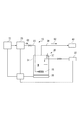
図1に示すように、本実施形態に係る飲料用容器の殺菌システム1は、湿潤オゾンガスを生成する湿潤ガス生成部10と、湿潤ガス生成部10で生成された湿潤オゾンガスを導入し、かつ、搬送される飲料用の容器Pに供給することで容器Pを殺菌する殺菌部40と、湿潤ガス生成部10と殺菌部40の動作を司る制御部70と、を備える。湿潤ガス生成部10と殺菌部40は、無菌室2の内部に設けられている。
Hereinafter, the present invention will be described in detail based on embodiments shown in the accompanying drawings.
As shown in FIG. 1, the beverage
[湿潤ガス生成部10]
湿潤ガス生成部10は、図2に示すように、ドライ状態のオゾン(O3)を生成し、かつ、生成したオゾンを湿潤化装置30に送るオゾン生成装置20と、送られてきたドライ状態のオゾンを湿潤化させる湿潤化装置30と、を備え、いわゆるバブリング方式により湿潤オゾンガスG2を生成させる。湿潤化装置30で湿潤化されたオゾンガスは殺菌部40に送られる。
[Wet gas generator 10]
As shown in FIG. 2, the wet
オゾン生成装置20は、原料供給源21から供給される酸素(O2)ガスを原料としてオゾンと酸素の混合ガスG1を生成する。この混合ガスにおけるオゾンの濃度は、例えば、5〜15体積%程度、典型的には10体積%とする。なお、酸素に限らず、原料として酸素を含むガス、例えば空気を用いることもできる。
The
オゾン生成方式には無声放電方式、電気分解方式、紫外線ランプ方式等がある。工業的用途には無声放電方式が用いられており、本実施形態においても無声放電方式を適用することが好ましいが、他の方式を採用することを妨げない。ここで、無声放電(Silent discharge)とは、平行電極間に誘電体(dielectric)を設け、この間に酸素ガスを供給し、両極間に交流高電圧を印加する際に観察される放電現象である。この無声放電により気体中に電子eが放出される。この電子eを安定な酸素分子O2に衝突させて、酸素分子O2を酸素原子Oに解離させる第1ステップと、酸素原子Oと酸素分子O2と第三の物質M(例えば、窒素分子)を含めた三体衝突が生ずる第2ステップにより、オゾンが生成する。混合ガスには、第三の物質Mも含まれる。
第1ステップ:O2+e→2O+e
第2ステップ:O+O2+M→O3+M
The ozone generation method includes a silent discharge method, an electrolysis method, an ultraviolet lamp method, and the like. The silent discharge method is used for industrial applications, and it is preferable to apply the silent discharge method also in this embodiment, but it does not prevent other methods from being adopted. Here, silent discharge is a discharge phenomenon observed when a dielectric is provided between parallel electrodes, oxygen gas is supplied therebetween, and an alternating high voltage is applied between the two electrodes. . Electrons e are emitted into the gas by this silent discharge. A first step of causing the electrons e to collide with stable oxygen molecules O 2 to dissociate the oxygen molecules O 2 into oxygen atoms O; an oxygen atom O, an oxygen molecule O 2, and a third substance M (for example, a nitrogen molecule) Ozone is generated by the second step in which a three-body collision including) occurs. The mixed gas includes the third substance M.
First step: O 2 + e → 2O + e
Second step: O + O 2 + M → O 3 + M
オゾン生成装置20で生成させたドライ状態の混合ガスG1は、第1配管23を介して湿潤化装置30に供給される。第1配管23の先端には、多孔質材から構成されるノズル25が取り付けられており、ノズル25は、湿潤化装置30の水槽31に蓄えられている水Wに浸漬されている。
The dry mixed gas G <b> 1 generated by the
湿潤化装置30は、予め蓄えられている水Wと混合ガスG1とを接触させる水槽31と、水槽31に水Wを供給する水供給源33と、水槽31に蓄えられている水を加熱するヒータ35と、水槽31の内部であって、水Wよりも上方の空間領域の温度を測定する第1温度センサ37と、生成された湿潤オゾンガスG2を殺菌部40に向けて供給する第2配管39と、を備えている。なお、湿潤オゾンガスG2は、これまでの説明から明らかなように、O3(オゾン)以外に、第三の物質M及び湿度を含んでいる。
The wetting
水槽31に蓄えられている水Wに浸漬されているノズル25から吐出されるオゾン混合ガスG1は微細な気泡となって水Wの中を浮上し、この浮上の過程で水Wと接触することにより、湿潤オゾンガスG2となって、水Wの表面から放出される。放出された湿潤オゾンガスG2は、水槽31の空隙領域及び第2配管39を順に通って、殺菌部40に供給される。湿潤オゾンガスG2の主たる構成要素は、酸素(O2)、オゾン(O 3)及び水(H2 O)である。
The ozone mixed gas G1 discharged from the
水槽31に蓄えられる水Wは、ヒータ35により、60〜100℃の範囲、典型的には80℃に加熱されるので、水Wの表面から放出される湿潤オゾンガスG2も、水Wの加熱温度とほぼ等しい温度に制御されて殺菌部40に供給される。
Since the water W stored in the
湿潤オゾンガスG2は、殺菌部40を搬送される容器Pの温度における相対湿度RHが、45〜100%の範囲であることが好ましい。これは、湿潤オゾンガスG2の相対湿度RHが45%以上で十分な殺菌能力が得られるからであり、逆に、湿潤オゾンガスG2の相対湿度RHが100%を超えると殺菌能力が劣るからである。より好ましい相対湿度RHは80〜100%、さらに好ましい相対湿度RHは95〜100%である。
ここでいう相対湿度RHは、殺菌部40を搬送される容器Pの温度における相対湿度RHであり、湿潤化装置30で湿潤オゾンガスG2が生成された時点の相対湿度とは異なる。換言すると、湿潤化装置30で生成される湿潤オゾンガスG2は、殺菌対象であり、湿潤オゾンガスG2が供給される容器Pの温度を考慮して、その相対湿度RHが調整されるべきである。この点については、さらに後述する。
The wet ozone gas G2 preferably has a relative humidity RH in the range of 45 to 100% at the temperature of the container P transported through the
The relative humidity RH here is the relative humidity RH at the temperature of the container P transported through the
[殺菌部40]
殺菌部40は、湿潤ガス生成部10から供給される湿潤オゾンガスG2を、上工程から連続的に搬送される容器Pの内周面及び外周面に作用させて殺菌を行い、殺菌の完了した容器Pを下工程に受け渡す。
[Sterilization part 40]
The
殺菌部40は、図1に示すように、上工程から搬送される容器Pを受け取り、かつ、把持しながら搬送する第1回転テーブル41と、第1回転テーブル41で搬送されてきた容器Pを受け取り、かつ、把持しながら搬送する第2回転テーブル42と、第2回転テーブル42で搬送されてきた容器Pを受け取り、かつ、把持しながら搬送する第3回転テーブル43とを備える。それぞれの回転テーブル41〜43は、図示を省略する電動機により回転可能に構成されている。
それぞれの回転テーブル41〜43は、容器Pのネックを把持しながら容器Pを昇降させることのできる昇降グリッパ46(図4(a)を参照)を備えている。複数の昇降グリッパ46は、それぞれの回転テーブル41〜43の周方向に均等間隔に、かつ、回転テーブル41〜43を貫通するように設けられている。
As shown in FIG. 1, the
Each of the rotary tables 41 to 43 includes an elevating gripper 46 (see FIG. 4A) that can elevate and lower the container P while gripping the neck of the container P. The plurality of lifting
第2回転テーブル42は、図4(a)に示すように、それぞれの昇降グリッパ46に対応して、遮蔽筒47とガス供給ノズル48を備える。
遮蔽筒47は、殺菌処理される容器Pの周囲を覆った状態で、容器Pと遮蔽筒47の間に湿潤オゾンガスG2を滞留させることで、容器Pの外周面の殺菌を加速させる。
遮蔽筒47は、円筒状の形態をなしており、昇降グリッパ46を取り囲むように、軸方向の一方の端部が第2回転テーブル42の下面に固定されている。遮蔽筒47に取り囲まれる昇降グリッパ46は、図4(a)の左側に示すように、最も下降すると遮蔽筒47の先端(下端)から把持部分が露出する。また、昇降グリッパ46は、図4(a)の右側に示すように、最も上昇すると把持部分が第2回転テーブル42の下面の近くまで達して、容器Pの外周面の大部分が遮蔽筒47に覆われる。
As shown in FIG. 4A, the second rotary table 42 includes a
The shielding
The shielding
ガス供給ノズル48は、湿潤ガス生成部10で生成された湿潤オゾンガスG2の供給を受けるとともに、容器Pに向けて吐出する。ガス供給ノズル48と把持される容器Pとは同軸上に配置される。
ガス供給ノズル48は、第2回転テーブル42を厚さ方向に貫通して設けられ、湿潤オゾンガスG2の入口48Aは第2回転テーブル42の上面に開口している。ガス供給ノズル48は、容器Pが最も上昇したときに、入口48Aと逆の端部に設けられる吐出口48Bが、容器Pの底部の近傍に達するように長さが設定される。ガス供給ノズル48は、遮蔽筒47の内部に設けられ、本実施形態では遮蔽筒47と同等の長さを有している。
なお、ガス供給ノズル48は、リンスエリア60においては、リンス用のAirを供給
するノズルとして機能する。
The
The
The
昇降グリッパ46、遮蔽筒47及びガス供給ノズル48は、第2回転テーブル42が回転するのに伴って、回転軸Cを中心に回転運動する。
なお、第1、3回転テーブル41,43は、容器Pを把持しながら回転搬送するだけの単純な構造を有している。
The elevating
The first and
次に、殺菌部40は、図1、図3及び図5(a)〜(f)に示すように、第2回転テーブル42に殺菌エリア50とリンスエリア60を備えている。
Next, as shown in FIGS. 1, 3, and 5 (a) to 5 (f) , the
[殺菌エリア50]
殺菌エリア50は、図3及び図5(a)〜(f)に示すように、第2回転テーブル42の下面に接するように設けられる殺菌チャンバ51とリンスチャンバ61、第2回転テーブル42の上面に接するように設けられるガス溜チャンバ54,56と、を備える。
[Sterilization area 50]
As shown in FIGS. 3 and 5 (a) to 5 (f) , the
殺菌チャンバ51は、横断面がコの字(C字)状をなしており、開口側が上を向いて、第2回転テーブル42の下面に接するように配置される。この殺菌チャンバ51は、第2回転テーブル42に設けられる昇降グリッパ46、遮蔽筒47及びガス供給ノズル48を、内部に収容する。昇降グリッパ46に把持される容器Pは、第2回転テーブル42の回転に伴って、殺菌チャンバ51の内部を上流から下流に向けて移動する。この移動の過程において、容器Pには所定の殺菌処理がなされる。なお、殺菌チャンバ51は、平面視すると、円弧状の形態を有している(図1参照)。ガス溜チャンバ56も同様である。
殺菌チャンバ51は、第2回転テーブル42が回転運動するのとは異なり、位置が固定されている。したがって、殺菌チャンバ51と第2回転テーブル42の接触部分は、第2回転テーブル42の回転運動に伴って摺動する。
The
The position of the
殺菌チャンバ51は、図3に示すように、排気領域52と、殺菌領域53と、を備えている。
As shown in FIG. 3, the
排気領域52は、ガス供給ノズル48から内部に湿潤オゾンガスG2を供給する一方、内部の湿潤オゾンガスG2を含むガスを強制的に排気する領域である。強制的に排気されたガスは所定の排気施設に収容することで、湿潤オゾンガスG2が意図しないところに漏れ出るのを防ぐ。排気領域52は、この目的を達成するために、図5(a),(b)に示すように、殺菌チャンバ51に排出管55を備えている。
殺菌領域53は、主に容器Pの内周面を殺菌処理する領域であり、図5(c)に示すように、容器Pは、内部にガス供給ノズル48が挿入されながら、搬送される。その後、容器Pは、第2回転テーブル42の昇降グリッパ46に把持されながら次のリンスエリア60に向けて搬送される。
The
The
殺菌チャンバ51は、図5(a)〜(c)に示すように、昇降グリッパ46による容器Pの昇降の程度に応じて、容器Pの搬送方向に沿って高さを変動させることができる。つまり、容器Pの受け渡し時には、容器Pを遮蔽筒47の先端から出すために容器Pを昇降させる必要がありその分だけ殺菌チャンバ51の高さを高くする必要があるが、それ以外の領域では、湿潤オゾンガスG2が無駄に供給されるのを避けるために、高さを低くしている。なお、図3には殺菌チャンバ51の高さを一定に描いている。また、リンスチャンバ61も同様である。
As shown in FIGS. 5A to 5C, the
次に、ガス溜チャンバ54は、図3及び図5(a)〜(c)に示すように、横断面がコの字(C字)状をなしており、開口側が下を向いて、第2回転テーブル42の上面に接するように配置される。このガス溜チャンバ54は、昇降グリッパ46と干渉しない位置に設けられる一方、第2回転テーブル42の上面に開口するガス供給ノズル48の入口48Aを覆う位置に設けられる。
ガス溜チャンバ54は、殺菌チャンバ51とは異なり、領域が区切られていることはなく、また、搬送方向の上流から下流に向けて一様な開口面積を有している。
ガス溜チャンバ54は、搬送方向の複数個所に、湿潤オゾンガスG2を内部に導入する導入管57を設けており、それぞれの導入管57には湿潤化装置30の第2配管39が接続される。
ガス溜チャンバ54もまた、第2回転テーブル42が回転運動するのとは異なり、位置が固定されている。したがって、ガス溜チャンバ54と第2回転テーブル42の接触部分は、第2回転テーブルの回転運動に伴って摺動する。
Next, the
Unlike the
The
The position of the
殺菌チャンバ51の最も上流側に位置する排気領域52には、図3に示すように、搬送されてくる容器Pの温度を計測する第2温度センサ58が設けられている。第2温度センサ58が計測した容器Pの温度は、制御部70に送られ、湿潤ガス生成部10において生成される湿潤オゾンガスG2の相対湿度RHの制御及び殺菌チャンバ51の温度管理に用いられる。
また、殺菌チャンバ51には、図3に示すように、面状のヒータ59が設けられており、このヒータ59は第2温度センサ58の計測結果に基づいて、制御部70によって搬送されてくる容器Pよりも高い温度に制御される。
As shown in FIG. 3, a
Further, as shown in FIG. 3, the
[リンスエリア60]
次に、リンスエリア60は、図3及び図5(d)〜(f)に示すように、第2回転テーブル42の下面に接するように設けられるリンスチャンバ61と、第2回転テーブル42を貫通するガス供給ノズル48と、を備える。
リンスチャンバ61は、横断面がコの字(C字)状をなしており、開口側が上を向いて、第2回転テーブル42の下面に接するように配置される。昇降グリッパ46に把持される容器Pは、第2回転テーブル42の回転に伴って、リンスチャンバ61の内部を上流から下流に向けて移動する。この移動の過程において、容器Pは所定のすすぎ処理がなされる。
リンスチャンバ61は、第2回転テーブル42が回転運動するのとは異なり、位置が固定されている。したがって、リンスチャンバ61と第2回転テーブル42の接触部分も、第2回転テーブル42の回転運動に伴って摺動する。
リンスチャンバ61は、殺菌エリア50で供給された湿潤オゾンガスG2及びすすぎ用に吹き込んだエア(Air)を強制的に排気するために、図5(d)〜(f)に示すように、排出管65を備えている。強制的に排気されたガスは所定の排気施設に収容されることで、湿潤オゾンガスG2が意図しないところに漏れ出るのを防ぐ。
[Rinse area 60]
Next, rinse the
The rinse
The rinse
Rinse
次に、ガス溜チャンバ56は、図3及び図5(d)〜(f)に示すように、横断面がコの字(C字)状をなしており、ガス溜チャンバ54と区分されている点、及び、導入管57がすすぎ用のエア(Air)の供給源80(図1参照)に接続されていることを除くと、ガス溜チャンバ54と同じ構成を備えている。
Next, as shown in FIGS. 3 and 5 (d) to (f) , the
[制御部70]
制御部70は、湿潤ガス生成部10及び殺菌部40の動作を司る(図1参照)。特に、本実施形態の制御部70は、湿潤ガス生成部10において生成される湿潤オゾンガスG2の相対湿度RHを制御するとともに、殺菌チャンバ51の温度が搬送されてくる容器Pよりも高温に維持されるようにヒータ59の温度を制御する。
[Control unit 70]
The
湿潤オゾンガスG2による殺菌性能は、殺菌対象物に対する相対湿度RHに左右される。したがって、殺菌対象である容器Pの温度を第2温度センサ58で計測し、制御部70は、この計測結果を取得して、現時点において高い殺菌性能が得られる相対湿度RHを求める。制御部70は、この相対湿度RHを得るために必要なオゾン生成装置20と湿潤化装置30の運転条件を求め、各々に対してこの運転条件で運転されるように指示する。相対湿度RHを高くするためには、水Wに吹き込む混合ガスG1の気泡の粒径を小さくする、吹き込まれた混合ガスG1の気泡が水Wに接触する時間を長くする、ヒータ35による水Wの加熱温度を高くする、あるいは、水槽31の容量を大きくして、混合ガスG1が水Wと接触する面積を増やす、水槽31を大型化して水Wとの接触面積を増やすといった手立てを採用すればよい。
The sterilization performance by the wet ozone gas G2 depends on the relative humidity RH with respect to the sterilization target. Therefore, the temperature of the container P to be sterilized is measured by the
殺菌チャンバ51に供給された湿潤オゾンガスG2を容器Pの殺菌に有効に消費させるためには、殺菌チャンバ51に結露して付着することを避けなければならない。そこで、本実施形態では、第2温度センサ58で計測した容器Pの温度を制御部70が取得し、制御部70は、この計測結果に基づいて、搬送されてくる容器Pよりも殺菌チャンバ51が高温に維持されるようにヒータ59の温度を制御する。
In order to effectively consume the wet ozone gas G <b> 2 supplied to the
[殺菌処理手順]
以下、殺菌システム1を用いて容器Pを殺菌処理する手順を説明する。
上流から連続的に搬送されてきた容器Pは、第1回転テーブル41を介して第2回転テーブル42に受け渡される。第2温度センサ58は、第2回転テーブル42に受け渡された容器Pの温度を計測し、制御部70がその結果を取得する。
第2回転テーブル42に受け渡された容器Pは、第2回転テーブル42の回転動作に伴って、殺菌チャンバ51の排気領域52に搬送される。排気領域52に搬送された容器Pは、図5(a)に示すように、遮蔽筒47よりも下方に位置しているが、搬送が進むにしたがって、図5(b)に示すように、昇降グリッパ46が上昇することにより遮蔽筒47の内部に進入する。排気領域52では、導入管57及びガス溜チャンバ54を通ってきた湿潤オゾンガスG2が、ガス供給ノズル48から容器Pに向けて吐出される。一方で、殺菌チャンバ51の内部は、排出管55を介して外部に排気される。
[Sterilization procedure]
Hereinafter, a procedure for sterilizing the container P using the
The container P that has been continuously conveyed from the upstream is transferred to the second rotary table 42 via the first rotary table 41. The
The container P delivered to the
排気領域52を通過すると、容器Pは殺菌領域53に到達する。
殺菌領域53では、図5(c)に示すように、殺菌チャンバ51の横断面の開口面積が最も狭い領域を容器Pが通過する。
殺菌領域53において、ガス供給ノズル48は容器Pの内部に挿入されているので、ガス供給ノズル48から吐出される湿潤オゾンガスG2は、容器Pの内周面に作用して殺菌処理する。湿潤オゾンガスG2の一部は容器Pから溢れだして、容器Pと遮蔽筒47の間の間隙を漂いながら、容器Pの外周面に作用して、容器Pの外周面を殺菌処理する。容器Pへの湿潤オゾンガスG2の結露を促進するためには、湿潤オゾンガスG2の方が容器Pよりも湿度が高いことが望まれる。なお、容器Pの外周面に直接的に湿潤オゾンガスを供給するためのノズルを設けることもできる。
After passing through the
In the
In the
容器Pの内周面及び外周面に湿潤オゾンガスG2が作用する際には、内周面及び外周面に湿潤オゾンガスG2に基づく結露が生じても構わないし、微細な水滴に分散した状態の結露は殺菌性能の観点から好ましい。しかし、必要以上の結露、例えば、内周面又は外周面に結露水が連続的に一様に膜を形成する程度に濡れてしまうのは好ましくない。容器Pに対する湿潤オゾンガスG2の好ましい作用の状態は、実験的に求めることができる。 When the wet ozone gas G2 acts on the inner peripheral surface and the outer peripheral surface of the container P, dew condensation based on the wet ozone gas G2 may occur on the inner peripheral surface and the outer peripheral surface. It is preferable from the viewpoint of sterilization performance. However, it is not preferable that the dew condensation is more than necessary, for example, that the dew condensation water wets the inner peripheral surface or the outer peripheral surface so as to continuously and uniformly form a film. The preferable state of action of the wet ozone gas G2 on the container P can be obtained experimentally.
殺菌チャンバ51は、制御部70の制御に基づいて、ヒータ59により加熱されているので、供給された湿潤オゾンガスG2は、殺菌チャンバ51に結露することなく、容器Pの殺菌処理に有効に消費される。
Since the
殺菌領域53を通過すると、容器Pはリンスエリア60に達する。図5(d)〜(f)に示すように、リンスエリア60においては、容器Pは昇降グリッパ46に把持されながら、リンスチャンバ61の内部を搬送される。
リンスチャンバ61には、リンス用のエアが、導入管57、ガス溜チャンバ56及びガス供給ノズル48を介して、リンスチャンバ61内の容器Pに吐出される。連続的に供給されるエアは、容器Pの内周面及び外周面に作用して、湿潤オゾンガスG2が容器Pに残留するのを防止する。
リンスチャンバ61には、排出管65が設けられており、リンスチャンバ61の内部の気体は、排出管65を介して外部に排気される。
リンスエリア60を通過した容器Pは第3回転テーブル43に受け渡され、下工程に向けて移送される。
After passing through the
Rinsing air is discharged into the rinsing
The rinse
The container P that has passed through the rinse
[効 果]
以上説明した殺菌システム1が奏する効果を説明する。
殺菌システム1は、殺菌成分として湿潤オゾンガスG2を用いる。
オゾンは耐性菌を作らないし、また、容器PがPETから構成される場合であっても、容器Pに残留することがない。また、液状の薬剤を用いる場合に必要とされる処理設備が不要となる。
しかも、殺菌システム1は、湿潤オゾンガスG2を用いることにより、飲料用の容器Pに要求される殺菌性能を十分に得ることができる。つまり、本発明者らは、湿潤オゾンガスG2を用いた殺菌性能評価を行ったところ、図7に示すように、容器の殺菌性能として十分な殺菌能力D値がえられている。D値は、以下により定義される。
D値=log〔I/(MV)〕
I:初発菌数 MV:殺菌処理後の生菌数
[Effect]
The effect which the
The
Ozone does not produce resistant bacteria and does not remain in the container P even if the container P is made of PET. Moreover, the processing equipment required when using a liquid chemical | medical agent becomes unnecessary .
Moreover, the
D value = log [I / (MV)]
I: Number of initial bacteria MV: Number of live bacteria after sterilization
また、殺菌システム1は、殺菌エリア50に搬入される容器Pの温度に対して最適な相対湿度RHが得られるように、湿潤ガス生成部10の動作を制御するので、湿潤オゾンガスG2の殺菌性能を十分に引き出すことができる。しかも、湿潤オゾンガスG2を容器Pに優先的に作用させるために、殺菌チャンバ51の温度を制御するので、供給される湿潤オゾンガスG2をむだに消費させることなく容器Pの殺菌に用いることができる。さらに、殺菌エリア50において、容器Pの受け渡し動作に対応する昇降に応じて殺菌チャンバ51の高さに制限を設けたので、殺菌に必要な湿潤オゾンガスG2の量を抑えることができるので、殺菌に要するコストの上昇を抑えることができる。
In addition, the
また、殺菌システム1は、殺菌領域53において、遮蔽筒47を設けることにより、供給した湿潤オゾンガスG2をこの遮蔽筒47より内側に集約させることができるので、効率的に容器Pの殺菌を行うことができる。
Moreover, since the
以上、本発明の好適な形態を説明したが、本発明の主旨を逸脱しない限り、上記実施の形態で挙げた構成を取捨選択したり、他の構成に適宜変更したりすることが可能である。以下、いくつかの変更例について説明する。 The preferred embodiments of the present invention have been described above. However, the configurations described in the above embodiments can be selected or changed to other configurations as appropriate without departing from the gist of the present invention. . Hereinafter, some modified examples will be described.
[湿潤化方法]
殺菌システム1においては、湿潤オゾンガスG2を生成するのに、気泡式溶解法の一種であるバブリング法を用いたが、本発明において、湿潤オゾンガスG2を生成する手法は任意である。
例えば、気泡式溶解法の他の方法として知られるエジェクター法を採用することができる。
また、それぞれ生成された湿潤酸素等の湿潤ガスとオゾンガスとを混合する混合法、シャワー状に散布される水にオゾンガスを供給するシャワー法等を採用することができる。
また、任意の方法でオゾン水を生成した後に、これを気化して湿潤オゾンガスG2を生成することもできるし、任意の方法で水蒸気を生成し、これにオゾンガスを接触させることもできる。
[Wetting method]
In the
For example, an ejector method known as another method of the bubble dissolution method can be employed.
In addition, a mixing method in which wet gas such as wet oxygen generated and ozone gas are mixed, a shower method in which ozone gas is supplied to water sprayed in a shower shape, and the like can be employed.
Moreover, after producing | generating ozone water by arbitrary methods, this can be vaporized and the wet ozone gas G2 can also be produced | generated, water vapor | steam can be produced | generated by arbitrary methods, and ozone gas can also be made to contact this.
[相対湿度制御]
殺菌システム1は、容器Pの温度を計測し、それに適合するように、湿潤ガス生成部10で生成する湿潤オゾンガスG2の湿度を調整するが、容器Pに供給する湿潤オゾンガスG2の相対湿度RHを制御する手法はこれに限らない。つまり、本発明は、湿潤化装置30で生成される湿潤オゾンガスG2の湿度を一定としつつ、容器Pの温度を調整することによっても、容器Pに供給する湿潤オゾンガスG2の相対湿度RHを制御することができる。この場合、殺菌エリア50に供給される容器Pの温度を予め計測しておき、必要な相対湿度RHが得られるように、容器Pを冷却又は加熱すればよい。
飲料充填システムにおいて本発明が適用される例として、例えば、容器Pの成形装置の下工程に置かれ、成形されたばかりの容器Pを殺菌する場合がある。この容器Pの成形はプリフォームへの加熱を伴い、成形された容器Pは例えば70℃程度の温度を有しており、湿潤オゾンガスG2の温度、相対湿度RHによっては、容器Pを冷却する必要がある。また、飲料充填システムにおいて本発明が適用される他の例として、すでに成形され、保管されていた容器Pを殺菌する場合がある。この場合には、容器Pの温度は、室温(例えば25℃)程度であるが、湿潤オゾンガスG2の温度、相対湿度RHによっては、容器Pを加熱する必要がある。容器Pの冷却又は加熱を行うには、例えば、冷風又は温風を容器Pに吹き付ければよい。
[Relative humidity control]
The
As an example to which the present invention is applied in a beverage filling system, for example, there is a case where a container P which has been formed and placed in a lower process of the container P molding apparatus is sterilized. The molding of the container P involves heating the preform, and the molded container P has a temperature of about 70 ° C., for example. Depending on the temperature of the wet ozone gas G2 and the relative humidity RH, it is necessary to cool the container P. There is. Moreover, as another example to which the present invention is applied in a beverage filling system, there is a case of sterilizing a container P that has already been molded and stored. In this case, the temperature of the container P is about room temperature (for example, 25 ° C.), but the container P needs to be heated depending on the temperature of the wet ozone gas G2 and the relative humidity RH. In order to cool or heat the container P, for example, cold air or warm air may be blown onto the container P.
[吸引法]
次に、殺菌エリア50において、容器Pに湿潤オゾンガスG2を作用させるのに、湿潤オゾンガスG2を吹き込んでいるが、本発明はこれに限定されない。つまり、本発明は、容器Pの内部を減圧することにより、容器Pの周囲に供給された湿潤オゾンガスG2を容器Pの内部に吸引して、湿潤オゾンガスG2を内周面及び外周面に作用させることができる。この手法を、以下、吸引法と略記する。その一例を、図4(b)及び図6(a)〜(f)を参照して説明する。なお。図4(b)及び図6(a)〜(f)において、図4(a)及び図5(a)〜(f)に示されるのと同じ構成要素については、図4(a)及び図5(a)〜(f)と同じ符号を付けており、以下では、図4(a)及び図5(a)〜(f)との相違点を中心に説明する。
[Suction method]
Next, in the
吸引法に係る本実施形態は、容器Pの内部を減圧するための吸引ノズル49を設けるとともに、湿潤オゾンガスG2を供給するガス供給ノズル48を設ける。吸引ノズル49は、真空ポンプに接続されており、この真空ポンプは制御部70の指示に基づいて作動する。ガス供給ノズル48は、湿潤化装置30の第2配管39に接続されており、湿潤化装置30で生成された湿潤オゾンガスG2が第2配管39及びガス供給ノズル48を介して、殺菌チャンバ51の内部に供給される。ここで、吸引ノズル49は、容器Pが殺菌される所定位置に配置されるときに、容器Pの中心軸と一致する位置に設けられる。また、ガス供給ノズル48は、平面視して、容器Pがこの所定位置に配置されるときに、遮蔽筒47の内側であって、かつ、容器Pの外側に設けられる。
In the present embodiment related to the suction method, a
以下、吸引法における容器Pの殺菌手順を、図6(a)〜(f)を参照して説明する。
上流から連続的に搬送されてきた容器Pは、第1回転テーブル41を介して第2回転テーブル42に受け渡される。第2温度センサ58は、第2回転テーブル42に受け渡された容器Pの温度を計測し、制御部70がその結果を取得する。ここまでは、吹き込み法と同じである。
排気領域52においては、吸引ノズル49を介して、容器Pの内部を減圧するとともに、ガス供給ノズル48から湿潤オゾンガスG2を遮蔽筒47の内部に供給する。また、殺菌チャンバ51の内部は、排出管55を介して外部に排気される(図6(a),(b))。
Hereinafter, the sterilizing procedure a container P in the suction method will be described with reference to FIG. 6 (a) ~ (f) .
The container P that has been continuously conveyed from the upstream is transferred to the second rotary table 42 via the first rotary table 41. The
In the
排気領域52を通過すると、容器Pは殺菌領域53に到達する。
殺菌領域53(図6(c))においては、容器Pの内部が減圧される一方、容器Pの周囲に湿潤オゾンガスG2が供給されるので、湿潤オゾンガスG2は容器Pの外周面に接した後に、容器Pの内部に吸引され、さらに、吸引ノズル49を介して外部に排出される。
After passing through the
In the sterilization region 53 (FIG. 6 (c ) ), the inside of the container P is depressurized, while the wet ozone gas G2 is supplied around the container P, so that the wet ozone gas G2 comes into contact with the outer peripheral surface of the container P. Then, it is sucked into the container P and further discharged to the outside through the
殺菌領域53を通過すると、容器Pはガス溜めチャンバ56に達するが、以降は、リンスエリア60も含めて、吹き込み法と同様である。
After passing through the
吸引法による殺菌処理は、排気領域52において、容器Pの内部の空気が排出されてから、容器Pが殺菌領域53に搬送される。つまり、殺菌領域53に搬送される容器Pの内部は、空気がほとんど残存しておらず、すでに湿潤オゾンガスG2で満たされているので、湿潤オゾンガスG2を効率よく容器Pに作用させることができる。
In the sterilization process by the suction method, the air inside the container P is exhausted in the
これ以外にも、本発明の主旨を逸脱しない限り、上記実施の形態で挙げた構成を取捨選択したり、他の構成に適宜変更したりすることが可能である。 In addition to this, the configuration described in the above embodiment can be selected or changed to another configuration as appropriate without departing from the gist of the present invention.
1 殺菌システム
2 無菌室
10 湿潤ガス生成部
20 オゾン生成装置
21 原料供給源
23 第1配管
25 ノズル
30 湿潤化装置
31 水槽
33 水供給源
35 ヒータ
37 第1温度センサ
39 第2配管
40 殺菌部
41 第1回転テーブル
42 第2回転テーブル
43 第3回転テーブル
46 昇降グリッパ
47 遮蔽筒
48 ガス供給ノズル
48A 入口
48B 吐出口
49 吸引ノズル
50 殺菌エリア
51 殺菌チャンバ
52 排気領域
53 殺菌領域
54 ガス溜チャンバ
55 排出管
56 ガス溜チャンバ
57 導入管
58 第2温度センサ
59 ヒータ
60 リンスエリア
61 リンスチャンバ
65 排出管
70 制御部
80 すすぎ用のエアの供給源
G1 混合ガス
G2 湿潤オゾンガス
P 容器
DESCRIPTION OF
80 rinsing air source
G1 gas mixture
G2 wet ozone gas
P container
Claims (18)
湿度を含むオゾンガスである湿潤オゾンガスを、前記搬送路を含むチャンバにより区画される殺菌領域に供給する、
ことを特徴とする容器の殺菌方法。 A method of supplying a sterilizing component to a container that is continuously transported through a predetermined transport path to sterilize,
Supplying wet ozone gas, which is ozone gas containing humidity, to a sterilization region defined by a chamber including the transfer path;
The container sterilization method characterized by the above-mentioned.
前記殺菌領域に搬送される前記容器よりも温度が高い、
請求項1に記載の容器の殺菌方法。 The wet ozone gas supplied to the sterilization area is
The temperature is higher than the container transported to the sterilization area,
The container sterilization method according to claim 1.
前記殺菌領域に搬送される前記容器よりも温度が高い、
請求項1又は請求項2に記載の容器の殺菌方法。 The chamber is
The temperature is higher than the container transported to the sterilization area,
The method for sterilizing a container according to claim 1 or 2.
前記殺菌領域に搬送される前記容器の温度に応じて、その湿度が調整される、
請求項1〜請求項3のいずれか一項に記載の容器の殺菌方法。 The wet ozone gas supplied to the sterilization area is
The humidity is adjusted according to the temperature of the container conveyed to the sterilization area,
The container sterilization method according to any one of claims 1 to 3.
前記殺菌領域に供給される前記湿潤オゾンガスの湿度に応じて、その温度が調整される、
請求項1〜請求項3のいずれか一項に記載の容器の殺菌方法。 The container supplied to the sterilization area is
The temperature is adjusted according to the humidity of the wet ozone gas supplied to the sterilization region,
The container sterilization method according to any one of claims 1 to 3.
前記湿潤オゾンガスよりも湿度の低いオゾンガスと水分を接触させることにより生成される、
請求項1〜請求項5のいずれか一項に記載の容器の殺菌方法。 The wet ozone gas conveyed to the sterilization area is
Produced by contacting moisture with ozone gas having a lower humidity than the wet ozone gas,
The container sterilization method according to any one of claims 1 to 5.
前記容器の内部に導入されることで前記容器の内周面を殺菌する、
請求項1〜請求項6のいずれか一項に記載の容器の殺菌方法。 The wet ozone gas supplied to the sterilization area is
Sterilizing the inner peripheral surface of the container by being introduced into the container;
The container sterilization method according to any one of claims 1 to 6.
前記容器の周囲に供給されて前記容器の外周面を殺菌し、かつ、前記容器の内部を減圧することにより前記周囲から前記内部に吸引されて前記容器の内周面を殺菌する、
請求項1〜請求項6のいずれか一項に記載の容器の殺菌方法。 The wet ozone gas supplied to the sterilization area is
Sterilizing the outer peripheral surface of the container supplied to the periphery of the container, and sterilizing the inner peripheral surface of the container by being sucked into the interior from the periphery by depressurizing the interior of the container;
The container sterilization method according to any one of claims 1 to 6.
前記搬送路上に設けられ、前記搬送路を含むチャンバにより区画される殺菌領域と、
前記殺菌領域に供給される、湿度を含むオゾンガスである湿潤オゾンガスを生成する湿潤ガス生成部と、
を備えることを特徴とする容器の殺菌システム。 A conveying path to continuously convey a plurality of containers,
A sterilization region provided on the transport path and defined by a chamber including the transport path ;
A wet gas generator that generates wet ozone gas that is ozone gas containing humidity, which is supplied to the sterilization region;
A container sterilization system comprising:
前記殺菌領域に搬送される前記容器よりも高い温度の前記湿潤オゾンガスを生成する、請求項9に記載の容器の殺菌システム。 The wet gas generator is
The container sterilization system according to claim 9 , wherein the wet ozone gas having a temperature higher than that of the container conveyed to the sterilization region is generated.
前記殺菌領域に搬送される前記容器よりも温度が高くされている、
請求項9又は請求項10に記載の容器の殺菌システム。 The chamber is
The temperature is higher than the container transported to the sterilization area,
The container sterilization system according to claim 9 or 10.
前記湿潤オゾンガスよりも湿度の低いオゾンガスと水分を接触させることにより、前記湿潤オゾンガスを生成する、
請求項9〜請求項11のいずれか一項に記載の容器の殺菌システム。 The wet gas generator is
The wet ozone gas is produced by contacting moisture with ozone gas having a humidity lower than that of the wet ozone gas.
The container sterilization system according to any one of claims 9 to 11.
前記殺菌領域に搬送される前記容器の温度に応じて、前記湿潤オゾンガスの湿度を調整する、
請求項9〜請求項12のいずれか一項に記載の容器の殺菌システム。 The wet gas generator is
Adjusting the humidity of the wet ozone gas according to the temperature of the container conveyed to the sterilization region,
The container sterilization system according to any one of claims 9 to 12.
請求項9〜請求項12のいずれか一項に記載の容器の殺菌システム。 In accordance with the humidity of the wet ozone gas supplied to the sterilization region, a temperature adjuster for adjusting the temperature of the container supplied to the sterilization region,
The container sterilization system according to any one of claims 9 to 12.
請求項9〜請求項14のいずれか一項に記載の容器の殺菌システム。 Inserted into the container to be transported through the sterilization region, and comprises means for supplying the wet ozone gas into the container;
The container sterilization system according to any one of claims 9 to 14.
前記湿潤オゾンガスを前記容器の周囲に供給する手段と、を備える、
請求項9〜請求項14のいずれか一項に記載の容器の殺菌システム。 Decompression means for decompressing the inside of the container transported through the sterilization region;
Means for supplying the wet ozone gas around the container,
The container sterilization system according to any one of claims 9 to 14.
請求項1〜請求項8のいずれか一項に記載の容器の殺菌方法。The container sterilization method according to any one of claims 1 to 8.
請求項9〜請求項16のいずれか一項に記載の容器の殺菌システム。The container sterilization system according to any one of claims 9 to 16.
Priority Applications (6)
| Application Number | Priority Date | Filing Date | Title |
|---|---|---|---|
| JP2014244055A JP6272214B2 (en) | 2014-12-02 | 2014-12-02 | Container sterilization method and sterilization system |
| US15/532,497 US10857719B2 (en) | 2014-12-02 | 2015-08-10 | Container sterilization method and container sterilization system |
| PCT/JP2015/004009 WO2016088285A1 (en) | 2014-12-02 | 2015-08-10 | Method and system for sterilizing containers |
| EP15866207.2A EP3228550B1 (en) | 2014-12-02 | 2015-08-10 | Method and system for sterilizing containers |
| TW104126280A TWI586385B (en) | 2014-12-02 | 2015-08-12 | Container sterilization method and sterilization system |
| US17/060,955 US11642830B2 (en) | 2014-12-02 | 2020-10-01 | Container sterilization method and container sterilization system |
Applications Claiming Priority (1)
| Application Number | Priority Date | Filing Date | Title |
|---|---|---|---|
| JP2014244055A JP6272214B2 (en) | 2014-12-02 | 2014-12-02 | Container sterilization method and sterilization system |
Publications (3)
| Publication Number | Publication Date |
|---|---|
| JP2016107998A JP2016107998A (en) | 2016-06-20 |
| JP2016107998A5 JP2016107998A5 (en) | 2016-11-17 |
| JP6272214B2 true JP6272214B2 (en) | 2018-01-31 |
Family
ID=56091256
Family Applications (1)
| Application Number | Title | Priority Date | Filing Date |
|---|---|---|---|
| JP2014244055A Active JP6272214B2 (en) | 2014-12-02 | 2014-12-02 | Container sterilization method and sterilization system |
Country Status (5)
| Country | Link |
|---|---|
| US (2) | US10857719B2 (en) |
| EP (1) | EP3228550B1 (en) |
| JP (1) | JP6272214B2 (en) |
| TW (1) | TWI586385B (en) |
| WO (1) | WO2016088285A1 (en) |
Families Citing this family (8)
| Publication number | Priority date | Publication date | Assignee | Title |
|---|---|---|---|---|
| FR3042149B1 (en) * | 2015-10-08 | 2017-11-03 | Sidel Participations | PROCESS FOR FORMING A PACKAGE FROM A CONTAINER COMPRISING A THERMAL CONTROL PHASE |
| DE102015118619A1 (en) | 2015-10-30 | 2017-05-04 | Krones Ag | Apparatus for treating containers |
| JP6548091B2 (en) * | 2017-03-28 | 2019-07-24 | 大日本印刷株式会社 | Method of verifying content filling system and content filling system |
| NL2025108B1 (en) | 2020-03-12 | 2021-10-19 | Log10 B V | Method and device for sterilizing medical instruments using a plasma |
| NL2025110B1 (en) * | 2020-03-12 | 2021-10-19 | Log10 B V | Method and apparatus for sterilizing medical instruments |
| JP7406728B2 (en) * | 2020-12-17 | 2023-12-28 | 大日本印刷株式会社 | Container sterilization method, container sterilization device and contents filling system |
| JP7406727B2 (en) * | 2020-12-17 | 2023-12-28 | 大日本印刷株式会社 | Container sterilization method, container sterilization device and contents filling system |
| CN114216734B (en) * | 2021-12-25 | 2026-04-10 | 楚天华通技术有限公司 | Bottle holder and sampling device |
Family Cites Families (16)
| Publication number | Priority date | Publication date | Assignee | Title |
|---|---|---|---|---|
| DE3414268A1 (en) | 1984-04-14 | 1985-10-24 | Kolbus Gmbh & Co Kg | Method and device for the sterilisation of foodstuff containers |
| JPH0356222A (en) | 1989-07-26 | 1991-03-11 | Toyo Seikan Kaisha Ltd | Dry sterilizing method for germfree filling container |
| US5855856A (en) * | 1996-03-19 | 1999-01-05 | Ozone Sterilization Products, Inc. | Ozone generator and method for ozone generation |
| JP3924863B2 (en) * | 1997-09-30 | 2007-06-06 | 石川島播磨重工業株式会社 | Ozone cleaning sterilization apparatus and ozone cleaning sterilization method |
| JP3767486B2 (en) * | 2002-01-29 | 2006-04-19 | 澁谷工業株式会社 | Packaging material sterilization method and packaging material sterilization apparatus |
| JP4484192B2 (en) * | 2002-09-20 | 2010-06-16 | 日本テトラパック株式会社 | Food packaging filling machine |
| ITTV20020120A1 (en) * | 2002-10-18 | 2004-04-19 | S M C Srl | TUNNEL FOR THE CONDITIONING OF FOOD PRODUCTS |
| SE524497C2 (en) * | 2002-12-13 | 2004-08-17 | Tetra Laval Holdings & Finance | sterilization device |
| JP2005350071A (en) | 2004-06-08 | 2005-12-22 | Yomeishu Seizo Co Ltd | Cap sterilizer |
| US20070237671A1 (en) * | 2005-08-29 | 2007-10-11 | Yuan James T | Novel method of sanitizing target items using a moist sanitizing gas |
| WO2008012996A1 (en) * | 2006-07-26 | 2008-01-31 | Toyo Seikan Kaisha, Ltd. | Process for producing packaged drink |
| JP5071625B2 (en) * | 2007-02-27 | 2012-11-14 | 東洋製罐株式会社 | Filling system for containers with transport cups |
| MX352578B (en) | 2009-09-30 | 2017-11-29 | Tso3 Inc | Sterilization method and apparatus. |
| JP2014080207A (en) | 2012-10-16 | 2014-05-08 | Mitsubishi Heavy Industries Food & Packaging Machinery Co Ltd | Sterilization method of container and aseptic beverage filling system |
| DE102013101642A1 (en) * | 2013-02-19 | 2014-08-21 | Khs Gmbh | Method and device for producing and filling containers |
| JP6144935B2 (en) | 2013-03-18 | 2017-06-07 | 三菱重工メカトロシステムズ株式会社 | Container sterilizer |
-
2014
- 2014-12-02 JP JP2014244055A patent/JP6272214B2/en active Active
-
2015
- 2015-08-10 US US15/532,497 patent/US10857719B2/en active Active
- 2015-08-10 EP EP15866207.2A patent/EP3228550B1/en active Active
- 2015-08-10 WO PCT/JP2015/004009 patent/WO2016088285A1/en not_active Ceased
- 2015-08-12 TW TW104126280A patent/TWI586385B/en active
-
2020
- 2020-10-01 US US17/060,955 patent/US11642830B2/en active Active
Also Published As
| Publication number | Publication date |
|---|---|
| WO2016088285A1 (en) | 2016-06-09 |
| TWI586385B (en) | 2017-06-11 |
| EP3228550B1 (en) | 2023-03-01 |
| TW201620555A (en) | 2016-06-16 |
| US20210031432A1 (en) | 2021-02-04 |
| JP2016107998A (en) | 2016-06-20 |
| EP3228550A4 (en) | 2018-10-03 |
| US10857719B2 (en) | 2020-12-08 |
| EP3228550A1 (en) | 2017-10-11 |
| US11642830B2 (en) | 2023-05-09 |
| US20170348893A1 (en) | 2017-12-07 |
Similar Documents
| Publication | Publication Date | Title |
|---|---|---|
| JP6272214B2 (en) | Container sterilization method and sterilization system | |
| JP2016107998A5 (en) | ||
| JP4558274B2 (en) | Vapor phase decontamination of containers | |
| CN101203428B (en) | Apparatus for producing sterile bottles by blowing from sterile preforms | |
| JP6309444B2 (en) | Sterilization method | |
| JP7409452B2 (en) | Aseptic filling machine and aseptic filling method | |
| JP2017531525A (en) | Sterilizer using hydrogen peroxide and ozone vaporized and blended through multi-capillary tubes | |
| WO2013157276A1 (en) | Sterilization method using nitrogen oxide and sterilization device | |
| JP2001145689A (en) | Plasma sterilizing treatment apparatus and plasma sterilizing treatment method | |
| WO2017221991A1 (en) | Method and device for sterilizing preform | |
| WO2018186484A1 (en) | Aseptic filling method and aseptic filling machine | |
| WO2018061946A1 (en) | Device and method for heating preforms, aseptic blow moulding machine, and aseptic blow moulding method | |
| JP2008074438A (en) | Container sterilization method and apparatus | |
| JP4841236B2 (en) | Sterilization method and sterilization apparatus | |
| JPH03226444A (en) | Sterilizing gas production method for sterilizing packaging material and sterilizing gas production equipment using said method | |
| JP4842626B2 (en) | Sterilization method and sterilization apparatus | |
| CN116940388A (en) | Delivery box for decontamination | |
| JP7644839B2 (en) | Method and device for disinfecting, in particular sterilizing, packaged goods - Patents.com | |
| JP6382712B2 (en) | Sterilization method | |
| JP6820713B2 (en) | Sterilizer | |
| JP6584994B2 (en) | Sterilization method and sterilization apparatus | |
| JP6857004B2 (en) | Sterilization method | |
| JP6409445B2 (en) | Preform sterilization method | |
| JP2025006101A (en) | Aseptic molding apparatus and aseptic molding method | |
| JP6905467B2 (en) | Sterilization method |
Legal Events
| Date | Code | Title | Description |
|---|---|---|---|
| A521 | Request for written amendment filed |
Free format text: JAPANESE INTERMEDIATE CODE: A523 Effective date: 20160928 |
|
| A621 | Written request for application examination |
Free format text: JAPANESE INTERMEDIATE CODE: A621 Effective date: 20160928 |
|
| A711 | Notification of change in applicant |
Free format text: JAPANESE INTERMEDIATE CODE: A712 Effective date: 20170317 |
|
| A131 | Notification of reasons for refusal |
Free format text: JAPANESE INTERMEDIATE CODE: A131 Effective date: 20170725 |
|
| A521 | Request for written amendment filed |
Free format text: JAPANESE INTERMEDIATE CODE: A523 Effective date: 20170810 |
|
| TRDD | Decision of grant or rejection written | ||
| A01 | Written decision to grant a patent or to grant a registration (utility model) |
Free format text: JAPANESE INTERMEDIATE CODE: A01 Effective date: 20171212 |
|
| A61 | First payment of annual fees (during grant procedure) |
Free format text: JAPANESE INTERMEDIATE CODE: A61 Effective date: 20171228 |
|
| R150 | Certificate of patent or registration of utility model |
Ref document number: 6272214 Country of ref document: JP Free format text: JAPANESE INTERMEDIATE CODE: R150 |
|
| R250 | Receipt of annual fees |
Free format text: JAPANESE INTERMEDIATE CODE: R250 |
|
| R250 | Receipt of annual fees |
Free format text: JAPANESE INTERMEDIATE CODE: R250 |
|
| R250 | Receipt of annual fees |
Free format text: JAPANESE INTERMEDIATE CODE: R250 |
|
| R250 | Receipt of annual fees |
Free format text: JAPANESE INTERMEDIATE CODE: R250 |
|
| R250 | Receipt of annual fees |
Free format text: JAPANESE INTERMEDIATE CODE: R250 |
|
| R250 | Receipt of annual fees |
Free format text: JAPANESE INTERMEDIATE CODE: R250 |