JP6233500B2 - Signal detection device and signal detection method - Google Patents
Signal detection device and signal detection method Download PDFInfo
- Publication number
- JP6233500B2 JP6233500B2 JP2016507146A JP2016507146A JP6233500B2 JP 6233500 B2 JP6233500 B2 JP 6233500B2 JP 2016507146 A JP2016507146 A JP 2016507146A JP 2016507146 A JP2016507146 A JP 2016507146A JP 6233500 B2 JP6233500 B2 JP 6233500B2
- Authority
- JP
- Japan
- Prior art keywords
- traffic light
- traffic
- pixel
- signal
- phase
- Prior art date
- Legal status (The legal status is an assumption and is not a legal conclusion. Google has not performed a legal analysis and makes no representation as to the accuracy of the status listed.)
- Active
Links
Images


Classifications
-
- G—PHYSICS
- G06—COMPUTING OR CALCULATING; COUNTING
- G06V—IMAGE OR VIDEO RECOGNITION OR UNDERSTANDING
- G06V20/00—Scenes; Scene-specific elements
- G06V20/50—Context or environment of the image
- G06V20/56—Context or environment of the image exterior to a vehicle by using sensors mounted on the vehicle
- G06V20/58—Recognition of moving objects or obstacles, e.g. vehicles or pedestrians; Recognition of traffic objects, e.g. traffic signs, traffic lights or roads
- G06V20/584—Recognition of moving objects or obstacles, e.g. vehicles or pedestrians; Recognition of traffic objects, e.g. traffic signs, traffic lights or roads of vehicle lights or traffic lights
-
- B—PERFORMING OPERATIONS; TRANSPORTING
- B60—VEHICLES IN GENERAL
- B60W—CONJOINT CONTROL OF VEHICLE SUB-UNITS OF DIFFERENT TYPE OR DIFFERENT FUNCTION; CONTROL SYSTEMS SPECIALLY ADAPTED FOR HYBRID VEHICLES; ROAD VEHICLE DRIVE CONTROL SYSTEMS FOR PURPOSES NOT RELATED TO THE CONTROL OF A PARTICULAR SUB-UNIT
- B60W10/00—Conjoint control of vehicle sub-units of different type or different function
-
- G—PHYSICS
- G08—SIGNALLING
- G08G—TRAFFIC CONTROL SYSTEMS
- G08G1/00—Traffic control systems for road vehicles
- G08G1/16—Anti-collision systems
Landscapes
- Engineering & Computer Science (AREA)
- Physics & Mathematics (AREA)
- General Physics & Mathematics (AREA)
- Multimedia (AREA)
- Theoretical Computer Science (AREA)
- Traffic Control Systems (AREA)
- Image Processing (AREA)
- Image Analysis (AREA)
Description
本発明は、信号機検出装置及び信号機検出方法に関するものである。 The present invention relates to a traffic signal detection apparatus and a traffic signal detection method.
従来から、カメラで撮像された画像の中から信号機を検出する信号機検出装置が知られている(特許文献1参照)。特許文献1では、画像の中から、信号灯の色となる部分を抽出し、抽出した部分がどれだけ円形に近いかを示す円形度を算出し、円形度が高い部分を信号灯候補として検出している。 Conventionally, a traffic signal detection device that detects a traffic signal from an image captured by a camera is known (see Patent Document 1). In Patent Document 1, a portion that is a color of a signal lamp is extracted from an image, a circularity indicating how close the extracted portion is to a circle is calculated, and a portion with a high circularity is detected as a signal lamp candidate. Yes.
信号灯候補として検出されるには、抽出した部分の画像サイズが、円形度を判定可能な程度に大きくなければならない。よって、特許文献1では、円形度を判定できないほど画像サイズが小さくなる遠方の信号機を精度良く検出することは難しい。 In order to be detected as a signal lamp candidate, the image size of the extracted portion must be large enough to determine the circularity. Therefore, in Patent Document 1, it is difficult to accurately detect a distant traffic light whose image size is so small that the circularity cannot be determined.
本発明は、上記課題に鑑みて成されたものであり、その目的は、遠方の信号機であっても精度良く検出することができる信号機検出装置及び信号機検出方法を提供することである。 The present invention has been made in view of the above problems, and an object of the present invention is to provide a traffic signal detection apparatus and a traffic signal detection method capable of accurately detecting even a remote traffic signal.
本発明の一態様に係わる信号機検出装置は、車両の周囲を繰り返し撮像して、連続する複数の画像を取得する撮像部と、画像の中から信号機を検出する信号機検出部と、を備える。信号機検出部は、連続する複数の画像の中の輝度変化の周期から、信号機を含む車両周辺における電力系統の位相情報を検出し、電力系統の位相情報を用いて、画像の中から、信号機に供給される電力の交流周期と同期して輝度が変化する同期画素を抽出する。信号機検出装置は、同期画素より信号機が存在するか否か判断する。 A traffic light detection apparatus according to an aspect of the present invention includes an imaging unit that repeatedly captures an image of the periphery of a vehicle and acquires a plurality of continuous images, and a traffic signal detection unit that detects a traffic signal from the images. The traffic light detection unit detects phase information of the power system around the vehicle including the traffic signal from the period of luminance change in a plurality of consecutive images, and uses the phase information of the power system to detect the signal from the image. Synchronized pixels whose luminance changes in synchronization with the AC cycle of the supplied power are extracted. The traffic light detection device determines whether there is a traffic light based on the synchronization pixel.
図面を参照して、実施形態を説明する。図面の記載において同一部分には同一符号を付して説明を省略する。 Embodiments will be described with reference to the drawings. In the description of the drawings, the same portions are denoted by the same reference numerals, and description thereof is omitted.
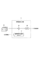
図1を参照して、実施形態に係わる信号機検出装置の全体構成を説明する。信号機検出装置は、車両に搭載され、車両の周囲を所定の時間間隔で繰り返し撮像して、連続する複数の画像(フレーム)を取得する撮像部11と、撮像部11により撮像された画像の中から信号機を検出する信号機検出部12とを備える。
With reference to FIG. 1, the whole structure of the traffic signal detection apparatus concerning embodiment is demonstrated. The traffic light detection device is mounted on a vehicle, repeatedly captures the surroundings of the vehicle at predetermined time intervals, and obtains a plurality of continuous images (frames). Among the images captured by the
撮像部11は、固体撮像素子、例えばCCD又はCMOSを用いたデジタルカメラであって、画像処理が可能なデジタル画像を取得する。デジタルカメラは、画角の広い広角レンズを備える。撮像部11の撮像範囲(画角)には、車両の進行方向から左右方向に車両近傍の路肩までが含まれる。
The
信号機検出部12は、撮像部11により取得された画像(以後、「カメラ画像」という)を受信し、カメラ画像における信号機の位置を検出する。検出された信号機の位置情報は、例えば車両の自動運転を実現するためのコントローラを含む、車両に搭載された他の処理演算装置(車両CPU13)に転送される。信号機検出部12は、例えば、CPU、メモリ25、及び入出力部を備えるマイクロコントローラからなり、予めインストールされたコンピュータプログラムを実行することにより、信号機検出装置が備える複数の情報処理部を構成する。信号機検出部12は、カメラ画像から信号機の位置を検出する一連の情報処理を、連続する複数のカメラ画像(フレーム)毎に繰り返し実行する。信号機検出部12は、車両にかかわる他の制御に用いるECUと兼用してもよい。
The traffic light detection unit 12 receives an image (hereinafter referred to as “camera image”) acquired by the
信号機検出部12により構成される複数の情報処理部には、位相検出部19と、同期画像生成部15と、信号機判断部18とが含まれる。
The plurality of information processing units configured by the traffic signal detection unit 12 include a
メモリ25は、連続する複数のカメラ画像(フレーム)28を同時に記憶する。例えば、信号機に供給される電力の1交流周期の間に撮像される複数のカメラ画像28を同時に記憶する。
The
位相検出部19は、連続する複数のカメラ画像28における輝度変化の周期から、信号機を含む車両周辺における電力系統の位相情報を検出する。信号機の周辺における電力系統の位相情報は、信号灯とその周囲にある他の電灯の間で概ね共通している。すなわち、信号機周辺にある他の電灯に供給される電力の位相は、信号機に供給される電力の位相と概ね一致している。よって、位相検出部19は、カメラ画像28の中の輝度変化の周期から、信号機に供給される電力の位相情報を検出することができる。なお、「電力系統の位相情報」とは、商用電源の位相情報を示す。
The
例えば、図3(a)は、車両からの距離に応じた輝度変化の幅の違いを示すグラフであり、図3(b)は車両近傍にある他の電灯の例として、街灯31a、自動販売機31b、看板31cを示し、車両から遠方にある信号機32、33を示す図である。図3(a)は、図3(b)の街灯31a、及び信号機32、33の輝度変化を示す。車両近傍にある他の電灯(街灯31a、自動販売機31b、看板31c)の輝度変化の幅は、遠方の信号機(32、33)のそれに比べて大きい。また、輝度変化の幅が大きいほど、位相情報の検出精度は向上する。よって、車両近傍にある他の電灯(31a〜31c)の輝度変化の周期から、遠方の信号機(32、33)に供給される電力の位相情報を高精度に検出することができる。
For example, FIG. 3A is a graph showing a difference in the width of the luminance change according to the distance from the vehicle, and FIG. 3B is a
また、位相検出部19は、カメラ画像の各画素の中から、輝度変化の幅が最も大きい画素を選択し、選択した画素を用いて電力系統の位相情報を検出しても構わない。これにより、位相情報の検出精度を最も高めることができる。さらに、輝度変化の幅が比較的大きい画素を積算して、電力系統の位相情報を検出しても構わない。
Further, the
なお、車両の現在位置及び車両周辺の地図情報から、車両近傍にある他の電灯(31a〜31c)の輝度変化を効率よく検出する位相検出部19の変形例を、図4を参照して後述する。
A modified example of the
同期画像生成部15は、位相検出部19により検出された電力系統の位相情報を用いて、カメラ画像の中から、信号機に供給される電力の交流周期と同期して輝度が変化する同期画素を抽出して、抽出された同期画素からなる同期画像を生成する。例えば、同期画像生成部15は、電力系統の位相情報を用いて、信号機に供給される電力の位相に同期した基準信号を生成し、基準信号とカメラ画像の各画素の輝度信号とを乗算する同期検波処理を行う。これにより、信号機に供給される電力の交流周期に同期して輝度が変化する同期画素が抽出される。
The synchronized
信号機に供給される電力は、商用電源の電力を全波整流した交流電力である。商用電源から電力の供給を受けて点灯する信号灯の輝度は、全波整流した交流電力の周期(例えば、100Hz)と同じ周期で変化する。そこで、信号機に供給される電力の交流周期に同期して輝度が変化する同期画素をカメラ画像の中から抽出することにより、商用電源から電力の供給を受けて点灯する信号灯を検出することができる。具体的な処理内容は、図2及び図8を参照して後述する。 The power supplied to the traffic light is AC power obtained by full-wave rectifying the power of the commercial power supply. The luminance of the signal lamp that is turned on when supplied with power from the commercial power supply changes in the same cycle as the cycle of full-wave rectified AC power (for example, 100 Hz). Therefore, by extracting a synchronized pixel whose luminance changes in synchronization with the AC cycle of the power supplied to the traffic light from the camera image, it is possible to detect a signal lamp that is turned on when the power is supplied from the commercial power source. . Specific processing contents will be described later with reference to FIGS.
信号機判断部18は、同期画像生成部15により抽出された同期画素の色相が信号色の色相に類似する場合、同期画素の位置に信号機が存在すると判断する。商用電源から電力の供給を受けて点灯する電灯には、信号機が有する信号灯の他に、図3(b)に示したように街灯31a、自動販売機31b、看板31cなど、路上で点灯している他の電灯が含まれる。同期画像生成部15により抽出された同期画素には、これらの他の電灯も含まれる可能性がある。信号機判断部18が同期画素と信号色との間で色相の類似性を判断することにより、同期画像生成部15の抽出結果から、これらの他の電灯を排除することができる。
When the hue of the synchronization pixel extracted by the synchronization
なお、信号機判断部18は、同期画素の色相が信号色の色相に類似するか否かを判断する色相判断部を用いずに、同期画素の画像上の位置と輝度を用いて、信号機が存在するか否か判断する構成としても良い。車両の周囲の地図情報より画像上の信号機の位置を求め、同期画素の位置と照合することで、上記他の電灯を排除することができる。さらに、車両から信号機までの距離から画像上の輝度を想定し、想定輝度内の同期画素に信号機が存在すると判断することができる。
The traffic
信号機検出部12は、信号機が存在すると信号機判断部18が判断した画素群の位置情報を、車両CPU13に出力する。
The traffic light detection unit 12 outputs position information of the pixel group determined by the traffic
次に、図2及び図8を参照して、同期画像生成部15の詳細を説明する。先ず、図2を参照して、同期画像生成部15の詳細な構成を説明する。同期画像生成部15は、乗算部26と、ローパスフィルタ(LPF)20と、基準信号生成部17とを備える。
Next, details of the synchronized
基準信号生成部17は、電力系統(商用電源)の位相情報を用いて、信号機に供給される電力の位相に同期した基準信号を生成する。乗算部26は、メモリ25から読み出したカメラ画像(フレーム)28の各画素の輝度信号と基準信号とを乗算する。乗算部26は、メモリ25に同時に記憶されている複数のカメラ画像の各々について、上記した乗算処理を実施する。LPF20は、乗算部26による乗算結果のうち、所定の遮断周波数よりも高い周波数成分を低減させて低周波数成分のみを取り出して、同期画素からなる同期画像を出力する。
The reference
図8(a)及び図8(b)を参照して、基準信号の位相の整合性について説明する。図8(a)は、基準信号の位相が、信号機に供給される電力の位相に整合している状態を示す。この状態において、各画素の1)輝度信号と2)基準信号とを乗算することにより、3)乗算後の信号、すなわち同期画素の輝度、及び同期画素の輝度の平均値(相関値G1)は、最も大きな値となる。 With reference to FIG. 8A and FIG. 8B, the phase consistency of the reference signal will be described. FIG. 8A shows a state where the phase of the reference signal matches the phase of the power supplied to the traffic light. In this state, by multiplying 1) the luminance signal and 2) the reference signal of each pixel, 3) the signal after multiplication, that is, the luminance of the synchronous pixel and the average value of the luminance of the synchronous pixel (correlation value G1) , The largest value.
一方、図8(b)は、基準信号の位相が、信号機に供給される電力の位相と反転している状態を示す。この状態において、各画素の1)輝度信号と2)基準信号とを乗算することにより、3)乗算後の信号、すなわち同期画素の輝度、及び同期画素の輝度の平均値(相関値G2)は、最も小さな値となる。 On the other hand, FIG. 8B shows a state in which the phase of the reference signal is inverted from the phase of the power supplied to the traffic light. In this state, by multiplying each pixel by 1) the luminance signal and 2) the reference signal, 3) the signal after multiplication, that is, the luminance of the synchronous pixel and the average value of the luminance of the synchronous pixel (correlation value G2) , The smallest value.
図3に示したように、車両から信号機(32、33)までの距離が遠くなるほど、撮像部11により検出される信号灯の輝度は小さくなり、輝度の変化幅も小さくなる。よって、基準信号の位相を、信号灯の輝度変化の位相、すなわち信号機に供給される電力の位相に近づけることにより、高い相関値(G1)を得ることができ、ひいては遠方の信号機を精度良く検出することができる。
As shown in FIG. 3, as the distance from the vehicle to the traffic light (32, 33) increases, the luminance of the signal lamp detected by the
実施形態では、位相検出部19が、信号機を含む車両周辺における電力系統の位相情報を用いて、信号機に供給される電力の位相を精度良く検出する。これにより、基準信号の位相を、信号灯の輝度変化の位相、すなわち信号機に供給される電力の位相に近づけることができる。
In the embodiment, the
図4を参照して、位相検出部19の変形例を説明する。位相検出部19は、走行路判断部35と、画像領域設定部36と、位相抽出部37とを備える。
A modification of the
走行路判断部35は、GPS機能及び地図データベースを用いて車外或いは車内から取得した自車位置情報及び周辺地図情報に基づいて走行路の状況を判断する。例えば、走行路判断部35は、車両の進行方向の道路形状が図3(b)に示すような直線であるか、或いは右又は左へのカーブであるかを判断する。或いは、図5に示すように車両がトンネルを走行しているか否かを判断する。
The travel
画像領域設定部36は、走行路判断部35により判断された走行路の状況に基づいて、カメラ画像内に画像領域を設定する。例えば、道路形状が直線である場合、図3(b)に示すように、カメラ画像のうち、道路の路肩が撮像される領域(R2、R3)を、画像領域として設定する。これにより、画像領域には、道路の路肩に配置された他の電灯(31a、31b、31c)が含まれる。また、トンネルを走行している場合、図5に示すように、カメラ画像のうち、トンネル内壁に設けられた照明ランプ34が撮像される領域R4を、画像領域として設定する。
The image
位相抽出部37は、画像領域設定部36により設定された画像領域(R2〜R4)の中から、電力系統の位相情報を抽出する。走行路の状況に応じて、輝度変化が大きい電灯があることが推測される画像領域を特定することができるので、車両近傍にある他の電灯(31a〜31c、34)の輝度変化を効率よく検出することができる。
The
次に、図6を参照して、図1に示した信号機検出装置を用いた信号機検出方法を説明する。図6のフローチャートに示す信号機検出装置の動作は、車両のイグニションスイッチがオン状態となり、信号機検出装置が起動すると同時に開始され、信号機検出装置が停止するまで、繰り返し実行される。 Next, a traffic signal detection method using the traffic signal detection apparatus shown in FIG. 1 will be described with reference to FIG. The operation of the traffic light detection device shown in the flowchart of FIG. 6 is repeatedly executed until the ignition switch of the vehicle is turned on, the traffic signal detection device is started, and the traffic signal detection device is stopped.
ステップS01において、撮像部11は、繰り返し車両の周囲を撮像して、連続する複数のカメラ画像を取得する。信号機に供給される電力の1交流周期の間に、複数回の撮像を行う。取得された画像データは、同期画像生成部15に転送され、メモリ25に一時的に記憶される。
In step S01, the
ステップS03〜S07において、位相検出部19は、連続する複数のカメラ画像28の中の輝度変化の周期から、信号機を含む車両周辺における電力系統の位相情報を検出する。その一例として、位相検出部19は、カメラ画像28に含まれる画素の輝度変化の幅(ΔD)が所定の閾値(Th)よりも広くなるか否かに応じて、電力系統の位相情報を検出する。もちろん、図4に示した変形例に係わる位相検出部19が、画像領域設定部36により設定された画像領域(R2〜R4)について、輝度変化の幅(ΔD)が所定の閾値(Th)よりも広くなるか否かを判断してもよい。
In steps S03 to S07, the
先ず、ステップS03において、位相検出部19は、カメラ画像28から任意に画素を選択し、当該画素の輝度変化の幅(ΔD)が所定の閾値(Th)より広いか否かを判断する。所定の閾値(Th)より広い場合(S03でYES)、カメラ画像28から精度良く位相情報を検出することができる。そこで、ステップS05に進み、位相検出部19は、選択した画素の輝度変化の位相を計測する。測定した位相を設定する(ステップS07)。
First, in step S03, the
一方、所定の閾値(Th)より広くない場合(S03でNO)、カメラ画像28から精度良く位相情報を検出することができない。そこで、ステップS09に進み、予め定めた基準位相を設定する。予め定めた基準位相としては、前回或いは2回以上前の制御ループにおけるステップS05で計測された位相を用いることができる。
On the other hand, if it is not wider than the predetermined threshold (Th) (NO in S03), phase information cannot be detected from the
ステップS11に進み、基準信号生成部17は、設定された位相(S07)或いは基準信号(S09)に基づき基準信号を生成する。ステップS13に進み、乗算部26は、基準信号とカメラ画像の各画素の輝度信号とを乗算する同期検波処理を行う。そして、LPF20が低周期の信号をフィルタすることにより、同期画素を抽出する。
In step S11, the reference
ステップS15に進み、信号機判断部18は、同期画像生成部15により抽出された同期画素の色相が信号色の色相に類似するか否かを判断する。信号色の色相に類似する場合、同期画素の位置に信号機が存在すると判断できる。よって、ステップS17に進み、信号機判断部18は、同期画素を信号機としてラベリングする。一方、信号色の色相に類似しない場合(S15でNO)、同期画素の位置に、信号灯でなく、その他の電灯が存在すると判断できる。よって、ステップS19に進み、信号機判断部18は、同期画素を他の電灯としてラベリングする。
In step S15, the traffic
ステップS21に進み、信号機判断部18は、ステップS13で抽出された総ての同期画素について、信号機であるか否かを判断したか否かを判断する。判断が終わっていない場合(S21でNO)、ステップS15に戻り、残りの同期画素について色相の判断処理(S15〜S19)を実施する。判断が終わっている場合(S21でYES)、図6のフローチャートは終了する。
Proceeding to step S21, the traffic
以上説明したように、実施形態によれば以下の作用効果が得られる。 As described above, according to the embodiment, the following operational effects can be obtained.
特許文献1では、カメラ画像の中から信号灯の色相と類似する領域を抽出し、抽出した領域の円形度から信号灯の候補を検出する。円形度から信号灯を判断する場合、領域(画素群53a)に含まれる画素の数は、図7(a)に示す程度の数が必要となる。これに対して、実施形態に係わる信号機検出装置では、上述したように、信号機の輝度変化の幅が小さく、位相周期を検出し難いような遠方に位置する信号機に対して、信号機に供給される電力の交流周期と同期して輝度が変化する同期画素を信号灯の候補として抽出できる。これにより、図7(b)に示すように、同期画素53bの数が、円形度を判断できない程度の数であっても、信号灯であるか否かを判断することができる。すなわち、実施形態に係わる信号機検出装置は、遠方の信号機を精度良く検出することができる。
In Patent Document 1, a region similar to the hue of a signal light is extracted from a camera image, and a candidate for a signal light is detected from the circularity of the extracted region. When judging the signal lamp from the circularity, the number of pixels included in the region (
カメラ画像の中から、信号機に供給される電力の交流周期と同期して輝度が変化する同期画素を抽出することにより、信号灯の大きさ及びその形状を考慮することなく、信号機を検出することができる。よって、円形度を判定できないほど画像サイズが小さくなる遠方の信号機であっても精度良く検出することができる。 By extracting synchronous pixels whose luminance changes in synchronization with the AC cycle of power supplied to the traffic light from the camera image, the traffic light can be detected without considering the size and shape of the traffic light. it can. Therefore, it is possible to accurately detect even a remote traffic signal whose image size is so small that the circularity cannot be determined.
車両周辺における電力系統の位相情報は、信号灯とその周囲にある他の電灯の間で概ね共通している。よって、位相検出部19が信号機に供給される交流電力の位相情報を高精度に検出することにより、同期画像生成部15は、輝度変化が小さい同期画素を高感度に抽出することできる。よって、信号機検出装置は、輝度変化が小さい遠方の信号機であっても精度良く検出することができる。
The phase information of the electric power system around the vehicle is generally common between the signal lamp and other lamps around it. Therefore, when the
輝度変化の幅が大きいほど、より正確な位相情報を検出できる。そこで、位相検出部19は、カメラ画像を構成する画素のうち、輝度変化の幅が最も大きい画素を用いて電力系統の位相情報を検出してもよい。これにより、カメラ画像の中から、信号灯に供給される交流電力の位相情報を高精度に検出することができる。
As the width of the luminance change is larger, more accurate phase information can be detected. Therefore, the
図3(b)に示したように、道路の路肩にある、看板31c、自動販売機31b、街灯31aを含む他の電灯は、遠方の信号機(32、33)に比べて輝度変化の幅が大きい。そこで、位相検出部19は、連続する複数のカメラ画像のうち、道路の路肩が撮像される領域(R2、R3)から、電力系統の位相情報を検出してもよい。これにより、輝度変化の幅が大きい画素を用いて電力系統の位相情報を検出することができる。
As shown in FIG. 3 (b), the other lamps including the
図5に示したように、車両がトンネル内を走行している場合、一般的に、道路の路肩に、看板、自動販売機、街灯を含む電灯は存在しないわかりに、トンネル内壁に設けられた照明ランプ34が存在する。そこで、位相検出部19は、連続する複数のカメラ画像のうち、トンネル内壁に設けられた照明ランプ34が撮像される領域R4から、電力系統の位相情報を検出してもよい。これにより、輝度変化の幅が大きい画素を用いて電力系統の位相情報を検出することができる。
As shown in FIG. 5, when a vehicle is traveling in a tunnel, generally, there is no electric light including a signboard, a vending machine, or a streetlight on the shoulder of the road. There is an
上記のように、本発明の実施形態を記載したが、この開示の一部をなす論述及び図面はこの発明を限定するものであると理解すべきではない。この開示から当業者には様々な代替実施の形態、実施例及び運用技術が明らかとなろう。 Although the embodiments of the present invention have been described as described above, it should not be understood that the descriptions and drawings constituting a part of this disclosure limit the present invention. From this disclosure, various alternative embodiments, examples and operational techniques will be apparent to those skilled in the art.
図3(b)には、車両前方の道路形状が直線である場合の画像領域(R2、R3)を示したが、車両前方の道路形状が右または左へのカーブである場合、路肩が撮像される領域は、カーブ側よりもカーブ方向とは逆側の方が広くなる。カーブの方向に応じて、左右の画像領域(R2、R3)の大きさ及び形状を変化させてもよい。或いは、図5の画像領域R4を、トンネル以外においても適用しても構わない。例えば、車両近傍にある信号機は、図5の画像領域R4において撮像される可能性がある。よって、トンネル以外の走行状況においても、画像領域R4を適用しても構わない。更には、図5の画像領域R4と図3(b)の画像領域(R2、R3)とを同時に設定しても構わない。 FIG. 3B shows an image region (R2, R3) when the road shape ahead of the vehicle is a straight line. When the road shape ahead of the vehicle is a curve to the right or left, the road shoulder is imaged. The area to be applied is wider on the side opposite to the curve direction than on the curve side. Depending on the direction of the curve, the size and shape of the left and right image regions (R2, R3) may be changed. Alternatively, the image region R4 in FIG. 5 may be applied to other than the tunnel. For example, a traffic light in the vicinity of the vehicle may be imaged in the image region R4 in FIG. Therefore, the image region R4 may be applied even in traveling situations other than the tunnel. Furthermore, the image region R4 in FIG. 5 and the image regions (R2, R3) in FIG. 3B may be set simultaneously.
11 撮像部
12 信号機検出部
15 同期画像生成部(同期画素抽出部)
17 基準信号生成部
18 信号機判断部
28 カメラ画像(画像)
33、32 信号機
53b 同期画素
R2〜R4 画像領域DESCRIPTION OF
17 Reference
33, 32
Claims (6)
前記画像の中から信号機を検出する信号機検出部と、を備え、
前記信号機検出部は、
連続する複数の画像の中の前記信号機を除く他の電灯の輝度変化の周期から、前記信号機を含む車両周辺における電力系統の位相情報を検出する位相検出部と、
前記電力系統の位相情報を用いて、前記画像の中から、前記信号機に供給される電力の交流周期と同期して輝度が変化する同期画素を抽出する同期画素抽出部と、
前記同期画素より前記信号機が存在するか否か判断する信号機判断部と、
を有することを特徴とする信号機検出装置。An imaging unit mounted on a vehicle, repeatedly imaging the periphery of the vehicle, and acquiring a plurality of continuous images;
A traffic light detector for detecting a traffic light from the image,
The traffic light detector is
A phase detection unit that detects phase information of a power system around a vehicle including the traffic light from a cycle of a luminance change of other lamps excluding the traffic light in a plurality of continuous images;
Using the phase information of the power system, a synchronized pixel extraction unit that extracts a synchronized pixel whose luminance changes in synchronization with an AC cycle of power supplied to the traffic light from the image,
A traffic light judging unit for judging whether or not the traffic light exists from the synchronous pixel;
A traffic light detection apparatus comprising:
前記位相検出部は、輝度変化の幅が最も大きい画素を用いて前記電力系統の位相情報を検出することを特徴とする信号機検出装置。In the traffic light detection apparatus according to claim 1,
The signal detection device, wherein the phase detection unit detects phase information of the power system using a pixel having the largest width of luminance change.
前記位相検出部は、前記連続する複数の画像のうち、道路の路肩が撮像される領域から、前記電力系統の位相情報を検出することを特徴とする信号機検出装置。
In the traffic light detection apparatus according to claim 1 or 2,
The phase detector, Chi plurality of images sac said consecutive, from the region where the shoulder of the road is taken, traffic signal detecting apparatus characterized by detecting the phase information of the power system.
前記車両がトンネル内を走行している場合、前記位相検出部は、前記連続する複数の画像のうち、トンネル内壁に設けられた照明ランプが撮像される領域から、前記電力系統の位相情報を検出することを特徴とする信号機検出装置。In the traffic light detection apparatus according to claim 1 or 2,
When the vehicle is traveling in a tunnel, the phase detection unit detects phase information of the power system from an area where an illumination lamp provided on the inner wall of the tunnel is imaged among the plurality of continuous images. A traffic light detecting device.
前記信号機判断部は、当該同期画素の色相が信号色の色相に類似するか否かを判断する色相判断部を備え、
前記信号機判断部は、前記同期画素の色相が信号色の色相に類似する場合、前記同期画素の位置に前記信号機が存在すると判断することを特徴とする信号機検出装置。In the traffic light detection apparatus according to any one of claims 1 to 4,
The traffic light determination unit includes a hue determination unit that determines whether the hue of the synchronization pixel is similar to the hue of the signal color,
The traffic light determination unit determines that the traffic light is present at the position of the synchronization pixel when the hue of the synchronization pixel is similar to the hue of the signal color.
連続する複数の画像の中の信号機を除く他の電灯の輝度変化の周期から、前記信号機を含む車両周辺における電力系統の位相情報を検出し、
前記電力系統の位相情報を用いて、前記画像の中から、前記電力系統の交流周期と同期して輝度が変化する同期画素を抽出し、
前記同期画素より前記信号機が存在するか否か判断する
ことを特徴とする信号機検出方法。Repeatedly image the surroundings of the vehicle to obtain multiple consecutive images,
From the period of the luminance change of the other lights excluding the traffic lights in a plurality of continuous images, detect phase information of the power system around the vehicle including the traffic lights,
Using the phase information of the power system, from the image, extract a synchronous pixel whose luminance changes in synchronization with the AC cycle of the power system,
It is judged whether the said traffic signal exists from the said synchronous pixel. The traffic signal detection method characterized by the above-mentioned.
Applications Claiming Priority (1)
| Application Number | Priority Date | Filing Date | Title |
|---|---|---|---|
| PCT/JP2014/056195 WO2015136601A1 (en) | 2014-03-10 | 2014-03-10 | Traffic light detection device and traffic light detection method |
Publications (2)
| Publication Number | Publication Date |
|---|---|
| JPWO2015136601A1 JPWO2015136601A1 (en) | 2017-04-06 |
| JP6233500B2 true JP6233500B2 (en) | 2017-11-22 |
Family
ID=54071081
Family Applications (1)
| Application Number | Title | Priority Date | Filing Date |
|---|---|---|---|
| JP2016507146A Active JP6233500B2 (en) | 2014-03-10 | 2014-03-10 | Signal detection device and signal detection method |
Country Status (8)
| Country | Link |
|---|---|
| US (1) | US9679208B2 (en) |
| EP (1) | EP3118831B1 (en) |
| JP (1) | JP6233500B2 (en) |
| CN (1) | CN106068531B (en) |
| BR (1) | BR112016020884B1 (en) |
| MX (1) | MX350751B (en) |
| RU (1) | RU2628639C1 (en) |
| WO (1) | WO2015136601A1 (en) |
Families Citing this family (12)
| Publication number | Priority date | Publication date | Assignee | Title |
|---|---|---|---|---|
| EP3118831B1 (en) * | 2014-03-10 | 2019-05-22 | Nissan Motor Co., Ltd | Traffic light detection device and traffic light detection method |
| EP3323237B1 (en) * | 2015-08-26 | 2025-05-14 | Zhejiang Dahua Technology Co., Ltd | Methods and systems for traffic monitoring |
| CN105118295B (en) * | 2015-09-25 | 2019-01-15 | 浙江宇视科技有限公司 | Detect the method and device of traffic lights illuminating state |
| US9990548B2 (en) * | 2016-03-09 | 2018-06-05 | Uber Technologies, Inc. | Traffic signal analysis system |
| JP7090251B2 (en) * | 2016-08-08 | 2022-06-24 | バイエリシエ・モトーレンウエルケ・アクチエンゲゼルシヤフト | A method of detecting an LED light source in a series of image frames, a method of detecting a traffic signal light having at least one LED light source, and a vehicle. |
| US10380438B2 (en) * | 2017-03-06 | 2019-08-13 | Honda Motor Co., Ltd. | System and method for vehicle control based on red color and green color detection |
| US10614326B2 (en) * | 2017-03-06 | 2020-04-07 | Honda Motor Co., Ltd. | System and method for vehicle control based on object and color detection |
| US10525903B2 (en) * | 2017-06-30 | 2020-01-07 | Aptiv Technologies Limited | Moving traffic-light detection system for an automated vehicle |
| US11334753B2 (en) | 2018-04-30 | 2022-05-17 | Uatc, Llc | Traffic signal state classification for autonomous vehicles |
| CN110021176B (en) * | 2018-12-21 | 2021-06-15 | 文远知行有限公司 | Traffic light decision-making method, device, computer equipment and storage medium |
| US11983855B2 (en) * | 2019-05-31 | 2024-05-14 | Nippon Telegraph And Telephone Corporation | Image processing apparatus, image processing method, and program |
| EP4213112B1 (en) | 2022-01-13 | 2025-12-03 | Bayerische Motoren Werke Aktiengesellschaft | Method and device for detecting a color of a traffic light in an environment of a vehicle |
Family Cites Families (24)
| Publication number | Priority date | Publication date | Assignee | Title |
|---|---|---|---|---|
| JP2005301518A (en) | 2004-04-08 | 2005-10-27 | Toyota Motor Corp | Traffic signal detection apparatus and traffic signal detection method |
| JP4979933B2 (en) * | 2005-12-16 | 2012-07-18 | 株式会社オートネットワーク技術研究所 | In-vehicle camera and drive recorder |
| CN101042802A (en) * | 2006-03-23 | 2007-09-26 | 安捷伦科技有限公司 | Traffic information sensor and method and system for traffic information detecting |
| JP2007286943A (en) * | 2006-04-18 | 2007-11-01 | Fujifilm Corp | Signal light detection device |
| JP2008134916A (en) * | 2006-11-29 | 2008-06-12 | Denso Corp | In-vehicle vehicle front recognition device |
| JP4265662B2 (en) * | 2007-02-06 | 2009-05-20 | 株式会社デンソー | Vehicle communication device |
| US9019377B2 (en) * | 2007-02-13 | 2015-04-28 | Fujitsu Ten Limited | Drive recorder, drive recorder system, vehicle-mounted video recording apparatus, and vehicle-mounted video recording method |
| JP4915281B2 (en) | 2007-05-24 | 2012-04-11 | アイシン・エィ・ダブリュ株式会社 | Signal detection device, signal detection method and program |
| JP2008293227A (en) * | 2007-05-24 | 2008-12-04 | Hitachi Ltd | Progress management device |
| JP5537491B2 (en) * | 2011-05-12 | 2014-07-02 | 富士重工業株式会社 | Environment recognition device |
| JP5386539B2 (en) * | 2011-05-12 | 2014-01-15 | 富士重工業株式会社 | Environment recognition device |
| US9690997B2 (en) * | 2011-06-06 | 2017-06-27 | Denso Corporation | Recognition object detecting apparatus |
| JP5803402B2 (en) * | 2011-08-08 | 2015-11-04 | 株式会社ソシオネクスト | Image processing apparatus, imaging apparatus, imaging system, and data processing method |
| RU2011142883A (en) * | 2011-10-12 | 2013-04-20 | Виктор Иванович Дикарев | DEVICE FOR INCREASING ROAD SAFETY |
| JP5480925B2 (en) * | 2012-03-05 | 2014-04-23 | 本田技研工業株式会社 | Vehicle periphery monitoring device |
| JP5908125B2 (en) * | 2013-01-25 | 2016-04-26 | 三菱電機株式会社 | Movement support apparatus and movement support method |
| JP6325000B2 (en) * | 2013-12-25 | 2018-05-16 | 日立オートモティブシステムズ株式会社 | In-vehicle image recognition device |
| JP5852637B2 (en) * | 2013-12-27 | 2016-02-03 | 富士重工業株式会社 | Arrow signal recognition device |
| WO2015116950A1 (en) * | 2014-01-30 | 2015-08-06 | Anna Clarke | Systems and methods for lane end recognition |
| EP3118831B1 (en) * | 2014-03-10 | 2019-05-22 | Nissan Motor Co., Ltd | Traffic light detection device and traffic light detection method |
| CN106062851B (en) * | 2014-03-10 | 2018-05-29 | 日产自动车株式会社 | Signal machine detecting device and semaphore detection method |
| JP6370134B2 (en) * | 2014-07-02 | 2018-08-08 | キヤノン株式会社 | Imaging device, control method thereof, and control program |
| JP2016037283A (en) * | 2014-08-08 | 2016-03-22 | 株式会社リコー | Information processing apparatus, information processing method, and program |
| US20170024622A1 (en) * | 2015-07-24 | 2017-01-26 | Honda Motor Co., Ltd. | Surrounding environment recognition device |
-
2014
- 2014-03-10 EP EP14885213.0A patent/EP3118831B1/en active Active
- 2014-03-10 MX MX2016011330A patent/MX350751B/en active IP Right Grant
- 2014-03-10 RU RU2016139365A patent/RU2628639C1/en active
- 2014-03-10 JP JP2016507146A patent/JP6233500B2/en active Active
- 2014-03-10 WO PCT/JP2014/056195 patent/WO2015136601A1/en not_active Ceased
- 2014-03-10 US US15/124,534 patent/US9679208B2/en active Active
- 2014-03-10 CN CN201480076936.0A patent/CN106068531B/en active Active
- 2014-03-10 BR BR112016020884-6A patent/BR112016020884B1/en not_active IP Right Cessation
Also Published As
| Publication number | Publication date |
|---|---|
| CN106068531A (en) | 2016-11-02 |
| CN106068531B (en) | 2017-12-22 |
| US20170017850A1 (en) | 2017-01-19 |
| RU2628639C1 (en) | 2017-08-21 |
| BR112016020884A2 (en) | 2017-08-15 |
| BR112016020884B1 (en) | 2022-01-11 |
| WO2015136601A1 (en) | 2015-09-17 |
| JPWO2015136601A1 (en) | 2017-04-06 |
| EP3118831A4 (en) | 2017-03-08 |
| EP3118831B1 (en) | 2019-05-22 |
| US9679208B2 (en) | 2017-06-13 |
| MX2016011330A (en) | 2016-11-08 |
| EP3118831A1 (en) | 2017-01-18 |
| MX350751B (en) | 2017-09-18 |
Similar Documents
| Publication | Publication Date | Title |
|---|---|---|
| JP6233500B2 (en) | Signal detection device and signal detection method | |
| JP6222343B2 (en) | Signal detection device and signal detection method | |
| KR101972690B1 (en) | Signal device detection device and signal device detection method | |
| JP6477876B2 (en) | Signal detection device and signal detection method | |
| JP6233501B2 (en) | Signal detection device and signal detection method | |
| JP6432601B2 (en) | Signal detection device and signal detection method | |
| JP6455596B2 (en) | Lamp detection device and lamp detection method |
Legal Events
| Date | Code | Title | Description |
|---|---|---|---|
| A521 | Request for written amendment filed |
Free format text: JAPANESE INTERMEDIATE CODE: A523 Effective date: 20161117 |
|
| A621 | Written request for application examination |
Free format text: JAPANESE INTERMEDIATE CODE: A621 Effective date: 20161117 |
|
| TRDD | Decision of grant or rejection written | ||
| A01 | Written decision to grant a patent or to grant a registration (utility model) |
Free format text: JAPANESE INTERMEDIATE CODE: A01 Effective date: 20170926 |
|
| A61 | First payment of annual fees (during grant procedure) |
Free format text: JAPANESE INTERMEDIATE CODE: A61 Effective date: 20171009 |
|
| R151 | Written notification of patent or utility model registration |
Ref document number: 6233500 Country of ref document: JP Free format text: JAPANESE INTERMEDIATE CODE: R151 |