JP6046880B2 - Refurbishment method to electric shutter device - Google Patents

Refurbishment method to electric shutter device Download PDF

Info

Publication number
JP6046880B2
JP6046880B2 JP2011123334A JP2011123334A JP6046880B2 JP 6046880 B2 JP6046880 B2 JP 6046880B2 JP 2011123334 A JP2011123334 A JP 2011123334A JP 2011123334 A JP2011123334 A JP 2011123334A JP 6046880 B2 JP6046880 B2 JP 6046880B2
Authority
JP
Japan
Prior art keywords
electric
support bracket
shaft
winding shaft
shutter device
Prior art date
Legal status (The legal status is an assumption and is not a legal conclusion. Google has not performed a legal analysis and makes no representation as to the accuracy of the status listed.)
Active
Application number
JP2011123334A
Other languages
Japanese (ja)
Other versions
JP2012251331A (en
Inventor
昇 矢澤
昇 矢澤
Current Assignee (The listed assignees may be inaccurate. Google has not performed a legal analysis and makes no representation or warranty as to the accuracy of the list.)
Bunka Shutter Co Ltd
Original Assignee
Bunka Shutter Co Ltd
Priority date (The priority date is an assumption and is not a legal conclusion. Google has not performed a legal analysis and makes no representation as to the accuracy of the date listed.)
Filing date
Publication date
Application filed by Bunka Shutter Co Ltd filed Critical Bunka Shutter Co Ltd
Priority to JP2011123334A priority Critical patent/JP6046880B2/en
Publication of JP2012251331A publication Critical patent/JP2012251331A/en
Application granted granted Critical
Publication of JP6046880B2 publication Critical patent/JP6046880B2/en
Active legal-status Critical Current
Anticipated expiration legal-status Critical

Links

Images

Landscapes

  • Operating, Guiding And Securing Of Roll- Type Closing Members (AREA)

Description

本発明は、シャッターカーテンを巻き取り、繰り出すための手動式巻取軸が、電動モータの駆動力で回転する電動式巻取軸に改修された電動式シャッター装置に係り、例えば、窓用シャッター装置や出入口用シャッター装置を含む各種のシャッター装置に利用できるものである。   The present invention relates to an electric shutter device in which a manual winding shaft for winding and unwinding a shutter curtain is modified to an electric winding shaft that is rotated by a driving force of an electric motor, for example, a window shutter device And can be used for various shutter devices including a shutter device for entrance and exit.

窓サッシの外側に配設される窓用シャッター装置では、巻取軸がシャッターカーテンの巻き取り、繰り出しのための回転を行うことにより、シャッターカーテンは上下に開閉移動する。巻取軸が、シャッターカーテンを手や操作棒等により人為的に上下動させることによる手動によって回転する手動式巻取軸となっているシャッター装置については、シャッター装置の取り扱い容易化や高品質化等のため、この手動式巻取軸を、電動モータの駆動力で回転する電動式巻取軸に改修することが求められる場合がある。このため、手動式巻取軸を電動式巻取軸に改修するための技術が従来より知られている(例えば、特許文献1参照)。   In the window shutter device disposed outside the window sash, the winding shaft rotates up and down to move up and down as the winding shaft rotates for winding and unwinding the shutter curtain. For shutter devices that have a winding shaft that is manually rotated by manually moving the shutter curtain up and down manually with a hand or operating rod, the shutter device is easier to handle and has higher quality. For this reason, it may be required to renovate the manual winding shaft to an electric winding shaft that rotates with the driving force of the electric motor. For this reason, a technique for repairing a manual winding shaft to an electric winding shaft has been conventionally known (for example, see Patent Document 1).

特開2004−257063号公報JP 2004-257063 A

ところで、手動式巻取軸を電動式巻取軸に交換するためには、手動式巻取軸を支持していた支持用ブラケットに電動式巻取軸を連結するという作業が必要になる。   By the way, in order to replace the manual winding shaft with the electric winding shaft, it is necessary to connect the electric winding shaft to the support bracket that has supported the manual winding shaft.

しかし、支持用ブラケットは全体的に平面形状となっているため、この支持用ブラケットに対して電動式巻取軸を連結する作業を容易にするための工夫が求められている。   However, since the support bracket has a planar shape as a whole, a device for facilitating the operation of connecting the electric winding shaft to the support bracket is required.

本発明の目的は、手動式巻取軸を電動式巻取軸に交換するために、支持用ブラケットと電動式巻取軸の連結作業が容易になる改修された電動式シャッター装置を提供するところにある。   SUMMARY OF THE INVENTION An object of the present invention is to provide a modified electric shutter device that makes it easy to connect a support bracket and an electric take-up shaft in order to replace a manual take-up shaft with an electric take-up shaft. It is in.

本発明に係る改修された電動式シャッター装置は、シャッターカーテンを巻き取り、繰り出すための手動式巻取軸が、内部に電動モータが収納されていてこの電動モータの駆動力により回転する電動式巻取軸に改修されているとともに、前記手動式巻取軸を支持していた支持用ブラケットが残されて改修されている改修された電動式シャッター装置において、前記電動式巻取軸と前記支持用ブラケットは、これらの電動式巻取軸と支持用ブラケットとの間に介入されている中間構成体により連結され、この中間構成体は、前記電動式巻取軸の側の第1中間物と、前記支持用ブラケットの側の第2中間物とを含んで構成され、これらの第1中間物と第2中間物とが接続されることにより、前記電動式巻取軸と前記支持用ブラケットとが連結されていることを特徴とするものである。   In the modified electric shutter device according to the present invention, the manual winding shaft for winding and unwinding the shutter curtain has an electric motor housed therein and is rotated by the driving force of the electric motor. In the modified electric shutter device that has been modified to the take-up shaft and has been repaired with the support bracket that supported the manual take-up shaft remaining, the electric take-up shaft and the support shaft The bracket is connected by an intermediate structure interposed between the electric winding shaft and the support bracket, and the intermediate structure includes a first intermediate on the electric winding shaft side, A second intermediate on the support bracket side, and by connecting the first intermediate and the second intermediate, the electric winding shaft and the support bracket Concatenated It is characterized in that there.

本発明では、前記電動式巻取軸と前記支持用ブラケットは、これらの電動式巻取軸と支持用ブラケットとの間に介入されている中間構成体により連結されるが、この中間構成体は、前記電動式巻取軸の側の第1中間物と、前記支持用ブラケットの側の第2中間物とを含んで構成されている。そして、これらの第1中間物と第2中間物とが接続されることにより、前記電動式巻取軸と前記支持用ブラケットとが連結されているものである。   In the present invention, the electric winding shaft and the support bracket are connected by an intermediate structure interposed between the electric winding shaft and the support bracket. The first intermediate on the electric take-up shaft side and the second intermediate on the support bracket side are configured. Then, the electric intermediate shaft and the support bracket are coupled by connecting the first intermediate and the second intermediate.

ここで、前記中間構成体を1個の部材とした場合には、この1個の中間構成体のうちの一方の側を、前述したように全体的に平面形状となっている前記支持用ブラケットに取り付ける必要があり、前記電動式巻取軸と前記支持用ブラケットを連結する作業は容易ではない。   Here, when the intermediate structure is a single member, one side of the one intermediate structure has the planar shape as a whole as described above. It is necessary to attach to the electric winding shaft, and the operation of connecting the electric winding shaft and the support bracket is not easy.

これに対して、本発明では、前記電動式巻取軸と前記支持用ブラケットとを連結する作業は、前記第1中間物を前記電動式巻取軸の側へ配置する(取り付ける)とともに、前記第2中間物を前記支持用ブラケットの側へ配置した(取り付けた)後、これらの第1中間物と第2中間物同士を接続すればよい。   On the other hand, in the present invention, the operation of connecting the electric take-up shaft and the support bracket arranges (attaches) the first intermediate to the electric take-up shaft side, and After the second intermediate is disposed (attached) to the support bracket side, the first intermediate and the second intermediate may be connected to each other.

このため、本発明によると、手動式巻取軸を電動式巻取軸に交換するために、支持用ブラケットと電動式巻取軸の連結作業が容易になる。   Therefore, according to the present invention, since the manual winding shaft is replaced with the electric winding shaft, the connection work between the support bracket and the electric winding shaft is facilitated.

本発明において、前記電動式巻取軸の軸方向の両端部のうちのいずれか一方の端部と、この一方の端部を支持するための前記支持用ブラケットを、前記電動式巻取軸の前記一方の端部とこの一方の端部を支持するための前記支持用ブラケットとの間に介入されている中間構成体により連結してもよく、前記電動式巻取軸の軸方向の両端部のそれぞれと、それぞれの端部を支持するための前記支持用ブラケットを、それぞれの前記電動式巻取軸の前記端部とこの端部を支持するための前記支持用ブラケットとの間に介入されている中間構成体により連結してもよい。   In the present invention, either one of the axial ends of the electric winding shaft and the support bracket for supporting the one end of the electric winding shaft are provided on the electric winding shaft. The both ends in the axial direction of the electric winding shaft may be connected by an intermediate structure interposed between the one end and the support bracket for supporting the one end. And the support brackets for supporting the respective end portions are interposed between the end portions of the respective electric winding shafts and the support brackets for supporting the end portions. The intermediate structure may be connected.

すなわち、前記電動式巻取軸の軸方向の両端部のうちのいずれか一方の端部のみが中間構成体を介して前記支持用ブラケットに連結されるようにしてもよく、前記電動式巻取軸の軸方向の両端部が中間構成体を介して前記支持用ブラケットに連結されるようにしてもよい。   That is, only one of the end portions in the axial direction of the electric winding shaft may be connected to the support bracket via an intermediate structure, You may make it the both ends of the axial direction of an axis | shaft connect with the said bracket for support through an intermediate structure.

本発明において、前記支持用ブラケットの側の前記第2中間物は、前記支持用ブラケットに直接取り付けられているものでもよく、前記支持用ブラケットに設けられている部材(例えば、前記手動式巻取軸の端部を受けていた後述する軸受け部)を介して間接的に取り付けられているものでもよい。   In the present invention, the second intermediate on the side of the support bracket may be directly attached to the support bracket, and a member provided on the support bracket (for example, the manual winding) It may be attached indirectly via a bearing portion (to be described later) that has received the end portion of the shaft.

本発明において、前記支持用ブラケットには、前記手動式巻取軸の端部を受けていた(支持していた)軸受け部が残されていてもよく、この残された軸受け部を取り外して交換した新たな軸受け部が設けられていてもよい。   In the present invention, the supporting bracket may be left with a bearing portion that has received (supported) the end portion of the manual winding shaft, and the remaining bearing portion may be removed and replaced. A new bearing portion may be provided.

この場合において、前記中間構成体は、前記軸受け部によって邪魔されないで前記電動式巻取軸と前記支持用ブラケットとの間に介入されていることが好ましい。   In this case, it is preferable that the intermediate structure is intervened between the electric winding shaft and the support bracket without being obstructed by the bearing portion.

これによると、前記支持用ブラケットと前記電動式巻取軸の連結作業が、前記軸受け部によって邪魔されずにスムーズに行われるようになる。   According to this, the connection work of the support bracket and the electric take-up shaft is smoothly performed without being obstructed by the bearing portion.

本発明において、上述したように、前記支持用ブラケットに前記軸受け部が設けられている場合には、前記第2中間物は、前記軸受け部を越えて前記電動式巻取軸の側へ突出した長さ寸法を有していることが好ましい。   In the present invention, as described above, when the bearing portion is provided on the support bracket, the second intermediate projects beyond the bearing portion toward the electric winding shaft. It preferably has a length dimension.

これによると、前記第1中間物を前記第2中間物に接続させるとき、前記軸受け部が邪魔にならない。すなわち、これによると、前記第1中間物を前記第2中間物に接続させるとき、前記第1中間物が前記軸受け部と干渉することを防止することができ、前記支持用ブラケットと前記電動式巻取軸の連結作業が容易となる。   According to this, when the first intermediate is connected to the second intermediate, the bearing portion does not get in the way. That is, according to this, when the first intermediate is connected to the second intermediate, the first intermediate can be prevented from interfering with the bearing portion, and the support bracket and the electric type can be prevented. The winding shaft can be easily connected.

本発明において、上述したように、前記支持用ブラケットに前記軸受け部が設けられている場合には、前記軸受け部の形状、構造は任意なものでよく、その一例として、軸受け部本体と、この軸受け部本体における前記支持用ブラケットの側の端部から前記電動式巻取軸の外径方向に突出し、前記支持用ブラケットに結合されているフランジ部とを有し、前記第2中間物には、前記軸受け部本体を内部に挿入するための開口部と、前記フランジ部を前記支持用ブラケットとの間に収容するためのフランジ部収容部と、前記軸受け部本体を越えて前記電動式巻取軸の側へ突出した突出部と、が設けられているものを挙げることができる。   In the present invention, as described above, when the bearing portion is provided on the support bracket, the shape and structure of the bearing portion may be arbitrary. As an example, the bearing portion main body, A flange portion projecting in an outer diameter direction of the electric take-up shaft from an end portion of the bearing portion main body on the support bracket side and coupled to the support bracket; and the second intermediate An opening for inserting the bearing body into the interior; a flange housing part for housing the flange between the support bracket; and the electric winding over the bearing body. The thing provided with the protrusion part which protruded to the shaft side can be mentioned.

本発明において、前記第1中間物は、1個の部材で構成されたものでもよく、あるいは、複数個の部材で構成されたものでもよい。また、前記第2中間物も、1個の部材で構成されたものでもよく、あるいは、複数個の部材で構成されたものでもよい。   In the present invention, the first intermediate may be composed of a single member or may be composed of a plurality of members. Also, the second intermediate may be composed of one member, or may be composed of a plurality of members.

本発明において、前記軸受け部が上述した形状、構造を有している場合には、前記第2中間物の形状、構造も任意なものでよく、その一例として、前記開口部が形成された第1部材と、この第1部材よりも小さい面積を有するとともに、前記フランジ部の厚さ寸法に対応する厚さ寸法を有している第2部材と、前記第1部材及び前記第2部材から前記電動式巻取軸の側へ突出した第3部材と、を含んで構成され、前記第1部材における前記支持用ブラケットの側の面に前記第2部材が結合されることにより、前記第2中間物に前記フランジ部収容部が形成されているものを挙げることができる。   In the present invention, when the bearing portion has the shape and structure described above, the shape and structure of the second intermediate may be arbitrary, and as an example, the second portion in which the opening is formed. A first member, a second member having a smaller area than the first member and having a thickness corresponding to a thickness of the flange, and the first member and the second member A third member projecting toward the electric take-up shaft, and the second member is coupled to a surface of the first member on the support bracket side, whereby the second intermediate The thing in which the said flange part accommodating part is formed in the thing can be mentioned.

これによると、前記開口部と前記フランジ部収容部とを有している前記第2中間物を、複数の部材の組み合わせにより容易に製造することができる。   According to this, the said 2nd intermediate which has the said opening part and the said flange part accommodating part can be manufactured easily by the combination of a some member.

また、これによると、前記第2中間物に、前記軸受け部を構成している前記軸受け部本体と、この軸受け部本体の前記支持用ブラケットの側の端部から前記電動式巻取軸の外径方向に突出する前記フランジ部との両方を挿入できる大きな開口部を形成することが不要になるため、この第2中間物の充分に大きな強度を確保することができる。   Further, according to this, the second intermediate product includes the bearing portion main body constituting the bearing portion, and an end portion of the bearing portion main body on the side of the support bracket that is outside the electric winding shaft. Since it is not necessary to form a large opening into which both the flange projecting in the radial direction can be inserted, a sufficiently large strength of the second intermediate can be ensured.

本発明において、前記第2中間物が上述した形状、構造を有している場合には、前記第1中間物の形状、構造も任意なものでよく、その一例として、前記電動式巻取軸の側の第1部材と、この第1部材から前記支持用ブラケットの側へ突出した第2部材とを含んで構成され、前記第2中間物の前記第3部材と、前記第1中間物の前記第2部材とが接続されることにより、前記第2中間物と前記第1中間物とが連結されるものを挙げることができる。   In the present invention, when the second intermediate has the shape and structure described above, the shape and structure of the first intermediate may be arbitrary, and as an example, the electric winding shaft And a second member projecting from the first member toward the support bracket, the third member of the second intermediate, and the first intermediate of the first intermediate As the second member, the second intermediate and the first intermediate can be connected to each other.

本発明において、前記第1中間物及び前記第2中間物が上述した形状、構造を有している場合には、これらの第1中間物と第2中間物を配置する位置は任意であるが、前記第2中間物の前記第3部材と、前記第1中間物の前記第2部材を、改修作業者から見て手前側に配置することが好ましい。   In the present invention, when the first intermediate and the second intermediate have the shape and structure described above, the positions where the first intermediate and the second intermediate are arranged are arbitrary. Preferably, the third member of the second intermediate and the second member of the first intermediate are disposed on the near side as viewed from the repair worker.

これによると、前記第2中間物の前記第3部材と、前記第1中間物の前記第2部材を、改修作業者から見て奥側に配置した場合と比較して、前記第2中間物の前記第3部材と、前記第1中間物の前記第2部材とを接続する作業が容易となる。   According to this, compared with the case where the 3rd member of the 2nd intermediate and the 2nd member of the 1st intermediate are arranged in the back side seeing from a repair worker, the 2nd intermediate The operation of connecting the third member and the second member of the first intermediate is facilitated.

本発明において、前記第1中間物と前記第2中間物を上述した位置に配置した場合には、前記第2中間物の前記第3部材と前記第1中間物の前記第2部材とを接続させる方法、手段は任意なものでよいが、前記第2中間物の前記第3部材と前記第1中間物の前記第2部材同士が接離(接続、分離)自在となる方法、手段であることが好ましい。   In the present invention, when the first intermediate and the second intermediate are arranged at the positions described above, the third member of the second intermediate and the second member of the first intermediate are connected. Any method and means may be used, but the third member of the second intermediate and the second member of the first intermediate can be contacted and separated (connected and separated). It is preferable.

前記第2中間物の前記第3部材と前記第1中間物の前記第2部材とを接続させる方法、手段の一例として、前記第2中間物の前記第3部材と前記第1中間物の前記第2部材を、前記改修作業者から見て手前側からドライバー等の工具等で回転させることができるビス等の接続具で互いに接続するようにしたものを挙げることができる。   As an example of a method and means for connecting the third member of the second intermediate and the second member of the first intermediate, the third member of the second intermediate and the first intermediate The second member can be connected to each other with a connecting tool such as a screw that can be rotated by a tool such as a screwdriver from the front side as viewed from the repair worker.

これによると、前記改修作業者は、この改修作業者から見て手前側から、ドライバー等の前記工具等で回転させることができるビス等の前記接続具で、前記第2中間物の前記第3部材と前記第1中間物の前記第2部材とを容易に接続する(連結する)ことができる。また、ビス等の前記接続具で互いに接続されているこれらの第2中間物の第3部材と第1中間物の第2部材とを、ドライバー等の前記工具等で容易に分離する(切り離す)ことができる。   According to this, the repair worker can connect the third intermediate of the second intermediate with the connection tool such as a screw that can be rotated by the tool such as a screwdriver from the front side as viewed from the repair worker. The member and the second member of the first intermediate can be easily connected (coupled). Further, the third member of the second intermediate and the second member of the first intermediate that are connected to each other by the connection tool such as a screw are easily separated (separated) by the tool such as a screwdriver. be able to.

なお、本発明において、前述したように、前記軸受け部の前記フランジ部に、前記軸受け部本体の下部から下方へ突出する1個の第1突出部と、前記軸受け部本体の両側部から水平方向又は略水平方向へ突出する2個の第2突出部とがある場合には、前記第2中間物の前記第1部材における前記支持用ブラケットの側の面に結合される前記第2部材を上下2個とし、これらの第2部材のうち、少なくとも下側の第2部材に、第1突出部を収納するための凹部を形成するとともに、上下2個の第2部材の間に、第2突出部を収納するための間隔を設けるようにしてもよい。   In the present invention, as described above, the flange portion of the bearing portion has one first projecting portion projecting downward from the lower portion of the bearing portion main body, and the horizontal direction from both side portions of the bearing portion main body. Alternatively, when there are two second projecting portions projecting in a substantially horizontal direction, the second member coupled to the surface of the first member of the second intermediate on the side of the support bracket is moved up and down. Of these second members, at least a lower second member is formed with a recess for accommodating the first protrusion, and a second protrusion is formed between the upper and lower second members. You may make it provide the space | interval for accommodating a part.

これによると、前記第2中間物の前記第1部材における前記支持用ブラケットの側の面に上下2個の前記第2部材を結合することにより、前記軸受け部の前記第1突出部と前記第2突出部を収容するための前記フランジ部収容部を容易に設けることができる。   According to this, by connecting the upper and lower two second members to the surface on the support bracket side of the first member of the second intermediate, the first projecting portion of the bearing portion and the first member 2 The flange portion accommodating portion for accommodating the protruding portion can be easily provided.

また、上下2個の前記第2部材のうち、上側の第2部材にも、第1突出部が収納可能となった凹部を形成し、これらの第2部材により、前記第2中間物を上下逆転して使用可能とするようにしてもよい。   Further, of the two upper and lower second members, the upper second member is also formed with a recess in which the first protruding portion can be accommodated, and the second intermediate member is moved up and down by these second members. You may make it usable reversely.

これによると、前記第2中間物の前記上下2個の第2部材には上下の区別がなくなるため、これらの第2部材を前記支持用ブラケットに結合する際に、上下を気にすることなくこの結合作業を容易に行えるようになる。   According to this, since the upper and lower two second members of the second intermediate are not distinguished from each other, there is no need to worry about the upper and lower sides when connecting these second members to the support bracket. This joining operation can be easily performed.

以上の本発明において、前記電動式巻取軸の内部に収納されてこの電動式巻取軸を回転させるための前記電動モータは、ブレーキと組み合わせられて開閉機の一部を構成する構成要素となっているものでもよく、ブレーキ等と組み合わせられず、前記電動モータ単独となっているものでもよい。   In the present invention described above, the electric motor housed in the electric take-up shaft for rotating the electric take-up shaft is combined with a brake to constitute a part of the switch. It may be the one that is not combined with the brake or the like, and may be the electric motor alone.

また、以上の本発明において、前記電動式巻取軸で巻き取られ、繰り出される前記シャッターカーテンが複数種類のシャッターカーテン構成部材の複合により形成されていてもよく、これらの複数種類のシャッターカーテン構成部材は、スラットでもよく、シートでもよく、ネットでもよく、リンクで連結されたパイプ、パネル等でもよい。   In the present invention described above, the shutter curtain wound and fed out by the electric winding shaft may be formed by combining a plurality of types of shutter curtain constituent members, and the plurality of types of shutter curtain configurations. The member may be a slat, a sheet, a net, or a pipe or panel connected by a link.

また、本発明は、シャッターカーテンが巻取軸で巻き取られ、繰り出される各種のシャッター装置に適用することができ、その一例のシャッター装置は窓用シャッター装置であり、また、本発明は、出入口をシャッターカーテンで開閉する出入口用シャッター装置等にも適用することができる。   In addition, the present invention can be applied to various shutter devices in which a shutter curtain is wound around a winding shaft and fed out. One example of the shutter device is a window shutter device. It can also be applied to an entrance / exit shutter device that opens and closes with a shutter curtain.

本発明によると、手動式巻取軸を電動式巻取軸に交換するために、支持用ブラケットと電動式巻取軸の連結作業が容易になるという効果を得られる。   According to the present invention, since the manual take-up shaft is replaced with the electric take-up shaft, the effect of facilitating the connection work between the support bracket and the electric take-up shaft can be obtained.

図1は、本発明の一実施形態が適用される窓用シャッター装置の全体を示す正面図である。FIG. 1 is a front view showing an entire window shutter device to which an embodiment of the present invention is applied. 図2は、図1で示されている手動式巻取軸の端部が支持用ブラケットで支持されている構造を示す斜視図である。FIG. 2 is a perspective view showing a structure in which an end portion of the manual winding shaft shown in FIG. 1 is supported by a support bracket. 図3は、図2の支持構造を示す分解斜視図である。FIG. 3 is an exploded perspective view showing the support structure of FIG. 図4は、手動式巻取軸から改修される電動式巻取軸の構造を示す正断面図である。FIG. 4 is a front sectional view showing the structure of the electric take-up shaft modified from the manual take-up shaft. 図5は、電動式巻取軸に改修された後の窓用電動式シャッター装置の一部を示す正面図である。FIG. 5 is a front view showing a part of the windowed electric shutter device after being modified to the electric winding shaft. 図6は、図5のS6−S6線断面図である。6 is a cross-sectional view taken along line S6-S6 of FIG. 図7は、電動式巻取軸における図4の右側の端部の支持用ブラケットによる支持構造を示す斜視図である。FIG. 7 is a perspective view showing a support structure by a support bracket at the right end of FIG. 4 in the electric winding shaft. 図8は、図7の支持構造を示す分解斜視図である。FIG. 8 is an exploded perspective view showing the support structure of FIG. 図9は、電動式巻取軸の内部に収納されていて、電動モータが構成要素となっている開閉機が、中間構成体を介して図4の左側の支持用ブラケットで支持されている構造を示す正面図である。FIG. 9 shows a structure in which an opening / closing machine housed in an electric take-up shaft and having an electric motor as a component is supported by a support bracket on the left side of FIG. 4 via an intermediate component. FIG. 図9の支持構造を示す平面図である。It is a top view which shows the support structure of FIG. 図11は、図9のS11−S11線断面図である。11 is a cross-sectional view taken along line S11-S11 in FIG. 図12は、図9のS12−S12線断面図である。12 is a cross-sectional view taken along line S12-S12 of FIG. 図13は、図9で示されている中間構成体のうち、開閉機(電動モータ)の側となっている第1中間物を構成するそれぞれの部材を示す分解斜視図である。FIG. 13 is an exploded perspective view showing each member constituting the first intermediate on the switch (electric motor) side in the intermediate structure shown in FIG. 9. 図14は、図9で示されている中間構成体のうち、支持用ブラケットの側となっている第2中間物を構成するそれぞれの部材を示す分解斜視図である。FIG. 14 is an exploded perspective view showing the respective members constituting the second intermediate on the support bracket side in the intermediate structure shown in FIG. 9. 図15は、第1中間物の正面図である。FIG. 15 is a front view of the first intermediate. 図16は、第1中間物の側面図である。FIG. 16 is a side view of the first intermediate. 図17は、第2中間物の正面図である。FIG. 17 is a front view of the second intermediate. 図18は、第2中間物の側面図である。FIG. 18 is a side view of the second intermediate. 図19は、図4の左側の支持用ブラケットに設けられている軸受け部を示す側面図である。FIG. 19 is a side view showing a bearing portion provided on the left support bracket of FIG. 4. 図20は、図19の軸受け部に適用される部材であって、図14で示されている第2中間物を構成するものとなっている部材を示す側面図である。FIG. 20 is a side view showing a member that is applied to the bearing portion of FIG. 19 and that constitutes the second intermediate shown in FIG. 図21は、図19の軸受け部とは形状等が異なる別の軸受け部を示す側面図である。FIG. 21 is a side view showing another bearing portion that is different in shape and the like from the bearing portion of FIG. 図22は、図21の軸受け部に適用される部材であって、図20の部材に対応している部材を示す側面図である。22 is a side view showing a member applied to the bearing portion of FIG. 21 and corresponding to the member of FIG. 図23は、図7及び図8に示されている紐状部材を支持用ブラケットに通すためにこの支持用ブラケットに設けられる案内部材の実施形態を示す正断面図である。FIG. 23 is a front sectional view showing an embodiment of a guide member provided on the support bracket in order to pass the string-like member shown in FIGS. 7 and 8 through the support bracket. 図24は、図23の案内部材とは異なる別実施形態に係る案内部材を示す正断面図である。24 is a front sectional view showing a guide member according to another embodiment different from the guide member of FIG.

以下に本発明を実施するための形態を図面に基づいて説明する。図1には、本発明の一実施形態が適用される窓用シャッター装置の全体正面図が示されている。図1に示されているこの窓用シャッター装置は、電動式シャッター装置に改修される前の手動式シャッター装置である。   EMBODIMENT OF THE INVENTION Below, the form for implementing this invention is demonstrated based on drawing. FIG. 1 shows an overall front view of a window shutter device to which an embodiment of the present invention is applied. The window shutter device shown in FIG. 1 is a manual shutter device before being modified to an electric shutter device.

図1の手動式の窓用シャッター装置は、障子1が配設された窓サッシよりも外側の建物外壁2の部分に設置され、この窓用シャッター装置の手動用シャッターカーテン3は、左右一対のガイドレール4に案内されて上下に開閉移動することにより、窓サッシの外側の窓用開口部を開閉する。この窓用開口部の上部にはシャッターケース5が配設され、このシャッターケース5の内部に水平に収納されている手動式巻取軸6にシャッターカーテン3の上端が連結されているとともに、この手動式巻取軸6は、左右一対の支持用ブラケット7,8で回転自在に支持されている。   The manual window shutter device shown in FIG. 1 is installed on a part of the building outer wall 2 outside the window sash in which the shoji 1 is disposed. The manual shutter curtain 3 of the window shutter device includes a pair of left and right windows. The window opening on the outside of the window sash is opened and closed by being guided by the guide rail 4 and moving up and down. A shutter case 5 is disposed above the window opening, and an upper end of the shutter curtain 3 is connected to a manual take-up shaft 6 accommodated horizontally in the shutter case 5. The manual winding shaft 6 is rotatably supported by a pair of left and right support brackets 7 and 8.

なお、シャッターケース5は、本体5Aと、この本体5Aの左右両端を塞いでいる左右一対の蓋部材5B,5Cとからなる。   The shutter case 5 includes a main body 5A and a pair of left and right lid members 5B and 5C that close both left and right ends of the main body 5A.

シャッターカーテン3の下端の座板3A等を手等による手動で押し上げると、シャッターカーテン3は巻取軸6に巻き取られて上方へ開き移動し、座板3A等を押し下げると、シャッターカーテン3は巻取軸6から繰り出されて下方へ閉じ移動する。また、巻取軸6の内部には、シャッターカーテン3が巻取軸6から繰り出されるときに戻しばね力が蓄圧されるねじりコイルばねによる戻しばねが収納されており、このため、シャッターカーテン3が巻取軸6に巻き取られて上方へ開き移動することは、この戻しばねの戻しばね力によって補助されて行われる。   When the seat plate 3A at the lower end of the shutter curtain 3 is manually pushed up by hand or the like, the shutter curtain 3 is wound around the take-up shaft 6 and moved upward. When the seat plate 3A is pushed down, the shutter curtain 3 is It is drawn out from the take-up shaft 6 and moved downwardly. The take-up shaft 6 houses a return spring by a torsion coil spring that accumulates a return spring force when the shutter curtain 3 is drawn out from the take-up shaft 6. Winding up and moving upward on the winding shaft 6 is performed with the aid of the return spring force of the return spring.

左右一対の支持用ブラケット7,8による巻取軸6の支持は、巻取軸6の軸方向両端の端部となっている軸部6A,6Bが、これらのブラケット7,8に設けられている軸受け部9,10で支持されることにより行われている。図2には、支持用ブラケット7,8のうち、一方のブラケット8の軸受け部10による巻取軸6の軸部6Bの支持構造が示しており、他方のブラケット7及び軸受け部9と、この軸受け部9による巻取軸6の軸部6Aの支持構造は、図2で示されているものと左右対称の同じものになっている。   The winding shaft 6 is supported by the pair of left and right support brackets 7 and 8, and shaft portions 6 A and 6 B that are ends at both ends in the axial direction of the winding shaft 6 are provided on these brackets 7 and 8. This is performed by being supported by the bearing portions 9 and 10. FIG. 2 shows a support structure of the shaft portion 6B of the winding shaft 6 by the bearing portion 10 of one bracket 8 of the support brackets 7 and 8, and the other bracket 7 and the bearing portion 9 The support structure of the shaft portion 6A of the winding shaft 6 by the bearing portion 9 is the same as that shown in FIG.

次に、手動式巻取軸6の構造及び図2の支持構造を説明する。前述したように手動式巻取軸6の内部には、シャッターカーテン3が巻取軸6から繰り出されるときに戻しばね力が蓄圧される戻しばねが収納されているため、図2で示されている軸部6Bは、巻取軸6の内部に端部を残して挿入されている非回転軸のこの端部により形成され、この非回転軸との間に軸受け部材が介設されている巻取軸6は、この非回転軸を中心に回転自在となっている。また、この非回転軸又は上記軸部6Aを形成している別の非回転軸には、巻取軸6の内部に収納されている戻しばねの一端が連結され、戻しばねの他端は巻取軸6に連結されている。このため、上述のように、シャッターカーテン3が巻取軸6から繰り出されるときには、巻取軸6の回転により戻しばねに戻しばね力が蓄圧され、シャッターカーテン3が巻取軸6に巻き取られるときの巻取軸6の回転は、戻しばね力によって補助される。   Next, the structure of the manual winding shaft 6 and the support structure of FIG. 2 will be described. As described above, the manual type take-up shaft 6 contains a return spring in which the return spring force is accumulated when the shutter curtain 3 is drawn out from the take-up shaft 6. The shaft portion 6B is formed by this end portion of the non-rotating shaft that is inserted into the winding shaft 6 while leaving the end portion, and a bearing member is interposed between the non-rotating shaft and the winding portion 6B. The take-up shaft 6 is rotatable around this non-rotating shaft. Further, one end of a return spring housed in the take-up shaft 6 is connected to this non-rotation shaft or another non-rotation shaft forming the shaft portion 6A, and the other end of the return spring is wound around the other end of the return spring. The shaft 6 is connected. Therefore, as described above, when the shutter curtain 3 is unwound from the take-up shaft 6, the return spring force is accumulated on the return spring by the rotation of the take-up shaft 6, and the shutter curtain 3 is taken up by the take-up shaft 6. The rotation of the winding shaft 6 is assisted by the return spring force.

図2に示されているように、板金製のブラケット8は、ブラケット本体8Aと、このブラケット本体8Aの補強のためにも設けられている後端折曲部8Bと、下端折曲部8Cとを有するものとなっており、後端折曲部8Bが図1で示した建物外壁2にアンカー部材等の結合具で結合されることにより、ブラケット8は建物外壁2に固定されている。そして、ブラケット本体8Aには、巻取軸6の軸部6Bを受けて支持するための上記軸受け部10が設けられている。   As shown in FIG. 2, the bracket 8 made of sheet metal includes a bracket main body 8A, a rear end bent portion 8B provided for reinforcement of the bracket main body 8A, and a lower end bent portion 8C. The bracket 8 is fixed to the building outer wall 2 by joining the rear bent portion 8B to the building outer wall 2 shown in FIG. The bracket main body 8A is provided with the bearing portion 10 for receiving and supporting the shaft portion 6B of the winding shaft 6.

この軸受け部10は、板金の折り曲げ品となっている1個の軸受け部材で形成されており、また、軸受け部10は、軸受け部本体16と、この軸受け部本体16におけるブラケット本体8Aの側から巻取軸6の外径方向に突出しているフランジ部17とからなる。軸受け部本体16は、底部16Aと、この底部16Aの両端から立ち上がった立上部16B,16Cとを有するため、上向きに開口したコ字形状となっている。また、フランジ部17は、軸受け部本体16の下部から、言い換えると底部16Aから下方へ突出する第1突出部17Aと、軸受け部本体16の両側部から、言い換えると立上部16B,16Cから水平方向又は略水平方向に突出する2個の第2突出部17B,17Cとからなり、これらの第1及び第2突出部17A〜17Cがブラケット本体8Aに溶接又はリベット等の結合具で結合されることにより、上記軸受け部材によって形成されている軸受け部10が支持用ブラケット8に設けられていることになる。   The bearing portion 10 is formed by a single bearing member that is a bent product of a sheet metal. The bearing portion 10 is formed from the bearing portion body 16 and the bracket body 8A side of the bearing portion body 16. The flange portion 17 protrudes in the outer diameter direction of the winding shaft 6. The bearing portion main body 16 has a bottom portion 16A and rising portions 16B and 16C rising from both ends of the bottom portion 16A, and thus has a U-shape opening upward. Further, the flange portion 17 extends horizontally from the lower portion of the bearing portion main body 16, in other words, from the first protruding portion 17 </ b> A that protrudes downward from the bottom portion 16 </ b> A, and from both sides of the bearing portion main body 16, in other words, from the upright portions 16 </ b> B and 16 </ Or it consists of two 2nd protrusion parts 17B and 17C which protrude in a substantially horizontal direction, and these 1st and 2nd protrusion parts 17A-17C are couple | bonded with brackets 8A with coupling tools, such as welding or a rivet. Thus, the bearing portion 10 formed by the bearing member is provided on the support bracket 8.

図3に示されているように、軸受け部本体16の立上部16B,16Cと巻取軸6の軸部6Bには、孔11〜13が形成され、軸部6Bを軸受け部本体16に挿入した後に、これらの孔11〜13にボルト14を挿入し、立上部16Cの孔13から突出したボルト14の軸端にナット15を螺合することにより、手動式巻取軸6の端部を形成している軸部6Bは、非回転状態となって軸受け部10の軸受け部本体16で支持されることになる。   As shown in FIG. 3, holes 11 to 13 are formed in the upright portions 16 </ b> B and 16 </ b> C of the bearing body 16 and the shaft section 6 </ b> B of the winding shaft 6, and the shaft section 6 </ b> B is inserted into the bearing section body 16. After that, the bolts 14 are inserted into the holes 11 to 13, and the nuts 15 are screwed into the shaft ends of the bolts 14 protruding from the holes 13 of the upright portion 16C. The formed shaft portion 6B is in a non-rotating state and is supported by the bearing portion main body 16 of the bearing portion 10.

図4は、窓用手動式シャッター装置を窓用電動式シャッター装置に改修するために、手動式巻取軸6から交換される電動式巻取軸20を示している。この電動式巻取軸20における支持用ブラケット8の側の端部の内部には、電動モータとブレーキの組み合わせからなる開閉機21が収納されている。図4では、電気配線は省略されている。開閉機21のブレーキは、後述するように、巻取軸20が電動モータの回転駆動力により回転してシャッターカーテン3が全開位置や全閉位置に達したことが巻取軸20の回転数検出センサ等で検出されて、この検出信号が図示しない制御装置に入力したときや、電動モータの回転や停止を操作するための操作装置からの停止信号がこの制御装置に入力したときに、電動モータの出力部材の回転駆動を停止させて巻取軸20を回転停止状態とするためのものである。   FIG. 4 shows an electric take-up shaft 20 that is replaced from the manual take-up shaft 6 in order to upgrade the manual shutter device for windows to an electric shutter device for windows. An opening / closing machine 21 made of a combination of an electric motor and a brake is housed inside the end of the electric winding shaft 20 on the support bracket 8 side. In FIG. 4, electrical wiring is omitted. As will be described later, the brake of the opening / closing machine 21 detects the number of rotations of the winding shaft 20 when the winding shaft 20 is rotated by the rotational driving force of the electric motor and the shutter curtain 3 reaches the fully open position or the fully closed position. When the detection signal is input to a control device (not shown) detected by a sensor or the like, or when a stop signal from an operation device for operating rotation or stop of the electric motor is input to the control device, the electric motor This is to stop the rotation drive of the output member and put the winding shaft 20 in the rotation stopped state.

開閉機21には、電動モータの出力部材の回転駆動により回転するリング状の駆動部材22が設けられ、この駆動部材22の円周方向に複数形成されている溝22Aに、巻取軸20の内面に設けられている突起20Aが挿入されているため、駆動部材22と巻取軸20は、巻取軸20の回転方向に連結されている。このため、電動モータの出力部材の回転駆動により駆動部材22が回転すると、巻取軸20は回転することになる。また、開閉機21の外周には、巻取軸20と一体となって回転するリング状の従動部材23が嵌合され、電動モータの回転駆動力による巻取軸20の回転は、この従動部材23が、巻取軸20と開閉機21との間の回転軸受け部材となって行われる。   The opening / closing machine 21 is provided with a ring-shaped drive member 22 that is rotated by the rotational drive of the output member of the electric motor, and a plurality of grooves 22 </ b> A formed in the circumferential direction of the drive member 22 has the winding shaft 20. Since the protrusion 20 </ b> A provided on the inner surface is inserted, the drive member 22 and the winding shaft 20 are connected in the rotational direction of the winding shaft 20. For this reason, when the drive member 22 rotates by the rotational drive of the output member of the electric motor, the winding shaft 20 rotates. Further, a ring-shaped driven member 23 that rotates integrally with the winding shaft 20 is fitted to the outer periphery of the opening / closing machine 21, and the rotation of the winding shaft 20 by the rotational driving force of the electric motor is the driven member. 23 is performed as a rotary bearing member between the winding shaft 20 and the switch 21.

一方、電動式巻取軸20における支持用ブラケット7の側の端部の内部には、戻しばねユニット24が挿入されている。この戻しばねユニット24は、非回転の中心軸25と、この中心軸25に軸受け部材26で回転自在に配置された2個のホイール部材27と、これらのホイール部材27の間に配設されたねじりコイルばねによる2個の戻しばね28とを含んで構成されている。それぞれのホイール部材27は巻取軸20にリベット等で結合され、また、それぞれの戻しばね28の一端は連結具29Aで中心軸25に連結されているとともに、他端は連結具29Bでそれぞれのホイール部材27に連結されている。   On the other hand, a return spring unit 24 is inserted into the end of the electric winding shaft 20 on the support bracket 7 side. The return spring unit 24 is disposed between the non-rotating central shaft 25, two wheel members 27 rotatably disposed on the central shaft 25 by bearing members 26, and the wheel members 27. And two return springs 28 by a torsion coil spring. Each wheel member 27 is coupled to the take-up shaft 20 by rivets or the like, and one end of each return spring 28 is coupled to the central shaft 25 by a coupling tool 29A, and the other end is coupled to the winding shaft 29 by a coupling tool 29B. The wheel member 27 is connected.

このため、電動式巻取軸20に後述する電動用シャッターカーテンの上端が連結された後に、この電動用シャッターカーテンを巻き取っている電動式巻取軸20が、電動モータの回転駆動力により非回転の中心軸25を中心に回転して電動用シャッターカーテンが繰り出されたときには、戻しばね28に戻しばね力が蓄圧され、この戻しばね力は、電動式巻取軸20が電動モータの回転駆動力により逆回転して電動用シャッターカーテンを巻き取るときに、補助力として利用される。   For this reason, after the upper end of an electric shutter curtain, which will be described later, is connected to the electric take-up shaft 20, the electric take-up shaft 20 winding the electric shutter curtain is not driven by the rotational driving force of the electric motor. When the electric shutter curtain is drawn out by rotating around the central shaft 25 of rotation, the return spring force is accumulated in the return spring 28, and this return spring force is driven by the electric winding shaft 20 to rotate the electric motor. This is used as an auxiliary force when the electric shutter curtain is wound up in reverse by force.

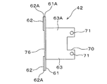
本実施形態では、図4に示されているように、中心軸25の軸端部25Aは巻取軸20から突出しており、このため、この軸端部25Aは、電動式巻取軸20における支持用ブラケット7の側の端部を形成しており、また、この軸端部25Aは、手動式巻取軸6のときにも使用されていたこの支持用ブラケット7の軸受け部9で支持されている。そして、これらの軸端部25Aと軸受け部9は、図7及び図8で示されているように、図3及び図4で説明したと同様な構造により、ボルト14及びナット15により連結されている。   In the present embodiment, as shown in FIG. 4, the shaft end portion 25 </ b> A of the central shaft 25 protrudes from the winding shaft 20, and therefore, this shaft end portion 25 </ b> A is in the electric winding shaft 20. An end portion on the side of the support bracket 7 is formed, and the shaft end portion 25A is supported by the bearing portion 9 of the support bracket 7 which is also used for the manual winding shaft 6. ing. The shaft end portion 25A and the bearing portion 9 are connected by a bolt 14 and a nut 15 with the same structure as described in FIGS. 3 and 4 as shown in FIGS. Yes.

このため、本実施形態では、電動式巻取軸20における支持用ブラケット7の側の端部を形成している中心軸25の軸端部25Aを支持するためにも、窓用手動式シャッター装置における既存の支持用ブラケット7と、この支持用ブラケット7のブラケット本体7Aに設けられている既存の軸受け部9が用いられている。   For this reason, in this embodiment, in order to support the shaft end portion 25A of the central shaft 25 forming the end portion on the support bracket 7 side of the electric winding shaft 20, the manual shutter device for windows is used. The existing support bracket 7 and the existing bearing 9 provided on the bracket body 7A of the support bracket 7 are used.

図9には、図2及び図3で説明した支持用ブラケット8に、電動式巻取軸20における支持用ブラケット8の側の端部を連結支持させるための構造が示されており、図9は、この構造の正面図であり、図10は、この構造の平面図である。電動式巻取軸20におけるこの支持用ブラケット8の側の端部は、中間構成体30により支持用ブラケット8のブラケット本体8Aに連結支持されている。一層具体的には、電動式巻取軸20の内部に収納固定されている開閉機21における支持用ブラケット8の側の端部21Aは、この巻取軸20から露出しており、電動モータが構成要素となっている開閉機21のこの端部21Aが、中間構成体30により支持用ブラケット8のブラケット本体8Aに連結支持されることにより、電動式巻取軸20における支持用ブラケット8の側の端部と、支持用ブラケット8のブラケット本体8Aとが、開閉機21及び中間構成体30を介して連結支持されている。   FIG. 9 shows a structure for connecting and supporting the end of the electric take-up shaft 20 on the side of the support bracket 8 to the support bracket 8 described in FIG. 2 and FIG. FIG. 10 is a front view of this structure, and FIG. 10 is a plan view of this structure. The end of the electric take-up shaft 20 on the side of the support bracket 8 is connected and supported to the bracket body 8A of the support bracket 8 by an intermediate structure 30. More specifically, an end portion 21A on the support bracket 8 side of the switch 21 housed and fixed inside the electric winding shaft 20 is exposed from the winding shaft 20, and the electric motor is The end 21A of the opening / closing device 21 that is a constituent element is connected and supported to the bracket body 8A of the support bracket 8 by the intermediate structure 30, whereby the support bracket 8 side of the electric winding shaft 20 is supported. And the bracket main body 8 </ b> A of the support bracket 8 are connected and supported via the switch 21 and the intermediate structure 30.

したがって、前述した手動式巻取軸6から電動式巻取軸20に改修された後でも、既存の支持用ブラケット8がそのまま用いられており、また、この支持用ブラケット8に設けられている図2及び図3で示した軸受け部10はそのまま残されている。そして、開閉機21と支持用ブラケット8のブラケット本体8Aとを連結するための中間構成体30は、後述の説明から分かるように、軸受け部10に邪魔されずに開閉機21と支持用ブラケット8のブラケット本体8Aとの間に介入されている。   Therefore, the existing support bracket 8 is used as it is even after the manual take-up shaft 6 is modified to the electric take-up shaft 20, and the support bracket 8 is also provided. The bearing 10 shown in FIGS. 2 and 3 is left as it is. The intermediate structure 30 for connecting the opening / closing machine 21 and the bracket main body 8A of the supporting bracket 8 is not obstructed by the bearing portion 10 and can be understood from the description below. The bracket body 8A is interposed.

図5には、手動式巻取軸6から電動式巻取軸20に改修された後の窓用電動式シャッター装置の正面図が示されており、本実施形態では、手動式巻取軸6から電動式巻取軸20に改修されるときに、図1で示した手動用シャッターカーテン3は図5で示した電動用シャッターカーテン31に改修されている。電動式巻取軸20に上端が連結されているこの電動用シャッターカーテン31の左右両端部は、図1で示した左右一対のガイドレール4に上下スライド自在に挿入され、このシャッターカーテン31は、電動式巻取軸20による巻き取り、繰り出しにより、これらのガイドレール4で案内されて上下方向に開閉移動する。そして、シャッターカーテン31の全体は、座板等の付属的部材を除き、多数のスラット32を上下に連設することにより形成されている。   FIG. 5 shows a front view of the windowed electric shutter device after the manual winding shaft 6 has been modified to the electric winding shaft 20, and in this embodiment, the manual winding shaft 6 is shown. 1 to the electric winding shaft 20, the manual shutter curtain 3 shown in FIG. 1 is retrofitted to the electric shutter curtain 31 shown in FIG. The left and right ends of the electric shutter curtain 31 whose upper end is connected to the electric take-up shaft 20 are slidably inserted into the pair of left and right guide rails 4 shown in FIG. By winding and unwinding by the electric winding shaft 20, the guide rail 4 guides and opens and closes up and down. The entirety of the shutter curtain 31 is formed by connecting a large number of slats 32 in the vertical direction, excluding ancillary members such as a seat plate.

図6は、図5のS6−S6線断面図であり、この図6に示されているように、それぞれのスラット32の上下両端にはカール部33が形成され、上側のスラット32Aの下端カール部33Aと、下側のスラット32Bの上端カール部33Bとが係合することにより、これらのスラット32A,32Bは回動自在に連結されている。そして、それぞれのカール部33は左右方向へ同一断面形状が連続するものとなっているため、左右一対のガイドレール4から外れた箇所では、すなわち、図5で示されているシャッターケース5の内部の箇所では、それぞれのスラット32は左右方向にスライドする可能性のある状態になっている。   6 is a cross-sectional view taken along line S6-S6 of FIG. 5. As shown in FIG. 6, curl portions 33 are formed at the upper and lower ends of each slat 32, and the lower end curl of the upper slat 32A is formed. The portion 33A and the upper end curl portion 33B of the lower slat 32B engage with each other so that the slats 32A and 32B are rotatably connected. Since each curled portion 33 has the same cross-sectional shape in the left-right direction, the curled portion 33 is located away from the pair of left and right guide rails 4, that is, inside the shutter case 5 shown in FIG. In this place, each slat 32 is in a state of being slidable in the left-right direction.

なお、図1で示した手動用シャッターカーテン3の少なくとも一部が、複数のスラットの連設で形成されているときには、本実施形態に係る上述の中間構成体30は、手動式巻取軸6から電動式巻取軸20に改修された後にこの手動用シャッターカーテン3を電動用シャッターカーテンとして用いる場合にも、適用することができる。   In addition, when at least a part of the manual shutter curtain 3 shown in FIG. 1 is formed by connecting a plurality of slats, the intermediate structure 30 according to the present embodiment includes the manual winding shaft 6. The present invention can also be applied to the case where the manual shutter curtain 3 is used as the electric shutter curtain after being modified to the electric take-up shaft 20.

すなわち、少なくとも一部がスラットの連設で形成されている既存の手動用シャッターカーテン3を電動用シャッターカーテンとして用いる場合にも、本実施形態に係る中間構成体30は適用することができる。   That is, the intermediate structure 30 according to the present embodiment can also be applied to the case where the existing manual shutter curtain 3 at least partially formed by connecting slats is used as an electric shutter curtain.

図4に示されているように、開閉機21からはワイヤー等による紐状部材35が導出されている。この紐状部材35は、電動モータと共に開閉機21の構成要素となっている前述のブレーキを、電動式巻取軸20の回転が停止しているときに、オン、オフ切り替え操作するための切替部材である。すなわち、ブレーキがオンとなっているために電動式巻取軸20の回転が停止しているシャッターカーテンの全開時や全閉時等において、例えば、停電になった場合に、紐状部材35が1回引っ張り操作されると、ブレーキはオフとなるため、巻取軸が手動式巻取軸6から電動式巻取軸20に改修されていても、この電動式巻取軸20は自由回転可能状態となり、このため、電動用シャッターカーテン31を手動により開閉移動させることができる。また、紐状部材35がもう1回引っ張り操作されると、ブレーキはオンとなるため、開閉機21は上述の引っ張り操作前の状態に戻り、電動式巻取軸20は自由回転不能状態となって、電動用シャッターカーテン31を手動により開閉移動させることはできなくなる。   As shown in FIG. 4, a string-like member 35 made of a wire or the like is led out from the opening / closing machine 21. This string-like member 35 is a switch for switching on and off the above-mentioned brake, which is a component of the switch 21 together with the electric motor, when the rotation of the electric winding shaft 20 is stopped. It is a member. That is, when the shutter is fully open or fully closed, for example, when a power failure occurs, the string-like member 35 is When the pulling operation is performed once, the brake is turned off. Therefore, even if the winding shaft is modified from the manual winding shaft 6 to the electric winding shaft 20, the electric winding shaft 20 can freely rotate. Therefore, the electric shutter curtain 31 can be manually opened and closed. When the string-like member 35 is pulled once more, the brake is turned on, so the switch 21 returns to the state before the pulling operation, and the electric winding shaft 20 is in a state where it cannot rotate freely. Thus, the electric shutter curtain 31 cannot be manually opened and closed.

図4から分かるように、紐状部材35は開閉機21から延びているとともに、この紐状部材35は、中空部材となっている前述の中心軸25の一方の端部からこの中心軸25の内部に挿通されている。また、図7及び図8から分かるように、電動式巻取軸20の延長軸線と一致又は略一致している支持用ブラケット7のブラケット本体7Aの箇所には孔36が形成されており、この支持用ブラケット7は、上述した中間構成体30が設けられている支持用ブラケット8とは電動式巻取軸20の軸方向の反対側に配置されている支持用ブラケットであり、この支持用ブラケット7に孔36が形成されている箇所は、支持用ブラケット7のブラケット本体7Aに設けられている前述の軸受け部9に邪魔されない箇所となっている。中心軸25の内部に挿通されてさらにこの中心軸25の他方の端部から突出した紐状部材35は、孔36に通されているため、紐状部材35は、軸受け部9と干渉することなく、言い換えると、軸受け部9に邪魔されることなく配線されている。   As can be seen from FIG. 4, the string-like member 35 extends from the opening / closing machine 21, and the string-like member 35 extends from one end of the above-described central shaft 25 which is a hollow member. It is inserted inside. Further, as can be seen from FIGS. 7 and 8, a hole 36 is formed in the bracket main body 7 </ b> A of the support bracket 7 that coincides with or substantially coincides with the extension axis of the electric winding shaft 20. The support bracket 7 is a support bracket disposed on the opposite side of the electric winding shaft 20 in the axial direction from the support bracket 8 provided with the intermediate structure 30 described above, and this support bracket. 7, the hole 36 is formed so as not to be disturbed by the above-described bearing portion 9 provided in the bracket body 7 </ b> A of the support bracket 7. Since the string-like member 35 that is inserted into the center shaft 25 and protrudes from the other end of the center axis 25 is passed through the hole 36, the string-like member 35 interferes with the bearing portion 9. In other words, it is wired without being disturbed by the bearing 9.

これ以後の紐状部材35の配線状態は、図5に示されており、紐状部材35は、図1で説明したシャッターケース5の一方の蓋部材5Bに取り付けられたキャップ部材37の内部に挿入され、さらに、紐状部材35はキャップ部材37及び蓋部材5Bから導出され、紐状部材35の終端部は、左右一対のガイドレール4のうちの一方に配置された引張操作部材38に連結されている。このため、この引張操作部材38を引っ張り操作することにより、紐状部材35を介して開閉機21のブレーキがオン、オフ切り替えることになる。   The wiring state of the string-like member 35 thereafter is shown in FIG. 5, and the string-like member 35 is placed inside the cap member 37 attached to one lid member 5B of the shutter case 5 described in FIG. Further, the string-like member 35 is led out from the cap member 37 and the lid member 5B, and the terminal portion of the string-like member 35 is connected to a tension operation member 38 disposed on one of the pair of left and right guide rails 4. Has been. For this reason, when the pulling operation member 38 is pulled, the brake of the switch 21 is switched on and off via the string-like member 35.

図5には、開閉機21の電動モータに給電するための電気回路も示されている。この電気回路の電源線39は、シャッターケース5の他方の蓋部材5Cに取り付けられたキャップ部材40からこの蓋部材5Cに内部に挿入され、さらに、この電源線39は、前述した支持用ブラケット8のブラケット本体8Aに形成されている孔に挿通されているとともに、このブラケット本体8Aに連結されている中間構成体30の内部にも挿通され、これにより、電源線39は、開閉機21の電動モータや、この電動モータを制御するために開閉機21に設けられている制御装置まで達している。   FIG. 5 also shows an electric circuit for supplying power to the electric motor of the switch 21. The power line 39 of the electric circuit is inserted into the lid member 5C from a cap member 40 attached to the other lid member 5C of the shutter case 5, and the power line 39 is further connected to the support bracket 8 described above. Is inserted into a hole formed in the bracket main body 8A, and also inserted into the intermediate structure 30 connected to the bracket main body 8A. The motor and the control device provided in the switch 21 to control the electric motor are reached.

また、電源線39を通すために支持用ブラケット8のブラケット本体8Aに形成されている上記孔は、電動式巻取軸20の延長軸線と一致又は略一致しているこのブラケット本体8Aの箇所に形成されており、この箇所は、支持用ブラケット8に設けられている軸受け部10に邪魔されない箇所となっているため、電源線39は、この軸受け部10と干渉することなく、すなわち、軸受け部10に邪魔されることなく配線されている。   Further, the hole formed in the bracket main body 8A of the support bracket 8 for passing the power supply line 39 is located at a position of the bracket main body 8A that is coincident with or substantially coincides with the extension axis of the electric winding shaft 20. Since this portion is formed and is not obstructed by the bearing portion 10 provided in the support bracket 8, the power line 39 does not interfere with the bearing portion 10, that is, the bearing portion. It is wired without being disturbed by 10.

また、図5には、開閉機21と支持用ブラケット8との間が電源線39と平行に配線されているアース線49も示され、このアース線49は、上記支持用ブラケット8が中継部材として利用されて下方へ延びている。   FIG. 5 also shows a ground wire 49 in which the switch 21 and the support bracket 8 are wired in parallel with the power supply line 39. The ground wire 49 is connected to the support bracket 8 by a relay member. It is used as and extends downward.

さらに、図面では示されていないが、手動式巻取軸6から電動式巻取軸20に改修するときには、電動用シャッターカーテン31を遠隔操作により開き移動、閉じ移動、移動停止させることができるようにするために、電動式窓用シャッター装置には、電動式巻取軸20を正回転、逆回転、回転停止させるための「開」、「閉」、「停」のそれぞれのボタンが設けられている操作装置が追加される。   Further, although not shown in the drawings, when the manual winding shaft 6 is refurbished to the electric winding shaft 20, the electric shutter curtain 31 can be opened, closed, moved and stopped by remote control. In order to achieve this, the electric window shutter device is provided with “open”, “closed”, and “stop” buttons for rotating the electric winding shaft 20 forward, reverse, and rotation. Operating device is added.

この操作装置は、開閉機21の電動モータを駆動制御するための上述した制御装置と無線方式によって接続されるものでもよく、あるいは、この制御装置と信号線を用いる有線方式で接続されるものでもよい。操作装置が制御装置と信号線による有線方式で接続されるものである場合には、この信号線は、図5で示したシャッターケース5の蓋部材5Cに形成された孔及び支持用ブラケット8のブラケット本体8Aに形成された孔に通されて、制御装置が配置されている電動式巻取軸20の側へ配線される。なお、この信号線を、図5で示されている蓋部材5Cに取り付けられたキャップ部材40に形成した孔に通して、蓋部材5Cに形成された孔や、支持用ブラケット8のブラケット本体8Aに形成された孔に通してもよい。   This operation device may be connected to the above-described control device for driving and controlling the electric motor of the switch 21 by a wireless method, or may be connected to this control device by a wired method using a signal line. Good. When the operating device is connected to the control device by a wired system using a signal line, the signal line is formed by the hole formed in the cover member 5C of the shutter case 5 shown in FIG. It is passed through a hole formed in the bracket body 8A and wired to the electric winding shaft 20 side where the control device is arranged. The signal line is passed through a hole formed in the cap member 40 attached to the lid member 5C shown in FIG. 5, and the hole formed in the lid member 5C or the bracket body 8A of the support bracket 8 is provided. You may pass through the hole formed.

また、この信号線を、図5で示したシャッターケース5の蓋部材5Bに形成された孔及び支持用ブラケット7のブラケット本体7Aに形成された孔に通して、制御装置が配置されている電動式巻取軸20の側へ配線してもよく、さらに、この信号線を、蓋部材5Bに取り付けられたキャップ部材37に形成した孔に通して、蓋部材5Cに形成された孔や、支持用ブラケット8のブラケット本体8Aに形成された孔に通してもよい。   The signal line is passed through the hole formed in the lid member 5B of the shutter case 5 and the hole formed in the bracket body 7A of the support bracket 7 shown in FIG. May be wired to the side of the take-up shaft 20, and further, this signal line is passed through a hole formed in the cap member 37 attached to the lid member 5B, and a hole formed in the lid member 5C or a support The bracket 8 may be passed through a hole formed in the bracket body 8A.

図9及び図10に示されているように、電動モータが構成要素となっている開閉機21の端部21Aと、支持用ブラケット8のブラケット本体8Aとを連結している中間構成体30は、開閉機21の側に配設された第1中間物41と、支持用ブラケット8のブラケット本体8Aの側に配設された第2中間物42とからなり、これらの第1及び第2中間物41,42が、窓用シャッター装置の正面側(作業者から見て手前側)から工具等で回転させることができるビス等の接続具43で互いに接続されることにより、開閉機21の端部21Aと支持用ブラケット8のブラケット本体8Aとが中間構成体30により連結されている。   As shown in FIGS. 9 and 10, the intermediate structural body 30 that connects the end 21 </ b> A of the switch 21 that is an electric motor and the bracket main body 8 </ b> A of the support bracket 8 is as follows. The first intermediate 41 disposed on the switch 21 side and the second intermediate 42 disposed on the bracket main body 8A side of the support bracket 8, and these first and second intermediates. When the objects 41 and 42 are connected to each other by a connecting tool 43 such as a screw that can be rotated with a tool or the like from the front side (front side as viewed from the operator) of the window shutter device, the end of the switch 21 The part 21 </ b> A and the bracket body 8 </ b> A of the support bracket 8 are connected by the intermediate structure 30.

図11及び図12は、図9のS11−S11線及びS12−S12線での断面図である。また、図13には、第1中間物41を構成するそれぞれの部材51,52が示されており、図14には、第2中間物42を構成するそれぞれの部材61〜63が示されている。さらに、図15及び図16には、第1中間物41の正面図及び側面図が示されており、図17及び図18には、第2中間物42の正面図及び側面図が示されている。   11 and 12 are sectional views taken along lines S11-S11 and S12-S12 in FIG. In addition, FIG. 13 shows the respective members 51 and 52 constituting the first intermediate 41, and FIG. 14 shows the respective members 61 to 63 constituting the second intermediate 42. Yes. 15 and 16 are a front view and a side view of the first intermediate 41, and FIGS. 17 and 18 are a front view and a side view of the second intermediate 42. Yes.

図13に示されているように、開閉機21の側の第1中間物41は、板金製の第1部材51と第2部材52により形成されている。板金の打ち抜き品である第1部材51の全体形状は、前後寸法が小さくて上下寸法が大きい幅狭部51Aと、前後寸法が大きくて上下寸法が小さい幅広部51Bとからなる略T字形状であり、幅狭部51Aには凹部53が形成され、幅広部51Bには孔54が設けられている。また、板金の折り曲げ品である第2部材52は、上下方向の中央部に舌片部52Cが設けられている全体形状が略M字状の部材であり、舌片部52Cよりも上下の部分52A,52Bに孔55が形成され、舌片部52Cにも孔56が形成されている。   As shown in FIG. 13, the first intermediate 41 on the side of the switch 21 is formed by a first member 51 and a second member 52 made of sheet metal. The overall shape of the first member 51, which is a sheet metal punched product, is a substantially T-shape composed of a narrow part 51A having a small front-rear dimension and a large vertical dimension, and a wide part 51B having a large front-rear dimension and a small vertical dimension. A recess 53 is formed in the narrow part 51A, and a hole 54 is provided in the wide part 51B. Further, the second member 52, which is a bent product of sheet metal, is a substantially M-shaped member in which the tongue piece 52C is provided at the center in the vertical direction, and is a part above and below the tongue piece 52C. A hole 55 is formed in 52A and 52B, and a hole 56 is also formed in the tongue piece 52C.

図15及び図16から分かるように、舌片部52Cが凹部53の内部に挿入されることにより、第1部材51と第2部材52が組み合わせられ、これにより、第1中間物41が組み立てられた後に、これらの第1部材51と第2部材52は溶接により接合される。そして、図11から分かるように、第1中間物41は、孔54,56に挿入したビス等の止着具57により、開閉機21の前述した端部21Aの端面に止着される(取り付けられる)。これにより、図9及び図10に示されているように、第2部材52は、電動式巻取軸20側の第1部材51から支持用ブラケット8のブラケット本体8Aの側に突出することになる。すなわち、第1中間物41は、開閉機21の前述した端部21Aの端面から、支持用ブラケット8のブラケット本体8Aの側に突出することになる。このため、第2部材52は、第1中間物41における第1部材51から支持用ブラケット8のブラケット本体8Aの側へ突出した突出部を構成するものとなっている。   As can be seen from FIG. 15 and FIG. 16, the first member 51 and the second member 52 are combined by inserting the tongue piece portion 52 </ b> C into the recess 53, whereby the first intermediate 41 is assembled. After that, the first member 51 and the second member 52 are joined by welding. As can be seen from FIG. 11, the first intermediate 41 is fixed to the end surface of the end portion 21 </ b> A of the opening / closing machine 21 by a fixing device 57 such as a screw inserted into the holes 54, 56 (attachment). ). Accordingly, as shown in FIGS. 9 and 10, the second member 52 projects from the first member 51 on the electric winding shaft 20 side to the bracket body 8 </ b> A side of the support bracket 8. Become. That is, the first intermediate 41 protrudes from the end surface of the end portion 21A of the opening / closing device 21 toward the bracket body 8A of the support bracket 8. For this reason, the 2nd member 52 comprises the protrusion part which protruded from the 1st member 51 in the 1st intermediate 41 to the bracket main body 8A side of the bracket 8 for support.

また、図14に示されているように、支持用ブラケット8のブラケット本体8Aの側の第2中間物42は、板金製の第1部材61と第2部材62と第3部材63により形成されており、第2部材62には、同一寸法及び同一形状のものが上下2個ある。板金の打ち抜き品である第1部材61の全体形状は円形であり、中央部に大きな四角形の開口部64が形成されているとともに、この開口部64のそれぞれの辺部に電動式巻取軸20の外径方向へ延出する凹部65が形成され、さらに、4個の凹部65のうち、前後2個の凹部65には、前後方向へ延びる細幅状の欠部66が設けられている。また、第1部材61には、上下2個の凹部65よりも外側において、2個の孔67が設けられているとともに、これらの孔67よりも前後の箇所であって、第1部材61の中心部よりも上下の箇所において、合計4個の孔68が第1部材61の円周方向に設けられている。   Further, as shown in FIG. 14, the second intermediate 42 on the bracket body 8 </ b> A side of the support bracket 8 is formed by a first member 61, a second member 62, and a third member 63 made of sheet metal. In the second member 62, there are two upper and lower members of the same size and shape. The overall shape of the first member 61, which is a sheet metal punched product, is circular, and a large rectangular opening 64 is formed at the center, and the electric winding shaft 20 is formed at each side of the opening 64. A recess 65 extending in the outer diameter direction is formed, and two of the four recesses 65 are provided with two narrow recesses 65 extending in the front-rear direction. Further, the first member 61 is provided with two holes 67 on the outer side of the upper and lower concave portions 65, and the front and rear portions of the first member 61. A total of four holes 68 are provided in the circumferential direction of the first member 61 at locations above and below the center.

それぞれ板金の打ち抜き品である2個の第2部材62は、向きが上下逆となっているだけであって、同じ寸法による同じ形状となっているため、図14の下側の第2部材62について説明すると、第2部材62の全体形状は、第1部材61の円形の外輪郭部61Aのうちの一部と同じ円弧状となっている円弧状輪郭部62Aの両端が直線状に延びている直線部62Bで繋がれている略三日月形状となっており、この直線部62Bには、下方へ延出する凹部69が形成されている。そして、第1部材61よりも小さい面積を有している第2部材62の厚さ寸法は、図2及び図3で説明した支持用ブラケット8に設けられている軸受け部10のフランジ部17となっている第1及び第2突出部17A〜17Cの厚さ寸法と対応するものになっており、すなわち、第2部材62の厚さ寸法と、第1及び第2突出部17A〜17Cの厚さ寸法は、同じになっている。   The two second members 62, each of which is a stamped product of sheet metal, are only in the opposite directions and have the same shape with the same dimensions, so the second member 62 on the lower side of FIG. , The entire shape of the second member 62 is such that both ends of the arcuate contour portion 62A that is the same arc shape as a part of the circular outer contour portion 61A of the first member 61 extend linearly. It has a substantially crescent shape connected by a straight portion 62B, and a concave portion 69 extending downward is formed in the straight portion 62B. And the thickness dimension of the 2nd member 62 which has an area smaller than the 1st member 61 is the flange part 17 of the bearing part 10 provided in the bracket 8 for support demonstrated in FIG.2 and FIG.3. It corresponds to the thickness dimension of the first and second projecting portions 17A to 17C, that is, the thickness dimension of the second member 62 and the thickness of the first and second projecting portions 17A to 17C. The dimensions are the same.

また、図19及び図20に示されているように、第2部材62の凹部69の形状は、軸受け部10の第1突出部17Aの形状と対応する四角形となっており、このため、凹部69の前後寸法(図20では左右寸法)L1は、第1突出部17Aの前後寸法(図19では左右寸法)L2と対応しており、これらの寸法L1,L2は同じになっている。なお、凹部69の上下寸法L3は、第1突出部17Aの上下寸法L4よりも小さくなっている。   Further, as shown in FIGS. 19 and 20, the shape of the concave portion 69 of the second member 62 is a quadrangle corresponding to the shape of the first projecting portion 17 </ b> A of the bearing portion 10. The front-rear dimension 69 (left-right dimension in FIG. 20) L1 corresponds to the front-rear dimension (left-right dimension in FIG. 19) L2 of the first protrusion 17A, and these dimensions L1, L2 are the same. Note that the vertical dimension L3 of the recess 69 is smaller than the vertical dimension L4 of the first protrusion 17A.

図14で示す第2中間物42の第3部材63は板金の折り曲げ品であり、この第3部材63の全体形状は、上下方向の寸法を有するウェブ部63Aと、このウェブ部63Aの上下両端から後方へ延出したフランジ部63B,63Cとからなる断面チャンネル形状となっている。また、ウェブ部63Aにおける電動式巻取軸20の軸方向における一方の端部となっているこの巻取軸20の側の端部には、凹部70が形成され、この凹部70の上下に2個のねじ孔71が形成されている。   The third member 63 of the second intermediate 42 shown in FIG. 14 is a bent product of sheet metal, and the overall shape of the third member 63 includes a web portion 63A having a vertical dimension and upper and lower ends of the web portion 63A. It has a cross-sectional channel shape composed of flanges 63B and 63C extending rearward from the rear. Further, a concave portion 70 is formed at the end portion of the web portion 63A on the side of the winding shaft 20 which is one end portion of the electric winding shaft 20 in the axial direction. Screw holes 71 are formed.

以上の第1〜第3部材61〜63により第2中間物42を組み立てるためには、図17及び図18から分かるように、上下2個の第2部材62を、これらの第2部材62の向きを上下逆にして、第1部材61の一方の面、すなわち、第1部材61における支持用ブラケット8のブラケット本体8Aの側の面に当てるとともに、これらの第2部材62の円弧状輪郭部62Aを、第1部材61の外輪郭部61Aのうちの上下部分と一致させ、第1部材61に上下2個の第2部材62をスポット溶接等で結合する。   In order to assemble the second intermediate 42 by the above first to third members 61 to 63, as can be seen from FIGS. 17 and 18, the upper and lower second members 62 are connected to the second members 62. The direction is turned upside down, and the first member 61 is brought into contact with one surface of the first member 61, that is, the surface of the support member 8 of the first member 61 on the side of the bracket body 8A. 62A is made to coincide with the upper and lower portions of the outer contour portion 61A of the first member 61, and the upper and lower second members 62 are joined to the first member 61 by spot welding or the like.

また、第3部材63を、第1部材61の大きな開口部64のうち、作業者から見て手前側の部分に、第2部材62が結合された第1部材61の面とは反対側の面から挿入し、これらの第2部材62と第3部材63を溶接等で結合する。   Further, the third member 63 is positioned on the opposite side of the surface of the first member 61 to which the second member 62 is coupled to the front side of the large opening 64 of the first member 61 when viewed from the operator. The second member 62 and the third member 63 are joined by welding or the like.

これによって製造された第2中間物42は、図9及び図10に示されているように、第3部材63が、第1部材61及び第2部材62から電動式巻取軸20の側へ突出したものとなっている。   As shown in FIGS. 9 and 10, the second intermediate 42 manufactured in this way has the third member 63 moved from the first member 61 and the second member 62 toward the electric winding shaft 20. It is prominent.

また、図10及び図14に示されているように、第2中間物42の第3部材63の長さ寸法(電動式巻取軸20の軸方向である左右方向の長さ寸法)L11は、図10に示されている軸受け部本体16の長さ寸法(上記L11と同様に、電動式巻取軸20の軸方向である左右方向の長さ寸法)L12よりも大きくなっている。すなわち、第2中間物42の第3部材63は、軸受け部本体16を越えて電動式巻取軸20の側へ突出した長さ寸法を有する部材となっている。このため、第3部材63は、第2中間物42における軸受け部本体16を越えて電動式巻取軸20の側へ突出した突出部を構成するものとなっている。   10 and 14, the length dimension of the third member 63 of the second intermediate 42 (the length dimension in the left-right direction that is the axial direction of the electric winding shaft 20) L11 is The length dimension of the bearing portion main body 16 shown in FIG. 10 is larger than the length dimension L12 (the length dimension in the left-right direction that is the axial direction of the electric take-up shaft 20 similarly to L11 above). That is, the third member 63 of the second intermediate 42 is a member having a length dimension that protrudes beyond the bearing portion body 16 toward the electric winding shaft 20. For this reason, the third member 63 constitutes a protruding part that protrudes toward the electric winding shaft 20 beyond the bearing part main body 16 in the second intermediate 42.

また、図9及び図10で示されている中間構成体30の一部を構成する構成物となっている第2中間物42には、図12に示されているように、支持用ブラケット8の軸受け部10のうち、軸受け部本体16を挿入することができる開口部が、この第2中間物42の第1部材61の大きな開口部64により形成されていることになり、さらに、第2中間物42には、軸受け部10うち、支持用ブラケット8のブラケット本体8Aに結合されているフランジ部17の第1突出部17Aを収容可能となったフランジ部収容部75(図12及び図18を参照)が、上下2個の第2部材62のうち、下側の第2部材62の凹部69により形成されていることになる。また、第2中間物42には、フランジ部17のうち、2個の第2突出部17B,17Cを収容可能となったフランジ部収容部76(図12及び図18を参照)が、上下2個の第2部材62の間の間隔の部分で形成されていることになる。   Further, as shown in FIG. 12, the support bracket 8 is provided on the second intermediate 42 which is a component constituting a part of the intermediate structure 30 shown in FIGS. In the bearing portion 10, the opening portion into which the bearing portion main body 16 can be inserted is formed by the large opening portion 64 of the first member 61 of the second intermediate 42. The intermediate part 42 includes a flange part accommodating part 75 (FIGS. 12 and 18) that can accommodate the first protruding part 17A of the flange part 17 coupled to the bracket body 8A of the support bracket 8 in the bearing part 10. Is formed by the recess 69 of the lower second member 62 out of the two upper and lower second members 62. In addition, the second intermediate 42 includes a flange portion accommodating portion 76 (see FIGS. 12 and 18) that can accommodate the two second projecting portions 17 </ b> B and 17 </ b> C of the flange portion 17. It is formed by the part of the interval between the individual second members 62.

以上の第2中間物42は、図9及び図10に示されているように、窓用電動式シャッター装置が窓用手動式シャッター装置のときから存在している支持用ブラケット8のブラケット本体8Aに取り付けられることになる。この取付作業は、上下2個の第2部材62のうち、下側の第2部材62の凹部69により形成されているフランジ部収容部75に第1突出部17Aを収容するとともに、フランジ部収容部76に2個の第2突出部17B,17Cを収容して行い、また、ブラケット本体8Aに設けられている軸受け部10の軸受け部本体16を、第1部材61に大きく形成されている開口部64に挿入して行う。   As shown in FIGS. 9 and 10, the second intermediate 42 described above is a bracket body 8 </ b> A of the support bracket 8 that has been present since the window-type electric shutter device is a window-type manual shutter device. Will be attached to. This attachment work is performed by accommodating the first projecting portion 17A in the flange portion accommodating portion 75 formed by the concave portion 69 of the lower second member 62 of the two upper and lower second members 62 and accommodating the flange portion. An opening formed in the first member 61 with the bearing portion main body 16 of the bearing portion 10 provided in the bracket main body 8A being accommodated by accommodating the second projecting portions 17B and 17C in the portion 76. Inserted into the section 64.

次いで、図14で説明した第1部材61に4個設けられている孔68のうち、作業者の手前側でかつ上側となっている1個の孔68に位置決めピン77(図12を参照)挿入して、この位置決めピン77を上側の第2部材62及びブラケット本体8Aを貫通させることにより、第2中間物42をブラケット本体8Aに位置決め仮固定する。   Next, of the four holes 68 provided in the first member 61 described with reference to FIG. 14, the positioning pin 77 (see FIG. 12) is inserted into one hole 68 on the front side and the upper side of the operator. By inserting and positioning the positioning pin 77 through the upper second member 62 and the bracket body 8A, the second intermediate 42 is temporarily positioned and fixed to the bracket body 8A.

なお、このように位置決めピン77により、第2中間物42をブラケット本体8Aに位置決め仮固定する際に、第1部材61の大きな開口部64のうち、第3部材63が挿入されている部分が図12とは反対側の部分であったために、第2中間物42の向きを上下逆にしても、また、図4で説明した開閉機21が電動式巻取軸20の内部に収納配置されている箇所が、図4で示されているこの巻取軸20の端部とは反対側の端部であるため、中間構成体30が図4の右側の支持用ブラケット7の側に配置されることになっていても、位置決めピン77を挿入できる孔68は第1部材61の円周方向に4個設けられているため、作業者は、作業がし易い手前側でかつ上側となっている箇所に設けられている1個の孔68に位置決めピン77を挿入することができる。   When the second intermediate 42 is temporarily positioned and fixed to the bracket body 8A by the positioning pins 77 as described above, the portion of the large opening 64 of the first member 61 into which the third member 63 is inserted is 12, the switch 21 described with reference to FIG. 4 is housed and disposed inside the electric winding shaft 20 even if the second intermediate 42 is turned upside down. 4 is the end opposite to the end of the take-up shaft 20 shown in FIG. 4, so that the intermediate structural body 30 is arranged on the right support bracket 7 side in FIG. Even if it is supposed to be, since the four holes 68 into which the positioning pins 77 can be inserted are provided in the circumferential direction of the first member 61, the operator is on the front side and the upper side where it is easy to work. The positioning pin 77 is inserted into one hole 68 provided at the location where the It can be.

以上の作業を行った後に、図12から分かるように、第1部材61に上下2個設けられている孔67のうち、下側の孔67にリベット等の止着具78を、第1部材61に2個設けられている欠部66にもリベット等の止着具79をそれぞれ挿入し、止着具78を第2部材62及び/又は軸受け部10の第1突出部17Aと、ブラケット本体8Aとに貫通させ、止着具79を軸受け部10の第2突出部17B,17Cとブラケット本体8Aとに貫通させる。これにより、第2中間物42は、止着具78,79により支持用ブラケット8のブラケット本体8Aに止着される(取り付けられる)ことになる。   After performing the above operation, as can be seen from FIG. 12, the fastening member 78 such as a rivet is attached to the lower hole 67 out of the two holes 67 provided on the upper and lower sides of the first member 61. Fasteners 79 such as rivets are also inserted into the notches 66 provided in two on the 61, and the fasteners 78 are inserted into the second member 62 and / or the first projecting portion 17A of the bearing portion 10 and the bracket body. 8A, and the fastening tool 79 is passed through the second projecting portions 17B and 17C of the bearing portion 10 and the bracket body 8A. As a result, the second intermediate 42 is fixed (attached) to the bracket body 8A of the support bracket 8 by the fasteners 78 and 79.

このように第2中間物42を止着具78,79により支持用ブラケット8のブラケット本体8Aに止着する際にも、第1部材61の大きな開口部64のうち、第3部材63が挿入されている部分が図12とは反対側の部分であったために、第2中間物42の向きを上下逆にしても、また、図4で説明した開閉機21が電動式巻取軸20の内部に収納配置されている箇所が、図4で示されているこの巻取軸20の端部とは反対側の端部であるため、中間構成体30が図4の右側の支持用ブラケット7の側に配置されることになっていても、第1部材61の孔67は上下2個あり、欠部66も前後2個あるため、第2中間物42を止着具78,79により支持用ブラケット8のブラケット本体8Aに止着する作業を所定どおり行うことができる。   As described above, when the second intermediate 42 is fixed to the bracket body 8A of the support bracket 8 by the fixing tools 78 and 79, the third member 63 is inserted into the large opening 64 of the first member 61. 12 is the opposite side of FIG. 12, the second intermediate 42 is turned upside down, and the switch 21 described with reference to FIG. Since the place accommodated inside is the end opposite to the end of the take-up shaft 20 shown in FIG. 4, the intermediate structure 30 is the right support bracket 7 in FIG. Even if the first member 61 is to be disposed on the side, the first member 61 has two holes 67 on the upper and lower sides and two notches 66 on the front and rear, so that the second intermediate 42 is supported by the fasteners 78 and 79. The work of fixing the bracket 8 to the bracket body 8A can be performed as prescribed.

次いで、電動式巻取軸20の開口端から突出している開閉機21の端部21Aに取り付けられた第1中間物41を支持用ブラケット8に近づけ、この第1中間物41の第2部材52と、第2中間物42の第3部材63の先端部とを、図9〜図11に示されているように前後方向に重ね合わせ、第1中間物41の第2部材52に形成されている2個の孔55に図9及び図10で説明したビス等の接続具43を挿入して、これらの接続具43を、第2中間物42の第3部材63に2個形成されているねじ孔71に、ドライバー等の工具等で螺入して締め付ける。   Next, the first intermediate 41 attached to the end 21 </ b> A of the opening / closing machine 21 protruding from the opening end of the electric winding shaft 20 is brought close to the support bracket 8, and the second member 52 of the first intermediate 41 is used. And the tip of the third member 63 of the second intermediate 42 are overlapped in the front-rear direction as shown in FIGS. 9 to 11 and formed on the second member 52 of the first intermediate 41. The connecting tools 43 such as screws described in FIGS. 9 and 10 are inserted into the two holes 55, and two of these connecting tools 43 are formed in the third member 63 of the second intermediate 42. Screw into the screw hole 71 with a tool such as a screwdriver and tighten.

これにより、第1中間物41と第2中間物42は接続され、この接続により形成される中間構成体30により、電動式巻取軸20の内部に収納されている開閉機21と、支持用ブラケット8のブラケット本体8Aとが連結されることになる。   As a result, the first intermediate 41 and the second intermediate 42 are connected, and the intermediate structure 30 formed by this connection is used to support the opening / closing device 21 housed in the electric winding shaft 20 and the support The bracket body 8A of the bracket 8 is connected.

以上説明したように、本実施形態では、支持用ブラケット8と、電動式巻取軸20の開口端から突出している開閉機21の端部21Aと、を連結するためには、支持用ブラケット8に止着した(取り付けた)第2中間物42の第3部材63に、電動式巻取軸20の開口端から突出している開閉機21の端部21Aに取り付けられた第1中間物41の第2部材52を接続するようになっている。   As described above, in this embodiment, in order to connect the support bracket 8 and the end portion 21 </ b> A of the opening / closing machine 21 protruding from the opening end of the electric winding shaft 20, the support bracket 8. The first intermediate 41 attached to the end 21A of the opening / closing machine 21 protruding from the open end of the electric winding shaft 20 is attached to the third member 63 of the second intermediate 42 attached (attached) to The second member 52 is connected.

このため、本実施形態によると、中間構成体30を1個の部材で構成した場合と比較して、全体的に平面形状となっている支持用ブラケット8と電動式巻取軸20の連結作業が容易なものとなる。   For this reason, according to this embodiment, compared with the case where the intermediate | middle structure 30 is comprised with one member, the connection operation | work of the support bracket 8 and the electric winding shaft 20 which become planar shape as a whole is comprised. Is easy.

また、本実施形態では、前述したように、第2中間物42の第3部材63は、軸受け部本体16を越えて電動式巻取軸20の側へ突出した長さ寸法を有する部材となっている(図9及び図10参照)。   In the present embodiment, as described above, the third member 63 of the second intermediate 42 is a member having a length dimension that protrudes beyond the bearing body 16 to the electric winding shaft 20 side. (See FIG. 9 and FIG. 10).

このため、本実施形態によると、支持用ブラケット8に電動式巻取軸20を連結するために、第1中間物41の第2部材52と第2中間物42の第3部材63とを接続するときには、図9及び図10に示すように、第1中間物41の第2部材52は、軸受け部10の軸受け部本体16に干渉することなく、第2中間物42の第3部材63に接続することができ、支持用ブラケット8と電動式巻取軸20の連結作業が容易なものとなる。   Therefore, according to the present embodiment, the second member 52 of the first intermediate 41 and the third member 63 of the second intermediate 42 are connected to connect the electric winding shaft 20 to the support bracket 8. 9 and 10, the second member 52 of the first intermediate 41 does not interfere with the bearing portion body 16 of the bearing portion 10 and does not interfere with the third member 63 of the second intermediate 42. The connecting bracket 8 and the electric take-up shaft 20 can be easily connected.

さらに、本実施形態では、第1中間物41の第2部材52と、第2中間物42の第3部材63は、図9及び図10に示されているように、これらの中間物41,42における前後方向の中央部よりも作業者の側となっている手前側に配置されているため、接続具43による第1及び第2中間物41,42の接続作業を容易に行うことができる。   Further, in the present embodiment, the second member 52 of the first intermediate 41 and the third member 63 of the second intermediate 42 are, as shown in FIG. 9 and FIG. Since it is arranged on the near side that is closer to the operator than the center portion in the front-rear direction in 42, the connection work of the first and second intermediates 41, 42 by the connection tool 43 can be easily performed. .

このように、本実施形態によると、第1中間物41の第2部材52と、第2中間物42の第3部材63を、これらの中間物41,42における前後方向の中央部よりも作業者の側とは反対の側となっている奥側に配置した場合と比較して、支持用ブラケット8と電動式巻取軸20の連結作業が容易なものとなる。   As described above, according to the present embodiment, the second member 52 of the first intermediate 41 and the third member 63 of the second intermediate 42 are operated more than the center portions of these intermediates 41 and 42 in the front-rear direction. Compared with the case where the support bracket 8 and the electric take-up shaft 20 are arranged on the far side which is the opposite side to the person's side, the connecting work of the support bracket 8 and the electric take-up shaft 20 becomes easier.

そして、本実施形態では、第2中間物42の構成部材となっている第1部材61についての電動式巻取軸20の直径方向の寸法が、図9及び図10に示されているD1となっており、この寸法D1は、中間構成体30を構成する部材のそれぞれの寸法のうちで最大の寸法となっているが、この寸法D1は、電動式巻取軸20の直径寸法D2よりも小さくなっている。また、この直径寸法D2を支持用ブラケット8の側へ延長した延長直径寸法の内側に中間構成体30が入るように、支持用ブラケット8における中間構成体30の配置位置が設定されている。   And in this embodiment, the dimension of the diameter direction of the electric winding shaft 20 about the 1st member 61 used as the structural member of the 2nd intermediate 42 is D1 shown by FIG.9 and FIG.10. This dimension D1 is the largest dimension among the dimensions of the members constituting the intermediate structural body 30, and this dimension D1 is larger than the diameter dimension D2 of the electric winding shaft 20. It is getting smaller. The arrangement position of the intermediate structural body 30 in the support bracket 8 is set so that the intermediate structural body 30 enters the inside of the extended diameter dimension obtained by extending the diameter dimension D2 toward the support bracket 8.

このため、図5で示した電動用シャッターカーテン31を構成するスラット32が、前述したように、シャッターケース5の内部において左右方向にスライドする可能性があるものとなっていて、このスライドが実際に生じても、言い換えると、シャッターカーテン31を構成するシャッターカーテン構成部材が、電動式巻取軸20に左右方向にずれて巻き取られても、このずれたシャッターカーテン構成部材が中間構成体30に干渉することはなく、したがって、巻取軸20によるシャッターカーテン31による円滑な巻き取り、繰り出しを確保することができる。   Therefore, as described above, the slats 32 constituting the electric shutter curtain 31 shown in FIG. 5 may slide in the left-right direction inside the shutter case 5, and this sliding is actually performed. In other words, in other words, even if the shutter curtain constituting member constituting the shutter curtain 31 is wound around the electric winding shaft 20 while being shifted in the left-right direction, the shifted shutter curtain constituting member is still in the intermediate structure 30. Therefore, smooth winding and feeding by the shutter curtain 31 by the winding shaft 20 can be ensured.

また、上述の寸法D1を有している第1部材61は、第2中間物42の板状となっている第2部材62を介して支持用ブラケット8のブラケット本体8Aに結合されており、この第1部材61は巻取軸20から大きく離れた箇所に配置されているため、左右方向にスライドしたスラット32の端部が下方に撓むことがあっても、中間構成体30と干渉することを防止できる。   Further, the first member 61 having the above-described dimension D1 is coupled to the bracket body 8A of the support bracket 8 via the second member 62 which is a plate shape of the second intermediate 42. Since the first member 61 is disposed at a position far away from the take-up shaft 20, even if the end of the slat 32 that slides in the left-right direction bends downward, it interferes with the intermediate structure 30. Can be prevented.

なお、シャッターカーテン構成部材が電動式巻取軸20に左右方向にずれて巻き取られても、中間構成体30と干渉しない又は実質的に干渉するおそれがなければ、中間構成体30を構成する部材となっている箇所又は中間構成体30の一部となっている箇所についての寸法を、電動式巻取軸20の直径寸法D2よりも大きくし、かつこの箇所を上述の延長直径寸法の内側に入らないようにしてもよい。これについての一例は、巻取軸20から大きく離れていて、支持用ブラケット8の本体8Aに近い箇所に配置されている第1部材61及び第2部材62の寸法を、電動式巻取軸20の直径寸法D2よりも大きくし、かつ第1部材61及び第2部材62が上述の延長直径寸法の内側に入らないようにすることである。   In addition, even if the shutter curtain constituting member is wound around the electric take-up shaft 20 while being shifted in the left-right direction, the intermediate construct 30 is configured as long as it does not interfere with or substantially interfere with the intermediate construct 30. The dimension of the part that is a member or the part that is a part of the intermediate structural body 30 is made larger than the diameter dimension D2 of the electric winding shaft 20, and this part is inside the above-mentioned extended diameter dimension. You may make it not enter. As an example of this, the dimensions of the first member 61 and the second member 62 that are located far from the take-up shaft 20 and close to the main body 8A of the support bracket 8 are the same as the electric take-up shaft 20. And the first member 61 and the second member 62 are prevented from entering the inside of the above-mentioned extended diameter dimension.

また、上述した電動式巻取軸20の直径寸法D2とは、電動用シャッターカーテン31の上端が吊り元部材を介して電動式巻取軸20の外周面に結合されているなど場合には、この吊り元部材等のャッターカーテン31や電動式巻取軸20に設けられている付属部材を含む寸法である。   The diameter D2 of the electric take-up shaft 20 described above is, for example, when the upper end of the electric shutter curtain 31 is coupled to the outer peripheral surface of the electric take-up shaft 20 through a suspension member. It is a dimension including the accessory member provided in the cutter curtain 31 and the electric winding shaft 20 such as the suspension member.

また、電動式巻取軸20の直径寸法D2は、電動用シャッターカーテン31の上端に、この電動用シャッターカーテン31が全閉位置まで閉じ移動したときでも、電動式巻取軸20に巻かれている捨て巻きの部分がある場合には、この捨て巻きの部分を含む寸法であり、さらに、電動用シャッターカーテン31の上端に、電動用シャッターカーテン31が全閉位置まで閉じ移動したときに、電動式巻取軸20から繰り出される部分であっても、この繰り出される部分が、電動式巻取軸20に左右方向にずれるおそれのない部分となっている場合には、この部分を含む寸法である。   Further, the diameter D2 of the electric take-up shaft 20 is wound around the electric take-up shaft 20 even when the electric shutter curtain 31 is moved to the fully closed position at the upper end of the electric shutter curtain 31. In the case where there is a discarded winding part, the dimension includes the discarded winding part. Further, when the electric shutter curtain 31 is closed and moved to the fully closed position on the upper end of the electric shutter curtain 31, Even if it is a part that is fed out from the type take-up shaft 20, if the part that is fed out is a part that is not likely to be shifted in the left-right direction with respect to the electric type take-up shaft 20, the dimensions include this part. .

また、本実施形態では、第2中間物42の構成部材となっている第1部材61に形成されている開口部64は、支持用ブラケット8のブラケット本体8Aに設けられている既存の軸受け部10を構成する軸受け部本体16とフランジ部17とのうち、軸受け部本体16だけを挿入できる大きさとなっているため、この開口部を軸受け部本体16とフランジ部17との両方を挿入できる大きさとした場合と比較すると、開口部64の大きさを小さくすることができ、このため、第1部材61の強度や、この第1部材61が構成要素となっている第2中間物42の強度、さらには、この第2中間物42が構成要素となっている中間構成体30の強度を充分に大きくすることができる。   In the present embodiment, the opening 64 formed in the first member 61 that is a constituent member of the second intermediate 42 is an existing bearing portion provided in the bracket body 8 </ b> A of the support bracket 8. 10, the bearing portion main body 16 and the flange portion 17 are sized so that only the bearing portion main body 16 can be inserted. Therefore, the opening can be inserted into both the bearing portion main body 16 and the flange portion 17. The size of the opening 64 can be reduced as compared with the case where the first member 61 and the strength of the second intermediate 42 in which the first member 61 is a constituent element. Furthermore, the strength of the intermediate structure 30 in which the second intermediate 42 is a constituent element can be sufficiently increased.

また、本実施形態では、既存の軸受け部10の軸受け部本体16は、第2中間物42の第1部材61の開口部64に挿入され、この軸受け部10におけるブラケット本体8Aに結合されているフランジ部17となっている第1突出部17Aは、第2中間物42の第2部材62の凹部69によりブラケット本体8Aとの間で形成されているフランジ部収容部75に収容されており、また、軸受け部10の別のフランジ部17となっている2個の第2突出部17B,17Cは、第2中間物42の上下2個の第2部材62の間の間隔によりブラケット本体8Aとの間で形成されているフランジ部収容部76に収容されているため、開閉機21と支持用ブラケット8のブラケット本体8Aとを連結する中間構成体30は、既存の軸受け部10に邪魔されないで、これらの開閉機21と支持用ブラケット8のブラケット本体8Aとの間に介入されていることになる。   Further, in the present embodiment, the bearing part body 16 of the existing bearing part 10 is inserted into the opening 64 of the first member 61 of the second intermediate 42 and is coupled to the bracket body 8A in the bearing part 10. The first projecting portion 17A which is the flange portion 17 is accommodated in a flange portion accommodating portion 75 which is formed between the bracket main body 8A by the concave portion 69 of the second member 62 of the second intermediate 42, Further, the two second projecting portions 17B and 17C, which are another flange portion 17 of the bearing portion 10, are separated from the bracket main body 8A by a distance between the upper and lower second members 62 of the second intermediate 42. The intermediate structure 30 that connects the opening / closing machine 21 and the bracket body 8A of the support bracket 8 is disturbed by the existing bearing section 10. A free, will have been intervening between these driving device 21 and the bracket body 8A of the support bracket 8.

また、図19及び図20で示した寸法L1と寸法L2は同じあるため、図19で示されている軸受け部10のフランジ部17のうち、第1突出部17Aの下端17Eに、第2中間物42の構成部材となっている第2部材62の凹部69の下端69Aを当接させることにより、第1突出部17Aをフランジ部収容部75に収容すると、第2中間物42及び中間構成体30は支持用ブラケット8に対して上下方向と前後方向に位置決めされることになり、このため、この位置決めにより、電動式巻取軸20を、左右一対の支持用ブラケット7,8の間に、上下方向と前後方向の所定位置にして配置することができることになり、これにより、この巻取軸20の高度の水平精度等を確保することができる。   Further, since the dimension L1 and the dimension L2 shown in FIGS. 19 and 20 are the same, the second intermediate portion of the flange portion 17 of the bearing portion 10 shown in FIG. When the first projecting portion 17A is accommodated in the flange portion accommodating portion 75 by contacting the lower end 69A of the concave portion 69 of the second member 62 that is a constituent member of the object 42, the second intermediate 42 and the intermediate component 30 is positioned in the vertical direction and the front-rear direction with respect to the support bracket 8, and for this reason, the electric winding shaft 20 is placed between the pair of left and right support brackets 7, 8 by this positioning. It can be arranged at predetermined positions in the vertical direction and the front-rear direction, whereby a high level of horizontal accuracy of the winding shaft 20 can be ensured.

また、本実施形態の第2中間物42には、上下2個の第2部材62が上下の向きを逆にして設けられ、これらの第2部材62は、同一寸法で同一形状の凹部69が形成された同じものとなっているため、これらの第2部材62により、中間構成体30の一部を構成する構成物となっている第2中間物42を上下逆転して使用できるようになっている。   In addition, the second intermediate member 42 of the present embodiment is provided with two upper and lower second members 62 with the up and down directions reversed, and these second members 62 have concave portions 69 having the same dimensions and the same shape. Since they are the same formed, the second intermediate member 42 that constitutes a part of the intermediate structural body 30 can be used upside down by these second members 62. ing.

このため、第2中間物42には上下の区別がなく、したがって、この第2中間物42を支持用ブラケット8のブラケット本体8Aに結合する際に、上下を気にすることなくこの結合作業を容易に行える。   For this reason, there is no distinction between the upper and lower sides of the second intermediate 42. Therefore, when the second intermediate 42 is coupled to the bracket body 8A of the support bracket 8, this coupling operation is performed without worrying about the upper and lower sides. Easy to do.

図21は、支持用ブラケット8のブラケット本体8Aに、軸受け部10とは形状等が異なる軸受け部110が設けられている場合を示す。この軸受け部110も、軸受け部本体116と、軸受け部本体116におけるブラケット本体8Aの側から巻取軸の外径方向に突出しているフランジ部117とからなる。そして、軸受け部本体16は、下方へ湾曲突出している底部116Aと、底部16Aの両端から立ち上がった立上部116B,116Cとを有し、全体的に上向きに開口した形状になっている。また、ブラケット本体8Aに結合されているフランジ部117は、軸受け部本体16の下部から下方へ突出する第1突出部117Aと、軸受け部本体116の両側部から水平方向又は略水平方向に突出する2個の第2突出部117B,117Cとからなる。   FIG. 21 shows a case where a bearing body 110 having a shape different from that of the bearing section 10 is provided on the bracket body 8A of the support bracket 8. The bearing portion 110 also includes a bearing portion main body 116 and a flange portion 117 protruding from the bracket main body 8A side of the bearing portion main body 116 in the outer diameter direction of the winding shaft. And the bearing part main body 16 has the bottom part 116A which curves and protrudes below, and the upright parts 116B and 116C which stood up from the both ends of the bottom part 16A, and has the shape opened upwards as a whole. Further, the flange portion 117 coupled to the bracket main body 8A protrudes in the horizontal direction or the substantially horizontal direction from the first protruding portion 117A protruding downward from the lower portion of the bearing portion main body 16 and both sides of the bearing portion main body 116. It consists of two 2nd protrusion parts 117B and 117C.

この軸受け部110の第1突出部117Aの前後寸法L6及び上下寸法L8は、図19で示した軸受け部10の第1突出部17Aの前後寸法L2及び上下寸法L4と異なっているため、これらの突出部17A、117Aの形状は相違している。   The front-rear dimension L6 and the vertical dimension L8 of the first protrusion 117A of the bearing part 110 are different from the front-rear dimension L2 and the vertical dimension L4 of the first protrusion 17A of the bearing part 10 shown in FIG. The shapes of the protrusions 17A and 117A are different.

図22には、図21の軸受け部110に適用される第2中間物42の第2部材162が示されている。この第2部材162に形成されている凹部169の前後寸法L5は、第1突出部117Aの前後寸法L6と対応しているため、これらの寸法L5,L6は同じになっている。また、凹部169の上下寸法L7は、第1突出部117Aの上下寸法L8よりも小さくなっている。   FIG. 22 shows the second member 162 of the second intermediate 42 applied to the bearing portion 110 of FIG. Since the front-rear dimension L5 of the recess 169 formed in the second member 162 corresponds to the front-rear dimension L6 of the first protrusion 117A, the dimensions L5, L6 are the same. In addition, the vertical dimension L7 of the recess 169 is smaller than the vertical dimension L8 of the first protrusion 117A.

この実施形態によると、支持用ブラケット8に設けられている軸受け部が軸受け部10となっている場合には、第2中間物42を構成する第2部材として用意されている部材62と部材162のうち、部材62を選択して用いればよく、また、支持用ブラケット8に設けられている軸受け部が軸受け部110となっている場合には、部材162を選択して用いればよい。そして、いずれの場合にも、第2中間物42を、第1部材61及び第3部材を共通部材として用いて製造することができるため、用意しなければならない部材種類の削減、製造コストの低減を達成することができる。   According to this embodiment, when the bearing portion provided on the support bracket 8 is the bearing portion 10, the member 62 and the member 162 prepared as the second member constituting the second intermediate 42 are used. Of these, the member 62 may be selected and used, and when the bearing portion provided in the support bracket 8 is the bearing portion 110, the member 162 may be selected and used. In any case, since the second intermediate 42 can be manufactured using the first member 61 and the third member as a common member, it is possible to reduce the types of members that must be prepared and the manufacturing cost. Can be achieved.

このように、支持用ブラケット8に設けられている既存の軸受け部が現場によって異なっており、このため、第2中間物がそのままでは第1中間物と適合しないものとなる場合に備えて、上述したように、第1中間物に適合させるための複数種類の第2部材を予め用意するようにしてもよい。さらに、第1中間物に適合させるための補助部材である複数種類の第4部材を予め用意するようにしてもよい。   As described above, the existing bearing portion provided in the support bracket 8 differs depending on the site, and therefore, the second intermediate is not compatible with the first intermediate as it is. As described above, a plurality of types of second members for adapting to the first intermediate may be prepared in advance. Furthermore, a plurality of types of fourth members that are auxiliary members for adapting to the first intermediate may be prepared in advance.

例えば、第1中間物が標準品として電動式巻取軸20に予め用意や接続されていた場合、支持用ブラケット8に設けられている既存の軸受け部と前記第1中間物との形状が適合しないために、この第1中間物がそのまま既存の軸受け部には接続できないケースが考えられる。このようなケースに対処するためには、前記第1中間物の形状と適合する第2中間物を既存の軸受け部に接続し、この第2中間物と前記第1中間物とを、必要に応じて既存の軸受け部を含んで接続すればよい。本発明の各実施形態には、このような目的で第1中間物と第2中間物とが接続される場合を含むものである。   For example, when the first intermediate is prepared and connected in advance to the electric take-up shaft 20 as a standard product, the shape of the existing bearing portion provided in the support bracket 8 and the first intermediate conforms. Therefore, there may be a case where the first intermediate cannot be directly connected to the existing bearing portion. In order to deal with such a case, a second intermediate that matches the shape of the first intermediate is connected to an existing bearing portion, and the second intermediate and the first intermediate are required. Correspondingly, existing bearings may be included and connected. Each embodiment of the present invention includes a case where the first intermediate and the second intermediate are connected for such a purpose.

図23と図24は、図4、図7及び図8で示した紐状部材35を支持用ブラケット7に設けた孔36に通すことに関する別実施形態を示している。   FIGS. 23 and 24 show another embodiment relating to passing the string-like member 35 shown in FIGS. 4, 7 and 8 through a hole 36 provided in the support bracket 7.

図23の実施形態では、金属製の支持用ブラケット7のブラケット本体7Aに紐状部材35を通すために設けた孔36に、支持用ブラケット7の材料である金属よりも軟質のゴムや合成樹脂等の材料で形成された短寸の案内部材80を嵌入し、この案内部材80の内部孔に紐状部材35を挿通している。   In the embodiment of FIG. 23, a rubber or synthetic resin softer than the metal that is the material of the support bracket 7 is provided in the hole 36 provided to pass the string-like member 35 through the bracket body 7A of the metal support bracket 7. A short guide member 80 formed of a material such as the like is inserted, and the string-like member 35 is inserted into the inner hole of the guide member 80.

これによると、紐状部材35が前述したように引っ張り操作されても、この紐状部材35が金属製の支持用ブラケット7で擦れて損傷することを、案内部材80により防止することができる。   According to this, even if the string-like member 35 is pulled as described above, the guide member 80 can prevent the string-like member 35 from being rubbed and damaged by the metal support bracket 7.

図24の実施形態では、金属製の支持用ブラケット7のブラケット本体7Aに紐状部材35を通すために設けた孔36に、紐状部材35の配線方向にしたがって湾曲した湾曲部81Aを有している長寸の案内部材81の一部を嵌入し、止め具82により、この案内部材81をブラケット本体7Aに止めている。   In the embodiment of FIG. 24, the hole 36 provided for passing the string-like member 35 through the bracket body 7A of the metal support bracket 7 has a curved portion 81A that is curved in accordance with the wiring direction of the string-like member 35. A part of the long guide member 81 is inserted, and the guide member 81 is fixed to the bracket body 7A by a stopper 82.

この実施形態によると、案内部材81の湾曲部81Aによる湾曲案内作用により、紐状部材35を所定方向に湾曲させて配線することができる。   According to this embodiment, the string-like member 35 can be bent and wired in a predetermined direction by the bending guide action by the bending portion 81 </ b> A of the guide member 81.

なお、この案内部材81は、図23の案内部材と同様に、金属よりも軟質のゴムや合成樹脂等の材料で形成してもよい。   The guide member 81 may be formed of a material softer than metal, such as rubber or synthetic resin, like the guide member of FIG.

なお、以上説明した実施形態において、既存の支持用ブラケット7のブラケット本体7Aと中心軸25の軸端部25Aとの間に、既存の軸受け部9によって邪魔されないでブラケット本体7Aと中心軸25の軸端部25Aとを連結するための中間構成体を介入してもよい。また、この中間構成体は、前述した中間構成体30と同様に、中心軸25の軸端部25Aの側の、すなわち、電動式巻取軸20の側の第1中間物と、支持用ブラケット7の側の第2中間物とを含んで構成することが好ましい。これによると、中間構成体を1個の部材とした場合と比較して、電動式巻取軸20の中心軸25の軸端部25Aと、支持用ブラケット7の連結作業が容易になる。なお、上述したように、既存の支持用ブラケット7のブラケット本体7Aと中心軸25の軸端部25Aとの間に、ブラケット本体7Aと中心軸25の軸端部25Aとを連結するための中間構成体を介入する場合には、既存の軸受け部9は取り外してもよい。   In the embodiment described above, the bracket body 7A and the central shaft 25 are not obstructed by the existing bearing portion 9 between the bracket body 7A of the existing support bracket 7 and the shaft end portion 25A of the central shaft 25. An intermediate structure for connecting the shaft end 25A may be interposed. Further, like the intermediate structure 30 described above, the intermediate structure includes a first intermediate on the shaft end portion 25A side of the central shaft 25, that is, on the electric winding shaft 20 side, and a support bracket. And a second intermediate on the 7 side. According to this, compared with the case where an intermediate structure is made into one member, the connection operation | work of the shaft end part 25A of the center axis | shaft 25 of the electric winding shaft 20 and the support bracket 7 becomes easy. As described above, an intermediate for connecting the bracket body 7A and the shaft end portion 25A of the center shaft 25 between the bracket body 7A of the existing support bracket 7 and the shaft end portion 25A of the center shaft 25. When interposing a structure, the existing bearing part 9 may be removed.

また、以上説明した実施形態では、軸受け部9,10は、手動式巻取軸6を支持していた既存の軸受け部であったが、軸受け部9及び/又は軸受け部10は、既存の軸受け部に代わる新たな軸受け部としてもよい。すなわち、軸受け部9及び/又は軸受け部10は、既存の軸受け部を交換した新たな軸受け部としてもよい。   In the embodiment described above, the bearing portions 9 and 10 are existing bearing portions that support the manual winding shaft 6. However, the bearing portion 9 and / or the bearing portion 10 are existing bearings. It is good also as a new bearing part replaced with a part. That is, the bearing portion 9 and / or the bearing portion 10 may be a new bearing portion in which an existing bearing portion is replaced.

本発明は、シャッターカーテンの少なくとも一部が複数のスラットの連設で形成されている窓用シャッター装置や出入口用シャッター装置を含む各種のシャッター装置に利用することができる。   The present invention can be used for various shutter devices including a window shutter device and an entrance / exit shutter device in which at least a part of the shutter curtain is formed by connecting a plurality of slats.

3 手動用シャッターカーテン
6 手動式巻取軸
7,8 支持用ブラケット
9,10,110 軸受け部
16,116 軸受け部本体
17,117 フランジ部
20 電動式巻取軸
30 中間構成体
31 電動用シャッターカーテン
41 第1中間物
42 第2中間物
43 接続具
51 第1中間物の第1部材
52 第1中間物の第2部材
61 第2中間物の第1部材
62,162 第2中間物の第2部材
63 第2中間物の第3部材
64 開口部
75,76 フランジ部収容部
L1 第2中間物の第3部材の長さ寸法
3 Manual shutter curtain 6 Manual take-up shaft 7, 8 Support bracket 9, 10, 110 Bearing portion 16, 116 Bearing portion body 17, 117 Flange portion 20 Electric take-up shaft 30 Intermediate structure 31 Electric shutter curtain 41 First intermediate 42 Second intermediate 43 Connector 51 First intermediate first member 52 First intermediate second member 61 Second intermediate first member 62, 162 Second intermediate second Member 63 Third member of second intermediate 64 Opening 75, 76 Flange housing L1 Length dimension of third member of second intermediate

Claims (8)

シャッターカーテンを巻き取り、繰り出すための手動式巻取軸を、内部に電動モータが収納されていてこの電動モータの駆動力により回転する電動式巻取軸に改修するとともに、前記手動式巻取軸を支持するための支持用ブラケットを残して行う電動式シャッター装置への改修方法において、
前記電動式巻取軸と前記支持用ブラケットとの間に介入され、前記電動式巻取軸の側に配設される第1中間物と、前記支持用ブラケットの側に配設される第2中間物と、を含んで構成される中間構成体のうち、前記第2中間物を、前記手動式巻取軸の端部を受けていた軸受け部が残されている前記支持用ブラケットに取り付ける作業と、前記第1中間物を、前記電動式巻取軸に取り付けるとともに、前記軸受け部と干渉することなく、前記電動式巻取軸と前記支持用ブラケットとの間に介入させる作業と、が実施される第1作業工程と、
前記第1作業工程の後に実施され、前記軸受け部を越えて前記電動式巻取軸の側へ突出した長さ寸法を有する前記第2中間物を、前記軸受け部を越えて前記電動式巻取軸の側へ突出した箇所において、前記第1中間物と接続具により接続させることにより、前記電動式巻取軸と前記支持用ブラケットとを連結させる第2作業工程と、
が含まれており、
前記軸受け部は、軸受け部本体と、この軸受け部本体における前記支持用ブラケットの側の端部から前記電動式巻取軸の外径方向に突出し、前記支持用ブラケットに結合されているフランジ部とを有し、前記第2中間物には、前記軸受け部本体を内部に挿入するための開口部と、前記フランジ部を前記支持用ブラケットとの間に収容するためのフランジ部収容部と、前記軸受け部本体を越えて前記電動式巻取軸の側へ突出した突出部と、が設けられており、前記第2中間物は、前記開口部が形成された第1部材と、この第1部材よりも小さい面積を有するとともに、前記フランジ部の厚さ寸法に対応する厚さ寸法を有している第2部材と、前記第1部材及び前記第2部材から前記電動式巻取軸の側へ突出した第3部材と、を含んで構成され、前記第1部材における前記支持用ブラケットの側の面に前記第2部材が結合されることにより、前記第2中間物に前記フランジ部収容部が形成されていることを特徴とする電動式シャッター装置への改修方法
Winding the shutter curtain, the manual winding shaft for unwinding, as well as renovation to the electric winding shaft to rotate by the driving force of the electric motor have the electric motor is housed inside the manual winding shaft In the refurbishment method to the electric shutter device that leaves the support bracket for supporting
A first intermediate disposed between the electric winding shaft and the support bracket and disposed on the electric winding shaft side, and a second intermediate disposed on the support bracket side. And attaching the second intermediate product to the support bracket in which the bearing portion that has received the end portion of the manual winding shaft remains. And the first intermediate is attached to the electric take-up shaft and intervenes between the electric take-up shaft and the support bracket without interfering with the bearing portion. A first work process to be performed;
The second intermediate is carried out after the first work step and has a length dimension projecting toward the electric winding shaft beyond the bearing portion, and the electric winding is moved beyond the bearing portion. A second working step of connecting the electric winding shaft and the support bracket by connecting the first intermediate and the connecting bracket at a location protruding toward the shaft;
Is included,
The bearing portion includes a bearing portion main body, a flange portion that protrudes in an outer diameter direction of the electric winding shaft from an end portion of the bearing portion main body on the support bracket side, and is coupled to the support bracket. And the second intermediate includes an opening for inserting the bearing portion main body therein, a flange portion accommodating portion for accommodating the flange portion between the support bracket, And a projecting portion projecting toward the electric take-up shaft beyond the bearing body, and the second intermediate includes a first member having the opening and the first member. A second member having a smaller area and a thickness dimension corresponding to a thickness dimension of the flange portion, and from the first member and the second member to the electric winding shaft side. A projecting third member, and By the second member to the surface of the side of the support bracket in serial first member is attached, motorized shutter device, wherein the flange receiving portion on the second intermediate is formed How to refurbish .
請求項1に記載の電動式シャッター装置への改修方法において、前記第2中間物には、前記第1作業工程においてこの第2中間物の前記支持用ブラケットに対する位置決めをするための位置決めピンが挿入される孔が設けられていることを特徴とする電動式シャッター装置への改修方法2. The method for refurbishing an electric shutter device according to claim 1, wherein a positioning pin for positioning the second intermediate with respect to the support bracket is inserted into the second intermediate in the first work step. A method for refurbishing an electric shutter device, characterized in that a hole is provided. 請求項2に記載の電動式シャッター装置への改修方法において、前記位置決めピンは、前記第1作業工程において前記第2中間物を前記支持用ブラケットに仮固定するためのものとなっていることを特徴とする電動式シャッター装置への改修方法3. The method for refurbishing an electric shutter device according to claim 2, wherein the positioning pin is for temporarily fixing the second intermediate to the support bracket in the first work step. A method for refurbishing the electric shutter device . 請求項1〜3のいずれかに記載の電動式シャッター装置への改修方法において、前記第1中間物は、前記電動式巻取軸の側の第1部材と、この第1部材から前記支持用ブラケットの側へ突出した第2部材とを含んで構成され、前記第2作業工程において、前記第2中間物の前記第3部材と、前記第1中間物の前記第2部材と接続することにより、前記第2中間物と前記第1中間物とが連結されることを特徴とする電動式シャッター装置への改修方法The method for refurbishing an electric shutter device according to any one of claims 1 to 3, wherein the first intermediate includes a first member on a side of the electric winding shaft, and the first member for the support. is configured to include a second member which protrudes to the side bracket, in the second working step, connecting said third member of said second intermediate, and said second member of said first intermediate By the above, the second intermediate and the first intermediate are connected to each other, and the method for repairing the electric shutter device is provided . 請求項4に記載の電動式シャッター装置への改修方法において、前記第2中間物の前記第3部材と、前記第1中間物の前記第2部材は、前記第1作業工程において、改修作業者から見て手前側に配置されることを特徴とする電動式シャッター装置への改修方法5. The method for refurbishing an electric shutter device according to claim 4, wherein the third member of the second intermediate and the second member of the first intermediate are repair workers in the first work step. A method for refurbishing an electric shutter device, characterized in that the electric shutter device is arranged on the front side as viewed from the front. 請求項5に記載の電動式シャッター装置への改修方法において、前記第2中間物の前記第3部材と前記第1中間物の前記第2部材は、前記第2作業工程において、前記改修作業者から見て手前側から工具等で回転させることができる接続具で互いに接続されることを特徴とする電動式シャッター装置への改修方法6. The method of repairing an electric shutter device according to claim 5, wherein the third member of the second intermediate and the second member of the first intermediate are the repair worker in the second work step. A method for refurbishing an electric shutter device, characterized in that they are connected to each other by a connecting tool that can be rotated with a tool or the like from the front side. 請求項1〜6のいずれかに記載の電動式シャッター装置への改修方法において、前記フランジ部は、前記軸受け部本体の下部から下方へ突出する1個の第1突出部と、前記軸受け部本体の両側部から水平方向又は略水平方向へ突出する2個の第2突出部とからなり、前記第2中間物の前記第2部材は上下2個あり、これらの第2部材のうち、少なくとも下側の第2部材に、前記第1突出部を収納するための凹部が形成されているとともに、前記上下2個の第2部材の間に、前記2個の第2突出部を収納するための間隔が設けられていることを特徴とする電動式シャッター装置への改修方法。The method for refurbishing an electric shutter device according to any one of claims 1 to 6, wherein the flange portion includes one first projecting portion projecting downward from a lower portion of the bearing portion body, and the bearing portion body. Two second projecting portions projecting in the horizontal direction or substantially horizontal direction from both side portions of the first intermediate member, and the second intermediate member has two upper and lower second members, and at least the lower of these second members. A recess for storing the first protrusion is formed in the second member on the side, and for storing the two second protrusions between the two upper and lower second members. A method for refurbishing an electric shutter device, characterized in that an interval is provided. 請求項7に記載の改修された電動式シャッター装置への改修方法において、前記上下2個の第2部材のうち、上側の第2部材にも、前記第1突出部が収納可能となった凹部が形成されており、これらの第2部材により前記第2中間物は上下逆転して使用可能となっていることを特徴とする電動式シャッター装置への改修方法。8. The method for refurbishing a modified electric shutter device according to claim 7, wherein, of the two upper and lower second members, the upper second member can accommodate the first projecting portion. A method for refurbishing an electric shutter device, wherein the second intermediate member can be used upside down by these second members.
JP2011123334A 2011-06-01 2011-06-01 Refurbishment method to electric shutter device Active JP6046880B2 (en)

Priority Applications (1)

Application Number Priority Date Filing Date Title
JP2011123334A JP6046880B2 (en) 2011-06-01 2011-06-01 Refurbishment method to electric shutter device

Applications Claiming Priority (1)

Application Number Priority Date Filing Date Title
JP2011123334A JP6046880B2 (en) 2011-06-01 2011-06-01 Refurbishment method to electric shutter device

Publications (2)

Publication Number Publication Date
JP2012251331A JP2012251331A (en) 2012-12-20
JP6046880B2 true JP6046880B2 (en) 2016-12-21

Family

ID=47524384

Family Applications (1)

Application Number Title Priority Date Filing Date
JP2011123334A Active JP6046880B2 (en) 2011-06-01 2011-06-01 Refurbishment method to electric shutter device

Country Status (1)

Country Link
JP (1) JP6046880B2 (en)

Families Citing this family (1)

* Cited by examiner, † Cited by third party
Publication number Priority date Publication date Assignee Title
JP7718976B2 (en) * 2021-12-14 2025-08-05 Ykk Ap株式会社 Winding shaft mounting structure for electric shutter device

Family Cites Families (4)

* Cited by examiner, † Cited by third party
Publication number Priority date Publication date Assignee Title
JP4088775B2 (en) * 2003-02-27 2008-05-21 三和シヤッター工業株式会社 Mounting device and mounting method for electric winding device in building switchgear
US20050205216A1 (en) * 2004-03-17 2005-09-22 Vrielink Gerrit J Method and apparatus for installing window coverings
JP5351434B2 (en) * 2008-04-25 2013-11-27 三和シヤッター工業株式会社 Winding device for building switchgear
FR2945314B1 (en) * 2009-05-05 2011-07-01 Somfy Sas TUBULAR ACTUATOR FOR DRIVING A SHUTTER

Also Published As

Publication number Publication date
JP2012251331A (en) 2012-12-20

Similar Documents

Publication Publication Date Title
JP5712072B2 (en) Wiring method and wiring structure of electric switchgear
JP6006503B2 (en) Wiring structure and wiring method for electric switchgear
CN105452032B (en) Device for opening/closing door
JP6446723B2 (en) Door opener
CN105492228B (en) door opening and closing device
JP6046880B2 (en) Refurbishment method to electric shutter device
JP2007056501A (en) Wire drum type window regulator
JP2004257063A (en) Winding device for architectural switchgear
JP5695916B2 (en) Refurbished electric shutter device
JP2016217115A (en) Shutter device
CN106103162A (en) The roller blind device of vehicle
JP5997920B2 (en) Shutter device and method of refurbishing the same
JP5802017B2 (en) Refurbishment method to electric shutter device
JP4088775B2 (en) Mounting device and mounting method for electric winding device in building switchgear
JP2012251332A (en) Modification method for shutter apparatus
JP2010156115A (en) Device for preventing horizontal displacement of curtain component member of shutter apparatus
JP6000562B2 (en) Switchgear and method for manufacturing the switchgear
JP2010007386A (en) Automatic opening/closing device for vehicle
JP4832902B2 (en) Winding body structure with return spring of switchgear
JP5134235B2 (en) Retrofit drive unit set for switchgear
JP5246853B2 (en) Winding device for building switchgear
JP2012052388A (en) Modified electric shutter apparatus
JP2018080450A (en) Wire type window regulator device for vehicle
JP4641192B2 (en) Switchgear
KR101237093B1 (en) A handle for wire fastening

Legal Events

Date Code Title Description
A621 Written request for application examination

Free format text: JAPANESE INTERMEDIATE CODE: A621

Effective date: 20140527

A977 Report on retrieval

Free format text: JAPANESE INTERMEDIATE CODE: A971007

Effective date: 20150204

A131 Notification of reasons for refusal

Free format text: JAPANESE INTERMEDIATE CODE: A131

Effective date: 20150303

A521 Request for written amendment filed

Free format text: JAPANESE INTERMEDIATE CODE: A523

Effective date: 20150422

A131 Notification of reasons for refusal

Free format text: JAPANESE INTERMEDIATE CODE: A131

Effective date: 20150908

A521 Request for written amendment filed

Free format text: JAPANESE INTERMEDIATE CODE: A523

Effective date: 20151030

RD04 Notification of resignation of power of attorney

Free format text: JAPANESE INTERMEDIATE CODE: A7424

Effective date: 20160113

A131 Notification of reasons for refusal

Free format text: JAPANESE INTERMEDIATE CODE: A131

Effective date: 20160517

RD04 Notification of resignation of power of attorney

Free format text: JAPANESE INTERMEDIATE CODE: A7424

Effective date: 20160530

A521 Request for written amendment filed

Free format text: JAPANESE INTERMEDIATE CODE: A523

Effective date: 20160708

TRDD Decision of grant or rejection written
A01 Written decision to grant a patent or to grant a registration (utility model)

Free format text: JAPANESE INTERMEDIATE CODE: A01

Effective date: 20161115

A61 First payment of annual fees (during grant procedure)

Free format text: JAPANESE INTERMEDIATE CODE: A61

Effective date: 20161118

R150 Certificate of patent or registration of utility model

Ref document number: 6046880

Country of ref document: JP

Free format text: JAPANESE INTERMEDIATE CODE: R150

R250 Receipt of annual fees

Free format text: JAPANESE INTERMEDIATE CODE: R250

R250 Receipt of annual fees

Free format text: JAPANESE INTERMEDIATE CODE: R250

R250 Receipt of annual fees

Free format text: JAPANESE INTERMEDIATE CODE: R250