JP6040757B2 - Positioning method of transport mechanism, method of calculating displacement amount of object to be processed, and correcting method of teaching data of transport mechanism - Google Patents
Positioning method of transport mechanism, method of calculating displacement amount of object to be processed, and correcting method of teaching data of transport mechanism Download PDFInfo
- Publication number
- JP6040757B2 JP6040757B2 JP2012279632A JP2012279632A JP6040757B2 JP 6040757 B2 JP6040757 B2 JP 6040757B2 JP 2012279632 A JP2012279632 A JP 2012279632A JP 2012279632 A JP2012279632 A JP 2012279632A JP 6040757 B2 JP6040757 B2 JP 6040757B2
- Authority
- JP
- Japan
- Prior art keywords
- pick
- holding pin
- processed
- transport mechanism
- pin portion
- Prior art date
- Legal status (The legal status is an assumption and is not a legal conclusion. Google has not performed a legal analysis and makes no representation as to the accuracy of the status listed.)
- Active
Links
Images








Classifications
-
- H—ELECTRICITY
- H10—SEMICONDUCTOR DEVICES; ELECTRIC SOLID-STATE DEVICES NOT OTHERWISE PROVIDED FOR
- H10P—GENERIC PROCESSES OR APPARATUS FOR THE MANUFACTURE OR TREATMENT OF DEVICES COVERED BY CLASS H10
- H10P72/00—Handling or holding of wafers, substrates or devices during manufacture or treatment thereof
- H10P72/06—Apparatus for monitoring, sorting, marking, testing or measuring
- H10P72/0606—Position monitoring, e.g. misposition detection or presence detection
- H10P72/0608—Position monitoring, e.g. misposition detection or presence detection of substrates stored in a container, a magazine, a carrier, a boat or the like
-
- G—PHYSICS
- G05—CONTROLLING; REGULATING
- G05B—CONTROL OR REGULATING SYSTEMS IN GENERAL; FUNCTIONAL ELEMENTS OF SUCH SYSTEMS; MONITORING OR TESTING ARRANGEMENTS FOR SUCH SYSTEMS OR ELEMENTS
- G05B19/00—Program-control systems
- G05B19/02—Program-control systems electric
- G05B19/418—Total factory control, i.e. centrally controlling a plurality of machines, e.g. direct or distributed numerical control [DNC], flexible manufacturing systems [FMS], integrated manufacturing systems [IMS] or computer integrated manufacturing [CIM]
- G05B19/4189—Total factory control, i.e. centrally controlling a plurality of machines, e.g. direct or distributed numerical control [DNC], flexible manufacturing systems [FMS], integrated manufacturing systems [IMS] or computer integrated manufacturing [CIM] characterised by the transport system
-
- H—ELECTRICITY
- H10—SEMICONDUCTOR DEVICES; ELECTRIC SOLID-STATE DEVICES NOT OTHERWISE PROVIDED FOR
- H10P—GENERIC PROCESSES OR APPARATUS FOR THE MANUFACTURE OR TREATMENT OF DEVICES COVERED BY CLASS H10
- H10P72/00—Handling or holding of wafers, substrates or devices during manufacture or treatment thereof
- H10P72/06—Apparatus for monitoring, sorting, marking, testing or measuring
- H10P72/0606—Position monitoring, e.g. misposition detection or presence detection
-
- H—ELECTRICITY
- H10—SEMICONDUCTOR DEVICES; ELECTRIC SOLID-STATE DEVICES NOT OTHERWISE PROVIDED FOR
- H10P—GENERIC PROCESSES OR APPARATUS FOR THE MANUFACTURE OR TREATMENT OF DEVICES COVERED BY CLASS H10
- H10P72/00—Handling or holding of wafers, substrates or devices during manufacture or treatment thereof
- H10P72/30—Handling or holding of wafers, substrates or devices during manufacture or treatment thereof for conveying, e.g. between different workstations
- H10P72/33—Handling or holding of wafers, substrates or devices during manufacture or treatment thereof for conveying, e.g. between different workstations into and out of processing chamber
- H10P72/3302—Mechanical parts of transfer devices
-
- H—ELECTRICITY
- H10—SEMICONDUCTOR DEVICES; ELECTRIC SOLID-STATE DEVICES NOT OTHERWISE PROVIDED FOR
- H10P—GENERIC PROCESSES OR APPARATUS FOR THE MANUFACTURE OR TREATMENT OF DEVICES COVERED BY CLASS H10
- H10P72/00—Handling or holding of wafers, substrates or devices during manufacture or treatment thereof
- H10P72/30—Handling or holding of wafers, substrates or devices during manufacture or treatment thereof for conveying, e.g. between different workstations
- H10P72/33—Handling or holding of wafers, substrates or devices during manufacture or treatment thereof for conveying, e.g. between different workstations into and out of processing chamber
- H10P72/3306—Horizontal transfer of a single workpiece
-
- H—ELECTRICITY
- H10—SEMICONDUCTOR DEVICES; ELECTRIC SOLID-STATE DEVICES NOT OTHERWISE PROVIDED FOR
- H10P—GENERIC PROCESSES OR APPARATUS FOR THE MANUFACTURE OR TREATMENT OF DEVICES COVERED BY CLASS H10
- H10P72/00—Handling or holding of wafers, substrates or devices during manufacture or treatment thereof
- H10P72/30—Handling or holding of wafers, substrates or devices during manufacture or treatment thereof for conveying, e.g. between different workstations
- H10P72/34—Handling or holding of wafers, substrates or devices during manufacture or treatment thereof for conveying, e.g. between different workstations the wafers being stored in a carrier, involving loading and unloading
- H10P72/3402—Mechanical parts of transfer devices
-
- H—ELECTRICITY
- H10—SEMICONDUCTOR DEVICES; ELECTRIC SOLID-STATE DEVICES NOT OTHERWISE PROVIDED FOR
- H10P—GENERIC PROCESSES OR APPARATUS FOR THE MANUFACTURE OR TREATMENT OF DEVICES COVERED BY CLASS H10
- H10P72/00—Handling or holding of wafers, substrates or devices during manufacture or treatment thereof
- H10P72/50—Handling or holding of wafers, substrates or devices during manufacture or treatment thereof for positioning, orientation or alignment
- H10P72/53—Handling or holding of wafers, substrates or devices during manufacture or treatment thereof for positioning, orientation or alignment using optical controlling means
-
- G—PHYSICS
- G05—CONTROLLING; REGULATING
- G05B—CONTROL OR REGULATING SYSTEMS IN GENERAL; FUNCTIONAL ELEMENTS OF SUCH SYSTEMS; MONITORING OR TESTING ARRANGEMENTS FOR SUCH SYSTEMS OR ELEMENTS
- G05B2219/00—Program-control systems
- G05B2219/30—Nc systems
- G05B2219/37—Measurements
- G05B2219/37608—Center and diameter of hole, wafer, object
-
- G—PHYSICS
- G05—CONTROLLING; REGULATING
- G05B—CONTROL OR REGULATING SYSTEMS IN GENERAL; FUNCTIONAL ELEMENTS OF SUCH SYSTEMS; MONITORING OR TESTING ARRANGEMENTS FOR SUCH SYSTEMS OR ELEMENTS
- G05B2219/00—Program-control systems
- G05B2219/30—Nc systems
- G05B2219/39—Robotics, robotics to robotics hand
- G05B2219/39527—Workpiece detector, sensor mounted in, near hand, gripper
-
- G—PHYSICS
- G05—CONTROLLING; REGULATING
- G05B—CONTROL OR REGULATING SYSTEMS IN GENERAL; FUNCTIONAL ELEMENTS OF SUCH SYSTEMS; MONITORING OR TESTING ARRANGEMENTS FOR SUCH SYSTEMS OR ELEMENTS
- G05B2219/00—Program-control systems
- G05B2219/30—Nc systems
- G05B2219/45—Nc applications
- G05B2219/45031—Manufacturing semiconductor wafers
Landscapes
- Engineering & Computer Science (AREA)
- General Engineering & Computer Science (AREA)
- Manufacturing & Machinery (AREA)
- Quality & Reliability (AREA)
- Physics & Mathematics (AREA)
- General Physics & Mathematics (AREA)
- Automation & Control Theory (AREA)
- Container, Conveyance, Adherence, Positioning, Of Wafer (AREA)
- Robotics (AREA)
Description
本発明は、半導体ウエハ等の被処理体を搬送する搬送機構の位置決め方法、被処理体の位置ずれ量算出方法及び搬送機構のティーチングデータの修正方法に関する。 The present invention relates to a method for positioning a transfer mechanism for transferring a target object such as a semiconductor wafer, a method for calculating the amount of positional deviation of the target object, and a method for correcting teaching data for the transfer mechanism.
一般に、半導体集積回路を製造するためにはウエハに対して成膜、エッチング、酸化、拡散等の各種の処理が行なわれる。そして、半導体集積回路の微細化及び高集積化によって、スループット及び歩留りを向上させるために、同一処理を行なう複数の処理装置、或いは異なる処理を行なう複数の処理装置を、共通の搬送室を介して結合した処理システムが、例えば特許文献1等に開示されている。
Generally, in order to manufacture a semiconductor integrated circuit, various processes such as film formation, etching, oxidation, and diffusion are performed on a wafer. In order to improve throughput and yield by miniaturization and high integration of a semiconductor integrated circuit, a plurality of processing apparatuses performing the same process or a plurality of processing apparatuses performing different processes are connected through a common transfer chamber. A combined processing system is disclosed in, for example,
この種の処理システムにあっては、例えば処理システムの前段に設けてある被処理体の導入ポートに設置した収納容器より搬送機構を用いて半導体ウエハを取り出してこれを処理システムの搬送室内へ取り込み、このウエハを複数の処理装置が連結された搬送室から各処理装置に対して順次導入して処理を連続的に行うようになっている。そして、処理済みのウエハは、例えば元の経路を通って元の収納容器へ収容される。 In this type of processing system, for example, a semiconductor wafer is taken out from a storage container installed at an introduction port of an object to be processed provided in the front stage of the processing system by using a transfer mechanism and is taken into a transfer chamber of the processing system. The wafers are sequentially introduced into each processing apparatus from a transfer chamber in which a plurality of processing apparatuses are connected, and the processing is continuously performed. Then, the processed wafer is accommodated in the original storage container through the original path, for example.
ところで、上記したように、この種の処理システムにあっては、内部に単数、或いは複数の搬送機構を有しており、ウエハの受け渡し、及び搬送はこれらの搬送機構により自動的に行われる。 By the way, as described above, this type of processing system has one or a plurality of transfer mechanisms therein, and wafer transfer and transfer are automatically performed by these transfer mechanisms.
この搬送機構は、例えば屈伸、旋回及び昇降自在になされた1つ又は2つのピック部を有しており、このピック部でウエハを直接的に保持して搬送位置まで移動してウエハを所定の位置まで搬送するようになっている。この場合、搬送機構のピック部がウエハを取りに行ったり、或いはウエハを置きに行ったりする動作中にこのピック部や保持しているウエハが他の部材と干渉乃至衝突することを避けなければならないばかりか、ある一定の場所に置かれているウエハを適正に保持し、且つこのウエハを目的とする位置まで搬送し、適正な場所に精度良く、例えば±0.20mm以内の高い位置精度で受け渡す必要がある。 This transport mechanism has one or two pick parts that can be bent, stretched, swiveled, and moved up and down, for example. The pick part directly holds the wafer and moves it to a transport position to move the wafer to a predetermined position. It is transported to the position. In this case, it is necessary to avoid that the pick unit and the wafer held by the pick unit of the transfer mechanism interfere with or collide with other members during the operation of taking the wafer or placing the wafer. Not only does it become necessary, but also holds the wafer placed in a certain place properly and transports the wafer to the target position with high accuracy, for example, within ± 0.20 mm. It is necessary to hand it over.
このため、装置の組立の際や大きな装置改造を行った際などには、搬送機構のピック部の移動経路においてウエハWの受け渡しを行なう場所などの重要な位置を、この搬送機構の動作を制御するコンピュータ等の制御部に搬送位置座標として覚えこませる位置決め方法、いわゆるティーチングという操作が行なわれている。 For this reason, when the apparatus is assembled or when a large apparatus is modified, the operation of the transfer mechanism is controlled at an important position such as a place where the wafer W is transferred in the moving path of the pick section of the transfer mechanism. A so-called teaching operation is performed in which a control unit such as a computer is memorized as a conveyance position coordinate.
このティーチングは、例えば搬送機構と収納容器との位置関係、ロードロック室の保持部とピック部との位置関係、ピック部と位置合わせ機構との位置関係、ピック部と各処理装置のサセプタとの位置関係など、ウエハの受け渡しを行なうためのほとんど全ての場所、すなわち、ピック部がアクセスする場所(ポイント)についてピック部毎に行われ、その搬送位置座標が記憶される。尚、全ての駆動系には、その駆動位置を特定するためのエンコーダ等が組み込まれており、駆動系は例えばパルスモータ等を含んでパルス数を制御することにより、その移動量を精度良くコントロールできるようになっている。 This teaching includes, for example, the positional relationship between the transport mechanism and the storage container, the positional relationship between the holding portion of the load lock chamber and the pick portion, the positional relationship between the pick portion and the alignment mechanism, and the relationship between the pick portion and the susceptor of each processing device. Almost all locations for transferring wafers, such as positional relationships, that is, locations (points) accessed by the pick unit are performed for each pick unit, and the transfer position coordinates are stored. All drive systems have built-in encoders for specifying the drive position, and the drive system includes a pulse motor, for example, to control the number of pulses, thereby accurately controlling the amount of movement. It can be done.
従来のティーチング方法は、一般的には半導体ウエハを搬送すべき位置に作業者が正確に半導体ウエハを設置し、この半導体ウエハと搬送機構のピック部とを作業者が目視で確認しつつピック部を移動させてこれをウエハに接触させ、その時の水平面内の座標や高さ位置等を基準として記憶させ、その後は、この記憶した座標に基づいてピック部を自動で駆動させるようにしていた。 In the conventional teaching method, in general, an operator accurately places a semiconductor wafer at a position where the semiconductor wafer should be transferred, and the operator visually confirms the picked portion of the semiconductor wafer and the transfer mechanism while the pick portion Is moved and brought into contact with the wafer, and the coordinates and height position in the horizontal plane at that time are stored as a reference, and thereafter, the pick unit is automatically driven based on the stored coordinates.
また他の位置決め方法としては、特許文献2に記載されているように、搬送アームの先端に設けたマッピングセンサによりティーチング用治具の高さ位置を検出して各部へのアクセス高さを算出するようにしたティーチング方法が知られている。更に、他の位置決め方法としては、特許文献3に記載されているように、可動アームの先端に設けたビーム検出器を用いて物体と幾何学的関係を有する特徴体に3回接近して検出し、物体の位置や角度方向等を算出するようにしたティーチング方法が知られている。
As another positioning method, as described in
ところで、上述のような位置決め方法にあっては、載置パッドをウエハWの裏面と接触させるようにしているので、目視での確認が困難であるばかりか、作業者間のバラツキが大きかった。 By the way, in the positioning method as described above, since the mounting pad is brought into contact with the back surface of the wafer W, not only visual confirmation is difficult, but also the variation among workers is large.
また、ウエハWをティーチング位置に設置するためには、ティーチング位置に対応する装置自体の天井蓋を開放して設置作業を行わなければならず、作業効率を低下させる原因となっていた。また、特許文献2の場合には、Z軸(高さ方向)ティーチング用治具を別途備えなければならないことから、その分、手間がかかる不都合があった。更に特許文献3の場合には、例えば3本の基板支持ピンにピックに設けたビーム検出器をアクセスさせ、水平面内における基板ステーションの位置や方位を求めているにすぎない(段落0030及び0031)。また、各基板支持ピンにピックをアクセスする際には、作業者は目視で注意して行わなければならず、作業性も劣る、という不都合がある。
Further, in order to install the wafer W at the teaching position, the installation work must be performed by opening the ceiling cover of the apparatus itself corresponding to the teaching position, which causes a reduction in work efficiency. Further, in the case of
本発明は、以上のような問題点に着目し、これを有効に解決すべく創案されたものである。本発明は、ティーチング操作の作業性が向上して作業者間のバラツキを低減し、ピック部と被処理体とが干渉する危惧を抑制することが可能な搬送機構の位置決め方法、被処理体の位置ずれ量算出方法及び搬送機構のティーチングデータの修正方法である。 The present invention has been devised to pay attention to the above problems and to effectively solve them. The present invention relates to a positioning method of a transport mechanism that can improve the workability of a teaching operation, reduce the variation between workers, and suppress the risk of interference between the pick unit and the object to be processed. This is a method for calculating the amount of misalignment and a method for correcting teaching data of the transport mechanism.
請求項1に係る発明は、被処理体の周辺部の下面を保持する複数の保持ピン部を有し、且つ旋回及び上下動可能になされた載置台に対して接近及び離間が可能になされて先端に被処理体の存否を検出する検出部を設けたピック部を有する搬送機構の位置決め方法において、前記検出部によって前記保持ピン部の上端エッジを検出して前記ピック部の高さ基準位置を決定する高さ方向決定工程と、前記保持ピン部を通る前記載置台の半径方向と前記ピック部の前進方向とのずれ角度を求めて前記ピック部の前進角度を修正する前進角度決定工程と、前記保持ピン部を通る前記載置台の半径方向と前記ピック部の前進方向とのずれ水平距離を求めて前記ピック部の前進起点位置を修正する前進起点位置決定工程と、前記保持ピン部の座標から前記ピック部の前進基準量を求める前進量決定工程と、を有することを特徴とする搬送機構の位置決め方法である。
The invention according to
これにより、ティーチング操作の作業性が向上して作業者間のバラツキを低減し、ピック部と被処理体とが干渉する危惧を抑制することが可能となる。 Thereby, workability | operativity of teaching operation improves, it becomes possible to reduce the variation between workers, and to suppress the concern that a pick part and a to-be-processed object may interfere.
請求項6に係る発明は、被処理体の周辺部の下面を保持する複数の保持ピン部と該複数の保持ピン部の内周側に配置された複数の中間ピン部とを有し、且つ旋回及び上下動可能になされた載置台に対して接近及び離間が可能になされて先端に被処理体の存否を検出する検出部を設けたピック部を有する搬送機構の位置決め方法において、前記検出部によって前記保持ピン部の上端エッジを検出して前記ピック部の高さ基準位置を決定する高さ方向決定工程と、前記ピック部の回転中心を起点とする前記保持ピン部の座標である第1の座標を求める第1の座標決定工程と、前記ピック部の回転中心を起点とする前記中間ピン部の座標である第2の座標を求める第2の座標決定工程と、前記第1及び第2の座標に基づいて前記載置台の回転中心の座標である第3の座標を求める第3の座標決定工程と、前記第1、第2及び第3の座標に基づいて前記ピック部の前進角度と前進起点位置と前進基準量とを求める最終工程と、を有することを特徴とする搬送機構の位置決め方法である。 The invention according to claim 6 has a plurality of holding pin portions for holding the lower surface of the peripheral portion of the object to be processed and a plurality of intermediate pin portions arranged on the inner peripheral side of the plurality of holding pin portions, and In the positioning method of the transport mechanism having a pick unit provided with a detection unit that detects the presence or absence of the object to be processed, which can be moved toward and away from the mounting table that can be swung and moved up and down. A height direction determining step of detecting an upper end edge of the holding pin portion to determine a height reference position of the pick portion, and a first coordinate that is the coordinates of the holding pin portion starting from the rotation center of the pick portion A first coordinate determining step for determining the coordinates of the first pin, a second coordinate determining step for determining a second coordinate that is a coordinate of the intermediate pin portion starting from the rotation center of the pick portion, and the first and second Based on the coordinates of A third coordinate determination step of determining a third coordinate is standard, the first, on the basis of the second and third coordinate obtaining a forward reference amount and forward angle and the forward start position of the pick final step And a method for positioning the transport mechanism.
これにより、ティーチング操作の作業性が向上して作業者間のバラツキを低減し、ピック部と被処理体とが干渉する危惧を抑制することが可能となる。 Thereby, workability | operativity of teaching operation improves, it becomes possible to reduce the variation between workers, and to suppress the concern that a pick part and a to-be-processed object may interfere.
請求項11に係る発明は、複数の保持ピン部を有し、且つ旋回可能になされた載置台に載置して保持された被処理体の位置ずれ量算出方法において、ピック部を有する搬送機構を用いて前記被処理体を前記載置台に載置して支持させる載置工程と、前記搬送機構のピック部に設けた検出部により前記被処理体のエッジと前記保持ピン部の外周端に設けられた上端突起との位置関係を各保持ピン部について求める測定工程と、前記求めた位置関係に基づいて前記被処理体の位置ずれ量を求めるずれ量算出工程と、を有することを特徴とする被処理体の位置ずれ量算出方法である。 According to an eleventh aspect of the present invention, there is provided a transport mechanism having a pick unit in a method for calculating a positional deviation amount of an object to be processed that is mounted on a mounting table that has a plurality of holding pin units and that can be turned. And placing the object to be processed on the mounting table using the mounting step, and a detection unit provided on the pick part of the transport mechanism to the edge of the object to be processed and the outer peripheral end of the holding pin part. A measuring step of obtaining a positional relationship with the upper end protrusion provided for each holding pin portion; and a deviation amount calculating step of obtaining a positional deviation amount of the object to be processed based on the obtained positional relationship. This is a method for calculating the amount of positional deviation of the object to be processed.
これにより、搬送機構により載置台に対して載置して支持させた被処理体の位置ずれ量を精度良く求めることが可能となる。 As a result, it is possible to accurately obtain the amount of positional deviation of the object to be processed placed and supported on the placing table by the transport mechanism.
請求項19に係る発明は、搬送機構のティーチングデータの修正方法において、請求項11乃至18のいずれか一項に記載の被処理体の位置ずれ量算出方法を実行する工程と、前記工程で求められた位置ずれ量を相殺するように前記ティーチングデータを修正する工程とを有することを特徴とする搬送機構のティーチングデータの修正方法である。 According to a nineteenth aspect of the present invention, in the method for correcting teaching data of the transport mechanism, a step of executing the method of calculating a positional deviation amount of the workpiece according to any one of the eleventh to eighteenth aspects, And a step of correcting the teaching data so as to cancel out the misregistration amount.
これにより、被処理体を載置台に対して載置させるための搬送機構のティーチングデータを微調整して修正することにより搬送精度を向上させることが可能となる。 Accordingly, it is possible to improve the conveyance accuracy by finely adjusting and correcting the teaching data of the conveyance mechanism for mounting the object to be processed on the mounting table.
本発明に係る搬送機構の位置決め方法、被処理体の位置ずれ量算出方法及び搬送機構のティーチングデータの修正方法によれば、次のように優れた作用効果を発揮することができる。
請求項1及びこれを引用する請求項に係る発明によれば、被処理体の周辺部の下面を保持する複数の保持ピン部を有し、且つ旋回及び上下動可能になされた載置台に対して接近及び離間が可能になされて先端に被処理体の存否を検出する検出部を設けたピック部を有する搬送機構の位置決め方法において、ティーチング操作の作業性が向上して作業者間のバラツキを低減し、ピック部と被処理体とが干渉する危惧を抑制することができる。
According to the positioning method of the transport mechanism, the method of calculating the positional deviation amount of the object to be processed, and the teaching data correction method of the transport mechanism according to the present invention, the following excellent effects can be exhibited.
According to the first aspect of the present invention and the claim related to this, the mounting table has a plurality of holding pin portions for holding the lower surface of the peripheral portion of the object to be processed, and is capable of turning and moving up and down. In the positioning method of the transport mechanism having a pick unit provided with a detection unit that detects the presence or absence of the object to be processed at the tip, the workability of the teaching operation is improved and the variation among workers is reduced. This can reduce the risk of interference between the pick portion and the object to be processed.
請求項6及びこれを引用する請求項に係る発明によれば、被処理体の周辺部の下面を保持する複数の保持ピン部と該複数の保持ピン部の内周側に配置された複数の中間ピン部とを有し、且つ旋回及び上下動可能になされた載置台に対して接近及び離間が可能になされて先端に被処理体の存否を検出する検出部を設けたピック部を有する搬送機構の位置決め方法において、ティーチング操作の作業性が向上して作業者間のバラツキを低減し、ピック部と被処理体とが干渉する危惧を抑制することができる。 According to claim 6 and the invention related to the claim that cites this, a plurality of holding pin portions that hold the lower surface of the peripheral portion of the object to be processed, and a plurality of pins arranged on the inner peripheral side of the plurality of holding pin portions Conveying having an intermediate pin part and a pick part provided with a detection part for detecting the presence or absence of an object to be processed, which can be moved toward and away from a mounting table which can be turned and moved up and down. In the mechanism positioning method, the workability of the teaching operation is improved, the variation among workers is reduced, and the possibility of interference between the pick portion and the object to be processed can be suppressed.
請求項11及びこれを引用する請求項に係る発明によれば、搬送機構により載置台に対して載置して支持させた被処理体の位置ずれ量を精度良く求めることができる。 According to the eleventh aspect of the present invention and the invention related to the above-mentioned aspect, the positional deviation amount of the object to be processed placed and supported on the placing table by the transport mechanism can be accurately obtained.
請求項19に係る発明によれば、被処理体を載置台に対して載置させるための搬送機構のティーチングデータを微調整して修正することにより搬送精度を向上させることができる。 According to the nineteenth aspect of the present invention, the conveyance accuracy can be improved by finely adjusting and correcting the teaching data of the conveyance mechanism for placing the object to be mounted on the mounting table.
以下に、本発明に係る搬送機構の位置決め方法、被処理体の位置ずれ量算出方法及び搬送機構のティーチングデータの修正方法の一実施例を添付図面に基づいて詳述する。図1は本発明の搬送機構の位置決め方法を実施する処理システムの一例を示す全体構成図、図2は搬送機構のピック部を示す拡大平面図、図3は処理室の内部と載置台の一例を示す概略図である。まず処理システムの全体構成について説明する。 An embodiment of a positioning method for a transport mechanism, a method for calculating a displacement amount of an object to be processed, and a method for correcting teaching data of a transport mechanism according to the present invention will be described below in detail with reference to the accompanying drawings. FIG. 1 is an overall configuration diagram showing an example of a processing system for carrying out the positioning method of the transport mechanism of the present invention, FIG. 2 is an enlarged plan view showing a pick portion of the transport mechanism, and FIG. 3 is an example of the inside of the processing chamber and a mounting table. FIG. First, the overall configuration of the processing system will be described.
まず、図1に示すように、この処理システム2は、複数、例えば3つの熱処理を行う第1〜第3の処理室4A、4B、4Cと、矩形の大気圧雰囲気の大気搬送室6と、被処理体であるシリコン基板等よりなる半導体ウエハWを搬送するための搬送機構8とを主に有している。
First, as shown in FIG. 1, the
上記3つの処理室4A〜4Cは、共通に且つ同様に形成されており、ここでは処理室4Aを例にとって説明する。尚、各処理室4A〜4Cが互いに異なる処理を行ってもよい。この処理室4Aの外殻を形成する処理容器12(図3参照)内には、半導体ウエハWを保持するための載置台14が設けられている。この載置台14は、図3にも示すように容器底部より起立した回転支持軸16に支持された、複数本、図示例では3本の保持アーム18を有している。この保持アーム18は、その周方向に沿って120度の等間隔で配置されている。
The three
各保持アーム18には、その先端にウエハWの周辺部の下面を保持する保持ピン部20が設けられ、その内周側、すなわち保持アーム18の半径方向の途中には中間ピン部22が設けられており、ウエハWの下面と接触してこれを保持するようになっている。ここで上記保持ピン部20は、図3(C)にも示すように、外周端に上端突起24を有する段部状に形成されており、この段部のところにウエハWの周辺部を載置して保持するようになっている。また、保持ピン部20と中間ピン部22とは、載置台14の半径方向の直線上に精度良く一致するように配置されている。
Each holding
この保持ピン部20の全体の高さHは14mm程度であり、上端突起24の半径方向の長さL1は4mm程度であり、保持ピン部20の半径方向の長さL2は10mm程度である。またウエハWの厚さは0.7mm程度である。尚、この保持ピン部20の形状及び寸法は単に一例を示したに過ぎず、これに限定されない。
The overall height H of the holding
そして、上記回転支持軸16は、回転可能になされると共に、上下方向(Z軸方向)へも移動可能になされており、回転角度及び上下方向への移動量は制御可能になっている。また、処理容器12の側壁には、N2 等の不活性ガスを供給するガス供給手段26が設けられ、底部には容器内の雰囲気を排気する排気系28が設けられている。また処理容器12の天井部には、石英等よりなる天井板30が設けられ、この天井板30の外側には、平面アンテナ32を含むマイクロ波導入手段34が設けられている。そして、マイクロ波導入手段34から処理容器12内へ導入したマイクロ波によりウエハWに対して熱処理を施すようになっている。
The
この熱処理としては、アニール処理、酸化拡散処理、改質処理等を行うようになっている。また、この熱処理は、大気圧雰囲気或いはこれより少し低い減圧雰囲気でなされるが、このプロセス圧力は特に限定されない。また各処理室4A〜4Cでそれぞれ異なる処理を行うようにしてもよい。
As this heat treatment, annealing treatment, oxidation diffusion treatment, modification treatment, and the like are performed. The heat treatment is performed in an atmospheric pressure atmosphere or a reduced pressure atmosphere slightly lower than this, but the process pressure is not particularly limited. Further, different processing may be performed in each of the
そして、大気搬送室6は矩形の箱状になされており、長辺の一方の側壁には、3つのゲート開口36が形成されると共に、このゲート開口36に上記3つの処理室4A〜4Cがそれぞれ開閉可能になされたゲートバルブGを介して横並びで接合されている。これにより、このゲート開口36を介して大気搬送室6と各処理室4A〜4Cとの間でウエハWの搬出入ができるようになっている。
The atmospheric transfer chamber 6 has a rectangular box shape, and three
また、上記大気搬送室6の長辺の他方の側壁には、複数、ここでは3つの搬出入口38が形成されると共に、この搬出入口38にそれぞれ開閉可能になされた開閉ドア40がスライド可能に設けられている。そして、この各搬出入口38に対応させてその外側には導入ポート42がそれぞれ設けられ、この導入ポート42にそれぞれ1つずつ収納容器44を載置できるようになっている。
In addition, a plurality of, in this case, three carry-in / out
この収納容器44内には、図示しない保持棚が高さ方向に複数段に亘って設けられており、この保持棚にウエハWの周辺部の下面を当接させてウエハWを複数枚、例えば25枚保持できるようになっている。
In the
上記大気搬送室6内は、清浄空気やN2 等の不活性ガスよりなるダウンフローが形成されている。 A downflow made of an inert gas such as clean air or N 2 is formed in the atmospheric transfer chamber 6.
また、この大気搬送室6内の短辺の一方の端には、処理後のウエハWを冷却するクーリング機構48が設けられている。そして、この大気搬送室6内の中央部には、ウエハWを搬送するための上記搬送機構8が設けられている。この搬送機構8は、ここでは個別独立して操作できる2つのピック部を有しており、搬送機構8の全体は、屈伸及び旋回可能になされている。
A
具体的には、この搬送機構8は、第1アーム50及び第2アーム52を順次直列的に互いに旋回可能に連結して設けられており、この第2アーム52の先端部に、2つのピック部54、56を同軸状に個別に旋回可能に設けている。また、第1アーム50の基端部は、Z軸機構の回転軸58に取り付け固定されている。この回転軸58は2軸状態になっている。
Specifically, the
そして、この回転軸58を正逆方向へ回転させることにより、この搬送機構8の方向付けと屈伸(前進後退)と各ピック部54、56の個別旋回とを行うようになっている。これにより、水平面内(X軸方向とY軸方向)を移動できることになる。また、この回転軸58は、上下方向(Z軸方向)へ昇降できるようになっており、搬送機構8の全体の高さレベルを変化させることができるようになっている。この搬送機構8により、上記導入ポート42の収納容器44、オリエンタ46、各処理室4A〜4C及びクーリング機構48との間でウエハWを搬送できるようになっている。
Then, by rotating the
また上記2つのピック部54、56は、例えばアルミニウム合金板により2股状に形成されている。そして、一方のピック部54の上面の先端側に2つの段部状の載置パッド60(図2参照)を設け、基端側に2つの平板状の載置パッド62を設けている。そして、図2にも示すように、この載置パッド60、62上にウエハWの周辺部の裏面を当接させて保持するようになっている。上記載置パッド60、62を設けていないピック部56は高温用のピック部となっている。尚、図示例では1つのピック部に4つの載置パッドを設けたが、この数量及び形状は特に限定されない。
Further, the two
また、この一方のピック部54には、前進及び後退が可能になされたプッシャーアーム(図示せず)が設けられており、ウエハWを上記段部状の載置パッド60との間で挟んで搬送時の脱落を防止するようになっている。また、上記2つのピック部54、56の内のいずれか一方のピック部、ここではピック部54の先端部には、上記収納容器44内の複数の保持棚に半導体ウエハWが保持されているか否かを検出する検出部、例えばマッピングセンサ部64が設けられている。以下、「検出部」を「マッピングセンサ部」とも称す。このマッピングセンサ部64は、2股状のピック部54の一方の先端部に設けた発光素子64Aと他方の先端部に設けた受光素子64Bとを有している。
Further, the one
そして、半導体ウエハWとピック部54とが干渉しないで且つ半導体ウエハWの周辺部が上記発光素子64Aから受光素子64Bに至る光路上に位置するポジションにおいて、このピック部54を上下方向(Z軸方向)へ移動させることによって、上記光路が遮断されたか否かを検出することでウエハWの存否を検出してその情報、すなわちマッピング情報を得ると共にその時の高さ位置を検出できるようになっている。
At a position where the semiconductor wafer W and the
図1へ戻って、この処理システム2はシステム全体の動作を制御するために、例えばコンピュータ等よりなるシステム制御部66を有している。そして、この処理システム全体の動作制御に必要なプログラムはフレキシブルディスクやCD(Compact Disc)やハードディスクやフラッシュメモリ等の記憶媒体68に記憶されている。具体的には、このシステム制御部66からの指令により、各ガスの供給の開始、停止や流量制御、プロセス温度(半導体ウエハ温度)及びプロセス圧力(処理室内の圧力)の制御、各ゲートバルブGの開閉、各処理室4A〜4Cの各載置台14の駆動制御、搬送機構8の制御による半導体ウエハの搬送作業等が行われる。
Returning to FIG. 1, the
また上記システム制御部66は、以下に説明するティーチング操作を予め作成されたティーチング用の移動プログラムに基づいて実行する。すなわち、この移動プログラムに基づいてピック部54、56、各載置台4等をミリ単位以下の移動精度で回転方向、水平方向及び上下方向へ自動的に移動制御することになる。具体的には、搬送機構8、載置台14(保持ピン部20)、クーリング機構48等の構造体(ユニット)が、処理システム2の設計上の位置(座標)に組み込まれ、またそれぞれの構造体が設計上の初期状態(原点)とする。また、搬送機構8がそれぞれの初期状態の構造体(の位置)へ安全距離を見込んで移動するための移動プログラムを予め作成しておく。この移動プログラムを実行することにより、ピック部54、即ちマッピグセンサ部64が初期状態の構造体の位置に移動して構造体を検出するようになっている。そして、この時、1回目の検出が終了したら、自動で1回目の位置とは異なる検出位置にピック部54が移動し、2回目以降の検出を実行するようになっている。この際,各検出位置(決定された基準位置)等は移動プログラムに順次反映されて行く。
The
<処理システムの説明>
まず、本発明の位置決め方法(ティーチング方法)を説明する前に、この処理システムの動作について説明する。まず、導入ポート42に設置された収納容器44の開閉蓋(図示せず)は、開閉ドア40を開くときに取り外され、この収納容器44からは、未処理の例えばシリコン基板よりなる半導体ウエハWが搬送機構8の一方のピック部54を用いて大気搬送室6内に取り込まれる。
<Description of processing system>
First, before explaining the positioning method (teaching method) of the present invention, the operation of this processing system will be explained. First, an opening / closing lid (not shown) of the
取り込まれたこの半導体ウエハWは、上記ピック部54により取り上げられ、第1〜第3の処理室4A〜4Cの内のいずれか1つの処理室内へ搬入される。この処理室内では、ゲートバルブGを閉じて処理室内を密閉した後に、大気圧雰囲気下或いは減圧雰囲気下で所定の熱処理、例えばアニール処理や改質処理等が行われる。処理後のウエハWは高温状態、例えば熱処理の種類にもよるが、最大600℃程度になっており、この高温状態のウエハWは搬送機構8の地方のピック部56を用いて取り上げられる。
The taken-in semiconductor wafer W is picked up by the
上記ピック部54、56と処理室4A〜4C内の載置台14との間のウエハWの受け渡しは、ウエハWを載置台14に置きに行く時はウエハWを載置台14の上方に侵入させたなら、ピック部54、56を降下させてウエハWを受け渡すようにし、ピック部54、56がウエハWを取りに行く時は上記と逆の操作を行う。
The transfer of the wafer W between the
そして、この高温状態のウエハWは、更に連続して熱処理を行う必要がある場合には、他の処理室内へ搬送される。また、この処理システム2での熱処理が終了した場合には、上記高温状態のウエハWは、ピック部56を用いて取り上げられ、搬送室6内の他端に設けたクーリング機構48へアクセスされ、このクーリング機構48においては、大気搬送室6内に形成されている清浄気体のダウンフローにより例えば100℃程度まで冷却される。
Then, the wafer W in a high temperature state is transferred to another processing chamber when it is necessary to perform further heat treatment. When the heat treatment in the
そして、このように冷却されたウエハWは、次に搬送機構8のピック部54を用いて取り上げて保持され、導入ポート42に載置されている処理済みのウエハWを収容する収納容器44内へ搬入されることになる。
The wafer W thus cooled is then picked up and held by using the
<位置決め方法>
次に、上述したような一連の処理を行う前に行われる搬送機構の位置決め方法について説明する。この位置決め方法は、処理システム2を新たに組み上げた場合や、メンテナンス等により搬送機構8の構成部品を交換したり、導入ポート42や処理室4A〜4C等の着脱を行ったりした場合のように、位置ずれが生ずる恐れのあるメンテナンス等を行った後に行われる。
<Positioning method>
Next, a positioning method of the transport mechanism that is performed before performing the above-described series of processing will be described. This positioning method is used when the
ここでは、処理室4A〜4Cの載置台14に対する搬送機構8の位置決め方法を図4乃至図13も参照して説明する。尚、実際には、平面方向の座標は、ピック部の回転中心の角度と、この回転中心からのピック部の長さ(半径)により決まる極座標で制御されるが、この極座標はXY座標と変換可能なので、ここではXY座標を主に用いて説明する。
Here, a positioning method of the
<第1の発明>
まず、搬送機構の位置決め方法の第1の発明について説明する。図4は搬送機構の位置決め方法の第1の発明の概略的な流れを示すフローチャート、図5は第1の発明の高さ方向決定工程の内容を示すフローチャート、図6は高さ方向決定工程におけるピック部と保持アームとの位置関係を示す図、図7は第1の発明の前進角度決定工程の内容を示すフローチャート、図8は前進角度決定工程におけるピック部と保持アームとの位置関係を示す図、図9は前進角度決定工程での角度補正を示す図、図10は第1の発明の前進起点位置決定工程の内容を示すフローチャート、図11は前進起点位置決定工程におけるピック部と保持アームとの位置関係を示す図、図12は前進起点位置決定工程での起点位置の補正を示す図、図13は第1の発明の前進量決定工程の内容を示すフローチャートである。
<First invention>
First, the first invention of the positioning method of the transport mechanism will be described. 4 is a flowchart showing a schematic flow of the first invention of the positioning method of the transport mechanism, FIG. 5 is a flowchart showing the contents of the height direction determining step of the first invention, and FIG. 6 is in the height direction determining step. FIG. 7 is a flow chart showing the content of the advance angle determination step of the first invention, and FIG. 8 shows the positional relationship between the pick portion and the holding arm in the advance angle determination step. FIG. 9, FIG. 9 is a diagram showing angle correction in the advance angle determination step, FIG. 10 is a flowchart showing the contents of the advance start position determination step of the first invention, and FIG. 11 is a pick section and a holding arm in the advance start position determination step. 12 is a diagram showing the correction of the starting position in the forward starting position determining step, and FIG. 13 is a flowchart showing the contents of the forward amount determining step of the first invention.
搬送機構8のピック部54、56が載置台14に対して接近してアクセスする時のティーチングに関しては、ピック部54、56と載置台14の保持アーム18、保持ピン部20との間の相対的な位置関係を座標上において決定する必要がある。そのためには、ピック部54、56の高さ位置、ピック部54、56とゲート開口36の周辺との干渉を避けるためにピック部54、56の前進角度、ピック部54、56が前進する時のX方向の位置、前進すべき量(長さ)、すなわちY方向の量を求める必要がある。ここで便宜上、大気搬送室6の長さ方向をX方向とし、大気搬送室6から載置台14の中心に向かう方向をY方向とし、高さ方向をZ方向とする。
With respect to teaching when the
ここでは搬送機構8のピック部54と処理室4Aの載置台14との位置合わせを例にとって説明する。まず、搬送機構の位置決め方法の第1の発明では、図4に示すように、搬送機構8のピック部54の高さ方向の位置合わせである高さ基準位置を決定する高さ方向決定工程と、ピック部54の前進角度(前進方向)を決定する前進角度決定工程と、ピック部54が前進する時の起点位置の水平方向(X方向)のずれ量(ずれ水平距離)を求めて修正する前進起点位置決定工程と、ピック部54の前進量(Y方向)を求める前進量決定工程とを有し、各工程をこの順序で順次行うようになっている。
Here, description will be given by taking as an example the alignment between the
以下に説明する位置決め方法であるティーチング操作は、前述したように予め作成されたティーチング用の移動プログラムに基づいて自動的に実行される。
[高さ方向決定工程]
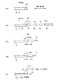
具体的には、移動プログラムが開始されると、まず高さ方向決定工程では、所定の高さ位置において載置台14を回転することによって、図5に示すように処理室4A(図1参照)内における3つの保持ピン部の内の1つの保持ピン部20を図6(A)に示すように搬入搬出側へ向ける第1の工程を行う(S1)。この搬入搬出側はゲート開口36(図1参照)を臨む方向である。この載置台14の回転角度、高さ位置はエンコーダ等により認識されている。
A teaching operation, which is a positioning method described below, is automatically executed based on a teaching movement program created in advance as described above.
[Height direction determination process]
Specifically, when the moving program is started, first, in the height direction determination step, the mounting table 14 is rotated at a predetermined height position, thereby processing
更に移動プログラムが実行されて、以下の一連の動作が順次行われる。すなわち、次に、第2の工程(S2)及び図6(B)に示すように、ピック部54を上記保持ピン部20に向けて少しずつ接近させつつ保持ピン部20を矢印70に示すように上下動させる。この動作をマッピングセンサ部64が保持ピン部20を検出するまで行う。尚、図6(B)以降は側面図を示している。この場合、ピック部54の高さ位置は、設計図等により予め安全性を見込んで仮の高さ方向基準位置を決めておく。
Further, the moving program is executed, and the following series of operations are sequentially performed. That is, next, as shown in the second step (S2) and FIG. 6B, the holding
ここでの動作は、ピック部54を僅かに前進(ピック部に接近)させては停止して、そこで保持ピン部20を上下動させるというステップをマッピングセンサ部64が検出するまで繰り返し行うことになる。この時の僅かずつの前進量は、上記保持ピン部20の半径方向の長さL2(図3(C)参照)よりも短い長さ、例えば5mm程度に決定する。尚、この場合、ピック部54を低速度で継続的に前進させながら、保持ピン部20を連続的に往復上下動させるようにして保持ピン部20を検出するようにしてもよい。
This operation is repeated until the
上述のようにマッピングセンサ部64が保持ピン部20を検出したならば、第3の工程では図6(C)に示すように保持ピン部20を検出した状態でマッピングセンサ部64が保持ピン部20を未検出になるまでピック部54を矢印72に示すように少しずつ後退させて未検出になったことに応答してピック部54を停止させる(S3)。
If the
このように未検出になったならば、第4の工程では図6(D)に示すようにピック部54を上記保持ピン部20の長さよりも小さい僅かな距離だけ矢印74に示すように前進させて保持ピン部54を検出させて再び検出した状態にする(S4)。この場合、上記保持ピン部20の長さは、上端突起24の長さL1(図3(C)参照)で例えば4mmであり、これよりも小さい僅かな前進距離は例えば2mm程度である。
If undetected in this way, in the fourth step, as shown in FIG. 6D, the
このようにマッピングセンサ部64が保持ピン部20を再度検出した状態になったならば、第5の工程では図6(E)に示すように、保持ピン部20を検出した状態でこの保持ピン部20を矢印76に示すように下方へ少しずつ移動させて保持ピン部20を未検出になったことに応答して保持ピン部20の上端エッジを検出(認識)する(S5)。すなわち、保持ピン部20が未検出になった時に保持ピン部20の上端突起24(図3(C)参照)の上端エッジを検出したことになる。
In this way, when the
そして、第6の工程では、この保持ピン部20の上端エッジを検出した時のピック部54(マッピングセンサ部64)の高さ位置に基づいて高さ方向基準位置が決定されることになる(S6)。すなわち、この上端エッジを検出したことによってピック部54と保持アーム18の保持ピン部20との高さ方向の位置関係が決定されることになる。ここで上記載置台14の保持ピン部20とゲート開口36の高さ方向の位置関係は予め精度良く調整されている。例えば載置台14の高さが5.0mmの時に、上記上端エッジの高さがゲート開口36の高さ方向の中央に位置するように予め精度良く調整されている。
In the sixth step, the height direction reference position is determined based on the height position of the pick section 54 (mapping sensor section 64) when the upper end edge of the holding
従って、上記ステップS5において、例えば上端エッジを検出した時の載置台14の高さが7.0mmであると仮定すると、その時のピック部54の高さ方向の位置は、ゲート開口36の高さ方向の中央よりも2mmだけ上方に位置していることが判る。従って、上記2mmだけ仮の高さ方向基準位置を補正して真の高さ方向基準位置が求められることになる。これにより、ピック部54が前進する際には、これがゲート開口36や載置台14の保持ピン部20と干渉することを防止することができる。
Accordingly, in step S5, assuming that the height of the mounting table 14 is 7.0 mm when the upper edge is detected, for example, the position in the height direction of the
[前進角度決定工程]
次に、前進角度決定工程では、まず図7の第21の工程(S21)に示すように、ピック部54を保持ピン部20から一旦離間(後退)させて保持ピン部20を未検出状態とし、その後、図8(A)に示すようにマッピングセンサ部64が保持ピン部20を検出するまでピック部54を矢印78に示すように保持ピン部20に向けて前進(接近)させる。この場合、先の高さ方向決定工程で保持ピン部20を検出する位置が判っているので、円滑にピック部54を前進させることができる。
[Advancing angle determination process]
Next, in the advance angle determination step, first, as shown in the 21st step (S21) of FIG. 7, the
また、ここではマッピングセンサ部64が保持ピン部20を検出したことに応答して、直ちにピック部54の前進を停止させるようにしてもよいし、或いは検出後、更に僅かな距離だけピック部54を前進させた後に止めるようにしてもよい。
Further, here, in response to the detection of the holding
次に図7の第22の工程(S22)に示すように、保持ピン部20を検出している状態で、図8(B)に示すように保持ピン部20を矢印79のように左右に回転(揺動)させて上記マッピングセンサ部64が上記保持ピン部20を検出しなくなった時の左右の回転角度θ1、θ2(図9参照)を求める。すなわち、保持アーム18を回転することにより、保持アーム18の端部にある保持ピン部20が左右に回転するので、マッピングセンサ部64の光路80を遮断していた保持ピン部20の先端が、この光路80から逸脱することになり、その時の回転角度θ1、θ2を求める。
Next, as shown in the 22nd step (S22) of FIG. 7, in the state where the holding
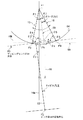
そして、次に図7の第23の工程(S23)に示すように、上記回転角度θ1、θ2に基づいて上記ピック部54の前進方向のずれ角度θx(図9参照)を求める。換言すれば、(θ1+θ2)/2の角度方向にピック部54の前進方向を一致(平行)させるようにする。この時の状況は図9に示されており、図9中においてX軸、Y軸は載置台14側の座標であり、点P1は保持ピン部20の回転中心(載置台14の回転中心)、点P2はピック部54の回転中心であり、ピック部54は前進方向82の先端にて直交する方向にマッピングセンサ部64の光路(光軸)80が通っている。
Then, as shown in a 23rd step (S23) of FIG. 7, a deviation angle θx (see FIG. 9) of the
保持アーム18の先端である保持ピン部20の回転軌跡84が上記光路80と交差する点が交差点P3、P4となり、それぞれが回転中心P1においてY軸となす角度が回転角度θ1、θ2となる。そして、線分86がX軸と平行で且つY軸と光路80との交点P5を通る直線であり、ピック部54の回転中心P2を通って上記線分86に直交する直線を線分88とする。従って、前進方向82と上記線分88とがなす角度がずれ角度θxを表している。また回転角度(θ1+θ2)の2等分線を線分89とする。
The points where the
そして、点P1、P3、P5がなす角度がθ3、点P3、P5、P1がなす角度がθ4、点P4、P5、P1がなす角度がθ5とすると、ずれ角度θxは次の式で表される。
θx=90−θ5
θ5=180−(θ3+θ2)
θ3=1/2×{180−(θ1+θ2)}
従って、”θx=(θ2−θ1)/2”となる。
このようにしてずれ角度θxを求めたならば、次に図7の第24の工程(S24)に示すように、上記ずれ角度θxに基づいてピック部54の前進角度を修正することになる。これにより、ピック部54の前進する方向が保持ピン部20及び載置台14の回転中心P1を通る方向、すなわち保持ピン部20を通る載置台14の半径方向と一致するようになる。
When the angle formed by the points P1, P3, and P5 is θ3, the angle formed by the points P3, P5, and P1 is θ4, and the angle formed by the points P4, P5, and P1 is θ5, the deviation angle θx is expressed by the following equation. The
θx = 90−θ5
θ5 = 180− (θ3 + θ2)
θ3 = ½ × {180− (θ1 + θ2)}
Therefore, “θx = (θ2−θ1) / 2”.
When the deviation angle θx is obtained in this way, the advance angle of the
[前進起点位置決定工程]
次に前進起点位置決定工程では、まず、図10の第31の工程(S31)に示すように、ピック部54を保持ピン部20から一旦離間(後退)させて保持ピン部20を未検出状態とし、その後、図11(A)に示すようにマッピングセンサ部64が保持ピン部20を検出するまでピック部54を矢印78に示すように保持ピン部20に向けて前進(接近)させる。この第31の工程は、先の第21の工程(S21)と全く同じである。
[Forward start position determination process]
Next, in the forward start position determination step, first, as shown in the thirty-first step (S31) of FIG. 10, the
次に、図10の第32の工程(S32)及び図11(B)に示すように、ピック部54を矢印90のように僅かな距離だけ後退させてマッピングセンサ部64が保持ピン部20を未検出の状態にする。この僅かな距離は、以下に記すようにピック部54を左右に回転した時に保持ピン部20を共に検出できる程度の距離であり、例えば数mm程度である。
Next, as shown in the thirty-second step (S32) of FIG. 10 and FIG. 11 (B), the
次に、図10の第33の工程(S33)及び図11(C)に示すように、ピック部54を矢印92のように左右に回転(揺動)することによってマッピングセンサ部64が保持ピン部20検出した時の左右の回転角度α1、α2を求める。すなわち、ピック部54を左右に回転するとにより、これに設けたマッピングセンサ部64の光路80上に保持ピン部20が侵入して光路80を遮断することになり、その時の回転角度α1、α2を求める。
Next, as shown in the thirty-third step (S33) of FIG. 10 and FIG. 11 (C), the
次に、図10の第34の工程(S34)及び図12に示すように、上記回転角度α1、α2に基づいて水平面内におけるピック部54のずれ量であるずれ水平距離Δhを求める。この時の状況を図12において模式的に示している。図12において、点Oはピック部54の回転中心であり、三角形ODEがピック部54を左右に回転する前の位置であり、辺DEがマッピングセンサ部64の光路を示す。
Next, as shown in the thirty-fourth step (S34) of FIG. 10 and FIG. 12, a displacement horizontal distance Δh, which is a displacement amount of the
また三角形OGHがピック部54を左に回転した時の状況を示し、三角形OIJがピック部54を右に回転した時の状況を示す。辺GH、IJはその時の光路を示し、点Cが保持ピン部20が光路を遮断した時の位置である。そして、ピック部54を左に回転させて保持ピン部20を検出した時の回転角度をα1で示し、ピック部54を右に回転させて保持ピン部20を検出した時の回転角度をα2で示している。そして、ピック部54の回転中心Oと点Fを通る線分と保持アーム18の延長方向、すなわち載置台の保持ピン部20を通る半径方向とのずれ量(距離)がずれ水平距離Δhとして示されている。
The triangle OGH shows the situation when the
ここで三角形OACと三角形OBCとは合同である。従って、線分OFと線分OCとが形成する微小角度Δxは以下のようになる。
Δx=(α2−α1)/2
この結果、ずれ水平距離Δhは、ピック部54の回転半径である線分OFの長さをRとした場合、以下の式のように求められる。
Δh=R×tanΔx
R:線分OFの長さ
Here, the triangle OAC and the triangle OBC are congruent. Therefore, the minute angle Δx formed by the line segment OF and the line segment OC is as follows.
Δx = (α2−α1) / 2
As a result, the deviation horizontal distance Δh is obtained by the following equation, where R is the length of the line segment OF which is the rotation radius of the
Δh = R × tanΔx
R: Length of line segment OF
このようにして、ずれ水平距離Δhを求めたならば、次に、図10の第35の工程(S35)に示すように、上記ずれ水平距離Δhだけピック部54の前進方向を平行移動させることによりピック部54の前進起点位置、すなわちピック部54の回転中心Oの位置を修正する。すなわち、回転中心Oをずれ水平距離ΔhだけX軸方向へ修正することになる。
これにより、ピック部54の前進する方向が、保持ピン部20及び載置台14の回転中心P1を通る方向と一致し、且つゲート開口36の横幅方向の中心部を通るようになる。
When the deviation horizontal distance Δh is obtained in this way, next, as shown in the thirty-fifth step (S35) of FIG. 10, the forward movement direction of the
As a result, the advancing direction of the
[前進量決定工程]
次に、前進量決定工程では、図13の第41の工程(S41)に示すように、先の第33の工程(S33)で求めた左右の回転角度α1、α2に基づいて保持ピン部20の座標を求める。ここでは座標上においてピック部54の前進方向と保持ピン部20を有する保持アーム18の長さ方向(半径方向)とが同一直線上に一致した状態となっている。
[Advance amount determination process]
Next, in the advance amount determination step, as shown in the forty-first step (S41) in FIG. 13, the holding
そして、図13の第42の工程(S42)に示すように、上記座標からピック部54の前進基準量を求めることになる。この場合、載置台14の回転中心に対する各保持アーム18の長さ及び各保持ピン部20の半径方向における取り付け位置は予め精度良く求められている。従って、ウエハWの中心を載置台14の中心に位置させるために必要なピック部54の前進量、すなわち前進すべき移動量は容易に計算により求めることができる。
Then, as shown in the forty-second step (S42) of FIG. 13, the forward reference amount of the
尚、上記ティーチング操作の説明では、ピック部54の前進方向と保持ピン部20を有する保持アーム18の長さ方向とを同一直線上に一致させた状態でピック部54を動作させるようにしたが、これに限定されず、他のティーチング操作も行うことができる。例えば前進角度決定工程で求めたずれ角θx(図9参照)と前進起点位置決定工程で求めたずれ水平距離Δhと左右の回転角度α1、α2(図12参照)とに基づいて保持ピン部20の座標が上述のように求まるので、この結果、載置台14の回転中心P1の座標(図9参照)を求めることができる。
In the description of the teaching operation, the
そして、この載置台14の回転中心P1に半導体ウエハWの中心を一致させるように搬送機構8(ピック部)のX方向及びY方向の各移動量を求めることで、ティーチングを行うことができる。この場合には、ピック部54の前進方向と保持ピン部20を有する保持アーム18の長さ方向とが同一直線上に一致しない状態でも搬送機構8をティーチングすることができる。
Then, teaching can be performed by determining each movement amount in the X direction and Y direction of the transport mechanism 8 (pick unit) so that the center of the semiconductor wafer W coincides with the rotation center P1 of the mounting table 14. In this case, the
以上のようなピック部54に対するティーチング操作は、全ての処理室4A〜4Cに対して行われることになる。また、他方のピック部56はマッピングセンサ部64を有していないが、両ピック部54、56は、互いに精度良く調整されているので、上記ピック部54に対する座標のデータは、他方のピック部56に対してもそのまま適用されることになる。以上のようにして求められた座標等の各種のデータ等は、ティーチングデータとしてシステム制御部66側に記憶され、実際のウエハの搬送時には、このティーチングデータを基にして搬送機構8により搬送されることになる。
The teaching operation for the
このようにして、ピック部54によりウエハWを搬送する時に、ウエハWをゲート開口36に干渉させることなく、載置台14上の適正な位置に精度良く載置することが可能となる。また、このティーチング操作に際しては、半導体ウエハを用いないので処理室の天井蓋を開閉する必要もなく迅速に、且つ容易に行うことが可能となる。
In this manner, when the wafer W is transferred by the
以上のように、搬送機構の位置決め方法の第1の発明によれば、ティーチング操作の作業性が向上して作業者間のバラツキを低減し、ピック部と被処理体とが干渉する危惧を抑制することが可能となる。 As described above, according to the first aspect of the positioning method of the transport mechanism, the workability of the teaching operation is improved, the variation between workers is reduced, and the risk of interference between the pick unit and the object to be processed is suppressed. It becomes possible to do.
<第2の発明>
次に、本発明の搬送機構の位置決め方法の第2の発明について説明する。先の第1の発明では、保持ピン部20に対してピック部54の相対位置関係を決定したが、この第2の発明では、保持ピン部20のみならず、中間ピン部22(図3参照)に対する相対位置関係を求めることにより、ティーチング操作を行うようにしている。
<Second invention>
Next, a second invention of the positioning method of the transport mechanism of the present invention will be described. In the first invention, the relative positional relationship of the
図14は搬送機構の位置決め方法の第2の発明の概略的な流れを示すフローチャート、図15は第2の発明の第1座標決定工程の内容を示すフローチャート、図16は第2の発明の第2の座標決定工程の内容を示すフローチャート、図17は第3の座標決定工程及び最終工程におけるピック部と保持アームとの位置関係を示す図である。 FIG. 14 is a flowchart showing a schematic flow of the second invention of the positioning method of the transport mechanism, FIG. 15 is a flowchart showing the contents of the first coordinate determining step of the second invention, and FIG. 16 is a flowchart of the second invention. FIG. 17 is a diagram showing the positional relationship between the pick portion and the holding arm in the third coordinate determination step and the final step.
まず、搬送機構の位置決め方法の第2の発明では、図14に示すように、先の第1の発明の高さ方向決定工程(図4参照)と同一内容を実施する高さ方向位置決定工程と、ピック部54の回転中心を起点とする保持ピン部20の座標である第1の座標を求める第1の座標決定工程と、ピック部54の回転中心を起点とする中間ピン部22の座標である第2の座標を求める第2の座標決定工程と、第1及び第2の座標に基づいて載置台14の回転中心の座標である第3の座標を求める第3の座標決定工程と、上記第1、第2及び第3の各座標に基づいてピック部54の前進角度と前進起点位置と前進基準量とを求める最終工程とを有しており、この順序で各工程を順次実施することになる。
First, in the second invention of the positioning method of the transport mechanism, as shown in FIG. 14, the height direction position determining step for carrying out the same contents as the height direction determining step (see FIG. 4) of the previous first invention. And a first coordinate determination step for obtaining a first coordinate which is a coordinate of the holding
[高さ位置決定工程]
上述のように、まず、高さ方向決定工程では、図5に示す第1の工程S1〜第6の工程S6(図6(A)〜図6(E))を先に説明したように順次行って、ピック部54の高さ方向の位置決めを行って真の高さ方向基準位置を求める。
[Height position determination process]
As described above, first, in the height direction determination step, the first step S1 to the sixth step S6 (FIGS. 6A to 6E) shown in FIG. 5 are sequentially performed as described above. Then, the true height direction reference position is obtained by positioning the
[第1の座標決定工程]
次に、第1の座標決定工程では、まず、図15の第41の工程に示すように、ピック部54を保持ピン部20から一旦離間(後退)させて保持ピン部20を未検出状態とし、その後、図11(A)に示すようにマッピングセンサ部64が保持ピン部20を検出するまでピック部54を矢印78に示すように保持ピン部20に向けて前進(接近)させる。この第41の工程は、先の第31の工程(S31)と全く同じである。
[First coordinate determination step]
Next, in the first coordinate determination step, first, as shown in the forty-first step of FIG. 15, the
次に、図15の第42の工程(S42)及び図11(B)に示すように、ピック部54を矢印90のように僅かな距離だけ後退させてマッピングセンサ部64が保持ピン部20を未検出状態にする。この第42の工程は、先の第32の工程(S32)と全く同じである。
Next, as shown in the forty-second step (S42) of FIG. 15 and FIG. 11B, the
次に、図15の第43の工程(S43)及び図11(C)に示すように、ピック部54を矢印92に示すように左右に回転(揺動)することによって、マッピングセンサ部64が保持ピン部20を検出した時の左右の回転角度α1、α2を求める。この第43の工程は、先の第33の工程(S33)と全く同じである。また、この時の回転角度α1、α2の状況は、図12において同様に示されている。
Next, as shown in the forty-third step (S43) and FIG. 11C of FIG. 15, the
次に、図15の第44の工程(S44)及び図12に示すように、上記左右の回転角度α1、α2に基づいて上記ピック部54の回転中心を起点とする保持ピン部20の座標である第1の座標を求める。先に説明したような内容から、ピック部54の回転中心Oと保持ピン部20の位置である点C(保持ピン部20が光路を遮断した位置)との線分OCの長さは以下のようになる。
Next, as shown in the forty-fourth step (S44) of FIG. 15 and FIG. 12, the coordinates of the holding
線分OC=線分OA/cos[(α1+α2)/2]
線分OA:ピック部54の長さ
上述のように線分OCの長さが求まり、また”ずれ角度Δx=(α2−α1)/2”であるので、保持ピン部20である点Cのピック部54の回転中心Oを起点(原点)とした座標1を求めることができる。
Line segment OC = Line segment OA / cos [(α1 + α2) / 2]
Line segment OA: Length of
[第2の座標決定工程]
次に、第2の座標決定工程では、図16のS51に示すように、中間ピン部22(図3(A)及び図3(B)参照)に対して、先の第41、第42、第43及び第44の各工程と同様な工程を順次行うことによって、この中間ピン部22の座標である第2の座標を求める。
[Second coordinate determination step]
Next, in the second coordinate determining step, as shown in S51 of FIG. 16, the intermediate pin portion 22 (see FIGS. 3A and 3B) is subjected to the 41st, 42nd, The second coordinate that is the coordinate of the
[第3の座標決定工程]
この第3の座標決定工程では、上述したように、上記第1及び第2の各座標に基づいて載置台14の回転中心、すなわち保持アーム18の回転中心の座標である第3の座標を求める。具体的には、図17に示すように、保持アーム18の先端の保持ピン部20の座標をX1、中間ピン部22の座標をX2とし、保持アーム18の回転中心P1の座標をX3とし、またピック部54の回転中心Oの座標を起点(0、0)、すなわち原点とする。
[Third coordinate determination step]
In the third coordinate determination step, as described above, the third coordinate, which is the coordinate of the rotation center of the mounting table 14, that is, the rotation center of the holding
ここで、保持ピン部20、中間ピン部22及び保持アーム18の回転中心P1は同一直線上に位置しており、しかも、回転中心P1と中間ピン部22との間の長さや回転中心P1と保持ピン部20との間の長さは先に正確に規定されている。従って、座標X3を上記関係から求めることができる。
Here, the rotation center P1 of the holding
[最終工程]
以上のようにして座標X3が求められると、座標X1、X2、X3とピック部54の回転中心Oの原点(0、0)との関係から、ピック部54の前進方向と保持アーム18の長さ方向とのずれ角度θx(図9参照)及びずれ水平距離Δh(図12参照)が求められるので、ピック部54の前進角度、前進起点位置及び前進基準量をそれぞれ修正して正確な値を設定することができる。このような一連のティーチング操作は、各処理室4A〜4Cに対して、同様に行われることになる。
[Final process]
When the coordinate X3 is obtained as described above, the forward direction of the
このように、この第2の発明においても、ティーチング操作の作業性が向上して作業者間のバラツキを低減し、ピック部と被処理体とが干渉する危惧を抑制することができる。 Thus, also in this 2nd invention, workability | operativity of teaching operation improves, the variation between workers can be reduced, and the concern that a pick part and a to-be-processed object may interfere can be suppressed.
<位置ずれ量算出方法>
次に、以上のようなティーチング操作により求められたティーチングデータに基づいて搬送された半導体ウエハの搬送精度がどの程度正確なのかを検証するための被処理体の位置ずれ量算出方法について図18乃至図22も参照して説明する。
<Position displacement calculation method>
Next, a method for calculating the amount of positional deviation of the object to be processed for verifying how accurate the transfer accuracy of the transferred semiconductor wafer is based on the teaching data obtained by the teaching operation as described above will be described with reference to FIGS. This will be described with reference to FIG.
図18は被処理体の位置ずれ量算出方法を説明する概略的な流れを示すフローチャート、図19は半導体ウエハのエッジと保持ピン部の上端突起との位置関係を説明する説明図、図20は半導体ウエハのエッジと上端突起との位置関係を求める時のピック部の動作を説明する説明図、図21は載置台の保持アームと半導体ウエハとの位置ずれ量を説明するための平面図、図22は位置ずれ量を算出する時の演算の一例を示す図である。尚、図1乃至図17において説明した構成部材と同一構成部材については同一参照符号を付して、その説明を省略する。 18 is a flowchart showing a schematic flow for explaining a method for calculating the amount of positional deviation of the object to be processed, FIG. 19 is an explanatory diagram for explaining the positional relationship between the edge of the semiconductor wafer and the upper end protrusion of the holding pin portion, and FIG. FIG. 21 is an explanatory diagram for explaining the operation of the pick unit when obtaining the positional relationship between the edge of the semiconductor wafer and the upper end protrusion, and FIG. 21 is a plan view for explaining the amount of positional deviation between the holding arm of the mounting table and the semiconductor wafer. FIG. 22 is a diagram illustrating an example of calculation when calculating the amount of displacement. The same components as those described in FIGS. 1 to 17 are denoted by the same reference numerals, and the description thereof is omitted.
この位置ずれ量検出方法は、ティーチング操作の直後だけでなく、運用されている搬送機構の搬送精度を評価する場合にも用いることが可能である。この被処理体の位置ずれ量算出方法は、図18に示すようにピック部を有する搬送機構を用いて上記被処理体を上記載置台に載置して支持させる載置工程S61と、上記搬送機構のピック部に設けた検出部により上記被処理体のエッジと上記保持ピン部の外周端に設けられた上端突起との位置関係を各保持ピン部について求める測定工程S62と、上記求めた位置関係に基づいて上記被処理体の位置ずれ量を求めるずれ量算出工程S63とを有する。 This positional deviation amount detection method can be used not only immediately after the teaching operation but also when evaluating the transport accuracy of the transport mechanism in operation. As shown in FIG. 18, the method of calculating the positional deviation amount of the object to be processed includes a mounting step S61 for mounting and supporting the object to be processed on the mounting table using a transport mechanism having a pick unit, and the transport. A measuring step S62 for obtaining the positional relationship between the edge of the object to be processed and the upper end protrusion provided on the outer peripheral end of the holding pin portion for each holding pin portion by the detecting portion provided in the pick portion of the mechanism, and the obtained position A deviation amount calculating step S63 for obtaining a positional deviation amount of the object to be processed based on the relationship.
[載置工程]
具体的には、上記載置工程では、前述のようにティーチング操作が完了した上記搬送機構8のピック部、例えばピック部54を用いて半導体ウエハWを先に記憶したティーチングデータに従って搬送し、載置台14に載置して支持させる。この際、載置台14の3本の保持アーム18の内の1本の保持アームをゲート開口36側に向けておく。この保持アーム18は前述したようにこの回転中心P1を中心としてその周方向に120度の等間隔で設けられており、その先端部に保持ピン部20が取り付けられている。
[Placement process]
Specifically, in the above placement step, the semiconductor wafer W is transported according to the previously stored teaching data using the pick unit of the
[測定工程]
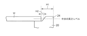
次に、測定工程では、検出部としてマッピングセンサ部64が設けられているピック部54を用いて、図19に示すようにウエハWのエッジと保持ピン部20の上端突起24との位置関係を測定して求める。ここで、図19に示すように上記位置関係は、ウエハWのエッジ(外周端)と上端突起24の外周端(外周面)との間の距離H1やウエハWのエッジと上端突起24の内周端(内周面)との間の距離H2を求めることになる。
[Measurement process]
Next, in the measurement process, the positional relationship between the edge of the wafer W and the
ここで上記距離H2は、ウエハWの厚さ方向のほぼ中央の高さレベルにおける距離であるが、この場合、上端突起24の内周端の面はテーパ面となっているので、距離H2の値は、高さレベル(上下方向の位置)が僅かに変化するだけで、測定時に容易に変動してしまうので安定していない。これに対して、上端突起24の外周端の面は上下方向に垂直な面になっているので、高さレベルが変化しても距離H1は安定した値となる。従って、上記位置関係としては、距離H1を求めるのが好ましい。以下の説明では、この距離H1を求める場合を例にとって説明する。
Here, the distance H2 is a distance at a height level substantially at the center in the thickness direction of the wafer W. In this case, the surface of the inner peripheral end of the
まず、この測定工程では、最初にマッピングセンサ部64(図2参照)を、図20(A)に示す軌跡100のように動かす。すなわち、マッピングセンサ部64をウエハWの例えば上方に水平方向から侵入させてエッジよりも十分に内側に位置させ、そして、このマッピングセンサ部64を下方へ降下させてウエハWを横切るようにする。
First, in this measurement step, first, the mapping sensor unit 64 (see FIG. 2) is moved as shown by a locus 100 shown in FIG. That is, the
これにより、マッピングセンサ部64の光路がウエハWの厚さ部分で遮断されるので、センサのオンオフが切り替わるポイントA、Bの高さ位置が検出される。従って、ポイントA、Bの部分の高さの中央の値、”(A+B)/2”が高さレベル102となる。上記の場合、マッピングセンサ部64をウエハWの下方に侵入させた後に、これを上方へ移動させるようにしてもよい。
Thereby, since the optical path of the
このように、ウエハWの高さレベル102を求めたならば、次に、上記距離H1を求める。この方法には、概略的には図20(B)〜図20(D)に示すように大きく3つの方法が存在する。尚、ウエハWの厚さは0.8mm程度である。
If the
図20(B)に示す第1の方法では、マッピングセンサ部64をウエハと同じ高さレベル102に沿って前進させて、その時にセンサのオンオフを検出することにより距離H1を求める。この第1の方法の場合には、迅速に距離H1を求めることができるが、実際の動作ではマッピングセンサ部64を設けてあるピック部54は、前進しながら僅かに上下に揺動することは避けられないので、誤検知する恐れも僅かに存在する。
In the first method shown in FIG. 20B, the
図20(C)に示す第2の方法では、マッピングセンサ部64を軌跡104に示すように上下方向へ大きく振りながら少しずつ前進させて行き、その時のセンサのオンオフを検出することにより距離H1を求める。この場合、測定対象箇所よりも十分に前の位置からマッピングセンサ部64の上下動を行う。この軌跡104に沿った移動は、例えば前進→下方移動→前進→上方移動→前進→下方移動→前進→…のように繰り返して行く。この際、前進時のピッチは、例えば0.1mm程度であり、上下方向への移動は例えば数mm程度である。尚、測定対象箇所でない部分を前進するには、上記ピッチに限定されず、その部分では前進移動量を長くして測定時間を短くするのがよい。
In the second method shown in FIG. 20C, the
この第2の方法の場合には、上記第1の方法よりも測定時間が長くなるが、ピック部54の上下の揺動に対して誤検出が生ずる恐れが少ないので、検出精度を向上させることができる。
In the case of the second method, the measurement time is longer than that of the first method, but there is less possibility of erroneous detection with respect to the vertical swing of the
図20(D)に示す第3の方法は、上記第1の方法と第2の方法を組み合わせたものであり、マッピングセンサ部64を軌跡106に示すように上下方向へ僅かに振りながら少しずつ前進させて行き、その時のセンサのオンオフを検出することにより距離H1を求める。この場合、マッピングセンサ部64をウエハWの高さレベル102を中心として僅かに上下動させる。この軌跡106に沿った移動は、例えば、前進→下方移動→前進→上方移動→前進→下方移動→前進→…のように繰り返して行く。
The third method shown in FIG. 20D is a combination of the first method and the second method described above. The
この際、前進時のピッチは、例えば0.1mm程度、高さレベル102を中心とした上下方向への移動は例えば±0.1mm程度である。尚、測定対象箇所でない部分を前進するには、上記ピッチに限定されず、その部分では前進移動量を長くして測定時間を短くするのがよい。
At this time, the forward pitch is, for example, about 0.1 mm, and the vertical movement around the
この第3の方法の場合には、第2の方法と同じような高い検出精度が得られ、しかも第2の方法よりも測定時間を大幅に短くすることができる。尚、上記第2の方法及び第3の方法において、上端突起24の外周端を検出する部分では、誤検出の恐れが少ないのでマッピングセンサ部付64を上下動させないで、高さレベル102に沿って水平に前進させるようにして検出するようにしてもよい。
In the case of the third method, high detection accuracy similar to that of the second method can be obtained, and the measurement time can be significantly shortened as compared with the second method. In the second method and the third method, there is less risk of erroneous detection at the portion where the outer peripheral edge of the
更に、図20(A)〜図20(D)で示した軌跡に沿って逆方向からマッピングセンサ部を移動させるようにしてもよい。この場合には、マッピングセンサ部は少しずつ後退することになる。また上記第1〜第3の方法は、距離H1の測定の一例を示したに過ぎず、これらに限定されない。 Furthermore, you may make it move a mapping sensor part from the reverse direction along the locus | trajectory shown to FIG. 20 (A)-FIG. 20 (D). In this case, the mapping sensor unit is moved back little by little. Moreover, the said 1st-3rd method only showed an example of the measurement of the distance H1, and is not limited to these.
以上のようにして、ある1箇所の保持ピック部20における距離H1を測定したならば、載置台14を120度回転させ、上述したと同様な方法で距離H1を求め、更に載置台14を120度回転させて上述したと同様な方法で距離H1を求めて、3箇所の保持ピック部20における各距離H1を求める。
When the distance H1 in one holding
ここで図21に示すように、3本の保持アーム18の各支持ピン部20で支持された半導体ウエハWの各支持ピン部20、すなわち第1支持ピン20−1、第2支持ピン20−2、第3支持ピン20−3において得られた測定値である各距離H1を、ウエハWの反時計回りに沿ってH11、H12、H13とする。
Here, as shown in FIG. 21, the
[ずれ量算出工程]
次に、ずれ量算出工程では、例えば以下に示すような演算によりウエハWの位置ずれ量を求める。ここでは、便宜上、平面内において直交する方向、すなわちX方向とY方向の2方向の位置ずれ量を求める。
[Deviation amount calculation process]
Next, in the deviation amount calculating step, the positional deviation amount of the wafer W is obtained by the following calculation, for example. Here, for the sake of convenience, the amount of displacement in two directions, that is, the direction orthogonal to the plane, that is, the X direction and the Y direction is obtained.
まず、ウエハWが載置台14の保持アーム18に支持されている状態において、ウエハWの中心と載置台14の回転中心P1が一致している場合のウエハエッジと保持ピン部20の上端突起24の外周端との間の距離H1の値は、設計値(適正値)Cとして予め求められており、上記測定値と設計値Cとの差がずれ量となる。この設計値Cは例えば5.5mm程度である。
First, in a state where the wafer W is supported by the holding
そして、上記設計値Cに基づいて各保持ピン部20におけるずれ量を求める。第1〜第3支持ピン部20−1〜20−3におけるずれ量Z1、Z2、Z3は以下のようになる。
Z1=H11−C
Z2=H12−C
Z3=H13−C
Based on the design value C, the amount of deviation in each holding
Z1 = H11-C
Z2 = H12-C
Z3 = H13-C
次に、位置ずれ量のX方向の成分XdとY方向Ydの成分とを求める。
Xd=(Z3×sin60°−Z1×sin60°)/2(図22(A)及び図22(B)参照)
Yd=Z2−Xd×tanα(図22(C)参照)
Next, a component Xd in the X direction and a component in the Y direction Yd of the positional deviation amount are obtained.
Xd = (Z3 ×
Yd = Z2−Xd × tan α (see FIG. 22C)
ここで”α=θ/2”である。
すなわち図22(C)において、以下のようになる。
θ=Asin(Xd/150)(尚、”Asin”は、アークサインである)。
また、”α+β=π/2”及び”π=θ+2β”であるので、上述のように”α=θ/2”となる。
以上のようにして位置ずれ量のX方向の成分XdとY方向の成分Ydが求められる。これにより、搬送機構により載置台に対して載置して支持させた被処理体の位置ずれ量を精度良く求めることができる。
Here, “α = θ / 2”.
That is, in FIG.
θ = Asin (Xd / 150) (“Asin” is an arc sine).
Further, since “α + β = π / 2” and “π = θ + 2β”, “α = θ / 2” as described above.
As described above, the X-direction component Xd and the Y-direction component Yd of the positional deviation amount are obtained. As a result, the amount of positional deviation of the object to be processed placed and supported on the placement table by the transport mechanism can be obtained with high accuracy.
このようにして求められた位置ずれ量の成分Xd、Ydは、システム制御部66(図1参照)に送られて、このシステム制御部66が有する図示しないディスプレイやプリンタ等に表示され、その評価結果を示すことになり、オペレータ等に認識させることになる。
The components Xd and Yd of the misregistration amount thus obtained are sent to the system control unit 66 (see FIG. 1) and displayed on a display or printer (not shown) included in the
また、上記評価結果の表示と共にシステム制御部66や記憶媒体68に記載されている先のティーチングデータに対して、上記位置ずれ量を相殺するように修正を加え、新たなティーチングデータとして記憶する。
In addition to the display of the evaluation result, the previous teaching data described in the
これにより、先のティーチングデータを微調整して搬送精度を向上させることが可能となる。また、このようなティーチングデータの評価や微修正は、プロセスの実施の途中(合間)に行うことにより、処理室内の熱等による構成部材の経時変化を確認し、これに対応することが可能となる。このように、被処理体を載置台に対して載置させるための搬送機構のティーチングデータを微調整して修正することにより搬送精度を向上させることができる。 As a result, the previous teaching data can be finely adjusted to improve the conveyance accuracy. In addition, such evaluation and fine correction of teaching data can be performed during the process (in the interval), so that it is possible to confirm and respond to changes over time in the components caused by heat in the processing chamber. Become. Thus, the conveyance accuracy can be improved by finely adjusting and correcting the teaching data of the conveyance mechanism for placing the object to be processed on the mounting table.
尚、ここで説明した処理システム2の構成は単に一例を示したに過ぎず、これらの構成に限定されないのは勿論である。また、ここでは被処理体として半導体ウエハを例にとって説明したが、この半導体ウエハにはシリコン基板やGaAs、SiC、GaNなどの化合物半導体基板も含まれ、更にはこれらの基板に限定されず、液晶表示装置に用いるガラス基板やセラミック基板等にも本発明を適用することができる。
It should be noted that the configuration of the
2 処理システム
4A〜4C 処理室
6 大気搬送室
8 搬送機構
14 載置台
16 回転支持軸
18 保持アーム
20 保持ピン部
22 中間ピン部
50 第1アーム
52 第2アーム
54,56 ピック部
60,62 載置パッド
64 マッピングセンサ部(検出部)
64A 発光素子
64B 受光素子
θx ずれ角度
Δh ずれ水平距離
W 半導体ウエハ(被処理体)
2
64A
Claims (19)
前記検出部によって前記保持ピン部の上端エッジを検出して前記ピック部の高さ基準位置を決定する高さ方向決定工程と、
前記保持ピン部を通る前記載置台の半径方向と前記ピック部の前進方向とのずれ角度を求めて前記ピック部の前進角度を修正する前進角度決定工程と、
前記保持ピン部を通る前記載置台の半径方向と前記ピック部の前進方向とのずれ水平距離を求めて前記ピック部の前進起点位置を修正する前進起点位置決定工程と、
前記保持ピン部の座標から前記ピック部の前進基準量を求める前進量決定工程と、
を有することを特徴とする搬送機構の位置決め方法。 It has a plurality of holding pin portions that hold the lower surface of the peripheral portion of the object to be processed, and can be moved toward and away from the mounting table that is capable of turning and moving up and down, and whether or not the object to be processed is present at the tip. In the positioning method of the transport mechanism having the pick part provided with the detection part to detect,
A height direction determining step of detecting an upper end edge of the holding pin portion by the detecting portion and determining a height reference position of the pick portion;
A forward angle determination step of correcting a forward angle of the pick part by obtaining a deviation angle between a radial direction of the mounting table and the forward direction of the pick part passing through the holding pin part;
A forward start position determination step of correcting a forward start position of the pick section by obtaining a horizontal distance between the radial direction of the mounting table and the forward direction of the pick section passing through the holding pin section;
Advance amount determination step for obtaining the advance reference amount of the pick portion from the coordinates of the holding pin portion;
A method for positioning a transport mechanism, comprising:
前記複数の保持ピン部の内の1つの保持ピン部を前記被処理体の搬入搬出側に向ける第1の工程と、
前記ピック部を前記保持ピン部に向けて少しずつ接近させつつ前記保持ピン部を上下動させることを前記検出部が前記保持ピン部を検出するまで行う第2工程と、
前記保持ピン部を検出した状態で前記検出部が前記保持ピン部を未検出になるまで前記ピック部を少しずつ後退させて未検出になったことに応答して停止させる第3の工程と、
前記ピック部を前記保持ピン部の長さよりも小さい僅かな距離だけ前進させて前記保持ピン部を検出した状態とする第4の工程と、
前記保持ピン部を検出した状態で前記保持ピン部を下方向へ移動させて前記保持ピン部を未検出になったことに応答して前記保持ピン部の上端エッジを検出する第5の工程と、
前記上端エッジを検出した高さ位置に基づいて高さ方向基準位置を決定する第6の工程と、
を有することを特徴とする請求項1記載の搬送機構の位置決め方法。 The height direction determining step includes
A first step of directing one holding pin portion of the plurality of holding pin portions toward the loading / unloading side of the object to be processed;
A second step of moving the holding pin part up and down while making the pick part approach the holding pin part little by little until the detection part detects the holding pin part;
A third step of stopping in response to the undetection by retreating the pick unit little by little until the detection unit becomes undetected while the detection pin is detected;
A fourth step of a state of the pick detects said support pin and smaller slight distance is advanced than the length of the support pin,
A fifth step of detecting an upper end edge of the holding pin portion in response to the detection of the holding pin portion being undetected by moving the holding pin portion downward with the holding pin portion detected; ,
A sixth step of determining a height direction reference position based on the height position at which the upper edge is detected;
The positioning method of the transport mechanism according to claim 1, wherein:
前記ピック部を前記保持ピン部から一旦離間させた後に、前記検出部が前記保持ピン部を検出するまで前記ピック部を前記保持ピン部に向けて前進させる第21の工程と、
前記保持ピン部を検出している状態で前記保持ピン部を左右に回転して前記検出部が前記保持ピン部を検出しなくなった時の左右の回転角度を求める第22の工程と、
前記回転角度に基づいて前記ピック部の前進方向の前記ずれ角度を求める第23の工程と、
前記ずれ角度に基づいて前記ピック部の前進角度を修正する第24の工程と、
を有することを特徴とする請求項1又は2記載の搬送機構の位置決め方法。 The advance angle determination step includes
A 21st step of moving the pick part forward toward the holding pin part until the detecting part detects the holding pin part after the pick part is once separated from the holding pin part;
A twenty-second step of obtaining a left and right rotation angle when the holding pin portion is detected by rotating the holding pin portion left and right while the holding pin portion is being detected;
A 23rd step of determining the deviation angle in the forward direction of the pick portion based on the rotation angle;
A twenty-fourth step of correcting the advance angle of the pick portion based on the deviation angle;
The method of positioning a transport mechanism according to claim 1, wherein:
前記ピック部を前記保持ピン部から一旦離間させた後に、前記検出部が前記保持ピン部を検出するまで前記ピック部を前記保持ピン部に向けて前進させる第31の工程と、
前記ピック部を僅かな距離だけ後退させて前記検出部が前記保持ピン部を未検出の状態にする第32の工程と、
前記ピック部を左右に回転することによって前記検出部が前記保持ピン部を検出した時の左右の回転角度を求める第33の工程と、
前記左右の回転角度に基づいて前記保持ピン部を通る前記載置台の半径方向と前記ピック部の前進方向との水平面内における前記ずれ水平距離を求める第34の工程と、
前記ずれ水平距離だけ前記ピック部の前進方向を平行移動させることにより前記ピック部の前記前進起点位置を修正する第35の工程と、
を有することを特徴とする請求項1乃至3のいずれか一項に記載の搬送機構の位置決め方法。 The forward start position determining step includes
A thirty-first step of moving the pick portion forward toward the holding pin portion until the detecting portion detects the holding pin portion after the pick portion is once separated from the holding pin portion;
A thirty-second step of retracting the pick part by a slight distance so that the detection part makes the holding pin part undetected;
A thirty-third step of obtaining left and right rotation angles when the detection unit detects the holding pin unit by rotating the pick unit left and right;
A thirty-fourth step of determining the horizontal displacement in the horizontal plane between the radial direction of the mounting table passing through the holding pin portion and the advancing direction of the pick portion based on the left and right rotation angles;
A thirty-fifth step of correcting the forward start position of the pick part by translating the forward direction of the pick part by the offset horizontal distance;
The positioning method for a transport mechanism according to any one of claims 1 to 3, wherein:
前記左右の回転角度に基づいて前記保持ピン部の座標を求める第41の工程と、
前記座標から前記ピック部の前記前進基準量を求める第42の工程と、
を有することを特徴とする請求項4記載の搬送機構の位置決め方法。 The advance amount determination step includes:
A forty-first step of obtaining coordinates of the holding pin portion based on the left and right rotation angles;
A forty second step for determining the forward reference amount of the pick portion from the coordinates;
The positioning method of the transport mechanism according to claim 4, comprising:
前記検出部によって前記保持ピン部の上端エッジを検出して前記ピック部の高さ基準位置を決定する高さ方向決定工程と、
前記ピック部の回転中心を起点とする前記保持ピン部の座標である第1の座標を求める第1の座標決定工程と、
前記ピック部の回転中心を起点とする前記中間ピン部の座標である第2の座標を求める第2の座標決定工程と、
前記第1及び第2の座標に基づいて前記載置台の回転中心の座標である第3の座標を求める第3の座標決定工程と、
前記第1、第2及び第3の座標に基づいて前記ピック部の前進角度と前進起点位置と前進基準量とを求める最終工程と、
を有することを特徴とする搬送機構の位置決め方法。 It has a plurality of holding pin portions for holding the lower surface of the peripheral portion of the object to be processed and a plurality of intermediate pin portions arranged on the inner peripheral side of the plurality of holding pin portions, and is capable of turning and moving up and down. In the positioning method of the transport mechanism having a pick unit provided with a detection unit that detects the presence or absence of an object to be processed at the tip, which can be moved closer to and away from the mounting table.
A height direction determining step of detecting an upper end edge of the holding pin portion by the detecting portion and determining a height reference position of the pick portion;
A first coordinate determination step for obtaining a first coordinate which is a coordinate of the holding pin portion starting from the rotation center of the pick portion;
A second coordinate determination step for obtaining a second coordinate which is a coordinate of the intermediate pin portion starting from the rotation center of the pick portion;
A third coordinate determination step for obtaining a third coordinate which is a coordinate of the rotation center of the mounting table based on the first and second coordinates;
A final step of determining a forward angle, a forward start position, and a forward reference amount of the pick unit based on the first, second, and third coordinates;
A method for positioning a transport mechanism, comprising:
前記複数の保持ピン部の内の1つの保持ピン部を前記被処理体の搬入搬出側に向ける第1の工程と、
前記ピック部を前記保持ピン部に向けて少しずつ接近させつつ前記保持ピン部を上下動させることを前記検出部が前記保持ピン部を検出するまで行う第2の工程と、
前記保持ピン部を検出した状態で前記検出部が前記保持ピン部を未検出になるまで前記ピック部を少しずつ後退させて未検出になったことに応答して停止させる第3の工程と、
前記ピック部を前記保持ピン部の長さよりも小さい僅かな距離だけ前進させて前記保持ピン部を検出した状態とする第4の工程と、
前記保持ピン部を検出した状態で前記保持ピン部を下方向へ移動させて前記保持ピン部を未検出になったことに応答して前記保持ピン部の上端エッジを検出する第5の工程と、
前記上端エッジを検出した高さ位置に基づいて高さ方向基準位置を決定する第6の工程と、
を有することを特徴とする請求項6記載の搬送機構の位置決め方法。 The height position determining step includes
A first step of directing one holding pin portion of the plurality of holding pin portions toward the loading / unloading side of the object to be processed;
A second step of moving the holding pin part up and down while gradually moving the pick part toward the holding pin part until the detection unit detects the holding pin part;
A third step of stopping in response to the undetection by retreating the pick unit little by little until the detection unit becomes undetected while the detection pin is detected;
A fourth step of a state of the pick detects said support pin and smaller slight distance is advanced than the length of the support pin,
A fifth step of detecting an upper end edge of the holding pin portion in response to the detection of the holding pin portion being undetected by moving the holding pin portion downward with the holding pin portion detected; ,
A sixth step of determining a height direction reference position based on the height position at which the upper edge is detected;
The positioning method of the transport mechanism according to claim 6, wherein:
前記ピック部を前記保持ピン部から一旦離間させた後に、前記検出部が前記保持ピン部を検出するまで前記ピック部を前記保持ピン部に向けて前進させる第41の工程と、
前記ピック部を僅かな距離だけ後退させて前記検出部が前記保持ピン部を未検出の状態にする第42の工程と、
前記ピック部を左右に回転することによって前記検出部が前記保持ピン部を検出した時の左右の回転角度を求める第43の工程と、
前記左右の回転角度に基づいて前記ピック部の回転中心を起点とする前記保持ピン部の前記第1の座標を求める第44の工程と、
を有することを特徴とする請求項6又は7記載の搬送機構の位置決め方法。 The first coordinate determination step includes:
Forty-first step of moving the pick part forward toward the holding pin part until the detecting part detects the holding pin part after the pick part is once separated from the holding pin part;
A forty-second process in which the pick unit is retracted by a small distance so that the detection unit makes the holding pin unit undetected;
A forty-third step of obtaining left and right rotation angles when the detection unit detects the holding pin unit by rotating the pick unit left and right;
A 44th step of determining the first coordinates of the holding pin portion starting from the rotation center of the pick portion based on the left and right rotation angles;
8. The method for positioning a transport mechanism according to claim 6 or 7, wherein:
前記中間ピン部に対して前記第41、第42、第43及び第44の各工程と同様な工程を行って前記中間ピン部の前記第2の座標を求めることを特徴とする請求項8記載の搬送機構の位置決め方法。 In the second coordinate determination step,
9. The second coordinates of the intermediate pin portion are obtained by performing the same steps as the 41st, 42nd, 43rd and 44th steps on the intermediate pin portion. Positioning method of the transport mechanism.
ピック部を有する搬送機構を用いて前記被処理体を前記載置台に載置して支持させる載置工程と、
前記搬送機構のピック部に設けた検出部により前記被処理体のエッジと前記保持ピン部の外周端に設けられた上端突起との位置関係を各保持ピン部について求める測定工程と、
前記求めた位置関係に基づいて前記被処理体の位置ずれ量を求めるずれ量算出工程と、
を有することを特徴とする被処理体の位置ずれ量算出方法。 In the method of calculating the amount of positional deviation of the object to be processed that is held on the mounting table that has a plurality of holding pin portions and that can be turned,
A placing step of placing and supporting the object to be treated on the placing table using a transport mechanism having a pick unit; and
A measurement step of obtaining a positional relationship between the edge of the object to be processed and an upper end protrusion provided on an outer peripheral end of the holding pin portion for each holding pin portion by a detection unit provided in the pick portion of the transport mechanism;
A deviation amount calculating step for obtaining a positional deviation amount of the object to be processed based on the obtained positional relationship;
A method of calculating a positional deviation amount of the object to be processed, comprising:
請求項11乃至18のいずれか一項に記載の被処理体の位置ずれ量算出方法を実行する工程と、
前記工程で求められた位置ずれ量を相殺するように前記ティーチングデータを修正する工程とを有することを特徴とする搬送機構のティーチングデータの修正方法。 In the method for correcting the teaching data of the transport mechanism,
A step of executing the positional deviation amount calculation method for the object to be processed according to any one of claims 11 to 18,
And correcting the teaching data so as to cancel out the amount of misalignment obtained in the step.
Priority Applications (3)
| Application Number | Priority Date | Filing Date | Title |
|---|---|---|---|
| JP2012279632A JP6040757B2 (en) | 2012-10-15 | 2012-12-21 | Positioning method of transport mechanism, method of calculating displacement amount of object to be processed, and correcting method of teaching data of transport mechanism |
| US14/043,725 US9541920B2 (en) | 2012-10-15 | 2013-10-01 | Method for positioning a transfer unit, method for calculating positional deviation amount of an object to be processed, and method for correcting teaching data of the transfer unit |
| KR1020130121877A KR101745045B1 (en) | 2012-10-15 | 2013-10-14 | Method for positioning a transfer unit, method for calculating positional deviation amount of an object to be processed, and method for correcting teaching data of the trasnfer unit |
Applications Claiming Priority (3)
| Application Number | Priority Date | Filing Date | Title |
|---|---|---|---|
| JP2012228077 | 2012-10-15 | ||
| JP2012228077 | 2012-10-15 | ||
| JP2012279632A JP6040757B2 (en) | 2012-10-15 | 2012-12-21 | Positioning method of transport mechanism, method of calculating displacement amount of object to be processed, and correcting method of teaching data of transport mechanism |
Publications (2)
| Publication Number | Publication Date |
|---|---|
| JP2014099576A JP2014099576A (en) | 2014-05-29 |
| JP6040757B2 true JP6040757B2 (en) | 2016-12-07 |
Family
ID=50476099
Family Applications (1)
| Application Number | Title | Priority Date | Filing Date |
|---|---|---|---|
| JP2012279632A Active JP6040757B2 (en) | 2012-10-15 | 2012-12-21 | Positioning method of transport mechanism, method of calculating displacement amount of object to be processed, and correcting method of teaching data of transport mechanism |
Country Status (3)
| Country | Link |
|---|---|
| US (1) | US9541920B2 (en) |
| JP (1) | JP6040757B2 (en) |
| KR (1) | KR101745045B1 (en) |
Families Citing this family (21)
| Publication number | Priority date | Publication date | Assignee | Title |
|---|---|---|---|---|
| KR101686032B1 (en) * | 2013-03-28 | 2016-12-13 | 가부시키가이샤 히다치 고쿠사이 덴키 | Substrate processing apparatus, method of manufacturing semiconductor device and non-transitory computer-readable recording medium |
| WO2016189740A1 (en) * | 2015-05-28 | 2016-12-01 | 株式会社安川電機 | Robot system, teaching jig and teaching method |
| JP6671993B2 (en) * | 2016-02-01 | 2020-03-25 | 東京エレクトロン株式会社 | Method of teaching substrate transfer position and substrate processing system |
| CN108780770B (en) * | 2016-03-04 | 2022-12-06 | 川崎重工业株式会社 | Substrate transfer device and method for teaching substrate transfer robot |
| JP6752061B2 (en) * | 2016-06-13 | 2020-09-09 | 東京エレクトロン株式会社 | Board transfer device and board transfer method |
| KR102397110B1 (en) * | 2016-06-13 | 2022-05-12 | 도쿄엘렉트론가부시키가이샤 | Substrate transfer device and substrate transfer method |
| CN106449500A (en) * | 2016-09-27 | 2017-02-22 | 天津华海清科机电科技有限公司 | Positioning assembly |
| KR101856875B1 (en) * | 2016-12-06 | 2018-05-10 | 에스케이실트론 주식회사 | Wafer carrier thickness measuring device |
| CN111052336B (en) * | 2017-09-01 | 2024-03-01 | 株式会社国际电气 | Substrate processing apparatus, semiconductor device manufacturing method, and recording medium |
| JP6966913B2 (en) * | 2017-09-29 | 2021-11-17 | 川崎重工業株式会社 | How to search for the rotation axis of the board transfer device and the board mounting part |
| JP6924112B2 (en) * | 2017-09-29 | 2021-08-25 | 川崎重工業株式会社 | A method for obtaining the positional relationship between the board transfer device and the board transfer robot and the board mounting portion. |
| JP7023094B2 (en) * | 2017-12-05 | 2022-02-21 | 日本電産サンキョー株式会社 | robot |
| CN111095517B (en) * | 2018-03-01 | 2024-07-09 | 株式会社国际电气 | Substrate processing device, method for manufacturing semiconductor device, and storage medium |
| KR101971824B1 (en) * | 2018-03-05 | 2019-04-23 | 캐논 톡키 가부시키가이샤 | Robot, Robot system, Manufacturing apparatus of device, Manufacturing method of device and Method for adjusting teaching positions |
| US10943805B2 (en) * | 2018-05-18 | 2021-03-09 | Applied Materials, Inc. | Multi-blade robot apparatus, electronic device manufacturing apparatus, and methods adapted to transport multiple substrates in electronic device manufacturing |
| US10867821B2 (en) * | 2018-09-11 | 2020-12-15 | Kawasaki Jukogyo Kabushiki Kaisha | Substrate transfer robot and method of teaching edge position of target body |
| JP7158238B2 (en) * | 2018-10-10 | 2022-10-21 | 東京エレクトロン株式会社 | Substrate processing system |
| US11626305B2 (en) * | 2019-06-25 | 2023-04-11 | Applied Materials, Inc. | Sensor-based correction of robot-held object |
| KR102259067B1 (en) * | 2019-08-27 | 2021-05-31 | 세메스 주식회사 | Substrate Processing Apparatus and Substrate Transfer Method |
| JP7433180B2 (en) * | 2020-09-23 | 2024-02-19 | 東京エレクトロン株式会社 | Teaching method for transport device and robot arm |
| JP7614709B2 (en) * | 2021-03-19 | 2025-01-16 | 株式会社ディスコ | Conveyor |
Family Cites Families (15)
| Publication number | Priority date | Publication date | Assignee | Title |
|---|---|---|---|---|
| JPH0864654A (en) * | 1994-08-22 | 1996-03-08 | Dainippon Screen Mfg Co Ltd | Method and apparatus for transferring substrate |
| US5980195A (en) * | 1996-04-24 | 1999-11-09 | Tokyo Electron, Ltd. | Positioning apparatus for substrates to be processed |
| JPH11349280A (en) * | 1998-06-05 | 1999-12-21 | Shinko Electric Co Ltd | Suspended transfer device |
| JP2000208589A (en) | 1998-11-09 | 2000-07-28 | Tokyo Electron Ltd | Processing equipment |
| TW418429B (en) | 1998-11-09 | 2001-01-11 | Tokyo Electron Ltd | Processing apparatus |
| JP2001332604A (en) * | 2000-05-25 | 2001-11-30 | Nec Kyushu Ltd | Mechanism for detecting positioning error of carriage |
| JP4243937B2 (en) * | 2001-11-02 | 2009-03-25 | 東京エレクトロン株式会社 | Method for detecting support position of substrate support pin, method for detecting tilt thereof, teaching apparatus therefor, and teaching jig |
| JP4260423B2 (en) * | 2002-05-30 | 2009-04-30 | ローツェ株式会社 | Disc-shaped object reference position teaching method, positioning method, and transport method, and disc-shaped reference position teaching apparatus, positioning apparatus, transport apparatus, and semiconductor manufacturing equipment using these methods |
| US7361920B2 (en) | 2004-12-24 | 2008-04-22 | Tokyo Electron Limited | Substrate processing apparatus and transfer positioning method thereof |
| JP4468159B2 (en) | 2004-12-24 | 2010-05-26 | 東京エレクトロン株式会社 | Substrate processing apparatus and transfer position alignment method thereof |
| JP5336184B2 (en) | 2005-07-11 | 2013-11-06 | ブルックス オートメーション インコーポレイテッド | Automatic alignment board transfer device |
| US7907289B2 (en) * | 2007-09-13 | 2011-03-15 | Horiba, Ltd. | Substrate measuring stage |
| TW201005825A (en) * | 2008-05-30 | 2010-02-01 | Panasonic Corp | Plasma processing apparatus and method |
| US9111978B2 (en) * | 2009-04-13 | 2015-08-18 | Hirata Corporation | Substrate carrier measuring jig, collision preventing jig, and collision preventing method using the collision preventing jig |
| JP5516482B2 (en) * | 2011-04-11 | 2014-06-11 | 東京エレクトロン株式会社 | Substrate transport method, substrate transport apparatus, and coating and developing apparatus |
-
2012
- 2012-12-21 JP JP2012279632A patent/JP6040757B2/en active Active
-
2013
- 2013-10-01 US US14/043,725 patent/US9541920B2/en active Active
- 2013-10-14 KR KR1020130121877A patent/KR101745045B1/en active Active
Also Published As
| Publication number | Publication date |
|---|---|
| US9541920B2 (en) | 2017-01-10 |
| JP2014099576A (en) | 2014-05-29 |
| KR20140048052A (en) | 2014-04-23 |
| KR101745045B1 (en) | 2017-06-08 |
| US20140107825A1 (en) | 2014-04-17 |
Similar Documents
| Publication | Publication Date | Title |
|---|---|---|
| JP6040757B2 (en) | Positioning method of transport mechanism, method of calculating displacement amount of object to be processed, and correcting method of teaching data of transport mechanism | |
| US11908721B2 (en) | Tool auto-teach method and apparatus | |
| JP4697192B2 (en) | Position shift detection device and processing system using the same | |
| JP6918770B2 (en) | On-the-fly automatic wafer centering method and equipment | |
| JP4674705B2 (en) | Transport position adjusting method and transport system of transport system | |
| JP4254116B2 (en) | Substrate for alignment | |
| JP4239572B2 (en) | Transport position adjusting method and processing system of transport system | |
| JP5573861B2 (en) | Transport system | |
| TWI676232B (en) | Position detecting method of substrate transfer mechanism, position detecting device of memory medium and substrate transfer mechanism | |
| US20100008688A1 (en) | Method for aligning transfer position of transfer system | |
| JP6285275B2 (en) | Substrate processing apparatus and substrate processing method | |
| KR100779774B1 (en) | Device for correcting reference position for transfer mechanism, and correction method | |
| WO2005093821A1 (en) | Vertical heat treating apparatus and automatic teaching method for transfer mechanism | |
| JP6063776B2 (en) | Substrate transport path determination method, substrate transport apparatus, substrate processing apparatus, and program | |
| JP2005093807A (en) | Semiconductor manufacturing device | |
| JP2007123556A (en) | Vacuum processing method or vacuum processing equipment | |
| JP2014075397A (en) | Positioning method of transfer mechanism | |
| US9803924B2 (en) | Vertical heat treatment apparatus | |
| JP2006351883A (en) | Substrate transport mechanism and processing system | |
| US12387954B2 (en) | Teaching method for transfer device, and transfer system | |
| WO2026004139A1 (en) | Substrate processing device, teaching method for transfer machine, production method for semiconductor device, substrate transfer system, and program | |
| TW202522667A (en) | Substrate processing device and substrate transport method |
Legal Events
| Date | Code | Title | Description |
|---|---|---|---|
| A621 | Written request for application examination |
Free format text: JAPANESE INTERMEDIATE CODE: A621 Effective date: 20150830 |
|
| A977 | Report on retrieval |
Free format text: JAPANESE INTERMEDIATE CODE: A971007 Effective date: 20160721 |
|
| A131 | Notification of reasons for refusal |
Free format text: JAPANESE INTERMEDIATE CODE: A131 Effective date: 20160802 |
|
| A521 | Request for written amendment filed |
Free format text: JAPANESE INTERMEDIATE CODE: A523 Effective date: 20160812 |
|
| TRDD | Decision of grant or rejection written | ||
| A01 | Written decision to grant a patent or to grant a registration (utility model) |
Free format text: JAPANESE INTERMEDIATE CODE: A01 Effective date: 20161011 |
|
| A61 | First payment of annual fees (during grant procedure) |
Free format text: JAPANESE INTERMEDIATE CODE: A61 Effective date: 20161024 |
|
| R150 | Certificate of patent or registration of utility model |
Ref document number: 6040757 Country of ref document: JP Free format text: JAPANESE INTERMEDIATE CODE: R150 |
|
| R250 | Receipt of annual fees |
Free format text: JAPANESE INTERMEDIATE CODE: R250 |
|
| R250 | Receipt of annual fees |
Free format text: JAPANESE INTERMEDIATE CODE: R250 |
|
| R250 | Receipt of annual fees |
Free format text: JAPANESE INTERMEDIATE CODE: R250 |
|
| R250 | Receipt of annual fees |
Free format text: JAPANESE INTERMEDIATE CODE: R250 |
|
| R250 | Receipt of annual fees |
Free format text: JAPANESE INTERMEDIATE CODE: R250 |
|
| R250 | Receipt of annual fees |
Free format text: JAPANESE INTERMEDIATE CODE: R250 |
|
| R250 | Receipt of annual fees |
Free format text: JAPANESE INTERMEDIATE CODE: R250 |