JP6031006B2 - Terminal fitting connection structure and rotation fitting type connector - Google Patents
Terminal fitting connection structure and rotation fitting type connector Download PDFInfo
- Publication number
- JP6031006B2 JP6031006B2 JP2013139097A JP2013139097A JP6031006B2 JP 6031006 B2 JP6031006 B2 JP 6031006B2 JP 2013139097 A JP2013139097 A JP 2013139097A JP 2013139097 A JP2013139097 A JP 2013139097A JP 6031006 B2 JP6031006 B2 JP 6031006B2
- Authority
- JP
- Japan
- Prior art keywords
- terminal fitting
- contact
- terminal
- fitting
- central axis
- Prior art date
- Legal status (The legal status is an assumption and is not a legal conclusion. Google has not performed a legal analysis and makes no representation as to the accuracy of the status listed.)
- Active
Links
- 239000002184 metal Substances 0.000 claims description 79
- 238000010586 diagram Methods 0.000 description 9
- 230000004323 axial length Effects 0.000 description 8
- 230000008878 coupling Effects 0.000 description 8
- 238000010168 coupling process Methods 0.000 description 8
- 238000005859 coupling reaction Methods 0.000 description 8
- 238000002788 crimping Methods 0.000 description 8
- 230000002093 peripheral effect Effects 0.000 description 7
- 238000005452 bending Methods 0.000 description 5
- 238000012856 packing Methods 0.000 description 5
- 239000004020 conductor Substances 0.000 description 4
- 230000007423 decrease Effects 0.000 description 4
- 230000013011 mating Effects 0.000 description 3
- 239000007787 solid Substances 0.000 description 3
- 230000000694 effects Effects 0.000 description 2
- 238000003780 insertion Methods 0.000 description 2
- 230000037431 insertion Effects 0.000 description 2
- 238000009434 installation Methods 0.000 description 2
- 238000000465 moulding Methods 0.000 description 2
- 238000005549 size reduction Methods 0.000 description 2
- 230000007704 transition Effects 0.000 description 2
- 230000005489 elastic deformation Effects 0.000 description 1
- 230000006872 improvement Effects 0.000 description 1
- 239000000463 material Substances 0.000 description 1
- 238000000034 method Methods 0.000 description 1
- 238000003825 pressing Methods 0.000 description 1
- 230000009466 transformation Effects 0.000 description 1
Images


Classifications
-
- H—ELECTRICITY
- H01—ELECTRIC ELEMENTS
- H01R—ELECTRICALLY-CONDUCTIVE CONNECTIONS; STRUCTURAL ASSOCIATIONS OF A PLURALITY OF MUTUALLY-INSULATED ELECTRICAL CONNECTING ELEMENTS; COUPLING DEVICES; CURRENT COLLECTORS
- H01R13/00—Details of coupling devices of the kinds covered by groups H01R12/70 or H01R24/00 - H01R33/00
- H01R13/40—Securing contact members in or to a base or case; Insulating of contact members
- H01R13/42—Securing in a demountable manner
-
- H—ELECTRICITY
- H01—ELECTRIC ELEMENTS
- H01R—ELECTRICALLY-CONDUCTIVE CONNECTIONS; STRUCTURAL ASSOCIATIONS OF A PLURALITY OF MUTUALLY-INSULATED ELECTRICAL CONNECTING ELEMENTS; COUPLING DEVICES; CURRENT COLLECTORS
- H01R24/00—Two-part coupling devices, or either of their cooperating parts, characterised by their overall structure
- H01R24/005—Two-part coupling devices, or either of their cooperating parts, characterised by their overall structure requiring successive relative motions to complete the coupling, e.g. bayonet type
-
- H—ELECTRICITY
- H01—ELECTRIC ELEMENTS
- H01R—ELECTRICALLY-CONDUCTIVE CONNECTIONS; STRUCTURAL ASSOCIATIONS OF A PLURALITY OF MUTUALLY-INSULATED ELECTRICAL CONNECTING ELEMENTS; COUPLING DEVICES; CURRENT COLLECTORS
- H01R35/00—Flexible or turnable line connectors, i.e. the rotation angle being limited
- H01R35/04—Turnable line connectors with limited rotation angle with frictional contact members
-
- H—ELECTRICITY
- H01—ELECTRIC ELEMENTS
- H01R—ELECTRICALLY-CONDUCTIVE CONNECTIONS; STRUCTURAL ASSOCIATIONS OF A PLURALITY OF MUTUALLY-INSULATED ELECTRICAL CONNECTING ELEMENTS; COUPLING DEVICES; CURRENT COLLECTORS
- H01R4/00—Electrically-conductive connections between two or more conductive members in direct contact, i.e. touching one another; Means for effecting or maintaining such contact; Electrically-conductive connections having two or more spaced connecting locations for conductors and using contact members penetrating insulation
- H01R4/28—Clamped connections, spring connections
- H01R4/48—Clamped connections, spring connections utilising a spring, clip, or other resilient member
-
- H—ELECTRICITY
- H01—ELECTRIC ELEMENTS
- H01R—ELECTRICALLY-CONDUCTIVE CONNECTIONS; STRUCTURAL ASSOCIATIONS OF A PLURALITY OF MUTUALLY-INSULATED ELECTRICAL CONNECTING ELEMENTS; COUPLING DEVICES; CURRENT COLLECTORS
- H01R13/00—Details of coupling devices of the kinds covered by groups H01R12/70 or H01R24/00 - H01R33/00
- H01R13/62—Means for facilitating engagement or disengagement of coupling parts or for holding them in engagement
- H01R13/627—Snap or like fastening
- H01R13/6278—Snap or like fastening comprising a pin snapping into a recess
-
- H—ELECTRICITY
- H01—ELECTRIC ELEMENTS
- H01R—ELECTRICALLY-CONDUCTIVE CONNECTIONS; STRUCTURAL ASSOCIATIONS OF A PLURALITY OF MUTUALLY-INSULATED ELECTRICAL CONNECTING ELEMENTS; COUPLING DEVICES; CURRENT COLLECTORS
- H01R2101/00—One pole
Landscapes
- Details Of Connecting Devices For Male And Female Coupling (AREA)
Description
本発明は、端子金具の接続構造、及び当該端子金具の接続構造により端子金具相互を導通接続させる回転嵌合式コネクタに関する。 The present invention relates to a terminal fitting connection structure, and a rotary fitting connector that connects terminal fittings in a conductive manner by the terminal fitting connection structure.
図29は下記特許文献1に開示された端子金具の接続構造を示し、図30は下記特許文献2に開示された端子金具の接続構造を示している。
FIG. 29 shows a terminal fitting connection structure disclosed in
特許文献1の端子金具の接続構造は、第1端子金具110に装備されている接触用ばね片111を、第2端子金具120に装備されている接触面121に押圧接触させることで、第1端子金具110と第2端子金具120とを導通接続状態にする。
The connection structure of the terminal metal fittings of
特許文献1における第1端子金具110は、金属板のプレス成形により形成される雌型の端子金具で、電線を圧着接続する電線接続部112と、雄型の端子金具の先端部が嵌合する角筒状の嵌合部113と、を備えている。角筒状の嵌合部113は、下壁部114の前端から角筒の内部に折り返して当該第1端子金具110の軸方向に延在する前記接触用ばね片111と、該接触用ばね片111に対向する上壁部115とで、雄型の端子金具の先端部を挟持する。接触用ばね片111には、接触面121に接触する接点部111aが隆起形成されている。
The 1st terminal metal fitting 110 in
特許文献1における第2端子金具120は、金属板のプレス成形により形成される雄型の端子金具で、電線を圧着接続する電線接続部122と、第1端子金具110の嵌合部113に挿入される舌片状の先端部123と、を有している。そして、舌片状の先端部123の表面が、接触用ばね片111を押圧接触させる接触面121となっている。
The second terminal fitting 120 in
特許文献2の端子金具の接続構造は、第1端子金具130に装備されている接触用ばね片131を、第2端子金具140に装備されている接触面141に押圧接触させることで、第1端子金具130と第2端子金具140とを導通接続状態にする。
The connection structure of the terminal metal fitting of
特許文献2における第1端子金具130は、雌型の端子金具で、電線を圧着接続する略円筒状のバレル部132と、雄型の端子金具の先端部が嵌合する略円筒状の嵌合部133と、を備えている。嵌合部133は、円筒の周方向に離間する4箇所にすり割り134を形成したものである。すり割り134で分割されて第1端子金具130の軸方向に延在する周壁部が、円筒の径方向に撓み変形可能な接触用ばね片131として機能する。接触用ばね片131として機能する各周壁部の内面には、接触面141に接触する接点部131aが隆起形成されている。
The first terminal fitting 130 in
特許文献2における第2端子金具140は、雄型の端子金具で、電線を圧着接続する略円筒状のバレル部142と、第1端子金具130の嵌合部133に挿入される丸棒状の先端部143と、を有している。先端部143の外周面が、接触用ばね片131を押圧接触させる接触面141となっている。
The second terminal metal fitting 140 in
ところが、特許文献1及び特許文献2の何れの端子金具の接続構造の場合も、接触用ばね片111が、端子金具の軸方向に延在している。そのため、接触用ばね片111に安定した撓み性能を確保するために、接触用ばね片111に十分な長さを確保しようとすると、端子金具の軸方向長さが長大化し、端子金具の大型化や、当該端子金具を収容するコネクタの大型化を招くという問題があった。
However, in any of the terminal metal connection structures of
また、特許文献1及び特許文献2の何れの端子金具の接続構造の場合も、接触面121,141と接点部111a,131aとの間の接触面積が小さいため、端子金具相互の接触部における導体抵抗を下げることが難しいという問題があった。
Further, in any of the connection structures of the terminal fittings of
そこで、本発明の目的は、上記課題を解消することに係り、端子金具の軸方向長さを短縮して、当該端子金具を収容するコネクタの小型化を図ることができ、また、端子金具相互の接触部における導体抵抗を下げて電気的な接続の信頼性を向上させることのできる端子金具の接続構造を提供することにある。また、当該端子金具の接続構造により端子金具相互を導通接続させて、小型化を実現することのできる回転嵌合式コネクタを提供することにある。 Accordingly, an object of the present invention is to solve the above-mentioned problems, and by reducing the axial length of the terminal fitting, it is possible to reduce the size of the connector that accommodates the terminal fitting. It is an object of the present invention to provide a terminal fitting connection structure capable of lowering the conductor resistance at the contact portion and improving the reliability of electrical connection. Another object of the present invention is to provide a rotary fitting connector that can be miniaturized by electrically connecting the terminal fittings with the connection structure of the terminal fittings.
本発明の前述した目的は、下記の構成により達成される。
(1) 第1端子金具に装備されている接触用ばね片を、第2端子金具に装備されている接触面に押圧接触させることで、前記第1端子金具と前記第2端子金具とを導通接続状態にする端子金具の接続構造であって、
前記第1端子金具は、該第1端子金具の中心軸上に延在すると共に基端には前記第1端子金具の中心軸と略同軸に電線が接続される第1端子本体と、該第1端子本体の先端に前記第1端子金具の中心軸と同心の環状に形成された第1環状部と、該第1環状部の外周上で前記第1環状部の周方向に一定の間隔で並ぶ複数箇所に装備される複数の前記接触用ばね片と、を備えると共に、前記接触用ばね片は、前記第1環状部の外周から前記第1環状部の径方向外方に向かって延出したバネ支持部と、該バネ支持部から前記第1環状部の外周に沿って延出して先端側が前記第1端子金具の前記中心軸方向に変位可能な弾性片と、前記第1環状部の先端よりも相手端子側に突出した状態に前記弾性片に突出形成された接点用突部と、を備え、
前記第2端子金具は、該第2端子金具の中心軸上に延在すると共に基端には前記第2端子金具の前記中心軸と略同軸に電線が接続される第2端子本体と、前記第1端子金具の前記第1環状部と同一の環状で前記第2端子金具の前記中心軸と同心に前記第2端子本体の先端に設けられた第2環状部と、前記第1端子金具における複数の前記接点用突部と同じ間隔で前記第2環状部の外周に該第2環状部の径方向外方に向かって突設された複数の前記接触面と、隣接する前記接触面間に位置して前記接点用突部が没入可能な複数の接点逃がし部と、を備えた、
ことを特徴とする端子金具の接続構造。
The above-described object of the present invention is achieved by the following configuration.
(1) Conducting electrical connection between the first terminal fitting and the second terminal fitting by bringing the contact spring piece provided on the first terminal fitting into contact with the contact surface provided on the second terminal fitting. A connection structure for terminal fittings to be connected,
The first terminal fitting extends on the central axis of the first terminal fitting, and has a first terminal main body having a proximal end connected to an electric wire substantially coaxially with the central axis of the first terminal fitting, A first annular portion formed annularly concentrically with the central axis of the first terminal fitting at a tip of one terminal main body, and at a constant interval in a circumferential direction of the first annular portion on an outer periphery of the first annular portion; A plurality of the contact spring pieces provided at a plurality of positions, and the contact spring pieces extend from the outer periphery of the first annular portion toward the radially outer side of the first annular portion. A spring support portion, an elastic piece extending from the spring support portion along the outer periphery of the first annular portion, and having a distal end side that is displaceable in the central axis direction of the first terminal fitting, and the first annular portion A protrusion for contact formed to protrude from the elastic piece in a state protruding to the counterpart terminal side from the tip,
The second terminal fitting extends on a central axis of the second terminal fitting, and a second terminal main body having a proximal end connected to an electric wire substantially coaxially with the central axis of the second terminal fitting; A second annular portion provided at the tip of the second terminal body in the same annular shape as the first annular portion of the first terminal fitting and concentrically with the central axis of the second terminal fitting; and in the first terminal fitting A plurality of contact surfaces projecting radially outward of the second annular portion on the outer periphery of the second annular portion at the same interval as the plurality of contact projections, and between the adjacent contact surfaces A plurality of contact relief portions that are positioned and into which the protrusions for contact can be immersed,
This is a terminal metal connection structure.
(2) 前記第2端子金具の複数の前記接触面には、該接触面上に乗り上げた前記接点用突部が嵌合する凹み部が備えられたことを特徴とする上記(1)に記載の端子金具の接続構造。 (2) The plurality of contact surfaces of the second terminal metal fitting are provided with recesses into which the contact protrusions riding on the contact surfaces are fitted. Terminal fitting connection structure.
(3) 前記第2端子金具の複数の前記接触面の前記接点逃がし部に臨む一側縁には、前記接点逃がし部に没入している前記接点用突部を前記接触面上に誘導する傾斜面が設けられたことを特徴とする上記(1)又は(2)に記載の端子金具の接続構造。 (3) An inclination that guides the protrusion for contact, which is immersed in the contact relief portion, onto the contact surface at one side edge facing the contact relief portion of the plurality of contact surfaces of the second terminal metal fitting. The terminal metal connection structure according to the above (1) or (2), wherein a surface is provided.
(4) 前記第1端子金具に装備されている複数の前記接点用突部の一部は、他の前記接点用突部とはタイミングをずらして前記第2端子金具の接触面に乗り上げるように、前記接点用突部及び前記接触面の配置が設定されていることを特徴とする上記(1)〜(3)の何れか一つに記載の端子金具の接続構造。 (4) A part of the plurality of contact projections provided on the first terminal fitting may run on the contact surface of the second terminal fitting at a different timing from the other contact projections. The terminal fitting connection structure according to any one of (1) to (3), wherein an arrangement of the contact protrusions and the contact surface is set.
(5) 上記(1)〜(4)の何れか一つに記載の端子金具の接続構造を利用して端子金具相互を導通接続状態にする回転式コネクタであって、
中心軸上に前記第1端子金具を固定支持すると共に固定支持した前記第1端子金具の先端部が前端に露出し、前記中心軸と同心の円形断面である第1ハウジング本体と、該第1ハウジング本体に径方向に沿って突設された連結用ピンと、を備えた第1コネクタハウジングと、
中心軸上に前記第2端子金具を固定支持すると共に固定支持した前記第2端子金具の先端部が前端に露出し、前記中心軸と同心の円形断面であり前記第1ハウジング本体が嵌合する第2ハウジング本体と、前記第2ハウジング本体の前記第1コネクタハウジング側の端部から前記第2ハウジング本体の中心軸方向に沿って延在するように切欠形成されて前記第2ハウジング本体に前記第1ハウジング本体を前記第2ハウジング本体の中心軸方向に沿って嵌合させたときに前記連結用ピンが進入する軸方向溝と、該軸方向溝の終端から前記第2ハウジング本体の周方向の一側に前記周方向に沿って所定の長さに延設されて前記第1ハウジング本体と前記第2ハウジング本体とを相対回転させたときに前記連結用ピンが移動する周方向溝と、前記連結用ピンが前記周方向溝の終端に到達したときに前記周方向溝の始端側から前記連結用ピンに接触して前記連結用ピンの戻り方向への移動を規制することでコネクタハウジング相互の結合状態をロックするロック部と、を備えた第2コネクタハウジングと、
を備えたことを特徴とする回転式コネクタ。
(5) A rotary connector that uses the terminal metal fitting connection structure according to any one of the above (1) to (4) to bring the terminal metal fittings into a conductive connection state,
A first housing main body having a circular cross section concentric with the central axis, the front end of the first terminal metal fitting fixedly supported on the central axis and exposed at the front end. A first connector housing comprising a connecting pin projecting radially from the housing body;
The second terminal fitting is fixedly supported on the central axis and the tip of the second terminal fitting fixedly supported is exposed at the front end, and has a circular cross section concentric with the central axis and the first housing body is fitted. A second housing body, and a notch formed so as to extend from the end of the second housing body on the first connector housing side along the central axis direction of the second housing body; An axial groove into which the connecting pin enters when the first housing body is fitted along the central axis direction of the second housing body, and a circumferential direction of the second housing body from the end of the axial groove A circumferential groove that extends to a predetermined length along the circumferential direction on one side of the first housing main body and the second housing main body and moves the connecting pin when the relative rotation is performed. Above When the connecting pin reaches the end of the circumferential groove, the connecting pin is brought into contact with the connecting pin from the start end side of the circumferential groove to restrict the movement of the connecting pin in the return direction. A second connector housing comprising a lock portion for locking the coupled state;
A rotary connector characterized by comprising:
上記(1)の構成によれば、第1端子金具の複数の接触用ばね片の接点用突部と第2端子金具の複数の接点逃がし部とが対向するように、第1端子金具と第2端子金具とを対峙させ、次いで、第1端子金具の複数の接点用突部が第2端子金具の複数の接点逃がし部に没入するように、第1端子金具と第2端子金具とを同軸上で突き合わせ、次いで、両端子金具を突き合わせた状態のまま、同軸上で第1端子金具と前記第2端子金具とを所定角度相対回転させると、第1端子金具の複数の接触用ばね片の接点用突部が第2端子金具の複数の接触面上に乗り上げる。これにより、第1端子金具の複数の接触用ばね片の接点用突部が第2端子金具の複数の接触面に押圧接触した状態になり、第1端子金具と前記第2端子金具とが導通接続状態になる。 According to the configuration of (1) above, the first terminal fitting and the first terminal fitting are arranged such that the contact protrusions of the plurality of contact spring pieces of the first terminal fitting and the plurality of contact relief portions of the second terminal fitting face each other. The first terminal fitting and the second terminal fitting are coaxially arranged so that the two terminal fittings face each other and then the plurality of contact protrusions of the first terminal fitting are immersed in the plurality of contact relief portions of the second terminal fitting. Then, when the first terminal fitting and the second terminal fitting are rotated relative to each other by a predetermined angle on the same axis while the two terminal fittings are in contact with each other, the plurality of contact spring pieces of the first terminal fitting are The contact protrusions run on the plurality of contact surfaces of the second terminal fitting. As a result, the contact protrusions of the plurality of contact spring pieces of the first terminal fitting are in press contact with the plurality of contact surfaces of the second terminal fitting, and the first terminal fitting and the second terminal fitting are electrically connected. Connected.
そして、上記(1)の構成によれば、接触用ばね片は、第1端子金具の先端の第1環状部の周方向に延在する。即ち、接触用ばね片は、第1端子金具の軸方向と直交する面内で円弧状に延在する構成である。そのため、接触用ばね片に安定した撓み性能を確保するために、接触用ばね片に十分な長さを確保しても、端子金具の軸方向の寸法には影響しない。 And according to the structure of said (1), the spring piece for contact is extended in the circumferential direction of the 1st annular part of the front-end | tip of a 1st terminal metal fitting. That is, the contact spring piece is configured to extend in an arc shape in a plane orthogonal to the axial direction of the first terminal fitting. Therefore, even if a sufficient length is secured for the contact spring piece in order to ensure stable bending performance for the contact spring piece, the dimension of the terminal fitting in the axial direction is not affected.
従って、接触用ばね片に必要十分な長さを確保する場合でも、端子金具の軸方向長さを短縮して、端子金具を小型化することができる。そして、端子金具の小型化によって、当該端子金具を収容するコネクタの小型化を図ることもできる。 Therefore, even when a necessary and sufficient length is secured for the contact spring piece, the length of the terminal fitting in the axial direction can be shortened to reduce the size of the terminal fitting. And the connector which accommodates the said terminal metal fitting can also be reduced in size by size reduction of a terminal metal fitting.
また、上記(1)の構成によれば、第1端子金具と第2端子金具との導通接続は、複数の接点用突部と、複数の接触面との接触によるため、端子金具相互の接触部における総接触面積が増大する。そのため、接触部における導体抵抗を下げて、電気的な接続の信頼性を向上させることができる。
なお、上記(1)の構成における第1環状部及び第2環状部は、中空の環状部であってもよく、中実の環状部であってもよい。
Further, according to the configuration of (1) above, the conductive connection between the first terminal fitting and the second terminal fitting is based on the contact between the plurality of contact projections and the plurality of contact surfaces. The total contact area at the part increases. Therefore, the conductor resistance in the contact portion can be lowered and the reliability of electrical connection can be improved.
The first annular portion and the second annular portion in the configuration of (1) may be a hollow annular portion or a solid annular portion.
上記(2)の構成によれば、接触面上に乗り上げた接点用突部は、接触面に備えられた凹み部に嵌合し、凹み部が接点用突部の移動を規制する。そのため、各端子金具に接続された電線等から伝達する外部振動によって接点用突部が接触面上を摺動することを抑止することができる。その結果、接点用突部が接触面上を摺動することに起因して発生する摩耗や接触圧の低下といった問題の発生を抑止することができる。 According to the configuration of (2) above, the contact protrusions that ride on the contact surface are fitted into the recesses provided on the contact surface, and the recesses restrict the movement of the contact protrusions. Therefore, it is possible to prevent the contact protrusion from sliding on the contact surface due to external vibration transmitted from an electric wire or the like connected to each terminal fitting. As a result, it is possible to suppress the occurrence of problems such as wear and lowering of the contact pressure that occur due to the contact protrusion sliding on the contact surface.
上記(3)の構成によれば、第2端子金具の接点逃がし部に没入していた第1端子金具の接点用突部が、第1端子金具と第2端子金具の相対回転によって第2端子金具の接触面上に乗り上げる際には、接点用突部が接触面に連なる傾斜面上を移動することで、接点用突部が衝撃的に接触面の縁に衝突することが無くなる。しかも、接点用突部が接触面上に乗り上げる際に発生する接触用ばね片の撓み変形量も、徐々に変化することになる。そのため、第1端子金具の接点用突部を第2端子金具の接触面上に乗り上げさせるための回転操作力を緩和することができ、また回転操作時の操作性を向上させることができる。 According to the configuration of (3) above, the contact protrusion of the first terminal fitting that has been immersed in the contact relief portion of the second terminal fitting causes the second terminal fitting to rotate relative to the first terminal fitting and the second terminal fitting. When riding on the contact surface of the metal fitting, the contact protrusion moves on the inclined surface connected to the contact surface, so that the contact protrusion does not impact the edge of the contact surface. Moreover, the amount of bending deformation of the contact spring piece that occurs when the contact protrusion rides on the contact surface also gradually changes. Therefore, it is possible to relieve the rotational operation force for causing the contact protrusion of the first terminal fitting to ride on the contact surface of the second terminal fitting, and it is possible to improve the operability during the rotational operation.
上記(4)の構成によれば、第1端子金具に装備されている複数の接点用突部の全てが同時に第2端子金具の対応する接触面に乗り上げる場合と比較して、同時に接触面に乗り上げる接点用突部の数量が少なくなる分、両端子金具間に作用させる回転操作力を低減させて、操作性を向上させることができる。 According to the configuration of (4) above, compared to the case where all of the plurality of contact protrusions equipped on the first terminal fitting ride on the corresponding contact surface of the second terminal fitting at the same time, As the number of contact protrusions to be climbed decreases, the rotational operating force acting between the two terminal fittings can be reduced, and the operability can be improved.
上記(5)の構成によれば、各コネクタハウジングに収容する第1端子金具及び第2端子金具は上記(1)〜(4)に記載のもので、各端子金具は軸方向長さを短縮することができる。そのため、それぞれの端子金具の軸方向長さが短縮される分、各コネクタハウジングの軸方向長さを短縮することができる。従って、コネクタの小型化を図って、十分な設置スペースの確保が難しい車両への搭載性を向上させることもできる。 According to the structure of said (5), the 1st terminal metal fitting and 2nd terminal metal fitting which are accommodated in each connector housing are as described in said (1)-(4), and each terminal metal fitting shortens an axial direction length. can do. Therefore, the axial length of each connector housing can be shortened by the amount that the axial length of each terminal fitting is shortened. Therefore, it is possible to reduce the size of the connector and improve the mountability on a vehicle in which it is difficult to secure a sufficient installation space.
また、各コネクタハウジングに収容される端子金具は、コネクタハウジングの中心軸上に固定されている。そのため、各コネクタハウジングの軸方向移動や、コネクタハウジングの中心軸回りの回転動作は、そのまま、コネクタハウジングに収容されている端子金具の軸方向移動や回転動作となる。一方、コネクタを構成するコネクタハウジング相互を結合する際に必要な操作、及び端子金具相互の導通接続に必要な操作は、何れも、同軸上に対峙させた状態から軸方向に移動させて突き合わせ、次いで、突き合わせたもの同士を所定角度だけ相対回転させるもので、共通する。 Moreover, the terminal metal fitting accommodated in each connector housing is being fixed on the center axis | shaft of a connector housing. Therefore, the axial movement of each connector housing and the rotational movement around the central axis of the connector housing are the axial movement and rotational movement of the terminal fittings accommodated in the connector housing as they are. On the other hand, the operations necessary for connecting the connector housings constituting the connector and the operations necessary for the conductive connection between the terminal fittings are both moved in the axial direction from the state of being confronted on the same axis and matched. Then, the butted ones are rotated relative to each other by a predetermined angle and are common.
そのため、コネクタハウジング相互を突き合わせ状態からロック完了状態に移行させる際に必要となる相対回転の角度と、第1端子金具の接点用突部が第2端子金具の接点逃がし部に没入した突き合わせ状態から第1端子金具の接点用突部が第2端子金具の接触面に乗り上げた導通接続状態に移行させる際に必要となる相対回転の角度と、を一致させておくことで、コネクタハウジング相互の結合がロック状態になるとき、同時にそれぞれのコネクタハウジングに収容されている端子金具相互を導通接続状態にすることができる。 Therefore, from the relative rotation angle required when the connector housings are shifted from the butted state to the locked state, and from the butted state in which the contact projection of the first terminal fitting is immersed in the contact relief portion of the second terminal fitting. By connecting the protrusions for contact of the first terminal metal fitting to the conductive connection state on the contact surface of the second terminal metal fitting, the relative rotation angle required for matching is made, so that the connector housings are coupled to each other. At the same time, the terminal fittings housed in the respective connector housings can be brought into a conductive connection state.
本発明による端子金具の接続構造によれば、端子金具の軸方向長さを短縮して、当該端子金具を収容するコネクタの小型化を図ることができ、また、端子金具相互の接触部における導体抵抗を下げて電気的な接続の信頼性を向上させることができる。 According to the connection structure of the terminal metal fitting according to the present invention, the axial length of the terminal metal fitting can be shortened to reduce the size of the connector that accommodates the terminal metal fitting, and the conductor at the contact portion between the terminal metal fittings. The reliability can be improved by lowering the resistance.
また、本発明による回転式コネクタでは、コネクタの小型化を実現して車両への搭載性を向上させることができ、また、コネクタハウジング相互の結合をロック状態にすると、同時にそれぞれのコネクタハウジングに収容されている端子金具相互を導通接続状態にすることができる。 In addition, the rotary connector according to the present invention can reduce the size of the connector and improve the mountability to the vehicle. When the coupling between the connector housings is locked, the connectors are simultaneously accommodated in the respective connector housings. The connected terminal fittings can be brought into a conductive connection state.
以上、本発明について簡潔に説明した。更に、以下に説明される発明を実施するための形態(以下、「実施形態」という。)を添付の図面を参照して通読することにより、本発明の詳細は更に明確化されるであろう。 The present invention has been briefly described above. Further, the details of the present invention will be further clarified by reading through a mode for carrying out the invention described below (hereinafter referred to as “embodiment”) with reference to the accompanying drawings. .
以下、本発明に係る端子金具の接続構造及び回転嵌合式コネクタの好適な実施形態について、図面を参照して詳細に説明する。 DESCRIPTION OF EMBODIMENTS Hereinafter, a preferred embodiment of a terminal fitting connection structure and a rotary fitting connector according to the present invention will be described in detail with reference to the drawings.
[第1実施形態]
まず、最初に第1実施形態の回転式コネクタ10を説明した後、第1実施形態の端子金具の接続構造について詳述する。
[First Embodiment]
First, after explaining the
[第1実施形態の回転式コネクタ10の説明]
図1〜図10は本発明に係る回転式コネクタの第1実施形態を示したもので、図1は本発明に係る回転式コネクタの第1実施形態の組立状態の斜視図、図2は図1のA矢視図、図3は図2のB−B線に沿う断面図、図4は本発明の第1実施形態の回転式コネクタの分解斜視図、図5は本発明の第1実施形態の第1コネクタハウジングと第2コネクタハウジングとの対峙状態の斜視図、図6は本発明の第1実施形態の第1コネクタハウジングと第2コネクタハウジングとの対峙状態の平面図、図7は本発明の第1実施形態において、コネクタハウジング相互が軸方向に嵌合して、第2ハウジング本体の軸方向溝の終端に連結用ピンが到達した状態における外観図、図8は図7のD−D線に沿う断面図、図9は本発明の第1実施形態において、コネクタハウジング相互の結合がロックされた状態の外観図、図10は図9のE−E線に沿う断面図である。
[Description of
1 to 10 show a first embodiment of a rotary connector according to the present invention. FIG. 1 is a perspective view of an assembled state of the first embodiment of the rotary connector according to the present invention. FIG. 1 is a cross-sectional view taken along line BB in FIG. 2, FIG. 4 is an exploded perspective view of the rotary connector according to the first embodiment of the present invention, and FIG. 5 is the first embodiment of the present invention. FIG. 6 is a plan view of the first connector housing and the second connector housing according to the first embodiment of the present invention, and FIG. 7 is a plan view of the first connector housing and the second connector housing according to the first embodiment of the present invention. FIG. 8 is an external view of the first embodiment of the present invention in a state where the connector housings are fitted in the axial direction and the connecting pin reaches the end of the axial groove of the second housing body, and FIG. FIG. 9 is a sectional view taken along line -D, and FIG. Kuta housing appearance state binding is locked mutually, and FIG. 10 is a sectional view taken along line E-E in FIG.
この第1実施形態の回転式コネクタ10は、図1〜図5に示すように、第1コネクタハウジング20と、この第1コネクタハウジング20に嵌合接続される第2コネクタハウジング30と、を備えている。
As shown in FIGS. 1 to 5, the
第1コネクタハウジング20は、図3及び図4に示すように、第1端子金具50を収容する略筒状の第1ハウジング本体21と、該第1ハウジング本体21の先端(図3では、左端)側の内周に嵌合装着されるフロントホルダー22と、第1ハウジング本体21の先端側の外周に嵌合装着される環状のパッキン23と、第1ハウジング本体21の基端(図3では右端)側の内周に嵌合装着される第1ゴム栓24と、第1ハウジング本体21の基端を覆うリアホルダー25と、を備えている。
As shown in FIGS. 3 and 4, the
第1ハウジング本体21は、図3に示すように、内周にフロントホルダー22が嵌合する先端側円筒部211と、該先端側円筒部211の後端に連なると共に先端側円筒部211よりも外径が大きな円筒状の胴部212と、この胴部212の後端に連なると共に胴部212よりも外径が小さな円筒状の基端円筒部213と、を備えている。
As shown in FIG. 3, the first housing
先端側円筒部211及び胴部212及び基端円筒部213は、何れも、外周の横断面形状が円形である。また、先端側円筒部211及び胴部212及び基端円筒部213は、同心の筒状である。また、胴部212は、外観的には、先端側円筒部211の基端側に鍔状に張り出している。
The distal end side
先端側円筒部211の前端面には、図5に示すように、第1端子金具50の先端の外周に係合して第1端子金具50を回り止めする切欠211aが設けられている。
As shown in FIG. 5, the front end surface of the distal end side
本実施形態の第1ハウジング本体21の場合、胴部212の外周の周方向に離間した3箇所に、連結用ピン214が設けられている。3箇所の連結用ピン214は、円柱状で、胴部212の径方向の外方に向かって突出して設けられている。また、連結用ピン214が装備される3箇所は、胴部212の外周を3等分する位置である。
In the case of the
第1ハウジング本体21の基端円筒部213の外周には、図3に示すように、リアホルダー25を係止するための係止突起213aが突設されている。係止突起213aは、基端円筒部213の外周の2箇所に設けられている。
As shown in FIG. 3, a locking
フロントホルダー22は、図3に示すように、先端側円筒部211の前端側の内周に嵌合して、第1端子金具50の軸方向の位置を決定する。第1端子金具50は、先端面が先端側円筒部211の先端に露出するように、フロントホルダー22を介して、第1ハウジング本体21の中心軸C1上に固定される。言い換えると、第1ハウジング本体21は、第1端子金具50の先端部が前端に露出するように、第1端子金具50を固定支持している。
As shown in FIG. 3, the
パッキン23は、先端側円筒部211の外周に嵌合する。このパッキン23は、外周が後述する第2コネクタハウジング30における第2ハウジング本体の円筒部に密着して、第1ハウジング本体21と第2ハウジング本体31との嵌合部を水密に封止する。
The packing 23 is fitted to the outer periphery of the distal end side
第1ゴム栓24は、図3に示すように、第1ハウジング本体21の基端円筒部213の内周に嵌合装着される。基端円筒部213の第1ゴム栓24が装着される部位は、先端側円筒部211側の内径よりも拡径することで、第1ゴム栓24の外周縁が当接する段差部213bが形成されている。本実施形態の第1ゴム栓24は、第1ハウジング本体21の基端側から外部に導出する電線71の外周と第1ハウジング本体21の基端側の内周部との間を、水密に封止する。
As shown in FIG. 3, the
リアホルダー25は、図4に示すように、基端円筒部213の開口を覆う円盤部251と、この円盤部251の外周から延出して基端円筒部213の外周に嵌合する円筒部252と、を備えている。円盤部251の中心には、電線71を挿通させる電線挿通孔253が装備されている。円筒部252には、基端円筒部213上の係止突起213aと係合する係合孔254が形成されている。円筒部252は、係合孔254の両側に、スリット255を備えている。このスリット255は、係合孔254を有した部位を弾性変形し易くしている。基端円筒部213に取り付けられたリアホルダー25は、基端円筒部213の内周に装着された第1ゴム栓24を段差部213bに押しつけて、第1ゴム栓24を固定する。
As shown in FIG. 4, the
第2コネクタハウジング30は、図3及び図4に示すように、第2端子金具60を収容する略円筒状の第2ハウジング本体31と、該第2ハウジング本体31の先端(図3では右端)側の内周に嵌合装着されるフロントホルダー32と、第2ハウジング本体31の基端(図3では左端)側の内周に嵌合装着される第2ゴム栓34と、第2ハウジング本体31の基端を覆うリアホルダー35と、を備えている。
As shown in FIGS. 3 and 4, the
第2ハウジング本体31は、図3に示すように、第1コネクタハウジング20の胴部212が嵌合する円筒部312と、該円筒部312の後端に連なると共に内径が胴部212の外径よりも小さく設定された中間円筒部313と、該中間円筒部313の後端に連なると共に第2端子金具60の収容部となる基端円筒部314と、を備えている。
As shown in FIG. 3, the
円筒部312は、第2ハウジング本体31の先端に位置している。この円筒部312には、胴部212上の連結用ピン214の装備位置に対応する3箇所に、軸方向溝315aと、周方向溝315bと、ロック用ばね片316と、が装備されている。
軸方向溝315aが装備される円筒部312上の3箇所は、円筒部312の外周を3等分する位置である。
The
Three locations on the
軸方向溝315aは、図3及び図8に示すように、円筒部312の開口端から該円筒部312の中心軸O3(図6参照)の方向に沿って延在するように、円筒部312に切欠形成されている。この軸方向溝315aは、図5及び図6に矢印X1で示すように、円筒部312の中心軸O3の方向に沿って胴部212を円筒部312に嵌合させたときに、胴部212上の連結用ピン214が進入する。この軸方向溝315aの溝幅は、連結用ピン214がスムーズに移動できるように、連結用ピン214の外径よりも僅かに大きく設定されている。
As shown in FIGS. 3 and 8, the
なお、上記の円筒部312の中心軸O3は、図3に示す第2ハウジング本体31の中心軸C2に一致する。
The central axis O3 of the
周方向溝315bは、図6及び図8に示すように、軸方向溝315aの終端から円筒部312の周方向の一側(図6では下側であり、図8では反時計方向側)に周方向に沿って所定の長さに延設されている。この周方向溝315bは、円筒部312と胴部212とを相対回転させたときに、連結用ピン214が移動する溝である。この周方向溝315bの溝幅は、連結用ピン214がスムーズに移動できるように、連結用ピン214の外径よりも僅かに大きく設定されている。なお、周方向溝315bの終端315f(図5参照)は、移動した連結用ピン214が終端の円弧面に密着するように、溝幅が修正されている。
As shown in FIGS. 6 and 8, the
本実施形態の場合、図5に示すように、軸方向溝315aの径方向の外側に、連結壁315cが設けられている。この連結壁315cは、軸方向溝315aの上方を跨いで周方向溝315bの両側の壁部と繋がっていて、周方向溝315bの周囲を補強している。
In the case of this embodiment, as shown in FIG. 5, a connecting
ロック用ばね片(本発明におけるロック部)316は、図5に示すように、上記の周方向溝315bに沿って延在するように円筒部312に一体形成されたばね片316aと、周方向溝315b内に突出するようにばね片316aに一体形成された係止突部316bとを備える。本実施形態の場合、ばね片316aは、略く字状に折れ曲がった板ばね状であり、く字状の折れ曲がり部が、係止突部316bとして機能する。
As shown in FIG. 5, the locking spring piece (the locking portion in the present invention) 316 includes a
ロック用ばね片316は、連結用ピン214が周方向溝315bの終端315fに到達したときに、図9に示すように、係止突部316bが周方向溝315bの始端側から連結用ピン214に弾性接触して、連結用ピン214の戻り方向(図9の矢印R1方向)への移動を規制する。
As shown in FIG. 9, when the connecting
また、本実施形態のロック用ばね片316は、図9に示すように、周方向溝315bの終端315fに位置している連結用ピン214から周方向溝315bの始端側に向かう所定以上の押圧力F1を係止突部316bに受けた場合には、係止突部316bが周方向溝315bから退出して、連結用ピン214の周方向溝315bの始端側への移動を許容する。即ち、本実施形態の場合、第2ハウジング本体31と第1ハウジング本体21との結合がロックされている状態で、連結用ピン214が周方向溝315bの始端側に戻るように、第2ハウジング本体31又は第1ハウジング本体21に回転操作力を作用させると、回転操作力が一定以上に達したときに、ロック用ばね片316が周方向溝315bの外側に退避して、連結用ピン214が周方向溝315bの始端側に移動可能になる。
Further, as shown in FIG. 9, the locking
第2ハウジング本体31における中間円筒部313は、図3に示したように、第1ハウジング本体21の先端側円筒部211を収容する筒部である。該中間円筒部313は、先端側円筒部211との間にパッキン23を挟持するように、内径が設定されている。中間円筒部313と先端側円筒部211との間に挟持されるパッキン23は、内周が先端側円筒部211に密着すると共に外周が中間円筒部313に密着していて、第1ハウジング本体21と第2ハウジング本体31との間の嵌合部を水密に封止している。
As shown in FIG. 3, the intermediate
第2ハウジング本体31における基端円筒部314は、図3に示すように、内径が中間円筒部313の内径よりも小さく設定されている。この基端円筒部314は、第2端子金具60を収容するだけでなく、第2端子金具60の軸方向の位置を規制するフロントホルダー32が嵌合装着される。基端円筒部314は、フロントホルダー32を介して、第2端子金具60を第2ハウジング本体31の中心軸C2上に固定支持している。また、基端円筒部314は、第2端子金具60の先端部が第2ハウジング本体31の前端に露出するように、第2端子金具60を支持している。
As shown in FIG. 3, the base end
基端円筒部314の基端の外周には、図3に示すように、リアホルダー35を係止するための係止突起314aが突設されている。係止突起314aは、基端円筒部314の外周の2箇所に設けられている。
As shown in FIG. 3, a locking
基端円筒部314の基端の内周には、図3に示すように、第2ゴム栓34が嵌合装着されている。基端円筒部314の第2ゴム栓34が装着される部位は、フロントホルダー32側の内径よりも拡径することで、第2ゴム栓34の外周縁を当接する段差部314bが形成されている。
As shown in FIG. 3, a
本実施形態の第2ゴム栓34は、第2ハウジング本体31の基端側から外部に導出する電線72の外周と第2ハウジング本体31の基端側の内周部との間を、水密に封止する。
The
リアホルダー35は、図4に示すように、基端円筒部314の開口を覆う円盤部351と、この円盤部351の外周から延出して基端円筒部314の外周に嵌合する円筒部352と、を備えている。円盤部351の中心には、電線72を挿通させる電線挿通孔353が装備されている。円筒部352には、基端円筒部314上の係止突起314aと係合する係合孔354が形成されている。円筒部352は、係合孔354の両側に、スリット355を備えている。このスリット355は、係合孔354を有した部位を弾性変形し易くしている。基端円筒部314に取り付けられたリアホルダー35は、図3に示すように、基端円筒部314の内周に装着された第2ゴム栓34を段差部313bに押しつけて、第2ゴム栓34を固定する。
As shown in FIG. 4, the
次に、以上に説明した第1実施形態の回転式コネクタ10における第1コネクタハウジング20と第2コネクタハウジング30とを嵌合接続させる手順を、図5〜図10に基づいて説明する。
Next, a procedure for fitting and connecting the
まず、第1コネクタハウジング20と第2コネクタハウジング30とは、図5及び図6に示すように、第2ハウジング本体31の円筒部312の複数の軸方向溝315aの位置に第1ハウジング本体21の胴部212の複数の連結用ピン214の位置を整合させた対峙状態にする。次いで、図6に矢印X1で示すように、これらの第2ハウジング本体31と第1ハウジング本体21とを、第2ハウジング本体31の円筒部312の中心軸O3の方向に沿って突き合わせて、図7及び図8に示した嵌合状態を得る。図7及び図8に示した嵌合状態は、各連結用ピン214を対応する軸方向溝315aの終端に到達させた状態である。
First, as shown in FIGS. 5 and 6, the
次いで、これらのハウジング本体21,31相互を相対回転させて、第1ハウジング本体21上の各連結用ピン214を第2ハウジング本体31上の各周方向溝315bに進入させると、これらのハウジング本体21,31相互の軸方向の移動が規制され、コネクタハウジング20,30相互が結合状態になる。
Next, when the housing
更に、各連結用ピン214が各周方向溝315bの終端315fに到達するまで、ハウジング本体21,31相互を相対回転させると、図9及び図10に示すように、ロック用ばね片316の係止突部316bが、周方向溝315bの始端側から連結用ピン214に弾性接触して、連結用ピン214の戻り方向への移動を規制するため、コネクタハウジング20,30相互の結合状態がロックされる。
Further, when the housing
また、本実施形態の回転式コネクタ10では、図9及び図10に示したようにハウジング本体21,31間の結合状態がロックされている状態で、ロック時とは逆方向にハウジング本体間に回転操作力を付与して、連結用ピン214からロック用ばね片316の係止突部316bに、周方向溝315bの始端側に向かう所定以上の押圧力を作用させると、係止突部316bが周方向溝315bから退出して、ロック解除状態となり、連結用ピン214が周方向溝315bの始端側へ移動することが可能になる。
Further, in the
従って、連結用ピン214が周方向溝315bの始端(即ち、軸方向溝315aの終端)に到達するまで、ハウジング本体相互を回転操作した後、ハウジング本体相互を軸方向に引き離すことで、コネクタハウジング20,30相互を離脱状態にすることができる。
Therefore, after rotating the housing bodies until the connecting
即ち、本実施形態の回転式コネクタ10では、工具を使わずに、軸方向の移動操作と周方向への回転操作だけで、コネクタハウジング20,30相互を簡単に着脱することができる。
That is, in the
なお、ハウジング本体21,31相互が図7及び図8に示した嵌合状態のとき、それぞれのハウジング本体21,31に固定支持されている第1端子金具50と第2端子金具60とは、後述の図13及び図14に示すように第1端子金具50に装備された接触用ばね片53が第2端子金具60に装備された接点逃がし部64に没入した状態で、それぞれの先端部同士が突き合わさっている。
When the
また、ハウジング本体21,31相互が図9及び図10に示したロック状態のとき、それぞれのハウジング本体21,31に固定支持されている第1端子金具50と第2端子金具60とは、後述の図15及び図16に示すように、第1端子金具50に装備された接触用ばね片53が第2端子金具60に装備された接触面63に乗り上げて、第1端子金具50と第2端子金具60とが導通接続された状態になる。
When the
[第1実施形態の端子金具の接続構造の説明]
図11〜図16は第1実施形態の端子金具の接続構造を示したもので、図11は図4に示した第1端子金具の拡大図、図12は図4に示した第2端子金具の拡大図、図13は第1実施形態における第1端子金具と第2端子金具との突き合わせ状態の側面図、図14は図13のG矢視図、図15は図14の状態から、第2端子金具が第1端子金具に対して矢印R3方向に所定角度だけ相対回転して、第1端子金具の接点用突部が第2端子金具の接触面上に乗り上げた状態の説明図である。
[Description of Terminal Metal Connection Structure of First Embodiment]
FIGS. 11 to 16 show the connection structure of the terminal fitting of the first embodiment, FIG. 11 is an enlarged view of the first terminal fitting shown in FIG. 4, and FIG. 12 is the second terminal fitting shown in FIG. FIG. 13 is a side view of the first terminal fitting and the second terminal fitting in the first embodiment in a butted state, FIG. 14 is a view as seen from the direction of the arrow G in FIG. 13, and FIG. It is explanatory drawing of the state which the 2 terminal metal fitting rotated relatively by the predetermined angle in the arrow R3 direction with respect to the 1st terminal metal fitting, and the protrusion for contact of the 1st terminal metal fitting climbed on the contact surface of the 2nd terminal metal fitting. .
第1実施形態の端子金具の接続構造は、第1端子金具50に装備されている接触用ばね片53を、第2端子金具60に装備されている接触面63に押圧接触させることで、第1端子金具50と第2端子金具60とを導通接続状態にするものである。
The connection structure of the terminal fitting of the first embodiment is such that the
第1端子金具50は、先端を相手の端子金具の先端に突き当てることで相手の端子金具に導通接続される突き当てタイプの端子金具である。この第1端子金具50は、金属板のプレス成形品で、図13に示すように、第1端子本体51と、第1環状部52と、複数の接触用ばね片53と、を備えている。
The first terminal fitting 50 is a butting type terminal fitting that is conductively connected to the mating terminal fitting by abutting the leading end against the tip of the mating terminal fitting. The first terminal fitting 50 is a press-formed product of a metal plate, and includes a first
第1端子本体51は、図13に示すように、当該第1端子金具50の中心軸M1上に延在する。この第1端子本体51の基端(図13では右端)には、電線加締め片51aが装備されている。この電線加締め片51aによって、第1端子本体51の基端には、電線71が第1端子金具50の中心軸M1と略同軸に圧着接続される。
As shown in FIG. 13, the first
第1環状部52は、第1端子本体51の先端(図13では左端)に、第1端子金具50の中心軸M1と同心の環状に形成されている。
The first
接触用ばね片53は、第1環状部52の外周上で、図14に示すように、第1環状部52の周方向に一定の間隔で並ぶ複数箇所に装備されている。この接触用ばね片53は、図14に示すように、第1環状部52の外周から第1環状部52の径方向外方に向かって延出したバネ支持部531と、このバネ支持部531から第1環状部52の外周に沿って延出した弾性片532と、弾性片532に突出形成された接点用突部533と、を備える。
なお、第1環状部52は、接触用ばね片53が設けられる環状部を有していればよく、中空であっても中実であってもよい。
As shown in FIG. 14, the
The first
弾性片532は、先端側が第1端子金具50の中心軸M1の方向に変位可能である。
The
接点用突部533は、図13に示すように、第1環状部52の先端よりも相手端子側に突出した状態に、弾性片532に突出形成されている。
As shown in FIG. 13, the
第2端子金具60は、先端を第1端子金具50の先端に突き当てることで第1端子金具50に導通接続される突き当てタイプの端子金具である。この第2端子金具60は、金属板のプレス成形品で、図13に示すように、第2端子本体61と、第2環状部62と、複数の接触面63と、複数の接点逃がし部64と、を備えている。
The second terminal fitting 60 is a butting type terminal fitting that is conductively connected to the first terminal fitting 50 by abutting the tip with the tip of the first terminal fitting 50. The second terminal fitting 60 is a metal plate press-molded product, and as shown in FIG. 13, a second terminal
第2端子本体61は、図13に示すように、第2端子金具60の中心軸M2上に延在する。この第2端子本体61の基端(図13では左端)には、電線加締め片61aが装備されている。この電線加締め片61aによって、第2端子本体61の基端には、電線72が第2端子金具60の中心軸M1と略同軸に圧着接続される。
As shown in FIG. 13, the second
第2環状部62は、第1端子金具50の第1環状部52と同一寸法の環状である。この第2環状部62は、第2端子金具60の中心軸M1と同心に、第2端子本体61の先端に設けられている。
The second
接触面63は、第2環状部62の外周の複数箇所に、当該第2環状部62の径方向外方に向かって突設されている。複数の接触面63は、第1端子金具50における複数の接点用突部533と同じ間隔で、第2環状部62の外周に配列されている。
なお、第2環状部62は、接触面63が設けられる環状部を有していればよく、中空であっても中実であってもよい。
The
In addition, the 2nd
接点逃がし部64は、図12に示すように、隣接する接触面63間に位置する空隙である。この接点逃がし部64は、接点用突部533が没入可能である。
As shown in FIG. 12, the
本実施形態における端子金具の接続構造では、第1端子金具50の複数の接触用ばね片53の接点用突部533と第2端子金具60の複数の接点逃がし部64とが対向するように、第1端子金具50と第2端子金具60とを対峙させ、次いで、図13及び図14に示すように、第1端子金具50の複数の接点用突部533が第2端子金具60の複数の接点逃がし部64に没入するように、第1端子金具50と第2端子金具60とを同軸上で突き合わせる。次いで、両端子金具を突き合わせた状態のまま、図15及び図16に示すように、同軸上で第1端子金具50と第2端子金具60とを所定角度相対回転させると、第1端子金具50の複数の接触用ばね片53の接点用突部533が第2端子金具60の複数の接触面63上に乗り上げる。これにより、第1端子金具50の複数の接触用ばね片53の接点用突部533が第2端子金具60の複数の接触面63に押圧接触した状態になり、第1端子金具50と前記第2端子金具60とが導通接続状態になる。
In the connection structure of the terminal fitting in the present embodiment, the
そして、本実施形態における端子金具の接続構造の場合、接触用ばね片53は、第1端子金具50の先端の第1環状部52の周方向に延在する。即ち、接触用ばね片53は、第1端子金具50の軸方向と直交する面内で円弧状に延在する構成である。そのため、接触用ばね片53に安定した撓み性能を確保するために、接触用ばね片53に十分な長さを確保しても、端子金具の軸方向の寸法には影響しない。
In the case of the connection structure of the terminal fitting in the present embodiment, the
従って、接触用ばね片53に必要十分な長さを確保する場合でも、端子金具の軸方向長さを短縮して、端子金具を小型化することができる。そして、端子金具の小型化によって、当該端子金具を収容するコネクタの小型化を図ることもできる。
Therefore, even when a necessary and sufficient length is secured for the
また、本実施形態における端子金具の接続構造によれば、第1端子金具50と第2端子金具60との導通接続は、複数の接点用突部533と、複数の接触面63との接触によるため、端子金具相互の接触部における総接触面積が増大する。そのため、接触部における導体抵抗を下げて、電気的な接続の信頼性を向上させることができる。
Moreover, according to the connection structure of the terminal metal fittings in the present embodiment, the conductive connection between the first terminal metal fitting 50 and the second terminal metal fitting 60 is due to the contact between the plurality of
また、本実施形態における回転式コネクタ10の場合、各コネクタハウジング20,30に収容する第1端子金具50及び第2端子金具60は前述したように軸方向長さを短縮することができる。そのため、それぞれの端子金具50,60の軸方向長さが短縮される分、各コネクタハウジング20,30の軸方向長さを短縮することができる。従って、回転式コネクタ10の小型化を図って、十分な設置スペースの確保が難しい車両への搭載性を向上させることもできる。
In the case of the
また、本実施形態における回転式コネクタ10の場合、各コネクタハウジング20,30に収容される端子金具50,60は、図3に示したように、それぞれのコネクタハウジング20,30の中心軸C1,C2上に固定されている。そのため、各コネクタハウジング20,30の軸方向移動や、コネクタハウジング20,30の中心軸C1,C2回りの回転動作は、そのまま、それぞれのコネクタハウジング20,30に収容されている端子金具50,60の軸方向移動や回転動作となる。
Further, in the case of the
一方、回転式コネクタ10を構成するコネクタハウジング20,30相互を結合する際に必要な操作、及び端子金具50,60相互の導通接続に必要な操作は、何れも、同軸上に対峙させた状態から軸方向に移動させて突き合わせ、次いで、突き合わせたもの同士を所定角度だけ相対回転させるもので、共通する。
On the other hand, the operations necessary for coupling the
そのため、コネクタハウジング20,30相互を突き合わせ状態からロック完了状態に移行させる際に必要となる相対回転の角度と、第1端子金具50の接点用突部533が第2端子金具60の接点逃がし部64に没入した突き合わせ状態から第1端子金具50の接点用突部533が第2端子金具60の接触面63に乗り上げた導通接続状態に移行させる際に必要となる相対回転の角度と、を一致させておくことで、コネクタハウジング20,30相互の結合がロック状態になるとき、同時にそれぞれのコネクタハウジング20,30に収容されている端子金具50,60相互を導通接続状態にすることができる。
Therefore, the relative rotation angle required when the
[第2実施形態の端子金具の接続構造の説明]
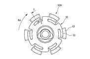
図17〜図22は第2実施形態の端子金具の接続構造を示したもので、図17は本発明に係る第2端子金具の第2実施形態の斜視図、図18は図17に示した第2端子金具と図11に示した第1端子金具との突き合わせ状態の側面図、図19は図18のH矢視図、図20は図19の状態から、第2端子金具が第1端子金具に対して矢印R4方向に所定角度だけ相対回転して、第1端子金具の接点用突部が第2端子金具の接触面上に乗り上げた状態の説明図である。また、図21は図20のI−I部分断面図、図22は図20に示した接続状態の第1端子金具と第2端子金具の斜視図である。
[Description of the terminal fitting connection structure of the second embodiment]
17 to 22 show the connection structure of the terminal fitting according to the second embodiment, FIG. 17 is a perspective view of the second embodiment of the second terminal fitting according to the present invention, and FIG. 18 is shown in FIG. FIG. 19 is a side view of the second terminal metal fitting and the first terminal metal fitting shown in FIG. 11, FIG. 19 is a view taken in the direction of the arrow H in FIG. 18, and FIG. It is explanatory drawing of the state which carried out relative rotation only by the predetermined angle to arrow R4 direction with respect to the metal fitting, and the protrusion for contact of the 1st terminal metal fitting climbed on the contact surface of the 2nd terminal metal fitting. 21 is a partial cross-sectional view taken along the line II of FIG. 20, and FIG. 22 is a perspective view of the first terminal fitting and the second terminal fitting in the connected state shown in FIG.
この第2実施形態の端子金具の接続構造では、第1実施形態の第2端子金具60の代わりに、第2端子金具60Aを使用する。 In the terminal fitting connection structure of the second embodiment, the second terminal fitting 60A is used instead of the second terminal fitting 60 of the first embodiment.
第2端子金具60Aは、第2環状部62の外周に径方向外方に突出して装備される複数の接触面63に、凹み部65を装備している。凹み部65は、接触面63上に乗り上げた第1端子金具50の接点用突部533が嵌合する窪みである。この凹み部65は、接点用突部533が嵌合することで、接点用突部533の移動を規制する。
The second terminal fitting 60 </ b> A is provided with
第2実施形態の第2端子金具60Aは、それぞれの接触面63に凹み部65を装備した点以外の構成は、第1実施形態の第2端子金具60と共通である。第1実施形態の第2端子金具60と共通の構成については、同番号を付して説明を省略する。
The configuration of the second terminal fitting 60A of the second embodiment is the same as that of the second terminal fitting 60 of the first embodiment, except that each
この第2実施形態の端子金具の接続構造の場合、接触面63上に乗り上げた接点用突部533は、図21に示すように、接触面63に備えられた凹み部65に嵌合し、凹み部65が接点用突部533の移動を規制する。
In the case of the terminal fitting connection structure of the second embodiment, the
そのため、各端子金具50,60Aに接続された電線71,72等から伝達する外部振動によって接点用突部533が接触面63上を摺動することを抑止することができる。その結果、接点用突部533が接触面63上を摺動することに起因して発生する摩耗や接触圧の低下といった問題の発生を抑止することができる。
Therefore, it is possible to prevent the
[第3実施形態の端子金具の接続構造の説明]
図23〜図26は第3実施形態の端子金具の接続構造を示したもので、図23は本発明に係る第2端子金具の第3実施形態の斜視図、図24は図23に示した第2端子金具と図11に示した第1端子金具との突き合わせ状態の側面図、図25は第3実施形態の第2端子金具と第1端子金具との相対回転時の接続状態の遷移の説明図で、図25(a)は端子金具相互を突き合わせた初期状態における接続状態の説明図、図25(b)は図25(a)から所定の相対回転によって移行する第1段階の接続状態の説明図、図25(c)は図25(b)から所定の相対回転によって移行する第2段階の接続状態の説明図、図25(d)は図25(c)から所定の相対回転によって移行する接続完了状態の説明図である。また、図26は図25に示した各接点用突部と各接触面との接続状態の三つの態様の説明図である。
[Description of the connection structure of the terminal fitting of the third embodiment]
23 to 26 show the connection structure of the terminal fitting of the third embodiment, FIG. 23 is a perspective view of the third embodiment of the second terminal fitting according to the present invention, and FIG. 24 is shown in FIG. FIG. 25 is a side view of a state in which the second terminal fitting and the first terminal fitting shown in FIG. 11 are in contact with each other. FIG. 25 is a diagram showing the transition of the connection state during relative rotation between the second terminal fitting and the first terminal fitting according to the third embodiment. FIG. 25A is an explanatory diagram of the connection state in the initial state in which the terminal fittings are brought into contact with each other, and FIG. 25B is the first stage connection state that shifts from FIG. 25A by a predetermined relative rotation. FIG. 25 (c) is an explanatory diagram of a second stage connection state transitioning from FIG. 25 (b) by a predetermined relative rotation, and FIG. 25 (d) is a predetermined relative rotation from FIG. 25 (c). It is explanatory drawing of the connection completion state which transfers. FIG. 26 is an explanatory diagram of three modes of the connection state between each contact projection and each contact surface shown in FIG.
この第3実施形態の端子金具の接続構造では、第1実施形態の第2端子金具60の代わりに、第2端子金具60Bを使用する。 In the connection structure of the terminal fitting of the third embodiment, the second terminal fitting 60B is used instead of the second terminal fitting 60 of the first embodiment.
第2端子金具60Bは、第2環状部62の外周に径方向外方に突出して装備される複数の接触面63の一縁に、傾斜面66を設けている。この傾斜面66は、接点逃がし部64に没入している接点用突部533を接触面63上に誘導する案内面である。本実施形態の傾斜面66は、接触面63の接点逃がし部64に臨む一側縁に設けられている。
The second terminal fitting 60 </ b> B is provided with an
更に、この第3実施形態の第2端子金具60Bは、第1端子金具50に装備されている複数の接点用突部533の一部は、他の接点用突部533とはタイミングをずらして第2端子金具60の接触面63に乗り上げるように、接触面63の配置が設定されている。
Further, in the second terminal fitting 60B of the third embodiment, a part of the plurality of
具体的には、例えば、第1端子金具50の中心軸に対して対称位置の接点用突部533同士は同時に第2端子金具60Bの接触面63に乗り上げるが、それ以外の接点用突部533は、タイミングをずらして後から接触面63に乗り上げるように、各接触面63の配置が調整されている。
Specifically, for example, the
この第3実施形態の第2端子金具60Bにおいて、接触面63の一縁に傾斜面66を装備した点、及び、第1端子金具50に装備されている複数の接点用突部533の全てが同一のタイミングで接触面63に乗り上げないように接触面63の配置が設定されている点、の2点以外の構成は、第1実施形態の第2端子金具60と共通である。第1実施形態の第2端子金具60と共通の構成については、同番号を付して説明を省略する。
In the second terminal fitting 60B of the third embodiment, the point that the
この第3実施形態の端子金具の接続構造の場合、第2端子金具60Bの接点逃がし部64に没入していた第1端子金具50の接点用突部533が、第1端子金具50と第2端子金具60Bの相対回転によって第2端子金具60Bの接触面63上に乗り上げる際には、接点用突部533が接触面63に連なる傾斜面66上を移動することで、接点用突部533が衝撃的に接触面63の縁に衝突することが無くなる。しかも、接点用突部533が接触面63上に乗り上げる際に発生する接触用ばね片53の撓み変形量も、徐々に変化することになる。
In the connection structure of the terminal fitting of the third embodiment, the
そのため、第1端子金具50の接点用突部533を第2端子金具60Bの接触面63上に乗り上げさせるための回転操作力を緩和することができ、また回転操作時の操作性を向上させることができる。
Therefore, it is possible to reduce the rotational operation force for causing the
また、この第3実施形態の端子金具の接続構造の場合、第1端子金具50の全ての接点用突部533が第2端子金具60Bの各接点逃がし部64に没入している未接続状態から、端子金具の相対回転によって、第1端子金具50の全ての接点用突部533が第2端子金具60Bの各接触面63上に乗り上げた接続完了状態を得ようとすると、図25(a)〜(d)に示すように、接点用突部533の接触面63への乗り上げが、段階的に進む。
Moreover, in the connection structure of the terminal metal fitting of this 3rd Embodiment, it is from the unconnected state where all the
図25(a)は、端子金具相互を突き合わせた初期状態で、全ての接点用突部533が図26(a)に示すように傾斜面66及び接触面63から離間していて、未接続状態にある。
FIG. 25A shows an initial state in which the terminal fittings are brought into contact with each other. As shown in FIG. 26A, all the
図25(b)は、図25(a)から端子金具の相対回転が進んだ状態である。この状態では、一部の接点用突部533は図26(b)に示すように傾斜面66に乗り上げるが、接触面63には未到達の状態になる。また、図26(a)に示した接続態様のものが混在している。
FIG. 25 (b) shows a state in which the relative rotation of the terminal fitting has advanced from FIG. 25 (a). In this state, some of the
図25(c)は、図25(b)から更に端子金具の相対回転が進んだ状態である。この状態では、一部の接点用突部533が、図26(c)に示すように接触面63に乗り上げて導通接続状態になるが、図26(b)に示す接続態様のもの、図26(a)に示す接続態様のものが混在している状態である。
FIG. 25 (c) shows a state in which the relative rotation of the terminal fitting has further advanced from FIG. 25 (b). In this state, some of the
図25(d)は、図25(c)から更に端子金具の相対回転が進んで、相対回転が完了した状態である。この状態では、全ての接点用突部533が、図26(c)に示すように接触面63に乗り上げて導通接続状態になる。
FIG. 25D shows a state in which the relative rotation of the terminal fitting has further advanced from FIG. 25C, and the relative rotation has been completed. In this state, all the
即ち、第3実施形態の端子金具の接続構造では、図25及び図26に示したように、第1端子金具50の接点用突部533が第2端子金具60Bの接触面63上に乗り上げる動作は、タイミングをずらして、複数の段階で進む。
That is, in the terminal fitting connection structure of the third embodiment, as shown in FIGS. 25 and 26, the
そのため、第1端子金具50に装備されている複数の接点用突部533の全てが同時に第2端子金具60Bの対応する接触面63に乗り上げる場合と比較して、同時に接触面63に乗り上げる接点用突部533の数量が少なくなる分、両端子金具間に作用させる回転操作力を低減させて、操作性を向上させることができる。
Therefore, compared to the case where all of the plurality of
[第4実施形態の端子金具の接続構造の説明]
図27及び図28は第4実施形態の端子金具の接続構造を示したもので、図27は本発明に係る第2端子金具の第4実施形態の斜視図、図28は図27に示した第2端子金具と図11に示した第1端子金具との突き合わせ状態の斜視図である。
[Description of Terminal Fitting Connection Structure of Fourth Embodiment]
27 and 28 show the connection structure of the terminal fitting of the fourth embodiment, FIG. 27 is a perspective view of the fourth embodiment of the second terminal fitting according to the present invention, and FIG. 28 is shown in FIG. FIG. 12 is a perspective view of a state in which the second terminal fitting and the first terminal fitting shown in FIG.
この第4実施形態の端子金具の接続構造では、第1実施形態の第2端子金具60の代わりに、第2端子金具60Cを使用する。 In the connection structure of the terminal fitting of the fourth embodiment, the second terminal fitting 60C is used instead of the second terminal fitting 60 of the first embodiment.
この第2端子金具60Cは、第3実施形態の第2端子金具60Bにおける接触面63に、凹み部65を追加したものである。凹み部65は、第2実施形態の第2端子金具60Aにおいて接触面63に装備されたものと同一である。即ち、凹み部65は、接触面63上に乗り上げた接点用突部533が嵌合することで、接点用突部533の移動を規制する。
The second terminal fitting 60C is obtained by adding a
第4実施形態における第2端子金具60Cは、接触面63に凹み部65を装備した点以外は、第3実施形態の第2端子金具60Bと共通の構成であり、第3実施形態と共通の構成については、同番号を付して説明を省略する。
The second terminal fitting 60C in the fourth embodiment has the same configuration as the second terminal fitting 60B of the third embodiment except that the
この第4実施形態の端子金具の接続構造の場合は、第3実施形態の端子金具の接続構造における作用効果に加えて、次の作用効果を得ることができる。
即ち、接触面63上に乗り上げた接点用突部533は、図28に示すように、接触面63に備えられた凹み部65に嵌合し、凹み部65が接点用突部533の移動を規制する。
In the case of the terminal fitting connection structure of the fourth embodiment, in addition to the actions and effects of the terminal fitting connection structure of the third embodiment, the following actions and effects can be obtained.
That is, as shown in FIG. 28, the
そのため、各端子金具50,60Cに接続された電線71,72等から伝達する外部振動によって接点用突部533が接触面63上を摺動することを抑止することができる。その結果、接点用突部533が接触面63上を摺動することに起因して発生する摩耗や接触圧の低下といった問題の発生を抑止することができる。
Therefore, it is possible to prevent the
なお、本発明は、上述した実施形態に限定されるものではなく、適宜、変形、改良、等が可能である。その他、上述した実施形態における各構成要素の材質、形状、寸法、数、配置箇所、等は本発明を達成できるものであれば任意であり、限定されない。 In addition, this invention is not limited to embodiment mentioned above, A deformation | transformation, improvement, etc. are possible suitably. In addition, the material, shape, dimensions, number, arrangement location, and the like of each component in the above-described embodiment are arbitrary and are not limited as long as the present invention can be achieved.
例えば、第1端子金具に装備されている全ての接点用突部が同一タイミングで第2端子金具の各接触面に乗り上げることを回避するために、上記実施形態では、第2端子金具における接触面63の配置を工夫する旨を示したが、第1端子金具における接点用突部の配置を工夫することで、乗り上げのタイミングをずらすようにしても良い。 For example, in order to avoid that all the contact protrusions equipped in the first terminal fitting ride on each contact face of the second terminal fitting at the same timing, in the above embodiment, the contact surface in the second terminal fitting is used. Although it has been shown that the arrangement of 63 is devised, the timing of the ride may be shifted by devising the arrangement of the contact protrusions in the first terminal fitting.
また、上記実施形態は、第1ハウジング本体21に連結用ピン214が設けられ、第2ハウジング本体31に軸方向溝315a、周方向溝315b及びロック用ばね片316が設けられた構成であるが、第2ハウジング本体31に連結用ピン214が設けられ、第1ハウジング本体21に軸方向溝315a、周方向溝315b及びロック用ばね片316が設けられた構成であってもよい。この場合、第2ハウジング本体31に設けられる連結用ピン214は、径方向内方に向けて突出するように設けられる。
In the above embodiment, the
また、上記実施形態は、連結用ピン214及びロック用ばね片316が各ハウジング本体21,31に複数設けられた構成であるが、連結用ピン214及びロック用ばね片316は、各ハウジング本体21,31に1つずつ設けられてもよい。
In the above embodiment, a plurality of connecting
また、ロック部316は、上記実施形態のようにばね片316aと係止突部316bとで構成されなくてもよく、肉抜き部が省略されてばね片316aが省略された、周方向溝315b内に張り出した係止突部316bだけの構成であってもよい。この場合、連結用ピン214は、係止突部316bにより狭められた周方向溝315b内の部分を圧接状態で通過することができる。
Further, the
ここで、上述した本発明に係る端子金具の接続構造及び回転嵌合式コネクタの実施形態の特徴をそれぞれ以下[1]〜[6]に簡潔に纏めて列記する。 Here, the features of the embodiment of the terminal fitting connection structure and the rotation fitting type connector according to the present invention described above are briefly summarized and listed in the following [1] to [6], respectively.
[1] 第1端子金具(50)に装備されている接触用ばね片(53)を、第2端子金具(60)に装備されている接触面(63)に押圧接触させることで、前記第1端子金具(50)と前記第2端子金具(60)とを導通接続状態にする端子金具の接続構造であって、
前記第1端子金具(50)は、該第1端子金具(50)の中心軸(M1)上に延在すると共に基端には前記第1端子金具(50)の中心軸(M1)と略同軸に電線(71)が接続される第1端子本体(51)と、該第1端子本体(51)の先端に前記第1端子金具(50)の中心軸(M1)と同心の環状に形成された第1環状部(52)と、該第1環状部(52)の外周上で前記第1環状部(52)の周方向に一定の間隔で並ぶ複数箇所に装備される複数の前記接触用ばね片(53)と、を備えると共に、前記接触用ばね片(53)は、前記第1環状部(52)の外周から前記第1環状部(52)の径方向外方に向かって延出したバネ支持部(531)と、該バネ支持部(531)から前記第1環状部(52)の外周に沿って延出して先端側が前記第1端子金具(50)の前記中心軸(M1)方向に変位可能な弾性片(532)と、前記第1環状部(52)の先端よりも相手端子側に突出した状態に前記弾性片(532)に突出形成された接点用突部(533)と、を備え、
前記第2端子金具(60)は、該第2端子金具(60)の中心軸(M2)上に延在すると共に基端には前記第2端子金具(60)の前記中心軸(M2)と略同軸に電線(72)が接続される第2端子本体(61)と、前記第1端子金具(50)の前記第1環状部(52)と同一の環状で前記第2端子金具(60)の前記中心軸(M2)と同心に前記第2端子本体(61)の先端に設けられた第2環状部(62)と、前記第1端子金具(50)における複数の前記接点用突部(533)と同じ間隔で前記第2環状部(62)の外周に該第2環状部(62)の径方向外方に向かって突設された複数の前記接触面(63)と、隣接する前記接触面(63)間に位置して前記接点用突部(533)が没入可能な複数の接点逃がし部(64)と、を備えた、
ことを特徴とする端子金具の接続構造。
[1] The contact spring piece (53) provided on the first terminal fitting (50) is pressed and brought into contact with the contact surface (63) provided on the second terminal fitting (60). A connection structure of a terminal metal fitting for connecting a one terminal metal fitting (50) and the second terminal metal fitting (60) in a conductive connection state,
The first terminal fitting (50) extends on the central axis (M1) of the first terminal fitting (50) and is substantially the same as the central axis (M1) of the first terminal fitting (50) at the base end. A first terminal body (51) to which an electric wire (71) is connected coaxially, and a ring concentric with the central axis (M1) of the first terminal fitting (50) are formed at the tip of the first terminal body (51). First annular portion (52) and a plurality of contacts provided at a plurality of locations arranged at regular intervals in the circumferential direction of the first annular portion (52) on the outer periphery of the first annular portion (52) And the contact spring piece (53) extends from the outer periphery of the first annular portion (52) toward the radially outer side of the first annular portion (52). A spring support portion (531) that has been taken out, and a tip end side extending from the spring support portion (531) along the outer periphery of the first annular portion (52) The elastic piece (532) displaceable in the direction of the central axis (M1) of the first terminal fitting (50), and the elastic piece in a state of protruding toward the mating terminal side from the tip of the first annular portion (52). A protrusion for contact (533) formed to protrude from (532),
The second terminal fitting (60) extends on the central axis (M2) of the second terminal fitting (60), and at the base end thereof, the central axis (M2) of the second terminal fitting (60). The second terminal fitting (60) having the same annular shape as the first annular portion (52) of the first terminal fitting (50) and the second terminal main body (61) to which the electric wire (72) is connected substantially coaxially. A second annular portion (62) provided at the tip of the second terminal body (61) concentrically with the central axis (M2), and a plurality of the contact protrusions ( 533) and a plurality of the contact surfaces (63) adjacent to the outer periphery of the second annular portion (62) projecting radially outward of the second annular portion (62) at the same interval as that of the second annular portion (62). A plurality of contact relief portions (64) that are located between the contact surfaces (63) and into which the contact protrusions (533) can be immersed; ,
This is a terminal metal connection structure.
[2] 前記第2端子金具(60)の複数の前記接触面(63)には、該接触面(63)上に乗り上げた前記接点用突部(533)が嵌合する凹み部(65)が備えられたことを特徴とする上記[1]に記載の端子金具の接続構造。 [2] The plurality of contact surfaces (63) of the second terminal fitting (60) are recessed portions (65) into which the contact protrusions (533) riding on the contact surfaces (63) are fitted. The terminal fitting connection structure according to [1] above, characterized in that is provided.
[3] 前記第2端子金具(60)の複数の前記接触面(63)の前記接点逃がし部(64)に臨む一側縁には、前記接点逃がし部(64)に没入している前記接点用突部(533)を前記接触面(63)上に誘導する傾斜面(66)が設けられたことを特徴とする上記[1]又は[2]に記載の端子金具の接続構造。 [3] The contact that is immersed in the contact relief portion (64) at one side edge facing the contact relief portion (64) of the plurality of contact surfaces (63) of the second terminal fitting (60). The terminal fitting connection structure according to the above [1] or [2], wherein an inclined surface (66) for guiding the projecting protrusion (533) onto the contact surface (63) is provided.
[4] 前記第1端子金具(50)に装備されている複数の前記接点用突部(533)の一部は、他の前記接点用突部(533)とはタイミングをずらして前記第2端子金具(60)の接触面(63)に乗り上げるように、前記接点用突部(533)及び前記接触面(63)の配置が設定されていることを特徴とする上記[1]〜[3]の何れか一つに記載の端子金具の接続構造。 [4] A part of the plurality of contact protrusions (533) provided on the first terminal fitting (50) is shifted in timing from the other contact protrusions (533). The above [1] to [3], wherein the contact protrusion (533) and the contact surface (63) are arranged so as to ride on the contact surface (63) of the terminal fitting (60). ] The connection structure of the terminal metal fitting as described in any one of.
[5] 上記[1]〜[4]の何れか一つに記載の端子金具の接続構造を利用して端子金具相互を導通接続状態にする回転式コネクタ(10)であって、
中心軸(C1)上に前記第1端子金具(50)を固定支持すると共に固定支持した前記第1端子金具(50)の先端部が前端に露出し、前記中心軸(C1)と同心の円形断面である第1ハウジング本体(21)と、該第1ハウジング本体(21)に径方向に沿って突設された連結用ピン(214)と、を備えた第1コネクタハウジング(20)と、
中心軸(C1)上に前記第2端子金具(60)を固定支持すると共に固定支持した前記第2端子金具(60)の先端部が前端に露出し、前記中心軸(C1)と同心の円形断面であり前記第1ハウジング本体(21)が嵌合する第2ハウジング本体(31)と、前記第2ハウジング本体(31)の前記第1コネクタハウジング(20)側の端部から前記第2ハウジング本体(31)の中心軸方向に沿って延在するように切欠形成されて前記第2ハウジング本体(31)に前記第1ハウジング本体(21)を前記第2ハウジング本体(31)の中心軸方向に沿って嵌合させたときに前記連結用ピン(214)が進入する軸方向溝(315a)と、該軸方向溝(315a)の終端から前記第2ハウジング本体(31)の周方向の一側に前記周方向に沿って所定の長さに延設されて前記第1ハウジング本体(21)と前記第2ハウジング本体(31)とを相対回転させたときに前記連結用ピン(214)が移動する周方向溝(315b)と、前記連結用ピン(214)が前記周方向溝(315b)の終端に到達したときに前記周方向溝(315b)の始端側から前記連結用ピン(214)に接触して前記連結用ピン(214)の戻り方向への移動を規制することでコネクタハウジング相互の結合状態をロックするロック部(316)と、を備えた第2コネクタハウジング(30)と、
を備えたことを特徴とする回転式コネクタ(10)。
[5] A rotary connector (10) that uses the terminal fitting connection structure according to any one of [1] to [4] to bring the terminal fittings into a conductive connection state.
The first terminal fitting (50) is fixedly supported on the central axis (C1), and the front end of the first terminal fitting (50) fixed and supported is exposed at the front end, and is concentric with the central axis (C1). A first connector housing (20) comprising a first housing body (21) having a cross section, and a connecting pin (214) projecting from the first housing body (21) along the radial direction;
The second terminal fitting (60) is fixedly supported on the central axis (C1), and the tip of the second terminal fitting (60) fixedly supported is exposed at the front end, and is concentric with the central axis (C1). A second housing body (31) having a cross-section and into which the first housing body (21) is fitted, and the second housing from the end of the second housing body (31) on the first connector housing (20) side. A notch is formed so as to extend along the central axis direction of the main body (31), and the first housing main body (21) is inserted into the second housing main body (31) in the central axial direction of the second housing main body (31). And the axial groove (315a) into which the connecting pin (214) enters when fitted together along the circumferential direction of the second housing body (31) from the end of the axial groove (315a). In the circumferential direction to the side Thus, a circumferential groove that extends to a predetermined length and moves the connecting pin (214) when the first housing body (21) and the second housing body (31) are relatively rotated. 315b) and when the connecting pin (214) reaches the end of the circumferential groove (315b), the connecting pin (214) comes into contact with the connecting pin (214) from the start end side of the circumferential groove (315b). A second connector housing (30) comprising: a lock portion (316) for locking the connection state between the connector housings by restricting movement of the pins (214) in the return direction;
A rotary connector (10) comprising:
[6] 上記[1]〜[4]の何れか一つに記載の端子金具の接続構造を利用して端子金具相互を導通接続状態にする回転式コネクタ(10)であって、
中心軸(C1)上に前記第1端子金具(50)を固定支持すると共に固定支持した前記第1端子金具(50)の先端部が前端に露出する第1ハウジング本体(21)と、該第1ハウジング本体(21)の外周に鍔状に形成されると共に外周が前記第1ハウジング本体(21)の前記中心軸(C1)と同心の円形となる胴部(212)と、該胴部(212)の外周から径方向外方に向けて突設された連結用ピン(214)と、を備えた第1コネクタハウジング(20)と、
中心軸(C2)上に前記第2端子金具(60)を固定支持すると共に固定支持した前記第2端子金具(60)の先端部が前端に露出する第2ハウジング本体(31)と、該第2ハウジング本体(31)の前記中心軸(C2)と同心の円筒状に前記第2ハウジング本体(31)の前端部に突設されて前記第1コネクタハウジング(20)の前記胴部(212)が嵌合する円筒部(312)と、該円筒部(312)の開口端から該円筒部(312)の中心軸(O3)方向に沿って延在するように切欠形成されて前記円筒部(312)に前記胴部(212)を前記円筒部(312)の中心軸(O3)方向に沿って嵌合させたときに前記連結用ピン(214)が進入する軸方向溝(315a)と、該軸方向溝(315a)の終端から前記円筒部(312)の周方向の一側に前記周方向に沿って所定の長さに延設されて前記円筒部(312)と前記胴部(212)とを相対回転させたときに前記連結用ピン(214)が移動する周方向溝(315b)と、前記連結用ピン(214)が前記周方向溝(315b)の終端に到達したときに前記周方向溝(315b)の始端側から前記連結用ピン(214)に弾性接触して前記連結用ピン(214)の戻り方向への移動を規制することでコネクタハウジング相互の結合状態をロックするロック用ばね片(316)と、を備えた第2コネクタハウジング(30)と、
を備えたことを特徴とする回転式コネクタ(10)。
[6] A rotary connector (10) that uses the terminal fitting connection structure according to any one of [1] to [4] to bring the terminal fittings into a conductive connection state.
A first housing body (21) for fixing and supporting the first terminal fitting (50) on a central axis (C1) and exposing a front end portion of the first terminal fitting (50) fixedly supported; A body part (212) which is formed in a bowl shape on the outer periphery of one housing body (21) and whose outer periphery is concentric with the central axis (C1) of the first housing body (21); 212) a first connector housing (20) comprising a connecting pin (214) projecting radially outward from the outer periphery of
A second housing body (31) for fixing and supporting the second terminal metal fitting (60) on a central axis (C2) and exposing a front end portion of the second terminal metal fitting (60) fixedly supported; Two cylindrical body concentric with the central axis (C2) of the housing body (31) is projected from the front end of the second housing body (31), and the body (212) of the first connector housing (20). Are fitted into the cylindrical portion (312), and the cylindrical portion (312) is cut out so as to extend from the opening end of the cylindrical portion (312) along the central axis (O3) direction of the cylindrical portion (312). 312) an axial groove (315a) into which the connecting pin (214) enters when the body portion (212) is fitted along the central axis (O3) direction of the cylindrical portion (312), From the terminal end of the axial groove (315a), the cylindrical portion (31 ) Is extended to a predetermined length along the circumferential direction on one side in the circumferential direction, and the connecting pin (214) is rotated when the cylindrical portion (312) and the body portion (212) are relatively rotated. ) To move the circumferential groove (315b) and the connecting pin (214) from the start side of the circumferential groove (315b) when the connecting pin (214) reaches the end of the circumferential groove (315b). 214) a second connector housing comprising a locking spring piece (316) that locks the coupling state of the connector housings by elastically contacting the connecting pin (214) and restricting movement of the connecting pin (214) in the return direction. (30),
A rotary connector (10) comprising:
10 回転式コネクタ
20 第1コネクタハウジング
21 第1ハウジング本体
30 第2コネクタハウジング
31 第2ハウジング本体
50 第1端子金具
51 第1端子本体
52 第1環状部
53 接触用ばね片
60 第2端子金具
61 第2端子本体
62 第2環状部
63 接触面
64 接点逃がし部
65 凹み部
66 傾斜面
71,72 電線
212 胴部
214 連結用ピン
312 円筒部
315a 軸方向溝
315b 周方向溝
316 ロック用ばね片
531 バネ支持部
532 弾性片
533 接点用突部
C1,C2,M1,M2,O3 中心軸
DESCRIPTION OF
Claims (5)
前記第1端子金具は、該第1端子金具の中心軸上に延在すると共に基端には前記第1端子金具の中心軸と略同軸に電線が接続される第1端子本体と、該第1端子本体の先端に前記第1端子金具の中心軸と同心の環状に形成された第1環状部と、該第1環状部の外周上で前記第1環状部の周方向に一定の間隔で並ぶ複数箇所に装備される複数の前記接触用ばね片と、を備えると共に、前記接触用ばね片は、前記第1環状部の外周から前記第1環状部の径方向外方に向かって延出したバネ支持部と、該バネ支持部から前記第1環状部の外周に沿って延出して先端側が前記第1端子金具の前記中心軸方向に変位可能な弾性片と、前記第1環状部の先端よりも相手端子側に突出した状態に前記弾性片に突出形成された接点用突部と、を備え、
前記第2端子金具は、該第2端子金具の中心軸上に延在すると共に基端には前記第2端子金具の前記中心軸と略同軸に電線が接続される第2端子本体と、前記第1端子金具の前記第1環状部と同一の環状で前記第2端子金具の前記中心軸と同心に前記第2端子本体の先端に設けられた第2環状部と、前記第1端子金具における複数の前記接点用突部と同じ間隔で前記第2環状部の外周に該第2環状部の径方向外方に向かって突設された複数の前記接触面と、隣接する前記接触面間に位置して前記接点用突部が没入可能な複数の接点逃がし部と、を備えた、
ことを特徴とする端子金具の接続構造。 The contact spring piece provided on the first terminal fitting is pressed and brought into contact with the contact surface provided on the second terminal fitting, thereby bringing the first terminal fitting and the second terminal fitting into a conductive connection state. The terminal fitting connection structure
The first terminal fitting extends on the central axis of the first terminal fitting, and has a first terminal main body having a proximal end connected to an electric wire substantially coaxially with the central axis of the first terminal fitting, A first annular portion formed annularly concentrically with the central axis of the first terminal fitting at a tip of one terminal main body, and at a constant interval in a circumferential direction of the first annular portion on an outer periphery of the first annular portion; A plurality of the contact spring pieces provided at a plurality of positions, and the contact spring pieces extend from the outer periphery of the first annular portion toward the radially outer side of the first annular portion. A spring support portion, an elastic piece extending from the spring support portion along the outer periphery of the first annular portion, and having a distal end side that is displaceable in the central axis direction of the first terminal fitting, and the first annular portion A protrusion for contact formed to protrude from the elastic piece in a state protruding to the counterpart terminal side from the tip,
The second terminal fitting extends on a central axis of the second terminal fitting, and a second terminal main body having a proximal end connected to an electric wire substantially coaxially with the central axis of the second terminal fitting; A second annular portion provided at the tip of the second terminal body in the same annular shape as the first annular portion of the first terminal fitting and concentrically with the central axis of the second terminal fitting; and in the first terminal fitting A plurality of contact surfaces projecting radially outward of the second annular portion on the outer periphery of the second annular portion at the same interval as the plurality of contact projections, and between the adjacent contact surfaces A plurality of contact relief portions that are positioned and into which the protrusions for contact can be immersed,
This is a terminal metal connection structure.
中心軸上に前記第1端子金具を固定支持すると共に固定支持した前記第1端子金具の先端部が前端に露出し、前記中心軸と同心の円形断面である第1ハウジング本体と、該第1ハウジング本体に径方向に沿って突設された連結用ピンと、を備えた第1コネクタハウジングと、
中心軸上に前記第2端子金具を固定支持すると共に固定支持した前記第2端子金具の先端部が前端に露出し、前記中心軸と同心の円形断面であり前記第1ハウジング本体が嵌合する第2ハウジング本体と、前記第2ハウジング本体の前記第1コネクタハウジング側の端部から前記第2ハウジング本体の中心軸方向に沿って延在するように切欠形成されて前記第2ハウジング本体に前記第1ハウジング本体を前記第2ハウジング本体の中心軸方向に沿って嵌合させたときに前記連結用ピンが進入する軸方向溝と、該軸方向溝の終端から前記第2ハウジング本体の周方向の一側に前記周方向に沿って所定の長さに延設されて前記第1ハウジング本体と前記第2ハウジング本体とを相対回転させたときに前記連結用ピンが移動する周方向溝と、前記連結用ピンが前記周方向溝の終端に到達したときに前記周方向溝の始端側から前記連結用ピンに接触して前記連結用ピンの戻り方向への移動を規制することでコネクタハウジング相互の結合状態をロックするロック部と、を備えた第2コネクタハウジングと、
を備えたことを特徴とする回転式コネクタ。 It is a rotary connector which makes a terminal metal fitting connection state using the connection structure of a terminal metal fitting as described in any one of Claims 1-4,
A first housing main body having a circular cross section concentric with the central axis, the front end of the first terminal metal fitting fixedly supported on the central axis and exposed at the front end. A first connector housing comprising a connecting pin projecting radially from the housing body;
The second terminal fitting is fixedly supported on the central axis and the tip of the second terminal fitting fixedly supported is exposed at the front end, and has a circular cross section concentric with the central axis and the first housing body is fitted. A second housing body, and a notch formed so as to extend from the end of the second housing body on the first connector housing side along the central axis direction of the second housing body; An axial groove into which the connecting pin enters when the first housing body is fitted along the central axis direction of the second housing body, and a circumferential direction of the second housing body from the end of the axial groove A circumferential groove that extends to a predetermined length along the circumferential direction on one side of the first housing main body and the second housing main body and moves the connecting pin when the relative rotation is performed. Above When the connecting pin reaches the end of the circumferential groove, the connecting pin is brought into contact with the connecting pin from the start end side of the circumferential groove to restrict the movement of the connecting pin in the return direction. A second connector housing comprising a lock portion for locking the coupled state;
A rotary connector characterized by comprising:
Priority Applications (4)
| Application Number | Priority Date | Filing Date | Title |
|---|---|---|---|
| JP2013139097A JP6031006B2 (en) | 2013-07-02 | 2013-07-02 | Terminal fitting connection structure and rotation fitting type connector |
| PCT/JP2014/067675 WO2015002240A1 (en) | 2013-07-02 | 2014-07-02 | Terminal fitting connection structure and rotary fitting-type connector |
| DE112014003142.9T DE112014003142B4 (en) | 2013-07-02 | 2014-07-02 | Connection connection and rotary connector with such |
| US14/960,850 US9450323B2 (en) | 2013-07-02 | 2015-12-07 | Terminal fitting connection structure and rotary fitting-type connector |
Applications Claiming Priority (1)
| Application Number | Priority Date | Filing Date | Title |
|---|---|---|---|
| JP2013139097A JP6031006B2 (en) | 2013-07-02 | 2013-07-02 | Terminal fitting connection structure and rotation fitting type connector |
Publications (2)
| Publication Number | Publication Date |
|---|---|
| JP2015011961A JP2015011961A (en) | 2015-01-19 |
| JP6031006B2 true JP6031006B2 (en) | 2016-11-24 |
Family
ID=52143812
Family Applications (1)
| Application Number | Title | Priority Date | Filing Date |
|---|---|---|---|
| JP2013139097A Active JP6031006B2 (en) | 2013-07-02 | 2013-07-02 | Terminal fitting connection structure and rotation fitting type connector |
Country Status (4)
| Country | Link |
|---|---|
| US (1) | US9450323B2 (en) |
| JP (1) | JP6031006B2 (en) |
| DE (1) | DE112014003142B4 (en) |
| WO (1) | WO2015002240A1 (en) |
Families Citing this family (13)
| Publication number | Priority date | Publication date | Assignee | Title |
|---|---|---|---|---|
| DE102015120921B4 (en) * | 2015-12-02 | 2017-10-19 | Kathrein Werke Kg | Connector and plug connector assembly |
| JP6734676B2 (en) * | 2016-03-28 | 2020-08-05 | 日本航空電子工業株式会社 | Sliding connector |
| JP6826878B2 (en) * | 2016-12-19 | 2021-02-10 | 日本航空電子工業株式会社 | Sliding connector |
| WO2018208857A1 (en) * | 2017-05-08 | 2018-11-15 | Eaton Intelligent Power Limited | Leaf spring sliding contact for electrically latched rocker arm assembly |
| JP6826948B2 (en) * | 2017-05-22 | 2021-02-10 | ヒロセ電機株式会社 | Terminal attachment / detachment device |
| US10927968B2 (en) | 2018-12-12 | 2021-02-23 | Bendix Commercial Vehicle Systems Llc | Pneumatic valve/pressure vessel plastic metal composite cover with bayonet retention feature |
| US10927973B2 (en) | 2018-12-12 | 2021-02-23 | Bendix Commercial Vehicle Systems Llc | Pneumatic valve/pressure vessel subcomponent with bayonet retention feature |
| CN114824849A (en) | 2021-01-29 | 2022-07-29 | 松下知识产权经营株式会社 | Lens mounting device and projector |
| JP7502723B2 (en) * | 2021-06-15 | 2024-06-19 | 株式会社オートネットワーク技術研究所 | Combination Terminal |
| CN114389109B (en) * | 2021-12-16 | 2024-03-12 | 安费诺科技(珠海)有限公司 | A rotatable plug fitting structure |
| CN114899658B (en) * | 2022-03-08 | 2024-07-30 | 深圳市尚文电子科技有限公司 | Connector convenient to connect in rotating mode |
| WO2025005918A1 (en) * | 2023-06-29 | 2025-01-02 | Itt Cannon Gmbh | Sensor connector with bayonet coupling |
| DE102024205361A1 (en) * | 2024-06-11 | 2025-12-11 | Volkswagen Aktiengesellschaft | Connection arrangement for connecting electrical lines for a motor vehicle and method for manufacturing a motor vehicle |
Family Cites Families (19)
| Publication number | Priority date | Publication date | Assignee | Title |
|---|---|---|---|---|
| US2066770A (en) | 1932-02-16 | 1937-01-05 | Miller Co | Electrical connecter |
| US2729800A (en) | 1953-04-23 | 1956-01-03 | Lewis Eng Co | Electric wire coupling |
| JPS546066Y2 (en) * | 1974-11-25 | 1979-03-19 | ||
| JPS5168389A (en) | 1974-12-06 | 1976-06-12 | Nippon Dev Consult | Yokinoseikei jutensochi |
| JPS57179274A (en) | 1981-04-27 | 1982-11-04 | Ryota Kamakari | Preparation of partially laminated gasket |
| JPS6328536Y2 (en) * | 1981-05-08 | 1988-08-01 | ||
| US5059143A (en) | 1988-09-08 | 1991-10-22 | Amp Incorporated | Connector contact |
| JP2842145B2 (en) | 1993-04-07 | 1998-12-24 | 住友電装株式会社 | connector |
| US5558531A (en) * | 1994-02-09 | 1996-09-24 | Yazaki Corporation | Combination terminal |
| US5529509A (en) * | 1995-05-12 | 1996-06-25 | Alcoa Fujikura Limited | Interlocking ground terminal |
| US5865638A (en) * | 1995-12-21 | 1999-02-02 | Alcoa Fujikura Ltd. | Electrical connector |
| JPH09232019A (en) | 1996-02-22 | 1997-09-05 | Unisia Jecs Corp | Connection terminal for wiring |
| US5759056A (en) * | 1996-07-24 | 1998-06-02 | Yazaki Corporation | Interlockable eyelet terminal |
| JP2000277197A (en) * | 1999-03-23 | 2000-10-06 | Harness Syst Tech Res Ltd | Terminal structure |
| US6409531B1 (en) * | 2001-02-12 | 2002-06-25 | Microhelix, Inc. | Easily mated compact connector |
| US7344421B1 (en) | 2005-06-06 | 2008-03-18 | Spencer Troy L | Quick release battery cable connector |
| US7355122B2 (en) | 2006-03-31 | 2008-04-08 | Azura Energy Systems, Inc. | Sealed eurytopic make-break connector utilizing a conductive elastomer contact |
| ATE474345T1 (en) * | 2007-11-30 | 2010-07-15 | Delphi Tech Inc | ELECTRICAL CONNECTION ELEMENT |
| JP5424050B2 (en) * | 2010-04-16 | 2014-02-26 | 住友電装株式会社 | Male terminal and vehicle side connector |
-
2013
- 2013-07-02 JP JP2013139097A patent/JP6031006B2/en active Active
-
2014
- 2014-07-02 DE DE112014003142.9T patent/DE112014003142B4/en not_active Expired - Fee Related
- 2014-07-02 WO PCT/JP2014/067675 patent/WO2015002240A1/en not_active Ceased
-
2015
- 2015-12-07 US US14/960,850 patent/US9450323B2/en active Active
Also Published As
| Publication number | Publication date |
|---|---|
| DE112014003142B4 (en) | 2022-10-06 |
| WO2015002240A1 (en) | 2015-01-08 |
| DE112014003142T5 (en) | 2016-03-31 |
| JP2015011961A (en) | 2015-01-19 |
| US20160087365A1 (en) | 2016-03-24 |
| US9450323B2 (en) | 2016-09-20 |
Similar Documents
| Publication | Publication Date | Title |
|---|---|---|
| JP6031006B2 (en) | Terminal fitting connection structure and rotation fitting type connector | |
| JP6106544B2 (en) | Rotary connector | |
| JP4803743B2 (en) | connector | |
| JP6183626B2 (en) | Coaxial connector with floating mechanism | |
| JP4867875B2 (en) | Lever type connector | |
| JP5193888B2 (en) | connector | |
| US9054452B2 (en) | Electrical connector assembled component | |
| JP6154270B2 (en) | Connector device | |
| JP2004247170A (en) | Press spring connector | |
| EP2866309B1 (en) | Connector structure | |
| JP7149542B2 (en) | connector | |
| JP6889696B2 (en) | Corrugated tube holder and wire harness | |
| CN107123886B (en) | Terminal connecting structure and electric connector | |
| JP6002626B2 (en) | connector | |
| JP2013016307A (en) | Lever-type connector | |
| JP2007179860A (en) | connector | |
| JP2009266642A (en) | Connector | |
| CN116941143A (en) | Rod type connector | |
| WO2018061981A1 (en) | Connector assembly | |
| JP2009259553A (en) | Connector | |
| JP5534504B2 (en) | Low insertion force connector | |
| JP2007059153A (en) | Connector | |
| JP4720718B2 (en) | Shield connector | |
| JP5538815B2 (en) | Low insertion force connector | |
| JP2012234635A (en) | Connector |
Legal Events
| Date | Code | Title | Description |
|---|---|---|---|
| RD02 | Notification of acceptance of power of attorney |
Free format text: JAPANESE INTERMEDIATE CODE: A7422 Effective date: 20150122 |
|
| A621 | Written request for application examination |
Free format text: JAPANESE INTERMEDIATE CODE: A621 Effective date: 20160519 |
|
| TRDD | Decision of grant or rejection written | ||
| A01 | Written decision to grant a patent or to grant a registration (utility model) |
Free format text: JAPANESE INTERMEDIATE CODE: A01 Effective date: 20160927 |
|
| A61 | First payment of annual fees (during grant procedure) |
Free format text: JAPANESE INTERMEDIATE CODE: A61 Effective date: 20161021 |
|
| R150 | Certificate of patent or registration of utility model |
Ref document number: 6031006 Country of ref document: JP Free format text: JAPANESE INTERMEDIATE CODE: R150 |
|
| R250 | Receipt of annual fees |
Free format text: JAPANESE INTERMEDIATE CODE: R250 |
|
| R250 | Receipt of annual fees |
Free format text: JAPANESE INTERMEDIATE CODE: R250 |
|
| R250 | Receipt of annual fees |
Free format text: JAPANESE INTERMEDIATE CODE: R250 |
|
| R250 | Receipt of annual fees |
Free format text: JAPANESE INTERMEDIATE CODE: R250 |
|
| S531 | Written request for registration of change of domicile |
Free format text: JAPANESE INTERMEDIATE CODE: R313531 |
|
| R350 | Written notification of registration of transfer |
Free format text: JAPANESE INTERMEDIATE CODE: R350 |
|
| R250 | Receipt of annual fees |
Free format text: JAPANESE INTERMEDIATE CODE: R250 |
|
| R250 | Receipt of annual fees |
Free format text: JAPANESE INTERMEDIATE CODE: R250 |