JP6008060B1 - Glass substrate for magnetic recording medium, magnetic recording medium, method for manufacturing glass substrate for magnetic recording medium, and glass substrate manufacturing apparatus for magnetic recording medium - Google Patents
Glass substrate for magnetic recording medium, magnetic recording medium, method for manufacturing glass substrate for magnetic recording medium, and glass substrate manufacturing apparatus for magnetic recording medium Download PDFInfo
- Publication number
- JP6008060B1 JP6008060B1 JP2016090306A JP2016090306A JP6008060B1 JP 6008060 B1 JP6008060 B1 JP 6008060B1 JP 2016090306 A JP2016090306 A JP 2016090306A JP 2016090306 A JP2016090306 A JP 2016090306A JP 6008060 B1 JP6008060 B1 JP 6008060B1
- Authority
- JP
- Japan
- Prior art keywords
- outer peripheral
- glass substrate
- inner peripheral
- peripheral end
- magnetic recording
- Prior art date
- Legal status (The legal status is an assumption and is not a legal conclusion. Google has not performed a legal analysis and makes no representation as to the accuracy of the status listed.)
- Active
Links
Images



Classifications
-
- B—PERFORMING OPERATIONS; TRANSPORTING
- B24—GRINDING; POLISHING
- B24B—MACHINES, DEVICES, OR PROCESSES FOR GRINDING OR POLISHING; DRESSING OR CONDITIONING OF ABRADING SURFACES; FEEDING OF GRINDING, POLISHING, OR LAPPING AGENTS
- B24B9/00—Machines or devices designed for grinding edges or bevels on work or for removing burrs; Accessories therefor
-
- G—PHYSICS
- G11—INFORMATION STORAGE
- G11B—INFORMATION STORAGE BASED ON RELATIVE MOVEMENT BETWEEN RECORD CARRIER AND TRANSDUCER
- G11B5/00—Recording by magnetisation or demagnetisation of a record carrier; Reproducing by magnetic means; Record carriers therefor
- G11B5/62—Record carriers characterised by the selection of the material
- G11B5/73—Base layers, i.e. all non-magnetic layers lying under a lowermost magnetic recording layer, e.g. including any non-magnetic layer in between a first magnetic recording layer and either an underlying substrate or a soft magnetic underlayer
- G11B5/739—Magnetic recording media substrates
- G11B5/73911—Inorganic substrates
- G11B5/73921—Glass or ceramic substrates
-
- C—CHEMISTRY; METALLURGY
- C03—GLASS; MINERAL OR SLAG WOOL
- C03C—CHEMICAL COMPOSITION OF GLASSES, GLAZES OR VITREOUS ENAMELS; SURFACE TREATMENT OF GLASS; SURFACE TREATMENT OF FIBRES OR FILAMENTS MADE FROM GLASS, MINERALS OR SLAGS; JOINING GLASS TO GLASS OR OTHER MATERIALS
- C03C19/00—Surface treatment of glass, not in the form of fibres or filaments, by mechanical means
-
- G—PHYSICS
- G11—INFORMATION STORAGE
- G11B—INFORMATION STORAGE BASED ON RELATIVE MOVEMENT BETWEEN RECORD CARRIER AND TRANSDUCER
- G11B5/00—Recording by magnetisation or demagnetisation of a record carrier; Reproducing by magnetic means; Record carriers therefor
- G11B5/84—Processes or apparatus specially adapted for manufacturing record carriers
Landscapes
- Chemical & Material Sciences (AREA)
- Engineering & Computer Science (AREA)
- Mechanical Engineering (AREA)
- Ceramic Engineering (AREA)
- Inorganic Chemistry (AREA)
- Chemical Kinetics & Catalysis (AREA)
- Life Sciences & Earth Sciences (AREA)
- General Chemical & Material Sciences (AREA)
- Geochemistry & Mineralogy (AREA)
- Materials Engineering (AREA)
- Organic Chemistry (AREA)
- Manufacturing Of Magnetic Record Carriers (AREA)
- Magnetic Record Carriers (AREA)
Abstract
【課題】主表面と外周面取り部との間の微細な疵を抑制した磁気記録媒体用ガラス基板を提供する。【解決手段】ドーナツ形状を有し、一対の主表面と、外周端面と、内周端面と、を有する磁気記録媒体用ガラス基板であって、前記外周端面は外周側面部と一対の外周面取り部とを有し、前記一対の外周面取り部のうち、少なくとも一方の外周面取り部の面取り幅を複数の測定点で測定した場合に、測定値の最大値と、最小値との差が10μm以下である磁気記録媒体用ガラス基板を提供する。【選択図】図2To provide a glass substrate for a magnetic recording medium in which fine wrinkles between a main surface and an outer peripheral chamfered portion are suppressed. A glass substrate for a magnetic recording medium having a donut shape and having a pair of main surfaces, an outer peripheral end surface, and an inner peripheral end surface, wherein the outer peripheral end surface is an outer peripheral side surface portion and a pair of outer peripheral chamfered portions. And when the chamfer width of at least one outer peripheral chamfered portion of the pair of outer peripheral chamfered portions is measured at a plurality of measurement points, the difference between the maximum value and the minimum value is 10 μm or less. A glass substrate for a magnetic recording medium is provided. [Selection] Figure 2
Description
本発明は、磁気記録媒体用ガラス基板、磁気記録媒体、磁気記録媒体用ガラス基板の製造方法、及び磁気記録媒体用ガラス基板製造装置に関する。 The present invention relates to a glass substrate for a magnetic recording medium, a magnetic recording medium, a method for manufacturing a glass substrate for a magnetic recording medium, and a glass substrate manufacturing apparatus for a magnetic recording medium.
磁気ディスク記録装置等に用いられる磁気記録媒体用基板としては、従来、アルミニウム合金基板が使用されてきた。しかしながら、近年、高記録密度化の要求に伴い、アルミニウム合金基板に比べて硬く、平坦性や平滑性に優れるガラス基板が主流となってきている。 Conventionally, aluminum alloy substrates have been used as substrates for magnetic recording media used in magnetic disk recording devices and the like. However, in recent years, with the demand for higher recording density, glass substrates that are harder than aluminum alloy substrates and excellent in flatness and smoothness have become mainstream.
磁気記録媒体用ガラス基板は、中央部に同心円状の開口部を有するドーナツ形状を有しており、外周端面や内周端面は、主表面と略垂直な側面部と、側面部と主表面との間に設けられた面取り部とを有している。 The glass substrate for a magnetic recording medium has a donut shape having a concentric opening at the center, and the outer peripheral end surface and the inner peripheral end surface are a side surface portion that is substantially perpendicular to the main surface, and the side surface portion and the main surface. And a chamfered portion provided between the two.
そして、磁気記録媒体用ガラス基板の外周端面に設けられる外周面取り部や、内周端面に設けられる内周面取り部の形状については従来から各種検討がなされている。 Various studies have been made on the shape of the outer peripheral chamfered portion provided on the outer peripheral end surface of the magnetic recording medium glass substrate and the inner peripheral chamfered portion provided on the inner peripheral end surface.
例えば特許文献1には、装着信頼性の高い磁気記録媒体用ガラス基板を提供することを目的として、主表面と側面との間に面取りによる面取部が形成されているとともに、主表面と面取部との間及び側面と面取部との間のうち少なくとも一方に半径0.003mm以上0.2mm未満の曲面が形成された磁気記録媒体用ガラス基板の製造方法が開示されている。 For example, in Patent Document 1, for the purpose of providing a glass substrate for a magnetic recording medium with high mounting reliability, a chamfered portion is formed between the main surface and the side surface, and the main surface and the surface. A method for manufacturing a glass substrate for a magnetic recording medium is disclosed in which a curved surface having a radius of 0.003 mm or more and less than 0.2 mm is formed between at least one of a portion between a chamfered portion and between a side surface and a chamfered portion.
磁気記録媒体用ガラス基板を製造する場合、例えばガラス素板からドーナツ形状に加工する工程や、端面に上述の面取り部を形成する面取り工程、主表面を研磨する主表面研磨工程、端面を研磨する端面研磨工程等を行い所望の形状に加工されている。 When manufacturing a glass substrate for a magnetic recording medium, for example, a step of processing from a glass base plate into a donut shape, a chamfering step of forming the above-mentioned chamfered portion on the end surface, a main surface polishing step of polishing the main surface, and polishing the end surface It is processed into a desired shape by performing an end face polishing process or the like.
そして、端面に面取り部を形成する面取り工程の後、主表面研磨工程を実施した場合に、主表面と、外周面取り部との間に微細な疵が生じ、得られる磁気記録媒体用ガラス基板に係る疵が含まれている場合があった。係る疵は微細なため従来は問題とされていなかった。 Then, when the main surface polishing step is performed after the chamfering step for forming the chamfered portion on the end surface, fine wrinkles are generated between the main surface and the outer peripheral chamfered portion, and the obtained glass substrate for magnetic recording medium In some cases, such spiders were included. Such wrinkles are fine and have not been considered a problem in the past.
しかしながら、近年は磁気記録媒体の高記録密度化が図られ、記録するデータの1ビット当たりの占有面積は小さくなっている。また、磁気記録媒体の外周端面近傍まで情報が書き込まれるようになっている。 However, in recent years, the recording density of magnetic recording media has been increased, and the occupied area per bit of data to be recorded has been reduced. Information is written to the vicinity of the outer peripheral end face of the magnetic recording medium.
このため、疵のサイズが微細であり、外周端面の近傍であっても、高記録密度化が進み、また外周端面近傍まで書き込みがなされる磁気記録媒体では、疵の密集度等によってはエラー発生の原因となる。従って、磁気記録媒体用ガラス基板において、主表面と外周面取り部との間の微細な疵を低減、抑制することが求められている。 For this reason, even if the size of the wrinkles is fine and the recording density is increased even in the vicinity of the outer peripheral end face, an error occurs depending on the density of the wrinkles in the magnetic recording medium in which writing is performed up to the vicinity of the outer peripheral end face. Cause. Therefore, in the glass substrate for magnetic recording media, it is required to reduce and suppress fine wrinkles between the main surface and the outer peripheral chamfered portion.
上記従来技術が有する問題に鑑み、本発明の一側面では主表面と外周面取り部との間の微細な疵を抑制した磁気記録媒体用ガラス基板を提供することを目的とする。 In view of the problems of the above-described conventional technology, an object of one aspect of the present invention is to provide a glass substrate for a magnetic recording medium in which fine wrinkles between a main surface and an outer peripheral chamfered portion are suppressed.
上記課題を解決するため本発明の一側面では、ドーナツ形状を有し、一対の主表面と、外周端面と、内周端面と、を有する磁気記録媒体用ガラス基板であって、前記外周端面は外周側面部と一対の外周面取り部とを有し、
前記一対の外周面取り部のうち、少なくとも一方の外周面取り部の面取り幅を複数の測定点で測定した場合に、測定値の最大値と、最小値との差が9.8μm以下である磁気記録媒体用ガラス基板を提供する。
In order to solve the above problems, in one aspect of the present invention, a glass substrate for a magnetic recording medium having a donut shape and having a pair of main surfaces, an outer peripheral end surface, and an inner peripheral end surface, the outer peripheral end surface is It has an outer peripheral side part and a pair of outer peripheral chamfered parts,
When the chamfer width of at least one outer peripheral chamfered portion of the pair of outer peripheral chamfered portions is measured at a plurality of measurement points, the difference between the maximum measured value and the minimum value is 9.8 μm or less. A glass substrate for a recording medium is provided.
本発明の磁気記録媒体用ガラス基板の一側面によれば、主表面と外周面取り部との間の微細な疵を抑制した磁気記録媒体用ガラス基板を提供することができる。 According to one aspect of the glass substrate for a magnetic recording medium of the present invention, it is possible to provide a glass substrate for a magnetic recording medium that suppresses fine wrinkles between the main surface and the outer peripheral chamfered portion.
以下、本発明を実施するための形態について図面を参照して説明するが、本発明は、下記の実施形態に制限されることはなく、本発明の範囲を逸脱することなく、下記の実施形態に種々の変形および置換を加えることができる。
(磁気記録媒体用ガラス基板)
本実施形態の磁気記録媒体用ガラス基板の一構成例について説明を行う。
DESCRIPTION OF EMBODIMENTS Hereinafter, embodiments for carrying out the present invention will be described with reference to the drawings. However, the present invention is not limited to the following embodiments, and the following embodiments are not departed from the scope of the present invention. Various modifications and substitutions can be made.
(Glass substrate for magnetic recording media)
One structural example of the glass substrate for magnetic recording media of this embodiment is demonstrated.
本実施形態の磁気記録媒体用ガラス基板は、ドーナツ形状を有し、一対の主表面と、外周端面と、内周端面と、を有する磁気記録媒体用ガラス基板であって、外周端面は外周側面部と一対の外周面取り部とを有することができる。そして、一対の外周面取り部のうち、少なくとも一方の外周面取り部の面取り幅を複数の測定点で測定した場合に、測定値の最大値と、最小値との差を10μm以下とすることができる。 The glass substrate for a magnetic recording medium of the present embodiment is a glass substrate for a magnetic recording medium having a donut shape and having a pair of main surfaces, an outer peripheral end surface, and an inner peripheral end surface, and the outer peripheral end surface is an outer peripheral side surface. And a pair of outer peripheral chamfers. And when the chamfering width of at least one outer peripheral chamfered portion of the pair of outer peripheral chamfered portions is measured at a plurality of measurement points, the difference between the maximum value and the minimum value of the measured value can be 10 μm or less. .
まず、図1を用いて本実施形態の磁気記録媒体用ガラス基板の構造について説明する。 First, the structure of the glass substrate for magnetic recording media of this embodiment will be described with reference to FIG.
図1(A)は本実施形態の磁気記録媒体用ガラス基板の斜視断面図を模式的に示している。図1(A)は磁気記録媒体用ガラス基板10の中心を通り、主表面121、122と垂直な面における断面を含む斜視断面図となっている。すなわち、図1(A)では本実施形態の磁気記録媒体用ガラス基板の半分と、断面図とをあわせて示している。
FIG. 1A schematically shows a perspective sectional view of a glass substrate for a magnetic recording medium according to the present embodiment. FIG. 1A is a perspective cross-sectional view including a cross section in a plane that passes through the center of the
また、図1(B)は、本実施形態の磁気記録媒体用ガラス基板の面取り幅を説明するために示した図であり、本実施形態の磁気記録媒体用ガラス基板の上面図を模式的に示している。なお、図中面取り幅を実際よりも大きくして示している。 FIG. 1B is a view for explaining the chamfering width of the glass substrate for magnetic recording medium of the present embodiment, and schematically shows a top view of the glass substrate for magnetic recording medium of the present embodiment. Show. In the figure, the chamfer width is shown larger than the actual width.
図1(A)、図1(B)から把握されるように、磁気記録媒体用ガラス基板10は外周が円形であり、中央部には外周と同心円となるように円形の開口部(中央開口部)11が設けられた円板形状、すなわちドーナツ形状を有している。
As can be understood from FIGS. 1A and 1B, the
そして、上下の面が主表面121、122となっている。また、磁気記録媒体用ガラス基板10は外周に位置する外周端面13と、内周に位置する内周端面14と、を有している。
The upper and lower surfaces are
外周端面13、及び内周端面14は主表面121、122側にそれぞれ面取り部を有することができる。すなわち、外周端面13、及び内周端面14は、それぞれ一対の面取り部を有することができる。具体的には外周端面13は外周面取り部131、133を、内周端面14は内周面取り部141、143をそれぞれ有することができる。
The outer
また、面取り部間には側面部を形成することができ、外周端面13は外周側面部132を、内周端面14は内周側面部142をそれぞれ有することができる。外周側面部132、及び内周側面部142はそれぞれ主表面121、122と略垂直になるように形成できる。
Further, a side surface portion can be formed between the chamfered portions, the outer
以上のように、外周端面13は外周側面部132と、外周面取り部131、133とを含み、内周端面14は内周側面部142と内周面取り部141、143とを含むことができる。
As described above, the outer
なお、本実施形態の磁気記録媒体用ガラス基板のサイズは特に限定されるものではないく、磁気記録媒体用ガラス基板の仕様にあわせて任意に選択することができる。本実施形態の磁気記録媒体用ガラス基板の直径は例えば48mm、65mm、または95mm等の磁気記録媒体用ガラス基板に要求される仕様に応じたサイズとすることができる。特に、本実施形態の磁気記録媒体用ガラス基板の直径は、近年需要が高まっている65mm以上であることが好ましい。 In addition, the size of the glass substrate for magnetic recording media of this embodiment is not particularly limited, and can be arbitrarily selected according to the specifications of the glass substrate for magnetic recording media. The diameter of the glass substrate for magnetic recording media of the present embodiment can be set to a size according to specifications required for the glass substrate for magnetic recording media, such as 48 mm, 65 mm, or 95 mm. In particular, the diameter of the glass substrate for a magnetic recording medium of the present embodiment is preferably 65 mm or more, for which demand is increasing in recent years.
既述のように、磁気記録媒体用ガラス基板の主表面を研磨する主表面研磨工程において、主表面と、端面との間、例えば主表面121と、外周面取り部131との間に微細な疵が生じる場合があった。疵のサイズが微細であり、外周端面の近傍であっても、高記録密度化が進み、また外周端面近傍まで書き込みがなされる磁気記録媒体では、疵の密集度等によってはエラー発生の原因となる。従って、磁気記録媒体用ガラス基板において、係る微細な疵の発生を抑制することが求められていた。そこでまず、本発明の発明者らは係る微細な疵が生じる原因について検討を行った。
As described above, in the main surface polishing step for polishing the main surface of the glass substrate for magnetic recording medium, fine wrinkles are formed between the main surface and the end surface, for example, between the
主表面研磨工程は通常、ドーナツ形状に形状付与されたガラス基板の端面に面取り部を形成する面取り工程の後に実施する。面取り工程では、従来は例えば外周面取り部について任意の1点で面取り幅を測定し許容範囲内にあれば合格品として、主表面研磨工程に供していた。 The main surface polishing step is usually performed after the chamfering step of forming a chamfered portion on the end surface of the glass substrate that is shaped into a donut shape. In the chamfering process, conventionally, for example, the chamfering width of the outer peripheral chamfered part is measured at an arbitrary point and if it is within the allowable range, it is used as the acceptable product for the main surface polishing process.
そして、ガラス基板の主表面の研磨は、通常、両面研磨装置を用いて実施される。具体的には、両面研磨装置にセットしたガラス基板の両主表面にそれぞれ、研磨パッドを押し当てた状態で、ガラス基板と、研磨パッドとの間に研磨スラリーを供給しながら、ガラス基板及び研磨パッドを回転させて実施できる。 And the grinding | polishing of the main surface of a glass substrate is normally implemented using a double-side polish apparatus. Specifically, in a state where the polishing pad is pressed against both main surfaces of the glass substrate set in the double-side polishing apparatus, while supplying the polishing slurry between the glass substrate and the polishing pad, the glass substrate and the polishing are supplied. This can be done by rotating the pad.
上述のように、従来は例えば外周面取り部について、面取り幅が適切になるように面取りできているかは、外周面取り部について1点で測定するのみで合格品であるかを判定しており、そのばらつきについては特に着目されていなかった。しかし、本発明者らは前記の主表面と外周面取り部との間の微細な疵と、外周面取り部の幅のばらつきに相関があることを見出した。より具体的には、本発明の発明者らは、従来は問題にされなかったような面取り部の面取り幅のわずかなばらつきが、その後の主表面研磨工程において、主表面と面取り部との間に微細な疵を生じる原因となっていることを見出した。 As described above, in the past, for example, for the outer peripheral chamfered portion, whether the chamfering width is appropriate or not is determined by only measuring the outer peripheral chamfered portion at one point. No particular attention was paid to the variation. However, the present inventors have found that there is a correlation between the fine wrinkles between the main surface and the outer peripheral chamfered portion and the variation in the width of the outer peripheral chamfered portion. More specifically, the inventors of the present invention have found that a slight variation in the chamfer width of the chamfered portion, which has not been a problem in the past, may occur between the main surface and the chamfered portion in the subsequent main surface polishing step. Has been found to cause fine wrinkles.
これは、本発明の発明者らの検討によれば、面取り部の面取り幅のばらつきが大きいと、面取り幅の大きい部分に研磨スラリーが溜まってスラリーが表面に入り込む量が不安定になり、スラリー中の大きな粒により疵を生じたり、両面研磨装置内での磁気記録媒体用ガラス基板の自転を妨げる等するためと推認される。 According to the study of the inventors of the present invention, when the variation of the chamfer width of the chamfered portion is large, the amount of the slurry entering the surface becomes unstable because the slurry is accumulated in the portion where the chamfer width is large. It is presumed to cause wrinkles due to large grains in the inside, or to prevent rotation of the glass substrate for magnetic recording medium in the double-side polishing apparatus.
そこで、本実施形態の磁気記録媒体用ガラス基板は、一対の外周面取り部のうち、少なくとも一方の外周面取り部の面取り幅を複数の測定点で測定した場合に、測定値の最大値と、最小値との差が10μm以下であることが好ましい。特に、少なくとも一方の外周面取り部の面取り幅を複数の測定点で測定した場合に、測定値の最大値と、最小値との差は8μm以下であることがより好ましく、5μm以下であることがさらに好ましい。 Therefore, the glass substrate for a magnetic recording medium of the present embodiment has a maximum value and a minimum value when the chamfer width of at least one outer peripheral chamfered portion of the pair of outer peripheral chamfered portions is measured at a plurality of measurement points. The difference from the value is preferably 10 μm or less. In particular, when the chamfer width of at least one outer peripheral chamfered portion is measured at a plurality of measurement points, the difference between the maximum value and the minimum value is more preferably 8 μm or less, and preferably 5 μm or less. Further preferred.
本発明の発明者らの検討によると、少なくとも一方の外周面取り部の面取り幅を複数の測定点で測定した場合の測定値の最大値と、最小値との差を10μm以下とすることで、主表面研磨工程後に、特に微細な疵の発生の抑制が求められる主表面と外周面取り部との間に微細な疵が発生することを抑制できる。このため、高記録密度化が進んだ磁気記録媒体に用いる磁気記録媒体用ガラス基板の歩留まりを向上させることができ、生産性を高めることができる。また、磁気記録媒体とした場合にエラーの発生率を抑制できる。 According to the study of the inventors of the present invention, the difference between the maximum value and the minimum value when measuring the chamfer width of at least one outer peripheral chamfer at a plurality of measurement points is 10 μm or less. After the main surface polishing step, it is possible to suppress the generation of fine wrinkles between the main surface and the outer peripheral chamfered portion that are particularly required to suppress the generation of fine wrinkles. For this reason, the yield of the glass substrate for magnetic recording media used for the magnetic recording medium whose recording density has been increased can be improved, and productivity can be increased. Further, when the magnetic recording medium is used, the error occurrence rate can be suppressed.
なお、既述のように磁気記録媒体用ガラス基板10は、一対の外周面取り部131、133を有することができる。
As described above, the glass substrate for
このように磁気記録媒体用ガラス基板が一対の外周面取り部を有する場合、上述のように少なくとも一方の外周面取り部について、外周面取り部の面取り幅を複数の測定点で測定した場合に、測定値の最大値と、最小値との差が上記範囲を満たすことが好ましい。すなわち、例えば一方の外周面取り部131について、外周に沿って選択した任意の複数の測定点で面取り幅を測定した場合の測定値の最大値と、最小値との差が10μm以下であることが好ましい。
As described above, when the glass substrate for magnetic recording medium has a pair of outer peripheral chamfered portions, as described above, when the chamfer width of the outer peripheral chamfered portion is measured at a plurality of measurement points, the measured value is measured. It is preferable that the difference between the maximum value and the minimum value satisfies the above range. That is, for example, for one outer
これは、一対の外周面取り部は、外周端面研削用砥石により同時に形成されており、同じ磁気記録媒体用ガラス基板に含まれる、一対の外周面取り部の面取り幅の最大値と、最小値との差は通常同程度になるためである。 This is because the pair of outer peripheral chamfered portions are formed simultaneously by the outer peripheral end surface grinding grindstone, and the maximum and minimum values of the chamfer width of the pair of outer peripheral chamfered portions included in the same glass substrate for magnetic recording medium. This is because the difference is usually similar.
特に、両方の外周面取り部131、133について、各外周面取り部において、外周に沿って選択した任意の複数の測定点で面取り幅を測定した場合の、各外周面取り部における、面取り幅の測定値の最大値と、最小値との差が上記範囲を満たすことがより好ましい。
In particular, for both outer peripheral
また、面取り工程後、さらに主表面研磨工程等の各種研磨工程等を実施しても、少なくとも一方の外周面取り部の面取り幅を複数の測定点で測定した場合の、測定値の最大値と、最小値との差は殆ど変化しない。このため、主表面研磨工程に供する外周面取り部を形成したドーナツ形状を有するガラス基板、及びさらに各種研磨工程等を施した磁気記録媒体用ガラス基板は共に、少なくとも一方の外周面取り部の面取り幅を複数の測定点で測定した際の、測定値の最大値と、最小値との差が上記範囲を満たすことが好ましい。 In addition, after the chamfering process, even when performing various polishing processes such as the main surface polishing process, the maximum value of the measured value when measuring the chamfer width of at least one outer peripheral chamfered portion at a plurality of measurement points, The difference from the minimum value hardly changes. For this reason, both the glass substrate having a donut shape on which the outer peripheral chamfered portion is provided for the main surface polishing step and the glass substrate for magnetic recording medium subjected to various polishing steps and the like have a chamfer width of at least one outer peripheral chamfered portion. It is preferable that the difference between the maximum value and the minimum value of the measurement values measured at a plurality of measurement points satisfies the above range.
ここで、外周面取り部の面取り幅とは、面取り部の水平方向の長さ、すなわち主表面と平行な方向の長さを意味しており、図1(A)、図1(B)中にLODとして示した長さとなる。なお、外周面取り部の面取り幅LODは、図1(B)中に示したように、磁気記録媒体用ガラス基板10の中心Oを通る線上で測定することになる。
Here, the chamfered width of the outer peripheral chamfered portion means the length of the chamfered portion in the horizontal direction, that is, the length in the direction parallel to the main surface, and in FIGS. 1 (A) and 1 (B) The length is shown as L OD . The chamfering width L OD of the outer peripheral chamfered portion is measured on a line passing through the center O of the magnetic recording
外周面取り部の面取り幅の測定は、上述のように磁気記録媒体用ガラス基板の外周に沿って複数の測定点、すなわち例えば2点以上で測定すればよく、具体的な測定点の数は特に限定されるものではない。ただし、面取り幅のばらつきが十分に評価できるように、生産性を損なわない範囲で測定点の数を選択することが好ましい。 The chamfer width of the outer peripheral chamfered portion may be measured at a plurality of measurement points along the outer periphery of the magnetic recording medium glass substrate as described above, that is, for example, at two or more points. It is not limited. However, it is preferable to select the number of measurement points within a range that does not impair the productivity so that the variation in chamfer width can be sufficiently evaluated.
面取り幅を測定する際の測定点の数は、例えば4点以上であることが好ましく、20点以上であることがより好ましい。 The number of measurement points when measuring the chamfer width is, for example, preferably 4 points or more, and more preferably 20 points or more.
ただし、生産性の観点から面取り幅を測定する際の測定点の数は、360点以下であることが好ましく、180点以下であることがより好ましい。 However, from the viewpoint of productivity, the number of measurement points when measuring the chamfer width is preferably 360 points or less, and more preferably 180 points or less.
なお、ここでの測定点の数とは、1つの外周面取り部の面取り幅を測定する際の測定点の数を意味している。 Note that the number of measurement points here means the number of measurement points when measuring the chamfer width of one outer peripheral chamfer.
面取り幅を測定する際の測定点間の距離は一定であることが好ましい。このため、例えば一の測定点と、磁気記録媒体用ガラス基板の中心と、上記一の測定点に隣接する測定点とで形成する角度は、360°を測定点の数で除した値となっていることが好ましい。 The distance between measurement points when measuring the chamfer width is preferably constant. For this reason, for example, the angle formed by one measurement point, the center of the glass substrate for magnetic recording media, and the measurement point adjacent to the one measurement point is a value obtained by dividing 360 ° by the number of measurement points. It is preferable.
外周面取り部の面取り幅LODの長さは特に限定されるものではなく、磁気記録媒体用ガラス基板に要求される仕様に応じて選択することができる。ただし、外周面取り部の面取り幅LODの長さが長くなりすぎると、主表面の面積が狭くなる恐れがある。このため、外周面取り部の面取り幅LODは200μm以下であることが好ましい。外周面取り部の面取り幅LODの下限値は特に限定されないが、例えば50μm以上とすることができる。 The length of the chamfering width L OD of the outer peripheral chamfered portion is not particularly limited, and can be selected according to specifications required for the glass substrate for a magnetic recording medium. However, if the chamfering width L OD of the outer peripheral chamfered portion is too long, the area of the main surface may be reduced. For this reason, it is preferable that the chamfering width L OD of the outer peripheral chamfered portion is 200 μm or less. The lower limit of the chamfer width L OD of the peripheral chamfered portion is not particularly limited, it can be, for example, 50μm or more.
磁気記録媒体用ガラス基板においては、特に主表面と外周面取り部との間の微細な疵を低減することが求められるが、主表面と内周面取り部との間についても微細な疵を低減することで磁気記録媒体とした際にエラーの発生を抑制できる。そして、主表面と、内周面取り部との間の微細な疵についても、本発明の発明者らの検討によれば、主表面と外周面取り部との間の微細な疵と同様の理由で生じていると考えられる。 In the glass substrate for magnetic recording media, it is particularly required to reduce fine wrinkles between the main surface and the outer peripheral chamfered portion, but also reduce fine wrinkles between the main surface and the inner peripheral chamfered portion. Thus, the occurrence of errors can be suppressed when the magnetic recording medium is used. And also about the fine wrinkles between the main surface and the inner peripheral chamfered portion, according to the study of the inventors of the present invention, for the same reason as the fine wrinkles between the main surface and the outer peripheral chamfered portion. It is thought that it has occurred.
このため、本実施形態の磁気記録媒体用ガラス基板は、内周端面が、内周側面部と、一対の内周面取り部とを有し、一対の内周面取り部のうち、少なくとも一方の内周面取り部の面取り幅を複数の測定点で測定した場合に、測定値の最大値と、最小値との差が10μm以下であることが好ましい。なお、少なくとも一方の内周面取り部の面取り幅を複数の測定点で測定した場合に、測定値の最大値と、最小値との差は8μm以下であることがより好ましく、5μm以下であることがさらに好ましい。 For this reason, the glass substrate for a magnetic recording medium of the present embodiment has an inner peripheral end surface having an inner peripheral side surface portion and a pair of inner peripheral chamfered portions, and at least one of the pair of inner peripheral chamfered portions. When the chamfering width of the peripheral chamfered portion is measured at a plurality of measurement points, the difference between the maximum value and the minimum value is preferably 10 μm or less. When the chamfer width of at least one inner peripheral chamfer is measured at a plurality of measurement points, the difference between the maximum value and the minimum value is more preferably 8 μm or less, and 5 μm or less. Is more preferable.
本発明の発明者らの検討によれば、少なくとも一方の内周面取り部の面取り幅を複数の測定点で測定した場合に、測定値の最大値と、最小値との差を10μm以下とすることで、主表面研磨工程後に主表面と内周面取り部との間に微細な疵が発生することを抑制できる。このため、高記録密度化が進んだ磁気記録媒体に用いる磁気記録媒体用ガラス基板の歩留まりを向上させることができ、生産性を高めることができるからである。また、磁気記録媒体とした場合にエラーの発生率を抑制できるからである。 According to the study by the inventors of the present invention, when the chamfer width of at least one inner peripheral chamfered portion is measured at a plurality of measurement points, the difference between the maximum value and the minimum value of the measured value is 10 μm or less. Thereby, it can suppress that a fine wrinkle generate | occur | produces between a main surface and an internal peripheral chamfering part after a main surface grinding | polishing process. For this reason, it is possible to improve the yield of a glass substrate for a magnetic recording medium used for a magnetic recording medium whose recording density has been increased, and to improve productivity. In addition, the error rate can be suppressed when the magnetic recording medium is used.
なお、既述のように磁気記録媒体用ガラス基板10は、一対の内周面取り部141、143を有することができる。
As described above, the
このように磁気記録媒体用ガラス基板が一対の内周面取り部を有する場合、上述のように少なくとも一方の内周面取り部について、内周面取り部の面取り幅を複数の測定点で測定した場合に、測定値の最大値と、最小値との差が上記範囲を満たすことが好ましい。すなわち、例えば一方の内周面取り部141について、内周に沿って選択した任意の複数の測定点で面取り幅を測定した場合の測定値の最大値と、最小値との差が10μm以下であることが好ましい。
Thus, when the glass substrate for magnetic recording media has a pair of inner peripheral chamfered portions, when the chamfer width of the inner peripheral chamfered portion is measured at a plurality of measurement points with respect to at least one inner peripheral chamfered portion as described above. The difference between the maximum value and the minimum value of the measured values preferably satisfies the above range. That is, for example, for one inner
これは、一対の内周面取り部は、内周端面研削用砥石により同時に形成されており、同じ磁気記録媒体用ガラス基板に含まれる、一対の内周面取り部の面取り幅の最大値と、最小値との差は通常同程度になるためである。 This is because the pair of inner peripheral chamfered portions are simultaneously formed by the inner peripheral end face grinding grindstone, and the maximum and minimum chamfer widths of the pair of inner peripheral chamfered portions included in the same glass substrate for magnetic recording medium. This is because the difference from the value is usually the same.
特に、両方の内周面取り部141、143について、各内周面取り部において内周に沿って選択した任意の複数の測定点で面取り幅を測定した場合の、各内周面取り部における面取り幅の測定値の最大値と、最小値との差が上記範囲を満たすことがより好ましい。
In particular, for both inner peripheral
また、面取り工程後、さらに主表面研磨工程等の各種研磨工程等を実施しても、少なくとも一方の内周面取り部の面取り幅を複数の測定点で測定した場合の、測定値の最大値と、最小値との差は殆ど変化しない。このため、主表面研磨工程に供する内周面取り部を形成したドーナツ形状を有するガラス基板、及びさらに各種研磨工程等を施した磁気記録媒体用ガラス基板は共に、少なくとも一方の内周面取り部の面取り幅を複数の測定点で測定した際の測定値の最大値と、最小値との差が上記範囲を満たすことが好ましい。 In addition, after the chamfering process, even if various polishing processes such as the main surface polishing process are performed, the maximum value of the measured value when the chamfer width of at least one inner peripheral chamfered part is measured at a plurality of measurement points The difference from the minimum value hardly changes. For this reason, both the glass substrate having a donut shape in which the inner peripheral chamfered portion used for the main surface polishing step and the glass substrate for magnetic recording medium subjected to various polishing steps are chamfered at least one of the inner peripheral chamfered portions. It is preferable that the difference between the maximum value and the minimum value when the width is measured at a plurality of measurement points satisfies the above range.
ここで、内周面取り部の面取り幅とは、面取り部の水平方向の長さ、すなわち主表面と平行な方向な長さを意味しており、図1(A)、図1(B)中にLIDとして示した長さとなる。なお、内周面取り部の面取り幅LIDについても、図1(B)中に示したように、磁気記録媒体用ガラス基板10の中心Oを通る線上で測定することになる。
Here, the chamfered width of the inner peripheral chamfered portion means the length of the chamfered portion in the horizontal direction, that is, the length parallel to the main surface, and is shown in FIGS. 1 (A) and 1 (B). Is the length indicated as L ID . Note that the chamfering width L ID of the inner peripheral chamfered portion is also measured on a line passing through the center O of the
内周面取り部の面取り幅の測定点の数は、外周面取り部の面取り幅の測定の場合と同様に複数の測定点、すなわち2点以上であればよく、具体的な測定点の数は特に限定されるものではない。ただし、面取り幅のばらつきが十分に評価できるように、生産性を損なわない範囲で測定点の数を選択することが好ましい。 The number of measurement points of the chamfer width of the inner peripheral chamfered portion may be a plurality of measurement points, that is, two or more as in the case of measurement of the chamfer width of the outer peripheral chamfered portion. It is not limited. However, it is preferable to select the number of measurement points within a range that does not impair the productivity so that the variation in chamfer width can be sufficiently evaluated.
面取り幅を測定する際の測定点の数は、例えば4点以上であることが好ましく、20点以上であることがより好ましい。 The number of measurement points when measuring the chamfer width is, for example, preferably 4 points or more, and more preferably 20 points or more.
ただし、生産性の観点から面取り幅を測定する際の測定点の数は、360点以下であることが好ましく、180点以下であることがより好ましい。 However, from the viewpoint of productivity, the number of measurement points when measuring the chamfer width is preferably 360 points or less, and more preferably 180 points or less.
なお、ここでの測定点の数とは、1つの内周面取り部の面取り幅を測定する際の測定点の数を意味している。 Here, the number of measurement points means the number of measurement points when measuring the chamfer width of one inner peripheral chamfer.
面取り幅を測定する際の測定点間の距離は一定であることが好ましい。このため、例えば一の測定点と、磁気記録媒体用ガラス基板の中心と、上記一の測定点に隣接する測定点とで形成する角度は、360°を測定点の数で除した値となっていることが好ましい。 The distance between measurement points when measuring the chamfer width is preferably constant. For this reason, for example, the angle formed by one measurement point, the center of the glass substrate for magnetic recording media, and the measurement point adjacent to the one measurement point is a value obtained by dividing 360 ° by the number of measurement points. It is preferable.
内周面取り部の面取り幅LIDの長さは特に限定されるものではなく、磁気記録媒体用ガラス基板に要求される仕様に応じて選択することができる。ただし、内周面取り部の面取り幅LIDの長さが長くなりすぎると、主表面の面積が狭くなる恐れがある。このため、内周面取り部の面取り幅LIDは200μm以下であることが好ましい。内周面取り部の面取り幅LIDの下限値は特に限定されないが、例えば50μm以上とすることができる。 The length of the chamfering width L ID of the inner peripheral chamfered portion is not particularly limited, and can be selected according to specifications required for the glass substrate for a magnetic recording medium. However, if the chamfering width L ID of the inner peripheral chamfered portion is too long, the area of the main surface may be reduced. For this reason, it is preferable that the chamfering width L ID of the inner peripheral chamfered portion is 200 μm or less. The lower limit value of the chamfering width L ID of the inner peripheral chamfered portion is not particularly limited, but may be, for example, 50 μm or more.
以上に説明した本実施形態の磁気記録媒体用ガラス基板においては、外周面取り部の面取り幅を複数の測定点で測定した場合の測定値の最大値と、最小値との差が抑制されている。このため、主表面研磨工程に供した際に主表面と外周面取り部との間に微細な疵が発生することを抑制でき、主表面と外周面取り部との間の微細な疵を抑制した磁気記録媒体用ガラス基板とすることができる。
[磁気記録媒体用ガラス基板の製造方法]
次に、本実施形態の磁気記録媒体用ガラス基板の製造方法の一構成例について説明する。
In the glass substrate for a magnetic recording medium of the present embodiment described above, the difference between the maximum value and the minimum value when the chamfer width of the outer peripheral chamfered portion is measured at a plurality of measurement points is suppressed. . For this reason, it is possible to suppress the occurrence of fine wrinkles between the main surface and the outer peripheral chamfered portion when subjected to the main surface polishing step, and to suppress the fine wrinkles between the main surface and the outer peripheral chamfered portion. It can be set as the glass substrate for recording media.
[Method for producing glass substrate for magnetic recording medium]
Next, a configuration example of the method for manufacturing the glass substrate for a magnetic recording medium according to the present embodiment will be described.
なお、本実施形態の磁気記録媒体用ガラス基板の製造方法によれば、既述の磁気記録媒体用ガラス基板を製造することができる。このため、磁気記録媒体用ガラス基板において説明した内容と重複する部分については一部記載を省略する。 In addition, according to the manufacturing method of the glass substrate for magnetic recording media of this embodiment, the glass substrate for magnetic recording media as stated above can be manufactured. For this reason, some description is abbreviate | omitted about the part which overlaps with the content demonstrated in the glass substrate for magnetic recording media.
本実施形態の磁気記録媒体用ガラス基板の製造方法は以下の工程を有することができる。 The manufacturing method of the glass substrate for magnetic recording media of this embodiment can have the following processes.
ドーナツ形状を有し、一対の主表面と、外周端面と、内周端面と、を有する試し研削用ガラス基板を用意し、外周端面研削用砥石により試し研削用ガラス基板の外周端面を研削し、一対の外周面取り部を形成する試し研削工程。 Prepare a glass substrate for trial grinding having a donut shape, a pair of main surfaces, an outer peripheral end surface, and an inner peripheral end surface, and grind the outer peripheral end surface of the test grinding glass substrate with an outer peripheral end surface grinding wheel, A trial grinding process for forming a pair of outer peripheral chamfers.
試し研削用ガラス基板の、一対の外周面取り部のうち、少なくとも一方の外周面取り部の面取り幅を複数の測定点で測定する外周面取り部評価工程。 An outer peripheral chamfered portion evaluation step of measuring a chamfer width of at least one outer peripheral chamfered portion of a pair of peripheral chamfered portions of the glass substrate for trial grinding at a plurality of measurement points.
外周面取り部評価工程の結果に基づいて、外周端面研削用砥石の位置を補正する外周端面研削用砥石位置補正工程。 A grindstone position correcting step for outer peripheral end face grinding that corrects the position of the outer peripheral end face grinding grindstone based on the result of the outer peripheral chamfered portion evaluation step.
ドーナツ形状を有し、一対の主表面と、外周端面と、内周端面と、を有するガラス基板を用意し、外周端面研削用砥石位置補正工程の後に、外周端面研削用砥石により、ガラス基板の外周端面に一対の外周面取り部を形成する外周面取り工程。 A glass substrate having a donut shape and having a pair of main surfaces, an outer peripheral end surface, and an inner peripheral end surface is prepared. After the outer peripheral end surface grinding wheel position correcting step, the outer peripheral end surface grinding wheel is used to An outer peripheral chamfering step of forming a pair of outer peripheral chamfered portions on the outer peripheral end surface.
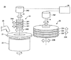
ここでまず、試し研削工程、及び外周面取り工程で、試し研削用ガラス基板やガラス基板の外周端面に外周面取り部を形成する際に用いることができる、磁気記録媒体用ガラス基板製造装置の構成例について、図2を用いて説明する。 Here, first, a configuration example of a glass substrate manufacturing apparatus for a magnetic recording medium that can be used when forming an outer peripheral chamfered portion on a test grinding glass substrate or an outer peripheral end surface of the glass substrate in the trial grinding step and the outer peripheral chamfering step. Will be described with reference to FIG.
図2は磁気記録媒体用ガラス基板製造装置であって、特に外周端面、及び内周端面に面取り部を形成することができる面取り部形成装置を模式的に示したものである。 FIG. 2 schematically shows a chamfered portion forming apparatus capable of forming chamfered portions on the outer peripheral end surface and the inner peripheral end surface, which is a glass substrate manufacturing apparatus for a magnetic recording medium.
図2に示したように面取り部形成装置20は、外周面取り部を形成するドーナツ形状を有するガラス基板21を保持するテーブル22、外周端面研削用砥石23を有することができる。また、内周端面研削用砥石24を有することもできる。
As shown in FIG. 2, the chamfered
そして、テーブル22に載置、保持されるドーナツ形状を有するガラス基板21の外周端面を、外周端面研削用砥石23で研削して面取りを行うことができる。また、テーブル22に載置、保持されるドーナツ形状を有するガラス基板21の内周端面について、内周端面研削用砥石24で研削して面取りを行うこともできる。
Then, the outer peripheral end surface of the glass substrate 21 having a donut shape placed and held on the table 22 can be chamfered by grinding with the outer peripheral end
テーブル22は、上面に載置されるドーナツ形状を有するガラス基板21を吸着して保持することができる。テーブル22は、回転可能に設けられており、テーブル22が回転することで、保持するドーナツ形状を有するガラス基板21も回転させることができる。 The table 22 can adsorb and hold the glass substrate 21 having a donut shape placed on the upper surface. The table 22 is rotatably provided, and the glass substrate 21 having a donut shape to be held can be rotated by rotating the table 22.
なお、ドーナツ形状を有するガラス基板21は、テーブル22のみにより保持される方法に限定されるものではない。例えば、テーブル22の上部に、円筒状の上側ホルダをテーブル22に対向するように設け、テーブル22と上側ホルダとの間でドーナツ形状を有するガラス基板21を挟み込んで固定するように構成することもできる。 Note that the glass substrate 21 having a donut shape is not limited to the method of being held only by the table 22. For example, a cylindrical upper holder may be provided on the upper portion of the table 22 so as to face the table 22, and a glass substrate 21 having a donut shape may be sandwiched and fixed between the table 22 and the upper holder. it can.
外周端面研削用砥石23は、略円柱状の形状を有し、中心軸がドーナツ形状を有するガラス基板21の主表面に対して略直交するように設けることができる。外周端面研削用砥石23の外周面には砥粒が固定されており、中心軸に直交する円環溝状の研削面231を中心軸方向に沿って複数設けることができる。
The outer peripheral end face grinding
外周端面研削用砥石23は、中心軸を回転軸Rとして回転可能に設けられると共に、回転軸方向であるブロック矢印23Aの方向、及び回転軸方向に直交する方向であるブロック矢印23Bの方向に外周端面研削用砥石移動手段232により移動可能に設けられる。
The outer peripheral
外周端面研削用砥石23は、何れかの研削面231がドーナツ形状を有するガラス基板21の外周端面に接触する位置に移動して回転し、テーブル22と共に回転するドーナツ形状を有するガラス基板21の外周端面を研削して面取りを行うことができる。このため、円環溝状の研削面231は、外周端面研削用砥石23の中心軸を通り、該中心軸と平行な断面において、ドーナツ形状を有するガラス基板21の面取り後の外周端面の形状に対応した形状を有することができる。
The outer peripheral end
内周端面研削用砥石24は、略円柱状の形状を有し、中心軸がドーナツ形状を有するガラス基板21の主表面に対して略直交するように設けることができる。内周端面研削用砥石24の外周面には砥粒が固定されており、中心軸に直交する円環溝状の研削面241を中心軸方向にそって複数設けることができる。
The inner peripheral end face grinding
内周端面研削用砥石24は、中心軸を回転軸Rとして回転可能に設けられると共に、回転軸方向であるブロック矢印24Aの方向、及び回転軸方向に直交する方向であるブロック矢印24Bの方向に内周端面研削用砥石移動手段242により移動可能に設けられる。内周端面研削用砥石24は、何れかの研削面241がドーナツ形状を有するガラス基板21の内周端面に接触する位置に移動して回転し、テーブル22と共に回転するドーナツ形状を有するガラス基板21の内周端面を研削して面取りを行うことができる。このため、円環溝状の研削面241は、内周端面研削用砥石24の中心軸を通り、該中心軸と平行な断面において、ドーナツ形状を有するガラス基板21の面取り後の内周端面の形状に対応した形状を有することができる。
The inner peripheral end face grinding
なお、面取り部形成装置20は、上述の部材以外にも必要に応じて各種部材を有することができ、例えば研削液を供給する研削液供給ノズル25を有することができる。研削液供給ノズル25は、例えば研削液をドーナツ形状を有するガラス基板21と、外周端面研削用砥石23、及び内周端面研削用砥石24との間に供給することができる。
The chamfered
また、既述の外周端面研削用砥石移動手段232や、内周端面研削用砥石移動手段242を制御し、各砥石の位置を制御する砥石位置制御手段26等を有することができる。 Further, it is possible to have the grindstone position control means 26 for controlling the position of each grindstone by controlling the outer peripheral end face grinding grindstone moving means 232 and the inner peripheral end face grinding grindstone moving means 242 described above.
なお、外周端面研削用砥石23や、内周端面研削用砥石24は、テーブル22上にドーナツ形状を有するガラス基板21を搬出入する際、ドーナツ形状を有するガラス基板の搬送経路に干渉しない様、研削時とは異なる場所に移動できる。このため、砥石位置制御手段26は、その内部、または外部に、外周端面研削用砥石23や、内周端面研削用砥石24の位置情報等を記憶させておく記憶手段を有することもできる。
The outer peripheral end
本実施形態の磁気記録媒体用ガラス基板の製造方法においては、少なくとも一方の外周面取り部の面取り幅を複数の測定点で測定した場合の測定値の最大値と、最小値との差が10μm以下である磁気記録媒体用ガラス基板を製造することができる。 In the method for manufacturing a glass substrate for a magnetic recording medium of the present embodiment, the difference between the maximum value and the minimum value when the chamfer width of at least one outer peripheral chamfer is measured at a plurality of measurement points is 10 μm or less. It is possible to produce a glass substrate for a magnetic recording medium.
そして、少なくとも一方の外周面取り部の面取り幅を複数の測定点で測定した場合の測定値の最大値と、最小値との差を10μm以下とするため、外周面取り工程を行う際、外周面取り工程に供するドーナツ形状を有するガラス基板21と、外周端面研削用砥石23とが適切な配置になっていることが好ましい。
And in order to make the difference between the maximum value and the minimum value of the measured value when measuring the chamfer width of at least one outer peripheral chamfered portion at a plurality of measurement points to 10 μm or less, the outer peripheral chamfering step It is preferable that the glass substrate 21 having a donut shape and the outer peripheral
そこで本実施形態の磁気記録媒体用ガラス基板の製造方法は、図3に示すフローチャートに従って実施することができる。 Therefore, the method for manufacturing the glass substrate for a magnetic recording medium of the present embodiment can be carried out according to the flowchart shown in FIG.
まず、外周面取り工程を実施する前に試し研削工程S31を実施できる。試し研削工程S31では、ドーナツ形状を有し、一対の主表面と、外周端面と、内周端面とを有する試し研削用ガラス基板を用い、外周面取り工程でも用いる、例えば上述の面取り部形成装置20を用いて、一対の外周面取り部を形成できる。 First, the trial grinding step S31 can be performed before the outer peripheral chamfering step is performed. In the trial grinding step S31, a glass substrate for trial grinding having a donut shape and having a pair of main surfaces, an outer peripheral end surface, and an inner peripheral end surface is used in the outer peripheral chamfering step. Can be used to form a pair of outer peripheral chamfers.
なお、試し研削用ガラス基板は、磁気記録媒体用ガラス基板を製造するために外周面取り工程に供するガラス基板と同じサイズ、形状、材質を有することが好ましい。 In addition, it is preferable that the glass substrate for trial grinding has the same size, shape, and material as the glass substrate used for an outer peripheral chamfering process in order to manufacture the glass substrate for magnetic recording media.
また、図1(A)を用いて説明したように、磁気記録媒体用ガラス基板においては、内周端面にも面取り部を形成することができる。このため、試し研削工程S31では、外周面取り部を形成する際にあわせて内周面取り部も形成することができる。面取り部形成装置20により外周面取り部や、内周面取り部を形成する方法について既に説明したので、ここでは説明を省略する。
Further, as described with reference to FIG. 1A, in the glass substrate for a magnetic recording medium, a chamfered portion can also be formed on the inner peripheral end surface. For this reason, in trial grinding process S31, when forming an outer peripheral chamfered part, an inner peripheral chamfered part can also be formed. Since the method for forming the outer peripheral chamfered portion and the inner peripheral chamfered portion by the chamfered
次いで、外周面取り部評価工程S32として、得られた試し研削用ガラス基板の一対の外周面取り部のうち、少なくとも一方の外周面取り部の面取り幅の分布を評価することができる。この際の面取り幅の評価手段については特に限定されるものではなく、例えば外周面取り部の面取り幅を複数の測定点で測定できる手段であればよい。 Next, as the outer peripheral chamfered portion evaluation step S32, the distribution of the chamfer width of at least one outer peripheral chamfered portion of the pair of outer peripheral chamfered portions of the obtained glass substrate for trial grinding can be evaluated. The means for evaluating the chamfer width at this time is not particularly limited, and may be any means that can measure the chamfer width of the outer peripheral chamfered portion at a plurality of measurement points, for example.
なお、試し研削用ガラス基板についても、図1(A)を用いて説明した磁気記録媒体用ガラス基板の場合と同様に、一方の主表面側と、他方の主表面側と、にそれぞれ外周面取り部を設けることができ、一対の外周面取り部を有することができる。しかし、試し研削用ガラス基板が、一対の外周面取り部を有する場合、該一対の外周面取り部は外周端面研削用砥石により同時に形成されているため、その面取り幅の分布はほぼ同じになる。 As for the glass substrate for trial grinding, as in the case of the glass substrate for magnetic recording medium described with reference to FIG. 1 (A), the outer peripheral chamfering is performed on one main surface side and the other main surface side, respectively. A part can be provided and it can have a pair of peripheral chamfers. However, when the glass substrate for trial grinding has a pair of outer peripheral chamfered portions, the pair of outer peripheral chamfered portions are simultaneously formed by the outer peripheral end surface grinding grindstone, and therefore the distribution of the chamfer widths is almost the same.
このため、外周面取り部評価工程では、上述のように少なくとも一方の外周面取り部の面取り幅について複数の測定点で測定すればよい。すなわち、例えば一方の外周面取り部について、外周に沿って選択した任意の複数の測定点で面取り幅を測定できる。特に、より正確に面取り幅の分布を測定するため、両方の外周面取り部について、各外周面取り部において外周に沿って選択した任意の複数の測定点で面取り幅を測定することがより好ましい。 For this reason, in the outer peripheral chamfered portion evaluation step, the chamfer width of at least one outer peripheral chamfered portion may be measured at a plurality of measurement points as described above. That is, for example, for one outer peripheral chamfer, the chamfer width can be measured at a plurality of arbitrary measurement points selected along the outer periphery. In particular, in order to more accurately measure the distribution of the chamfer width, it is more preferable to measure the chamfer width at any of a plurality of measurement points selected along the outer periphery of each of the outer peripheral chamfered portions.
外周面取り部評価工程S32において、外周面取り部の面取り幅を測定する測定点の数は特に限定されるものではないが、例えば測定点の数は4点以上であることが好ましく、20点以上であることがより好ましい。 In the outer peripheral chamfered portion evaluation step S32, the number of measurement points for measuring the chamfer width of the outer peripheral chamfered portion is not particularly limited. For example, the number of measurement points is preferably four or more, and more than twenty. More preferably.
ただし、生産性の観点から外周面取り部の面取り幅を測定する測定点の数は360点以下であることが好ましく、180点以下であることがより好ましい。 However, from the viewpoint of productivity, the number of measurement points for measuring the chamfer width of the outer peripheral chamfered portion is preferably 360 points or less, and more preferably 180 points or less.
なお、ここでの測定点の数とは、1つの外周面取り部の面取り幅を測定する際の測定点の数を意味している。 Note that the number of measurement points here means the number of measurement points when measuring the chamfer width of one outer peripheral chamfer.
また、測定点間の距離は一定であることが好ましい。このため、例えば一の測定点と、試し研削用ガラス基板の中心と、上記一の測定点に隣接する測定点とで形成する角度は、360°を測定点の数で除した値となっていることが好ましい。 Moreover, it is preferable that the distance between measurement points is constant. For this reason, for example, the angle formed by one measurement point, the center of the glass substrate for trial grinding, and the measurement point adjacent to the one measurement point is a value obtained by dividing 360 ° by the number of measurement points. Preferably it is.
次いで、外周端面研削用砥石位置補正工程S33において、上記外周面取り部評価工程S32での評価結果に基づいて外周端面研削用砥石23の位置の補正を実施できる。
Next, in the outer peripheral edge grinding wheel position correcting step S33, the position of the outer peripheral
なお、外周端面研削用砥石23は、テーブル22上にドーナツ形状を有するガラス基板21を搬出入する際、ドーナツ形状を有するガラス基板21の搬送経路と干渉しないように、外周面取り工程時とは異なる位置に移動している。このため、外周端面研削用砥石位置補正工程S33では、外周面取り工程における外周端面研削用砥石の適切な位置を算出し、その結果、すなわち端面研削用砥石の適切な位置の位置情報を記憶手段に記憶させておくことができる。
The outer peripheral
外周端面研削用砥石位置補正工程S33では、まず外周面取り部評価工程S32での評価結果から、例えば外周面取り工程S35における外周端面研削用砥石23の上下方向の位置について適切な位置の位置情報を算出することができる。
In the outer peripheral edge grinding wheel position correcting step S33, first, from the evaluation result in the outer peripheral chamfered portion evaluation step S32, for example, position information of an appropriate position is calculated for the vertical position of the outer peripheral
これは、ドーナツ形状を有するガラス基板21に対する、外周端面研削用砥石23の上下方向の位置、具体的には研削面231の上下方向の位置のずれが、外周面取り部の面取り幅を複数の測定点で測定した際の測定値の最大値と最小値との差が大きくなる主な原因だからである。
This is because the vertical position of the outer peripheral
なお、ここでの上下方向とは、テーブル22上に保持されたドーナツ形状を有するガラス基板21の主表面と垂直な方向を意味する。 Here, the vertical direction means a direction perpendicular to the main surface of the glass substrate 21 having a donut shape held on the table 22.
また、外周面取り工程S35における外周端面研削用砥石23の上下方向の適切な位置の位置情報は、少なくとも一方の外周面取り部の面取り幅を複数の測定点で測定した際に、測定値の最大値と最小値との差が10μm以下になるように算出することが好ましい。特に、8μm以下となるように算出することがより好ましく、5μm以下となるように算出することがさらに好ましい。
Further, the position information of the appropriate position in the vertical direction of the outer peripheral end
算出した外周端面研削用砥石の適切な位置の位置情報を外周面取り工程S35における外周端面研削用砥石の適切な位置として更新して、例えば砥石位置制御手段26の内部、または外部に設けた記憶手段に記憶させることができる。そして、後述する外周面取り工程S35において、砥石位置制御手段26は、外周端面研削用砥石23を、更新した位置情報に基づいて、外周端面研削用砥石移動手段232により移動させ、面取りを行うことができる。
The calculated position information of the appropriate position of the outer peripheral end face grinding wheel is updated as the appropriate position of the outer peripheral end face grinding wheel in the outer peripheral chamfering step S35, for example, storage means provided inside or outside the grindstone position control means 26 Can be memorized. In the outer peripheral chamfering step S35, which will be described later, the grindstone position control means 26 moves the outer peripheral end
なお、外周端面研削用砥石位置補正工程S33において、外周面取り部評価工程S32での評価結果から、外周面取り工程S35における外周端面研削用砥石23の上下方向の適切な位置を算出し、記憶させる例について説明したが、係る形態に限定されない。外周面取り工程S35における外周端面研削用砥石23の上下方向の適切な位置に加えて、または替えて外周面取り工程S35における外周端面研削用砥石23の回転軸Rの適切な角度を算出し、記憶手段に該角度情報を記憶させてもよい。
An example of calculating and storing an appropriate vertical position of the outer peripheral end
この場合、後述する外周面取り工程S35において、砥石位置制御手段26は、外周端面研削用砥石23を、記憶手段に記憶した位置情報および/または角度情報に基づいて、外周端面研削用砥石移動手段232により移動させ、面取りを行うことができる。 In this case, in the outer peripheral chamfering step S35 described later, the grindstone position control means 26 uses the outer peripheral end face grinding grindstone moving means 232 based on the position information and / or angle information stored in the storage means. The chamfering can be performed by moving.
また、図3に示したように、外周端面研削用砥石位置補正工程S33に加えて、または替えて、テーブル22の位置を補正するテーブル位置補正工程S33´を実施することもできる。テーブル位置補正工程S33´では、例えば外周面取り部評価工程S32での評価結果から、外周面取り工程S35におけるテーブル22の適切な位置および/または回転軸の適切な角度を算出することができる。 Moreover, as shown in FIG. 3, in addition to or instead of the outer peripheral end face grinding wheel position correcting step S33, a table position correcting step S33 ′ for correcting the position of the table 22 may be performed. In the table position correction step S33 ′, for example, an appropriate position of the table 22 and / or an appropriate angle of the rotating shaft in the outer peripheral chamfering step S35 can be calculated from the evaluation result in the outer peripheral chamfered portion evaluation step S32.
そして、テーブル22の位置が適切な位置となるように、および/またはテーブル22の回転軸が適切な角度となるように補正することができる。 And it can correct | amend so that the position of the table 22 may become an appropriate position, and / or the rotation axis of the table 22 may become an appropriate angle.
なお、算出したテーブル22の適切な位置および/または回転軸の適切な角度を外周面取り工程S35におけるテーブル22の適切な位置および/または回転軸の角度の情報として更新して、図示しないテーブル位置制御手段等が有する記憶手段に記憶させてもよい。そして、外周面取り工程S35において、更新した位置情報等に基づいて、テーブル22を図示しないテーブル移動手段により移動させ、面取りを行うこともできる。 The calculated appropriate position of the table 22 and / or the appropriate angle of the rotation axis is updated as information on the appropriate position of the table 22 and / or the angle of the rotation axis in the outer peripheral chamfering step S35, and table position control (not shown) is performed. You may memorize | store in the memory | storage means which a means etc. have. In the outer peripheral chamfering step S35, the table 22 can be moved by a table moving means (not shown) based on the updated position information or the like to perform chamfering.
外周端面研削用砥石位置補正工程S33、および/またはテーブル位置補正工程S33´を終了後は、例えば外周端面研削用砥石位置確認工程S34を実施することもできる。外周端面研削用砥石位置確認工程S34では、例えば既述の試し研削工程S31、及び外周面取り部評価工程S32と同様に、確認用ガラス基板に一対の外周面取り部を形成することができる。そして、少なくとも一方の外周面取り部の面取り幅を複数の測定点で測定し、測定値の最大値と、最小値との差を評価できる。 After the outer peripheral end surface grinding wheel position correcting step S33 and / or the table position correcting step S33 'is completed, for example, an outer peripheral end surface grinding wheel position checking step S34 may be performed. In the outer peripheral end surface grinding wheel position confirmation step S34, a pair of outer peripheral chamfered portions can be formed on the glass substrate for confirmation, for example, in the same manner as the aforementioned trial grinding step S31 and outer peripheral chamfered portion evaluation step S32. Then, the chamfer width of at least one of the outer peripheral chamfers is measured at a plurality of measurement points, and the difference between the maximum value and the minimum value of the measurement values can be evaluated.
なお、本工程で確認用ガラス基板に外周面取り部を形成する際は、外周端面研削用砥石23および/またはテーブル22の、位置および/または回転軸の角度を、外周端面研削用砥石位置補正工程S33および/またはテーブル位置補正工程S33´で算出した位置情報や角度情報に基づいて補正した状態で実施できる。また、確認用ガラス基板としては、例えば既述の試し研削用ガラス基板と同様のサイズ、形状、材質のガラス基板を用いることができる。
In this step, when the outer peripheral chamfered portion is formed on the glass substrate for confirmation, the position of the outer peripheral end
そして、その結果から、テーブル22上のドーナツ形状を有するガラス基板21に対する、補正後の外周端面研削用砥石23の位置が適切であるか確認できる。すなわち、測定を行った外周面取り部の面取り幅の、測定値の最大値と、最小値との差が所定の範囲内であれば、テーブル22上のドーナツ形状を有するガラス基板21に対する外周端面研削用砥石23の補正後の位置が適切であると確認できる。
And from the result, it can confirm whether the position of the
ドーナツ形状を有するガラス基板に対する外周端面研削用砥石23の位置が適切でない場合、再度試し研削工程S31から実施できる。
When the position of the
なお、図3中破線で示したように、外周端面研削用砥石位置確認工程S34を実施せずに、外周面取り工程S35を実施することもできる。 In addition, as shown with the broken line in FIG. 3, outer peripheral chamfering process S35 can also be implemented, without implementing outer peripheral end surface grinding wheel position confirmation process S34.
次いで、外周面取り工程S35を実施することができる。 Next, the outer peripheral chamfering step S35 can be performed.
外周面取り工程S35では、テーブル22上にドーナツ形状を有するガラス基板21を載置し、外周端面研削用砥石位置補正工程S33で算出し、砥石位置制御手段26等が有する記憶手段に記憶させた位置情報および/または角度情報に基づいて外周端面研削用砥石23を移動させることができる。そして、ドーナツ形状を有するガラス基板21の外周端面と、外周端面研削用砥石23の研削面231とが接触した状態で、テーブル22、及び外周端面研削用砥石23を回転軸に沿って回転させることで、面取りを行うことができる。
In the outer peripheral chamfering step S35, the glass substrate 21 having a donut shape is placed on the table 22, calculated in the outer peripheral end surface grinding wheel position correcting step S33, and stored in the storage means included in the grinding wheel position control means 26 and the like. Based on the information and / or the angle information, the outer peripheral end
なお、既述のようにテーブル位置補正工程S33´を実施した場合には、面取りを実施する前に、テーブル位置補正工程S33´で算出したテーブルの位置および/または回転軸の角度となるようにテーブル22を移動させることもできる。 When the table position correction step S33 ′ is performed as described above, the table position and / or the rotation axis angle calculated in the table position correction step S33 ′ are set before chamfering. The table 22 can also be moved.
このようにして、外周面取り工程に供するドーナツ形状を有するガラス基板と、外周端面研削用砥石とが、適切な配置となるように補正した後で、外周面取り工程を実施することができる。これにより、外周面取り部の面取り幅を複数の測定点で測定した場合の測定値の最大値と、最小値との差、すなわち、外周面取り部の面取り幅のばらつきを抑制した磁気記録媒体用ガラス基板を得ることができる。 In this way, the outer peripheral chamfering step can be carried out after correcting the glass substrate having a donut shape to be used for the outer peripheral chamfering step and the outer peripheral end surface grinding grindstone to have an appropriate arrangement. Thereby, the glass for the magnetic recording medium in which the difference between the maximum value and the minimum value of the measured value when measuring the chamfer width of the outer peripheral chamfered portion at a plurality of measurement points, that is, the variation in the chamfer width of the outer peripheral chamfered portion is suppressed. A substrate can be obtained.
なお、複数枚の磁気記録媒体用ガラス基板を製造する場合、磁気記録媒体用ガラス基板の外周面取り部を形成する度に試し研削工程S31から外周端面研削用砥石位置補正工程S33までの工程を実施する必要はない。試し研削工程S31等は、例えば、製造した磁気記録媒体用ガラス基板について評価を行った際に、外周面取り部の面取り幅のばらつきが大きくなった場合や、製造条件を変更する場合、磁気記録媒体用ガラス基板製造装置の運転開始時等に実施できる。 When a plurality of glass substrates for magnetic recording media are manufactured, the steps from the trial grinding step S31 to the grinding wheel position correcting step S33 for outer peripheral end surface grinding are performed every time the outer peripheral chamfered portion of the glass substrate for magnetic recording medium is formed. do not have to. In the trial grinding step S31, for example, when the manufactured glass substrate for magnetic recording medium is evaluated, when the variation in the chamfer width of the outer peripheral chamfered portion becomes large, or when the manufacturing conditions are changed, the magnetic recording medium It can be carried out at the start of operation of the glass substrate manufacturing apparatus.
このため、一旦試し研削工程S31から外周端面研削用砥石位置補正工程S33までの工程、及び必要に応じて外周端面研削用砥石位置確認工程S34等を実施した後は、外周面取り工程S35のみを繰り返し実施することができる。 For this reason, after the trial grinding step S31 to the outer peripheral end surface grinding wheel position correcting step S33 and the outer peripheral end surface grinding wheel position confirmation step S34, etc., as necessary, only the outer peripheral chamfering step S35 is repeated. Can be implemented.
また、既述の磁気記録媒体用ガラス基板においては、一対の内周面取り部のうち、少なくとも一方の内周面取り部の面取り幅を複数の測定点で測定した場合の測定値の最大値と、最小値との差についても10μm以下であることが好ましい。 Further, in the glass substrate for magnetic recording medium described above, the maximum value of the measured value when measuring the chamfer width of at least one inner peripheral chamfered portion at a plurality of measurement points among the pair of inner peripheral chamfered portions, The difference from the minimum value is also preferably 10 μm or less.
少なくとも一方の内周面取り部の面取り幅を複数の測定点で測定した場合の測定値の最大値と、最小値との差を10μm以下とするため、内周面取り工程において、内周面取り工程に供するドーナツ形状を有するガラス基板21と、内周端面研削用砥石24とが適切な配置になっていることが好ましい。
In order to set the difference between the maximum value and the minimum value when measuring the chamfer width of at least one inner peripheral chamfered portion at a plurality of measurement points to 10 μm or less, in the inner peripheral chamfering process, It is preferable that the glass substrate 21 having a donut shape to be provided and the inner peripheral
そこで本実施形態の磁気記録媒体用ガラス基板の製造方法は、図4に示すフローチャートに従って実施することができる。 Therefore, the method for manufacturing a glass substrate for a magnetic recording medium according to this embodiment can be carried out according to the flowchart shown in FIG.
まず、上述の試し研削工程において、さらに内周端面研削用砥石により試し研削用ガラス基板の内周端面を研削し、一対の内周面取り部を形成することができる。そして、さらに以下の工程を有することもできる。 First, in the above-described trial grinding step, the inner peripheral end face of the glass substrate for trial grinding can be further ground with an inner peripheral end face grinding grindstone to form a pair of inner peripheral chamfered portions. And it can also have the following processes further.
試し研削工程後、試し研削用ガラス基板の一対の内周面取り部のうち、少なくとも一方の内周面取り部の面取り幅を複数の測定点で測定する内周面取り部評価工程。 An inner peripheral chamfer evaluation step of measuring a chamfer width of at least one inner peripheral chamfered portion at a plurality of measurement points, out of the pair of inner peripheral chamfered portions of the glass substrate for trial grinding.
内周面取り部評価工程の結果に基づいて、内周端面を研削するための内周端面研削用砥石の位置を補正する内周端面研削用砥石位置補正工程。 A grindstone position correcting step for grinding the inner peripheral end face for correcting the position of the grinding wheel for inner peripheral end face grinding for grinding the inner peripheral end face based on the result of the inner peripheral chamfered portion evaluation step.
内周端面研削用砥石位置補正工程の後に、内周端面研削用砥石により、ガラス基板の内周端面に一対の内周面取り部を形成する内周面取り工程。 An inner peripheral chamfering step of forming a pair of inner peripheral chamfered portions on the inner peripheral end surface of the glass substrate by the inner peripheral end surface grinding wheel after the inner peripheral end surface grinding wheel position correcting step.
試し研削工程S31では、ドーナツ形状を有し、一対の主表面と、外周端面と、内周端面とを有する試し研削用ガラス基板を用い、外周面取り工程でも用いる、例えば上述の面取り部形成装置20を用いて、外周面取り部に加えて内周面取り部を形成できる。 In the trial grinding step S31, a glass substrate for trial grinding having a donut shape and having a pair of main surfaces, an outer peripheral end surface, and an inner peripheral end surface is used in the outer peripheral chamfering step. In addition to the outer peripheral chamfered portion, an inner peripheral chamfered portion can be formed.
なお、試し研削用ガラス基板は、磁気記録媒体用ガラス基板を製造するために外周面取り工程、内周面取り工程に供するガラス基板と同じサイズ、形状、材質を有することが好ましい。 In addition, it is preferable that the glass substrate for trial grinding has the same size, shape, and material as the glass substrate used for an outer peripheral chamfering process and an inner peripheral chamfering process in order to manufacture the glass substrate for magnetic recording media.
試し研削工程S31において、外周面取り部、及び内周面取り部を形成した場合、得られた試し研削用ガラス基板は、既述の外周面取り部評価工程S32、及び以下に詳述する内周面取り部評価工程S42に供給することができる。 In the trial grinding step S31, when the outer peripheral chamfered portion and the inner peripheral chamfered portion are formed, the obtained glass substrate for trial grinding is the outer peripheral chamfered portion evaluation step S32 described above and the inner peripheral chamfered portion described in detail below. It can supply to evaluation process S42.
次いで、内周面取り部評価工程S42として、得られた試し研削用ガラス基板の内周面取り部の面取り幅の分布を評価することができる。この際の面取り幅の評価手段については特に限定されるものではなく、例えば少なくとも一方の内周面取り部の面取り幅を複数の測定点で測定できる手段であればよい。 Next, as the inner peripheral chamfered portion evaluation step S42, the distribution of the chamfer width of the inner peripheral chamfered portion of the obtained glass substrate for trial grinding can be evaluated. The means for evaluating the chamfer width at this time is not particularly limited, and for example, any means that can measure the chamfer width of at least one inner peripheral chamfer at a plurality of measurement points may be used.
なお、試し研削用ガラス基板についても、図1(A)を用いて説明した磁気記録媒体用ガラス基板の場合と同様に、一方の主表面側と、他方の主表面側と、にそれぞれ内周面取り部を設けることができ、一対の内周面取り部を有することができる。しかし、試し研削用ガラス基板が、一対の内周面取り部を有する場合、該一対の内周面取り部は内周端面研削用砥石により同時に形成されているため、その面取り幅の分布はほぼ同じになる。 As for the glass substrate for trial grinding, as in the case of the glass substrate for magnetic recording medium described with reference to FIG. 1 (A), the inner circumference is provided on one main surface side and the other main surface side, respectively. A chamfered portion can be provided, and a pair of inner peripheral chamfered portions can be provided. However, when the glass substrate for trial grinding has a pair of inner peripheral chamfered portions, the pair of inner peripheral chamfered portions are simultaneously formed by the inner peripheral end surface grinding grindstone, and therefore the distribution of the chamfer width is substantially the same. Become.
このため、内周面取り部評価工程では、上述のように少なくとも一方の内周面取り部の面取り幅について複数の測定点で測定すればよい。すなわち、例えば一方の内周面取り部について、内周に沿って選択した任意の複数の測定点で面取り幅を測定できる。特に、より正確に面取り幅の分布を測定するため、両方の内周面取り部について、各内周面取り部において内周に沿って選択した任意の複数の測定点で面取り幅を測定することがより好ましい。 For this reason, in the inner peripheral chamfered portion evaluation step, the chamfer width of at least one inner peripheral chamfered portion may be measured at a plurality of measurement points as described above. That is, for example, for one inner peripheral chamfer, the chamfer width can be measured at a plurality of arbitrary measurement points selected along the inner periphery. In particular, in order to measure the distribution of chamfer width more accurately, it is more possible to measure the chamfer width at any of a plurality of measurement points selected along the inner circumference in each inner chamfered portion for both inner chamfered portions. preferable.
内周面取り部評価工程S42において、内周面取り部の面取り幅を測定する測定点の数は特に限定されるものではないが、例えば測定点の数は4点以上であることが好ましく、20点以上であることがより好ましい。 In the inner peripheral chamfered portion evaluation step S42, the number of measurement points for measuring the chamfer width of the inner peripheral chamfered portion is not particularly limited. For example, the number of measurement points is preferably 4 points or more, and 20 points. More preferably.
ただし、生産性の観点から、内周面取り部の面取り幅を測定する測定点の数は360点以下であることが好ましく、180点以下であることがより好ましい。 However, from the viewpoint of productivity, the number of measurement points for measuring the chamfer width of the inner peripheral chamfered portion is preferably 360 points or less, and more preferably 180 points or less.
なお、ここでの測定点の数とは、1つの内周面取り部の面取り幅を測定する際の測定点の数を意味している。 Here, the number of measurement points means the number of measurement points when measuring the chamfer width of one inner peripheral chamfer.
測定点間の距離は一定であることが好ましい。このため、例えば一の測定点と、試し研削用ガラス基板の中心と、上記一の測定点に隣接する測定点とで形成する角度は、360°を測定点の数で除した値となっていることが好ましい。 The distance between the measurement points is preferably constant. For this reason, for example, the angle formed by one measurement point, the center of the glass substrate for trial grinding, and the measurement point adjacent to the one measurement point is a value obtained by dividing 360 ° by the number of measurement points. Preferably it is.
次いで、内周端面研削用砥石位置補正工程S43において、上記内周面取り部評価工程S42での評価結果に基づいて内周端面研削用砥石24の位置の補正を実施できる。
Next, in the inner peripheral edge grinding wheel position correction step S43, the position of the inner peripheral
なお、内周端面研削用砥石24は、テーブル22にドーナツ形状を有するガラス基板21を搬出入する際、ドーナツ形状を有するガラス基板21の搬送経路と干渉しないように、内周面取り工程時とは異なる位置に移動している。このため、内周端面研削用砥石位置補正工程S43においては、内周面取り工程における内周端面研削用砥石の適切な位置を算出し、その結果、すなわち内周端面研削用砥石の適切な位置の位置情報を記憶手段に記憶させておくことになる。
The inner peripheral end
内周端面研削用砥石位置補正工程S43では、まず内周面取り部評価工程S42での評価結果から、内周面取り工程S45における内周端面研削用砥石24の上下方向の位置について適切な位置を算出することができる。
In the inner peripheral edge grinding wheel position correcting step S43, first, an appropriate position is calculated for the vertical position of the inner peripheral
これは、ドーナツ形状を有するガラス基板21に対する、内周端面研削用砥石24の上下方向の位置、具体的には研削面241の上下方向の位置のずれが、内周面取り部の面取り幅を複数の測定点で測定した際の測定値の最大値と、最小値との差が大きくなる主な原因だからである。
This is because the position of the inner peripheral end face grinding
なお、ここでの上下方向とは、テーブル22上に保持されたドーナツ形状を有するガラス基板21の主表面と垂直な方向を意味する。 Here, the vertical direction means a direction perpendicular to the main surface of the glass substrate 21 having a donut shape held on the table 22.
また、内周面取り工程S35における内周端面研削用砥石24の上下方向の適切な位置の位置情報は、少なくとも一方の内周面取り部の面取り幅を複数の測定点で測定した際に、測定値の最大値と最小値との差が10μm以下になるように選択することが好ましい。特に、8μm以下となるように選択することがより好ましく、5μm以下となるように選択することがさらに好ましい。
Further, the position information of the appropriate position in the vertical direction of the inner peripheral end face grinding
算出した内周端面研削用砥石の適切な位置の情報を内周面取り工程S45における内周端面研削用砥石24の適切な位置として更新して、例えば砥石位置制御手段26の内部、または外部に設けた記憶手段に記憶させることができる。そして、後述する内周面取り工程S45においては、内周端面研削用砥石24を更新した位置情報に基づいて、内周端面研削用砥石移動手段242により移動させ、面取りを行うことができる。
The calculated information on the appropriate position of the inner peripheral end face grinding wheel is updated as the appropriate position of the inner peripheral end
なお、内周端面研削用砥石位置補正工程S43において、内周面取り部評価工程S42での評価結果から、内周面取り工程S45における内周端面研削用砥石24の上下方向の適切な位置を算出し、記憶させる例について説明したが、係る形態に限定されない。内周面取り工程S45における内周端面研削用砥石24の上下方向の適切な位置に加えて、または替えて、内周面取り工程S45における内周端面研削用砥石24の回転軸の適切な角度を算出し、記憶手段に該角度情報を記憶させてもよい。
In the inner peripheral edge grinding wheel position correction step S43, an appropriate vertical position of the inner peripheral
この場合、後述する内周面取り工程S45において、砥石位置制御手段26は、内周端面研削用砥石24を、記憶手段に記憶した位置情報および/または角度情報に基づいて、内周端面研削用砥石移動手段242により移動させ、面取りを行うことができる。
In this case, in the inner peripheral chamfering step S45 described later, the grindstone position control means 26 uses the inner peripheral end
また、図4に示したように、内周端面研削用砥石位置補正工程S43に加えて、または替えて、テーブル22の位置を補正するテーブル位置補正工程S43´を実施することもできる。テーブル位置補正工程S43´では、例えば内周面取り部評価工程S42での評価結果から、内周面取り工程S45におけるテーブル22の適切な位置および/または回転軸の適切な傾きを算出することができる。 Moreover, as shown in FIG. 4, in addition to or instead of the inner peripheral edge grinding grinding wheel position correcting step S43, a table position correcting step S43 ′ for correcting the position of the table 22 may be performed. In the table position correction step S43 ′, for example, an appropriate position of the table 22 and / or an appropriate inclination of the rotating shaft in the inner peripheral chamfering step S45 can be calculated from the evaluation result in the inner peripheral chamfer evaluation step S42.
そして、テーブル22の位置が適切な位置となるように、および/またはテーブル22の回転軸が適切な角度となるように補正することができる。 And it can correct | amend so that the position of the table 22 may become an appropriate position, and / or the rotation axis of the table 22 may become an appropriate angle.
なお、算出したテーブル22の適切な位置および/または回転軸の適切な傾きを内周面取り工程S45におけるテーブル22の適切な位置および/または回転軸の角度の情報として更新して、図示しないテーブル位置制御手段等が有する記憶手段に記憶させてもよい。そして、内周面取り工程S45においては、更新した位置情報等に基づいて、テーブル22を図示しないテーブル移動手段により移動させ、面取りを行うこともできる。 The calculated appropriate position of the table 22 and / or the appropriate inclination of the rotation axis is updated as information on the appropriate position of the table 22 and / or the angle of the rotation axis in the inner peripheral chamfering step S45, and the table position (not shown) You may memorize | store in the memory | storage means which a control means etc. have. In the inner peripheral chamfering step S45, the chamfering can be performed by moving the table 22 by a table moving means (not shown) based on the updated position information and the like.
ただし、外周面取り工程S35のためのテーブル位置補正工程S33´と、内周面取り工程S45のためのテーブル位置補正工程S43´とは、実施する場合、いずれか一方のみを実施することが好ましい。これは、テーブル位置についての制御内容が一致しない恐れがあるからである。 However, when performing table position correction process S33 'for outer periphery chamfering process S35, and table position correction process S43' for inner periphery chamfering process S45, it is preferable to implement only one. This is because the control content for the table position may not match.
そして、例えば外周面取り工程S35のためにテーブル位置補正工程S33´を実施した場合は、補正後のテーブル位置に対応するように、内周端面研削用砥石位置補正工程S43を実施することが好ましい。また、内周面取り工程S45のためにテーブル位置補正工程S43´を実施した場合は、補正後のテーブル位置に対応するように外周端面研削用砥石位置補正工程S33を実施することが好ましい。 For example, when the table position correcting step S33 ′ is performed for the outer peripheral chamfering step S35, it is preferable to perform the inner peripheral end surface grinding wheel position correcting step S43 so as to correspond to the corrected table position. In addition, when the table position correcting step S43 ′ is performed for the inner peripheral chamfering step S45, it is preferable to perform the outer peripheral end surface grinding wheel position correcting step S33 so as to correspond to the corrected table position.
内周端面研削用砥石位置補正工程S43、および/またはテーブル位置補正工程S43´を終了後は、例えば内周端面研削用砥石位置確認工程S44を実施することもできる。内周端面研削用砥石位置確認工程S44では、例えば既述の試し研削工程S31、及び内周面取り部評価工程S42と同様に、まず確認用ガラス基板に一対の内周面取り部を形成することができる。そして、少なくとも一方の内周面取り部の面取り幅を複数の測定点で測定し、測定値の最大値と、最小値との差を評価できる。 After finishing the inner peripheral end surface grinding wheel position correcting step S43 and / or the table position correcting step S43 ', for example, an inner peripheral end surface grinding wheel position checking step S44 may be performed. In the inner peripheral end face grinding wheel position confirmation step S44, for example, a pair of inner peripheral chamfered portions is first formed on the glass substrate for confirmation, as in the above-described trial grinding step S31 and inner peripheral chamfered portion evaluation step S42. it can. Then, the chamfer width of at least one of the inner peripheral chamfers is measured at a plurality of measurement points, and the difference between the maximum value and the minimum value of the measurement values can be evaluated.
なお、本工程で確認用ガラス基板に内周面取り部を形成する際は、内周端面研削用砥石24および/またはテーブル22の、位置および/または回転軸の角度を、内周端面研削用砥石位置補正工程S43および/またはテーブル位置補正工程S43´で算出した位置情報や角度情報に基づいて補正した状態で実施できる。また、確認用ガラス基板としては、例えば既述の試し研削用ガラス基板と同様のサイズ、形状、材質のガラス基板を用いることができる。
In this step, when the inner peripheral chamfered portion is formed on the glass substrate for confirmation, the position of the inner peripheral end
そして、その結果から、テーブル22上のドーナツ形状を有するガラス基板に対する、補正後の内周端面研削用砥石24の位置が適切であるか確認できる。すなわち、測定を行った内周面取り部の面取り幅の、測定値の最大値と、最小値との差が所定の範囲内であれば、テーブル22上のドーナツ形状を有するガラス基板21に対する内周端面研削用砥石24の補正後の位置が適切であると確認できる。
Then, from the result, it can be confirmed whether the position of the corrected grinding
ドーナツ形状を有するガラス基板に対する内周端面研削用砥石24の位置が適切でない場合、再度試し研削工程S31から実施できる。
When the position of the
なお、図4中破線で示したように、内周端面研削用砥石位置確認工程S44を実施せずに、内周面取り工程S45を実施することもできる。また、外周端面研削用砥石位置確認工程S34を実施する場合には、同じ確認用ガラス基板を用いて、同時に内周端面研削用砥石位置確認工程S44工程を実施することもできる。 In addition, as shown with the broken line in FIG. 4, the inner peripheral chamfering step S45 can be performed without performing the inner peripheral end surface grinding wheel position confirmation step S44. Further, when the outer peripheral end surface grinding wheel position confirmation step S34 is performed, the inner peripheral end surface grinding wheel position confirmation step S44 can be simultaneously performed using the same confirmation glass substrate.
次いで、内周面取り工程S45を実施することができる。 Next, the inner peripheral chamfering step S45 can be performed.
内周面取り工程S45では、テーブル22上にドーナツ形状を有するガラス基板21を載置し、内周端面研削用砥石位置補正工程S43で算出し、砥石位置制御手段26等が有する記憶手段に記憶させた位置情報および/または角度情報に基づいて、内周端面研削用砥石24を移動させることができる。そして、ドーナツ形状を有するガラス基板21の内周端面と、内周端面研削用砥石24の研削面241とが接触した状態で、テーブル22、及び内周端面研削用砥石24を回転軸に沿って回転させることで、面取りを行うことができる。
In the inner peripheral chamfering step S45, the glass substrate 21 having a donut shape is placed on the table 22, calculated in the inner peripheral edge grinding grinding wheel position correcting step S43, and stored in the storage means included in the grinding wheel position control means 26 or the like. On the basis of the position information and / or the angle information, the inner peripheral
なお、既述のようにテーブル位置補正工程S43´を実施した場合には、面取りを実施する前に、テーブル位置補正工程S43´で算出したテーブルの位置および/または回転軸の角度となるようにテーブル22を移動させることもできる。 When the table position correction step S43 ′ is performed as described above, the table position and / or the rotation axis angle calculated in the table position correction step S43 ′ is set before the chamfering is performed. The table 22 can also be moved.
このようにして、内周面取り工程に供するドーナツ形状を有するガラス基板と、内周端面研削用砥石とが、適切な配置となるように補正した後で、内周面取り工程を実施することができる。これにより、内周面取り部の面取り幅を複数の測定点で測定した場合の測定値の最大値と、最小値との差、すなわち、内周面取り部の面取り幅のばらつきを抑制した磁気記録媒体用ガラス基板を得ることができる。 In this way, after correcting the glass substrate having a donut shape to be used for the inner peripheral chamfering step and the inner peripheral end face grinding grindstone to be appropriately arranged, the inner peripheral chamfering step can be performed. . Thereby, the magnetic recording medium in which the difference between the maximum value and the minimum value of the measured value when the chamfered width of the inner peripheral chamfered portion is measured at a plurality of measurement points, that is, the variation in the chamfered width of the inner peripheral chamfered portion is suppressed. A glass substrate can be obtained.
なお、複数枚の磁気記録媒体用ガラス基板を製造する場合、磁気記録媒体用ガラス基板の内周面取り部を形成する度に試し研削工程S31から内周端面研削用砥石位置補正工程S43までの工程を実施する必要はない。試し研削工程S31等は、例えば、製造した磁気記録媒体用ガラス基板について評価を行った際に、内周面取り部の面取り幅のばらつきが大きくなった場合や、製造条件を変更する場合、磁気記録媒体用ガラス基板製造装置の運転開始時等に実施できる。 When manufacturing a plurality of glass substrates for magnetic recording media, every time the inner peripheral chamfered portion of the glass substrate for magnetic recording media is formed, the process from the trial grinding step S31 to the grinding wheel position correcting step S43 for inner peripheral end surface grinding. There is no need to implement. In the trial grinding step S31, for example, when the manufactured glass substrate for magnetic recording medium is evaluated, when the variation of the chamfer width of the inner peripheral chamfered portion becomes large, or when manufacturing conditions are changed, magnetic recording is performed. It can be implemented at the start of operation of the medium glass substrate manufacturing apparatus.
このため、一旦試し研削工程S31から内周端面研削用砥石位置補正工程S43までの工程、及び必要に応じて内周端面研削用砥石位置確認工程S44等を実施した後は、内周面取り工程S45のみを繰り返し実施することができる。 For this reason, once the process from the trial grinding step S31 to the inner peripheral end surface grinding wheel position correcting step S43 and the inner peripheral end surface grinding wheel position confirmation step S44 are performed as necessary, the inner peripheral chamfering step S45. Only can be repeated.
なお、外周面取り工程S35と、内周面取り工程S45とは、例えば図2に示した面取り部形成装置20により、同時に実施することができる。
Note that the outer peripheral chamfering step S35 and the inner peripheral chamfering step S45 can be performed simultaneously by, for example, the chamfered
このように、面取り工程が図4に示したフロー図に従って、既述の試し研削工程S31から内周面取り工程S45を含む場合、内周端面研削用砥石が、内周面取り工程に供するドーナツ形状を有するガラス基板に対して適切な配置となるように、位置を補正できる。このため、得られる磁気記録媒体用ガラス基板の内周面取り部は、その面取り幅のばらつきを抑制することができる。そして、内周面取り工程後、主表面研磨工程に供した場合に得られる磁気記録媒体用ガラス基板について、主表面と内周面取り部との間に微細な疵が発生することを抑制できる。 As described above, when the chamfering step includes the inner peripheral chamfering step S45 from the above-described trial grinding step S31 according to the flowchart shown in FIG. 4, the inner peripheral end face grinding grindstone has a donut shape to be used for the inner peripheral chamfering step. The position can be corrected so as to be appropriately arranged with respect to the glass substrate. For this reason, the inner peripheral chamfered portion of the obtained glass substrate for a magnetic recording medium can suppress variation in the chamfer width. And it can suppress that a fine wrinkle generate | occur | produces between a main surface and an internal peripheral chamfering part about the glass substrate for magnetic recording media obtained when it uses for a main surface grinding | polishing process after an internal peripheral chamfering process.
本実施形態の磁気記録媒体用ガラス基板の製造方法は、ここまで説明した工程に限定されるものではなく、例えば以下の工程1〜工程5を含むことができる。
(工程1)ガラス素板から、中央部に円孔を有する円板形状のガラス基板に加工する形状付与工程。
(工程2)ガラス基板の内周と外周の端面部分の面取りを行う面取り工程。
(工程3)ガラス基板の端面(内周端面及び外周端面)を研磨する端面研磨工程。
(工程4)ガラス基板の主表面を研磨する主表面研磨工程。
(工程5)ガラス基板を洗浄して乾燥する洗浄・乾燥工程。
The manufacturing method of the glass substrate for magnetic recording media of this embodiment is not limited to the process demonstrated so far, For example, the following processes 1-process 5 can be included.
(Step 1) A shape imparting step of processing from a glass base plate into a disc-shaped glass substrate having a circular hole in the center.
(Step 2) A chamfering step for chamfering the inner surface and the outer edge of the glass substrate.
(Step 3) An end surface polishing step for polishing the end surfaces (the inner peripheral end surface and the outer peripheral end surface) of the glass substrate.
(Step 4) A main surface polishing step for polishing the main surface of the glass substrate.
(Step 5) A cleaning / drying step of cleaning and drying the glass substrate.
上記工程は記載した順番に行う必要はなく、例えば、形状付与工程の前に主表面研磨工程を行ってもよい。また、各工程は1回ずつに限定されるものではなく、要求されるガラス基板の仕様等に応じて任意の回数実施することができる。例えば、形状付与工程後に主表面研磨工程を行い、その後に面取り工程と端面研磨工程を行った後、再度主表面研磨工程を実施することもできる。 It is not necessary to perform the said process in the order described, for example, you may perform a main surface polishing process before a shape provision process. Further, each step is not limited to one time, and can be performed any number of times according to the required glass substrate specifications. For example, the main surface polishing step may be performed after the shape imparting step, and then the chamfering step and the end surface polishing step may be performed, and then the main surface polishing step may be performed again.
ただし、本実施形態の磁気記録媒体用ガラス基板の製造方法においては、面取り工程で外周面取り部を形成した場合に、その外周面取り部の面取り幅のばらつきを抑制できる。このため、主表面研磨工程に供した場合でも、主表面と外周面取り部との間に微細な疵が生じることを抑制できる。従って、(工程2)の面取り工程を実施した後、少なくとも一回(工程4)の主表面研磨工程を実施することが好ましい。 However, in the method for manufacturing a glass substrate for a magnetic recording medium according to the present embodiment, when the outer peripheral chamfered portion is formed in the chamfering step, variation in the chamfer width of the outer peripheral chamfered portion can be suppressed. For this reason, even when it uses for a main surface grinding | polishing process, it can suppress that a fine wrinkle arises between a main surface and an outer peripheral chamfering part. Therefore, it is preferable to perform the main surface polishing step (step 4) at least once after performing the chamfering step of (step 2).
ここで、(工程1)の形状付与工程は、フロート法、フュージョン法、プレス成形法、ダウンドロー法またはリドロー法で成形されたガラス素板を、中央部に円孔を有する円板形状のガラス基板に加工するものである。なお、用いるガラス素板は、アモルファスガラスでもよく、結晶化ガラスでもよく、ガラス基板の表層に強化層を有する強化ガラスでもよい。 Here, the shape imparting step of (Step 1) is a glass-shaped glass plate formed by a float method, a fusion method, a press molding method, a down draw method or a redraw method. The substrate is processed. The glass base plate used may be amorphous glass, crystallized glass, or tempered glass having a tempered layer on the surface layer of the glass substrate.
(工程2)の面取り工程は、図3に示したフロー図に従って実施する既述の試し研削工程S31から外周面取り工程S35を含むことができる。面取り工程を実施することで、ガラス基板の外周端面の面取りを行うことができる。 The chamfering step of (Step 2) can include the above-described trial grinding step S31 to the outer peripheral chamfering step S35 performed according to the flowchart shown in FIG. By carrying out the chamfering step, the outer peripheral end face of the glass substrate can be chamfered.
(工程2)の面取り工程はさらに、図4に示したフロー図に従って実施する既述の試し研削工程S31から内周面取り工程S45を含んでいてもよい。この場合、(工程2)の面取り工程では、ガラス基板の内周端面の面取りも行うこともできる。 The chamfering step of (Step 2) may further include the above-described trial grinding step S31 to the inner peripheral chamfering step S45 performed according to the flowchart shown in FIG. In this case, in the chamfering step of (Step 2), the inner peripheral end surface of the glass substrate can also be chamfered.
(工程3)の端面研磨工程は、ガラス基板の端面(側面部と面取り部)を端面研磨することができる。 In the end surface polishing step of (Step 3), the end surface (side surface portion and chamfered portion) of the glass substrate can be end surface polished.
(工程4)の主表面研磨工程では、例えば両面研磨装置により、ドーナツ形状を有するガラス基板の主表面に研磨液が供給され、ドーナツ形状を有するガラス基板の上下主表面を同時に研磨できる。主表面研磨工程は、1次研磨のみでもよく、1次研磨及び2次研磨を行うものでもよく、2次研磨の後に3次研磨を行うものでもよい。 In the main surface polishing step of (Step 4), the polishing liquid is supplied to the main surface of the glass substrate having a donut shape by, for example, a double-side polishing apparatus, and the upper and lower main surfaces of the glass substrate having a donut shape can be simultaneously polished. The main surface polishing step may be only primary polishing, may be primary polishing and secondary polishing, or may be tertiary polishing after secondary polishing.
なお、(工程4)の主表面研磨工程の前に、主表面のラップ(例えば遊離砥粒ラップ、固定砥粒ラップ等)が実施されてもよい。また、各工程間にガラス基板の洗浄(工程間洗浄)やガラス基板表面のエッチング(工程間エッチング)を実施してもよい。ここで、主表面のラップとは、広義の主表面研磨である。 In addition, before the main surface polishing step of (Step 4), wrapping of the main surface (for example, loose abrasive wrap, fixed abrasive wrap, etc.) may be performed. In addition, glass substrate cleaning (inter-process cleaning) and glass substrate surface etching (inter-process etching) may be performed between the processes. Here, the main surface lapping is a broad surface main surface polishing.
(工程5)の洗浄・乾燥工程は、研磨後のガラス基板を洗浄し、乾燥する工程である。具体的な洗浄方法は特に限定されるものではない。例えば、洗剤を用いたスクラブ洗浄、洗剤溶液に浸漬した状態での超音波洗浄、純水に浸漬した状態での超音波洗浄等により洗浄を行うことができる。また、乾燥方法についても特に限定されるものではなく、例えば、イソプロピルアルコール蒸気にて乾燥することができる。 The cleaning / drying step of (Step 5) is a step of cleaning and drying the polished glass substrate. A specific cleaning method is not particularly limited. For example, cleaning can be performed by scrub cleaning using a detergent, ultrasonic cleaning in a state immersed in a detergent solution, ultrasonic cleaning in a state immersed in pure water, or the like. Moreover, it does not specifically limit about the drying method, For example, it can dry with isopropyl alcohol vapor | steam.
さらに、上記各工程間にガラス基板の洗浄(工程間洗浄)やガラス基板表面のエッチング(工程間エッチング)を実施してもよい。また、ガラス基板に高い機械的強度が求められる場合、ガラス基板の表層に強化層を形成する強化工程(例えば、化学強化工程)を工程3、4で挙げた研磨工程前、または研磨工程後、あるいは研磨工程間で実施してもよい。 Further, glass substrate cleaning (inter-process cleaning) and glass substrate surface etching (inter-process etching) may be performed between the above steps. Further, when high mechanical strength is required for the glass substrate, the reinforcing step (for example, chemical strengthening step) for forming a reinforcing layer on the surface layer of the glass substrate is performed before or after the polishing step mentioned in steps 3 and 4, Or you may implement between grinding | polishing processes.
そして、上記各工程を含む製造方法により得られた磁気記録媒体用ガラス基板は主表面上に磁性層などの薄膜を形成する工程をさらに行うことによって、磁気記録媒体とすることができる。 And the glass substrate for magnetic recording media obtained by the manufacturing method including the above steps can be made into a magnetic recording medium by further performing a step of forming a thin film such as a magnetic layer on the main surface.
本実施形態の磁気記録媒体用ガラス基板の製造方法によれば、面取り工程において、予め試し研削工程を実施し、外周端面研削用砥石が、外周面取り工程に供するドーナツ形状を有するガラス基板に対して適切な配置となるように、その位置を補正できる。このため、得られる磁気記録媒体用ガラス基板の外周面取り部は、その面取り幅のばらつきを抑制することができる。 According to the method for manufacturing a glass substrate for a magnetic recording medium of the present embodiment, a trial grinding step is performed in advance in the chamfering step, and the outer peripheral end surface grinding wheel is applied to the glass substrate having a donut shape to be used for the outer peripheral chamfering step. The position can be corrected for proper placement. For this reason, the outer peripheral chamfered part of the glass substrate for magnetic recording media obtained can suppress variation in the chamfer width.
そして、外周面取り工程後、主表面研磨工程に供した場合に得られる磁気記録媒体用ガラス基板について、主表面と外周面取り部との間に微細な疵が発生することを抑制できる。
[磁気記録媒体用ガラス基板製造装置]
次に、本実施形態の磁気記録媒体用ガラス基板製造装置の一構成例について説明する。
And about the glass substrate for magnetic recording media obtained when it uses for a main surface grinding | polishing process after an outer periphery chamfering process, it can suppress that a fine wrinkle generate | occur | produces between a main surface and an outer periphery chamfering part.
[Glass substrate manufacturing equipment for magnetic recording media]
Next, a configuration example of the glass substrate manufacturing apparatus for a magnetic recording medium according to the present embodiment will be described.
なお、本実施形態の磁気記録媒体用ガラス基板製造装置について、既に説明した点については一部省略する。また、以下に説明する中で、既述の磁気記録媒体用ガラス基板の製造方法と重複する部分についても一部説明を省略する。 In addition, about the point already demonstrated about the glass substrate manufacturing apparatus for magnetic recording media of this embodiment, a part is abbreviate | omitted. Further, in the following description, a part of the description overlapping with the above-described method for manufacturing the glass substrate for a magnetic recording medium is also omitted.
本実施形態の磁気記録媒体用ガラス基板製造装置は、外周端面研削用砥石、および砥石位置制御手段を有することができる。 The apparatus for manufacturing a glass substrate for a magnetic recording medium according to this embodiment can include an outer peripheral end surface grinding wheel and a grinding wheel position control means.
なお、外周端面研削用砥石は、ドーナツ形状を有し、一対の主表面と、外周端面と、内周端面と、を有するガラス基板の外周端面に一対の外周面取り部を形成することができる。 In addition, the grindstone for outer peripheral end surface grinding has a donut shape, and can form a pair of outer peripheral chamfered portions on the outer peripheral end surface of the glass substrate having a pair of main surfaces, an outer peripheral end surface, and an inner peripheral end surface.
また、砥石位置制御手段は、上記ガラス基板と同じ形状を有する試し研削用ガラス基板に、外周端面研削用砥石により一対の外周面取り部を形成し、一対の外周面取り部のうち、少なくとも一方の外周面取り部の面取り幅を複数の測定点で測定した際の、外周面取り部の面取り幅の分布に基いて、外周端面研削用砥石の位置を制御することができる。 Further, the grinding wheel position control means forms a pair of outer peripheral chamfered portions on the glass substrate for trial grinding having the same shape as the glass substrate by an outer peripheral end surface grinding grindstone, and at least one outer periphery of the pair of outer peripheral chamfered portions. Based on the distribution of the chamfer width of the outer peripheral chamfered portion when the chamfered width of the chamfered portion is measured at a plurality of measurement points, the position of the outer peripheral end surface grinding wheel can be controlled.
本実施形態の磁気記録媒体用ガラス基板製造装置は、例えば図2に示した磁気記録媒体用ガラス基板製造装置であって、特に外周端面に面取り部を形成することができる面取り部形成装置20と同様に構成することができる。 The glass substrate manufacturing apparatus for a magnetic recording medium of the present embodiment is, for example, the glass substrate manufacturing apparatus for a magnetic recording medium shown in FIG. It can be configured similarly.
すなわち、本実施形態の磁気記録媒体用ガラス基板製造装置である、面取り部形成装置20は、外周面取り部を形成するドーナツ形状を有するガラス基板21を保持するテーブル22、外周端面研削用砥石23を有することができる。また、同時に内周端面に面取り部を形成する場合には、内周端面研削用砥石24を有することもできる。
That is, the chamfered
外周端面研削用砥石23は、中心軸を回転軸Rとして回転可能に設けられると共に、回転軸方向であるブロック矢印23Aの方向、及び回転軸方向に直交する方向であるブロック矢印23Bの方向に外周端面研削用砥石移動手段232により移動可能に設けられる。
The outer peripheral
また、外周端面研削用砥石移動手段232には、砥石位置制御手段26が接続されており、砥石位置制御手段26からの指令に応じて外周端面研削用砥石23を移動し、回転させることができる。
In addition, a grindstone position control means 26 is connected to the outer peripheral end face grinding grindstone moving means 232, and the outer peripheral end
砥石位置制御手段26は、試し研削用ガラス基板に外周端面研削用砥石23により一対の外周面取り部を形成し、一対の外周面取り部のうち、少なくとも一方の外周面取り部の面取り幅を複数の測定点で測定した際の、外周面取り部の面取り幅の分布に基いて外周端面研削用砥石の位置を制御できる。
The grindstone position control means 26 forms a pair of outer peripheral chamfered portions on the glass substrate for trial grinding with the outer peripheral end
具体的には、例えば既述の磁気記録媒体用ガラス基板の製造方法の場合と同様にして、予め、試し研削工程S31、外周面取り部評価工程S32、外周端面研削用砥石位置補正工程S33を実施しておくことができる。この際、外周端面研削用砥石位置補正工程S33で算出した、外周面取り工程S35における外周端面研削用砥石23の適切な位置の位置情報および/または回転軸の角度情報を、砥石位置制御手段26内部等に設けた記憶手段に記憶させておくことができる。
Specifically, for example, the trial grinding step S31, the outer peripheral chamfered portion evaluation step S32, and the outer peripheral end surface grinding grindstone position correcting step S33 are performed in the same manner as in the above-described method for manufacturing the glass substrate for magnetic recording medium. Can be kept. At this time, the position information of the appropriate position of the outer peripheral end
そして、ドーナツ形状を有するガラス基板21の外周面取り工程S35を実施する際には、記憶手段に記憶された位置情報および/または角度情報に基づいて、外周端面研削用砥石移動手段232により外周端面研削用砥石23を移動させる。次いで、テーブル22、及び外周端面研削用砥石23を回転させることで、外周面取り工程S35を実施できる。
When the outer peripheral chamfering step S35 of the glass substrate 21 having a donut shape is performed, the outer peripheral end surface grinding is performed by the outer peripheral end surface grinding
また、本実施形態の磁気記録媒体用ガラス基板製造装置は、砥石位置制御手段26以外に、テーブル22の位置を移動、制御する図示しないテーブル移動手段や、テーブル移動手段を制御するテーブル位置制御手段を有することもできる。この場合、テーブル位置補正工程S33´を実施し、外周面取り部評価工程S32の評価結果から外周面取り工程S35におけるテーブル22の適切な位置および/または回転軸の適切な傾きを算出することができる。さらに、テーブル位置制御手段等に設けた記憶手段に記憶させることができる。 In addition to the grindstone position control means 26, the glass substrate manufacturing apparatus for a magnetic recording medium of the present embodiment has a table moving means (not shown) that moves and controls the position of the table 22, and a table position control means that controls the table moving means. Can also be included. In this case, the table position correcting step S33 ′ can be performed, and an appropriate position of the table 22 and / or an appropriate inclination of the rotating shaft in the outer peripheral chamfering step S35 can be calculated from the evaluation result of the outer peripheral chamfered portion evaluating step S32. Further, it can be stored in storage means provided in the table position control means or the like.
そして、外周面取り工程S35を実施する際には、テーブル位置制御手段等に設けた記憶手段に記憶された情報に基づいて、テーブル移動手段によりテーブル22を所定の位置および/またはテーブル22の回転軸を所定の角度となるように移動させることができる。また、既述のように外周端面研削用砥石移動手段232により外周端面研削用砥石23を所定の位置まで移動させることができる。
When the outer peripheral chamfering step S35 is performed, the table 22 is moved to the predetermined position and / or the rotation axis of the table 22 by the table moving means based on the information stored in the storage means provided in the table position control means or the like. Can be moved at a predetermined angle. Further, as described above, the outer peripheral end
次いで、テーブル22、及び外周端面研削用砥石23を回転させることで、外周面取り工程S35を実施できる。
Next, the outer peripheral chamfering step S35 can be performed by rotating the table 22 and the outer peripheral end
以上に説明した本実施形態の磁気記録媒体用ガラス基板製造装置によれば、テーブル上に載置されたドーナツ形状を有するガラス基板の外周端面に外周面取り部を形成する際、該ドーナツ形状を有するガラス基板と、外周端面研削用砥石とを適切な位置に配置できる。このため、外周面取り部の面取り幅のばらつきを抑制した磁気記録媒体用ガラス基板を製造することができる。 According to the glass substrate manufacturing apparatus for a magnetic recording medium of the present embodiment described above, when the outer peripheral chamfered portion is formed on the outer peripheral end surface of the glass substrate having a donut shape placed on the table, the doughnut shape is formed. The glass substrate and the outer peripheral end surface grinding wheel can be arranged at appropriate positions. For this reason, the glass substrate for magnetic recording media which suppressed the dispersion | variation in the chamfering width | variety of an outer peripheral chamfering part can be manufactured.
また、本実施形態の磁気記録媒体用ガラス基板製造装置は、既述のようにさらに内周端面研削用砥石24を有することもできる。
Moreover, the glass substrate manufacturing apparatus for magnetic recording media of this embodiment can also have the
なお、内周端面研削用砥石は、ドーナツ形状を有し、一対の主表面と、外周端面と、内周端面と、を有するガラス基板の内周端面に一対の内周面取り部を形成することができる。 The grinding wheel for inner peripheral end face grinding has a donut shape and forms a pair of inner peripheral chamfered portions on the inner peripheral end face of the glass substrate having a pair of main surfaces, an outer peripheral end face, and an inner peripheral end face. Can do.
また、砥石位置制御手段は、上記ガラス基板と同じ形状を有する試し研削用ガラス基板に、内周端面研削用砥石により一対の内周面取り部を形成し、一対の内周面取り部のうち、少なくとも一方の内周面取り部の面取り幅を複数の測定点で測定した際の、内周面取り部の面取り幅の分布に基いて、内周端面研削用砥石の位置を制御することができる。 Further, the grinding wheel position control means forms a pair of inner peripheral chamfered portions with a grinding wheel for inner peripheral end surface grinding on a glass substrate for trial grinding having the same shape as the glass substrate, and at least of the pair of inner peripheral chamfered portions. Based on the distribution of the chamfer width of the inner peripheral chamfered portion when the chamfered width of one inner peripheral chamfered portion is measured at a plurality of measurement points, the position of the inner peripheral end face grinding grindstone can be controlled.
内周端面研削用砥石24は、中心軸を回転軸Rとして回転可能に設けられると共に、回転軸方向であるブロック矢印24Aの方向、及び回転軸方向に直交する方向であるブロック矢印24Bの方向に内周端面研削用砥石移動手段242により移動可能に設けられる。
The inner peripheral end face grinding
また、内周端面研削用砥石移動手段242には、砥石位置制御手段26が接続されており、砥石位置制御手段26からの指令に応じて内周端面研削用砥石24を移動し、回転させることができる。
Further, a grindstone position control means 26 is connected to the inner peripheral end face grinding grindstone moving means 242, and the inner peripheral end
砥石位置制御手段26は、試し研削用ガラス基板に内周端面研削用砥石により一対の内周面取り部を形成し、一対の内周面取り部のうち、少なくとも一方の内周面取り部の面取り幅を複数の測定点で測定した際の、内周面取り部の面取り幅の分布に基いて内周端面研削用砥石の位置を制御できる。 The grindstone position control means 26 forms a pair of inner peripheral chamfered portions on the glass substrate for trial grinding with an inner peripheral end face grinding grindstone, and sets the chamfer width of at least one inner peripheral chamfered portion of the pair of inner peripheral chamfered portions. The position of the grindstone for inner peripheral end face grinding can be controlled based on the distribution of the chamfer width of the inner peripheral chamfered portion when measured at a plurality of measurement points.
具体的には、例えば既述の磁気記録媒体用ガラス基板の製造方法の場合と同様にして、予め、試し研削工程S31、内周面取り部評価工程S42、内周端面研削用砥石位置補正工程S43を実施しておくことができる。この際、内周端面研削用砥石位置補正工程S43で算出した、内周面取り工程S45における内周端面研削用砥石の適切な位置の位置情報および/または回転軸の角度情報を、砥石位置制御手段26内部等に設けた記憶手段に記憶させておくことができる。 Specifically, for example, in the same manner as in the above-described method for manufacturing a glass substrate for magnetic recording medium, a trial grinding step S31, an inner peripheral chamfered portion evaluation step S42, and an inner peripheral end face grinding grindstone position correcting step S43 are performed in advance. Can be implemented. At this time, the position information of the appropriate position of the grinding wheel for inner peripheral end face grinding in the inner peripheral chamfering step S45 and / or the angle information of the rotating shaft calculated in the grinding wheel position correction process S43 for inner peripheral end face grinding is used as the grinding wheel position control means. 26 can be stored in storage means provided in the interior of the apparatus.
そして、ドーナツ形状を有するガラス基板21の内周面取り工程S45を実施する際には、記憶手段に記憶された位置情報および/または角度情報に基づいて、内周端面研削用砥石移動手段242により内周端面研削用砥石24を移動させる。次いで、テーブル22、及び内周端面研削用砥石24を回転させることで、内周面取り工程S45を実施できる。
Then, when the inner peripheral chamfering step S45 of the glass substrate 21 having a donut shape is performed, the inner peripheral end surface grinding grindstone moving means 242 uses the inner peripheral end surface grinding grindstone moving means 242 based on the position information and / or angle information stored in the storage means. The peripheral
このように、上記内周端面研削用砥石と、砥石位置制御手段とを備えることでテーブル上に載置されたドーナツ形状を有するガラス基板の内周端面に内周面取り部を形成する際、該ドーナツ形状を有するガラス基板と、内周端面研削用砥石とを適切な位置に配置できる。このため、内周面取り部の面取り幅のばらつきを抑制した磁気記録媒体用ガラス基板を製造することもできる。 Thus, when forming the inner peripheral chamfered portion on the inner peripheral end surface of the glass substrate having a donut shape placed on the table by providing the inner peripheral end surface grinding grindstone and the grindstone position control means, The glass substrate having a donut shape and the grinding wheel for inner peripheral end face grinding can be arranged at appropriate positions. For this reason, the glass substrate for magnetic recording media which suppressed the dispersion | variation in the chamfering width | variety of an inner peripheral chamfer part can also be manufactured.
また、本実施形態の磁気記録媒体用ガラス基板製造装置は、砥石位置制御手段26以外に、テーブル22の位置を制御する図示しないテーブル移動手段や、テーブル移動手段を制御するテーブル位置制御手段を有することもできる。この場合、テーブル位置補正工程S43´を実施し、内周面取り部評価工程S42の評価結果から内周面取り工程S45におけるテーブル22の適切な位置および/または回転軸の適切な傾きを算出することができる。さらに、テーブル位置制御手段等に設けた記憶手段に記憶させることができる。
In addition to the grindstone
そして、内周面取り工程S45を実施する際には、テーブル位置制御手段等に設けた記憶手段に記憶された情報に基づいて、テーブル移動手段によりテーブル22を所定の位置および/またはテーブル22の回転軸を所定の角度となるように移動させる。また、既述のように内周端面研削用砥石移動手段242により内周端面研削用砥石24を所定の位置まで移動させる。
When performing the inner peripheral chamfering step S45, the table 22 is moved to a predetermined position and / or rotated by the table moving means based on the information stored in the storage means provided in the table position control means or the like. The shaft is moved to a predetermined angle. Further, as described above, the inner peripheral end face grinding grindstone moving means 242 moves the inner peripheral end
次いで、テーブル22、及び内周端面研削用砥石24を回転させることで、内周面取り工程S45を実施できる。
Next, the inner peripheral chamfering step S45 can be performed by rotating the table 22 and the inner peripheral end face grinding
この場合も、テーブル上に載置されたドーナツ形状を有するガラス基板の内周端面に内周面取り部を形成する際、該ドーナツ形状を有するガラス基板と、内周端面研削用砥石とを適切な位置に配置できる。このため、内周面取り部の面取り幅のばらつきを抑制した磁気記録媒体用ガラス基板を製造することもできる。
[磁気記録媒体]
次に、本実施形態の磁気記録媒体の一構成例について説明する。
Also in this case, when forming the inner peripheral chamfered portion on the inner peripheral end face of the glass substrate having a donut shape placed on the table, the glass substrate having the donut shape and an inner peripheral end face grinding grindstone are appropriately combined. Can be placed in position. For this reason, the glass substrate for magnetic recording media which suppressed the dispersion | variation in the chamfering width | variety of an inner peripheral chamfer part can also be manufactured.
[Magnetic recording medium]
Next, a configuration example of the magnetic recording medium of this embodiment will be described.
本実施形態の磁気記録媒体は、既述の磁気記録媒体用ガラス基板を含むことができる。 The magnetic recording medium of this embodiment can include the glass substrate for magnetic recording medium described above.
本実施形態の磁気記録媒体は、既述の磁気記録媒体用ガラス基板を含むものであれば、その構成については限定されるものではないが、例えば、磁気記録媒体用ガラス基板の表面に磁性層、保護層、潤滑層を備えたものが挙げられる。 The configuration of the magnetic recording medium of the present embodiment is not limited as long as it includes the glass substrate for magnetic recording medium described above. For example, a magnetic layer is formed on the surface of the glass substrate for magnetic recording medium. , A protective layer, and a lubricating layer.
なお、磁気記録媒体には水平磁気記録方式、垂直磁気記録方式があるが、ここでは垂直磁気記録方式の場合を例に、具体的な製造方法について以下に説明する。 The magnetic recording medium includes a horizontal magnetic recording method and a vertical magnetic recording method. Here, a specific manufacturing method will be described below by taking the case of the vertical magnetic recording method as an example.
磁気記録媒体は、上述のように磁気記録媒体用ガラス基板の表面に磁性層、保護層、潤滑層を有することができる。そして、垂直磁気記録方式の場合、磁気ヘッドからの記録磁界を環流させる役割を果たす軟磁性材料からなる軟磁性下地層を配するのが一般的である。このため、磁気記録媒体用ガラス基板表面から順に、例えば、軟磁性下地層、非磁性中間層、垂直記録用磁性層、保護層、潤滑層のように積層することができる。 The magnetic recording medium can have a magnetic layer, a protective layer, and a lubricating layer on the surface of the magnetic recording medium glass substrate as described above. In the case of the perpendicular magnetic recording system, a soft magnetic underlayer made of a soft magnetic material that plays a role of circulating a recording magnetic field from a magnetic head is generally provided. For this reason, for example, a soft magnetic underlayer, a nonmagnetic intermediate layer, a perpendicular recording magnetic layer, a protective layer, and a lubricating layer can be stacked in this order from the surface of the magnetic recording medium glass substrate.
各層について以下に説明する。 Each layer will be described below.
軟磁性下地層としては例えば、CoNiFe、FeCoB、CoCuFe、NiFe、FeAlSi、FeTaN、FeN、FeTaC、CoFeB、CoZrN等が使用できる。 As the soft magnetic underlayer, for example, CoNiFe, FeCoB, CoCuFe, NiFe, FeAlSi, FeTaN, FeN, FeTaC, CoFeB, CoZrN, or the like can be used.
そして、非磁性中間層は、Ru,Ru合金等から構成される。この非磁性中間層は垂直記録用磁性層のエピタキシャル成長を容易にするための機能、及び軟磁性下地層と垂直記録用磁性層との間での磁気交換結合を断つ機能を有する。 The nonmagnetic intermediate layer is made of Ru, Ru alloy or the like. This nonmagnetic intermediate layer has a function for facilitating the epitaxial growth of the perpendicular recording magnetic layer and a function for breaking the magnetic exchange coupling between the soft magnetic underlayer and the perpendicular recording magnetic layer.
垂直記録用磁性層は、磁化容易軸が基板面に対して垂直方向を向いた磁性膜であり、少なくともCo、Ptを含むことができる。そして、高い固有媒体ノイズの原因となる粒間交換結合を低減するため、良好に隔離された微粒子構造(グラニュラー構造)とするのが良い。具体的には、CoPt系合金などに酸化物(SiO2、SiO、Cr2O3、CoO、Ta2O3、TiO2等)や、Cr、B、Cu、Ta、Zrなどを添加したものを用いるのがよい。 The perpendicular recording magnetic layer is a magnetic film having an easy axis of magnetization oriented in a direction perpendicular to the substrate surface, and can contain at least Co and Pt. In order to reduce intergranular exchange coupling that causes high intrinsic medium noise, a well-isolated fine particle structure (granular structure) is preferable. Specifically, an oxide (SiO 2 , SiO, Cr 2 O 3 , CoO, Ta 2 O 3 , TiO 2, etc.), Cr, B, Cu, Ta, Zr or the like added to a CoPt alloy or the like Should be used.
ここまで説明した軟磁性下地層、非磁性中間層、垂直記録用磁性層はインラインスパッタ法、DCマグネトロンスパッタ法などで連続的に製造することができる。 The soft magnetic underlayer, nonmagnetic intermediate layer, and perpendicular recording magnetic layer described so far can be continuously manufactured by an in-line sputtering method, a DC magnetron sputtering method, or the like.
次いで、保護層は垂直記録用磁性層の腐食を防ぎ、かつ、磁気ヘッドが媒体に接触した場合でも媒体表面の損傷を防ぐために設けられたものであり、垂直記録用磁性層の上に設けられる。保護層としてはC、ZrO2、SiO2などを含む材料を用いることができる。 Next, the protective layer is provided to prevent corrosion of the perpendicular recording magnetic layer and to prevent damage to the surface of the medium even when the magnetic head comes into contact with the medium, and is provided on the perpendicular recording magnetic layer. . As the protective layer, a material containing C, ZrO 2 , SiO 2 or the like can be used.
その形成方法としては、例えばインラインスパッタ法、CVD法、スピンコート法などを用いることができる。 As the formation method, for example, an in-line sputtering method, a CVD method, a spin coating method, or the like can be used.
保護層の表面には磁気ヘッドと記録媒体(磁気ディスク)との摩擦を低減するために、潤滑層を形成する。潤滑層は、例えばパーフルオロポリエーテル、フッ素化アルコール、フッ素化カルボン酸などを用いることができる。潤滑層についてはディップ法、スプレー法などで形成することができる。 A lubricating layer is formed on the surface of the protective layer in order to reduce friction between the magnetic head and the recording medium (magnetic disk). For the lubricating layer, for example, perfluoropolyether, fluorinated alcohol, fluorinated carboxylic acid, or the like can be used. The lubricating layer can be formed by a dip method, a spray method, or the like.
以上に説明した本実施形態の磁気記録媒体は、既述の磁気記録媒体用ガラス基板を含んでいる。すなわち、主表面と外周面取り部との間に微細な疵の少ない磁気記録媒体用ガラス基板を用いている。このため、ハードディスクドライブ等の磁気記録装置に組み込んで使用した場合でもエラーの発生を抑制することが可能になる。 The magnetic recording medium of this embodiment described above includes the glass substrate for magnetic recording medium described above. That is, a glass substrate for a magnetic recording medium with few fine wrinkles is used between the main surface and the peripheral chamfered portion. For this reason, it is possible to suppress the occurrence of errors even when incorporated in a magnetic recording device such as a hard disk drive.
以下に具体的な実施例を挙げて説明するが、本発明はこれらの実施例に限定されるものではない。 Specific examples will be described below, but the present invention is not limited to these examples.
まず、以下の実施例、比較例における、磁気記録媒体用ガラス基板の評価方法について説明する。 First, the evaluation method of the glass substrate for magnetic recording media in the following examples and comparative examples will be described.
(1)面取り幅、外周(内周)端面研削用砥石の取付振れ
以下の実施例、比較例で作製する試し研削用ガラス基板、確認用ガラス基板及び磁気記録媒体用ガラス基板の外周面取り部、及び内周面取り部について、画像寸法測定器・投影機(株式会社キーエンス社製 型式:IM6120)を用いて面取り幅を測定する。
(1) Chamfering width, mounting runout of outer peripheral (inner peripheral) end face grinding wheel The outer peripheral chamfered portion of the glass substrate for trial grinding, the glass substrate for confirmation and the glass substrate for magnetic recording medium produced in the following examples and comparative examples, And about an internal peripheral chamfering part, a chamfering width | variety is measured using an image dimension measuring device and a projector (Keyence Co., Ltd. make: model IM6120).
測定に当たっては、外周面取り部、内周面取り部それぞれにおいて、隣接する測定点と、磁気記録媒体用ガラス基板の中心とで形成する扇形の中心角が5.625°となるように測定点を定め、該測定点毎に面取り幅の測定を行う。すなわち外周面取り部、内周面取り部それぞれについて、64点の測定点で面取り幅の測定を実施する。 In measurement, the measurement points are determined so that the central angle of the sector formed by the adjacent measurement point and the center of the glass substrate for magnetic recording medium is 5.625 ° in each of the outer peripheral chamfered portion and the inner peripheral chamfered portion. The chamfer width is measured for each measurement point. That is, the chamfer width is measured at 64 measurement points for each of the outer peripheral chamfered portion and the inner peripheral chamfered portion.
なお、図1(A)を用いて説明したように、試し研削用ガラス基板、確認用ガラス基板、及び以下の実施例、比較例で作製する磁気記録媒体用ガラス基板には、外周面取り部、および内周面取り部が、上下にそれぞれ1つずつ形成されている。しかし、試し研削用ガラス基板、確認用ガラス基板、及び以下の実施例、比較例で作製する磁気記録媒体用ガラス基板においては、外周面取り部、および内周面取り部は、それぞれ面取り幅の分布が上下2つの面取り部で同じになっている。 In addition, as demonstrated using FIG. 1 (A), the glass substrate for trial grinding, the glass substrate for confirmation, and the glass substrate for magnetic recording media produced in the following examples and comparative examples have an outer peripheral chamfered portion, One inner chamfered portion is formed on each of the upper and lower portions. However, in the glass substrate for trial grinding, the glass substrate for confirmation, and the glass substrate for magnetic recording media produced in the following examples and comparative examples, the outer peripheral chamfered portion and the inner peripheral chamfered portion have a distribution of the chamfer width, respectively. The upper and lower chamfers are the same.
このため、試し研削用ガラス基板については、外周面取り部、内周面取り部について、それぞれ上下2つの面取り部のうち、一方の面取り部について面取り幅の分布の測定を実施している。 For this reason, about the glass substrate for trial grinding, the distribution of the chamfering width is measured for one of the two chamfered portions on the outer peripheral chamfered portion and the inner peripheral chamfered portion.
また、確認用ガラス基板、及び以下の実施例、比較例で作製する磁気記録媒体用ガラス基板は、外周面取り部、内周面取り部について、それぞれ上下2つの面取り部のうち、一方の面取り部の面取り幅についての、測定値の最大値と最小値との差を算出している。 In addition, the glass substrate for confirmation, and the glass substrate for magnetic recording medium produced in the following examples and comparative examples are the outer chamfered portion and the inner peripheral chamfered portion, one of the chamfered portions of the upper and lower chamfered portions. The difference between the maximum value and the minimum value of the chamfer width is calculated.
以下の各実施例、比較例では、同じ条件で磁気記録媒体用ガラス基板を複数枚作製し、任意の5枚について上述のようにして面取り幅を測定した。そして、それぞれの磁気記録媒体用ガラス基板についての面取り幅の測定結果から最大値と、最小値との差を算出し、測定した5枚の磁気記録媒体用ガラス基板のうちの面取り幅の測定値の最大値と最小値との差の最も大きい値(最大値)を表1に示す。また、測定した5枚の磁気記録媒体用ガラス基板の、面取り幅の測定値の最大値と最小値との差の標準偏差、及び平均値もあわせて表1に示す。 In each of the following Examples and Comparative Examples, a plurality of glass substrates for magnetic recording media were produced under the same conditions, and the chamfer width was measured as described above for any five sheets. Then, the difference between the maximum value and the minimum value is calculated from the measurement result of the chamfer width for each glass substrate for magnetic recording medium, and the measured value of the chamfer width of the measured five glass substrates for magnetic recording medium Table 1 shows the largest value (maximum value) of the difference between the maximum value and the minimum value. Table 1 also shows the standard deviation and the average value of the difference between the maximum value and the minimum value of the measured values of the chamfer width of the five glass substrates for magnetic recording media.
また、各実施例、比較例では、確認用ガラス基板について測定した外周面取り部、及び内周面取り部の面取り幅の分布から、磁気記録媒体用ガラス基板を作製する際の面取り工程における外周(内周)端面研削用砥石の取付振れの算出を行っている。なお、表1、表2中の垂直方向とは、研削に供したドーナツ形状を有するガラス基板の主表面と垂直な方向を、水平方向とは研削に供したドーナツ形状を有するガラス基板の主表面と平行な方向を意味する。
(2)微小疵発生率
以下の実施例、比較例で作製した磁気記録媒体用ガラス基板について、光散乱方式表面観察機(KLA Tencor社製:OSA Candela7100)を用いて、主表面と内周面取り部との間、及び主表面と外周面取り部との間について微小な疵の発生の有無について評価を行っている。
Further, in each of the examples and comparative examples, the outer periphery (inner side) in the chamfering step when producing the glass substrate for a magnetic recording medium from the distribution of the chamfer width of the outer peripheral chamfered portion and the inner peripheral chamfered portion measured for the confirmation glass substrate. Circumference) The runout of the grinding wheel for end face grinding is calculated. In Tables 1 and 2, the vertical direction is the direction perpendicular to the main surface of the glass substrate having a donut shape subjected to grinding, and the horizontal direction is the main surface of the glass substrate having a donut shape subjected to grinding. Means the direction parallel to.
(2) Micro-wrinkle generation rate For the glass substrates for magnetic recording media prepared in the following examples and comparative examples, using a light scattering surface observing device (manufactured by KLA Tencor: OSA Candela 7100), the main surface and the inner peripheral chamfer The presence or absence of the occurrence of minute wrinkles is evaluated between the two parts and between the main surface and the outer peripheral chamfered part.
各実施例、比較例では、同じ条件で5000枚の磁気記録媒体用ガラス基板を作製しており、同じ条件で作製した基板全数、もしくは不良が5枚になるまで基板を測定し、測定した磁気記録媒体用ガラス基板中の不良製品の発生率を微小疵発生率として算出している。 In each example and comparative example, 5000 glass substrates for magnetic recording media were produced under the same conditions, and the total number of substrates produced under the same conditions or the substrates were measured until there were 5 defects, and the measured magnetic properties were measured. The incidence of defective products in the glass substrate for recording media is calculated as the incidence of minute wrinkles.
表1、表2中、外周部微小疵発生率が、主表面と外周面取り部との間に微小な疵を含む磁気記録媒体用ガラス基板の発生率を意味し、内周部微小疵発生率が、主表面と内周面取り部との間に微小な疵を含む磁気記録媒体用ガラス基板の発生率を意味する。 In Tables 1 and 2, the outer peripheral fine wrinkle occurrence rate means the occurrence rate of the glass substrate for magnetic recording medium including fine wrinkles between the main surface and the outer peripheral chamfered portion, and the inner peripheral fine wrinkle occurrence rate Means the occurrence rate of a glass substrate for a magnetic recording medium including minute wrinkles between the main surface and the inner peripheral chamfered portion.
なお、主表面と内周面取り部との間の微小な疵の発生について評価している場合には、主表面と内周面取り部との間に微小な疵を含む磁気記録媒体用ガラス基板を不良として評価する。 When evaluating the generation of minute wrinkles between the main surface and the inner peripheral chamfered portion, a glass substrate for a magnetic recording medium including a minute wrinkle between the main surface and the inner peripheral chamfered portion is used. Evaluate as defective.
また、主表面と外周面取り部との間の微小な疵の発生について評価している場合には、主表面と外周面取り部との間に微小な疵を含む磁気記録媒体用ガラス基板について不良として評価する。 In addition, when evaluating the generation of minute wrinkles between the main surface and the outer peripheral chamfered portion, the glass substrate for a magnetic recording medium including the minute wrinkles between the main surface and the outer peripheral chamfered portion is regarded as defective. evaluate.
すなわち、例えば主表面と内周面取り部との間の微小な疵の発生についての評価において、不良とされたガラス基板でも、主表面と外周面取り部との間に微小な疵の発生が無ければ、主表面と外周面取り部との間の微小な疵の発生の評価においては良品と評価される。 That is, for example, in the evaluation of the generation of minute wrinkles between the main surface and the inner peripheral chamfered portion, even if the glass substrate is regarded as defective, there is no generation of minute wrinkles between the main surface and the outer peripheral chamfered portion. In the evaluation of the generation of minute wrinkles between the main surface and the outer peripheral chamfered portion, it is evaluated as a non-defective product.
なお、当初、微小疵発生率は、磁気記録媒体用ガラス基板の製造工程での検査で通常用いられるディスク表面検査装置(株式会社日立ハイテクファインシステムズ社製 型番:NS7000)を用いて評価を行った。しかし、問題となる疵が微細なため、ノイズと疵との識別とが困難であった。このため、上述の光散乱方式表面観察機を用いている。 Initially, the minute wrinkle generation rate was evaluated using a disk surface inspection device (model number: NS7000, manufactured by Hitachi High-Tech Fine Systems Co., Ltd.) that is usually used in the inspection of the glass substrate for magnetic recording media. . However, since the wrinkles in question are fine, it is difficult to distinguish between noise and wrinkles. For this reason, the above-mentioned light scattering type surface observation machine is used.
次に、各実施例、比較例における磁気記録媒体用ガラス基板の製造方法について説明する。
[実施例1]
以下の手順で磁気記録媒体用ガラス基板の作製を行う。
Next, the manufacturing method of the glass substrate for magnetic recording media in each Example and a comparative example is demonstrated.
[Example 1]
A glass substrate for a magnetic recording medium is produced according to the following procedure.
外径65mm、内径20mm、板厚0.635mmの磁気記録媒体用ガラス基板が得られるように、フロート法で成形されたSiO2を主成分とするガラス素板を、中央部に円孔を有するドーナツ形状を有するガラス基板に加工する。(形状付与工程)
このドーナツ形状を有するガラス基板の内周端面と外周端面を、面取り幅0.15mm、面取り角度45°の磁気記録媒体用ガラス基板が得られるように面取り加工を行う。(面取り工程)
なお、面取り加工は、図2に示した磁気記録媒体用ガラス基板製造装置である面取り部形成装置20を用いて実施している。
In order to obtain a glass substrate for a magnetic recording medium having an outer diameter of 65 mm, an inner diameter of 20 mm, and a plate thickness of 0.635 mm, a glass base plate mainly composed of SiO 2 formed by a float method has a circular hole in the center. Processing into a glass substrate having a donut shape. (Shaping process)
Chamfering is performed so that a glass substrate for a magnetic recording medium having a chamfering width of 0.15 mm and a chamfering angle of 45 ° is obtained between the inner peripheral end surface and the outer peripheral end surface of the glass substrate having the donut shape. (Chamfering process)
The chamfering process is performed using the chamfered
面取り加工について以下に具体的に説明する。 The chamfering process will be specifically described below.
まず、上述のドーナツ形状を有するガラス基板と同様のサイズ、形状、材質の試し研削用ガラス基板を用意する。 First, a glass substrate for trial grinding having the same size, shape and material as the glass substrate having the donut shape described above is prepared.
そして、試し研削用ガラス基板をテーブル22上に載置し、テーブル22により吸着、保持する。 Then, the glass substrate for trial grinding is placed on the table 22 and is sucked and held by the table 22.
次いで、砥石位置制御手段26からの指令により、外周端面研削用砥石移動手段232、及び内周端面研削用砥石移動手段242により、外周端面研削用砥石23、及び内周端面研削用砥石24を移動させる。この際、試し研削用ガラス基板の外周端面、及び内周端面が、それぞれ外周端面研削用砥石23の研削面231、及び内周端面研削用砥石24の研削面241に接触するように移動させている。
Next, the outer peripheral end
そして、テーブル22、外周端面研削用砥石23、及び内周端面研削用砥石24を回転させることで、試し研削用ガラス基板に一対の外周面取り部、及び一対の内周面取り部を形成する。(試し研削工程S31)
試し研削用ガラス基板に外周面取り部、及び内周面取り部を形成した後、既述の面取り幅についての評価、すなわち面取り幅の分布についての評価を実施する。(外周面取り部評価工程S32、内周面取り部評価工程S42)
外周面取り部評価工程S32、及び内周面取り部評価工程S42の評価結果に基づいて、外周面取り工程S35における外周端面研削用砥石23、及び内周面取り工程S45における内周端面研削用砥石24の上下方向の位置について適切な位置の算出を行う。
Then, by rotating the table 22, the outer peripheral end
After the outer peripheral chamfered portion and the inner peripheral chamfered portion are formed on the glass substrate for trial grinding, the above-described evaluation of the chamfer width, that is, the evaluation of the distribution of the chamfer width is performed. (Outer peripheral chamfered portion evaluation step S32, inner peripheral chamfered portion evaluation step S42)
Based on the evaluation results of the outer peripheral chamfered portion evaluation step S32 and the inner peripheral chamfered portion evaluation step S42, the upper and lower ends of the outer peripheral end
なお、外周面取り工程、内周面取り工程における外周端面研削用砥石23、及び内周端面研削用砥石24の上下方向の適切な位置を算出するに当たっては、外周面取り部、内周面取り部の面取り幅の測定値の最大値と、最小値との差が5μm以下となるように算出している。
In calculating the appropriate vertical position of the outer peripheral end
また、外周面取り工程S35における外周端面研削用砥石23の回転軸の角度、及び内周面取り工程S45における内周端面研削用砥石24の回転軸の角度について適切な角度をあわせて算出している。
Further, the angle of the rotation axis of the outer peripheral end
ここで、上述の上下方向の位置とは、テーブル22上に保持されたドーナツ形状を有するガラス基板の主表面と垂直な方向を意味する。また、外周端面研削用砥石23、及び内周端面研削用砥石24の回転軸の適切な角度とは、各砥石を回転させ、ドーナツ形状を有するガラス基板の主表面と垂直な方向に沿って見た際に、偏心を抑制できる角度を意味する。
Here, the above-described vertical position means a direction perpendicular to the main surface of the glass substrate having a donut shape held on the table 22. Also, the appropriate angle of the rotation axis of the outer peripheral end face grinding
算出した、外周端面研削用砥石23、及び内周端面研削用砥石24の上下方向の位置、及び回転軸の適切な角度についての情報は、砥石位置制御手段26が有する図示しない記憶手段に記憶させる。(外周端面研削用砥石位置補正工程S33、内周端面研削用砥石位置補正工程S43)
次に、算出、記憶させている、外周端面研削用砥石23、及び内周端面研削用砥石24の上下方向の位置、及び回転軸の角度が適切であるかを確認するため、外周端面研削用砥石位置確認工程(S34)、及び内周端面研削用砥石位置確認工程(S44)を実施する。
The calculated information about the vertical position of the outer peripheral end face grinding
Next, in order to confirm whether the calculated vertical position of the outer peripheral end face grinding
具体的には、テーブル22上に試し研削用ガラス基板と同様のサイズ、形状、材質の確認用ガラス基板を載置し、テーブル22により吸着、保持する。そして、砥石位置制御手段26からの指令により、外周端面研削用砥石移動手段232、及び内周端面研削用砥石移動手段242により、外周端面研削用砥石23、及び内周端面研削用砥石24を、記憶させている位置、及び回転軸の角度の情報に基づいて、移動させる。次いで、テーブル22、外周端面研削用砥石23、及び内周端面研削用砥石24を回転させ、確認用ガラス基板に外周面取り部、及び内周面取り部を形成する。
Specifically, a glass substrate for confirmation of the same size, shape, and material as the trial grinding glass substrate is placed on the table 22, and is sucked and held by the table 22. Then, in accordance with a command from the grindstone position control means 26, the outer peripheral end
そして、確認用ガラス基板に一対の外周面取り部、及び一対の内周面取り部を形成した後、既述の面取り幅についての評価を実施し、外周面取り部、及び内周面取り部が、共に面取り幅の測定値の最大値と、最小値との差が5μm以下であることを確認する。 Then, after forming a pair of outer peripheral chamfered portions and a pair of inner peripheral chamfered portions on the glass substrate for confirmation, the above-described evaluation of the chamfer width is performed, and both the outer peripheral chamfered portion and the inner peripheral chamfered portion are chamfered. It is confirmed that the difference between the maximum value and the minimum value of the measured width is 5 μm or less.
次いで、外周面取り工程(S35)、及び内周面取り工程(S45)を実施する。 Next, an outer peripheral chamfering step (S35) and an inner peripheral chamfering step (S45) are performed.
具体的にはまず、テーブル22に既述のドーナツ形状を有するガラス基板21を載置し、吸着、保持する。 Specifically, first, the glass substrate 21 having the above-described donut shape is placed on the table 22 and is sucked and held.
そして、砥石位置制御手段26からの指令により、外周端面研削用砥石移動手段232、及び内周端面研削用砥石移動手段242により、外周端面研削用砥石23、及び内周端面研削用砥石24を移動させる。この際、上述の外周端面研削用砥石位置補正工程S33、及び内周端面研削用砥石位置補正工程S43で、記憶手段に保存した外周端面研削用砥石23、及び内周端面研削用砥石24の上下方向の位置、及び回転軸の角度となるように移動させる。
Then, in accordance with a command from the grindstone position control means 26, the outer peripheral end
次いで、テーブル22、外周端面研削用砥石23、及び内周端面研削用砥石24を回転させ、ドーナツ形状を有するガラス基板21の外周面取り部、及び内周面取り部を形成する。
Next, the table 22, the outer peripheral end
なお、いずれのガラス基板についても面取りを行っている間、研削液供給ノズル25から研削液をドーナツ形状を有するガラス基板21と、外周端面研削用砥石23、及び内周端面研削用砥石24との間に供給を継続して実施している。
In addition, while chamfering any glass substrate, the grinding liquid is supplied from the grinding
また、本実施例では5000枚の磁気記録媒体用ガラス基板を作製しているが、2枚目以降の面取り加工工程では、砥石位置制御手段26が有する記憶手段に保存された情報を用い、外周面取り工程、及び内周面取り工程のみを繰り返し実施している。すなわち、2枚目以降のガラス基板についての面取り加工工程では、試し研削工程S31から外周端面研削用砥石位置補正工程S33、内周端面研削用砥石位置補正工程S43までは実施していない。 In this embodiment, 5000 glass substrates for a magnetic recording medium are manufactured. In the second and subsequent chamfering processes, information stored in the storage means included in the grindstone position control means 26 is used to Only the chamfering process and the inner peripheral chamfering process are repeated. That is, in the chamfering process for the second and subsequent glass substrates, the trial grinding process S31 to the outer peripheral end face grinding wheel position correcting process S33 and the inner peripheral end face grinding wheel position correcting process S43 are not performed.
面取り加工後、以下の手順により主表面や、端面の研削、研磨等を実施する。 After chamfering, the main surface and end face are ground and polished by the following procedure.
アルミナ砥粒を用いて、得られたガラス基板の上下主表面をラッピング加工を行う。(一次主表面研削工程)
一次主表面研削工程は、研磨具として鋳鉄製定盤と、アルミナ砥粒を含有する研削液を用いて、16B型両面研磨装置により実施する。
The upper and lower main surfaces of the obtained glass substrate are lapped using alumina abrasive grains. (Primary main surface grinding process)
The primary main surface grinding step is performed by a 16B type double-side polishing apparatus using a cast iron surface plate and a grinding liquid containing alumina abrasive grains as a polishing tool.
また、一次主表面研削工程後のガラス基板について、砥粒を洗浄、除去する。 Moreover, an abrasive grain is wash | cleaned and removed about the glass substrate after a primary main surface grinding process.
次に、ガラス基板の外周側面部、および外周面取り部を、研磨ブラシ、および酸化セリウム砥粒を含有する研磨液を用いて研磨し、外周側面と外周面取り部の加工変質層(傷など)を除去し、鏡面となるように外周端面を研磨加工する。(外周端面研磨工程)
外周端面研磨工程終了後のガラス基板について、砥粒を洗浄、除去する。
Next, the outer peripheral side surface portion and the outer peripheral chamfered portion of the glass substrate are polished with a polishing brush and a polishing liquid containing cerium oxide abrasive grains, and a work-affected layer (such as a scratch) on the outer peripheral side surface and the outer peripheral chamfered portion is polished. The outer peripheral end face is polished so as to be a mirror surface. (Outer peripheral edge polishing process)
The abrasive grains are washed and removed from the glass substrate after the outer peripheral end face polishing step.
外周端面研磨後、磁気記録媒体用ガラス基板の内周側面部、および内周面取り部を、研磨ブラシ、および酸化セリウム砥粒を含有する研磨液を用いて研磨し、内周側面部と内周面取り部の加工変質層(傷など)を除去し、鏡面となるように内周端面を研磨加工する。(内周端面研磨工程)
内周端面研磨後のガラス基板について、砥粒を洗浄、除去する。
After the outer peripheral end surface polishing, the inner peripheral side surface portion and the inner peripheral chamfered portion of the glass substrate for magnetic recording medium are polished with a polishing liquid containing a polishing brush and cerium oxide abrasive grains, and the inner peripheral side surface portion and the inner peripheral surface are polished. The process-affected layer (scratches, etc.) in the chamfered portion is removed, and the inner peripheral end surface is polished so as to be a mirror surface. (Inner end face polishing process)
The abrasive grains are washed and removed from the glass substrate after the inner peripheral end surface is polished.
次いで、ガラス基板の上下主表面をラッピング加工する。(二次主表面研削工程)
二次主表面研削工程は、平均粒径4μmのダイヤモンド砥粒を含有する固定砥粒工具と、界面活性剤を含有する研削液とを用いて、16B型両面研磨装置により実施する。
Next, the upper and lower main surfaces of the glass substrate are lapped. (Secondary main surface grinding process)
The secondary main surface grinding step is performed by a 16B double-side polishing apparatus using a fixed abrasive tool containing diamond abrasive grains having an average particle diameter of 4 μm and a grinding fluid containing a surfactant.
また、二次研削工程終了後のガラス基板について、砥粒を洗浄、除去する。 Moreover, an abrasive grain is wash | cleaned and removed about the glass substrate after completion | finish of a secondary grinding process.
次に、研磨具として軟質ウレタン製の研磨パッド(スエード系研磨パッド)、および酸化セリウム砥粒を含有する研磨液を用いて、16B型両面研磨装置により上下主表面を研磨する。(一次主表面研磨工程)
なお、酸化セリウム砥粒を含有する研磨液としては、平均粒子直径(以下、平均粒径と略す)が約1.0μmの酸化セリウムを含有した研磨液組成物を用いている。
Next, the upper and lower main surfaces are polished by a 16B double-side polishing apparatus using a polishing liquid containing a soft urethane polishing pad (suede polishing pad) and a cerium oxide abrasive as a polishing tool. (Primary main surface polishing process)
As the polishing liquid containing cerium oxide abrasive grains, a polishing liquid composition containing cerium oxide having an average particle diameter (hereinafter abbreviated as average particle diameter) of about 1.0 μm is used.
また、一次主表面研磨工程では、上下両主表面を板厚方向で合計30μmの研磨を行っている。 Further, in the primary main surface polishing step, the upper and lower main surfaces are polished for a total thickness of 30 μm in the plate thickness direction.
一次主表面研磨工程終了後、ガラス基板について酸化セリウム砥粒の洗浄、除去を行う。 After completion of the primary main surface polishing step, the glass substrate is cleaned and removed of the cerium oxide abrasive grains.
一次主表面研磨工程終了後、洗浄したガラス基板の両主表面について、二次主表面研磨工程を実施する(二次主表面研磨工程)。 After completion of the primary main surface polishing step, a secondary main surface polishing step is performed on both main surfaces of the cleaned glass substrate (secondary main surface polishing step).
二次主表面研磨工程では、研磨具として軟質ウレタン製の研磨パッド、および平均粒径が20nmのコロイダルシリカ砥粒を含有する研磨液を用いて、16B型両面研磨装置により実施している。 In the secondary main surface polishing step, a polishing pad containing a soft urethane polishing pad and a colloidal silica abrasive having an average particle diameter of 20 nm is used as a polishing tool, and the 16B double-side polishing apparatus is used.
二次主表面研磨工程終了後のガラス基板について、コロイダルシリカ砥粒を洗浄、除去する。 Colloidal silica abrasive grains are washed and removed from the glass substrate after the completion of the secondary main surface polishing step.
二次主表面研磨工程を行ったガラス基板は、スクラブ洗浄、洗剤溶液に浸漬した状態での超音波洗浄、純水に浸漬した状態での超音波洗浄、を順次行い(精密洗浄)、イソプロピルアルコール蒸気にて乾燥する。(洗浄・乾燥工程)
以上の手順により得られた磁気記録媒体用ガラス基板の外周面取り部の面取り幅、及び内周面取り部の面取り幅の測定値の最大値と最小値との差について、上述の方法により評価を行う。
The glass substrate that has been subjected to the secondary main surface polishing step is sequentially subjected to scrub cleaning, ultrasonic cleaning in a state of immersion in a detergent solution, and ultrasonic cleaning in a state of immersion in pure water (precision cleaning), and isopropyl alcohol Dry with steam. (Washing / drying process)
The difference between the maximum value and the minimum value of the chamfered width of the outer peripheral chamfered portion and the chamfered width of the inner peripheral chamfered portion of the glass substrate for magnetic recording medium obtained by the above procedure is evaluated by the above method. .
また、得られた磁気記録媒体用ガラス基板について、主表面と内周面取り部との間、及び主表面と外周面取り部との間における微小疵発生率についてそれぞれ評価を行う。 Moreover, about the obtained glass substrate for magnetic recording media, it evaluates about the fine wrinkle generation rate between a main surface and an inner peripheral chamfering part, and between a main surface and an outer peripheral chamfering part, respectively.
評価結果を表1、表2に示す。 The evaluation results are shown in Tables 1 and 2.
なお、表1は外周側部分についての、表2は内周側部分についての評価結果となる。 Table 1 shows the evaluation results for the outer peripheral portion, and Table 2 shows the evaluation results for the inner peripheral portion.

実施例2、3では、外周端面研削用砥石位置補正工程S33、内周端面研削用砥石位置補正工程S43で、外周面取り部、内周面取り部の面取り幅の測定値の最大値と、最小値との差が所定の範囲となるように、外周面取り工程、内周面取り工程における外周端面研削用砥石23、及び内周端面研削用砥石24の上下方向の適切な位置の算出を実施している。具体的には、外周面取り部、および内周面取り部について、面取り幅の測定値の最大値と最小値との差が実施例2は8μm以下、実施例3は10μm以下となるように、外周端面研削用砥石23、及び内周端面研削用砥石24の上下方向の適切な位置を算出している。
In Examples 2 and 3, the maximum value and the minimum value of the measured values of the chamfer width of the outer peripheral chamfered portion and the inner peripheral chamfered portion in the outer peripheral end surface grinding wheel position correcting step S33 and the inner peripheral end surface grinding wheel position correcting step S43. The appropriate positions in the vertical direction of the outer peripheral end
そして、実施例3においては、外周面取り工程S35における外周端面研削用砥石23の回転軸の角度、及び内周面取り工程S45における内周端面研削用砥石24の回転軸の適切な角度の算出を実施していない。
In Example 3, the angle of the rotation axis of the outer peripheral end
すなわち、実施例3では両方の端面研削用砥石について、回転軸の傾きに関しては制御していない。そして、回転軸の傾きについて制御していない砥石については、砥石取付け時にテーブル22上のドーナツ形状を有するガラス基板21の主表面と、端面研削用砥石の回転軸とが垂直になるように調整した状態で用いている。 That is, in Example 3, the inclination of the rotating shaft is not controlled for both the end face grinding wheels. And about the grindstone which is not controlling about the inclination of a rotating shaft, it adjusted so that the main surface of the glass substrate 21 which has the donut shape on the table 22 at the time of grindstone attachment and the rotating shaft of the grindstone for end surface grinding might become perpendicular | vertical. Used in state.
以上の点以外は、実施例1と同様にして磁気記録媒体用ガラス基板を作製し、評価した。結果を表1、表2に示す。
[比較例1、2]
面取り工程において、各比較例の磁気記録媒体用ガラス基板製造時に試し研削工程S31、外周面取り部評価工程S32、内周面取り部評価工程S42、外周端面研削用砥石位置補正工程S33、内周端面研削用砥石位置補正工程S43、外周端面研削用砥石位置確認工程S34、及び内周端面研削用砥石位置確認工程S44を実施していない。すなわち、面取り工程においては、外周端面研削用砥石23、及び内周端面研削用砥石24について、砥石取付け時に位置を調整した状態で用い、外周面取り工程S35、及び内周面取り工程S45のみを実施している。
Except for the above, a glass substrate for a magnetic recording medium was produced and evaluated in the same manner as in Example 1. The results are shown in Tables 1 and 2.
[Comparative Examples 1 and 2]
In the chamfering process, the trial grinding process S31, the outer peripheral chamfered part evaluation process S32, the inner peripheral chamfered part evaluation process S42, the outer peripheral edge grinding grinding wheel position correcting process S33, the inner peripheral end surface grinding at the time of manufacturing the glass substrate for magnetic recording media of each comparative example. The grinding wheel position correcting step S43, the outer peripheral end surface grinding wheel position confirmation step S34, and the inner peripheral end surface grinding wheel position confirmation step S44 are not performed. That is, in the chamfering process, the outer peripheral end
それ以外の点は実施例1と同様にして磁気記録媒体用ガラス基板を作製し、評価を行っている。結果を表1、表2に示す。 Other than that, a glass substrate for a magnetic recording medium was prepared and evaluated in the same manner as in Example 1. The results are shown in Tables 1 and 2.
なお、実施例1〜3、比較例1、2において、一部のガラス基板について、面取り工程直後にも外周面取り部、及び内周面取り部の、面取り幅の測定値の最大値と、最小値との差を、洗浄・乾燥工程後に得られた磁気記録媒体用ガラス基板の場合と同様にして測定、算出している。その結果、面取り工程直後と、面取り工程後、洗浄・乾燥工程まで実施した後とで、外周面取り部、及び内周面取り部の、面取り幅の測定値の最大値と、最小値との差に変化が見られないことを確認している。 In Examples 1 to 3 and Comparative Examples 1 and 2, for some glass substrates, the maximum value and the minimum value of the measured values of the chamfer width of the outer peripheral chamfered portion and the inner peripheral chamfered portion immediately after the chamfering step. The difference is measured and calculated in the same manner as in the case of the glass substrate for magnetic recording media obtained after the washing / drying process. As a result, the difference between the maximum value and the minimum value of the chamfer width measurement values for the outer and inner chamfered parts immediately after the chamfering process and after the chamfering process and after the cleaning / drying process are performed. It is confirmed that there is no change.
表1、表2に示した結果によると、外周面取り部の面取り幅の測定値の最大値と最小値との差が10μm以下である実施例1〜実施例3では、外周部の微小疵発生率が1.5%以下と非常に小さくなっていることを確認できる。 According to the results shown in Tables 1 and 2, in Examples 1 to 3 where the difference between the maximum value and the minimum value of the chamfer width of the outer peripheral chamfered portion is 10 μm or less, micro wrinkles are generated in the outer peripheral portion. It can be confirmed that the rate is as small as 1.5% or less.
これに対して、外周面取り部の面取り幅の測定値の最大値と最小値との差が10μmを超えている比較例1、比較例2では、外周部の微小疵発生率がそれぞれ1.5%を超え、非常に高くなっていることを確認できる。 In contrast, in Comparative Example 1 and Comparative Example 2 in which the difference between the maximum value and the minimum value of the chamfered width of the outer peripheral chamfered portion exceeds 10 μm, the minute wrinkle occurrence rate in the outer peripheral portion is 1.5. It can be confirmed that it is very high.
以上の結果から、外周面取り部の面取り幅の測定値の最大値と最小値との差と、主表面と外周面取り部との間の微小疵発生率との間には相関があることを確認できる。そして、外周面取り部の面取り幅の測定値の最大値と最小値との差を10μm以下とすることで、主表面と外周面取り部との間の微小疵発生率を抑制できることを確認できる。
Based on the above results, it was confirmed that there is a correlation between the difference between the maximum and minimum values of the chamfered width of the outer peripheral chamfered portion and the incidence of minute wrinkles between the main surface and the outer peripheral chamfered portion. it can. And it can confirm that the fine wrinkle generation rate between a main surface and an outer peripheral chamfering part can be suppressed by making the difference of the maximum value and minimum value of the measured value of the chamfering width of an outer peripheral chamfering
また、内周面取り部の面取り幅の測定値の最大値と最小値との差と、主表面と内周面取り部との間の微小疵の発生率との間でも同様の相関が確認できる。そして、内周面取り部の面取り幅の測定値の最大値と最小値との差を10μm以下とすることで、主表面と内周面取り部との間の微小疵発生率を抑制できることを確認できる。 Further, the same correlation can be confirmed between the difference between the maximum value and the minimum value of the measured value of the chamfer width of the inner peripheral chamfered portion and the incidence of minute wrinkles between the main surface and the inner peripheral chamfered portion. And it can confirm that the fine wrinkle generation rate between a main surface and an internal peripheral chamfering part can be suppressed by making the difference of the measured value of the chamfering width of an internal peripheral chamfering part into 10 micrometers or less. .
そして、磁気記録媒体用ガラス基板の面取りを行う前に、外周端面研削用砥石23について、上下方向の位置制御ならびに砥石軸傾き制御を実施している実施例1、2と上下方向の位置制御を実施している実施例3は、上述のように外周面取り部の面取り幅の測定値の最大値と最小値との差を10μm以下にできることを確認できる。
And before chamfering the glass substrate for magnetic recording media, with respect to the
これに対して、上下方向の位置制御ならびに砥石軸傾き制御を実施していない比較例1、2においては外周面取り部の測定値の最大値と最小値との差は10μmを大きく超えることを確認できる。 On the other hand, in Comparative Examples 1 and 2 in which the vertical position control and the grinding wheel axis tilt control are not performed, it is confirmed that the difference between the maximum value and the minimum value of the outer peripheral chamfered portion greatly exceeds 10 μm. it can.
なお、比較例1の磁気記録媒体用ガラス基板を製造した後、続けて比較例2の磁気記録媒体用ガラス基板を作製している。このため、外周端面研削用砥石や、内周端面研削用砥石の適切な位置からのずれが大きくなり、比較例1と、比較例2とでの結果に差異を生じているものと考えられる。 In addition, after manufacturing the glass substrate for magnetic recording media of the comparative example 1, the glass substrate for magnetic recording media of the comparative example 2 is produced continuously. For this reason, it is thought that the deviation from the appropriate position of the grindstone for outer peripheral end face grinding and the grindstone for inner peripheral end face grinding becomes large, resulting in a difference between the results of Comparative Example 1 and Comparative Example 2.
また、磁気記録媒体用ガラス基板の面取りを行う前に、内周端面研削用砥石24についても、上下方向の位置制御ならびに砥石軸傾き制御を実施している実施例1、2と上下方向の位置制御を実施している実施例3については、上述のように内周面取り部の面取り幅の測定値の最大値と最小値との差が10μm以下になることを確認できる。
Further, before chamfering the glass substrate for a magnetic recording medium, the position of the inner peripheral end face grinding
これに対して、上下方向の位置制御ならびに砥石軸傾き制御を実施していない比較例1、2においては、内周面取り部の面取り幅の測定値の最大値と最小値との差が10μmを大きく超えることを確認できる。 On the other hand, in Comparative Examples 1 and 2 in which the vertical position control and the grinding wheel axis tilt control are not performed, the difference between the maximum value and the minimum value of the chamfer width measurement value of the inner peripheral chamfered portion is 10 μm. It can be confirmed that it greatly exceeds.
10 磁気記録媒体用ガラス基板
121、122 主表面
13 外周端面
131、133 外周面取り部
132 外周側面部
14 内周端面
141、143 内周面取り部
142 内周側面部
23 外周端面研削用砥石
24 内周端面研削用砥石
26 砥石位置制御手段
DESCRIPTION OF
Claims (9)
前記一対の外周面取り部のうち、少なくとも一方の外周面取り部の面取り幅を複数の測定点で測定した場合に、測定値の最大値と、最小値との差が9.8μm以下である磁気記録媒体用ガラス基板。 A glass substrate for a magnetic recording medium having a donut shape and having a pair of main surfaces, an outer peripheral end surface, and an inner peripheral end surface, the outer peripheral end surface having an outer peripheral side surface portion and a pair of outer peripheral chamfered portions ,
When the chamfer width of at least one outer peripheral chamfered portion of the pair of outer peripheral chamfered portions is measured at a plurality of measurement points, the difference between the maximum measured value and the minimum value is 9.8 μm or less. Glass substrate for recording media.
前記一対の内周面取り部のうち、少なくとも一方の内周面取り部の面取り幅を複数の測定点で測定した場合に、測定値の最大値と、最小値との差が10μm以下である請求項1または2に記載の磁気記録媒体用ガラス基板。 The inner peripheral end surface has an inner peripheral side surface portion and a pair of inner peripheral chamfered portions,
The difference between the maximum value and the minimum value of the measured value is 10 μm or less when the chamfer width of at least one of the inner peripheral chamfered portions is measured at a plurality of measurement points. 3. The glass substrate for magnetic recording media according to 1 or 2 .
前記一対の内周面取り部のうち、少なくとも一方の内周面取り部の面取り幅を複数の測定点で測定した場合に、測定値の最大値と、最小値との差が8.9μm以下である請求項1または2に記載の磁気記録媒体用ガラス基板。 When the chamfer width of at least one inner peripheral chamfered portion of the pair of inner peripheral chamfered portions is measured at a plurality of measurement points, the difference between the maximum value and the minimum value is 8.9 μm or less. The glass substrate for magnetic recording media according to claim 1 or 2.
前記試し研削用ガラス基板の、前記一対の外周面取り部のうち、少なくとも一方の外周面取り部の面取り幅を複数の測定点で測定する外周面取り部評価工程と、
前記外周面取り部評価工程の結果に基づいて、前記外周端面研削用砥石の位置を補正する外周端面研削用砥石位置補正工程と、
ドーナツ形状を有し、一対の主表面と、外周端面と、内周端面と、を有するガラス基板を用意し、前記外周端面研削用砥石位置補正工程の後に、前記外周端面研削用砥石により、前記ガラス基板の外周端面に一対の外周面取り部を形成する外周面取り工程と、を有する磁気記録媒体用ガラス基板の製造方法。 Prepare a glass substrate for trial grinding having a donut shape and having a pair of main surfaces, an outer peripheral end surface, and an inner peripheral end surface, and grind the outer peripheral end surface of the trial grinding glass substrate with an outer peripheral end surface grinding wheel A trial grinding step for forming a pair of outer peripheral chamfers;
Of the pair of outer peripheral chamfered portions of the glass substrate for trial grinding, an outer peripheral chamfered portion evaluation step for measuring a chamfer width of at least one outer peripheral chamfered portion at a plurality of measurement points;
Based on the result of the outer peripheral chamfered portion evaluation step, the outer peripheral end surface grinding wheel position correcting step for correcting the position of the outer peripheral end surface grinding wheel,
A glass substrate having a donut shape, having a pair of main surfaces, an outer peripheral end surface, and an inner peripheral end surface is prepared, and after the outer peripheral end surface grinding wheel position correcting step, the outer peripheral end surface grinding wheel An outer peripheral chamfering step of forming a pair of outer peripheral chamfered portions on the outer peripheral end surface of the glass substrate.
前記試し研削工程後、前記試し研削用ガラス基板の前記一対の内周面取り部のうち、少なくとも一方の内周面取り部の面取り幅を複数の測定点で測定する内周面取り部評価工程と、
前記内周面取り部評価工程の結果に基づいて、前記内周端面研削用砥石の位置を補正する内周端面研削用砥石位置補正工程と、
前記内周端面研削用砥石位置補正工程の後に、前記内周端面研削用砥石により、前記ガラス基板の内周端面に一対の内周面取り部を形成する内周面取り工程と、を有する請求項6に記載の磁気記録媒体用ガラス基板の製造方法。 In the trial grinding step, further grinding the inner peripheral end face of the glass substrate for trial grinding with an inner peripheral end face grinding wheel, forming a pair of inner peripheral chamfered portions,
After the trial grinding step, among the pair of inner peripheral chamfered portions of the glass substrate for trial grinding, an inner peripheral chamfered portion evaluation step of measuring the chamfer width of at least one inner peripheral chamfered portion at a plurality of measurement points;
Based on the result of the inner peripheral chamfered portion evaluation step, the inner peripheral end surface grinding wheel position correcting step of correcting the position of the inner peripheral end surface grinding wheel,
After the inner peripheral edge surface grinding grindstone position correcting step, claim having the said inner circumferential edge surface grinding grindstone, and a circumferential chamfering step among of forming a pair of inner peripheral chamfered portion on the inner peripheral surface of the glass substrate 6 The manufacturing method of the glass substrate for magnetic recording media of description.
前記ガラス基板と同じ形状を有する試し研削用ガラス基板に、前記外周端面研削用砥石により一対の外周面取り部を形成し、前記一対の外周面取り部のうち、少なくとも一方の外周面取り部の面取り幅を複数の測定点で測定した際の、前記外周面取り部の面取り幅の分布に基いて前記外周端面研削用砥石の位置を制御する砥石位置制御手段と、を有する磁気記録媒体用ガラス基板製造装置。 A grinding wheel for outer peripheral end face grinding for forming a pair of outer peripheral chamfered portions on the outer peripheral end face of the glass substrate having a donut shape and having a pair of main surfaces, an outer peripheral end face, and an inner peripheral end face;
A pair of outer peripheral chamfered portions are formed on the test grinding glass substrate having the same shape as the glass substrate by the outer peripheral edge grinding wheel, and the chamfer width of at least one outer peripheral chamfered portion of the pair of outer peripheral chamfered portions is set. A glass substrate manufacturing apparatus for a magnetic recording medium, comprising: whetstone position control means for controlling the position of the outer peripheral end face grinding wheel based on the distribution of the chamfer width of the outer peripheral chamfered portion when measured at a plurality of measurement points.
前記砥石位置制御手段はさらに、前記試し研削用ガラス基板に、前記内周端面研削用砥石により一対の内周面取り部を形成し、前記一対の内周面取り部のうち、少なくとも一方の内周面取り部の面取り幅を複数の測定点で測定した際の、前記内周面取り部の面取り幅の分布に基いて、前記内周端面研削用砥石の位置を制御する、請求項8に記載の磁気記録媒体用ガラス基板製造装置。 An inner peripheral end grinding wheel for forming a pair of inner peripheral chamfered portions on the inner peripheral end surface of the glass substrate;
The grindstone position control means further forms a pair of inner peripheral chamfered portions on the test grinding glass substrate by the inner peripheral end surface grinding grindstone, and at least one inner peripheral chamfered portion of the pair of inner peripheral chamfered portions. The magnetic recording according to claim 8 , wherein the position of the inner peripheral end face grinding wheel is controlled based on a distribution of the chamfer width of the inner peripheral chamfered portion when the chamfered width of the portion is measured at a plurality of measurement points. Glass substrate manufacturing equipment for media.
Priority Applications (1)
| Application Number | Priority Date | Filing Date | Title |
|---|---|---|---|
| PCT/JP2016/064653 WO2017110112A1 (en) | 2015-12-22 | 2016-05-17 | Glass substrate for magnetic recording medium, magnetic recording medium, method for manufacturing glass substrate for magnetic recording medium, and device for manufacturing glass substrate for magnetic recording medium |
Applications Claiming Priority (2)
| Application Number | Priority Date | Filing Date | Title |
|---|---|---|---|
| JP2015250560 | 2015-12-22 | ||
| JP2015250560 | 2015-12-22 |
Publications (2)
| Publication Number | Publication Date |
|---|---|
| JP6008060B1 true JP6008060B1 (en) | 2016-10-19 |
| JP2017117507A JP2017117507A (en) | 2017-06-29 |
Family
ID=57140146
Family Applications (1)
| Application Number | Title | Priority Date | Filing Date |
|---|---|---|---|
| JP2016090306A Active JP6008060B1 (en) | 2015-12-22 | 2016-04-28 | Glass substrate for magnetic recording medium, magnetic recording medium, method for manufacturing glass substrate for magnetic recording medium, and glass substrate manufacturing apparatus for magnetic recording medium |
Country Status (2)
| Country | Link |
|---|---|
| JP (1) | JP6008060B1 (en) |
| WO (1) | WO2017110112A1 (en) |
Citations (10)
| Publication number | Priority date | Publication date | Assignee | Title |
|---|---|---|---|---|
| JP2001172036A (en) * | 1999-12-16 | 2001-06-26 | Asahi Techno Glass Corp | Apparatus for working glass substrate for magnetic disk |
| JP2004079009A (en) * | 2002-08-09 | 2004-03-11 | Nippon Sheet Glass Co Ltd | Glass substrate for information recording medium, its manufacturing method and its grinding device |
| JP2006114198A (en) * | 2004-09-17 | 2006-04-27 | Showa Denko Kk | Silicon substrate for magnetic recording medium and magnetic recording medium |
| JP2008310842A (en) * | 2007-06-12 | 2008-12-25 | Konica Minolta Opto Inc | Glass substrate for magnetic recording medium and magnetic recording medium |
| JP2009064524A (en) * | 2007-09-07 | 2009-03-26 | Hoya Corp | Magnetic disk substrate and magnetic disk |
| JP2010277679A (en) * | 2009-05-29 | 2010-12-09 | Hoya Corp | Method for manufacturing glass substrate for magnetic recording medium |
| JP2012143852A (en) * | 2011-01-14 | 2012-08-02 | Tateno Kikai Seisakusho:Kk | Apparatus for manufacturing glass disc |
| JP2015069663A (en) * | 2013-09-27 | 2015-04-13 | Hoya株式会社 | Glass substrate for HDD |
| JP2015104771A (en) * | 2013-11-29 | 2015-06-08 | Hoya株式会社 | Manufacturing method of glass substrate for magnetic disk and carrier for polishing treatment |
| JP5763852B2 (en) * | 2013-03-01 | 2015-08-12 | Hoya株式会社 | Glass substrate for magnetic disk and magnetic disk |
-
2016
- 2016-04-28 JP JP2016090306A patent/JP6008060B1/en active Active
- 2016-05-17 WO PCT/JP2016/064653 patent/WO2017110112A1/en not_active Ceased
Patent Citations (10)
| Publication number | Priority date | Publication date | Assignee | Title |
|---|---|---|---|---|
| JP2001172036A (en) * | 1999-12-16 | 2001-06-26 | Asahi Techno Glass Corp | Apparatus for working glass substrate for magnetic disk |
| JP2004079009A (en) * | 2002-08-09 | 2004-03-11 | Nippon Sheet Glass Co Ltd | Glass substrate for information recording medium, its manufacturing method and its grinding device |
| JP2006114198A (en) * | 2004-09-17 | 2006-04-27 | Showa Denko Kk | Silicon substrate for magnetic recording medium and magnetic recording medium |
| JP2008310842A (en) * | 2007-06-12 | 2008-12-25 | Konica Minolta Opto Inc | Glass substrate for magnetic recording medium and magnetic recording medium |
| JP2009064524A (en) * | 2007-09-07 | 2009-03-26 | Hoya Corp | Magnetic disk substrate and magnetic disk |
| JP2010277679A (en) * | 2009-05-29 | 2010-12-09 | Hoya Corp | Method for manufacturing glass substrate for magnetic recording medium |
| JP2012143852A (en) * | 2011-01-14 | 2012-08-02 | Tateno Kikai Seisakusho:Kk | Apparatus for manufacturing glass disc |
| JP5763852B2 (en) * | 2013-03-01 | 2015-08-12 | Hoya株式会社 | Glass substrate for magnetic disk and magnetic disk |
| JP2015069663A (en) * | 2013-09-27 | 2015-04-13 | Hoya株式会社 | Glass substrate for HDD |
| JP2015104771A (en) * | 2013-11-29 | 2015-06-08 | Hoya株式会社 | Manufacturing method of glass substrate for magnetic disk and carrier for polishing treatment |
Also Published As
| Publication number | Publication date |
|---|---|
| WO2017110112A1 (en) | 2017-06-29 |
| JP2017117507A (en) | 2017-06-29 |
Similar Documents
| Publication | Publication Date | Title |
|---|---|---|
| US10607647B2 (en) | Magnetic disk substrate with specified changes in height or depth between adjacent raised or lowered portions and an offset portion on a main surface within a range of 92.0 to 97.0% in a radial direction from a center, a magnetic disk with substrate and magnetic disk device | |
| JP5056961B2 (en) | Glass substrate for magnetic recording medium and method for manufacturing the same | |
| JP5126401B1 (en) | Glass substrate for magnetic recording media | |
| JP2014154187A (en) | Manufacturing method of glass substrate for magnetic recording medium, and glass substrate for magnetic recording medium | |
| JP5915718B1 (en) | Glass substrate for magnetic disk and magnetic disk | |
| JP6008060B1 (en) | Glass substrate for magnetic recording medium, magnetic recording medium, method for manufacturing glass substrate for magnetic recording medium, and glass substrate manufacturing apparatus for magnetic recording medium | |
| JP2014041695A (en) | Substrate for magnetic disk and magnetic disk | |
| JP6138113B2 (en) | Method for manufacturing glass substrate for information recording medium, method for manufacturing magnetic disk, and carrier for grinding | |
| JP5781845B2 (en) | HDD glass substrate, HDD glass substrate manufacturing method, and HDD magnetic recording medium | |
| JP6020754B1 (en) | Glass substrate for magnetic recording medium, magnetic recording medium | |
| JP5494747B2 (en) | Manufacturing method of glass substrate for magnetic recording medium, and glass substrate for magnetic recording medium | |
| JP5983897B1 (en) | Glass substrate for magnetic disk and magnetic disk | |
| CN102855888B (en) | Glass base plate for magnetic recording carrier and use the magnetic recording media of this glass base plate for magnetic recording carrier | |
| JP5212530B2 (en) | GLASS SUBSTRATE FOR MAGNETIC RECORDING MEDIUM AND MAGNETIC RECORDING MEDIUM USING THE GLASS SUBSTRATE FOR MAGNETIC RECORDING MEDIUM | |
| JP5348304B2 (en) | Method for manufacturing glass substrate for magnetic recording medium and method for manufacturing magnetic recording medium | |
| JP2015069685A (en) | Production method of magnetic disk glass substrate and magnetic disk | |
| JP6138114B2 (en) | Method for manufacturing glass substrate for information recording medium, method for manufacturing magnetic disk, and carrier for polishing | |
| JP5310834B2 (en) | Glass substrate for magnetic recording medium and magnetic recording medium | |
| JP5234740B2 (en) | Magnetic disk substrate manufacturing method and magnetic disk manufacturing method | |
| WO2013146132A1 (en) | Manufacturing method for glass substrate for information recording medium, and information recording medium | |
| JP2013089280A (en) | Method of manufacturing magnetic recording medium glass substrate and method of manufacturing magnetic recording medium | |
| WO2013146134A1 (en) | Manufacturing method for glass substrate for information recording medium, and information recording medium | |
| WO2014156798A1 (en) | Method of manufacturing glass substrate for information recording medium |
Legal Events
| Date | Code | Title | Description |
|---|---|---|---|
| A521 | Request for written amendment filed |
Free format text: JAPANESE INTERMEDIATE CODE: A523 Effective date: 20160720 |
|
| TRDD | Decision of grant or rejection written | ||
| A01 | Written decision to grant a patent or to grant a registration (utility model) |
Free format text: JAPANESE INTERMEDIATE CODE: A01 Effective date: 20160816 |
|
| A61 | First payment of annual fees (during grant procedure) |
Free format text: JAPANESE INTERMEDIATE CODE: A61 Effective date: 20160829 |
|
| R150 | Certificate of patent or registration of utility model |
Ref document number: 6008060 Country of ref document: JP Free format text: JAPANESE INTERMEDIATE CODE: R150 |
|
| S533 | Written request for registration of change of name |
Free format text: JAPANESE INTERMEDIATE CODE: R313533 |
|
| R350 | Written notification of registration of transfer |
Free format text: JAPANESE INTERMEDIATE CODE: R350 |
|
| R250 | Receipt of annual fees |
Free format text: JAPANESE INTERMEDIATE CODE: R250 |
|
| R250 | Receipt of annual fees |
Free format text: JAPANESE INTERMEDIATE CODE: R250 |
|
| R250 | Receipt of annual fees |
Free format text: JAPANESE INTERMEDIATE CODE: R250 |
|
| R250 | Receipt of annual fees |
Free format text: JAPANESE INTERMEDIATE CODE: R250 |
|
| R250 | Receipt of annual fees |
Free format text: JAPANESE INTERMEDIATE CODE: R250 |
|
| R250 | Receipt of annual fees |
Free format text: JAPANESE INTERMEDIATE CODE: R250 |
|
| R250 | Receipt of annual fees |
Free format text: JAPANESE INTERMEDIATE CODE: R250 |