JP5999252B2 - Flow path switching valve - Google Patents
Flow path switching valve Download PDFInfo
- Publication number
- JP5999252B2 JP5999252B2 JP2015505101A JP2015505101A JP5999252B2 JP 5999252 B2 JP5999252 B2 JP 5999252B2 JP 2015505101 A JP2015505101 A JP 2015505101A JP 2015505101 A JP2015505101 A JP 2015505101A JP 5999252 B2 JP5999252 B2 JP 5999252B2
- Authority
- JP
- Japan
- Prior art keywords
- rotor
- flow path
- stator
- housing
- switching valve
- Prior art date
- Legal status (The legal status is an assumption and is not a legal conclusion. Google has not performed a legal analysis and makes no representation as to the accuracy of the status listed.)
- Expired - Fee Related
Links
Images




Classifications
-
- G—PHYSICS
- G01—MEASURING; TESTING
- G01N—INVESTIGATING OR ANALYSING MATERIALS BY DETERMINING THEIR CHEMICAL OR PHYSICAL PROPERTIES
- G01N30/00—Investigating or analysing materials by separation into components using adsorption, absorption or similar phenomena or using ion-exchange, e.g. chromatography or field flow fractionation
- G01N30/02—Column chromatography
- G01N30/26—Conditioning of the fluid carrier; Flow patterns
- G01N30/28—Control of physical parameters of the fluid carrier
-
- F—MECHANICAL ENGINEERING; LIGHTING; HEATING; WEAPONS; BLASTING
- F16—ENGINEERING ELEMENTS AND UNITS; GENERAL MEASURES FOR PRODUCING AND MAINTAINING EFFECTIVE FUNCTIONING OF MACHINES OR INSTALLATIONS; THERMAL INSULATION IN GENERAL
- F16K—VALVES; TAPS; COCKS; ACTUATING-FLOATS; DEVICES FOR VENTING OR AERATING
- F16K3/00—Gate valves or sliding valves, i.e. cut-off apparatus with closing members having a sliding movement along the seat for opening and closing
- F16K3/02—Gate valves or sliding valves, i.e. cut-off apparatus with closing members having a sliding movement along the seat for opening and closing with flat sealing faces; Packings therefor
- F16K3/04—Gate valves or sliding valves, i.e. cut-off apparatus with closing members having a sliding movement along the seat for opening and closing with flat sealing faces; Packings therefor with pivoted closure members
- F16K3/06—Gate valves or sliding valves, i.e. cut-off apparatus with closing members having a sliding movement along the seat for opening and closing with flat sealing faces; Packings therefor with pivoted closure members in the form of closure plates arranged between supply and discharge passages
- F16K3/08—Gate valves or sliding valves, i.e. cut-off apparatus with closing members having a sliding movement along the seat for opening and closing with flat sealing faces; Packings therefor with pivoted closure members in the form of closure plates arranged between supply and discharge passages with circular plates rotatable around their centres
-
- F—MECHANICAL ENGINEERING; LIGHTING; HEATING; WEAPONS; BLASTING
- F16—ENGINEERING ELEMENTS AND UNITS; GENERAL MEASURES FOR PRODUCING AND MAINTAINING EFFECTIVE FUNCTIONING OF MACHINES OR INSTALLATIONS; THERMAL INSULATION IN GENERAL
- F16K—VALVES; TAPS; COCKS; ACTUATING-FLOATS; DEVICES FOR VENTING OR AERATING
- F16K11/00—Multiple-way valves, e.g. mixing valves; Pipe fittings incorporating such valves
- F16K11/02—Multiple-way valves, e.g. mixing valves; Pipe fittings incorporating such valves with all movable sealing faces moving as one unit
- F16K11/06—Multiple-way valves, e.g. mixing valves; Pipe fittings incorporating such valves with all movable sealing faces moving as one unit comprising only sliding valves, i.e. sliding closure elements
- F16K11/072—Multiple-way valves, e.g. mixing valves; Pipe fittings incorporating such valves with all movable sealing faces moving as one unit comprising only sliding valves, i.e. sliding closure elements with pivoted closure members
- F16K11/074—Multiple-way valves, e.g. mixing valves; Pipe fittings incorporating such valves with all movable sealing faces moving as one unit comprising only sliding valves, i.e. sliding closure elements with pivoted closure members with flat sealing faces
- F16K11/0743—Multiple-way valves, e.g. mixing valves; Pipe fittings incorporating such valves with all movable sealing faces moving as one unit comprising only sliding valves, i.e. sliding closure elements with pivoted closure members with flat sealing faces with both the supply and the discharge passages being on one side of the closure plates
-
- F—MECHANICAL ENGINEERING; LIGHTING; HEATING; WEAPONS; BLASTING
- F16—ENGINEERING ELEMENTS AND UNITS; GENERAL MEASURES FOR PRODUCING AND MAINTAINING EFFECTIVE FUNCTIONING OF MACHINES OR INSTALLATIONS; THERMAL INSULATION IN GENERAL
- F16K—VALVES; TAPS; COCKS; ACTUATING-FLOATS; DEVICES FOR VENTING OR AERATING
- F16K11/00—Multiple-way valves, e.g. mixing valves; Pipe fittings incorporating such valves
- F16K11/02—Multiple-way valves, e.g. mixing valves; Pipe fittings incorporating such valves with all movable sealing faces moving as one unit
- F16K11/06—Multiple-way valves, e.g. mixing valves; Pipe fittings incorporating such valves with all movable sealing faces moving as one unit comprising only sliding valves, i.e. sliding closure elements
- F16K11/072—Multiple-way valves, e.g. mixing valves; Pipe fittings incorporating such valves with all movable sealing faces moving as one unit comprising only sliding valves, i.e. sliding closure elements with pivoted closure members
- F16K11/074—Multiple-way valves, e.g. mixing valves; Pipe fittings incorporating such valves with all movable sealing faces moving as one unit comprising only sliding valves, i.e. sliding closure elements with pivoted closure members with flat sealing faces
-
- F—MECHANICAL ENGINEERING; LIGHTING; HEATING; WEAPONS; BLASTING
- F16—ENGINEERING ELEMENTS AND UNITS; GENERAL MEASURES FOR PRODUCING AND MAINTAINING EFFECTIVE FUNCTIONING OF MACHINES OR INSTALLATIONS; THERMAL INSULATION IN GENERAL
- F16K—VALVES; TAPS; COCKS; ACTUATING-FLOATS; DEVICES FOR VENTING OR AERATING
- F16K25/00—Details relating to contact between valve members and seats
- F16K25/005—Particular materials for seats or closure elements
-
- F—MECHANICAL ENGINEERING; LIGHTING; HEATING; WEAPONS; BLASTING
- F16—ENGINEERING ELEMENTS AND UNITS; GENERAL MEASURES FOR PRODUCING AND MAINTAINING EFFECTIVE FUNCTIONING OF MACHINES OR INSTALLATIONS; THERMAL INSULATION IN GENERAL
- F16K—VALVES; TAPS; COCKS; ACTUATING-FLOATS; DEVICES FOR VENTING OR AERATING
- F16K31/00—Actuating devices; Operating means; Releasing devices
- F16K31/02—Actuating devices; Operating means; Releasing devices electric; magnetic
- F16K31/04—Actuating devices; Operating means; Releasing devices electric; magnetic using a motor
- F16K31/041—Actuating devices; Operating means; Releasing devices electric; magnetic using a motor for rotating valves
-
- G—PHYSICS
- G01—MEASURING; TESTING
- G01N—INVESTIGATING OR ANALYSING MATERIALS BY DETERMINING THEIR CHEMICAL OR PHYSICAL PROPERTIES
- G01N30/00—Investigating or analysing materials by separation into components using adsorption, absorption or similar phenomena or using ion-exchange, e.g. chromatography or field flow fractionation
- G01N30/02—Column chromatography
- G01N30/04—Preparation or injection of sample to be analysed
- G01N30/16—Injection
- G01N30/20—Injection using a sampling valve
-
- G—PHYSICS
- G01—MEASURING; TESTING
- G01N—INVESTIGATING OR ANALYSING MATERIALS BY DETERMINING THEIR CHEMICAL OR PHYSICAL PROPERTIES
- G01N35/00—Automatic analysis not limited to methods or materials provided for in any single one of groups G01N1/00 - G01N33/00; Handling materials therefor
- G01N35/10—Devices for transferring samples or any liquids to, in, or from, the analysis apparatus, e.g. suction devices, injection devices
- G01N35/1095—Devices for transferring samples or any liquids to, in, or from, the analysis apparatus, e.g. suction devices, injection devices for supplying the samples to flow-through analysers
- G01N35/1097—Devices for transferring samples or any liquids to, in, or from, the analysis apparatus, e.g. suction devices, injection devices for supplying the samples to flow-through analysers characterised by the valves
-
- G—PHYSICS
- G01—MEASURING; TESTING
- G01N—INVESTIGATING OR ANALYSING MATERIALS BY DETERMINING THEIR CHEMICAL OR PHYSICAL PROPERTIES
- G01N30/00—Investigating or analysing materials by separation into components using adsorption, absorption or similar phenomena or using ion-exchange, e.g. chromatography or field flow fractionation
- G01N30/02—Column chromatography
- G01N2030/022—Column chromatography characterised by the kind of separation mechanism
- G01N2030/027—Liquid chromatography
-
- G—PHYSICS
- G01—MEASURING; TESTING
- G01N—INVESTIGATING OR ANALYSING MATERIALS BY DETERMINING THEIR CHEMICAL OR PHYSICAL PROPERTIES
- G01N30/00—Investigating or analysing materials by separation into components using adsorption, absorption or similar phenomena or using ion-exchange, e.g. chromatography or field flow fractionation
- G01N30/02—Column chromatography
- G01N30/04—Preparation or injection of sample to be analysed
- G01N30/24—Automatic injection systems
Landscapes
- Engineering & Computer Science (AREA)
- General Engineering & Computer Science (AREA)
- Mechanical Engineering (AREA)
- Chemical & Material Sciences (AREA)
- Health & Medical Sciences (AREA)
- Life Sciences & Earth Sciences (AREA)
- Physics & Mathematics (AREA)
- Analytical Chemistry (AREA)
- Biochemistry (AREA)
- General Health & Medical Sciences (AREA)
- General Physics & Mathematics (AREA)
- Immunology (AREA)
- Pathology (AREA)
- Sliding Valves (AREA)
- Multiple-Way Valves (AREA)
Description
本発明は、例えば液体クロマトグラフの分析流路に試料を導入するオートサンプラに使用される流路切換バルブに関するものである。 The present invention relates to a flow path switching valve used in, for example, an autosampler that introduces a sample into an analysis flow path of a liquid chromatograph.
例えば液体クロマトグラフの分析流路に試料を導入するオートサンプラでは、サンプル容器からサンプルループ内にサンプルを採取した後、流路切換バルブの切換えによって分析流路における分離カラムの上流側にサンプルループを接続することで、分析流路を流れる移動相によってサンプルループのサンプルを分離カラム側へ移送するようになっている。 For example, in an autosampler that introduces a sample into an analysis flow path of a liquid chromatograph, after a sample is collected from the sample container into the sample loop, the sample loop is placed upstream of the separation column in the analysis flow path by switching the flow path switching valve. By connecting, the sample of the sample loop is transferred to the separation column side by the mobile phase flowing through the analysis flow path.
液体クロマトグラフに用いられる流路切換バルブとしては、ロータリー式の切換バルブが一般的である。ロータリー式の切換バルブはロータ(回転子)を回転させることによって接続する流路を切り換えるものである(例えば、特許文献1参照。)。 As a flow path switching valve used in a liquid chromatograph, a rotary switching valve is generally used. A rotary type switching valve switches a flow path to be connected by rotating a rotor (rotor) (see, for example, Patent Document 1).
ロータリー式の切換バルブは、流路配管を接続するための接続ポートがハウジングの上部に複数設けられており、ハウジングの内部にロータやステータ(固定子)が収容されている。ロータとステータは互いの平面が液密を保って接しており、ステータはハウジング側に回転しないようにピンなどによって固定されている。ステータのハウジングの接続ポートに通じる流路の端部の穴に対応する位置に貫通穴が設けられている。ロータのステータ側の面にはステータの貫通穴の端部の間を連通させる溝が切られており、ロータがステータと摺動しながら回転駆動されることで溝のポジションが変更され、接続ポート間の接続が切り換えられる。 In the rotary switching valve, a plurality of connection ports for connecting flow path pipes are provided in the upper part of the housing, and a rotor and a stator (stator) are accommodated inside the housing. The rotor and the stator are in contact with each other in a plane that is liquid-tight, and the stator is fixed by pins or the like so as not to rotate toward the housing. A through hole is provided at a position corresponding to the hole at the end of the flow path leading to the connection port of the stator housing. On the stator side surface of the rotor, a groove that communicates between the ends of the through holes of the stator is cut, and the position of the groove is changed when the rotor is driven to rotate while sliding on the stator, and the connection port The connection between is switched.
上記のような流路切換バルブでは、ロータの材質としてPEEK(ポリエーテルエーテルケトン)やポリイミドなどの樹脂が使用され、ステータの材質としてセラミックスなどが使用されていた。また、近年では、ステータがハウジングに一体化されている場合もあり、かかる場合には、ステータ部分の表面に耐薬品性と摺動性に優れたDLC(ダイヤモンドライクカーボン)がコーティングされることが多い。 In the flow path switching valve as described above, a resin such as PEEK (polyetheretherketone) or polyimide is used as the material of the rotor, and ceramics or the like is used as the material of the stator. In recent years, the stator may be integrated with the housing. In such a case, the surface of the stator may be coated with DLC (diamond-like carbon) having excellent chemical resistance and slidability. Many.
流路切換バルブを長期にわたって使用すると、ステータ(セラミックスやDLC)よりも柔らかいロータ(樹脂)の摺動面が摩耗し、ロータの回転トルクの増大や移動相の漏えいなどの問題のほか、ロータの摩耗部分に移動相が残留することによってクロスコンタミネーションを引き起こすといった問題を生じることがあった。 If the flow path switching valve is used over a long period of time, the sliding surface of the rotor (resin) softer than the stator (ceramics or DLC) will wear, causing problems such as an increase in the rotational torque of the rotor and leakage of the mobile phase. In some cases, the mobile phase remains in the worn part, causing a problem of cross contamination.
また、ロータとステータの摺動面における液漏れを防止するために、ロータはステータに対して強い力で押し付けられているため、その状態でロータが回転することにより、ロータの材質が樹脂である場合には、回転による摩擦によってロータの表面が削り取られて削り屑が発生し、流路切換バルブの後段側に接続されている分析カラムを劣化させる原因ともなっていた。また、ロータが樹脂で構成されている場合に、ロータが強い力でステータへ押し付けられることによってロータの溝が変形し、ロータの溝を液が流れにくくなるなどの問題も生じていた。 Further, in order to prevent liquid leakage on the sliding surfaces of the rotor and the stator, the rotor is pressed against the stator with a strong force, so that the rotor rotates in that state, and the material of the rotor is resin. In some cases, the surface of the rotor is scraped off due to friction caused by rotation, and shavings are generated, causing deterioration of the analytical column connected to the rear stage side of the flow path switching valve. In addition, when the rotor is made of resin, the rotor is pressed against the stator with a strong force, so that the rotor groove is deformed, and it is difficult for liquid to flow through the rotor groove.
ロータの材質をセラミックスなどの硬い材質にするとロータ表面からの削り屑の発生を低減することができるとともにロータの溝の変形を防止することができる。その場合にはロータとステータとの間の液密性の観点から、ロータとステータの双方の接触面を研磨によって鏡面加工する必要があるが、鏡面加工された平面どうしを強い力で押し付けると、いわゆるリンキングと称される鏡面接着現象が起こり、ロータの回転動作の抵抗となってロータとステータとの摺動性が損なわれるという問題がある。 When the material of the rotor is made of a hard material such as ceramics, generation of shavings from the rotor surface can be reduced and deformation of the rotor groove can be prevented. In that case, from the viewpoint of liquid tightness between the rotor and the stator, it is necessary to mirror-treat the contact surfaces of both the rotor and the stator by polishing, but when pressing the mirror-finished planes with a strong force, A mirror surface adhesion phenomenon called so-called linking occurs, and there is a problem that the slidability between the rotor and the stator is impaired due to resistance of the rotational operation of the rotor.
そこで、本発明は、ロータとステータの摺動面の摺動性及び液密性を損なうことなくロータやステータの摩耗を低減することを目的とするものである。 Accordingly, an object of the present invention is to reduce the wear of the rotor and the stator without impairing the slidability and liquid tightness of the sliding surfaces of the rotor and the stator.
本発明にかかる流路切換バルブは、外面に流路配管を接続する複数の接続ポートを有するとともに内部に空間を有するハウジングと、ハウジング内に設けられ、ハウジングの内壁面の一部をなし接続ポートへ通じる複数の穴が配置されているポート端部配置面を有するステータと、ハウジング内に配置され、ステータのポート端部配置面と液密を保って接しポート端部配置面に配置されている穴の間を選択的に接続する溝が形成されている流路接続面を有するロータと、ロータを回転させるロータ駆動部と、を備え、ポート端部配置面と流路接続面の少なくともいずれか一方が耐薬品性及び摺動性を有する樹脂膜により被膜されているものである。 The flow path switching valve according to the present invention has a housing having a plurality of connection ports for connecting flow path piping to the outer surface and having a space inside, and a connection port provided in the housing and constituting a part of the inner wall surface of the housing. A stator having a port end portion arrangement surface in which a plurality of holes leading to is disposed, and the stator is arranged in the housing and is in contact with the port end portion arrangement surface of the stator in a liquid-tight manner and arranged on the port end portion arrangement surface. A rotor having a flow path connection surface in which a groove for selectively connecting the holes is formed, and a rotor driving unit for rotating the rotor, and at least one of the port end arrangement surface and the flow path connection surface One is coated with a resin film having chemical resistance and slidability.
本発明の流路切換バルブでは、ポート端部配置面と流路接続面の少なくともいずれか一方が耐薬品性及び摺動性を有する樹脂膜により被膜されているので、ステータとロータとの間の摺動性が向上し、ステータ又はロータの摩耗が低減される。また、ステータとロータの間に樹脂膜が介在することで、樹脂膜の弾性がロータにかかる応力を吸収し、ロータ溝の変形が抑制される。 In the flow path switching valve of the present invention, since at least one of the port end arrangement surface and the flow path connection surface is coated with a resin film having chemical resistance and slidability, it is provided between the stator and the rotor. Slidability is improved and wear of the stator or rotor is reduced. Further, since the resin film is interposed between the stator and the rotor, the elasticity of the resin film absorbs the stress applied to the rotor, and the deformation of the rotor groove is suppressed.
なお、本発明者は、特許文献2において、ロータとステータのいずれか一方を樹脂製とし、他方の接触面を窒化クロム膜で被膜することで、ロータとステータとの摩擦係数を小さくしてロータとステータの摩耗を抑制することを提案している。本発明はこれを改良した発明であり、本発明によってロータの溝の変形を抑制するという効果を得ることができる。
In the
本発明の流路切換バルブにおいては、ポート端部配置面と流路接続面のいずれか一方にのみ樹脂膜が形成されている場合には、他方がダイヤモンドライクカーボンからなる膜で被膜されていることが好ましい。ダイヤモンドライクカーボンは耐摩耗性及び摺動性に優れているため、ステータとロータとの間の摺動性が向上し、ステータやロータの摩耗を低減することができる。 In the flow path switching valve of the present invention, when the resin film is formed only on one of the port end portion arrangement surface and the flow path connection surface, the other is coated with a film made of diamond-like carbon. It is preferable. Since diamond-like carbon is excellent in wear resistance and slidability, the slidability between the stator and the rotor is improved, and the wear of the stator and the rotor can be reduced.
また、ステータも硬質部材で構成されている場合には、ステータのポート端部配置面とロータの流路接続面の両方に樹脂膜が形成されていることが好ましい。そうすることで、ステータとロータの間の摺動性がさらに向上する。 When the stator is also made of a hard member, it is preferable that a resin film is formed on both the port end portion arrangement surface of the stator and the flow path connection surface of the rotor. By doing so, the slidability between the stator and the rotor is further improved.
ポート端部配置面又は流路接続面に形成されている樹脂膜の表面の平坦度は10μm以下であることが好ましい。そうすることで、ステータのポート端部配置面とロータの流路接続面の間の液密性が向上する。
ここで、「平坦度が10μm以下である」とは、同一平面内における凹凸の落差の最大値(最も高いところと最も低いところの差)が10μm以下であることを意味する。The flatness of the surface of the resin film formed on the port end arrangement surface or the flow path connection surface is preferably 10 μm or less. By doing so, the liquid-tightness between the port edge part arrangement | positioning surface of a stator and the flow-path connection surface of a rotor improves.
Here, “the flatness is 10 μm or less” means that the maximum value of the drop of unevenness in the same plane (the difference between the highest and the lowest) is 10 μm or less.
樹脂膜の主成分としては、ポリエーテルエーテルケトン樹脂又はポリアミド樹脂を挙げることができる。なお、これらの樹脂にPTFE(ポリテトラフルオロエチレン)やPFA(テトラフルオロエチレン・パーフルオロアルキルビニルエーテル共重合体)などのフッ素樹脂、グラファイトやカーボンなどが含有されていてもよい。かかる素材を含有させることで樹脂膜表面の摩擦係数がさらに小さくなり、ステータとロータとの間の摺動性が向上し、ステータとロータの摩耗をさらに低減することができる。 Examples of the main component of the resin film include polyether ether ketone resin and polyamide resin. These resins may contain a fluororesin such as PTFE (polytetrafluoroethylene) or PFA (tetrafluoroethylene / perfluoroalkyl vinyl ether copolymer), graphite or carbon. By including such a material, the friction coefficient on the surface of the resin film is further reduced, the slidability between the stator and the rotor is improved, and the wear of the stator and the rotor can be further reduced.
また、ロータは樹脂よりも高い硬度を有する硬質部材により構成されていてもよい。そうすれば、ロータがステータに強い力で押し付けられることによるロータの変形を抑制することができる。 Moreover, the rotor may be comprised by the hard member which has hardness higher than resin. Then, deformation of the rotor due to the rotor being pressed against the stator with a strong force can be suppressed.
上記硬質部材の材質としては、ステンレスやチタンなどの金属のほか、アルミナやジルコニアなどのセラミックスを挙げることができる。 Examples of the material of the hard member include metals such as stainless steel and titanium, and ceramics such as alumina and zirconia.
図1を用いて流路切換バルブの一実施例について説明する。 An embodiment of the flow path switching valve will be described with reference to FIG.
ハウジング2の内部空間に回転子であるロータ8や固定子であるステータ14が収容されている。ハウジング2は平面形状が円形であり、上部外面に流路配管を接続する複数の接続ポート22,24を備えている。ハウジング2の下面中央部には穴3が設けられており、ロータ8を回転駆動するロータ駆動部の一部をなす駆動軸6が穴3を貫通している。
A
ハウジング2は、ハウジングボディ2aとハウジングトップ2bにより構成されている。ハウジングボディ2aは円筒状をなし、座面中央に穴3があけられている。ハウジングボディ2aの開口部を上向きにした状態でその開口部上に円盤状のハウジングトップ2bがおかれる。ハウジングボディ2aはハウジング2の土台をなし、ハウジングトップ2bがハウジングボディ2aにボルト5によって着脱可能に取り付けられている。ボルト5はハウジングトップ2bの上面側からハウジングボディ2aに達するように締結されている。ハウジングトップ2bにはボルト5を貫通させる貫通穴が設けられ、ハウジングボディ2aにはボルト5を締結するネジ穴が設けられている。図1ではボルト5の取付け箇所が一箇所のみ図示されているが、ハウジングトップ2b上面の上面側からみた平面における周縁部の均等な三箇所にボルト5が取り付けられている。なお、ボルト5の取付け箇所はこれに限定されるものではない。
The
ハウジング2の内部壁面となるハウジングトップ2bの下面中央部4は接続ポート22,24に通じる流路23,25の端部の穴が配列された平面であり、周囲がリング状の窪み34で囲われた円形の平面領域となっている。ハウジングトップ2bの下面中央部4にパッキン16を介してステータ14が接している。ステータ14とパッキン16は平面形状が下面中央部4よりも大きい円形の部材であり、パッキン16の中央部がハウジングトップ2bの下面中央部4と液密を保って接している。ハウジングトップ2bの下面中央部4の周囲に窪み34が設けられていることにより、ハウジングトップ2bがパッキン16と接する部分が流路接続部4に限定され、流路接続部4とパッキン16の中央部との間にかかる面圧を高めてこの部分における液密性を向上させている。
The
ステータ14及びパッキン16にはハウジングトップ2bの下面中央部4に配置された流路23,25の端部の穴に対応する貫通穴が設けられている。ステータ14及びパッキン16はこれらの貫通穴がハウジングトップ2bの流路23,25の端部穴に位置決めされた状態でステータ固定ピン20によってハウジングトップ2b側に固定されている。ハウジングトップ2bにはステータ固定ピン20を挿し込む穴が、ステータ14とパッキン16にはそれぞれステータ固定ピン20を貫通させる貫通穴が設けられている。
The
ロータ8はロータ駆動軸6によってハウジング2内で回転させられる。ロータ駆動軸6はハウジングトップ2bの下面中央部4の平面に対して垂直の向きに配置されており、先端にロータ保持部6aが設けられている。ロータ保持部6aの先端面はハウジングトップ2bの下面中央部4と平行な平面であり、ロータ8はロータ保持部6aの先端面に保持されている。ロータ8の上面(流路接続面)がステータ14の下面(ポート端部配置面)と接している。ロータ駆動軸6の基端部はハウジング2の穴3を通ってハウジング2の外部に引き出され、ハウジング2の外部のモータ等の回転機構(図示は省略)によってその軸芯を中心に回転させられる。ロータ保持部6aとロータ8はロータ固定ピン10によって回転方向において固定され、ロータ駆動軸6の回転によりロータ8が回転するようになっている。ロータ8にはロータ固定ピン10を貫通させるための貫通穴が設けられ、ロータ保持部6aにはロータ固定ピン10を挿し込むための穴が設けられている。
The
ロータ駆動軸6は先端部のロータ保持部6aがそれよりも基端側の軸部分よりも大きい外径を有する。ハウジングボディ2aの底部とロータ保持部6aとの間に圧縮状態のバネ7が挿入されており、ロータ駆動軸6はバネ7によってハウジングトップ2b側へ付勢されている。これにより、ロータ8がステータ14に押し付けられる。ロータ8のステータ14側の面には、ハウジングトップ2bの複数の流路23,25のうちいずれかの流路間を接続する流路をなす溝12が設けられており、ロータ8の回転によって溝12のポジションが変更されるようになっている。
The
ロータ8は例えばステンレスやチタンなど耐薬品性を有する硬質部材で構成され、ステータ14側の面は耐薬品性及び摺動性の優れた樹脂膜30によって被膜されている。樹脂膜30は例えばPEEK樹脂やポリイミド樹脂がロータ8の表面に100μm程度の厚みでコーティングされたものである。樹脂膜30を構成するPEEK樹脂やポリイミド樹脂は、PTFEやPFAなどのフッ素樹脂、グラファイトやカーボンなどを10〜30%程度含有するものであってもよい。
The
樹脂膜30は粉末、液化したPEEK樹脂をステータ14側の面に吹きつけ、加熱することによってPEEKを密着、硬化させることによって形成する。例えば、victrex社より提供されるvicote coatingが代表的な方法となる。
The
ロータ8の表面への樹脂膜30のコーティングでは、ロータ8の表面への樹脂の密着性を高めるために樹脂のコーティング前にブラスト処理によってロータ8の表面に微細な凹凸を形成し、樹脂をコーティングした後でロータ8の表面に研磨処理を施して平坦度を10μm以下にすることが好ましい。研磨処理によってロータ8の表面の平坦度を10μm以下にすることで、ステータ14との摺動面における液密性を向上させることができる。
In the coating of the
ステータ14はステンレスやチタンなどの金属のほか、アルミナやジルコニアなどのセラミックス、PEEK樹脂、ポリイミド樹脂など耐薬品性を有する材料で構成されている。ステータ14がステンレスやチタンなどで構成されている場合には、ロータ8との摺動面の摺動性及び液密性を高めるために、その表面が例えばダイヤモンド砥粒(粒径1〜3μm)による研磨処理によって鏡面加工されていることが好ましい。さらに、鏡面加工したステータ14の表面に、例えば厚さが2μm程度のDLCコーティングを施すことで、ロータ8との摺動面の摺動性をさらに高めることができる。
The
なお、図1の実施例ではロータ8のステータ14側の表面が樹脂膜30によって被膜されているが、図2に示されているように、ステータ14のロータ8側の表面が樹脂膜32によって被膜されていてもよい。樹脂膜32は、樹脂膜30と同様に、PEEK樹脂やポリイミド樹脂がステータ14の表面に100μm程度の厚みでコーティングされたものである。この場合、ステータ14は例えばステンレスやチタンなど耐薬品性を有する硬質部材で構成されている。樹脂膜32のコーティングの際も、図1の樹脂膜30と同様に、ブラスト処理によってステータ14の表面に微細な凹凸を形成し、樹脂をコーティングした後でステータ14の表面に研磨処理を施して平坦度を10μm以下にすることが好ましい。
In the embodiment shown in FIG. 1, the surface of the
図2の実施例において、ロータ8はステンレスやチタンなどの金属のほか、アルミナやジルコニアなどのセラミックス、PEEK樹脂、ポリイミド樹脂など耐薬品性を有する材料で構成されている。ロータ8がステンレスやチタンなどで構成されている場合には、ステータ14との摺動面の摺動性及び液密性を高めるために、その表面が例えばダイヤモンド砥粒(粒径1〜3μm)による研磨処理によって鏡面加工されていることが好ましい。さらに、鏡面加工したロータ8の表面に、例えば厚さが2μm程度のDLCコーティングを施すことで、ステータ14との摺動面の摺動性をさらに高めることができる。
In the embodiment of FIG. 2, the
また、図3に示されているように、ロータ8とステータ14の互いの摺動面がそれぞれ樹脂膜30,32により被膜されていてもよい。この場合、ロータ8とステータ14はともにステンレスやチタンなどで構成されている。
Further, as shown in FIG. 3, the sliding surfaces of the
以上において説明した実施例では、ステータ14がハウジング2とは別体として設けられているが、本発明はかかる構成に限定されるものではなく、ステータがハウジングに一体化されたものに対しても適用することができる。ステータをハウジングに一体化することにより、流路切換バルブの内部における流路長が短くなり、流路切換バルブ内におけるデッドボリュームが小さくなる。流路切換バルブ内のデッドボリュームが小さくなることで、例えばこの流路切換バルブを液体クロマトグラフに使用した場合に、流路切換バルブにおける試料成分の拡散を抑制することができ、検出感度の向上を図ることができる。
In the embodiment described above, the
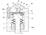
ステータがハウジングに一体化された流路切換バルブに本発明を適用した実施例について図4を用いて説明する。 An embodiment in which the present invention is applied to a flow path switching valve in which a stator is integrated with a housing will be described with reference to FIG.
ハウジング40は、図1から図3を用いて説明した実施例と同様に、ハウジングボディ40aとハウジングトップ40bによって構成され、ハウジングトップ40bがハウジングボディ40aの上におかれてボルト48によって固定されている。接続ポート42や44はハウジングトップ40bに設けられ、接続ポート42,44に通じる流路43,45の端部がハウジング40の内壁面をなすハウジングトップ40bの下面中央部46に達している。ハウジングトップ40bの下面中央部46はロータ8との摺動面(ポート端部配置面)をなしており、ロータ8と摺動するステータがハウジングトップ40bに一体化されている。
The
ロータ駆動軸6の基端部はハウジングボディ40bの底部に設けられた穴41を通ってハウジング40の外部に引き出され、ハウジング40の外部のモータ等の回転機構(図示は省略)によってその軸芯を中心に回転させられる。
The base end portion of the
ロータ駆動軸6によって回転させられるロータ8は、例えばステンレスやチタンなど耐薬品性を有する硬質部材で構成され、ステータ14側の面は耐薬品性及び摺動性の優れた樹脂膜30によって被膜されている。樹脂膜30は図1及び図3の実施例において説明した樹脂膜30と同じである。
The
ハウジングトップ40bの材質はステンレスやチタンなどの金属又はアルミナやジルコニアなどのセラミックスである。ハウジングトップ40bの下面中央部46はロータ8との摺動面であるため、その表面が例えばダイヤモンド砥粒(粒径1〜3μm)による研磨処理によって鏡面加工されていることが好ましい。さらに、鏡面加工したハウジングトップ40bの下面中央部46の表面に、例えば厚さが2μm程度のDLCコーティングを施すことで、ロータ8との摺動性をさらに高めることができる。
The material of the
なお、図5に示されているように、ハウジングトップ40bの下面が樹脂膜50によって被膜されていてもよい。樹脂膜50は、樹脂膜30と同様に、PEEK樹脂やポリイミド樹脂がハウジングトップ40bの下面に100μm程度の厚みでコーティングされたものである。この場合、ハウジングトップ40bは例えばステンレスやチタンなどで構成されている。ハウジングトップ40bの下面に樹脂膜50をコーティングする際、ブラスト処理によってハウジングトップ40bの下面(ハウジングボディ40aとの接触部分を除く)に微細な凹凸を形成し、樹脂をコーティングした後でそのコーティングの表面に研磨処理を施して平坦度を10μm以下にすることが好ましい。
As shown in FIG. 5, the lower surface of the
図5の実施例において、ロータ8はステンレスやチタンなどの金属のほか、アルミナやジルコニアなどのセラミックス、PEEK樹脂、ポリイミド樹脂など耐薬品性を有する材料で構成されている。ロータ8がステンレスやチタンで構成されている場合には、ハウジングトップ40bとの摺動面の摺動性及び液密性を高めるために、その表面が例えばダイヤモンド砥粒(粒径1〜3μm)による研磨処理によって鏡面加工されていることが好ましい。さらに、鏡面加工したロータ8の表面に、例えば厚さが2μm程度のDLCコーティングを施すことで、ステータ14との摺動面の摺動性をさらに高めることができる。
In the embodiment of FIG. 5, the
また、図6に示されているように、ロータ8とハウジングトップ40bの互いの摺動面がそれぞれ樹脂膜30,50により被膜されていてもよい。この場合、ロータ8とハウジングトップ40bはともにステンレスやチタンなどで構成されている。
Further, as shown in FIG. 6, the sliding surfaces of the
2,40 ハウジング
2a,40a ハウジングボディ
2b,40b ハウジングトップ
3,41 ロータ駆動軸用の貫通穴
4,46 ハウジングトップの下面中央部(ポート端部配置面)
5,48 ボルト
6 ロータ駆動軸
6a ロータ保持部
7 バネ
8 ロータ
10 ロータ固定ピン
12 溝
14 ステータ
16 パッキン
20 ステータ固定ピン
22,24,42,44 接続ポート
23,25,43,45 流路
30,32,50 樹脂膜
34 窪み2,40
5, 48
Claims (5)
前記ハウジング内に設けられ、前記ハウジングの内壁面の一部をなし前記接続ポートへ通じる複数の穴が配置されているポート端部配置面を有するステータと、
前記ハウジング内に配置され、前記ステータの前記ポート端部配置面と液密を保って接し前記ポート端部配置面に配置されている前記穴の間を選択的に接続する溝が形成されている流路接続面を有するロータと、
前記ロータを回転させるロータ駆動部と、を備え、
前記ポート端部配置面と前記流路接続面の両方が耐薬品性及び摺動性を有する樹脂膜により被膜されている流路切換バルブ。 A housing having a plurality of connection ports for connecting the flow path pipe to the outer surface and having a space inside;
A stator having a port end arrangement surface provided in the housing, wherein a part of the inner wall surface of the housing is formed and a plurality of holes leading to the connection port are arranged;
A groove is formed in the housing and is in contact with the port end arrangement surface of the stator in a liquid-tight manner and selectively connects between the holes arranged in the port end arrangement surface. A rotor having a flow path connection surface;
A rotor drive unit for rotating the rotor,
A flow path switching valve in which both the port end portion arrangement surface and the flow path connection surface are coated with a resin film having chemical resistance and slidability.
Applications Claiming Priority (1)
| Application Number | Priority Date | Filing Date | Title |
|---|---|---|---|
| PCT/JP2013/056574 WO2014141358A1 (en) | 2013-03-11 | 2013-03-11 | Flow path switching valve |
Publications (2)
| Publication Number | Publication Date |
|---|---|
| JP5999252B2 true JP5999252B2 (en) | 2016-09-28 |
| JPWO2014141358A1 JPWO2014141358A1 (en) | 2017-02-16 |
Family
ID=51536061
Family Applications (1)
| Application Number | Title | Priority Date | Filing Date |
|---|---|---|---|
| JP2015505101A Expired - Fee Related JP5999252B2 (en) | 2013-03-11 | 2013-03-11 | Flow path switching valve |
Country Status (4)
| Country | Link |
|---|---|
| US (1) | US20160025690A1 (en) |
| JP (1) | JP5999252B2 (en) |
| CN (1) | CN105026810A (en) |
| WO (1) | WO2014141358A1 (en) |
Families Citing this family (7)
| Publication number | Priority date | Publication date | Assignee | Title |
|---|---|---|---|---|
| ITUA20161724A1 (en) * | 2016-03-16 | 2017-09-16 | Seko Spa | SELECTOR DEVICE |
| DE102017101629A1 (en) | 2017-01-27 | 2018-08-02 | Agilent Technologies, Inc. - A Delaware Corporation - | Fluid valve with gold-containing and / or platinum-containing coating |
| WO2019186690A1 (en) | 2018-03-27 | 2019-10-03 | 株式会社島津製作所 | Multiport valve for water quality analyzer |
| JP7075816B2 (en) * | 2018-05-23 | 2022-05-26 | 住友重機械工業株式会社 | Rotary valve of ultra-low temperature refrigerator and ultra-low temperature refrigerator |
| CN109237075A (en) * | 2018-09-29 | 2019-01-18 | 成都凯天电子股份有限公司 | Multipassage rotary switching valve |
| CN109406594B (en) * | 2018-11-16 | 2024-01-02 | 苏州赛谱仪器有限公司 | PH flow cell device capable of switching flow paths |
| US12320441B1 (en) * | 2021-02-08 | 2025-06-03 | Schivo Medical Limited | Centering electronic rotary valve |
Citations (6)
| Publication number | Priority date | Publication date | Assignee | Title |
|---|---|---|---|---|
| JPH06300156A (en) * | 1993-04-13 | 1994-10-28 | Toto Ltd | Faucet |
| JPH07285807A (en) * | 1994-04-13 | 1995-10-31 | Inax Corp | Water faucet fitment coated with antibacterial coating film |
| JPH08159304A (en) * | 1994-11-30 | 1996-06-21 | Kyocera Corp | Disc valve |
| WO2009101695A1 (en) * | 2008-02-14 | 2009-08-20 | Shimadzu Corporation | Flow channel switching valve |
| JP2012533041A (en) * | 2009-07-13 | 2012-12-20 | アイデックス・ヘルス・アンド・サイエンス・リミテッド ライアビリティ カンパニー | Rotating shear valve assembly with hard-on-hard seal surface |
| JP2013501219A (en) * | 2009-07-29 | 2013-01-10 | ウオーターズ・テクノロジーズ・コーポレイシヨン | Rotating shear injector valve with coated stator surface |
Family Cites Families (30)
| Publication number | Priority date | Publication date | Assignee | Title |
|---|---|---|---|---|
| US3297053A (en) * | 1963-12-30 | 1967-01-10 | Carle Instr Inc | Selector valve |
| US4444066A (en) * | 1981-06-29 | 1984-04-24 | Beckman Instruments, Inc. | High pressure sample injector valve |
| EP0086073B1 (en) * | 1982-02-04 | 1986-11-12 | Toray Industries, Inc. | Rotary valve |
| US4476731A (en) * | 1983-03-03 | 1984-10-16 | Scientific Systems, Inc. | Injection valve for liquid chromatographic column and system therefor |
| US4577515A (en) * | 1984-06-19 | 1986-03-25 | Tokyo Rika Kikai Co., Ltd. | Sampling valve for use in high-speed liquid chromatography |
| JPS63104678A (en) * | 1986-10-20 | 1988-05-10 | Asahi Kagaku Gosei Kk | Intermittent coater |
| US5127438A (en) * | 1990-04-19 | 1992-07-07 | Williams Richard T | Long lasting faucet having minimum wear |
| US5193581A (en) * | 1992-03-17 | 1993-03-16 | Nkk Corporation | Selector valve |
| TW286346B (en) * | 1993-04-05 | 1996-09-21 | Toto Ltd | |
| US6012487A (en) * | 1997-03-10 | 2000-01-11 | Brian A. Hauck | Prime purge injection valve or multi-route selections valve |
| US7075640B2 (en) * | 1997-10-01 | 2006-07-11 | Arcturus Bioscience, Inc. | Consumable for laser capture microdissection |
| IT1307654B1 (en) * | 1999-01-29 | 2001-11-14 | Angelo Serratto | SERVO OPERATED VALVE FOR AIR CONDITIONING SYSTEMS KNOWN AS 4 PIPE SYSTEMS |
| US6193213B1 (en) * | 1999-03-05 | 2001-02-27 | Valco Instruments Company, Inc. | Variable pressure loading system utilizing combined spring and fluid pressure |
| US6453946B2 (en) * | 2000-03-10 | 2002-09-24 | Rheodyne, Lp | Long lifetime fluid switching valve |
| JP3971898B2 (en) * | 2000-05-25 | 2007-09-05 | 株式会社日立製作所 | Throttle body |
| US6748975B2 (en) * | 2001-12-26 | 2004-06-15 | Micralyne Inc. | Microfluidic valve and method of manufacturing same |
| JP2003215118A (en) * | 2002-01-29 | 2003-07-30 | Shimadzu Corp | Automatic sampler for liquid chromatography |
| JP4119275B2 (en) * | 2003-02-18 | 2008-07-16 | 忠弘 大見 | Diaphragm valve for vacuum exhaust system |
| JP2005061396A (en) * | 2003-07-31 | 2005-03-10 | Denso Corp | Air control valve |
| JP4412963B2 (en) * | 2003-10-10 | 2010-02-10 | 旭有機材工業株式会社 | Plastic parts for valves |
| JP4764348B2 (en) * | 2003-11-10 | 2011-08-31 | ウオーターズ・テクノロジーズ・コーポレイシヨン | Device and method for controlling fluid flow in a conduit |
| EP1729884A1 (en) * | 2004-01-30 | 2006-12-13 | Corning Incorporated | Multiwell plate and method for making multiwell plate using a low cytotoxicity photocurable adhesive |
| DE502006006654D1 (en) * | 2005-09-14 | 2010-05-20 | Belimo Holding Ag | BALL VALVE |
| US7544293B2 (en) * | 2005-09-26 | 2009-06-09 | Semba Inc. | Valve and process for interrupted continuous flow chromatography |
| US8016264B2 (en) * | 2006-05-02 | 2011-09-13 | Teijin Pharma Limited | Rotary-valve and adsorption separation system |
| US9316324B2 (en) * | 2008-10-29 | 2016-04-19 | Agilent Technologies, Inc. | Shear valve with silicon carbide member |
| US8438910B2 (en) * | 2009-05-07 | 2013-05-14 | Agilent Technologies, Inc. | Shear valve with DLC comprising multi-layer coated member |
| WO2011001460A1 (en) * | 2009-06-29 | 2011-01-06 | 株式会社島津製作所 | Flow path switching valve |
| US8627851B2 (en) * | 2010-06-14 | 2014-01-14 | Idex Health & Science Llc | Rebuildable micro-fluidic valve assembly |
| CN103518092B (en) * | 2011-05-05 | 2015-11-25 | 沃特世科技公司 | There is the high-pressure liquid switching valve that variable pressure loads |
-
2013
- 2013-03-11 JP JP2015505101A patent/JP5999252B2/en not_active Expired - Fee Related
- 2013-03-11 WO PCT/JP2013/056574 patent/WO2014141358A1/en not_active Ceased
- 2013-03-11 CN CN201380074270.0A patent/CN105026810A/en active Pending
- 2013-03-11 US US14/774,456 patent/US20160025690A1/en not_active Abandoned
Patent Citations (6)
| Publication number | Priority date | Publication date | Assignee | Title |
|---|---|---|---|---|
| JPH06300156A (en) * | 1993-04-13 | 1994-10-28 | Toto Ltd | Faucet |
| JPH07285807A (en) * | 1994-04-13 | 1995-10-31 | Inax Corp | Water faucet fitment coated with antibacterial coating film |
| JPH08159304A (en) * | 1994-11-30 | 1996-06-21 | Kyocera Corp | Disc valve |
| WO2009101695A1 (en) * | 2008-02-14 | 2009-08-20 | Shimadzu Corporation | Flow channel switching valve |
| JP2012533041A (en) * | 2009-07-13 | 2012-12-20 | アイデックス・ヘルス・アンド・サイエンス・リミテッド ライアビリティ カンパニー | Rotating shear valve assembly with hard-on-hard seal surface |
| JP2013501219A (en) * | 2009-07-29 | 2013-01-10 | ウオーターズ・テクノロジーズ・コーポレイシヨン | Rotating shear injector valve with coated stator surface |
Also Published As
| Publication number | Publication date |
|---|---|
| CN105026810A (en) | 2015-11-04 |
| US20160025690A1 (en) | 2016-01-28 |
| WO2014141358A1 (en) | 2014-09-18 |
| JPWO2014141358A1 (en) | 2017-02-16 |
Similar Documents
| Publication | Publication Date | Title |
|---|---|---|
| JP5999252B2 (en) | Flow path switching valve | |
| US20100276617A1 (en) | Flow channel switching valve | |
| JP4952795B2 (en) | Flow path switching valve | |
| JP2008215494A (en) | Flow path switching valve | |
| EP2454505B1 (en) | Rotary shear valve assembly with hard-on-hard seal surfaces | |
| JP5865403B2 (en) | Flow path switching valve and liquid chromatograph apparatus using the valve | |
| CN108474487B (en) | switch valve | |
| US20130284959A1 (en) | High-pressure control valve for high-performance liquid chromatography | |
| JP5692417B2 (en) | Flow path switching valve | |
| US20160082439A1 (en) | Spring-less multi-position micro-fluidic valve assembly | |
| JP7655300B2 (en) | Multiport valve for water quality analyzer | |
| WO2013088487A1 (en) | Liquid feed pump and liquid chromatograph | |
| TW201243156A (en) | Stator seal assembly in uniaxial eccentric screw pump | |
| JP4983292B2 (en) | Flow path switching valve | |
| CN114466984B (en) | Flow path switching valve, flow path switching valve system, and liquid chromatograph | |
| CN112368496B (en) | Seal and seal, in particular for rotary ball valve joints | |
| JP4586002B2 (en) | mechanical seal | |
| JP6743910B2 (en) | Centrifugal flow field fractionation device | |
| WO2022130950A1 (en) | Flow path switching valve and liquid chromatograph | |
| JP2001141149A (en) | Rotary joint | |
| JP2002166362A (en) | Rotary joint and shaft seal member | |
| WO2020039521A1 (en) | Flow channel switching valve | |
| CN121229653A (en) | A valve device | |
| JP2016125457A (en) | Plunger pump | |
| JP2018066399A (en) | Sealing device |
Legal Events
| Date | Code | Title | Description |
|---|---|---|---|
| TRDD | Decision of grant or rejection written | ||
| A01 | Written decision to grant a patent or to grant a registration (utility model) |
Free format text: JAPANESE INTERMEDIATE CODE: A01 Effective date: 20160802 |
|
| A61 | First payment of annual fees (during grant procedure) |
Free format text: JAPANESE INTERMEDIATE CODE: A61 Effective date: 20160815 |
|
| R151 | Written notification of patent or utility model registration |
Ref document number: 5999252 Country of ref document: JP Free format text: JAPANESE INTERMEDIATE CODE: R151 |
|
| LAPS | Cancellation because of no payment of annual fees |