JP5923733B2 - Light source device and projection display device - Google Patents
Light source device and projection display device Download PDFInfo
- Publication number
- JP5923733B2 JP5923733B2 JP2011269797A JP2011269797A JP5923733B2 JP 5923733 B2 JP5923733 B2 JP 5923733B2 JP 2011269797 A JP2011269797 A JP 2011269797A JP 2011269797 A JP2011269797 A JP 2011269797A JP 5923733 B2 JP5923733 B2 JP 5923733B2
- Authority
- JP
- Japan
- Prior art keywords
- light
- light source
- mirror
- optical path
- emitted
- Prior art date
- Legal status (The legal status is an assumption and is not a legal conclusion. Google has not performed a legal analysis and makes no representation as to the accuracy of the status listed.)
- Active
Links
Images




Landscapes
- Projection Apparatus (AREA)
- Non-Portable Lighting Devices Or Systems Thereof (AREA)
Description
本発明は、励起光を出射する光源と、励起光に応じて所定色成分光を出射する発光体とを備える光源装置及び投写型映像表示装置に関する。 The present invention relates to a light source device and a projection display apparatus including a light source that emits excitation light and a light emitter that emits predetermined color component light according to the excitation light.
従来、光源と、光源から出射された光を変調する光変調素子と、光変調素子から出射された光を投写面上に投写する投写ユニットとを有する投写型映像表示装置が知られている。 2. Description of the Related Art Conventionally, there is known a projection display apparatus including a light source, a light modulation element that modulates light emitted from the light source, and a projection unit that projects light emitted from the light modulation element onto a projection surface.
ここで、光源から出射される光を励起光として、赤成分光、緑成分光、青成分光などの基準映像光を出射する発光体を有する投写型映像表示装置が提案されている(例えば、特許文献1)。具体的には、各色成分光を出射する複数種類の発光体がカラーホイールに設けられており、カラーホイールの回転によって、各色成分光が時分割で出射される。 Here, a projection display apparatus having a light emitter that emits reference image light such as red component light, green component light, and blue component light using light emitted from a light source as excitation light has been proposed (for example, Patent Document 1). Specifically, a plurality of types of light emitters that emit each color component light are provided in the color wheel, and each color component light is emitted in a time division manner by the rotation of the color wheel.
ところで、青成分光を励起光及び基準映像光として用いるケースが考えられる。このようなケースでは、赤成分光及び緑成分光については、青成分光を励起光として発光体から出射され、青成分光については、光源から出射される青成分光がそのまま利用される。 By the way, a case where blue component light is used as excitation light and reference image light is conceivable. In such a case, for the red component light and the green component light, the blue component light is emitted from the light emitter as excitation light, and for the blue component light, the blue component light emitted from the light source is used as it is.
従って、青成分光を励起光として用いる第1光路及び青成分光を基準映像光として用いる第2光路に、光源から出射される青成分光を分離したいというニーズが存在する。 Therefore, there is a need to separate the blue component light emitted from the light source into the first optical path using blue component light as excitation light and the second optical path using blue component light as reference image light.
そこで、本発明は、上述した課題を解決するためになされたものであり、光源から出射される所定色成分光を第1光路及び第2光路に分離することを可能とする光源装置及び投写型映像表示装置を提供することを目的とする。 Therefore, the present invention has been made to solve the above-described problem, and a light source device and a projection type that can separate predetermined color component light emitted from a light source into a first optical path and a second optical path. An object is to provide a video display device.
第1の特徴に係る光源装置は、所定色成分光を出射する光源(光源10B)と、前記光源から出射された前記所定色成分光の一部の領域の光を反射すると共に、他の領域の光を反射しないように配置した分離光学素子(例えば、ミラー321)と、前記分離光学素子で反射或いは、反射されないことにより前記所定色成分光が分離された光路上に設けられており、励起光に応じて基準映像光を出射する発光体(例えば、発光体G)と、前記分離光学素子により分離された光路を1つの光路に纏める合成光学素子(例えば、ミラー124)とを備える。
The light source device according to the first feature reflects a light source (
第1の特徴において、前記発光体が設けられた光路は、前記所定色成分光を励起光として用いる光路であり、他の光路は、前記所定色成分光を基準映像光として用いる光路であり、前記発光体が設けられた光路の前記所定色成分光の光量は、他の光路の前記所定色成分光の光量よりも大きい。 In the first feature, the optical path provided with the light emitter is an optical path using the predetermined color component light as excitation light, and the other optical path is an optical path using the predetermined color component light as reference image light, The amount of the predetermined color component light in the optical path provided with the light emitter is larger than the amount of the predetermined color component light in the other optical paths .
第2の特徴に係る投写型映像表示装置は、第1の特徴に係る光源装置と、前記1つの光路上に設けられており、前記合成光学素子から出射される光を変調する光変調素子と、前記光変調素子から出射される光を投写する投写ユニットとを備える。 A projection display apparatus according to a second feature includes a light source device according to the first feature, a light modulation element that is provided on the one optical path and modulates light emitted from the combining optical element, and A projection unit that projects light emitted from the light modulation element.
本発明によれば、光源から出射される所定色成分光を第1光路及び第2光路に分離することを可能とする光源装置及び投写型映像表示装置を提供することができる。 ADVANTAGE OF THE INVENTION According to this invention, the light source device and projection type video display apparatus which can isolate | separate the predetermined color component light radiate | emitted from a light source into a 1st optical path and a 2nd optical path can be provided.
以下において、本発明の実施形態に係る光源装置及び投写型映像表示装置について、図面を参照しながら説明する。なお、以下の図面の記載において、同一又は類似の部分には、同一又は類似の符号を付している。 Hereinafter, a light source device and a projection display apparatus according to an embodiment of the present invention will be described with reference to the drawings. In the following description of the drawings, the same or similar parts are denoted by the same or similar reference numerals.
ただし、図面は模式的なものであり、各寸法の比率などは現実のものとは異なることに留意すべきである。従って、具体的な寸法などは以下の説明を参酌して判断すべきである。また、図面相互間においても互いの寸法の関係や比率が異なる部分が含まれていることは勿論である。 However, it should be noted that the drawings are schematic and ratios of dimensions and the like are different from actual ones. Therefore, specific dimensions and the like should be determined in consideration of the following description. Moreover, it is a matter of course that portions having different dimensional relationships and ratios are included between the drawings.
[実施形態の概要]
実施形態に係る光源装置は、所定色成分光を出射する光源と、前記光源から出射される前記所定色成分光を、前記所定色成分光を励起光として用いる第1光路及び前記所定色成分光を基準映像光として用いる第2光路に分離する分離光学素子と、前記第1光路上に設けられており、前記励起光に応じて基準映像光を出射する発光体と、前記第1光路及び前記第2光路を1つの光路に纏める合成光学素子とを備える。前記第1光路に分離される前記所定色成分光の光量は、前記第2光路に分離される前記所定色成分光の光量よりも大きい。
[Outline of Embodiment]
The light source device according to the embodiment includes a light source that emits predetermined color component light, a first optical path that uses the predetermined color component light emitted from the light source as excitation light, and the predetermined color component light. Is separated into a second optical path that is used as reference image light, a light emitting body that is provided on the first optical path and emits reference image light in response to the excitation light, the first optical path, and the optical path And a synthetic optical element that combines the second optical path into one optical path. The light amount of the predetermined color component light separated into the first optical path is larger than the light amount of the predetermined color component light separated into the second optical path.
実施形態では、分離光学素子は、光源から出射される所定色成分光を第1光路及び第2光路に分離することによって、励起光及び基準映像光の双方として所定色成分光を利用するというニーズを満たすことができる。 In the embodiment, the separation optical element needs to use the predetermined color component light as both the excitation light and the reference image light by separating the predetermined color component light emitted from the light source into the first optical path and the second optical path. Can be met.
実施形態では、第1光路に分離される所定色成分光の光量は、第2光路に分離される所定色成分光の光量よりも大きい。このように、所定色成分光の光量のうち、大きな光量が必要な励起光として用いる光量の比率が高いため、所定色成分光を適切に分配することが可能である。 In the embodiment, the light amount of the predetermined color component light separated into the first optical path is larger than the light amount of the predetermined color component light separated into the second optical path. Thus, since the ratio of the amount of light used as excitation light that requires a large amount of light among the amount of light of the predetermined color component light is high, it is possible to appropriately distribute the predetermined color component light.
なお、励起光は、主として青成分光である。基準映像光は、映像を構成する光であり、例えば、赤成分光、緑成分光又は青成分光である。 The excitation light is mainly blue component light. The reference image light is light constituting an image, and is, for example, red component light, green component light, or blue component light.
[第1実施形態]
(投写型映像表示装置)
以下において、第1実施形態に係る投写型映像表示装置について、図面を参照しながら説明する。図1は、第1実施形態に係る投写型映像表示装置100を示す図である。なお、第1実施形態では、基準映像光として、赤成分光R、緑成分光G及び青成分光Bを用いるケースについて例示する。
[First Embodiment]
(Projection-type image display device)
Hereinafter, the projection display apparatus according to the first embodiment will be described with reference to the drawings. FIG. 1 is a diagram showing a
図1に示すように、第1に、投写型映像表示装置100は、光源ユニット10と、カラーホイール20と、ロッドインテグレータ30と、DMD40と、投写ユニット50とを有する。
As shown in FIG. 1, first, the
光源ユニット10は、例えば、LD(Laser Diode)やLED(Light Emitting Diode)などの複数の固体光源によって構成される。第1実施形態では、光源ユニット10として、光源10B及び光源10Rが設けられる。
The
光源10Bは、青成分光Bを励起光及び基準映像光として出射する。光源10Bは、例えば、LD(Laser Diode)やLED(Light Emitting Diode)などである。
The
光源10Rは、基準映像光として赤成分光Rを出射する。光源10Rは、例えば、LD(Laser Diode)やLED(Light Emitting Diode)などである。
The
カラーホイール20は、励起光(青成分光B)の光軸に沿って延びる回転軸20Xを中心として回転するように構成される。カラーホイール20は、励起光を反射する反射型回転体の一例である。
The
詳細には、カラーホイール20は、図2に示すように、回転面21と、緑領域22Gとを有する。回転面21は、反射膜によって構成される。緑領域22Gは、光源10Bから出射される励起光(青成分光B)に応じて緑成分光Gを発光する発光体Gを有する。発光体Gは、蛍光体或いは燐光体である。
Specifically, as shown in FIG. 2, the
ロッドインテグレータ30は、ガラスなどの透明部材によって構成される中実のロッドである。ロッドインテグレータ30は、光源ユニット10から出射される光を均一化する。なお、ロッドインテグレータ30は、内壁がミラー面によって構成される中空のロッドであってもよい。
The
DMD40は、光源ユニット10から出射される光を変調する。詳細には、DMD40は、複数の微小ミラーによって構成されており、複数の微小ミラーは可動式である。各微小ミラーは、基本的に1画素に相当する。DMD40は、各微小ミラーの角度を変更することによって、投写ユニット50側に光を反射するか否かを切り替える。
The DMD 40 modulates light emitted from the
第1実施形態では、DMD40として、DMD40R、DMD40G及びDMD40Bが設けられる。DMD40Rは、赤映像信号Rに基づいて赤成分光Rを変調する。DMD40Gは、緑映像信号Gに基づいて緑成分光Gを変調する。DMD40Bは、青映像信号Bに基づいて青成分光Bを変調する。
In the first embodiment,
投写ユニット50は、DMD40によって変調された映像光を投写面上に投写する。
The
第2に、投写型映像表示装置100は、必要なレンズ群及びミラー群を有する。レンズ群としては、レンズ111〜レンズ116が設けられており、ミラー群としては、ミラー121〜ミラー125が設けられる。
Secondly, the
レンズ111は、光源10Bから出射される光を集光するコンデンサレンズである。レンズ112及びレンズ113は、励起光(青成分光B)を発光体(発光体G)の発光面上に集光するコンデンサレンズである。レンズ114は、光源10B及び光源10Rのそれぞれから出射される光をロッドインテグレータ30の光入射面に集光する集光レンズである。レンズ115及びレンズ116は、ロッドインテグレータ30から出射される光を各DMD40上に略結像するリレーレンズである。
The
ミラー121は、光源10Bから出射される青成分光Bのうち、一部分を透過し、残り部分を反射するビームスプリッターである。
The
ミラー122は、ミラー121で反射される青成分光Bを反射する反射ミラーである。ミラー123は、赤成分光Rを透過して、青成分光Bを反射するダイクロイックミラーである。ミラー124は、青成分光B及び赤成分光Rを透過して、緑成分光Gを反射するダイクロイックミラーである。ミラー125は、各色成分光を反射する反射ミラーである。
The
第1実施形態において、ミラー121は、光源10Bから出射される青成分光Bを、青成分光Bを励起光として用いる第1光路及び青成分光Bを基準映像光として用いる第2光路に分離する分離光学素子の一例である。ミラー124は、第1光路及び第2光路を1つの光路に纏める合成光学素子の一例である。
In the first embodiment, the
第3に、投写型映像表示装置100は、必要なプリズム群を有する。プリズム群として、プリズム210、プリズム220、プリズム230、プリズム240及びプリズム250が設けられる。
Thirdly, the
プリズム210は、透光性部材によって構成されており、面211及び面212を有する。プリズム210(面211)とプリズム250(面251)との間にはエアギャップが設けられており、プリズム210に入射した光が面211に入射する角度(入射角)が全反射角よりも大きいため、プリズム210に入射した光は面211で反射される。一方で、プリズム210(面212)とプリズム220(面221)との間にはエアギャップが設けられるが、面211で反射された光が面212に入射する角度(入射角)が全反射角よりも小さいため、面211で反射された光は面212を透過する。
The
プリズム220は、透光性部材によって構成されており、面221及び面222を有する。プリズム210(面212)とプリズム220(面221)との間にはエアギャップが設けられており、面222で最初に反射された青成分光B及びDMD40Bから出射された青成分光Bが面221に入射する角度(入射角)が全反射角よりも大きいため、面222で最初に反射された青成分光B及びDMD40Bから出射された青成分光Bは面221で反射される。一方で、面221で反射された後に面222で2回目に反射された青成分光Bが面221に入射する角度(入射角)が全反射角よりも小さいため、面221で反射された後に面222で2回目に反射された青成分光Bは面221を透過する。
The
面222は、赤成分光R及び緑成分光Gを透過して、青成分光Bを反射するダイクロイックミラー面である。従って、面211で反射された光のうち、赤成分光R及び緑成分光Gは面222を透過し、青成分光Bは面222で反射される。面221で反射された青成分光Bは面222で反射される。
The
プリズム230は、透光性部材によって構成されており、面231及び面232を有する。プリズム220(面222)とプリズム230(面231)との間にはエアギャップが設けられており、面231を透過して面232で反射された赤成分光R及びDMD40Rから出射された赤成分光Rが再び面231に入射する角度(入射角)が全反射角よりも大きいため、面231を透過して面232で反射された赤成分光R及びDMD40Rから出射された赤成分光Rは面231で反射される。一方で、DMD40Rから出射されて面231で反射された後に面232で反射された赤成分光Rが再び面231に入射する角度(入射角)が全反射角よりも小さいため、DMD40Rから出射されて面231で反射された後に面232で反射された赤成分光Rは面231を透過する。
The
面232は、緑成分光Gを透過して、赤成分光Rを反射するダイクロイックミラー面である。従って、面231を透過した光のうち、緑成分光Gは面232を透過し、赤成分光Rは面232で反射される。面231で反射された赤成分光Rは面232で反射される。DMD40Gから出射された緑成分光Gは面232を透過する。
The
プリズム240は、透光性部材によって構成されており、面241を有する。面241は、緑成分光Gを透過するように構成されている。なお、DMD40Gへ入射する緑成分光G及びDMD40Gから出射された緑成分光Gは面241を透過する。
The
プリズム250は、透光性部材によって構成されており、面251を有する。
The
言い換えると、青成分光Bは、(1)面211で反射されて、(2)面222で反射されて、(3)面221で反射されて、(4)DMD40Bで反射されて、(5)面221で反射されて、(6)面222で反射されて、(7)面221、面251を透過する。これによって、青成分光Bは、DMD40Bで変調されて、投写ユニット50に導かれる。
In other words, the blue component light B is (1) reflected by the
赤成分光Rは、(1)面211で反射されて、(2)面212、面221、面222及び面231を透過した上で、面232で反射されて、(3)面231で反射されて、(4)DMD40Rで反射されて、(5)面231で反射されて、(6)面232で反射されて、(7)面231、面232、面221、面212、面211及び面251を透過する。これによって、赤成分光Rは、DMD40Rで変調されて、投写ユニット50に導かれる。
The red component light R is (1) reflected on the
緑成分光Gは、(1)面211で反射されて、(2)面212、面221、面222、面231、面232、面241を透過した上で、DMD40Gで反射されて、(3)面241、面232、面231、面222、面221、面212、面211及び面251を透過する。これによって、緑成分光Gは、DMD40Gで変調されて、投写ユニット50に導かれる。
The green component light G is (1) reflected by the
(光源装置)
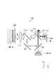
以下において、第1実施形態に係る光源装置について、図面を参照しながら説明する。図3は、第1実施形態に係る光源装置200を示す図である。
(Light source device)
The light source device according to the first embodiment will be described below with reference to the drawings. FIG. 3 is a diagram illustrating the
第1実施形態では、光源装置200は、主として、光源10B、光源10R及びカラーホイール20によって構成される。また、光源装置200は、必要なレンズ群及びミラー群を含む。
In the first embodiment, the
光源10Bは、図4に示すように、複数の発光素子11B及びヒートシンク12Bによって構成される。第1実施形態では、ヒートシンク12B上において、X軸方向に8つの発光素子11Bが並んでおり、Y軸方向に4つの発光素子11Bが並んでいる。
As shown in FIG. 4, the
ここで、光源10Bから出射される青成分光B(光源出射光)は、図5に示すように、ミラー121によって分割光X及び分割光Yに分離される。分割光Xは、第1光路に導かれる青成分光Bであり、励起光として用いられる。分割光Yは、第2光路に導かれる青成分光Bであり、基準映像光として用いられる。分割光Xの光量は、分割光Yの光量よりも大きい。
Here, the blue component light B (light source emission light) emitted from the
(作用及び効果)
第1実施形態では、ミラー121(分離光学素子)は、光源10Bから出射される青成分光Bを第1光路及び第2光路に分離することによって、励起光及び基準映像光の双方として所定色成分光を利用するというニーズを満たすことができる。
(Function and effect)
In the first embodiment, the mirror 121 (separation optical element) separates the blue component light B emitted from the
第1実施形態では、第1光路に分離される青成分光B(分割光X)の光量は、第2光路に分離される青成分光B(分割光Y)の光量よりも大きい。このように、青成分光Bの光量のうち、大きな光量が必要な励起光として用いる光量の比率が高いため、所定色成分光を適切に分配することが可能である。 In the first embodiment, the amount of blue component light B (divided light X) separated into the first optical path is larger than the amount of blue component light B (divided light Y) separated into the second optical path. Thus, since the ratio of the amount of light used as excitation light that requires a large amount of light among the amount of light of the blue component light B is high, it is possible to appropriately distribute the predetermined color component light.
[変更例1]
以下において、第1実施形態の変更例1について説明する。以下においては、第1実施形態に対する相違点について主として説明する。
[Modification 1]
Hereinafter, Modification Example 1 of the first embodiment will be described. In the following, differences from the first embodiment will be mainly described.
第1実施形態では、分離光学素子として、ミラー121(ビームスプリッター)が用いられる。これに対して、変更例1では、図6に示すように、分離光学素子として、ミラー121Aが用いられる。ミラー121Aは、ミラー121Aに入射する青成分光Bの偏光状態に応じて、所定方向(例えば、Y軸方向)の偏光成分を透過して、前記所定に直交する方向(例えば、Z軸方向)の偏光成分を反射する偏光分離素子である。
In the first embodiment, a mirror 121 (beam splitter) is used as the separation optical element. On the other hand, in the first modification, as shown in FIG. 6, a
ここで、光源10Bから出射される青成分光B(光源出射光)の偏光方向は、図7に示すように、ミラー121Aの透過軸方向(Y軸方向)に対して傾いている。すなわち、光源10Bを構成する発光素子11Bは、青成分光Bの偏光方向がミラー121Aの透過軸方向(Y軸方向)に対して傾くように配置される。
Here, as shown in FIG. 7, the polarization direction of the blue component light B (light source emission light) emitted from the
これによって、第1実施形態と同様に、光源10Bから出射される青成分光B(光源出射光)は、図7に示すように、ミラー121によって分割光X及び分割光Yに分離される。分割光Xは、第1光路に導かれる青成分光Bであり、励起光として用いられる。分割光Yは、第2光路に導かれる青成分光Bであり、基準映像光として用いられる。分割光Xの光量は、分割光Yの光量よりも大きい。
As a result, as in the first embodiment, the blue component light B (light source emitted light) emitted from the
[変更例2]
以下において、第1実施形態の変更例2について説明する。以下においては、第1実施形態に対する相違点について主として説明する。
[Modification 2]
Hereinafter, Modification Example 2 of the first embodiment will be described. In the following, differences from the first embodiment will be mainly described.
第1実施形態では、分離光学素子として、ミラー121(ビームスプリッター)が用いられる。これに対して、変更例2では、図8に示すように、分離光学素子として、ミラー121Aが用いられる。ミラー121Aは、ミラー121Aに入射する青成分光Bの偏光状態に応じて、所定方向(例えば、Y軸方向)の偏光成分を透過して、前記所定に直交する方向(例えば、Z軸方向)の偏光成分を反射する偏光分離素子である。
In the first embodiment, a mirror 121 (beam splitter) is used as the separation optical element. On the other hand, in the modified example 2, as shown in FIG. 8, a
ここで、光源装置200は、光源10Bから出射される青成分光Bの偏光方向を回旋する位相差板222を有する。位相差板222は、光源10Bから出射される青成分光Bの光路上において、光源10Bとミラー121Aとの間に設けられる。
Here, the
ここで、光源10Bから出射される青成分光B(光源出射光)の偏光方向は、図9の上段に示すように、ミラー121Aの透過軸方向(Y軸方向)に沿っている。これに対して、位相差板222から出射される青成分光B(位相差板出射光)の偏光方向は、図9の下段に示すように、ミラー121Aの透過軸方向(Y軸方向)に対して傾いている。
Here, the polarization direction of the blue component light B (light source emission light) emitted from the
これによって、変更例1と同様に、光源10Bから出射される青成分光B(光源出射光)は、ミラー121によって分割光X及び分割光Yに分離される。分割光Xは、第1光路に導かれる青成分光Bであり、励起光として用いられる。分割光Yは、第2光路に導かれる青成分光Bであり、基準映像光として用いられる。分割光Xの光量は、分割光Yの光量よりも大きい。
As a result, similarly to the first modification, the blue component light B (light source emission light) emitted from the
[変更例3]
以下において、第1実施形態の変更例3について説明する。以下においては、第1実施形態に対する相違点について主として説明する。
[Modification 3]
Hereinafter, Modification 3 of the first embodiment will be described. In the following, differences from the first embodiment will be mainly described.
第1実施形態では、分離光学素子として、ミラー121(ビームスプリッター)が用いられる。これに対して、変更例3では、図10に示すように、分離光学素子として、ミラー321が用いられる。ミラー321は、光源10Bから出射される青成分光B(光源出射光)の一部のみに設けられており、青成分光B(光源出射光)の一部のみを反射する。
In the first embodiment, a mirror 121 (beam splitter) is used as the separation optical element. On the other hand, in the modified example 3, as shown in FIG. 10, a
ここで、光源10Bから出射される青成分光B(光源出射光)の一部は、図11に示すように、ミラー321で反射される。
Here, a part of the blue component light B (light source emitted light) emitted from the
これによって、第1実施形態と同様に、光源10Bから出射される青成分光B(光源出射光)は、図11に示すように、ミラー321によって分割光X及び分割光Yに分離される。分割光Xは、第1光路に導かれる青成分光Bであり、励起光として用いられる。分割光Yは、第2光路に導かれる青成分光Bであり、基準映像光として用いられる。分割光Xの光量は、分割光Yの光量よりも大きい。
As a result, as in the first embodiment, the blue component light B (light source emission light) emitted from the
例えば、ミラー321は、図11に示すように、光源10Bを構成する発光素子11Bのうち、3×3の光源10Bを構成する発光素子11Bから出射される青成分光Bを反射する。
For example, as shown in FIG. 11, the
[変更例4]
以下において、第1実施形態の変更例4について説明する。以下においては、第1実施形態に対する相違点について主として説明する。
[Modification 4]
Hereinafter,
第1実施形態では、分離光学素子として、ミラー121(ビームスプリッター)が用いられる。これに対して、変更例4では、図12に示すように、分離光学素子として、ミラー421が用いられる。ミラー421は、所定波長の光を透過して、他の光を反射するダイクロイックミラーである。
In the first embodiment, a mirror 121 (beam splitter) is used as the separation optical element. On the other hand, in the modification example 4, as shown in FIG. 12, a
ここで、光源10Bは、図13に示すように、発光素子11B1及び発光素子11B2を有する。発光素子11B1は、ヒートシンク12B上において、領域Pに設けられる。発光素子11B2は、ヒートシンク12B上において、領域Qに設けられる。発光素子11B1から出射される光の波長帯は、発光素子11B2から出射される光の波長帯と異なる。ミラー421のカットオフ波長は、発光素子11B1から出射される光の波長帯と発光素子11B2から出射される光の波長帯との間に設けられる。
Here, the
これによって、第1実施形態と同様に、光源10Bから出射される青成分光B(光源出射光)は、図14に示すように、ミラー421によって分割光X及び分割光Yに分離される。分割光Xは、第1光路に導かれる青成分光B(例えば、発光素子11B1から出射される光)であり、励起光として用いられる。分割光Yは、第2光路に導かれる青成分光B(例えば、発光素子11B2から出射される光)であり、基準映像光として用いられる。分割光Xの光量は、分割光Yの光量よりも大きい。
As a result, as in the first embodiment, the blue component light B (light source emission light) emitted from the
[変更例5]
以下において、第1実施形態の変更例5について説明する。以下においては、第1実施形態に対する相違点について主として説明する。
[Modification 5]
Hereinafter, Modification 5 of the first embodiment will be described. In the following, differences from the first embodiment will be mainly described.
第1実施形態では、分離光学素子として、ミラー121(ビームスプリッター)が用いられる。これに対して、変更例5では、図15に示すように、分離光学素子として、ミラー521及びミラー522が設けられる。ミラー521及びミラー522は、光源10Bから出射される青成分光Bのうち、一部分を透過し、残り部分を反射するビームスプリッターである。
In the first embodiment, a mirror 121 (beam splitter) is used as the separation optical element. On the other hand, in the modified example 5, as shown in FIG. 15, a
また、カラーホイール20に代えて、カラーホイール20R及びカラーホイール20Gが設けられる。カラーホイール20Rは、光源10Bから出射される励起光(青成分光B)に応じて赤成分光Rを発光する発光体Rを有する反射型回転体である。カラーホイール20Gは、光源10Bから出射される励起光(青成分光B)に応じて緑成分光Gを発光する発光体Gを有する反射型回転体である。発光体R及び発光体Gは、蛍光体或いは燐光体である。
Further, instead of the
変更例5において、ミラー523及びミラー524は、ミラー522を透過する青成分光B(分割光Z)を反射する反射ミラーである。ミラー525は、青成分光B(分割光Y及び分割光Z)を透過して、緑成分光Gを反射するダイクロイックミラーである。ミラー526は、青成分光B(分割光X及び分割光Z)及び緑成分光Gを透過して、赤成分光Rを反射するダイクロイックミラーである。
In the fifth modification, the
変更例5では、光源10Bから出射される青成分光Bのうち、分割光X及び分割光Yは、励起光として用いられる。光源10Bから出射される青成分光Bのうち、分割光Zは、基準映像光として用いられる。
In the modification example 5, the split light X and the split light Y of the blue component light B emitted from the
[変更例6]
以下において、第1実施形態の変更例6について説明する。以下においては、変更例5に対する相違点について主として説明する。
[Modification 6]
Hereinafter, Modification Example 6 of the first embodiment will be described. In the following description, differences from Modification 5 will be mainly described.
変更例5では、カラーホイール20R及びカラーホイール20Gが用いられる。これに対して、変更例6では、図16に示すように、カラーホイール20R及びカラーホイール20Gに代えて、カラーホイール20RGが用いられる。
In the fifth modification, the
カラーホイール20RGは、図17に示すように、、回転面21と、赤領域22Rと、緑領域22Gとを有する。回転面21は、反射膜によって構成される。赤領域22Rは、光源10Bから出射される励起光(青成分光B)に応じて赤成分光Rを発光する発光体Rを有する。緑領域22Gは、光源10Bから出射される励起光(青成分光B)に応じて緑成分光Gを発光する発光体Gを有する。発光体Gは、蛍光体或いは燐光体である。発光体R及び発光体Gは、蛍光体或いは燐光体である。
As shown in FIG. 17, the color wheel 20RG has a
[変更例7]
以下において、第1実施形態の変更例7について説明する。以下においては、変更例6に対する相違点について主として説明する。
[Modification 7]
Hereinafter, Modification Example 7 of the first embodiment will be described. In the following description, differences from Modification 6 will be mainly described.
変更例6では、ミラー522は、ビームスプリッターであり、青成分光B(分割光Z)は、ミラー523及びミラー524で反射される。これに対して、変更例7では、図18に示すように、ミラー523及びミラー524が省略されて、青成分光Bを出射する光源10B2が設けられる。光源10B2は、例えば、LD(Laser Diode)やLED(Light Emitting Diode)などである。なお、ミラー522が全反射ミラーであることに留意すべきである。
In the sixth modification, the
変更例7すなわち、光源10Bから出射される青成分光B(分割光X及び分割光Y)は、いずれも励起光として用いられる。このように、第1光路及び第2光路は、いずれも、青成分光Bを励起光として用いる光路であってもよい。
Modification Example 7 That is, the blue component light B (split light X and split light Y) emitted from the
また、このようなケースにおいては、光源10Bから出射されるは、紫外成分光であってもよい。
In such a case, the light emitted from the
[変更例8]
以下において、第1実施形態の変更例8について説明する。以下においては、第1実施形態に対する相違点について主として説明する。
[Modification 8]
Hereinafter, Modification Example 8 of the first embodiment will be described. In the following, differences from the first embodiment will be mainly described.
第1実施形態では、分離光学素子として、ミラー121(ビームスプリッター)が用いられる。これに対して、変更例8では、図19及び図20に示すように、分離光学素子として、ミラー622が用いられる。ミラー622は、図21に示すように、ミラー622に入射する青成分光Bの偏光状態に応じて、ミラー622を透過する透過率及び反射率が異なる偏光分離素子である。なお、図21において、反射率は、(1−透過率)によって表される。
In the first embodiment, a mirror 121 (beam splitter) is used as the separation optical element. On the other hand, in the modified example 8, as shown in FIGS. 19 and 20, a
変更例8では、光源装置200は、ミラー622に加えて、ミラー621、ミラー623、ミラー624及びミラー625を有する。また、光源10Bは、ミラー622に入射する段階において、偏光状態が異なる青成分光Bを出射する複数の光源(光源10B1及び光源10B2)を含む。例えば、光源10B1は、ミラー621及びミラー622に対して、P偏光成分の青成分光Bを出射し、光源10B2は、ミラー621及びミラー622に対して、S偏光成分の青成分光Bを出射する。
In Modification Example 8, the
ミラー621は、光源10B1から出射される青成分光Bを透過して、光源10B2から出射される青成分光Bを反射するPBSミラーである。ミラー623は、ミラー622で反射された光を反射する反射ミラーである。ミラー624は、光源10Rから出射された赤成分光Rを透過して、ミラー623で反射された青成分光Bを反射するダイクロイックミラーである。ミラー625は、赤成分光R及び青成分光Bを透過して、緑成分光Gを反射するダイクロイックミラーである。
ここで、変更例8では、複数の光源10B(光源10B1及び光源10B2)のそれぞれから出射される青成分光Bの光量は、映像入力信号に応じて調整される。例えば、映像入力信号に基づいて、緑成分光Gの光量として大きな光量が必要であると判定された場合には、第1光路に導かれる分割光Xの光量を増大する。或いは、映像入力信号に基づいて、青成分光Bの光量として大きな光量が必要であると判定された場合には、第2光路に導かれる分割光Yの光量を増大する。
Here, in the modified example 8, the light amount of the blue component light B emitted from each of the plurality of
例えば、図19に示すように、100(指数)の光量を有する青成分光Bが光源10B1から出射され、100(指数)の光量を有する青成分光Bが光源10B2から出射される場合には、第1光路に導かれる分割光は、150(指数)の光量を有しており、第2光路に導かれる分割光は、50(指数)の光量を有する。
For example, as shown in FIG. 19, when the blue component light B having a light intensity of 100 (index) is emitted from the
これに対して、図20に示すように、150(指数)の光量を有する青成分光Bが光源10B1から出射され、50(指数)の光量を有する青成分光Bが光源10B2から出射される場合には、第1光路に導かれる分割光は、175(指数)の光量を有しており、第2光路に導かれる分割光は、25(指数)の光量を有する。
In contrast, as shown in FIG. 20, emitted blue component light B from the
[変更例9]
以下において、第1実施形態の変更例9について説明する。以下においては、変更例8に対する相違点について主として説明する。
[Modification 9]
Hereinafter, Modification 9 of the first embodiment will be described. In the following description, differences from Modification 8 will be mainly described.
変更例9では、光源10Bは、図22に示すように、複数の光源(光源1011、光源1012、光源1021及び光源1022)と、複数のミラー(反射ミラー13111、偏光ミラー13212、反射ミラー13121及び偏光ミラー13222)とを有する。
In the modification 9, the
光源1011、光源1012、光源1021及び光源1022は、ヒートシンク11と、複数の発光素子12とを有する。ヒートシンク11は、複数の発光素子12が生じる熱を放熱する金属板などである。各発光素子12は、青成分光Bを出射するLDやLEDなどである。
The
光源1012及び光源1022の光出射側には、1/2λ板15が設けられる。1/2λ板15は、光源1012及び光源1022から出射される青成分光Bの偏光方向を90°回転する位相差板である。
A 1 /
例えば、光源1012及び光源1022から出射される青成分光Bの偏光が偏光ミラー13212及び偏光ミラー13222に対してP偏光であるケースについて考える。このようなケースにおいて、1/2λ板15を透過する青成分光Bの偏光は、S偏光に変換される。
For example, the polarization of the blue component light B emitted from the light source 10 12 and the light source 10 22 considered case a P-polarized light with respect to the polarization mirror 132 12 and the polarization mirror 132 22. In such a case, the polarization of the blue component light B transmitted through the
反射ミラー13111は、光源1011からX軸方向に沿って出射される青成分光BをZ軸方向に反射するミラーである。同様に、反射ミラー13121は、光源1021からX軸方向に沿って出射される青成分光BをZ軸方向に反射するミラーである。
The
偏光ミラー13212及び偏光ミラー13222は、第1偏光成分(P偏光成分)を透過して、第2偏光成分(S偏光成分)を反射するミラーである。すなわち、偏光ミラー13212は、光源1012からX軸方向に沿って出射される青成分光BをZ軸方向に反射する。同様に、偏光ミラー13222は、光源1022からX軸方向に沿って出射される青成分光BをZ軸方向に反射する。なお、偏光ミラー13212は、反射ミラー13111で反射された青成分光Bを透過することに留意すべきである。同様に、偏光ミラー13222は、反射ミラー13121で反射された青成分光Bを透過することに留意すべきである。
The polarization mirror 132 12 and the polarization mirror 132 22 are mirrors that transmit the first polarization component (P polarization component) and reflect the second polarization component (S polarization component). That is, the polarizing mirror 132 12 reflects the blue component light B emitted from the
このように、反射ミラー13111、偏光ミラー13212、反射ミラー13121及び偏光ミラー13222は、光源1011、光源1012、光源1021及び光源1022から出射される光を合成する合成部130を構成する。
As described above, the
[その他の実施形態]
本発明は上述した実施形態によって説明したが、この開示の一部をなす論述及び図面は、この発明を限定するものであると理解すべきではない。この開示から当業者には様々な代替実施形態、実施例及び運用技術が明らかとなろう。
[Other Embodiments]
Although the present invention has been described with reference to the above-described embodiments, it should not be understood that the descriptions and drawings constituting a part of this disclosure limit the present invention. From this disclosure, various alternative embodiments, examples and operational techniques will be apparent to those skilled in the art.
実施形態では、光変調素子として、3つのDMDが例示されているが、実施形態は、これに限定されるものではない。光変調素子は、1つのDMDであってもよい。或いは、光変調素子は、1つの液晶パネル或いは3つの液晶パネル(赤液晶パネル、緑液晶パネル及び青液晶パネル)であってもよい。液晶パネルは、透過型であってもよく、反射型であってもよい。 In the embodiment, three DMDs are exemplified as the light modulation element, but the embodiment is not limited to this. The light modulation element may be one DMD. Alternatively, the light modulation element may be one liquid crystal panel or three liquid crystal panels (a red liquid crystal panel, a green liquid crystal panel, and a blue liquid crystal panel). The liquid crystal panel may be transmissive or reflective.
実施形態では、光源10Bは、偏光度の高い青成分光Bを出射する。しかしながら、実施形態は、これに限定されるものではない。例えば、偏光状態を1つの偏光(P偏光或いはS偏光)に揃える偏光変換素子が光源10Bの光出射側に設けられていれば、光源10Bから出射される青成分光Bの偏光度は低くてもよい。
In the embodiment, the
10…光源、20…カラーホイール、30…ロッドインテグレータ、40…DMD、50…投写ユニット、100…投写型映像表示装置、111〜116…レンズ、121〜125…ミラー、200…光源装置、221…ミラー、222…位相差板、321…ミラー、421…ミラー、521〜526…ミラー
DESCRIPTION OF
Claims (3)
前記光源から出射された前記所定色成分光の一部の領域の光を反射すると共に、他の領域の光を反射しないように配置した分離光学素子と、
前記分離光学素子で反射或いは、反射されないことにより前記所定色成分光が分離された光路上に設けられており、励起光に応じて基準映像光を出射する発光体と、
前記分離光学素子により分離された光路を1つの光路に纏める合成光学素子とを備えることを特徴とする光源装置。 A light source that emits predetermined color component light;
A separation optical element arranged so as to reflect the light of a part of the predetermined color component light emitted from the light source and not to reflect the light of another area;
A light emitting body that is provided on an optical path from which the predetermined color component light is separated by being reflected or not reflected by the separation optical element, and that emits reference video light in accordance with excitation light; and
A light source device comprising: a combining optical element that combines the optical paths separated by the separating optical element into one optical path.
他の光路は、前記所定色成分光を基準映像光として用いる光路であり、
前記発光体が設けられた光路の前記所定色成分光の光量は、他の光路の前記所定色成分光の光量よりも大きいことを特徴とする請求項1に記載の光源装置。 The optical path provided with the light emitter is an optical path using the predetermined color component light as excitation light,
The other optical path is an optical path that uses the predetermined color component light as reference image light,
2. The light source device according to claim 1, wherein a light amount of the predetermined color component light in an optical path provided with the light emitter is larger than a light amount of the predetermined color component light in another optical path.
前記1つの光路上に設けられており、前記合成光学素子から出射される光を変調する光変調素子と、A light modulation element that is provided on the one optical path and modulates light emitted from the synthesis optical element;
前記光変調素子から出射される光を投写する投写ユニットとを備えることを特徴とする投写型映像表示装置。A projection display apparatus comprising: a projection unit that projects light emitted from the light modulation element.
Priority Applications (1)
| Application Number | Priority Date | Filing Date | Title |
|---|---|---|---|
| JP2011269797A JP5923733B2 (en) | 2011-10-31 | 2011-12-09 | Light source device and projection display device |
Applications Claiming Priority (3)
| Application Number | Priority Date | Filing Date | Title |
|---|---|---|---|
| JP2011238986 | 2011-10-31 | ||
| JP2011238986 | 2011-10-31 | ||
| JP2011269797A JP5923733B2 (en) | 2011-10-31 | 2011-12-09 | Light source device and projection display device |
Publications (3)
| Publication Number | Publication Date |
|---|---|
| JP2013117705A JP2013117705A (en) | 2013-06-13 |
| JP2013117705A5 JP2013117705A5 (en) | 2014-11-27 |
| JP5923733B2 true JP5923733B2 (en) | 2016-05-25 |
Family
ID=48712285
Family Applications (1)
| Application Number | Title | Priority Date | Filing Date |
|---|---|---|---|
| JP2011269797A Active JP5923733B2 (en) | 2011-10-31 | 2011-12-09 | Light source device and projection display device |
Country Status (1)
| Country | Link |
|---|---|
| JP (1) | JP5923733B2 (en) |
Families Citing this family (8)
| Publication number | Priority date | Publication date | Assignee | Title |
|---|---|---|---|---|
| WO2015072039A1 (en) * | 2013-11-18 | 2015-05-21 | 日立マクセル株式会社 | Solid state light source device, automotive lighting using same, image display device, and drive method for solid state light source device |
| JP6107619B2 (en) * | 2013-11-27 | 2017-04-05 | 株式会社Jvcケンウッド | Light source device and projection device |
| CN106164770B (en) * | 2014-03-31 | 2017-10-03 | Nec显示器解决方案株式会社 | Light source and projecting apparatus |
| WO2015151171A1 (en) * | 2014-03-31 | 2015-10-08 | Necディスプレイソリューションズ株式会社 | Light source device and projector |
| JP6330147B2 (en) * | 2015-01-30 | 2018-05-30 | パナソニックIpマネジメント株式会社 | Light source device and projection display device |
| WO2016170966A1 (en) * | 2015-04-20 | 2016-10-27 | ソニー株式会社 | Light source device, projection display device, and display system |
| JP6390922B2 (en) | 2016-02-25 | 2018-09-19 | カシオ計算機株式会社 | Light source device and projection device |
| JP2023152298A (en) * | 2020-08-25 | 2023-10-17 | ソニーグループ株式会社 | Light source device and image display device |
Family Cites Families (9)
| Publication number | Priority date | Publication date | Assignee | Title |
|---|---|---|---|---|
| JP2006220762A (en) * | 2005-02-08 | 2006-08-24 | Victor Co Of Japan Ltd | Projection type image display device |
| JP2008293838A (en) * | 2007-05-25 | 2008-12-04 | Nikon Corp | Light source device |
| DE102008031996A1 (en) * | 2008-07-07 | 2010-02-18 | Osram Gesellschaft mit beschränkter Haftung | Radiation-emitting device |
| JP4924677B2 (en) * | 2009-08-21 | 2012-04-25 | カシオ計算機株式会社 | Light source device, projection device, and projection method |
| JP2011154930A (en) * | 2010-01-28 | 2011-08-11 | Seiko Epson Corp | Lighting device and projector |
| JP5573473B2 (en) * | 2010-08-06 | 2014-08-20 | セイコーエプソン株式会社 | Light source device and projector |
| JP5311155B2 (en) * | 2010-12-14 | 2013-10-09 | カシオ計算機株式会社 | Light source device and projector |
| JP2012141411A (en) * | 2010-12-28 | 2012-07-26 | Jvc Kenwood Corp | Light source device |
| JP5861348B2 (en) * | 2011-09-15 | 2016-02-16 | 株式会社リコー | Illumination optical system and projection device |
-
2011
- 2011-12-09 JP JP2011269797A patent/JP5923733B2/en active Active
Also Published As
| Publication number | Publication date |
|---|---|
| JP2013117705A (en) | 2013-06-13 |
Similar Documents
| Publication | Publication Date | Title |
|---|---|---|
| JP5558996B2 (en) | Light source device and projection display device | |
| JP5923733B2 (en) | Light source device and projection display device | |
| JP5914808B2 (en) | Light source device and projection display device | |
| JP5842167B2 (en) | Light source device and projection display device | |
| JP5474698B2 (en) | Light source device and projection display device | |
| JP5743240B2 (en) | Illumination optical system provided with phosphor, projector, and irradiation method | |
| JP5164421B2 (en) | Color separation / synthesis optical system and image projection apparatus using the same | |
| CN106164770B (en) | Light source and projecting apparatus | |
| JP2013114229A (en) | Light source device and projection video display apparatus | |
| JP6229972B2 (en) | Lighting device | |
| US9785040B2 (en) | Wavelength conversion element, light source device, and projector | |
| WO2011092841A1 (en) | Illumination optical system and projector using same | |
| JP6244558B2 (en) | Light source device and projection display device | |
| US20180149955A1 (en) | Illumination device and projector | |
| JP2013072888A (en) | Projection type image displaying apparatus | |
| JP6330147B2 (en) | Light source device and projection display device | |
| JP5991389B2 (en) | Lighting device and projector | |
| JP6284098B2 (en) | Lighting device | |
| KR101798158B1 (en) | Light source device and projector comprising the same | |
| JPWO2018025351A1 (en) | projector | |
| JP7131177B2 (en) | Light source device and projector | |
| WO2016147580A1 (en) | Projector | |
| JP2015108830A (en) | Illumination optical system including phosphor, projector, and irradiation method | |
| JP6273501B2 (en) | Projection display device | |
| KR20110132872A (en) | Projection system |
Legal Events
| Date | Code | Title | Description |
|---|---|---|---|
| A521 | Request for written amendment filed |
Free format text: JAPANESE INTERMEDIATE CODE: A523 Effective date: 20141009 |
|
| A621 | Written request for application examination |
Free format text: JAPANESE INTERMEDIATE CODE: A621 Effective date: 20141009 |
|
| A711 | Notification of change in applicant |
Free format text: JAPANESE INTERMEDIATE CODE: A711 Effective date: 20141107 |
|
| RD03 | Notification of appointment of power of attorney |
Free format text: JAPANESE INTERMEDIATE CODE: A7423 Effective date: 20141114 |
|
| A977 | Report on retrieval |
Free format text: JAPANESE INTERMEDIATE CODE: A971007 Effective date: 20150814 |
|
| A131 | Notification of reasons for refusal |
Free format text: JAPANESE INTERMEDIATE CODE: A131 Effective date: 20150818 |
|
| A521 | Request for written amendment filed |
Free format text: JAPANESE INTERMEDIATE CODE: A523 Effective date: 20151015 |
|
| TRDD | Decision of grant or rejection written | ||
| A01 | Written decision to grant a patent or to grant a registration (utility model) |
Free format text: JAPANESE INTERMEDIATE CODE: A01 Effective date: 20160209 |
|
| A61 | First payment of annual fees (during grant procedure) |
Free format text: JAPANESE INTERMEDIATE CODE: A61 Effective date: 20160309 |
|
| R151 | Written notification of patent or utility model registration |
Ref document number: 5923733 Country of ref document: JP Free format text: JAPANESE INTERMEDIATE CODE: R151 |
|
| S111 | Request for change of ownership or part of ownership |
Free format text: JAPANESE INTERMEDIATE CODE: R313113 |
|
| S531 | Written request for registration of change of domicile |
Free format text: JAPANESE INTERMEDIATE CODE: R313531 |
|
| SZ03 | Written request for cancellation of trust registration |
Free format text: JAPANESE INTERMEDIATE CODE: R313Z03 |
|
| R350 | Written notification of registration of transfer |
Free format text: JAPANESE INTERMEDIATE CODE: R350 |
|
| S111 | Request for change of ownership or part of ownership |
Free format text: JAPANESE INTERMEDIATE CODE: R313113 |
|
| R350 | Written notification of registration of transfer |
Free format text: JAPANESE INTERMEDIATE CODE: R350 |
|
| R250 | Receipt of annual fees |
Free format text: JAPANESE INTERMEDIATE CODE: R250 |