JP5852510B2 - Portable electronic devices - Google Patents
Portable electronic devices Download PDFInfo
- Publication number
- JP5852510B2 JP5852510B2 JP2012121997A JP2012121997A JP5852510B2 JP 5852510 B2 JP5852510 B2 JP 5852510B2 JP 2012121997 A JP2012121997 A JP 2012121997A JP 2012121997 A JP2012121997 A JP 2012121997A JP 5852510 B2 JP5852510 B2 JP 5852510B2
- Authority
- JP
- Japan
- Prior art keywords
- electronic device
- sound
- portable electronic
- unit
- user
- Prior art date
- Legal status (The legal status is an assumption and is not a legal conclusion. Google has not performed a legal analysis and makes no representation as to the accuracy of the status listed.)
- Expired - Fee Related
Links
Images


Classifications
-
- H—ELECTRICITY
- H04—ELECTRIC COMMUNICATION TECHNIQUE
- H04R—LOUDSPEAKERS, MICROPHONES, GRAMOPHONE PICK-UPS OR LIKE ACOUSTIC ELECTROMECHANICAL TRANSDUCERS; ELECTRIC HEARING AIDS; PUBLIC ADDRESS SYSTEMS
- H04R1/00—Details of transducers, loudspeakers or microphones
- H04R1/02—Casings; Cabinets ; Supports therefor; Mountings therein
-
- H—ELECTRICITY
- H04—ELECTRIC COMMUNICATION TECHNIQUE
- H04M—TELEPHONIC COMMUNICATION
- H04M1/00—Substation equipment, e.g. for use by subscribers
- H04M1/60—Substation equipment, e.g. for use by subscribers including speech amplifiers
- H04M1/6033—Substation equipment, e.g. for use by subscribers including speech amplifiers for providing handsfree use or a loudspeaker mode in telephone sets
- H04M1/6041—Portable telephones adapted for handsfree use
- H04M1/605—Portable telephones adapted for handsfree use involving control of the receiver volume to provide a dual operational mode at close or far distance from the user
-
- H—ELECTRICITY
- H04—ELECTRIC COMMUNICATION TECHNIQUE
- H04R—LOUDSPEAKERS, MICROPHONES, GRAMOPHONE PICK-UPS OR LIKE ACOUSTIC ELECTROMECHANICAL TRANSDUCERS; ELECTRIC HEARING AIDS; PUBLIC ADDRESS SYSTEMS
- H04R3/00—Circuits for transducers
- H04R3/12—Circuits for transducers for distributing signals to two or more loudspeakers
-
- H—ELECTRICITY
- H04—ELECTRIC COMMUNICATION TECHNIQUE
- H04M—TELEPHONIC COMMUNICATION
- H04M2250/00—Details of telephonic subscriber devices
- H04M2250/12—Details of telephonic subscriber devices including a sensor for measuring a physical value, e.g. temperature or motion
-
- H—ELECTRICITY
- H04—ELECTRIC COMMUNICATION TECHNIQUE
- H04R—LOUDSPEAKERS, MICROPHONES, GRAMOPHONE PICK-UPS OR LIKE ACOUSTIC ELECTROMECHANICAL TRANSDUCERS; ELECTRIC HEARING AIDS; PUBLIC ADDRESS SYSTEMS
- H04R2400/00—Loudspeakers
- H04R2400/03—Transducers capable of generating both sound as well as tactile vibration, e.g. as used in cellular phones
-
- H—ELECTRICITY
- H04—ELECTRIC COMMUNICATION TECHNIQUE
- H04R—LOUDSPEAKERS, MICROPHONES, GRAMOPHONE PICK-UPS OR LIKE ACOUSTIC ELECTROMECHANICAL TRANSDUCERS; ELECTRIC HEARING AIDS; PUBLIC ADDRESS SYSTEMS
- H04R2420/00—Details of connection covered by H04R, not provided for in its groups
- H04R2420/01—Input selection or mixing for amplifiers or loudspeakers
-
- H—ELECTRICITY
- H04—ELECTRIC COMMUNICATION TECHNIQUE
- H04R—LOUDSPEAKERS, MICROPHONES, GRAMOPHONE PICK-UPS OR LIKE ACOUSTIC ELECTROMECHANICAL TRANSDUCERS; ELECTRIC HEARING AIDS; PUBLIC ADDRESS SYSTEMS
- H04R2420/00—Details of connection covered by H04R, not provided for in its groups
- H04R2420/03—Connection circuits to selectively connect loudspeakers or headphones to amplifiers
-
- H—ELECTRICITY
- H04—ELECTRIC COMMUNICATION TECHNIQUE
- H04R—LOUDSPEAKERS, MICROPHONES, GRAMOPHONE PICK-UPS OR LIKE ACOUSTIC ELECTROMECHANICAL TRANSDUCERS; ELECTRIC HEARING AIDS; PUBLIC ADDRESS SYSTEMS
- H04R2430/00—Signal processing covered by H04R, not provided for in its groups
- H04R2430/01—Aspects of volume control, not necessarily automatic, in sound systems
-
- H—ELECTRICITY
- H04—ELECTRIC COMMUNICATION TECHNIQUE
- H04R—LOUDSPEAKERS, MICROPHONES, GRAMOPHONE PICK-UPS OR LIKE ACOUSTIC ELECTROMECHANICAL TRANSDUCERS; ELECTRIC HEARING AIDS; PUBLIC ADDRESS SYSTEMS
- H04R2440/00—Bending wave transducers covered by H04R, not provided for in its groups
- H04R2440/05—Aspects relating to the positioning and way or means of mounting of exciters to resonant bending wave panels
-
- H—ELECTRICITY
- H04—ELECTRIC COMMUNICATION TECHNIQUE
- H04R—LOUDSPEAKERS, MICROPHONES, GRAMOPHONE PICK-UPS OR LIKE ACOUSTIC ELECTROMECHANICAL TRANSDUCERS; ELECTRIC HEARING AIDS; PUBLIC ADDRESS SYSTEMS
- H04R2460/00—Details of hearing devices, i.e. of ear- or headphones covered by H04R1/10 or H04R5/033 but not provided for in any of their subgroups, or of hearing aids covered by H04R25/00 but not provided for in any of its subgroups
- H04R2460/13—Hearing devices using bone conduction transducers
-
- H—ELECTRICITY
- H04—ELECTRIC COMMUNICATION TECHNIQUE
- H04R—LOUDSPEAKERS, MICROPHONES, GRAMOPHONE PICK-UPS OR LIKE ACOUSTIC ELECTROMECHANICAL TRANSDUCERS; ELECTRIC HEARING AIDS; PUBLIC ADDRESS SYSTEMS
- H04R2499/00—Aspects covered by H04R or H04S not otherwise provided for in their subgroups
- H04R2499/10—General applications
- H04R2499/11—Transducers incorporated or for use in hand-held devices, e.g. mobile phones, PDA's, camera's
-
- H—ELECTRICITY
- H04—ELECTRIC COMMUNICATION TECHNIQUE
- H04R—LOUDSPEAKERS, MICROPHONES, GRAMOPHONE PICK-UPS OR LIKE ACOUSTIC ELECTROMECHANICAL TRANSDUCERS; ELECTRIC HEARING AIDS; PUBLIC ADDRESS SYSTEMS
- H04R3/00—Circuits for transducers
- H04R3/007—Protection circuits for transducers
-
- H—ELECTRICITY
- H04—ELECTRIC COMMUNICATION TECHNIQUE
- H04R—LOUDSPEAKERS, MICROPHONES, GRAMOPHONE PICK-UPS OR LIKE ACOUSTIC ELECTROMECHANICAL TRANSDUCERS; ELECTRIC HEARING AIDS; PUBLIC ADDRESS SYSTEMS
- H04R7/00—Diaphragms for electromechanical transducers; Cones
- H04R7/02—Diaphragms for electromechanical transducers; Cones characterised by the construction
- H04R7/04—Plane diaphragms
- H04R7/045—Plane diaphragms using the distributed mode principle, i.e. whereby the acoustic radiation is emanated from uniformly distributed free bending wave vibration induced in a stiff panel and not from pistonic motion
Landscapes
- Engineering & Computer Science (AREA)
- Signal Processing (AREA)
- Physics & Mathematics (AREA)
- Acoustics & Sound (AREA)
- Health & Medical Sciences (AREA)
- General Health & Medical Sciences (AREA)
- Otolaryngology (AREA)
- Telephone Function (AREA)
- Telephone Set Structure (AREA)
Description
本発明は、携帯型電子機器に関する。 The present invention relates to a portable electronic device.
従来から携帯型電子機器に関して様々な技術が提案されている。例えば特許文献1には、携帯型電子機器の一種である携帯電話機に関する技術が開示されている。 Conventionally, various technologies have been proposed for portable electronic devices. For example, Patent Document 1 discloses a technique related to a mobile phone that is a type of portable electronic device.
携帯電話機等の携帯型電子機器においては、外部スピーカから音が出力されたり、イヤホンあるいはヘッドホンに音を出力する外部出力部から音が出力されたりすることがある。例えば、携帯型電子機器が通信相手装置とテレビ電話通信を行っている際には、外部スピーカから音が出力されることがある。携帯型電子機器の使用者が、外部スピーカから出力される音を聞く際には、その外部スピーカの性能及び周囲の環境等によって音が聞きづらい場合がある。また、使用者が、外部出力部から出力される音をイヤホンあるいはヘッドホンで聞く場合にも、イヤホンあるいはヘッドホンの性能及び周囲の環境等によって音が聞きづらいことがある。 In a portable electronic device such as a mobile phone, sound may be output from an external speaker, or sound may be output from an external output unit that outputs sound to an earphone or a headphone. For example, when a portable electronic device is performing videophone communication with a communication partner device, sound may be output from an external speaker. When a user of a portable electronic device listens to sound output from an external speaker, it may be difficult to hear the sound depending on the performance of the external speaker and the surrounding environment. In addition, when the user listens to the sound output from the external output unit with the earphone or the headphone, the sound may be difficult to hear depending on the performance of the earphone or the headphone or the surrounding environment.
そこで、本発明は上述の点に鑑みて成されたものであり、使用者が聞きづらかった音を簡単に聞き直すことが可能な技術を提供することを目的とする。 Therefore, the present invention has been made in view of the above-described points, and an object thereof is to provide a technique that allows a user to easily rehearse a sound that is difficult to hear.
上記課題を解決するため、本発明に係る携帯型電子機器は、レシーバと、前記レシーバとは別に設けられた音出力部と、前記レシーバ及び前記音出力部を制御する制御部とを備え、前記制御部は、前記音出力部に音を出力させる音出力処理を行っている際に、前記携帯型電子機器の使用者の耳が当該携帯型電子機器に近づいたこと及び接触したことの少なくとも一方を検出すると、当該音出力処理で当該音出力部に出力させた音を再生して前記レシーバに出力させる音再生処理を行う。 In order to solve the above problems, a portable electronic device according to the present invention includes a receiver, a sound output unit provided separately from the receiver, and a control unit that controls the receiver and the sound output unit, The control unit, when performing sound output processing for outputting sound to the sound output unit, at least one of the user's ear of the portable electronic device approaching and contacting the portable electronic device Is detected, the sound output process is performed to reproduce the sound output to the sound output unit and output the sound to the receiver.
また、本発明に係る携帯型電子機器の一態様では、前記制御部は、前記音出力処理を行っている際に、前記使用者の耳が前記携帯型電子機器に近づいたことを検出すると準備処理を行い、その後、当該耳が当該携帯型電子機器にさらに近づいたことあるいは接触したことを検出すると前記音再生処理を行う。 In one aspect of the portable electronic device according to the present invention, the control unit prepares when detecting that the user's ear has approached the portable electronic device while performing the sound output processing. The sound reproduction process is performed when it is detected that the ear has further approached or contacted the portable electronic device.
また、本発明に係る携帯型電子機器の一態様では、前記準備処理には、前記制御部が前記音出力部の音量を小さくする処理、あるいは前記音出力部の音出力を停止する処理が含まれる。 In the aspect of the portable electronic device according to the present invention, the preparation process includes a process in which the control unit reduces the volume of the sound output unit or a process of stopping the sound output of the sound output unit. It is.
また、本発明に係る携帯型電子機器の一態様では、表示部が設けられ、前記準備処理には、前記制御部が前記表示部の表示をオフにする処理が含まれる。 In one aspect of the portable electronic device according to the present invention, a display unit is provided, and the preparation process includes a process in which the control unit turns off the display of the display unit.
また、本発明に係る携帯型電子機器の一態様では、音入力部と、通信相手装置と通信を行う通信部とがさらに設けられ、前記制御部が前記音出力部、前記音入力部及び前記通信部を制御することによって前記携帯型電子機器は通信相手装置との間で通話を行い、前記音出力処理は、前記携帯型電子機器が通話を行っている際の前記制御部が前記音出力部に音を出力させる処理であって、前記準備処理には、前記制御部が前記通信部を使用して通信相手装置に対して前記音再生処理の実行を通知する処理及び前記制御部が前記音入力部の機能をオフする処理の少なくとも一方が含まれる。 Moreover, in one aspect of the portable electronic device according to the present invention, a sound input unit and a communication unit that communicates with a communication partner device are further provided, and the control unit includes the sound output unit, the sound input unit, and the The portable electronic device makes a call with a communication partner device by controlling a communication unit, and the sound output processing is performed by the control unit when the portable electronic device is making a call. A process of causing the control unit to output a sound, wherein the control unit uses the communication unit to notify the communication partner device of the execution of the sound reproduction process and the control unit At least one of the processes for turning off the function of the sound input unit is included.
また、本発明に係る携帯型電子機器の一態様では、加速度センサがさらに設けられ、前記制御部は、前記加速度センサの出力信号に基づいて前記使用者の耳が前記携帯型電子機器に近づいたことを検出する。 In one aspect of the portable electronic device according to the present invention, an acceleration sensor is further provided, and the control unit has the user's ear approaching the portable electronic device based on an output signal of the acceleration sensor. Detect that.
また、本発明に係る携帯型電子機器の一態様では、近接センサがさらに設けられ、前記制御部は、前記近接センサの出力信号に基づいて前記使用者の耳が前記携帯型電子機器に近づいたことを検出する。 Further, in one aspect of the portable electronic device according to the present invention, a proximity sensor is further provided, and the control unit is configured such that the user's ear approaches the portable electronic device based on an output signal of the proximity sensor. Detect that.
また、本発明に係る携帯型電子機器の一態様では、撮像部がさらに設けられ、前記制御部は、前記音出力処理を行っている際に前記撮像部において前記使用者の耳が撮像されると、当該耳が前記携帯型電子機器に近づいたと判断する。 In one aspect of the portable electronic device according to the present invention, an imaging unit is further provided, and the control unit images the user's ear in the imaging unit while performing the sound output processing. Then, it is determined that the ear has approached the portable electronic device.
また、本発明に係る携帯型電子機器の一態様では、前記携帯型電子機器への物体の接触を検出するタッチパネルがさらに設けられ、前記制御部は、前記タッチパネルの出力信号に基づいて前記使用者の耳が前記携帯型電子機器に接触したことを検出する。 Moreover, in one aspect of the portable electronic device according to the present invention, a touch panel for detecting contact of an object with the portable electronic device is further provided, and the control unit is configured to output the user based on an output signal of the touch panel. It is detected that the ear of the user touches the portable electronic device.
また、本発明に係る携帯型電子機器の一態様では、撮像部と、表示部と、音入力部と、通信相手装置と通信を行う通信部とがさらに設けられ、前記制御部が前記撮像部、前記表示部、前記音出力部、前記音入力部及び前記通信部を制御することによって前記携帯型電子機器は通信相手装置との間でテレビ電話通信を行い、前記音出力処理は、前記携帯型電子機器がテレビ電話通信を行っている際の前記制御部が前記音出力部に音を出力させる処理であって、前記制御部は、前記携帯型電子機器がテレビ電話通信を行っている際に前記撮像部において前記使用者の顔が撮像されなくなると、当該使用者の耳が前記携帯型電子機器に近づいたと判断する。 Moreover, in one aspect of the portable electronic device according to the present invention, an imaging unit, a display unit, a sound input unit, and a communication unit that communicates with a communication partner device are further provided, and the control unit is the imaging unit. The portable electronic device performs videophone communication with a communication partner device by controlling the display unit, the sound output unit, the sound input unit, and the communication unit. Is a process in which the control unit outputs a sound to the sound output unit when the electronic device performs videophone communication, and the control unit performs the videophone communication when the portable electronic device performs videophone communication. When the user's face is no longer imaged by the imaging unit, it is determined that the user's ear has approached the portable electronic device.
また、本発明に係る携帯型電子機器の一態様では、前記制御部は、前記音再生処理において、前記使用者の耳が前記携帯型電子機器に近い状態あるいは接触した状態で音の再生が終了した際には、前記音出力処理で出力する音を前記レシーバに出力させ、その後、前記使用者の耳が前記携帯型電子機器から離れることを検出すると、前記レシーバに音を出力させないようにする。 Further, in one aspect of the portable electronic device according to the present invention, the control unit finishes reproducing the sound when the user's ear is close to or in contact with the portable electronic device in the sound reproduction process. In this case, the sound output in the sound output process is output to the receiver, and then, when it is detected that the user's ear is separated from the portable electronic device, the sound is not output to the receiver. .
また、本発明に係る携帯型電子機器の一態様では、前記制御部は、前記音出力処理を行っている際に、前記携帯型電子機器の使用者の耳が当該携帯型電子機器に近づいたこと及び接触したことの少なくとも一方を検出すると、前記音再生処理を行うとともに、前記音出力部の音量を小さくするかあるいは当該音出力部の音出力を中断し、前記制御部は、前記使用者の耳が前記携帯型電子機器から離れることを検出すると、前記レシーバに音を出力させないようにするとともに、前記音出力部の音量を元に戻すかあるいは当該音出力部の音出力を再開する。 Further, in one aspect of the portable electronic device according to the present invention, the control unit is close to the portable electronic device when the user of the portable electronic device is performing the sound output process. And at least one of the contact and the touch is detected, the sound reproduction process is performed, the volume of the sound output unit is reduced or the sound output of the sound output unit is interrupted, and the control unit When it is detected that the ear is away from the portable electronic device, the receiver is prevented from outputting sound, and the sound output unit is returned to the original volume or the sound output of the sound output unit is resumed.
また、本発明に係る携帯型電子機器の一態様では、表示部がさらに設けられ、前記制御部は、前記音出力処理を行っている際に、前記携帯型電子機器の使用者の耳が当該携帯型電子機器に近づいたこと及び接触したことの少なくとも一方を検出すると、前記音再生処理を行うとともに、前記表示部の表示をオフにし、前記制御部は、前記使用者の耳が前記携帯型電子機器から離れることを検出すると、前記レシーバに音を出力させないようにするとともに、前記表示部の表示をオンにする。 Further, in one aspect of the portable electronic device according to the present invention, a display unit is further provided, and the control unit is configured so that the ear of the user of the portable electronic device is in the sound output process. When at least one of approaching and contacting with a portable electronic device is detected, the sound reproduction process is performed and the display of the display unit is turned off, and the control unit is configured so that the user's ear is the portable type. When it is detected that the user is away from the electronic device, the receiver is prevented from outputting sound and the display of the display unit is turned on.
また、本発明に係る携帯型電子機器の一態様では、前記制御部は、前記音出力処理において前記携帯型電子機器に入力される音をリアルタイムに前記音出力部に出力させる場合には当該音を録音し、前記音再生処理において録音した当該音を再生して前記レシーバに出力させ、前記音出力処理において記憶済みの音を再生して前記音出力部に出力させる場合には、前記音再生処理において当該記憶済みの音を巻き戻して再生する。 Further, in one aspect of the portable electronic device according to the present invention, the control unit causes the sound output unit to output the sound input to the portable electronic device in real time in the sound output process. When the sound recorded in the sound reproduction process is reproduced and output to the receiver, and the stored sound is reproduced and output to the sound output unit in the sound output process, the sound reproduction is performed. In the processing, the stored sound is rewound and reproduced.
また、本発明に係る携帯型電子機器の一態様では、前記レシーバは、前記携帯型電子機器の前面に設けられたカバーパネルと、前記カバーパネルの内側主面上に設けられ、前記制御部によって音信号に基づいて振動される圧電振動素子とを有する。 Further, in one aspect of the portable electronic device according to the present invention, the receiver is provided on a front panel of the portable electronic device and an inner main surface of the cover panel, and is controlled by the control unit. A piezoelectric vibration element that is vibrated based on a sound signal.
また、本発明に係る携帯型電子機器の一態様では、前記音出力部はイヤホンあるいはヘッドホンに音を出力する外部出力部であって、前記音再生処理において、前記制御部は、前記音出力処理で前記外部出力部に出力させた音を再生して前記レシーバ及び前記外部出力部の両方に出力させる。 Further, in one aspect of the portable electronic device according to the present invention, the sound output unit is an external output unit that outputs sound to an earphone or a headphone, and in the sound reproduction process, the control unit includes the sound output process. The sound output to the external output unit is reproduced and output to both the receiver and the external output unit.
また、本発明に係る携帯型電子機器の一態様では、前記圧電振動素子が前記カバーパネルを振動させることによって、当該カバーパネルから気導音及び伝導音が前記使用者に伝達される。 In one aspect of the portable electronic device according to the present invention, the piezoelectric vibration element vibrates the cover panel, whereby air conduction sound and conduction sound are transmitted from the cover panel to the user.
本発明によれば、使用者は聞きづらかった音を簡単に聞き直すことができる。 According to the present invention, it is possible for a user to easily rehearse a sound that is difficult to hear.
<携帯型電子機器の外観>
図1〜4は、それぞれ、実施の形態に係る携帯型電子機器1の外観を示す斜視図、前面図、裏面図及び側面図である。図4は、図2に示される携帯型電子機器1を紙面左側から見た際の当該携帯型電子機器1が示されている。本実施の形態に係る携帯型電子機器1は、例えば携帯電話機である。
<Appearance of portable electronic devices>
1 to 4 are a perspective view, a front view, a back view, and a side view, respectively, showing the appearance of the portable electronic device 1 according to the embodiment. FIG. 4 shows the portable electronic device 1 when the portable electronic device 1 shown in FIG. 2 is viewed from the left side of the drawing. The portable electronic device 1 according to the present embodiment is a mobile phone, for example.
図1〜4に示されるように、携帯型電子機器1は、カバーパネル2とケース部分3を備えており、カバーパネル2とケース部分3とが組み合わされることによって、平面視で略長方形の板状を成す機器ケース4が構成されている。
As shown in FIGS. 1 to 4, the portable electronic device 1 includes a
カバーパネル2は、平面視において略長方形を成しており、携帯型電子機器1の前面部分における、周縁部分以外の部分を構成している。カバーパネル2は、例えば、透明のガラスあるいは透明のアクリル樹脂で形成されている。ケース部分3は、携帯型電子機器1の前面部分の周縁部分、側面部分及び裏面部分を構成している。ケース部分3は、例えばポリカーボネート樹脂で形成されている。
The
カバーパネル2には、文字、記号、図形等の各種情報が表示される表示部分2aが設けられている。表示部分2aは例えば平面視で長方形を成している。カバーパネル2における、表示部分2aを取り囲む周縁部分2bは、例えばフィルム等が貼られることによって黒色となっており、情報が表示されない非表示部分となっている。カバーパネル2の内側主面には後述するタッチパネル130が貼り付けられており、使用者は、カバーパネル2の表示部分2aを指等で操作することによって、携帯型電子機器1に対して各種指示を与えることができる。
The
機器ケース4の内部には、複数の操作ボタン141を備える操作部140が設けられている。各操作ボタン141は、いわゆる「ハードキー」であって、その表面が、カバーパネル2の外側主面20の下側端部から露出している。カバーパネル2の下側端部には、複数の操作ボタン141を露出させるための穴があけられている。また、カバーパネル2の下側端部にはマイク穴30があけられている。カバーパネル2の外側主面20の上側端部からは、後述する前面側撮像部200が有する撮像レンズ200aが露出している。なお、本実施の形態に係る携帯型電子機器1では、「ハードキー」である三つの操作ボタン141が設けられているが、操作ボタン141の個数を適宜変更しても良いし、操作ボタン141を設けなくても良い。
An
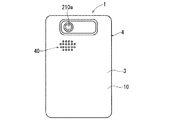
図2に示されるように、機器ケース4の内部には、後述する圧電振動素子221及び近接センサ150が設けられている。また、図3に示されるように、携帯型電子機器1の裏面10、言い換えれば機器ケース4の裏面には、スピーカ穴40があけられている。携帯型電子機器1の裏面10からは、後述する裏面側撮像部210が有する撮像レンズ210aが露出している。また、図4に示されるように、携帯型電子機器1をカバーパネル2側から見た際の当該携帯型電子機器1の左側側面11には外部端子50が設けられている。外部端子50にはイヤホンあるいはヘッドホンが有線で接続される。以後、イヤホン及びヘッドホンを総称して「音出力装置」と呼ぶことがある。
As shown in FIG. 2, a
<携帯型電子機器の電気的構成>
図5は携帯型電子機器1の電気的構成を主に示すブロック図である。図5に示されるように、携帯型電子機器1には、制御部100、無線通信部110、表示パネル120、タッチパネル130、操作部140、近接センサ150、加速度センサ160及び外部出力部170が設けられている。さらに携帯型電子機器1には、圧電振動素子221及びカバーパネル2で構成されたレシーバ220、外部スピーカ180、音入力部であるマイク190、前面側撮像部200、裏面側撮像部210及び電池230が設けられている。携帯型電子機器1に設けられた、カバーパネル2以外のこれらの構成要素は、機器ケース4内に収められている。
<Electrical configuration of portable electronic devices>
FIG. 5 is a block diagram mainly showing an electrical configuration of the portable electronic device 1. As shown in FIG. 5, the portable electronic device 1 includes a
制御部100は、CPU(Central Processing Unit)101、DSP(Digital Signal Processor)102及び記憶部103等を備えており、携帯型電子機器1の他の構成要素を制御することによって、携帯型電子機器1の動作を統括的に管理する。記憶部103は、ROM(Read Only Memory)及びRAM(Random Access Memory)等で構成されている。図6に示されるように、記憶部103には、携帯型電子機器1の動作、具体的には携帯型電子機器1が備える無線通信部110、表示パネル120等の各構成要素を制御するための制御プログラムであるメインプログラム104及び複数のアプリケーションプログラム105等が記憶されている。制御部100の各種機能は、CPU101及びDSP102が記憶部103内の各種プログラムを実行することによって実現される。
The
無線通信部110は、アンテナ111を有している。無線通信部110は、携帯型電子機器1とは別の携帯電話機あるいはインターネットに接続されたウェブサーバ等の通信装置からの信号を基地局を介してアンテナ111で受信する。無線通信部110は、受信信号に対して増幅処理及びダウンコンバートを行って制御部100に出力する。制御部100は、入力される受信信号に対して復調処理等を行って、当該受信信号に含まれる、音声や音楽などを示す音信号などを取得する。また無線通信部110は、制御部100で生成された、音信号等を含む送信信号に対してアップコンバート及び増幅処理を行って、処理後の送信信号をアンテナ111から無線送信する。アンテナ111からの送信信号は、基地局を通じて、携帯型電子機器1とは別の携帯電話機あるいはインターネットに接続された通信装置で受信される。
The
また、無線通信部110は、テレビ放送を受信するテレビアンテナ112を有しており、テレビアンテナ112で受信した受信信号を制御部100に出力する。制御部100は、入力されたテレビ放送の受信信号に含まれる動画像及び音声等を取得する。
In addition, the
表示パネル120は、例えば、液晶表示パネルあるいは有機ELパネルであって、制御部100によって制御されることによって、文字、記号、図形などの各種情報を表示する。表示パネル120に表示される情報は、カバーパネル2の表示部分2aに表示されることによって、当該情報は携帯型電子機器1の使用者に視認可能となる。
The
タッチパネル130は、例えば、投影型静電量容量方式のタッチパネルであって、カバーパネル2の表示部分2aに対する物体の接触を検出する。タッチパネル130は、カバーパネル2の内側主面に貼り付けられており、互いに対向配置されたシート状の二つの電極センサを備えている。二つの電極センサは透明粘着性シートによって貼り合わされている。
The
一方の電極センサには、それぞれがX軸方向(例えば携帯型電子機器1の左右方向)に沿って延在し、かつ互いに平行に配置された複数の細長いX電極が形成されている。他方の電極センサには、それぞれがY軸方向(例えば携帯型電子機器1の上下方向)に沿って延在し、かつ互いに平行に配置された複数の細長いY電極が形成されている。カバーパネル2の表示部分2aに対して使用者の指等が接触すると、その接触箇所の下にあるX電極及びY電極の間の静電容量が変化することによって、タッチパネル130においてカバーパネル2の表示部分2aに対する操作(接触)が検出される。タッチパネル130において生じる、X電極及びY電極の間の静電容量変化は制御部100に伝達され、制御部100は当該静電容量変化に基づいてカバーパネル2の表示部分2aに対して行われた操作の内容を特定し、それに応じた動作を行う。
One electrode sensor is formed with a plurality of elongated X electrodes that extend along the X-axis direction (for example, the left-right direction of the portable electronic device 1) and are arranged in parallel to each other. The other electrode sensor is formed with a plurality of elongated Y electrodes that extend along the Y-axis direction (for example, the vertical direction of the portable electronic device 1) and are arranged in parallel to each other. When a user's finger or the like comes into contact with the
操作部140は、複数の操作ボタン141のそれぞれについて、当該操作ボタン141が使用者によって押下されると、当該操作ボタン141が押下されたことを示す操作信号を制御部100に出力する。制御部100は、入力される操作信号に基づいて、複数の操作ボタン141のうちのどの操作ボタン141が操作されたかを特定し、操作された操作ボタン141に応じた動作を行う。
When the
近接センサ150は、例えば赤外線方式の近接センサであって、当該近接センサ150に対して物体が所定距離以内に近づくと検出信号を出力する。この検出信号は制御部100に入力される。携帯型電子機器1をカバーパネル2側(前面側)から見ると、図2に示されるように、近接センサ150は、カバーパネル2の上側端部の後ろ側に配置されている。これにより、カバーパネル2に対して人の頭等が近づくと、近接センサ150から検出信号が出力される。つまり、携帯型電子機器1の前面に物体が近づくと、近接センサ150から検出信号が出力される。
The
加速度センサ160は、例えば、3軸加速度センサであって、互いに直交する三つの検出軸のそれぞれについて、当該検出軸に沿った方向の加速度を検出して制御部100に出力する。
The
外部出力部170は、外部端子50に接続される音出力装置に音を出力する。具体的には、外部出力部170は、制御部100から出力される電気的な音信号を音出力装置に適した音信号に変換し、変換後の電気的な音信号を外部端子50に出力する。これにより、外部端子50に接続されたイヤホンあるいはヘッドホンから音が出力される。
The
外部スピーカ180は、例えばダイナミックスピーカであって、制御部100からの電気的な音信号を音に変換して出力する。外部スピーカ180から出力される音は、携帯型電子機器1の裏面10に設けられたスピーカ穴40から外部に出力される。スピーカ穴40から出力される音は、携帯型電子機器1から離れた場所でも聞こえるようになっている。
The
マイク190は、携帯型電子機器1の外部から入力される音を電気的な音信号に変換して制御部100に出力する。携帯型電子機器1の外部からの音は、カバーパネル2の前面に設けられたマイク穴30から携帯型電子機器1の内部に取り込まれてマイク190に入力される。なお、マイク穴30は、携帯型電子機器1の側面に設けても良いし、裏面10に設けても良い。
The
前面側撮像部200は、撮像レンズ200a及び撮像素子などで構成されており、制御部100による制御に基づいて、静止画像及び動画像を撮像する。図1,2に示されるように、撮像レンズ200aは、携帯型電子機器1の前面に設けられていることから、携帯型電子機器1の前面側(カバーパネル2側)に存在する物体を撮像することが可能である。
The front-
裏面側撮像部210は、撮像レンズ210a及び撮像素子などで構成されており、制御部100による制御に基づいて、静止画像及び動画像を撮像する。図3に示されるように、撮像レンズ210aは、携帯型電子機器1の裏面10に設けられていることから、携帯型電子機器1の裏面10側に存在する物体を撮像することが可能である。
The back
レシーバ220は、受話音を使用者に伝えるものであって、圧電振動素子221とカバーパネル2で構成されている。レシーバ220は、外部スピーカ180よりも小さい音量で音を出力する。レシーバ220は、使用者がカバーパネル2に耳を近づけたり接触させたりしたときに聞こえる程度の音を出力する。圧電振動素子221は、カバーパネル2の内側主面上に設けられており、制御部100から与えられる駆動電圧によって振動させられる。制御部100は、音信号に基づいて駆動電圧を生成し、当該駆動電圧を圧電振動素子221に与える。圧電振動素子221が、制御部100によって音信号に基づいて振動させられることによって、カバーパネル2が音信号に基づいて振動し、その結果、使用者に受話音が伝達される。レシーバ220については後で詳細に説明する。
The
電池230は、携帯型電子機器1の電源を出力する。電池230から出力された電源は、携帯型電子機器1が備える制御部100及び無線通信部110などに含まれる各電子部品に対して供給される。
The
記憶部103には様々なアプリケーションプログラム105(以後、単に「アプリケーション105」と呼ぶ)が記憶されている。記憶部103には、例えば、音声通話を行うための音声通話アプリケーション、通話の一種であるテレビ電話通信を行うためのテレビ電話アプリケーション、ウェブサイトを表示するためのブラウザ、電子メールの作成・閲覧・送受信を行うためのメールアプリケーション、記憶部103に記憶されている静止画像データを表示するためのアプリケーション、記憶部103に記憶されている音楽データを再生するための音楽再生アプリケーションが記憶されている。
The
また記憶部103には、記憶部103内に記憶されている、互いに関連づけられた音データ及び動画像データ(音付き動画像データ)を再生するための動画像再生アプリケーション(以後、「記憶動画像再生アプリケーション」と呼ぶ)、ウェブサイトからストリーミング方式あるいはプログレッシブダウンロード方式等によって配信される音付き動画像データを再生するための動画像再生アプリケーション(以後、「配信動画像再生アプリケーション」と呼ぶ)、アプリケーションを有料あるいは無料で提供するウェブサーバからアプリケーションをダウンロードするためのマーケットアプリケーション、携帯型電子機器1においてパズルゲーム等のゲームを行うためのゲームアプリケーション、テレビ放送を録画及び再生するためのテレビ視聴アプリケーションが記憶されている。記憶部103内の音付き動画像データとしては、テレビ放送のニュース番組及び英会話番組等を録画して得られる音付き動画像データ及びビデオカメラで撮像された動画像に係る音付き動画像データなどがある。
The
メインプログラム104を実行している制御部100が、記憶部103内のアプリケーション105を読み出して実行すると、制御部100は、無線通信部110、表示パネル120及びレシーバ220等の、携帯型電子機器1内の他の構成要素を制御し、それによって、当該アプリケーション105に対応する機能が携帯型電子機器1で実行される。
When the
例えば、音声通話アプリケーションを実行している制御部100は、音声の出力元がレシーバ220に設定されている場合には、無線通信部110、マイク190及びレシーバ220を制御する。これにより、携帯型電子機器1では、レシーバ220が使用されて通信相手装置との通話が行われる。また、音声通話アプリケーションを実行している制御部100は、音声の出力元が外部スピーカ180に設定されている場合には、無線通信部110、外部スピーカ180及びマイク190を制御する。これにより、携帯型電子機器1では、外部スピーカ180が使用されて通信相手装置との通話が行われる。また、音声通話アプリケーションを実行している制御部100は、音声の出力元が外部出力部170に設定されている場合には、無線通信部110、外部出力部170及びマイク190を制御する。これにより、携帯型電子機器1では、外部出力部170が使用されて通信相手装置との通話が行われる。
For example, the
また、テレビ電話アプリケーションを実行している制御部100は、音声の出力元が外部スピーカ180に設定されている場合には、無線通信部110、表示パネル120、外部スピーカ180、マイク190及び前面側撮像部200を制御する。これにより、携帯型電子機器1では外部スピーカ180が使用されて通信相手装置とのテレビ電話通信が行われる。
In addition, when the audio output source is set to the
また、テレビ電話アプリケーションを実行している制御部100は、音声の出力元が外部出力部170に設定されている場合には、無線通信部110、表示パネル120、外部出力部170、マイク190及び前面側撮像部200を制御する。これにより、携帯型電子機器1では外部出力部170が使用されて通信相手装置とのテレビ電話通信が行われる。
In addition, when the audio output source is set to the
また、記憶動画像再生アプリケーションを実行している制御部100は、音の出力元が外部スピーカ180に設定されている場合には、表示パネル120及び外部スピーカ180を制御する。これにより、携帯型電子機器1では、記憶部103内の音付き動画像データが再生される。
Further, the
また、配信動画像再生アプリケーションを実行している制御部100は、音の出力元が外部スピーカ180に設定されている場合には、無線通信部110、表示パネル120及び外部スピーカ180を制御する。これにより、携帯型電子機器1では、通信相手装置からストリーミング方式等で配信される音付き動画像データが再生される。
In addition, when the sound output source is set to the
<圧電振動素子の詳細>
図7,8は、それぞれ、圧電振動素子221の構造を示す上面図及び側面図である。図7,8に示されるように、圧電振動素子221は一方向に長い形状を成している。具体的には、圧電振動素子221は、平面視で長方形の細長い板状を成している。圧電振動素子221は、例えばバイモルフ構造を有しており、シム材221cを介して互いに貼り合わされた第1圧電セラミック板221a及び第2圧電セラミック板221bを備えている。
<Details of piezoelectric vibration element>
7 and 8 are a top view and a side view showing the structure of the
圧電振動素子221では、第1圧電セラミック板221aに対して正の電圧を印加し、第2圧電セラミック板221bに対して負の電圧を印加すると、第1圧電セラミック板221aは長手方向に沿って伸び、第2圧電セラミック板221bは長手方向に沿って縮むようになる。これにより、図9に示されるように、圧電振動素子221は、第1圧電セラミック板221aを外側にして山状に撓むようになる。
In the
一方で、圧電振動素子221では、第1圧電セラミック板221aに対して負の電圧を印加し、第2圧電セラミック板221bに対して正の電圧を印加すると、第1圧電セラミック板221aは長手方向に沿って縮み、第2圧電セラミック板221bは長手方向に沿って伸びるようになる。これにより、図10に示されるように、圧電振動素子221は、第2圧電セラミック板221bを外側にして山状に撓むようになる。
On the other hand, in the
圧電振動素子221は、図9の状態と図10の状態とを交互にとることによって、撓み振動を行う。制御部100は、第1圧電セラミック板221aと第2圧電セラミック板221bとの間に、正の電圧と負の電圧とが交互に現れる交流電圧を印加することによって、圧電振動素子221を撓み振動させる。
The
なお、図7〜10に示される圧電振動素子221では、シム材221cを間に挟んで貼り合わされた第1圧電セラミック板221a及び第2圧電セラミック板221bから成る構造が一つだけ設けられていたが、複数の当該構造を積層させても良い。
In addition, in the
<圧電振動素子の配置位置>
図11は携帯型電子機器1の上下方向(長手方向)における断面構造を示す図である。また図12は、カバーパネル2をその内側主面21側から見た際の平面図である。
<Arrangement position of piezoelectric vibration element>
FIG. 11 is a diagram showing a cross-sectional structure in the vertical direction (longitudinal direction) of the portable electronic device 1. FIG. 12 is a plan view of the
図11,12に示されるように、カバーパネル2の内側主面21には、当該カバーパネル2の表示部分2aと対向するようにタッチパネル130が貼り付けられている。そして、表示部である表示パネル120は、カバーパネル2及びタッチパネル130に対向するように配置されている。したがって、カバーパネル2と表示パネル120との間にはタッチパネル130が存在している。カバーパネル2では、表示パネル120と対向している部分が表示部分2aとなる。
As shown in FIGS. 11 and 12, a
また、機器ケース4の内部には、CPU101及びDSP102などの各種部品が搭載されるプリント基板250が設けられている。プリント基板250は、表示パネル120よりも携帯型電子機器1の裏面10側において当該表示パネル120と対向するように配置されている。また、図12に示されるように、カバーパネル2の下側端部には、複数の操作ボタン141をそれぞれ露出させる複数の穴22があけられている。
Inside the
圧電振動素子221は、両面テープ等の接着剤260によって、カバーパネル2の内側主面21に貼り付けられている。圧電振動素子221は、カバーパネル2の内側主面21上において、当該カバーパネル2を当該内側主面21側から見た平面視で表示パネル120及びタッチパネル130とは重ならない位置に配置されている。言い換えれば、圧電振動素子221は、カバーパネル2をその厚み方向において内側主面21側から見た際に、当該内側主面21上において、表示パネル120及びタッチパネル130とは重ならない位置に配置されている。したがって、カバーパネル2と圧電振動素子221との間には、タッチパネル130及び表示パネル120は存在していない。
The
また、圧電振動素子221は、カバーパネル2の内側主面21の上側端部21a上に設けられている。具体的には、圧電振動素子221は、図12に示されるように、カバーパネル2の内側主面21の上側端部21aにおける左右方向(長手方向に垂直な短手方向)の中央部21aa上に設けられている。
The
また、圧電振動素子221は、その長手方向がカバーパネル2の左右方向に一致するように配置されている。そして、圧電振動素子221は、その長手方向の中心が、カバーパネル2の内側主面21の上側端部21aにおける左右方向の中心と一致するように、当該上側端部21aの中央部21aaに配置されている。
Further, the
ここで、上述の図9,10に示されるように、撓み振動を行う圧電振動素子221では、その長手方向の中心が最も変位量が大きくなる。したがって、圧電振動素子221を、その長手方向の中心が、カバーパネル2の内側主面21の上側端部21aにおける左右方向の中心と一致するように、当該上側端部21aに配置することによって、圧電振動素子221における、撓み振動での変位量が最大となる箇所が、カバーパネル2の内側主面21の上側端部21aにおける左右方向の中心に一致するようになる。
Here, as shown in FIGS. 9 and 10 described above, in the
なお、タッチパネル130がカバーパネル2の内側主面21の全面に渡って存在する場合には、カバーパネル2の内側主面21上にタッチパネル130を介して圧電振動素子221を配置しても良い。
In the case where the
<レシーバによる受話音の発生について>
本実施の形態に係るレシーバ220では、圧電振動素子221がカバーパネル2を振動させることによって、当該カバーパネル2から気導音及び伝導音が使用者に伝達されるようになっている。言い換えれば、圧電振動素子221自身の振動がカバーパネル2に伝わることにより、当該カバーパネル2から気導音及び伝導音が使用者に伝達されるようになっている。
<Generation of received sound by receiver>
In the
ここで、気導音とは、外耳道孔(いわゆる「耳の穴」)に入った音波(空気振動)が鼓膜を振動させることによって、人の脳で認識される音である。一方で、伝導音とは、耳介が振動させられ、その耳介の振動が鼓膜に伝わって当該鼓膜が振動することによって、人の脳で認識される音である。以下に、気導音及び伝導音について詳細に説明する。 Here, the air conduction sound is a sound that is recognized by the human brain by sound waves (air vibration) entering the ear canal hole (so-called “ear hole”) vibrating the eardrum. On the other hand, the conduction sound is sound that is recognized by the human brain when the auricle is vibrated and the vibration of the auricle is transmitted to the eardrum and the eardrum vibrates. Hereinafter, the air conduction sound and the conduction sound will be described in detail.
図13は気導音及び伝導音を説明するための図である。図13には、携帯型電子機器1の使用者の耳の構造が示されている。図13においては、波線400は気道音が脳で認識される際の音信号(音情報)の伝導経路を示しており、実線410が伝導音が脳で認識される際の音信号の伝導経路を示している。
FIG. 13 is a diagram for explaining air conduction sound and conduction sound. FIG. 13 shows the structure of the ear of the user of the portable electronic device 1. In FIG. 13, a
カバーパネル2に取り付けられた圧電振動素子221が、受話音を示す電気的な音信号に基づいて振動させられると、カバーパネル2が振動して、当該カバーパネル2から音波が出力される。使用者が、携帯型電子機器1を手に持って、当該携帯型電子機器1のカバーパネル2を当該使用者の耳介300に近づけると、あるいは当該携帯型電子機器1のカバーパネル2を当該使用者の耳介300に当てると(接触させると)、当該カバーパネル2から出力される音波が外耳道孔310に入る。カバーパネル2からの音波は、外耳道孔310内を進み、鼓膜320を振動させる。鼓膜320の振動は耳小骨330に伝わり、耳小骨330が振動する。そして、耳小骨330の振動は蝸牛340に伝わって、蝸牛340において電気信号に変換される。この電気信号は、聴神経350を通って脳に伝達され、脳において受話音が認識される。このようにして、カバーパネル2から使用者に対して気導音が伝達される。
When the
また、使用者が、携帯型電子機器1を手に持って、当該携帯型電子機器1のカバーパネル2を当該使用者の耳介300に当てると、耳介300が、圧電振動素子221によって振動させられているカバーパネル2によって振動させられる。耳介300の振動は鼓膜320に伝わり、鼓膜320が振動する。鼓膜320の振動は耳小骨330に伝わり、耳小骨330が振動する。そして、耳小骨330の振動は蝸牛340に伝わり、蝸牛340において電気信号に変換される。この電気信号は、聴神経350を通って脳に伝達され、脳において受話音が認識される。このようにして、カバーパネル2から使用者に対して伝導音が伝達される。図13では、耳介300内部の耳介軟骨300aも示されている。
Further, when the user holds the portable electronic device 1 in his hand and touches the
なお、ここでの伝導音は、骨導音(「骨伝導音」とも呼ばれる)とは異なるものである。骨導音は、頭蓋骨を振動させて、頭蓋骨の振動が直接蝸牛などの内耳を刺激することによって、人の脳で認識される音である。図13においては、例えば下顎骨500を振動させた場合において、骨伝導音が脳で認識される際の音信号の伝達経路を複数の円弧420で示している。
The conduction sound here is different from the bone conduction sound (also referred to as “bone conduction sound”). Bone conduction sound is sound that is recognized by the human brain by vibrating the skull and directly stimulating the inner ear such as the cochlea. In FIG. 13, for example, when the
このように、本実施の形態に係る携帯型電子機器1では、圧電振動素子221が前面のカバーパネル2を適切に振動させることによって、カバーパネル2から携帯型電子機器1の使用者に対して気導音及び伝導音を伝えることができる。本実施の形態に係る圧電振動素子221では、使用者に対して適切に気導音及び伝導音を伝達できるように、その構造が工夫されている。使用者に対して気導音及び伝導音を伝えることができるように携帯型電子機器1を構成することによって様々メリットが発生する。
As described above, in the portable electronic device 1 according to the present embodiment, the
例えば、使用者は、カバーパネル2を耳に当てれば音が聞こえることから、携帯型電子機器1において耳を当てる位置をそれほど気にすることなく通話を行うことができる。
For example, since the user can hear a sound when the
また、使用者は、周囲の騒音が大きい場合には、耳をカバーパネル2に強く押し当てることによって、伝導音の音量を大きくしつつ、周囲の騒音を聞こえにくくすることができる。よって、使用者は、周囲の騒音が大きい場合であっても、適切に通話を行うことができる。
In addition, when the ambient noise is large, the user can make the surrounding noise difficult to hear while increasing the volume of the conduction sound by strongly pressing the ear against the
また、使用者は、耳栓やイヤホンを耳に取り付けた状態であっても、カバーパネル2を耳(より詳細には耳介)に当てることによって、携帯型電子機器1からの受話音を認識することができる。また、使用者は、耳にヘッドホンを取り付けた状態であっても、当該ヘッドホンにカバーパネル2を当てることによって、携帯型電子機器1からの受話音を認識することができる。
Further, the user recognizes the received sound from the portable electronic device 1 by placing the
なお、上記の例では、図11に示されるように、タッチパネル130と表示パネル120との間に隙間を設けているが、タッチパネル130と表示パネル120とを接触させても良い。本実施の形態のように、タッチパネル130と表示パネル120との間に隙間を設ける場合には、カバーパネル2が使用者によって指等で押されて、当該カバーパネル2が表示パネル120側に撓み、当該カバーパネル2が表示パネル120に当たって(より正確にはタッチパネル130が表示パネル120に当たって)当該表示パネル120の表示が乱れることを抑制することができる。
In the above example, as shown in FIG. 11, a gap is provided between the
以上のように、本実施の形態に係るレシーバ220は、外部スピーカ180で使用されるダイナミックスピーカ等で構成されているのではなく、音信号に基づいて振動される圧電振動素子221と、当該圧電振動素子221が搭載されたカバーパネル2とで構成されている。したがって、レシーバ220にダイナミックスピーカを用いる場合とは異なり、レシーバ用の穴(受話口の穴)をカバーパネル2に設ける必要はない。
As described above, the
<外部スピーカ及び外部出力部の出力音のレシーバでの再生処理について>
制御部100がアプリケーション105を実行している場合には、外部スピーカ180が使用されて当該外部スピーカ180から音が出力されることがある。
<Regarding playback processing of the output sound of the external speaker and the external output unit>
When the
例えば、制御部100は、音声通話アプリケーションを実行している場合において、音の出力元が外部スピーカ180に設定されている場合には、無線通信部110で受信された音声データに含まれる音声を外部スピーカ180に出力させる。
For example, when the voice communication application is executed and the sound output source is set to the
また、制御部100は、テレビ電話アプリケーションを実行している場合において、音の出力元が外部スピーカ180に設定されている場合には、無線通信部110で受信された音付き動画像データに含まれる動画像を表示パネル120に表示させるととともに、当該音付き動画像データに含まれる音声を外部スピーカ180に出力させる。
In addition, when the video phone application is executed and the sound output source is set to the
また、制御部100は、記憶動画像再生アプリケーションを実行している場合において、音の出力元が外部スピーカ180に設定されている場合には、記憶部103内の音付き動画像データに含まれる動画像を表示パネル120に表示させるとともに、当該音付き動画像データに含まれる音を外部スピーカ180に出力させる。
In addition, when the stored moving image playback application is executed and the sound output source is set to the
外部出力部170についても同様であって、制御部100がアプリケーション105を実行している場合には、外部出力部170が使用されて当該外部出力部170から音が出力されることがある。例えば、制御部100は、配信動画像再生アプリケーションを実行している場合において、音の出力元が外部出力部170に設定されている場合には、無線通信部110で受信される音付き動画像データに含まれる動画像を表示パネル120に表示させるとともに、当該音付き動画像データに含まれる音を外部出力部170に出力させる。以後、外部出力部170と外部スピーカ180を総称して「音出力部」と呼ぶことがある。
The same applies to the
携帯型電子機器1の使用者が、外部スピーカ180から出力される音を聞く際には、その外部スピーカ180の性能や周囲の環境によって音が聞きづらい場合がある。また、使用者が、外部出力部170から出力される音をイヤホン等の音出力装置で聞く場合にも、当該音出力装置の性能や周囲の環境によって音が聞きづらいことがある。録音された音(例えば英会話)が音出力部で再生されている場合には、使用者は、聞きづらかった音を再度再生して当該音出力部に出力させて、その音を聞き直すことが考えられる。このとき、聞き取りにくかった音を出力していた音出力部から再度同じ音を出力したとしても聞き取りにくい可能性が高い。さらに使用者は、携帯型電子機器1の表示部分2aを操作することによって、録音された音を巻き戻して再生する必要がある。
When the user of the portable electronic device 1 listens to the sound output from the
そこで、本実施の形態に係る携帯型電子機器1では、制御部100がアプリケーション105を実行している場合に音出力部から音を出力させている際に、携帯型電子機器1に対して使用者の耳が近づけられると、当該音出力部から出力された音が再生されてレシーバ220から出力されるようになっている。つまり、携帯型電子機器1では、制御部100は、音出力部から音を出力させる音出力処理を行っている際に、携帯型電子機器1に対して使用者の耳が近づいたことを検出すると、当該音出力部から出力された音を再生してレシーバ220に出力させる音再生処理を行うようになっている。これにより、使用者は、音出力部からの音が聞きづらかった場合には、自身の耳を携帯型電子機器1に近づけることによってあるいは接触させることによって、当該音出力部とは別に設けられたレシーバ220を使用して、その聞きづらかった音を聞き直すことができる。よって、使用者は、聞きづらかった音を簡単に聞き直すことができる。さらに、使用者は、聞きづらかった音出力部からの音を当該音出力部とは別に設けられたレシーバ220を使用して聞き直すことができることから、聞き直した際にその音が聞こえやすくなる可能性が高くなる。以下に、このレシーバ220での音再生処理について説明する。
Therefore, in the portable electronic device 1 according to the present embodiment, when the
図14は、テレビ電話アプリケーションが実行されているときにレシーバ220での音再生処理が行われる際の当該携帯型電子機器1の動作を示すフローチャートである。図14に示されるように、ステップs1において、制御部100は、使用者がカバーパネル2の表示部分2aを操作することによって携帯型電子機器1に対してテレビ電話アプリケーションの実行指示を行うと、記憶部103内からテレビ電話アプリケーションを読み出して実行する。これにより、携帯型電子機器1は、無線通信部110、表示パネル120、マイク190及び音出力部(外部スピーカ180あるいは外部出力部170)を使用して通信相手装置とテレビ電話通信を開始する。テレビ電話通信では、音出力部に音を出力させる音出力処理が行われる。
FIG. 14 is a flowchart showing the operation of the portable electronic device 1 when sound reproduction processing is performed by the
次にステップs2において、制御部100は、音出力部から出力される音(通信相手装置の使用者の音声)の録音を開始する。制御部100は、例えば、無線通信部110が受信する最新の一定時間(例えば30秒間)の音を上書きしながら録音し、録音した当該最新の一定時間の音を記憶部103に記憶する。したがって、テレビ電話通信が行われている間、記憶部103には常に、通信相手装置から受信した最新の音声(詳細には音声データ)が一定時間だけ保存されることになる。
Next, in step s2, the
音出力部から出力される音の録音が開始した後に、ステップs3において、制御部100が、図15に示されるように使用者600の耳610が携帯型電子機器1に近づいたことを検出すると、具体的には、使用者600の耳610が携帯型電子機器1のレシーバ220を構成するカバーパネル2に近づいたことを検出すると、ステップs4において、制御部100は、音出力部から出力された音を再生してレシーバ220に出力させる音再生処理を行う。以後、単に「音再生処理」と言えば、音出力部から出力された音を再生してレシーバ220に出力させる処理を意味する。テレビ電話通信において音出力部から出力されていた音を聞いていた使用者が、音出力部からの音が聞きづらかった場合には、その音をレシーバ220で聞き直すために、自身の耳を携帯型電子機器1に近づけようとする。そうすると、携帯型電子機器1ではステップs3,s4が順次実行される。なお、使用者の耳が携帯型電子機器1に近づいたことを検出する方法については後で詳細に説明する。
After the recording of the sound output from the sound output unit is started, in step s3, the
ステップs4においては、制御部100は、記憶部103内の録音された音を再生してレシーバ220に出力させる。このとき、録音された一定時間の音を最初から再生しても良いし、途中から再生しても良い。録音された音を途中から再生する場合には、当該録音された音において最近の無音時点を特定し、その無音時点から再生しても良い。これにより、音出力部から出力された音が再生されてレシーバ220のカバーパネル2から出力される。よって、カバーパネル2に耳を近づけているか接触させている使用者は、カバーパネル2からの再生音を聞くことによって、聞きづらかった音出力部からの音を聞き直すことができる。制御部100は、録音された音に係る音信号(音データ)に基づいて圧電振動素子221を駆動することによって、当該音を再生してカバーパネル2から出力させる。なお、ステップs4においては、録音された音を再生する際、倍速再生を行って再生時間を短縮してもよい。例えば、周囲の環境によって一時的に音が聞きづらかったが、再生する際にそれが解消されている場合などは、通信相手をできるだけ待たせないように、倍速再生を行って、再生時間を短縮してもよい。
In step s4, the
ステップs3が実行されると、制御部100は、ステップs4において、音再生処理以外にも、音再生処理を実行するにあたって行うことが望ましい付属処理を行う。本実施の形態では、付随処理として、制御部100は、表示パネル120のバックライトを消灯するなどして当該表示パネル120の表示をオフにする。また制御部100は、付随処理として、音出力部の機能をオフにする。つまり、制御部100は、音出力部の音出力を停止する。使用者は、レシーバ220のカバーパネル2に耳を近づけてあるいは接触させて、聞きづらかった音を聞き直すことから、表示パネル120の表示がオンとなっており、カバーパネル2の表示部分2aにテレビ電話通信の動画像が表示されていると、煩わしいと感じることがある。また、外部スピーカ180から音が出力されている状態で、使用者が耳をカバーパネル2に近づけていったときには、外部スピーカ180からの音を煩わしく感じたり、外部スピーカ180からの音によってカバーパネル2からの音が聞こえにくかったりすることがある。また、外部出力部170からの音がイヤホンから出力されている状態で、使用者がイヤホンを付けている耳とは逆の耳をカバーパネル2に近づけたり接触させたりする場合には、イヤホンからの音を煩わしく感じたり、イヤホンからの音によってカバーパネル2からの音が聞こえにくかったりすることがある。そこで、本実施の形態では、音再生処理の付随処理として、制御部100は、表示パネル120の表示をオフにするとともに、音出力部の音出力を停止している。これにより、携帯型電子機器1の消費電力が低減するといった効果も発生する。なお、音出力部の音出力を停止する代わりに、音出力部の音量を小さくしても良い。
When step s3 is executed, in step s4, the
また、制御部100は、付随処理として、無線通信部110を使用して、携帯型電子機器1がテレビ電話通信を行っている通信相手装置に対して音再生処理の実行の通知を行う。具体的には、制御部100は、音再生処理の実行の通知を行うための通知信号を生成して、この通知信号を、テレビ電話通信を行っている通信相手装置に向けて無線通信部110に送信させる。通信相手装置は、携帯型電子機器1から音再生処理の実行が通知されると、その旨を示す情報(以後、「音再生処理実行通知情報」と呼ぶ)を自装置の表示部に表示するなどして、当該通信相手装置の使用者に対して携帯型電子機器1での音再生処理の実行を通知する。通信相手装置の表示部には、音再生処理実行通知情報として、例えば「音の聞き直しを実行中」といった文字列が表示される。これにより、携帯型電子機器1とテレビ電話通信を行っている通信相手装置の使用者は、携帯型電子機器1の使用者が、音出力部から出力された音をレシーバ220で聞き直していることを認識することができる。その結果、通信相手装置の使用者が、携帯型電子機器1で音再生処理が行われている際に、当該通信相手装置と携帯型電子機器1との間の通信が異常になったと間違って認識することを抑制することができる。
In addition, as an accompanying process, the
また、制御部100は、付随処理として、マイク190の機能をオフにする。つまり、制御部100は、付属処理として、マイク190に入力される音を無効として、マイク190に入力される音がテレビ電話通信の通信相手装置に入力されないようにする。これにより、携帯型電子機器1の使用者がレシーバ220で音を聞き直している際に、不要な音が通信相手装置に入力されて、当該通信相手装置の使用者が不快な思いをすることを抑制することができる。また、制御部100は、マイク190の機能をオフするとともに、無線通信部110を使用して、音楽あるいは「しばらくお待ちください」といったアナウンスが通信相手装置に入力されるようにしてもよい。この場合には、通信相手装置は、入力された音楽あるいはアナウンスを外部スピーカ等を利用して当該通信相手装置の使用者に伝達する。
In addition, the
音再生処理及びその付随処理が実行された後、ステップs5において、録音された音のレシーバ220での再生が終了すると、言い換えれば、音出力部から出力された音についてのレシーバ220での再生が終了すると、ステップs6において、制御部100は、携帯型電子機器1が通常のテレビ電話通信を行うようにする。つまり、制御部100は、携帯型電子機器1の動作を、テレビ電話アプリケーションの実行時の通常動作に復帰させる。具体的には、制御部100は、表示パネル120の表示をオン、音出力部の機能をオン(音出力部の音量を小さくしている場合には、元の音量に戻す)、マイク190の機能をオンにするとともに、レシーバ220から音が出力されないようにする。これにより、表示パネル120には、無線通信部110が受信する音付き動画像データに含まれる動画像が表示され、音出力部からは当該音付き動画像データに含まれる音声が出力され、マイク190に入力された音声は通信相手装置に入力される。また、制御部100は、無線通信部110を使用して通信相手装置に対して音再生処理の終了を通知する。通信相手装置は、携帯型電子機器1から音再生処理の終了が通知されると、自身の表示部から音再生処理実行通知情報の表示を消去して、表示部の表示を通常状態に復帰させる。
After the sound reproduction process and the accompanying process are executed, in step s5, the reproduction of the recorded sound by the
テレビ電話アプリケーション、音声通話アプリケーション、配信動画像再生アプリケーション及びテレビ視聴アプリケーションなどのアプリケーション105が実行されている場合には、携帯型電子機器1に入力される音がリアルタイムに音出力部から出力される。この場合には、音再生処理を行うために、上述のステップs3のように携帯型電子機器1に入力される音を録音する必要がある。
When an
これに対して、記憶動画像再生アプリケーション及び音楽再生アプリケーションなどのアプリケーション105が実行されている場合には、当該アプリケーション105が実行される段階で記憶部103にすでに記憶されている音が再生されて音出力部から出力されることから、上述のステップs2は不要となる。このように、アプリケーション105が実行される際にすでに記憶済みの音が再生されて外部スピーカ180あるいは外部出力部170から出力される場合には、ステップs4での音再生処理では、制御部100は、再生中の記憶済みの音を巻き戻して再び再生してレシーバ220に出力させることになる。このとき、制御部100は、ステップs3において使用者の耳が携帯型電子機器1に近づいたことを検出した時点で再生中の記憶済みの音を所定時間だけ巻き戻しても良いし、使用者の耳が携帯型電子機器1に近づいたことを検出した時点で再生中の記憶済みの音を当該時点に最も近い無音時点まで巻き戻しても良い。制御部100は、再生中の記憶済みの音を巻き戻して再び再生してレシーバ220に出力させる場合には、記憶済みの音が巻き戻し前の時点まで再生されると、レシーバ220での音出力部の出力音の再生を終了し(ステップs5に相当)、レシーバ220に音を出力させないようにするとともに、表示パネル120の表示をオン、音出力部の機能をオンにする(ステップs6に相当)。これにより、携帯型電子機器1の動作が、アプリケーション105が実行されている際の通常の動作に復帰する。
On the other hand, when an
<耳の近接の検出方法>
制御部100は、様々な方法で、使用者の耳が携帯型電子機器1に近づいたことを検出することができる。以下に、使用者の耳が携帯型電子機器1に近づいたことを検出する方法について複数種類説明する。
<Ear proximity detection method>
The
<第1の近接検出方法>
この第1の近接検出方法では、加速度センサ160の出力信号が使用される。使用者が、携帯型電子機器1のカバーパネル2からの音を聞こうとするために、携帯型電子機器1を手に持ってカバーパネル2を耳に近づけようとする場合には、携帯型電子機器1の加速度及び速度が大きくなる。そこで、第1の近接検出方法では、制御部100は、加速度センサ160の出力信号に基づいて、使用者の耳が携帯型電子機器1に近づいたことを検出する。具体的には、例えば、制御部100は、加速度センサ160から出力される、三つの検出軸についての加速度のいずれか一つがしきい値を超えると、使用者の耳が携帯型電子機器1に近づいたと判断する。あるいは、制御部100は、例えば、加速度センサ160から出力される、三つの検出軸についての加速度から、当該三つの検出軸のそれぞれについて当該検出軸に沿った方向の速度を求める。そして、制御部100は、求めた三つの速度のうちのいずれか一つがしきい値を超えると、使用者の耳が携帯型電子機器1に近づいたと判断する。
<First proximity detection method>
In the first proximity detection method, the output signal of the
<第2の近接検出方法>
この第2の近接検出方法では、近接センサ150の出力信号が使用される。上述のように、携帯型電子機器1をカバーパネル2側から見ると、近接センサ150は、カバーパネル2の上側端部の後ろ側に配置されていることから、カバーパネル2に対して人の頭等が近づくと、近接センサ150から検出信号が出力される。そこで、第2の近接検出方法では、外部スピーカ180等の音出力部から音が出力されている場合に、近接センサ150から検出信号が出力されると、制御部100は、使用者の耳が携帯型電子機器1に近づいたと判断する。
<Second proximity detection method>
In this second proximity detection method, the output signal of the
<第3の近接検出方法>
この第3の近接検出方法では、携帯型電子機器1の前面側の物体を撮像することが可能な前面側撮像部200が使用される。使用者が、カバーパネル2に耳を近づけようとすると、動作中の前面側撮像部200では使用者の耳が撮像される。そこで、第3の近接検出方法では、制御部100は、音出力部から音が出力されている場合に前面側撮像部200を動作させて、当該前面側撮像部200において使用者の耳が撮像されると、使用者の耳が携帯型電子機器1に近づいたと判断する。前面側撮像部200において使用者の耳が撮像されたかについては、前面側撮像部200から出力される画像信号を解析することによって簡単に判断可能である。
<Third proximity detection method>
In the third proximity detection method, the front
<第4の近接検出方法>
この第4の近接検出方法では、上記の第3の近接検出方法と同様に前面側撮像部200が使用される。携帯型電子機器1がテレビ電話通信を行っている場合には、動作中の前面側撮像部200において使用者の顔が撮像される。そして、使用者が、カバーパネル2に耳を近づけようとすると、前面側撮像部200においては使用者の顔が撮像されなくなる。そこで、携帯型電子機器1がテレビ電話通信を行っている場合には、言い換えれば、制御部100においてテレビ電話アプリケーションが実行されている場合には、制御部100は、前面側撮像部200においては使用者の顔が撮像されなくなると、使用者の耳が携帯型電子機器1に近づいたと判断する。
<Fourth proximity detection method>
In the fourth proximity detection method, the front-
本実施の形態に係る携帯型電子機器1では、制御部100は、テレビ電話アプリケーションを実行している場合には、上述のステップs3において、第1〜第4の近接検出方法の少なくとも一つの近接検出方法を使用する。一方で、制御部100は、テレビ電話アプリケーション以外のアプリケーションを実行している場合には、上述のステップs3において、第1〜第3の近接検出方法の少なくとも一つの近接検出方法を使用する。
In portable electronic device 1 according to the present embodiment,
制御部100は、ステップs3において複数の近接検出方法を使用する場合には、当該複数の近接検出方法のうちの少なくとも一つの近接検出方法において使用者の耳が携帯型電子機器1に近づいたと検出すると、ステップs4を実行する。あるいは、制御部100は、使用する複数の近接検出方法のすべてにおいて使用者の耳が携帯型電子機器1に近づいたと検出すると、ステップs4を実行する。
When using a plurality of proximity detection methods in step s3, the
また、ステップs3においては、制御部100は、使用者の耳が携帯型電子機器1に接触したことを検出しても良い。制御部100は、使用者の耳が携帯型電子機器1に接触したことを検出する際には、例えば、カバーパネル2の表示部分2aへの物体の接触を検出するタッチパネル130の出力信号を使用する。制御部100は、タッチパネル130の出力信号から、例えば、カバーパネル2の表示部分2aにおいて物体が接触した領域の形状を特定し、その形状に基づいて、カバーパネル2の表示部分2aに対して使用者の耳が接触したかを判断する。以後、この検出方法を「接触検出方法」と呼ぶ。
In step s3, the
ステップs3において、使用者の耳が携帯型電子機器1に接触したことが検出される場合には、これとともに、使用者の耳が携帯型電子機器1に近づいたことを検出しても良いししなくても良い。ステップs3において、制御部100は、使用者の耳が携帯型電子機器1に接触したことだけを検出する場合には、使用者の耳が携帯型電子機器1に接触したことを検出すると、ステップs4を実行する。一方で、ステップs3において、制御部100は、使用者の耳が携帯型電子機器1に近づいたこと及び接触したことの両方を検出する場合には、使用者の耳が携帯型電子機器1に近づいたこと及び接触したことの両方を検出すると、ステップs4を実行する。
In step s3, when it is detected that the user's ear is in contact with the portable electronic device 1, it may be detected that the user's ear has approached the portable electronic device 1. You don't have to. In step s3, when the
ステップs3において、使用者の耳が携帯型電子機器1に近づいたこと及び接触したことの両方の検出が行われる場合には、テレビ電話アプリケーションを実行している制御部100は、第1〜第4の近接検出方法の少なくとも一つと接触検出方法とを使用し、テレビ電話アプリケーション以外のアプリケーションを実行している制御部100は、第1〜第3の近接検出方法の少なくとも一つと接触検出方法とを使用する。ステップs3において、使用者の耳が携帯型電子機器1に近づいたこと及び接触したことの両方の検出が行われる場合であって、複数の近接検出方法が使用される場合には、制御部100は、当該複数の近接検出方法のうちの少なくとも一つの検出方法において使用者の耳が携帯型電子機器1に近づいたことを検出し、かつ接触検出方法において使用者の耳が携帯型電子機器1に接触したことを検出すると、ステップs4を実行する。あるいは、制御部100は、使用する複数の近接検出方法のすべてにおいて使用者の耳が携帯型電子機器1に近づいたことを検出し、かつ接触検出方法において使用者の耳が携帯型電子機器1に接触したことを検出すると、ステップs4を実行する。
In step s3, when it is detected that the user's ear has approached and contacted the portable electronic device 1, the
なお、上記の例では、レシーバ220は、圧電振動素子221とカバーパネル2とで構成されていたが、外部スピーカ180と同様のスピーカ、例えばダイナミックスピーカで構成されても良い。この場合には、携帯型電子機器1に内蔵されたレシーバ220が出力する音を携帯型電子機器1の外部に出力するためのレシーバ用の穴が、カバーパネル2の例えば上端部にあけられる。使用者は、カバーパネル2に設けられたレシーバ用の穴に耳を近づけたり、接触したりすることによって、レシーバ220からの音を聞くことになる。
In the above example, the
以上のように、本実施の形態では、外部スピーカ180等の音出力部が音を出力している際に、制御部100は、使用者の耳が携帯型電子機器1に近づいたこと及び接触したことの少なくとも一方を検出すると、音出力部が出力した音を再生してレシーバ220から出力させる。したがって、音出力部から出力された音が聞きづらかった使用者は、携帯型電子機器1に耳を近づけるか接触させることによって、その聞きづらかった音をレシーバ220から聞くことができる。よって、使用者は、聞きづらかった音を簡単に聞き直すことができる。さらに、使用者は、聞きづらかった音出力部からの音を当該音出力部とは別のレシーバ220を使用して聞き直すことから、聞き直した際にその音が聞こえやすくなる可能性が高くなる。
As described above, in the present embodiment, when the sound output unit such as the
また、本実施の形態のように、レシーバ220を、カバーパネル2と当該カバーパネル2の内側主面21上に設けられた圧電振動素子221とで構成することによって、使用者は耳をカバーパネル2に強く押し当てることによって、レシーバ220からの音が聞こえやすくなる。よって、使用者がレシーバ220を使用して音を聞き直しても再び聞きづらくなるといったことを抑制することができる。
Further, as in the present embodiment, the
<各種変形例>
<第1変形例>
圧電振動素子221とカバーパネル2を備えるレシーバ220を使用する場合には、上述のように、使用者は、イヤホンを耳に取り付けた状態であっても、カバーパネル2にその耳を当てることによって、レシーバ220からの音を認識することができる。したがって、イヤホンとレシーバ220から同じ音を出力させると、使用者はその音を聞きやすくなる。
<Various modifications>
<First Modification>
When the
また、使用者は、ヘッドホンを両耳に取り付けた状態であっても、当該ヘッドホンにカバーパネル2を押し当てることによって、レシーバ220からの音を認識することができる。したがって、ヘッドホンとレシーバ220から同じ音を出力させると、使用者はその音を聞きやすくなる。
In addition, the user can recognize the sound from the
そこで、本変形例では、イヤホン等の音出力装置で音を聞いている使用者がレシーバ220で音を聞き直す際に、イヤホンを取り付けている耳をカバーパネル2に押し当てること、あるいはヘッドホンにカバーパネル2を押し当てることを想定して、制御部100は、外部出力部170に音を出力させている場合には、上述のステップs4において、外部出力部170から出力された音を、レシーバ220だけではなく外部出力部170にも再生して出力させる。これにより、聞きづらかった音が音出力装置とカバーパネル2の両方から出力されることから、使用者がその音を聞き直した際に再び聞きづらくなるといったことを抑制することができる。
Therefore, in this modification, when the user who is listening to the sound with the sound output device such as the earphone re-listens the sound with the
<第2変形例>
音出力部から出力された音をレシーバ220で聞き直していた使用者は、音を聞き直した後も、レシーバ220を使用して、アプリケーション105の実行中に音出力部から出力される音(テレビ電話アプリケーションの実行時であれば無線通信部110で受信される、通信相手装置の使用者の音声)を聞きたい場合がある。
<Second Modification>
The user who has listened to the sound output from the sound output unit again with the
そこで、本変形例では、制御部100は、使用者の耳が携帯型電子機器1に近い状態あるいは接触した状態で、音出力部から出力された音についてのレシーバ220での再生が終了した際には、アプリケーション105の実行時に音出力部に出力させる音をレシーバ220に出力させる。言い換えれば、制御部100は、携帯型電子機器1に近づいているあるいは接触している使用者の耳が携帯型電子機器1から離れずに、音出力部から出力された音についてのレシーバ220での再生が終了した際には、アプリケーション105の実行時に音出力部に出力させる音をレシーバ220に出力させる。これにより、使用者は、レシーバ220を使用して音を聞き直した後に、引き続きレシーバ220を使用して、アプリケーション105の実行時に音出力部に出力される音を聞くことができる。なお、制御部100は、テレビ電話アプリケーションを実行している場合には、テレビ電話アプリケーション実行時に音出力部に出力させる音(通信相手装置の使用者の音声)をレシーバ220に出力させるとともに、マイク190の機能をオンにして、レシーバ220とマイク190を使用した音声通話を携帯型電子機器1に実行させても良い。
Therefore, in the present modification, the
制御部100は、使用者の耳が携帯型電子機器1に近い状態あるいは接触した状態で、音出力部から出力された音についてのレシーバ220での再生が終了した後、使用者の耳が携帯型電子機器1から離れると、携帯型電子機器1の動作をアプリケーション105の実行時の通常動作に復帰させる。つまり、制御部100は、使用者の耳が携帯型電子機器1から離れると、レシーバ220に音を出力させないようにするとともに、オフにしていた表示パネル120の表示をオン、オフにしていた音出力部の機能をオンにする(音出力部の音量を小さくしている場合には、元の音量に戻す)。そして、制御部100は、無線通信部110を使用して通信相手装置に対して音再生処理の終了を通知する。
When the user's ear is close to or in contact with the portable electronic device 1, the
また、制御部100は、使用者が耳を携帯型電子機器1から離している状態でレシーバ220での音の再生が終了した場合には、図14を参照して説明したように、レシーバ220での音の再生が終了した時点で、制御部100は、携帯型電子機器1の動作をアプリケーション105の実行時の通常動作に復帰させる。
In addition, when the reproduction of the sound by the
制御部100は、使用者の耳が携帯型電子機器1に近づいたことあるいは接触したことを検出する場合と同様に、加速度センサ160、近接センサ150、前面側撮像部200あるいはタッチパネル130を使用して使用者の耳が携帯型電子機器1から離れたことを検出することができる。
The
使用者は、携帯型電子機器1を手に持って耳から携帯型電子機器1を離すことから、使用者の耳が携帯型電子機器1から離れる際には、携帯型電子機器1の加速度及び速度が大きくなる。よって、制御部100は、使用者の耳が携帯型電子機器1に近づいたことを検出する場合と同様に、加速度センサ160の出力信号に基づいて、使用者の耳が携帯型電子機器1から離れたことを検出することできる。
Since the user holds the portable electronic device 1 in his / her hand and separates the portable electronic device 1 from his / her ear, when the user's ear is separated from the portable electronic device 1, the acceleration of the portable electronic device 1 and Increases speed. Therefore, similarly to the case where the
また、使用者の耳が携帯型電子機器1から離れると、近接センサ150は検出信号を出力しなくなる。したがって、制御部100は、近接センサ150から検出信号が出力されなくなった場合には、使用者の耳が携帯型電子機器1から離れたと判断する。
Further, when the user's ear is away from the portable electronic device 1, the
また、使用者の耳が携帯型電子機器1から離れると、前面側撮像部200では使用者の耳が撮像されなくなる。したがって、制御部100は、前面側撮像部200において使用者の耳が撮像されなくなった際には、使用者の耳が携帯型電子機器1から離れたと判断する。なお、携帯型電子機器1の表示部分2aに使用者の耳が近づきすぎた場合又は接触した場合は、前面側撮像部200によって耳が撮像されたとしても、制御部100は、その撮像画像に基づいて耳が前側撮像部200で撮像されたと認識できない場合がある。そのような場合には、制御部100は、使用者の耳が表示部分2aから少し離れた段階で前側撮像部200で撮像させた画像に基づいて前側撮像部200で耳が撮像されたと判断し、その後、当該耳が表示部分2aからさらに離れて当該耳が前側撮像部200で撮像されなくなった際に、使用者の耳が携帯型電子機器1から離れたと判断しても良い。また、制御部100は、使用者の耳が携帯型電子機器1から離れたことをより正確に検出できるよう、他の検出方法と組み合わせて使用しても良い。
Further, when the user's ear is separated from the portable electronic device 1, the front
また、携帯型電子機器1の表示部分2aに接触していた使用者の耳が携帯型電子機器1から離れると、タッチパネル130では表示部分2aに対する使用者の耳の接触が検出されなくなる。したがって、制御部100は、タッチパネル130の出力信号に基づいて、使用者の耳が携帯型電子機器1から離れたことを検出することができる。
Further, when the user's ear that is in contact with the
<第3変形例>
上述の第1〜第4の近接検出方法においては、検出結果が得られるタイミング、つまり、使用者の耳が携帯型電子機器1に近づいたことが検出されるタイミングが異なっている。具体的には、検出結果が得られるタイミングは、加速度センサ160を用いた第1の近接検出方法、前面側撮像部200において顔が撮像されなくなったかを判断する第4の近接検出方法、前面側撮像部200において耳が撮像されるようになったかを判断する第3の近接検出方法、近接センサ150を用いた第2の近接検出方法の順で早い。つまり、使用者の耳が携帯型電子機器1に近づくにつれて、第1の近接検出方法、第4の近接検出方法、第3の近接検出方法、第2の近接検出方法の順で検出結果が得られる。なお、テレビ電話アプリケーション以外のアプリケーションが実行される場合には、第4の近接検出方法は使用できないことから、この場合には、第1の近接検出方法、第3の近接検出方法、第2の近接検出方法の順で、検出結果が得られるタイミングが早い。
<Third Modification>
In the first to fourth proximity detection methods described above, the timing at which the detection result is obtained, that is, the timing at which the user's ear approaches the portable electronic device 1 is different. Specifically, the timing at which the detection result is obtained is the first proximity detection method using the
一方で、上述のように、音再生処理が実行される際には、表示パネル120の表示のオフなどの付随処理が行われる。この付随処理は、使用者がレシーバ220からの再生音を聞くために耳を携帯型電子機器1に近づけようとした際には、できるだけ早い段階で実行されることが望ましい。
On the other hand, as described above, when the sound reproduction process is executed, an accompanying process such as turning off the display of the
例えば、使用者が携帯型電子機器1に耳を近づけたり接触させたりして、レシーバ220からの再生音を聞き始めた後、しばらく経ってから、表示パネル120の表示をオフにした場合には、使用者は、しばらくの間、煩わしいと感じることがある。
For example, when the
また、使用者がレシーバ220からの再生音を聞き始めた後、しばらく経ってから、音出力部の音出力を停止した場合には、使用者は、しばらくの間、煩わしいと感じたり、レシーバ220からの音が聞こえにくかったりする。
Further, when the user stops listening to the playback sound from the
また、テレビ電話アプリケーションが実行されている場合において、使用者がレシーバ220からの再生音を聞き始めた後、しばらく経ってから、マイク190の機能をオフした場合には、通信相手装置の使用者は、しばらくの間、不要な音が伝わって不快な思いをすることがある。
Further, when the videophone application is being executed, if the user turns off the function of the
また、テレビ電話アプリケーション及び音声通話アプリケーションなどの、通話に係るアプリケーションが実行されている場合において、使用者がレシーバ220からの再生音を聞き始めた後、しばらく経ってから、通信相手装置に対して携帯型電子機器1での音再生処理の実行が通知されると、当該通信相手装置の使用者は、しばらくの間、当該通信相手装置と携帯型電子機器1との間の通信に異常が発生していると勘違いすることがある。
In addition, when an application relating to a call such as a videophone application and a voice call application is being executed, after a while after the user starts listening to the playback sound from the
このように、音再生処理の付随処理は、使用者が耳を携帯型電子機器1に近づけようとした際には、できるだけ早い段階で実行されることが望ましい。 As described above, it is desirable that the accompanying process of the sound reproduction process is executed at the earliest possible stage when the user attempts to bring the ear close to the portable electronic device 1.
そこで、本変形例では、制御部100は、検出結果が得られるタイミングが異なる二つの近接検出方法を使用して、音再生処理が行われる前の準備処理として付随処理を実行することによって、できるだけ早期に付随処理を行うようにする。具体的には、制御部100は、使用する二つの近接検出方法のうち、先に検出結果が得られる近接検出方法において使用者の耳が携帯型電子機器1に近づいたことを検出すると付随処理を行い、後に検出結果が得られる近接検出方法において使用者の耳が携帯型電子機器1に近づいたことを検出すると音再生処理を行う。つまり、制御部100は、使用者の耳が携帯型電子機器1に近づいたことを検出すると付随処理を行い、使用者の耳が携帯型電子機器1にさらに近づいたことを検出すると音再生処理を行う。以後、制御部100が使用する当該二つの近接検出方法のうち、先に検出結果が得られる近接検出方法を「1次近接検出方法」と呼び、後に検出結果が得られる近接検出方法を「2次近接検出方法」と呼ぶ。また、付随処理を準備処理と呼ぶことがある。
Therefore, in the present modification, the
1次近接検出方法と2次近接検出方法との組み合わせはとしては様々な組み合わせが考えられる。例えば、1次近接検出方法として第1の近接検出方法を採用し、2次近接検出方法として第2の近接検出方法を採用しても良い。また、制御部100がテレビ電話アプリケーションを実行している場合には、1次近接検出方法として第4の近接検出方法を採用し、2次近接検出方法として第3の近接検出方法を採用しても良い。以下に、図14と同様に制御部100がテレビ電話アプリケーションを実行している際の本変形例に係る携帯型電子機器1の動作について説明する。図16は当該動作を示すフローチャートである。
There are various possible combinations of the primary proximity detection method and the secondary proximity detection method. For example, the first proximity detection method may be employed as the primary proximity detection method, and the second proximity detection method may be employed as the secondary proximity detection method. When the
図16に示されるように、上述のステップs1が実行されて、テレビ電話アプリケーションが実行される。そして、上述のステップs2が実行されて、音出力部から出力される音の録音が開始される。 As shown in FIG. 16, the above-described step s1 is executed, and the videophone application is executed. And the above-mentioned step s2 is performed and the recording of the sound output from a sound output part is started.
音出力部から出力される音の録音が開始した後に、ステップs11において、制御部100が、1次近接検出方法において使用者の耳が携帯型電子機器1に近づいたことを検出すると、ステップs12において、制御部100は、音再生処理の実行の前の準備処理(付随処理)を行う。この準備処理では、上述のように、表示パネル120の表示のオフ、音出力部の音出力の停止、マイク190の機能のオフ、通信相手装置に対する音再生処理の実行の通知が行われる。
After the recording of the sound output from the sound output unit is started, in step s11, when the
その後、ステップs13において、制御部100は、2次近接検出方法において使用者の耳が携帯型電子機器1に近づいたことを検出すると、つまり、使用者の耳が携帯型電子機器1にさらに近づいたことを検出すると、ステップs14において音再生処理を行う。
Thereafter, in step s13, when the
ステップs14が実行された後に、ステップs5において、音出力部から出力された音についてのレシーバ220での再生が終了すると、上述のステップs6が実行されて、制御部100は、携帯型電子機器1が通常のテレビ電話通信を行うようにする。
After step s14 is executed, when reproduction by the
なお、上記の例では、制御部100は、使用者の耳が携帯型電子機器1に近づくと準備処理を行って、その後、使用者の耳が携帯型電子機器1にさらに近づくと音再生処理を行っているが、使用者の耳が携帯型電子機器1に近づくと準備処理を行って、その後、使用者の耳が携帯型電子機器1に接触すると音再生処理を行っても良い。この場合には、制御部100は、近接検出方法と接触検出方法とを使用する。つまり、上述のステップs11において、第1〜第4の近接検出方法のうちの一つの近接検出方法が使用されて、使用者の耳が携帯型電子機器1に近づいたことが検出されると、ステップs12において準備処理が実行され、その後、ステップs13において接触検出方法が使用されて使用者の耳が携帯型電子機器1に接触したことが検出されると、ステップs14において音再生処理が実行される。
In the above example, the
このように、本変形例では、制御部100は、音出力部に音を出力させる音出力処理を行っている際に、使用者の耳が携帯型電子機器1に近づいたことを検出すると音再生処理を行う前の準備処理を行い、その後、使用者の耳が携帯型電子機器1にさらに近づいたことあるいは接触したことを検出すると音再生処理を行っている。これにより、レシーバ220からの再生音を聞くために使用者が耳を携帯型電子機器1に近づけようとした際には、できるだけ早い段階で準備処理が実行される。よって、音再生処理の実行に起因する問題の発生を抑制することができる。例えば、音再生処理が実行されることによってレシーバ220から出力される再生音を使用者が聞こうとした際に、外部スピーカ180等の音出力部から音が出力されていることによって使用者が煩わしいと感じるとった問題の発生を抑制することができる。
As described above, in this modification, when the
<その他の変形例>
上記の例では、携帯型電子機器1とイヤホン等の音出力装置とを有線で接続していたが、無線で接続しても良い。具体的には、例えば、外部出力部170とは別に、あるいは外部出力部170の代わりに、Bluetooth(登録商標)を用いて近距離無線通信を行うことが可能な近距離無線通信部を設ける。そして、近距離無線通信部から、Bluetooth対応のイヤホンあるいはヘッドホンに対して音(音信号)を出力する。この場合には、当該近距離無線通信部が、外部出力部170と同様に、音出力装置に音を出力する外部出力部として機能し、当該近距離無線通信部も音出力部に含まれる。したがって、この場合には、近距離無線通信部が音出力装置に音を出力している際に、使用者の耳が携帯型電子機器1に近づいたり接触したりすると、当該近距離無線通信部が出力した音が再生されてレシーバ220から出力させる。
<Other variations>
In the above example, the portable electronic device 1 and the sound output device such as the earphone are connected by wire, but may be connected wirelessly. Specifically, for example, a short-range wireless communication unit capable of performing short-range wireless communication using Bluetooth (registered trademark) is provided separately from or in place of the
また、上記の例では、本願発明を携帯電話機に適用する場合を例にあげて説明したが、本願発明は、レシーバと、当該レシーバとは別に設けられた音出力部とを備える携帯型電子機器であれば、携帯電話機以外の携帯型電子機器にも適用することができる。 Moreover, in the above example, the case where the present invention is applied to a mobile phone has been described as an example. However, the present invention is a portable electronic device including a receiver and a sound output unit provided separately from the receiver. If so, the present invention can also be applied to a portable electronic device other than a cellular phone.
1 携帯型電子機器
2 カバーパネル
21 内側主面
100 制御部
120 表示パネル
130 タッチパネル
150 近接センサ
160 加速度センサ
170 外部出力部
180 外部スピーカ
190 マイク
200 前面側撮像部
220 レシーバ
221 圧電振動素子
1 Portable electronic devices
2
Claims (17)
レシーバと、
前記レシーバとは別に設けられた音出力部と、
前記レシーバ及び前記音出力部を制御する制御部と
を備え、
前記制御部は、前記音出力部に音を出力させる音出力処理を行っている際に、前記携帯型電子機器の使用者の耳が当該携帯型電子機器に近づいたこと及び接触したことの少なくとも一方を検出すると、当該音出力処理で当該音出力部に出力させた音を再生して前記レシーバに出力させる音再生処理を行う、携帯型電子機器。 A portable electronic device,
A receiver,
A sound output unit provided separately from the receiver;
A control unit for controlling the receiver and the sound output unit,
When the control unit performs sound output processing for outputting sound to the sound output unit, at least that the ear of the user of the portable electronic device has approached and contacted the portable electronic device. When one is detected, a portable electronic device that performs sound reproduction processing for reproducing the sound output to the sound output unit in the sound output processing and outputting the sound to the receiver.
前記制御部は、前記音出力処理を行っている際に、前記使用者の耳が前記携帯型電子機器に近づいたことを検出すると準備処理を行い、その後、当該耳が当該携帯型電子機器にさらに近づいたことあるいは接触したことを検出すると前記音再生処理を行う、携帯型電子機器。 The portable electronic device according to claim 1,
When the control unit detects that the user's ear has approached the portable electronic device while performing the sound output processing, the control unit performs a preparation process, and then the ear enters the portable electronic device. Further, a portable electronic device that performs the sound reproduction process when it is detected that the user is approaching or touching.
前記準備処理には、前記制御部が前記音出力部の音量を小さくする処理、あるいは前記音出力部の音出力を停止する処理が含まれる、携帯型電子機器。 The portable electronic device according to claim 2,
The preparation process includes a portable electronic device in which the control unit includes a process of reducing the volume of the sound output unit or a process of stopping the sound output of the sound output unit.
表示部をさらに備え、
前記準備処理には、前記制御部が前記表示部の表示をオフにする処理が含まれる、携帯型電子機器。 A portable electronic device according to any one of claims 2 and 3,
A display unit;
The preparation process includes a portable electronic device in which the control unit includes a process of turning off the display of the display unit.
音入力部と、
通信相手装置と通信を行う通信部と
をさらに備え、
前記制御部が前記音出力部、前記音入力部及び前記通信部を制御することによって前記携帯型電子機器は通信相手装置との間で通話を行い、
前記音出力処理は、前記携帯型電子機器が通話を行っている際の前記制御部が前記音出力部に音を出力させる処理であって、
前記準備処理には、前記制御部が前記通信部を使用して通信相手装置に対して前記音再生処理の実行を通知する処理及び前記制御部が前記音入力部の機能をオフする処理の少なくとも一方が含まれる、携帯型電子機器。 It is a portable electronic device as described in any one of Claim 2 thru | or 4, Comprising:
Sound input section,
A communication unit that communicates with the communication partner device;
The portable electronic device makes a call with a communication partner device by the control unit controlling the sound output unit, the sound input unit, and the communication unit,
The sound output process is a process in which the control unit outputs a sound to the sound output unit when the portable electronic device is making a call,
The preparation process includes at least a process in which the control unit notifies the communication partner apparatus of the execution of the sound reproduction process using the communication unit and a process in which the control unit turns off the function of the sound input unit. A portable electronic device that includes one side.
加速度センサをさらに備え、
前記制御部は、前記加速度センサの出力信号に基づいて前記使用者の耳が前記携帯型電子機器に近づいたことを検出する、携帯型電子機器。 A portable electronic device according to any one of claims 1 to 5,
An acceleration sensor,
The said control part is a portable electronic device which detects that the said user's ear approached the said portable electronic device based on the output signal of the said acceleration sensor.
近接センサをさらに備え、
前記制御部は、前記近接センサの出力信号に基づいて前記使用者の耳が前記携帯型電子機器に近づいたことを検出する、携帯型電子機器。 The portable electronic device according to any one of claims 1 to 6,
A further proximity sensor,
The said control part is a portable electronic device which detects that the said user's ear approached the said portable electronic device based on the output signal of the said proximity sensor.
撮像部をさらに備え、
前記制御部は、前記音出力処理を行っている際に前記撮像部において前記使用者の耳が撮像されると、当該耳が前記携帯型電子機器に近づいたと判断する、携帯型電子機器。 A portable electronic device according to any one of claims 1 to 7,
An imaging unit;
The said control part is a portable electronic device which will judge that the said ear approached the said portable electronic device, if the said user's ear is imaged in the said imaging part while performing the said sound output process.
前記携帯型電子機器への物体の接触を検出するタッチパネルをさらに備え、
前記制御部は、前記タッチパネルの出力信号に基づいて前記使用者の耳が前記携帯型電子機器に接触したことを検出する、携帯型電子機器。 A portable electronic device according to any one of claims 1 to 8,
A touch panel for detecting contact of an object with the portable electronic device;
The said control part is a portable electronic device which detects that the said user's ear contacted the said portable electronic device based on the output signal of the said touch panel.
撮像部と、
表示部と、
音入力部と、
通信相手装置と通信を行う通信部と
をさらに備え、
前記制御部が前記撮像部、前記表示部、前記音出力部、前記音入力部及び前記通信部を制御することによって前記携帯型電子機器は通信相手装置との間でテレビ電話通信を行い、
前記音出力処理は、前記携帯型電子機器がテレビ電話通信を行っている際の前記制御部が前記音出力部に音を出力させる処理であって、
前記制御部は、前記携帯型電子機器がテレビ電話通信を行っている際に前記撮像部において前記使用者の顔が撮像されなくなると、当該使用者の耳が前記携帯型電子機器に近づいたと判断する、携帯型電子機器。 A portable electronic device according to any one of claims 1 to 3,
An imaging unit;
A display unit;
Sound input section,
A communication unit that communicates with the communication partner device;
The portable electronic device performs videophone communication with a communication partner device by controlling the imaging unit, the display unit, the sound output unit, the sound input unit, and the communication unit by the control unit,
The sound output process is a process in which the control unit outputs a sound to the sound output unit when the portable electronic device is performing videophone communication,
The control unit determines that the user's ear has approached the portable electronic device when the user's face is no longer imaged by the imaging unit while the portable electronic device is performing videophone communication. A portable electronic device.
前記制御部は、前記音再生処理において、前記使用者の耳が前記携帯型電子機器に近い状態あるいは接触した状態で音の再生が終了した際には、前記音出力処理で出力する音を前記レシーバに出力させ、その後、前記使用者の耳が前記携帯型電子機器から離れることを検出すると、前記レシーバに音を出力させないようにする、携帯型電子機器。 The portable electronic device according to claim 1,
In the sound reproduction process, the control unit outputs the sound output in the sound output process when the reproduction of the sound is finished in a state where the user's ear is close to or in contact with the portable electronic device. A portable electronic device that outputs to a receiver, and then prevents the receiver from outputting sound when it is detected that the user's ear is separated from the portable electronic device.
前記制御部は、前記音出力処理を行っている際に、前記携帯型電子機器の使用者の耳が当該携帯型電子機器に近づいたこと及び接触したことの少なくとも一方を検出すると、前記音再生処理を行うとともに、前記音出力部の音量を小さくするかあるいは当該音出力部の音出力を中断し、
前記制御部は、前記使用者の耳が前記携帯型電子機器から離れることを検出すると、前記レシーバに音を出力させないようにするとともに、前記音出力部の音量を元に戻すかあるいは当該音出力部の音出力を再開する、携帯型電子機器。 The portable electronic device according to claim 11,
When the control unit detects at least one of the user's ear approaching and contacting the portable electronic device during the sound output process, the sound reproduction is performed. While performing processing, the volume of the sound output unit is reduced or the sound output of the sound output unit is interrupted,
When the control unit detects that the user's ear is separated from the portable electronic device, the control unit prevents the receiver from outputting a sound and restores the volume of the sound output unit or outputs the sound. A portable electronic device that resumes sound output from certain parts.
表示部をさらに備え、
前記制御部は、前記音出力処理を行っている際に、前記携帯型電子機器の使用者の耳が当該携帯型電子機器に近づいたこと及び接触したことの少なくとも一方を検出すると、前記音再生処理を行うとともに、前記表示部の表示をオフにし、
前記制御部は、前記使用者の耳が前記携帯型電子機器から離れることを検出すると、前記レシーバに音を出力させないようにするとともに、前記表示部の表示をオンにする、携帯型電子機器。 The portable electronic device according to any one of claims 11 and 12,
A display unit;
When the control unit detects at least one of the user's ear approaching and contacting the portable electronic device during the sound output process, the sound reproduction is performed. While processing, turn off the display of the display unit,
When the control unit detects that the user's ear is separated from the portable electronic device, the control unit prevents the receiver from outputting sound and turns on the display of the display unit.
前記制御部は、
前記音出力処理において前記携帯型電子機器に入力される音をリアルタイムに前記音出力部に出力させる場合には当該音を録音し、前記音再生処理において録音した当該音を再生して前記レシーバに出力させ、
前記音出力処理において記憶済みの音を再生して前記音出力部に出力させる場合には、前記音再生処理において当該記憶済みの音を巻き戻して再生する、携帯型電子機器。 A portable electronic device according to any one of claims 1 to 13,
The controller is
In the sound output process, when the sound input to the portable electronic device is output to the sound output unit in real time, the sound is recorded, and the sound recorded in the sound reproduction process is played back to the receiver. Output
A portable electronic device that, when playing back a sound that has been stored in the sound output process and outputting it to the sound output unit, rewinds and plays back the stored sound in the sound playback process.
前記レシーバは、
前記携帯型電子機器の前面に設けられたカバーパネルと、
前記カバーパネルの内側主面上に設けられ、前記制御部によって音信号に基づいて振動される圧電振動素子と
を有する、携帯型電子機器。 A portable electronic device according to any one of claims 1 to 14,
The receiver is
A cover panel provided on the front surface of the portable electronic device;
A portable electronic device comprising: a piezoelectric vibration element provided on an inner main surface of the cover panel and vibrated based on a sound signal by the control unit.
前記音出力部は、イヤホンあるいはヘッドホンに音を出力する外部出力部であって、
前記音再生処理において、前記制御部は、前記音出力処理で前記外部出力部に出力させた音を再生して前記レシーバ及び前記外部出力部の両方に出力させる、携帯型電子機器。 The portable electronic device according to claim 15,
The sound output unit is an external output unit that outputs sound to an earphone or a headphone,
In the sound reproduction process, the control unit reproduces the sound output to the external output unit in the sound output process and outputs the sound to both the receiver and the external output unit.
前記圧電振動素子が前記カバーパネルを振動させることによって、当該カバーパネルから気導音及び伝導音が前記使用者に伝達される、携帯型電子機器。 A portable electronic device according to any one of claims 15 and 16, comprising:
A portable electronic device in which air conduction sound and conduction sound are transmitted from the cover panel to the user when the piezoelectric vibration element vibrates the cover panel.
Priority Applications (3)
| Application Number | Priority Date | Filing Date | Title |
|---|---|---|---|
| JP2012121997A JP5852510B2 (en) | 2012-05-29 | 2012-05-29 | Portable electronic devices |
| PCT/JP2013/064691 WO2013180087A1 (en) | 2012-05-29 | 2013-05-28 | Portable electronic device |
| US14/557,363 US20150086055A1 (en) | 2012-05-29 | 2014-12-01 | Portable electronic device |
Applications Claiming Priority (1)
| Application Number | Priority Date | Filing Date | Title |
|---|---|---|---|
| JP2012121997A JP5852510B2 (en) | 2012-05-29 | 2012-05-29 | Portable electronic devices |
Publications (2)
| Publication Number | Publication Date |
|---|---|
| JP2013247620A JP2013247620A (en) | 2013-12-09 |
| JP5852510B2 true JP5852510B2 (en) | 2016-02-03 |
Family
ID=49673281
Family Applications (1)
| Application Number | Title | Priority Date | Filing Date |
|---|---|---|---|
| JP2012121997A Expired - Fee Related JP5852510B2 (en) | 2012-05-29 | 2012-05-29 | Portable electronic devices |
Country Status (3)
| Country | Link |
|---|---|
| US (1) | US20150086055A1 (en) |
| JP (1) | JP5852510B2 (en) |
| WO (1) | WO2013180087A1 (en) |
Families Citing this family (13)
| Publication number | Priority date | Publication date | Assignee | Title |
|---|---|---|---|---|
| JP6136816B2 (en) * | 2013-09-27 | 2017-05-31 | 富士通株式会社 | COMMUNICATION TERMINAL DEVICE, AUDIO PLAYBACK METHOD, AND VOICE PLAYBACK PROGRAM |
| TWI514258B (en) * | 2014-02-17 | 2015-12-21 | Hooloop Corp | Methods and systems for voice management, and related computer program products |
| CN103973544B (en) * | 2014-04-02 | 2017-10-24 | 小米科技有限责任公司 | Audio communication method, speech playing method and device |
| WO2016045088A1 (en) | 2014-09-26 | 2016-03-31 | 华为技术有限公司 | Method, device and electronic device for controlling application program |
| JP6285836B2 (en) * | 2014-09-26 | 2018-02-28 | 京セラ株式会社 | Mobile device |
| JP5768198B1 (en) * | 2014-12-02 | 2015-08-26 | 太陽誘電株式会社 | Electroacoustic transducer |
| JP6176229B2 (en) * | 2014-12-15 | 2017-08-09 | コニカミノルタ株式会社 | Mobile terminal and program |
| US9654618B2 (en) * | 2015-07-08 | 2017-05-16 | International Business Machines Corporation | Adjusting a volume level of a phone for a detected hearing aid |
| CN118984350A (en) | 2016-08-26 | 2024-11-19 | 荣耀终端有限公司 | Audio output method, electronic device and storage medium |
| CN109922413A (en) * | 2017-12-13 | 2019-06-21 | 北京小米移动软件有限公司 | Mobile terminal and its control method, storage medium |
| JP6857722B2 (en) * | 2018-10-02 | 2021-04-14 | 株式会社アクション・リサーチ | Mobile devices and programs |
| KR102625724B1 (en) * | 2018-10-05 | 2024-01-15 | 엘지디스플레이 주식회사 | Display apparatus |
| KR102683225B1 (en) * | 2018-12-05 | 2024-07-08 | 엘지디스플레이 주식회사 | Display apparatus |
Family Cites Families (9)
| Publication number | Priority date | Publication date | Assignee | Title |
|---|---|---|---|---|
| JP2708882B2 (en) * | 1989-06-09 | 1998-02-04 | シャープ株式会社 | Telephone |
| JP2006135837A (en) * | 2004-11-09 | 2006-05-25 | Nec Access Technica Ltd | Video telephone |
| US20060116111A1 (en) * | 2004-12-01 | 2006-06-01 | Klicpera Michael E | Cell or mobile phone voice mail or message method of transfer |
| US7633076B2 (en) * | 2005-09-30 | 2009-12-15 | Apple Inc. | Automated response to and sensing of user activity in portable devices |
| US8121626B1 (en) * | 2006-06-05 | 2012-02-21 | Callwave, Inc. | Method and systems for short message forwarding services |
| US20080304677A1 (en) * | 2007-06-08 | 2008-12-11 | Sonitus Medical Inc. | System and method for noise cancellation with motion tracking capability |
| US8238590B2 (en) * | 2008-03-07 | 2012-08-07 | Bose Corporation | Automated audio source control based on audio output device placement detection |
| US8417296B2 (en) * | 2008-06-05 | 2013-04-09 | Apple Inc. | Electronic device with proximity-based radio power control |
| US8989428B2 (en) * | 2011-08-31 | 2015-03-24 | Apple Inc. | Acoustic systems in electronic devices |
-
2012
- 2012-05-29 JP JP2012121997A patent/JP5852510B2/en not_active Expired - Fee Related
-
2013
- 2013-05-28 WO PCT/JP2013/064691 patent/WO2013180087A1/en not_active Ceased
-
2014
- 2014-12-01 US US14/557,363 patent/US20150086055A1/en not_active Abandoned
Also Published As
| Publication number | Publication date |
|---|---|
| JP2013247620A (en) | 2013-12-09 |
| WO2013180087A1 (en) | 2013-12-05 |
| US20150086055A1 (en) | 2015-03-26 |
Similar Documents
| Publication | Publication Date | Title |
|---|---|---|
| JP5852510B2 (en) | Portable electronic devices | |
| JP6305676B2 (en) | Electronic device, control program, and electronic device control method | |
| JP5681671B2 (en) | Electronic device, control program, and information notification method | |
| JP5926950B2 (en) | Electronics | |
| JP2013141147A (en) | Electronic device | |
| WO2013164980A1 (en) | Electronic apparatus, control method, and control program | |
| JP5815612B2 (en) | Electronics | |
| US20150086030A1 (en) | Electronic device and method for controlling the same | |
| JP2015023368A (en) | Electronic device | |
| JP5952238B2 (en) | Electronics | |
| JP2014027568A (en) | Electronic apparatus | |
| JP5927105B2 (en) | Electronics | |
| JP5865774B2 (en) | Electronic device, control method, and control program | |
| JP6242040B2 (en) | Electronic device, control method, and control program | |
| JP6251306B2 (en) | Electronics | |
| CN106598175B (en) | Mobile terminal | |
| JP2014007444A (en) | Electronic apparatus, control method, and control program | |
| JP2013141148A (en) | Electronic device | |
| JP6302003B2 (en) | Electronics | |
| CN206370013U (en) | Mobile terminal | |
| JP5865458B2 (en) | Electronics | |
| JP2016076995A (en) | Electronics | |
| JP2013236138A (en) | Electronic apparatus, control method, and control program |
Legal Events
| Date | Code | Title | Description |
|---|---|---|---|
| A621 | Written request for application examination |
Free format text: JAPANESE INTERMEDIATE CODE: A621 Effective date: 20141113 |
|
| TRDD | Decision of grant or rejection written | ||
| A01 | Written decision to grant a patent or to grant a registration (utility model) |
Free format text: JAPANESE INTERMEDIATE CODE: A01 Effective date: 20151110 |
|
| A61 | First payment of annual fees (during grant procedure) |
Free format text: JAPANESE INTERMEDIATE CODE: A61 Effective date: 20151204 |
|
| R150 | Certificate of patent or registration of utility model |
Ref document number: 5852510 Country of ref document: JP Free format text: JAPANESE INTERMEDIATE CODE: R150 |
|
| LAPS | Cancellation because of no payment of annual fees |