JP5838952B2 - Non-aqueous electrolyte secondary battery and manufacturing method thereof - Google Patents
Non-aqueous electrolyte secondary battery and manufacturing method thereof Download PDFInfo
- Publication number
- JP5838952B2 JP5838952B2 JP2012232520A JP2012232520A JP5838952B2 JP 5838952 B2 JP5838952 B2 JP 5838952B2 JP 2012232520 A JP2012232520 A JP 2012232520A JP 2012232520 A JP2012232520 A JP 2012232520A JP 5838952 B2 JP5838952 B2 JP 5838952B2
- Authority
- JP
- Japan
- Prior art keywords
- positive electrode
- electrode plate
- conductive material
- active material
- secondary battery
- Prior art date
- Legal status (The legal status is an assumption and is not a legal conclusion. Google has not performed a legal analysis and makes no representation as to the accuracy of the status listed.)
- Active
Links
Images





Classifications
-
- Y—GENERAL TAGGING OF NEW TECHNOLOGICAL DEVELOPMENTS; GENERAL TAGGING OF CROSS-SECTIONAL TECHNOLOGIES SPANNING OVER SEVERAL SECTIONS OF THE IPC; TECHNICAL SUBJECTS COVERED BY FORMER USPC CROSS-REFERENCE ART COLLECTIONS [XRACs] AND DIGESTS
- Y02—TECHNOLOGIES OR APPLICATIONS FOR MITIGATION OR ADAPTATION AGAINST CLIMATE CHANGE
- Y02E—REDUCTION OF GREENHOUSE GAS [GHG] EMISSIONS, RELATED TO ENERGY GENERATION, TRANSMISSION OR DISTRIBUTION
- Y02E60/00—Enabling technologies; Technologies with a potential or indirect contribution to GHG emissions mitigation
- Y02E60/10—Energy storage using batteries
Landscapes
- Secondary Cells (AREA)
- Connection Of Batteries Or Terminals (AREA)
- Battery Electrode And Active Subsutance (AREA)
Description
本発明は非水電解質二次電池及びその製造方法に関する。 The present invention relates to a non-aqueous electrolyte secondary battery and a method for manufacturing the same.
非水電解質二次電池(例えば、リチウムイオン二次電池)の安全性を向上させるための技術の一つに、CID(Current Interrupt Device)機構がある。一般的に、リチウムイオン二次電池を過充電した場合、電解液が電気分解されてガスや熱が発生する。CID機構は、過充電時に発生したガスや熱を検知することで、リチウムイオン二次電池の充電を停止する電流遮断機構である。特許文献1には、圧力型電流遮断機構を備える非水電解質二次電池において、電解液中にガス発生剤を添加したものが記載されている。
One of the techniques for improving the safety of a nonaqueous electrolyte secondary battery (for example, a lithium ion secondary battery) is a CID (Current Interrupt Device) mechanism. In general, when a lithium ion secondary battery is overcharged, the electrolyte is electrolyzed to generate gas and heat. The CID mechanism is a current interruption mechanism that stops the charging of the lithium ion secondary battery by detecting gas and heat generated during overcharging.
特許文献1に記載の非水電解質二次電池は、PTC(Positive Temprature Coefficient)サーミスタを用いなくとも、過充電時に充電を停止することができる優れたものである。しかしながら、電池が高密度型の正極板を備える場合、過充電時のガス発生量を確保できない場合がある。
The non-aqueous electrolyte secondary battery described in
特許文献1のように、電池の安全機構として圧力型電流遮断機構とガス発生剤を備えた二次電池では、過充電時に正極板上でガス発生剤が分解反応を起こすことによりガスを発生させて二次電池内の内圧を上昇させ、圧力型電流遮断機構を作動させる。そのため、ガス発生剤の分解反応が進行する反応場のあること、及び発生したガスが効率的に電極体外へ放出されることが必要となる。
As in
一方、抵抗低減等の目的から正極板を高密度化する場合があるが、正極板を高密度化した場合には正極板の空隙が小さくなる。このような高密度化した正極を備える二次電池において、圧力型電流遮断機構及びガス発生剤を用いた場合、ガス発生剤による分解反応ガス発生量が低下する。 On the other hand, there is a case where the positive electrode plate is densified for the purpose of reducing resistance or the like, but when the positive electrode plate is densified, the gap of the positive electrode plate becomes small. In a secondary battery including such a high-density positive electrode, when a pressure-type current interrupt mechanism and a gas generating agent are used, the amount of decomposition reaction gas generated by the gas generating agent decreases.
本発明は、このような問題を解決するためになされたものであり、非水電解質二次電池の電池特性を担保しつつ過充電時のガス発生量を確保することを目的とするものである。より詳細には、高密度化した正極板を有しながら、電池性能と過充電時の安全性を両立した非水電解質二次電池を提供することを目的とするものである。 The present invention has been made to solve such a problem, and aims to secure the amount of gas generated during overcharge while ensuring the battery characteristics of the nonaqueous electrolyte secondary battery. . More specifically, an object of the present invention is to provide a non-aqueous electrolyte secondary battery that has both a battery performance and a safety during overcharge while having a high-density positive electrode plate.
本発明の非水電解質二次電池は、正極活物質及び導電材を有する正極板と、負極板と、前記正極板において分解反応することでガスを発生するガス発生添加剤を含む非水電解質と、前記発生したガスに応じて電流を遮断する電流遮断部と、を備える。 A non-aqueous electrolyte secondary battery of the present invention includes a positive electrode plate having a positive electrode active material and a conductive material, a negative electrode plate, and a non-aqueous electrolyte containing a gas generating additive that generates gas by decomposing reaction in the positive electrode plate; And a current interrupting unit that interrupts an electric current according to the generated gas.
前記正極活物質は、DBP吸油量が21.5〜32.5ml/100gであり、前記導電材は、カーボンブラックと、カーボンブラック100質量部に対して、50〜200質量部のグラファイトとを有し、前記正極板は、密度が2.6〜3.0g/cm3である。前記DBP吸油量は24.6〜27.7ml/100gであることが好ましい。 The positive electrode active material has a DBP oil absorption of 21.5 to 32.5 ml / 100 g, and the conductive material has carbon black and 50 to 200 parts by mass of graphite with respect to 100 parts by mass of carbon black. The positive electrode plate has a density of 2.6 to 3.0 g / cm 3 . The DBP oil absorption is preferably 24.6 to 27.7 ml / 100 g.
前記正極活物質及び前記導電材を含むペーストは、ずり速度2(/秒)で撹拌した時の粘度が、2.0〜8.0(Pa・秒)であることが好ましく、2.563〜3.875(Pa・秒)であることが特に好ましい。
前記正極活物質及び前記導電材を含むペーストの固形分率は65〜71%であることが好ましい。前記正極活物質及び前記導電材を含むペーストの固形分率の5日間での変化率は−5〜+5%であることが好ましい。
The paste containing the positive electrode active material and the conductive material preferably has a viscosity of 2.0 to 8.0 (Pa · sec) when stirred at a shear rate of 2 (/ sec), from 2.563 to 3.875 (Pa · sec) is particularly preferable.
The solid content of the paste including the positive electrode active material and the conductive material is preferably 65 to 71%. It is preferable that the change rate in 5 days of the solid content rate of the paste containing the positive electrode active material and the conductive material is −5 to + 5%.
前記正極板は、前記正極活物質91質量部に対して、6質量部の前記導電材と、3質量部の結着剤を含み、前記導電材は、カーボンブラック、及びカーボンブラック100質量部に対して50〜100質量部のグラファイトからなることが好ましい。前記カーボンブラックは、アセチレンブラックであることが好ましい。 The positive electrode plate includes 6 parts by mass of the conductive material and 3 parts by mass of a binder with respect to 91 parts by mass of the positive electrode active material, and the conductive material includes carbon black and carbon black of 100 parts by mass. On the other hand, it is preferable to consist of 50-100 mass parts graphite. The carbon black is preferably acetylene black.
本発明の非水電解質二次電池の製造方法は、カーボンブラック、及びカーボンブラック100質量部に対して、50〜200質量部のグラファイトを含む導電材、並びにDBP吸油量が21.5〜32.5ml/100gである正極活物質、を混練する混練工程と、前記混練した材料を有する正極板を形成する形成工程と、を備える。 The manufacturing method of the non-aqueous electrolyte secondary battery of the present invention includes carbon black and a conductive material containing 50 to 200 parts by mass of graphite with respect to 100 parts by mass of carbon black, and a DBP oil absorption of 21.5 to 32.32. A kneading step of kneading a positive electrode active material of 5 ml / 100 g; and a forming step of forming a positive electrode plate having the kneaded material.
前記製造方法はさらに、前記正極板の密度が2.6〜3.0g/cm3になるよう、前記正極板を圧延する圧延工程と、正極板において分解反応することでガスを発生するガス発生添加剤を、非水電解質に添加する添加工程と、前記正極板と、負極板と、前記非水電解質と、前記発生したガスに応じて電流を遮断する電流遮断部とを組み立てる組立工程と、を備える。 The manufacturing method further includes a rolling process for rolling the positive electrode plate so that the density of the positive electrode plate is 2.6 to 3.0 g / cm 3 , and gas generation that generates gas by decomposition reaction in the positive electrode plate. An addition step of adding an additive to the non-aqueous electrolyte, an assembly step of assembling the positive electrode plate, the negative electrode plate, the non-aqueous electrolyte, and a current interrupting unit that interrupts a current according to the generated gas; Is provided.
本発明により、非水電解質二次電池の電池特性を担保しつつ過充電時のガス発生量を確保することができる。 By this invention, the gas generation amount at the time of overcharge can be ensured, ensuring the battery characteristic of a nonaqueous electrolyte secondary battery.
以下、本発明の実施の形態にかかる非水電解質二次電池(以下、単に電池という場合がある。)について説明する。本実施の形態にかかるリチウムイオン二次電池は、正極板、負極板、非水電解質、及び電流遮断部を備える。 Hereinafter, a non-aqueous electrolyte secondary battery (hereinafter simply referred to as a battery) according to an embodiment of the present invention will be described. The lithium ion secondary battery according to the present embodiment includes a positive electrode plate, a negative electrode plate, a nonaqueous electrolyte, and a current interrupting unit.
<正極板>
正極板は正極活物質、導電材及びバインダー(結着材)を有する。導電材は第1導電材及び第2導電材を有する。
<Positive electrode plate>
The positive electrode plate has a positive electrode active material, a conductive material, and a binder (binder). The conductive material has a first conductive material and a second conductive material.
正極活物質は、リチウムを吸蔵・放出可能な材料であり、例えばコバルト酸リチウム(LiCoO2)、マンガン酸リチウム(LiMn2O4)、ニッケル酸リチウム(LiNiO2)等を用いることができる。また、LiCoO2、LiMn2O4、LiNiO2を任意の割合で混合した材料を用いてもよい。電池出力を確保するため、LiNi1/3Co1/3Mn1/3O2を用いることが好ましい。
The positive electrode active material is a material capable of inserting and extracting lithium. For example, lithium cobaltate (LiCoO 2 ), lithium manganate (LiMn 2 O 4 ), lithium nickelate (LiNiO 2 ), and the like can be used. It may also be a material obtained by mixing
正極活物質としては、例えば粒径がD50=4.0〜7.0μmの材料を用いることができる。D50は、体積基準又は個数基準のメジアン径であり、以下同様とする。粒径は例えば日機装社製マイクロトラックMT3000IIを用いて、レーザ回折・散乱法により測定することができる。また、正極活物質はこれらの材料に限定されることはなく、リチウムを吸蔵・放出可能な材料であればどのような材料であってもよい。 As the positive electrode active material, for example, a material having a particle size of D50 = 4.0 to 7.0 μm can be used. D50 is a volume-based or number-based median diameter, and so on. The particle diameter can be measured, for example, by a laser diffraction / scattering method using a Microtrack MT3000II manufactured by Nikkiso Co., Ltd. The positive electrode active material is not limited to these materials, and any material can be used as long as it is a material capable of inserting and extracting lithium.
正極活物質は、構造的特徴として所定のDBP吸油量を有することが好ましい。所定のDBP吸油量としては、21.5〜32.5ml/100gであることが好ましく、24.6〜27.7ml/100gであることが特に好ましい。
DBP吸油量がかかる上限範囲内にあることで、高密度の正極板においても、後述するガス発生添加剤から発生するガス発生量の減少を抑制できる。
The positive electrode active material preferably has a predetermined DBP oil absorption as a structural feature. The predetermined DBP oil absorption is preferably 21.5 to 32.5 ml / 100 g, and particularly preferably 24.6 to 27.7 ml / 100 g.
When the DBP oil absorption amount is within the upper limit range, even in a high-density positive electrode plate, it is possible to suppress a decrease in gas generation amount generated from a gas generation additive described later.
またDBP吸油量がかかる下限範囲内にあることで、20%以下の低SOC(State of Charge)時の電気抵抗が減少し、低SOC時の出力の低下を抑制できる。
上記正極活物質は公知の方法に従って作製した上記材料から、DBP吸油量の測定により選別することができる。測定方法としては、例えば、JIS K−6217(ゴム用カーボンブラックの基本性能の試験方法)に規定されるA法を利用することができる。
Moreover, when the DBP oil absorption amount is within the lower limit range, the electrical resistance at a low SOC (State of Charge) of 20% or less is reduced, and a decrease in output at a low SOC can be suppressed.
The positive electrode active material can be selected from the materials prepared according to known methods by measuring the DBP oil absorption. As a measuring method, for example, the A method defined in JIS K-6217 (Testing method for basic performance of carbon black for rubber) can be used.
第1導電材としては、カーボンブラック(CB)を用いることが好ましい。カーボンブラックとしては、アセチレンブラック(AB)、ケッチェンブラック(登録商標、KB)、及びハイブラック(HB)からなる群から選ばれる一以上のカーボンブラックを用いることが好ましい。アセチレンブラックを用いることが好ましい。上記第1導電材を用いることで、過充電時のガス発生量を確保することができる。 As the first conductive material, it is preferable to use carbon black (CB). As the carbon black, it is preferable to use one or more carbon blacks selected from the group consisting of acetylene black (AB), ketjen black (registered trademark, KB), and high black (HB). It is preferable to use acetylene black. By using the first conductive material, the amount of gas generated during overcharge can be ensured.
第2導電材としては、黒鉛(グラファイト)が好ましく、天然黒鉛がさらに好ましく、鱗片状黒鉛が特に好ましい。鱗片状黒鉛としては、ティムカル・グラファイト・アンド・カーボン社製の、KS4及びKS6、並びに日本黒鉛工業社製の、J−SP、SP−5030、及びSP−270からなる群から選ばれる一以上のものを用いることができる。 As the second conductive material, graphite (graphite) is preferable, natural graphite is more preferable, and scaly graphite is particularly preferable. As the scaly graphite, one or more selected from the group consisting of KS4 and KS6 manufactured by Timcal Graphite and Carbon, and J-SP, SP-5030, and SP-270 manufactured by Nippon Graphite Industries Co., Ltd. Things can be used.
導電材量としては、第1導電材であるカーボンブラック100質量部に対して、第2導電体であるグラファイト50〜200質量部とすることが好ましい。上記導電材を用いることで、正極の導電性が確保される。 The amount of the conductive material is preferably 50 to 200 parts by mass of graphite as the second conductor with respect to 100 parts by mass of carbon black as the first conductive material. By using the conductive material, the conductivity of the positive electrode is ensured.
正極合剤には分散剤を含んでもよい。分散剤としては、例えばポリビニルアセタール系の分散剤(バインダー型の分散剤)を用いることができる。ポリビニルアセタール系の分散剤は、分散剤自体が分解することがなく(分解したとしても少量である)、また正極に析出しないため(析出したとしても少量である)、分散剤の析出による電池特性の低下を抑制することができる。 The positive electrode mixture may contain a dispersant. As the dispersant, for example, a polyvinyl acetal-based dispersant (binder-type dispersant) can be used. The polyvinyl acetal-based dispersant does not decompose (a small amount even if decomposed), and does not deposit on the positive electrode (a small amount even if deposited). Can be suppressed.
ポリビニルアセタール系の分散剤としては、例えば、ポリビニルブチラール、ポリビニルホルマール、ポリビニルアセトアセタール、ポリビニルベンザール、ポリビニルフェニルアセタール、およびこれらの共重合体等を挙げることができる。 Examples of the polyvinyl acetal dispersant include polyvinyl butyral, polyvinyl formal, polyvinyl acetoacetal, polyvinyl benzal, polyvinyl phenyl acetal, and copolymers thereof.
バインダー(結着剤)としては、例えば、ポリフッ化ビニリデン(PVdF)、スチレンブタジエンラバー(SBR)、ポリテトラフルオロエチレン(PTFE)、カルボキシメチルセルロース(CMC)等を用いることができる。好ましいペースト粘度を得られることから、PVdFが好ましい。 As the binder (binder), for example, polyvinylidene fluoride (PVdF), styrene butadiene rubber (SBR), polytetrafluoroethylene (PTFE), carboxymethyl cellulose (CMC) and the like can be used. PVdF is preferable because a preferable paste viscosity can be obtained.
また、正極集電体(正極芯材)としては、アルミニウムまたはアルミニウムを主成分とする合金からなる材料を用いることができる。前記材料を薄く引き延ばして、所望の形状に切断することで、集電箔を形成することが好ましい。 Moreover, as a positive electrode electrical power collector (positive electrode core material), the material which consists of an alloy which has aluminum or aluminum as a main component can be used. It is preferable to form the current collector foil by thinly stretching the material and cutting it into a desired shape.
本実施の形態にかかる正極の作製に際しては、まず正極活物質と、第1導電材と、第2導電材と、結着剤(バインダー)とを混練する。混練する際の、導電材量を含む各分量は、前記正極活物質91質量部に対して、第1導電材及び第2導電材の和は6質量部とし、結着剤は3質量部とすることが好ましい。第1導電材は3質量部、第2導電材は3質量部とすることが特に好ましい。 In producing the positive electrode according to the present embodiment, first, a positive electrode active material, a first conductive material, a second conductive material, and a binder (binder) are kneaded. Each amount including the amount of the conductive material when kneading is 6 parts by mass of the first conductive material and the second conductive material with respect to 91 parts by mass of the positive electrode active material, and the binder is 3 parts by mass. It is preferable to do. It is particularly preferable that the first conductive material is 3 parts by mass and the second conductive material is 3 parts by mass.
上記材料を混練し、そのペースト(合剤)の固形分率又は粘度を調整するために所定の溶媒を用いることが好ましい。所定の溶媒としては、N−メチル−2−ピロリドン(NMP)が好ましい。
ペーストの固形分率としては65〜71%が好ましく、68%が特に好ましい。正極活物質が上述したDBP吸油量を有し、かつペーストの固形分率が上記範囲にあることで、後述するペーストの粘度を最適化できる。
In order to knead the above materials and adjust the solid content or viscosity of the paste (mixture), it is preferable to use a predetermined solvent. As the predetermined solvent, N-methyl-2-pyrrolidone (NMP) is preferable.
The solid content of the paste is preferably 65 to 71%, and particularly preferably 68%. When the positive electrode active material has the DBP oil absorption amount described above and the solid content of the paste is in the above range, the viscosity of the paste described later can be optimized.
ペーストの粘度としては、ずり速度2(/秒)で撹拌した時の粘度が2.0〜8.0(Pa・秒)であることが好ましく、2.563〜3.875(Pa・秒)であることが特に好ましい。上記所定の粘度を有するペーストは粘弾性測定装置(レオメーター)を用いて選別することができる。 The viscosity of the paste is preferably 2.0 to 8.0 (Pa · sec) when stirred at a shear rate of 2 (/ sec), and preferably 2.563 to 3.875 (Pa · sec). It is particularly preferred that The paste having the predetermined viscosity can be selected using a viscoelasticity measuring device (rheometer).
ペースト粘度がかかる上限範囲内にあることで、混練が容易になり、また集電箔への塗工作業を効率的に行えるようになる。また、ペースト粘度がかかる下限範囲内にあることで、固形分率の経時変化が小さくなり、ペーストの安定性が向上する。
また、固形分率の経時変化としては、5日間での変化率が−5〜+5%であることが好ましく、−2〜+4%であることがさらに好ましく、−2〜+1%であることが特に好ましい。固形分率の経時変化がかかる範囲にあることで、電池の生産効率が向上する。
When the paste viscosity is within the upper limit, kneading is facilitated, and the application work to the current collector foil can be performed efficiently. Moreover, when the paste viscosity is within the lower limit range, the change in solid content with time is reduced, and the stability of the paste is improved.
Moreover, as a time-dependent change of a solid content rate, it is preferable that the rate of change in 5 days is −5 to + 5%, more preferably −2 to + 4%, and −2 to + 1%. Particularly preferred. The production efficiency of the battery is improved when the solid content ratio is within a range that changes with time.
次に、混練後の正極合剤ペーストを正極芯材上に塗布し乾燥する。次に、圧延により、正極板が所定の密度になるよう調整する。所定の密度としては2.6〜3.0g/cm3とすることが好ましい。かかる密度とすることにより、電池の容量が向上する。 Next, the kneaded positive electrode mixture paste is applied onto the positive electrode core material and dried. Next, it adjusts so that a positive electrode plate may become a predetermined density by rolling. The predetermined density is preferably 2.6 to 3.0 g / cm 3 . By setting the density, the capacity of the battery is improved.
<負極板>
負極活物質は、リチウムを吸蔵・放出可能な材料が好ましく、黒鉛(グラファイト)からなる粉末状の炭素材料が特に好ましい。黒鉛は非晶質(アモルファス)コートされていることが好ましい。
<Negative electrode plate>
The negative electrode active material is preferably a material capable of occluding and releasing lithium, and particularly preferably a powdery carbon material made of graphite. The graphite is preferably amorphous (amorphous) coated.
負極板は正極板と同様に、負極活物質と、増粘剤と、バインダーとを所定の割合で混練し、混練後の合剤を負極集電体上に塗布し乾燥することによって作製することができる。また、負極板は所定の密度になるように圧延することが好ましい。所定の密度としては1.1〜1.3g/cm3とすることが好ましい。かかる密度とすることにより、電池の容量が向上する。 Similarly to the positive electrode plate, the negative electrode plate is prepared by kneading a negative electrode active material, a thickener, and a binder in a predetermined ratio, and applying the kneaded mixture onto the negative electrode current collector and drying. Can do. The negative electrode plate is preferably rolled to have a predetermined density. The predetermined density is preferably 1.1 to 1.3 g / cm 3 . By setting the density, the capacity of the battery is improved.
増粘剤としてはカルボキシルメチルセルロースNa塩(CMC)が好ましい。バインダーとしてはスチレンブタジエンラバー(SBR)が好ましい。所定の割合としては、負極活物質98質量部に対して、CMCを1質量部、バインダーを1質量部とすることが好ましい。負極集電体としては、例えば銅やニッケルあるいはそれらの合金を用いることができる。 As the thickener, carboxymethyl cellulose Na salt (CMC) is preferable. As the binder, styrene butadiene rubber (SBR) is preferable. As a predetermined ratio, it is preferable that CMC is 1 part by mass and a binder is 1 part by mass with respect to 98 parts by mass of the negative electrode active material. As the negative electrode current collector, for example, copper, nickel, or an alloy thereof can be used.
<非水電解質>
非水電解質は、非水溶媒に支持塩が含有された組成物である。ここで、非水溶媒としては、プロピレンカーボネート(PC)、エチレンカーボネート(EC)、ジエチルカーボネート(DEC)、ジメチルカーボネート(DMC)、エチルメチルカーボネート(EMC)等からなる群から選択された一種または二種以上の材料を用いることができる。
電池出力を高める観点から、EC、DMC及びEMCからなる三元溶媒系を用いるのが好ましく、EC/DMC/EMC=30/40/30の体積比で混合したものを用いることが好ましい。
<Nonaqueous electrolyte>
The nonaqueous electrolyte is a composition in which a supporting salt is contained in a nonaqueous solvent. Here, as the non-aqueous solvent, one or two selected from the group consisting of propylene carbonate (PC), ethylene carbonate (EC), diethyl carbonate (DEC), dimethyl carbonate (DMC), ethyl methyl carbonate (EMC), and the like. More than one type of material can be used.
From the viewpoint of increasing the battery output, it is preferable to use a ternary solvent system composed of EC, DMC and EMC, and it is preferable to use a mixture in a volume ratio of EC / DMC / EMC = 30/40/30.
また、支持塩としては、LiPF6、LiBF4、LiClO4、LiAsF6、LiCF3SO3、LiC4F9SO3、LiN(CF3SO2)2、LiC(CF3SO2)3、LiI等から選択される一種または二種以上のリチウム化合物(リチウム塩)を用いることができる。電池出力を高める観点から、LiPF6を用いることが好ましい。また、支持塩の濃度は、1.1Mであることが好ましい。
The supporting salts include LiPF 6 , LiBF 4 , LiClO 4 , LiAsF 6 , LiCF 3 SO 3 , LiC 4 F 9 SO 3 , LiN (CF 3 SO 2 ) 2 , LiC (CF 3 SO 2 ) 3 ,
また、本実施の形態にかかるリチウムイオン二次電池の非水電解質は、過充電時に正極において分解反応することでガスを発生するガス発生添加剤を含む。ここで、ガス発生添加剤としては、例えばシクロヘキシルベンゼン(CHB)、ビフェニル(BP)、またはこれらの混合物を用いることができる。 Moreover, the non-aqueous electrolyte of the lithium ion secondary battery according to the present embodiment includes a gas generating additive that generates gas by decomposing at the positive electrode during overcharge. Here, as the gas generating additive, for example, cyclohexylbenzene (CHB), biphenyl (BP), or a mixture thereof can be used.
添加量としては、電流遮断に必要なガス発生量を確保する観点から、非水電解質100質量に対して4質量部であることが好ましい。なお、ガス発生添加剤はこれらの材料に限定されることはなく、過充電時に正極において分解反応することでガスを発生する材料であればどのような材料であってもよい。 The addition amount is preferably 4 parts by mass with respect to 100 parts by mass of the non-aqueous electrolyte from the viewpoint of securing the amount of gas generated necessary for current interruption. The gas generating additive is not limited to these materials, and any material may be used as long as it is a material that generates gas by a decomposition reaction at the positive electrode during overcharge.
<セパレータ>
また、本実施の形態にかかるリチウムイオン二次電池は、セパレータを備えていてもよい。セパレータとしては、多孔性ポリエチレン膜(PE)、多孔性ポリプロピレン膜(PP)、多孔性ポリオレフィン膜、および多孔性ポリ塩化ビニル膜等の多孔性ポリマー膜、又は、リチウムイオンもしくはイオン導電性ポリマー電解質膜を、単独、又は組み合わせて使用することができる。
電池出力を高める観点から、PEを上下二層のPPで挟んだ、三層コートセパレータを用いることが好ましい。
<Separator>
Moreover, the lithium ion secondary battery according to the present embodiment may include a separator. As a separator, a porous polymer film such as a porous polyethylene film (PE), a porous polypropylene film (PP), a porous polyolefin film, and a porous polyvinyl chloride film, or a lithium ion or ion conductive polymer electrolyte film Can be used alone or in combination.
From the viewpoint of increasing the battery output, it is preferable to use a three-layer coated separator in which PE is sandwiched between two upper and lower PP layers.
<電流遮断部>
CID機構として動作する電流遮断部は、過充電時にガス発生添加剤が正極において分解反応することで発生したガスに応じて電流を遮断する。つまり、電流遮断部は、過充電時に発生したガスによってリチウムイオン二次電池内部の圧力が所定値以上になると、リチウムイオン二次電池の充電を停止する。
<Current interrupter>
The current interrupting unit operating as a CID mechanism interrupts the current according to the gas generated by the decomposition reaction of the gas generating additive at the positive electrode during overcharge. That is, the current interrupting unit stops charging the lithium ion secondary battery when the pressure inside the lithium ion secondary battery becomes equal to or higher than a predetermined value due to the gas generated during overcharging.
電流遮断部としては、例えば、リチウムイオン二次電池の内部圧力が上昇した際にリチウムイオン二次電池の容器が変形することで、リチウムイオン二次電池に供給される電流を遮断する機構を用いることができる。このような機構としては、例えば、リチウムイオン二次電池の容器が変形することで、リチウムイオン二次電池の正極および負極の少なくとも一方に電流を供給する配線が切断して充電が停止する機構を用いることができる。 As the current interrupting unit, for example, a mechanism that interrupts the current supplied to the lithium ion secondary battery by deforming the container of the lithium ion secondary battery when the internal pressure of the lithium ion secondary battery increases is used. be able to. As such a mechanism, for example, a mechanism in which charging is stopped by disconnecting a wiring that supplies current to at least one of a positive electrode and a negative electrode of the lithium ion secondary battery by deforming a container of the lithium ion secondary battery. Can be used.
また、リチウムイオン二次電池の容器の変形を検知するセンサと、このセンサの測定結果に応じて充電を停止する回路とを設け、センサで容器の変形を検知した際にリチウムイオン二次電池の充電を停止するように構成してもよい。また、リチウムイオン二次電池の容器の内部圧力を検知する圧力センサと、この圧力センサの測定結果に応じて充電を停止する回路とを設け、容器の内部圧力が所定の圧力以上になった場合にリチウムイオン二次電池の充電を停止するように構成してもよい。 In addition, a sensor that detects deformation of the container of the lithium ion secondary battery and a circuit that stops charging according to the measurement result of the sensor are provided, and when the deformation of the container is detected by the sensor, the lithium ion secondary battery You may comprise so that charge may be stopped. In addition, when a pressure sensor that detects the internal pressure of the container of the lithium ion secondary battery and a circuit that stops charging according to the measurement result of the pressure sensor are provided, and the internal pressure of the container exceeds a predetermined pressure Alternatively, the charging of the lithium ion secondary battery may be stopped.
<電池の製造>
製造にかかる材料及びその分量は上記の通りである。電池の製造に際しては、正極活物質、第1導電体、第2導電体、バインダーを混練し、正極合剤ペーストを作製する(混練工程)。かかる正極合剤ペーストを正極芯材に塗布し正極板を形成する(形成工程)。かかる正極板の密度が2.6〜3.0g/cm3になるよう圧延する(圧延工程)。一方、非水電解質にはガス発生添加剤を添加する(添加工程)。
<Manufacture of batteries>
The material and the amount for production are as described above. In manufacturing the battery, the positive electrode active material, the first conductor, the second conductor, and the binder are kneaded to prepare a positive electrode mixture paste (kneading step). The positive electrode mixture paste is applied to the positive electrode core material to form a positive electrode plate (forming step). It rolls so that the density of this positive electrode plate may be 2.6-3.0 g / cm < 3 > (rolling process). On the other hand, a gas generating additive is added to the non-aqueous electrolyte (addition process).
正極板と、負極板と、非水電解質と、発生したガスに応じて電流を遮断する電流遮断部とを組み立てて電池とする(組立工程)。上述のように作製した正極および負極の間にセパレータを介在させて積層した後、当該積層体を扁平に捲回された形態(捲回電極体)とする。そして、当該捲回電極体を収容し得る形状の容器に捲回電極体、及び電流遮断部を収容する。容器は、上端が開放された扁平な直方体状の容器本体と、その開口部を塞ぐ蓋体とを備える。 A positive electrode plate, a negative electrode plate, a non-aqueous electrolyte, and a current interrupting unit that interrupts current according to the generated gas are assembled into a battery (assembly process). After laminating with the separator interposed between the positive electrode and the negative electrode produced as described above, the laminated body is flattened (winded electrode body). Then, the wound electrode body and the current interrupting portion are accommodated in a container having a shape that can accommodate the wound electrode body. The container includes a flat rectangular parallelepiped container body having an open upper end and a lid that closes the opening.
容器を構成する材料としては、アルミニウム、スチール等の金属材料を用いることができる。また、例えば、ポリフェニレンサルファイド樹脂(PPS)、ポリイミド樹脂等の樹脂材料を成形した容器を用いてもよい。
容器の形状は特に制限されない。自動車に搭載する場合は、搭載効率を高める観点から角型が好ましい。また自動車に搭載する場合は大型のセルとしてよい。
As a material constituting the container, a metal material such as aluminum or steel can be used. Further, for example, a container formed by molding a resin material such as polyphenylene sulfide resin (PPS) or polyimide resin may be used.
The shape of the container is not particularly limited. When mounted on an automobile, a rectangular shape is preferable from the viewpoint of increasing mounting efficiency. Moreover, when mounting in a motor vehicle, it may be a large cell.
容器の上面(つまり、蓋体)には、捲回電極体の正極と電気的に接続される正極端子および当該捲回電極体の負極と電気的に接続される負極端子が設けられている。両極の端子には上述の電流遮断部をこれらと一体として取り付けても良い。
また、容器の内部には、非水電解質が収容されている。
The upper surface (that is, the lid) of the container is provided with a positive electrode terminal electrically connected to the positive electrode of the wound electrode body and a negative electrode terminal electrically connected to the negative electrode of the wound electrode body. You may attach the above-mentioned electric current interruption | blocking part to these terminals integrally with these.
In addition, a non-aqueous electrolyte is accommodated inside the container.
<効果の説明>
図1を用いて、本実施の形態にかかる電池の構成の効果を説明する。電気自動車(EV)又はプラグインハイブリット自動車(PHV)では、高容量の電池を必要としている。このため、高目付の正極合剤層を有する正極板を圧延し、2.6〜3.0g/cm3の高い密度の正極板を形成することが必要である。
<Description of effects>
The effect of the configuration of the battery according to the present embodiment will be described with reference to FIG. Electric vehicles (EV) or plug-in hybrid vehicles (PHV) require high capacity batteries. For this reason, it is necessary to roll a positive electrode plate having a high-weight positive electrode mixture layer to form a positive electrode plate having a high density of 2.6 to 3.0 g / cm 3 .
また、電池に圧力型のCID機構を搭載した場合、正極表面において、過充電時に、非水電解質に添加したガス発生添加剤からガスを発生させる必要がある。しかしながら、正極板の密度が高いと、ガス発生添加剤との反応性が悪くなり、CID機構を所望の過充電状態、すなわち所望のSOCで作動させるのに必要なガス発生量を確保できない場合がある。 Further, when a pressure type CID mechanism is mounted on the battery, it is necessary to generate gas from the gas generating additive added to the non-aqueous electrolyte at the time of overcharging on the positive electrode surface. However, when the density of the positive electrode plate is high, the reactivity with the gas generating additive is deteriorated, and there is a case where the gas generation amount necessary for operating the CID mechanism in a desired overcharge state, that is, a desired SOC, cannot be secured. is there.
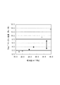
本実施の形態では、上記のガス発生量の低下を抑制するため、正極活物質粒子の立体構造に着目した。また、立体構造を規定する基準として、DBP吸油量を採用した。なおDBP吸油量は、合剤ペーストの粘度に影響を及ぼす。このことを踏まえ、正極活物質のDBP吸油量を横軸に、ずり速度2(/秒)での撹拌時のペースト粘度を縦軸にとり、評価したものが、電池の性能を領域I〜Vに分けて評価したものが図1である。 In this Embodiment, in order to suppress the fall of said gas generation amount, attention was paid to the three-dimensional structure of the positive electrode active material particles. Moreover, the DBP oil absorption was adopted as a standard for defining the three-dimensional structure. The DBP oil absorption affects the viscosity of the mixture paste. Based on this, the DBP oil absorption amount of the positive electrode active material is plotted on the horizontal axis, the paste viscosity during stirring at a shear rate of 2 (/ sec) is plotted on the vertical axis, and the battery performance is evaluated in the regions I to V. FIG. 1 shows the results evaluated separately.
図1にかかる電池では、固形分率68%で、正極活物質91質量部に対して、第1導電材3質量部、第2導電材3質量部、バインダー3質量部を含むペーストを集電箔に塗布して正極板を作製した。正極板の密度は2.6〜3.0g/cm3である。各実施の形態に係る電池を、図1の座標系中の四角で表した。 In the battery according to FIG. 1, a paste containing 3 parts by mass of the first conductive material, 3 parts by mass of the second conductive material, and 3 parts by mass of the binder is collected with respect to 91 parts by mass of the positive electrode active material at a solid content of 68%. A positive electrode plate was prepared by applying to a foil. The density of the positive electrode plate is 2.6 to 3.0 g / cm 3 . The battery according to each embodiment is represented by a square in the coordinate system of FIG.
領域IIIでは、DBP吸油量が21.5〜32.5(ml/100g)で、かつペースト粘度が2.0〜8.0(Pa・秒)である。領域IIIに含まれる電池を斜線付きの四角で表し、含まれないものを白い四角で表した。領域IIIでは、ガス発生量の低下が抑制されている一方で、電池出力の低下が抑制されている。また、生産性も良好である。 In region III, the DBP oil absorption is 21.5 to 32.5 (ml / 100 g) and the paste viscosity is 2.0 to 8.0 (Pa · sec). Batteries included in region III are represented by hatched squares, and those not included are represented by white squares. In region III, a decrease in gas generation amount is suppressed, while a decrease in battery output is suppressed. Moreover, productivity is also favorable.
DBP吸油量が32.5(ml/100g)より大きい領域Iでは、過充電時のガス発生量が低下している。一方、DBP吸油量が21.5(ml/100g)より小さい領域IIでは、電池出力が低下している。
また、ペースト粘度が2.0(Pa・秒)以下の領域IVでは、ペーストの安定性が低下している。一方、ペースト粘度が8.0(Pa・秒)以上の領域Vでは、混練性と塗工性が低下している。さらに領域Vではペーストをフィルタろ過する際のフィルタ圧増加や、ペースト搬送性の悪化が懸念される。
In region I where the DBP oil absorption is greater than 32.5 (ml / 100 g), the amount of gas generated during overcharge is reduced. On the other hand, in the region II where the DBP oil absorption is smaller than 21.5 (ml / 100 g), the battery output decreases.
Further, in region IV where the paste viscosity is 2.0 (Pa · sec) or less, the stability of the paste is lowered. On the other hand, in the region V where the paste viscosity is 8.0 (Pa · sec) or more, the kneading property and the coating property are deteriorated. Further, in the region V, there is a concern about an increase in filter pressure when the paste is filtered and deterioration of paste transportability.
また、領域Vでは所望の固形分率を得るために、過剰なNMPを投入しなければならず、生産性の低下を招く恐れがある。このため、正極活物質のDBP吸油量は32.5(ml/100g)以下であることが好ましい。
なお、所望の固形分率を得る他の方法として、導電材の量を減らすことが考えられる。しかしながら、この場合、電池出力の低下を招く恐れがある。その他の方法として、バインダーの分子量を小さくすることも考えられる。しかしながら、この場合、バインダーのマイグレーション状態が悪化する恐れがある。また、導電材やバインダーにて、固形分率を制御するにも限界がある。
Further, in the region V, in order to obtain a desired solid content rate, excess NMP must be introduced, which may cause a decrease in productivity. For this reason, it is preferable that the DBP oil absorption amount of a positive electrode active material is 32.5 (ml / 100g) or less.
As another method for obtaining a desired solid content rate, it is conceivable to reduce the amount of the conductive material. However, in this case, the battery output may be reduced. Another possible method is to reduce the molecular weight of the binder. However, in this case, the migration state of the binder may be deteriorated. In addition, there is a limit to controlling the solid content with a conductive material or a binder.
上記については、実施例の効果の検証にてさらに詳細に説明する。本実施の形態の電池は、例えば電気自動車(EV)又はプラグインハイブリット自動車(PHV)等の輸送機械に搭載して、駆動電源として使用することができる。なお、本発明は上記実施の形態に限られたものではなく、趣旨を逸脱しない範囲で適宜変更することが可能である。 The above will be described in more detail in the verification of the effect of the embodiment. The battery of the present embodiment can be mounted on a transport machine such as an electric vehicle (EV) or a plug-in hybrid vehicle (PHV) and used as a drive power source. Note that the present invention is not limited to the above-described embodiment, and can be changed as appropriate without departing from the spirit of the present invention.
[実施例1]
<正極板の作製>
実施例1にかかる正極板は下記の通り作製した。正極合剤全体を100重量%としたとき、正極活物質として91.0重量%のLiNi1/3Co1/3Mn1/3O2を用いた。また、第1導電材として3.0重量%のアセチレンブラック(AB,電気化学工業株式会社製:HS100)を、第2導電材として3.0重量%の黒鉛を、それぞれ用いた。
[Example 1]
<Preparation of positive electrode plate>
The positive electrode plate according to Example 1 was produced as follows. When the entire positive electrode mixture was 100% by weight, 91.0% by weight of LiNi 1/3 Co 1/3 Mn 1/3 O 2 was used as the positive electrode active material. In addition, 3.0% by weight of acetylene black (AB, manufactured by Denki Kagaku Kogyo Co., Ltd .: HS100) was used as the first conductive material, and 3.0% by weight of graphite was used as the second conductive material.
さらにバインダーとして3.0重量%のポリフッ化ビニリデン(PVdF)(株式会社クレハ製:#1300)を用いた。正極活物質のDBP吸油量は、27.7(ml/100g)とした。 Furthermore, 3.0% by weight of polyvinylidene fluoride (PVdF) (manufactured by Kureha Co., Ltd .: # 1300) was used as a binder. The DBP oil absorption of the positive electrode active material was 27.7 (ml / 100 g).
まずNMP(N−メチル−2−ピロリドン)にバインダー(PVdF)を加えて混合した。その後、アセチレンブラック(AB)と黒鉛系材料を更に加えて混練して正極合剤ペーストを作製した。正極合剤ペーストの固形分率(NV)は68(重量%)とした。なお、正極合剤ペーストの混練は、予めアセチレンブラック(AB)と黒鉛系材料とを混合し、その後、バインダー(PVdF)を加えたNMPを添加して混練してもよい。 First, a binder (PVdF) was added to NMP (N-methyl-2-pyrrolidone) and mixed. Thereafter, acetylene black (AB) and a graphite-based material were further added and kneaded to prepare a positive electrode mixture paste. The solid content ratio (NV) of the positive electrode mixture paste was 68 (% by weight). The positive electrode mixture paste may be kneaded by previously mixing acetylene black (AB) and a graphite-based material, and then adding NMP to which a binder (PVdF) is added.
その後、正極集電体となる、15μm厚のアルミニウム箔上に、上記のようにして作製した正極合剤ペーストを目付27.0mg/cm2で塗布した。正極合剤ペーストを塗布した後、温度150℃、風速5m/secの条件で乾燥させた。最後に圧延プレス機にて圧延し、密度2.6〜3.0g/cm3に調整し、正極板とした。 Thereafter, the positive electrode material mixture paste prepared as described above was applied on a 15 μm-thick aluminum foil serving as a positive electrode current collector at a basis weight of 27.0 mg / cm 2 . After applying the positive electrode mixture paste, it was dried under conditions of a temperature of 150 ° C. and a wind speed of 5 m / sec. Finally, it was rolled with a rolling press and adjusted to a density of 2.6 to 3.0 g / cm 3 to obtain a positive electrode plate.
<負極板の作製>
天然黒鉛粉末と、SBR(スチレンブタジエンゴム)と、CMC(カルボキシメチルセルロース)とを、これらの材料の質量比が98:1:1となるように水とともに混練し、負極合剤ペーストを作製した。その後、この負極合剤ペーストを厚さ10μmの銅箔(負極集電体)に塗布して乾燥させた。最後に圧延プレス機にて圧延し、密度1.1〜1.3g/cm3に調整し、負極板とした。
<Preparation of negative electrode plate>
Natural graphite powder, SBR (styrene butadiene rubber), and CMC (carboxymethylcellulose) were kneaded with water so that the mass ratio of these materials was 98: 1: 1 to prepare a negative electrode mixture paste. Thereafter, this negative electrode mixture paste was applied to a copper foil (negative electrode current collector) having a thickness of 10 μm and dried. Finally, it was rolled with a rolling press and adjusted to a density of 1.1 to 1.3 g / cm 3 to obtain a negative electrode plate.
<電流遮断機構>
電流遮断部となる、電流遮断機構(CID機構)は下記の通り備え付けた。まず、金属箔で形成されたダイアフラム形状の電流遮断機構を作製した。電流遮断機構の縁部を、外部負極端子と電気的に接続した。また、電流遮断機構の中央部付近は、内部負極端子と電気的に接続した。
<Current interruption mechanism>
A current interruption mechanism (CID mechanism) serving as a current interruption portion was provided as follows. First, a diaphragm-shaped current interruption mechanism made of metal foil was produced. The edge of the current interruption mechanism was electrically connected to the external negative terminal. Further, the vicinity of the center of the current interrupt mechanism was electrically connected to the internal negative terminal.
電池の過剰充電によりSOCが上昇すると、ガス発生添加剤が反応してガスを発生する。発生したガスにより電池ケースと封口体とから形成される筐体内の圧力が上昇した場合に、当該圧力によりダイアフラム形状の電流遮断機構が封口体側に押し込まれる構造とした。これにより、内部負極端子と電流遮断機構との接続は切断され、内部負極端子と外部負極端子とが絶縁されるものとした。また、正極側でも同様に作製した。 When the SOC rises due to overcharging of the battery, the gas generating additive reacts to generate gas. When the pressure in the housing formed from the battery case and the sealing body is increased by the generated gas, the diaphragm-shaped current interruption mechanism is pushed into the sealing body by the pressure. As a result, the connection between the internal negative terminal and the current interrupt mechanism is disconnected, and the internal negative terminal and the external negative terminal are insulated. Moreover, it produced similarly also on the positive electrode side.
<電池の組み立て>
上記の方法で作製した正極および負極を2枚のセパレータを介して積層した。セパレータは、PEを上下二層のPPで挟んだ、三層コートセパレータを使用した。この積層体を非水電解質及び電流遮断機構と共に角型電池容器に収容し、電池容器の開口部を気密に封口した。
非水電解質としては、ECとEMCとDMCとを3:3:4の体積比で含む混合溶媒に、支持塩としてのLiPF6を約1.1mol/リットルの濃度で含有させたものを使用した。また、ガス発生添加剤として、4重量%のシクロヘキシルベンゼン(CHB)を添加した。
<Battery assembly>
The positive electrode and the negative electrode produced by the above method were laminated via two separators. The separator used was a three-layer coated separator in which PE was sandwiched between two upper and lower PP layers. This laminated body was accommodated in a rectangular battery container together with a nonaqueous electrolyte and a current interruption mechanism, and the opening of the battery container was sealed airtight.
As the non-aqueous electrolyte, a mixed solvent containing EC, EMC, and DMC in a volume ratio of 3: 3: 4 and containing LiPF 6 as a supporting salt at a concentration of about 1.1 mol / liter was used. . In addition, 4% by weight of cyclohexylbenzene (CHB) was added as a gas generating additive.
[実施例2]
正極活物質のDBP吸油量を、27.7(ml/100g)とした以外は、実施例1と同様に電池を作製した。
[実施例3]
第1導電材を3重量%、第2導電材を3重量%、正極活物質のDBP吸油量を27.2ml/100gとした以外は、実施例1と同様に電池を作製した。
[Example 2]
A battery was fabricated in the same manner as in Example 1, except that the DBP oil absorption amount of the positive electrode active material was 27.7 (ml / 100 g).
[Example 3]
A battery was fabricated in the same manner as in Example 1, except that the first conductive material was 3 wt%, the second conductive material was 3 wt%, and the DBP oil absorption amount of the positive electrode active material was 27.2 ml / 100 g.
[実施例4]
第1導電材を4重量%、第2導電材を2重量%とした以外は、実施例3と同様に電池を作製した。NMPの分量は実施例3と同じとし、固形分率の調整は行わなかった。
[実施例5]
第1導電材を2重量%、第2導電材を4重量%とした以外は、実施例3と同様に電池を作製した。NMPの分量は実施例3と同じとし、固形分率の調整は行わなかった。
[Example 4]
A battery was fabricated in the same manner as in Example 3, except that the first conductive material was 4% by weight and the second conductive material was 2% by weight. The amount of NMP was the same as in Example 3, and the solid content rate was not adjusted.
[Example 5]
A battery was fabricated in the same manner as in Example 3, except that the first conductive material was 2% by weight and the second conductive material was 4% by weight. The amount of NMP was the same as in Example 3, and the solid content rate was not adjusted.
[比較例1]
正極活物質のDBP吸油量を、39.5(ml/100g)とした以外は、実施例1と同様に電池を作製した。
[比較例2]
正極活物質のDBP吸油量を、33.4(ml/100g)とした以外は、実施例1と同様に電池を作製した。
[Comparative Example 1]
A battery was produced in the same manner as in Example 1 except that the DBP oil absorption amount of the positive electrode active material was 39.5 (ml / 100 g).
[Comparative Example 2]
A battery was produced in the same manner as in Example 1 except that the DBP oil absorption amount of the positive electrode active material was 33.4 (ml / 100 g).
[比較例3]
正極活物質のDBP吸油量を、17.6(ml/100g)とした以外は、実施例1と同様に電池を作製した。
[比較例4]
正極活物質のDBP吸油量を、20.0(ml/100g)とした以外は、実施例1と同様に電池を作製した。
[Comparative Example 3]
A battery was fabricated in the same manner as in Example 1 except that the DBP oil absorption amount of the positive electrode active material was 17.6 (ml / 100 g).
[Comparative Example 4]
A battery was produced in the same manner as in Example 1 except that the DBP oil absorption amount of the positive electrode active material was 20.0 (ml / 100 g).
[比較例5]
第1導電材を6重量%とし、第2導電材を混入しなかったこと以外は、実施例3と同様に電池を作製した。NMPの分量は実施例3と同じとし、固形分率の調整は行わなかった。
[比較例6]
第1導電材を混入せず、第2導電材を6重量%とした以外は、実施例3と同様に電池を作製した。NMPの分量は実施例3と同じとし、固形分率の調整は行わなかった。
[Comparative Example 5]
A battery was fabricated in the same manner as in Example 3, except that the first conductive material was 6% by weight and the second conductive material was not mixed. The amount of NMP was the same as in Example 3, and the solid content rate was not adjusted.
[Comparative Example 6]
A battery was fabricated in the same manner as in Example 3, except that the first conductive material was not mixed and the second conductive material was 6 wt%. The amount of NMP was the same as in Example 3, and the solid content rate was not adjusted.
[比較例7]
第1導電材を3重量%、第2導電材を2重量%とし、正極活物質を1重量%増量した以外は、実施例3と同様に電池を作製した。NMPの分量は実施例3と同じとし、固形分率の調整は行わなかった。
[比較例8]
第1導電材を4重量%とし、第2導電材を混入せず、正極活物質を2重量%増量した以外は、実施例3と同様に電池を作製した。NMPの分量は実施例3と同じとし、固形分率の調整は行わなかった。
[Comparative Example 7]
A battery was fabricated in the same manner as in Example 3, except that the first conductive material was 3% by weight, the second conductive material was 2% by weight, and the positive electrode active material was increased by 1% by weight. The amount of NMP was the same as in Example 3, and the solid content rate was not adjusted.
[Comparative Example 8]
A battery was fabricated in the same manner as in Example 3, except that the first conductive material was 4 wt%, the second conductive material was not mixed, and the positive electrode active material was increased by 2 wt%. The amount of NMP was the same as in Example 3, and the solid content rate was not adjusted.
[DBP吸油量にかかる効果の検証]
<CID機構の作動>
環境温度25℃、電流レート1Cにて、試験を開始し、CID機構の作動したSOC(%)を計測した。目標範囲をSOC165(%)以下と定め、目標範囲内のSOCで作動するものを合格とした。
表1及び図2の黒いひし形に示すように、実施例1及び2並びに比較例3及び4は合格であった。一方、表1及び図2の白いひし形に示すように、比較例1及び2は不合格であった。
[Verification of effects on DBP oil absorption]
<Operation of CID mechanism>
The test was started at an environmental temperature of 25 ° C. and a current rate of 1 C, and the SOC (%) at which the CID mechanism was operated was measured. The target range was determined to be SOC 165 (%) or less, and those operating with SOC within the target range were regarded as acceptable.
As shown in the black diamonds in Table 1 and FIG. 2, Examples 1 and 2 and Comparative Examples 3 and 4 were acceptable. On the other hand, as shown in the white diamonds of Table 1 and FIG. 2, Comparative Examples 1 and 2 were unacceptable.
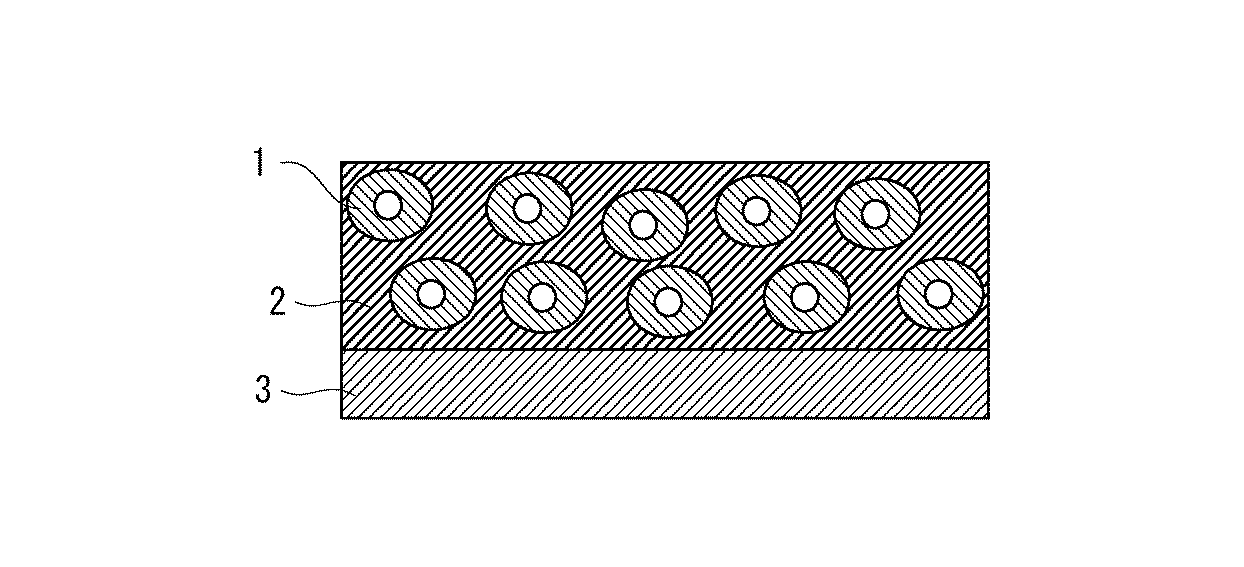
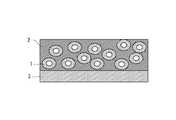
上記の結果は、以下の通り説明される。図3,4,及び6〜8では、正極活物質1及び正極活物質を取り囲む導電材及びバインダー2が配置され、集電箔3上に合剤層として形成されている。合格であった電池の正極板は図3に示されるとおり、内部空間が適切な大きさの正極活物質1を有している。かかる正極活物質の構造はDBP吸油量が適切な範囲にあることに対応する。
かかる正極を高密度にしても正極活物質1の形状がある程度維持される。このため、正極極板中に保液されているガス発生添加剤の拡散経路が大きく阻害されることはなく、反応性が確保でき、ガスの発生量が十分であった。
The above results are explained as follows. 3, 4, and 6 to 8, the positive electrode
Even if the density of the positive electrode is increased, the shape of the positive electrode
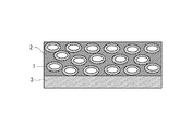
一方で、不合格であった電池の正極板は図4に示されるとおり、内部空間が大きい正極活物質1を有している。かかる正極活物質の構造はDBP吸油量が過大な範囲にあることに対応する。
かかる正極を高密度にすると、内部空間を有する正極活物質のつぶし率が大きくなるため、正極活物質1の形状が扁平となる。このため、正極極板中に保液されているガス発生添加剤の拡散経路が阻害され反応効率が悪くなり、ガスの発生量が不十分であった。
図2のグラフの回帰直線分析より、正極活物質のDBP吸油量が32.5(ml/100g)以下であれば、CID機構が動作するのに十分なガス発生量を確保できることが分かった。
On the other hand, the positive electrode plate of the battery which has been rejected has the positive electrode
When the density of such a positive electrode is increased, the crushing rate of the positive electrode active material having an internal space increases, so that the shape of the positive electrode
From the regression line analysis of the graph of FIG. 2, it was found that if the DBP oil absorption amount of the positive electrode active material is 32.5 (ml / 100 g) or less, a sufficient gas generation amount can be secured for the CID mechanism to operate.
<低充電量時の電池特性>
環境温度25℃、SOC20%での、電池の電気抵抗を測定した。抵抗値が所定の範囲となるものを合格とした。表1及び図5の黒いひし形に示すように、実施例1及び2並びに比較例1及び2は合格であった。一方で、表1及び図5の白いひし形に示すように、比較例3及び4は不合格であった。
<Battery characteristics at low charge>
The electric resistance of the battery was measured at an environmental temperature of 25 ° C. and SOC of 20%. Those having a resistance value within a predetermined range were regarded as acceptable. As shown in the black diamonds of Table 1 and FIG. 5, Examples 1 and 2 and Comparative Examples 1 and 2 were acceptable. On the other hand, as shown in the white rhombuses of Table 1 and FIG. 5, Comparative Examples 3 and 4 were unacceptable.
上記の結果は、以下の通り説明される。すなわち、比較例1及び2にかかる電池の正極板は図6に示されるとおり、正極を高密度にしても活物質の形状が変わらないため、導電パスを確保しにくく、電気抵抗が増大し、電池特性が悪化した。
一方で、実施例1及び2にかかる電池の正極板は図7に示されるとおり、正極を高密度にすると活物質の形状は若干変わるが、導電パスを確保できるため電気抵抗の増大が抑制され、電池特性の悪化が抑制された。
The above results are explained as follows. That is, as shown in FIG. 6, the positive electrode plate of the batteries according to Comparative Examples 1 and 2 does not change the shape of the active material even when the positive electrode has a high density. Therefore, it is difficult to secure a conductive path, and the electrical resistance increases. Battery characteristics deteriorated.
On the other hand, as shown in FIG. 7, the positive electrode plate of the batteries according to Examples 1 and 2 slightly changes the shape of the active material when the positive electrode has a high density, but an increase in electric resistance is suppressed because a conductive path can be secured. The deterioration of the battery characteristics was suppressed.
さらに、比較例3及び4にかかる電池の正極板は図8に示されるとおり、正極を高密度にすると活物質の形状が扁平となり、導電パスを確保できるため電気抵抗の増大が抑制され、電池特性の悪化が抑制された。
図5のグラフの回帰直線分析より、正極活物質のDBP吸油量が21.5(ml/100g)以上であれば、低充電時でも十分な出力を発揮する電池特性を確保できることが分かった。
Furthermore, as shown in FIG. 8, the positive electrode plate of the batteries according to Comparative Examples 3 and 4 has a flat active material shape when the positive electrode has a high density, and a conductive path can be secured. The deterioration of characteristics was suppressed.
From the regression line analysis of the graph of FIG. 5, it was found that when the DBP oil absorption amount of the positive electrode active material is 21.5 (ml / 100 g) or more, battery characteristics that can provide sufficient output even at low charge can be secured.
<ペースト粘度>
ずり速度2(/秒)にて撹拌した時のペースト粘度を測定した。粘度の測定には、Anton Paar社製のレオメーターMCR301を用いた。ペースト粘度の目標範囲を2.0〜8.0(Pa・秒)と定め、目標範囲内のものを合格とした。表1及び図9の黒いひし形に示すように、実施例1及び2は合格であった。一方で、表1及び図9の白いひし形に示すように、比較例1〜4は不合格であった。
正極活物質のDBP吸油量が上記所定の範囲にあり、ペースト固形分率が68%程度であれば、所望のペースト粘度を確保できることがわかった。
<Paste viscosity>
The paste viscosity when stirring at a shear rate of 2 (/ sec) was measured. For measurement of the viscosity, a rheometer MCR301 manufactured by Anton Paar was used. The target range of the paste viscosity was determined to be 2.0 to 8.0 (Pa · sec), and the one within the target range was regarded as acceptable. Examples 1 and 2 passed as shown in Table 1 and the black diamonds in FIG. On the other hand, as shown in Table 1 and the white diamonds in FIG. 9, Comparative Examples 1 to 4 were unacceptable.
It was found that when the DBP oil absorption amount of the positive electrode active material is in the predetermined range and the paste solid content rate is about 68%, a desired paste viscosity can be secured.
<ペーストの沈降性>
ペースト作製直後の、初期の固形分率、及び放置して5日後のペーストの、上澄みの固形分率を測定して変化率を求めた。固形分率の測定には、エーアンドディ社製MS70を用いた。なお沈降性の大きいものほど変化率が大きく、ペーストの安定性が悪い。
<Paste sedimentation>
The rate of change was determined by measuring the initial solid content immediately after the paste was prepared, and the solid content of the supernatant of the paste after 5 days of standing. MS70 manufactured by A & D was used for the measurement of the solid content. Note that the greater the sedimentation, the greater the rate of change and the poorer the paste stability.
変化率±5%を目標範囲とし、目標範囲内であるものを合格とした。表1及び図10の黒いひし形に示すように、実施例1及び2並びに比較例1及び2は合格であった。一方で、表1及び図10の白いひし形に示すように、比較例3及び4は不合格であった。
正極活物質のDBP吸油量が上記所定の範囲にあり、ペースト固形分率が68%程度であれば、所望のペースト安定性を確保できることがわかった。
The rate of change ± 5% was taken as the target range, and those within the target range were accepted. As shown in the black diamonds of Table 1 and FIG. 10, Examples 1 and 2 and Comparative Examples 1 and 2 were acceptable. On the other hand, as shown in Table 1 and the white diamond in FIG. 10, Comparative Examples 3 and 4 were unacceptable.
It was found that when the DBP oil absorption amount of the positive electrode active material is in the predetermined range and the paste solid content is about 68%, desired paste stability can be ensured.
[導電材量にかかる効果の検証]
<固形分率>
ペースト作製直後の、初期の固形分率を計測した。固形分率68±1(%)を目標範囲とし、目標範囲内であるものを合格とした。
[Verification of effects on the amount of conductive material]
<Solid content>
The initial solid content rate immediately after the preparation of the paste was measured. A solid content ratio of 68 ± 1 (%) was set as a target range, and a solid content rate within the target range was determined as acceptable.
表2に示すように、実施例3〜5並びに比較例7及び8は合格であったが、比較例5及び6は不合格であった。第1導電体及び第2導電体の導電材量が上記所定の範囲にあり、正極活物質のDBP吸油量が27.2(ml/100g)程度であれば、固形分率68%程度を確保できることがわかった。 As shown in Table 2, Examples 3 to 5 and Comparative Examples 7 and 8 were acceptable, but Comparative Examples 5 and 6 were unacceptable. If the amount of the conductive material of the first conductor and the second conductor is in the predetermined range and the DBP oil absorption amount of the positive electrode active material is about 27.2 (ml / 100 g), a solid content rate of about 68% is secured. I knew it was possible.
<CID機構の作動>
CID機構の作動を上記同様に計測した。目標範囲も上記同様である。表2に示すように、実施例3〜5並びに比較例5及び6は合格であったが、比較例7及び8は不合格であった。
第1導電体及び第2導電体の導電材量が上記所定の範囲にあり、正極活物質のDBP吸油量が27.2(ml/100g)程度であれば、CID機構が動作するのに十分なガス発生量を確保できることが分かった。
<Operation of CID mechanism>
The operation of the CID mechanism was measured as described above. The target range is the same as above. As shown in Table 2, Examples 3 to 5 and Comparative Examples 5 and 6 were acceptable, but Comparative Examples 7 and 8 were unacceptable.
If the amount of the conductive material of the first conductor and the second conductor is in the predetermined range and the DBP oil absorption amount of the positive electrode active material is about 27.2 (ml / 100 g), it is sufficient for the CID mechanism to operate. It was found that a sufficient amount of gas was generated.
<低充電量時の電池特性>
低充電量時の電池特性を上記同様に計測した。表2に示すように、実施例3〜5並びに比較例5,7及び8は合格であったが、比較例6は不合格であった。
第1導電体及び第2導電体の導電材量が上記所定の範囲にあり、正極活物質のDBP吸油量が27.2(ml/100g)程度であれば、低充電時でも十分な出力を発揮する電池特性を確保できることが分かった。
<Battery characteristics at low charge>
The battery characteristics at the time of low charge amount were measured in the same manner as described above. As shown in Table 2, Examples 3 to 5 and Comparative Examples 5, 7 and 8 were acceptable, but Comparative Example 6 was unacceptable.
If the amount of the conductive material of the first conductor and the second conductor is in the predetermined range and the DBP oil absorption amount of the positive electrode active material is about 27.2 (ml / 100 g), sufficient output can be obtained even at low charge. It turned out that the battery characteristic to exhibit can be ensured.
以上、本発明は、上記実施形態又は実施例の構成にのみ限定されるものではなく、本願特許請求の範囲の請求項の発明の範囲内で当業者であればなし得る各種変形、修正、組み合わせを含むことは勿論である。 As described above, the present invention is not limited to the configurations of the above-described embodiments or examples, and various modifications, corrections, and combinations that can be made by those skilled in the art within the scope of the invention of the claims of the claims of the present application. Of course.
1 正極活物質
2 導電材及びバインダー
3 集電箔(正極芯材)
DESCRIPTION OF
Claims (9)
負極板と、
前記正極板において分解反応することでガスを発生するガス発生添加剤を含む非水電解質と、
前記発生したガスに応じて電流を遮断する電流遮断部と、を備え、
前記正極活物質は、DBP吸油量が21.5〜32.5ml/100gであり、
前記導電材は、カーボンブラックと、カーボンブラック100質量部に対して、50〜200質量部のグラファイトとを有し、
前記正極板は、密度が2.6〜3.0g/cm3である、
非水電解質二次電池。 A positive electrode plate having a positive electrode active material and a conductive material;
A negative electrode plate;
A non-aqueous electrolyte containing a gas generating additive that generates a gas by decomposing in the positive electrode plate;
A current interrupting unit that interrupts current according to the generated gas,
The positive electrode active material has a DBP oil absorption of 21.5-32.5 ml / 100 g,
The conductive material has carbon black and 50 to 200 parts by mass of graphite with respect to 100 parts by mass of carbon black,
The positive electrode plate has a density of 2.6 to 3.0 g / cm 3 .
Non-aqueous electrolyte secondary battery.
前記導電材は、カーボンブラック、及びカーボンブラック100質量部に対して50〜100質量部のグラファイトからなる、請求項1又は2に記載の非水電解質二次電池。 The positive electrode plate includes 6 parts by mass of the conductive material and 3 parts by mass of a binder with respect to 91 parts by mass of the positive electrode active material,
3. The nonaqueous electrolyte secondary battery according to claim 1, wherein the conductive material is made of carbon black and 50 to 100 parts by mass of graphite with respect to 100 parts by mass of carbon black.
前記混練した材料を有する正極板を形成する形成工程と、
前記正極板の密度が2.6〜3.0g/cm3になるよう、前記正極板を圧延する圧延工程と、
正極板において分解反応することでガスを発生するガス発生添加剤を、非水電解質に添加する添加工程と、
前記正極板と、負極板と、前記非水電解質と、前記発生したガスに応じて電流を遮断する電流遮断部とを組み立てる組立工程と、を備える非水電解質二次電池の製造方法。 A kneading step of kneading carbon black and a conductive material containing 50 to 200 parts by mass of graphite and a positive electrode active material having a DBP oil absorption of 21.5 to 32.5 ml / 100 g with respect to 100 parts by mass of carbon black. When,
Forming a positive electrode plate having the kneaded material; and
A rolling step of rolling the positive electrode plate so that the density of the positive electrode plate is 2.6 to 3.0 g / cm 3 ;
An addition step of adding, to the non-aqueous electrolyte, a gas generating additive that generates gas by decomposing in the positive electrode plate;
An assembly process for assembling the positive electrode plate, the negative electrode plate, the non-aqueous electrolyte, and a current interrupting unit that interrupts current according to the generated gas.
Priority Applications (1)
| Application Number | Priority Date | Filing Date | Title |
|---|---|---|---|
| JP2012232520A JP5838952B2 (en) | 2012-10-22 | 2012-10-22 | Non-aqueous electrolyte secondary battery and manufacturing method thereof |
Applications Claiming Priority (1)
| Application Number | Priority Date | Filing Date | Title |
|---|---|---|---|
| JP2012232520A JP5838952B2 (en) | 2012-10-22 | 2012-10-22 | Non-aqueous electrolyte secondary battery and manufacturing method thereof |
Publications (2)
| Publication Number | Publication Date |
|---|---|
| JP2014086194A JP2014086194A (en) | 2014-05-12 |
| JP5838952B2 true JP5838952B2 (en) | 2016-01-06 |
Family
ID=50789080
Family Applications (1)
| Application Number | Title | Priority Date | Filing Date |
|---|---|---|---|
| JP2012232520A Active JP5838952B2 (en) | 2012-10-22 | 2012-10-22 | Non-aqueous electrolyte secondary battery and manufacturing method thereof |
Country Status (1)
| Country | Link |
|---|---|
| JP (1) | JP5838952B2 (en) |
Families Citing this family (4)
| Publication number | Priority date | Publication date | Assignee | Title |
|---|---|---|---|---|
| KR20160020237A (en) * | 2014-08-13 | 2016-02-23 | 삼성에스디아이 주식회사 | Cathode material, cathode including the same, and lithium battery including the cathode |
| KR102264906B1 (en) * | 2017-11-23 | 2021-06-14 | 주식회사 엘지에너지솔루션 | Battery module with improved safety, battery pack comprising the battery module and vehicle comprising the same |
| JP7011198B2 (en) * | 2019-06-25 | 2022-01-26 | 日亜化学工業株式会社 | Manufacturing method of electrodes for non-aqueous secondary batteries |
| CN119916228B (en) * | 2025-04-02 | 2025-07-04 | 四川工程职业技术大学 | Retired lithium battery charging safety evaluation method and system |
Family Cites Families (8)
| Publication number | Priority date | Publication date | Assignee | Title |
|---|---|---|---|---|
| JPH0992330A (en) * | 1995-07-20 | 1997-04-04 | Nikkiso Co Ltd | Non-aqueous electrolyte secondary battery |
| JP4226792B2 (en) * | 2001-02-09 | 2009-02-18 | 株式会社東芝 | Nonaqueous electrolyte secondary battery |
| JP2002343362A (en) * | 2001-05-11 | 2002-11-29 | Matsushita Electric Ind Co Ltd | Non-aqueous electrolyte secondary battery and method of manufacturing the same |
| JP4686998B2 (en) * | 2004-03-30 | 2011-05-25 | パナソニック株式会社 | Method for evaluating positive electrode active material |
| JP5364500B2 (en) * | 2009-08-20 | 2013-12-11 | 古河電池株式会社 | Method for producing positive electrode plate for non-aqueous electrolyte secondary battery |
| JP5741899B2 (en) * | 2010-11-18 | 2015-07-01 | トヨタ自動車株式会社 | Secondary battery |
| JP5598716B2 (en) * | 2010-11-26 | 2014-10-01 | トヨタ自動車株式会社 | Lithium secondary battery and manufacturing method thereof |
| JP5556629B2 (en) * | 2010-12-01 | 2014-07-23 | トヨタ自動車株式会社 | Sealed battery |
-
2012
- 2012-10-22 JP JP2012232520A patent/JP5838952B2/en active Active
Also Published As
| Publication number | Publication date |
|---|---|
| JP2014086194A (en) | 2014-05-12 |
Similar Documents
| Publication | Publication Date | Title |
|---|---|---|
| JP5924552B2 (en) | Non-aqueous electrolyte secondary battery and manufacturing method thereof | |
| KR101678798B1 (en) | Method for producing nonaqueous electrolyte secondary battery | |
| JP6048726B2 (en) | Lithium secondary battery and manufacturing method thereof | |
| EP2822083B1 (en) | Lithium secondary battery having improved rate characteristics | |
| US10818962B2 (en) | Negative electrode, lithium ion secondary battery, method of manufacturing negative electrode, and method of manufacturing lithium ion secondary battery | |
| JP5692174B2 (en) | Non-aqueous electrolyte secondary battery and method for producing non-aqueous electrolyte secondary battery | |
| JP6341151B2 (en) | Electrode sheet manufacturing method | |
| JP7443579B2 (en) | Nonaqueous electrolyte batteries and battery packs | |
| JP5999457B2 (en) | Lithium secondary battery and manufacturing method thereof | |
| US10749167B2 (en) | Lithium ion secondary battery and method of manufacturing the same | |
| CN106133952B (en) | Non-aqueous electrolyte secondary battery | |
| JP6191602B2 (en) | Lithium ion secondary battery | |
| US20190097272A1 (en) | Lithium ion secondary battery and method of manufacturing the same | |
| CN105993087A (en) | Nonaqueous electrolyte secondary battery | |
| CN106558725B (en) | Lithium-ion secondary battery | |
| JP2019036455A (en) | Non-aqueous electrolyte secondary battery | |
| JP5838952B2 (en) | Non-aqueous electrolyte secondary battery and manufacturing method thereof | |
| CN103730686A (en) | Non-aqueous electrolyte secondary battery | |
| JP6902206B2 (en) | Lithium ion secondary battery | |
| JP2015204178A (en) | Negative electrode for lithium ion secondary batteries, lithium ion secondary battery, and manufacturing methods thereof | |
| JP2014130729A (en) | Method for manufacturing nonaqueous electrolyte secondary battery | |
| WO2016157736A1 (en) | Non-aqueous electrolyte secondary cell | |
| JP2015056311A (en) | Method for manufacturing nonaqueous electrolyte secondary battery | |
| JP2019029307A (en) | Nonaqueous electrolyte secondary battery | |
| CN116404115A (en) | Positive electrode of lithium ion battery, manufacturing method thereof, and lithium ion battery |
Legal Events
| Date | Code | Title | Description |
|---|---|---|---|
| A621 | Written request for application examination |
Free format text: JAPANESE INTERMEDIATE CODE: A621 Effective date: 20150109 |
|
| A977 | Report on retrieval |
Free format text: JAPANESE INTERMEDIATE CODE: A971007 Effective date: 20150812 |
|
| A131 | Notification of reasons for refusal |
Free format text: JAPANESE INTERMEDIATE CODE: A131 Effective date: 20150818 |
|
| A521 | Request for written amendment filed |
Free format text: JAPANESE INTERMEDIATE CODE: A523 Effective date: 20150924 |
|
| TRDD | Decision of grant or rejection written | ||
| A01 | Written decision to grant a patent or to grant a registration (utility model) |
Free format text: JAPANESE INTERMEDIATE CODE: A01 Effective date: 20151013 |
|
| A61 | First payment of annual fees (during grant procedure) |
Free format text: JAPANESE INTERMEDIATE CODE: A61 Effective date: 20151026 |
|
| R151 | Written notification of patent or utility model registration |
Ref document number: 5838952 Country of ref document: JP Free format text: JAPANESE INTERMEDIATE CODE: R151 |